SOC Peripheral Components & SOC Tools
64
SOC Peripheral Components & Tools Mr. A. B. Shinde Assistant Professor, Electronics Engineering, PVPIT, Budhgaon, Sangli [email protected]
-
Upload
ambadas-shinde -
Category
Engineering
-
view
57 -
download
7
Transcript of SOC Peripheral Components & SOC Tools
SOC Peripheral
Components & Tools
Mr. A. B. Shinde
Assistant Professor,
Electronics Engineering,
PVPIT, Budhgaon, Sangli
Contents…
• XPS 16550 UART,
• XPS Serial Peripheral Interface (SPI),
• XPS Timer/Counter,
• XPS IIC Bus Interface.
• Tools: Xilinx ISE Tool &
Xilinx EDK Tool
2
References: Respective Datasheets

XPS 16550 UART
3

XPS 16550 UART
• UART: Universal Asynchronous Receiver/Transmitter
• XPS 16550 UART is an IP Core.
4

XPS 16550 UART
• Features:
• Connects as a 32-bit Slave on PLB bus of 32, 64 and 128 bits datawidth
• Hardware and software register compatible with all standard 16450and 16550 UARTs
• Implements all standard serial interface protocols
• − 5, 6, 7 or 8 bits per character
• − Odd, Even or no parity detection and generation
• − 1, 1.5 or 2 stop bit detection and generation
• − Internal baud rate generator and separate receiver clock input
• − Prioritized transmit, receive, line status
• − False start bit detection and recover
• − Line break detection and generation
• − Internal loop back diagnostic functionality
• − 16 byte transmit and receive FIFOs
5

XPS 16550 UART
• Supported Device Family:
• Virtex-4, Virtex-4Q,
• Virtex-4QV, Virtex-5,
• Virtex-5FX, Virtex-6,
• Virtex-6CX,
• Spartan-3 AN, Spartan®-3E,
• Automotive Spartan-3E, Spartan-3,
• Automotive Spartan-3, Spartan-3A,
• Automotive Spartan-3A, Spartan-3A DSP,
• Automotive Spartan-3A DSP,
• Spartan-6
6

XPS 16550 UART
• The XPS 16550 UART performs parallel to serial conversion on
characters received from the CPU and serial to parallel conversion
on characters received from a modem or microprocessor
peripheral.
• The XPS 16550 UART is capable of transmitting and receiving 8, 7,
6, or 5 bit characters. The XPS 16550 UART can transmit and receive
independently.
• The device can be configured and it’s status monitored via the
internal register set. The XPS 16550 UART is capable of signaling
receiver, transmitter and modem control interrupts.
• These interrupts can be masked and prioritized.
• The device contains a 16 bit, programmable, baud rate generator
and independent 16 byte transmit and receive FIFOs.
7

XPS 16550 UART
• The top level modules of the XPS 16550 UART are:
– PLB Interface Module
– IPIC_IF
– UART16550
8
XPS 16550 UART Top-level Block Diagram
XPS 16550 UART
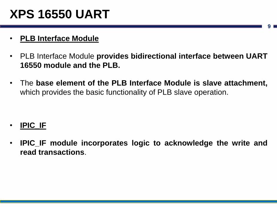
• PLB Interface Module
• PLB Interface Module provides bidirectional interface between UART
16550 module and the PLB.
• The base element of the PLB Interface Module is slave attachment,
which provides the basic functionality of PLB slave operation.
• IPIC_IF
• IPIC_IF module incorporates logic to acknowledge the write and
read transactions.
9

XPS 16550 UART
• UART 16550
• UART 16550 provides all the core features for transmission,
reception of data and modem features of UART.
• The UART 16550 module of XPS 16550 UART can be configured for
16450 or 16550 mode of operation.
• This is accomplished by the usage of generic C_IS_A_16550.
• If C_IS_A_16550 set to one, the FIFOs instantiated to support 16550
mode of operation.
• When C_IS_A_16550 is set to zero, the module works without FIFOs
in 16450 mode.
10

XPS 16550 UART11
XPS 16550 UART Detailed Block Diagram
XPS Serial Peripheral Interface (SPI)
12

XPS Serial Peripheral Interface (SPI)
• Introduction
• The XPS Serial Peripheral Interface (SPI) connects to the PLB V4.6
(Processor Local Bus with Xilinx simplifications) and provides a serial
interface to SPI devices such as SPI EEPROMs and SPI serial flash
devices.
• The SPI protocol, provides a simple method for a master and a
selected slave to exchange data.
13

XPS Serial Peripheral Interface (SPI)
• Features
• Connects as a 32-bit slave on PLB buses of 32, 64 or 128 bits
• Supports four signal interface (MOSI, MISO, SCK and SS)
• Supports slave select (SS) bit for each slave on the SPI bus
• Supports full-duplex operation
• Supports master and slave SPI modes
• Supports programmable clock phase and polarity
• Supports continuous transfer mode for automatic scanning of a
peripheral
• Supports automatic or manual slave select modes
• Supports MSB/LSB first transactions
• Supports transfer length of 8-bits, 16-bits or 32-bits
• Supports local loopback capability for testing
• Supports multiple master and multiple slave environment
14

XPS Serial Peripheral Interface (SPI)
• Supported Device Family:
• Spartan®-3, Spartan-3E,
• Spartan-3A/3AN, Spartan-3A DSP,
• Automotive Spartan-3/3A/3A DSP/ 3E,
• Spartan-6,
• Virtex®-4, Virtex-4Q,
• Virtex-4QV, Virtex-5/5FX,
• Virtex-6
15
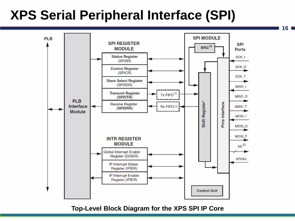
XPS Serial Peripheral Interface (SPI)16
Top-Level Block Diagram for the XPS SPI IP Core

XPS Serial Peripheral Interface (SPI)
• The XPS SPI IP Core is a full-duplex synchronous channel that
supports four-wire interface (receive, transmit, clock and slave-select)
between a master and a selected slave.
• The XPS SPI IP Core supports Manual Slave Select Mode as the
Default Mode of operation.
• This allows transfers of an arbitrary number of elements without
toggling the slave select line between elements.
• However, the user must toggle the slave select line before starting a new
transfer.
• The other mode of operation is Automatic Slave Select Mode.
• In this mode the slave select line is toggled automatically after
each element transfer.
17
XPS Serial Peripheral Interface (SPI)
• The XPS SPI IP Core supports continuous transfer mode, wherein
when configured as master the transfer continues till the data is
available in transmit register/FIFO.
• This capability is provided in both manual and automatic slave
select modes.
• When XPS SPI IP Core is configured as a slave and its slave select
line (SPISEL) goes high (i.e. in-active state) in between the data
element transfer, then the current transfer is aborted.
• Again if the slave select line goes low then the aborted data
element is transmitted again.
18

XPS Serial Peripheral Interface (SPI)
• The XPS SPI IP Core permits additional slaves to be added.
• Additional masters can be added as well.
• To eliminate conflicts, software is required to arbitrate bus control.
• The XPS SPI IP Core can communicate with both off-chip and on-
chip masters and slaves.
• The number of slaves is limited to 32 by the size of the Slave Select
Register.
• All the SPI and INTR registers are 32-bit wide. The XPS SPI IP Core
supports only word access to all SPI and INTR register modules.
19

XPS Serial Peripheral Interface (SPI)
• The XPS SPI IP Core modules are described in the sections below.
• PLB Interface Module:
• The PLB Interface Module provides the interface to the PLB V4.6
slave. The read and write transactions at the PLB are translated
into equivalent IP Interconnect (IPIC) transactions.
• The PLB Interface Module also provides an address decoding
service for XPS SPI Core.
• SPI Register Module:
• The SPI Register Module includes all memory mapped registers.
• It interfaces to the PLB.
• It consists of Status Register, Control Register, N-bit Slave Select
Register (N 32) and a pair of Transmit/Receive Registers.
20

XPS Serial Peripheral Interface (SPI)
• The XPS SPI IP Core modules are described in the sections below.
• INTR Register Module:
• The INTR Register Module consists of interrupt related registers
namely device global interrupt enable register (DGIER), IP interrupt
enable register (IPIER) and IP interrupt status register (IPISR).
• SPI Module:
• The SPI Module consists of a shift register, a parameterized baud
rate generator (BRG) and a control unit.
• It provides the SPI interface, including the control logic and
initialization logic.
• It is the heart of core.
21

XPS Serial Peripheral Interface (SPI)
• The XPS SPI IP Core modules are described in the sections below.
• Optional FIFOs:
• The Tx FIFO and Rx FIFO are implemented on both transmit and
receive paths.
• The width of Tx FIFO and Rx FIFO is same.
• The depth of these FIFO’s is 16, which is FIFO design dependent.
22

IP XPS Timer/Counter
23

IP XPS Timer/Counter
• Introduction
• The XPS Timer/Counter is a 32-bit timer module that is attached to
the PLB bus.
24
IP XPS Timer/Counter
• Features
• Connects as a 32-bit slave on PLB V4.6 buses of 32, 64 or 128 bits
• PLB interface with byte-enable support
• Two programmable interval timers with interrupt, event generation,
and event capture capabilities
• Configurable counter width
• One Pulse Width Modulation (PWM) output
• Freeze input for halting counters during software debug
25

IP XPS Timer/Counter
• Supported Device Family:
• Spartan®-6, Virtex®-6/-6CX,
• Spartan-3, Spartan-3A,
• Spartan-3E, Automotive Spartan-3/3E/3A/3A DSP,
• Spartan-3 ADSP,
• Virtex-4, QVirtex-4,
• QRVirtex-4, Virtex-5/5FX
26
IP XPS Timer/Counter27
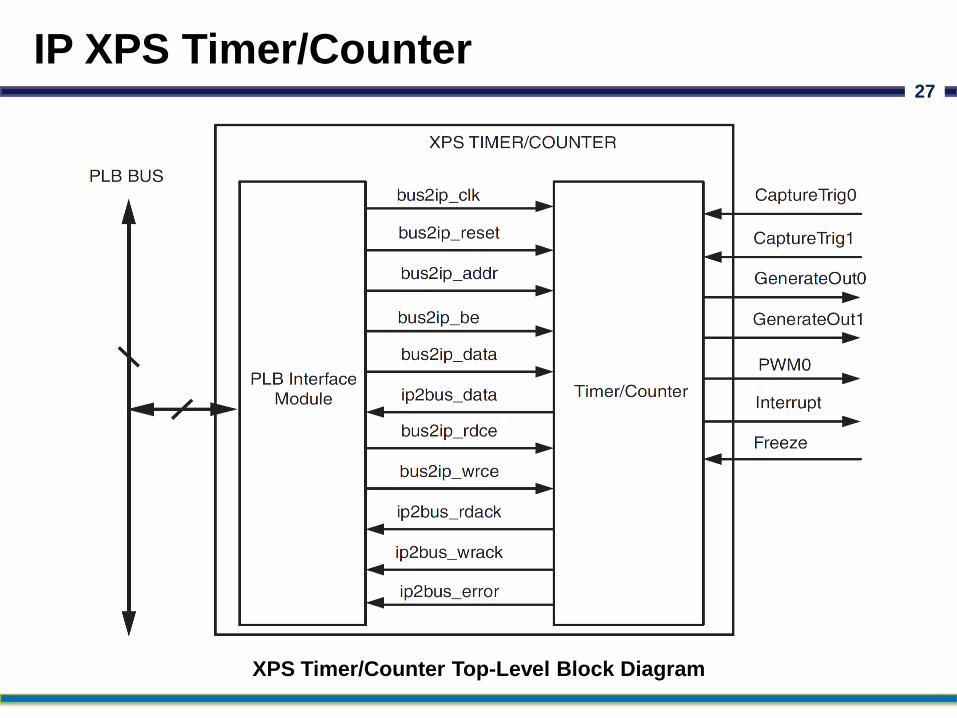
XPS Timer/Counter Top-Level Block Diagram

IP XPS Timer/Counter28
XPS Timer/Counter Detailed Block Diagram

IP XPS Timer/Counter
• The Timer/Counter is organized as two identical timer modules.
• Each timer module has an associated load register that is used to
hold either the initial value for the counter for event generation, or a
capture value, depending on the mode of the timer.
• The generate value is used to generate a single interrupt at the
expiration of an interval, or a continuous series of interrupts with a
programmable interval.
• The capture value is the timer value that has been latched on
detection of an external event.
• The clock rate of the timer modules is SPLB_Clk.
• All of the Timer/Counter interrupts are OR’ed together to generate a
single external interrupt signal.
29

IP XPS Timer/Counter
• Timer Modes:
• There are three modes that can be used with the two Timer/Counter
modules:
• Generate mode
• Capture mode
• Pulse Width Modulation (PWM) mode.
30

IP XPS Timer/Counter
• Timer Control/Status Register 0 (TCSR0)
31
ENALL: Enable All Timers
0 = No effect on timers
1 = Enable all timers (counters run)

IP XPS Timer/Counter
• Timer Control/Status Register 0 (TCSR0)
32
PWMA0: Enable Pulse Width Modulation for Timer0
0 = Disable pulse width modulation
1 = Enable pulse width modulation
T0INT: Timer0 Interrupt Read:
0 = No interrupt has occurred
1 = Interrupt has occurred
Write:
0 = No change in state of T0INT
1 = Clear T0INT (clear to ’0’)

IP XPS Timer/Counter
• Timer Control/Status Register 0 (TCSR0)
33
ENT0: Enable Timer0
0 = Disable timer (counter halts)
1 = Enable timer (counter runs)
ENIT0: Enable Interrupt for Timer0
0 = Disable interrupt signal
1 = Enable interrupt signal
IP XPS Timer/Counter
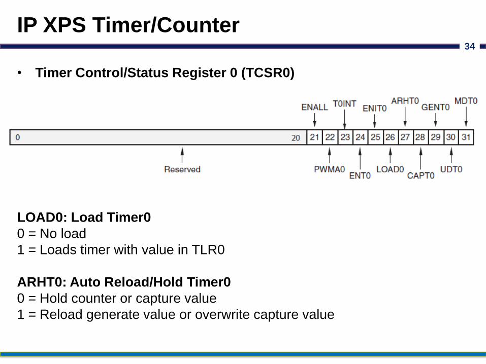
• Timer Control/Status Register 0 (TCSR0)
34
LOAD0: Load Timer0
0 = No load
1 = Loads timer with value in TLR0
ARHT0: Auto Reload/Hold Timer0
0 = Hold counter or capture value
1 = Reload generate value or overwrite capture value

IP XPS Timer/Counter
• Timer Control/Status Register 0 (TCSR0)
35
CAPT0: Enable External Capture Trigger Timer0
0 = Disables external capture trigger
1 = Enables external capture trigger
GENT0: Enable External Generate Signal Timer0
0 = Disables external generate signal
1 = Enables external generate signal

IP XPS Timer/Counter
• Timer Control/Status Register 0 (TCSR0)
36
UDT0: Up/Down Count Timer0
0 = Timer functions as up counter
1 = Timer functions as down counter
MDT0: Timer0 Mode
0 = Timer mode is generate
1 = Timer mode is capture

IP XPS Timer/Counter
• Generate Mode:
• In this mode, the value in the load register is loaded into the
counter.
• The counter, when enabled, begins to count up or down, depending
on the selection of the UDT bit in the Timer Control Status Register
(TCSR).
• On transition of the carry out of the counter, the counter stops or
automatically reloads the generate value from the load register and
continues counting as selected by the ARHT bit in the TCSR.
• The TINT bit is set in TCSR and, if enabled, the external
GenerateOut signal is driven to 1 for one clock cycle.
• This mode is useful for generating repetitive interrupts or external
signals with a specified interval.
37
IP XPS Timer/Counter
• Capture Mode:
• In Capture Mode, the value of the counter is stored in the load
register when the external capture signal is asserted.
• The TINT bit is set in the Timer Control Status Register (TCSR) on
detection of the capture event.
• The counter can be configured as an up or down counter for this
mode as determined by the selection of the UDT bit in TCSR.
• The ARHT bit controls whether the capture value is overwritten
with a new capture value before the previous TINT flag is cleared.
• This mode is useful for time tagging external events while
simultaneously generating an interrupt.
38

IP XPS Timer/Counter
• Pulse Width Modulation (PWM) Mode:
• In PWM mode, two timer/counters are used as a pair to produce an
output signal (PWM0) with a specified frequency and duty factor.
• Timer0 sets the period and Timer1 sets the high time for the PWM0
output.
39
IP XPS Timer/Counter
• Interrupts:
• The TC interrupt signals can be enabled or disabled with the ENIT
bit in the TCSR.
• The interrupt status bit (TINT) in the TCSR cannot be disabled and
always reflects the current state of the timer interrupt.
• In Generate Mode, a timer interrupt is caused by the counter rolling
over.
• In Capture Mode, the interrupt event is the capture event.
40

XPS IIC Bus Interface
41

XPS IIC Bus Interface
• Introduction
• IIC Bus (I2C or I2C) means Inter-Integrated Circuit Bus
• I2C Protocol is intended to allow multiple “slave” digital integrated
circuits (“chips”) to communicate with one or more “master” chips.
• It is intended for short distance communications within a single
device.
42

XPS IIC Bus Interface
• Introduction
• This product/module defines the architecture, hardware (signal)
interface, software (register) interface and parameterization options
for the XPS IIC module.
• It provides a low speed, two wire, serial bus interface to a large
number of popular devices.
• XPS IIC supports all features, except high speed mode, of the
Philips I2C bus, V2.1.
43

XPS IIC Bus Interface
• Features
• Connects as a 32-bit Slave on PLB bus of 32, 64 and 128 bits data width
• Master or slave operation
• Multi-master operation
• Arbitration lost interrupt with automatic mode switching from master to slave
• Calling address identification interrupt with automatic mode switching frommaster to slave
• START and STOP signal generation/detection
• Acknowledge bit generation/detection
• Bus busy detection
• Fast mode 400 KHz operation or standard mode 100 KHz
• 7 bit or 10 bit addressing
• General call enable or disable
• Transmit and receive FIFOs - 16 bytes deep
• General purpose output, 1 bit to 8 bits wide
• Filtering on the SCL and SDA signals to eliminate pulses
44
XPS IIC Bus Interface
• Supported Device Family:
• Virtex-4, Virtex-4Q,
• Virtex-4QV, Virtex-5,
• Virtex-5FX, Virtex-6,
• Virtex-6CX,
• Spartan-3E, Automotive Spartan-3E,
• Spartan-3, Automotive Spartan-3,
• Spartan-3A, Automotive Spartan-3A,
• Spartan-3A DSP, Automotive Spartan-3A DSP,
• Spartan-6
45

XPS IIC Bus Interface46
XPS IIC Top Level Block Diagram
SDA: Serial Data
SCL: Serial Clock

XPS IIC Bus Interface
• The PLB Slave Interface Module provides the transaction interface
to the PLB bus.
• A register interface block implements the address map and
connectivity for the firmware to control IIC data transfer operations.
• The module includes bi-directional I/O buffers which implement open
collector drivers for the SDA and SCL signals.
• The user must provide external pull up devices to properly hold the
bus at the logic 1 state when the connection to ground is removed.
47
XPS IIC Bus Interface
• Multi Master Operation
• The controller participates in multi master arbitration when the bus
is initially free.
• After it issues the START, other masters may participate in addressing
and the XPS IIC will correctly assigns the bus.
• However, if the bus is not free, at the START and the request to
acquire the bus is made by other masters then the XPS IIC will wait
until the bus becomes free.
48
XPS IIC Bus Interface
• Dynamic IIC Controller Logic
• The dynamic controller logic provides an interface to the XPS IIC
controller.
• The dynamic logic supports master mode only and 7 bit addressing
only.
• The dynamic logic is controlled by a start and stop bit that is located
in the transmit FIFO.
• If neither of these bits are set, then the dynamic logic is disabled.
49

XPS IIC Bus Interface
• Signal Filtering
• The Philips Specification for I2C indicates that 0 to 50 ns of pulse
rejection may be applied when operating in fast mode (>100 kHz).
• The user may specify the max amount allowed through the filtering
parameters C_SCL_INERTIAL_DELAY & C_SDA_INERTIAL_DELAY.
• These parameters specify the amount of delay in clock cycles.
• Some designs may not require any filtering and others (operating
<100 kHz) may require the maximum amount of filtering.
• It depends on many factors beyond the control of the core itself.
50
Tools Used for SoC Design
51

Xilinx ISE Tool
• ISE Design Suite: Embedded Edition
Embedded Edition provides the fundamental tools and
technologies to achieve optimal design results.
These include intelligent clock gating for dynamic power reduction
and a partial reconfiguration for greater system flexibility, size,
power, and cost reduction.
• ISE Design Suite: System Edition
It is build on top of the Embedded Edition by adding on System
Generator for DSP.
52
Xilinx ISE Tool
• ISE Design Suite: WebPACK Edition
ISE WebPACK delivers a complete, front-to-back design flow
providing instant access to the ISE features and functionality.
53

Xilinx ISE Tool
• Additional Options
The ISE Design Suite offers tools to enhance designer productivity and
flexible configurations.
• High-Level Synthesis – Vivado High-Level Synthesis accelerates IP
creation by enabling C, C++ and System C specifications.
• Partial Reconfiguration – It allows designers to change functionality
on the fly, eliminating the need to fully reconfigure.
• ChipScope – The ChipScope Pro Serial I/O Toolkit provides a fast,
easy and interactive setup and debug of serial I/O channels in high-
speed FPGA designs for use with the WebPACK edition.
54

Xilinx ISE Tool
• Additional Options
The ISE Design Suite offers tools to enhance designer productivity and
flexible configurations.
• Embedded Development Kit – It is an integrated development
environment for designing embedded processing systems for use
with WebPACK edition.
• System Generator for DSP – The industry’s leading high-level tool for
designing high-performance DSP systems using Xilinx devices for
use with the WebPACK edition.
55

Xilinx EDK Tool
• It is an embedded hardware platform typically consists of one or
more processors, peripherals and memory blocks, interconnected
via processor buses.
• It also has port connections to the outside world.
• Each of the processor cores parameters can be adjusted to customize
its behavior.
56

Xilinx EDK Tool
• This kit includes Xilinx Platform Studio (XPS) and the Software
Development kit (SDK), as well as all the documentation and IP cores.
• The Embedded Development Kit Provides:
– Xilinx Platform Studio (XPS) Tool Suite –
XPS can be used to configure the embedded system architecture,
buses and peripherals.
– Software Development Kit (SDK) –
SDK is the recommended software-centric design environment.
– Real-Time Operating System and Embedded OS Support -
Provides design support and board support package for numerous
third party suppliers in the Xilinx systems.
57

System Design Process
• The tools provided with EDK are designed to assist in all phases of the
embedded design process
58

Xilinx Platform Studio
• XPS provides an integrated environment for creating embedded
processor systems based on MicroBlaze and PowerPC processors.
• XPS also provides an editor and a project management interface to
create and edit source code.
• From XPS, you can run all embedded system tools needed to
process hardware system components.
• XPS offers the following features:
– Ability to add processor and peripheral cores, edit core
parameters, and make bus and signal connections to generate an
MHS file.
– Ability to generate and view a system block diagram and/or
design report.
– Ability to export hardware specification files for import into
SDK.
59

Xilinx Platform Studio
• XPS Tools and Utilities:
• The Base System Builder Wizard (BSB):
– BSB wizard helps you quickly to build a working system.
– Some embedded design projects can be completed using the BSB
wizard alone.
• The Create and Import Peripheral Wizard (CIP):
– CIP wizard helps you create your own peripherals and import them
into XPS-compliant projects.
– In the Create mode, the CIP wizard creates templates that help you
implement your peripheral.
– In the Import mode, this creates the interface files and directory
structures that are necessary to make your peripheral visible to the
various tools in XPS.
60
Xilinx Platform Studio
• XPS Tools and Utilities:
• Platform Generator (Platgen):
– Platgen compiles the high-level description of embedded processor
system into HDL.netlists.
• FXPS Command Line or “no window” Mode:
– XPS includes a “no window” mode that allows you to run from an
operating system command line.
61

Xilinx Platform Studio
• XPS Tools and Utilities:
• Debug Configuration Wizard
– One can instantiate a ChipScope core to monitor the Processor
Local Bus (PLB) or any other system-level signals.
– You can also provide JTAG-based virtual input and output for
monitoring the actual status.
• Simulation Model Generator (Simgen)
– The Simulation Platform Generation tool (Simgen) generates and
configures various simulation models for the hardware.
62

Software Development Kit
• The Software Development Kit (SDK) provides a development
environment for software application projects.
• SDK has the following features:
– Supports development of software applications on single
processor or multiprocessor systems.
– Imports the XPS-generated hardware platform definition.
– Has the ability to create and configure board support packages
(BSPs) for third-party OS.
– Provides off-the-shelf sample software projects to test the
hardware and software functionality.
– Has feature-rich C/C++ code editor and compilation environment
63

64
Thank You…
This presentation is published only for Educational Purpose