
SoC it to EM: electromagnetic side-channel attacks on a ...SoC it to EM: electromagnetic...
30
SoC it to EM: electromagnetic side-channel attacks on a complex system-on-chip J. Longo 1 , E. De Mulder 2 , D. Page 1 , and M. Tunstall 2 1 Department of Computer Science, University of Bristol, Merchant Venturers Building, Woodland Road, Bristol, BS8 1UB, United Kingdom. {jake.longo,daniel.page}@bristol.ac.uk 2 Rambus Cryptography Research Division, 425 Market Street, 11th Floor, San Francisco, CA 94105, United States. {elke.demulder,michael.tunstall}@cryptography.com Abstract. Increased complexity in modern embedded systems has pre- sented various important challenges with regard to side-channel attacks. In particular, it is common to deploy SoC-based target devices with high clock frequencies in security-critical scenarios; understanding how such features align with techniques more often deployed against simpler de- vices is vital from both destructive (i.e., attack) and constructive (i.e., evaluation and/or countermeasure) perspectives. In this paper, we in- vestigate electromagnetic-based leakage from three different means of executing cryptographic workloads (including the general purpose ARM core, an on-chip co-processor, and the NEON core) on the AM335x SoC. Our conclusion is that addressing challenges of the type above is feasible, and that key recovery attacks can be conducted with modest resources. Keywords: side-channel, electromagnetic, system on chip, ARM, NEON. 1 Introduction A significant proportion of academic literature on side-channel attacks already targets real-world devices: even a very limited list of examples, such as those against KeeLoq keyless entry systems [20,28], Xilinx FPGA bit-stream encryp- tion [34], or Atmel CryptoMemory [5] authentication, provides compelling evi- dence of their potency. However, and although clear counter-examples are iden- tifiable, such devices may often be characterised as electronically and/or archi- tecturally simple (the cryptographic aspects at least). From one perspective, this is a non-issue: use-cases such as contact-based and contactless payment cards, and trends such as Internet of Things (IoT) suggest devices of this type will abound for some time to come; the simplicity of a target in no way implies that developing and mounting attacks is simple nor without more general value. How- ever, from a different perspective, it may seem unsatisfactory since it contrasts sharply with trends in commodity micro-electronics. In particular, more complex devices with richer functionality are now routinely deployed in contexts where
Transcript of SoC it to EM: electromagnetic side-channel attacks on a ...SoC it to EM: electromagnetic...

SoC it to EM: electromagnetic side-channelattacks on a complex system-on-chip
J. Longo1, E. De Mulder2, D. Page1, and M. Tunstall2
1 Department of Computer Science, University of Bristol,Merchant Venturers Building, Woodland Road,
Bristol, BS8 1UB, United Kingdom.{jake.longo,daniel.page}@bristol.ac.uk2 Rambus Cryptography Research Division,
425 Market Street, 11th Floor,San Francisco, CA 94105, United States.
{elke.demulder,michael.tunstall}@cryptography.com
Abstract. Increased complexity in modern embedded systems has pre-sented various important challenges with regard to side-channel attacks.In particular, it is common to deploy SoC-based target devices with highclock frequencies in security-critical scenarios; understanding how suchfeatures align with techniques more often deployed against simpler de-vices is vital from both destructive (i.e., attack) and constructive (i.e.,evaluation and/or countermeasure) perspectives. In this paper, we in-vestigate electromagnetic-based leakage from three different means ofexecuting cryptographic workloads (including the general purpose ARMcore, an on-chip co-processor, and the NEON core) on the AM335x SoC.Our conclusion is that addressing challenges of the type above is feasible,and that key recovery attacks can be conducted with modest resources.
Keywords: side-channel, electromagnetic, system on chip, ARM, NEON.
1 Introduction
A significant proportion of academic literature on side-channel attacks alreadytargets real-world devices: even a very limited list of examples, such as thoseagainst KeeLoq keyless entry systems [20,28], Xilinx FPGA bit-stream encryp-tion [34], or Atmel CryptoMemory [5] authentication, provides compelling evi-dence of their potency. However, and although clear counter-examples are iden-tifiable, such devices may often be characterised as electronically and/or archi-tecturally simple (the cryptographic aspects at least). From one perspective, thisis a non-issue: use-cases such as contact-based and contactless payment cards,and trends such as Internet of Things (IoT) suggest devices of this type willabound for some time to come; the simplicity of a target in no way implies thatdeveloping and mounting attacks is simple nor without more general value. How-ever, from a different perspective, it may seem unsatisfactory since it contrastssharply with trends in commodity micro-electronics. In particular, more complexdevices with richer functionality are now routinely deployed in contexts where

side-channel attacks are a threat. For example, smart-phones now house multi-core, System-on-Chip (SoC) components with multi-gigahertz clock frequenciesas standard, and, modulo constraints such as energy efficiency, market forceswill drive increased use of similar components over time.
Within this context, use of ElectroMagnetic (EM) side-channel leakage isparticularly attractive. Rohatgi [38] offers a comprehensive overview of boththe physical phenomenon itself plus seminal results such as [3,21,37], neither ofwhich we expand on unless specifically relevant. Versus power analysis [29], thenon-contact, spatially flexible nature of an EM-based alternative means it a)represents a less invasive means of taking acquisitions, b) avoids issues such ason-chip voltage regulation and, most importantly, c) permits targeting of specificregions of (or components on) an SoC that otherwise offer composite leakage.
Our goal in this paper is to demonstrate that by carefully translating andrefining existing techniques, EM-based side-channel attacks are viable againstmodern, complex targets. The challenges of evaluation and countermeasure in-strumentation already motivate such work, but are arguably magnified by otherconstructive applications of side-channels (e.g., protection of intellectual prop-erty [7] and Trojan hardware detection [19]) relevant to SoCs: all benefit frombetter, open (noting this topic seems to represent an active but largely undoc-umented focus of various security services [40]) understanding of the associatedleakage characteristics. We explore a single exemplar target device, namely theTexas Instruments (TI) AM335x SoC on a BeagleBone Black development board,with respect to three options for execution of cryptographic workloads. Followingthe relevant background material in Section 2, our contribution is, concretely,the EM-based analysis of
1. AES executed by an OpenSSL server on the ARM core (Section 3),2. the proprietary AES co-processor (Section 4), and3. the NEON3 core, including bit-sliced AES (Section 5).
A central conclusion is that, while some effort is required to characterise theleakage, attack complexity does not necessarily scale in line with perceived devicecomplexity. For example, in the first case above we are able to acquire and exploitleakage at much lower frequencies than suggested by the 1 GHz system clock;this implies attack cost may also be lower than expected, and hence relying ondevice complexity (resp. obscurity) to provide security is dubious at best.
2 Background
2.1 An overview of the BeagleBone platform
BeagleBone Black is a single-board computer built around a AM335x “Sitara”SoC. Constituent components can be grouped logically into four sub-systems
3 Note that by targeting NEON, we specifically aim to add detail to the premiseintroduced during the CHES 2014 rump session talk of Bernstein and Lange: seehttp://cr.yp.to/talks/2014.09.25-2/slides-dan+tanja-20140925-2-4x3.pdf.

Integer core NEON core
L1 I-cache L1 D-cache
L2 cache
OCP bridge
176 kBROM
64 kBRAM
OCP-based L3/L4 NoC interconnect
PowerVRGPU
Cryptographicco-processor
64 kBRAM
Displaycontroller
Networkcontroller
UART
SPI
I2C
USB
...
DMA
RTC
WDT
JTAG
...
DDR-based memory interface
Fig. 1: A block diagram of the AM335x SoC, replicating [26, Figure 1-1]; note thatcomponents and sub-systems pertinent to sections in the paper are highlighted.
per [26, Figure 1-1] (which is reproduced in Figure 1 for the sake of complete-ness); the sub-systems are able to communicate via a dedicated Network-on-Chip(NoC), or interconnect. The following sections focus on the Micro-Processor Unit(MPU) and the cryptographic co-processor. Although the latter lacks public doc-umentation of the internal design (bar device driver source code4 that interfaceswith it), the former warrants further analysis: we refer to the extensive liter-ature5 for in-depth coverage. In short, however, alongside L1 and L2 cachesand on-chip memory, the central 32-bit ARM Cortex-A8 MPU core is clockedup to 1 GHz. As they dominate cryptographic use-cases, we focus on the ex-ecution of integer instructions by this core, which has two distinct pipelines:the 13-stage ARM pipeline (or core) and 10-stage NEON pipeline (or core), es-sentially a SIMD co-processor marketed as an accelerator for multimedia andsignal processing workloads. Within the ARM pipeline, the 6 execution stagesare supported by two symmetric integer pipelines, a multiplier pipeline and aload/store pipeline; operands are supplied from a 16-entry register file of 32-bitregisters. Within the NEON pipeline, the 6 execution stages are supported byinteger ALU, Multiply-ACcumulate (MAC) and load-store pipelines; operandsare supplied from a 256-byte register file, which can be viewed as comprising 32double-word (64-bit) or 16 quad-word (128-bit) entries (each with sub-words ofw ∈ {8, 16, 32, 64, 128} bits) depending on the instruction type. Both pipelinesare dual-issue (meaning 2 instructions can be issued per cycle, modulo depen-dencies), and in-order (meaning instructions complete in the same order theywere issued). Instructions enter the NEON pipeline after having been decodedby the ARM pipeline, with the two decoupled using a 16-entry queue.
4 http://github.com/torvalds/linux/blob/master/drivers/crypto/omap-aes.c5 http://www.arm.com/files/pdf/A8_Paper.pdf

The central point to take away from such analysis is the high degree ofarchitectural complexity evident, even ignoring the number of components. Forexample, the MPU alone has a total of 3 clock and 4 power domains. Suchfeatures make the SoC an extremely challenging target with respect to Signal-to-Noise Ratio (SNR), and underlines the advantages offered by EM-based leakage.
2.2 Experimental environment
Acquisition and measurement equipment. To allow reproducibility, the equip-ment used throughout this paper is listed below:
– Tektronix DPO7104 1 GHz oscilloscope,– Signatec PX14400 400 MS/s digitiser,– Langer PA303 pre-amplifier plus various (e.g., low-pass) hardware filters,– Langer RF-3 mini near-field probe set,– Langer ICS105 IC scanner (or XY-table),– Matlab 2014b (with signal processing toolbox).
The configuration was therefore very standard: the target device was mountedon the XY-table to allow micro-positioning of the probe(s), which supplied anamplified, filtered signal to either the digitiser (Section 3 and Section 5) oroscilloscope (Section 4, to cope with a higher sampling rate). This limits ourremit strictly to close-range acquisitions, rather than at a distance, e.g., per [43].
Software stack. We used a standard BeagleBone Black distribution of Debian“Wheezy” on the target device (Linux kernel version 3.13.3). The device wasbooted from on-board embedded MultiMediaCard (eMMC) storage as is; nostandard system processes were disabled. On top of this platform we use OpenSSL1.0.1j, with the cryptodev extension6 enabled when appropriate.
2.3 Leakage detection and exploitation strategy
Notation. For some set or sequence x of length n, we let x[j] denote the j-thelement of x such that 0 ≤ j < n; xi then denotes the i-th such object within alarger collection, with the subscript omitted where irrelevant. We use H(x) andD(x, y) to denote the Hamming weight and distance, respectively, of some x andy. As such,
ri = DUTfk(xi) λi
models some i-th execution of an operation f on the target device DUT, involvinga security critical datum k (e.g., key material), accepting input xi and yieldingan output ri and an EM-based trace of leakage λi (a sequence of samples).Depending on the context, the target operation ranges from single instructionsto entire algorithms (e.g., AES), and, from the attacker perspective, ri and/orxi may be known or unknown and controlled or uncontrolled.
6 http://cryptodev-linux.org/

λ is essentially a function of the target device (or leakage model), the opera-tion f and input xi, plus the probe type and location (and any other parametersof the experimental environment). With this in mind, mounting a concrete attackdemands an attacker a) determines when and where (in time and/or frequencydomains) λ contains useful, exploitable leakage, and b) selects a probe configu-ration to maximise said leakage (i.e., maximise the SNR).
Leakage detection. While several strategies, e.g., [11,12,23], have been proposedto address the former challenge above, throughout this paper we use Welch’st-test. More specifically, we use the Test Vector Leakage Assessment (TVLA)methodology of Goodwill et al. [23]. Although there are several varients (fixed-versus-random and semi-fixed-versus-random for instance), the basic idea in-volves constructing two sets of test vectors V0 and V1: the former contains asingle (semi-)fixed vector, whereas the latter contains (a large number of) vec-tors chosen uniformly at random. Note that Uno et al.[42, Section II.A] use aspecial-case of this approach, with fixed and random test vectors replaced byfull- and zero-weight alternatives (the assumed maximum and minimum cases ofleakage under a Hamming weight model). For each i-th invocation of the targetdevice, the input is selected by first randomly selecting a test vector type, i.e.,
a b$← {0, 1}, then a test vector from the appropriate set, i.e., an xi
$← Vb; theresulting trace of leakage, λi, is added to a set Λb based on the test vector type.Then, we compute the t-statistic trace as
t =Λ0 − Λ1√σ20
|Λ0| +σ21
|Λ1|
where |Λb|, Λb and σ2b respectively denote the sample size, sample mean and
sample variance of set Λb. The idea is that given a threshold τ (say τ = 4.5per [23, Section 3]), if we find |t[j]| > τ then we claim significant leakage isdetected at the j-th sample: at that point there is a statistically observable dif-ference between fixed and random test vectors, so there may be data-dependentand thus potentially exploitable information present. Each following section usesthis approach: section-specific detail is included where appropriate, with a com-prehensive overview deferred to Appendix A.
3 Software-based AES
In the literature, it is common to target embedded devices (e.g., a micro-controller)executing a program on “bare-metal”, i.e., directly on the hardware. Althoughreasonable for some scenarios, a growing number of targets will execute an Oper-ating System (OS) kernel; this is even true of many smart-cards (cf. JavaCard orMULTOS). Perhaps due to the perceived increase in complexity, related attacksare less common than the bare-metal case: selected examples include Uno etal. [42] and Genkin et al. [22] who mount non-differential EM-based attacks onRSA (plus ElGamal in the latter case only) executing under Android (on ARM)

ARM and NEONregion
SRAMregion
ARM and NEONregion
SRAMregion
Fig. 2: BeagleBone Black schematic (source: http://github.com/CircuitCo/BeagleBone-Black/blob/rev_a5c/BBB_PCB.zip) from front-side (left) andback-side (right), annotated with probe locations for leakage from the SRAM(red) and ARM and NEON cores (blue).
and Windows XP (on x86), Aboulkassimi et al. [1,2] who mount differentialEM-based attacks on AES executing under Java ME (on ARM), and Pellegriniet al. [35] who mount voltage depletion fault attacks on RSA executing underLinux (on SPARC).
In this section we consider a systems-oriented scenario of the latter type.Specifically, we imagine the target is a communications device (e.g., a smart-phone) engaged in a TLS-based session with some server. As such, the attackercan observe computation of
ci = DUTAES-128-CBCk (mi) λi .
That is, AES-128 encryption, in CBC mode, of some unknown plaintext mi
under k to yield a known ciphertext ci (since it is communicated across thenetwork). Concretely, each encryption operation is performed by OpenSSL insoftware via the default T-tables-based [14, Section 4.2] implementation.
3.1 Experimental outline
Before considering an attack strategy to exploit λ and recover k, a host of ex-perimental challenges need to be addressed: the first relates to acquisition of λ.In common with analysis of other unknown/as yet unprofiled target devices, werely on initial exploration based on full control of a replica profiling device. Westress that our use of the profiling device is simply to give insight into the asso-ciated signal characteristics: although it is well known that such an approach isnot necessarily sufficient for building templates [13], we simply use it to mitigatesystemic features (e.g., of the OS scheduler, hardware and software interruptsetc.) inherent in the scenario above.
Probe location. An initial, manual scan of the SoC surface was conducted inseveral stages to identify leakage related to the execution of three kernels: aset of memory intensive operations, a spin-lock, and a set of computationally

0 1000 2000 3000 4000 5000
Sample Index
Am
plit
ude
(a) Uninterrupted.
0 1000 2000 3000 4000 5000
Sample Index
Am
plit
ude
(b) Interrupted.
Fig. 3: Impact of interrupts on the acquisition process in Section 3: whereas theuninterrupted case (left) yields a “clean” trace, the interrupted case (right) iscorrupted (during the annotated period).
0 100 200 300 400 500
Sample Index
Am
plit
ude
(a) 300 MHz.
0 50 100 150 200 250
Sample Index
Am
plit
ude
(b) 600 MHz.
0 50 100 150 200
Sample Index
Am
plit
ude
(c) 800 MHz.
0 20 40 60 80 100 120 140 160
Sample Index
Am
plit
ude
(d) 1 GHz.
Fig. 4: Impact of clock scaling on the acquisition process in Section 3: each tracerepresents execution of AES under one of the four available clock frequencies.
0 10 20 30 40 50 60 70 80
Time (ms)
0
200
400
600
800
1000
1200
Fre
quen
cy(M
Hz)
−70
−65
−60
−55
−50
−45
−40
−35
−30
Pow
er(d
b)
Fig. 5: Spectrogram plot of frequency band 0 to 1.25 GHz at our attack location,with the profiling device cycling through three kernels: a total of three iterations(left-to-right) of the memory intensive, spin-lock and computational (i.e., AES)kernels is illustrated. Note a) the indicative frequency response of AES, and b)the relatively narrow, low frequency range required to capture this response.

0 50 100 150 200 250
Sample Index
−100
−50
0
50
100
t-st
atis
tic
(a) Fixed-versus-random test.
0 10 20 30 40 50 60 70 80
Number of Traces (×1000)
−0.3
−0.2
−0.1
0.0
0.1
0.2
0.3
Cor
rela
tion
(b) Single-bit correlation.
Fig. 6: Leakage analysis results for a free-running target using 85,000 sub-tracesmatched at 600 MHz. The leakage detection test (left) shows leakage above thesignificance threshold τ = 4.5 (marked in black on the Y-axis) throughout theAES execution. The single-bit analysis (right) tracks the correct key bit hypoth-esis of the first byte over the number of sub-traces used.
intensive operations (namely AES encryption, as performed by OpenSSL). Byperiodically cycling through the kernels and monitoring the frequency response(illustrated by Figure 5), two distinct regions of interest were identified (shown inFigure 2). We attribute one region (straddling the SoC edge and SRAM bus) tothe memory intensive kernel, and hence memory access. Given that the memorybus is specific to this development kit, that no effort appears to have been madeto secure it, and that a complete operational datasheet is available7, we did notfeel it warranted further investigation even though it will likely yield exploitableleakage. The second region is located centrally on the AM335x surface, over acluster of capacitors on the back-side of the board (specifically, around C94 andC46). Motivated by a) the magnitude of the frequency response observed duringthe AES execution, but also b) the long-term trend toward stacked fabricationprocesses (and associated decrease in SNR), we fixed the probe location overthis support circuitry.
Acquisition tuning. The leakage from the selected region was identifiable usingrelatively low frequencies alone, i.e., below 100 MHz. We expect this, to somedegree, since a) AES throughout is clearly lower than the system clock frequency(one round is requires more than one instruction), and b) the on-chip discretecomponents coupled with the capacitor behave as a low-pass filter. As such,we applied a band-pass filter to the amplified signal centred on 45 MHz witha bandwidth of 24 MHz. This is interesting in so far as it allows use of lesscapable, and hence less expensive acquisition equipment. That is, rather thanuse a high-specification oscilloscope, we were able to use a lower-specificationdigitiser.
Bulk, or multi-block acquisitions. Our next step was to replace the artificial ker-nels with a “free-running” uninstrumented OpenSSL client instance: no artificial
7 http://www.micron.com/parts/dram/ddr3-sdram/mt41k256m16ha-125

(e.g., hardware, via a GPIO pin) triggers are inserted. A coarse, soft trigger isattractive, but strictly to limit acquisitions to a target session (i.e., one k) ratherthan to provide alignment per se: each trace λi acquired therefore relates to linvocations of AES rather than 1, i.e., each ci is now a (16 · l)-byte or l-blockciphertext, as generated by the TLS record layer. Such a soft trigger is easilyrealised via traffic analysis, and is additionally beneficial since it permits ci tobe known (i.e., sniffed) rather than controlled (i.e., injected) by the attacker.
Although we argue that this choice is more realistic than the alternative, ithas both positive and negative effects. On one hand, bulk acquisition significantlyreduces the wall-clock time required [6, Section 3] and allows the effect of dataand instruction caches to be largely ignored (since all but the first few AESinvocations will occur with a warm cache). On the other, we must address variouschallenges relating to systematic noise that occurs over the longer time period(and which for “one-shot” devices such as smart-cards, are normally irrelevant).
Interrupt detection and synchronisation. The OS may preempt a user process ifit does not voluntarily yield, or if the kernel needs to service an interrupt: use ofbulk acquisition necessitates we account for these interrupts, because they willbe observed more frequently during the computation of longer ciphertexts.
Figure 3 demonstrates that an uninterrupted versus interrupted trace can beidentified visually. We automate similar identification using the trace alignmentscores (i.e., a measure of the least squares [31, page 208]). To do so, we manuallyidentify and select a single uninterrupted trace for use as a template. We thenperform coarse alignment of all traces and record their score (versus the tem-plate): if the score is above an experimentally determined threshold, the traceis assumed to have been interrupted. For interrupted traces, we then have twochoices: discard them, or “clean” them by pruning the interrupted region. Wefound the low sample rate used means interrupt pruning is highly error prone(it is not always clear at which exact point the interrupt has ended and theOpenSSL process has resumed); such errors desynchronise the trace (i.e., thesub-trace for a given AES invocation) from the associated ciphertexts. Althoughdiscarding traces imposes a penalty on the total number of traces required, weopted for this approach.
Clock scaling. Finally, the OS may attempt to scale (or throttle) the clockfrequency to optimise power consumption. We observed cases where this oc-curred, although found the device would typically stabilise at 600 MHz once theOpenSSL process becomes active. AES execution under each clock configurationis shown in Figure 4, with the difference between cases clearly highlighting theresulting misalignment.
By sampling well above the Nyquist rate, it may be possible to infer theclock rate by examining the response at specific frequencies (i.e., at 300 MHz,600 MHz, 800 MHz and 1 GHz); such an approach may also facilitate interruptpruning (per the above). However, use of a low sampling rate, while advantageousin other respects, rules this approach out. Instead, we simply created a templateof AES execution at each clock frequency: any trivial comparison between each

template and target trace reveals the clock frequency used, and yields a usablesubset of traces whose clock frequency is uniform.
3.2 Analysis and discussion
Summarising the section above, to mount a concrete attack we performed anacquisition phase as follows:
1. Bulk acquire n = 1,000 traces, each including l = 256 encryption operations(meaning 4 kB of traffic per trace, and ∼ 4 MB in total).
2. Deal with systemic noise by filtering for interrupts and clock scaling; in ourexperience, this means discarding ∼ 20%.
3. From each remaining trace, extract a fragment or sub-trace for each encryp-tion operation; match these with the associated ciphertexts.
4. Realign each sub-trace, and discard any corrupted or low-quality cases; inour experience, this means discarding a further ∼ 5%.
This process yields a set of s < n · l remaining (sub-)traces, and for such n andl took ∼ 6 min. Based on this set, we then attempted to exploit the leakage. Todo so, we mounted a single-bit correlation-based attack targeting the T-table(or S-box) look-up in the final AES round. Figure 6b illustrates, without loss ofgenerality, an example for the first byte of k: it shows growth of the correlationcoefficient as the number of (sub-)traces increases. Note the correct (highlighted)hypothesis is clearly distinguished using around 20,000 (sub-)traces, meaning wecould have bulk acquired as few as 100 traces (∼ 400 kB) and still have beensuccessful. In reality, fine-tuning n before the acquisition phase is difficult sincethe attacker cannot control l (and indeed this may change from one trace toanother). However, using an adaptive choice of n such that s is large enough,the attack still succeeds.
We benchmarked this attack against a traditional alternative where an arti-ficial hardware trigger (which simultaneously aligns traces, and avoids the issueof interrupts) and fixed clock frequency were used. We found key recovery waspossible with only 3,000 (sub-)traces, ∼ 7 times fewer than our free-running sce-nario. We posit the gap between the two can be incrementally reduced, since itessentially represents pre-processing inefficiency, deferring this to future work.
4 Hardware-based AES
In this section, we shift focus to hardware-based execution of AES using thecryptographic co-processor. As in Section 3, the attacker can still observe thecomputation of
ci = DUTAES-128-CBCk (mi) λi
as invoked via OpenSSL. However, the underlying encryption operations areperformed using a hardware-based AES implementation. We suggest this is likelyto reflect use-cases such as Full Disk Encryption (FDE) given the potential tomarshal operations via DMA. In such a use-case, the attacker can access ci sincethis will represent (a block of) ciphertext stored on, and readable from, the diskin question.

Hold register
AES core
Hold register
Key scheduleChaining register
Plaintext buffer
Ciphertext buffer
Fig. 7: Probable high-level architecture for the AES core within the AM335xcryptographic co-processor (CBC mode): note that various registers may bemerged (e.g., input and output hold registers), and the chaining register shouldbe initialised with an IV.
4.1 Experimental outline
As noted in Section 2.1, there is scant documentation for the AM335x crypto-graphic co-processor: our only insight into the internal design stems from devicedrivers that support interaction with it. Since the drivers do not expose anysystem calls for use by user processes, such interaction is realised concretelyby enabling the OpenSSL cryptodev extension: each encryption operation in-voked is processed, by OpenSSL, via the associated cryptodev kernel moduleand ultimately performed by the co-processor.
Black-box architectural analysis. Treating the co-processor as a black-box, weuse the functionality offered (i.e., ECB, CBC and CTR modes, with 128-, 192-and 256-bit key sizes) and the extensive literature on similar hardware designsto infer the (probable) internal design. Specifically, the registers exposed (e.g.,for the IV) and requirement to reinitialise the key register per invocation (sothe key schedule is likely recomputed for each encryption) suggest an iterativedesign: as illustrated by Figure 7, a single (combinatorial) core is likely usedby surrounding control logic in multiple steps to realise each mode. The defaultdriver behaviour capitalises on hardware DMA support, via the scatter-gathermechanism, to operate autonomously from the ARM core.
Signal hunting. During any exploration phase, it is important to first establish a)an identifiable form and b) a base alignment point for the target signal; doing somaximises the chances of successfully detecting leakage. The two challenges areintrinsically linked, since a well defined form will facilitate alignment. However,the former challenge is perceived as being simple, because the target operationwill typically yield a pronounced, identifiable form by virtue of how it is com-puted and by what. This was true, for instance, in Section 3: we were able toeasily detect leakage from the ARM core by monitoring the frequency responseduring execution. In contrast, this is not true for the co-processor: not only is it
unclear how AES is computed, we could not identify any periodic leakage signa-ture linked to the AES operation. This is complicated further by virtue of thefact that the co-processor operates (semi-)independently of the ARM core (thusany hardware trigger used will be asynchronous to encryption operations).
Without any visual cues nor a reliable trigger, we were unsuccessful in detect-ing leakage under fixed-versus-random tests at the probe locations identified inSection 3. Further attempts to manually scan the AM335x surface at alternativeprobe locations did not yield better results. However, we did manage to detectthe DMA strobes by locating a probe over the memory access region: these are, ofcourse, inherently related to encryption operations and hence (to some degree)yield a (somewhat) synchronous trigger for activity by the co-processor. Thedifficulty with capitalising on this fact is that any memory intensive instructionsequence can cause false positives, rendering the trigger less reliable.
To combat this issue, we instead rely on saturating the DMA engine withother work: this forces the driver into a non-DMA fall-back mode, which issuesinterrupts for any memory management. These interrupts are used as a triggerfor AES operations on the co-processor. While less ideal than the free-runningscenario in Section 3, we argue this is incrementally better than a GPIO-basedhardware trigger. Specifically, it requires an attacker controlled process be co-resident on the target device (cf. “spy process” in access-driven cache attackssuch as [36]) rather than invasive alteration of the target process.
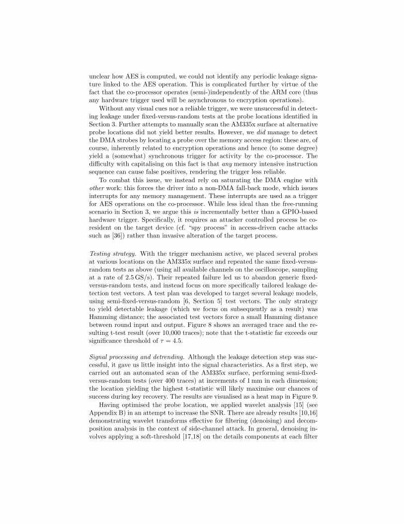
Testing strategy. With the trigger mechanism active, we placed several probesat various locations on the AM335x surface and repeated the same fixed-versus-random tests as above (using all available channels on the oscilloscope, samplingat a rate of 2.5 GS/s). Their repeated failure led us to abandon generic fixed-versus-random tests, and instead focus on more specifically tailored leakage de-tection test vectors. A test plan was developed to target several leakage models,using semi-fixed-versus-random [6, Section 5] test vectors. The only strategyto yield detectable leakage (which we focus on subsequently as a result) wasHamming distance; the associated test vectors force a small Hamming distancebetween round input and output. Figure 8 shows an averaged trace and the re-sulting t-test result (over 10,000 traces); note that the t-statistic far exceeds oursignificance threshold of τ = 4.5.
Signal processing and detrending. Although the leakage detection step was suc-cessful, it gave us little insight into the signal characteristics. As a first step, wecarried out an automated scan of the AM335x surface, performing semi-fixed-versus-random tests (over 400 traces) at increments of 1 mm in each dimension;the location yielding the highest t-statistic will likely maximise our chances ofsuccess during key recovery. The results are visualised as a heat map in Figure 9.
Having optimised the probe location, we applied wavelet analysis [15] (seeAppendix B) in an attempt to increase the SNR. There are already results [10,16]demonstrating wavelet transforms effective for filtering (denoising) and decom-position analysis in the context of side-channel attack. In general, denoising in-volves applying a soft-threshold [17,18] on the details components at each filter

0 200 400 600 800 1000 1200
Sample Index
Sam
ple
Am
plit
ude
(a) Averaged trace.
0 200 400 600 800 1000 1200
Sample Index
−150
−100
−50
0
50
100
150
200
250
300
t-st
atis
tic
(b) Averaged t-test.
0 100 200 300 400
Sample Index
Sam
ple
Am
plit
ude
(Sca
led×
5)
(c) Filtered trace.
0 100 200 300 400
Sample Index
−150
−100
−50
0
50
100
150
200
250
300
t-st
atis
tic
(d) Filtered t-test.
Fig. 8: Leakage detection test results for the AES co-processor running with asaturated DMA. The two columns relate to an averaged trace (left) and therelated t-test result (right). The rows are indicative of raw unprocessed traces(top) and traces post-processed via the wavelet analysis (bottom).
level before resynthesising the (clean) signal. However, a high-magnitude, semi-correlated interference signal overlaid the low-magnitude signal of interest. Bothsignals separately had low-noise but the interference reduced the SNR of thesignal of interest. As the interference contained overlapping frequencies with thesignal of interest, a wavelet based detrending scheme, as used in [39], providedan effective and efficient approach for separation. After trying various wavelets,ones with a lower number of vanishing moments provided better results, indi-cating the need for a fast response to sudden changes in the interference [15,41].The detrending technique follows a simple algorithm, inspired by the waveletshrinkage techniques as described in [10,16]. First, perform the DWT [30] withthe Haar wavelet. The low ratio of the sampling rate over frequency content ofthe signal required only a single level computed. Then, set all of the resultingapproximation coefficients to zero before performing an inverse DWT on thedetail coefficients. The resulting signal (shown in Figure 8) with the interferenceextracted, yields a stronger result from the leakage detection test.
4.2 Analysis and discussion
Summarising the section above, to mount a concrete attack we performed anacquisition phase as follows:

(a) AM335x surface.
0246810121416
relative x-position (mm)
0
2
4
6
8
10
12
14
16
rela
tive
y-po
siti
on(m
m)
3.0
4.5
6.0
7.5
9.0
10.5
12.0
13.5
t-st
atis
tic
(b) AM335x surface overlaid with heat-map.
Fig. 9: An illustration of results from the automatic AM335x surface scan, usinga semi-fixed-versus-random strategy to identify leakage from the cryptographicco-processor running AES-256-CBC: the t-statistic highlights the region of in-terest (modulo fidelity of the probe versus the dimensions in question) used asa subsequent probe location.
1. Saturate the DMA mechanism such that the driver operates in the non-DMAfall-back mode.
2. Acquire n = 500,000 traces, each associated with 1 encryption operationand averaged over l = 1,000 trials; match these traces with the associatedciphertexts.
3. Apply wavelet post-processing to each trace to maximise SNR.
Note that our interrupt-based trigger offers the best alignment achievable; post-processing to improve alignment was impossible, due to the lack of an identifiableform for AES operations. The acquisition process took around 3 days. To exploitthe leakage, we then applied a single-bit correlation-based attack: if si denotesthe AES state after i iterations through the AES core, we target D(si−1, si) fori = 10 relating to the final AES round. This succeeded in recovering k (albeitwith a modest amount of key enumeration to cope with one lower-ranked byte).
There are (at least) three important conclusions to draw from the above.First, the effort required to identify leakage from the device far outweighs thatof subsequent acquisition and attack phases: only by using a rigorous leakagedetection methodology were we able to get a satisfactory outcome. Second, agap exists: although Figure 8 indicates that strong leakage is identified, ourattack is unable to capitalise on this efficiently. This suggests that while leakagedetection is a necessary first step, translating it into an accurate leakage model(in our case, Hamming distance seems not to be so) is also important in concreteattack scenarios. Third, while black-box analysis gave some insight into the co-processor architecture, this did not extend to the internal implementation. Inparticular, the initial failure of our testing strategy suggests either a) the triggermechanism is not accurate enough to align traces correctly, hence decimatingthe SNR, and/or b) the co-processor is, in some way, protected against side-channel attacks. If the latter is true, it remains unclear which countermeasure isimplemented: in contrast with Heinz et al. [24], for example, there is no structure

in the signal that suggests time-based hiding, but equally attempted higher-order attacks on possible masking strategies were unsuccessful. Either way, ifa countermeasure is implemented, then we conclude it only seems effective inincreasing attack cost rather than preventing an attack.
5 NEON
NEON is a general-purpose SIMD extension to Cortex A-series ARM cores,harnessed, for example, by Bernstein and Schwabe [8] to both accelerate cryp-tographic workloads and deliver constant execution time. In terms of the ISA,each vector instruction �w processes vector operands with l = n
w elements (orsub-words), each w-bits in size; n ∈ {64, 128} is determined by the instructiontype (more specifically, whether the operands are double- or quad-words). Forthe simplest case of a pure vector operation, we can therefore say
r = x�w y 7→ 〈rw[0] = xw[0]�w yw[0], . . . , rw[l − 1] = xw[l − 1]�w yw[l − 1]〉
where tw[j] = t[j · w, . . . , (j + 1) · w − 1] is the j-th w-bit (scalar) sub-wordof vector t, and �w is the operation � for such sub-words. The ISA naturallycaptures standard logical (e.g., � = ⊕ with w = 1) and arithmetic (e.g., � =+ with w = 8, w = 16 or w = 32) operations, plus various more specialistextensions. Note that although the semantics of quad-word NEON instructionssuggest they process 128-bit operands, the pipeline will in fact issue two 64-bitmicro-operations.
5.1 Instruction-level characterisation
In this section we study leakage from (a subset of) NEON instructions by focus-ing on observation of
ri = DUT�w
(xi,yi) λi
for a range of �w but, without loss of generality, on w ∈ {8, 32} bit sub-wordswithin double-word, i.e., n = 64 bit, operands. Given that the NEON pipeline istightly coupled to the ARM pipeline, we reason the two will be physically closeon the AM335x surface; as such, we retain the same experimental configuration(e.g., same probe location) as Section 3. However, our specific remit means wecompromise by using a strictly controlled profiling device: a hardware trigger isused throughout to support instruction-level (i.e., cycle-accurate) alignment andhence a lower bound on success rate.
Leakage detection. We performed an initial exploration focused on a limited,indicative set of NEON instructions: the aim was to gather general intuitionabout their leakage characteristics. As such, we considered various potentialsources of leakage. Consider, for example, execution of a vector XOR instruc-tion (e.g., veor.u32 d0,d1,d2): one could potentially observe leakage related tooperand reads (i.e., from d1 and/or d2), computation of the operation, or resultwrite-back (i.e., to d0).

0 50 100 150 200 250
Sample Index
−0.6
−0.4
−0.2
0.0
0.2
0.4
0.6
Sam
ple
Am
plit
ude
0 50 100 150 200 250
Sample Index
0
1
2
3
4
5
t-st
atis
tic
0 5000 10000 15000 20000 25000
Number of traces
0
1
2
3
4
5
t-st
atis
tic
0 50 100 150 200 250
Sample Index
−0.6
−0.4
−0.2
0.0
0.2
0.4
0.6
Sam
ple
Am
plit
ude
0 50 100 150 200 250
Sample Index
0
1
2
3
4
5
t-st
atis
tic
0 5000 10000 15000 20000 25000
Number of traces
0
1
2
3
4
5
t-st
atis
tic
0 50 100 150 200 250
Sample Index
−0.4
−0.2
0.0
0.2
0.4
Sam
ple
Am
plit
ude
0 50 100 150 200 250
Sample Index
0
1
2
3
4
5
t-st
atis
tic
0 5000 10000 15000 20000 25000
Number of traces
0
1
2
3
4
5
t-st
atis
tic
0 50 100 150 200 250
Sample Index
−0.4
−0.3
−0.2
−0.1
0.0
0.1
0.2
0.3
Sam
ple
Am
plit
ude
0 50 100 150 200 250
Sample Index
0
1
2
3
4
5
t-st
atis
tic
0 20000 40000 60000 80000 100000
Number of traces
0
1
2
3
4
5
t-st
atis
tic
averaged trace t-test sample t-statistic over traces
veor.32
vadd.32
vmul.32
vceq.32
Fig. 10: t-statistic over number of traces for fixed-versus-random tests on NEONinstructions. In top-down order: veor.u32, vadd.u32 and vmul.u32, vceq.u32.

In summary, the results (as illustrated in Figure 10) show that a) clearoperation-dependent SPA leakage is evident, allowing, for example, construc-tion of per-instruction templates, and b) data-dependent leakage is evident, butfrom result write-back only: we could identify no leakage relating to operandreads. The latter fact, i.e., the statistically observable difference between write-back of random versus fixed results, confirms that the leakage point relates tosaid step (not reading operands from memory).
Comparing the ARM and NEON cores. Section 3 already shows that exploitableleakage from the ARM core exists; our next goal was to roughly quantify thedifference between it and the NEON core. In summary, applying the same leak-age detection strategy (as illustrated in Figure 11) shows that on the ARM corea) leakage from the operation plus both operand reads and result write-back isevident, and b) the strength of that leakage (in terms of the t-statistic growthper sample count) is greater than on the NEON core (especially for the integermultiplication instruction). Explaining this difference seems difficult without de-tailed knowledge of the implementation(s). However, it suggests a difference inthe arithmetic (e.g., multiplier) design used.
Hamming weight leakage. Having identified a set of leakage points, our nextgoal was to analyse and exploit their structure. More specifically, we attemptedto align the characterisation with standard attacks by tracking the Hammingweight of results written-back against associated leakage. This is achieved byamending the fixed-versus-random methodology, so semi-fixed test vectors areselected (for a given Hamming weight).
The results of this analysis, plus their utility, are discussed in the followingsections. We stress that, throughout, the Hamming weight of the entire n-bitresult is considered: our results show that focusing on an individual w-bit sub-word is feasible, but with the expected increase the number of traces. That is, ifone considers leakage with regards to a single w-bit sub-word then the other l−1sub-words can be considered noise (thus overcome by acquiring more traces).
Arithmetic and logical operations. Figure 12 illustrates leakage from two spe-cific NEON instructions pertinent to cryptography; further examples are shownin Figure 13. The (vector) XOR case is indicative of most instructions, in thesense that clear separation between distinct Hamming weights is evident. In con-trast, the vector polynomial multiplication is something of a special case. Theseparation between distinct Hamming weights is still evident, and potentiallyrelevant to cryptographic use-cases (e.g., [9]). However, unlike the other instruc-tions there is some “cross over” with regard to the Hamming weight and signalthat we cannot currently explain.
Comparison operations. Figure 14 illustrates leakage from a NEON vector com-parison instruction. In contrast to a scalar comparison on the ARM core (whichproduces a 1-bit result in the CPSR status register), a NEON vector comparisonsets (or clears) all w bits in each sub-word to signal true or false (i.e., forms a

0 100 200 300 400
Sample Index
−0.06
−0.04
−0.02
0.00
0.02
0.04
0.06
0.08
Sam
ple
Am
plit
ude
0 100 200 300 400
Sample Index
0
1
2
3
4
5
t-st
atis
tic
opx
opy
outroutrD
0 5000 10000150002000025000300003500040000
Number of traces
0
1
2
3
4
5
t-st
atis
tic
opx
opy
outroutrD
0 100 200 300 400
Sample Index
−0.08
−0.06
−0.04
−0.02
0.00
0.02
0.04
0.06
0.08
Sam
ple
Am
plit
ude
0 100 200 300 400
Sample Index
0
1
2
3
4
5
t-st
atis
tic
opx
opy
outroutrD
0 5000 10000 15000 20000 25000 30000
Number of traces
0
1
2
3
4
5
t-st
atis
tic
opx
opy
outroutrD
0 100 200 300 400
Sample Index
−0.06
−0.04
−0.02
0.00
0.02
0.04
0.06
Sam
ple
Am
plit
ude
0 100 200 300 400
Sample Index
0
1
2
3
4
5
t-st
atis
tic
opx
opy
outroutrD
0 50 100 150 200 250 300 350 400
Number of traces
0
1
2
3
4
5
t-st
atis
tic
opx
opy
outroutrD
averaged trace t-test sample t-statistic over traces
eor
add
mul
Fig. 11: t-statistic over number of traces for fixed-versus-random tests on ARMinstructions. In top-down order: eor, add and mul.

0 20 40 60 80 100 120
Sample Index
−0.10
−0.05
0.00
0.05
0.10
Sam
ple
Am
plit
ude
0
8
16
24
32
40
48
56
64
Ham
min
gW
eigh
t
(a) veor.u32 instruction (raw).
59.5 60.0 60.5 61.0 61.5 62.0
Sample Index
0.075
0.080
0.085
0.090
0.095
0.100
Sam
ple
Am
plit
ude
0
8
16
24
32
40
48
56
64
Ham
min
gW
eigh
t
(b) veor.u32 instruction (zoom).
0 20 40 60 80 100 120
Sample Index
−0.08
−0.06
−0.04
−0.02
0.00
0.02
0.04
0.06
0.08
Sam
ple
Am
plit
ude
0
8
16
24
32
40
48
56
64
Ham
min
gW
eigh
t
(c) vmul.p8 instruction (raw).
65.5 66.0 66.5 67.0 67.5
Sample Index
0.0680
0.0685
0.0690
0.0695
0.0700
0.0705
0.0710
Sam
ple
Am
plit
ude
0
8
16
24
32
40
48
56
64
Ham
min
gW
eigh
t
(d) vmul.p8 instruction (zoom).
Fig. 12: Illustration of Hamming weight leakage for a (limited) set of NEONarithmetic and logical instructions (where w = 32).
mask). Without loss of generality, we focus on equality comparison:
rw[j] =
{2w − 1 if xw[j] = yw[j] ,
0 otherwise.
This can be used to support branch-free, constant-time implementations: theresulting mask is used to control conditional execution of subsequent operationsin each sub-word, replacing conditional control-flow by conditional data-flow.
Our results demonstrate two important facts. First, analysis of leakage from avector comparison reveals the (total) number of sub-word results that were true(or false); this is as expected, given the maximal and minimal Hamming weightof the outputs (i.e., masks) produced in each case. Second, as demonstratedby Figure 16, it is possible to target a specific sub-word, and hence ascertainwhether it has the value 2w − 1 or 0. Doing so means considering each sub-wordindependently, treating the remaining sub-words as noise (cf. single-bit DPA).
5.2 A concrete attack on AES
The charactisation above clearly suggests Hamming weight leakage can be lever-aged in concrete attacks. As justification, we consider a scenario where the at-tacker can observe computation of
mi = DUTAES-128-CBCk (ci) λi

0 20 40 60 80 100 120
Sample Index
−0.10
−0.05
0.00
0.05
0.10
Sam
ple
Am
plit
ude
0
8
16
24
32
40
48
56
64H
amm
ing
Wei
ght
57.5 58.0 58.5 59.0 59.5
Sample Index
0.045
0.046
0.047
0.048
0.049
0.050
Sam
ple
Am
plit
ude
0
8
16
24
32
40
48
56
64
Ham
min
gW
eigh
t
0 20 40 60 80 100 120
Sample Index
−0.08
−0.06
−0.04
−0.02
0.00
0.02
0.04
0.06
0.08
Sam
ple
Am
plit
ude
0
8
16
24
32
40
48
56
64
Ham
min
gW
eigh
t
59.5 60.0 60.5 61.0 61.5
Sample Index
0.066
0.068
0.070
0.072
0.074
0.076
0.078
0.080
Sam
ple
Am
plit
ude
0
8
16
24
32
40
48
56
64
Ham
min
gW
eigh
t
0 20 40 60 80 100 120
Sample Index
−0.08
−0.06
−0.04
−0.02
0.00
0.02
0.04
0.06
0.08
Sam
ple
Am
plit
ude
0
8
16
24
32
40
48
56
64
Ham
min
gW
eigh
t
63.5 64.0 64.5 65.0 65.5 66.0
Sample Index
0.006
0.008
0.010
0.012
0.014
0.016
0.018
0.020
Sam
ple
Am
plit
ude
0
8
16
24
32
40
48
56
64
Ham
min
gW
eigh
t
raw trace zoomed trace
vadd.u32
vsub.u32
vmul.u32
Fig. 13: Illustration of Hamming weight leakage for a (limited) set of NEONarithmetic and logical instructions (where w = 32).

0 20 40 60 80 100 120
Sample Index
−0.08
−0.06
−0.04
−0.02
0.00
0.02
0.04
0.06
0.08
Sam
ple
Am
plit
ude
0 matches1 matches2 matches
(a) vceq.u32 instruction (raw).
48.0 48.5 49.0 49.5 50.0
Sample Index
−0.034
−0.032
−0.030
−0.028
−0.026
Sam
ple
Am
plit
ude
0 matches1 matches2 matches
(b) vceq.u32 instruction (zoom).
Fig. 14: Illustration of Hamming weight leakage for NEON comparison instruc-tions (where w = 32).
0 200 400 600 800 1000 1200
Sample Index
0.00
0.05
0.10
0.15
0.20
0.25
Am
plit
ude
(a) Single averaged trace.
0 5000 10000 15000 20000 25000 30000
Number of Traces
−0.20
−0.15
−0.10
−0.05
0.00
0.05
0.10
0.15
0.20
Cor
rela
tion
(b) Single byte correlation.
Fig. 15: Illustration of decryption (for a 128-byte ciphertext) using the NEON-based bit-sliced implementation of AES in OpenSSL; the corresponding correla-tion coefficient evolution suggests the attack succeeds with ∼ 5,000 traces.
but alter how AES itself is realised (compared with Section 3 and Section 4): weinstead target the NEON-based bit-sliced implementation in OpenSSL (whichstems from work by Kasper and Schwabe [27], and was enabled via the pre-processor flag -DBSAES_ASM).
This particular implementation is triggered if ci is sufficiently large (namely128 bytes, falling-back to an alternative implementation otherwise). Althoughwe note the techniques in Section 3 remain broadly applicable, for clarity weretain the same experimental environment as Section 5.1 (e.g., with a hardwaretrigger). The attack then proceeds in a fairly straightforward manner: we simplyuse key (byte, due to the representation of data used by the implementation)hypotheses based on Hamming weight of the intermediate state after the firstround InvSubBytes operation in a standard, correlation-based approach. Theattack succeeds with ∼ 5,000 traces, requiring 5000 · 128 = 625 kB of ciphertext.
5.3 A theoretical attack on NORX
Perhaps more so than other operations, the relevance of leakage from a vectorcomparison needs motivation. As such, consider NORX [4], an AEAD-based

0 20 40 60 80 100 120
Sample Index
−3
−2
−1
0
1
2
3
Dif
fere
nce
ofM
eans
×10−4
(a) Sample difference.
0 500 1000 1500 2000
Number of Averaged Trials
−6
−4
−2
0
2
4
6
Dif
fere
nce
ofM
eans
×10−4
(b) Difference over averaged trials.
Fig. 16: Illustration of a single-word attack on vceq.u32: the black hypothesisfor rw[j] = 2w − 1 (i.e., where the comparison is true, without loss of generalityfor j = 0) is clearly distinguished after averaging over 1,000 trials.
CAESAR candidate whose reference implementation8 harnesses NEON. TheNORX32-6-1 parametrisation (i.e., for 32-bit word size, 6 rounds, parallelismdegree 1, and 128-bit tag size) verifies tags as follows
/* Verify tag */A = vceqq_u32(A, LOADU(c + 0));return 0xFFFFFFFF == (vgetq_lane_u32(A, 0) & vgetq_lane_u32(A, 1) &
vgetq_lane_u32(A, 2) & vgetq_lane_u32(A, 3)) ? 0 : -1;
noting the state A (representing the computed tag) is compared with the receivedtag using vector comparison on 32-bit sub-words.
On one hand this is attractive since a) it is likely more efficient than foursequential 32-bit comparisons, and b) it is constant-time, unlike an alternativesuch as use of memcmp. On the other hand, consider a (purely hypothetical)scenario where an attacker has access to a decryption oracle, i.e., execution of
DUTNORX32-6-1k (ci) λi
for chosen ci can be observed. The resulting leakage can be used to enable tagforgery: the attacker is able to determine the total number of matching sub-wordsfor a candidate tag, so requires O(232) queries (albeit with a constant factor thathides the cost of dealing with noise etc. in acquisitions) to brute-force search fora tag matching ciphertext of their choice. Whether or not such an approach isfeasible in practice clearly depends on the context, but equally clear is the gapbetween this and the supposed (theoretical) security level.
6 Conclusions
Summary of results. In this paper we present concrete, EM-based analysis of theAM335x SoC and software executing on it. Although hard to compare directly, a
8 See http://github.com/norx/NORX. We stress our analysis should in no way beinferred as criticism of NORX within the context of CAESAR.
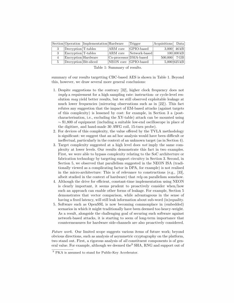
Section Operation Implementation Hardware Trigger Acquisitions Data
3 Decryption T-tables ARM core GPIO-based 3,000 46 kB
3 Encryption T-tables ARM core Network-based 100 400 kB
4 Encryption Hardware Co-processor DMA-based 500,000 7 GB
5 Decryption Bit-sliced NEON core GPIO-based 5,000 625 kB
Table 1: Summary of results.
summary of our results targetting CBC-based AES is shown in Table 1. Beyondthis, however, we draw several more general conclusions:
1. Despite suggestions to the contrary [32], higher clock frequency does notimply a requirement for a high sampling rate: instruction- or cycle-level res-olution may yield better results, but we still observed exploitable leakage atmuch lower frequencies (mirroring observations such as in [22]). This factrefutes any suggestion that the impact of EM-based attacks (against targetsof this complexity) is lessened by cost: for example, in Section 3 a (post-characterisation, i.e., excluding the XY-table) attack can be mounted using∼ $1,800 of equipment (including a suitable low-end oscilloscope in place ofthe digitiser, and hand-made 30 AWG coil, 15-turn probe).
2. For devices of this complexity, the value offered by the TVLA methodologyis significant: we suggest that an ad hoc analysis would have been difficult orineffectual, particularly in the context of an unknown target (as in Section 4).
3. Target complexity suggested at a high level does not imply the same com-plexity at lower levels. Our results demonstrate this fact in two examples.First, we were able to bypass complexity relating to the SoC architecture orfabrication technology by targeting support circuitry in Section 3. Second, inSection 5, we observed that parallelism suggested in the NEON ISA (tradi-tionally viewed as a complicating factor in DPA, for example) is not realisedin the micro-architecture: This is of relevance to constructions (e.g., [33],albeit studied in the context of hardware) that rely on parallelism somehow.
4. Although the drive for efficient, constant-time implementation using NEONis clearly important, it seems prudent to proactively consider when/howsuch an approach can enable other forms of leakage. For example, Section 5demonstrates that vector comparison, while advantageous in the sense ofhaving a fixed latency, will still leak information about sub-word (in)equality.
5. Software such as OpenSSL is now becoming commonplace in (embedded)scenarios in which it might traditionally have been deemed too heavy-weight.As a result, alongside the challenging goal of securing such software againstnetwork-based attacks, it is starting to seem of long-term importance thatcountermeasures for hardware side-channels are also proactively considered.
Future work. Our limited scope suggests various items of future work; beyondobvious directions, such as analysis of asymmetric cryptography on the platform,two stand out. First, a rigorous analysis of all constituent components is of gen-eral value. For example, although we deemed the9 SHA, RNG and support out of
9 PKA is assumed to stand for Public-Key Accelerator.

scope, understanding their leakage characteristics seems important. In the sameway, an exhaustive analysis of the NEON unit was impractical in this paper (dueto space), even though the techniques easily extend to other instructions. Doingso, and, in particular, understanding vector instructions with no natural scalarequivalent, also seem important. Second, improvements in analysis techniquescould incrementally improve specific results. For example, in Section 3 the num-ber of acquisitions required to perform a successful key recovery attack is partlydictated by how effective the pre-processing is: we expect some effort to narrowthe gap between results for the artificial and free-running cases. Likewise, Sec-tion 4 highlights the challenge of translating a method of leakage detection intoa leakage model; resolving this issue in the black-box setting seems difficult, butclearly important in scenarios such as the one investigated.
Acknowledgements
Jake Longo has been supported in part by a studentship under the EPSRCDoctoral Training Partnership (DTP) scheme. The authors would like to thankPankaj Rohatgi for general discussion, and Sami Saab for specific help with signalprocessing/analysis. We also thank both Billy Brumley and Markku Saarinen fortheir insight on NEON-based implementation, Martijn Stam for discussion aboutAEAD, and the NORX team, all of who help improved Section 5.
References
1. D. Aboulkassimi, M. Agoyan, L. Freund, J.J.A. Fournier, B. Robisson, and A. Tria.ElectroMagnetic Analysis (EMA) of software AES on Java mobile phones. InInformation Forensics and Security (WIFS), pages 1–6, 2011.
2. D. Aboulkassimi, J.J.A. Fournier, L. Freund, B. Robisson, and A. Tria. EMA as aphysical method for extracting secret data from mobile phones. IJCSA, 2(1):16–25,2013.
3. D. Agrawal, B. Archambeault, J.R. Rao, and P. Rohatgi. The EM side-channel(s).In CHES, pages 29–45. LNCS 2523, 2003.
4. J.-P. Aumasson, P. Jovanovic, and S. Neves. NORX. CAESAR submission speci-fication, version 1.1, 2014. http://norx.io/data/norx.pdf.
5. J. Balasch, B. Gierlichs, R. Verdult, L. Batina, and I. Verbauwhede. Power analysisof Atmel CryptoMemory – recovering secret keys from secure EEPROMS. In CT-RSA, pages 19–34. LNCS 7178, 2012.
6. G.T. Becker, J. Cooper, E. DeMulder, G. Goodwill, J. Jaffe, G. Kenworthy,T. Kouzminov, A. Leiserson, M. Marson, P. Rohatgi, and S. Saab. Test VectorLeakage Assessment (TVLA) methodology in practice. In ICMC, 2013.
7. G.T. Becker, M. Kasper, A. Moradi, and C. Paar. Side-channel based watermarksfor IP protection. In COSADE, pages 47–50, 2010.
8. D.J. Bernstein and P. Schwabe. NEON crypto. In CHES, pages 320–339. LNCS7428, 2012.
9. D. Camara, C.P.L. Gouvea, J. Lopez, and R. Dahab. Fast software polynomialmultiplication on ARM processors using the NEON engine. In CD-ARES, pages137–154. LNCS 8128, 2013.

10. X. Charvet and H. Pelletier. Improving the DPA attack using wavelet transform.In NIST Physical Security Testing Workshop, 2005.
11. T. Chothia and A. Guha. A statistical test for information leaks using continuousmutual information. In CSF, pages 177–190, 2011.
12. O. Choudary and M.G. Kuhn. Efficient template attacks. In CARDIS, pages253–270, 2013.
13. O. Choudary and M.G. Kuhn. Template attacks on different devices. In COSADE,pages 179–198, 2014.
14. J. Daemen and V. Rijmen. The Design of Rijndael. Springer, 2002.15. I. Daubechies. Ten Lectures on Wavelets. CBMS-NSF Regional Conference Series
in Applied Mathematics. Society for Industrial and Applied Mathematics, 1992.16. N. Debande, Y. Souissi, M.A.E. Aabid, S. Guilley, and J. Danger. Wavelet trans-
form based pre-processing for side channel analysis. In MICROW, pages 32–38,2012.
17. D.L. Donoho. De-noising by soft-thresholding. IEEE Transactions on InformationTheory, 41(3):613–627, 1995.
18. D.L. Donoho and I.M. Johnstone. Ideal spatial adaptation by wavelet shrinkage.Biometrika, 81(3):425–455, 1994.
19. D. Du, S. Narasimhan, R. Subhra Chakraborty, and S. Bhunia. Self-referencing:A scalable side-channel approach for hardware Trojan detection. In CHES, pages173–187. LNCS 6225, 2010.
20. T. Eisenbarth, T. Kasper, A. Moradi, C. Paar, M. Salmasizadeh, and M.T. ManzuriShalmani. On the power of power analysis in the real world: A complete break ofthe KeeLoq code hopping scheme. In CRYPTO, pages 203–220. LNCS 5157, 2008.
21. K. Gandolfi, C. Mourtel, and F. Olivier. Electromagnetic analysis: Concrete results.In CHES, pages 251–261. LNCS 2162, 2001.
22. D. Genkin, L. Pachmanov, I. Pipman, and E. Tromer. Stealing keys from PCsby radio: Cheap electromagnetic attacks on windowed exponentiation. CryptologyePrint Archive, Report 2015/170, 2015. http://eprint.iacr.org/.
23. G. Goodwill, B. Jun, J. Jaffe, and P. Rohatgi. A testing methodology for side-channel resistance validation. In NIST Non-Invasive Attack Testing Workshop,2011.
24. B. Heinz, J. Heyszl, and F. Stumpf. Side-channel analysis of a high-throughputAES peripheral with countermeasures. In ISIC, pages 25–29, 2014.
25. Cryptography Research Inc. Test Vector Leakage Assess-ment (TVLA) Derived Test Requirements (DTR) with AES.http://www.cryptography.com/public/pdf/TVLA-DTR-with-AES.pdf.
26. Texas Instruments. AM335x Sitara processor datasheet. Technical ReportSPRS717G, TI, 2014. http://www.ti.com/lit/ds/symlink/am3358.pdf.
27. E. Kasper and P. Schwabe. Faster and timing-attack resistant AES-GCM. InCHES, pages 1–17. LNCS 5747, 2009.
28. M. Kasper, T. Kasper, A. Moradi, and C. Paar. Breaking KeeLoq in a flash: Onextracting keys at lightning speed. In AFRICACRYPT, pages 403–420. LNCS5580, 2009.
29. P.C. Kocher, J. Jaffe, and B. Jun. Differential power analysis. In CRYPTO, pages388–397. LNCS 1666, 1999.
30. S.G. Mallat. A theory for multiresolution signal decomposition : the wavelet rep-resentation. IEEE Transactions on Pattern Analysis and Machine Intelligence,11(7):674–693, 1989.
31. S. Mangard, E. Oswald, and T. Popp. Power analysis attacks: Revealing the secretsof smart cards. Springer, 2008.

32. E. Mateos and C.H. Gebotys. Side channel analysis using Giant Magneto-Resistive(GMR) sensors. In COSADE, pages 42–49, 2011.
33. M. Medwed, F.-X. Standaert, and A. Joux. Towards super-exponential side-channelsecurity with efficient leakage-resilient PRFs. In CHES, pages 193–212. LNCS 7428,2012.
34. A. Moradi, A. Barenghi, T. Kasper, and C. Paar. On the vulnerability of FPGAbitstream encryption against power analysis attacks: extracting keys from XilinxVirtex-II FPGAs. In CCS, pages 111–124, 2011.
35. A. Pellegrini, V. Bertacco, and T. Austin. Fault-based attack of RSA authentica-tion. In DATE, pages 855–860, 2010.
36. C. Percival. Cache missing for fun and profit, 2005. http://www.daemonology.
net/papers/htt.pdf.
37. J.-J. Quisquater and D. Samyde. ElectroMagnetic Analysis (EMA): Measures andcounter-measures for smart cards. In E-SMART, pages 200–210. LNCS 2140, 2001.
38. P. Rohatgi. Electromagnetic attacks and countermeasures. In Cryptographic En-gineering, pages 407–430. Springer, 2009.
39. S. Saab, A. Leiserson, and M. Tunstall. Efficient key extraction from the pri-mary side of a switched-mode power supply. Cryptology ePrint Archive, Report2015/512, 2015. http://eprint.iacr.org/.
40. J. Scahill and J. Begley. iSpy: The CIA campaign to steal Apple’s se-crets. The Intercept, 2015. http://firstlook.org/theintercept/2015/03/10/
ispy-cia-campaign-steal-apples-secrets/.
41. G. Strang and G.J. Fix. An Analysis of the Finite Element Method. AutomaticComputation. Prentice-Hall, 1973.
42. H. Uno, S. Endo, Y. Hayashi, N. Homma, and T. Aoki. Chosen-message elec-tromagnetic analysis against cryptographic software on embedded OS. In EMC,2014.
43. A. Zajic and M. Prvulovic. Experimental demonstration of electromagnetic infor-mation leakage from modern processor-memory systems. IEEE Transactions onElectromagnetic Compatibility, 56(4):885–893, 2014.
A TVLA plan and test vector generation
Throughout the paper, we make use of the Test Vector Leakage Assessment(TVLA) methodology [25,6,23] for leakage detection and analysis. This Appendixaims to clarify how the associated test vectors were generated, hence addingdetail to discussion within the paper itself.
A.1 TVLA as per Section 3
Since OpenSSL is an open source project, we applied white-box analysis of thesource code to identify potential attack vectors. By default, OpenSSL uses aT-tables-based [14, Section 4.2] implementation of AES; this is realised by anautomatically generated assembly language program. Since no countermeasuresare implemented against hardware (versus timing) related leakage, we did notneed to apply any special-purpose leakage detection tests beyond those alreadydescribed in Section 2.3.

Test Description Result Tracecount
Round 7, round Hamming distance, 11 bytes @ 0x00 Leak 3,000
Round 7, round Hamming distance, 6 bytes @ 0x00 Leak 25,000
Round 7, round Hamming distance, 3 bytes @ 0x00 No Leak 10,000
Round 7, round Hamming distance, byte 1 @ 0x00 No Leak 10,000
Round 7, fixed round output, byte 1 @ 0x00 No Leak 10,000
Round 7, S-box out, byte 1 @ 0x00 No Leak 10,000
Round 7, round Hamming distance, byte 1 @ 0xFF No Leak 10,000
Round 7, round Hamming distance (before AddRoundKey, byte 1 @ 0x00 No Leak 10,000
Round 7, round Hamming distance, byte 12 @ 0x00 No Leak 10,000
Round 7, round Hamming distance, byte 4 @ 0x00 No Leak 10,000
Round 7, fixed output, byte 12 (before AddRoundKey) @ 0x00 No Leak 10,000
Round 14, S-box out, byte 1 @ 0x00 No Leak 10,000
Round 7, fixed state byte @ 0x00 No Leak 10,000
Round 7, fixed state short @ 0x00 No Leak 10,000
Round 7, fixed state word @ 0x00 No Leak 10,000
Round 7, fixed state 64-bit @ 0x00 No Leak 10,000
Three round Hamming distance @ 7-9, multiple bytes @ 0x00 Leak 200
Three round Hamming distance @ 6-8, multiple bytes @ 0x00 Leak 200
Round 7, S-box in/out Hamming distance minimised No Leak 1,000
Round 7, S-box in/out Hamming distance maximised No Leak 1,000
Round 7, S-box output 16 bytes @ 0x00 No Leak 1,000
Table 2: TVLA test plan, and results, as discussed in Section 4. Note that tracesare averaged over 1,000 trials (i.e., 1,000 traces equates to 1 million trials).
A.2 TVLA as per Section 4
In sharp contrast with OpenSSL, the AM335x cryptographic co-processor isa proprietary design: with no explicit documentation, we were forced to apply(informed) black-box analysis and hence develop a test plan to identify potentialleakage points. Table 2 lists (a subset of) the test vectors used, which weredeveloped according to the recommendations by Becker et al.[6] and the AES-specific TVLA requirements [25]; leakage is deemed to be evident if the t-statisticassociated with a given test vector exceeds τ = 4.5.
A set of test vectors are designed to trigger specific behaviour in AES thatmay lead to leakage detection. For example, the test “Round 7, round Hammingdistance, 11 bytes @ 0x00” will fix (the same) 11 bytes in D(s(6), s(7)) to zerowhilst the remaining 5 bytes vary. Note, that for some vectors this may result insome intermediate round functions also being fixed. Each of the vectors are runon the hardware co-processor operating in AES-256-CBC mode.
A.3 TVLA as per Section 5
Ensuring isolation of NEON core versus ARM core and memory access. Weidentified leakage related to memory access early in our analysis, and assumedthereafter that any and all such operations could be compromised: this includes

x32[0] x32[1]
y32[0] y32[1]
�32 �32
r32[0] r32[1]
Fig. 17: An illustration of the NEON instruction r = x�32 y.
memory access by the NEON core. Likewise, our analysis showed that instruc-tions executed by the ARM core exhibited strong leakage. A subtle implied issueis that we need to ensure that the leakage observed was solely from the in-structions being studied (as executed by the NEON core, versus leakage relatedmemory access for example). To do so, we placed an adequate NOP sled on ei-ther side of the instruction being studied. We concede that this limits the scopeof our analysis to exclude cross-instruction behaviour, but feel that this is anacceptable trade-off based on our original remit.
NEON fixed-versus-random test vector generation. We target four modes of leak-age for the NEON processor, namely, the input operands (opx, opy), the output(outr) and the output write-back stage (outrD ). Furthermore, care needs to betaken to primarily capture the leakage for a single lane of each instruction. Weran extensive analysis for all data widths (8, 16, 32, 64) where possible, however,we primarily discuss results related to the 32-bit data-width case (see Figure 17and Table 3). The leakage detection results showed no discernible leakage foreither input operands and relatively little difference between outr and outrD .This suggests the leakage is primarily a function of the output bits in r. This isperhaps unsurprising as we often find that the leakage is closely related to theHamming weight of a particular state.
Hamming weight analysis of NEON instructions. We focused on the Hammingweight analysis of the NEON instructions on the output of the selected instruc-tions for 32-bit widths. We generated a set of 10,000 vectors for each Hammingweight and (in a random order) executed the vectors, whilst recording the side-channel leakage. We applied post-processing on the traces to remove any erro-neous data and sorted the traces according to their respective Hamming weights.The traces for each Hamming weight were averaged and plotted as shown in Fig-ure 12, 13 and 14.
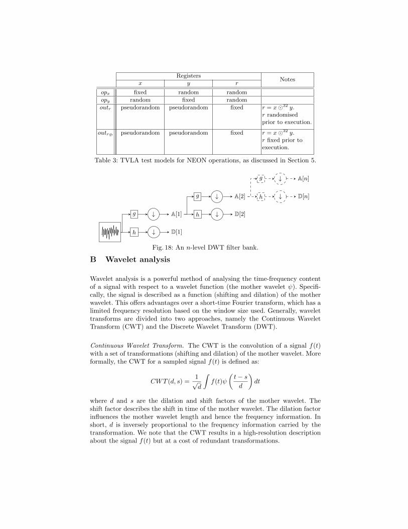
RegistersNotes
x y r
opx fixed random random
opy random fixed random
outr pseudorandom pseudorandom fixed r = x�32 y.r randomisedprior to execution.
outrD pseudorandom pseudorandom fixed r = x�32 y.r fixed prior toexecution.
Table 3: TVLA test models for NEON operations, as discussed in Section 5.
h
g
↓
↓ A[1]
D[1]
h
g
↓
↓ A[2]
D[2]
h
g
↓
↓ A[n]
D[n]
Fig. 18: An n-level DWT filter bank.
B Wavelet analysis
Wavelet analysis is a powerful method of analysing the time-frequency contentof a signal with respect to a wavelet function (the mother wavelet ψ). Specifi-cally, the signal is described as a function (shifting and dilation) of the motherwavelet. This offers advantages over a short-time Fourier transform, which has alimited frequency resolution based on the window size used. Generally, wavelettransforms are divided into two approaches, namely the Continuous WaveletTransform (CWT) and the Discrete Wavelet Transform (DWT).
Continuous Wavelet Transform. The CWT is the convolution of a signal f(t)with a set of transformations (shifting and dilation) of the mother wavelet. Moreformally, the CWT for a sampled signal f(t) is defined as:
CWT (d, s) =1√d
∫f(t)ψ
(t− sd
)dt
where d and s are the dilation and shift factors of the mother wavelet. Theshift factor describes the shift in time of the mother wavelet. The dilation factorinfluences the mother wavelet length and hence the frequency information. Inshort, d is inversely proportional to the frequency information carried by thetransformation. We note that the CWT results in a high-resolution descriptionabout the signal f(t) but at a cost of redundant transformations.

Discrete Wavelet Transform. The DWT is similar to the Fourier transform inhow it decomposes a signal into a set of terms of a basis set of functions. However,the key difference is that the Fourier transform basis functions consist of sinesand cosines, whereas the DWT basis functions are a set of mutually orthogonalwavelets generated from the mother wavelet. In addition, the DWT will use twoparameters in the expansion, i.e. the dilation and shift factors. In effect, theDWT acts as a filter bank and the depth of the bank describes the level of thetransform.
At each level of the filter bank, the frequency content of a discrete time signalis split by way of a low and high pass filter g and h respectively. The outputfrom each of the filters now contains half the frequency information previouslypresent. Following Nyquist, we can down-sample the data and remove half thepoints in the signal. The resulting signals are termed the details (denoted D)and approximations (denoted A) for the high and low frequency componentsrespectively. Each subsequent i level of DWT applies the same process to A[i−1],i.e., the approximations at the previous level, as illustrated in Figure 18. Wefavour DWT throughout this paper when referring to wavelet analysis.


![IDEA: Intrusion Detection through Electromagnetic-Signal ......variety Ransomware attacks (e.g. WannaCry [15], [16]). A comprehensive review of attacks on CPSs can be found in [17].](https://static.fdocuments.net/doc/165x107/5ecdca2d69106a0e3c7e9794/idea-intrusion-detection-through-electromagnetic-signal-variety-ransomware.jpg)


![Side-Channel Attacks · 2020. 9. 7. · • Passive attacks: side-channel attacks Observations: electromagnetic, electrical / power, acoustic, execution time, etc. [you are here]](https://static.fdocuments.net/doc/165x107/5ffe06a4e80758270d28acf5/side-channel-attacks-2020-9-7-a-passive-attacks-side-channel-attacks-observations.jpg)


