
SNIPER FIRE LOCALIZATION USING WIRELESS SENSOR … · SNIPER FIRE LOCALIZATION USING WIRELESS...
8
SNIPER FIRE LOCALIZATION USING WIRELESS SENSOR NETWORKS AND GENETIC ALGORITHM BASED DATA FUSION Patrick Kuckertz, Junaid Ansari, Janne Riihij¨ arvi and Petri M¨ ah¨ onen Department of Wireless Networks, RWTH Aachen University, Aachen, Germany ABSTRACT This paper presents the design, implementation and perfor- mance evaluation of a wireless sensor network based sniper fire localization system. Time-of-arrival (TOA) measure- ments from various sensor nodes are fused together for es- timating various parameters of a supersonic projectile, in- cluding its trajectory and speed. Our system uses a genetic algorithm based data fusion framework. The system uses a novel approach for the selection of TOA measurements. We obtained very low error bounds both in the trajectory and velocity estimation results. We believe that the presented comprehensive design details of different components of the system, the developed simulation tool and the validation of results from real shooting experiments will be useful to the community. INTRODUCTION Snipers pose a potential threat to diplomats in many parts of the world. In many of the scenarios, a particular area or building needs to be guarded and protected against snipers. We provide a wireless sensor network (WSN) based solution for locating snipers targeting a particular building situated inside the protection area. For estimating the trajectory of a fast moving bullet (a supersonic projectile) coming towards a building, we propose to deploy many inexpensive wireless sensor nodes around the building. These nodes are equipped with a broadband microphone based customized analog cir- cuit board, which is capable of detecting the shockwave gen- erated by the supersonic projectile. All the nodes must be time synchronized with each other so that all the individual events are analyzed at the common reference time. Fig. 1 shows the configuration of the WSN based system. The in- dividual sensor nodes perform time-of-arrival (TOA) mea- surements and send their individual detection information to a gateway node, attached to a PC. The PC performs fusion of the TOA measurements to determine the trajectory esti- mation parameters using a genetic algorithm (GA). When a bullet is fired, it generates a shockwave and a muz- zle blast. Our system does not aim to rely on the muzzle blast because its range is limited to the proximity of the sniper’s physical location and it requires that the sniper is very near to the sensor nodes, which might not be the case. Furthermore, most of the present day weapons are equipped with a silencer to suppress the muzzle blast. It may be noted that when a bullet approaches a building (surrounded by sen- sor nodes), only the nodes lying between the sniper and the building receive the TOA measurements. The nodes lying behind the building (shadowed nodes) do not receive TOA of the shockwave and hence will not be considered for lo- calization. Figure 1: Wireless sensor network based trajectory estima- tion system for a supersonic projectile. A customized circuit board attached to each sensor node detects the shockwave generated by the flying supersonic projectile. The sensor nodes transmit the detection information to a gateway node, which is attached to a PC, where data fusion algorithm for computing the trajectory of the projectile is implemented. The rest of the paper includes the related work, the mathe- matical formulation for TOA calculation at a sensor node, the overall embedded system architecture. Later on, we comprehensively describe various components of the ge- netic algorithm based TOA fusion framework and discuss 1 of 8
Transcript of SNIPER FIRE LOCALIZATION USING WIRELESS SENSOR … · SNIPER FIRE LOCALIZATION USING WIRELESS...

SNIPER FIRE LOCALIZATION USING WIRELESS SENSOR NETWORKS ANDGENETIC ALGORITHM BASED DATA FUSION
Patrick Kuckertz, Junaid Ansari, Janne Riihijarvi and Petri MahonenDepartment of Wireless Networks, RWTH Aachen University, Aachen, Germany
ABSTRACT
This paper presents the design, implementation and perfor-mance evaluation of a wireless sensor network based sniperfire localization system. Time-of-arrival (TOA) measure-ments from various sensor nodes are fused together for es-timating various parameters of a supersonic projectile, in-cluding its trajectory and speed. Our system uses a geneticalgorithm based data fusion framework. The system uses anovel approach for the selection of TOA measurements. Weobtained very low error bounds both in the trajectory andvelocity estimation results. We believe that the presentedcomprehensive design details of different components of thesystem, the developed simulation tool and the validation ofresults from real shooting experiments will be useful to thecommunity.
INTRODUCTION
Snipers pose a potential threat to diplomats in many partsof the world. In many of the scenarios, a particular area orbuilding needs to be guarded and protected against snipers.We provide a wireless sensor network (WSN) based solutionfor locating snipers targeting a particular building situatedinside the protection area. For estimating the trajectory of afast moving bullet (a supersonic projectile) coming towardsa building, we propose to deploy many inexpensive wirelesssensor nodes around the building. These nodes are equippedwith a broadband microphone based customized analog cir-cuit board, which is capable of detecting the shockwave gen-erated by the supersonic projectile. All the nodes must betime synchronized with each other so that all the individualevents are analyzed at the common reference time. Fig. 1shows the configuration of the WSN based system. The in-dividual sensor nodes perform time-of-arrival (TOA) mea-surements and send their individual detection information toa gateway node, attached to a PC. The PC performs fusionof the TOA measurements to determine the trajectory esti-
mation parameters using a genetic algorithm (GA).
When a bullet is fired, it generates a shockwave and a muz-zle blast. Our system does not aim to rely on the muzzleblast because its range is limited to the proximity of thesniper’s physical location and it requires that the sniper isvery near to the sensor nodes, which might not be the case.Furthermore, most of the present day weapons are equippedwith a silencer to suppress the muzzle blast. It may be notedthat when a bullet approaches a building (surrounded by sen-sor nodes), only the nodes lying between the sniper and thebuilding receive the TOA measurements. The nodes lyingbehind the building (shadowed nodes) do not receive TOAof the shockwave and hence will not be considered for lo-calization.
Figure 1: Wireless sensor network based trajectory estima-tion system for a supersonic projectile. A customized circuitboard attached to each sensor node detects the shockwavegenerated by the flying supersonic projectile. The sensornodes transmit the detection information to a gateway node,which is attached to a PC, where data fusion algorithm forcomputing the trajectory of the projectile is implemented.
The rest of the paper includes the related work, the mathe-matical formulation for TOA calculation at a sensor node,the overall embedded system architecture. Later on, wecomprehensively describe various components of the ge-netic algorithm based TOA fusion framework and discuss
1 of 8
jan
Text Box
© IEEE. Personal use of this material is permitted. However, permission to reprint/republish this material for advertising or promotional purposes or for creating new collective works for resale or redistribution to servers or lists, or to reuse any copyrighted component of this work in other works must be obtained from the IEEE.

the results. Finally, we conclude the article and proposesome future enhancements to the system.
RELATED WORK
Acoustic localization has been used in many systems bothactively and passively. The problem of weapon fire local-ization has always been important to military, border guardsand security agencies. In this context, WSN based systemsrelying on acoustic signature detection are the most promis-ing ones.
N. Levanon [1] describes a system, which is used to deter-mine the hit position of a supersonic projectile at a virtualplane. Acoustic transducers are placed in the ultimate vicin-ity of the target plane to measure the TOA of the shockwave.With known position of the transducers, two hit coordinates(x, h) on the virtual vertical target plane can be estimated,in addition to the speed and the horizontal angle of the pro-jectile.
M. Cannella et al. [2] describe a system with six differentTOA values detected by nine pressure transducer sensorsplaced at different spatial locations to measure the directionand speed of a supersonic projectile.
In WSNs, the most concrete research has been carried outby the researchers at Vanderbilt University (V. U.). They de-veloped a series of systems relying on the muzzle blast aswell on the shockwave [3]. They used frequency analysisusing DSP based solutions for separating shockwave sig-nal from the muzzle blast. For shooting inside a sensorfield, 8-10 measurements are used to compute the positionof the shooter by applying the method of trilateration. Muz-zle blast cannot be relied upon for localized shots fired out-side the sensor field. The shockwave of the bullet is usedin such cases to compute TOA at different locations andlater on fused to estimate the trajectory of the projectile.Ledeczi et al. [3] argue that the system may be used in urbanwarfare scenarios, yet the system lacks the self localizationscheme. Furthermore, the underlying details of the selectionof nodes, feature space boundaries and GA implementationare not precisely given in the references cited. The systemis evaluated in two scenarios: when the bullet goes throughthe sensor field and when it flies near the edge of the sensorfield.
We also evaluated the performance of our system in theabove mentioned two cases showing that our system yieldedaccurate performance although the spatial expanse used byour system is smaller. We believe that this is because of im-proved chromosome selection (both initial and intermediate)and effective elimination of unfit TOA measurements in the
GA. (Please refer to later sections for details.) It may benoted that we could not perform one to one comparison be-cause not all the necessary information from V. U. system isavailable. Our system uses an analog shockwave detectioncircuit, which not only makes the system much cheaper butalso saves the energy consumed in sampling and detectingacoustic pattern of the shockwave signal as done in a DSPboard.
Finally we note that techniques based on infrared-imageryand on thermal signatures of the bullet have also been sug-gested but they have been found to have range constraintsand to suffer from false alarms [4] [5].
CALCULATION OF TOA AT A SENSOR NODE
Figure 2: A supersonic projectile hits the virtual plane, verti-cal to its direction. With a given model containing all infor-mation about a projectile’s trajectory and velocity, the TOAvalue can be calculated.
A shockwave generated by a supersonic projectile travelswith the velocity of sound. This shockwave spreads coni-cally by Mach angle given by
αM = sinh(
vsound
vprojectile
). (1)
Fig. 2 illustrates the path of the first shockwave that ar-rives at a sensor node at point Xm. The measured TOAat the sensor node consists of two time components t1 andt2, representing the time for the projectile to reach pointBd and the duration of the shockwave to travel from Bd tothe transducer, respectively. The position Bd indicates thepoint on the projectile’s trajectory from which the shock-wave spreads, reaching the sensor node first. The distancefrom point Bd to the virtual panel going through the sensornode depends only on the relation of the speed of sound and
2 of 8

the velocity of the projectile as given by
BdXs =d√(
vprojectile/vsound)2 − 1
, (2)
where d is the shortest distance between the projectile andthe sensor node [1].
We considered is 5.6 mm HK G36 projectile with a weightof 4.0 g. We noticed from the specifications that the projec-tile suffers some deceleration and has crosswind effects. Inorder to minimize these effects, we suggest that the spatialexpanse of the sensor nodes should be limited. The effectsof temperature and humidity are negligible and can safely beignored.
EMBEDDED SYSTEM ARCHITECTURE
Fig. 1 shows the overall architecture of the system. Thesystem is composed of many off-the-shelf Crossbow Inc.’sMICA2 sensor nodes. A customized broadband microphonebased detection circuit, attached to each MICA2 node, isused to reliably detect the TOA of the shockwave on eachnode in the sensor field. Fig. 3 shows a customized acousticsignal detection board that triggers an interrupt on the nodeupon detecting a shockwave. The circuit basically consistsof an electret microphone cartridge, an amplifier, a compara-tor and a timer. This approach removes the need for sam-pling the acoustic signal at a very high rate for detecting theshort duration impulse signal of the shockwave. We foundit impractical to detect a shockwave using MICA2 node’sADC due to the low supported sampling rate.
Figure 3: Customized circuit board for detecting shock wavesignal that can be attached to MICA2 node using the 51-pinexpansion connector.
In our prototype setup, the nodes need to be hand-placedat known positions because the nodes do not use a self-localization scheme. This does not put a constraint in scenar-ios where a protection area has to be guarded against snipersand self-localization capability can anyways be added if
needed, although this comes at a cost of increased complex-ity, node price and energy consumption.
The nodes transmit the TOA values to the gateway nodeupon detecting a shockwave. The reported times of theshockwave event by different sensor nodes must be at thecommon reference time scale. Our system uses a MACtime-stamping protocol known as Elapsed Time of Arrival(ETA) [6]. Using this protocol, all the nodes use a time-stamping method with the time of the gateway node as thereference time. We found a mean time-stamping error ofapprox. 2.5 µs in a single hop scenario. For these measure-ments two nodes have been attached to one customized cir-cuit board, so that the interrupt on both nodes is triggered atthe same time. Since the velocity of the projectile is higherthan the velocity of the sound, the nodes receive the TOA ofthe shockwave before the muzzle blast.
The gateway PC, acting as a data fusion center, contains in-formation about the positions of the sensor nodes and hasenough processing power for applying fusion algorithm onthe collected data at the gateway node. The fusion centersearches for a consistent subset of nodes in the set of all thereceived TOA values of a particular shockwave event. Usingthe consistent subset of nodes, a two-stage genetic-algorithmis applied to determine the trajectory and velocity of the pro-jectile with high degree of reliability. The system is able toeffectively suppress the positioning errors of nodes and evena few hall errors.
The embedded software application, running on sensornodes was developed in TinyOS, which is an open-sourceoperating system specially designed for the resource con-strained wireless sensor nodes. The gateway PC application,running a two-stage genetic algorithm for trajectory estima-tion of the projectile, was developed in C#.NET.
DATA FUSION AND TRAJECTORY ESTIMATION
As described before, all the nodes transmit the computedTOA measurements to the gateway PC which performs fu-sion of the collected data to estimate the trajectory of theprojectile. In the following, we describe the individualprocesses involved.
Pre-filtering of the TOA Measurements
The individual sensor node positions are known before handat the gateway PC. The maximum distance dmax between anytwo nodes defines the maximum time tmax = dmax/vsound,which defines the boundary limit for the set of TOA mea-surements, describing a given acoustic event. Since the
3 of 8

projectile travels with a supersonic velocity, the shockwavearrives before the muzzle blast at the transducer circuit.The TOA measurements are saved in a sorted list, whichis parsed for a set of at least six TOA values in the inter-val of tmax. Since the radio messages from different nodesfor a particular acoustic event do not arrive at the same timeinstant, a delay timer is used to allow more than six TOAvalues. The maximum distance between any two nodes ofthe resulting set of nodes is computed and the nodes, whichdo not adhere to the resulting time range are removed fromthe subset. Afterwards, the remaining nodes are checked forconsistency. The minimum velocity between any two nodesin the subset is also computed and if the velocity is found tobe smaller than the speed of sound, both nodes are removedfrom the subset. For estimating the trajectory of the pro-jectile, the subset is required to have data from at least sixnodes after the pre-filtering operation.
Genetic Algorithm Modelling
We use a continuous genetic algorithm to find the best modelfor the gathered TOA values at different node positions. Weuse a chromosome of 7 genes representing the unknown pa-rameters of the model. The first 6-parameters describe thetrajectory and velocity of the 7-parameter model: (X, Y,Z, αazimuth, αelevation, vprojectile, S), whereas the parameter Sdescribes the subset of nodes taken into consideration forcalculation of the fitness function. By calculating the fit-ness function, error corrections within the genetic algorithmis possible by removing the shortly delayed TOA measure-ments. The subset of nodes S, is represented as a binarystring and 1 indicates that the node is part of the subset,whereas 0 shows that the node at this position is not partof the subset.
Initial Population
We use a random initial population to generate further pop-ulation of chromosomes. Each gene of a chromosome mustlie within the boundaries as described in Table 1. When aprojectile passes by the sensor field, multiple solutions maybe obtained, specially when error mitigation by selecting asubset of nodes is involved. This phenomenon is referred toas trajectory inversion problem, described in [3]. Since, weare not able to detect trajectories outside the sensor field re-liably, especially when error correction is involved, we pro-pose to limit the spatial expanse to the area of the convex hullformed by the subset of nodes. This approach assumes thatthe trajectory of the projectile goes through the sensor field.There are several known algorithms available to compute the
Table 1: Boundaries of the genes to be estimated.Parameter Minimum Maximum
X Xmin XmaxY Ymin YmaxZ Zmin Zmax
αazimuth 0 360αelevation 80 160vprojectile vsound + 1 930
S (Subset of nodes) 7 number of nodes
convex hull of non-sorted points forming a polygon. We useGraham Scan [7] for computing the convex hull because ofits computational advantages. Afterwards, we determine if arandomly created point lies within the polygon. If it is out-side, the gene is simply discarded. We only use the convexhull in the process of generating the initial population. Thisallows an accurate estimation of a trajectory at the border ofthe sensor field.
The Fitness Function
The theoretical TOA value of each sensor node is deter-mined by the model. The fitness function calculates the fit-ness of the gathered TOA measurements to that of the model.The fitness for each chromosome is computed after spawn-ing the initial population.
Since the reference time t0 of the gathered and calculatedTOA values is not the same, the calculated values have tobe shifted to make them overlap with the measured values.First, the mean of the TOA values in the subset is computedby
TOAmean =∑
i∈S TOAi
|S|, (3)
where TOAmean denotes the mean value of the set of TOAvalues, i is the index of TOA value and |S| is the numberof nodes in the subset. Later on, the measured TOA valuesare shifted by the mean values to overlap with the measuredTOA values as:
TOAshift = TOAmean,measured − TOAmean,calculated, (4a)
TOAmeasured,i = TOAmeasured,i − TOAshift. (4b)
The set of nodes taken for the calculation of the fitness cri-terion is given by
i ∈ S if i ∈ S or (TOAmeasured,i − TOAcalculated,i) < T,(5)
where S is the subset of nodes taken for the calculationof the fitness, S is the pre-filtered set of nodes and T =
4 of 8

TOAerror + positionerror/vsound is the sum of the maximumallowed delay of TOA recordings and the maximum posi-tioning error. Finding an optimized value of the thresholdparameter T is very important because a very small valuewill suppress correct measurements, whereas a very largevalue does not allow us to filter out delayed TOA recordingswithin the GA framework. We found that a value of 1 ms issuitable for a projectile going through the middle of the sen-sor field and 3 ms for a projectile at the border of the field.The underlying rationale is as follows: a projectile goingthrough the middle of the sensor nodes field roughly dividesthe possible number of nodes for detecting an inconsistencyin the pre-filtering phase by two. This is because the timedifference between nodes on different sides of the trajectoryis smaller than that on the same sides and therefore, the ve-locity is increased. A trajectory at the border of the sensorfield causes a higher possibility to detect an inconsistent setof two nodes. Since the GA may find a wrong model witha too low T value, the parameter should be selected higher.In pre-filtering phase, the case is judged by considering theTOA measurements as well as the angles of the minimumvelocities. The fitness of a given model is obtained from
Fitness = 1−
√∑i∈eS (TOAmeasured,i − TOAcalculated,i)
2∣∣∣S∣∣∣ .
(6)
The Mating Process
In the mating process, two children are created from a set oftwo chromosomes. A random collection of genes participat-ing in crossing is determined. Afterwards, for every gene, arandom probability p for the father and (1−p) for the motheris determined. The new genes are created by
childgene,i = p× mothergene,i + (1− p)× fathergene,i. (7)
This method cannot create genes outside their boundaries.We have also observed scenarios where a gene of the modelis located at its boundary. In this case, the model may not bedetermined accurately. Since this crossing strategy alwaysdrifts in the direction towards the average of the parents, theboundary of a gene is not reached by crossing in any case.Therefore, we define the parameter space of a gene of thechromosome to have a ring topology instead of line segment,and we determine the direction of the shortest distance be-tween mother and father on the ring. The shortest distanceis taken for the direction of the crossing, which results in afair crossing to all directions in the feature space of a gene.
Selection Strategies of the Intermediate Population
We use Tournament Selection [8] for generating intermedi-ate generation of chromosomes. It starts with a randomlycreated initial population and later on randomly selects anintermediate population with a given size called the tourna-ment size. The best chromosomes of the intermediate popu-lation are taken into the mating pool. If the tournament sizeis too high, the population may get stuck in a local subopti-mal solution. If the tournament size is too small, the algo-rithm will need unnecessary long time to reach the optimalsolution.
Our realization of the tournament selection involves follow-ing steps:
1. Initial Population with a size of 5 000 chromosomes
2. Sort Population: sorts the chromosomes of the popula-tion by their fitness.
3. Delete Doubles: The procedure is executed every 10thgeneration.
4. Remove Chromosomes: removes worst chromosomes(Number: 20% of intermediate population)
5. Intermediate Population: randomly created from initialpopulation with a size of 500 chromosomes
6. Mating: crosses best 20% of the chromosomes of theinitial population
7. Next Generation: going back to step 2 and repeating theprocedure until generation number of 150 is reached, orthe number of the population is smaller than the num-ber of the intermediate population.
Trajectory Estimation Simulator
We also developed a Trajectory Estimation Simulator with aGUI as shown in Fig. 4. The simulator allows flexible set-ting the position of the marksman, the velocity of the pro-jectile and the trajectory of the projectile. The number andposition of sensor nodes can also be selected. One can alsospecify positioning errors and delayed TOA values for indi-vidual nodes. In addition to the simulator, we also developeda Real Time Trajectory Estimator having the similar outlookthat fuses the real TOA values gathered from the individualsensor nodes.
5 of 8
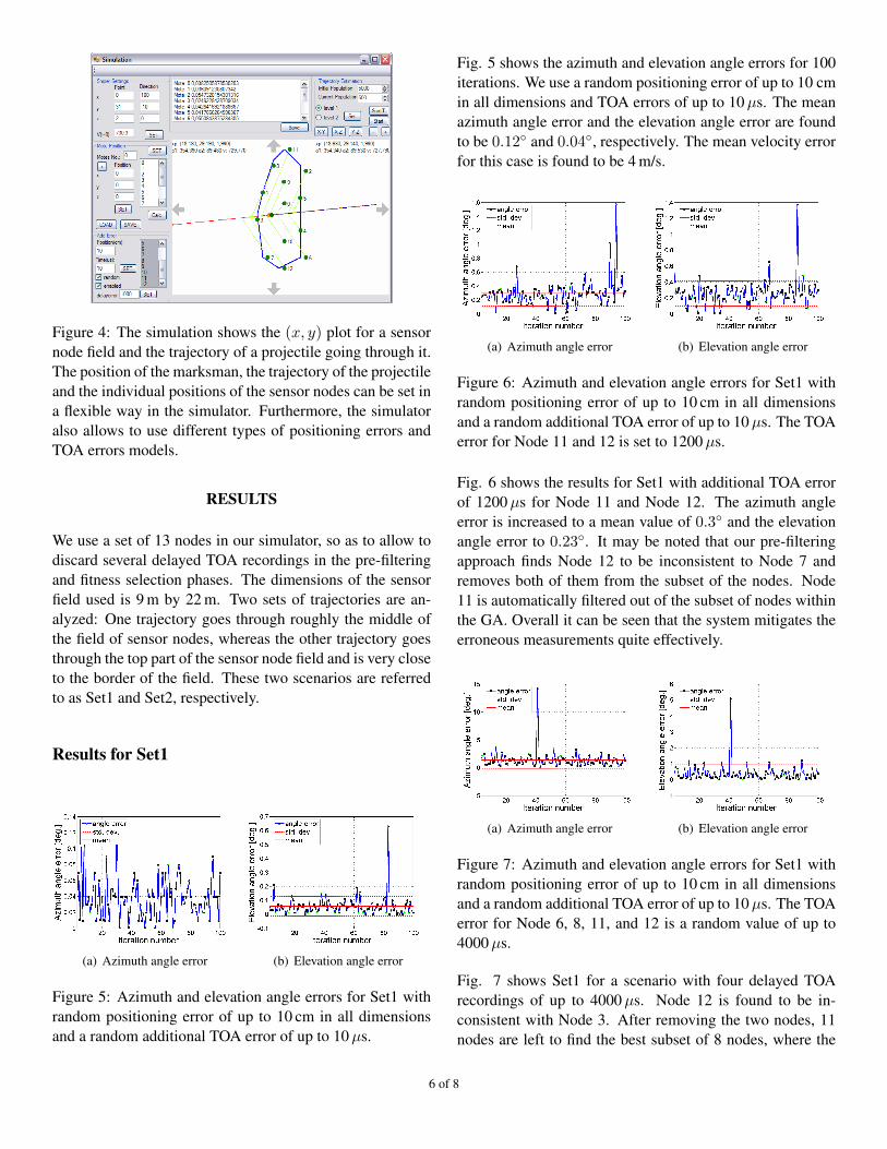
Figure 4: The simulation shows the (x, y) plot for a sensornode field and the trajectory of a projectile going through it.The position of the marksman, the trajectory of the projectileand the individual positions of the sensor nodes can be set ina flexible way in the simulator. Furthermore, the simulatoralso allows to use different types of positioning errors andTOA errors models.
RESULTS
We use a set of 13 nodes in our simulator, so as to allow todiscard several delayed TOA recordings in the pre-filteringand fitness selection phases. The dimensions of the sensorfield used is 9 m by 22 m. Two sets of trajectories are an-alyzed: One trajectory goes through roughly the middle ofthe field of sensor nodes, whereas the other trajectory goesthrough the top part of the sensor node field and is very closeto the border of the field. These two scenarios are referredto as Set1 and Set2, respectively.
Results for Set1
(a) Azimuth angle error (b) Elevation angle error
Figure 5: Azimuth and elevation angle errors for Set1 withrandom positioning error of up to 10 cm in all dimensionsand a random additional TOA error of up to 10 µs.
Fig. 5 shows the azimuth and elevation angle errors for 100iterations. We use a random positioning error of up to 10 cmin all dimensions and TOA errors of up to 10 µs. The meanazimuth angle error and the elevation angle error are foundto be 0.12◦ and 0.04◦, respectively. The mean velocity errorfor this case is found to be 4 m/s.
(a) Azimuth angle error (b) Elevation angle error
Figure 6: Azimuth and elevation angle errors for Set1 withrandom positioning error of up to 10 cm in all dimensionsand a random additional TOA error of up to 10 µs. The TOAerror for Node 11 and 12 is set to 1200 µs.
Fig. 6 shows the results for Set1 with additional TOA errorof 1200 µs for Node 11 and Node 12. The azimuth angleerror is increased to a mean value of 0.3◦ and the elevationangle error to 0.23◦. It may be noted that our pre-filteringapproach finds Node 12 to be inconsistent to Node 7 andremoves both of them from the subset of the nodes. Node11 is automatically filtered out of the subset of nodes withinthe GA. Overall it can be seen that the system mitigates theerroneous measurements quite effectively.
(a) Azimuth angle error (b) Elevation angle error
Figure 7: Azimuth and elevation angle errors for Set1 withrandom positioning error of up to 10 cm in all dimensionsand a random additional TOA error of up to 10 µs. The TOAerror for Node 6, 8, 11, and 12 is a random value of up to4000 µs.
Fig. 7 shows Set1 for a scenario with four delayed TOArecordings of up to 4000 µs. Node 12 is found to be in-consistent with Node 3. After removing the two nodes, 11nodes are left to find the best subset of 8 nodes, where the
6 of 8

other three nodes with increased TOA value have to be re-moved from the subset of nodes. We found an azimuth angleerror of 1.4◦ and the elevation angle error of 0.4◦ The meanvelocity error of the projectile is found to be 19 m/s. How-ever, in iteration number 40 a completely wrong model hasbeen estimated.
Results for Set2
Fig. 8 shows the azimuth and elevation angle errors for Set2scenario. The mean azimuth angle error is found to be 2◦
(a) Azimuth angle error (b) Elevation angle error
Figure 8: Azimuth and elevation angle errors for Set2 withrandom positioning error of up to 10 cm in all dimensionsand a random additional TOA error of up to 10 µs.
larger than the same case of Set1. Since 11 estimations of themodel are above this level, the mean accuracy is not good.Therefore approximately 11 % of the iterations result in awrong model. The elevation angle error is not as large asthe azimuth angle error. In both cases the worst model wasestimated in iteration number 56. In Fig. 9 Node 12 is de-
(a) Azimuth angle error (b) Elevation angle error
Figure 9: Azimuth and elevation angle errors for Set2 withrandom positioning error of up to 10 cm in all dimensionsand a random additional TOA error of up to 10 µs. Node 12is delayed by 3000 µs and inconsistent with Node 7.
layed by 3000 µs. It is inconsistent with Node 7 and bothof the nodes are removed from the set of measurements bythe algorithm. The mean azimuth and the elevation angle
errors are found to be 1.25◦ and 2◦, respectively. The maxi-mum azimuth angle error turns out to be 3.7◦, which is quitesmaller than that of the the previous estimation. Since twonodes had already been removed from the set of nodes, thealgorithm is left with less opportunities to find a subset ofnodes. Although the result looks more stable but the accu-racy of correct models decreases when the number of nodesin the subset are decreased.
Therefore, we observed results in a scenario with two de-layed TOA recordings and in a case when four nodes areremoved from the subset of nodes, the algorithm is unableto find a wrong model by the small number of nodes leftfor the estimation. Fig. 10 shows the results for Set2 with
(a) Azimuth angle error (b) Elevation angle error
Figure 10: Azimuth and elevation angle errors for Set2 withrandom positioning error of up to 10 cm in all dimensionsand a random additional TOA error of up to 10 µs. Node 6and 12 is delayed by 3000 µs and inconsistent with Node 7and 4.
a delayed TOA of Node 12 and Node 6. The Nodes 6, 12,7 and 4 are found inconsistent and therefore, removed fromthe subset of nodes.
By a closed formation of sensor nodes scenario Set2 can beforced to be avoided. Therefore, the performance figures ofthe system designed for protection of an area of interest isrepresented by Set1 which has a good accuracy and errorcompensation.
In real measurements on a small bore shooting stand, wewere limited by the spatial expanse of sensor nodes due tothe lower velocity of a small bore projectile and the fixeddirection of the shooter. Therefore, we observed only onescenario. The nodes were deployed very close to the shooter(within a distance of 6 m). Since the real direction and po-sition of the shooter could not be exactly determined, wedo not present quantitative performance evaluation of ourreal time trajectory estimator. However, it is worth men-tioning that the projectile’s velocity was approximated to be370 m/s, which is quite accurate. Qualitatively, based on vi-sual estimates, the direction estimation was correct.
7 of 8

CONCLUSION AND FUTURE WORK
Our presented WSN based solution is able to accurately es-timate the trajectory and velocity of a supersonic projectile.The gathering of the shockwaves’ TOA values at several po-sitions, is realized using a shockwave detection circuit at-tached to each wireless node, deployed at different positions.The use of an inexpensive circuit board removes the needfor an expensive DSP solution–capable of sampling broad-band acoustic signal at a very high rate. We found from realshooting experiments that the system is able to gather highlyreliable and synchronized TOA readings from sensor nodes.The TOA measurements from various nodes are fused to-gether using a continuous genetic algorithm based data fu-sion framework. We show that our pre-filtering methodand fitness function approach can effectively suppress thenodes with erroneous TOA values. A convex-hull based ini-tial population generation scheme limits the spatial expanseof the search field, whereas the use of tournament selectionscheme generates a stable population of chromosomes andavoids getting stuck into a local maxima. We have describedthe various parts of our data fusion framework in detail. Wealso developed a GUI-based trajectory estimator, which al-lows setting, testing and incorporating various types of noiseand error models.
It takes approximately five seconds to find the direction ofthe marksman on a PC with Intel’s P4 processor clockedat 2.66 GHz and equipped with 512 MB of RAM. An ad-ditional 4–5 s are required to compute an accurate model.The computational bottleneck of our genetic algorithm isthe sorting of chromosomes in every generation. We use thestandard quick sort method for the whole population. Sincethe offspring of chromosomes are not sorted, only 100 chro-mosomes have to be sorted in every generation. There maybe a faster algorithm to sort the added offspring in the pop-ulation.
Using the simulator, we observed that by spatial expanse ofthe WSN, it is possible to receive a shockwave signal hav-ing LOS-component by using enough sensor nodes to deter-mine the model. Furthermore, with greater spatial expanseof the nodes, the probability of estimating a wrong modelis smaller than a deployment scheme with smaller spatialexpanse. This is because model estimation has higher in-fluence near the border of the sensor field as compared tothe middle of the sensor field. We also observed that posi-tioning errors of up to 30 cm do not influence the accuracyof the system very much. Even a few hall errors of sensornodes are successfully detected and removed from the set ofmeasurements.
However, erroneous measurements from several nodes can-not produce an accurate estimation of a model. This is be-cause at least six TOA measurements (in a limited time-frame) from different nodes are needed to estimate themodel. Using the analog circuit board, it is not possible todetect the type of the projectile generating the shockwave.For this purpose, we propose to use a few (approx. 15 % to30 %) DSP based nodes, performing pattern matching analy-sis of the digital signature produced by a projectile at a cer-tain distance from the shooter.
ACKNOWLEDGMENTS
We would like to thank European Union (projectsIST-034963-WASP and IST-004536-RUNES) and RWTHAachen University for the financial support.
REFERENCES
[1] N. Levanon, “Acoustic hit indicator,” IEEE Trans. onAerospace and Electronic Systems, AES-37 (1), 304-309, 2001.
[2] Cannella M. et al., “A novel approach for determiningthe trajectory and speed of a supersonic object,” Mea-surement Science and Technology, vol. 14, pp. 654–662(9), 2003.
[3] A. Ledeczi et al., “Countersniper system for urban war-fare,” TOSN, vol. 1, no. 2, pp. 153–177, 2005.
[4] S. Moroz et al., “Airborne deployment of and recentimprovements to the viper counter sniper system,” Pro-ceedings of the IRIS Specialty Group on Passive Sen-sors, vol. 1, pp. 99–106, 1999.
[5] M. D. Squire, “Location of snipers using three-dimensional infrared/laser tracking,” in Proc. SPIE Vol.2938, p. 311-317, 1997.
[6] B. Kusy et al., “Elapsed time on arrival: A simple andversatile primitive for canonical time synchronisationservices,” Int. J. Ad Hoc and Ubiquitous Computing 1,vol. 4, pp. 239–251, 2006.
[7] R. Graham, “An efficient algorithm for determining theconvex hull of a finite planar set,” Information Process-ing Letters, vol. 1, pp. 132–133, 1972.
[8] B. Miller and D. Goldberg, “Genetic algorithms, tourna-ment selection, and the effects of noise,” Complex Sys-tems, vol. 9, pp. 193–212, 1995.
8 of 8
![Sniper Localization Using Acoustic Sensors Allison Doren Anne Kitzmiller Allie Lockhart Under the Direction of Dr. Arye Nehorai December 11, 2013 [6]](https://static.fdocuments.net/doc/165x107/56649dd85503460f94acde47/sniper-localization-using-acoustic-sensors-allison-doren-anne-kitzmiller-allie.jpg)


![Flexible Timing Simulation of RISC-V Processors with Sniper[SNIPER] Disabling performance models [SNIPER] Leaving ROI after 18.26 seconds OUT: RUN: TraceThread [SNIPER] Simulated 5.0M](https://static.fdocuments.net/doc/165x107/5f9647eee6174c19e44e272f/flexible-timing-simulation-of-risc-v-processors-with-sniper-sniper-disabling-performance.jpg)


