
Snapper 217019BV User Guide
32
Safety Instructions & Operator’s Manual for 21” STEEL DECK WALK MOWERS SERIES 19 MODEL NUMBER EXPLANATION P 21 70 19 B V E SELF-PROPELLED ENGINE OPTION CUTTING WIDTH ENGINE DESIGNATION ENGINE HORSE POWER * SERIES DESIGNATION P – Self Propelled Model 60 – 6.0 HP (Engine Horse Power) 19 - Series Designation 21 – 21” Cutting Width 675 – 6.75 HP (Engine Horse Power) B – Briggs & Stratton V – Overhead Valve 70 – 7.0 HP (Engine Horse Power) KW – Kawasaki Engine E – Electric Start Thank you for buying a SNAPPER Product! Before operating your Walk Behind, read this manual carefully and pay particular attention to the “IMPORTANT SAFETY INSTRUCTIONS” on Pages 2 - 4. Remember that all power equipment can be dangerous if used improperly. Also keep in mind that SAFETY requires careful use in accordance with the operating instructions and common sense. NOTE: Specifications are correct at time of printing and are subject to change without notice. * Actual sustained equipment horsepower will likely be lower due to operating limitations and environmental factors. COPYRIGHT © 2005 SNAPPER – A DIVISION OF SIMPLICITY MFG., INC. ALL RIGHTS RESERVED MANUAL No. 7100366 (I.R. 9/13/2005) TP 100-5084-IR-WB-N MODELS 2167519B P2167519B P217019BV P217019BVE P216019KWV Downloaded from www.Manualslib.com manuals search engine
-
Upload
teresa-carter -
Category
Documents
-
view
25 -
download
0
description
Snapper 217019BV User Guide/Manual
Transcript of Snapper 217019BV User Guide

Safety Instructions & Operator’s Manual for
21” STEEL DECK WALK MOWERS
SERIES 19
MODEL NUMBER EXPLANATION
P 21 70 19 B V E SELF-PROPELLED ENGINE OPTION CUTTING WIDTH ENGINE DESIGNATION ENGINE HORSE POWER * SERIES DESIGNATION P – Self Propelled Model 60 – 6.0 HP (Engine Horse Power) 19 - Series Designation 21 – 21” Cutting Width 675 – 6.75 HP (Engine Horse Power) B – Briggs & Stratton V – Overhead Valve 70 – 7.0 HP (Engine Horse Power) KW – Kawasaki Engine E – Electric Start
Thank you for buying a SNAPPER Product! Before operating your Walk Behind, read this manual carefully and pay particular attention to the “IMPORTANT SAFETY INSTRUCTIONS” on Pages 2 - 4. Remember that all power equipment can be dangerous if used improperly. Also keep in mind that SAFETY requires careful use in accordance with the operating instructions and common sense. NOTE: Specifications are correct at time of printing and are subject to change without notice. * Actual sustained equipment horsepower will likely be lower due to operating limitations and environmental factors. COPYRIGHT © 2005 SNAPPER – A DIVISION OF SIMPLICITY MFG., INC. ALL RIGHTS RESERVED
MANUAL No. 7100366 (I.R. 9/13/2005) TP 100-5084-IR-WB-N
MODELS 2167519B
P2167519B P217019BV
P217019BVE P216019KWV
Downloaded from www.Manualslib.com manuals search engine

2
IMPORTANT SAFETY INSTRUCTIONS WARNING: This powerful cutting machine is capable of amputating hands and feet and can throw objects that can cause injury and damage! Failure to comply with the following SAFETY instructions could result in serious injury or death to the operator or other persons. The owner of the machine must understand these instructions and must allow only persons who understand these instructions to operate machine. Each person operating the machine must be of sound mind and body and must not be under the influence of any substance, which might impair vision, dexterity or judgment. If you have any questions pertaining to your machine which your dealer cannot answer to your satisfaction, call or write the Customer Service Department at SNAPPER, McDonough, Georgia 30253. Phone: (1-800-935-2967). PROTECTION FOR CHILDREN Tragic accidents can occur if the operator is not alert to the presence of children. Children are often attracted to the machine and the mowing activity. Never assume that children will remain where you last saw them.
1. KEEP children out of the mowing area and under the watchful care of a responsible adult other than the operator.
2. DO NOT allow children in yard when machine is operated and turn machine OFF if anyone enters the area.
3. DO NOT allow pre-teenage children to operate machine.
4. ALLOW only responsible adults & teenagers with mature judgment under close adult supervision to operate machine.
5. DO NOT pull mower backwards unless absolutely necessary. LOOK and SEE behind and down for children, pets and hazards before and while backing.
6. USE EXTRA CARE when approaching blind corners, shrubs, trees, or other objects that may obscure vision.
SLOPE OPERATION 1. Slopes are a major factor related to slip and fall
accidents, which can result in severe injury. All slopes require extra caution. If you feel uneasy on a slope, DO NOT mow it.
2. Mow across slopes, never up-and-down. Exercise extreme CAUTION when changing directions on slopes. DO NOT mow steep slopes or other areas where stability or traction is in doubt.
3. Use extra care with grass catchers or other attachments; these affect the handling and the stability of the machine.
PREPARATION 1. Read, understand, and follow instructions and
warnings in this manual and on the mower, engine and attachments. Know the controls and the proper use of the mower before starting.
2. Only mature, responsible persons shall operate the machine and only after proper instruction.
PREPARATION (Continued From Previous Column)
3. Data indicates that operators age 60 and above, are involved in a large percentage of mower-related injuries. These operators should evaluate their ability to operate the mower safely enough to protect themselves and others from serious injury.
4. Handle fuel with extra care. Fuels are flammable and vapors are explosive. Use only an approved fuel container. DO NOT remove fuel cap or add fuel with engine running. Add fuel outdoors only with engine stopped and cool. Clean spilled fuel and oil from machine. DO NOT smoke.
5. Check the area to be mowed and remove all objects such as toys, wire, rocks, limbs and other objects that could cause injury if thrown by blade or interfere with mowing. Also note the location of holes, stumps, and other possible hazards.
6. Keep people and pets out of the mowing area. Immediately, STOP Blade, Stop engine and Stop mower if anyone enters the area.
7. Check shields, deflectors, switches, blade controls and other safety devices frequently for proper operation and location.
8. Make sure all safety decals are clearly legible. Replace if damaged.
9. Protect yourself when mowing and wear safety glasses, long pants and substantial footwear. DO NOT mow barefooted or with sandals.
10. Know how to STOP blade and engine quickly in preparation for emergencies.
11. Use extra care when loading or unloading the machine into a trailer or truck.
12. Check grass catcher components frequently for signs of wear or deterioration and replace as needed to prevent injury from thrown objects going through weak or torn spots.
SAFE HANDLING OF GASOLINE To avoid personal injury or property damage, use extreme care in handling gasoline. Gasoline is extremely flammable and the vapors are explosive 1. Extinguish all cigarettes, cigars, pipes and other
sources of ignition. 2. Use only an approved fuel container.
Downloaded from www.Manualslib.com manuals search engine

3
IMPORTANT SAFETY INSTRUCTIONS SAFE HANDLING OF GASOLINE (Continued From Previous Page) 3. DO NOT remove fuel cap or add fuel with the engine
running. Allow the engine to cool before refueling. 4. DO NOT refuel the machine indoors. 5. DO NOT store the machine or fuel container inside
where there is an open flame, spark or pilot light such as on a water heater or other appliances.
6. DO NOT fill fuel containers inside a vehicle or on a truck or trailer bed with a plastic liner. Always place the containers on the ground away from the vehicle before filling.
7. Remove gas-powered equipment from the vehicle or trailer and refuel it on the ground. If this is not possible, then refuel equipment using a portable container, rather than a gasoline dispenser nozzle.
8. DO NOT start gas powered equipment in enclosed vehicles or trailers.
9. Keep the nozzle in contact with the rim of the fuel tank or container opening at all times until fueling is complete. DO NOT use a nozzle lock-open device
10. If fuel is spilled on clothing, change clothing immediately.
11. DO NOT overfill a fuel tank. Replace fuel cap and tighten securely.
OPERATION 1. DO NOT put hands or feet near or under rotating
parts. Keep clear of discharge area while engine is running.
2. STOP engine when crossing gravel drives, walks, or roads, and under any conditions where thrown objects might be a hazard.
3. Mow only in daylight or good artificial light. 4. DO NOT operate mower while under the influence of
alcohol or drugs. 5. After striking a foreign object or if mower vibrates
abnormally, STOP the engine, disconnect and secure spark plug wire. Inspect the mower for any damage and repair the damage before starting.
6. DO NOT mow near drop offs, ditches or embankments. Operator could lose footing or balance.
7. STAY ALERT for holes and other hidden hazards. Tall grass can hide obstacles. Keep away from ditches, washouts, culverts, fences and protruding objects.
8. DO NOT mow on wet grass. Always be sure of your footing. Keep a firm hold on the handle and walk, never run. Slipping could cause injury.
9. ALWAYS stay behind handle when engine (motor) is running.
10. DO NOT leave the machine with the engine running. STOP BLADE and STOP ENGINE before leaving the operators position for any reason.
OPERATION (Continued From Previous Column) 11. Before cleaning, repairing or inspecting make
certain engine, blade and all moving parts have STOPPED. Disconnect and secure spark plug wire away from plug to prevent accidental starting.
12. STOP engine and wait until the blade comes to complete STOP before removing grass bag and/or clearing grass.
13. DO NOT operate mower without the entire grass catcher, discharge guard, rear guard or other safety devices in place and working. DO NOT point discharge at people, passing cars, windows or doors.
14. DO NOT discharge material against a wall or obstruction. Material may ricochet back towards the operator.
15. Slow down before turning. 16. Watch out for traffic when near or crossing
roadways. 17. DO NOT operate engine in enclosed areas. Engine
exhaust gases contain carbon monoxide, a deadly poison.
18. Only use accessories approved by the manufacturer. See manufacturer’s instructions for proper operation and installation of accessories.
MAINTENANCE AND STORAGE 1. DO NOT store mower or fuel container inside where
fumes may reach an open flame, spark or pilot light such as in a water heater, furnace, clothes dryer or other gas appliance. Allow engine to cool before storing machine in an enclosure. Store fuel container out of reach of children in a well ventilated, unoccupied building.
2. Keep mower and engine free of grass, leaves or excess grease to reduce fire hazard and engine overheating.
3. When draining fuel tank, drain fuel into an approved container outdoors and away from open flame.
4. Keep all bolts, especially blade bolts, nuts and screws properly tight. Check that all cotter pins are in proper position.
5. Always provide adequate ventilation when running engine. Engine exhaust gases contain carbon monoxide, a deadly poison.
6. Service engine and make adjustments only when engine is stopped. Removed spark plug wire from spark plug and secure wire away from spark plug to prevent accidental starting.
7. DO NOT change engine governor speed settings or overspeed engine.
8. Check grass bag assembly frequently for wear or deterioration to avoid thrown objects and exposure to moving parts. Replace with new bag if loose seams or tears are evident. Replace slider or bag adapter if broken or cracked.
Downloaded from www.Manualslib.com manuals search engine

4
IMPORTANT SAFETY INSTRUCTIONS MAINTENANCE AND STORAGE (Continued From Previous Page) 9. Mower blades are sharp and can cut. Wrap the
blades or wear heavy leather gloves and use CAUTION when handling them.
10. DO NOT test for spark by grounding spark plug next to spark plug hole; spark plug could ignite gas exiting engine.
11. Have machine serviced by an authorized SNAPPER dealer at least once a year and have the dealer install any new safety devices.
12. Use only genuine SNAPPER replacement parts to assure that original standards are maintained.
Downloaded from www.Manualslib.com manuals search engine
5
TABLE OF CONTENTS
IMPORTANT SAFETY INSTRUCTIONS...................................................................... 2 - 4 TABLE OF CONTENTS......................................................................................................5 SECTION 1 - FAMILIARIZATION.......................................................................................6 SECTION 2 - OPERATING INSTRUCTIONS............................................................... 7-11 Pre-start Checklist................................................................................................7 Starting & Stopping Engine & Blade .............................................................. 7-8 Starting & Stopping Wheel Drive ........................................................................8 Handle Height Adjustment ..................................................................................8 Cutting Height Adjustment.............................................................................. 8-9 Installation of Grass Bag ............................................................................... 9-11 Installation of Discharge Deflector...................................................................11 Installation of Recycling Cover.........................................................................11 Recycling Operation...........................................................................................11 SECTION 3 - MAINTENANCE INSTRUCTIONS ....................................................... 12-13 Change Engine Oil..............................................................................................12 Check Transmission Grease.............................................................................12 Check Mower Blade ...........................................................................................13 Check Engine Drive Belt ....................................................................................13 Check Transmission Poly-V Belt ......................................................................13 Service - Annually ..............................................................................................13 Engine ..............................................................................................................13 Air Filter............................................................................................................13 Engine Oil.........................................................................................................13 Storage Procedure .............................................................................................13 SECTION 4 - ADJUSTMENTS AND REPAIR............................................................ 14-21 Mower Blade Replacement................................................................................14 Blade Sharpening......................................................................................... 14-15 Wheel Drive Control Adjustment ......................................................................15 Driven and Drive Disc Service .................................................................... 16-19 Cleaning Drive Disc and Driven Disc ............................................................16 Drive Spring Repair/Replacement .................................................................16 Driven Disc Adjustment............................................................................ 16-17 Driven Disc Replacement ......................................................................... 17-18 Driven Disc Bearing Replacement ................................................................18 Hex Shaft Bearing Replacement....................................................................19 Belt Service ................................................................................................... 19-20 Engine Drive Belt Replacement............................................................... 19-20 Transmission Poly-V Belt Replacement .......................................................20 Battery Service ...................................................................................................21 TROUBLESHOOTING......................................................................................................22 SERVICE SCHEDULE......................................................................................................23 Maintenance/Replacement Parts ......................................................................23 WARRANTY......................................................................................................................24 PRIMARY MAINTENANCE ........................................................................................ 25-28 PRODUCT REGISTRATION FORM.................................................................................29
! IMPORTANT !
The figures and illustrations in this manual are provided for reference only and may differ from your specific model. Contact your local SNAPPER dealer if you have questions.
Downloaded from www.Manualslib.com manuals search engine
6
Section 1 - FAMILIARIZATION
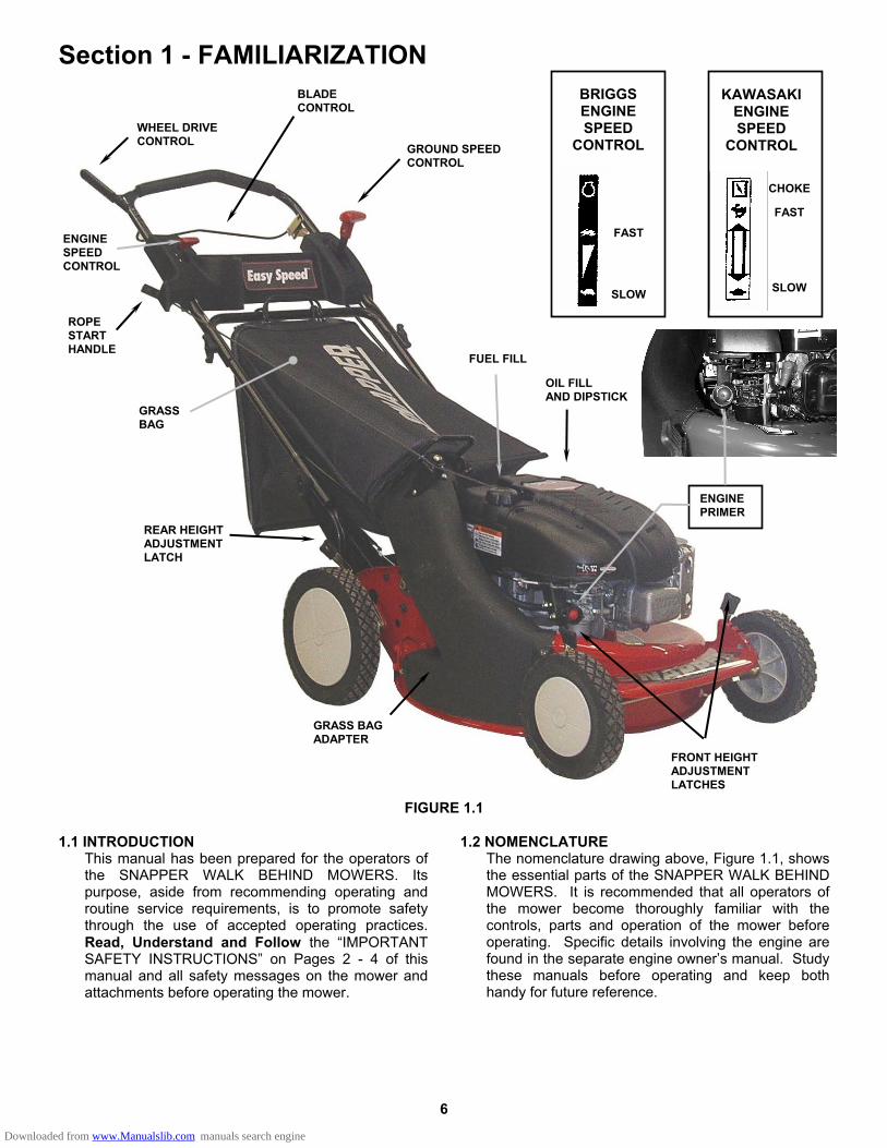
FIGURE 1.1 1.1 INTRODUCTION
This manual has been prepared for the operators of the SNAPPER WALK BEHIND MOWERS. Its purpose, aside from recommending operating and routine service requirements, is to promote safety through the use of accepted operating practices. Read, Understand and Follow the “IMPORTANT SAFETY INSTRUCTIONS” on Pages 2 - 4 of this manual and all safety messages on the mower and attachments before operating the mower.
1.2 NOMENCLATURE The nomenclature drawing above, Figure 1.1, shows the essential parts of the SNAPPER WALK BEHIND MOWERS. It is recommended that all operators of the mower become thoroughly familiar with the controls, parts and operation of the mower before operating. Specific details involving the engine are found in the separate engine owner’s manual. Study these manuals before operating and keep both handy for future reference.
WHEEL DRIVE CONTROL
BLADE CONTROL
GROUND SPEED CONTROL
ROPE START HANDLE
GRASS BAG
REAR HEIGHT ADJUSTMENT LATCH
GRASS BAG ADAPTER
FRONT HEIGHT ADJUSTMENT LATCHES
OIL FILL AND DIPSTICK
FUEL FILL
ENGINE PRIMER
FAST
SLOW
KAWASAKI ENGINE SPEED
CONTROL
CHOKE
FAST
SLOW
BRIGGS ENGINE SPEED
CONTROL
ENGINE SPEED CONTROL
Downloaded from www.Manualslib.com manuals search engine
7
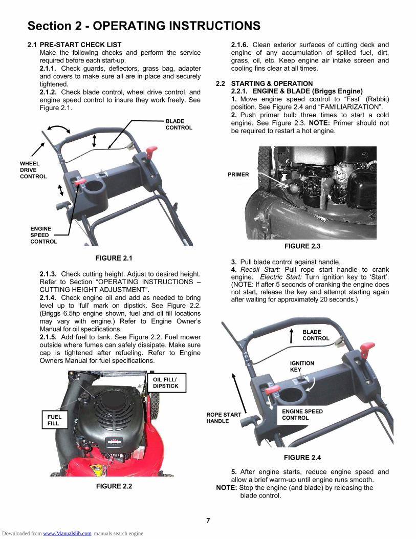
Section 2 - OPERATING INSTRUCTIONS 2.1 PRE-START CHECK LIST
Make the following checks and perform the service required before each start-up. 2.1.1. Check guards, deflectors, grass bag, adapter and covers to make sure all are in place and securely tightened. 2.1.2. Check blade control, wheel drive control, and engine speed control to insure they work freely. See Figure 2.1.
FIGURE 2.1
2.1.3. Check cutting height. Adjust to desired height. Refer to Section “OPERATING INSTRUCTIONS – CUTTING HEIGHT ADJUSTMENT”. 2.1.4. Check engine oil and add as needed to bring level up to ‘full’ mark on dipstick. See Figure 2.2. (Briggs 6.5hp engine shown, fuel and oil fill locations may vary with engine.) Refer to Engine Owner’s Manual for oil specifications. 2.1.5. Add fuel to tank. See Figure 2.2. Fuel mower outside where fumes can safely dissipate. Make sure cap is tightened after refueling. Refer to Engine Owners Manual for fuel specifications.
FIGURE 2.2
2.1.6. Clean exterior surfaces of cutting deck and engine of any accumulation of spilled fuel, dirt, grass, oil, etc. Keep engine air intake screen and cooling fins clear at all times.
2.2 STARTING & OPERATION
2.2.1. ENGINE & BLADE (Briggs Engine) 1. Move engine speed control to “Fast” (Rabbit) position. See Figure 2.4 and “FAMILIARIZATION”. 2. Push primer bulb three times to start a cold engine. See Figure 2.3. NOTE: Primer should not be required to restart a hot engine.
FIGURE 2.3 3. Pull blade control against handle. 4. Recoil Start: Pull rope start handle to crank engine. Electric Start: Turn ignition key to ‘Start’. (NOTE: If after 5 seconds of cranking the engine does not start, release the key and attempt starting again after waiting for approximately 20 seconds.)
FIGURE 2.4
5. After engine starts, reduce engine speed and allow a brief warm-up until engine runs smooth.
NOTE: Stop the engine (and blade) by releasing the blade control.
WHEEL DRIVE CONTROL
BLADE CONTROL
ENGINE SPEED CONTROL
PRIMER
OIL FILL/ DIPSTICK
FUEL FILL
BLADE CONTROL
ROPE STARTHANDLE
ENGINE SPEED CONTROL
IGNITION KEY
Downloaded from www.Manualslib.com manuals search engine
8
Section 2 - OPERATING INSTRUCTIONS 2.2 STARTING & OPERATION
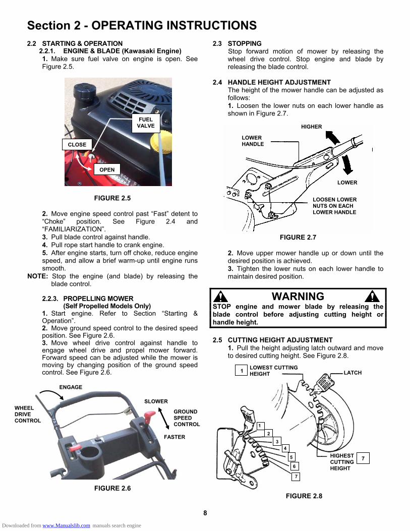
2.2.1. ENGINE & BLADE (Kawasaki Engine) 1. Make sure fuel valve on engine is open. See Figure 2.5.
FIGURE 2.5
2. Move engine speed control past “Fast” detent to “Choke” position. See Figure 2.4 and “FAMILIARIZATION”. 3. Pull blade control against handle. 4. Pull rope start handle to crank engine. 5. After engine starts, turn off choke, reduce engine speed, and allow a brief warm-up until engine runs smooth.
NOTE: Stop the engine (and blade) by releasing the blade control.
2.2.3. PROPELLING MOWER (Self Propelled Models Only) 1. Start engine. Refer to Section “Starting & Operation”. 2. Move ground speed control to the desired speed position. See Figure 2.6. 3. Move wheel drive control against handle to engage wheel drive and propel mower forward. Forward speed can be adjusted while the mower is moving by changing position of the ground speed control. See Figure 2.6.
FIGURE 2.6
2.3 STOPPING Stop forward motion of mower by releasing the wheel drive control. Stop engine and blade by releasing the blade control.
2.4 HANDLE HEIGHT ADJUSTMENT The height of the mower handle can be adjusted as follows: 1. Loosen the lower nuts on each lower handle as shown in Figure 2.7.
FIGURE 2.7
2. Move upper mower handle up or down until the desired position is achieved. 3. Tighten the lower nuts on each lower handle to maintain desired position.
WARNING STOP engine and mower blade by releasing the blade control before adjusting cutting height or handle height. 2.5 CUTTING HEIGHT ADJUSTMENT
1. Pull the height adjusting latch outward and move to desired cutting height. See Figure 2.8.
FIGURE 2.8
GROUND SPEED CONTROL
WHEEL DRIVE CONTROL
ENGAGE
FUEL VALVE
OPEN
CLOSE
FASTER
SLOWER
HIGHER
LOWER
LOOSEN LOWER NUTS ON EACH LOWER HANDLE
LOWER HANDLE
LOWEST CUTTING HEIGHT1 LATCH
HIGHEST CUTTING HEIGHT
7
21
3 4
5
6
7
Downloaded from www.Manualslib.com manuals search engine
9
Section 2 - OPERATING INSTRUCTIONS
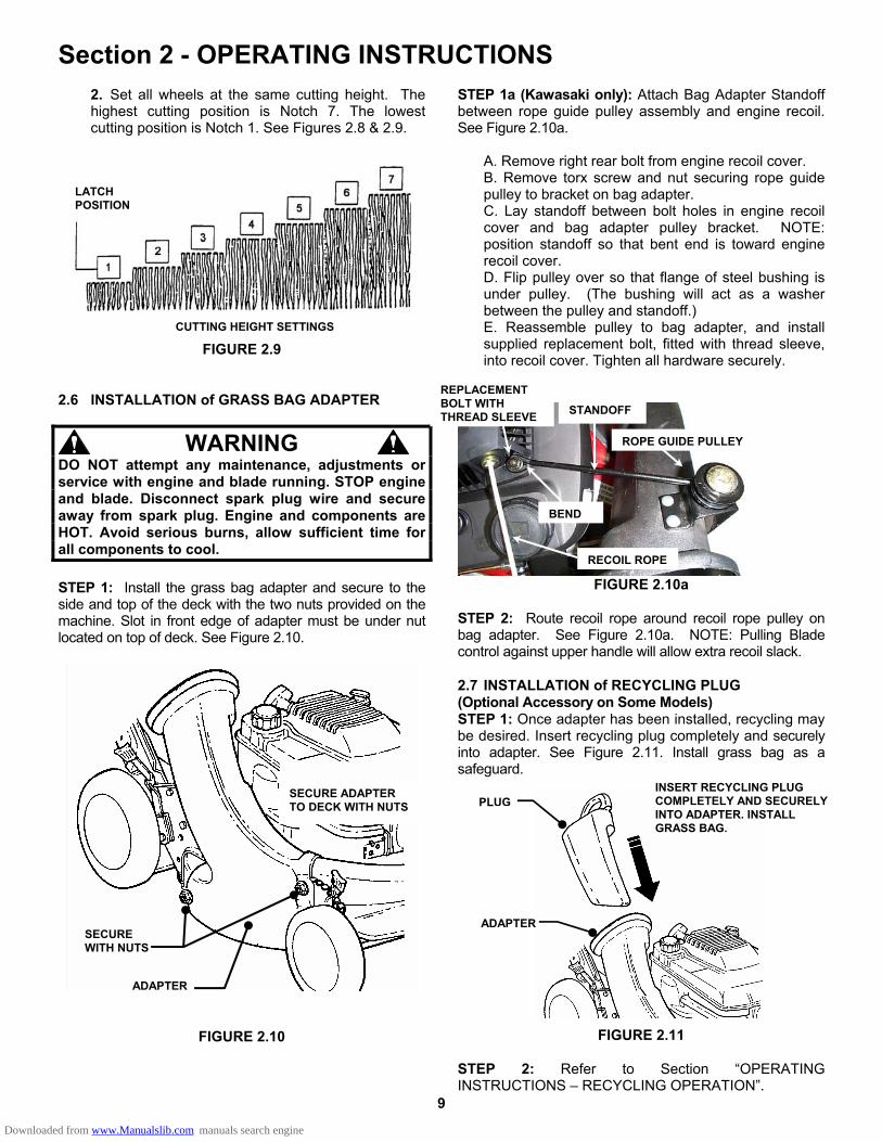
2. Set all wheels at the same cutting height. The highest cutting position is Notch 7. The lowest cutting position is Notch 1. See Figures 2.8 & 2.9.
FIGURE 2.9 2.6 INSTALLATION of GRASS BAG ADAPTER
WARNING DO NOT attempt any maintenance, adjustments or service with engine and blade running. STOP engine and blade. Disconnect spark plug wire and secure away from spark plug. Engine and components are HOT. Avoid serious burns, allow sufficient time for all components to cool. STEP 1: Install the grass bag adapter and secure to the side and top of the deck with the two nuts provided on the machine. Slot in front edge of adapter must be under nut located on top of deck. See Figure 2.10.
FIGURE 2.10
STEP 1a (Kawasaki only): Attach Bag Adapter Standoff between rope guide pulley assembly and engine recoil. See Figure 2.10a.
A. Remove right rear bolt from engine recoil cover. B. Remove torx screw and nut securing rope guide pulley to bracket on bag adapter. C. Lay standoff between bolt holes in engine recoil cover and bag adapter pulley bracket. NOTE: position standoff so that bent end is toward engine recoil cover. D. Flip pulley over so that flange of steel bushing is under pulley. (The bushing will act as a washer between the pulley and standoff.) E. Reassemble pulley to bag adapter, and install supplied replacement bolt, fitted with thread sleeve, into recoil cover. Tighten all hardware securely.
FIGURE 2.10a
STEP 2: Route recoil rope around recoil rope pulley on bag adapter. See Figure 2.10a. NOTE: Pulling Blade control against upper handle will allow extra recoil slack. 2.7 INSTALLATION of RECYCLING PLUG (Optional Accessory on Some Models) STEP 1: Once adapter has been installed, recycling may be desired. Insert recycling plug completely and securely into adapter. See Figure 2.11. Install grass bag as a safeguard.
FIGURE 2.11 STEP 2: Refer to Section “OPERATING INSTRUCTIONS – RECYCLING OPERATION”.
LATCH POSITION
CUTTING HEIGHT SETTINGS
SECURE ADAPTER TO DECK WITH NUTS
SECURE WITH NUTS
ADAPTER
INSERT RECYCLING PLUG COMPLETELY AND SECURELY INTO ADAPTER. INSTALL GRASS BAG.
ADAPTER
PLUG
REPLACEMENT BOLT WITH THREAD SLEEVE
BEND
STANDOFF
ROPE GUIDE PULLEY
RECOIL ROPE
Downloaded from www.Manualslib.com manuals search engine
10
Section 2 - OPERATING INSTRUCTIONS
WARNING DO NOT attempt any maintenance, adjustments or service with engine and blade running. STOP engine and blade. Disconnect spark plug wire and secure away from spark plug. Engine and components are HOT. Avoid serious burns, allow sufficient time for all components to cool. 2.8 INSTALLATION of GRASS BAG (Door Type Bag)
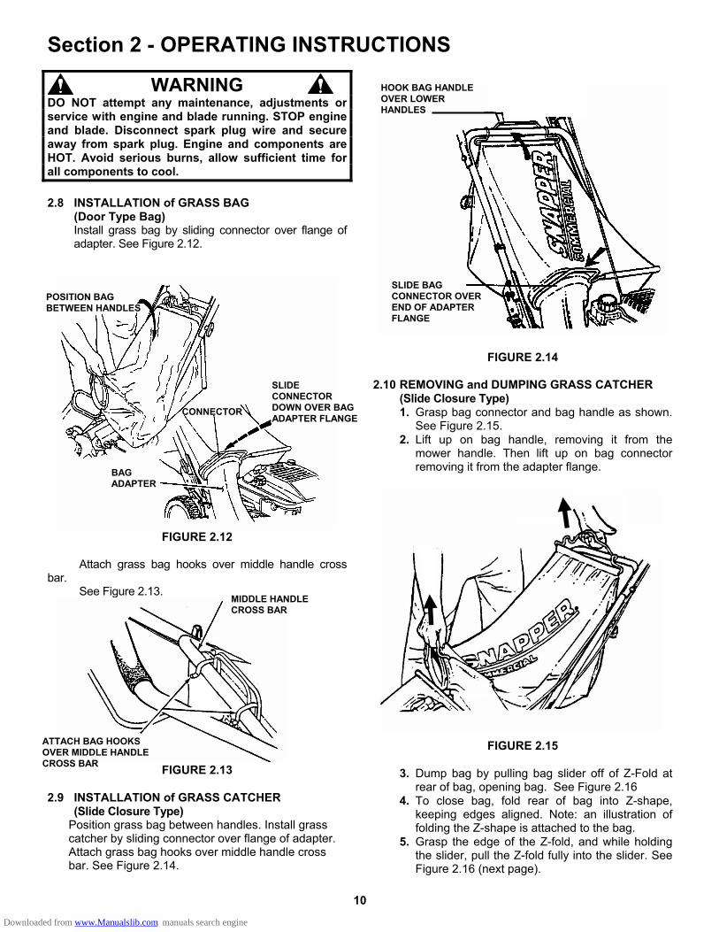
Install grass bag by sliding connector over flange of adapter. See Figure 2.12.
FIGURE 2.12
Attach grass bag hooks over middle handle cross bar. See Figure 2.13.
FIGURE 2.13
2.9 INSTALLATION of GRASS CATCHER
(Slide Closure Type) Position grass bag between handles. Install grass catcher by sliding connector over flange of adapter. Attach grass bag hooks over middle handle cross bar. See Figure 2.14.
FIGURE 2.14 2.10 REMOVING and DUMPING GRASS CATCHER (Slide Closure Type)
1. Grasp bag connector and bag handle as shown. See Figure 2.15.
2. Lift up on bag handle, removing it from the mower handle. Then lift up on bag connector removing it from the adapter flange.
FIGURE 2.15
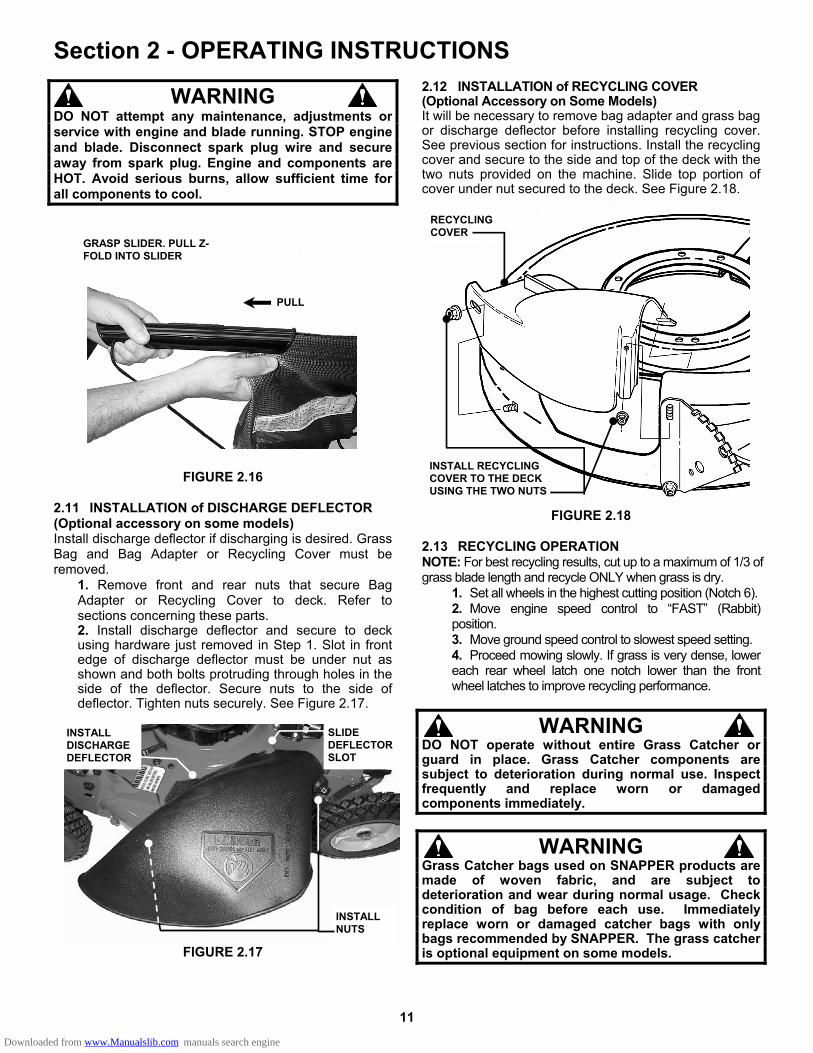
3. Dump bag by pulling bag slider off of Z-Fold at
rear of bag, opening bag. See Figure 2.16 4. To close bag, fold rear of bag into Z-shape,
keeping edges aligned. Note: an illustration of folding the Z-shape is attached to the bag.
5. Grasp the edge of the Z-fold, and while holding the slider, pull the Z-fold fully into the slider. See Figure 2.16 (next page).
POSITION BAG BETWEEN HANDLES
SLIDE CONNECTOR DOWN OVER BAG ADAPTER FLANGE
BAG ADAPTER
CONNECTOR
SLIDE BAG CONNECTOR OVER END OF ADAPTER FLANGE
ATTACH BAG HOOKS OVER MIDDLE HANDLE CROSS BAR
MIDDLE HANDLE CROSS BAR
HOOK BAG HANDLE OVER LOWER HANDLES
Downloaded from www.Manualslib.com manuals search engine
11
Section 2 - OPERATING INSTRUCTIONS
WARNING DO NOT attempt any maintenance, adjustments or service with engine and blade running. STOP engine and blade. Disconnect spark plug wire and secure away from spark plug. Engine and components are HOT. Avoid serious burns, allow sufficient time for all components to cool.
FIGURE 2.16 2.11 INSTALLATION of DISCHARGE DEFLECTOR (Optional accessory on some models) Install discharge deflector if discharging is desired. Grass Bag and Bag Adapter or Recycling Cover must be removed.
1. Remove front and rear nuts that secure Bag Adapter or Recycling Cover to deck. Refer to sections concerning these parts. 2. Install discharge deflector and secure to deck using hardware just removed in Step 1. Slot in front edge of discharge deflector must be under nut as shown and both bolts protruding through holes in the side of the deflector. Secure nuts to the side of deflector. Tighten nuts securely. See Figure 2.17.
FIGURE 2.17
2.12 INSTALLATION of RECYCLING COVER (Optional Accessory on Some Models) It will be necessary to remove bag adapter and grass bag or discharge deflector before installing recycling cover. See previous section for instructions. Install the recycling cover and secure to the side and top of the deck with the two nuts provided on the machine. Slide top portion of cover under nut secured to the deck. See Figure 2.18.
FIGURE 2.18 2.13 RECYCLING OPERATION NOTE: For best recycling results, cut up to a maximum of 1/3 of grass blade length and recycle ONLY when grass is dry.
1. Set all wheels in the highest cutting position (Notch 6). 2. Move engine speed control to “FAST” (Rabbit) position. 3. Move ground speed control to slowest speed setting. 4. Proceed mowing slowly. If grass is very dense, lower each rear wheel latch one notch lower than the front wheel latches to improve recycling performance.
WARNING DO NOT operate without entire Grass Catcher or guard in place. Grass Catcher components are subject to deterioration during normal use. Inspect frequently and replace worn or damaged components immediately.
WARNING Grass Catcher bags used on SNAPPER products are made of woven fabric, and are subject to deterioration and wear during normal usage. Check condition of bag before each use. Immediately replace worn or damaged catcher bags with only bags recommended by SNAPPER. The grass catcher is optional equipment on some models.
GRASP SLIDER. PULL Z-FOLD INTO SLIDER
PULL
INSTALL DISCHARGE DEFLECTOR
INSTALL NUTS
SLIDE DEFLECTOR SLOT
INSTALL RECYCLING COVER TO THE DECK USING THE TWO NUTS
RECYCLING COVER
Downloaded from www.Manualslib.com manuals search engine
12
Section 3 – MAINTENANCE 3.1 INTRODUCTION
To retain the quality of the mower, use genuine SNAPPER replacement parts only. Contact a local SNAPPER dealer for parts and service assistance. For the correct part or information for a particular mower, always mention model and serial number.
WARNING DO NOT attempt any maintenance, adjustments or service with engine and blade running. STOP engine and blade. Disconnect spark plug wire and secure away from spark plug. Engine and components are HOT. Avoid serious burns, allow sufficient time for all components to cool. 3.2 SERVICE - AFTER FIRST 5 HOURS
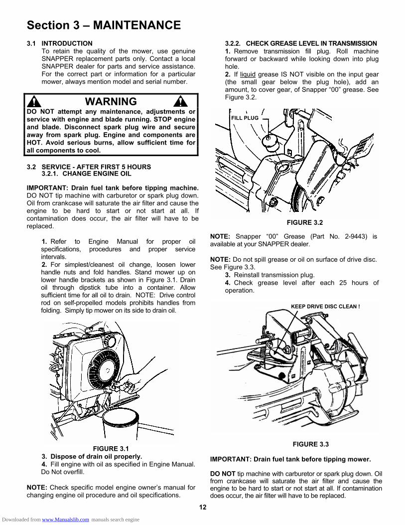
3.2.1. CHANGE ENGINE OIL
IMPORTANT: Drain fuel tank before tipping machine. DO NOT tip machine with carburetor or spark plug down. Oil from crankcase will saturate the air filter and cause the engine to be hard to start or not start at all. If contamination does occur, the air filter will have to be replaced.
1. Refer to Engine Manual for proper oil specifications, procedures and proper service intervals. 2. For simplest/cleanest oil change, loosen lower handle nuts and fold handles. Stand mower up on lower handle brackets as shown in Figure 3.1. Drain oil through dipstick tube into a container. Allow sufficient time for all oil to drain. NOTE: Drive control rod on self-propelled models prohibits handles from folding. Simply tip mower on its side to drain oil.
FIGURE 3.1
3. Dispose of drain oil properly. 4. Fill engine with oil as specified in Engine Manual. Do Not overfill.
NOTE: Check specific model engine owner’s manual for changing engine oil procedure and oil specifications.
3.2.2. CHECK GREASE LEVEL IN TRANSMISSION 1. Remove transmission fill plug. Roll machine forward or backward while looking down into plug hole. 2. If liquid grease IS NOT visible on the input gear (the small gear below the plug hole), add an amount, to cover gear, of Snapper “00” grease. See Figure 3.2.
FIGURE 3.2
NOTE: Snapper “00” Grease (Part No. 2-9443) is available at your SNAPPER dealer.
NOTE: Do not spill grease or oil on surface of drive disc. See Figure 3.3.
3. Reinstall transmission plug. 4. Check grease level after each 25 hours of operation.
FIGURE 3.3
IMPORTANT: Drain fuel tank before tipping mower. DO NOT tip machine with carburetor or spark plug down. Oil from crankcase will saturate the air filter and cause the engine to be hard to start or not start at all. If contamination does occur, the air filter will have to be replaced.
FILL PLUG
KEEP DRIVE DISC CLEAN !
Downloaded from www.Manualslib.com manuals search engine
13
Section 3 – MAINTENANCE
WARNING DO NOT attempt any maintenance, adjustments or service with engine and blade running. STOP engine and blade. Disconnect spark plug wire and secure away from spark plug. Engine and components are HOT. Avoid serious burns, allow sufficient time for all components to cool. Wear heavy leather gloves when handling or working around cutting blades. Blades are extremely sharp and can cause severe injury.
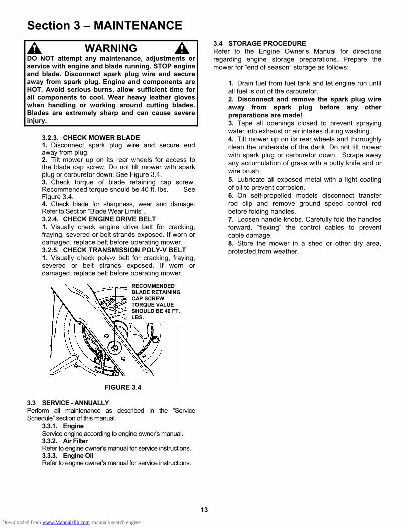
3.2.3. CHECK MOWER BLADE 1. Disconnect spark plug wire and secure end away from plug. 2. Tilt mower up on its rear wheels for access to the blade cap screw. Do not tilt mower with spark plug or carburetor down. See Figure 3.4. 3. Check torque of blade retaining cap screw. Recommended torque should be 40 ft. lbs. See Figure 3.4. 4. Check blade for sharpness, wear and damage. Refer to Section “Blade Wear Limits”. 3.2.4. CHECK ENGINE DRIVE BELT 1. Visually check engine drive belt for cracking, fraying, severed or belt strands exposed. If worn or damaged, replace belt before operating mower. 3.2.5. CHECK TRANSMISSION POLY-V BELT 1. Visually check poly-v belt for cracking, fraying, severed or belt strands exposed. If worn or damaged, replace belt before operating mower.
FIGURE 3.4
3.3 SERVICE - ANNUALLY Perform all maintenance as described in the “Service Schedule” section of this manual.
3.3.1. Engine Service engine according to engine owner’s manual. 3.3.2. Air Filter Refer to engine owner’s manual for service instructions. 3.3.3. Engine Oil Refer to engine owner’s manual for service instructions.
3.4 STORAGE PROCEDURE Refer to the Engine Owner’s Manual for directions regarding engine storage preparations. Prepare the mower for “end of season” storage as follows:
1. Drain fuel from fuel tank and let engine run until all fuel is out of the carburetor. 2. Disconnect and remove the spark plug wire away from spark plug before any other preparations are made! 3. Tape all openings closed to prevent spraying water into exhaust or air intakes during washing. 4. Tilt mower up on its rear wheels and thoroughly clean the underside of the deck. Do not tilt mower with spark plug or carburetor down. Scrape away any accumulation of grass with a putty knife and or wire brush. 5. Lubricate all exposed metal with a light coating of oil to prevent corrosion. 6. On self-propelled models disconnect transfer rod clip and remove ground speed control rod before folding handles. 7. Loosen handle knobs. Carefully fold the handles forward, “flexing” the control cables to prevent cable damage. 8. Store the mower in a shed or other dry area, protected from weather.
RECOMMENDED BLADE RETAINING CAP SCREW TORQUE VALUE SHOULD BE 40 FT. LBS.
Downloaded from www.Manualslib.com manuals search engine
14
Section 4 - REPAIR & ADJUSTMENTS
WARNING DO NOT attempt any maintenance, adjustments or service with engine and blade running. STOP engine and blade. Disconnect spark plug wire and secure away from spark plug. Engine and components are HOT. Avoid serious burns, allow sufficient time for all components to cool. Wear heavy leather gloves when handling or working around cutting blades. Blades are extremely sharp and can cause severe injury.
4.1 MOWER BLADE REPLACEMENT
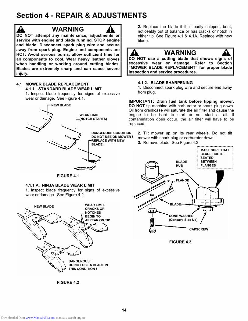
4.1.1. STANDARD BLADE WEAR LIMIT 1. Inspect blade frequently for signs of excessive wear or damage. See Figure 4.1.
FIGURE 4.1
4.1.1.A. NINJA BLADE WEAR LIMIT 1. Inspect blade frequently for signs of excessive wear or damage. See Figure 4.2.
FIGURE 4.2
2. Replace the blade if it is badly chipped, bent, noticeably out of balance or has cracks or notch in either tip. See Figure 4.1 & 4.1A. Replace with new blade.
WARNING DO NOT use a cutting blade that shows signs of excessive wear or damage. Refer to Section “MOWER BLADE REPLACEMENT” for proper blade inspection and service procedures.
4.1.2. BLADE SHARPENING 1. Disconnect spark plug wire and secure end away from plug.
IMPORTANT: Drain fuel tank before tipping mower. DO NOT tip machine with carburetor or spark plug down. Oil from crankcase will saturate the air filter and cause the engine to be hard to start or not start at all. If contamination does occur, the air filter will have to be replaced.
2. Tilt mower up on its rear wheels. Do not tilt mower with spark plug or carburetor down. 3. Remove blade. See Figure 4.3.
FIGURE 4.3
BLADE HUB
MAKE SURE THAT BLADE HUB IS SEATED BETWEEN FLANGES
FLANGE
BLADE
CONE WASHER (Concave Side Up)
CAPSCREW
NEW BLADE
WEAR LIMIT (NOTCH STARTS)
DANGEROUS CONDITION !DO NOT USE ON MOWER !REPLACE WITH NEW BLADE.
NEW BLADE WEAR LIMIT. CRACKS OR NOTCHES BEGIN TO APPEAR ON TIP
DANGEROUS ! DO NOT USE A BLADE IN THIS CONDITION !
Downloaded from www.Manualslib.com manuals search engine
15
Section 4 - REPAIR & ADJUSTMENTS
WARNING DO NOT attempt any maintenance, adjustments or service with engine and blade running. STOP engine and blade. Disconnect spark plug wire and secure away from spark plug. Engine and components are HOT. Avoid serious burns, allow sufficient time for all components to cool.
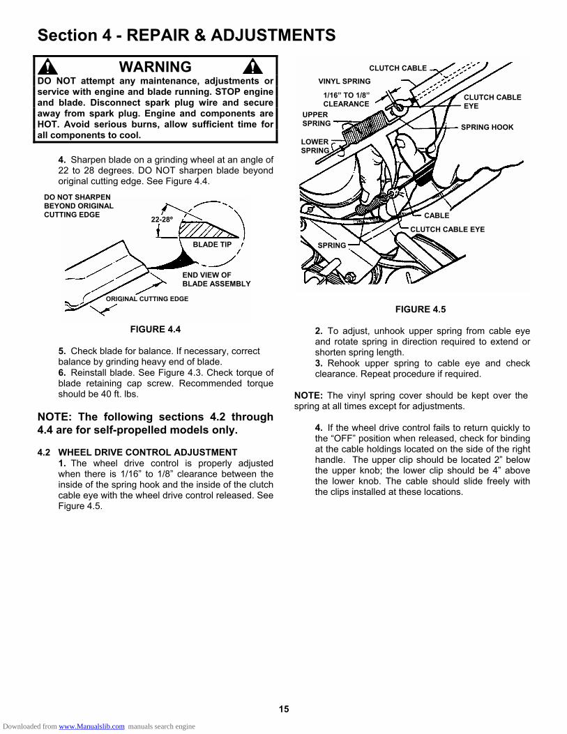
4. Sharpen blade on a grinding wheel at an angle of 22 to 28 degrees. DO NOT sharpen blade beyond original cutting edge. See Figure 4.4.
FIGURE 4.4
5. Check blade for balance. If necessary, correct balance by grinding heavy end of blade. 6. Reinstall blade. See Figure 4.3. Check torque of blade retaining cap screw. Recommended torque should be 40 ft. lbs.
NOTE: The following sections 4.2 through 4.4 are for self-propelled models only. 4.2 WHEEL DRIVE CONTROL ADJUSTMENT
1. The wheel drive control is properly adjusted when there is 1/16” to 1/8” clearance between the inside of the spring hook and the inside of the clutch cable eye with the wheel drive control released. See Figure 4.5.
FIGURE 4.5
2. To adjust, unhook upper spring from cable eye and rotate spring in direction required to extend or shorten spring length. 3. Rehook upper spring to cable eye and check clearance. Repeat procedure if required.
NOTE: The vinyl spring cover should be kept over the spring at all times except for adjustments.
4. If the wheel drive control fails to return quickly to the “OFF” position when released, check for binding at the cable holdings located on the side of the right handle. The upper clip should be located 2” below the upper knob; the lower clip should be 4” above the lower knob. The cable should slide freely with the clips installed at these locations.
CLUTCH CABLE
VINYL SPRING
1/16” TO 1/8” CLEARANCE
UPPER SPRING
LOWER SPRING
CLUTCH CABLE EYE
SPRING HOOK
CABLE
CLUTCH CABLE EYE
SPRING
DO NOT SHARPEN BEYOND ORIGINAL CUTTING EDGE 22-28º
BLADE TIP
END VIEW OF BLADE ASSEMBLY
ORIGINAL CUTTING EDGE
Downloaded from www.Manualslib.com manuals search engine
16
Section 4 - REPAIR & ADJUSTMENTS
WARNING DO NOT attempt any maintenance, adjustments or service with engine and blade running. STOP engine and blade. Disconnect spark plug wire and secure away from spark plug. Engine and components are HOT. Avoid serious burns, allow sufficient time for all components to cool.
4.3 DRIVEN AND DRIVE DISC SERVICE
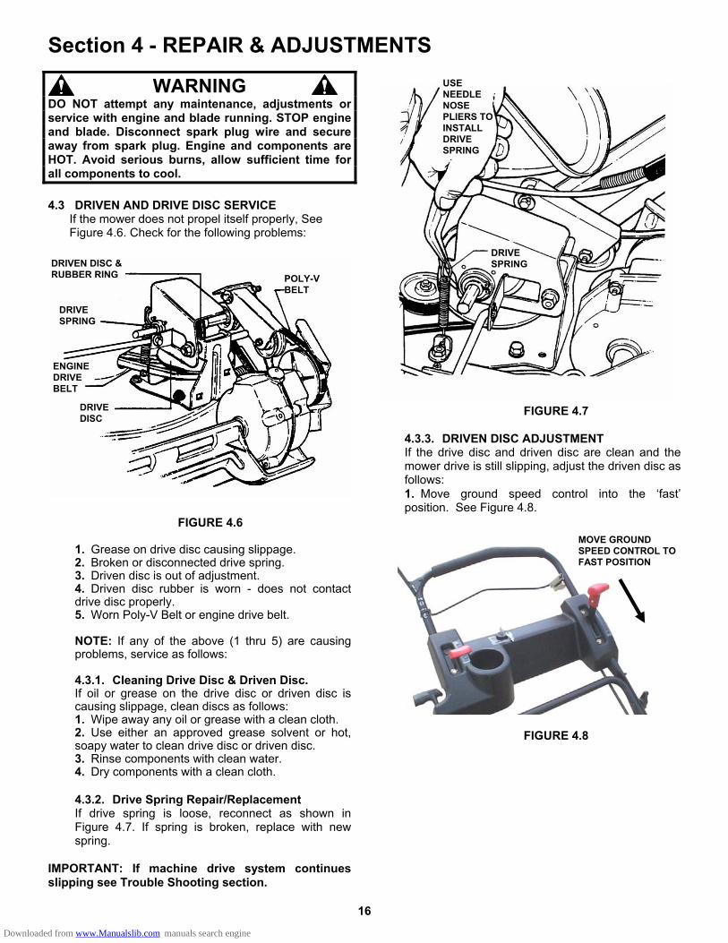
If the mower does not propel itself properly, See Figure 4.6. Check for the following problems:
FIGURE 4.6
1. Grease on drive disc causing slippage. 2. Broken or disconnected drive spring. 3. Driven disc is out of adjustment. 4. Driven disc rubber is worn - does not contact drive disc properly. 5. Worn Poly-V Belt or engine drive belt.
NOTE: If any of the above (1 thru 5) are causing problems, service as follows: 4.3.1. Cleaning Drive Disc & Driven Disc. If oil or grease on the drive disc or driven disc is causing slippage, clean discs as follows: 1. Wipe away any oil or grease with a clean cloth. 2. Use either an approved grease solvent or hot, soapy water to clean drive disc or driven disc. 3. Rinse components with clean water. 4. Dry components with a clean cloth.
4.3.2. Drive Spring Repair/Replacement If drive spring is loose, reconnect as shown in Figure 4.7. If spring is broken, replace with new spring.
IMPORTANT: If machine drive system continues slipping see Trouble Shooting section.
FIGURE 4.7
4.3.3. DRIVEN DISC ADJUSTMENT If the drive disc and driven disc are clean and the mower drive is still slipping, adjust the driven disc as follows: 1. Move ground speed control into the ‘fast’ position. See Figure 4.8.
FIGURE 4.8
USE NEEDLE NOSE PLIERS TO INSTALL DRIVE SPRING
DRIVE SPRING
MOVE GROUND SPEED CONTROL TO FAST POSITION
DRIVEN DISC & RUBBER RING POLY-V
BELT
DRIVE SPRING
ENGINE DRIVE BELT
DRIVE DISC
Downloaded from www.Manualslib.com manuals search engine
17
Section 4 - REPAIR & ADJUSTMENTS
WARNING DO NOT attempt any maintenance, adjustments or service with engine and blade running. STOP engine and blade. Disconnect spark plug wire and secure away from spark plug. Engine and components are HOT. Avoid serious burns, allow sufficient time for all components to cool.
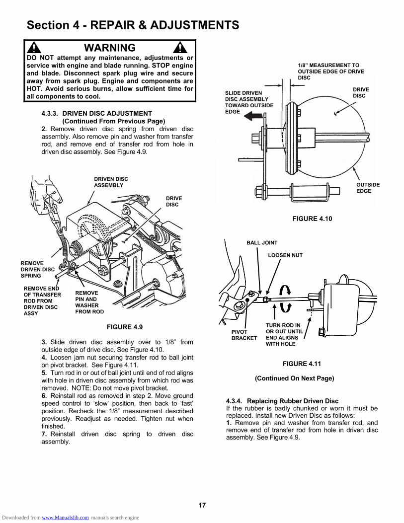
4.3.3. DRIVEN DISC ADJUSTMENT (Continued From Previous Page) 2. Remove driven disc spring from driven disc assembly. Also remove pin and washer from transfer rod, and remove end of transfer rod from hole in driven disc assembly. See Figure 4.9.
FIGURE 4.9 3. Slide driven disc assembly over to 1/8” from outside edge of drive disc. See Figure 4.10. 4. Loosen jam nut securing transfer rod to ball joint on pivot bracket. See Figure 4.11. 5. Turn rod in or out of ball joint until end of rod aligns with hole in driven disc assembly from which rod was removed. NOTE: Do not move pivot bracket. 6. Reinstall rod as removed in step 2. Move ground speed control to ‘slow’ position, then back to ‘fast’ position. Recheck the 1/8” measurement described previously. Readjust as needed. Tighten nut when finished. 7. Reinstall driven disc spring to driven disc assembly.
FIGURE 4.10
FIGURE 4.11
(Continued On Next Page)
4.3.4. Replacing Rubber Driven Disc If the rubber is badly chunked or worn it must be replaced. Install new Driven Disc as follows: 1. Remove pin and washer from transfer rod, and remove end of transfer rod from hole in driven disc assembly. See Figure 4.9.
DRIVEN DISC ASSEMBLY
DRIVE DISC
REMOVE DRIVEN DISC SPRING
REMOVE END OF TRANSFER ROD FROM DRIVEN DISC ASSY
BALL JOINT
TURN ROD IN OR OUT UNTIL END ALIGNS WITH HOLE
PIVOT BRACKET
1/8” MEASUREMENT TO OUTSIDE EDGE OF DRIVE DISC
DRIVE DISC SLIDE DRIVEN
DISC ASSEMBLY TOWARD OUTSIDE EDGE
OUTSIDE EDGE
REMOVE PIN AND WASHER FROM ROD
LOOSEN NUT
Downloaded from www.Manualslib.com manuals search engine
18
Section 4 - REPAIR & ADJUSTMENTS
WARNING DO NOT attempt any maintenance, adjustments or service with engine and blade running. STOP engine and blade. Disconnect spark plug wire and secure away from spark plug. Engine and components are HOT. Avoid serious burns, allow sufficient time for all components to cool.
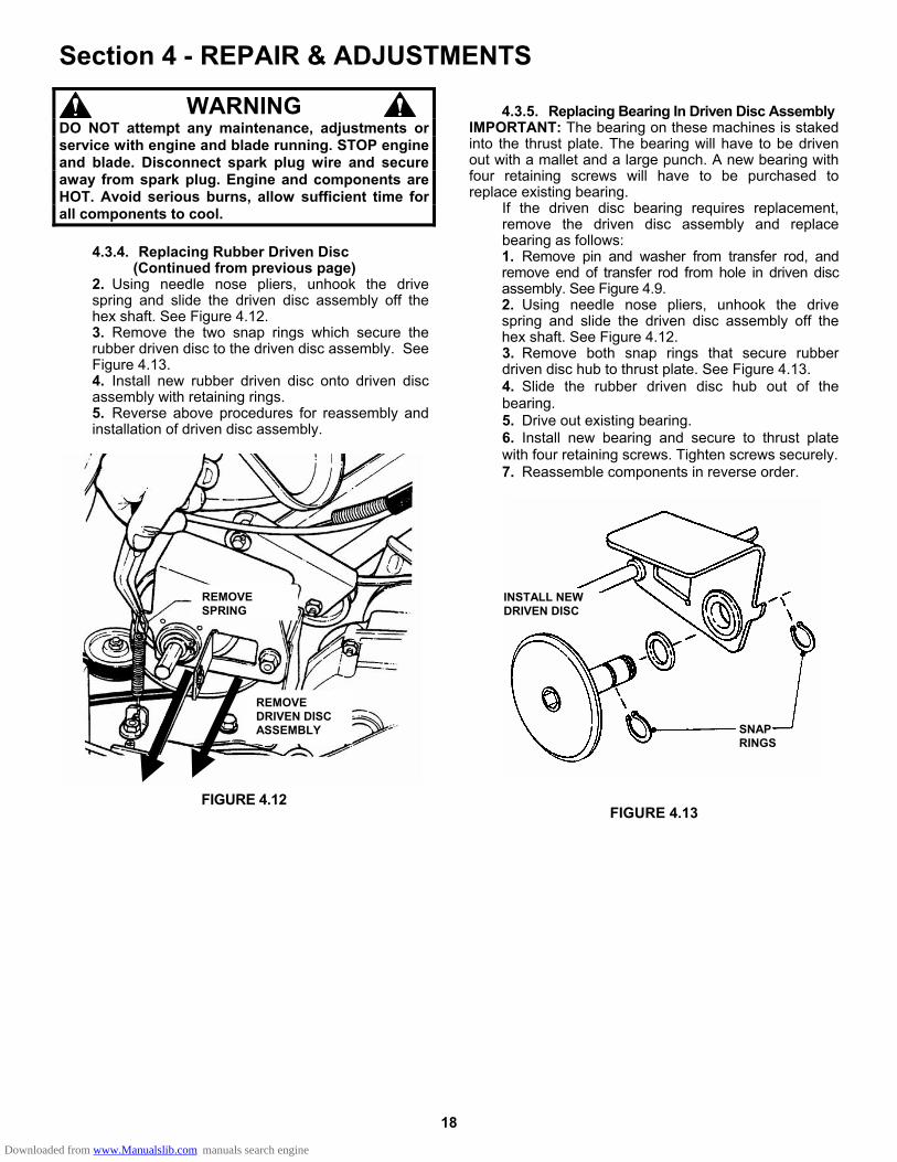
4.3.4. Replacing Rubber Driven Disc (Continued from previous page) 2. Using needle nose pliers, unhook the drive spring and slide the driven disc assembly off the hex shaft. See Figure 4.12. 3. Remove the two snap rings which secure the rubber driven disc to the driven disc assembly. See Figure 4.13. 4. Install new rubber driven disc onto driven disc assembly with retaining rings. 5. Reverse above procedures for reassembly and installation of driven disc assembly.
FIGURE 4.12
4.3.5. Replacing Bearing In Driven Disc Assembly
IMPORTANT: The bearing on these machines is staked into the thrust plate. The bearing will have to be driven out with a mallet and a large punch. A new bearing with four retaining screws will have to be purchased to replace existing bearing.
If the driven disc bearing requires replacement, remove the driven disc assembly and replace bearing as follows: 1. Remove pin and washer from transfer rod, and remove end of transfer rod from hole in driven disc assembly. See Figure 4.9. 2. Using needle nose pliers, unhook the drive spring and slide the driven disc assembly off the hex shaft. See Figure 4.12. 3. Remove both snap rings that secure rubber driven disc hub to thrust plate. See Figure 4.13. 4. Slide the rubber driven disc hub out of the bearing. 5. Drive out existing bearing. 6. Install new bearing and secure to thrust plate with four retaining screws. Tighten screws securely. 7. Reassemble components in reverse order.
FIGURE 4.13
REMOVE SPRING
INSTALL NEW DRIVEN DISC
SNAP RINGS
REMOVE DRIVEN DISC ASSEMBLY
Downloaded from www.Manualslib.com manuals search engine
19
Section 4 - REPAIR & ADJUSTMENTS
WARNING DO NOT attempt any maintenance, adjustments or service with engine and blade running. STOP engine and blade. Disconnect spark plug wire and secure away from spark plug. Engine and components are HOT. Avoid serious burns, allow sufficient time for all components to cool.
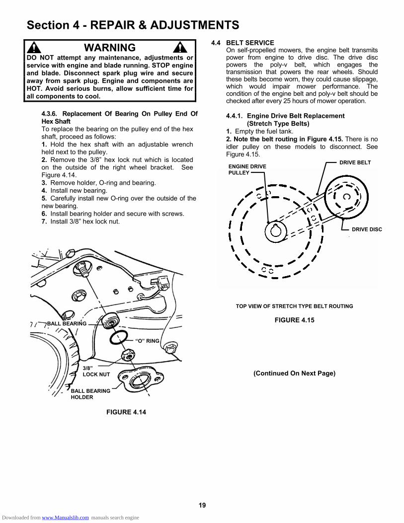
4.3.6. Replacement Of Bearing On Pulley End Of Hex Shaft To replace the bearing on the pulley end of the hex shaft, proceed as follows: 1. Hold the hex shaft with an adjustable wrench held next to the pulley. 2. Remove the 3/8” hex lock nut which is located on the outside of the right wheel bracket. See Figure 4.14. 3. Remove holder, O-ring and bearing. 4. Install new bearing. 5. Carefully install new O-ring over the outside of the new bearing. 6. Install bearing holder and secure with screws. 7. Install 3/8” hex lock nut.
FIGURE 4.14
4.4 BELT SERVICE On self-propelled mowers, the engine belt transmits power from engine to drive disc. The drive disc powers the poly-v belt, which engages the transmission that powers the rear wheels. Should these belts become worn, they could cause slippage, which would impair mower performance. The condition of the engine belt and poly-v belt should be checked after every 25 hours of mower operation. 4.4.1. Engine Drive Belt Replacement (Stretch Type Belts) 1. Empty the fuel tank. 2. Note the belt routing in Figure 4.15. There is no idler pulley on these models to disconnect. See Figure 4.15.
TOP VIEW OF STRETCH TYPE BELT ROUTING
FIGURE 4.15
(Continued On Next Page)
BALL BEARING
“O” RING
3/8” LOCK NUT
BALL BEARING HOLDER
DRIVE DISC
DRIVE BELT ENGINE DRIVE PULLEY
Downloaded from www.Manualslib.com manuals search engine
20
Section 4 - REPAIR & ADJUSTMENTS
WARNING DO NOT attempt any maintenance, adjustments or service with engine and blade running. STOP engine and blade. Disconnect spark plug wire and secure away from spark plug. Engine and components are HOT. Avoid serious burns, allow sufficient time for all components to cool.
4.4.1. Engine Drive Belt Replacement (Stretch Type Belts)
(Continued From Previous Page) IMPORTANT: Drain fuel tank before tipping mower. DO NOT tip machine with carburetor or spark plug down. Oil from crankcase will saturate the air filter and cause the engine to be hard to start or not start at all. If contamination does occur, the air filter will have to be replaced.
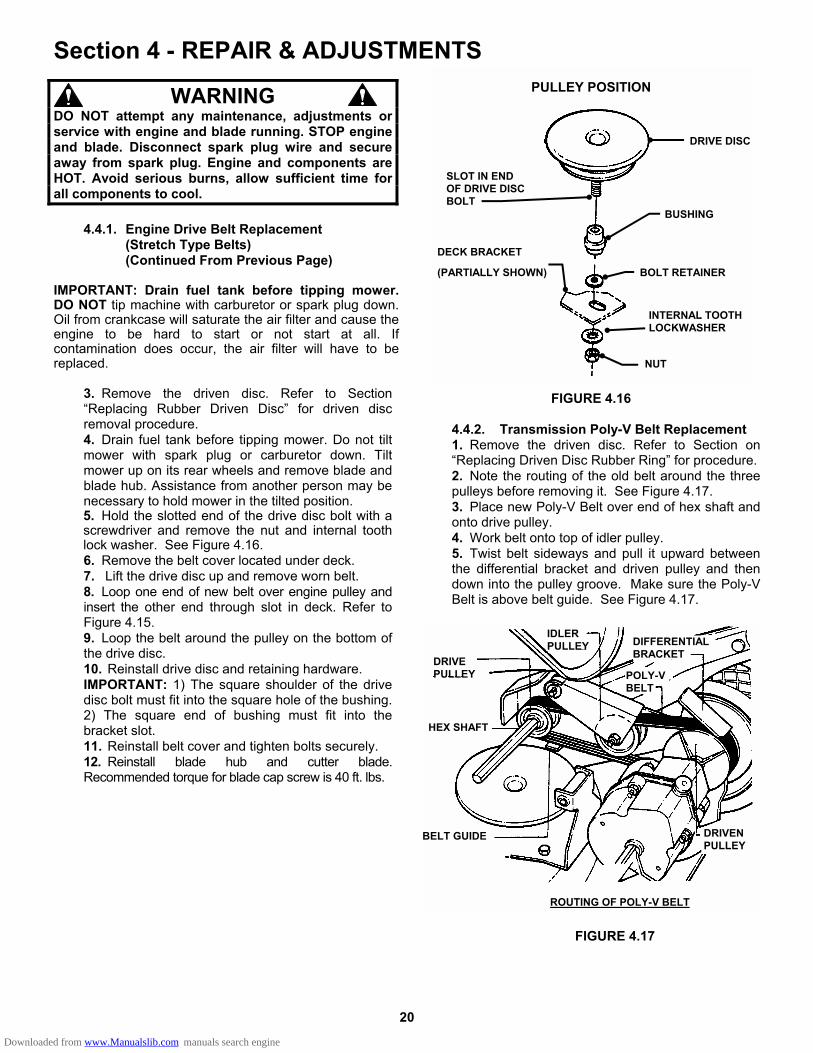
3. Remove the driven disc. Refer to Section “Replacing Rubber Driven Disc” for driven disc removal procedure. 4. Drain fuel tank before tipping mower. Do not tilt mower with spark plug or carburetor down. Tilt mower up on its rear wheels and remove blade and blade hub. Assistance from another person may be necessary to hold mower in the tilted position. 5. Hold the slotted end of the drive disc bolt with a screwdriver and remove the nut and internal tooth lock washer. See Figure 4.16. 6. Remove the belt cover located under deck. 7. Lift the drive disc up and remove worn belt. 8. Loop one end of new belt over engine pulley and insert the other end through slot in deck. Refer to Figure 4.15. 9. Loop the belt around the pulley on the bottom of the drive disc. 10. Reinstall drive disc and retaining hardware. IMPORTANT: 1) The square shoulder of the drive disc bolt must fit into the square hole of the bushing. 2) The square end of bushing must fit into the bracket slot. 11. Reinstall belt cover and tighten bolts securely. 12. Reinstall blade hub and cutter blade. Recommended torque for blade cap screw is 40 ft. lbs.
PULLEY POSITION
FIGURE 4.16
4.4.2. Transmission Poly-V Belt Replacement 1. Remove the driven disc. Refer to Section on “Replacing Driven Disc Rubber Ring” for procedure. 2. Note the routing of the old belt around the three pulleys before removing it. See Figure 4.17. 3. Place new Poly-V Belt over end of hex shaft and onto drive pulley. 4. Work belt onto top of idler pulley. 5. Twist belt sideways and pull it upward between the differential bracket and driven pulley and then down into the pulley groove. Make sure the Poly-V Belt is above belt guide. See Figure 4.17.
FIGURE 4.17
IDLER PULLEY
DRIVE PULLEY
DIFFERENTIAL BRACKET
POLY-V BELT
DRIVEN PULLEY
BELT GUIDE
HEX SHAFT
ROUTING OF POLY-V BELT
DRIVE DISC
SLOT IN END OF DRIVE DISC BOLT
BUSHING
BOLT RETAINER
DECK BRACKET
(PARTIALLY SHOWN)
INTERNAL TOOTH LOCKWASHER
NUT
Downloaded from www.Manualslib.com manuals search engine
21
Section 4 - REPAIR & ADJUSTMENTS 4.5. BATTERY SERVICE
4.5.1. NEW BATTERY PREPARATION 1. Remove battery from carton. 2. Place battery in a well ventilated area on a level non-concrete surface. 3. Remove battery cell caps. Fill cells as required with electrolyte (supplied with battery) to proper level. Filling battery with electrolyte will bring the battery to 80% charged state. 4. With cell caps removed, connect battery charger to battery terminals; RED to positive (+) and BLACK to negative (-) terminal.
IMPORTANT: Never place anything in battery other than specified electrolyte.
5. Slow charge the battery at 1 amp for 2 hours to bring the battery to full charge. 6. After charging, check level of electrolyte and add as needed to bring to proper fluid level. 7. Reinstall cell caps. 8. Install battery into power unit. 9. Connect positive (+) cable (red) first, from wiring harness to the positive terminal (+) on battery using bolt and nut provided in hardware bag. Connect negative (-) cable (black) last, to negative terminal (-) on battery using bolt and nut. Apply a small amount of grease over terminals to prevent corrosion.
WARNING DO NOT over fill battery with electrolyte. Shield the positive terminal with terminal cover located on battery harness. This prevents metal from touching the positive terminal, which could cause sparks. The electrolyte (acid) produces a highly explosive gas. Keep all sparks, flame and fire away from area when charging battery or when handling electrolyte or battery. Electrolyte (acid) is a highly corrosive liquid. Wear eye protection. Wash affected areas immediately after having eye or skin contact with electrolyte (acid). Battery acid is corrosive. Rinse empty acid containers with water and mutilate before discarding. If acid is spilled on battery, bench, or clothing, etc., Flush with clear water and neutralize with baking soda. Never attempt to charge battery while installed on the walk behind. Never use “BOOST” chargers on the battery.
4.5.2. BATTERY SERVICE 1. Remove battery. 2. Place battery in a well ventilated area on a level surface. 3. Using distilled water, refill cells as required to cover cell plates. 4. With cell caps removed, connect battery charger to battery terminals. Red to positive (+) terminal and black to negative (-) terminal. 5. Slow charge battery at 1 amp for 10 hours. 6. If battery will not accept charge or is partially charged after 10 hours of charging at 1 amp, replace with new battery.
4.5.3. BATTERY STORAGE If Walk Behind is to be stored out of season on its rear bumper, it is recommended the battery be removed, charged and stored. 1. Remove battery. 2. Perform battery service. 3. Bring battery to full charge, if required. 4. Store battery in an area away from the Walk Behind on a wood surface. DO NOT STORE BATTERY ON A CONCRETE SURFACE.
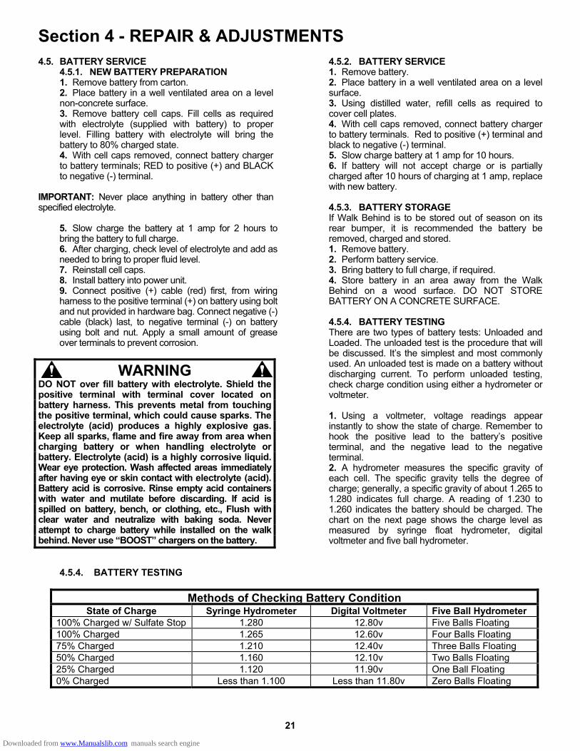
4.5.4. BATTERY TESTING There are two types of battery tests: Unloaded and Loaded. The unloaded test is the procedure that will be discussed. It’s the simplest and most commonly used. An unloaded test is made on a battery without discharging current. To perform unloaded testing, check charge condition using either a hydrometer or voltmeter. 1. Using a voltmeter, voltage readings appear instantly to show the state of charge. Remember to hook the positive lead to the battery’s positive terminal, and the negative lead to the negative terminal. 2. A hydrometer measures the specific gravity of each cell. The specific gravity tells the degree of charge; generally, a specific gravity of about 1.265 to 1.280 indicates full charge. A reading of 1.230 to 1.260 indicates the battery should be charged. The chart on the next page shows the charge level as measured by syringe float hydrometer, digital voltmeter and five ball hydrometer.
4.5.4. BATTERY TESTING
Methods of Checking Battery ConditionState of Charge Syringe Hydrometer Digital Voltmeter Five Ball Hydrometer
100% Charged w/ Sulfate Stop 1.280 12.80v Five Balls Floating 100% Charged 1.265 12.60v Four Balls Floating 75% Charged 1.210 12.40v Three Balls Floating 50% Charged 1.160 12.10v Two Balls Floating 25% Charged 1.120 11.90v One Ball Floating 0% Charged Less than 1.100 Less than 11.80v Zero Balls Floating
Downloaded from www.Manualslib.com manuals search engine

22
TROUBLESHOOTING
PROBLEM PROBABLE CAUSE CORRECTIVE ACTION Engine Will Not Start 1. Fuel tank empty. 1. Fill fuel tank with fresh fuel. Using Recoil Starter 2. Engine needs choking or priming. 2. Choke/Prime. Check Engine Manual for
Instructions. 3. Spark plug wire disconnected. 3. Place spark plug wire onto spark plug. 4. Kawasaki Engines Only – Fuel Shut-Off in the “OFF”
position 4. Turn Fuel Shut-Off to “ON” position
Engine Stalls or Stops After Running
1. Blade control is released or is not being held securely against handle.
1. Blade control should be held securely against handle at all times during operation of mower.
2. Fuel tank empty. 2. Fill with fuel to proper level. 3. Engine air pre-cleaner and or air cleaner dirty. 3. Clean free of all debris. 4. Spark plug defective or gap set improperly. 4. Service spark plug. 5. Water, debris or stale fuel in fuel system. 5. Drain and clean fuel system. 6. Kawasaki Engines Only – Fuel Shut-Off in the “OFF”
position 6. Turn Fuel Shut-Off to “ON” position
Engine Loses Power 1. Engine air pre-cleaner or air cleaner dirty 1. Clean or replace filters. 2. Spark plug faulty. 2. Service spark plug. 3. Water, debris or stale fuel in fuel system. 3. Drain and clean fuel system.
Excessive Vibration 1. Damaged, out of balance or bent mower blade. 1. Service mower blade. 2. Loose blade components. 2. Service and tighten loose parts. 3. Loose or missing air lift (if equipped). 3. Replace air lifts. Tighten to proper torque. 4. Lumpy or frayed belt 4. Replace belt.
Mower Will Not Move 1. Damaged transmission 1. Contact authorized SNAPPER dealer.Loss Of Traction 2. Traction drive belt requires replacement 2. Replace traction drive belt.
(Self-Propelled Models) 3. Driven disc slipping 3. Clean or replace driven disc. Cutting Grass 1. Cutting height too low or high. 1. Adjust cutting height.
Improperly 2. Engine speed too slow. 2. Move engine speed control to “FAST” position. 3. Forward ground speed too fast. 3. Move ground speed control to a slower speed. 4. Terraced cut, side to side. 4. Adjust height of cut with height adjust levers. 5. Excessive deck pitch, front to rear. 5. Adjust height of cut with height adjust levers. 6. Cutting blade dull or damaged. 6. Sharpen cutting edges or replace blade.
Poor Grass Discharge 1. Engine speed too slow. 1. Move engine speed control to “FAST” position. 2. Forward speed too fast. 2. Move ground speed control to a slower speed. 3. Grass is wet. 3. Mow when grass is dry. 4. Excessively worn or damaged blade. 4. Service mower blade. 5. Build up of grass clippings and debris under deck. 5. Clean deck. 6. Improper blade installed on deck. 6. Install proper SNAPPER blade. 7. Blade installed improperly on deck. 7. Install blade properly.
Oil Leaking 1. Leaking engine case. 1. Contact authorized SNAPPER dealer. 2. Check and tighten drain plug. 3. Make sure dip stick or oil filler cap is securely
in place.
Downloaded from www.Manualslib.com manuals search engine
23
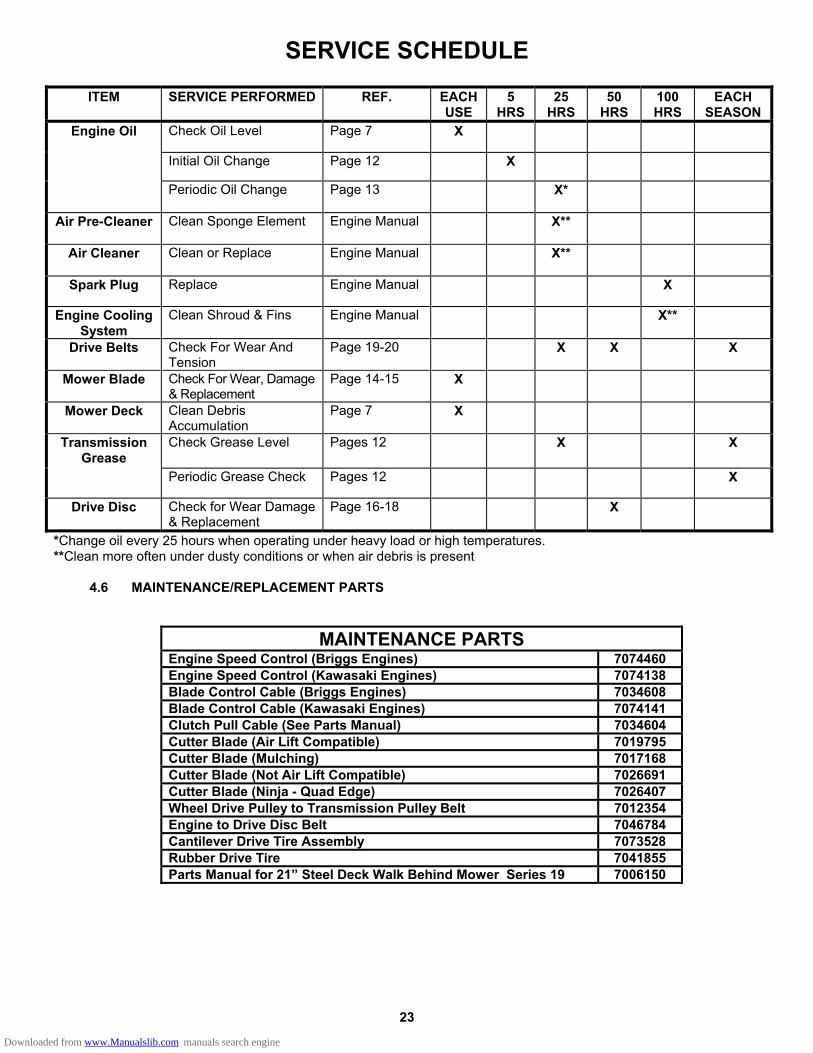
SERVICE SCHEDULE
ITEM SERVICE PERFORMED REF. EACH USE
5 HRS
25 HRS
50 HRS
100 HRS
EACH SEASON
Engine Oil Check Oil Level Page 7 X
Initial Oil Change Page 12 X
Periodic Oil Change Page 13 X*
Air Pre-Cleaner Clean Sponge Element Engine Manual
X**
Air Cleaner Clean or Replace Engine Manual
X**
Spark Plug Replace Engine Manual X
Engine Cooling System
Clean Shroud & Fins Engine Manual X**
Drive Belts Check For Wear And Tension
Page 19-20 X X X
Mower Blade Check For Wear, Damage & Replacement
Page 14-15 X
Mower Deck Clean Debris Accumulation
Page 7 X
Transmission Grease
Check Grease Level Pages 12 X X
Periodic Grease Check Pages 12 X
Drive Disc Check for Wear Damage & Replacement
Page 16-18 X
*Change oil every 25 hours when operating under heavy load or high temperatures. **Clean more often under dusty conditions or when air debris is present
4.6 MAINTENANCE/REPLACEMENT PARTS
MAINTENANCE PARTS Engine Speed Control (Briggs Engines) 7074460 Engine Speed Control (Kawasaki Engines) 7074138 Blade Control Cable (Briggs Engines) 7034608 Blade Control Cable (Kawasaki Engines) 7074141 Clutch Pull Cable (See Parts Manual) 7034604 Cutter Blade (Air Lift Compatible) 7019795 Cutter Blade (Mulching) 7017168 Cutter Blade (Not Air Lift Compatible) 7026691 Cutter Blade (Ninja - Quad Edge) 7026407 Wheel Drive Pulley to Transmission Pulley Belt 7012354 Engine to Drive Disc Belt 7046784 Cantilever Drive Tire Assembly 7073528 Rubber Drive Tire 7041855 Parts Manual for 21” Steel Deck Walk Behind Mower Series 19 7006150
Downloaded from www.Manualslib.com manuals search engine

24
2 YEAR LIMITED WARRANTY
For two (2) years from purchase date for the original purchaser's residential, non-commercial use, SNAPPER, through any authorized SNAPPER dealer will replace, free of charge (except for taxes where applicable), any part or parts found upon examination by the factory at McDonough, Georgia, to be defective in material or workmanship or both. For ninety (90) days from purchase date for the original purchaser's commercial, rental, or other non-residential use, SNAPPER, through any authorized SNAPPER dealer will replace, free of charge, any part or parts found upon examination by the factory at McDonough, Georgia, to be defective in material or workmanship or both. All transportation costs incurred by the purchaser in submitting material to an authorized SNAPPER dealer for replacement under this warranty must be paid by the purchaser. This warranty does not apply to certain transmissions, to engines and their components, and batteries, as these items are warranted separately. This warranty does not apply to parts that have been damaged by accident, alteration, abuse, improper lubrication, normal wear, or other cause beyond the control of SNAPPER. This warranty does not cover any machine or component part that has been altered or modified changing safety, performance, or durability. Batteries have a one (1) year warranty period with free replacement if required for one (1) year from the original purchase date. SNAPPER will not be responsible for any installation cost incurred. The battery warranty only covers original equipment batteries and does not cover damage to the battery or machine caused by neglect or abuse, destruction by fire, explosion, freezing, overcharging, improper maintenance, or use of improper electrolyte. There is no other express warranty.
DISCLAIMER OF WARRANTY Implied warranties, including those of merchantability and fitness for a particular purpose, are limited to two (2) years from purchase date for the original purchaser's residential or other non-commercial use, and ninety (90) days from purchase for the original purchaser's commercial, rental or other non-residential use, and to the extent permitted by law, any and all implied warranties are excluded. This is the exclusive remedy. Liabilities for consequential damages, under any and all warranties are excluded. Some states do not allow limitations on how long an implied warranty lasts, or do not allow the exclusion or limitation of incidental or consequential damages, so the above limitation or exclusion may not apply to you. This warranty gives you specific legal rights, and you may also have other rights which vary from state to state. WARNING: THE USE OF REPLACEMENT PARTS OTHER THAN GENUINE SNAPPER PARTS MAY IMPAIR THE SAFETY OF SNAPPER PRODUCTS AND WILL VOID ANY LIABILITY AND WARRANTY BY SNAPPER ASSOCIATED WITH THE USE OF SUCH PARTS. IMPORTANT: Please fill out the attached SNAPPER Product Registration Card immediately and mail to: Snapper’s Product Registration Center, P.O. Box 1379, McDonough, Georgia 30253
Downloaded from www.Manualslib.com manuals search engine

25
PRIMARY MAINTENANCE
Downloaded from www.Manualslib.com manuals search engine

26
PRIMARY MAINTENANCE
Downloaded from www.Manualslib.com manuals search engine
27
PRIMARY MAINTENANCE
Downloaded from www.Manualslib.com manuals search engine
28
PRIMARY MAINTENANCE
Downloaded from www.Manualslib.com manuals search engine

29
SNAPPER PRODUCT REGISTRATION FORM
IMPORTANT: KEEP THIS INFORMATION FOR YOUR PERSONAL RECORDS (Complete the following information on your Snapper purchase)
Model Number_____________________________________________________________
Serial Number _____________________________________________________________
Date of Purchase ___________________________________________________________
Retailer____________________________________________________________________
Retailer’s Phone Number ____________________________________________________
It is very important that you register your purchase with Snapper to ensure warranty coverage. Please mail your product registration card to:
Snapper at P.O. Box 777, McDonough, Georgia 30253.
Or you may register on line at www.snapper.com.
You can contact us at our web site or if you would like to speak with a Customer Service Representative. Call us at the Snapper Customer Relations Center. For faster service please have your Serial Number and Model Number available.
Call the Snapper Customer Relations Center at 1-800-935-2967.
Downloaded from www.Manualslib.com manuals search engine

30
NOTES ___________________________________________________________________ ___________________________________________________________________ ___________________________________________________________________ ___________________________________________________________________ ___________________________________________________________________ ___________________________________________________________________ ___________________________________________________________________ ___________________________________________________________________ ___________________________________________________________________ ___________________________________________________________________ ___________________________________________________________________ ___________________________________________________________________ ___________________________________________________________________ ___________________________________________________________________ ___________________________________________________________________ ___________________________________________________________________ ___________________________________________________________________ ___________________________________________________________________ ___________________________________________________________________ ___________________________________________________________________ ___________________________________________________________________ ___________________________________________________________________ ___________________________________________________________________ ___________________________________________________________________ ___________________________________________________________________ ___________________________________________________________________ ___________________________________________________________________ ___________________________________________________________________ ___________________________________________________________________ ___________________________________________________________________ ___________________________________________________________________ ___________________________________________________________________ ___________________________________________________________________ ___________________________________________________________________ ___________________________________________________________________ ___________________________________________________________________ ___________________________________________________________________ ___________________________________________________________________ ___________________________________________________________________ ___________________________________________________________________ ___________________________________________________________________ ___________________________________________________________________
Downloaded from www.Manualslib.com manuals search engine

31
NOTES ___________________________________________________________________ ___________________________________________________________________ ___________________________________________________________________ ___________________________________________________________________ ___________________________________________________________________ ___________________________________________________________________ ___________________________________________________________________ ___________________________________________________________________ ___________________________________________________________________ ___________________________________________________________________ ___________________________________________________________________ ___________________________________________________________________ ___________________________________________________________________ ___________________________________________________________________ ___________________________________________________________________ ___________________________________________________________________ ___________________________________________________________________ ___________________________________________________________________ ___________________________________________________________________ ___________________________________________________________________ ___________________________________________________________________ ___________________________________________________________________ ___________________________________________________________________ ___________________________________________________________________ ___________________________________________________________________ ___________________________________________________________________ ___________________________________________________________________ ___________________________________________________________________ ___________________________________________________________________ ___________________________________________________________________ ___________________________________________________________________ ___________________________________________________________________ ___________________________________________________________________ ___________________________________________________________________ ___________________________________________________________________ ___________________________________________________________________ ___________________________________________________________________ ___________________________________________________________________ ___________________________________________________________________ ___________________________________________________________________ ___________________________________________________________________ ___________________________________________________________________
Downloaded from www.Manualslib.com manuals search engine

32
Safety Instructions & Operator’s Manual for
21” STEEL DECK WALK BEHIND MOWERS SERIES 19
IMPORTANT Snapper products are built using engines that meet or exceed all applicable emissions requirements on the date manufactured. The labels on those engines contain very important emissions information and critical safety warnings. Read, Understand, and Follow all warnings and instructions in this manual, the engine manual, and on the machine, engine and attachments. If you have any questions about your Snapper product, contact your local authorized Snapper dealer or contact Snapper Customer Service at Snapper, McDonough, GA. 30253. Phone: (1-800-935-2967). COPYRIGHT © 2005 SNAPPER – A DIVISION OF SIMPLICITY MFG., INC. ALL RIGHTS RESERVED
MANUAL No. 7100366 (I.R. 9/13/2005)
TP 100-5084-IR-WB-N
WARNING ENGINE EXHAUST, SOME OF ITS CONSTITUENTS, AND CERTAIN VEHICLE COMPONENTS CONTAIN OR EMIT CHEMICALS KNOWN TO THE STATE OF CALIFORNIA TO CAUSE CANCER OR OTHER REPRODUCTIVE HARM.
WARNING BATTERY POSTS, TERMINALS AND RELATED ACCESSORIES CONTAIN LEAD AND LEAD COMPOUNDS, CHEMICALS KNOWN TO THE STATE OF CALIFORNIA TO CAUSE CANCER AND BIRTH DEFECTS OR OTHER REPRODUCTIVE HARM. WASH HANDS AFTER HANDLING.
Downloaded from www.Manualslib.com manuals search engine