SNAP ETHERNET-BASED I/O UNITS USER’S GUIDE · SNAP ETHERNET-BASED I/O UNITS USER’S GUIDE SNAP...
142
SNAP ETHERNET-BASED I/O UNITS USER’S GUIDE SNAP Simple I/O™ SNAP Ethernet I/O™ SNAP Ultimate I/O™ Form 1460-060629—June 2006 43044 Business Park Drive • Temecula • CA 92590-3614 Phone: 800-321-OPTO (6786) or 951-695-3000 Fax: 800-832-OPTO (6786) or 951-695-2712 www.opto22.com Product Support Services 800-TEK-OPTO (835-6786) or 951-695-3080 Fax: 951-695-3017 Email: [email protected] Web: support.opto22.com
Transcript of SNAP ETHERNET-BASED I/O UNITS USER’S GUIDE · SNAP ETHERNET-BASED I/O UNITS USER’S GUIDE SNAP...

SNAP ETHERNET-BASED I/O UNITS USER’S GUIDE
SNAP Simple I/O™SNAP Ethernet I/O™SNAP Ultimate I/O™
Form 1460-060629—June 2006
43044 Business Park Drive • Temecula • CA 92590-3614Phone: 800-321-OPTO (6786) or 951-695-3000
Fax: 800-832-OPTO (6786) or 951-695-2712www.opto22.com
Product Support Services800-TEK-OPTO (835-6786) or 951-695-3080
Fax: 951-695-3017Email: [email protected]
Web: support.opto22.com

SNAP Ethernet-Based I/O Units User’s Guideii
SNAP Ethernet-Based I/O Units User’s GuideForm 1460-060629—June 2006
Copyright © 2003–2006 Opto 22.All rights reserved.Printed in the United States of America.
The information in this manual has been checked carefully and is believed to be accurate; however, Opto 22 assumes no responsibility for possible inaccuracies or omissions. Specifications are subject to change without notice.
Opto 22 warrants all of its products to be free from defects in material or workmanship for 30 months from the manufacturing date code. This warranty is limited to the original cost of the unit only and does not cover installation, labor, or any other contingent costs. Opto 22 I/O modules and solid-state relays with date codes of 1/96 or later are guaranteed for life. This lifetime warranty excludes reed relay, SNAP serial communication modules, SNAP PID modules, and modules that contain mechanical contacts or switches. Opto 22 does not warrant any product, components, or parts not manufactured by Opto 22; for these items, the warranty from the original manufacturer applies. These products include, but are not limited to, OptoTerminal-G70, OptoTerminal-G75, and Sony Ericsson GT-48; see the product data sheet for specific warranty information. Refer to Opto 22 form number 1042 for complete warranty information.
Cyrano, Opto 22 FactoryFloor, Optomux, and Pamux are registered trademarks of Opto 22. Generation 4, ioControl, ioDisplay, ioManager, ioProject, ioUtilities, mistic, Nvio, Nvio.net Web Portal, OptoConnect, OptoControl, OptoDisplay, OptoENETSniff, OptoOPCServer, OptoScript, OptoServer, OptoTerminal, OptoUtilities, SNAP Ethernet I/O, SNAP I/O, SNAP OEM I/O, SNAP PAC, SNAP Simple I/O, SNAP Ultimate I/O, and SNAP Wireless LAN I/O are trademarks of Opto 22.
ActiveX, JScript, Microsoft, MS-DOS, VBScript, Visual Basic, Visual C++, and Windows are either registered trademarks or trademarks of Microsoft Corporation in the United States and other countries. Linux is a registered trademark of Linus Torvalds. Unicenter is a registered trademark of Computer Associates International, Inc. ARCNET is a registered trademark of Datapoint Corporation. Modbus is a registered trademark of Schneider Electric. Wiegand is a registered trademark of Sensor Engineering Corporation. Nokia, Nokia M2M Platform, Nokia M2M Gateway Software, and Nokia 31 GSM Connectivity Terminal are trademarks or registered trademarks of Nokia Corporation. Sony is a trademark of Sony Corporation. Ericsson is a trademark of Telefonaktiebolaget LM Ericsson.
All other brand or product names are trademarks or registered trademarks of their respective companies or organizations.

SNAP Ethernet-Based I/O Units User’s Guide iiiiii
Table of Contents
Chapter 1: Introduction . . . . . . . . . . . . . . . . . . . . . . . . . . . . . . . . . . . . . . . . . . . . . . . . . . 1
Welcome to SNAP Ethernet-Based I/O. . . . . . . . . . . . . . . . . . . . . . . . . . . . . . . . . . . . . . . . . . . . . . . . . . . . . . . . . 1
Hardware . . . . . . . . . . . . . . . . . . . . . . . . . . . . . . . . . . . . . . . . . . . . . . . . . . . . . . . . . . . . . . . . . . . . . . . . . . . . . 1
Software . . . . . . . . . . . . . . . . . . . . . . . . . . . . . . . . . . . . . . . . . . . . . . . . . . . . . . . . . . . . . . . . . . . . . . . . . . . . . . 2
About this Guide. . . . . . . . . . . . . . . . . . . . . . . . . . . . . . . . . . . . . . . . . . . . . . . . . . . . . . . . . . . . . . . . . . . . . . . . . . . . 3
Information Key . . . . . . . . . . . . . . . . . . . . . . . . . . . . . . . . . . . . . . . . . . . . . . . . . . . . . . . . . . . . . . . . . . . . . . . . 4
Other Documents You May Need . . . . . . . . . . . . . . . . . . . . . . . . . . . . . . . . . . . . . . . . . . . . . . . . . . . . . . . . . 4
For Help . . . . . . . . . . . . . . . . . . . . . . . . . . . . . . . . . . . . . . . . . . . . . . . . . . . . . . . . . . . . . . . . . . . . . . . . . . . . . . . . . . . 5
Chapter 2: Installing a SNAP Ethernet-Based I/O Unit . . . . . . . . . . . . . . . . . . . . . . 7
What You Will Need. . . . . . . . . . . . . . . . . . . . . . . . . . . . . . . . . . . . . . . . . . . . . . . . . . . . . . . . . . . . . . . . . . . . . . . . . 7
Installing Software . . . . . . . . . . . . . . . . . . . . . . . . . . . . . . . . . . . . . . . . . . . . . . . . . . . . . . . . . . . . . . . . . . . . . . . . . . 7
Installing Hardware . . . . . . . . . . . . . . . . . . . . . . . . . . . . . . . . . . . . . . . . . . . . . . . . . . . . . . . . . . . . . . . . . . . . . . . . . 8
Installing Modules on the Rack . . . . . . . . . . . . . . . . . . . . . . . . . . . . . . . . . . . . . . . . . . . . . . . . . . . . . . . . . . . 8
Removing a Module . . . . . . . . . . . . . . . . . . . . . . . . . . . . . . . . . . . . . . . . . . . . . . . . . . . . . . . . . . . . . . . . . . . . 9
Installing the Brain or Controller . . . . . . . . . . . . . . . . . . . . . . . . . . . . . . . . . . . . . . . . . . . . . . . . . . . . . . . . . 10
What’s Next? . . . . . . . . . . . . . . . . . . . . . . . . . . . . . . . . . . . . . . . . . . . . . . . . . . . . . . . . . . . . . . . . . . . . . . . . . . . . . 11
Configuring I/O . . . . . . . . . . . . . . . . . . . . . . . . . . . . . . . . . . . . . . . . . . . . . . . . . . . . . . . . . . . . . . . . . . . . . . . 11
Using PPP Over a Modem . . . . . . . . . . . . . . . . . . . . . . . . . . . . . . . . . . . . . . . . . . . . . . . . . . . . . . . . . . . . . . . . . . 12
Configuring PPP on the I/O Unit . . . . . . . . . . . . . . . . . . . . . . . . . . . . . . . . . . . . . . . . . . . . . . . . . . . . . . . . . 13
Attaching the Modem to the SNAP Ethernet-Based I/O Unit . . . . . . . . . . . . . . . . . . . . . . . . . . . . . . . . 17
Configuring Microsoft Windows Dial-up Networking on Windows 2000 . . . . . . . . . . . . . . . . . . . . . 17
Chapter 3: System Architecture . . . . . . . . . . . . . . . . . . . . . . . . . . . . . . . . . . . . . . . . .21
Communication Options . . . . . . . . . . . . . . . . . . . . . . . . . . . . . . . . . . . . . . . . . . . . . . . . . . . . . . . . . . . . . . . . . . . 21
Simultaneous Communication . . . . . . . . . . . . . . . . . . . . . . . . . . . . . . . . . . . . . . . . . . . . . . . . . . . . . . . . . . 22
SNAP Ethernet-Based I/O Units User’s Guideiv
Accessing SNAP Ethernet Systems I/O Units Over the Internet . . . . . . . . . . . . . . . . . . . . . . . . . . . . . . .23
Choosing Communication Methods . . . . . . . . . . . . . . . . . . . . . . . . . . . . . . . . . . . . . . . . . . . . . . . . . . . . . .23
System Architecture—SNAP Simple I/O . . . . . . . . . . . . . . . . . . . . . . . . . . . . . . . . . . . . . . . . . . . . . . . . . . . . . 24
System Architecture—SNAP Ethernet I/O. . . . . . . . . . . . . . . . . . . . . . . . . . . . . . . . . . . . . . . . . . . . . . . . . . . . 26
System Architecture—SNAP Ultimate I/O. . . . . . . . . . . . . . . . . . . . . . . . . . . . . . . . . . . . . . . . . . . . . . . . . . . . 26
Understanding the SNAP Ultimate Brain . . . . . . . . . . . . . . . . . . . . . . . . . . . . . . . . . . . . . . . . . . . . . . . . . .26The I/O Side of the Brain . . . . . . . . . . . . . . . . . . . . . . . . . . . . . . . . . . . . . . . . . . . . . . . . . . . . . . . . . . . .27The Control Side of the Brain . . . . . . . . . . . . . . . . . . . . . . . . . . . . . . . . . . . . . . . . . . . . . . . . . . . . . . . .27
Controlling the System . . . . . . . . . . . . . . . . . . . . . . . . . . . . . . . . . . . . . . . . . . . . . . . . . . . . . . . . . . . . . . . . .27
Communicating Peer-to-Peer on the Network . . . . . . . . . . . . . . . . . . . . . . . . . . . . . . . . . . . . . . . . . . . . .29
Communicating with Enterprise Systems and Third-Party Software . . . . . . . . . . . . . . . . . . . . . . . . . .30
The Complete System . . . . . . . . . . . . . . . . . . . . . . . . . . . . . . . . . . . . . . . . . . . . . . . . . . . . . . . . . . . . . . . . . .31
Networking. . . . . . . . . . . . . . . . . . . . . . . . . . . . . . . . . . . . . . . . . . . . . . . . . . . . . . . . . . . . . . . . . . . . . . . . . . . . . . . 32
Connecting the I/O Unit Directly to a PC or Controller . . . . . . . . . . . . . . . . . . . . . . . . . . . . . . . . . . . . . . .32Crossover Cables . . . . . . . . . . . . . . . . . . . . . . . . . . . . . . . . . . . . . . . . . . . . . . . . . . . . . . . . . . . . . . . . . .32
Attaching the I/O Unit to an Existing Ethernet Network . . . . . . . . . . . . . . . . . . . . . . . . . . . . . . . . . . . . .33
Using the I/O Unit in an Independent Network . . . . . . . . . . . . . . . . . . . . . . . . . . . . . . . . . . . . . . . . . . . .34
Communicating with the System via Modem . . . . . . . . . . . . . . . . . . . . . . . . . . . . . . . . . . . . . . . . . . . . .34
Specifications . . . . . . . . . . . . . . . . . . . . . . . . . . . . . . . . . . . . . . . . . . . . . . . . . . . . . . . . . . . . . . . . . . . . . . . . . . . . . 35
Specifications for SNAP Ethernet-Based Brains . . . . . . . . . . . . . . . . . . . . . . . . . . . . . . . . . . . . . . . . . . . . .35
LED Descriptions . . . . . . . . . . . . . . . . . . . . . . . . . . . . . . . . . . . . . . . . . . . . . . . . . . . . . . . . . . . . . . . . . . . . . . .35All Brains Except SNAP-ENET-S64 . . . . . . . . . . . . . . . . . . . . . . . . . . . . . . . . . . . . . . . . . . . . . . . . . . .35SNAP-ENET-S64 Brains . . . . . . . . . . . . . . . . . . . . . . . . . . . . . . . . . . . . . . . . . . . . . . . . . . . . . . . . . . . . .36
Feature Comparisons . . . . . . . . . . . . . . . . . . . . . . . . . . . . . . . . . . . . . . . . . . . . . . . . . . . . . . . . . . . . . . . . . . . . . . 36
SNAP Ethernet-Based Brain Comparison Chart . . . . . . . . . . . . . . . . . . . . . . . . . . . . . . . . . . . . . . . . . . . . .37
Additional Information on Features . . . . . . . . . . . . . . . . . . . . . . . . . . . . . . . . . . . . . . . . . . . . . . . . . . . . . .39Digital Point Features . . . . . . . . . . . . . . . . . . . . . . . . . . . . . . . . . . . . . . . . . . . . . . . . . . . . . . . . . . . . . .39Analog Point Features . . . . . . . . . . . . . . . . . . . . . . . . . . . . . . . . . . . . . . . . . . . . . . . . . . . . . . . . . . . . . .39Serial Communication . . . . . . . . . . . . . . . . . . . . . . . . . . . . . . . . . . . . . . . . . . . . . . . . . . . . . . . . . . . . .40PID Loops . . . . . . . . . . . . . . . . . . . . . . . . . . . . . . . . . . . . . . . . . . . . . . . . . . . . . . . . . . . . . . . . . . . . . . . .41Events, Timers, Event Messages, Email, Data Logging, Data Mirroring,
and Memory Map Copying . . . . . . . . . . . . . . . . . . . . . . . . . . . . . . . . . . . . . . . . . . . . . . . . . . . . .41UDP Streaming . . . . . . . . . . . . . . . . . . . . . . . . . . . . . . . . . . . . . . . . . . . . . . . . . . . . . . . . . . . . . . . . . . . .42Security . . . . . . . . . . . . . . . . . . . . . . . . . . . . . . . . . . . . . . . . . . . . . . . . . . . . . . . . . . . . . . . . . . . . . . . . . .42Scratch Pad Areas . . . . . . . . . . . . . . . . . . . . . . . . . . . . . . . . . . . . . . . . . . . . . . . . . . . . . . . . . . . . . . . . .42SNMP . . . . . . . . . . . . . . . . . . . . . . . . . . . . . . . . . . . . . . . . . . . . . . . . . . . . . . . . . . . . . . . . . . . . . . . . . . . .42PPP . . . . . . . . . . . . . . . . . . . . . . . . . . . . . . . . . . . . . . . . . . . . . . . . . . . . . . . . . . . . . . . . . . . . . . . . . . . . . .42FTP Server/Client . . . . . . . . . . . . . . . . . . . . . . . . . . . . . . . . . . . . . . . . . . . . . . . . . . . . . . . . . . . . . . . . . .42

:
SNAP Ethernet-Based I/O Units User’s Guide vv
Chapter 4: Maintaining the Ethernet-Based I/O Unit . . . . . . . . . . . . . . . . . . . . . .43
Introduction. . . . . . . . . . . . . . . . . . . . . . . . . . . . . . . . . . . . . . . . . . . . . . . . . . . . . . . . . . . . . . . . . . . . . . . . . . . . . . 43
Backup Battery . . . . . . . . . . . . . . . . . . . . . . . . . . . . . . . . . . . . . . . . . . . . . . . . . . . . . . . . . . . . . . . . . . . . . . . . 43
Changing or Viewing the IP Address . . . . . . . . . . . . . . . . . . . . . . . . . . . . . . . . . . . . . . . . . . . . . . . . . . . . . . . . 43
Changing the IP Address . . . . . . . . . . . . . . . . . . . . . . . . . . . . . . . . . . . . . . . . . . . . . . . . . . . . . . . . . . . . . . . 44Brains with Firmware Version 5.0 or Newer . . . . . . . . . . . . . . . . . . . . . . . . . . . . . . . . . . . . . . . . . . 44Brains with Older Firmware . . . . . . . . . . . . . . . . . . . . . . . . . . . . . . . . . . . . . . . . . . . . . . . . . . . . . . . . 45
Viewing the IP Address . . . . . . . . . . . . . . . . . . . . . . . . . . . . . . . . . . . . . . . . . . . . . . . . . . . . . . . . . . . . . . . . . 48
Resetting a Brain to Factory Defaults . . . . . . . . . . . . . . . . . . . . . . . . . . . . . . . . . . . . . . . . . . . . . . . . . . . . . . . . 50
Loading New Firmware . . . . . . . . . . . . . . . . . . . . . . . . . . . . . . . . . . . . . . . . . . . . . . . . . . . . . . . . . . . . . . . . . . . . 51
Loading SNAP Ultimate Brain Firmware . . . . . . . . . . . . . . . . . . . . . . . . . . . . . . . . . . . . . . . . . . . . . . . . . . 52
Loading Brain Firmware (All Other Brains) . . . . . . . . . . . . . . . . . . . . . . . . . . . . . . . . . . . . . . . . . . . . . . . . 54
Chapter 5: Troubleshooting . . . . . . . . . . . . . . . . . . . . . . . . . . . . . . . . . . . . . . . . . . . . .57
Communicating with the I/O Unit. . . . . . . . . . . . . . . . . . . . . . . . . . . . . . . . . . . . . . . . . . . . . . . . . . . . . . . . . . . 57
Pinging the I/O Unit . . . . . . . . . . . . . . . . . . . . . . . . . . . . . . . . . . . . . . . . . . . . . . . . . . . . . . . . . . . . . . . . . . . 58
Accessing the I/O Unit with ioManager . . . . . . . . . . . . . . . . . . . . . . . . . . . . . . . . . . . . . . . . . . . . . . . . . . . 58
Solving Network Problems . . . . . . . . . . . . . . . . . . . . . . . . . . . . . . . . . . . . . . . . . . . . . . . . . . . . . . . . . . . . . 60Create a Network Diagram . . . . . . . . . . . . . . . . . . . . . . . . . . . . . . . . . . . . . . . . . . . . . . . . . . . . . . . . . 60Check Ethernet Errors . . . . . . . . . . . . . . . . . . . . . . . . . . . . . . . . . . . . . . . . . . . . . . . . . . . . . . . . . . . . . . 60Analyze Communication Packets . . . . . . . . . . . . . . . . . . . . . . . . . . . . . . . . . . . . . . . . . . . . . . . . . . . . 61Have Your Network Certified . . . . . . . . . . . . . . . . . . . . . . . . . . . . . . . . . . . . . . . . . . . . . . . . . . . . . . . 61
Additional Troubleshooting Tools . . . . . . . . . . . . . . . . . . . . . . . . . . . . . . . . . . . . . . . . . . . . . . . . . . . . . . . . . . . 61
Blink Codes for SNAP Ethernet-Based Brains . . . . . . . . . . . . . . . . . . . . . . . . . . . . . . . . . . . . . . . . . . . . . . 61
Determining Whether the I/O Unit is in Loader Mode . . . . . . . . . . . . . . . . . . . . . . . . . . . . . . . . . . . . . . 62
TCP Settings . . . . . . . . . . . . . . . . . . . . . . . . . . . . . . . . . . . . . . . . . . . . . . . . . . . . . . . . . . . . . . . . . . . . . . . . . . 62
Getting Device and Firmware Information . . . . . . . . . . . . . . . . . . . . . . . . . . . . . . . . . . . . . . . . . . . . . . . . 64
SNAP I/O Modules Troubleshooting . . . . . . . . . . . . . . . . . . . . . . . . . . . . . . . . . . . . . . . . . . . . . . . . . . . . . . . . . 65
SNAP Digital Troubleshooting . . . . . . . . . . . . . . . . . . . . . . . . . . . . . . . . . . . . . . . . . . . . . . . . . . . . . . . . . . . 65
SNAP Analog Troubleshooting . . . . . . . . . . . . . . . . . . . . . . . . . . . . . . . . . . . . . . . . . . . . . . . . . . . . . . . . . . 67
Appendix A: Using Modbus/TCP . . . . . . . . . . . . . . . . . . . . . . . . . . . . . . . . . . . . . . . .69
Overview of Modbus Communication . . . . . . . . . . . . . . . . . . . . . . . . . . . . . . . . . . . . . . . . . . . . . . . . . . . . . . . 69
Understanding Opto 22 and Modbus Differences . . . . . . . . . . . . . . . . . . . . . . . . . . . . . . . . . . . . . . . . . . 69
Function Codes Supported . . . . . . . . . . . . . . . . . . . . . . . . . . . . . . . . . . . . . . . . . . . . . . . . . . . . . . . . . . . . . . 70
Communication Packet . . . . . . . . . . . . . . . . . . . . . . . . . . . . . . . . . . . . . . . . . . . . . . . . . . . . . . . . . . . . . . . . 71
Exception Errors . . . . . . . . . . . . . . . . . . . . . . . . . . . . . . . . . . . . . . . . . . . . . . . . . . . . . . . . . . . . . . . . . . . . . . . 72
SNAP Ethernet-Based I/O Units User’s Guidevi
SNAP I/O Referencing for Modbus . . . . . . . . . . . . . . . . . . . . . . . . . . . . . . . . . . . . . . . . . . . . . . . . . . . . . . . . . . . 73
Modbus I/O Referencing for Most Analog/Digital Brains . . . . . . . . . . . . . . . . . . . . . . . . . . . . . . . . . . . .73
Modbus I/O Referencing for Analog/Simple Digital Brains . . . . . . . . . . . . . . . . . . . . . . . . . . . . . . . . . . .75
Modbus I/O Referencing for Digital-Only Brains . . . . . . . . . . . . . . . . . . . . . . . . . . . . . . . . . . . . . . . . . . . .76
Working with I/O Points. . . . . . . . . . . . . . . . . . . . . . . . . . . . . . . . . . . . . . . . . . . . . . . . . . . . . . . . . . . . . . . . . . . . 76
Configuring I/O Points for Analog/Digital Brains . . . . . . . . . . . . . . . . . . . . . . . . . . . . . . . . . . . . . . . . . . .77
I/O Point Types . . . . . . . . . . . . . . . . . . . . . . . . . . . . . . . . . . . . . . . . . . . . . . . . . . . . . . . . . . . . . . . . . . . . . . . .77
Examples of Configured I/O Points for Modbus . . . . . . . . . . . . . . . . . . . . . . . . . . . . . . . . . . . . . . . . . . . .79
Configuring I/O Points for Digital-only Brains . . . . . . . . . . . . . . . . . . . . . . . . . . . . . . . . . . . . . . . . . . . . . .79
Using I/O Point Features . . . . . . . . . . . . . . . . . . . . . . . . . . . . . . . . . . . . . . . . . . . . . . . . . . . . . . . . . . . . . . . . . . . 79
Digital Point Features . . . . . . . . . . . . . . . . . . . . . . . . . . . . . . . . . . . . . . . . . . . . . . . . . . . . . . . . . . . . . . . . . . .79Latches . . . . . . . . . . . . . . . . . . . . . . . . . . . . . . . . . . . . . . . . . . . . . . . . . . . . . . . . . . . . . . . . . . . . . . . . . .80Counters . . . . . . . . . . . . . . . . . . . . . . . . . . . . . . . . . . . . . . . . . . . . . . . . . . . . . . . . . . . . . . . . . . . . . . . . .80
Analog Point Features . . . . . . . . . . . . . . . . . . . . . . . . . . . . . . . . . . . . . . . . . . . . . . . . . . . . . . . . . . . . . . . . . .81Scaling . . . . . . . . . . . . . . . . . . . . . . . . . . . . . . . . . . . . . . . . . . . . . . . . . . . . . . . . . . . . . . . . . . . . . . . . . .81Minimum and Maximum Values . . . . . . . . . . . . . . . . . . . . . . . . . . . . . . . . . . . . . . . . . . . . . . . . . . . .81Offset and Gain . . . . . . . . . . . . . . . . . . . . . . . . . . . . . . . . . . . . . . . . . . . . . . . . . . . . . . . . . . . . . . . . . . . .81
Modbus Memory Map for Most Analog/Digital Brains. . . . . . . . . . . . . . . . . . . . . . . . . . . . . . . . . . . . . . . . . . 82
Coils . . . . . . . . . . . . . . . . . . . . . . . . . . . . . . . . . . . . . . . . . . . . . . . . . . . . . . . . . . . . . . . . . . . . . . . . . . . . . . . . . .82
Inputs . . . . . . . . . . . . . . . . . . . . . . . . . . . . . . . . . . . . . . . . . . . . . . . . . . . . . . . . . . . . . . . . . . . . . . . . . . . . . . . .83
Input Registers . . . . . . . . . . . . . . . . . . . . . . . . . . . . . . . . . . . . . . . . . . . . . . . . . . . . . . . . . . . . . . . . . . . . . . . .83
Holding Registers . . . . . . . . . . . . . . . . . . . . . . . . . . . . . . . . . . . . . . . . . . . . . . . . . . . . . . . . . . . . . . . . . . . . . .84
Using Input and Holding Registers . . . . . . . . . . . . . . . . . . . . . . . . . . . . . . . . . . . . . . . . . . . . . . . . . . . . . . .85
Notes for High-Density Digital Modules . . . . . . . . . . . . . . . . . . . . . . . . . . . . . . . . . . . . . . . . . . . . . . . . . . .85High-Density Digital Module Address Table . . . . . . . . . . . . . . . . . . . . . . . . . . . . . . . . . . . . . . . . . . .86
Modbus Memory Map for Analog/Simple Digital Brains . . . . . . . . . . . . . . . . . . . . . . . . . . . . . . . . . . . . . . . . 87
Coils (0x) . . . . . . . . . . . . . . . . . . . . . . . . . . . . . . . . . . . . . . . . . . . . . . . . . . . . . . . . . . . . . . . . . . . . . . . . . . . . .87
Inputs . . . . . . . . . . . . . . . . . . . . . . . . . . . . . . . . . . . . . . . . . . . . . . . . . . . . . . . . . . . . . . . . . . . . . . . . . . . . . . . .88
Input Registers . . . . . . . . . . . . . . . . . . . . . . . . . . . . . . . . . . . . . . . . . . . . . . . . . . . . . . . . . . . . . . . . . . . . . . . .88
Holding Registers . . . . . . . . . . . . . . . . . . . . . . . . . . . . . . . . . . . . . . . . . . . . . . . . . . . . . . . . . . . . . . . . . . . . . .89
Modbus Memory Map for Digital-Only Brains . . . . . . . . . . . . . . . . . . . . . . . . . . . . . . . . . . . . . . . . . . . . . . . . . 90
Coils (0x) . . . . . . . . . . . . . . . . . . . . . . . . . . . . . . . . . . . . . . . . . . . . . . . . . . . . . . . . . . . . . . . . . . . . . . . . . . . . .90
Appendix B: SNAP I/O Wiring Diagrams . . . . . . . . . . . . . . . . . . . . . . . . . . . . . . . . . 91
Introduction . . . . . . . . . . . . . . . . . . . . . . . . . . . . . . . . . . . . . . . . . . . . . . . . . . . . . . . . . . . . . . . . . . . . . . . . . . . . . . 91
SNAP Mounting Racks . . . . . . . . . . . . . . . . . . . . . . . . . . . . . . . . . . . . . . . . . . . . . . . . . . . . . . . . . . . . . . . . . . . . . 92
Racks Without Terminal Strips . . . . . . . . . . . . . . . . . . . . . . . . . . . . . . . . . . . . . . . . . . . . . . . . . . . . . . . . . . .92
:
SNAP Ethernet-Based I/O Units User’s Guide viivii
Racks with Terminal Strips . . . . . . . . . . . . . . . . . . . . . . . . . . . . . . . . . . . . . . . . . . . . . . . . . . . . . . . . . . . . . . 93
SNAP Power Supplies . . . . . . . . . . . . . . . . . . . . . . . . . . . . . . . . . . . . . . . . . . . . . . . . . . . . . . . . . . . . . . . . . . . . . 94
Primary Power Supply . . . . . . . . . . . . . . . . . . . . . . . . . . . . . . . . . . . . . . . . . . . . . . . . . . . . . . . . . . . . . . . . . 94Determining Power Requirements . . . . . . . . . . . . . . . . . . . . . . . . . . . . . . . . . . . . . . . . . . . . . . . . . . 95Wiring the Primary Power Supply . . . . . . . . . . . . . . . . . . . . . . . . . . . . . . . . . . . . . . . . . . . . . . . . . . . 96
Loop Power Supply . . . . . . . . . . . . . . . . . . . . . . . . . . . . . . . . . . . . . . . . . . . . . . . . . . . . . . . . . . . . . . . . . . . . 97
SNAP Processors . . . . . . . . . . . . . . . . . . . . . . . . . . . . . . . . . . . . . . . . . . . . . . . . . . . . . . . . . . . . . . . . . . . . . . . . . 100
SNAP I/O Modules . . . . . . . . . . . . . . . . . . . . . . . . . . . . . . . . . . . . . . . . . . . . . . . . . . . . . . . . . . . . . . . . . . . . . . . 101
SNAP Digital Applications . . . . . . . . . . . . . . . . . . . . . . . . . . . . . . . . . . . . . . . . . . . . . . . . . . . . . . . . . . . . . 101
SNAP Analog Applications . . . . . . . . . . . . . . . . . . . . . . . . . . . . . . . . . . . . . . . . . . . . . . . . . . . . . . . . . . . . . 102
Field Connector . . . . . . . . . . . . . . . . . . . . . . . . . . . . . . . . . . . . . . . . . . . . . . . . . . . . . . . . . . . . . . . . . . . . . . 103
Module Wiring Diagrams . . . . . . . . . . . . . . . . . . . . . . . . . . . . . . . . . . . . . . . . . . . . . . . . . . . . . . . . . . . . . . 103
Standard Digital Input Modules . . . . . . . . . . . . . . . . . . . . . . . . . . . . . . . . . . . . . . . . . . . . . . . . . . . . . . . . 104
Standard Digital Output Modules . . . . . . . . . . . . . . . . . . . . . . . . . . . . . . . . . . . . . . . . . . . . . . . . . . . . . . . 105
High-Density Digital Modules . . . . . . . . . . . . . . . . . . . . . . . . . . . . . . . . . . . . . . . . . . . . . . . . . . . . . . . . . . 109
Analog Input Modules . . . . . . . . . . . . . . . . . . . . . . . . . . . . . . . . . . . . . . . . . . . . . . . . . . . . . . . . . . . . . . . . 112
Analog Output Modules . . . . . . . . . . . . . . . . . . . . . . . . . . . . . . . . . . . . . . . . . . . . . . . . . . . . . . . . . . . . . . . 122
Serial Communication Modules . . . . . . . . . . . . . . . . . . . . . . . . . . . . . . . . . . . . . . . . . . . . . . . . . . . . . . . . 125
SNAP PID Module . . . . . . . . . . . . . . . . . . . . . . . . . . . . . . . . . . . . . . . . . . . . . . . . . . . . . . . . . . . . . . . . . . . . 128
Index . . . . . . . . . . . . . . . . . . . . . . . . . . . . . . . . . . . . . . . . . . . . . . . . . . . . . . . . . . . . . . . . 129

SNAP Ethernet-Based I/O Units User’s Guideviii
SNAP Ethernet-Based I/O Units User’s Guide 11
Chapter 1
Introduction
Welcome to SNAP Ethernet-Based I/OOpto 22’s SNAP Ethernet-based I/O units offer you a versatile and powerful input/output (I/O) system for local and remote monitoring, industrial control, and data acquisition. Based on the Internet Protocol (IP), these systems offer flexibility in both directions: flexibility in the physical network on which they sit and flexibility in the software applications with which they interface.
• Ethernet-based I/O units can be placed on an Ethernet network or be used with a modem over PPP (point-to-point protocol).
• Ethernet-based I/O units can send data to and receive data from a wide variety of software applications, including human-machine interfaces (HMIs); manufacturing resource planning (MRP), enterprise management, and other enterprise systems; databases; email systems; OPC client software; Modbus/TCP software and hardware; and custom applications; as well as Opto 22’s own control and HMI software.
Hardware
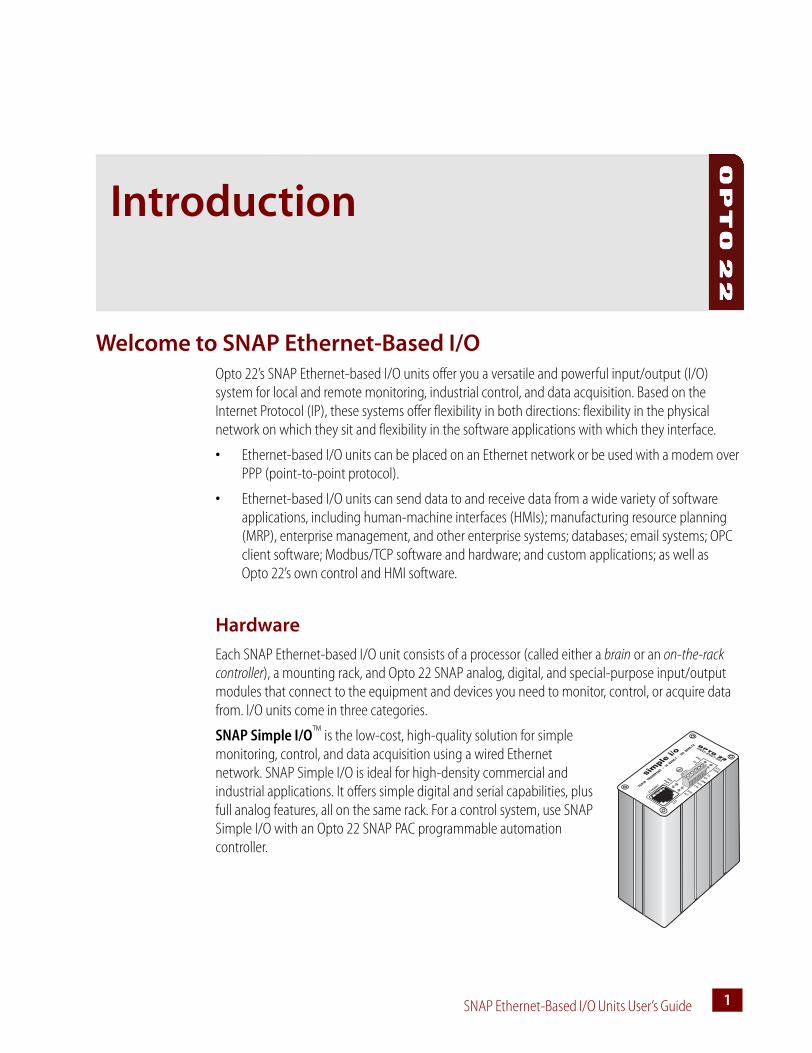
Each SNAP Ethernet-based I/O unit consists of a processor (called either a brain or an on-the-rack controller), a mounting rack, and Opto 22 SNAP analog, digital, and special-purpose input/output modules that connect to the equipment and devices you need to monitor, control, or acquire data from. I/O units come in three categories.
SNAP Simple I/O™ is the low-cost, high-quality solution for simple monitoring, control, and data acquisition using a wired Ethernet network. SNAP Simple I/O is ideal for high-density commercial and industrial applications. It offers simple digital and serial capabilities, plus full analog features, all on the same rack. For a control system, use SNAP Simple I/O with an Opto 22 SNAP PAC programmable automation controller.

WELCOME TO SNAP ETHERNET-BASED I/O
SNAP Ethernet-Based I/O Units User’s Guide2
SNAP Ethernet I/O™ offers rich analog, digital, and serial features, including high-speed counting (20 kHz), quadrature counters, events and reactions, PID loops, thermocouple linearization, output clamping, and much more. Racks hold 4, 8, 12, or 16 modules. For control, use SNAP Ethernet I/O units with one of Opto 22’s SNAP PAC programmable automation controllers. All models can use a wired network or modem over point-to-point protocol (PPP).
SNAP Ultimate I/O adds the ability to run flowchart-based control strategies on the I/O unit. You develop these strategies with ioControl™ software, which is included with the purchase of a SNAP Ultimate on-the-rack controller. SNAP Ultimate I/O can also control other Ethernet-based I/O units for an extended system. All models run on a wired network or a modem over PPP.
NOTE: For new development, Opto 22 recommends a SNAP PAC R-series on-the-rack controller instead of SNAP Ultimate I/O.
For a detailed comparison of models and features, see specifications and comparison charts starting on page 35.
Software
All Ethernet-based I/O units are programmed with Opto 22’s ioProject™ software.
ioProject Basic is included with your purchase of SNAP Ultimate I/O. It is also available for download from our website, www.opto22.com. ioProject Basic includes:
• ioControl™, a graphical, flowchart-based programming tool for developing software applications to monitor, control, and acquire date from equipment, processes, and devices. In addition to flowchart programming, ioControl includes a powerful, built-in scripting language based on C and other procedural languages.
• ioDisplay™, an intuitive package for building operator interfaces (HMIs) for your Microsoft® Windows®-based clients communicating with a SNAP Ultimate I/O system. ioDisplay offers a full-featured HMI including alarming, trending, security, and a built-in library of 3,000 industrial automation graphics.
• ioManager™, a utility application used to assign IP addresses, configure I/O points and I/O unit features, and inspect, read, and write to I/O units on a one-time basis. For multiple I/O units that use the same configuration, you can configure all I/O units simultaneously.
For communication with OPC clients, purchase OptoOPCServer™, an OLE for Process Control (OPC) 2.0-compliant server. OptoOPCServer can be purchased separately or as part of ioProject Professional, which also includes additional features in ioControl and ioDisplay. For more information on ioProject, see the ioProject Data Sheet (form #1472) on our website, www.opto22.com.

CHAPTER 1: INTRODUCTION
SNAP Ethernet-Based I/O Units User’s Guide 33
In addition to the ioProject software suite, SNAP Ethernet-based I/O units are compatible with the following:
• If you are already using Modbus®/TCP, you do not need additional software. The Modbus/TCP memory map and instructions for use are included in this guide.
• If you need to write your own custom applications in Visual Basic® or C++®, our OptoMMP™ Communication Toolkit (previously called the SNAP Ethernet I/O Driver Toolkit) with ActiveX components and C++ classes is included on the CD that came with the brain or controller. For instructions, see Opto 22 form #1465, the OptoMMP Protocol Guide, also included on the CD.
• If you are programming for Linux® or another operating system other than Microsoft® Windows®, the OptoMMP memory-mapped protocol for communicating with Ethernet-based I/O units is open and documented in Opto 22 form #1465, the OptoMMP Protocol Guide, included on the CD that came with the brain.
About this GuideThis guide shows you how to install and use SNAP Ethernet-based I/O units. This guide assumes that you have some familiarity with TCP/IP and Ethernet networking. If you are not familiar with these subjects, we strongly suggest you consult commercially available resources to learn about them before attempting to install or use SNAP Ethernet-based I/O units.
If you are using Modbus/TCP for communicating with SNAP Ethernet-based I/O units, this guide assumes that you are already familiar with Modbus/TCP.
The following sections are included in this user’s guide:
Chapter 1, “Introduction”—information about the guide and how to reach Opto 22 Product Support.
Chapter 2, “Installing a SNAP Ethernet-Based I/O Unit”—quick-start steps to get SNAP Ethernet-based I/O units up and running quickly.
Chapter 3, “System Architecture”—conceptual information on networking and communicating with SNAP Ethernet-based I/O units; comparisons of SNAP Ultimate, SNAP Ethernet, and SNAP Simple I/O features and capabilities; specifications for SNAP Ethernet-based brains.
Chapter 4, “Maintaining the Ethernet-Based I/O Unit”—assigning and changing IP addresses, resetting the I/O unit to factory defaults, and upgrading firmware.
Chapter 5, “Troubleshooting”—tips for resolving difficulties you may encounter while working with SNAP Ethernet-based I/O units.
Appendix A, “Using Modbus/TCP”—Use this appendix only if you are communicating with SNAP Ethernet-based I/O units using Modbus/TCP. The chapter includes Modbus function codes, I/O point referencing for Modbus, and the Modbus memory map.
Appendix B, “SNAP I/O Wiring Diagrams”—diagrams for wiring SNAP I/O analog, digital, and serial modules to the devices they monitor and control, along with information on racks and power supplies.

ABOUT THIS GUIDE
SNAP Ethernet-Based I/O Units User’s Guide4
Information Key
This guide includes information that applies to some types of Ethernet-based I/O units but not to others. Sections are marked as follows to indicate the products that support them:
Other Documents You May Need
See the following additional guides for the information listed. All guides are available on the Opto 22 website, www.opto22.com; some are included on the CD that came with the SNAP Ethernet-based brain or controller.
This text Indicates support by this hardware
UIO SNAP Ultimate I/O
EIO SNAP Ethernet I/O
SIO SNAP Simple I/O
For this information See this guide Form #
Configuring I/O points and system functions ioManager User’s Guide 1440
Designing flowchart-based control programs for the system (requires a SNAP PAC S-series or R-series, SNAP Ultimate I/O, or a SNAP-LCE industrial con-troller)
ioControl User’s Guide 1300
ioControl Command Reference 1301
ioControl Commands Quick Reference Card 1314
Communicating with I/O units using OPC OptoOPCServer User’s Guide 1439
Programming your own applications for SNAP Ether-net-based I/O units using the OptoMMP Communi-cation Toolkit (previously called the SNAP Ethernet I/O Driver Toolkit) or the OptoMMP memory-mapped protocol
OptoMMP Protocol Guide 1465

CHAPTER 1: INTRODUCTION
SNAP Ethernet-Based I/O Units User’s Guide 55
For HelpIf you have problems installing or using SNAP Ethernet-based I/O units and cannot find the help you need in this guide or on our website, contact Opto 22 Product Support.
Phone: 800-TEK-OPTO (835-6786)951-695-3080(Hours are Monday through Friday, 7 a.m. to 5 p.m. Pacific Time)
Fax: 951-695-3017
Email: [email protected]
Opto 22 Web site: support.opto22.com
When calling for technical support, be prepared to provide the following information about your system to the Product Support engineer:
• Software and version being used
• Brain and controller firmware version (as applicable)
• PC configuration (type of processor, speed, memory, and operating system)
• A complete description of your hardware and operating systems, including:
– jumper configuration
– loader and kernel versions for the brain, and date codes of I/O units (available through ioManager; see page 64.)
– IP addresses and net masks for devices on the system
– accessories installed (such as expansion cards)
– type of power supply
– third-party devices installed (for example, barcode readers)
• Specific error messages seen.
NOTE: Email messages and phone calls to Opto 22 Product Support are grouped together and answered in the order received.

FOR HELP
SNAP Ethernet-Based I/O Units User’s Guide6

SNAP Ethernet-Based I/O Units User’s Guide 77
Chapter 2
Installing a SNAP Ethernet-Based I/O Unit
If you already know how you will use the SNAP Ethernet-based I/O unit and want to get it running quickly, follow the sections in this chapter.
To learn about communication options and networking, start on page 21. Specifications are listed on page 35.
What You Will NeedYou’ll need the following items to install a SNAP Ethernet-based I/O unit:
• PC running Microsoft® Windows® 2000 or higher, with a 10/100 MB Ethernet adapter card, the TCP/IP protocol installed, and a valid IP address, on the same subnet as the I/O unit. (For more information, see “Networking” on page 32.)
• Crossover cable (for direct connection to the PC), or an available connection to a standard 10BASE-T or 100BASE-TX Ethernet network.
• SNAP Ultimate, SNAP Ethernet, or SNAP Simple I/O processor (See page 37 for a chart comparing models.)
• SNAP mounting rack and SNAP I/O modules. Choose rack and modules based on your needs. Make sure the rack is compatible with your brain or controller model (see page 91).
• A SNAP-PS5 or SNAP-PS5U power supply or other 5 VDC power supply (-0/+0.1 VDC at 4.0 A) applied to the rack. Additional power may be required for SNAP I/O modules and depends on the number and type of modules used. For more information, see “Determining Power Requirements” on page 95.
Installing SoftwareIn your CD-ROM drive, insert the CD that came with the brain or controller. The installation wizard should start automatically. If it doesn’t, use Windows Explorer to navigate to your CD-ROM drive and then double-click setup.exe. Follow directions to install the software.

INSTALLING HARDWARE
SNAP Ethernet-Based I/O Units User’s Guide8
Installing HardwareAssemble the rack and power supply according to the directions that came with them. For help with wiring, see “SNAP I/O Wiring Diagrams” on page 91 or the product data sheets, which are available on our website at www.opto22.com.
Installing Modules on the Rack
Modules snap into place in the row of connectors on the rack. Each module connector has a number.
CAUTION: Make sure you are using the correct rack for your processor (see chart on page 92). Using the wrong rack will severely damage the processor.
1. Place the rack so that the module connector numbers are right-side up, with zero on the left. (If your rack has screw connectors, the screw connectors will be at the bottom.)
2. Position the module over the module connector, aligning the small slot at the base of the module with the retention bar on the rack.
3. With the module correctly aligned over the connector, push on the module to snap it into place.
When positioning modules next to each other, be sure to align the male and female module keys (shown in the detailed view in the illustration at right) before snapping a module into position.
Modules snap securely into place and require a special tool (provided) to remove them. To remove a module, see page 9.
Module Module connectors Brain
Rack shown without screw connectors.
Retention bar

CHAPTER 2: INSTALLING A SNAP ETHERNET-BASED I/O UNIT
SNAP Ethernet-Based I/O Units User’s Guide 99
4. (Optional) As shown in the photo at right, use standard 4-40 x 1/4 truss-head Phillips hold-down screws to secure both sides of each module.
CAUTION: Do not over-tighten screws.
5. Plug the wiring connector into each module to attach modules to the devices they monitor.
Wiring diagrams are in Appendix B, “SNAP I/O Wiring Diagrams,” and in the module’s data sheet.
Removing a Module
1. If the modules are held in place with screws, remove them.
2. Holding the SNAP module tool (provided) as shown in the illustration at right, insert it into the notch at the base of the module.
3. Squeeze the module tool against the module to open the release latch, and pull straight up on the module to remove it.
4. Continue with “Installing the Brain or Controller” on page 10.

INSTALLING HARDWARE
SNAP Ethernet-Based I/O Units User’s Guide10
Installing the Brain or Controller
CAUTION: Make sure you install the processor (brain or on-the-rack controller) on the correct rack (see page 92). Using the wrong rack will severely damage the processor.
1. Remove the brain from its packaging.
2. Turn off power to the rack assembly.
3. Align the brain connector with the mating connector on the mounting rack, as shown in the diagram at right.
4. Seat the brain onto the connector and use the hold-down screw to secure the brain in position. Do not overtighten.
5. Using Category 5 or superior solid unshielded twisted-pair cable, connect the brain in one of the following ways:
– (Recommended for initial configuration) Connect to a PC directly, using an Ethernet crossover cable.
– Connect to a standard 10BASE-T or 100BASE-TX Ethernet network that has a PC on the same subnet as the brain and does NOT have a Dynamic Host Configuration Protocol (DHCP) server.
Maximum cable or segment length is 100 meters; minimum cable length is one meter. For more information on cables, see page 32.
6. For brains used with a modem: Also see “Using PPP Over a Modem” on page 12.
7. Before turning on power to the rack, follow instructions in Opto 22 form #1440, the ioManager User’s Guide, to assign an IP address to the I/O unit.
This guide is in Adobe Acrobat PDF format on the CD that came with the brain or controller and is also available from our website, www.opto22.com.

CHAPTER 2: INSTALLING A SNAP ETHERNET-BASED I/O UNIT
SNAP Ethernet-Based I/O Units User’s Guide 1111
What’s Next?To start configuring I/O units and I/O points, see “Configuring I/O,” below.
To learn more about SNAP Ethernet-based I/O unit capabilities and network options, see Chapter 3, “System Architecture.”
To use OLE for process control (OPC) with SNAP Ethernet-based I/O units, purchase the OptoOPCServer and see Opto 22 form #1439, the OptoOPCServer User’s Guide.
To communicate with I/O units using Modbus/TCP, see Appendix A, “Using Modbus/TCP.”
To program your own applications, see Opto 22 form #1465, the OptoMMP Protocol Guide.
Configuring I/O
No matter how you communicate with SNAP Ethernet-based I/O units, you will need to configure I/O points and I/O unit features.
If you are not using ioControl (Opto 22’s flowchart-based control software), follow instructions in the ioManager User’s Guide (Opto 22 form #1440).
If you are using ioControl, I/O units and points must be configured to match the ioControl strategy you will run. You can configure most Ethernet-based I/O unit and point functions either in ioControl or in ioManager.
For most I/O units, if you are already in ioControl, configuration is easier there and you can use the loopback IP address for SNAP Ultimate I/O units controlling themselves. However, some functions for Ethernet-based I/O units cannot be configured in ioControl.
If you use ioManager, you can save your configuration to a file, load it to multiple I/O units at once, and use it for referencing points in OPC. However, you cannot use the loopback address in ioManager.
Choose your configuration tool based on what you need to do:
Whichever tool you use for configuring I/O, be aware of the impact if you later change configuration. For example, if you configure I/O in ioManager, download the configuration file to I/O units, and then later add a point in ioControl, remember that your configuration file doesn’t contain that point.
Use ioControl for I/O configuration if Use ioManager for I/O configuration if
• You have only one I/O unit or I/O unit configurations are different.
• The strategy will run on SNAP Ultimate I/O units that are controlling themselves using the loopback IP address, 127.0.0.1
• You are using an Ethernet network for communications.
• The strategy handles all logic; you are not also configuring events and reactions on I/O units.
• You have multiple I/O units whose configurations are exactly the same or similar.
• You are using a modem connection (PPP) or SNMP.
• You are using event messages or email.• You are configuring events and reactions on the
I/O unit in addition to strategy logic.• You are using OPC to communicate with I/O
units.• You are not using ioControl.
USING PPP OVER A MODEM
SNAP Ethernet-Based I/O Units User’s Guide12
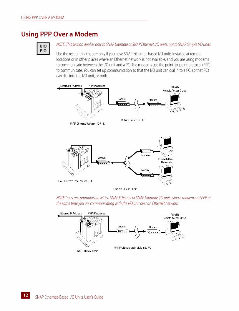
Using PPP Over a ModemNOTE: This section applies only to SNAP Ultimate or SNAP Ethernet I/O units, not to SNAP Simple I/O units.
Use the rest of this chapter only if you have SNAP Ethernet-based I/O units installed at remote locations or in other places where an Ethernet network is not available, and you are using modems to communicate between the I/O unit and a PC. The modems use the point-to-point protocol (PPP) to communicate. You can set up communication so that the I/O unit can dial in to a PC, so that PCs can dial into the I/O unit, or both.
NOTE: You can communicate with a SNAP Ethernet or SNAP Ultimate I/O unit using a modem and PPP at the same time you are communicating with the I/O unit over an Ethernet network.
UIOEIO
CHAPTER 2: INSTALLING A SNAP ETHERNET-BASED I/O UNIT
SNAP Ethernet-Based I/O Units User’s Guide 1313
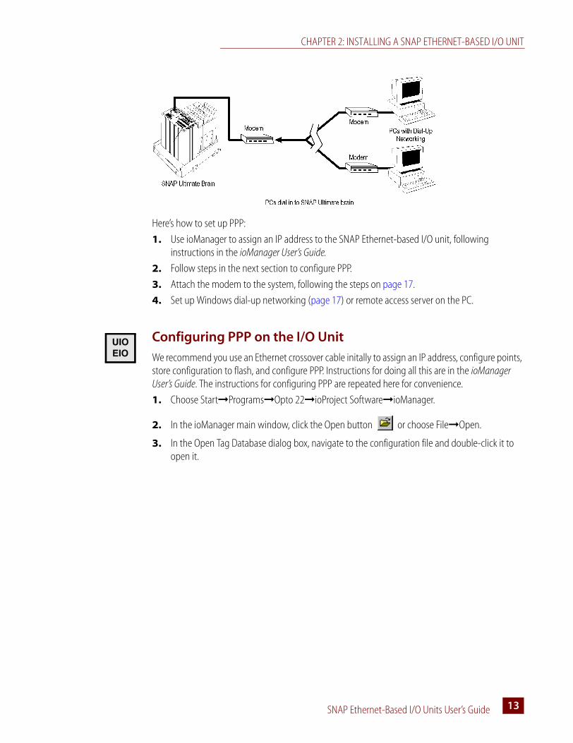
Here’s how to set up PPP:
1. Use ioManager to assign an IP address to the SNAP Ethernet-based I/O unit, following instructions in the ioManager User’s Guide.
2. Follow steps in the next section to configure PPP.
3. Attach the modem to the system, following the steps on page 17.
4. Set up Windows dial-up networking (page 17) or remote access server on the PC.
Configuring PPP on the I/O Unit
We recommend you use an Ethernet crossover cable initally to assign an IP address, configure points, store configuration to flash, and configure PPP. Instructions for doing all this are in the ioManager User’s Guide. The instructions for configuring PPP are repeated here for convenience.
1. Choose Start➞Programs➞Opto 22➞ioProject Software➞ioManager.
2. In the ioManager main window, click the Open button or choose File➞Open.
3. In the Open Tag Database dialog box, navigate to the configuration file and double-click it to open it.
UIOEIO
USING PPP OVER A MODEM
SNAP Ethernet-Based I/O Units User’s Guide14
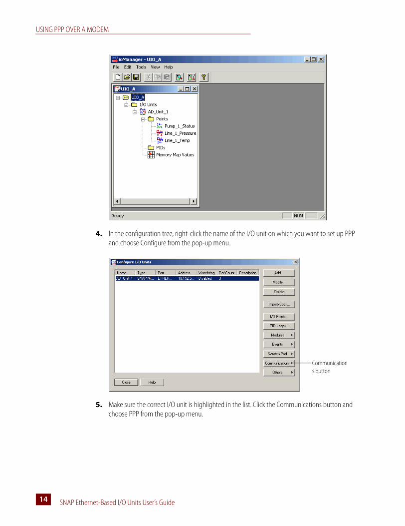
4. In the configuration tree, right-click the name of the I/O unit on which you want to set up PPP and choose Configure from the pop-up menu.
5. Make sure the correct I/O unit is highlighted in the list. Click the Communications button and choose PPP from the pop-up menu.
Communications button

CHAPTER 2: INSTALLING A SNAP ETHERNET-BASED I/O UNIT
SNAP Ethernet-Based I/O Units User’s Guide 1515
6. Complete the fields as follows:A Enter the Local IP Address for the PPP interface on the I/O unit. Enter the local Subnet Mask
only if you are using classless IP addressing. If you are not using classless IP addressing, leave the Subnet Mask at zero, and the I/O unit will calculate the subnet mask.
IMPORTANT: The network address for the PPP interface must be different from the network ID for the Ethernet interface. (The network address is obtained by ANDing the IP address and the subnet mask.)
B Enter the maximum number of times a login/password combination can be retried. C If you want outgoing PPP to always be connected, so there is no need for the I/O unit to dial
out, check this box.D Change the modem initialization string and modem hangup string if necessary. Make sure
you use the setting to ignore DTR signal in the modem initialization string:
The default modem initialization string is AT&D0^M~~~~
Consult the command reference that came with your modem to determine the correct initialization command strings. A sample modem initialization string might look like this:
AT&F^M~~AT&D0&K0^M~~AT&W0^M~~AT&Y0^M~~
The &F command sets the modem back to factory defaults. The ^M tells the Ethernet I/O unit to insert a carriage return. The ~ tells it to insert a 500ms pause. The &W0 writes the current settings to NVRAM profile 0 on the modem. The &Y0 instructs the modem to use NVRAM profile 0 after resetting.
This initialization string is just a sample; command strings for your modem may differ.
ABCD
EF

USING PPP OVER A MODEM
SNAP Ethernet-Based I/O Units User’s Guide16
E If the I/O unit will send outgoing calls, complete the Outgoing PPP section:
Choose Enabled from the drop-down list.
In the Use Local IP Address field, choose Yes to have the I/O unit use the Local IP Address you entered for the PPP link; choose No to have the remote device assign the I/O unit an IP address for the PPP link. The default is No.
If you want the I/O unit to use the device the I/O unit is calling as the default gateway for all communication, choose Yes for Set As Default Gateway. The default is No.
Enter the Login and Password the I/O unit should use for authentication when it calls the remote device.
In the Phone number field, enter the number the modem should dial for outgoing calls from the I/O unit.
Change the following fields if necessary:– Inactivity Timeout—If the I/O unit sends no packets and receives no packets for this
number of seconds after the PPP session is negotiated, the modem will hang up. The default is 30.
– Max Connect Time—The maximum amount of time in seconds an outgoing PPP connection can stay connected after successful negotiation. Default is zero, which disables the timer.
– Max Dial Retries—The number of times the I/O unit will redial if the first attempt fails. Default is zero.
– Retry Interval—The number of seconds the I/O unit will wait before trying to redial after the first attempt fails. Default is zero.
– Disable Time—If the maximum connect time or maximum number of retries has been reached, the outgoing PPP dialer waits this number of seconds before doing anything. Default is zero.
F If the I/O unit will receive incoming calls via modem, complete the Incoming PPP section:
Choose Enabled from the drop-down list so the modem will listen for incoming calls.
If you want the I/O unit to use the device calling the I/O unit as the default gateway for all communication, choose Yes for Set As Default Gateway. The default is No.
Change the Inactivity Timeout if necessary. The default is 30.
Enter the Login and Password the I/O unit should accept for incoming calls.
In the Remote IP Address field, enter the IP address the I/O unit should give to devices that dial into the I/O unit and ask for an address. This address must be on the same subnet as the local IP address.
Enter a modem listen string to make sure the modem automatically answers calls. The default modem listen string is ATS0=1^M~ , which instructs the modem to answer any incoming calls on the first ring. Again, refer to your modem’s command reference for the correct listen string.
7. When all fields are correct, click OK.
IMPORTANT: For the configuration to take effect, you must upload the configuration file to the I/O unit, save it to flash memory, and restart the I/O unit.

CHAPTER 2: INSTALLING A SNAP ETHERNET-BASED I/O UNIT
SNAP Ethernet-Based I/O Units User’s Guide 1717
8. Follow instructions in the ioManager User’s Guide to upload the configuration file to the brain.
If you wish, you can upload just once, after you have configured all items for the I/O unit: PPP, I/O points, security, and so on.
9. Continue with the next section to attach the modem to the I/O unit.
Attaching the Modem to the SNAP Ethernet-Based I/O Unit
Once the brain and I/O points are configured and communication has been tested, follow these steps to attach the modem to the I/O unit. To work properly with the I/O unit, a modem must be able to store settings in non-volatile RAM (NVRAM) and default to those settings on reset.
IMPORTANT: Any modem used with the controller must implement the Carrier Detect (CD) signal or use a custom cable that connects CD to Data Terminal Ready (DTR).
1. Follow the diagram at right to attach the modem to the I/O unit using the brain’s serial connector.
2. Store configuration settings to the modem’s NVRAM, following instructions in the user’s guide for your modem.
NOTE: Configuration settings must be stored to the modem’s NVRAM so they will be loaded when the SNAP Ethernet-based I/O unit sends a reset command to the modem.
3. If PCs will dial up the I/O unit, set up Windows dial-up networking on the PCs that will call the I/O unit. For Windows 2000, see page 17.
4. If you want the I/O unit to dial up a PC, set up a remote access server (RAS) on the PC.
Configuring Microsoft Windows Dial-up Networking on Windows 2000
Use the following settings to configure Windows dial-up networking on any PC that will dial in to the Ethernet-based .
1. Click Start and choose Settings➞Control Panel. Double-click Network and Dial-Up Connections.
2. Double-click Make New Connection. Follow directions in the wizard to create a new connection.
3. When the new connection is created, double-click its name in the Network and Dial-Up Connections window.
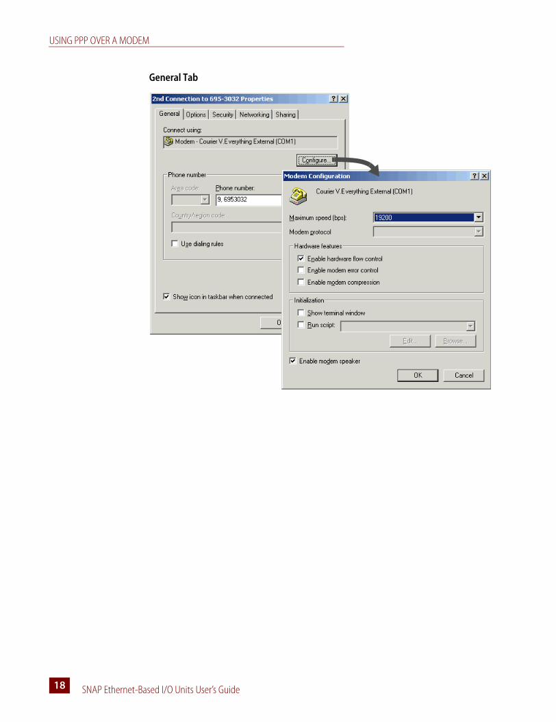
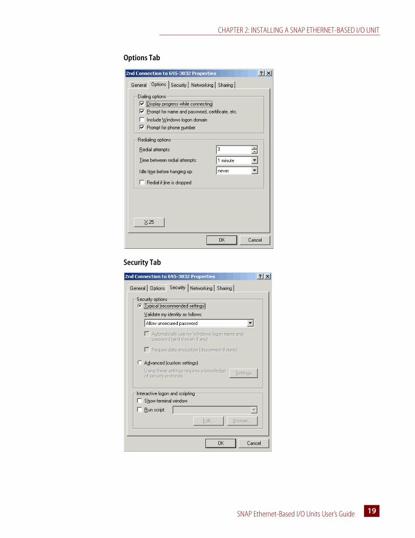
4. In the Properties dialog box, set each tab as shown in the following figures:
UIOEIO
USING PPP OVER A MODEM
SNAP Ethernet-Based I/O Units User’s Guide18
General Tab
CHAPTER 2: INSTALLING A SNAP ETHERNET-BASED I/O UNIT
SNAP Ethernet-Based I/O Units User’s Guide 1919
Options Tab
Security Tab

USING PPP OVER A MODEM
SNAP Ethernet-Based I/O Units User’s Guide20
Networking Tab
Sharing Tab

SNAP Ethernet I/O Units User’s Guide 2121
Chapter 3
System Architecture
This chapter explains how to use SNAP Ethernet-based I/O units in an Ethernet network and how to communicate with them. It includes information on:
Communication OptionsSNAP Ethernet-based I/O units communicate using TCP/IP or UDP/IP over a wired or wireless network.
Physical Layer—All SNAP Ethernet-based I/O units communicate over a 10- or 100-Mbps wired Ethernet link. SNAP Ethernet and SNAP Ultimate I/O units can also communicate using a modem over PPP.
Transport Layer—The key to SNAP Ethernet-based I/O unit communication flexibility is the transport layer, Internet Protocol (IP). Both the Transmission Control Protocol (TCP) and the User Datagram Protocol (UDP) are used with IP.
Application Layer—Because SNAP Ethernet-based I/O units use standard IP for the transport layer, many communication options are possible in the application layer. After the I/O unit is installed and has an IP address assigned (see page 10), you can communicate with it using the following methods:
• ioManager software utility is used for assigning IP addresses, configuring I/O points and features, and performing onetime reads and writes.
• ioControl strategies running on a SNAP Ultimate I/O system or on a SNAP-LCE industrial controller can configure, read, and write to I/O points on SNAP Ultimate, SNAP Ethernet, or SNAP Simple I/O units.
Communication options See below
System architecture See page 24
Networking See page 32
Specifications and feature comparison charts See page 35
UIOEIOSIO

COMMUNICATION OPTIONS
SNAP Ethernet I/O Units User’s Guide22
• Custom software applications are easy to develop using our OptoMMP Communication Toolkit with ActiveX components and C++ classes. They use an IEEE 1394-based protocol to read and write to SNAP Ethernet-based I/O units. For developers not using Microsoft Windows, our IEEE 1394-based protocol is open and documented.
• Modbus/TCP provides a direct connection with Modbus/TCP hardware or software or third-party software applications, which can read or write to I/O points on SNAP Ethernet-based I/O units.
• OPC (OLE for Process Control) uses OptoOPCServer to serve I/O unit data to any OPC 2.0-compliant application, such as an HMI, which can also read or write to I/O points. OptoOPCServer can be purchased separately or as part of the ioProject Professional software suite.
• SMTP (Simple Mail Transfer Protocol) connects a SNAP Ultimate or SNAP Ethernet I/O unit with corporate email servers, so employees can be emailed or paged if there’s a problem on devices attached to the I/O unit.
• SNMP (Simple Network Management Protocol) makes it possible to monitor devices attached to SNAP Ultimate or SNAP Ethernet I/O units just as you would any computer or server on the Ethernet network, using an SNMP-based enterprise management system such as Computer Associates’ Unicenter®, Hewlett-Packard’s OpenView®, or IBM’s Tivoli®. When a monitored event occurs, such as a door left open or a pressure level too high, the I/O unit sends an SNMP trap to the management system.
• FTP (File Transfer Protocol) can be used to transfer files and data to and from the SNAP Ultimate I/O system, whether to custom applications, enterprise databases, or any file system.
• OptoControl strategies running on a SNAP-LCM4 industrial controller with an M4SENET-100 Ethernet adapter card can configure, read, and write to I/O points on SNAP Ethernet or SNAP Simple I/O units. (NOTE: OptoControl and the FactoryFloor software suite are not recommended for new installations. Use ioControl and ioProject instead.)
Simultaneous Communication
In addition to communicating using all the methods listed above for the type of I/O unit, each SNAP Ethernet-based I/O unit can also communicate simultaneously using all applicable methods.
The reason lies in the nature of IP. In serial communication, a single data request is sent by one device to another. The first device must wait for a response before any additional communication can be carried out. IP, however, can establish multiple simultaneous sessions, so many data requests can be sent at once without waiting for any individual response. Each request gets a response, but the link isn’t idle while waiting for responses.
In addition, IP can simultaneously handle multiple requests from multiple devices. A PC can communicate with all SNAP Ethernet-based I/O units on the same network—all at the same time—and multiple PCs can communicate with one I/O unit at the same time.
So, for example, a SNAP Ethernet-based I/O unit can respond to directions from a Modbus master, give analog point data to a technician using ioManager, and carry out instructions from a custom C++ application—all at once.
UIOEIOSIO
UIOEIOSIO
UIOEIOSIO
UIOEIO
UIOEIO
UIO
EIOSIO
CHAPTER 3: SYSTEM ARCHITECTURE
SNAP Ethernet I/O Units User’s Guide 2323
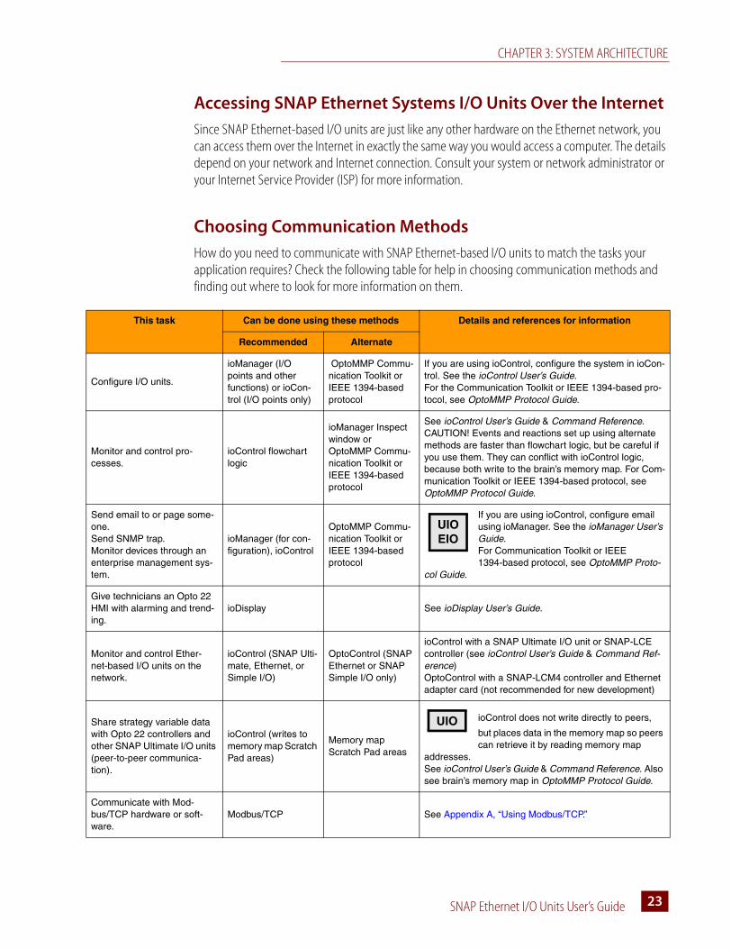
Accessing SNAP Ethernet Systems I/O Units Over the Internet
Since SNAP Ethernet-based I/O units are just like any other hardware on the Ethernet network, you can access them over the Internet in exactly the same way you would access a computer. The details depend on your network and Internet connection. Consult your system or network administrator or your Internet Service Provider (ISP) for more information.
Choosing Communication Methods
How do you need to communicate with SNAP Ethernet-based I/O units to match the tasks your application requires? Check the following table for help in choosing communication methods and finding out where to look for more information on them.
This task Can be done using these methods Details and references for information
Recommended Alternate
Configure I/O units.
ioManager (I/O points and other functions) or ioCon-trol (I/O points only)
OptoMMP Commu-nication Toolkit or IEEE 1394-based protocol
If you are using ioControl, configure the system in ioCon-trol. See the ioControl User’s Guide. For the Communication Toolkit or IEEE 1394-based pro-tocol, see OptoMMP Protocol Guide.
Monitor and control pro-cesses.
ioControl flowchart logic
ioManager Inspect window or OptoMMP Commu-nication Toolkit orIEEE 1394-based protocol
See ioControl User’s Guide & Command Reference.CAUTION! Events and reactions set up using alternate methods are faster than flowchart logic, but be careful if you use them. They can conflict with ioControl logic, because both write to the brain’s memory map. For Com-munication Toolkit or IEEE 1394-based protocol, see OptoMMP Protocol Guide.
Send email to or page some-one.Send SNMP trap. Monitor devices through an enterprise management sys-tem.
ioManager (for con-figuration), ioControl
OptoMMP Commu-nication Toolkit or IEEE 1394-based protocol
If you are using ioControl, configure email using ioManager. See the ioManager User’s Guide. For Communication Toolkit or IEEE 1394-based protocol, see OptoMMP Proto-
col Guide.
Give technicians an Opto 22 HMI with alarming and trend-ing.
ioDisplay See ioDisplay User’s Guide.
Monitor and control Ether-net-based I/O units on the network.
ioControl (SNAP Ulti-mate, Ethernet, or Simple I/O)
OptoControl (SNAP Ethernet or SNAP Simple I/O only)
ioControl with a SNAP Ultimate I/O unit or SNAP-LCE controller (see ioControl User’s Guide & Command Ref-erence) OptoControl with a SNAP-LCM4 controller and Ethernet adapter card (not recommended for new development)
Share strategy variable data with Opto 22 controllers and other SNAP Ultimate I/O units (peer-to-peer communica-tion).
ioControl (writes to memory map Scratch Pad areas)
Memory map Scratch Pad areas
ioControl does not write directly to peers,
but places data in the memory map so peers can retrieve it by reading memory map
addresses. See ioControl User’s Guide & Command Reference. Also see brain’s memory map in OptoMMP Protocol Guide.
Communicate with Mod-bus/TCP hardware or soft-ware.
Modbus/TCP See Appendix A, “Using Modbus/TCP.”
UIOEIO
UIO

SYSTEM ARCHITECTURE—SNAP SIMPLE I/O
SNAP Ethernet I/O Units User’s Guide24
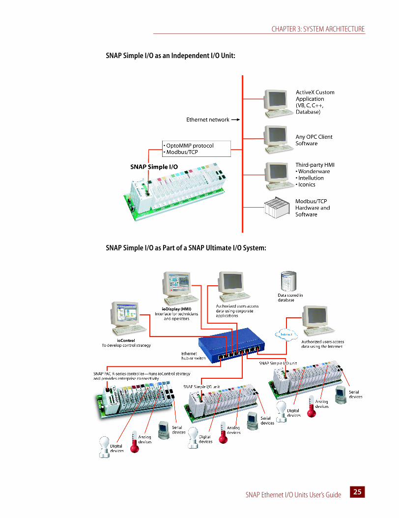
System Architecture—SNAP Simple I/OSNAP Simple I/O can be used in two ways:
• As part of a larger control system:
– A system running ioControl (on a SNAP PAC or SNAP-LCE controller or on SNAP Ultimate I/O)
– A system running OptoControl™ on a legacy SNAP-LCM4 controller with an M4SENET-100 Ethernet adapter card (not recommended for new installations; use ioControl and a SNAP PAC controller instead)
• As an independent I/O unit. You can communicate with an independent Simple I/O unit using Modbus/TCP, the OptoOPCServer (available separately), or applications you develop using the free OptoMMP Communication Toolkit or our IEEE 1394-based protocol.
The following diagrams illustrate these two uses.
Exchange I/O point data with third-party software such as HMIs.
OptoOPCServer and brain’s memory map
Purchase OptoOPCServer separately. See OptoOPC-Server User’s Guide and the memory map in OptoMMP Protocol Guide.
Exchange ioControl strategy variable data with third-party software such as HMIs.
FTP and brain’s file system (SNAP Ulti-mate I/O only)
OptoOPCServer Purchase OptoOPCServer separately. See ioControl User’s Guide and OptoOPCServer User’s Guide.
Write your own software application to communicate with the system.
C++ or Active X: OptoMMP Communi-cation Toolkit and brain’s memory map.
Opto 22’s IEEE 1394-based proto-col and brain’s memory map.
See OptoMMP Protocol Guide.
This task Can be done using these methods Details and references for information
Recommended Alternate
CHAPTER 3: SYSTEM ARCHITECTURE
SNAP Ethernet I/O Units User’s Guide 2525
SNAP Simple I/O as an Independent I/O Unit:
SNAP Simple I/O as Part of a SNAP Ultimate I/O System:

SYSTEM ARCHITECTURE—SNAP ETHERNET I/O
SNAP Ethernet I/O Units User’s Guide26
System Architecture—SNAP Ethernet I/OLike SNAP Simple I/O, SNAP Ethernet I/O can be used as part of a larger control system or as an independent I/O unit.
• As part of a larger control system:
– A system running ioControl (on a SNAP PAC or SNAP-LCE controller or on SNAP Ultimate I/O)
– A system running OptoControl™ on a legacy SNAP-LCM4 controller with an M4SENET-100 Ethernet adapter card (not recommended for new installations; use ioControl and a SNAP PAC controller instead)
• As an independent I/O unit—You can communicate with an independent SNAP Ethernet I/O unit using Modbus/TCP, the OptoOPCServer, SNMP, SMTP, or applications you develop using the free OptoMMP Communication Toolkit or our IEEE 1394-based protocol.
System Architecture—SNAP Ultimate I/OBecause SNAP Ultimate brains are a combination of controller and I/O processor, their architecture is more complex than that of SNAP Simple and SNAP Ethernet brains, which are I/O processors only. This next few pages show the capabilities of this versatile system, starting with the simplest and moving to the more complex. Your application may require only some of these capabilities, but as your needs expand, remember that SNAP Ultimate I/O can be used in all the ways shown, simultaneously.
Understanding the SNAP Ultimate Brain
The SNAP Ultimate brain merges two functions that are usually located in separate pieces of hardware: input/output processing and flowchart-based control. These two functions are handled by two “sides” of the brain, as illustrated in the next diagram.
CHAPTER 3: SYSTEM ARCHITECTURE
SNAP Ethernet I/O Units User’s Guide 2727
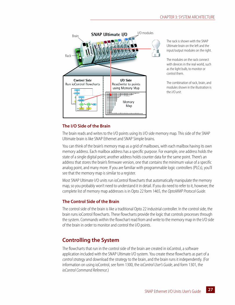
The I/O Side of the Brain
The brain reads and writes to the I/O points using its I/O side memory map. This side of the SNAP Ultimate brain is like SNAP Ethernet and SNAP Simple brains.
You can think of the brain’s memory map as a grid of mailboxes, with each mailbox having its own memory address. Each mailbox address has a specific purpose. For example, one address holds the state of a single digital point; another address holds counter data for the same point. There’s an address that stores the brain’s firmware version, one that contains the minimum value of a specific analog point, and many more. If you are familiar with programmable logic controllers (PLCs), you’ll see that the memory map is similar to a register.
Most SNAP Ultimate I/O units run ioControl flowcharts that automatically manipulate the memory map, so you probably won’t need to understand it in detail. If you do need to refer to it, however, the complete list of memory map addresses is in Opto 22 form 1465, the OptoMMP Protocol Guide.
The Control Side of the Brain
The control side of the brain is like a traditional Opto 22 industrial controller. In the control side, the brain runs ioControl flowcharts. These flowcharts provide the logic that controls processes through the system. Commands within the flowchart read from and write to the memory map in the I/O side of the brain in order to monitor and control the I/O points.
Controlling the System
The flowcharts that run in the control side of the brain are created in ioControl, a software application included with the SNAP Ultimate I/O system. You create these flowcharts as part of a control strategy and download the strategy to the brain, and the brain runs it independently. (For information on using ioControl, see form 1300, the ioControl User’s Guide, and form 1301, the ioControl Command Reference.)
Brain
Rack
I/O modules
The rack is shown with the SNAP Ultimate brain on the left and the input/output modules on the right.
The modules on the rack connect with devices in the real world, such as the light bulb, to monitor or control them.
The combination of rack, brain, and modules shown in the illustration is the I/O unit.
SYSTEM ARCHITECTURE—SNAP ULTIMATE I/O
SNAP Ethernet I/O Units User’s Guide28
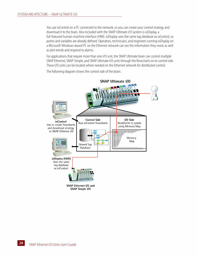
You use ioControl on a PC connected to the network, so you can create your control strategy and download it to the brain. Also included with the SNAP Ultimate I/O system is ioDisplay, a full-featured human-machine interface (HMI). ioDisplay uses the same tag database as ioControl, so points and variables are already defined. Operators, technicians, and engineers running ioDisplay on a Microsoft Windows-based PC on the Ethernet network can see the information they need, as well as plot trends and respond to alarms.
For applications that require more than one I/O unit, the SNAP Ultimate brain can control multiple SNAP Ethernet, SNAP Simple, and SNAP Ultimate I/O units through the flowcharts on its control side. These I/O units can be located where needed on the Ethernet network for distributed control.
The following diagram shows the control side of the brain:

CHAPTER 3: SYSTEM ARCHITECTURE
SNAP Ethernet I/O Units User’s Guide 2929
Communicating Peer-to-Peer on the Network
What if you have more than one SNAP Ultimate I/O unit, or multiple SNAP PAC and SNAP-LCE controllers? What if each one is running a different ioControl strategy, and they need to share variable data?
The following illustration shows how this type of peer-to-peer communication can be done.
The memory map in the brain’s I/O side has two parts: the fixed area and the Scratch Pad area.
The fixed memory area is used automatically by the brain to read and write data to I/O points; each address has a fixed purpose.
The Scratch Pad area, however, is user-defined; it is available for you to define and use as needed in order to exchange data among peers.
The Scratch Pad area includes four sections to accommodate different types of data: bits, integers, floats, and strings. The bit section is a 64-bit mask. Integer and float sections are tables of 10,240 four-byte elements. Strings are a table of 64 elements, each capable of holding 128 characters or 128 bytes of binary data.
Using ioControl commands in its flowcharts, the first Ultimate I/O unit can write strategy variable data to its Scratch Pad area. Other SNAP Ultimate I/O units, SNAP PAC or SNAP-LCE controllers, or even legacy SNAP-LCM4 controllers can use similar commands in their own flowcharts to read the data from the Scratch Pad area of the first I/O unit. Similarly, another unit or controller can write to the Scratch Pad area of the first I/O unit, which can then read the data deposited in its own Scratch Pad area by the peer. The reading and writing of data by peers to the Scratch Pad area must be very carefully coordinated in order to avoid conflicts.
For more information on using ioControl commands for peer-to-peer communication, see “Communication Commands” in Chapter 10 of the ioControl User’s Guide and individual commands in the ioControl Command Reference.
SYSTEM ARCHITECTURE—SNAP ULTIMATE I/O
SNAP Ethernet I/O Units User’s Guide30
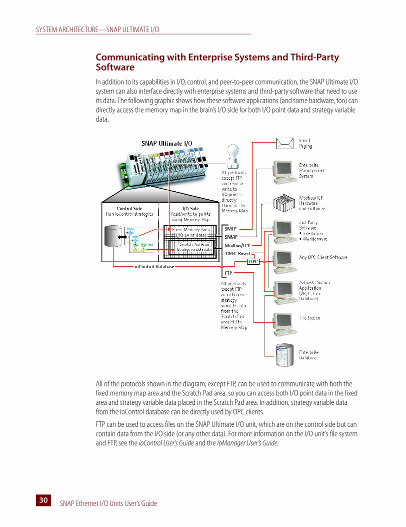
Communicating with Enterprise Systems and Third-Party Software
In addition to its capabilities in I/O, control, and peer-to-peer communication, the SNAP Ultimate I/O system can also interface directly with enterprise systems and third-party software that need to use its data. The following graphic shows how these software applications (and some hardware, too) can directly access the memory map in the brain’s I/O side for both I/O point data and strategy variable data.
All of the protocols shown in the diagram, except FTP, can be used to communicate with both the fixed memory map area and the Scratch Pad area, so you can access both I/O point data in the fixed area and strategy variable data placed in the Scratch Pad area. In addition, strategy variable data from the ioControl database can be directly used by OPC clients.
FTP can be used to access files on the SNAP Ultimate I/O unit, which are on the control side but can contain data from the I/O side (or any other data). For more information on the I/O unit’s file system and FTP, see the ioControl User’s Guide and the ioManager User’s Guide.
CHAPTER 3: SYSTEM ARCHITECTURE
SNAP Ethernet I/O Units User’s Guide 3131
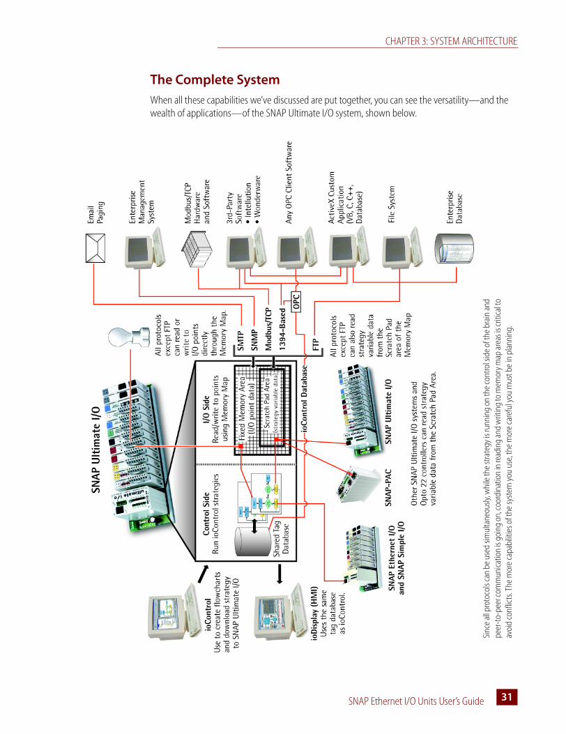
The Complete System
When all these capabilities we’ve discussed are put together, you can see the versatility—and the wealth of applications—of the SNAP Ultimate I/O system, shown below.
Sinc
e al
l pro
toco
ls ca
n be
use
d sim
ulta
neou
sly, w
hile
the
stra
tegy
is ru
nnin
g on
the
cont
rol s
ide
of th
e br
ain
and
peer
-to-
peer
com
mun
icatio
n is
goin
g on
, coo
rdin
atio
n in
read
ing
and
writ
ing
to m
emor
y map
are
as is
criti
cal t
o av
oid
conf
licts
. The
mor
e ca
pabi
litie
s of t
he sy
stem
you
use
, the
mor
e ca
refu
l you
mus
t be
in p
lann
ing.
NETWORKING
SNAP Ethernet I/O Units User’s Guide32
NetworkingFrom a physical standpoint, SNAP Ethernet-based I/O units can be networked in several ways:
• Connected directly to a PC or controller using a crossover cable
• Attached to an existing TCP/IP Ethernet network
• As part of an independent network built with standard Ethernet hardware
• Over a modem connection (SNAP Ethernet and SNAP Ultimate I/O units only)
The networking method you use depends on several things, including whether you need control or data acquisition, the number of PCs and I/O units you are using, the speed and volume of communication, security requirements, and the availability of an Ethernet network.
Connecting the I/O Unit Directly to a PC or Controller
A direct connection using a crossover cable connects just one SNAP Ethernet-based I/O unit with one host. If you need only one I/O unit and one host and have no existing Ethernet network, it’s ideal. A direct connection is quick, easy to do, and provides high speed and high security for a small system.
A direct connection is also useful for assigning an IP address, configuring I/O points, and testing applications on I/O units that will be used later on a network. The direct connection eliminates other variables that could interfere with communication, so you can focus on maintenance and troubleshooting.
Crossover Cables
Use an Ethernet crossover cable for direct connections. The crossover cable must be a minimum of one meter long. (Maximum length is 100 meters.) For reliability, we recommend you purchase the cable, rather than build it.
If you build your own crossover cable, you’ll need an RJ-45 male connector at each end. The cable includes four twisted pairs. Follow the illustration on the next page for wiring the connectors.
NOTE: The illustration shows both a straight-through cable and a crossover cable. The straight-through cable is used for connecting the brain to a hub on a standard Ethernet network. The crossover cable is used for direct connection to a PC or other host.
If you’re not sure which cable you have, hold up both ends so the connector tab is at the back of each end. Compare the color sequence of the wires in the connectors. If the sequence is identical for both connectors, it’s a straight-through cable. If the sequence is different, it’s a crossover cable.
UIOEIOSIO

CHAPTER 3: SYSTEM ARCHITECTURE
SNAP Ethernet I/O Units User’s Guide 3333
NOTE: Make sure you put 3 and 6 on the same pair, or you may experience noise and distance limitations. Also, make sure to include all pairs, since they are required for 100 Mbps.
Attaching the I/O Unit to an Existing Ethernet Network
The first rule in attaching SNAP Ethernet-based I/O units to an existing network is to work closely with your system administrator, who must determine network topology and hardware. Be sure to consider the impact on your existing network of adding the I/O units.
In addition, make sure the system administrator understands that each I/O unit must have a fixed (static) IP address, whether or not a Dynamic Host Configuration Protocol (DHCP) server is used on the network. For more information on IP addresses, see the ioManager User’s Guide.
If you are using SNAP Ethernet-based I/O units for data acquisition, you can place the I/O unit anywhere on an existing Ethernet network. If you are using the I/O unit with control applications, however, the network segment design will depend on the number of hosts, the number of data transactions, and issues of data security. With fewer hosts and fewer data transactions, data packet collisions are less likely and system performance improves. If collisions are a problem, and especially if you need high throughput and predictable response times, it’s best to put the I/O unit on a switched network segment. We recommend switches, not hubs. For best performance, use a 100 Mb network.
If you need to isolate the control system data from the main network backbone, consider using a router, network switch, or other gateway device. You can also use a SNAP PAC S-series controller, which has two Ethernet network interfaces: one interface can be connected to the enterprise network, and the other used for the control system. (For more information, see the SNAP PAC S-Series data sheet, form #1584).
UIOEIOSIO

NETWORKING
SNAP Ethernet I/O Units User’s Guide34
Using the I/O Unit in an Independent Network
The third way SNAP Ethernet-based I/O units can be used is by developing an independent network. An independent network gives a high level of communication speed and volume, as well as high security. If you have no existing Ethernet network, you can use off-the-shelf Ethernet components to build one.
You may also need a separate network for critical control applications. Again, the choice depends on your requirements for data transactions, data security, and whether a near-deterministic system is necessary.
If you are building your own network, remember that each I/O unit must have a fixed IP address. See the ioManager User’s Guide for more information on IP addresses.
Since Ethernet and TCP/IP are worldwide standards, there are a number of commercially available resources for learning about building and maintaining such a network. One excellent resource is the MCSE Training Guide: TCP/IP by New Riders Publishing; many others are also available. We strongly suggest you learn as much as possible about the subject and plan your network carefully before beginning, in order to get the best performance from your system.
Communicating with the System via Modem
A fourth way to use a SNAP Ethernet-based I/O unit (SNAP Ultimate and SNAP Ethernet I/O only) is with a modem connection. This use is ideal for remote installations (for example, a communication tower or a pipeline) or in other places where a wired Ethernet network is not practical. Communication via modem uses the Point-to-Point Protocol (PPP) over an RS-232 link instead of an Ethernet link.
The system can dial out to a PC connected to a modem, or the PC can dial into the system, or both. If the system is also communicating via Ethernet, the network ID for the PPP interface on the brain must be different from the brain’s Ethernet IP network ID.
For more details on configuring the brain for use with a modem, see “Using PPP Over a Modem” on page 12.
UIOEIOSIO
UIOEIO
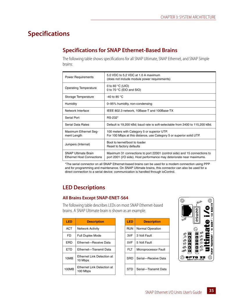
CHAPTER 3: SYSTEM ARCHITECTURE
SNAP Ethernet I/O Units User’s Guide 3535
Specifications
Specifications for SNAP Ethernet-Based Brains
The following table shows specifications for all SNAP Ultimate, SNAP Ethernet, and SNAP Simple brains:
LED Descriptions
All Brains Except SNAP-ENET-S64
The following table describes LEDs on most SNAP Ethernet-based brains. A SNAP Ultimate brain is shown as an example.
Power Requirements5.0 VDC to 5.2 VDC at 1.0 A maximum (does not include module power requirements)
Operating Temperature0 to 60 °C (UIO)0 to 70 °C (EIO and SIO)
Storage Temperature -40 to 85 °C
Humidity 0–95% humidity, non-condensing
Network Interface IEEE 802.3 network, 10Base-T and 100Base-TX
Serial Port RS-232*
Serial Data Rates Default is 19,200 kBd; baud rate is soft-selectable from 2400 to 115,200 kBd.
Maximum Ethernet Seg-ment Length
100 meters with Category 5 or superior UTP.For 100 Mbps at this distance, use Category 5 or superior solid UTP.
Jumpers (Internal)Boot to kernel/boot to loaderReset to factory defaults
SNAP Ultimate Brain Ethernet Host Connections
Maximum 31 connections to port 22001 (control side) and 15 connections to port 2001 (I/O side). Host performance may deteriorate near maximums.
*The serial connector on all SNAP Ethernet-based brains can be used for a modem connection using PPP and for programming and maintenance. On SNAP Ultimate brains, this connector can also be used for a direct connection to a serial device; communication is handled through ioControl.
LED Description LED Description
ACT Network Activity RUN Normal Operation
FD Full Duplex Mode 3VF 3 Volt Fault
ERD Ethernet—Receive Data 5VF 5 Volt Fault
ETD Ethernet—Transmit Data FLT Microprocessor Fault
10MBEthernet Link Detection at 10 Mbps
SRD Serial—Receive Data
100MBEthernet Link Detection at 100 Mbps
STD Serial—Transmit Data
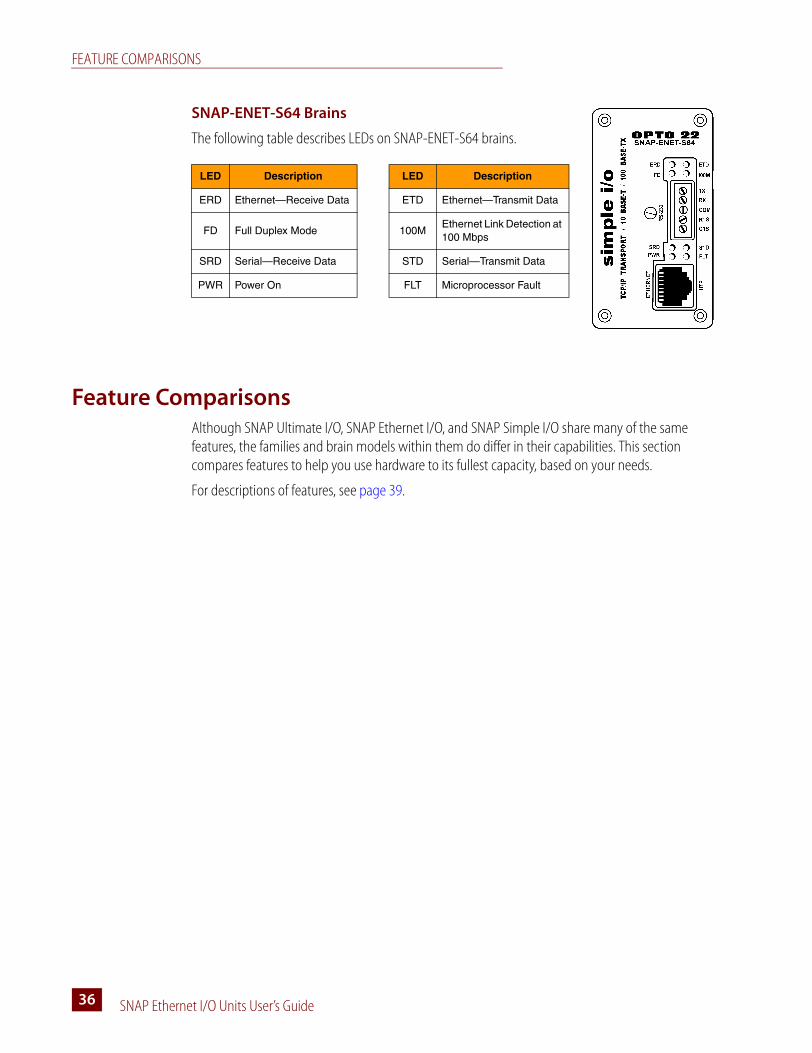
FEATURE COMPARISONS
SNAP Ethernet I/O Units User’s Guide36
SNAP-ENET-S64 Brains
The following table describes LEDs on SNAP-ENET-S64 brains.
Feature ComparisonsAlthough SNAP Ultimate I/O, SNAP Ethernet I/O, and SNAP Simple I/O share many of the same features, the families and brain models within them do differ in their capabilities. This section compares features to help you use hardware to its fullest capacity, based on your needs.
For descriptions of features, see page 39.
LED Description LED Description
ERD Ethernet—Receive Data ETD Ethernet—Transmit Data
FD Full Duplex Mode 100MEthernet Link Detection at 100 Mbps
SRD Serial—Receive Data STD Serial—Transmit Data
PWR Power On FLT Microprocessor Fault

CHAPTER 3: SYSTEM ARCHITECTURE
SNAP Ethernet I/O Units User’s Guide 3737
SNAP Ethernet-Based Brain Comparison Chart
This table compares Opto 22 Ethernet-based brains: SNAP Simple, SNAP Ethernet, and SNAP Ultimate.
FEATURE
SNAP Simple I/O
SNAP Ethernet I/O SNAP Ultimate I/O
SN
AP
-EN
ET-
S64
SN
AP
-B30
00-E
NE
TS
NA
P-E
NE
T-R
TC
SN
AP
-EN
ET-
D64
SN
AP
-UP
1-A
DS
SN
AP
-UP
1-D
64
SN
AP
-UP
1-M
64
Digital I/O points
Input latching n n n n n n
On/off status n n n n n n
Watchdog timer n n n n n n
High-speed counters (20 kHz)3 n n
Quadrature counters n n
On-pulse and off-pulse measurement2,3 n n
TPO (time-proportional output)2,3 n n
Pulse generation (N pulses, continuous
square wave, on-pulse, and off-pulse)2,3 n n
Analog I/O points
Thermocouple linearization (32-bit float-ing point for linearized values)
n n n n
Minimum/maximum values n n n n
Offset and gain n n n n
Scaling n n n n
Time-proportional output n n n n
Output clamping n n n n
Filter weight n n n n
Watchdog timer n n n n
Ramping2 n n n
High-density digital modules (inputs and outputs) n n n n
Serial communication modules n n n n
Serial events n n n
PID logic on the brain 16 PIDs 32 PIDs 32 PIDs
Digital events n n n n n
Alarm events n n n
Timers n n n n n
Event messages n n n n n
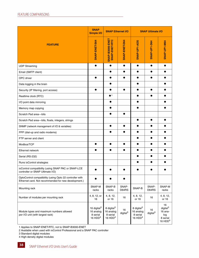
FEATURE COMPARISONS
SNAP Ethernet I/O Units User’s Guide38
UDP Streaming n n n n n n
Email (SMTP client) n n n n n
OPC driver n n n n n n
Data logging in the brain n n n
Security (IP filtering, port access) n n n n n n
Realtime clock (RTC) n1 n n n
I/O point data mirroring n n n
Memory map copying n n n
Scratch Pad area—bits n n
Scratch Pad area—bits, floats, integers, strings n n n
SNMP (network management of I/O & variables) n n n n n
PPP (dial-up and radio modems) n n n n n
FTP server and client n n n
Modbus/TCP n n n n n n
Ethernet network n n n n n n
Serial (RS-232) n n n
Runs ioControl strategies n n n
ioControl compatibility (using SNAP PAC or SNAP-LCE controller or SNAP Ultimate I/O)
n n n n n n
OptoControl compatibility (using Opto 22 controller with Ethernet card. Not recommended for new development.)
n n n
Mounting rackSNAP-M
racksSNAP-B
racksSNAP-D64RS
SNAP-BSNAP-D64RS
SNAP-M racks
Number of modules per mounting rack4, 8, 12, or
164, 8, 12,
or 1616
4, 8, 12, or 16
164, 8, 12,
or 16
Module types and maximum numbers allowed per I/O unit (with largest rack)
16 digital3
16 analog8 serial
16 HDD4
8 digital3
16 analog8 serial
16 HDD4
16 digital3
8 digital3
16 analog8 serial
16 HDD4
16 digital3
16 digital3
16 ana-log
8 serial16 HDD4
1 Applies to SNAP-ENET-RTC, not to SNAP-B3000-ENET2 Available when used with ioControl Professional and a SNAP PAC controller3 Standard digital modules4 High-density digital modules
FEATURE
SNAP Simple I/O
SNAP Ethernet I/O SNAP Ultimate I/O
SN
AP
-EN
ET-
S64
SN
AP
-B30
00-E
NE
TS
NA
P-E
NE
T-R
TC
SN
AP
-EN
ET-
D64
SN
AP
-UP
1-A
DS
SN
AP
-UP
1-D
64
SN
AP
-UP
1-M
64

CHAPTER 3: SYSTEM ARCHITECTURE
SNAP Ethernet I/O Units User’s Guide 3939
Additional Information on Features
Digital Point Features
For information on configuring digital point features, see the ioManager User’s Guide.
Latches—When the value of a digital input point changes from off to on, an on-latch is automatically set. While the value of the point may return to off, the on-latch remains set until cleared, as a record of the change. Similarly, an off-latch is set when the value of a digital point changes from on to off, and it remains set until cleared. Latching is automatic and needs no configuration.
Watchdogs—You can set a watchdog to monitor communication with the PC or other host device. If the host does not write data to the I/O unit for the length of time set in the watchdog, the I/O unit automatically sets designated digital and analog I/O points (but not points on high-density digital modules) to the values you have determined. This action makes sure the process is brought to a safe state if communication fails.
High-speed counters (Some brains only; see chart on page 37.)—Any standard or high-density digital input can be used as a counter, counting the number of times the input changes from off to on. High-density digital points always act as counters without needing configuration. Standard digital points must be configured as counters; as soon as it is configured, the counter is automatically activated.
Quadrature counters (Some brains only; see chart on page 37.)—When you configure points on a quadrature input module, the quadrature counter feature is automatically included. You can read the quadrature count from either point by reading the point’s counter data.
Additional digital features—The following digital features are available on some brains (see chart on page 37) but only when the brain is used with a SNAP PAC controller and ioControl Professional. These features are not currently available through ioManager or the memory map. Use ioControl commands to configure and access them. See the ioControl User’s Guide for more information.
• On-pulse and off-pulse measurement—A pulse is a brief on (or off ) state, usually repeated at a specific interval. The brain can measure the first pulse, that is, the amount of time the input stays on (or stays off ).
• TPO (time-proportional output)—Time-proportional output varies the duty cycle and the percentage of on time within that cycle. TPO is often combined with a PID loop and used to control the output, for example in a heater or oven.
• Pulse generation—Includes continuous square waves, on-pulses, off-pulses, and N pulses. A pulse turns a digital output on (or off ) briefly, either once or for a specified number of times at a specified interval. A digital square wave is a specific pattern of on and off states, repeated continuously.
Analog Point Features
These features apply to some brains only; see chart on page 37. For information on configuring analog features, see the ioManager User’s Guide.
UIOEIOSIO
UIOEIO
UIOEIO
UIOEIO
UIOEIOSIO
FEATURE COMPARISONS
SNAP Ethernet I/O Units User’s Guide40
Watchdogs—You can set a watchdog to monitor communication with the PC or other host device. If the host does not write data to the I/O unit for the length of time set in the watchdog, the I/O unit automatically sets designated I/O points to the values you have determined. This action makes sure the process is brought to a safe state if communication fails.
Scaling—You can scale analog input or output points so that the values make sense for your situation. For example, you can scale a -5 V to +5 V input point to show 0% to 100%.
Minimum and maximum values—The I/O unit automatically keeps track of minimum and maximum values. You can read these values at any time, for example, to record minimum and maximum temperatures. You can also reset min/max values. For example, if you want to record the maximum temperature at point 2 in each 24-hour period, you must reset the values after they are read each day.
Offset and gain—The brain can calculate offset and gain for analog input points. If a -50 mV to +50 mV input receives signals that are slightly off (not exactly -50 mV at the lowest point, for example), the offset and gain can be calculated so that values will appear accurately when read.
NOTE: If you are using Modbus/TCP, you will need to calculate the offset and gain yourself. Then you can write offset and gain values to the brain.
Output clamping—The I/O unit can clamp values sent to analog output points so they do not go above or below a specific limit. For example, if you are using a 0–10 VDC output module, but the device attached to one of its points can only handle a maximum of 5 VDC, you can set an upper clamp of 5 VDC for that point. The values for upper and lower clamp are set in engineering units.
Average filter weight—The I/O unit can use a filter weight to smooth analog input signals that are erratic or change suddenly. See details in the ioManager User’s Guide.
Ramping—Some devices attached to analog outputs should not be abruptly stepped up or down, because a sudden change might damage the equipment or cause other problems. Instead, you can gradually ramp the device up or down to the desired value. IMPORTANT: Ramping is available on some brains (see chart on page 37) but only when used with a SNAP PAC controller and ioControl Professional. Ramping is not currently available through ioManager or the memory map. Use ioControl commands to ramp an analog output. See the ioControl User’s Guide for more information.
Serial Communication
These features vary by brain model; see chart on page 37.
Serial communication generally occurs through SNAP serial communication modules. Most serial modules provide two channels of serial data, typically used to interface with printers, scales, chart recorders, barcode readers, or Wiegand® security devices. A Profibus module provides one channel of data from Profibus DP devices.
SNAP Simple I/O provides tunneling capability only, sending and receiving data from serial devices attached to the module. SNAP Ethernet and SNAP Ultimate I/O also provide full serial events. (See “Events, Timers, Event Messages, Email, Data Logging, Data Mirroring, and Memory Map Copying” on page 41 for more information.)
In addition, SNAP Ultimate brains can communicate directly to a serial device using the RS-232 connector on top of the brain. Communication is handled through ioControl commands. See “Communication Commands” in Chapter 10 of the ioControl User’s Guide.
UIOEIOSIO
CHAPTER 3: SYSTEM ARCHITECTURE
SNAP Ethernet I/O Units User’s Guide 4141
PID Loops
These features apply to some brains only; see chart on page 37.
Proportional integral derivative (PID) loops are used to drive a variable, often from an analog input, toward a desired value. The PID monitors the variable, compares it to the setpoint (the desired value) and calculates an output that will push the variable very close to the setpoint. Temperature control is a typical application for a PID.
Each SNAP Ultimate brain can run up to 32 PID loops; each SNAP Ethernet brain can run up to 16 PID loops. To use PID loops, configure them in ioControl or ioManager, and use ioControl tuning tools for ease in debugging. See Opto 22 form #1300, the ioControl User’s Guide, for more information.
NOTE: PID capabilities in SNAP Ethernet I/O units are compatible with ioControl, but not with OptoControl.
Events, Timers, Event Messages, Email, Data Logging, Data Mirroring, and Memory Map Copying
These features apply to some brains only; see chart on page 37. They do not apply to high-density digital modules.
A SNAP Ultimate or SNAP Ethernet I/O unit can be configured to recognize one or a combination of the following as an event:
• The state of a standard digital point (on or off )
• A specific high or low value of an analog point, in Engineering Units
• A specific number on a digital counter or a high or low number on a quadrature counter
• An analog point value or a quadrature counter that is outside an allowable range
• The state of a bit in the Scratch Pad (on or off )
• A specific string received by a serial module.
The brain can react automatically to an event in any or all of the following ways:
• Turning standard digital points on or off (on the same or a different brain)
• Copying data from one memory map location to another on the same or a different brain
• Logging data
• Turning a bit in the Scratch Pad on or off
• Sending a stream packet
• Sending an email message
• Sending a string through a serial module to a serial device
• Sending an SNMP trap.
In addition, you can use a timer to set up a delay between when the event occurs and the reaction takes place.
For more information on configuring and using events and reactions, see the ioManager User’s Guide.
UIOEIO
UIOEIO

FEATURE COMPARISONS
SNAP Ethernet I/O Units User’s Guide42
UDP Streaming
Most communication involves the two-step process of request and response. A faster way of getting information from an Ethernet-based I/O unit, however, is by streaming data. Streaming does not use TCP; it uses the User Datagram Protocol (UDP) instead. The I/O unit sends data at regular intervals to specified IP addresses. The communication is one-way; the I/O unit does not wait for a response.
You will need to write your own application in order to receive streamed data from the I/O unit. For more information on streaming, see Opto 22 form #1465, the OptoMMP Protocol Guide.
Security
You can use ioManager to limit access to Ethernet-based I/O units, either by allowing access only from specific computers or other devices on the network (IP filtering), or by limiting access to specific protocols, such as SNMP, that are used with the I/O unit (port access). See the ioManager User’s Guide for more information on security.
Scratch Pad Areas
SNAP Simple I/O brains do not have Scratch Pad areas.
SNAP Ethernet brains have Scratch Pad bits only; they are used primarily for event/reactions. See the ioManager User’s Guide for more information.
SNAP Ultimate brains have Scratch Pad bits, integers, floats, and strings. These Scratch Pad areas are used primarily for peer-to-peer communication with other SNAP Ultimate I/O units and SNAP controllers on the network. See the ioControl User’s Guide for more information.
SNMP
The Simple Network Management Protocol (SNMP) is used to communicate with an SNMP-based enterprise management system, such as Computer Associates’ Unicenter, Hewlett-Packard’s OpenView, or IBM’s Tivoli. These enterprise management systems can manage analog, digital, or serial devices through a SNAP Ultimate or SNAP Ethernet I/O system just as they manage computer equipment on the Ethernet network.
See the ioManager User’s Guide to configure the SNMP agent, establish community groups and management hosts, and set up SNMP traps.
PPP
Point-to-point protocol (PPP) is used to communicate to a SNAP Ethernet or SNAP Ultimate I/O unit through a modem. If you have these I/O units installed at remote locations or in other places where an Ethernet network is not available, you can set up communication so that the I/O unit can dial in to a PC, so that PCs can dial into the I/O unit, or both. See “Using PPP Over a Modem” on page 12 for more information.
FTP Server/Client
(SNAP Ultimate brains with firmware versions 5.0 or newer) These brains have a substantial area available for file storage, and data can be easily moved to and from these files using FTP. For more information on the file system, see the ioManager User’s Guide.
UIOEIOSIO
UIOEIOSIO
UIOEIO
UIOEIO
UIOEIO
UIO
SNAP Ethernet I/O Units User’s Guide 4343
Chapter 4
Maintaining the Ethernet-Based I/O Unit
IntroductionThis chapter includes step-by-step procedures for maintaining SNAP Ethernet-based I/O units, including:
Backup Battery
The SNAP-ENET-RTC brain has a replaceable backup battery, Opto 22 part number RTCBATT. This part can be ordered from our Web site, www.opto22.com.
The backup batteries in SNAP Ultimate brains are not user-replaceable. Their expected lifetime is 6–10 years of backup with power off.
Changing or Viewing the IP AddressEach SNAP Ethernet-based I/O unit must be assigned an appropriate IP address and subnet mask for your network. See the ioManager User’s Guide for more information about IP addresses and instructions to assign them.
If you need to change an IP address or subnet mask, or if you don’t know an I/O unit’s IP address and need to view it, you can do so using ioManager.
• Changing IP addresses See below
• Viewing IP addresses See page 48
• Resetting the brain to factory defaults See page 50
• Loading new firmware See page 51
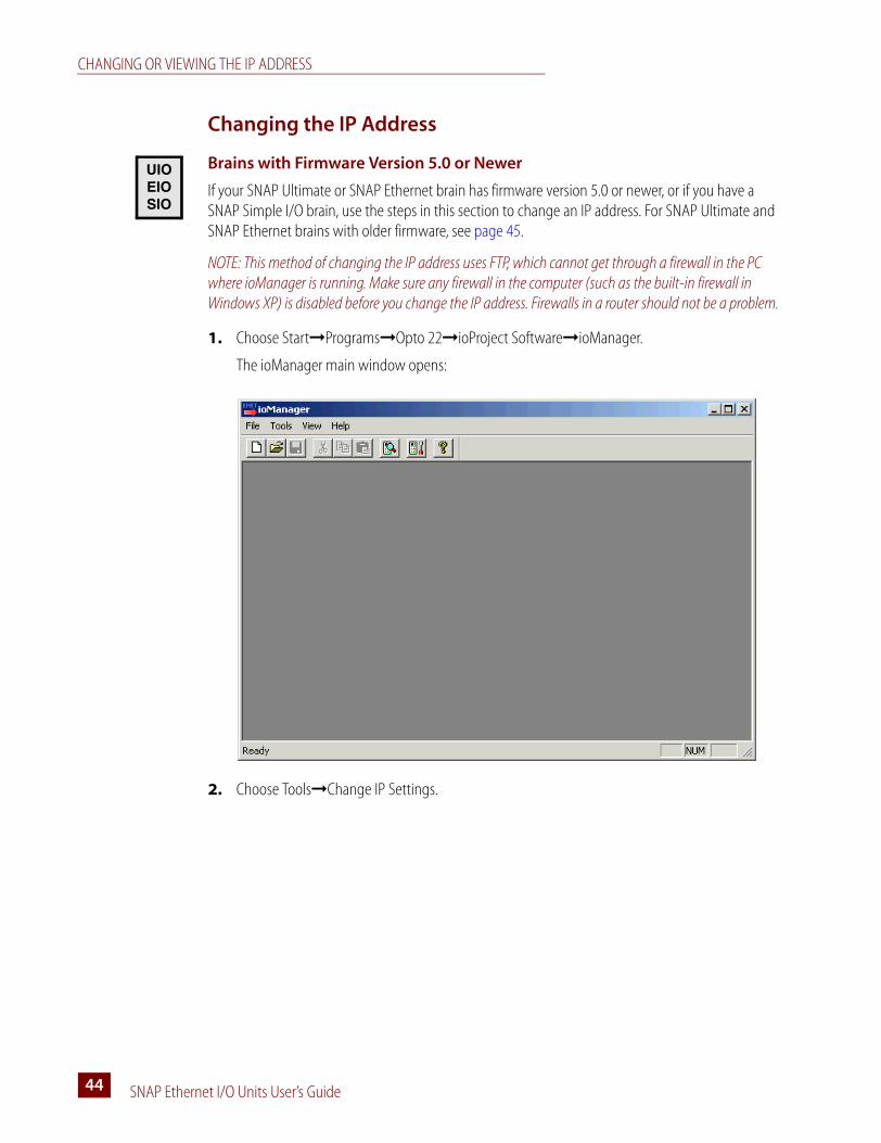
CHANGING OR VIEWING THE IP ADDRESS
SNAP Ethernet I/O Units User’s Guide44
Changing the IP Address
Brains with Firmware Version 5.0 or Newer
If your SNAP Ultimate or SNAP Ethernet brain has firmware version 5.0 or newer, or if you have a SNAP Simple I/O brain, use the steps in this section to change an IP address. For SNAP Ultimate and SNAP Ethernet brains with older firmware, see page 45.
NOTE: This method of changing the IP address uses FTP, which cannot get through a firewall in the PC where ioManager is running. Make sure any firewall in the computer (such as the built-in firewall in Windows XP) is disabled before you change the IP address. Firewalls in a router should not be a problem.
1. Choose Start➞Programs➞Opto 22➞ioProject Software➞ioManager.
The ioManager main window opens:
2. Choose Tools➞Change IP Settings.
UIOEIOSIO

CHAPTER 4: MAINTAINING THE ETHERNET-BASED I/O UNIT
SNAP Ethernet I/O Units User’s Guide 4545
3. In the Current IP Address field, type the IP address of the device whose address you want to view or change. Click Read Current Settings to see the current subnet mask, gateway address, and DNS address.
4. If you want to change the IP address, subnet mask, or other addresses, enter the new numbers. Make sure you have typed everything correctly. When everything is correct, click Change IP Settings.
After you confirm the change, a message appears stating that the change was successful and that the device will restart. Restarting may take 10 to 20 seconds to complete. When you see the following indicator, the device is ready for use with its new address:
the brain’s STD LED blinks twiceRemember to write the IP address on the sticker on the device.
Brains with Older Firmware
To change the IP address of a brain with firmware older than version 5.0, follow these steps.
1. In the ioManager main window, click the Inspect button .
2. In the IP Address field, type the IP address of the I/O unit. Click Status Write.
3. In the Operation Command list, highlight Switch to Loader Mode.
UIOEIO
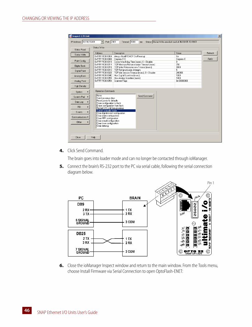
CHANGING OR VIEWING THE IP ADDRESS
SNAP Ethernet I/O Units User’s Guide46
4. Click Send Command.
The brain goes into loader mode and can no longer be contacted through ioManager.
5. Connect the brain’s RS-232 port to the PC via serial cable, following the serial connection diagram below.
6. Close the ioManager Inspect window and return to the main window. From the Tools menu, choose Install Firmware via Serial Connection to open OptoFlash-ENET:
Pin 1
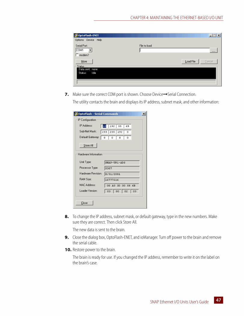
CHAPTER 4: MAINTAINING THE ETHERNET-BASED I/O UNIT
SNAP Ethernet I/O Units User’s Guide 4747
7. Make sure the correct COM port is shown. Choose Device➞Serial Connection.
The utility contacts the brain and displays its IP address, subnet mask, and other information:
8. To change the IP address, subnet mask, or default gateway, type in the new numbers. Make sure they are correct. Then click Store All.
The new data is sent to the brain.
9. Close the dialog box, OptoFlash-ENET, and ioManager. Turn off power to the brain and remove the serial cable.
10. Restore power to the brain.
The brain is ready for use. If you changed the IP address, remember to write it on the label on the brain’s case.
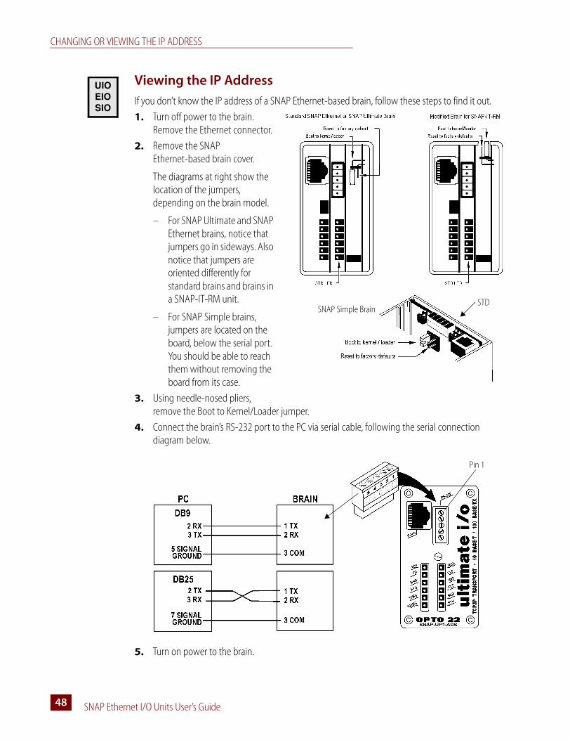
CHANGING OR VIEWING THE IP ADDRESS
SNAP Ethernet I/O Units User’s Guide48
Viewing the IP Address
If you don’t know the IP address of a SNAP Ethernet-based brain, follow these steps to find it out.
1. Turn off power to the brain. Remove the Ethernet connector.
2. Remove the SNAP Ethernet-based brain cover.
The diagrams at right show the location of the jumpers, depending on the brain model.
– For SNAP Ultimate and SNAP Ethernet brains, notice that jumpers go in sideways. Also notice that jumpers are oriented differently for standard brains and brains in a SNAP-IT-RM unit.
– For SNAP Simple brains, jumpers are located on the board, below the serial port. You should be able to reach them without removing the board from its case.
3. Using needle-nosed pliers, remove the Boot to Kernel/Loader jumper.
4. Connect the brain’s RS-232 port to the PC via serial cable, following the serial connection diagram below.
5. Turn on power to the brain.
UIOEIOSIO
SNAP Simple BrainSTD
Pin 1
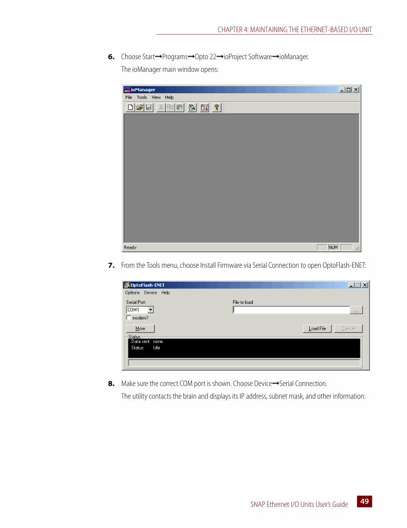
CHAPTER 4: MAINTAINING THE ETHERNET-BASED I/O UNIT
SNAP Ethernet I/O Units User’s Guide 4949
6. Choose Start➞Programs➞Opto 22➞ioProject Software➞ioManager.
The ioManager main window opens:
7. From the Tools menu, choose Install Firmware via Serial Connection to open OptoFlash-ENET:
8. Make sure the correct COM port is shown. Choose Device➞Serial Connection.
The utility contacts the brain and displays its IP address, subnet mask, and other information:
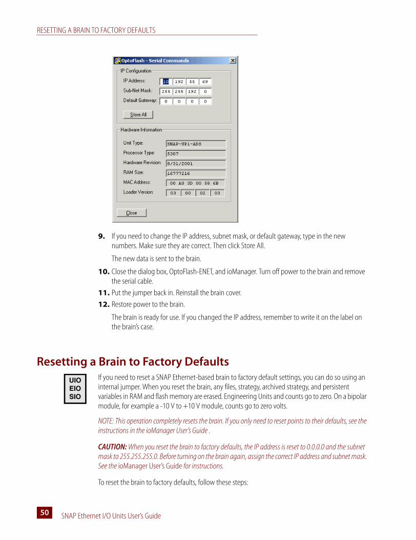
RESETTING A BRAIN TO FACTORY DEFAULTS
SNAP Ethernet I/O Units User’s Guide50
9. If you need to change the IP address, subnet mask, or default gateway, type in the new numbers. Make sure they are correct. Then click Store All.
The new data is sent to the brain.
10. Close the dialog box, OptoFlash-ENET, and ioManager. Turn off power to the brain and remove the serial cable.
11. Put the jumper back in. Reinstall the brain cover.
12. Restore power to the brain.
The brain is ready for use. If you changed the IP address, remember to write it on the label on the brain’s case.
Resetting a Brain to Factory DefaultsIf you need to reset a SNAP Ethernet-based brain to factory default settings, you can do so using an internal jumper. When you reset the brain, any files, strategy, archived strategy, and persistent variables in RAM and flash memory are erased. Engineering Units and counts go to zero. On a bipolar module, for example a -10 V to +10 V module, counts go to zero volts.
NOTE: This operation completely resets the brain. If you only need to reset points to their defaults, see the instructions in the ioManager User’s Guide .
CAUTION: When you reset the brain to factory defaults, the IP address is reset to 0.0.0.0 and the subnet mask to 255.255.255.0. Before turning on the brain again, assign the correct IP address and subnet mask. See the ioManager User’s Guide for instructions.
To reset the brain to factory defaults, follow these steps:
UIOEIOSIO

CHAPTER 4: MAINTAINING THE ETHERNET-BASED I/O UNIT
SNAP Ethernet I/O Units User’s Guide 5151
1. Turn off power to the brain. Remove the Ethernet connector.
2. Remove the SNAP Ethernet-based brain cover.
The diagrams at right show the location of the jumpers, depending on the brain model. The diagrams show the brain as it comes from the factory and should be for normal operation.
– For SNAP Ultimate and SNAP Ethernet brains, notice that jumpers go in sideways. Also notice that jumpers are oriented differently for standard brains and brains in a SNAP-IT-RM unit.
– For SNAP Simple brains, jumpers are located on the board, below the serial port. You should be able to reach them without removing the board from its case.
3. Using needle-nosed pliers, remove the Boot to Kernel/Loader jumper and put the Reset to Factory Defaults jumper in. Turn on power to the brain.
4. Watch the STD LED (shown in the graphic above). Wait until the solid light goes off, and then turn off power to the brain.
For more information on LEDs and blink codes, see page 61.
5. Remove the Reset to Factory Defaults jumper and insert the Boot to Kernel/Loader jumper, so the jumpers look like the figure again.
6. Reinstall the brain cover.
The brain has now been reset to factory defaults. To assign a new IP address, follow the steps in the ioManager User’s Guide. When you restore power to the brain, it begins sending BootP requests immediately.
Loading New FirmwareEach SNAP Ethernet-based brain and each SNAP serial communication module contains firmware (sometimes referred to as the kernel), which is similar to an operating system. If the firmware should become damaged, or if a new version of the firmware is released, you can load new firmware to the device using ioManager.
SNAP Simple BrainSTD

LOADING NEW FIRMWARE
SNAP Ethernet I/O Units User’s Guide52
NOTE: To load new firmware to a SNAP serial communication module, see Opto 22 form #1440, the ioManager User’s Guide, for instructions. These instructions require brain firmware version 5.0 or newer. If the brain’s firmware is older than version 5.0, update brain firmware using the steps on page 54 and then update serial module firmware.
Loading SNAP Ultimate Brain Firmware
These instructions apply to SNAP Ultimate brains that already have firmware version 5.0 or newer.
If your SNAP Ultimate brain has firmware older than version 5.0, or if you have a SNAP Ethernet or SNAP Simple I/O brain, see the section “Loading Brain Firmware (All Other Brains)” on page 54.
1. Make sure you have the following before beginning:
– New firmware from our Web site at www.opto22.com. If you have any difficulty obtaining or loading new firmware, contact Opto 22 Product Support.
– IP address(es) of the brain(s) that will receive the new firmware.
2. Choose Start➞Programs➞Opto 22➞ioProject Software➞ioManager.
The ioManager main window opens:
3. Click the Maintenance button .
UIO

CHAPTER 4: MAINTAINING THE ETHERNET-BASED I/O UNIT
SNAP Ethernet I/O Units User’s Guide 5353
4. Make sure Install Firmware is highlighted in the Command list.
5. Click the browse button and locate the firmware file you downloaded from our Web site.
Double-click the filename.
SNAP Ultimate brain firmware files have a file extension of .uio.
The path and filename appear in the Filename field.
6. If the IP address(es) of the SNAP devices you want to load firmware to appear in the IP Addresses list, skip to step 8. (Or, if you have previously saved a list of IP addresses, click Load to load the saved list.) If the address(es) you need don’t appear in the list, click Add.
7. Enter the address or a range of consecutive addresses, then click OK. (Or, if you are communicating with the device using its host name instead of its IP address, click Host Name and enter the name.)
The address(es) you entered appear in the I/O Unit Maintenance dialog box.
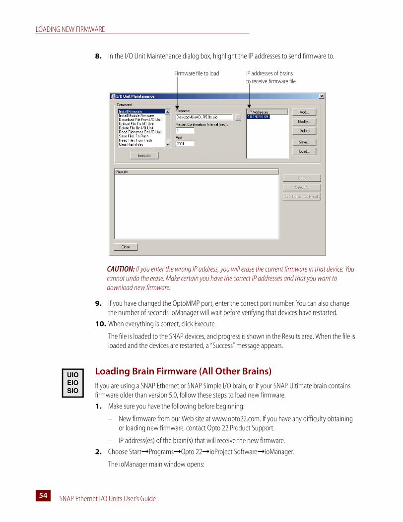
LOADING NEW FIRMWARE
SNAP Ethernet I/O Units User’s Guide54
8. In the I/O Unit Maintenance dialog box, highlight the IP addresses to send firmware to.
CAUTION: If you enter the wrong IP address, you will erase the current firmware in that device. You cannot undo the erase. Make certain you have the correct IP addresses and that you want to download new firmware.
9. If you have changed the OptoMMP port, enter the correct port number. You can also change the number of seconds ioManager will wait before verifying that devices have restarted.
10. When everything is correct, click Execute.
The file is loaded to the SNAP devices, and progress is shown in the Results area. When the file is loaded and the devices are restarted, a “Success” message appears.
Loading Brain Firmware (All Other Brains)
If you are using a SNAP Ethernet or SNAP Simple I/O brain, or if your SNAP Ultimate brain contains firmware older than version 5.0, follow these steps to load new firmware.
1. Make sure you have the following before beginning:
– New firmware from our Web site at www.opto22.com. If you have any difficulty obtaining or loading new firmware, contact Opto 22 Product Support.
– IP address(es) of the brain(s) that will receive the new firmware.
2. Choose Start➞Programs➞Opto 22➞ioProject Software➞ioManager.
The ioManager main window opens:
Firmware file to load IP addresses of brains to receive firmware file
UIOEIOSIO
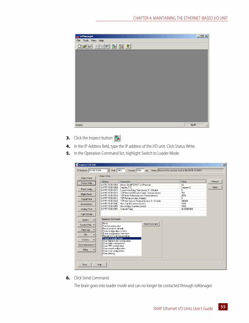
CHAPTER 4: MAINTAINING THE ETHERNET-BASED I/O UNIT
SNAP Ethernet I/O Units User’s Guide 5555
3. Click the Inspect button .
4. In the IP Address field, type the IP address of the I/O unit. Click Status Write.
5. In the Operation Command list, highlight Switch to Loader Mode.
6. Click Send Command.
The brain goes into loader mode and can no longer be contacted through ioManager.
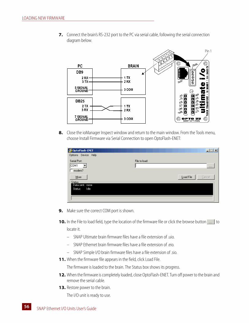
LOADING NEW FIRMWARE
SNAP Ethernet I/O Units User’s Guide56
7. Connect the brain’s RS-232 port to the PC via serial cable, following the serial connection diagram below.
8. Close the ioManager Inspect window and return to the main window. From the Tools menu, choose Install Firmware via Serial Connection to open OptoFlash-ENET:
9. Make sure the correct COM port is shown.
10. In the File to load field, type the location of the firmware file or click the browse button to
locate it.
– SNAP Ultimate brain firmware files have a file extension of .uio.
– SNAP Ethernet brain firmware files have a file extension of .eio.
– SNAP Simple I/O brain firmware files have a file extension of .sio.
11. When the firmware file appears in the field, click Load File.
The firmware is loaded to the brain. The Status box shows its progress.
12. When the firmware is completely loaded, close OptoFlash-ENET. Turn off power to the brain and remove the serial cable.
13. Restore power to the brain.
The I/O unit is ready to use.
Pin 1

SNAP Ethernet I/O Units User’s Guide 5757
Chapter 5
Troubleshooting
If you are having difficulty using SNAP Ethernet-based I/O units, here are some suggestions that may help. If you cannot find the answers you need in this book, contact Opto 22 Product Support. Contact information is on page 5.
Communicating with the I/O UnitIf you attempt to connect to the I/O unit using its IP address and you cannot, first check the following:
• Make sure the I/O unit has been turned on and the RUN or PWR LED is lit. (See “LED Descriptions” on page 35.)
• Make sure the brain is mounted on the correct rack (see the table on page 92).
• Make sure the brain’s hold-down screw has been tightened so that it is firmly attached to the rack.
• Verify that you typed in the correct address for the I/O unit. Check the label on the side of the brain, where the IP address should be written.
• Make sure the I/O unit has been assigned a valid IP address and subnet mask. SNAP Ethernet-based brains come from the factory with a default IP address of 0.0.0.0, which is invalid. The default subnet mask is 255.255.255.0. To assign IP address and subnet mask, see the ioManager User’s Guide.
• Make sure that no red LEDs on the brain are lit. A red LED could indicate a voltage supply problem. Each I/O unit should have its own power supply. The brain needs a minimum of 5.0 VDC, measured at the rack.
• Make sure you have up-to-date drivers installed on your computer’s Network Interface Card (NIC). Contact your system administrator or the manufacturer of the card for help.
• Make sure you have Administrator privileges on your computer and that any firewall in the computer (such as the built-in firewall in Windows XP) is temporarily disabled before you try to assign or change IP addresses, load firmware using ioManager’s Maintenance window, or work with files on the brain or controller. BootP and FTP cannot function through a firewall in the PC.
COMMUNICATING WITH THE I/O UNIT
SNAP Ethernet I/O Units User’s Guide58
Firewalls in a router are less likely to be a problem unless certain ports (such as FTP client) have been blocked, either by default or on purpose.
Pinging the I/O Unit
If you still cannot communicate with the I/O unit after you have checked these items, try to reach it using the PING protocol.
1. Choose Start➞Programs and open a command prompt.
2. At the prompt, type: ping [I/O unit’s IP address]
For example, type: ping 10.192.54.40
If the I/O unit responds, go to “Accessing the I/O Unit with ioManager” on page 58.
If the PING command cannot be found, choose Start➞Control Panel➞Network. Make sure TCP/IP is configured as a protocol and that an IP address and subnet mask are assigned.
If you see the message “Destination host route not defined,” the I/O unit probably has an inappropriate IP address and subnet mask. Make sure the IP address and subnet mask on the I/O unit are compatible with those on the computer. Follow the directions beginning on page 48 to check the IP address and subnet mask on the I/O unit, and change them if necessary.
If you see the message “No response from host,” check the following:
• Are the computer and I/O unit correctly connected? Is the I/O unit turned on?
• Are the IP address and subnet mask on the I/O unit compatible with those on the computer?
• Is the I/O unit in reset mode? (Check for a blinking STD light. STD blink codes are shown on page 61.)
If you still cannot ping the I/O unit, contact Opto 22 Product Support. (See page 5.)
Accessing the I/O Unit with ioManager
Once you know you can ping the I/O unit, try to access it using ioManager. You will need to know the I/O unit’s IP address.
1. If ioManager is not already open, choose Start➞Programs➞Opto 22➞ioProject Software➞ioManager.
The ioManager main window opens:

CHAPTER 5: TROUBLESHOOTING
SNAP Ethernet I/O Units User’s Guide 5959
2. In the ioManager main window, click the Inspect button .
3. In the IP Address field, type the IP address of the I/O unit (or choose it from the drop-down list). Click Status Read.
Information from the I/O unit is displayed in the window:
If information does not appear, contact Product Support. (See page 5.)
Date and time data was last read
Click to update data

COMMUNICATING WITH THE I/O UNIT
SNAP Ethernet I/O Units User’s Guide60
Solving Network Problems
If problems in communicating with the SNAP Ethernet-based I/O unit recur, check your network. The wires, switches, and so on in your Ethernet network are not part of the Opto 22 hardware, but any problems in your network may affect communication with Opto 22 products.
Create a Network Diagram
First, create a network diagram and verify the following:
• Cable connectors are firmly inserted.
• The switch has power. Switch LEDs indicate that the connection is up.
• Neither the PC nor the Ethernet-based I/O unitsuse the switch’s uplink port.
• The brain’s 10MB or 100MB LED is lit.
Check Ethernet Errors
Next, use ioManager to check Ethernet errors reported by the I/O unit. These errors indicate network problems. You will need to know the I/O unit’s IP address.
1. Choose Start➞Programs➞Opto 22➞ioProject Software➞ioManager.
2. In the ioManager main window, click the Inspect icon .
3. In the IP Address field, type the IP address of the I/O unit. Click Status Read.
4. Scroll down until you see the items Ethernet Errors: Late Collisions, Ethernet Errors: Excessive Collisions, and Ethernet Errors: Others.
Ethernet Errors
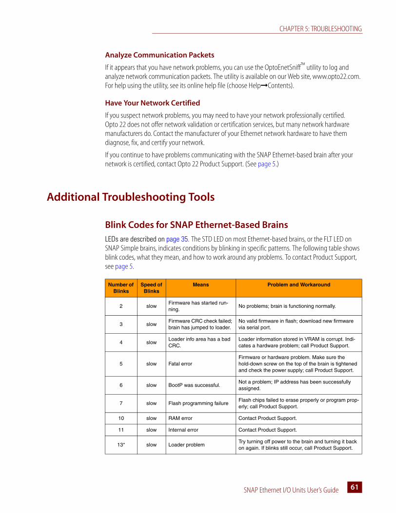
CHAPTER 5: TROUBLESHOOTING
SNAP Ethernet I/O Units User’s Guide 6161
Analyze Communication Packets
If it appears that you have network problems, you can use the OptoEnetSniff™ utility to log and analyze network communication packets. The utility is available on our Web site, www.opto22.com. For help using the utility, see its online help file (choose Help➞Contents).
Have Your Network Certified
If you suspect network problems, you may need to have your network professionally certified. Opto 22 does not offer network validation or certification services, but many network hardware manufacturers do. Contact the manufacturer of your Ethernet network hardware to have them diagnose, fix, and certify your network.
If you continue to have problems communicating with the SNAP Ethernet-based brain after your network is certified, contact Opto 22 Product Support. (See page 5.)
Additional Troubleshooting Tools
Blink Codes for SNAP Ethernet-Based Brains
LEDs are described on page 35. The STD LED on most Ethernet-based brains, or the FLT LED on SNAP Simple brains, indicates conditions by blinking in specific patterns. The following table shows blink codes, what they mean, and how to work around any problems. To contact Product Support, see page 5.
Number of Blinks
Speed of Blinks
Means Problem and Workaround
2 slowFirmware has started run-ning.
No problems; brain is functioning normally.
3 slowFirmware CRC check failed; brain has jumped to loader.
No valid firmware in flash; download new firmware via serial port.
4 slowLoader info area has a bad CRC.
Loader information stored in VRAM is corrupt. Indi-cates a hardware problem; call Product Support.
5 slow Fatal errorFirmware or hardware problem. Make sure the hold-down screw on the top of the brain is tightened and check the power supply; call Product Support.
6 slow BootP was successful.Not a problem; IP address has been successfully assigned.
7 slow Flash programming failureFlash chips failed to erase properly or program prop-erly; call Product Support.
10 slow RAM error Contact Product Support.
11 slow Internal error Contact Product Support.
13* slow Loader problemTry turning off power to the brain and turning it back on again. If blinks still occur, call Product Support.

ADDITIONAL TROUBLESHOOTING TOOLS
SNAP Ethernet I/O Units User’s Guide62
Determining Whether the I/O Unit is in Loader Mode
A SNAP Ethernet-based I/O unit can start up (boot) in one of two modes: kernel (firmware) or loader. Normal operation is to boot in kernel mode, meaning that the I/O unit boots to its firmware. For some operations, however (such as downloading new firmware), the I/O unit boots to loader mode, meaning that it starts up without firmware.
Kernel/loader mode can be changed using an internal jumper inside the brain’s case.
If you are having trouble communicating with the I/O unit and suspect it might be in loader mode, do one of the following to find out:
• Turn off power to the I/O unit , then turn it back on. Watch the STD LED. Three slow blinks means the I/O unit is in loader mode.
• Turn off power to the I/O unit , remove the brain’s top cover, and look at the Boot to Kernel/Loader jumper. See diagram on page 48. If the jumper is removed, the I/O unit is in loader mode.
• Try to ping the I/O unit. See steps on page 58. If the I/O unit is in loader mode, it will not respond. (There may be other reasons it does not respond, however; see the notes in “Pinging the I/O Unit.”)
If the I/O unit is in loader mode, replace the jumper if it was removed (see page 48 for diagram). If the I/O unit remains in loader mode, load new firmware (page 51).
TCP Settings
Retransmit timeout (RTO) refers to the length of time the I/O unit waits while communicating before timing out. The RTO is determined by the brain’s TCP/IP stack, and the stack continually recalculates the RTO based on recent network traffic. If the network becomes busier, for example, the stack automatically adjusts the RTO to a higher value.
If the TCP/IP stack times out while trying to transmit data, it doubles the current RTO and tries again. This process continues for five retries; after that, the SNAP brain stops trying and sends a timeout message.
14* slowBrain was reset to factory defaults.
Not a problem. Brain has been reset to factory defaults. IP address is now 0.0.0.0, so assign a new IP address. See the ioManager User’s Guide for instructions.
15 fast IP address was cleared.Not a problem. IP address is now 0.0.0.0. Assign a new IP address. See the ioManager User’s Guide for instructions.
* Does not apply to SNAP Ethernet brains.
Number of Blinks
Speed of Blinks
Means Problem and Workaround
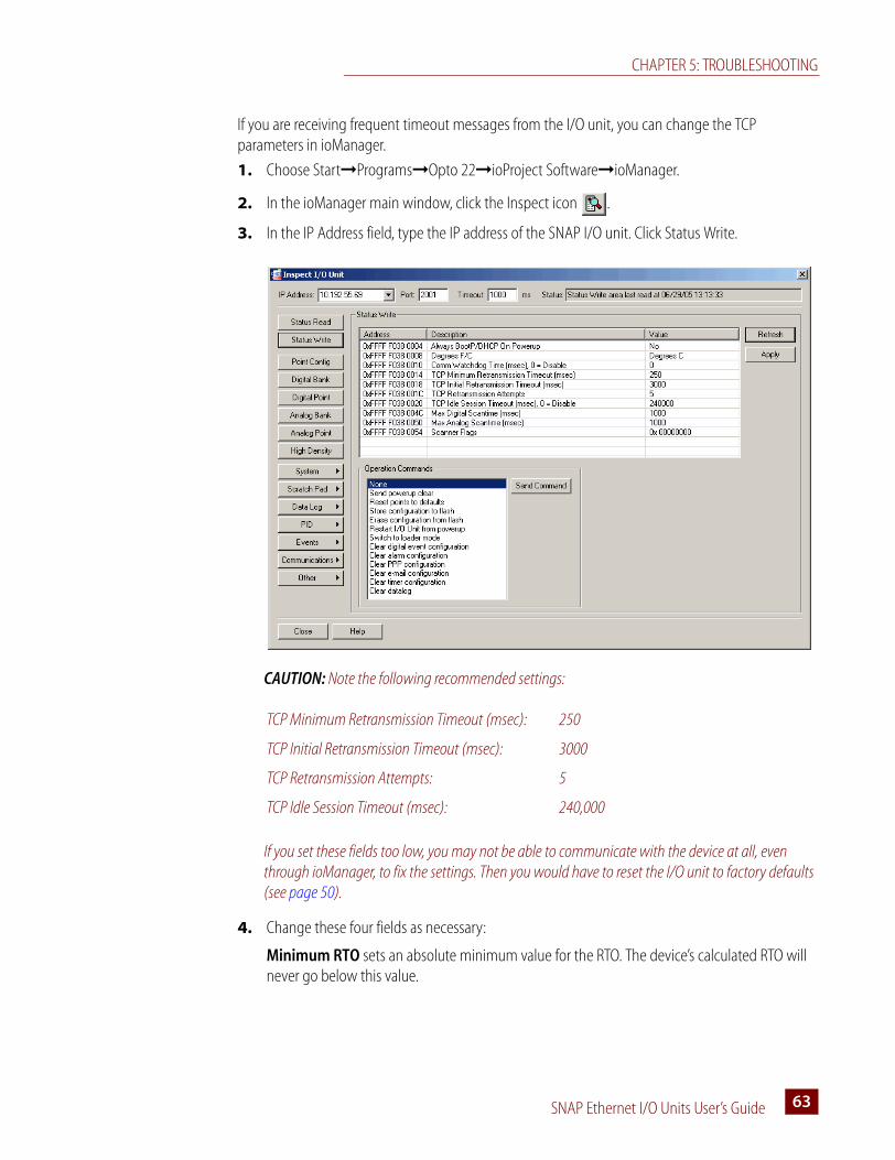
CHAPTER 5: TROUBLESHOOTING
SNAP Ethernet I/O Units User’s Guide 6363
If you are receiving frequent timeout messages from the I/O unit, you can change the TCP parameters in ioManager.
1. Choose Start➞Programs➞Opto 22➞ioProject Software➞ioManager.
2. In the ioManager main window, click the Inspect icon .
3. In the IP Address field, type the IP address of the SNAP I/O unit. Click Status Write.
CAUTION: Note the following recommended settings:
If you set these fields too low, you may not be able to communicate with the device at all, even through ioManager, to fix the settings. Then you would have to reset the I/O unit to factory defaults (see page 50).
4. Change these four fields as necessary:
Minimum RTO sets an absolute minimum value for the RTO. The device’s calculated RTO will never go below this value.
TCP Minimum Retransmission Timeout (msec): 250
TCP Initial Retransmission Timeout (msec): 3000
TCP Retransmission Attempts: 5
TCP Idle Session Timeout (msec): 240,000

ADDITIONAL TROUBLESHOOTING TOOLS
SNAP Ethernet I/O Units User’s Guide64
Initial RTO sets the RTO for the first communication try. Be careful: since all future tries are based on this value, if you set it too low for network conditions, a connection will never be made.
TCP Retransmits sets the number of times the device retries communication. Larger, busier networks need a higher number of retransmits than smaller networks with less traffic.
TCP idle session timeout sets how long (in milliseconds) the device allows a session to remain open without any activity. After this time, the device checks the session to make sure it is still good, and closes it if it is not. The default is 240,000 milliseconds, or four minutes.
5. Click the Apply button to write your changes to the SNAP I/O unit.
6. In the Operation Commands list, highlight Store configuration to flash. Click Send Command.
7. In the Operation Commands list, highlight Restart brain from powerup. Click Send Command.
The new TCP parameters are set.
Getting Device and Firmware Information
If you need to contact Opto 22 Product Support for assistance in using an I/O unit, it is helpful to have device and firmware information at hand before you call us.
1. Choose Start➞Programs➞Opto 22➞ioProject Software➞ioManager.
2. In the ioManager main window, click the Inspect button .
3. In the IP Address field, type the IP address of the device. Click Status Read.
The example shows a SNAP Ultimate I/O unit; other I/O units are similar.

CHAPTER 5: TROUBLESHOOTING
SNAP Ethernet I/O Units User’s Guide 6565
SNAP I/O Modules Troubleshooting
SNAP Digital Troubleshooting
Q: I have a SNAP digital module that has ceased to function. What may have caused this?
A: Loss of function in a SNAP digital module is normally caused by misapplication. As with Opto 22’s other digital I/O module families, there is no one way in which SNAP I/O modules fail. Output modules normally fail in a different way than inputs.
Output modules usually fail open, or half-wave for AC, and the failure is normally caused by the application of too much current or by degradation of the semiconductor switch by overvoltage.
Because the module is separated into two parts by the optical isolator, it is possible to have an output module that behaves properly on the logic side but is broken on the field side. The LED will in most cases continue to turn on and off as commanded by the driving logic device, even though the module has failed.
The first step to troubleshooting a failed module is to check the fuse. If it is blown, simply replacing it should get the module working again. If the module continues to blow fuses, analyze the load to see if the module is really suitable to the application.
When input modules fail, they usually do so on the field side, typically from overvoltage or overcurrent resulting from overvoltage. Opto 22’s SNAP AC and DC input modules contain a full-wave rectifier (as opposed to the G1 and G4 modules, which contain a bridge rectifier), allowing hookup without regard to polarity. Unlike output modules, an input module’s LED normally will not function as expected when the module has failed.
Failures on the field side of all types of Opto 22 digital I/O modules occur extremely rarely and are typically the result of misapplication. The logic-side failures of Opto 22’s I/O modules are also extremely rare. Usually, a failure of the logic side is attributable to using the module at the wrong logic voltage or to miswiring.
Q: I have an input module that seems to “flicker” when a voltage is applied to it. What is happening here?
A: Opto 22’s basic input modules contain full-wave rectifiers. In an AC application it is possible to destroy one-half of the rectifier and still have the module function after a fashion. The full-wave rectifier turns into a half-wave rectifier, causing the module to turn on and off at the line frequency when an input is applied. This may be seen visibly as “flicker” on the channel status LED.
Digital logic devices, having much faster detection times than the human eye, can have serious problems with this failure mode. For example, a digital counter attached to a failed module will count at the input frequency.
This failure occurs most commonly in applications where the input module is placed in parallel with an inductive load. When the load turns off, the back-EMF goes right through the module, destroying one-half of the bridge.
Placing a transorb or large R-C snubber in parallel with both the load and input module will significantly reduce the frequency of, or eliminate entirely, this type of failure.

SNAP I/O MODULES TROUBLESHOOTING
SNAP Ethernet I/O Units User’s Guide66
Q: I have an output module driving a load. The load turns on okay but never seems to turn off, unless I remove power from the relay entirely. What might be happening?
A: This problem may occur when using an output module with a high-impedance load, such as a neon lamp or a small solenoid. Loads like these often have relatively large initial currents but relatively small “hold-in” currents. The result is that the off-state leakage current through the module is insufficient to cause the load to turn on to start with, but sufficient to keep it on once started.
The solution to this problem is to place a power resistor, sized for 8–10 times the rated maximum leakage current for the module, in parallel with the load. Make sure that this resistor has a high enough power rating for the application.
Q: I have a new AC output driving a solenoid. It turns on okay once, but will not turn on again. What is going on?
A: Some solenoids and some types of halogen lights incorporate a diode in series with the coil or filament. This causes the light to behave as a half-wave rectifier. Opto 22 output modules have a built-in R-C snubber circuit in parallel with the output. The capacitor in this circuit charges up but cannot discharge through the series diode, causing a voltage to appear across the output terminals. Because the module must see a zero voltage across the terminals to come on, it can’t turn on again in this situation.
The solution is to find a lamp or solenoid that does not have an internal diode; a potential work-around would be to put a high-value resistor (several tens of KOhms) across the output terminals of the module, to allow the capacitor to drain its charge.
Q: I have an AC output module in a circuit, wired in series (ANDed) with another contact. When that other contact closes, my load turns on momentarily, even though my output module is off. Is my module broken?
A: This situation arises when the output module does not see a voltage across its terminals. This occurs when another contact is wired in series with the module, between the module and the “hot” side of the supply. Because the module is totally isolated from field to logic, the field (or contact) side of the module must power itself from the attached line. By nature of the pilot circuit in the module, the switching semiconductor is in an indeterminate state when there is no voltage across the module. It may turn on for up to a half cycle if it is suddenly “wet.” The pilot circuit will realize that the module is on, but it cannot turn it off until the voltage crosses zero again.
There is no easy solution to this problem. Typically a solution will involve either maintaining a minimal voltage across the module, pre-wetting it with a low voltage, or absorbing the energy from the half-cycle turn-on with an R-C network in parallel with the load.
Q: Why are all four loads connected to my SNAP output module coming on when I’m activating only one of the channels?
A: The SNAP digital output is likely connected on the wrong side of the loads. Remember that all four channels share one fuse; thus one side of each output is common with one side of all the others. If the module is on the wrong side of the load, any one channel is effectively connected to all four. If the output is a SNK type, try switching to a SRC type. In AC applications, reverse the module wiring.
CHAPTER 5: TROUBLESHOOTING
SNAP Ethernet I/O Units User’s Guide 6767
Q: I keep having failures on one channel of my SNAP output module. Why might this be happening?
A: Failures of only one of the four output channels would indicate a problem with the load being driven by that channel. Make sure that the load characteristics, including transient characteristics, do not exceed the capabilities of the module. Also be sure that the module is properly transient protected, using either an R-C snubber (AC) or a commutating diode (DC) across the load. Modules may also be protected through the use of transient voltage suppressors across the module itself.
SNAP Analog Troubleshooting
SNAP analog modules require a fairly substantial amount of current due to their on-board isolation power inverters. Because of this, it is important to make certain that the entire SNAP installation is supplied with 5.0 to 5.2 V, even while under full load.
See Opto 22 form #1403, SNAP I/O Wiring Guide, for help in determining the full load required for an I/O unit, which includes the brain or on-the-rack controller and all modules. Insufficient power supply could cause symptoms ranging from module “drift” to random resets and communication problems on the brain. The SNAP equipment is designed with a fail-safe voltage watchdog feature that inhibits operation when power supply voltage levels get too low, thus eliminating the possibility of unintentional output or input. Opto 22 offers DIN-rail-mountable power supplies for use with SNAP I/O systems.
Keep in mind that unless you purchase an isolated module, the channels on a SNAP input or output module are not isolated from one another. Make certain that any transducers or equipment that these modules are used with are floating, isolated from local earth ground. If the equipment is not floating, make certain that the two pieces of equipment being connected are at the same ground potential in order to eliminate the possibility of a ground loop through the module. A ground loop through the module could result in almost anything, from inaccurate readings to catastrophic failure of the module.
SNAP analog modules, like any high-level electronics, require protection from electrical noise in high-noise environments, such as installations near arc or plasma equipment or AC inverters. If the SNAP analog system is to be installed in such an environment, be certain that the system is enclosed in an appropriate enclosure. Opto 22 has several documents available that discuss grounding and shielding practice, noise mitigation, and electromagnetic compatibility:
• Grounding, Shielding, Noise, and Compatibility (Opto 22 form #TN9603)
• Grounding and Wiring Practices (form #TN9603A)
• Operational Interferences and Noise (form #TN9603B)
• Interference Generation and Compatibility (form #TN9603C)

SNAP I/O MODULES TROUBLESHOOTING
SNAP Ethernet I/O Units User’s Guide68

SNAP Ethernet I/O Units User’s Guide 6969
Appendix A
Using Modbus/TCP
This chapter includes instructions for using Modbus/TCP to communicate with SNAP Ethernet-based I/O units. Usually, Modbus/TCP is used simply to access I/O points in order to read and write point data. If necessary, however, it also can be used to access other areas of the brain’s memory map.
This chapter includes information on Modbus communication and working with SNAP I/O points, and it includes the Modbus memory map for the brain. If you need to use Modbus/TCP to access other areas of the memory map, see the Modbus chapter in Opto 22 form #1465, the OptoMMP Protocol Guide.
This chapter assumes that you already have an understanding of Modbus/TCP programming and communications. Use this chapter in conjunction with the Open Modbus/TCP Specification and the Modicon Modbus Protocol Reference Guide, both available from Modicon, Inc., Industrial Automation Systems.
Overview of Modbus CommunicationCommunicating with Ethernet-based I/O units using Modbus/TCP requires four basic steps: connect, configure, read/write, and disconnect. When opening a TCP/IP connection to the system, you normally use port 502.
Up to two Modbus masters can be simultaneously handled by the Ethernet-based I/O unit. Use a slave address (Unit ID) of 1 for the I/O unit.
Understanding Opto 22 and Modbus Differences
Notice that Opto 22 point numbers on the I/O unit commonly start numbering at 0 (zero), while Modbus coil or input numbers start at 1; so Modbus coil 1 or input 1 usually equals Opto 22 point 0. To reduce confusion, use the I/O reference diagrams starting on page 73, rather than using the diagrams shown in the ioManager User’s Guide.
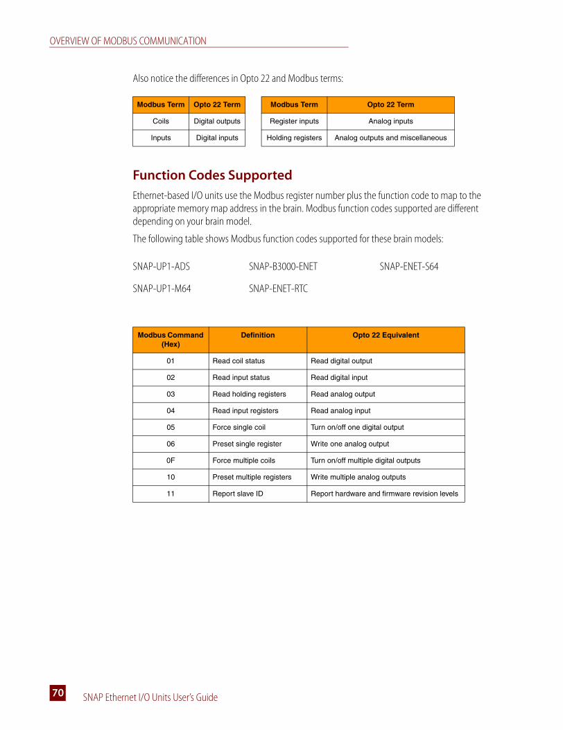
OVERVIEW OF MODBUS COMMUNICATION
SNAP Ethernet I/O Units User’s Guide70
Also notice the differences in Opto 22 and Modbus terms:
Function Codes Supported
Ethernet-based I/O units use the Modbus register number plus the function code to map to the appropriate memory map address in the brain. Modbus function codes supported are different depending on your brain model.
The following table shows Modbus function codes supported for these brain models:
Modbus Term Opto 22 Term Modbus Term Opto 22 Term
Coils Digital outputs Register inputs Analog inputs
Inputs Digital inputs Holding registers Analog outputs and miscellaneous
SNAP-UP1-ADS SNAP-B3000-ENET SNAP-ENET-S64
SNAP-UP1-M64 SNAP-ENET-RTC
Modbus Command (Hex)
Definition Opto 22 Equivalent
01 Read coil status Read digital output
02 Read input status Read digital input
03 Read holding registers Read analog output
04 Read input registers Read analog input
05 Force single coil Turn on/off one digital output
06 Preset single register Write one analog output
0F Force multiple coils Turn on/off multiple digital outputs
10 Preset multiple registers Write multiple analog outputs
11 Report slave ID Report hardware and firmware revision levels

APPENDIX A: USING MODBUS/TCP
SNAP Ethernet I/O Units User’s Guide 7171
The following table shows Modbus function codes supported for these digital-only brain models:
NOTE: Command 0x11, Report slave ID, returns data bytes as shown in the following table. Bytes 1 and 2 are always in the formats shown. The 0x22 in byte 1 indicates an Opto 22 brain; 0xFF appears in byte 2 because, since the brain is a slave, it is always running.
Communication Packet
As the Modbus/TCP specification requires, Ethernet-based I/O units use a Modbus packet inside TCP/IP. The Modbus checksum is not used; instead, the Ethernet TCP/IP link layer checksum guarantees data. The size of the packet is limited to 256 bytes. The packet follows the standard Modbus format and contains the following:
Note: You can read a maximum of 127 input or holding registers in one command 03 or 04.
SNAP-UP1-D64 SNAP-ENET-D64
Modbus Command (Hex)
Definition Opto 22 Equivalent
01 Read coil status Read digital input or output
05 Force single coil Turn on/off one digital output
0F Force multiple coils Turn on/off multiple digital outputs
11 Report slave ID Report hardware and firmware revision levels
Byte 1 Byte 2 Bytes 3–6 Bytes 7–10 Bytes 11–14
Slave ID
Run Indicator
Hardware Version Kernel Version Loader Version
Month Day Year Month Day Year Month Day Year
0x22 0xFF 0x01 0x01 0x01 0x01 0x01 0x01 0x01 0x01 0x01 0x01 0x01 0x01
Byte 0 Identifier, copied by responder (usually 0)
Byte 1 Identifier, copied by responder (usually 0)
Byte 2 Protocol identifier = 0
Byte 3 Protocol identifier = 0
Byte 4 Length field (upper byte) = 0, since all messages are smaller than 256
Byte 5 Length field (lower byte) = number of bytes following
Byte 6 Unit identifier (slave address, normally 1)
Byte 7 Modbus function code (See tables starting on page 70.)
Byte 8 and following Data as needed

OVERVIEW OF MODBUS COMMUNICATION
SNAP Ethernet I/O Units User’s Guide72
Exception Errors
If an error occurs, standard Modbus exception codes are returned in the Modbus packet. The following table, reprinted from the Modicon Modbus Protocol Reference Guide, shows the Modbus exception codes. If you need more information, see the Modicon documentation.
Code Name Meaning
01 ILLEGAL FUNCTIONThe function code received in the query is not an allowable action for the slave.
02 ILLEGAL DATA ADDRESSThe data address received in the query is not an allowable address for the slave.
03 ILLEGAL DATA VALUEA value contained in the query data field is not an allowable value for the slave.
04 SLAVE DEVICE FAILUREAn unrecoverable error occurred while the slave was attempting to perform the requested action.
05 ACKNOWLEDGE
The slave has accepted the request and is processing it, but a long duration of time will be required to do so. This response is returned to prevent a timeout error from occur-ring in the master. The master can next issue a Poll Program Complete message to deter-mine if processing is completed.
06 SLAVE DEVICE BUSY
The slave is engaged in processing a long-duration program command. The master should retransmit the message later when the slave is free.
07 NEGATIVE ACKNOWLEDGE
The slave cannot perform the program func-tion received in the query. This code is returned for an unsuccessful programming request using function code 13 or 14 decimal. The master should request diagnostic or error information from the slave.
08 MEMORY PARITY ERROR
The slave attempted to read extended mem-ory, but detected a parity error in the memory. The master can retry the request, but service may be required on the slave device.

APPENDIX A: USING MODBUS/TCP
SNAP Ethernet I/O Units User’s Guide 7373
SNAP I/O Referencing for ModbusI/O point referencing is slightly different depending on the brain model you have, since brains differ in the number and placement of I/O points they can control on the rack.
Modbus I/O Referencing for Most Analog/Digital Brains
The following diagram applies to these analog/digital brain models:
These brains are connected to SNAP B-series I/O mounting racks, which can hold either 4, 8, 12, or 16 Opto 22 SNAP I/O modules. Analog and high-density digital modules can be placed in any position on these racks. For the larger racks, standard digital modules can be placed in positions 0–7 only. For more information, see the data sheet for your rack. Data sheets can be downloaded from www.opto22.com.
Each standard SNAP digital module contains four input or four output channels. High-density digital modules contain 32 input or 32 output channels. SNAP analog modules supported by these brains with Modbus contain either two or four channels. If you are using two-channel analog modules, ignore the upper two channels.
CAUTION: Do NOT connect these brains to any other rack, as they are designed for use with B-series racks only. Using any other rack will severely damage the brain.
The following diagram shows Modbus referencing for digital and analog points.
SNAP-UP1-ADS
SNAP-ENET-RTC
SNAP-B3000-ENET
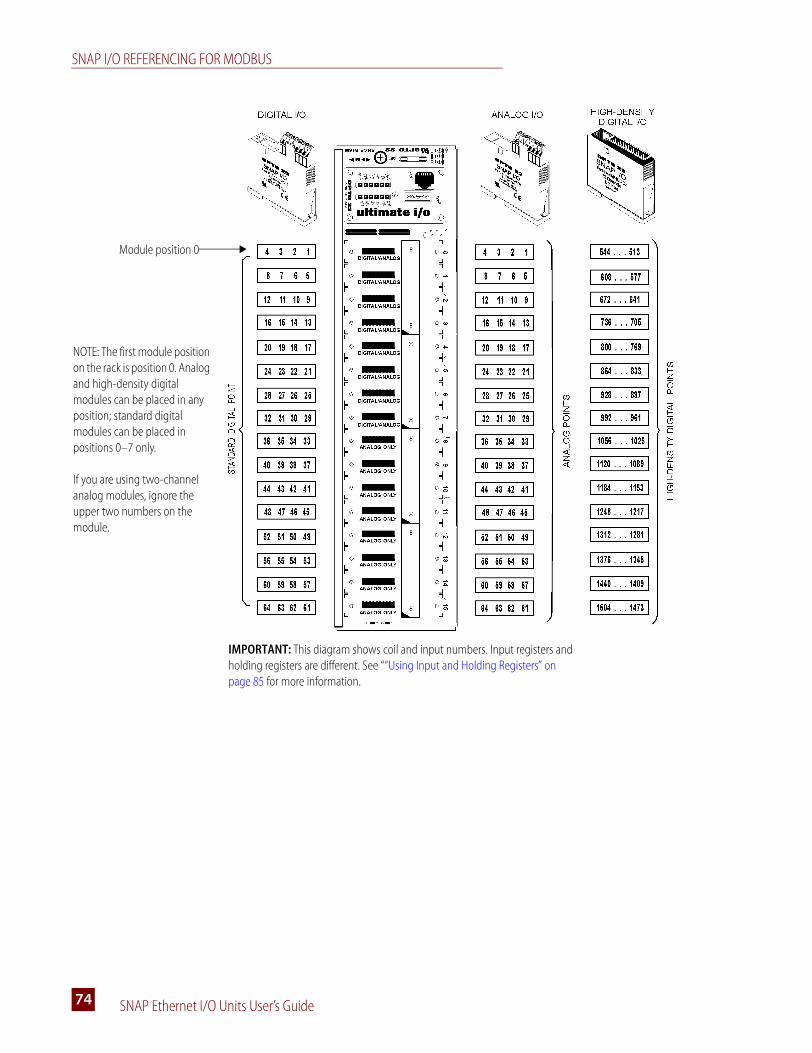
SNAP I/O REFERENCING FOR MODBUS
SNAP Ethernet I/O Units User’s Guide74
NOTE: The first module position on the rack is position 0. Analog and high-density digital modules can be placed in any position; standard digital modules can be placed in positions 0–7 only.
If you are using two-channel analog modules, ignore the upper two numbers on the module.
Module position 0
IMPORTANT: This diagram shows coil and input numbers. Input registers and holding registers are different. See ““Using Input and Holding Registers” on page 85 for more information.

APPENDIX A: USING MODBUS/TCP
SNAP Ethernet I/O Units User’s Guide 7575
Modbus I/O Referencing for Analog/Simple Digital Brains
The following diagram applies to these analog/simple digital brain models:
These brains are connected to a SNAP M-series mounting rack, which can hold up to 4, 8, or 16 Opto 22 SNAP I/O analog or digital modules (both standard and high-density) in any position on the rack.
Since each standard SNAP digital module contains four input or four output channels, the rack can hold a total of 64 points of standard digital I/O. It can hold a total of 512 points of high-density digital I/O. SNAP analog modules supported by the brain with Modbus contain either two or four channels. If you are using two-channel analog modules, ignore the upper two channels.
CAUTION: Do NOT connect these brains to any rack except the SNAP-M64. Using any other rack will severely damage the brain.
SNAP-UP1-M64 SNAP-ENET-S64
Module position 0
IMPORTANT: This diagram shows coil and input numbers. Input registers and holding registers are different. See “Using Input and Holding Registers” on page 85 for more information.
If you are using two-channel analog modules, ignore the upper two numbers on the module.
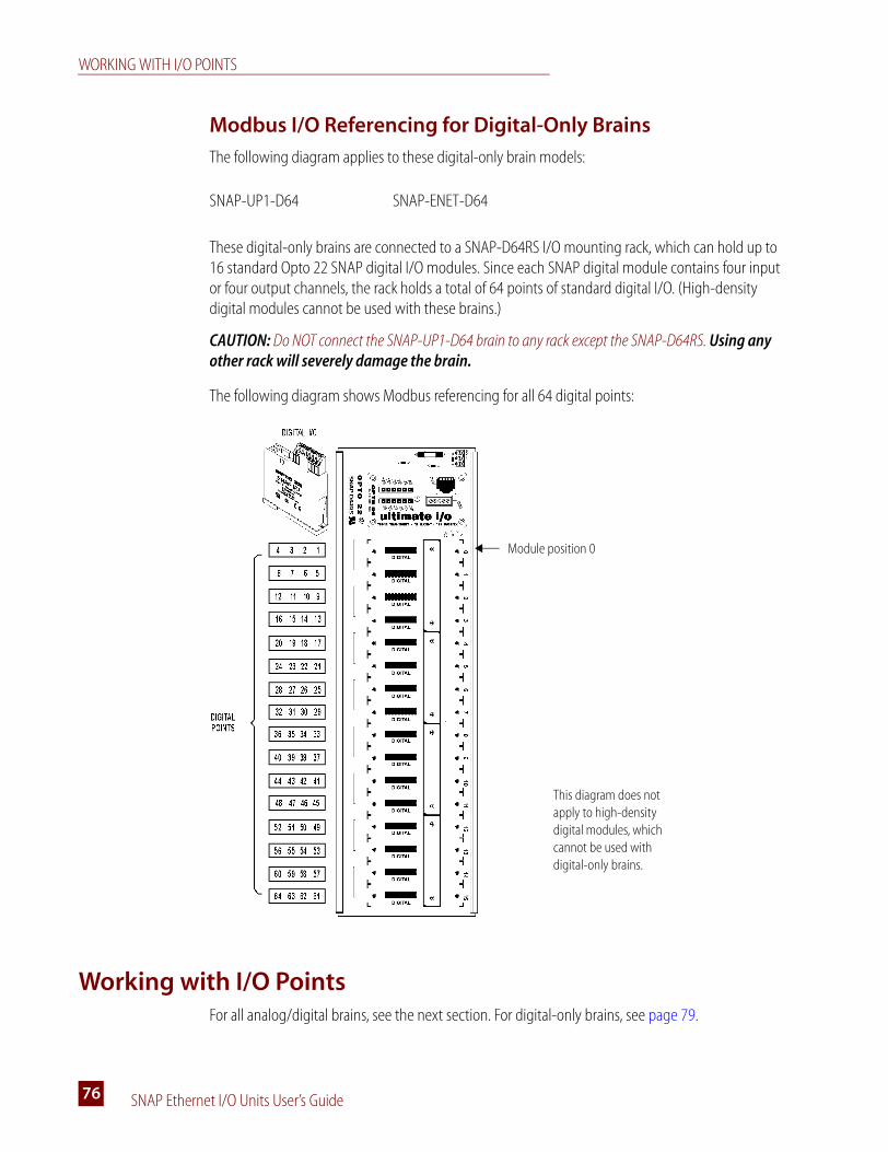
WORKING WITH I/O POINTS
SNAP Ethernet I/O Units User’s Guide76
Modbus I/O Referencing for Digital-Only Brains
The following diagram applies to these digital-only brain models:
These digital-only brains are connected to a SNAP-D64RS I/O mounting rack, which can hold up to 16 standard Opto 22 SNAP digital I/O modules. Since each SNAP digital module contains four input or four output channels, the rack holds a total of 64 points of standard digital I/O. (High-density digital modules cannot be used with these brains.)
CAUTION: Do NOT connect the SNAP-UP1-D64 brain to any rack except the SNAP-D64RS. Using any other rack will severely damage the brain.
The following diagram shows Modbus referencing for all 64 digital points:
Working with I/O PointsFor all analog/digital brains, see the next section. For digital-only brains, see page 79.
SNAP-UP1-D64 SNAP-ENET-D64
Module position 0
This diagram does not apply to high-density digital modules, which cannot be used with digital-only brains.

APPENDIX A: USING MODBUS/TCP
SNAP Ethernet I/O Units User’s Guide 7777
Configuring I/O Points for Analog/Digital Brains
All analog/digital brains recognize analog and special-purpose modules on the rack, but the brains do not recognize individual analog point values. Positions on the rack that don’t contain analog or special-purpose modules are assumed to contain standard digital input modules. If the actual point types differ from the defaults, you must configure the points using the table below.
NOTE: High-density digital modules do not require configuration.
I/O Point Types
The following table shows I/O point types that can be used with Ethernet-based I/O units and Modbus/TCP. Default types are shaded. If a point differs from the default, use the values in the table to configure the point. For examples of point configuration, see page 79, following the table.
Point Type SNAP Module Part Number
Value(Hex)
Standard Digital Points
Standard Digital Input All standard SNAP digital input modules 100
Standard Digital Output All standard SNAP digital output modules 180
Analog Input Points
0 to 20 mA InputSNAP-AIMA, SNAP-AIMA-i, SNAP-AIMA-iSRC, SNAP-AIMA-4
02
4 to 20 mA InputSNAP-AIMA, SNAP-AIMA-i, SNAP-AIMA-iSRC, SNAP-AIMA-4
03
-20 mA to +20 mA InputSNAP-AIMA, SNAP-AIMA-i, SNAP-AIMA-iSRC, SNAP-AIMA-4
40
-1 to +1 mA Input SNAP-AIMA2-i 55
0 to 10 Amps RMS Input SNAP-AIARMS, SNAP-AIPM (point 2 only) 47
-25 mV to +25 mV Input SNAP-AITM2, SNAP-AITM2-i, SNAP-AIMV2-4 43
-50 mV to +50 mV Input SNAP-AITM2, SNAP-AITM2-i, SNAP-AIMV2-4 09
-75 mV to +75 mV Input SNAP-AITM, SNAP-AITM-i, SNAP-AIMV-4 44
-150 mV to +150 mV Input SNAP-AITM, SNAP-AITM-i, SNAP-AIMV-4 42
0 to 5 V Input SNAP-AIV, SNAP-AIV-i, SNAP-AIV-4 06
0 to 10 V Input SNAP-AIV, SNAP-AIV-i, SNAP-AIV-4 07
-5 V to +5 V Input SNAP-AIV, SNAP-AIV-i, SNAP-AIV-4 0B
-10 V to +10 V Input SNAP-AIV, SNAP-AIV-i, SNAP-AIV-4 0C
-100 to +100 VDC Input SNAP-AIV2-i 48
-50 to +50 VDC Input SNAP-AIV2-i 49
0 to 250 V RMS Input SNAP-AIVRMS, SNAP-AIPM (point 1 only) 46
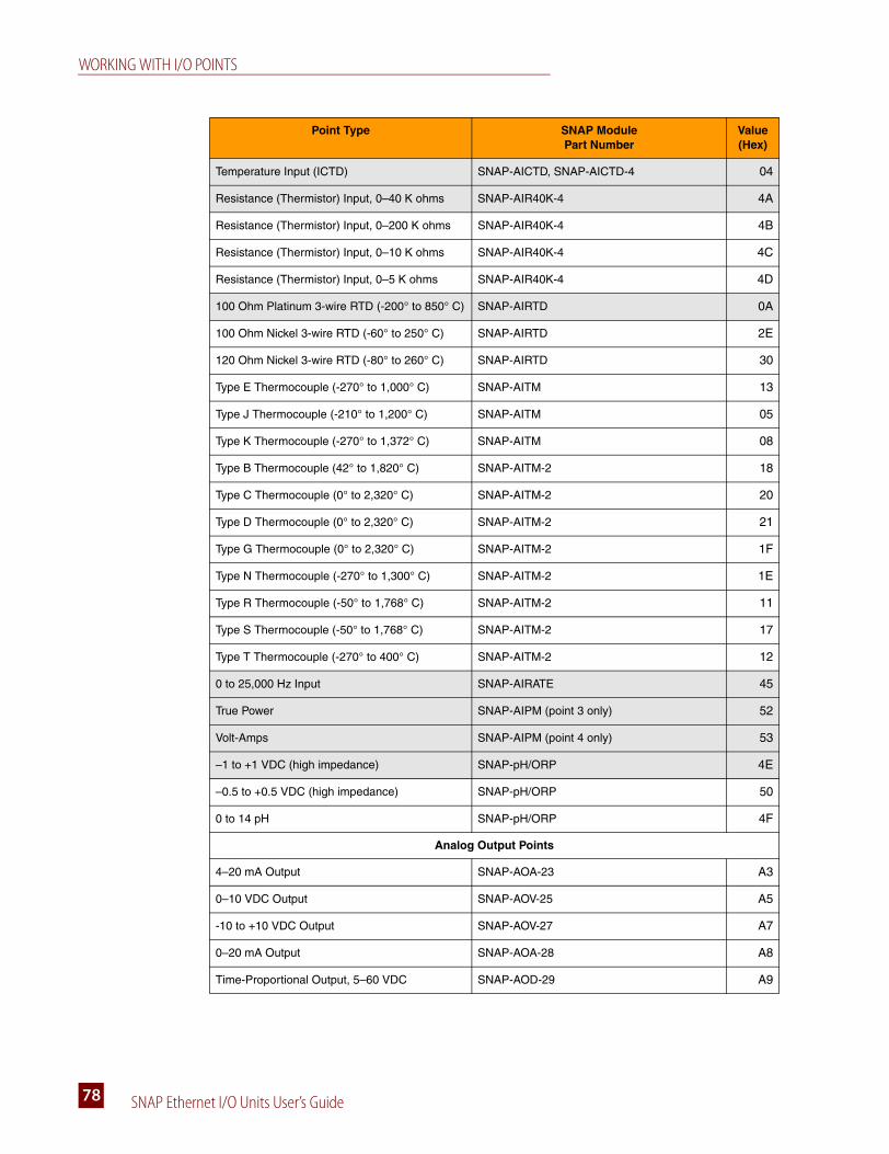
WORKING WITH I/O POINTS
SNAP Ethernet I/O Units User’s Guide78
Temperature Input (ICTD) SNAP-AICTD, SNAP-AICTD-4 04
Resistance (Thermistor) Input, 0–40 K ohms SNAP-AIR40K-4 4A
Resistance (Thermistor) Input, 0–200 K ohms SNAP-AIR40K-4 4B
Resistance (Thermistor) Input, 0–10 K ohms SNAP-AIR40K-4 4C
Resistance (Thermistor) Input, 0–5 K ohms SNAP-AIR40K-4 4D
100 Ohm Platinum 3-wire RTD (-200° to 850° C) SNAP-AIRTD 0A
100 Ohm Nickel 3-wire RTD (-60° to 250° C) SNAP-AIRTD 2E
120 Ohm Nickel 3-wire RTD (-80° to 260° C) SNAP-AIRTD 30
Type E Thermocouple (-270° to 1,000° C) SNAP-AITM 13
Type J Thermocouple (-210° to 1,200° C) SNAP-AITM 05
Type K Thermocouple (-270° to 1,372° C) SNAP-AITM 08
Type B Thermocouple (42° to 1,820° C) SNAP-AITM-2 18
Type C Thermocouple (0° to 2,320° C) SNAP-AITM-2 20
Type D Thermocouple (0° to 2,320° C) SNAP-AITM-2 21
Type G Thermocouple (0° to 2,320° C) SNAP-AITM-2 1F
Type N Thermocouple (-270° to 1,300° C) SNAP-AITM-2 1E
Type R Thermocouple (-50° to 1,768° C) SNAP-AITM-2 11
Type S Thermocouple (-50° to 1,768° C) SNAP-AITM-2 17
Type T Thermocouple (-270° to 400° C) SNAP-AITM-2 12
0 to 25,000 Hz Input SNAP-AIRATE 45
True Power SNAP-AIPM (point 3 only) 52
Volt-Amps SNAP-AIPM (point 4 only) 53
–1 to +1 VDC (high impedance) SNAP-pH/ORP 4E
–0.5 to +0.5 VDC (high impedance) SNAP-pH/ORP 50
0 to 14 pH SNAP-pH/ORP 4F
Analog Output Points
4–20 mA Output SNAP-AOA-23 A3
0–10 VDC Output SNAP-AOV-25 A5
-10 to +10 VDC Output SNAP-AOV-27 A7
0–20 mA Output SNAP-AOA-28 A8
Time-Proportional Output, 5–60 VDC SNAP-AOD-29 A9
Point Type SNAP Module Part Number
Value(Hex)

APPENDIX A: USING MODBUS/TCP
SNAP Ethernet I/O Units User’s Guide 7979
Examples of Configured I/O Points for Modbus
To configure I/O points for Modbus/TCP, write the point configuration data from the previous table to holding registers 641–768. Since the data for this area of the Modbus map is in the form of 32-bit integers, use two consecutive registers to write the data to one point.
For example, look at the table on page 77. If the module in position 0 on the rack is a -5 to +5 V analog input, it is not the default module of that type. Therefore you must configure its points. Now take a look at the Holding Registers section of the Modbus map on page 84. You will write to the Configure Points area, registers 641–768. In this example, let’s assume the analog module has two points. Since it takes two registers per point and the analog module has two points, you write the hex value 0B (for a -5 to +5 V analog input) to the first four registers, 641–644.
As another example, suppose the module in position 1 on the rack is a standard digital output module. Since the default is a standard digital input module, you must configure its points. You write the hex value 180 (for a standard digital output module) to registers 649–656.
The pattern for these two examples looks like this:
Configuring I/O Points for Digital-only Brains
The digital-only SNAP-UP1-D64 and SNAP-ENET-D64 brains assume that all positions on the rack contain standard digital input modules. If a position contains an output module, you must configure its points as outputs.
For example, suppose the module in position 0 on the rack is a standard digital output module. To configure its four points, write a 1 to coils 193–196. See the Memory Map for the digital brain on page 90.
NOTE: Digital-only brains do not support high-density digital modules.
Using I/O Point FeaturesRefer to the “Modbus Memory Map for Most Analog/Digital Brains” on page 82 to find the addresses mentioned in this section. See the “Modbus Memory Map for Digital-Only Brains” on page 90 to find addresses mentioned for the digital-only brain.
Digital Point Features
For explanations of digital point features, see “Additional Information on Features” on page 39.
To these registers: 641642
643644
645646
647648
649650
651652
653654
655656
Write data for these points: 1 2 * * 5 6 7 8
In this position on the rack: 0 1
*Since this analog module has only two points, these registers contain no data.
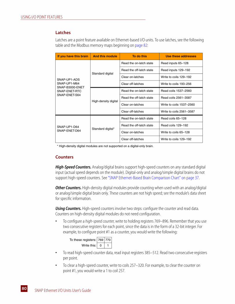
USING I/O POINT FEATURES
SNAP Ethernet I/O Units User’s Guide80
Latches
Latches are a point feature available on Ethernet-based I/O units. To use latches, see the following table and the Modbus memory maps beginning on page 82:
Counters
High-Speed Counters. Analog/digital brains support high-speed counters on any standard digital input (actual speed depends on the module). Digital-only and analog/simple digital brains do not support high-speed counters. See “SNAP Ethernet-Based Brain Comparison Chart” on page 37.
Other Counters. High-density digital modules provide counting when used with an analog/digital or analog/simple digital brain only. These counters are not high speed; see the module’s data sheet for specific information.
Using Counters. High-speed counters involve two steps: configure the counter and read data. Counters on high-density digital modules do not need configuration.
• To configure a high-speed counter, write to holding registers 769–896. Remember that you use two consecutive registers for each point, since the data is in the form of a 32-bit integer. For example, to configure point #1 as a counter, you would write the following:
• To read high-speed counter data, read input registers 385–512. Read two consecutive registers per point.
• To clear a high-speed counter, write to coils 257–320. For example, to clear the counter on point #1, you would write a 1 to coil 257.
If you have this brain And this module To do this Use these addresses
SNAP-UP1-ADSSNAP-UP1-M64 SNAP-B3000-ENETSNAP-ENET-RTCSNAP-ENET-S64
Standard digital
Read the on-latch state Read inputs 65–128
Read the off-latch state Read inputs 129–192
Clear on-latches Write to coils 129–192
Clear off-latches Write to coils 193–256
High-density digital
Read the on-latch state Read coils 1537–2560
Read the off-latch state Read coils 2561–3587
Clear on-latches Write to coils 1537–2560
Clear off-latches Write to coils 2561–3587
SNAP-UP1-D64 SNAP-ENET-D64
Standard digital*
Read the on-latch state Read coils 65–128
Read the off-latch state Read coils 129–192
Clear on-latches Write to coils 65–128
Clear off-latches Write to coils 129–192
* High-density digital modules are not supported on a digital-only brain.
To these registers: 769 770
Write this: 0 1
APPENDIX A: USING MODBUS/TCP
SNAP Ethernet I/O Units User’s Guide 8181
• To read counters on high-density digital modules, read input registers 513–2560 (or read and clear counters using input registers 2561–4608). Read two consecutive registers per point.
Analog Point Features
Analog point features apply to all analog/digital brains. For explanations of analog point features, see “Additional Information on Features” on page 39. To determine whether a brain handles analog modules, see “SNAP Ethernet-Based Brain Comparison Chart” on page 37.
Analog point features generally require that you read or write to two consecutive registers for each point, since the data is in the form of a 32-bit IEEE float. Data is in Big Endian format. You can change the word order if you wish, using the Modbus memory map. See Holding Register 1029 on page 84. If you change word order, be sure to store configuration information to flash (Holding Register 1026) so it will be saved when the brain is turned off.
Scaling
To scale an analog point, write the low-scale value to holding registers 385–512 and the high-scale value to holding registers 513–640. Write to two consecutive registers for each point you are scaling.
Minimum and Maximum Values
Minimum and maximum values are analog point features. The brain automatically keeps track of minimum and maximum values. You can read the values at any time, for example to record minimum and maximum temperatures. You can also clear them.
• To read min/max values, read input registers 129–384. Read two consecutive addresses per point.
• To clear min/max values, write 1 bits to coils 321–448. Exception: SNAP-UP1-M64 and SNAP-ENET-S64 brains use these coils for other purposes. To clear minimum and maximum values on these brains, use the memory map. For instructions, see the Modbus chapter in Opto 22 form #1465, the OptoMMP Protocol Guide.
Offset and Gain
Offset and gain are also analog point features. Setting offset and gain for analog input points is important to make sure that values appear accurately when read. If a -50 mV to +50 mV input receives signals that are slightly off (not exactly -50 mV at the lowest point, for example), you can set offset and gain to adjust them.
Calculate offset first, and then calculate gain. The offset must be calculated at the point’s low scale, and the gain must be calculated at the point’s high scale.
Once you have calculated offset and gain values, write them to the brain. To set offset, write to holding registers 129–256, using two consecutive addresses per point. To set gain, write to holding registers 257–384.

MODBUS MEMORY MAP FOR MOST ANALOG/DIGITAL BRAINS
SNAP Ethernet I/O Units User’s Guide82
Modbus Memory Map for Most Analog/Digital BrainsThe following tables show the Modbus map for the following analog/digital brains:
For digital-only brains, see page 90. For analog/simple digital brains, see page 87.
If you need to take other actions besides those shown in these tables, see the Modbus chapter in form #1465, the OptoMMP Protocol Guide.
NOTE: Because digital counters and module configuration require more than one bit, they are handled in input and holding registers.
Coils
For standard digital I/O and analog minimum/maximum values: Since up to 64 points are available on the largest SNAP I/O rack, digital coils contain 64 addresses. Each address contains the data for one point. Data is either 0 or 1.
For high-density digital I/O: Coils contain 512 addresses, with an extra 512 addresses reserved. See “Notes for High-Density Digital Modules” on page 85.
SNAP-UP1-ADS SNAP-B3000-ENET SNAP-ENET-RTC
Coil Numbers Action Notes
1–64 Read or Write Standard Digital Outputs 1 = On, 0 = Off
65–128 Activate Counters (Standard digital modules)1 = On, 0 = Off. Configure as a point fea-ture first. See “Counters” on page 80.
129–192 Clear On-latch (Standard digital modules) 1 = clear latches; 0 = do nothing
193–256 Clear Off-latch (Standard digital modules) 1 = clear latches; 0 = do nothing
257–320 Clear Counters (Standard digital modules) 1 = clear counters; 0 = do nothing
321–384 Clear Analog Minimum Values 1 = clear minimum values; 0 = do nothing
385–448 Clear Analog Maximum Values 1 = clear maximum values; 0 = do nothing
513–1536 Read or Write High-Density Digital Modules 1 = On, 0 = Off
1537–2560 Clear On-latch (High-density digital modules) 1 = clear latches; 0 = do nothing
2561–3584 Clear Off-latch (High-density digital modules) 1 = clear latches; 0 = do nothing

APPENDIX A: USING MODBUS/TCP
SNAP Ethernet I/O Units User’s Guide 8383
Inputs
Standard digital inputs also contain 64 addresses, each with the data for one point. Data is either 0 or 1.
High-density digital inputs contain 512 addresses, with an extra 512 addresses reserved. See “Notes for High-Density Digital Modules” on page 85.
Input Registers
Input register data is in the form of 32-bit floats or 32-bit integers. Because Modbus registers contain only 16 bits, you must use two consecutive registers to read the data for one point, starting with an odd-numbered register. See the example on page 85.
For high-density digital modules, see “Notes for High-Density Digital Modules” on page 85.
You can read a maximum of 127 registers in one command.
Input Numbers Action Notes
1–64 Read Standard Digital Inputs 1 = On, 0 = Off
65–128 Read State of On-latches (Standard digital modules) 1 = On, 0 = Off
129–192 Read State of Off-latches (Standard digital modules) 1 = On, 0 = Off
193–256 Read Counter Active State (Standard digital modules) 1 = Active, 0 = Inactive
513–1536 Read High-Density Digital Modules 1 = On, 0 = Off
1537–2560 Read On-Latches (High-density digital modules) 1 = On, 0 = Off
2561–3584 Read Off-Latches (High-density digital modules) 1 = On, 0 = Off
Register Numbers Action Notes
1–128 Read Analog Values IEEE 32-bit float
129–256 Read Analog Minimum Values (Inputs only) IEEE 32-bit float
257–384 Read Analog Maximum Values (Inputs only) IEEE 32-bit float
385–512 Read Digital Counter Data (Standard digital modules) 32-bit integer
513–2560 Read Digital Counter Data (High-density digital modules) 32-bit integer
2561–4608 Read and Clear Digital Counter Data (High-density modules) 32-bit integer
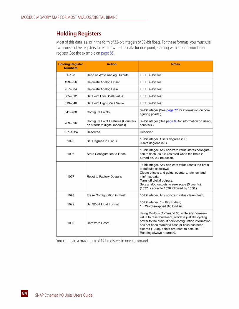
MODBUS MEMORY MAP FOR MOST ANALOG/DIGITAL BRAINS
SNAP Ethernet I/O Units User’s Guide84
Holding Registers
Most of this data is also in the form of 32-bit integers or 32-bit floats. For these formats, you must use two consecutive registers to read or write the data for one point, starting with an odd-numbered register. See the example on page 85.
You can read a maximum of 127 registers in one command.
Holding Register Numbers
Action Notes
1–128 Read or Write Analog Outputs IEEE 32-bit float
129–256 Calculate Analog Offset IEEE 32-bit float
257–384 Calculate Analog Gain IEEE 32-bit float
385–512 Set Point Low Scale Value IEEE 32-bit float
513–640 Set Point High Scale Value IEEE 32-bit float
641–768 Configure Points32-bit integer (See page 77 for information on con-figuring points.)
769–896Configure Point Features (Counters on standard digital modules)
32-bit integer (See page 80 for information on using counters.)
897–1024 Reserved Reserved
1025 Set Degrees in F or C16-bit integer. 1 sets degrees in F; 0 sets degrees in C.
1026 Store Configuration to Flash16-bit integer. Any non-zero value stores configura-tion to flash, so it is restored when the brain is turned on. 0 = no action.
1027 Reset to Factory Defaults
16-bit integer. Any non-zero value resets the brain to defaults as follows:Clears offsets and gains, counters, latches, and min/max data.Turns off digital outputs.Sets analog outputs to zero scale (0 counts).(1027 is equal to 1028 followed by 1030.)
1028 Erase Configuration in Flash 16-bit integer. Any non-zero value clears flash.
1029 Set 32-bit Float Format16-bit integer. 0 = Big Endian; 1 = Word-swapped Big Endian.
1030 Hardware Reset
Using Modbus Command 06, write any non-zero value to reset hardware, which is just like cycling power to the brain. If point configuration information has not been stored to flash or flash has been cleared (1028), points are reset to defaults.Reading always returns 0.
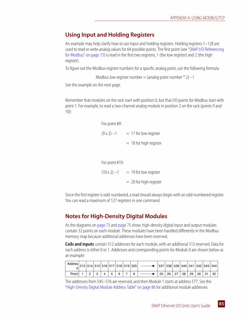
APPENDIX A: USING MODBUS/TCP
SNAP Ethernet I/O Units User’s Guide 8585
Using Input and Holding Registers
An example may help clarify how to use input and holding registers. Holding registers 1–128 are used to read or write analog values for 64 possible points. The first point (see “SNAP I/O Referencing for Modbus” on page 73) is read in the first two registers, 1 (the low register) and 2 (the high register).
To figure out the Modbus register numbers for a specific analog point, use the following formula:
Modbus low register number = (analog point number * 2) –1
See the example on the next page.
Remember that modules on the rack start with position 0, but that I/O points for Modbus start with point 1. For example, to read a two-channel analog module in position 2 on the rack (points 9 and 10):
Since the first register is odd-numbered, a read should always begin with an odd-numbered register. You can read a maximum of 127 registers in one command.
Notes for High-Density Digital Modules
As the diagrams on page 73 and page 75 show, high-density digital input and output modules contain 32 points on each module. These modules have been handled differently in the Modbus memory map because additional addresses have been reserved.
Coils and inputs contain 512 addresses for each module, with an additional 512 reserved. Data for each address is either 0 or 1. Addresses and corresponding points for Module 0 are shown below as an example:
The addresses from 545–576 are reserved, and then Module 1 starts at address 577. See the “High-Density Digital Module Address Table” on page 86 for additional module addresses.
For point #9:
(9 x 2) –1 = 17 for low register
= 18 for high register
For point #10:
(10 x 2) –1 = 19 for low register
= 20 for high register
Address
513 514 515 516 517 518 519 520 537 538 539 540 541 542 543 544
Point 1 2 3 4 5 6 7 8 25 26 27 28 29 30 31 32

MODBUS MEMORY MAP FOR MOST ANALOG/DIGITAL BRAINS
SNAP Ethernet I/O Units User’s Guide86
Registers contain 1024 addresses for each module (since the data for each point requires two registers), and an additional 1024 addresses are reserved. For example:
Addresses 577–640 are reserved, and then Module 1 starts at 641. See the “High-Density Digital Module Address Table” on page 86 for additional module addresses.
High-Density Digital Module Address Table
Starting addresses for each module are shown.
Address
513514
515516
517518
519520
521522
523524
525526
527528
561562
563564
565566
567568
569570
571572
573574
575576
Point 1 2 3 4 5 6 7 8 25 26 27 28 29 30 31 32
Module Position
Coils/Inputs Input Registers
State On-Latch State Off-Latch State Counter Data Read & Clear Counter
0 513 1537 2561 513 2561
1 577 1601 2625 641 2689
2 641 1665 2689 769 2817
3 705 1729 2753 897 2945
4 769 1793 2817 1025 3073
5 833 1857 2881 1153 3201
6 897 1921 2945 1281 3329
7 961 1985 3009 1409 3457
8 1025 2049 3073 1537 3585
9 1089 2113 3137 1665 3713
10 1153 2177 3201 1793 3841
11 1217 2241 3265 1921 3969
12 1281 2305 3329 2049 4097
13 1345 2369 3393 2177 4225
14 1409 2433 3457 2305 4353
15 1473 2497 3521 2433 4481
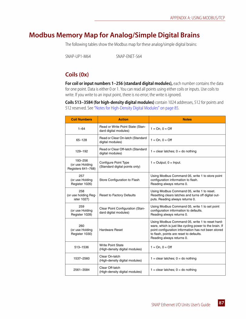
APPENDIX A: USING MODBUS/TCP
SNAP Ethernet I/O Units User’s Guide 8787
Modbus Memory Map for Analog/Simple Digital BrainsThe following tables show the Modbus map for these analog/simple digital brains:
Coils (0x)
For coil or input numbers 1–256 (standard digital modules), each number contains the data for one point. Data is either 0 or 1. You can read all points using either coils or inputs. Use coils to write. If you write to an input point, there is no error; the write is ignored.
Coils 513–3584 (for high-density digital modules) contain 1024 addresses, 512 for points and 512 reserved. See “Notes for High-Density Digital Modules” on page 85.
SNAP-UP1-M64 SNAP-ENET-S64
Coil Numbers Action Notes
1–64Read or Write Point State (Stan-dard digital modules)
1 = On, 0 = Off
65–128Read or Clear On-latch (Standard digital modules)
1 = On, 0 = Off
129–192Read or Clear Off-latch (Standard digital modules)
1 = clear latches; 0 = do nothing
193–256(or use Holding
Registers 641–768)
Configure Point Type(Standard digital points only)
1 = Output; 0 = Input.
257(or use Holding Register 1026)
Store Configuration to FlashUsing Modbus Command 05, write 1 to store point configuration information to flash. Reading always returns 0.
258(or use holding Reg-
ister 1027)Reset to Factory Defaults
Using Modbus Command 05, write 1 to reset. Resetting clears latches and turns off digital out-puts. Reading always returns 0.
259(or use Holding Register 1028)
Clear Point Configuration (Stan-dard digital modules)
Using Modbus Command 05, write 1 to set point configuration information to defaults.Reading always returns 0.
260(or use Holding Register 1030)
Hardware Reset
Using Modbus Command 05, write 1 to reset hard-ware, which is just like cycling power to the brain. If point configuration information has not been stored to flash, points are reset to defaults.Reading always returns 0.
513–1536Write Point State (High-density digital modules)
1 = On, 0 = Off
1537–2560Clear On-latch (High-density digital modules)
1 = clear latches; 0 = do nothing
2561–3584Clear Off-latch (High-density digital modules)
1 = clear latches; 0 = do nothing
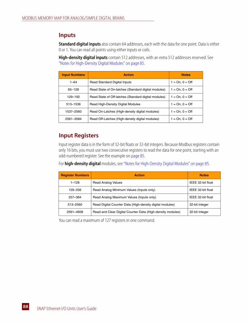
MODBUS MEMORY MAP FOR ANALOG/SIMPLE DIGITAL BRAINS
SNAP Ethernet I/O Units User’s Guide88
Inputs
Standard digital inputs also contain 64 addresses, each with the data for one point. Data is either 0 or 1. You can read all points using either inputs or coils.
High-density digital inputs contain 512 addresses, with an extra 512 addresses reserved. See “Notes for High-Density Digital Modules” on page 85.
Input Registers
Input register data is in the form of 32-bit floats or 32-bit integers. Because Modbus registers contain only 16 bits, you must use two consecutive registers to read the data for one point, starting with an odd-numbered register. See the example on page 85.
For high-density digital modules, see “Notes for High-Density Digital Modules” on page 85.
You can read a maximum of 127 registers in one command.
Input Numbers Action Notes
1–64 Read Standard Digital Inputs 1 = On, 0 = Off
65–128 Read State of On-latches (Standard digital modules) 1 = On, 0 = Off
129–192 Read State of Off-latches (Standard digital modules) 1 = On, 0 = Off
513–1536 Read High-Density Digital Modules 1 = On, 0 = Off
1537–2560 Read On-Latches (High-density digital modules) 1 = On, 0 = Off
2561–3584 Read Off-Latches (High-density digital modules) 1 = On, 0 = Off
Register Numbers Action Notes
1–128 Read Analog Values IEEE 32-bit float
129–256 Read Analog Minimum Values (Inputs only) IEEE 32-bit float
257–384 Read Analog Maximum Values (Inputs only) IEEE 32-bit float
513–2560 Read Digital Counter Data (High-density digital modules) 32-bit integer
2561–4608 Read and Clear Digital Counter Data (High-density modules) 32-bit integer
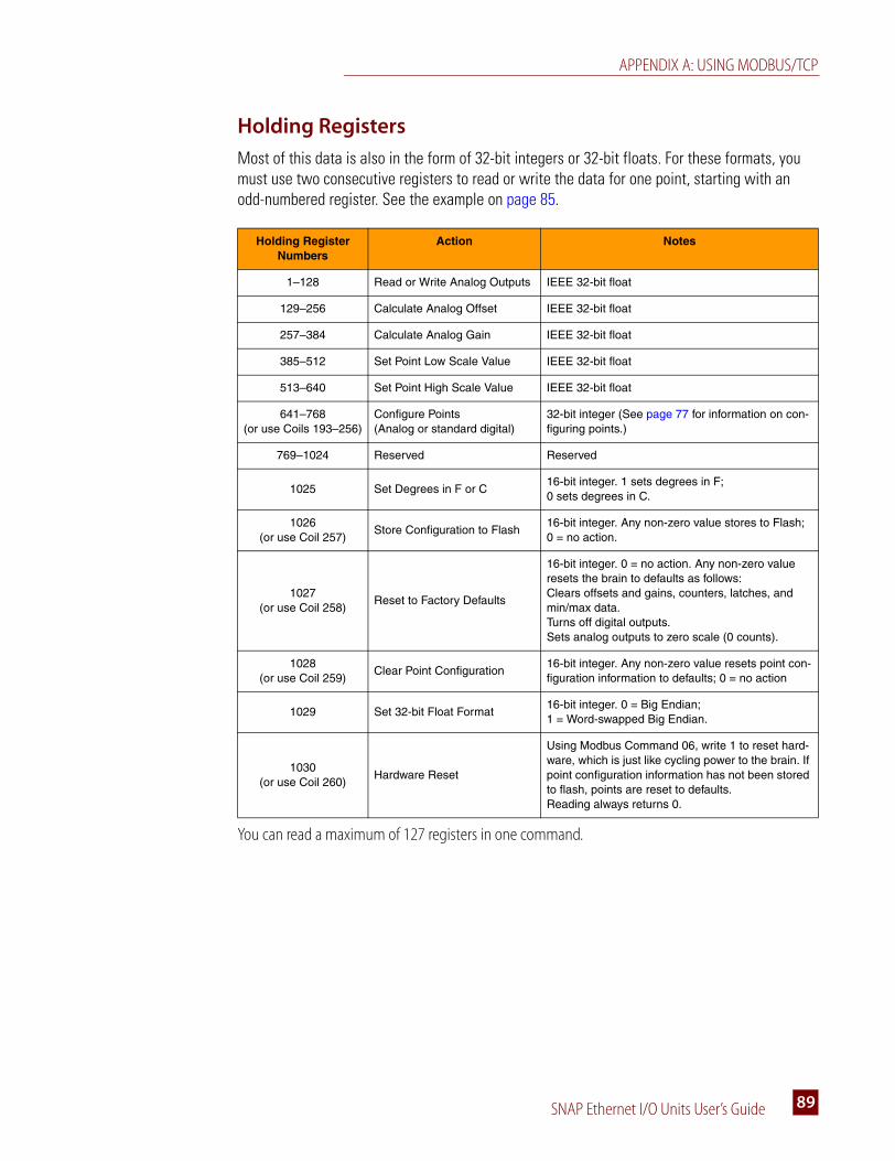
APPENDIX A: USING MODBUS/TCP
SNAP Ethernet I/O Units User’s Guide 8989
Holding Registers
Most of this data is also in the form of 32-bit integers or 32-bit floats. For these formats, you must use two consecutive registers to read or write the data for one point, starting with an odd-numbered register. See the example on page 85.
You can read a maximum of 127 registers in one command.
Holding Register Numbers
Action Notes
1–128 Read or Write Analog Outputs IEEE 32-bit float
129–256 Calculate Analog Offset IEEE 32-bit float
257–384 Calculate Analog Gain IEEE 32-bit float
385–512 Set Point Low Scale Value IEEE 32-bit float
513–640 Set Point High Scale Value IEEE 32-bit float
641–768(or use Coils 193–256)
Configure Points(Analog or standard digital)
32-bit integer (See page 77 for information on con-figuring points.)
769–1024 Reserved Reserved
1025 Set Degrees in F or C16-bit integer. 1 sets degrees in F; 0 sets degrees in C.
1026(or use Coil 257)
Store Configuration to Flash16-bit integer. Any non-zero value stores to Flash; 0 = no action.
1027(or use Coil 258)
Reset to Factory Defaults
16-bit integer. 0 = no action. Any non-zero value resets the brain to defaults as follows:Clears offsets and gains, counters, latches, and min/max data.Turns off digital outputs.Sets analog outputs to zero scale (0 counts).
1028(or use Coil 259)
Clear Point Configuration16-bit integer. Any non-zero value resets point con-figuration information to defaults; 0 = no action
1029 Set 32-bit Float Format16-bit integer. 0 = Big Endian; 1 = Word-swapped Big Endian.
1030(or use Coil 260)
Hardware Reset
Using Modbus Command 06, write 1 to reset hard-ware, which is just like cycling power to the brain. If point configuration information has not been stored to flash, points are reset to defaults.Reading always returns 0.
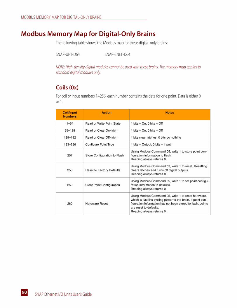
MODBUS MEMORY MAP FOR DIGITAL-ONLY BRAINS
SNAP Ethernet I/O Units User’s Guide90
Modbus Memory Map for Digital-Only BrainsThe following table shows the Modbus map for these digital-only brains:
NOTE: High-density digital modules cannot be used with these brains. The memory map applies to standard digital modules only.
Coils (0x)
For coil or input numbers 1–256, each number contains the data for one point. Data is either 0 or 1.
SNAP-UP1-D64 SNAP-ENET-D64
Coil/Input Numbers
Action Notes
1–64 Read or Write Point State 1 bits = On, 0 bits = Off
65–128 Read or Clear On-latch 1 bits = On, 0 bits = Off
129–192 Read or Clear Off-latch 1 bits clear latches; 0 bits do nothing
193–256 Configure Point Type 1 bits = Output; 0 bits = Input
257 Store Configuration to FlashUsing Modbus Command 05, write 1 to store point con-figuration information to flash. Reading always returns 0.
258 Reset to Factory DefaultsUsing Modbus Command 05, write 1 to reset. Resetting clears latches and turns off digital outputs. Reading always returns 0.
259 Clear Point ConfigurationUsing Modbus Command 05, write 1 to set point configu-ration information to defaults.Reading always returns 0.
260 Hardware Reset
Using Modbus Command 05, write 1 to reset hardware, which is just like cycling power to the brain. If point con-figuration information has not been stored to flash, points are reset to defaults.Reading always returns 0.

SNAP Ethernet I/O Units User’s Guide 9191
Appendix BS
SNAP I/O Wiring Diagrams
IntroductionThis appendix includes wiring diagram examples for assembling your Ethernet-based I/O system and attaching it to the devices it will monitor and control. The system includes the Ethernet-based processor (brain or rack-mounted controller) and SNAP I/O modules mounted on a SNAP rack, powered by a SNAP power supply.
Example: SNAP Ethernet I/O system, partly assembled
This document includes basic wiring information for SNAP racks, power supplies, processors (brains or rack-mounted controllers), and I/O modules. For more information, see the data sheet and the installation or user’s guide for your specific products.
Processor (rack-mounted controller or brain)
Power supply
Rack
Modules

SNAP MOUNTING RACKS
SNAP Ethernet I/O Units User’s Guide92
SNAP Mounting RacksSNAP mounting racks can hold a SNAP processor (brain or rack-mounted controller) and up to 4, 8, 12, or 16 SNAP modules.
The following table shows SNAP rack and processor compatibility. “Processor” refers to a brain or a rack-mounted controller. “Mixed” means that a rack can hold both analog and digital modules, plus serial and high-density digital modules if the processor supports them.
Racks Without Terminal Strips
SNAP racks come either with or without a common terminal strip. The following diagram shows a rack without a terminal strip. For this type of rack, all wiring connections are made to the field
Processor Part Number
Compatible Racks
Rack Description
SNAP-UP1-M64SNAP-ENET-S64
SNAP-M164-module mixed (digital functions depend on processor;standard and high-density digital modules OK)
SNAP-M328-module mixed (digital functions depend on processor; standard and high-density digital modules OK)
SNAP-M4812-module mixed (digital functions depend on processor; stan-dard and high-density digital modules OK)
SNAP-M6416-module mixed (digital functions depend on processor; stan-dard and high-density digital modules OK)
SNAP-UP1-ADSSNAP-B3000-ENETSNAP-ENET-RTC
SNAP-B4M 4-module mixed
SNAP-B8M 8-module mixed
SNAP-B8MC 8-module mixed, terminal block
SNAP-B8MC-P 8-module mixed, pluggable terminal block
SNAP-B12M 12-module mixed (standard digital in positions 0–7 only)
SNAP-B12MC12-module mixed (standard digital in positions 0–7 only), terminal block
SNAP-B12MC-P12-module mixed (standard digital in positions 0–7 only), pluggable terminal block
SNAP-B16M 16-module mixed (standard digital in positions 0–7 only)
SNAP-B16MC16-module mixed (standard digital in positions 0–7 only), terminal block
SNAP-B16MC-P16-module mixed (standard digital in positions 0–7 only), pluggable terminal block
SNAP-UP1-D64SNAP-ENET-D64
SNAP-D64RS16-module digital only (limited digital functions; standard digital modules only)

APPENDIX B: SNAP I/O WIRING DIAGRAMS
SNAP Ethernet I/O Units User’s Guide 9393
connectors on the top of each module. A processor is shown on this rack, but the modules have not been inserted yet.
Racks with Terminal Strips
If your rack has a terminal strip, you can use it for field wiring common connections, such as loop power distribution, or low-current applications. The following diagram shows a rack with a terminal strip (MC rack models); the smaller diagram shows the optional terminal strip with pluggable connectors (MC-P rack models). Terminal strips do not connect to SNAP modules; depending on

SNAP POWER SUPPLIES
SNAP Ethernet I/O Units User’s Guide94
your application, you may need to install wiring from the terminal strip to the module. (Again, the rack is shown with a processor but with no modules.)
SNAP Power Supplies
Primary Power Supply
NOTE: For a more general discussion of using power supplies with Opto 22 systems, see Opto 22 form #1271, a technical note available on our website at www.opto22.com.
SNAP racks use a 5 VDC power source (5 VDC [-0.0, +0.1] at minimum 4.0 Amps recommended). For systems using AC source voltage, the SNAP-PS5 or SNAP-PS5U power supply is recommended. For DC systems, such as those using DC backup power, the SNAP-PS5-24DC offers DC-to-DC power.
In general, we recommend you use an independent, isolated, regulated power supply locally with each rack. Local isolated supplies offer these advantages:
• Short supply conductors, which minimize losses
• Power redundancy, so the failure of a single supply causes only a single rack failure, not a total system failure
• Fewer voltage drops and ground loops. (Voltage drops and subsequent ground loops may occur when power is distributed over a large system.)
Always use a separate power supply for the field side of the I/O. Using the rack supply for field actuation and monitoring defeats the isolation the I/O module offers and therefore increases the chance of a ground loop within the control system. Additionally, a sudden change of current on the
Terminal strip (MC models)
Terminal strip with pluggable connectors (MC-P models)
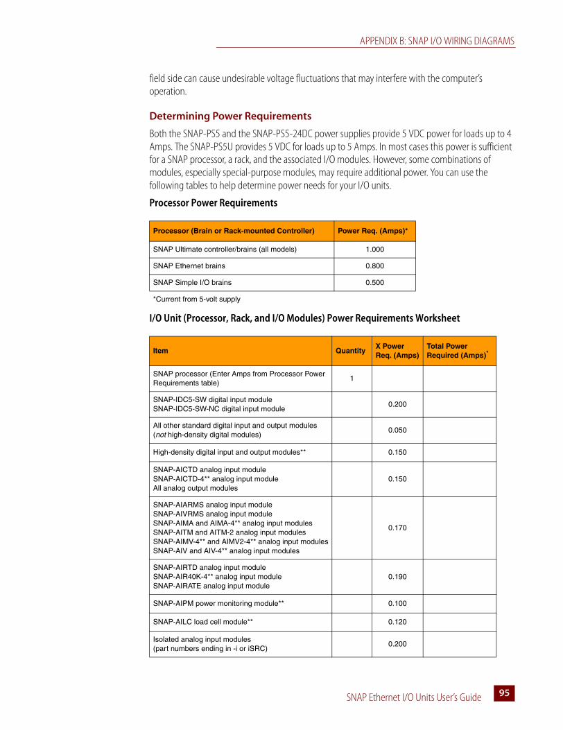
APPENDIX B: SNAP I/O WIRING DIAGRAMS
SNAP Ethernet I/O Units User’s Guide 9595
field side can cause undesirable voltage fluctuations that may interfere with the computer’s operation.
Determining Power Requirements
Both the SNAP-PS5 and the SNAP-PS5-24DC power supplies provide 5 VDC power for loads up to 4 Amps. The SNAP-PS5U provides 5 VDC for loads up to 5 Amps. In most cases this power is sufficient for a SNAP processor, a rack, and the associated I/O modules. However, some combinations of modules, especially special-purpose modules, may require additional power. You can use the following tables to help determine power needs for your I/O units.
Processor Power Requirements
I/O Unit (Processor, Rack, and I/O Modules) Power Requirements Worksheet
Processor (Brain or Rack-mounted Controller) Power Req. (Amps)*
SNAP Ultimate controller/brains (all models) 1.000
SNAP Ethernet brains 0.800
SNAP Simple I/O brains 0.500
*Current from 5-volt supply
Item QuantityX Power Req. (Amps)
Total Power Required (Amps)*
SNAP processor (Enter Amps from Processor Power Requirements table)
1
SNAP-IDC5-SW digital input moduleSNAP-IDC5-SW-NC digital input module
0.200
All other standard digital input and output modules (not high-density digital modules)
0.050
High-density digital input and output modules** 0.150
SNAP-AICTD analog input moduleSNAP-AICTD-4** analog input moduleAll analog output modules
0.150
SNAP-AIARMS analog input moduleSNAP-AIVRMS analog input moduleSNAP-AIMA and AIMA-4** analog input modulesSNAP-AITM and AITM-2 analog input modulesSNAP-AIMV-4** and AIMV2-4** analog input modulesSNAP-AIV and AIV-4** analog input modules
0.170
SNAP-AIRTD analog input moduleSNAP-AIR40K-4** analog input moduleSNAP-AIRATE analog input module
0.190
SNAP-AIPM power monitoring module** 0.100
SNAP-AILC load cell module** 0.120
Isolated analog input modules(part numbers ending in -i or iSRC)
0.200

SNAP POWER SUPPLIES
SNAP Ethernet I/O Units User’s Guide96
IMPORTANT: For a SNAP-PS5 or a SNAP-PS5-24DC power supply, the total power required must not exceed 4 Amps. For a SNAP-PS5U, the total power required must not exceed 5 Amps.
Wiring the Primary Power Supply
Use one power supply per I/O unit. Use 14 AWG wire.
1. Mount the SNAP-PS5 or SNAP-PS5-24DC power supply so that the attached red and black power wires will reach the + and – power terminals on the SNAP mounting rack.
2. Using the power terminals on the SNAP mounting rack, attach the red wire to the + terminal and the black wire to the – terminal. Connect the ground terminal on the SNAP rack to ground.
3. For the SNAP-PS5 (not illustrated): Using the removable input power connector on top of the power supply, apply 120 volts AC power between the two terminals marked “AC.” Connect the ground terminal to ground.
4. For the SNAP-PS5U (not illustrated): Using the removable input power connector on top of the power supply, apply 240 or 120 volts AC power between the two terminals marked “AC.” Connect the ground terminal to ground.
Serial or Profibus modules** 0.250
Total* Current from 5-volt supply** Can be used with SNAP Simple, SNAP Ethernet, and SNAP Ultimate
Item QuantityX Power Req. (Amps)
Total Power Required (Amps)*

APPENDIX B: SNAP I/O WIRING DIAGRAMS
SNAP Ethernet I/O Units User’s Guide 9797
5. For the SNAP-PS5-24DC (illustrated below): Using the removable input power connector on top of the power supply, apply 24 volts DC power between the two terminals marked “±DC.” Connect the ground terminal to ground.
Loop Power Supply
Some analog modules (SNAP-AIMA, SNAP-AIMA-4, SNAP-AIMA-i, SNAP-AIMA2-i) also require a current loop supply, which can be provided by the SNAP-PS24 or the SNAP-PS24U. Both offer 24 volts of DC power, the SNAP-PS24 at .75 A and the SNAP-PS24U at 1.25 A. Follow these steps to wire these power supplies.
1. Mount the SNAP-PS24 or SNAP-PS24U power supply in a location where the attached output power wires will reach the field connector for SNAP analog modules.
The white and red wire is the positive wire (24 VDC). The white and black wire is the negative wire (24 VDC return).
2. If you are wiring directly to the module, see the wiring diagram for the specific module you are using.
Examples for an input module are shown in the following diagrams.
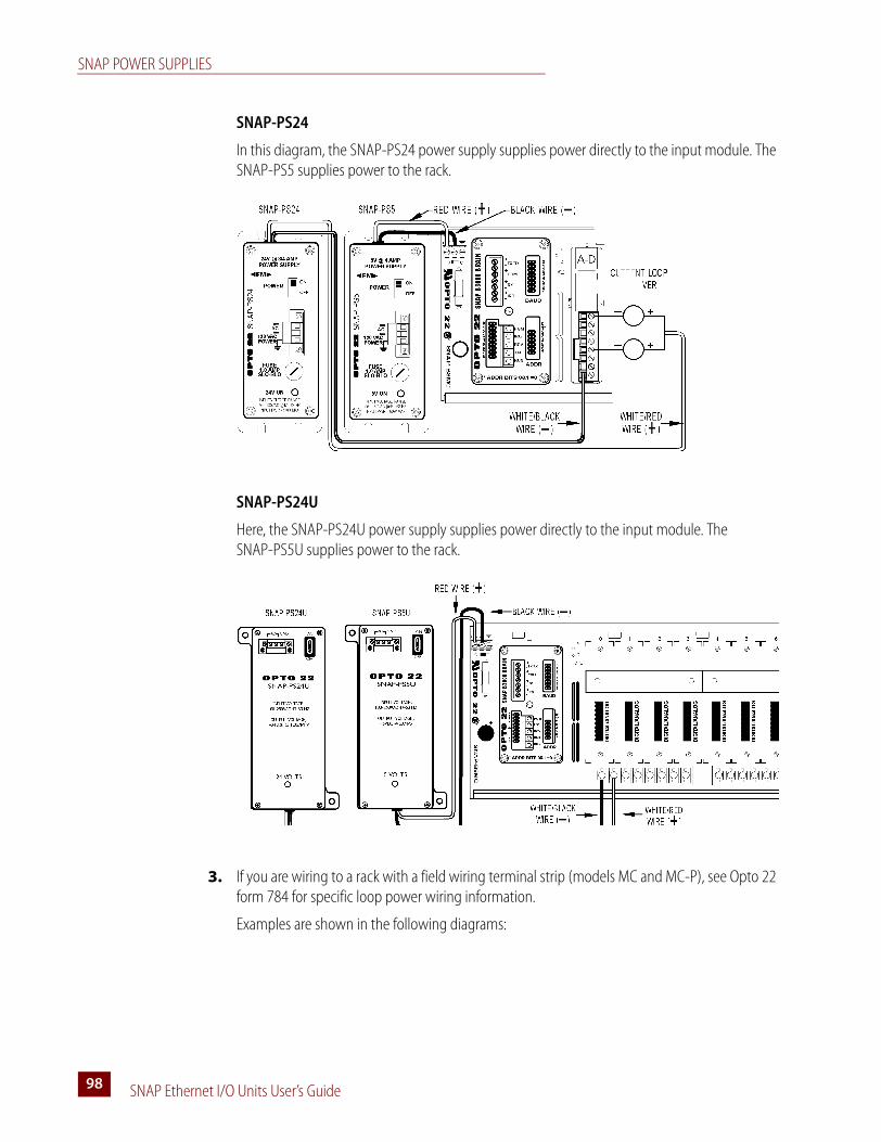
SNAP POWER SUPPLIES
SNAP Ethernet I/O Units User’s Guide98
SNAP-PS24
In this diagram, the SNAP-PS24 power supply supplies power directly to the input module. The SNAP-PS5 supplies power to the rack.
SNAP-PS24U
Here, the SNAP-PS24U power supply supplies power directly to the input module. The SNAP-PS5U supplies power to the rack.
3. If you are wiring to a rack with a field wiring terminal strip (models MC and MC-P), see Opto 22 form 784 for specific loop power wiring information.
Examples are shown in the following diagrams:

APPENDIX B: SNAP I/O WIRING DIAGRAMS
SNAP Ethernet I/O Units User’s Guide 9999
SNAP-PS24
In this diagram, the SNAP-PS24 power supply supplies power directly to the input module. The SNAP-PS5 supplies power to the rack.
SNAP-PS24U
Here, the SNAP-PS24U power supply supplies power directly to the input module. The SNAP-PS5U supplies power to the rack.
4. Connect the ground terminal to ground. Using the removable input power connector on top of the power supply, apply 120 volts of AC power between the two terminals marked AC.

SNAP PROCESSORS
SNAP Ethernet I/O Units User’s Guide100
SNAP ProcessorsRefer to “SNAP Mounting Racks” on page 92. Make certain you have a compatible processor and rack before you begin.
1. Assemble the rack, power supply, and modules according to the directions that came with them.
CAUTION: Make certain that you have the correct SNAP rack for the processor (brain or rack-mounted controller) you are using. Using the wrong rack will severely damage the processor.
2. Remove the processor from its packaging.
3. Turn off power to the rack assembly.
4. Align the processor’s connector with the mating connector on the mounting rack, as shown in the diagram at right.
5. Seat the processor onto the connector and use the hold-down screw to secure it in position. Do not overtighten.
6. Using Category 5 or superior solid unshielded twisted-pair cable, connect the processor in one of the following ways:
– (Recommended for initial configuration) Connect to a PC directly, using an Ethernet crossover cable.
– Connect to a standard 10BASE-T or 100BASE-TX Ethernet network that has a PC on the same subnet as the processor and does NOT have a Dynamic Host Configuration Protocol (DHCP) server.
Maximum cable or segment length is 100 meters; minimum cable length is one meter.
7. Follow instructions in the processor’s data sheet or user’s guide for communications wiring and jumper settings, if applicable.
APPENDIX B: SNAP I/O WIRING DIAGRAMS
SNAP Ethernet I/O Units User’s Guide 101101
SNAP I/O ModulesSNAP digital modules are either 4-channel or 32-channel. SNAP analog modules range from one to eight channels.
SNAP Digital Applications
Q: What is the difference between the SRC and SNK digital DC output modules?
A: SRC and SNK stand for SouRCing and SiNKing, respectively. Because one fuse is used for all four output channels on the module, Opto 22 designed two different varieties. The selection of the module type depends on which side of the load the module is placed on. Typically, a SRC module is used between the + terminal and the load, while a SNK module would be used between the load and the –, ground, or common terminal. Please note that if the wrong module is used in the wrong place, all four channels will effectively become common and all four loads will be activated if any one channel is turned on.
Q: Why is there only one digital AC output module, when there are two DC modules?
A: Only one AC module design is required, because the switching devices used in the AC module are non-polar, unlike the transistors used in the DC modules. So the AC module may be used for sourcing or sinking, as long as all four channels on the module are wired in the same way.
Q: Is there any way to get more than 0.75 A current capacity out of each channel on the digital output module?
A: Yes. SNAP digital output modules are not rated on a channel-to-channel basis; instead, the entire module is rated for a maximum of 3 A. Any one channel on the module can carry up to 3 A, as long as the total current being carried by the module is 3 A or less. Thus, two of four channels can be used to carry 1.5 A each, with two channels unused.
Q: Can I wire the channels on a SNAP digital output module in parallel to obtain a higher current rating?
A: This question is related to the question above. There really isn’t a need to wire channels in parallel, because each channel can carry up to 3 A; just be certain that the total current passing through the module is 3 A or less. Wiring the channels in parallel will not make any difference as far as performance goes; one channel will likely activate before the others and thus take up the entire load itself anyway. Parallel wiring does allow for some automatic fallback redundancy in case one channel fails open, however.
Q: Is there a SNAP digital input module for DC voltages over 32 V?
A: Yes. SNAP AC input modules may be used for DC input up to their voltage rating. For example, a SNAP IAC5 can be used to read 125 VDC input signals. Most SNAP input modules use a full-wave rectifier on the input, allowing the module to be used as an AC or DC input and making it resistant to reversed-polarity installations.
SNAP I/O MODULES
SNAP Ethernet I/O Units User’s Guide102
Q: Is there a way to read low-voltage AC signals with a SNAP input module?
A: Yes. In the same way that SNAP AC modules can be used for DC, some SNAP DC modules can be used to take low-voltage AC signals, such as the 24 VAC commonly used in HVAC systems. This is allowable with all SNAP DC modules containing a full-wave rectifier.
Q: Does Opto 22 make a SNAP digital input module for high-speed signals? Or for quadrature input use?
A: Yes, and we offer many other digital input modules as well. For a complete list, see the Opto 22 website.
Q: What sort of isolation is provided by Opto 22 SNAP digital modules?
A: SNAP digital modules are optically isolated against transient voltages to 4,000 Vrms between the field and logic connections. Input modules are isolated up to 300 VAC between each channel on the module. There is no isolation from channel to channel on most digital output modules, due to the common connection on each module for fusing purposes, but isolated output modules are available.
SNAP Analog Applications
Q: What types of SNAP analog modules are available?
A: The software-configurable SNAP analog modules handle a wide variety of signal types, including voltage, current, rate, temperature, RMS, and more. New modules are added frequently. See the Opto 22 website for models and specifications.
Q: What type of resolution do SNAP analog inputs provide?
A: SNAP analog input modules have a typical resolution of ±25,000 counts. This equates to roughly 14.5-bit resolution plus sign, or 15.5-bit full-scale resolution. These odd resolutions are a result of the inherent accuracy of the input amplifiers used to buffer the analog-to-digital converter from the signal source. While the analog-to-digital converter may be capable of providing higher resolution numbers, they are essentially useless because of the precision level of the signal conditioning circuitry and the amount of noise inherent in any electrical signal.
Q: What type of resolution do SNAP analog output modules achieve?
A: SNAP analog outputs are 12-bit resolution, yielding 4,095 counts from zero to full-scale.
Q: How much isolation do SNAP analog modules provide?
A: SNAP analog modules are transformer and optically isolated to 4,000 Vrms between the module and the rack/brain. Most SNAP analog modules are not isolated between channels; the channels share a common return connection. However, isolated analog modules are available.
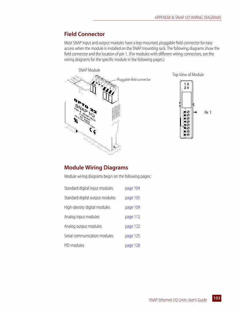
APPENDIX B: SNAP I/O WIRING DIAGRAMS
SNAP Ethernet I/O Units User’s Guide 103103
Field Connector
Most SNAP input and output modules have a top-mounted, pluggable field connector for easy access when the module is installed on the SNAP mounting rack. The following diagrams show the field connector and the location of pin 1. (For modules with different wiring connectors, see the wiring diagrams for the specific module in the following pages.)
Module Wiring Diagrams
Module wiring diagrams begin on the following pages:
Standard digital input modules page 104
Standard digital output modules page 105
High-density digital modules page 109
Analog input modules page 112
Analog output modules page 122
Serial communication modules page 125
PID modules page 128
Pluggable field connector
SNAP ModuleTop View of Module

SNAP I/O MODULES
SNAP Ethernet I/O Units User’s Guide104
Standard Digital Input Modules
For high-density digital modules, see page 109.
Wiring for most standard digital input modules (except SNAP-IDC5-SW and SNAP-IDC5-SW-NC)
Wiring for SNAP-IDC5-SW and SNAP-IDC5-SW-NC digital input modules
CAUTION: The SNAP-IDC5-SW and SNAP-IDC5-SW-NC inputs are not intended to be used with contacts that are connected to any external user-supplied voltage or currents.

APPENDIX B: SNAP I/O WIRING DIAGRAMS
SNAP Ethernet I/O Units User’s Guide 105105
Standard Digital Output Modules
For high-density digital modules, see page 109.
Wiring for SNAP-OAC5 and SNAP-OAC5FM digital AC output modules
Wiring for SNAP-OAC5MA and SNAP-OAC5-i digital AC output modules
NOTE: Each output should be fused.
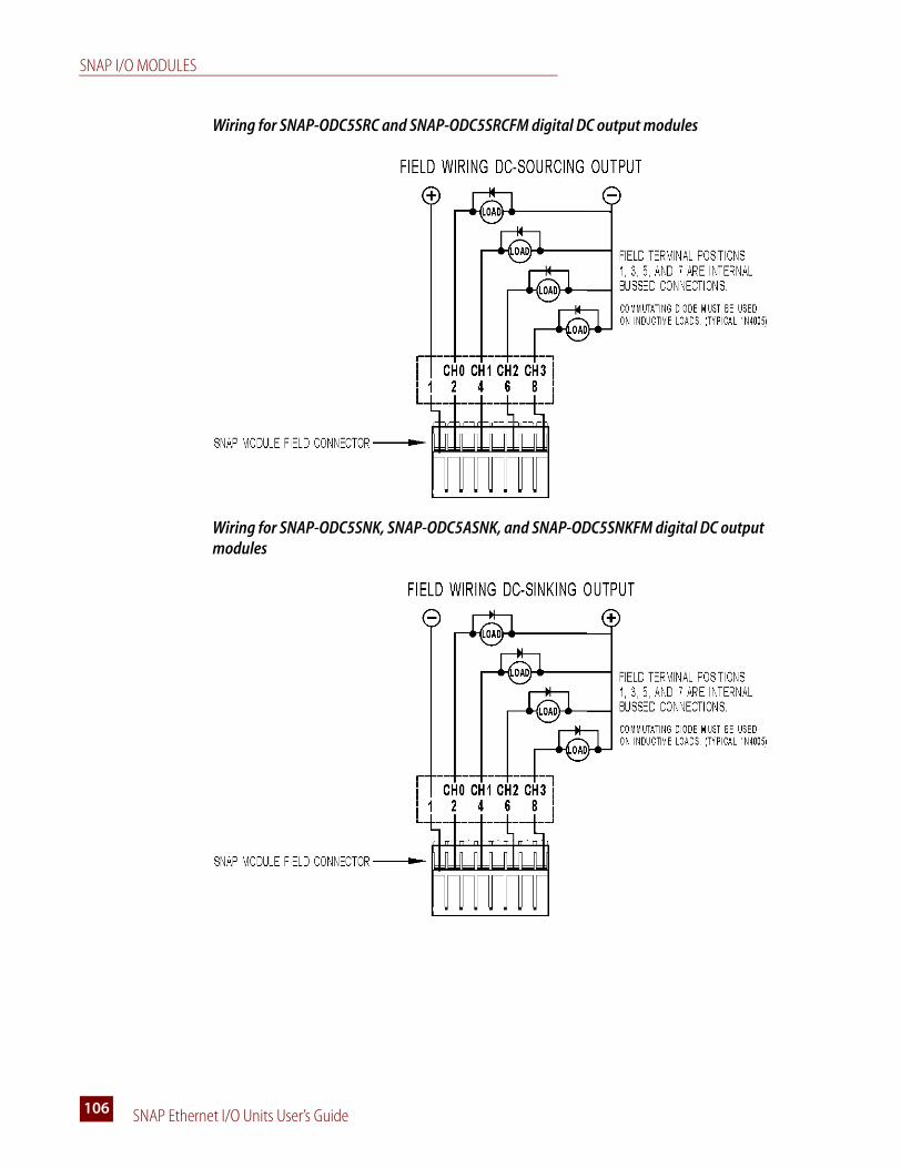
SNAP I/O MODULES
SNAP Ethernet I/O Units User’s Guide106
Wiring for SNAP-ODC5SRC and SNAP-ODC5SRCFM digital DC output modules
Wiring for SNAP-ODC5SNK, SNAP-ODC5ASNK, and SNAP-ODC5SNKFM digital DC output modules
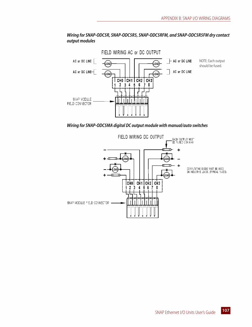
APPENDIX B: SNAP I/O WIRING DIAGRAMS
SNAP Ethernet I/O Units User’s Guide 107107
Wiring for SNAP-ODC5R, SNAP-ODC5R5, SNAP-ODC5RFM, and SNAP-ODC5R5FM dry contact output modules
Wiring for SNAP-ODC5MA digital DC output module with manual/auto switches
NOTE: Each output should be fused.
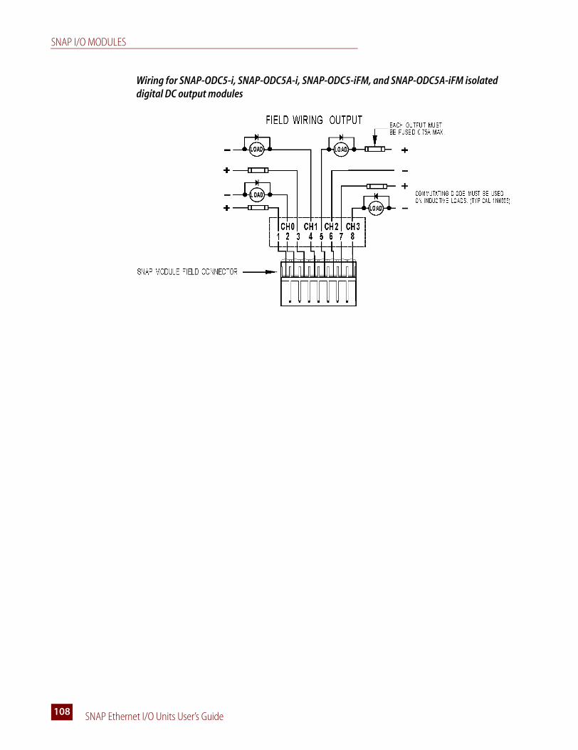
SNAP I/O MODULES
SNAP Ethernet I/O Units User’s Guide108
Wiring for SNAP-ODC5-i, SNAP-ODC5A-i, SNAP-ODC5-iFM, and SNAP-ODC5A-iFM isolated digital DC output modules
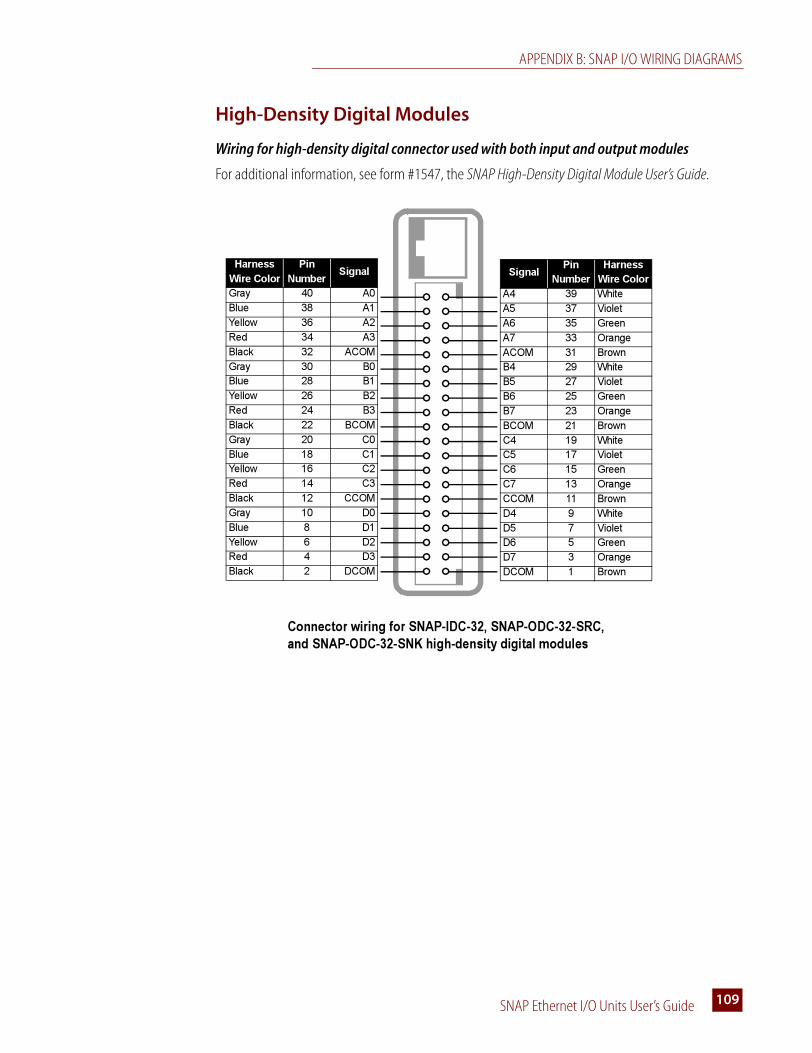
APPENDIX B: SNAP I/O WIRING DIAGRAMS
SNAP Ethernet I/O Units User’s Guide 109109
High-Density Digital Modules
Wiring for high-density digital connector used with both input and output modules
For additional information, see form #1547, the SNAP High-Density Digital Module User’s Guide.
Signal
Pin
Number
Harness
Wire Color
A4 39 White
A5 37 Violet
A6 35 Green
A7 33 Orange
ACOM 31 Brown
B4 29 White
B5 27 Violet
B6 25 Green
B7 23 Orange
BCOM 21 Brown
C4 19 White
C5 17 Violet
C6 15 Green
C7 13 Orange
CCOM 11 Brown
D4 9 White
D5 7 Violet
D6 5 Green
D7 3 Orange
DCOM 1 Brown
Harness
Wire Color
Pin
Number
Signal
Gray 40 A0
Blue 38 A1
Yellow 36 A2
Red 34 A3
Black 32 ACOM
Gray 30 B0
Blue 28 B1
Yellow 26 B2
Red 24 B3
Black 22 BCOM
Gray 20 C0
Blue 18 C1
Yellow 16 C2
Red 14 C3
Black 12 CCOM
Gray 10 D0
Blue 8 D1
Yellow 6 D2
Red 4 D3
Black 2 DCOM
Connector wiring for SNAP-IDC-32, SNAP-ODC-32-SRC,
and SNAP-ODC-32-SNK high-density digital modules
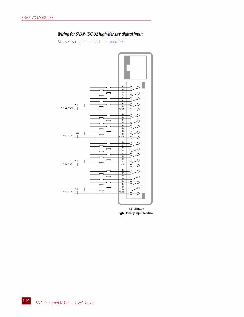
SNAP I/O MODULES
SNAP Ethernet I/O Units User’s Guide110
Wiring for SNAP-IDC-32 high-density digital input
Also see wiring for connector on page 109.
B0
B4
B1
B5
B2
B6
B3
B7
BCOM
10–32 VDC
C0
C4
C1
C5
C2
C6
C3
C7
CCOM10–32 VDC
D0
D4
D1
D5
D2
D6
D3
D7
DCOM10–32 VDC
A0
A4
A1
A5
A2
A6
A3
A7
ACOM
+
10–32 VDC
+
+
+
SNAP-IDC-32
High-Density Input Module

APPENDIX B: SNAP I/O WIRING DIAGRAMS
SNAP Ethernet I/O Units User’s Guide 111111
Wiring for SNAP-ODC-32-SNK and SNAP-ODC-32-SRC high-density digital outputs
Also see wiring for connector on page 109.
B0
B4
B1
B5
B2
B6
B3
B7
BCOM
12–24 VDC
C0
C4
C1
C5
C2
C6
C3
C7
CCOM
12–24 VDC
D0
D4
D1
D5
D2
D6
D3
D7
DCOM
12–24 VDC
A0
A4
A1
A5
A2
A6
A3
A7
ACOM+
12–24 VDC
+
+
+
B0
B4
B1
B5
B2
B6
B3
B7
BCOM
12–24 VDC
C0
C4
C1
C5
C2
C6
C3
C7
CCOM
12–24 VDC
D0
D4
D1
D5
D2
D6
D3
D7
DCOM
12–24 VDC
A0
A4
A1
A5
A2
A6
A3
A7
ACOM
+
12–24 VDC
LOAD
LOA
LOA
LOA
LOA
LOA
LOA
LOA
LOA
LOA
LOA
LOA
LOA
LOA
LOA
LOA
LOA
LOA
LOA
LOA
LOA
LOA
LOA
LOA
LOA
LOA
LOA
LOA
LOA
LOA
LOA
LOA
SNAP-ODC-32-SRC
Load Sourcing Module
SNAP-ODC-32-SNK
Load Sinking Module
+
+
+
LOAD
LOAD
LOAD
LOAD
LOAD
LOAD
LOAD
LOAD
LOA
LOA
LOA
LOA
LOA
LOA
LOA
LOAD
LOAD
LOAD
LOAD
LOAD
LOAD
LOAD
LOA
LOA
LOA
LOA
LOA
LOA
LOA
LOA
LOAD
LOA
LOA
LOA
LOA
LOA
LOA
LOA
LOAD
LOAD
LOAD
LOAD
LOAD
LOAD
LOAD
LOA
LOA
LOA
LOA
LOA
LOA
LOA
LOA
LOA
LOA
LOA
LOA
LOA
LOA
LOA
LOA
LOAD
LOA
LOA
LOA
LOA
LOA
LOA
LOA
LOAD
LOAD
LOAD
LOAD
LOAD
LOAD
LOAD
LOAD
LOA
LOA
LOA
LOA
LOA
LOA
LOA
LOA
LOA
LOA
LOA
LOA
LOA
LOA
LOA
LOA
LOA
LOA
LOA
LOA
LOA
LOA
LOA
LOA
LOA
LOA
LOA
LOA
LOA
LOA
LOA
LOAD
LOAD
LOAD
LOAD
LOAD
LOAD
LOAD
LOAD
LOA
LOA
LOA
LOA
LOA
LOA
LOA
LOAD
LOAD
LOAD
LOAD
LOAD
LOAD
LOAD
LOA
LOA
LOA
LOA
LOA
LOA
LOA
LOA
LOAD
LOA
LOA
LOA
LOA
LOA
LOA
LOA
LOAD
LOAD
LOAD
LOAD
LOAD
LOAD
LOAD
LOA
LOA
LOA
LOA
LOA
LOA
LOA
LOA
LOA
LOA
LOA
LOA
LOA
LOA
LOA
LOA
LOAD
LOA
LOA
LOA
LOA
LOA
LOA
LOA
LOAD
LOAD
LOAD
LOAD
LOAD
LOAD
LOAD
FUSING
For both sourcing and sinking
modules, use one of the two
fusing options shown in the
first two output groups below.

SNAP I/O MODULES
SNAP Ethernet I/O Units User’s Guide112
Analog Input Modules
Wiring for SNAP-AIARMS analog amps RMS AC/DC input
Wiring for SNAP-AIARMS-i isolated analog amps RMS AC/DC input
Two possible wiring diagrams are shown. Terminals 3, 4, 7, and 8 share a common connection inside the module. Make sure you observe polarity when connecting the second channel. To avoid a potentially hazardous short, double-check wiring before turning on the current to be monitored.
Two possible wiring diagrams are shown. The module’s two points are isolated from each other.
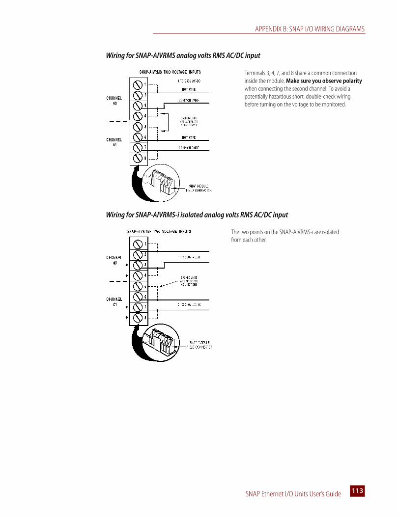
APPENDIX B: SNAP I/O WIRING DIAGRAMS
SNAP Ethernet I/O Units User’s Guide 113113
Wiring for SNAP-AIVRMS analog volts RMS AC/DC input
Wiring for SNAP-AIVRMS-i isolated analog volts RMS AC/DC input
Terminals 3, 4, 7, and 8 share a common connection inside the module. Make sure you observe polarity when connecting the second channel. To avoid a potentially hazardous short, double-check wiring before turning on the voltage to be monitored.
The two points on the SNAP-AIVRMS-i are isolated from each other.
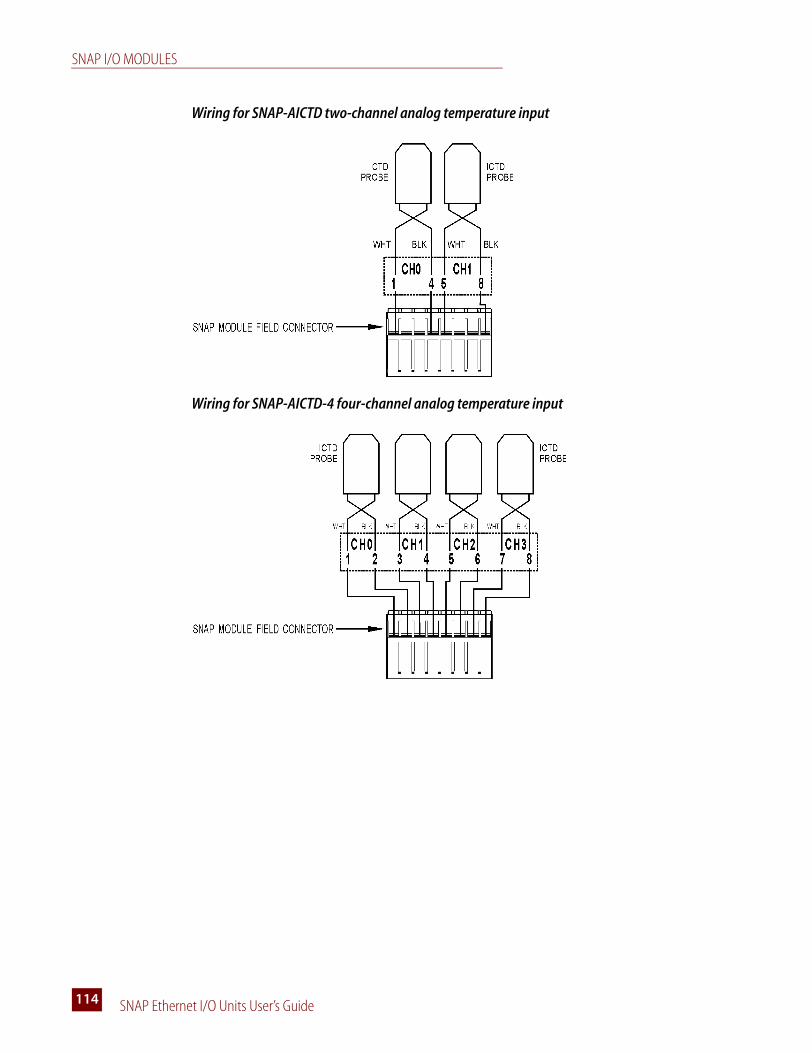
SNAP I/O MODULES
SNAP Ethernet I/O Units User’s Guide114
Wiring for SNAP-AICTD two-channel analog temperature input
Wiring for SNAP-AICTD-4 four-channel analog temperature input

APPENDIX B: SNAP I/O WIRING DIAGRAMS
SNAP Ethernet I/O Units User’s Guide 115115
Wiring for SNAP-AILC load cell input
Wiring for SNAP-AIMA two-channel analog current input
Since all inputs share a common reference, the module must be installed at the beginning or end of a typical 4–20 mA loop. If you are using both standard and self-sourcing transmitters, either put the transmitters on different modules, or use different power supplies. Do not use standard and self-sourcing transmitters on the same module.This module does NOT supply loop excitation current.

SNAP I/O MODULES
SNAP Ethernet I/O Units User’s Guide116
Wiring for SNAP-AIMA-4 four-channel analog current input
Wiring for SNAP-AIMA-i and SNAP-AIMA2-i isolated two-channel analog current inputs
Since all inputs share a common reference, the module must be installed at the beginning or end of a typical 4–20 mA loop. If you are using both standard and self-sourcing transmitters, either put the transmitters on different modules, or use different power supplies. Do not use standard and self-sourcing transmitters on the same module.This module does NOT supply loop excitation current.
The two channels are isolated from each other. This module does NOT supply loop excitation current.
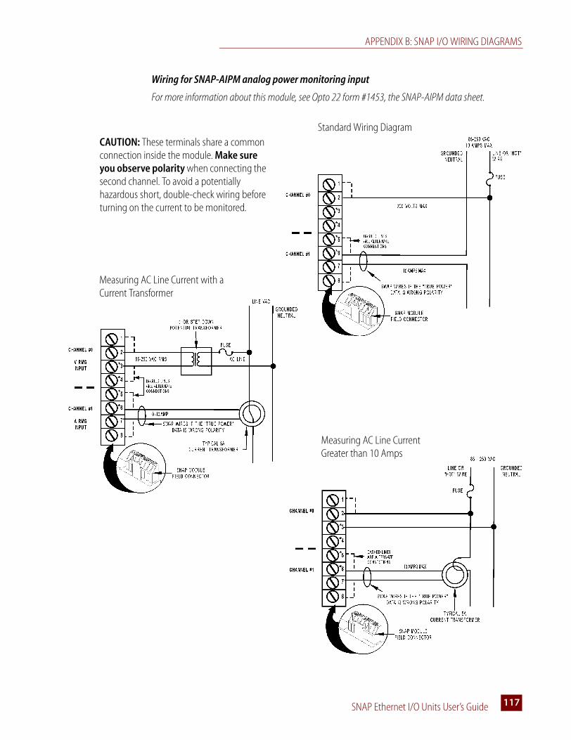
APPENDIX B: SNAP I/O WIRING DIAGRAMS
SNAP Ethernet I/O Units User’s Guide 117117
Wiring for SNAP-AIPM analog power monitoring input
For more information about this module, see Opto 22 form #1453, the SNAP-AIPM data sheet.
Standard Wiring Diagram
Measuring AC Line Current with a Current Transformer
Measuring AC Line Current Greater than 10 Amps
CAUTION: These terminals share a common connection inside the module. Make sure you observe polarity when connecting the second channel. To avoid a potentially hazardous short, double-check wiring before turning on the current to be monitored.

SNAP I/O MODULES
SNAP Ethernet I/O Units User’s Guide118
Wiring for SNAP-AIMA-iSRC isolated two-channel analog current input
Wiring for SNAP-AIR40K-4 analog thermistor input
The two channels are isolated from each other. This module DOES supply loop excitation current.

APPENDIX B: SNAP I/O WIRING DIAGRAMS
SNAP Ethernet I/O Units User’s Guide 119119
Wiring for SNAP-AIRATE analog rate input
Wiring for SNAP-AIMV-4 and AIMV2-4 analog millivolt inputs
Wiring for SNAP-AITM and SNAP-AITM-2 analog thermocouple/millivolt inputs
Two possible wiring diagrams are shown:
Since both inputs share the same reference terminal, use isolated probes for thermocouple inputs.

SNAP I/O MODULES
SNAP Ethernet I/O Units User’s Guide120
Wiring for SNAP-AITM-i and SNAP-AITM-2-i isolated analog thermocouple/millivolt inputs
Wiring for SNAP-AIRTD analog RTD input
Wiring for SNAP-AIV two-channel analog voltage input
Since these channels do not share any common connections, grounded sensors and field devices may be used with them.
The SNAP-AIRTD is designed for three-wire connections, shown in the diagram at right.

APPENDIX B: SNAP I/O WIRING DIAGRAMS
SNAP Ethernet I/O Units User’s Guide 121121
Wiring for SNAP-AIV-4 four-channel analog voltage input
Wiring for SNAP-AIV-i and SNAP-AIV2-i isolated two-channel analog voltage input
The two channels are isolated from each other. Since these channels do not share any common connections, grounded sensors and field devices may be used with them.

SNAP I/O MODULES
SNAP Ethernet I/O Units User’s Guide122
Analog Output Modules
Wiring for the SNAP-AOA-3 single-channel analog current output
Wiring for the SNAP-AOV-5 single-channel analog voltage outputs

APPENDIX B: SNAP I/O WIRING DIAGRAMS
SNAP Ethernet I/O Units User’s Guide 123123
Wiring for the SNAP-AOA-23 dual-channel analog current output
Wiring for the SNAP-AOA-23-iSRC isolated dual-channel analog current output
Both channels share a common reference terminal.
The module includes built-in loop sourcing capability. The two channels and their loop sources are isolated from each other.

SNAP I/O MODULES
SNAP Ethernet I/O Units User’s Guide124
Wiring for the SNAP-AOA-25 and SNAP-AOA-27 dual-channel analog voltage output
Wiring for the SNAP-AOA-28 dual-channel analog current output
Both channels share a common reference terminal.
Both channels share a common reference terminal.
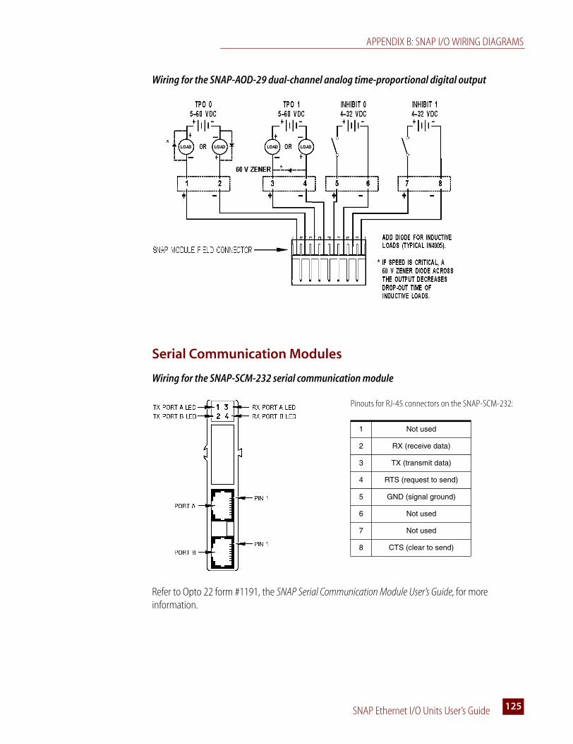
APPENDIX B: SNAP I/O WIRING DIAGRAMS
SNAP Ethernet I/O Units User’s Guide 125125
Wiring for the SNAP-AOD-29 dual-channel analog time-proportional digital output
Serial Communication Modules
Wiring for the SNAP-SCM-232 serial communication module
Refer to Opto 22 form #1191, the SNAP Serial Communication Module User’s Guide, for more information.
Pinouts for RJ-45 connectors on the SNAP-SCM-232:
1 Not used
2 RX (receive data)
3 TX (transmit data)
4 RTS (request to send)
5 GND (signal ground)
6 Not used
7 Not used
8 CTS (clear to send)
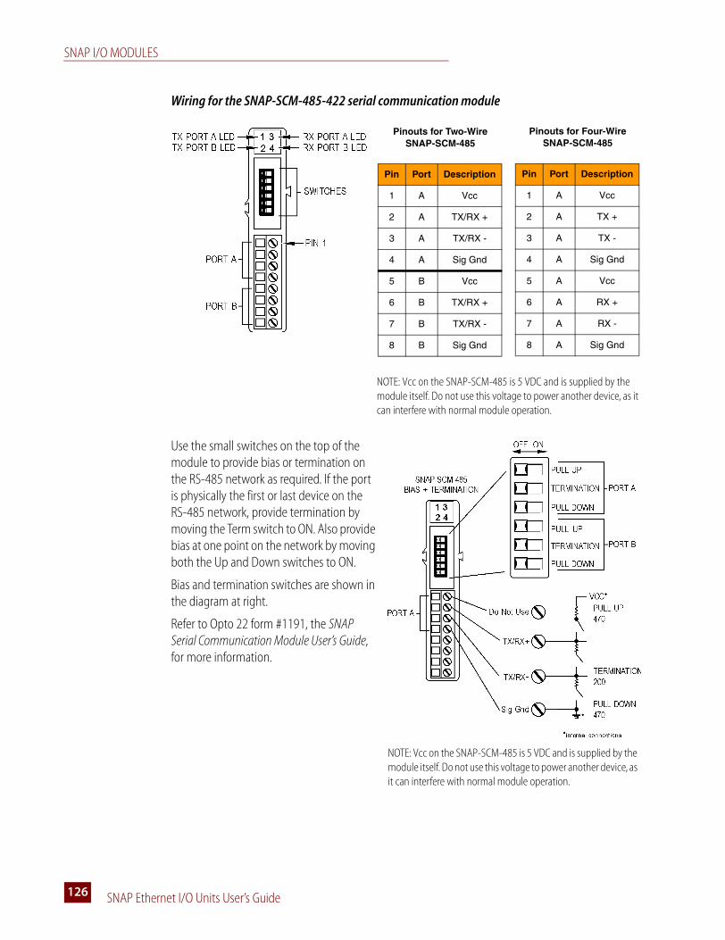
SNAP I/O MODULES
SNAP Ethernet I/O Units User’s Guide126
Wiring for the SNAP-SCM-485-422 serial communication module
Use the small switches on the top of the module to provide bias or termination on the RS-485 network as required. If the port is physically the first or last device on the RS-485 network, provide termination by moving the Term switch to ON. Also provide bias at one point on the network by moving both the Up and Down switches to ON.
Bias and termination switches are shown in the diagram at right.
Refer to Opto 22 form #1191, the SNAP Serial Communication Module User’s Guide, for more information.
NOTE: Vcc on the SNAP-SCM-485 is 5 VDC and is supplied by the module itself. Do not use this voltage to power another device, as it can interfere with normal module operation.
Pinouts for Two-Wire SNAP-SCM-485
Pin Port Description
1 A Vcc
2 A TX/RX +
3 A TX/RX -
4 A Sig Gnd
5 B Vcc
6 B TX/RX +
7 B TX/RX -
8 B Sig Gnd
Pinouts for Four-Wire SNAP-SCM-485
Pin Port Description
1 A Vcc
2 A TX +
3 A TX -
4 A Sig Gnd
5 A Vcc
6 A RX +
7 A RX -
8 A Sig Gnd
NOTE: Vcc on the SNAP-SCM-485 is 5 VDC and is supplied by the module itself. Do not use this voltage to power another device, as it can interfere with normal module operation.

APPENDIX B: SNAP I/O WIRING DIAGRAMS
SNAP Ethernet I/O Units User’s Guide 127127
Wiring for the SNAP-SCM-PROFI serial communication module
Communication switches are shown in the diagram at right. If you are using an official PROFIBUS cable, termination is provided in the cable; therefore, switch the termination to ON in the cable and move the Term switch to OFF in the SNAP-SCM-PROFI module.
See the SNAP Serial Communication Module User’s Guide (form #1191) for more information.
Wiring for the SNAP-SCM-W2 serial communication module
NOTE: Use with SNAP PAC R-series, SNAP Ethernet, or SNAP Ultimate only.
SNAP-SCM-PROFI Top View
Switches
PowerReceive
RunTransmit
OFF ON
Pull Up ResistorPull Down ResistorTermination
Not UsedSerial Port
Communication
Pinouts for SNAP-SCM-W2
Pin Port Color Description
1 A Black Common
2 A White Data One
3 A Green Data Zero
4 A -- Not used
5 B Black Common
6 B White Data One
7 B Green Data Zero
8 B -- Not used
SNAP-SCM-W2 Top View
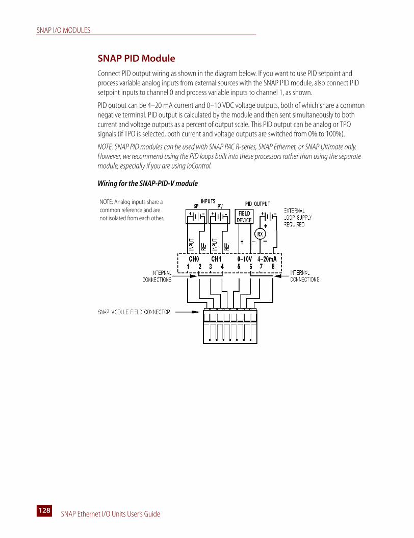
SNAP I/O MODULES
SNAP Ethernet I/O Units User’s Guide128
SNAP PID Module
Connect PID output wiring as shown in the diagram below. If you want to use PID setpoint and process variable analog inputs from external sources with the SNAP PID module, also connect PID setpoint inputs to channel 0 and process variable inputs to channel 1, as shown.
PID output can be 4–20 mA current and 0–10 VDC voltage outputs, both of which share a common negative terminal. PID output is calculated by the module and then sent simultaneously to both current and voltage outputs as a percent of output scale. This PID output can be analog or TPO signals (if TPO is selected, both current and voltage outputs are switched from 0% to 100%).
NOTE: SNAP PID modules can be used with SNAP PAC R-series, SNAP Ethernet, or SNAP Ultimate only. However, we recommend using the PID loops built into these processors rather than using the separate module, especially if you are using ioControl.
Wiring for the SNAP-PID-V module
NOTE: Analog inputs share a common reference and are not isolated from each other.

ioManager User’s Guide 129129
Index
Aaccessing I/O unit over the Internet, 23analog input modules
power requirements, 95troubleshooting, 67wiring, 112
analog output modulespower requirements, 95troubleshooting, 67wiring, 122
analog point features, 39analog/digital brain
configuring points for Modbus, 77Modbus function codes supported, 70, 71
average filter weight, 40
Bbackup battery, 43battery, 43blink codes, 61brain
feature comparison chart, 37installing, 10, 100power requirements, 95rack compatibility, 92Scratch Pad, 29, 42specifications, 35
Ccable
crossover, 32
straight-through, 32changing
IP address, 43clamping, 40coils (Modbus), 82, 87, 90communicating with brain, 21
peer-to-peer, 29pinging the brain, 58problems with, 57simultaneously, 22via modem, 17
communicationchoosing methods, 23serial, 40with enterprise systems, 30
communication packetfor Modbus/TCP, 71
computer, connecting directly to brain, 32configuring
I/O pointsfor Modbus/TCP, 77, 79
modem communication, 12PPP, 12
connectingmodem, 17to brain, troubleshooting, 57to the enterprise, 30
control side of Ultimate brain, 26control strategy, 27controller
installing, 100power requirements, 95rack compatibility, 92

ioManager User’s Guide130
controller, sharing data with, 29controlling multiple I/O units, 28copying memory map data, 41counter
high-speed, 39Modbus/TCP, 80quadrature, 39
crossover cable, 32current loop power supply, wiring, 97
Ddata
copying, 41delivering to databases, 30logging, 41mirroring, 41Modbus float format, 81sharing among Ultimate I/O units, 29streaming, 42
default settings for brain, 50dial-up networking
configuring, 12on Windows 2000, 17
digital input modulespower requirements, 95troubleshooting, 65wiring, high-density, 109wiring, standard, 104
digital output modulespower requirements, 95troubleshooting, 65wiring, high-density, 109wiring, standard, 105
digital point features, 39direct connection, 32downloading
see loading
Eemail, 30, 41enterprise connectivity, 30enterprise management system, 30, 42error codes
blink codes, 61
Modbus/TCP exception errors, 72Ethernet network
accessing I/O unit over the Internet, 23certification, 61connecting brain to, 33errors, 60independent control network, 34troubleshooting, 60
event messages, 41events, 41exception code, Modbus/TCP, 72
Ffactory default settings, 50features
comparison chart for brains, 37descriptions, 39
filter weight, 40finding out IP address, 48firmware
getting data about, 64loading to controller, 51loading to I/O unit, 51
float format, Modbus, 81flowcharts, 27format
of Modbus float, 81of Modbus/TCP communication packet, 71
Ggain, 40
Modbus/TCP, 81
Hhardware
getting data about, 64help
blink codes, 61LED descriptions, 35network problems, 60Product Support, 5troubleshooting, 57
high-density digital connector, 109

:
ioManager User’s Guide 131131
high-density digital modulespower requirements, 95wiring, 109
high-speed counters, 39holding registers (Modbus), 84, 89
II/O modules
analog input, 112analog output, 122basic diagram, 101high-density digital, 109installing, 8PID, 128power requirements, 95removing, 9serial, 125standard digital input, 104standard digital output, 105troubleshooting, 65
I/O pointfeatures, 37, 39
Modbus/TCP, 79referencing for Modbus/TCP, 73, 75, 76
I/O side of Ultimate brain, 26inputs (Modbus), 83, 88installing
brain on rack, 10I/O modules, 8, 101I/O unit (quick start), 7modem, 17mounting rack, 8, 92power supplies, 94processor on rack, 100
Internet, accessing I/O unit over, 23ioControl, 27ioDisplay, 28ioManager, 4IP address
changing, 43resetting to factory default, 50viewing, 43, 48
IP filtering, 42
Jjumpers, 62
Kkernel mode, 62kernel, see firmware
Llatches, 39
Modbus/TCP, 80LEDs
blink codes, 61description, 35red, 57
Linux, 3loader mode, 62loading
new firmware to I/O unit or controller, 51logging data, 41loop power supply, 97
Mmaximum value, 40
Modbus/TCP, 81memory map, 27, 29
copying data, 41Modbus
analog/digital brains, 82analog/simple digital brains, 87digital-only brains, 90
minimum value, 40Modbus/TCP, 81
mirroring data, 41Modbus float format, 81Modbus/TCP, 30
communication packet, 71configuring I/O points
for analog/digital brains, 77for digital-only brains, 79
counters, 80exception errors, 72function codes supported, 70latches, 80

ioManager User’s Guide132
memory mapanalog/digital brains, 82analog/simple digital brains, 87digital-only brains, 90
minimum/maximum values, 81offset and gain, 81point configuration examples, 79scaling, 81
modem, 42connecting to brain, 17using PPP, 12
mounting rackinstalling, 8wiring, 92
Nnetwork
architecture, 32certification, 61Ethernet errors, 60independent, 34modem communication, 34OptoEnetSniff, 61troubleshooting, 60
NVRAM, 17
Ooffset, 40
Modbus/TCP, 81OPC, 4, 30Opto 22 Product Support, 5OptoEnetSniff, 61output clamping, 40
Ppacket for Modbus/TCP, 71peer-to-peer communication, 29PID loops, 41PID modules
power requirements, 95wiring, 128
ping, 58point-to-point protocol, 42
port access, limiting, 42power monitoring module, 117power supply
current loop, 97determining requirements, 95wiring, 94
PPP, 34, 42configuring, 12
problems, troubleshooting, 57processor
installing, 100power requirements, 95rack compatibility, 92
Product Support, 5getting device and firmware data, 64
Qquadrature counters, 39quick start, 7
Rrack for I/O modules
compatibility, 92installing, 8wiring, 92
readingIP address, 48IP address and subnet mask, 43
registers (Modbus), 83, 88removing I/O modules, 9replacing backup battery, 43resetting brain to factory defaults, 50retransmit timeout (RTO), 62
Sscaling, 40
Modbus/TCP, 81Scratch Pad areas, 29, 42security, 42serial communication, 40serial connection to brain, diagram, 46, 48, 56serial modules
power requirements, 95

:
ioManager User’s Guide 133133
wiring, 125sharing data among Ultimate I/O units, 29SMTP, 30SNAP Ultimate brain
diagram, 26memory map, 27, 29Scratch Pad area, 29
SNAP-AIARMS, 112SNAP-AIARMS-i, 112SNAP-AICTD, 114SNAP-AICTD-4, 114SNAP-AILC, 115SNAP-AIMA, 115SNAP-AIMA2-i, 116SNAP-AIMA-4, 116SNAP-AIMA-i, 116SNAP-AIMA-iSRC, 118SNAP-AIMV2-4, 119SNAP-AIMV-4, 119SNAP-AIPM, 117SNAP-AIR40K-4, 118SNAP-AIRATE, 119SNAP-AIRTD, 120SNAP-AITM, 119SNAP-AITM-2, 119SNAP-AITM-2-i, 120SNAP-AITM-i, 120SNAP-AIV, 120SNAP-AIV2-i, 121SNAP-AIV-4, 121SNAP-AIV-i, 121SNAP-AIVRMS, 113SNAP-AIVRMS-i, 113SNAP-AOA-23, 123SNAP-AOA-23-iSRC, 123SNAP-AOA-25, 124SNAP-AOA-27, 124SNAP-AOA-28, 124SNAP-AOA-3, 122SNAP-AOD-29, 125SNAP-AOV-5, 122SNAP-ENET-RTC brain, replacement battery, 43SNAP-IDC-32, 110SNAP-IDC5-SW, 104SNAP-IDC5-SW-NC, 104
SNAP-OAC5, 105SNAP-OAC5FM, 105SNAP-OAC5-i, 105SNAP-OAC5MA, 105SNAP-ODC-32-SNK, 111SNAP-ODC-32-SRC, 111SNAP-ODC5A-i, 108SNAP-ODC5A-iFM, 108SNAP-ODC5ASNK, 106SNAP-ODC5-i, 108SNAP-ODC5-iFM, 108SNAP-ODC5MA, 107SNAP-ODC5R, 107SNAP-ODC5R5, 107SNAP-ODC5R5FM, 107SNAP-ODC5RFM, 107SNAP-ODC5SNK, 106SNAP-ODC5SNKFM, 106SNAP-ODC5SRC, 106SNAP-ODC5SRCFM, 106SNAP-PID-V, 128SNAP-SCM-232, 125SNAP-SCM-485, 126SNAP-SCM-PROFI, 127SNAP-SCM-W2, 127SNMP, 30, 42specifications, 35straight-through cable, 32strategy, 27streaming data, 42subnet mask, 43system architecture, 32
TTCP/IP
multiple sessions, 22settings, 62stack, 62
technical support, 5third-party software, 30timeout, 62timers, 41troubleshooting, 57
analog I/O modules, 67blink codes, 61

ioManager User’s Guide134
digital I/O modules, 65LED descriptions, 35Modbus exception errors, 72network, 60Product Support, 5
UUDP and streaming data, 42
Ultimate braindiagram, 26memory map, 27, 29Scratch Pad area, 29
utilitiesOptoEnetSniff, 61
Wwatchdog, 39, 40