SMU ENSIGN® CAST IRON DRAINAGE SYSTEMS
120
Comprehensive pipe solutions SMU ENSIGN ® CAST IRON DRAINAGE SYSTEMS 2015 Version
Transcript of SMU ENSIGN® CAST IRON DRAINAGE SYSTEMS
Comprehensive pipe solutions
S M U E N S I G N ®
C A S T I R O N D R A I N A G E
S Y S T E M S2 0 1 5 V e r s i o n
SummaryPage(s)
Section 1: Sales28 arguments 3
Why choose SAINT-GOBAIN PAM cast iron pipe systems 4-5
Modular product range 6-7Ability to transport effluents 8-9Characterisation of common domestic applications 10Recommendations 11Characterisation of intense or professional uses 12Recommendations 13Characterisation of external stresses and recommendations 14-15Robustness and mechanical stress 16Resistance to thermal expansion 17Water tightness 18Internal pressure resistance 19Ageing behaviour 20Compliance with standards and Quality marks 21Fire safety 22-23Acoustics 24-25Environment 26-27EPAMS syphonic system 28-29Total cost of ownership 30
Section 2: Products catalogue 31PAM SMU / ENSIGN SProducts identification – S ranges 32Pipes 33Bends 34-35Branches 36-37Double branches 38-39Long fittings 40-41Connectors 42Access fittings / Plugs 43Traps and ventilation 44-45Special fittings 46-47Compensators of movement 48PUSH-FIT ranges 49SME range 50-51EEZI-FIT 52-53
PAM SMU / ENSIGN PlusProducts identification –Plus ranges 54Pipes 55Bends 56-57Branches 58-59Double branches 60-61Branches / plug 62Traps/Access 63Reducer 64Couplings and Grip collars 65-73Connectors 74-75Bracketing 76-79Syphonic system EPAMS / roof outlets 80-83
General terms and conditions of sales 84-85
Page(s)
Section 3: Specifier’s Manual 87
Installation features 88Modifications to an existing installation 89Jointing methods –Stainless steel couplings 90-91Couplings technical features 92Couplings + grip collars: performance level 93Jointing methods –Ductile iron couplings 94Push-fit systems 95Connection to other materials 96-99Requirements and permissible pressure load 100-101Ventilation & Roof penetration device 102-103Multi waste manifold 104Single stack branch 105Pipework stability 106Access to the pipework 107Bracketing: technical 108-110Cast iron protection 111Buried pipe systems 112-113EPAMS syphonic roof drainage pipeworks 114-115Standards specifications 116-117Discharge capability 118Commercial references 119
PAM Cast iron - 3
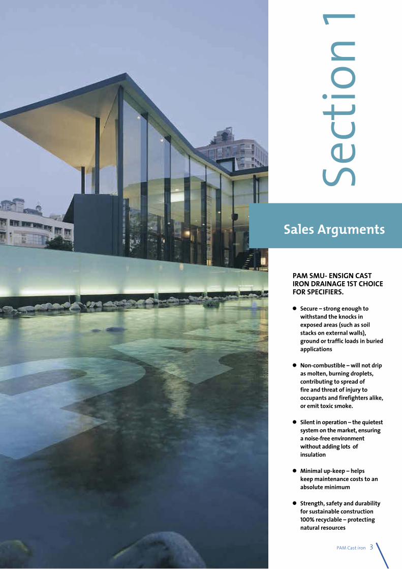
PAM SMU- ENSIGN CAST IRON DRAINAGE 1ST CHOICE FOR SPECIFIERS.
l Secure – strong enough to withstand the knocks in exposed areas (such as soil stacks on external walls), ground or traffic loads in buried applications
l Non-combustible – will not drip as molten, burning droplets, contributing to spread of fire and threat of injury to occupants and firefighters alike, or emit toxic smoke.
l Silent in operation – the quietest system on the market, ensuring a noise-free environment without adding lots of insulation
l Minimal up-keep – helps keep maintenance costs to an absolute minimum
l Strength, safety and durability for sustainable construction 100% recyclable – protecting natural resources
Sales Arguments
Sect
ion 1
4 - PAM Cast iron
Why choose SAINT-GOBAIN PAM cast iron pipe systems?
As a leading manufacturer and the world’s top-ranking exporter of cast iron pipe systems for building drainage applications, SAINT-GOBAIN PAM is an essential partner for designers of waste water and rainwater drainage systems.The SAINT-GOBAIN PAM cast iron products are safe, easy to install and efficiently meet the requirements of project managers.
Natural materialsCast iron products for building drainage systems are made of an alloy of natural elements: iron, carbon and silicon. Cast iron is a natural product and it is manufactured entirely from recycled raw materials: scrap iron and cast iron which are enhanced by a second melting process. SAINT-GOBAIN PAM cast iron combines the traditional longevity of irons with outstanding technical and mechanical properties which remain stable over time and in all climates. Its robustness limits breakages and damaged supplies and its nature and density confer thermal and acoustic properties guaranteeing safety and comfort in use.
Reliable targeted adviceSound advice and technical assistance are among SAINT-GOBAIN PAM’s strong points. During the preliminary project phase, advising designers to find the most suitable solution for their specific requirements and providing them with all the advice they need to get the best out of the products chosen. This may entail providing information required to draw up a safe and reliable project or - for special applications such as syphonic systems - a design study to optimise the future pipe system’s performance.
The Pipe Activity of the SAINT GOBAIN Group
Sells complete and specified technical solutions for water supply, sewerage,
municipal castings and building drainage.
Complete systems for waste water and rainwater drainage:
More than 200 product lines for pipes from DN 50 to DN 600, 1400 product lines for fittings and accessories and more than
450 product lines for couplings to help the project managers find the relevant solution
for each construction project.
The Pipe Activity in figures:
Sales: 1.6 bn €
Around 10 000 employees and more than 30 facilities throughout the world

Technical and sales service networkTo optimise its customer service, SAINT-GOBAIN PAM offers an integrated network of subsidiaries, agents and distributors which can rely on dynamic and experienced technical sales teams to provide excellent customer support and the feedback required for the constant improvement of products and services. After-sales service is provided by highly versatile staff able to analyse customers’ difficulties and find suitable solutions so that no problem remains unsolved.
Please contact us for details of your nearest SAINT-GOBAIN PAM subsidiary or agent.
An efficient logistic supportThanks to a 150 year experience of export sales throughout the world, SAINT-GOBAIN PAM daily ships a wide range of products to offer complete, operational solutions to its customers wherever they are.
Precision of our industrial facilitiesOffering precise technical solutions calls for regular high-quality production facilities. SAINT GOBAIN PAM endeavours to use the best available technology for its manufacturing operations. Working groups set up at its production plants ensure that the best industrial practices in the Pipe Activity are disseminated between all plants. Processes are fully mastered and automated to manufacture products whose quality is constantly being improved while controlling energy consumption.
PAM Cast iron - 5
Complete, compatible and consistent rangesPipes, couplings, fittings and accessories: SAINT-GOBAIN PAM offers a wide range of products combined with coatings and couplings for the construction of consistent pipe systems, benefiting from the outstanding robust properties of cast iron.
Modular product ranges
6 - PAM Cast iron
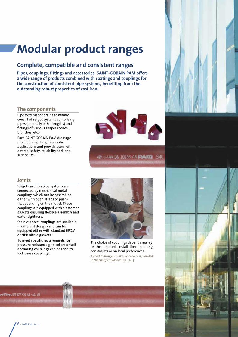
The componentsPipe systems for drainage mainly consist of spigot systems comprising pipes (generally in 3m lengths) and fittings of various shapes (bends, branches, etc.).Each SAINT GOBAIN PAM drainage product range targets specific applications and provide users with optimal safety, reliability and long service life.
The choice of couplings depends mainly on the applicable installation, operating constraints or on local preferences.A chart to help you make your choice is provided in the Specifier’s Manual pp 92-93.
JointsSpigot cast iron pipe systems are connected by mechanical metal couplings which can be assembled either with open straps or push-fit, depending on the model. These couplings are equipped with elastomer gaskets ensuring flexible assembly and water tightness.Stainless steel couplings are available in different designs and can be equipped either with standard EPDM or NBR nitrile gaskets.To meet specific requirements for pressure resistance grip collars or self-anchoring couplings can be used to lock those couplings.
PAM Cast iron - 7
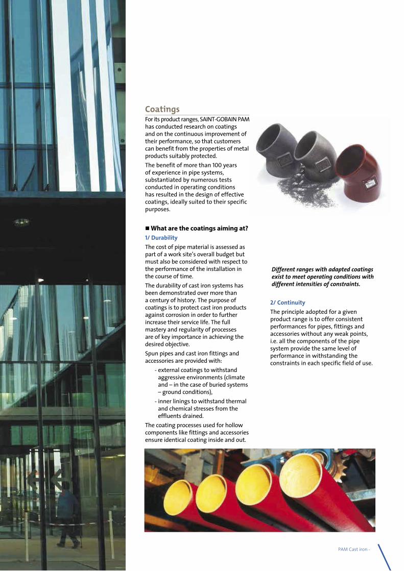
CoatingsFor its product ranges, SAINT-GOBAIN PAM has conducted research on coatings and on the continuous improvement of their performance, so that customers can benefit from the properties of metal products suitably protected.The benefit of more than 100 years of experience in pipe systems, substantiated by numerous tests conducted in operating conditions has resulted in the design of effective coatings, ideally suited to their specific purposes.
What are the coatings aiming at?1/ DurabilityThe cost of pipe material is assessed as part of a work site’s overall budget but must also be considered with respect to the performance of the installation in the course of time.The durability of cast iron systems has been demonstrated over more than a century of history. The purpose of coatings is to protect cast iron products against corrosion in order to further increase their service life. The full mastery and regularity of processes are of key importance in achieving the desired objective.Spun pipes and cast iron fittings and accessories are provided with: - external coatings to withstand
aggressive environments (climate and – in the case of buried systems – ground conditions),
- inner linings to withstand thermal and chemical stresses from the effluents drained.
The coating processes used for hollow components like fittings and accessories ensure identical coating inside and out.
Different ranges with adapted coatings exist to meet operating conditions with different intensities of constraints.
2/ ContinuityThe principle adopted for a given product range is to offer consistent performances for pipes, fittings and accessories without any weak points, i.e. all the components of the pipe system provide the same level of performance in withstanding the constraints in each specific field of use.
Shot blasting RinsingRinsing Hot phosphate process
Rinsing CoolingCataphoresis Oven drying 180 °C
8 - PAM Cast iron
Building waste water drainage systems - grey and black water- must be able to withstand the types of domestic effluents specified by EN 877 standard. In recent years, however, changes have been noticed in the types of these fluids: - Higher concentration of household detergents, - Use of more aggressive hygiene products, - Rise in operating temperatures.The constraints on sanitary drainage systems are constantly increasing. SAINT-GOBAIN PAM coatings have been adapted to meet those constraints.
Ability to transport effluents
Resistance to domestic fluids:
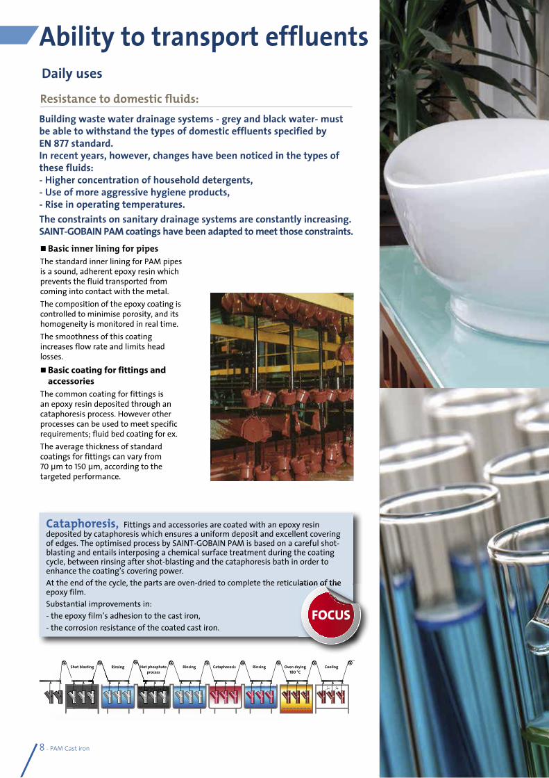
Basic inner lining for pipes The standard inner lining for PAM pipes is a sound, adherent epoxy resin which prevents the fluid transported from coming into contact with the metal.The composition of the epoxy coating is controlled to minimise porosity, and its homogeneity is monitored in real time.The smoothness of this coating increases flow rate and limits head losses. Basic coating for fittings and
accessories The common coating for fittings is an epoxy resin deposited through an cataphoresis process. However other processes can be used to meet specific requirements; fluid bed coating for ex.The average thickness of standard coatings for fittings can vary from 70 μm to 150 μm, according to the targeted performance.
Daily uses
Cataphoresis, Fittings and accessories are coated with an epoxy resin deposited by cataphoresis which ensures a uniform deposit and excellent covering of edges. The optimised process by SAINT-GOBAIN PAM is based on a careful shot-blasting and entails interposing a chemical surface treatment during the coating cycle, between rinsing after shot-blasting and the cataphoresis bath in order to enhance the coating’s covering power.At the end of the cycle, the parts are oven-dried to complete the reticulation of the epoxy film.Substantial improvements in: - the epoxy film’s adhesion to the cast iron,- the corrosion resistance of the coated cast iron.
At the end of the cycle, the parts are oven-dried to complete the reticulation of the
FOCUS
PAM Cast iron - 9
Resistance to corrosive or/and hot effluentsThe inside of cast iron systems can be subjected to chemical and thermal aggressions when they transport fluids that are corrosive and/or at high temperatures. Superior inner lining for pipes: two-part epoxy resin applied in two layers to obtain a film with no porosity.
Resistance to aggressive backfills or severe climatic stressesThe outside of a pipe may also be subjected to the aggressive effects of climate or backfills, in the case of buried systems. External anticorrosion coating for pipes
Zinc coating for pipe protection by galvanic effect.
Solutions for intense stresses on fittings and accessoriesAccording to the principle of continuity with no weak points, coatings for hollow components must withstand the same stresses as pipes. There is an anticorrosion coating process for these parts to face major stresses, due to the fluids transported or to the environment.
For more than 100 years of testing and market research, SAINT GOBAIN PAM has built up great expertise in cast iron. Increasingly effective coatings have been developed to keep pace with the changing utilisations and requirements.
Superior coating for fittings and accessories: epoxy powder coating in fluid bed.A thick anticorrosion coating to guarantee long service life for products.Preheated parts are moved through a tank containing epoxy powder in suspension, to be coated. They are then stove dried to ensure perfect reticulation of the polymerised epoxy film. Perfect control of both temperature and immersion time determines the coating thickness: 300 μm in average.
Intense uses
Zinc metallization The zinc metallization is an active protection provided by the galvanic action of a zinc/iron cell.Twofold action:• Formation of a stable protective layer
of insoluble zinc salts,• Self-healing of any damage.Zinc metallization is an excellent corrosion inhibitor and is extremely effective in extending the lifespan of products submitted to backfills or climatic stresses.
Tests carried out by the SAINT-GOBAIN PAM Research Centre: two identical notches are made on samples before immersing them in a highly corrosive medium.
Without zinc protection Corrosion beyond notch
With zinc protection Zinc salts on notch
FOCUS
© N
orm
an P
ogso
n - F
otol
ia.co
m©
Oliv
ier -
Foto
lia.co
m
10 - PAM Cast iron
Recommended ranges for these applicationsS ranges and socket ranges, SME or EEZI-FIT, equipped with EPDM gaskets are fully adapted to fit all the constraints involved in the above-mentioned uses.S – SME systems: complete ranges of cast iron pipes & fittings and their gaskets.SMU/ ENSIGN spigot range: 11 diameters from DN 50 to DN 600SME, socket range: 5 diameters from DN 50 to DN 150EEZI-FIT: new range of socket fittings and couplings in 100 mm and 150 mm diameter, designed to be quick and simple to assemble for above ground gravity sanitary installations.
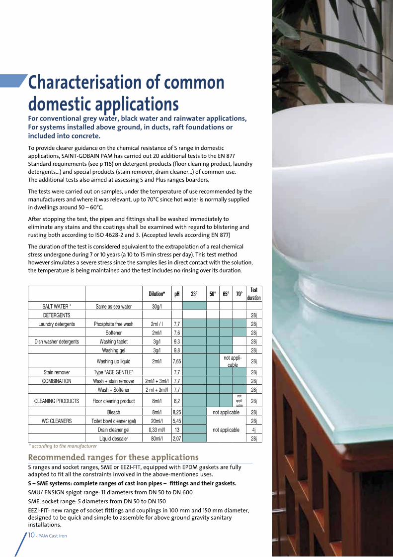
Characterisation of common domestic applications For conventional grey water, black water and rainwater applications, For systems installed above ground, in ducts, raft foundations or included into concrete. To provide clearer guidance on the chemical resistance of S range in domestic applications, SAINT-GOBAIN PAM has carried out 20 additional tests to the EN 877 Standard requirements (see p 116) on detergent products (floor cleaning product, laundry detergents…) and special products (stain remover, drain cleaner…) of common use. The additional tests also aimed at assessing S and Plus ranges boarders.
The tests were carried out on samples, under the temperature of use recommended by the manufacturers and where it was relevant, up to 70°C since hot water is normally supplied in dwellings around 50 – 60°C.
After stopping the test, the pipes and fittings shall be washed immediately to eliminate any stains and the coatings shall be examined with regard to blistering and rusting both according to ISO 4628-2 and 3. (Accepted levels according EN 877)
The duration of the test is considered equivalent to the extrapolation of a real chemical stress undergone during 7 or 10 years (a 10 to 15 min stress per day). This test method however simulates a severe stress since the samples lies in direct contact with the solution, the temperature is being maintained and the test includes no rinsing over its duration.
Dilution* pH 23° 50° 65° 70°Test
durationSALT WATER * Same as sea water 30g/l
DETERGENTS 28j
Laundry detergents Phosphate free wash 2ml / l 7,7 28j
Softener 2ml/l 7,6 28j
Dish washer detergents Washing tablet 3g/l 9,3 28j
Washing gel 3g/l 9,8 28j
Washing up liquid 2ml/l 7,65not appli-
cable28j
Stain remover Type “ACE GENTLE” 7,7 28j
COMBINATION Wash + stain remover 2ml/l + 3ml/l 7,7 28j
Wash + Softener 2 ml + 3ml/l 7,7 28j
CLEANING PRODUCTS Floor cleaning product 8ml/l 8,2not
appli-cable
28j
Bleach 8ml/l 8,25 not applicable 28j
WC CLEANERS Toilet bowl cleaner (gel) 20ml/l 5,45
not applicable
28j
Drain cleaner gel 0,33 ml/l 13 4j
Liquid descaler 80ml/l 2,07 28j* according to the manufacturer
PAM Cast iron - 11
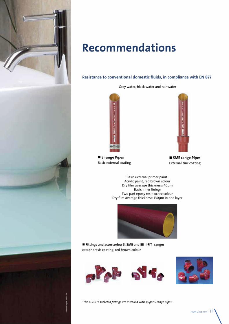
S range Pipes Basic external coating
Recommendations
Resistance to conventional domestic fluids, in compliance with EN 877
Basic external primer paint:Acrylic paint, red brown colour
Dry film average thickness: 40µmBasic inner lining:
Two part epoxy resin ochre colourDry film average thickness: 130µm in one layer
Fittings and accessories: S, SME and EEZI-FIT* rangescataphoresis coating, red brown colour
*The EEZI-FIT socketed fittings are installed with spigot S range pipes.
SME range PipesExternal zinc coating
Grey water, black water and rainwater
© N
orm
an P
ogso
n - F
otol
ia.co
m
12 - PAM Cast iron
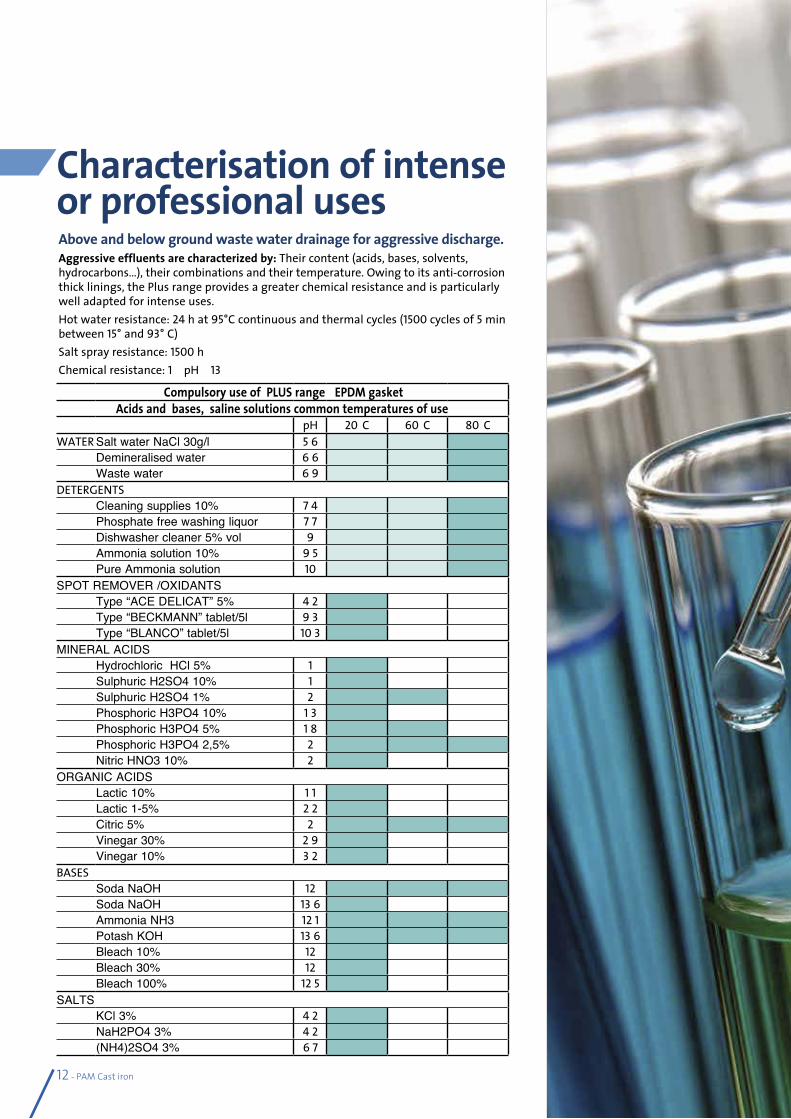
Above and below ground waste water drainage for aggressive discharge.Aggressive effluents are characterized by: Their content (acids, bases, solvents, hydrocarbons…), their combinations and their temperature. Owing to its anti-corrosion thick linings, the Plus range provides a greater chemical resistance and is particularly well adapted for intense uses.Hot water resistance: 24 h at 95°C continuous and thermal cycles (1500 cycles of 5 min between 15° and 93° C)Salt spray resistance: 1500 hChemical resistance: 1 < pH < 13
Characterisation of intense or professional uses
Compulsory use of PLUS range+ EPDM gasketAcids and bases, saline solutions common temperatures of use
pH 20°C 60°C 80°CWATER Salt water NaCl 30g/l 5,6
Demineralised water 6,6Waste water 6,9
DETERGENTSCleaning supplies 10% 7,4Phosphate free washing liquor 7,7Dishwasher cleaner 5% vol 9Ammonia solution 10% 9,5Pure Ammonia solution 10
SPOT REMOVER /OXIDANTSType “ACE DELICAT” 5% 4,2Type “BECKMANN” tablet/5l 9,3Type “BLANCO” tablet/5l 10,3
MINERAL ACIDSHydrochloric HCl 5% 1Sulphuric H2SO4 10% 1Sulphuric H2SO4 1% 2Phosphoric H3PO4 10% 1,3Phosphoric H3PO4 5% 1,8Phosphoric H3PO4 2,5% 2Nitric HNO3 10% 2
ORGANIC ACIDSLactic 10% 1,1Lactic 1-5% 2,2Citric 5% 2Vinegar 30% 2,9Vinegar 10% 3,2
BASESSoda NaOH 12Soda NaOH 13,6Ammonia NH3 12,1Potash KOH 13,6Bleach 10% 12Bleach 30% 12Bleach 100% 12,5
SALTSKCl 3% 4,2NaH2PO4 3% 4,2(NH4)2SO4 3% 6,7
PAM Cast iron - 13
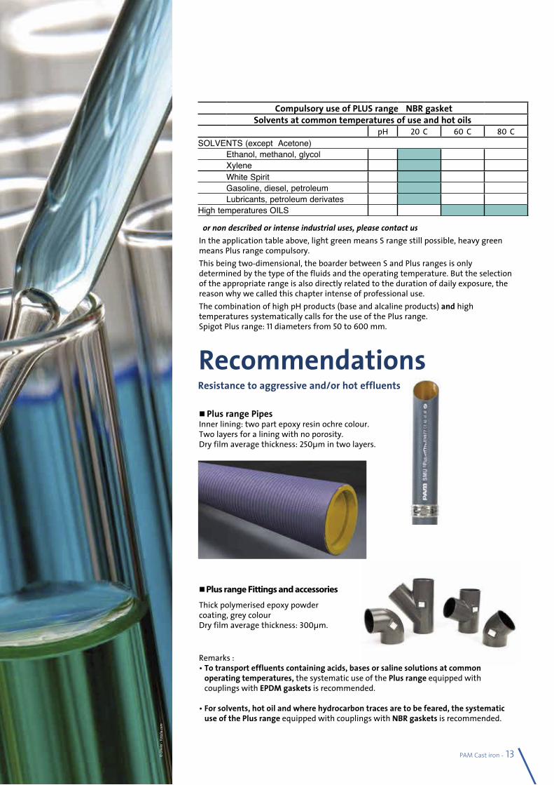
Plus range Pipes Inner lining: two part epoxy resin ochre colour. Two layers for a lining with no porosity.Dry film average thickness: 250µm in two layers.
Thick polymerised epoxy powder coating, grey colourDry film average thickness: 300µm.
Remarks :• To transport effluents containing acids, bases or saline solutions at common
operating temperatures, the systematic use of the Plus range equipped with couplings with EPDM gaskets is recommended.
• For solvents, hot oil and where hydrocarbon traces are to be feared, the systematic use of the Plus range equipped with couplings with NBR gaskets is recommended.
Plus range Fittings and accessories
Compulsory use of PLUS range+ NBR gasketSolvents at common temperatures of use and hot oils
pH 20°C 60°C 80°CSOLVENTS (except Acetone)
Ethanol, methanol, glycol —Xylene —White Spirit —Gasoline, diesel, petroleum —Lubricants, petroleum derivates —
High temperatures OILS
For non described or intense industrial uses, please contact usIn the application table above, light green means S range still possible, heavy green means Plus range compulsory.This being two-dimensional, the boarder between S and Plus ranges is only determined by the type of the fluids and the operating temperature. But the selection of the appropriate range is also directly related to the duration of daily exposure, the reason why we called this chapter intense of professional use.The combination of high pH products (base and alcaline products) and high temperatures systematically calls for the use of the Plus range. Spigot Plus range: 11 diameters from 50 to 600 mm.
RecommendationsResistance to aggressive and/or hot effluents
© O
livie
r - Fo
tolia
.com
14 - PAM Cast iron
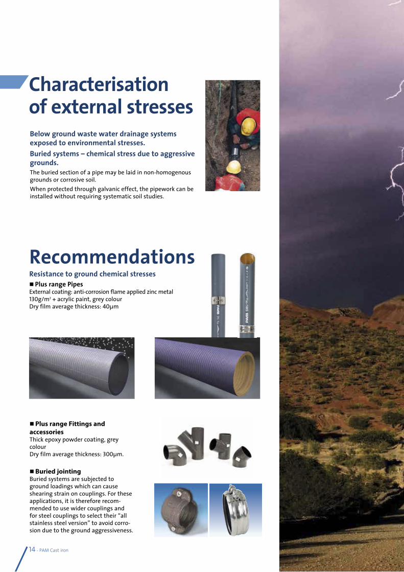
Below ground waste water drainage systems exposed to environmental stresses.Buried systems – chemical stress due to aggressive grounds.The buried section of a pipe may be laid in non-homogenous grounds or corrosive soil. When protected through galvanic effect, the pipework can be installed without requiring systematic soil studies.
Plus range Fittings and accessoriesThick epoxy powder coating, grey colourDry film average thickness: 300µm.
Buried jointingBuried systems are subjected to ground loadings which can cause shearing strain on couplings. For these applications, it is therefore recom-mended to use wider couplings and for steel couplings to select their “all stainless steel version” to avoid corro-sion due to the ground aggressiveness.
Characterisation of external stresses
Recommendations Resistance to ground chemical stresses Plus range PipesExternal coating: anti-corrosion flame applied zinc metal130g/m2 + acrylic paint, grey colourDry film average thickness: 40µm
PAM Cast iron - 15
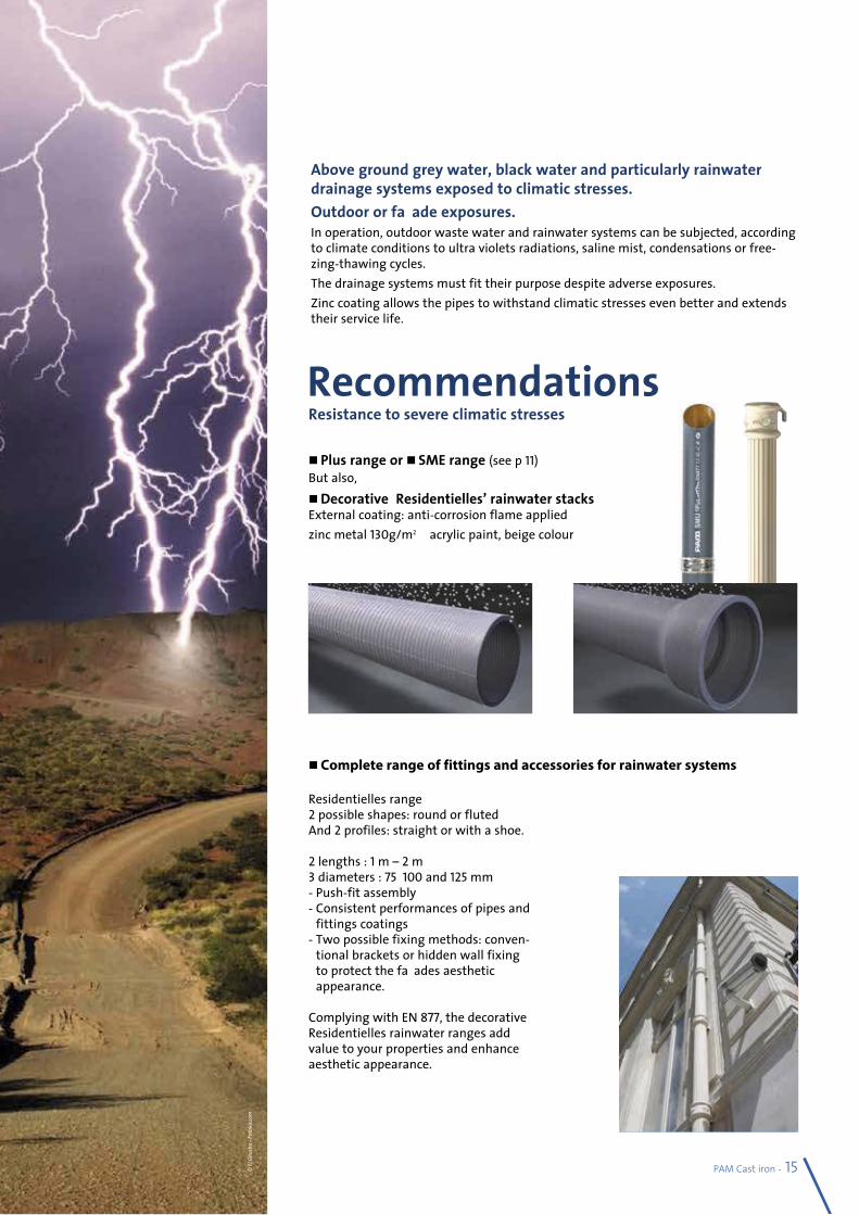
Recommendations Resistance to severe climatic stresses
Above ground grey water, black water and particularly rainwater drainage systems exposed to climatic stresses.Outdoor or façade exposures.In operation, outdoor waste water and rainwater systems can be subjected, according to climate conditions to ultra violets radiations, saline mist, condensations or free-zing-thawing cycles.The drainage systems must fit their purpose despite adverse exposures.Zinc coating allows the pipes to withstand climatic stresses even better and extends their service life.
Plus range or SME range (see p 11) But also, Decorative ‘Residentielles’ rainwater stacks External coating: anti-corrosion flame applied zinc metal 130g/m2+ acrylic paint, beige colour
Residentielles range2 possible shapes: round or flutedAnd 2 profiles: straight or with a shoe. 2 lengths : 1 m – 2 m3 diameters : 75,100 and 125 mm- Push-fit assembly- Consistent performances of pipes and
fittings coatings- Two possible fixing methods: conven-
tional brackets or hidden wall fixing to protect the façades aesthetic appearance.
Complying with EN 877, the decorative Residentielles rainwater ranges add value to your properties and enhance aesthetic appearance.
Complete range of fittings and accessories for rainwater systems
© E
l Gau
cho
- Fot
olia
.com
16 - PAM Cast iron
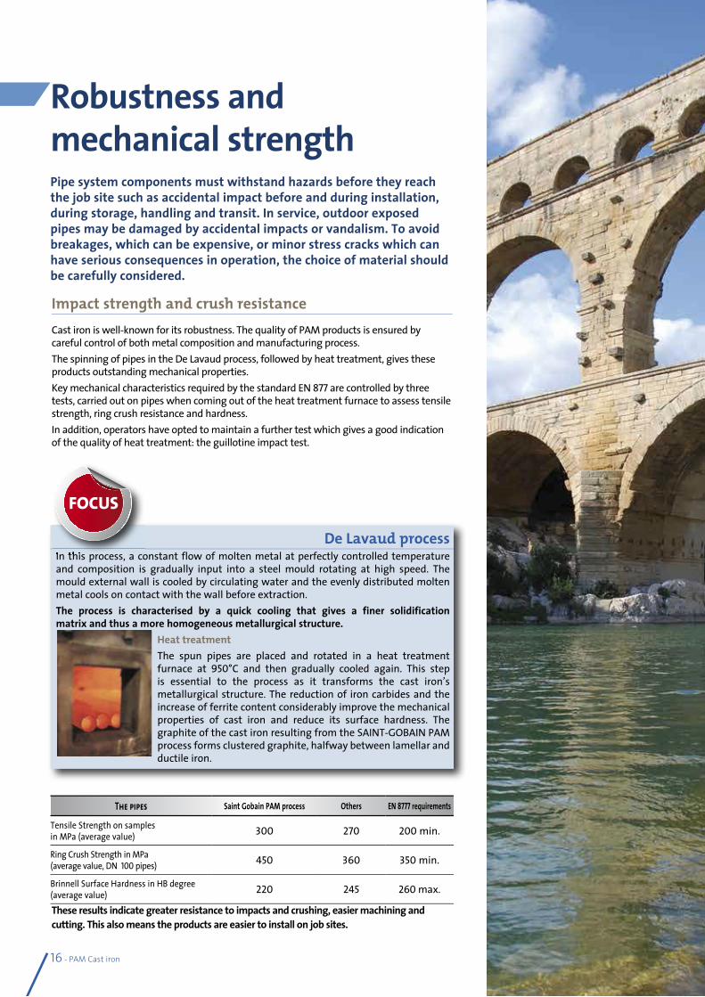
Robustness and mechanical strengthPipe system components must withstand hazards before they reach the job site such as accidental impact before and during installation, during storage, handling and transit. In service, outdoor exposed pipes may be damaged by accidental impacts or vandalism. To avoid breakages, which can be expensive, or minor stress cracks which can have serious consequences in operation, the choice of material should be carefully considered.
Impact strength and crush resistance Cast iron is well-known for its robustness. The quality of PAM products is ensured by careful control of both metal composition and manufacturing process.The spinning of pipes in the De Lavaud process, followed by heat treatment, gives these products outstanding mechanical properties.Key mechanical characteristics required by the standard EN 877 are controlled by three tests, carried out on pipes when coming out of the heat treatment furnace to assess tensile strength, ring crush resistance and hardness.In addition, operators have opted to maintain a further test which gives a good indication of the quality of heat treatment: the guillotine impact test.
The pipes Saint Gobain PAM process Others EN 8777 requirements
Tensile Strength on samples in MPa (average value) 300 270 200 min.
Ring Crush Strength in MPa (average value, DN 100 pipes) 450 360 350 min.
Brinnell Surface Hardness in HB degree (average value) 220 245 260 max.
These results indicate greater resistance to impacts and crushing, easier machining and cutting. This also means the products are easier to install on job sites.
De Lavaud process In this process, a constant flow of molten metal at perfectly controlled temperature and composition is gradually input into a steel mould rotating at high speed. The mould external wall is cooled by circulating water and the evenly distributed molten metal cools on contact with the wall before extraction.The process is characterised by a quick cooling that gives a finer solidification matrix and thus a more homogeneous metallurgical structure.
Heat treatmentThe spun pipes are placed and rotated in a heat treatment furnace at 950°C and then gradually cooled again. This step is essential to the process as it transforms the cast iron’s metallurgical structure. The reduction of iron carbides and the increase of ferrite content considerably improve the mechanical properties of cast iron and reduce its surface hardness. The graphite of the cast iron resulting from the SAINT-GOBAIN PAM process forms clustered graphite, halfway between lamellar and ductile iron.
In this process, a constant flow of molten metal at perfectly controlled temperature
FOCUS
PAM Cast iron - 17
Thermal expansion of plasticsTo allow expansion without damaging the drainage network, plastic pipe systems demand specific accessories – expansion collars or joints, brackets allowing axial movement, in general one out of two.If these precautions were not taken, expansion could be absorbed by the pipework and cause distortion.Cast iron can do without these expensive accessories. It makes the design work easier and decreases the risk of mistakes at installation stage.These properties of cast iron pipe systems are also valuable for engineering structures such as bridges where important expansions have to be carefully addressed to secure the construction project.
Thermal expansion coefficient of cast iron and other materialsThe thermal expansion coefficient for cast iron – 0.01 mm/m/°C – is very low and very similar to that of steel and concrete; the building and the pipe systems will move and will expand together.
For cast iron, the bracketing system is designed to only carry the weight of the pipe and its content, which makes the designers work easier. (See our recommendations in the Specifier’s Manual p 108).Plastic pipes, for themselves, expand considerably with increasing temperature. Their bracketing system must be designed and adapted accordingly, as it can deeply affect the stability of a pipework and its performance over time.
Resistance to thermal expansionMost solids expand when they are heated and are liable to elongate under temperature increase.For pipe systems made of materials that are subjected to high levels of thermal expansion, precautions have to be taken at design stage.Cast iron which expands very little does not require specific bracketing nor expansion collars. It makes the specifers’ design work easier and avoids extra cost at installation stage.
Thermal expansion of cast iron and other materials for 10m and a temperature rise of 50°C.
Thermal expansion coefficient
0,0104 mm/°C.m �5,2 mm
0,07 mm/°C.m �35 mm
0,150 mm/°C.m �75 mm
0,02 mm/°C.m �100 mm
Cast iron
PVC
PP
HDPE
7 times more
14 times more
19 times more
??
18 - PAM Cast iron
Water tightness over timeFailure of water tightness can occur on drainage systems in operation. They are then due to breaks, misalignments, crushes or cracks…Long-lasting water tightness depends on two main factors:• No deterioration of pipes:Cast iron is highly resistant to ovality. Their specified mechanical properties and their stability enable cast iron systems to withstand operating stresses extremely well.• No deterioration of assemblies:Elastomers are carefully selected for the long-term stability of their physico chemical characteristics to ensure the lasting water tightness of the rubber gaskets.
Water tightness of cast iron systemsCast iron is a dense and non-porous material. Cast iron pipe systems are water tight and impervious.Cast iron components, straight and rigid are assembled using metal couplings fitted with elastomer gaskets which ensure that the system is completely water tight.Assemblies benefit from a conventional approach. Made with only simple tools, they allow installation tolerance with no risk of leakage.This ease of installation ensures that the specified performance is always obtained, even in adverse conditions - unlike for plastics when either gluing or welding can be affected by installation hazards (ambient conditions such as temperature or damp) or when personnel with special skills are required.
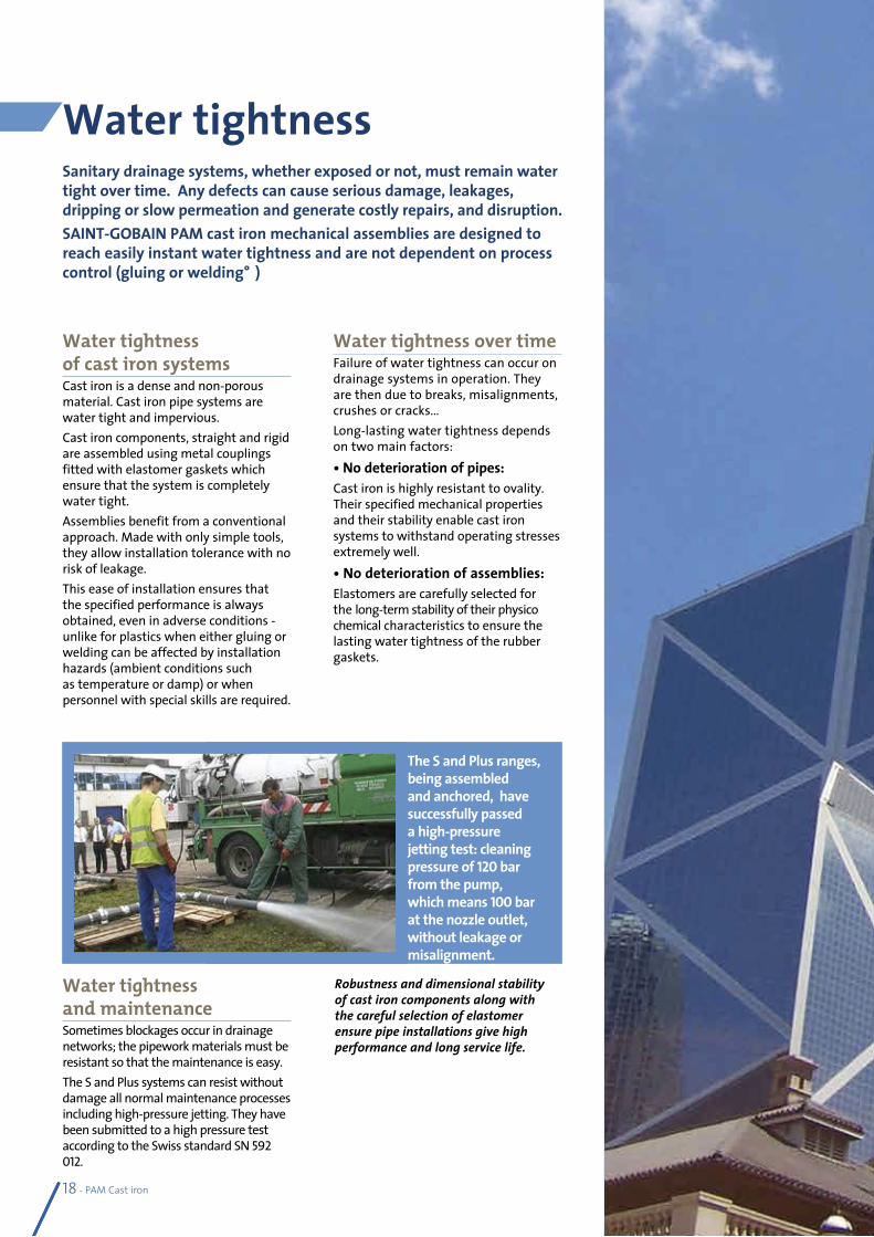
Water tightness and maintenanceSometimes blockages occur in drainage networks; the pipework materials must be resistant so that the maintenance is easy.The S and Plus systems can resist without damage all normal maintenance processes including high-pressure jetting. They have been submitted to a high pressure test according to the Swiss standard SN 592012.
Sanitary drainage systems, whether exposed or not, must remain water tight over time. Any defects can cause serious damage, leakages, dripping or slow permeation and generate costly repairs, and disruption.SAINT-GOBAIN PAM cast iron mechanical assemblies are designed to reach easily instant water tightness and are not dependent on process control (gluing or welding…)
Water tightness
Robustness and dimensional stability of cast iron components along with the careful selection of elastomer ensure pipe installations give high performance and long service life.
The S and Plus ranges, being assembled and anchored, have successfully passed a high-pressure jetting test: cleaning pressure of 120 bar from the pump, which means 100 bar at the nozzle outlet, without leakage or misalignment.
Internal overpressure in drainage networks rarely occurs and is always accidental. Thrust efforts in the overloaded sections have to be addressed to guarantee both water tightness and mechanical stability.As the robust cast iron components can address any pressure hazard, then the couplings will be submitted to the strain.The quality of the couplings and their careful selection according to their field of use will prevent misalignment or disconnection of the pipework.
Internal pressure resistance
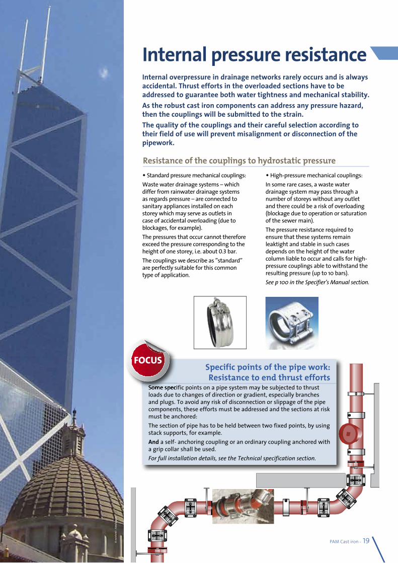
Specific points of the pipe work: Resistance to end thrust efforts
Some specific points on a pipe system may be subjected to thrust loads due to changes of direction or gradient, especially branches and plugs. To avoid any risk of disconnection or slippage of the pipe components, these efforts must be addressed and the sections at risk must be anchored:The section of pipe has to be held between two fixed points, by using stack supports, for example.And a self- anchoring coupling or an ordinary coupling anchored with a grip collar shall be used.For full installation details, see the Technical specification section.
Some specific points on a pipe system may be subjected to thrust
FOCUS
High-pressure mechanical couplings:In some rare cases, a waste water drainage system may pass through a number of storeys without any outlet and there could be a risk of overloading (blockage due to operation or saturation of the sewer main).The pressure resistance required to ensure that these systems remain leaktight and stable in such cases depends on the height of the water column liable to occur and calls for high-pressure couplings able to withstand the resulting pressure (up to 10 bars).See p 100 in the Specifier’s Manual section.
Standard pressure mechanical couplings:Waste water drainage systems – which differ from rainwater drainage systems as regards pressure – are connected to sanitary appliances installed on each storey which may serve as outlets in case of accidental overloading (due to blockages, for example).The pressures that occur cannot therefore exceed the pressure corresponding to the height of one storey, i.e. about 0.3 bar.The couplings we describe as ”standard” are perfectly suitable for this common type of application.
Resistance of the couplings to hydrostatic pressure
PAM Cast iron - 19© m
initc
hii -
Foto
lia.co
m
20 - PAM Cast iron
As components that are integrated in buildings, waste water and rainwater drainage systems must remain in a serviceable condition over the long term in spite of adverse operating conditions.Ageing refers to any gradual, irreversible change in a material’s structure and/or composition, liable to affect its behaviour or serviceability.When a material is selected, the stability of its properties ensures operational reliability over time.
Ageing behaviour
Stability of cast iron mechanical propertiesThe ageing of a material may be due to its own instability, to environment or chemical stresses, to mechanical strains, or a combination of any of those causes.It is an established fact that cast iron offers long service, owing in particular to the stability of its mechanical properties over time.- Cast iron is not sensitive to thermal ageing •Its mechanical strength remains stable. • Its thermal expansion is very low
compared to plastics. • Cast iron pipe systems are not liable
to creep at operating temperatures.
- Cast iron does not deform under mechanical strain
• Its ring stiffness (cold measurement) around 700 kN.m is not affected by temperature and is 87 times that of PVC pipes. It is mainly appreciated for buried pipework.
• Its longitudinal stiffness, which eases bracketing and protects water stream in horizontal sections, remains intact. Its Young modulus of elasticity is ranking from 80 to 120 GPa vs 2 to 5 GPa for PVC.
• Cast iron’s tensile strength is 8 times that of PVC: 200 MPa vs 25. (residual resistance, after 50 years according to the standards). This property is of utmost importance in case of network overloading.
The properties of cast iron ensure the stability of systems and long lasting operational safety.
Resistance to climatic stressesThe properties of materials are extremely important when they are stored or exposed to adverse conditions (extended
exposure to ultraviolet light or wide temperature variations…).Cast iron undergoes no structure modification under climatic stresses.
Ageing of polymers:Deterioration of mechanical properties under temperature stress.Under temperature effect plastics can suffer two kinds of deteriorations, including at operation temperatures:- Creeping is an irreversible elongation
under the combined action of both temperature and an important mechanical strain. Plastic pipe system like PVC or HDPE are particularly sensitive; in horizontal sections, they can bend between two support brackets under their own weight.
- Modification of the elastic limit: most plastic materials will soften under temperature increase. Under temperature decrease on the contrary, they crystallize. PVC for example become rigid and may crack under mechanical strain – their operating temperature range is generally between -20°C to 80°C, but depending on their nature, the range can be much narrower.
Photochemical ageingDepending on their nature, climatic stresses (such as solar radiation, damp or heat) will cause more or less severe photochemical ageing to plastic materials.They can just alter their surface finish, but also deeply modify their mechanical properties and then adversely affect their serviceability.The same can happen through slow chemical attack by solvents or even in aqueous media.
properties under temperature stress.effect plastics can
FOCUS
PAM Cast iron - 21
In particular, it lays down requirements regarding: - Reaction to fire (product range), - Resistance to internal pressure, - Dimensional tolerances, - Tensile strength, crushing strength, - Joints and their leaktightness, - Inner lining and external coatings and
their suitability.It also defines test methods and the quality management system. EN 877 is a self-declared standard; the manufacturer is allowed to self declare that his product complies with this standard.Only compliance with EN 877 that is validated by a third party for all criteria and periodically tested can guarantee the performance of the systems you specify.The quality of the SMU / ENSIGN S, SMU / ENSIGN Plus, SME and EEZI-FIT product ranges are guaranteed by the following marks of approval: BBA, Kitemark and/or Marque NF.
Quality Management SystemThe plants which manufacture our products are certified for their compliance with the ISO 9001 standard which specifies requirements for a quality management system. The scope of this standard covers product design and development and the quality control of procurements, training, and administrative follow-up.
Products performancesPAM pipe systems comply with European standard EN 877, applicable to a system (cast iron pipes and fittings, couplings and accessories for building drainage). This standard, specifying the technical requirements for cast iron products, is the most demanding in the market.
Compliance with standards and quality marks
European standards
International standards
Cast iron pipes and fittings, their joints and accessories for the evacuation of water from buildings. Requirements, test methods and quality assurance
EN 877/A1
Cast iron drainage pipes and fittings (spigot) ISO 6594
Elastomeric seals - Material requirements EN 681-1 ISO 4633
Requirements for a quality management system design, product development, production, installation and after sales support
ISO 9001
Environmental management systemRequirements with guidance for use
ISO 14001
Testing standards
Fire testsFire classification of construction products and building elements.Classification using data from reaction to fire tests
EN 13501
Reaction to fire tests for building products - Part 1 Building products excluding floorings exposed to the thermal attack by a single burning item
EN 13823
Measurement of noiseLaboratory measurement of noise from waste water installations
EN 14366
??
22 - PAM Cast iron
For fire safety in a building, the major responsibility rests with the project manager who must respect the Regulation in force. In buildings at risk like multi storey buildings, materials with reduced flammability should be selected to apply precautionary principle. The following two concepts are applied as regards fire safety: Reaction to fire and fire resistance.
Fire safetyProtect people and property
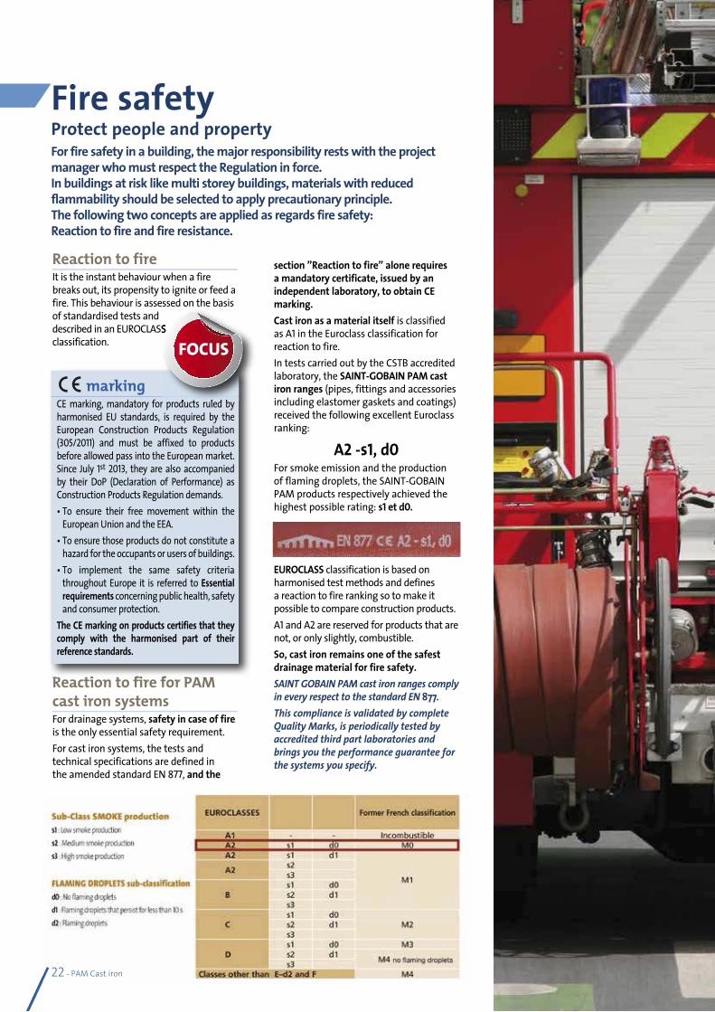
Reaction to fire It is the instant behaviour when a fire breaks out, its propensity to ignite or feed a fire. This behaviour is assessed on the basis of standardised tests and described in an EUROCLASS classification.
Reaction to fire for PAM cast iron systemsFor drainage systems, safety in case of fire is the only essential safety requirement.For cast iron systems, the tests and technical specifications are defined in the amended standard EN 877, and the
section ”Reaction to fire” alone requires a mandatory certificate, issued by an independent laboratory, to obtain CE marking.Cast iron as a material itself is classified as A1 in the Euroclass classification for reaction to fire.In tests carried out by the CSTB accredited laboratory, the SAINT-GOBAIN PAM cast iron ranges (pipes, fittings and accessories including elastomer gaskets and coatings) received the following excellent Euroclass ranking:
A2 -s1, d0For smoke emission and the production of flaming droplets, the SAINT-GOBAIN PAM products respectively achieved the highest possible rating: s1 et d0.
EUROCLASS classification is based on harmonised test methods and defines a reaction to fire ranking so to make it possible to compare construction products.A1 and A2are reserved for products that are not, or only slightly, combustible.So, cast iron remains one of the safest drainage material for fire safety.SAINT GOBAIN PAM cast iron ranges comply in every respect to the standard EN 877. This compliance is validated by complete Quality Marks, is periodically tested by accredited third part laboratories and brings you the performance guarantee for the systems you specify.
Reaction to fire for PAM
marking CE marking, mandatory for products ruled by harmonised EU standards, is required by the European Construction Products Regulation (305/2011) and must be affixed to products before allowed pass into the European market. Since July 1st 2013, they are also accompanied by their DoP (Declaration of Performance) as Construction Products Regulation demands.• To ensure their free movement within the
European Union and the EEA.• To ensure those products do not constitute a
hazard for the occupants or users of buildings.• To implement the same safety criteria
throughout Europe it is referred to Essential requirements concerning public health, safety and consumer protection.
The CE marking on products certifies that they comply with the harmonised part of their reference standards.
described in an EUROCLASS
CE marking, mandatory for products ruled by
FOCUS
22 - PAM Cast iron
PAM Cast iron - 23
Many buildings are not protected enough against fire hazards. It means that fire can spread rapidly, can destroy the building and the properties in a few hours and jeopardize the occupants’ lives.When a fire breaks out, the first objective is to slow down its spreading both horizontally and vertically.Drainage systems must be selected so that they resist the passage of fire and do not feed it.
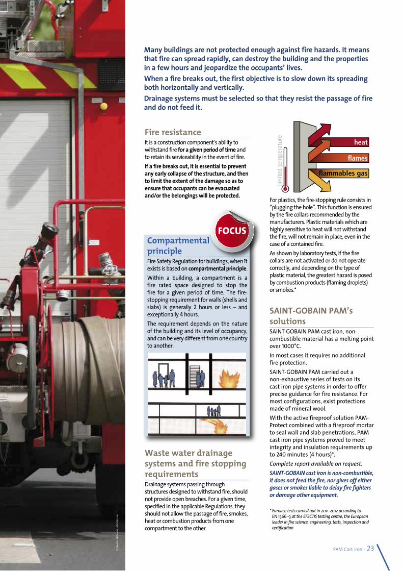
Fire resistance It is a construction component’s ability to withstand fire for a given period of time and to retain its serviceability in the event of fire.If a fire breaks out, it is essential to prevent any early collapse of the structure, and then to limit the extent of the damage so as to ensure that occupants can be evacuated and/or the belongings will be protected.
Waste water drainage systems and fire stopping requirementsDrainage systems passing through structures designed to withstand fire, should not provide open breaches. For a given time, specified in the applicable Regulations, they should not allow the passage of fire, smokes, heat or combustion products from one compartment to the other.
For plastics, the fire-stopping rule consists in ”plugging the hole”. This function is ensured by the fire collars recommended by the manufacturers. Plastic materials which are highly sensitive to heat will not withstand the fire, will not remain in place, even in the case of a contained fire.As shown by laboratory tests, if the fire collars are not activated or do not operate correctly, and depending on the type of plastic material, the greatest hazard is posed by combustion products (flaming droplets) or smokes.*
SAINT-GOBAIN PAM’s solutionsSAINT GOBAIN PAM cast iron, non-combustible material has a melting point over 1000°C.In most cases it requires no additional fire protection.SAINT-GOBAIN PAM carried out a non-exhaustive series of tests on its cast iron pipe systems in order to offer precise guidance for fire resistance. For most configurations, exist protections made of mineral wool. With the active fireproof solution PAM-Protect combined with a fireproof mortar to seal wall and slab penetrations, PAM cast iron pipe systems proved to meet integrity and insulation requirements up to 240 minutes (4 hours)*.Complete report available on request.SAINT-GOBAIN cast iron is non-combustible, it does not feed the fire, nor gives off either gases or smokes liable to delay fire fighters or damage other equipment.
* Furnace tests carried out in 2011-2012 according to EN 1366 -3 at the EFECTIS testing centre, the European leader in fire science, engineering, tests, inspection and certification
Compartmental principle Fire Safety Regulation for buildings, when it exists is based on compartmental principle.Within a building, a compartment is a fire rated space designed to stop the fire for a given period of time. The fire-stopping requirement for walls (shells and slabs) is generally 2 hours or less – and exceptionally 4 hours.The requirement depends on the nature of the building and its level of occupancy, and can be very different from one country to another.
Compartmental
Fire Safety Regulation for buildings, when it
FOCUS
© G
autie
r Will
aum
e - Fo
tolia
.com
limite
d te
mpe
ratu
re
heat
�ames
�ammables gas
24 - PAM Cast iron
Noise in buildings is considered to be detrimental to health and the quality of life. Efforts have been made, in the last 30 years, to attenuate the sounds coming from the street, worsening the perception of the sounds emitted within the buildings. Heat insulation policies aiming at reducing energy consumption will also heighten these perceptions. Among the priority criteria in the comparative performances of drainage materials, acoustic performance is reckoned to be second only to fire safety: cast iron pipe systems have intrinsic acoustic properties. Owing to the development in accessories equipment, they offer outstanding performances.
Acoustics
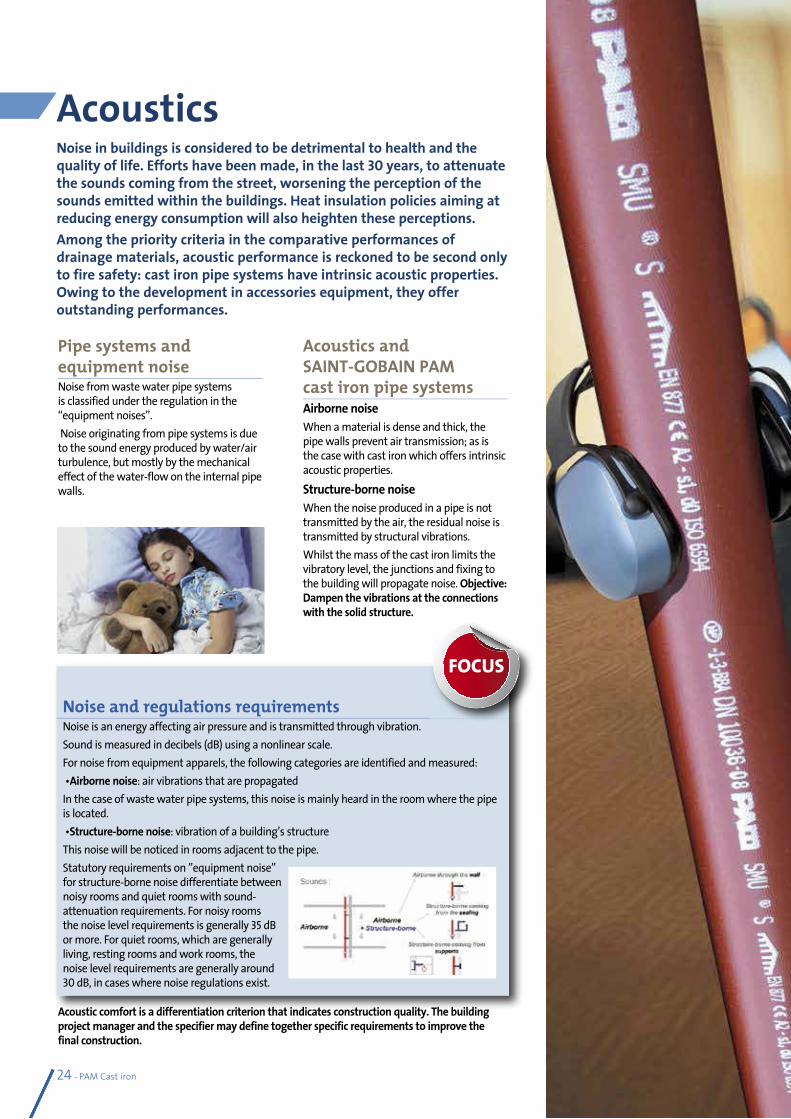
Pipe systems and equipment noiseNoise from waste water pipe systems is classified under the regulation in the “equipment noises”. Noise originating from pipe systems is due to the sound energy produced by water/air turbulence, but mostly by the mechanical effect of the water-flow on the internal pipe walls.
Acoustics and SAINT-GOBAIN PAM cast iron pipe systemsAirborne noiseWhen a material is dense and thick, the pipe walls prevent air transmission; as is the case with cast iron which offers intrinsic acoustic properties.Structure-borne noiseWhen the noise produced in a pipe is not transmitted by the air, the residual noise is transmitted by structural vibrations.Whilst the mass of the cast iron limits the vibratory level, the junctions and fixing to the building will propagate noise. Objective: Dampen the vibrations at the connections with the solid structure.
Noise and regulations requirementsNoise is an energy affecting air pressure and is transmitted through vibration.Sound is measured in decibels (dB) using a nonlinear scale.For noise from equipment apparels, the following categories are identified and measured: •Airborne noise: air vibrations that are propagatedIn the case of waste water pipe systems, this noise is mainly heard in the room where the pipe is located. •Structure-borne noise: vibration of a building’s structureThis noise will be noticed in rooms adjacent to the pipe.Statutory requirements on ”equipment noise” for structure-borne noise differentiate between noisy rooms and quiet rooms with sound-attenuation requirements. For noisy rooms the noise level requirements is generally 35 dB or more. For quiet rooms, which are generally living, resting rooms and work rooms, the noise level requirements are generally around 30 dB, in cases where noise regulations exist.
FOCUS
Acoustic comfort is a differentiation criterion that indicates construction quality. The building project manager and the specifier may define together specific requirements to improve the final construction.
PAM Cast iron - 25
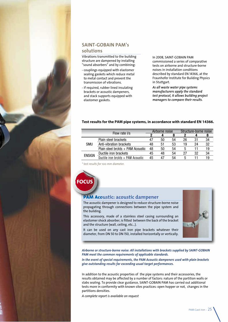
SAINT-GOBAIN PAM’s solutionsVibrations transmitted to the building structure are dampened by installing “sound absorbers” and by combining:- couplings equipped with elastomer
sealing gaskets which reduce metal to metal contact and prevent the transmission of vibrations.
- if required, rubber lined insulating brackets or acoustic dampeners, and stack supports equipped with elastomer gaskets.
In 2008, SAINT-GOBAIN PAM commissioned a series of comparative tests on airborne and structure-borne noises in installation conditions described by standard EN 14366, at the Fraunhofer Institute for Building Physics in Stuttgart.As all waste water pipe systems manufacturers apply the standard test protocol, it allows building project managers to compare their results.
Airborne or structure-borne noise: All installations with brackets supplied by SAINT-GOBAIN PAM meet the common requirements of applicable standards.In the event of special requirements, the PAM Acoustic dampeners used with plain brackets give outstanding results far exceeding usual target performances.
In addition to the acoustic properties of the pipe systems and their accessories, the results obtained may be affected by a number of factors: nature of the partition walls or slabs sealing. To provide clear guidance, SAINT-GOBAIN PAM has carried out additional tests more in conformity with known sites practices: open hopper or not, changes in the partitions densities.A complete report is available on request
PAM Acoustic: acoustic dampenerThe acoustic dampener is designed to reduce structure-borne noise propagating through connections between the pipe system and the building.This accessory, made of a stainless steel casing surrounding an elastomer shock absorber, is fitted between the back of the bracket and the structure (wall, ceiling, etc...).It can be used on any cast iron pipe brackets whatever their diameter, from DN 50 to DN 150, installed horizontally or vertically.
Flow rate l/s Airborne noise Structure-borne noise2 4 8 2 4 8
SMUPlain steel brackets 47 50 54 26 31 34Anti-vibration brackets 48 51 53 19 24 32Plain steel brckts + PAM Acoustic 48 50 54 5 11 19
ENSIGNDuctile iron brackets 45 48 54 27 32 34Ductile iron brckts + PAM Acoustic 45 47 54 5 11 19
PAM Acoustic: acoustic dampener
FOCUS
Test results for the PAM pipe systems, in accordance with standard EN 14366.
* test results for 100 mm diameter.
26 - PAM Cast iron
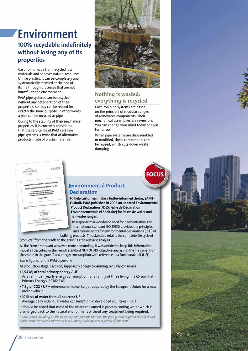
Environment100% recyclable indefinitely without losing any of its propertiesCast iron is made from recycled raw materials and so saves natural resources. Unlike plastics, it can be completely and systematically recycled at the end of its life through processes that are not harmful to the environment.PAM pipe systems can be recycled without any deterioration of their properties, so they can be reused for exactly the same purpose. In other words, a pipe can be recycled as pipe.Owing to the stability of their mechanical properties, it is currently considered that the service life of PAM cast iron pipe systems is twice that of alternative products made of plastic materials.
Nothing is wasted: everything is recycledCast iron pipe systems are based on the principle of modular ranges of removable components. Their mechanical assemblies are reversible. You can change your mind today or even tomorrow.When pipe systems are disassembled or modified, these components can be reused, which cuts down waste dumping.
Environmental Product Declaration To help customers make a better-informed choice, SAINT-GOBAIN PAM published in 2006 an updated Environmental Product Declaration (FDES: Fiche de Déclaration Environnementale et Sanitaire) for its waste water and rainwater ranges.In response to a worldwide need for harmonisation, the international standard ISO 21930 provides the principles and requirements for environmental declarations (EPD) of
building products. This standard retains the complete life cycle of products ”from the cradle to the grave” as the relevant analysis. As the French standard was even more demanding, it was decided to keep this information model as described in the French standard NF P 01 010: objective analysis of the life cycle ”from the cradle to the grave” and energy consumption with reference to a functional unit (UF)*.Some figures for the PAM pipework:At production stage, cast iron, supposedly energy consuming, actually consumes:• 1,94 Mj of total primary energy / UF
As a reminder: yearly energy consumption for a family of three living in a 65 sqm flat = Primary Energy= 62382.5 Mj
• 118g of CO2 / UF = reference emission target adopted by the European Union for a new motor vehicle.
• 10 litres of water from all sources/ UF Average daily individual water consumption in developed countries= 150 l
It should be noted that most of the water consumed is process cooling water which is discharged back to the natural environment without any treatment being required.* 1 ml = ratio including all the necessary components to make the pipe system required to collect and drain waste water and rainwater in a 4-storey building over a period of one year”.
Environmental Product Declaration To help customers make a better-informed choice, SAINT-GOBAIN PAM published in Product Declaration (FDES: Fiche de Déclaration Environnementale et Sanitaire) for its waste water and rainwater ranges.In response to a worldwide need for harmonisation, the international standard ISO
building products. This standard retains the complete life cycle of
FOCUS
PAM Cast iron - 27
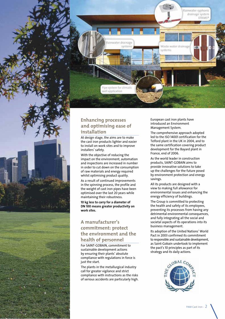
Enhancing processes and optimising ease of installationAt design stage, the aims are to make the cast iron products lighter and easier to install on work sites and to improve installers’ safety.With the objective of reducing the impact on the environment, automation and inspections are increased in number in order to cut down on the consumption of raw materials and energy required whilst optimising product quality.As a result of continued improvements in the spinning process, the profile and the weight of cast iron pipes have been optimised over the last 20 years while maintaining their robustness.10 kg less to carry for a diameter of DN 100 means greater productivity on work sites.
A manufacturer’s commitment: protect the environment and the health of personnelFor SAINT-GOBAIN, commitment to sustainable development actions by ensuring their plants’ absolute compliance with regulations in force is just the start.The plants in the metallurgical industry call for greater vigilance and strict compliance with instructions as the risks of serious accidents are particularly high.
European cast iron plants have introduced an Environment Management System. The comprehensive approach adopted led to the ISO 14001 certification for the Telford plant in the UK in2004, and to the same certification covering product development for the Bayard plant in France, end of 2006.As the world leader in construction products, SAINT-GOBAIN aims to provide innovative solutions to take up the challenges for the future posed by environment protection and energy savings.All its products are designed with a view to making full allowance for environmental issues and enhancing the energy efficiency of buildings.The Group is committed to protecting the health and safety of its employees, preventing its processes from having any detrimental environmental consequences, and fully integrating all the social and societal aspects of its operations into its business management.Its adoption of the United Nations’ World Pact in 2003 confirmed its commitment to responsible and sustainable development, as Saint-Gobain undertook to implement the pact’s 10 principles as part of its strategy and its daily actions.
28 - PAM Cast iron
stimulateyour networksA modern technique based on a dynamic principle
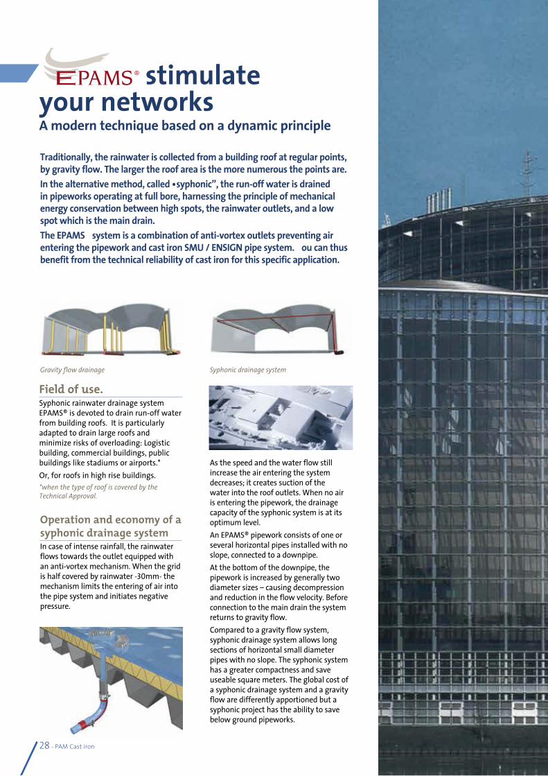
Operation and economy of a syphonic drainage systemIn case of intense rainfall, the rainwater flows towards the outlet equipped with an anti-vortex mechanism. When the grid is half covered by rainwater -30mm- the mechanism limits the entering of air into the pipe system and initiates negative pressure.
Field of use.Syphonic rainwater drainage system EPAMS® is devoted to drain run-off water from building roofs. It is particularly adapted to drain large roofs and minimize risks of overloading: Logistic building, commercial buildings, public buildings like stadiums or airports.* Or, for roofs in high rise buildings.*when the type of roof is covered by the Technical Approval.
Traditionally, the rainwater is collected from a building roof at regular points, by gravity flow. The larger the roof area is the more numerous the points are.In the alternative method, called “syphonic”, the run-off water is drained in pipeworks operating at full bore, harnessing the principle of mechanical energy conservation between high spots, the rainwater outlets, and a low spot which is the main drain. The EPAMS® system is a combination of anti-vortex outlets preventing air entering the pipework and cast iron SMU / ENSIGN pipe system. You can thus benefit from the technical reliability of cast iron for this specific application.
Gravity flow drainage Syphonic drainage system
As the speed and the water flow still increase the air entering the system decreases; it creates suction of the water into the roof outlets. When no air is entering the pipework, the drainage capacity of the syphonic system is at its optimum level. An EPAMS® pipework consists of one or several horizontal pipes installed with no slope, connected to a downpipe.At the bottom of the downpipe, the pipework is increased by generally two diameter sizes – causing decompression and reduction in the flow velocity. Before connection to the main drain the system returns to gravity flow.Compared to a gravity flow system, syphonic drainage system allows long sections of horizontal small diameter pipes with no slope. The syphonic system has a greater compactness and save useable square meters. The global cost of a syphonic drainage system and a gravity flow are differently apportioned but a syphonic project has the ability to save below ground pipeworks.
PAM Cast iron - 29
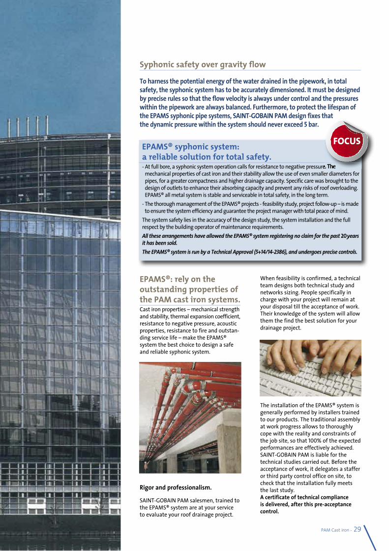
Syphonic safety over gravity flow
EPAMS® syphonic system: a reliable solution for total safety.- At full bore, a syphonic system operation calls for resistance to negative pressure. The
mechanical properties of cast iron and their stability allow the use of even smaller diameters for pipes, for a greater compactness and higher drainage capacity. Specific care was brought to the design of outlets to enhance their absorbing capacity and prevent any risks of roof overloading. EPAMS® all metal system is stable and serviceable in total safety, in the long term.
- The thorough management of the EPAMS® projects - feasibility study, project follow-up – is made to ensure the system efficiency and guarantee the project manager with total peace of mind.
The system safety lies in the accuracy of the design study, the system installation and the full respect by the building operator of maintenance requirements.All these arrangements have allowed the EPAMS® system registering no claim for the past 20 years it has been sold.The EPAMS® system is run by a Technical Approval (5+14/14-2386), and undergoes precise controls.
At full bore, a syphonic system operation calls for resistance to negative pressure. The
FOCUS
To harness the potential energy of the water drained in the pipework, in total safety, the syphonic system has to be accurately dimensioned. It must be designed by precise rules so that the flow velocity is always under control and the pressures within the pipework are always balanced. Furthermore, to protect the lifespan of the EPAMS syphonic pipe systems, SAINT-GOBAIN PAM design fixes that the dynamic pressure within the system should never exceed 5 bar.
EPAMS®: rely on the outstanding properties of the PAM cast iron systems.Cast iron properties – mechanical strength and stability, thermal expansion coefficient, resistance to negative pressure, acoustic properties, resistance to fire and outstan-ding service life – make the EPAMS® system the best choice to design a safe and reliable syphonic system.
Rigor and professionalism.
SAINT-GOBAIN PAM salesmen, trained to the EPAMS® system are at your service to evaluate your roof drainage project.
When feasibility is confirmed, a technical team designs both technical study and networks sizing. People specifically in charge with your project will remain at your disposal till the acceptance of work. Their knowledge of the system will allow them the find the best solution for your drainage project.
The installation of the EPAMS® system is generally performed by installers trained to our products. The traditional assembly at work progress allows to thoroughly cope with the reality and constraints of the job site, so that 100% of the expected performances are effectively achieved.SAINT-GOBAIN PAM is liable for the technical studies carried out. Before the acceptance of work, it delegates a staffer or third party control office on site, to check that the installation fully meets the last study.A certificate of technical compliance is delivered, after this pre-acceptance control.
30 - PAM Cast iron
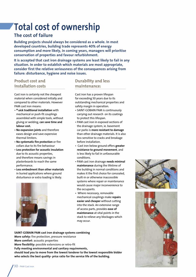
Total cost of ownershipThe cost of failureBuilding projects should always be consider ed as a whole. In most developed countries, building trade represents 40% of energy consumption and more likely, in coming years, managers will prioritise conservation of properties and favour refurbishment.It is accepted that cast iron drainage systems are least likely to fail in any situation. In order to establish which materials are most appropriate, consider first the relative seriousness of the consequences arising from failure: disturbance, hygiene and noise issues.
Product cost and installation costs
Cast iron is certainly not the cheapest material when considered initially and compared to other materials. However PAM cast iron means:• Quick traditional installation with
mechanical or push-fit couplings assembled with simple tools, without gluing or welding, can save time and labour cost.
• No expansion joints and therefore eases design and save expensive thermal limiters.
• No systematic fire protection or fire collars due to its fire behaviour
• Less protection for acoustic insulation due to its acoustic properties, and therefore means savings in plasterboards to reach the same performance.
• Less embedment than other materials in buried applications where ground disturbance or extra loading is likely.
Durability and less maintenance:
Cast iron has a proven lifespan far exceeding 50 years due to its outstanding mechanical properties and safety margin in operation.• SAINT-GOBAIN PAM is continuously
carrying out research on its coatings to protect this lifespan.
• PAM cast iron in exposed sections of the drainage system, ie. basement car parks is more resistant to damage than other drainage materials. It is also less sensitive to cracks and breakage before installation.
• Cast iron below ground offers greater resistance to ground movement, and is less likely to fail in unfavourable conditions.
• PAM cast iron drainage needs minimal maintenance during the lifetime of the building in normal conditions and makes it the first choice for concealed, built-in or otherwise inaccessible systems where repair or maintenance would cause major inconvenience to the occupants.
• Where necessary, removable mechanical couplings make repairs easier and cheaper without cutting into the stack. An extensive range of access parts, provides ease of maintenance at vital points in the stack to relieve any blockages which may occur.
SAINT-GOBAIN PAM cast iron drainage systems combining More safety: fire protection, pressure resistanceMore comfort: acoustic propertiesMore flexibility: possible extensions or retro-fitFully meeting environmental and sanitary requirements,should lead you to move from the lowest tenderer to the lowest responsible bidder who selects the best quality- price ratio for the service life of the building.
PAM Cast iron - 31
Products catalogue
Sect
ion 2
PRODUCT CALATOGUE
SAINT-GOBAIN cast iron pipe systems SMU – ENSIGN S, SMU – ENSIGN Plus, SME socket system and EEZI-FIT socket fittings.
l Comprehensive spigot or socket ranges of pipes fittings and accessories
l Consistent performances for above ground and below ground drainage applications
l Ease of installation with mechanical assembly allowing adjustments onsite
l Easy versatile assembly - retro-fitting of additions or changes to soil stacks
32 - PAM Cast iron
PAM SMU / ENSIGN®S
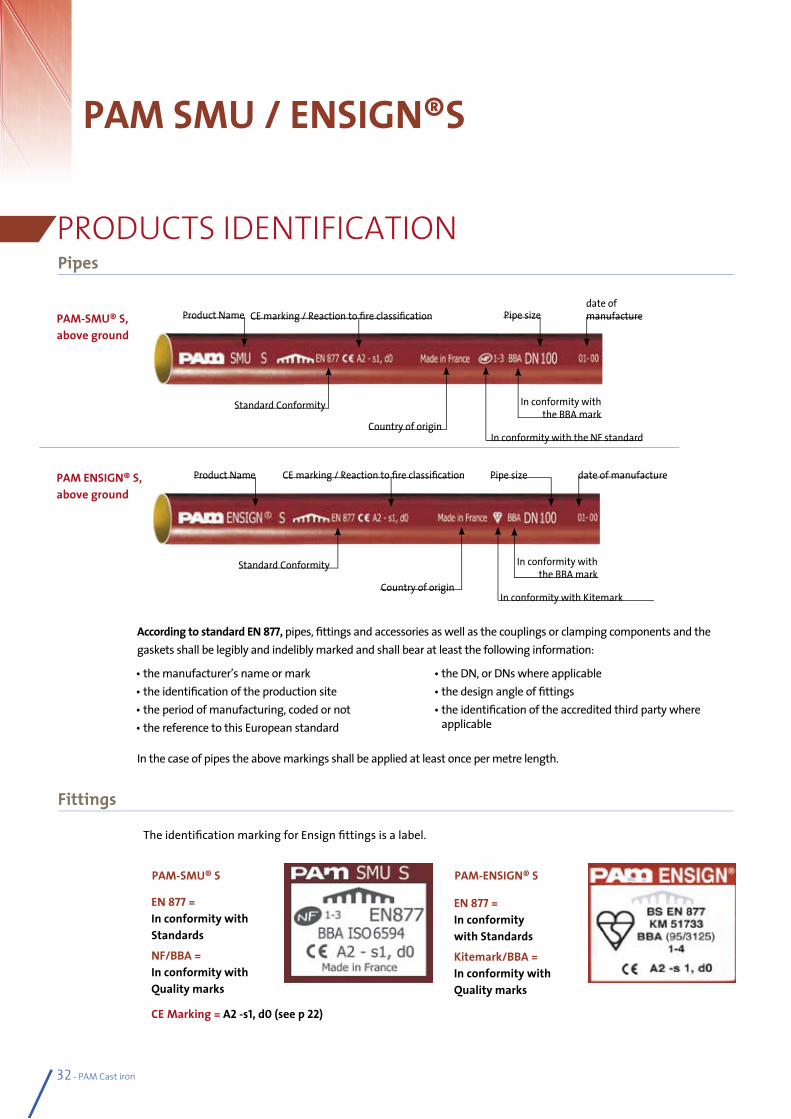
According to standard EN 877, pipes, fittings and accessories as well as the couplings or clamping components and thegaskets shall be legibly and indelibly marked and shall bear at least the following information:
In the case of pipes the above markings shall be applied at least once per metre length.
PAM-SMU® S, above ground
PAM ENSIGN® S, above ground
Country of originIn conformity with Kitemark
In conformity with the BBA mark
Standard Conformity
Product Name Pipe sizeCE marking / Reaction to fire classification date of manufacture
PAM-SMU® S
EN 877 = In conformity with Standards
NF/BBA = In conformity with Quality marks
PAM-ENSIGN® S
EN 877 = In conformity with Standards
Kitemark/BBA = In conformity with Quality marks
Pipes
Fittings
PRODUCTS IDENTIFICATION
The identification marking for Ensign fittings is a label.
• the manufacturer’s name or mark• the identification of the production site• the period of manufacturing, coded or not • the reference to this European standard
• the DN, or DNs where applicable• the design angle of fittings• the identification of the accredited third party where
applicable
Country of originIn conformity with the NF standard
In conformity with the BBA mark
Standard Conformity
Product Namedate of manufacturePipe sizeCE marking / Reaction to fire classification
CE Marking = A2 -s1, d0 (see p 22)
PAM Cast iron - 33
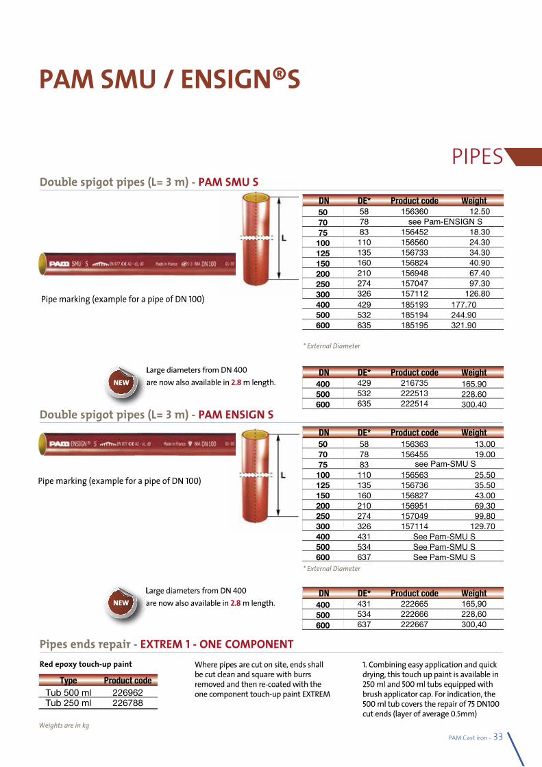
Double spigot pipes (L= 3 m) - PAM ENSIGN S
Red epoxy touch-up paint
PAM SMU / ENSIGN®S
PIPES
Weights are in kg
Where pipes are cut on site, ends shall be cut clean and square with burrs removed and then re-coated with the one component touch-up paint EXTREM
1. Combining easy application and quick drying, this touch up paint is available in 250 ml and 500 ml tubs equipped with brush applicator cap. For indication, the 500 ml tub covers the repair of 75 DN100 cut ends (layer of average 0.5mm)
Double spigot pipes (L= 3 m) - PAM SMU S
Pipe marking (example for a pipe of DN 100)
Pipe marking (example for a pipe of DN 100)
* External Diameter
* External Diameter
DN DE* Product code Weight50 58 156360 12.5070 78 see Pam-ENSIGN S75 83 156452 18.30
100 110 156560 24.30125 135 156733 34.30150 160 156824 40.90200 210 156948 67.40250 274 157047 97.30300 326 157112 126.80400 429 185193 177.70500 532 185194 244.90600 635 185195 321.90
DN DE* Product code Weight50 58 156363 13.0070 78 156455 19.0075 83 see Pam-SMU S100 110 156563 25.50125 135 156736 35.50150 160 156827 43.00200 210 156951 69.30250 274 157049 99.80300 326 157114 129.70400 431 See Pam-SMU S500 534 See Pam-SMU S600 637 See Pam-SMU S
DN DE* Product code Weight400 431 222665 165,90500 534 222666 228,60600 637 222667 300,40
Type Product codeTub 500 ml 226962Tub 250 ml 226788
Pipes ends repair - EXTREM 1 - ONE COMPONENT
Large diameters from DN 400 are now also available in 2.8 m length.
DN DE* Product code Weight400 429 216735 165.90500 532 222513 228.60600 635 222514 300.40
Large diameters from DN 400 are now also available in 2.8 m length.Large diameters from DN are now also available in NEW
Large diameters from DN are now also available in NEW
All dimensions are in mm and nominal weights in kg34 - PAM Cast iron
PAM SMU / ENSIGN®S
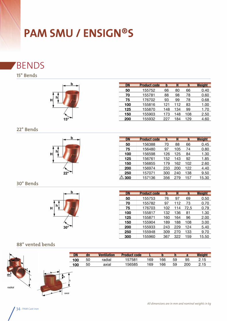
BENDS15° Bends
22° Bends
30° Bends
DN Product code b H h Weight50 155752 66 80 66 0.4070 155781 88 98 78 0.6075 176702 93 99 78 0.68100 155816 121 112 83 1.00125 155870 148 134 99 1.70150 155903 173 148 108 2.50200 155932 227 184 129 4.60
DN Product code b H h Weight50 156388 70 88 66 0.4575 156480 97 105 74 0.80100 156598 126 125 84 1.30125 156761 152 143 92 1.85150 156855 179 162 102 2.60200 156974 233 200 122 4.40250 157071 300 240 138 9.50300 157136 356 279 157 15.30
DN Product code b H h Weight50 155753 76 97 69 0.5070 155782 97 112 73 0.7075 176703 102 114 72,5 0.79100 155817 132 136 81 1.30125 155871 160 164 96 2.00150 155904 189 188 108 3.00200 155933 243 229 124 5.40250 155948 309 270 133 9.70300 155960 367 322 159 15.50
axial
b
a
h
L
88° vented bends
DN dn Ventilation Product code L b h a Weight100 50 radial 157581 169 166 59 95 2.15100 50 axial 156585 169 166 59 200 2.15
h
L
ba
radial
PAM Cast iron - 35
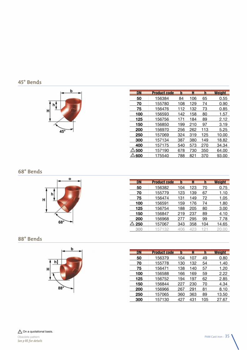
45° Bends
68° Bends
88° Bends
DN Product code b H h Weight50 156384 84 106 65 0.5570 155780 108 129 74 0.9075 156476 112 132 73 0.85100 156593 142 158 80 1.57125 156756 171 184 89 2.12150 156850 199 210 97 3.19200 156970 256 262 113 5.25250 157069 324 319 125 10.00300 157134 387 380 149 18.82400 157175 540 573 270 34.34500 157190 678 730 350 64.00600 175540 788 821 370 93.00
DN Product code b H h Weight50 156379 104 107 49 0.8070 155778 130 132 54 1.4075 156471 138 140 57 1.20100 156588 166 169 59 2.22125 156752 194 197 62 2.85150 156844 227 230 70 4.34200 156966 267 291 81 8.10250 157065 360 363 89 13.50300 157130 427 431 105 27.67
DN Product code b H h Weight50 156382 104 123 70 0.7570 155779 123 139 67 1.1075 156474 131 149 72 1.05100 156591 159 176 74 1.80125 156754 188 205 80 3.00150 156847 219 237 89 4.10200 156968 277 295 99 7.78250 157067 343 358 104 14.65300 157132 406 423 121 20.00
On a quotational basis.
Obsolete pa tternSee p 85 for details
36 - PAM Cast iron
PAM SMU / ENSIGN®S
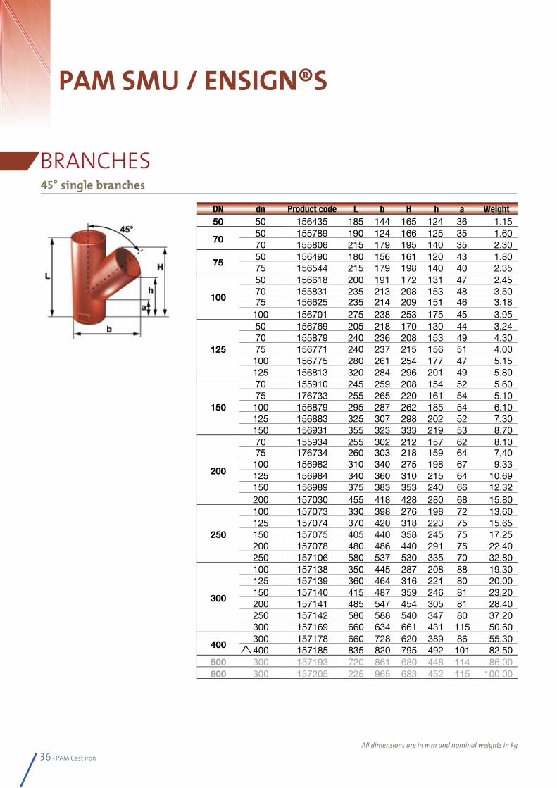
BRANCHES45° single branches
DN dn Product code L b H h a Weight50 50 156435 185 144 165 124 36 1.15
7050 155789 190 124 166 125 35 1.6070 155806 215 179 195 140 35 2.30
7550 156490 180 156 161 120 43 1.8075 156544 215 179 198 140 40 2.35
100
50 156618 200 191 172 131 47 2.4570 155831 235 213 208 153 48 3.5075 156625 235 214 209 151 46 3.18100 156701 275 238 253 175 45 3.95
125
50 156769 205 218 170 130 44 3.2470 155879 240 236 208 153 49 4.3075 156771 240 237 215 156 51 4.00100 156775 280 261 254 177 47 5.15125 156813 320 284 296 201 49 5.80
150
70 155910 245 259 208 154 52 5.6075 176733 255 265 220 161 54 5.10 100 156879 295 287 262 185 54 6.10125 156883 325 307 298 202 52 7.30150 156931 355 323 333 219 53 8.70
200
70 155934 255 302 212 157 62 8.1075 176734 260 303 218 159 64 7,40100 156982 310 340 275 198 67 9.33125 156984 340 360 310 215 64 10.69150 156989 375 383 353 240 66 12.32200 157030 455 418 428 280 68 15.80
250
100 157073 330 398 276 198 72 13.60125 157074 370 420 318 223 75 15.65150 157075 405 440 358 245 75 17.25200 157078 480 486 440 291 75 22.40250 157106 580 537 530 335 70 32.80
300
100 157138 350 445 287 208 88 19.30125 157139 360 464 316 221 80 20.00150 157140 415 487 359 246 81 23.20200 157141 485 547 454 305 81 28.40250 157142 580 588 540 347 80 37.20300 157169 660 634 661 431 115 50.60
400300 157178 660 728 620 389 86 55.30400 157185 835 820 795 492 101 82.50
500 300 157193 720 861 680 448 114 86.00600 300 157205 225 965 683 452 115 100.00
All dimensions are in mm and nominal weights in kg
PAM Cast iron - 37
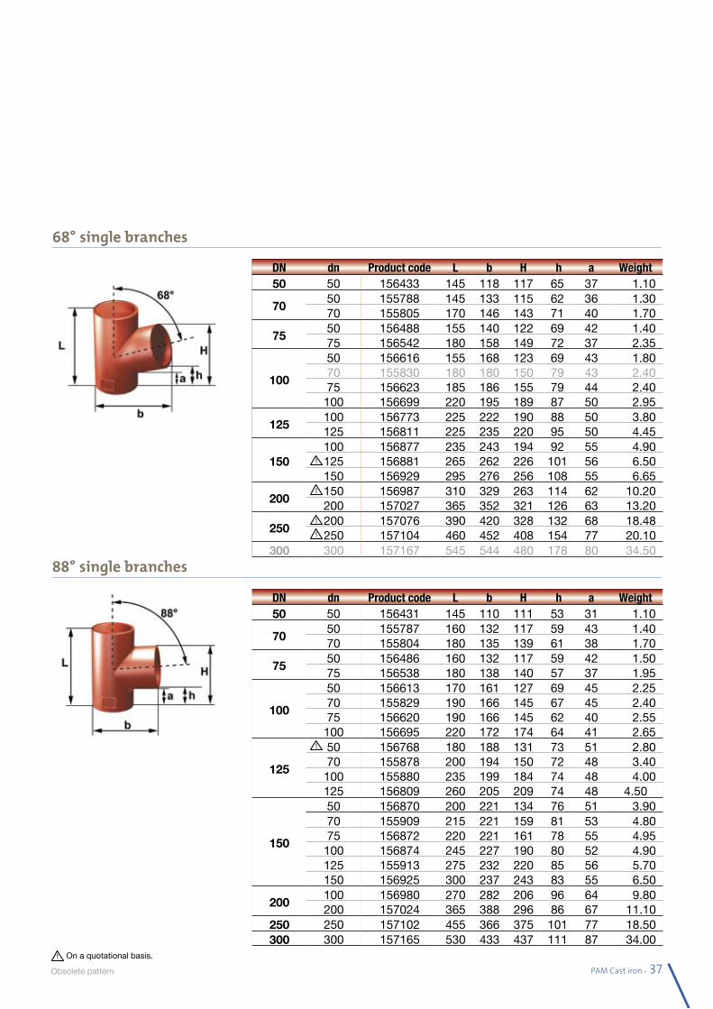
68° single branches
88° single branches
DN dn Product code L b H h a Weight50 50 156433 145 118 117 65 37 1.10
7050 155788 145 133 115 62 36 1.3070 155805 170 146 143 71 40 1.70
7550 156488 155 140 122 69 42 1.4075 156542 180 158 149 72 37 2.35
100
50 156616 155 168 123 69 43 1.8070 155830 180 180 150 79 43 2.4075 156623 185 186 155 79 44 2.40100 156699 220 195 189 87 50 2.95
125100 156773 225 222 190 88 50 3.80125 156811 225 235 220 95 50 4.45
150100 156877 235 243 194 92 55 4.90125 156881 265 262 226 101 56 6.50150 156929 295 276 256 108 55 6.65
200150 156987 310 329 263 114 62 10.20200 157027 365 352 321 126 63 13.20
250200 157076 390 420 328 132 68 18.48250 157104 460 452 408 154 77 20.10
300 300 157167 545 544 480 178 80 34.50
DN dn Product code L b H h a Weight50 50 156431 145 110 111 53 31 1.10
7050 155787 160 132 117 59 43 1.4070 155804 180 135 139 61 38 1.70
7550 156486 160 132 117 59 42 1.5075 156538 180 138 140 57 37 1.95
100
50 156613 170 161 127 69 45 2.2570 155829 190 166 145 67 45 2.4075 156620 190 166 145 62 40 2.55100 156695 220 172 174 64 41 2.65
125
50 156768 180 188 131 73 51 2.8070 155878 200 194 150 72 48 3.40100 155880 235 199 184 74 48 4.00125 156809 260 205 209 74 48 4.50
150
50 156870 200 221 134 76 51 3.9070 155909 215 221 159 81 53 4.8075 156872 220 221 161 78 55 4.95100 156874 245 227 190 80 52 4.90125 155913 275 232 220 85 56 5.70150 156925 300 237 243 83 55 6.50
200100 156980 270 282 206 96 64 9.80200 157024 365 388 296 86 67 11.10
250 250 157102 455 366 375 101 77 18.50300 300 157165 530 433 437 111 87 34.00
On a quotational basis.
Obsolete pa ttern
All dimensions are in mm and nominal weights in kg38 - PAM Cast iron
PAM SMU / ENSIGN®S
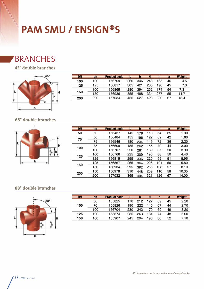
BRANCHES45° double branches
68° double branches
88° double branches
DN dn Product code L b H h a Weight100 100 156709 260 346 243 165 46 4.5125 125 156817 305 421 285 190 45 7.3
150100 156865 280 394 252 174 54 7,3150 156936 355 488 334 277 55 11,7
200 200 157034 455 627 428 280 67 18,4
DN dn Product code L b H h a Weight50 50 156437 145 178 118 64 35 1.30
75 50 156484 155 196 122 69 42 1.6075 156546 180 234 149 72 36 2.20
100 75 156609 185 262 155 79 44 3.00100 156707 220 281 189 87 50 3.90
125 100 156766 225 309 190 88 50 4.40125 156815 255 336 220 95 51 5.95
150 125 156867 265 364 226 101 56 5.80150 156934 295 392 256 108 57 8.10
200 150 156978 310 448 259 110 58 10.35200 157032 365 494 321 126 67 14.00
DN dn Product code L b H h a Weight
10050 155825 170 212 127 69 45 2.2070 155826 190 222 145 67 44 2.70100 156704 230 243 179 69 49 3.20
125 100 155874 235 263 184 74 48 5.00150 100 155907 245 294 190 80 52 7.10
PAM Cast iron - 39
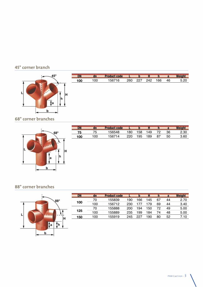
45° corner branch
68° corner branches
88° corner branches
DN dn Product code L b H h a Weight100 100 156716 260 227 242 166 46 5.20
DN dn Product code L b H h a Weight75 75 156548 180 158 149 72 36 2.30100 100 156714 220 195 189 87 50 3.60
DN dn Product code L b H h a Weight
10070 155839 190 166 145 67 44 2.70100 156712 230 177 179 69 44 3.40
12570 155888 200 194 150 72 49 5.00100 155889 235 199 184 74 48 5.00
150 100 155919 245 227 190 80 52 7.10
40 - PAM Cast iron
PAM SMU / ENSIGN®S
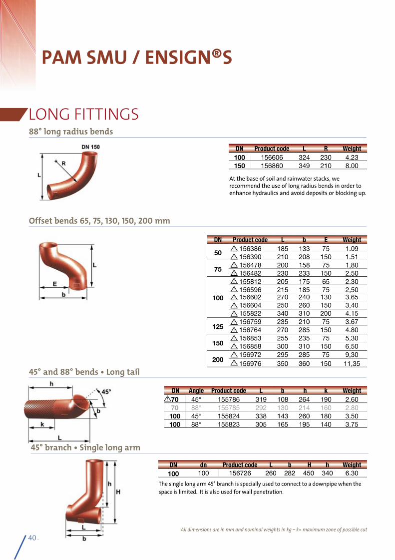
LONG FITTINGS88° long radius bends
45° and 88° bends • Long tail
At the base of soil and rainwater stacks, we recommend the use of long radius bends in order to enhance hydraulics and avoid deposits or blocking up.
DN Product code L R Weight100 156606 324 230 4.23150 156860 349 210 8.00
DN Product code L b E Weight
50156386 185 133 75 1.09156390 210 208 150 1.51
75156478 200 158 75 1,80156482 230 233 150 2,50
100
155812 205 175 65 2.30156596 215 185 75 2,50156602 270 240 130 3.65156604 250 260 150 3,40155822 340 310 200 4.15
125156759 235 210 75 3.67156764 270 285 150 4.80
150156853 255 235 75 5,30156858 300 310 150 6,50
200156972 295 285 75 9,30156976 350 360 150 11,35
DN Angle Product code L b h k Weight70 45° 155786 319 108 264 190 2.6070 88° 155785 292 130 214 160 2.80
100 45° 155824 338 143 260 180 3.50100 88° 155823 305 165 195 140 3.75
All dimensions are in mm and nominal weights in kg – k= maximum zone of possible cut
Offset bends 65, 75, 130, 150, 200 mm
45° branch • Single long arm
DN dn Product code L b H h Weight100 100 156726 260 282 450 340 6.30
The single long arm 45° branch is specially used to connect to a downpipe when the space is limited. It is also used for wall penetration.
PAM Cast iron - 41
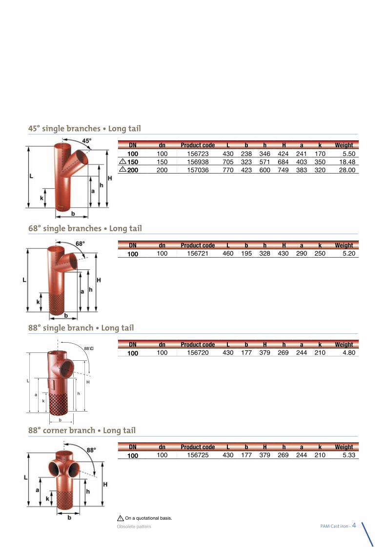
68° single branches • Long tail
88° single branch • Long tail
DN dn Product code L b h H a k Weight100 100 156723 430 238 346 424 241 170 5.50150 150 156938 705 323 571 684 403 350 18.48200 200 157036 770 423 600 749 383 320 28.00
DN dn Product code L b h H a k Weight100 100 156721 460 195 328 430 290 250 5.20
DN dn Product code L b H h a k Weight100 100 156720 430 177 379 269 244 210 4.80
88° corner branch • Long tailb
L
ka h
H
88ϒ�
45° single branches • Long tail
DN dn Product code L b H h a k Weight100 100 156725 430 177 379 269 244 210 5.33
On a quotational basis.
Obsolete pa ttern
42 - PAM Cast iron
PAM SMU / ENSIGN®S
CONNECTORS
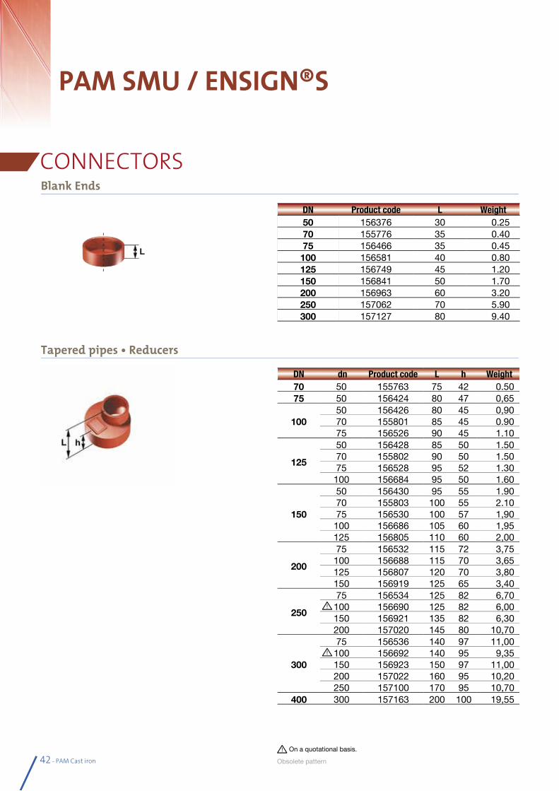
Tapered pipes • Reducers
DN dn Product code L h Weight70 50 155763 75 42 0.5075 50 156424 80 47 0,65
10050 156426 80 45 0,9070 155801 85 45 0.9075 156526 90 45 1.10
125
50 156428 85 50 1.5070 155802 90 50 1.5075 156528 95 52 1.30100 156684 95 50 1.60
150
50 156430 95 55 1.9070 155803 100 55 2.1075 156530 100 57 1,90100 156686 105 60 1,95125 156805 110 60 2,00
200
75 156532 115 72 3,75100 156688 115 70 3,65125 156807 120 70 3,80150 156919 125 65 3,40
250
75 156534 125 82 6,70100 156690 125 82 6,00150 156921 135 82 6,30200 157020 145 80 10,70
300
75 156536 140 97 11,00100 156692 140 95 9,35150 156923 150 97 11,00200 157022 160 95 10,20250 157100 170 95 10,70
400 300 157163 200 100 19,55
Blank Ends
DN Product code L Weight50 156376 30 0.2570 155776 35 0.4075 156466 35 0.45100 156581 40 0.80125 156749 45 1.20150 156841 50 1.70200 156963 60 3.20250 157062 70 5.90300 157127 80 9.40
On a quotational basis.
Obsolete pa ttern
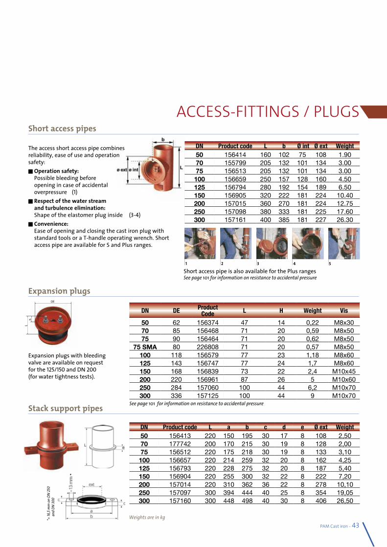
PAM Cast iron - 43
Stack support pipes
ACCESS-FITTINGS / PLUGS
DE
hL
1 2 53 4
DN Product code L a b c d e Ø ext Weight50 156413 220 150 195 30 17 8 108 2,5070 177742 200 170 215 30 19 8 128 2,0075 156512 220 175 218 30 19 8 133 3,10100 156657 220 214 259 32 20 8 162 4,25125 156793 220 228 275 32 20 8 187 5,40150 156904 220 255 300 32 22 8 222 7,20200 157014 220 310 362 36 22 8 278 10,10250 157097 300 394 444 40 25 8 354 19,05300 157160 300 448 498 40 30 8 406 26,50
DN DE Product Code L H Weight Vis
50 62 156374 47 14 0,22 M8x3070 85 156468 71 20 0,59 M8x5075 90 156464 71 20 0,62 M8x50
75 SMA 80 226808 71 20 0,57 M8x50100 118 156579 77 23 1,18 M8x60125 143 156747 77 24 1,7 M8x60150 168 156839 73 22 2,4 M10x45200 220 156961 87 26 5 M10x60250 284 157060 100 44 6,2 M10x70300 336 157125 100 44 9 M10x70
The access short access pipe combines reliability, ease of use and operation safety:n Operation safety:
Possible bleeding before opening in case of accidental overpressure =(1)
n Respect of the water stream and turbulence elimination: Shape of the elastomer plug inside = (3-4)
n Convenience: Ease of opening and closing the cast iron plug with standard tools or a T-handle operating wrench. Short access pipe are available for S and Plus ranges.
Short access pipe is also available for the Plus rangesSee page 101 for information on resistance to accidental pressure
Expansion plugs with bleeding valve are available on request for the 125/150 and DN 200 (for water tightness tests).
Expansion plugs
Weights are in kg
DN Product code L b Ø int Ø ext Weight50 156414 160 102 75 108 1.9070 155799 205 132 101 134 3.0075 156513 205 132 101 134 3.00100 156659 250 157 128 160 4.50125 156794 280 192 154 189 6.50150 156905 320 222 181 224 10.40200 157015 360 270 181 224 12.75250 157098 380 333 181 225 17.60300 157161 400 385 181 227 26.30
Short access pipes
See page 101 for information on resistance to accidental pressure
*= 16
,5 m
m o
n DN
250
and
DN 30
0
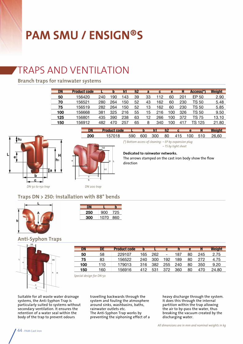
44 - PAM Cast iron
PAM SMU / ENSIGN®S
TRAPS AND VENTILATIONBranch traps for rainwater systems
Traps DN > 250: installation with 88° bends
All dimensions are in mm and nominal weights in kg
Anti-Syphon Traps
travelling backwards through the system and fouling the atmosphere around sinks, washbasins, baths, rainwater outlets etc.The Anti-Syphon Trap works by preventing the siphoning effect of a
Suitable for all waste water drainage systems, the Anti-Syphon Trap is particularly suited to systems without secondary ventilation. It ensures the retention of a water seal within the body of the trap to prevent odours
heavy discharge through the system. It does this through the internal partition within the trap allowing the air to by-pass the water, thus breaking the vacuum created by the discharging water.
DN Product code L b h1 h2 a c e H Access(*) Weight50 156420 240 190 143 39 33 112 60 201 EP 50 2.9070 156521 280 264 150 52 43 162 60 230 TS 50 5.4875 156519 282 264 150 52 13 162 60 230 TS 50 5.85100 156668 381 325 216 55 15 216 100 326 TS 50 9.50125 156801 435 390 238 63 12 266 100 372 TS 75 13.10150 156912 482 470 257 65 8 340 100 417 TS 125 21.80
DE
cb
Le
DE
h H
DN DE Product code b L c h e H Weight50 58 229107 165 262 - 187 80 245 2.7575 83 156522 240 300 192 189 80 272 4.75100 110 179013 316 382 255 240 80 350 9.20150 160 156916 412 531 372 360 80 470 24.80
DN Product code L b h1 h2 c e H Weight200 157018 590 600 300 80 415 100 510 26,60
(*) Bottom access of cleaning: – EP by expansion plug – TS by tight sheet
Dedicated to rainwater networks. The arrows stamped on the cast iron body show the flow direction
Special design for DN 50
DN 50 to 150 trap DN 200 trap
DN L b250 900 725300 1070 860
L
h2
H
h1
cb
e
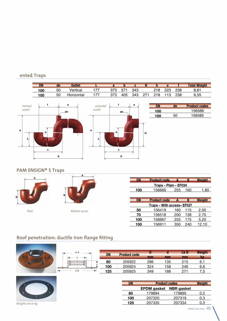
PAM Cast iron - 45
Vented Traps
Weights are in kg
DN dn Outlet L a b c H h e f Total Weight 100 50 Vertical 177 373 571 343 218 223 238 8,81100 50 Horizontal 177 373 405 343 271 218 113 238 6,55
PAM ENSIGN® S Traps
Roof penetration: ductile iron flange fitting
DN Product code A B WeightTraps – Plain – EF034
100 156666 255 160 1.80
DN Product code A B WeightTraps – With access– EF037
50 156419 160 115 2.0070 156518 200 138 2.70100 156667 255 175 5.20150 156911 350 240 12.10
DN Product codeD
mmd
mmLk Ø mm
Weight kg
80 205922 286 135 215 6,1100 205924 324 158 246 6,6125 205925 349 188 271 7,5
Plain Bottom access
DN Product codes WeightEPDM gasket NBR gasket
80 179894 179895 0.2100 207320 207319 0.3125 207335 207334 0.3
Horizontaloutlet
L
ha
c
b
f e
dn
H
Verticaloutlet
L
ha
c
b
f e
dn
DN dn Product codes100 156588100 50 156585
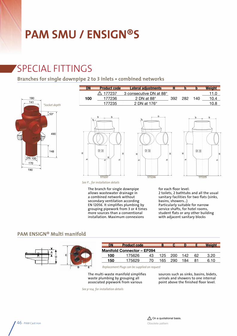
46 - PAM Cast iron
PAM SMU / ENSIGN®S
SPECIAL FITTINGSBranches for single downpipe 2 to 3 inlets • combined networks
PAM ENSIGN® Multi manifold
141
DN 100
180
170
190
148
53*
490
DN Product code Lateral adjustments H h b Weight
100177237 3 consecutive DN at 88°
392 282 140 11.0
177236 2 DN at 88° 10.4177235 2 DN at 176° 10.8*Socket depth
H
h H
h
H
b b
h b
b b
H
h h H
b b
H
h
H
h
177237
H
h H
h
H
b b
h
b b
b
H
h h H
b b
H
h
H
h
177236
H
h H
h
H
b b
h
b b
b
H
h h H
b b
H
h
H
h
177235
DN Product code B C D E WeightManifold Connector – EF094
100 175626 43 125 200 142 62 3.20150 175629 70 165 290 184 81 6.10
Replacement Plugs can be supplied on request
See P... for installation details
See p 104 for installation details
The branch for single downpipe allows wastewater drainage in a combined network without secondary ventilation according EN 12056. It simplifies plumbing by grouping pipework from 3 or 4 times more sources than a conventional installation. Maximum connexions
for each floor level:2 toilets, 2 bathtubs and all the usual sanitary facilities for two flats (sinks, basins, showers…)Particularly suitable for narrow service shafts, for hotel rooms, student flats or any other building with adjacent sanitary blocks
The multi-waste manifold simplifies waste plumbing by grouping all associated pipework from various
sources such as sinks, basins, bidets, urinals and showers to one internal point above the finished floor level.
On a quotational basis.
Obsolete pa ttern
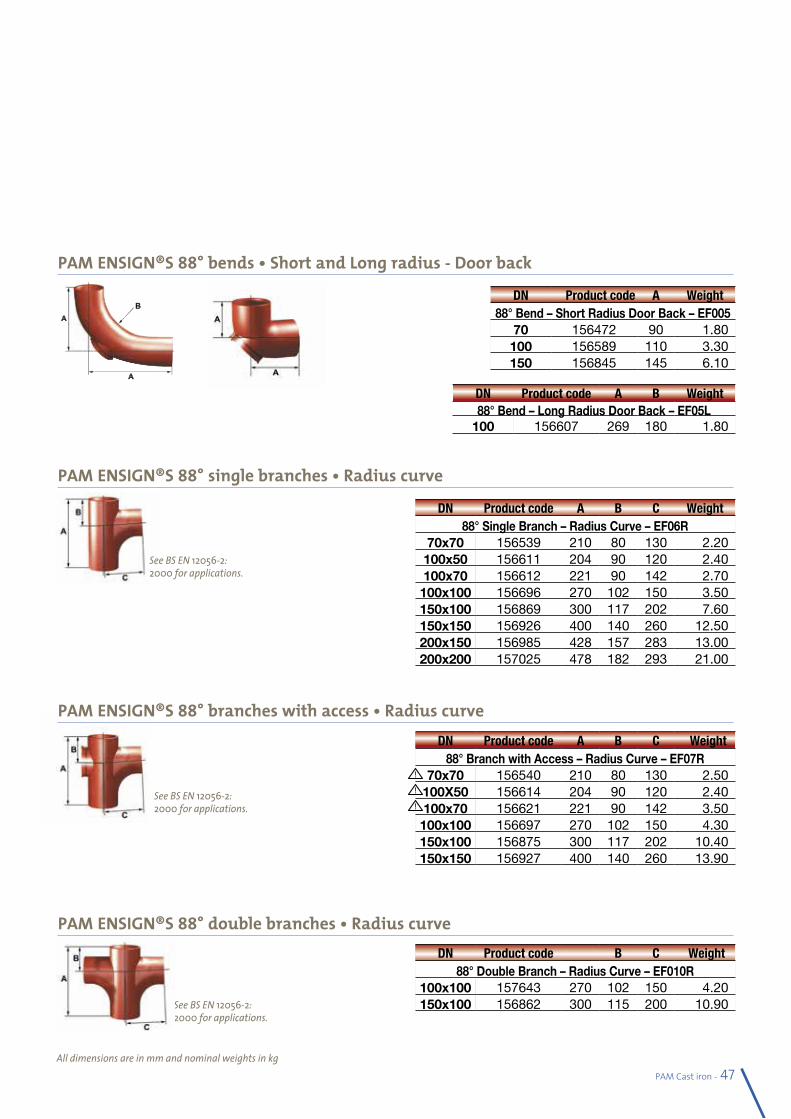
See BS EN 12056-2: 2000 for applications.
See BS EN 12056-2: 2000 for applications.
PAM Cast iron - 47
PAM ENSIGN®S 88° bends • Short and Long radius - Door back
PAM ENSIGN®S 88° single branches • Radius curve
PAM ENSIGN®S 88° branches with access • Radius curve
PAM ENSIGN®S 88° double branches • Radius curve
All dimensions are in mm and nominal weights in kg
DN Product code A Weight88° Bend – Short Radius Door Back – EF005
70 156472 90 1.80100 156589 110 3.30150 156845 145 6.10
DN Product code A B Weight88° Bend – Long Radius Door Back – EF05L
100 156607 269 180 1.80
DN Product code A B C Weight88° Single Branch – Radius Curve – EF06R
70x70 156539 210 80 130 2.20100x50 156611 204 90 120 2.40100x70 156612 221 90 142 2.70
100x100 156696 270 102 150 3.50150x100 156869 300 117 202 7.60150x150 156926 400 140 260 12.50200x150 156985 428 157 283 13.00200x200 157025 478 182 293 21.00
DN Product code A B C Weight88° Branch with Access – Radius Curve – EF07R
70x70 156540 210 80 130 2.50100X50 156614 204 90 120 2.40100x70 156621 221 90 142 3.50
100x100 156697 270 102 150 4.30150x100 156875 300 117 202 10.40150x150 156927 400 140 260 13.90
DN Product code B C Weight88° Double Branch – Radius Curve – EF010R
100x100 157643 270 102 150 4.20150x100 156862 300 115 200 10.90
See BS EN 12056-2: 2000 for applications.
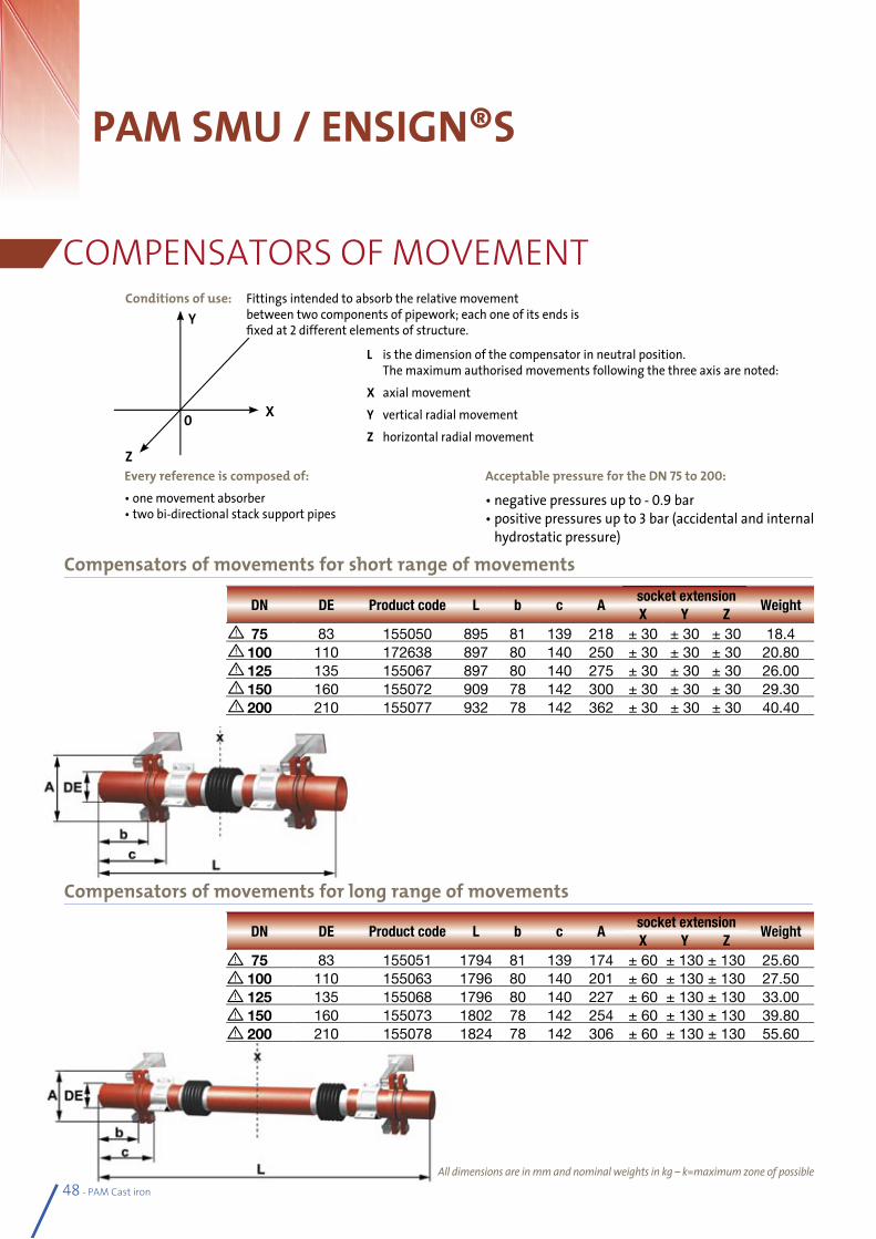
48 - PAM Cast iron
PAM SMU / ENSIGN®S
COMPENSATORS OF MOVEMENT
Compensators of movements for short range of movements
Compensators of movements for long range of movements
All dimensions are in mm and nominal weights in kg – k=maximum zone of possible
DN DE Product code L b c A socket extension
WeightX Y Z
75 83 155050 895 81 139 218 ± 30 ± 30 ± 30 18.4100 110 172638 897 80 140 250 ± 30 ± 30 ± 30 20.80125 135 155067 897 80 140 275 ± 30 ± 30 ± 30 26.00150 160 155072 909 78 142 300 ± 30 ± 30 ± 30 29.30200 210 155077 932 78 142 362 ± 30 ± 30 ± 30 40.40
DN DE Product code L b c A socket extension
WeightX Y Z
75 83 155051 1794 81 139 174 ± 60 ± 130 ± 130 25.60100 110 155063 1796 80 140 201 ± 60 ± 130 ± 130 27.50125 135 155068 1796 80 140 227 ± 60 ± 130 ± 130 33.00150 160 155073 1802 78 142 254 ± 60 ± 130 ± 130 39.80200 210 155078 1824 78 142 306 ± 60 ± 130 ± 130 55.60
Conditions of use: Fittings intended to absorb the relative movement between two components of pipework; each one of its ends is fixed at 2 different elements of structure.
Acceptable pressure for the DN 75 to 200:
• negative pressures up to - 0.9 bar• positive pressures up to 3 bar (accidental and internal
hydrostatic pressure)
Every reference is composed of:• one movement absorber • two bi-directional stack support pipes
L is the dimension of the compensator in neutral position. The maximum authorised movements following the three axis are noted:X axial movementY vertical radial movementZ horizontal radial movement
Z
X0
Y
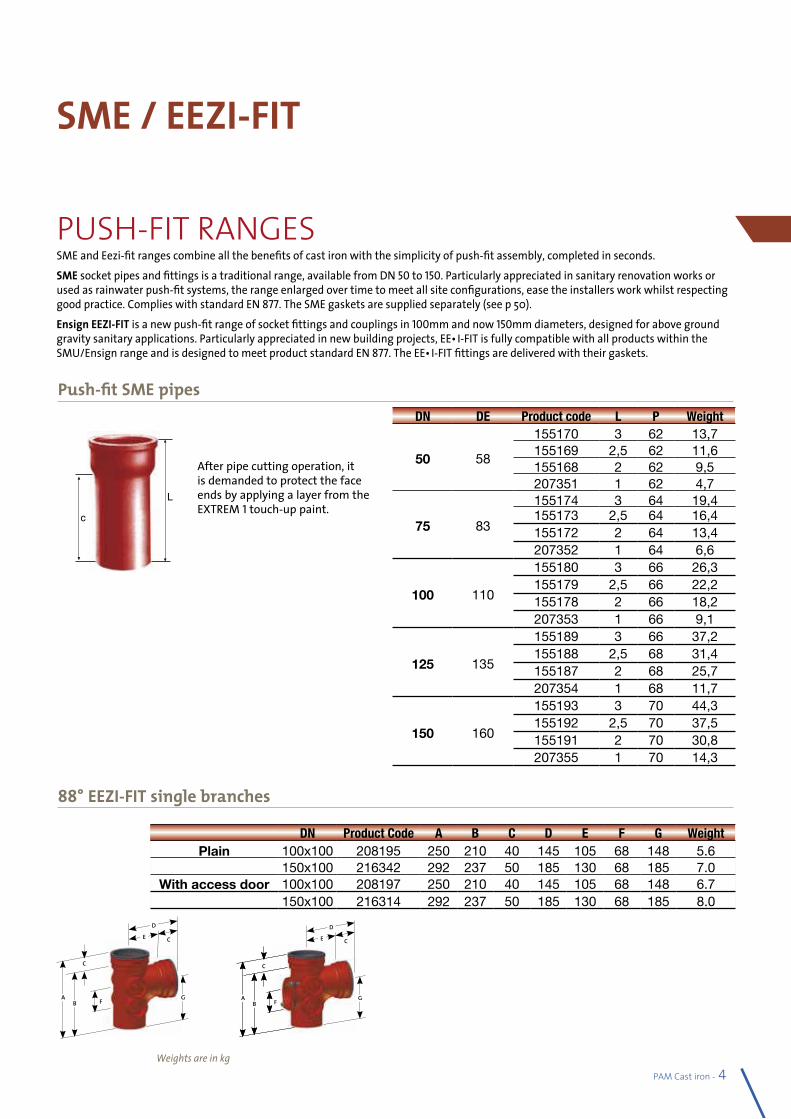
PAM Cast iron - 49
SME and Eezi-fit ranges combine all the benefits of cast iron with the simplicity of push-fit assembly, completed in seconds. SME socket pipes and fittings is a traditional range, available from DN 50 to 150. Particularly appreciated in sanitary renovation works or used as rainwater push-fit systems, the range enlarged over time to meet all site configurations, ease the installers work whilst respecting good practice. Complies with standard EN 877. The SME gaskets are supplied separately (see p 50).Ensign EEZI-FIT is a new push-fit range of socket fittings and couplings in 100mm and now 150mm diameters, designed for above ground gravity sanitary applications. Particularly appreciated in new building projects, EEZI-FIT is fully compatible with all products within the SMU/Ensign range and is designed to meet product standard EN 877. The EEZI-FIT fittings are delivered with their gaskets.
SME / EEZI-FIT
Weights are in kg
After pipe cutting operation, it is demanded to protect the face ends by applying a layer from the EXTREM 1 touch-up paint.
Push-fit SME pipesDN DE Product code L P Weight
50 58
155170 3 62 13,7155169 2,5 62 11,6155168 2 62 9,5207351 1 62 4,7
75 83
155174 3 64 19,4155173 2,5 64 16,4155172 2 64 13,4207352 1 64 6,6
100 110
155180 3 66 26,3155179 2,5 66 22,2155178 2 66 18,2207353 1 66 9,1
125 135
155189 3 66 37,2155188 2,5 68 31,4155187 2 68 25,7207354 1 68 11,7
150 160
155193 3 70 44,3155192 2,5 70 37,5155191 2 70 30,8207355 1 70 14,3
L
c
b
88° EEZI-FIT single branches
DN Product Code A B C D E F G WeightPlain 100x100 208195 250 210 40 145 105 68 148 5.6
150x100 216342 292 237 50 185 130 68 185 7.0With access door 100x100 208197 250 210 40 145 105 68 148 6.7
150x100 216314 292 237 50 185 130 68 185 8.0
G
C
D
E
A
C
B F A G
C
C
B FA
C
B F
D
E
PUSH-FIT RANGES
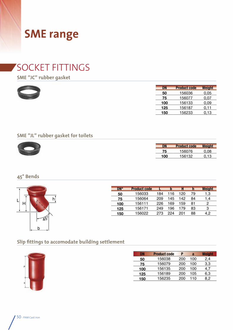
50 - PAM Cast iron
SME range
SME ”JC” rubber gasket
SME ”JL” rubber gasket for toilets
45° Bends
Slip fittings to accomodate building settlement
DN* Product code L b H h Weight50 156033 184 116 120 79 1,375 156064 209 145 142 84 1,4100 156111 226 169 159 81 2125 156171 249 196 179 83 3150 156022 273 224 201 88 4,2
DN Product code P a Weight50 156038 200 100 2,475 156079 200 100 3,3100 156135 200 100 4,7125 156189 200 105 6,3150 156235 200 110 8,2
DN Product code Weight50 156036 0,0575 156077 0,07100 156133 0,09125 156187 0,11150 156233 0,13
DN Product code Weight75 156076 0,08100 156132 0,13
LH
h
b
SOCKET FITTINGS
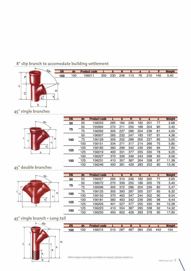
PAM Cast iron - 51
68° slip branch to accomodate building settlement
45° single branches
45° double branches
45° single branch • Long tail
DN dn Product code L b H h a c P Weight100 100 156011 350 230 248 113 76 210 140 5,40
DN dn Product code L b H h a c Weight 100 100 156015 510 287 487 384 230 442 154
DN dn Product code L b H h a c Weight 50 50 156053 265 184 246 182 201 77 2,68
7550 155994 270 211 250 188 204 80 3,4075 156092 305 227 286 204 239 81 4,00
10050 156007 265 232 247 183 197 81 4,3675 156129 305 252 286 205 237 85 5,00100 156151 334 271 317 214 266 75 5,80
125100 156185 360 299 342 239 290 84 7,60125 156019 400 331 377 255 330 78 9,25
150100 156227 370 326 346 243 298 93 9,56125 156231 410 357 387 264 338 87 11,38150 156246 450 381 426 283 253 80 13,36
DN dn Product code L b H h a c Weight 50 50 156057 265 310 246 182 200 77 3,65
7550 156072 270 339 250 186 205 79 3,4075 156096 305 372 286 204 239 80 5,47
10075 156125 305 393 287 205 237 85 6,32100 156155 370 463 347 244 302 90 8,54
125100 156181 360 463 342 239 290 98 9,44125 156205 401 527 377 255 330 84 12,28
150125 156223 410 554 387 265 338 92 14,32150 156250 450 602 426 283 378 90 17,60
a
cL
b
hH
c
b
L
ah
H
b
H
h
a
c
k
8
P
C
b
ha
L
Other shapes and angles available on request, please contact us.
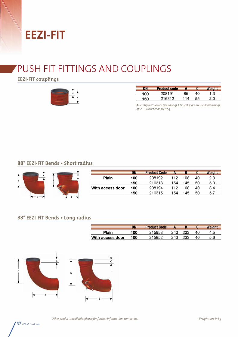
52 - PAM Cast iron
EEZI-FIT
Weights are in kg
EEZI-FIT couplings
88° EEZI-FIT Bends • Short radius
DN Product code A C Weight100 208191 85 40 1.3150 216312 114 55 2.0
DN Product Code A B C WeightPlain 100 208192 112 108 40 2.3
150 216313 154 145 50 5.0With access door 100 208194 112 108 40 3.4
150 216315 154 145 50 5.7
DN Product Code A B C WeightPlain 100 215953 243 233 40 4.5
With access door 100 215952 243 233 40 5.6
C
A
A
B
C
A
B
C
88° EEZI-FIT Bends • Long radius
Assembly instructions (see page 95 ). Gasket spare are available in bags of 10 – Product code 208204.
A
B
C
C
A
B
PUSH FIT FITTINGS AND COUPLINGS
Other products available, please for further information, contact us.
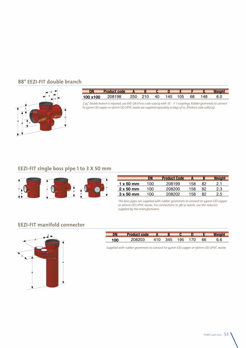
PAM Cast iron - 53
EEZI-FIT single boss pipe 1 to 3 X 50 mm
EEZI-FIT manifold connector
88° EEZI-FIT double branch
DN Product Code A B Weight1 x 50 mm 100 208199 158 82 2.12 x 50 mm 100 208200 158 82 2.33 x 50 mm 100 208202 158 82 2.5
DN Product code A B C D E Weight100 208203 410 345 195 170 66 6.6
The boss pipes are supplied with rubber grommets to connect to 54mm OD copper or 56mm OD UPVC waste. For connections to 38/32 waste, use the reducers supplied by the manufacturers.
If 45° double branch is required, use ENSIGN EF010 code 03009 with EEZI-FIT couplings. Rubber grommets to connect to 54mm OD copper or 56mm OD UPVC waste are supplied separately in bags of 10. (Product code 208205).
Supplied with rubber grommets to connect to 54mm OD copper or 56mm OD UPVC waste.
DN Product code A B C D E F G Weight100 x100 208198 250 210 40 145 105 68 148 6.0
G
C
D
E
A
C
B F
AB
A
B
B
A
C
D
E
B
A
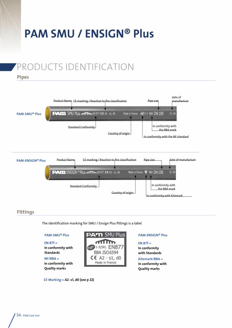
54 - PAM Cast iron 54 - PAM Cast iron
PAM SMU / ENSIGN® Plus
PAM-SMU® Plus
EN 877 = In conformity with Standards
NF/BBA = In conformity with Quality marks
PAM-ENSIGN® Plus
EN 877 = In conformity with Standards
Kitemark/BBA = In conformity with Quality marks
Pipes
Fittings
PRODUCTS IDENTIFICATION
The identification marking for SMU / Ensign Plus fittings is a label.
CE Marking = A2 -s1, d0 (see p 22)
PAM-SMU® Plus
PAM-ENSIGN® Plus
Country of originIn conformity with Kitemark
In conformity with the BBA mark
Standard Conformity
Product Name Pipe sizeCE marking / Reaction to fire classification date of manufacture
Country of originIn conformity with the NF standard
In conformity with the BBA mark
Standard Conformity
Product Namedate of manufacturePipe sizeCE marking / Reaction to fire classification
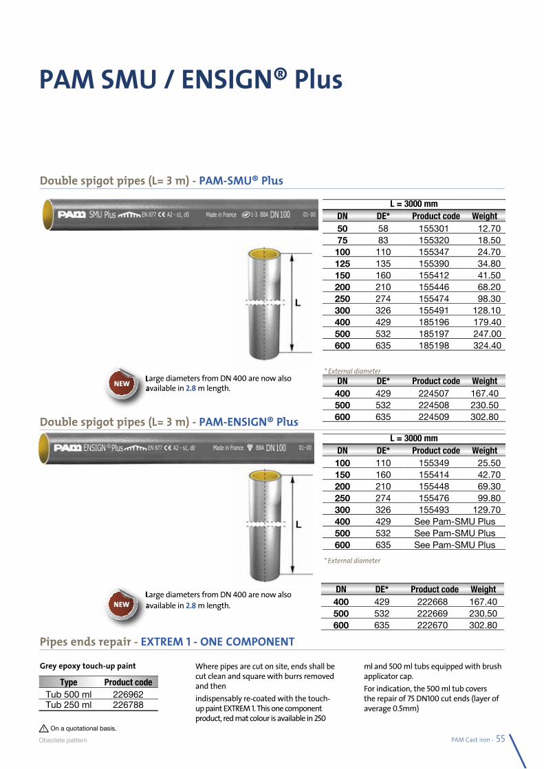
PAM Cast iron - 55
PAM SMU / ENSIGN® Plus
Double spigot pipes (L= 3 m) - PAM-SMU® Plus
L = 3000 mmDN DE* Product code Weight50 58 155301 12.7075 83 155320 18.50100 110 155347 24.70125 135 155390 34.80150 160 155412 41.50200 210 155446 68.20250 274 155474 98.30300 326 155491 128.10400 429 185196 179.40500 532 185197 247.00600 635 185198 324.40
L = 3000 mmDN DE* Product code Weight100 110 155349 25.50150 160 155414 42.70200 210 155448 69.30250 274 155476 99.80300 326 155493 129.70400 429 See Pam-SMU Plus500 532 See Pam-SMU Plus600 635 See Pam-SMU Plus
* External diameter
* External diameter
Double spigot pipes (L= 3 m) - PAM-ENSIGN® Plus
Pipes ends repair - EXTREM 1 - ONE COMPONENT
On a quotational basis.
Obsolete pa ttern
Grey epoxy touch-up paint Where pipes are cut on site, ends shall be cut clean and square with burrs removed and thenindispensably re-coated with the touch-up paint EXTREM 1. This one component product, red mat colour is available in 250
ml and 500 ml tubs equipped with brush applicator cap. For indication, the 500 ml tub covers the repair of 75 DN100 cut ends (layer of average 0.5mm)
Type Product codeTub 500 ml 226962Tub 250 ml 226788
DN DE* Product code Weight400 429 224507 167.40500 532 224508 230.50600 635 224509 302.80
DN DE* Product code Weight400 429 222668 167.40500 532 222669 230.50600 635 222670 302.80
Large diameters from DN 400 are now also available in 2.8 m length.
Large diameters from DN 400 are now also available in 2.8 m length.
Large diameters from DN available in NEW
Large diameters from DN available in NEW
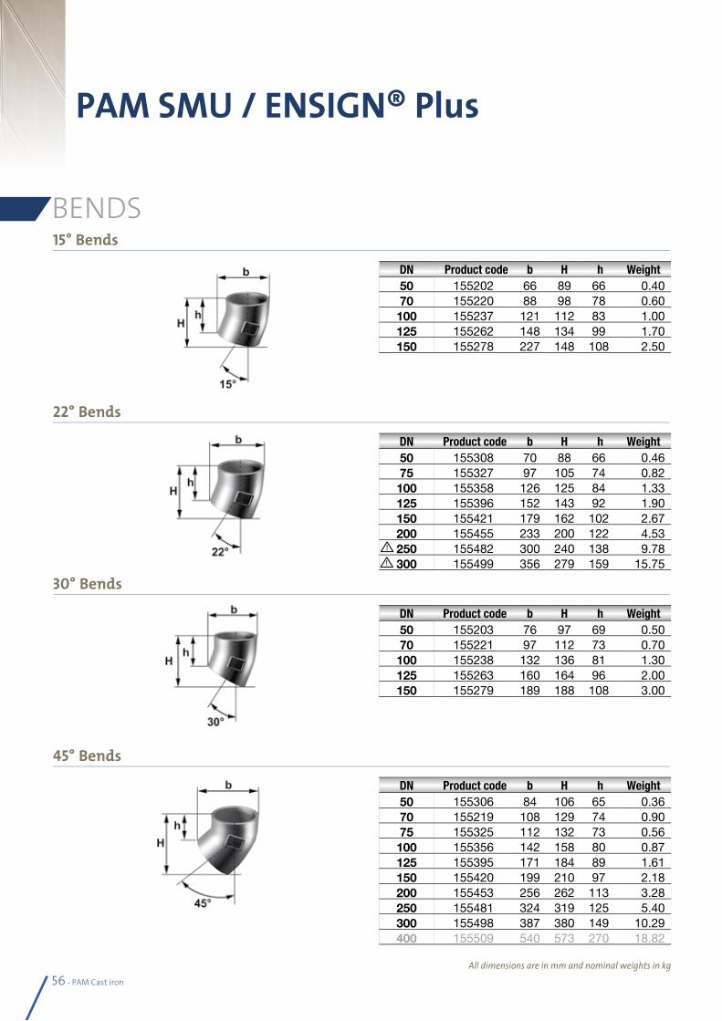
56 - PAM Cast iron
15° Bends
22° Bends
30° Bends
45° Bends
PAM SMU / ENSIGN® Plus
BENDS
All dimensions are in mm and nominal weights in kg
DN Product code b H h Weight50 155202 66 89 66 0.4070 155220 88 98 78 0.60100 155237 121 112 83 1.00125 155262 148 134 99 1.70150 155278 227 148 108 2.50
DN Product code b H h Weight50 155308 70 88 66 0.4675 155327 97 105 74 0.82100 155358 126 125 84 1.33125 155396 152 143 92 1.90150 155421 179 162 102 2.67200 155455 233 200 122 4.53250 155482 300 240 138 9.78300 155499 356 279 159 15.75
DN Product code b H h Weight50 155203 76 97 69 0.5070 155221 97 112 73 0.70100 155238 132 136 81 1.30125 155263 160 164 96 2.00150 155279 189 188 108 3.00
DN Product code b H h Weight50 155306 84 106 65 0.3670 155219 108 129 74 0.9075 155325 112 132 73 0.56100 155356 142 158 80 0.87125 155395 171 184 89 1.61150 155420 199 210 97 2.18200 155453 256 262 113 3.28250 155481 324 319 125 5.40300 155498 387 380 149 10.29400 155509 540 573 270 18.82
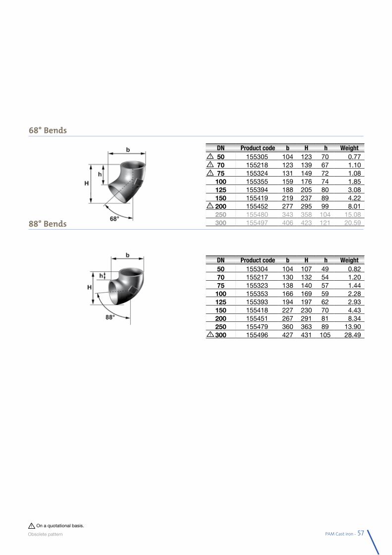
PAM Cast iron - 57
68° Bends
88° Bends
DN Product code b H h Weight50 155305 104 123 70 0.7770 155218 123 139 67 1.1075 155324 131 149 72 1.08100 155355 159 176 74 1.85125 155394 188 205 80 3.08150 155419 219 237 89 4.22200 155452 277 295 99 8.01250 155480 343 358 104 15.08300 155497 406 423 121 20.59
DN Product code b H h Weight50 155304 104 107 49 0.8270 155217 130 132 54 1.2075 155323 138 140 57 1.44100 155353 166 169 59 2.28125 155393 194 197 62 2.93150 155418 227 230 70 4.43200 155451 267 291 81 8.34250 155479 360 363 89 13.90300 155496 427 431 105 28.49
On a quotational basis.
Obsolete pa ttern
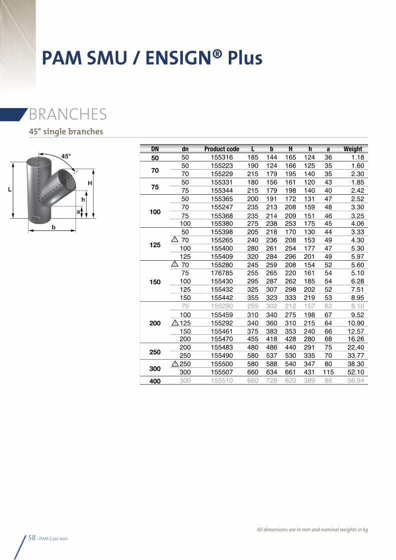
58 - PAM Cast iron
PAM SMU / ENSIGN® Plus
BRANCHES
All dimensions are in mm and nominal weights in kg
45° single branches
DN dn Product code L b H h a Weight50 50 155316 185 144 165 124 36 1.18
7050 155223 190 124 166 125 35 1.6070 155229 215 179 195 140 35 2.30
7550 155331 180 156 161 120 43 1.8575 155344 215 179 198 140 40 2.42
100
50 155365 200 191 172 131 47 2.5270 155247 235 213 208 159 48 3.3075 155368 235 214 209 151 46 3.25100 155380 275 238 253 175 45 4.06
125
50 155398 205 218 170 130 44 3.3370 155265 240 236 208 153 49 4.30100 155400 280 261 254 177 47 5.30125 155409 320 284 296 201 49 5.97
150
70 155280 245 259 208 154 52 5.6075 176785 255 265 220 161 54 5.10100 155430 295 287 262 185 54 6.28125 155432 325 307 298 202 52 7.51150 155442 355 323 333 219 53 8.95
200
70 155290 255 302 212 157 62 8.10100 155459 310 340 275 198 67 9.52125 155292 340 360 310 215 64 10.90150 155461 375 383 353 240 66 12.57200 155470 455 418 428 280 68 16.26
250200 155483 480 486 440 291 75 22,40250 155490 580 537 530 335 70 33.77
300250 155500 580 588 540 347 80 38.30300 155507 660 634 661 431 115 52.10
400 300 155510 660 728 620 389 86 56.94
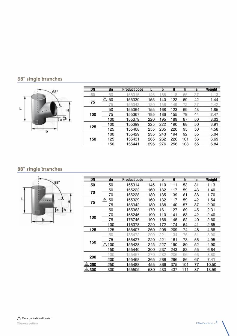
PAM Cast iron - 59
68° single branches
88° single branches
DN dn Product code L b H h a Weight50 50 155315 145 188 118 65 37 1.13
7550 155330 155 140 122 69 42 1.4475 155343 180 158 149 72 37 2.42
10050 155364 155 168 123 69 43 1.8575 155367 185 186 155 79 44 2.47100 155379 220 195 189 87 50 3.03
125100 155399 225 222 190 88 50 3.91125 155408 255 235 220 95 50 4.58
150100 155429 235 243 194 92 55 5.04125 155431 265 262 226 101 56 6.69150 155441 295 276 256 108 55 6.84
DN dn Product code L b H h a Weight50 50 155314 145 110 111 53 31 1.13
7050 155222 160 132 117 59 43 1.4070 155228 180 135 139 61 38 1.70
7550 155329 160 132 117 59 42 1.5475 155342 180 138 140 57 37 2.00
100
50 155363 170 161 127 69 45 2.3170 155246 190 110 141 63 42 2.4075 176746 190 166 145 62 40 2.60100 115378 220 172 174 64 41 2,65
125 125 155407 260 205 209 74 48 4.58
150
50 185472 200 221 134 76 51 3.9075 155427 220 221 161 78 55 4,95100 155428 245 227 190 80 52 4.90150 155440 300 237 243 83 55 6.84
200100 155457 270 282 206 96 66 8.80200 155468 365 288 296 86 67 7.41
250 250 155488 455 366 375 101 77 10.50300 300 155505 530 433 437 111 87 13.59
On a quotational basis.
Obsolete pa ttern
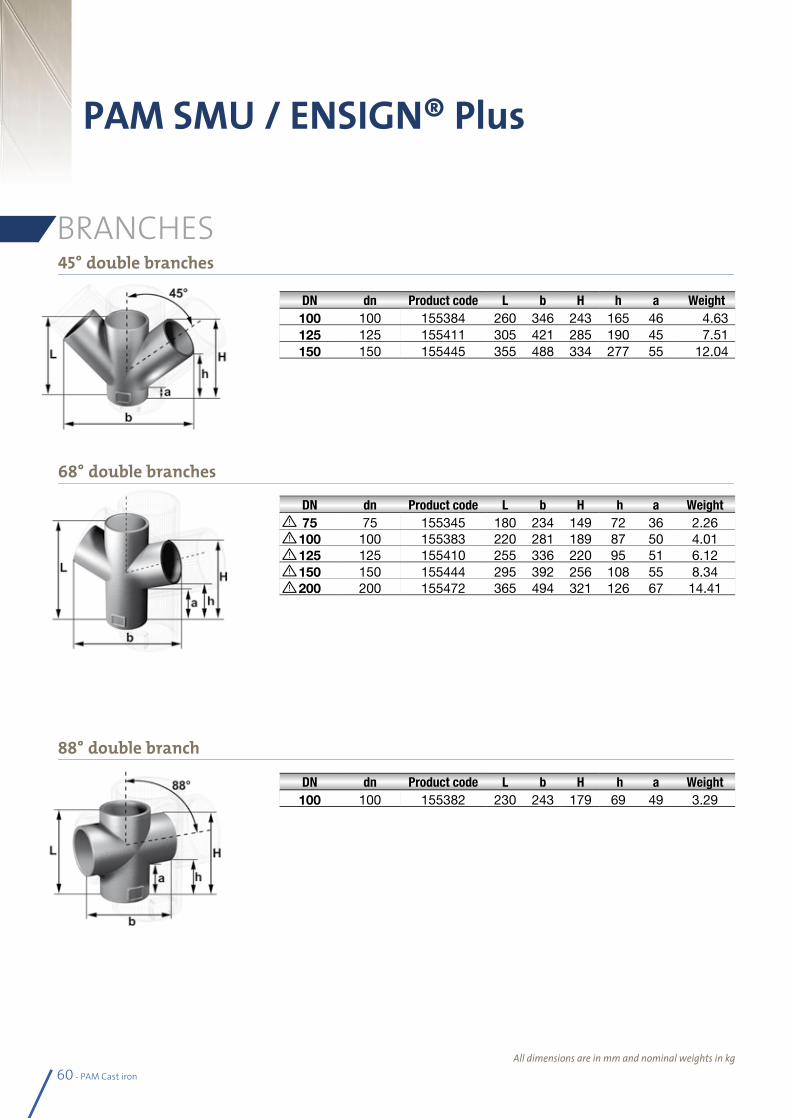
68° double branches
60 - PAM Cast iron
45° double branches
PAM SMU / ENSIGN® Plus
All dimensions are in mm and nominal weights in kg
DN dn Product code L b H h a Weight75 75 155345 180 234 149 72 36 2.26100 100 155383 220 281 189 87 50 4.01125 125 155410 255 336 220 95 51 6.12150 150 155444 295 392 256 108 55 8.34200 200 155472 365 494 321 126 67 14.41
DN dn Product code L b H h a Weight100 100 155384 260 346 243 165 46 4.63125 125 155411 305 421 285 190 45 7.51150 150 155445 355 488 334 277 55 12.04
DN dn Product code L b H h a Weight100 100 155382 230 243 179 69 49 3.29
88° double branch
BRANCHES
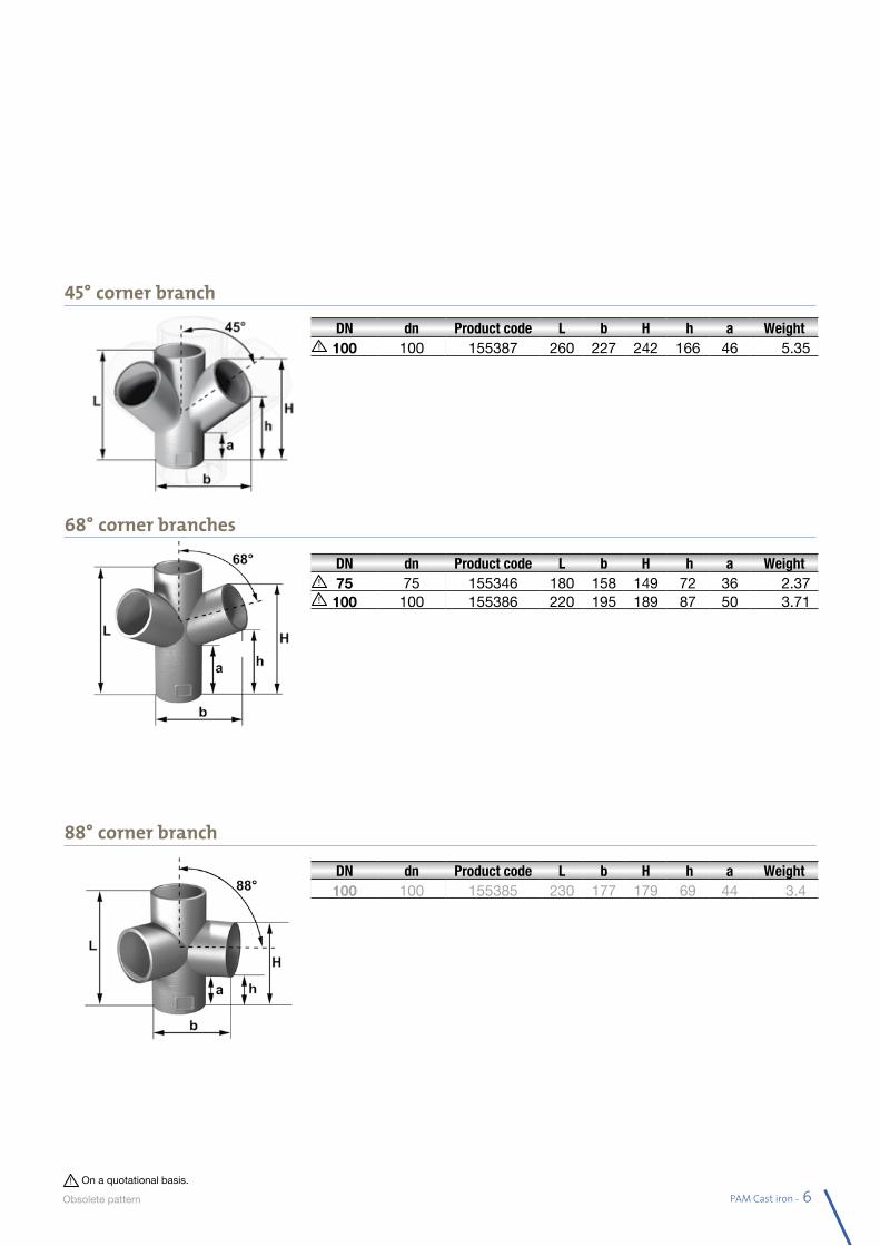
PAM Cast iron - 61
DN dn Product code L b H h a Weight100 100 155385 230 177 179 69 44 3.4
DN dn Product code L b H h a Weight100 100 155387 260 227 242 166 46 5.35
45° corner branch
88° corner branch
68° corner branches
DN dn Product code L b H h a Weight75 75 155346 180 158 149 72 36 2.37100 100 155386 220 195 189 87 50 3.71
On a quotational basis.
Obsolete pa ttern
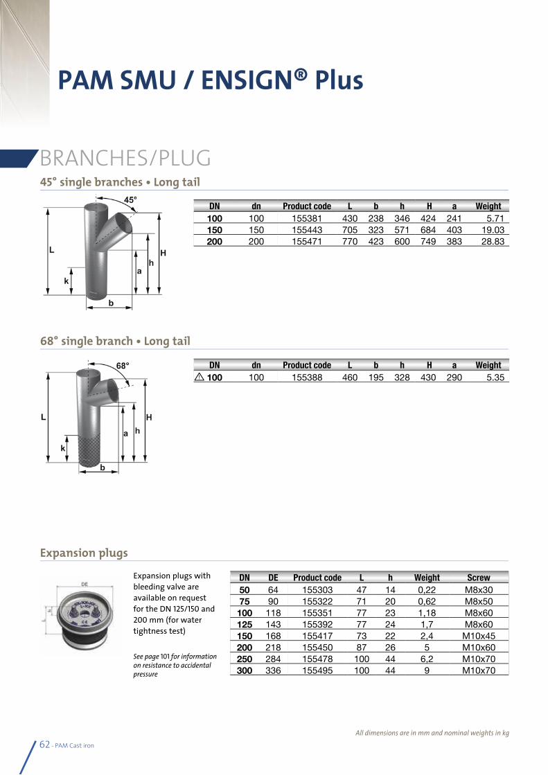
62 - PAM Cast iron
45° single branches • Long tail
68° single branch • Long tail
PAM SMU / ENSIGN® Plus
BRANCHES/PLUG
All dimensions are in mm and nominal weights in kg
Expansion plugs
DN dn Product code L b h H a Weight100 100 155381 430 238 346 424 241 5.71150 150 155443 705 323 571 684 403 19.03200 200 155471 770 423 600 749 383 28.83
DN DE Product code L h Weight Screw50 64 155303 47 14 0,22 M8x3075 90 155322 71 20 0,62 M8x50100 118 155351 77 23 1,18 M8x60125 143 155392 77 24 1,7 M8x60150 168 155417 73 22 2,4 M10x45200 218 155450 87 26 5 M10x60250 284 155478 100 44 6,2 M10x70300 336 155495 100 44 9 M10x70
Expansion plugs with bleeding valve are available on request for the DN 125/150 and 200 mm (for water tightness test)
See page 101 for information on resistance to accidental pressure
DN dn Product code L b h H a Weight100 100 155388 460 195 328 430 290 5.35
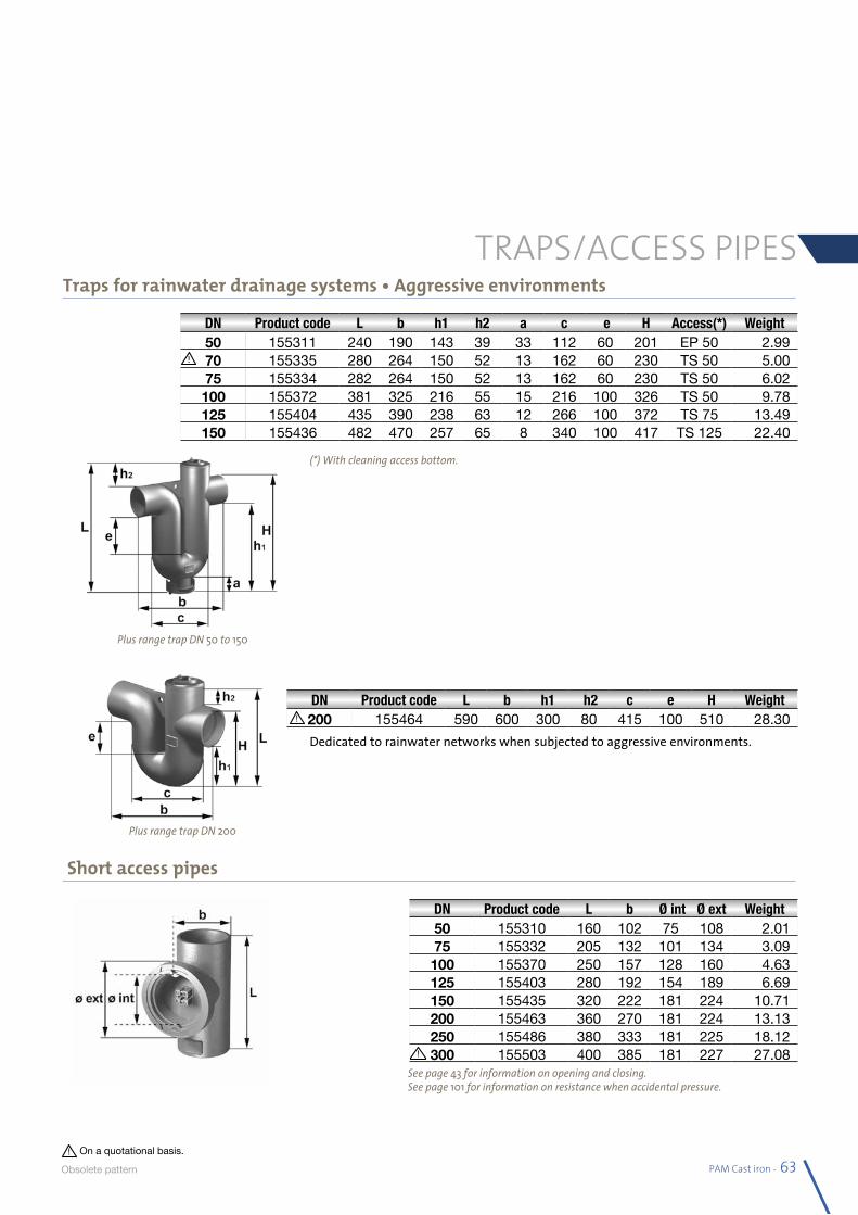
PAM Cast iron - 63
TRAPS/ACCESS PIPESTraps for rainwater drainage systems • Aggressive environments
Short access pipes
DN Product code L b h1 h2 a c e H Access(*) Weight50 155311 240 190 143 39 33 112 60 201 EP 50 2.9970 155335 280 264 150 52 13 162 60 230 TS 50 5.0075 155334 282 264 150 52 13 162 60 230 TS 50 6.02100 155372 381 325 216 55 15 216 100 326 TS 50 9.78125 155404 435 390 238 63 12 266 100 372 TS 75 13.49150 155436 482 470 257 65 8 340 100 417 TS 125 22.40
DN Product code L b Ø int Ø ext Weight50 155310 160 102 75 108 2.0175 155332 205 132 101 134 3.09100 155370 250 157 128 160 4.63125 155403 280 192 154 189 6.69150 155435 320 222 181 224 10.71200 155463 360 270 181 224 13.13250 155486 380 333 181 225 18.12300 155503 400 385 181 227 27.08
(*) With cleaning access bottom.
Dedicated to rainwater networks when subjected to aggressive environments.
DN Product code L b h1 h2 c e H Weight200 155464 590 600 300 80 415 100 510 28.30
Plus range trap DN 50 to 150
Plus range trap DN 200
See page 43 for information on opening and closing.See page 101 for information on resistance when accidental pressure.
On a quotational basis.
Obsolete pa ttern
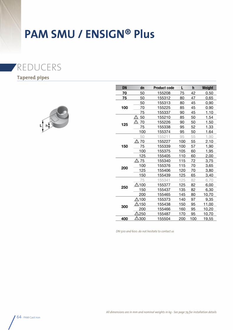
64 - PAM Cast iron
Tapered pipes
PAM SMU / ENSIGN® Plus
REDUCERS
DN dn Product code L h Weight70 50 155208 75 42 0.5075 50 155312 80 47 0,65
10050 155313 80 45 0,9070 155225 85 45 0.9075 155337 90 45 1.10
125
50 155210 85 50 1.5470 155226 90 50 1.5075 155338 95 52 1.33100 155374 95 50 1.64
150
50 155211 95 55 1,9070 155227 100 55 2.1075 155339 100 57 1,90100 155375 105 60 1,95125 155405 110 60 2,00
200
75 155340 115 72 3,75100 155376 115 70 3,65125 155406 120 70 3,80150 155439 125 65 3,40
250
75 155341 125 82 6,70100 155377 125 82 6,00150 155437 135 82 6,30200 155465 145 80 10,70
300
100 155373 140 97 9,35150 155438 150 95 11,00200 155466 160 95 10,20250 155487 170 95 10,70
400 300 155504 200 100 19,55
DN 500 and 600: do not hesitate to contact us
All dimensions are in mm and nominal weights in kg - See page 79 for installation details
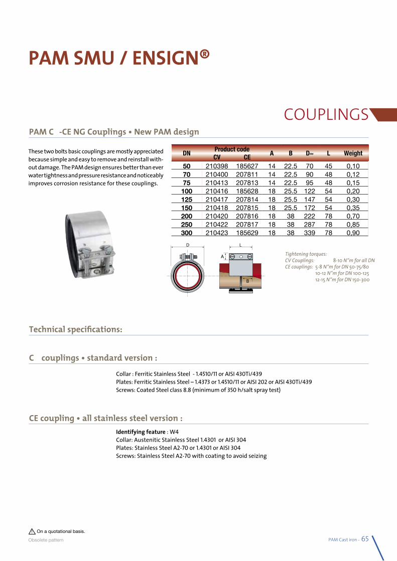
PAM Cast iron - 65
PAM SMU / ENSIGN®
COUPLINGSPAM CV-CE NG Couplings • New PAM design
CV couplings • standard version :
Technical specifications:
CE coupling • all stainless steel version :
Collar : Ferritic Stainless Steel - 1.4510/11 or AISI 430Ti/439Plates: Ferritic Stainless Steel – 1.4373 or 1.4510/11 or AISI 202 or AISI 430Ti/439Screws: Coated Steel class 8.8 (minimum of 350 h/salt spray test)
Identifying feature : W4Collar: Austenitic Stainless Steel 1.4301 or AISI 304Plates: Stainless Steel A2-70 or 1.4301 or AISI 304Screws: Stainless Steel A2-70 with coating to avoid seizing
These two bolts basic couplings are mostly appreciated because simple and easy to remove and reinstall with-out damage. The PAM design ensures better than ever water tightness and pressure resistance and noticeably improves corrosion resistance for these couplings.
Tightening torques:CV Couplings: 8-10 N•m for all DNCE couplings: 5-8 N•m for DN 50-75/80 10-12 N•m for DN 100-125 12-15 N•m for DN 150-300
DNProduct code
A B D≈ L WeightCV CE
50 210398 185627 14 22.5 70 45 0,1070 210400 207811 14 22.5 90 48 0,1275 210413 207813 14 22.5 95 48 0,15100 210416 185628 18 25.5 122 54 0,20125 210417 207814 18 25.5 147 54 0,30150 210418 207815 18 25.5 172 54 0,35200 210420 207816 18 38 222 78 0,70250 210422 207817 18 38 287 78 0,85300 210423 185629 18 38 339 78 0,90
On a quotational basis.
Obsolete pa ttern
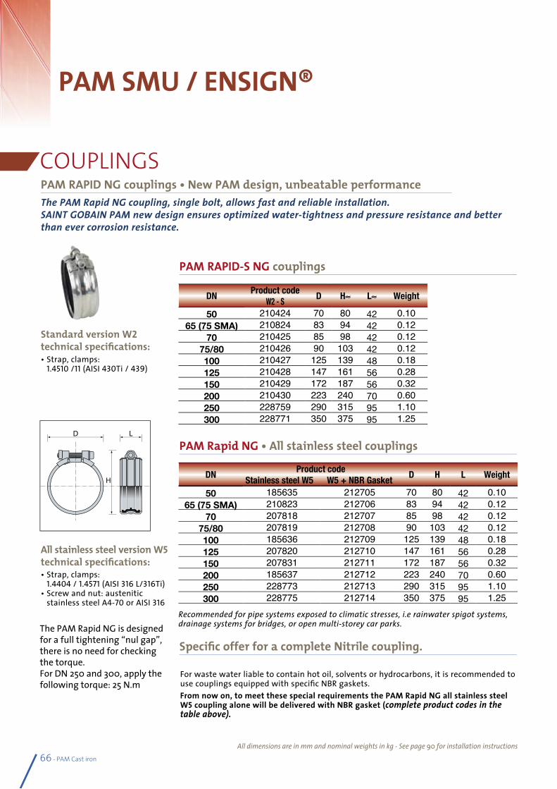
DNProduct code
D H L Weight Stainless steel W5 W5 + NBR Gasket
50 185635 212705 70 80 42 0.1065 (75 SMA) 210823 212706 83 94 42 0.12
70 207818 212707 85 98 42 0.1275/80 207819 212708 90 103 42 0.12100 185636 212709 125 139 48 0.18125 207820 212710 147 161 56 0.28150 207831 212711 172 187 56 0.32200 185637 212712 223 240 70 0.60250 228773 212713 290 315 95 1.10300 228775 212714 350 375 95 1.25
ThePAMRapidNGcoupling,singlebolt,allowsfastandreliableinstallation.SAINTGOBAINPAMnewdesignensuresoptimizedwater-tightnessandpressureresistanceandbetterthanevercorrosionresistance.
For waste water liable to contain hot oil, solvents or hydrocarbons, it is recommended to use couplings equipped with specific NBR gaskets. From now on, to meet these special requirements the PAM Rapid NG all stainless steel W5 coupling alone will be delivered with NBR gasket (completeproductcodesinthetableabove).
• Strap, clamps: 1.4510 /11 (AISI 430Ti / 439)
• Strap, clamps: 1.4404 / 1.4571 (AISI 316 L/316Ti)
• Screw and nut: austenitic stainless steel A4-70 or AISI 316
66 - PAM Cast iron
PAM SMU / ENSIGN®
COUPLINGS
PAM RAPID-S NG couplings
PAM RAPID NG couplings • New PAM design, unbeatable performance
PAM Rapid NG • All stainless steel couplings
Specific offer for a complete Nitrile coupling.
Standard version W2 technical specifications:
All stainless steel version W5 technical specifications:
All dimensions are in mm and nominal weights in kg - See page 90 for installation instructions
DNProduct code
D H≈ L≈ WeightW2 - S
50 210424 70 80 42 0.1065 (75 SMA) 210824 83 94 42 0.12
70 210425 85 98 42 0.1275/80 210426 90 103 42 0.12100 210427 125 139 48 0.18125 210428 147 161 56 0.28150 210429 172 187 56 0.32200 210430 223 240 70 0.60250 228759 290 315 95 1.10300 228771 350 375 95 1.25
The PAM Rapid NG is designed for a full tightening “nul gap”, there is no need for checking the torque. For DN 250 and 300, apply the following torque: 25 N.m
Recommended for pipe systems exposed to climatic stresses, i.e rainwater spigot systems, drainage systems for bridges, or open multi-storey car parks.
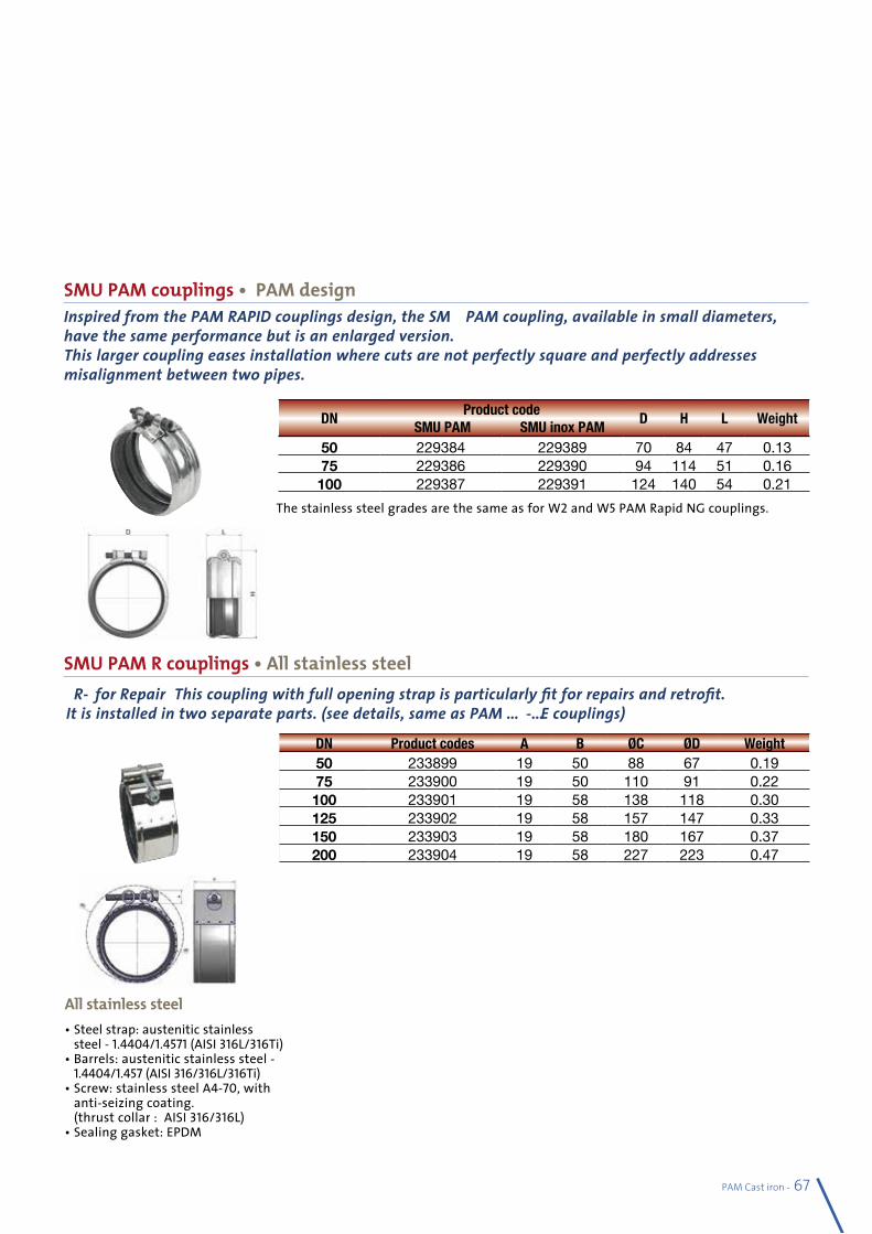
PAM Cast iron - 67
SMU PAM couplings • PAM design
SMU PAM R couplings • All stainless steel“R”forRepair:Thiscouplingwithfullopeningstrapisparticularlyfitforrepairsandretrofit.Itisinstalledintwoseparateparts.(seedetails,sameasPAMCV-CEcouplings)
• Steel strap: austenitic stainless steel - 1.4404/1.4571 (AISI 316L/316Ti)
• Barrels: austenitic stainless steel - 1.4404/1.457 (AISI 316/316L/316Ti)
• Screw: stainless steel A4-70, with anti-seizing coating. (thrust collar : AISI 316/316L)
• Sealing gasket: EPDM
All stainless steel
DNProduct code
D H L Weight SMU PAM SMU inox PAM
50 229384 229389 70 84 47 0.1375 229386 229390 94 114 51 0.16100 229387 229391 124 140 54 0.21
InspiredfromthePAMRAPIDcouplingsdesign,theSMUPAMcoupling,availableinsmalldiameters,havethesameperformancebutisanenlargedversion.Thislargercouplingeasesinstallationwherecutsarenotperfectlysquareandperfectlyaddressesmisalignmentbetweentwopipes.
DN Product codes A B ØC ØD Weight50 233899 19 50 88 67 0.1975 233900 19 50 110 91 0.22100 233901 19 58 138 118 0.30125 233902 19 58 157 147 0.33150 233903 19 58 180 167 0.37200 233904 19 58 227 223 0.47
The stainless steel grades are the same as for W2 and W5 PAM Rapid NG couplings.
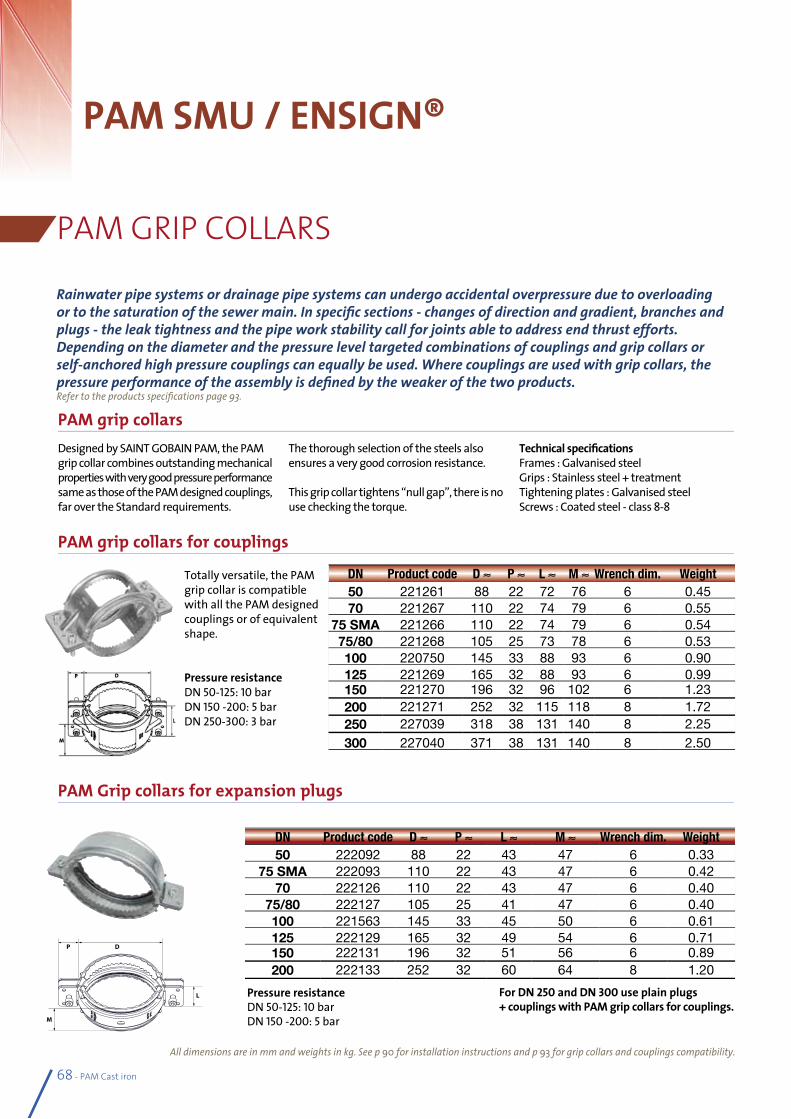
All dimensions are in mm and weights in kg. See p 90 for installation instructions and p 93 for grip collars and couplings compatibility.
68 - PAM Cast iron
PAM SMU / ENSIGN®
PAM GRIP COLLARS
PAM grip collars
PAM grip collars for couplings
PAM Grip collars for expansion plugs
Designed by SAINT GOBAIN PAM, the PAM grip collar combines outstanding mechanical properties with very good pressure performance same as those of the PAM designed couplings, far over the Standard requirements.
The thorough selection of the steels also ensures a very good corrosion resistance.
This grip collar tightens “null gap”, there is no use checking the torque.
Technical specificationsFrames : Galvanised steelGrips : Stainless steel + treatmentTightening plates : Galvanised steelScrews : Coated steel - class 8-8
Totally versatile, the PAM grip collar is compatible with all the PAM designed couplings or of equivalent shape.
Pressure resistanceDN 50-125: 10 barDN 150 -200: 5 barDN 250-300: 3 bar
DN Product code D ≈ P ≈ L ≈ M ≈ Wrench dim. Weight50 221261 88 22 72 76 6 0.4570 221267 110 22 74 79 6 0.55
75 SMA 221266 110 22 74 79 6 0.5475/80 221268 105 25 73 78 6 0.53100 220750 145 33 88 93 6 0.90125 221269 165 32 88 93 6 0.99150 221270 196 32 96 102 6 1.23200 221271 252 32 115 118 8 1.72250 227039 318 38 131 140 8 2.25300 227040 371 38 131 140 8 2.50
Rainwaterpipesystemsordrainagepipesystemscanundergoaccidentaloverpressureduetooverloadingortothesaturationofthesewermain.Inspecificsections-changesofdirectionandgradient,branchesandplugs-theleaktightnessandthepipeworkstabilitycallforjointsabletoaddressendthrustefforts.Dependingonthediameterandthepressureleveltargetedcombinationsofcouplingsandgripcollarsorself-anchoredhighpressurecouplingscanequallybeused.Wherecouplingsareusedwithgripcollars,thepressureperformanceoftheassemblyisdefinedbytheweakerofthetwoproducts.Refer to the products specifications page 93.
DN Product code D ≈ P ≈ L ≈ M ≈ Wrench dim. Weight50 222092 88 22 43 47 6 0.33
75 SMA 222093 110 22 43 47 6 0.4270 222126 110 22 43 47 6 0.40
75/80 222127 105 25 41 47 6 0.40100 221563 145 33 45 50 6 0.61125 222129 165 32 49 54 6 0.71150 222131 196 32 51 56 6 0.89200 222133 252 32 60 64 8 1.20
Pressure resistanceDN 50-125: 10 barDN 150 -200: 5 bar
For DN 250 and DN 300 use plain plugs + couplings with PAM grip collars for couplings.
M
DP
L
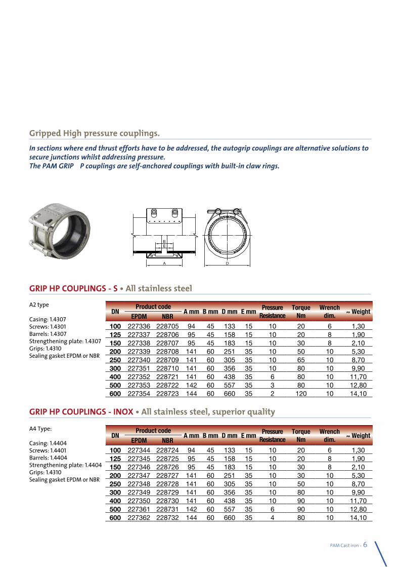
PAM Cast iron - 69
GRIP HP COUPLINGS - S • All stainless steel
DNProduct code
A mm B mm D mm E mmPressure
ResistanceTorque
NmWrench
dim.≈ Weight
EPDM NBR100 227336 228705 94 45 133 15 10 20 6 1,30125 227337 228706 95 45 158 15 10 20 8 1,90150 227338 228707 95 45 183 15 10 30 8 2,10200 227339 228708 141 60 251 35 10 50 10 5,30250 227340 228709 141 60 305 35 10 65 10 8,70300 227351 228710 141 60 356 35 10 80 10 9,90400 227352 228721 141 60 438 35 6 80 10 11,70500 227353 228722 142 60 557 35 3 80 10 12,80600 227354 228723 144 60 660 35 2 120 10 14,10
DNProduct code
A mm B mm D mm E mmPressure
ResistanceTorque
NmWrench
dim.≈ Weight
EPDM NBR100 227344 228724 94 45 133 15 10 20 6 1,30125 227345 228725 95 45 158 15 10 20 8 1,90150 227346 228726 95 45 183 15 10 30 8 2,10200 227347 228727 141 60 251 35 10 30 10 5,30250 227348 228728 141 60 305 35 10 50 10 8,70300 227349 228729 141 60 356 35 10 80 10 9,90400 227350 228730 141 60 438 35 10 90 10 11,70500 227361 228731 142 60 557 35 6 90 10 12,80600 227362 228732 144 60 660 35 4 80 10 14,10
Gripped High pressure couplings.Insectionswhereendthrusteffortshavetobeaddressed,theautogripcouplingsarealternativesolutionstosecurejunctionswhilstaddressingpressure.ThePAMGRIPHPcouplingsareself-anchoredcouplingswithbuilt-inclawrings.
A2 type
Casing: 1.4307Screws: 1.4301Barrels: 1.4307Strengthening plate: 1.4307Grips: 1.4310Sealing gasket EPDM or NBR
A4 Type:
Casing: 1.4404Screws: 1.4401Barrels: 1.4404Strengthening plate: 1.4404Grips: 1.4310Sealing gasket EPDM or NBR
GRIP HP COUPLINGS - INOX • All stainless steel, superior quality
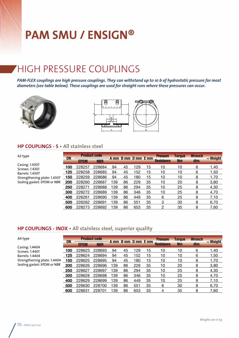
70 - PAM Cast iron
Weights are in kg
PAM SMU / ENSIGN®
HIGH PRESSURE COUPLINGSPAM-FLEXcouplingsarehighpressurecouplings.Theycanwithstandupto10bofhydrostaticpressureformostdiameters(seetablebelow).Thesecouplingsareusedforstraightrunswherethesepressurescanoccur.
HP COUPLINGS - S • All stainless steel
A2 type
Casing: 1.4307Screws: 1.4301Barrels: 1.4307Strengthening plate: 1.4307Sealing gasket: EPDM or NBR
A4 type
Casing: 1.4404Screws: 1.4401Barrels: 1.4404Strengthening plate: 1.4404Sealing gasket: EPDM or NBR
HP COUPLINGS - INOX • All stainless steel, superior quality
DNProduct code
A mm B mm D mm E mmPressure
ResistanceTorque
NmWrench
dim.≈ Weight
EPDM NBR100 228257 228684 94 45 129 15 10 10 6 1,40125 228258 228685 94 45 152 15 10 10 6 1,50150 228259 228686 94 45 180 15 10 10 8 1,70200 228260 228687 139 86 229 35 10 20 8 3,80250 228271 228688 139 86 294 35 10 25 8 4,30300 228272 228689 139 86 346 35 10 25 8 4,70400 226261 228690 139 86 449 35 6 25 8 7,10500 226262 228691 139 86 551 35 3 30 8 6,70600 228273 228692 139 86 653 35 2 35 8 7,60
DNProduct code
A mm B mm D mm E mmPressure
ResistanceTorque
NmWrench
dim.≈ Weight
EPDM NBR100 228623 228693 94 45 129 15 10 10 6 1,40125 228624 228694 94 45 152 15 10 10 6 1,50150 228625 228695 94 45 180 15 10 10 8 1,70200 228626 228696 139 86 229 35 10 20 8 3,80250 228627 228697 139 86 294 35 10 25 8 4,30300 228628 228698 139 86 346 35 10 25 8 4,70400 228629 228699 139 86 449 35 10 25 8 7,10500 228630 228700 139 86 551 35 6 30 8 6,70600 228631 228701 139 86 653 35 4 35 8 7,60
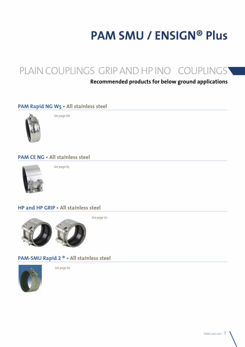
PAM Cast iron - 71
PAM SMU / ENSIGN® Plus
PLAIN COUPLINGS, GRIP AND HP INOX COUPLINGS
PAM Rapid NG W5 • All stainless steel
PAM CE NG • All stainless steel
HP and HP GRIP • All stainless steel
PAM-SMU Rapid 2 ® • All stainless steel
See page 66
See page 65
See page 70
See page 67
Recommended products for below ground applications
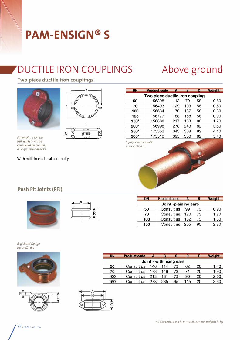
72 - PAM Cast iron
PAM-ENSIGN® S
DUCTILE IRON COUPLINGSTwo piece ductile iron couplings
Push Fit Joints (PFJ)
All dimensions are in mm and nominal weights in kg
DN Product code A B C WeightTwo piece ductile iron coupling
50 156398 113 79 58 0.6070 156493 129 103 58 0.60100 156634 170 137 58 0.80125 156777 188 158 58 0.90150* 156888 217 183 80 1.70200* 156998 278 243 82 3.50250* 175552 343 308 82 4.40300* 175510 395 360 82 5.40
DN Product code A B C D E WeightJoint - with fixing ears
50 Consult us 146 114 73 62 20 1.4070 Consult us 178 146 73 71 20 1.90100 Consult us 213 181 73 90 20 2.60150 Consult us 273 235 95 115 20 3.60
Patent No. 2 305 481 NBR gaskets will be considered on request,on a quotational basis.
Registered Design No. 2 083 167
DN Product code A B WeightJoint -plain no ears
50 Consult us 99 73 0.9070 Consult us 120 73 1.20100 Consult us 152 73 1.80150 Consult us 205 95 2.80
*150-300mm include 4 socket bolts.
With built-in electrical continuity
Above ground
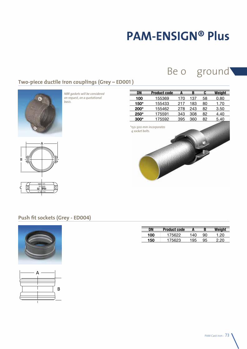
PAM Cast iron - 73
Two-piece ductile iron couplings (Grey – ED001 )
Push fit sockets (Grey - ED004)
PAM-ENSIGN® Plus
DN Product code A B C Weight100 155369 170 137 58 0.80150* 155433 217 183 80 1.70200* 155462 278 243 82 3.50250* 175591 343 308 82 4.40300* 175592 395 360 82 5.40
* 150-300 mm incorporates 4 socket bolts.
NBR gaskets will be considered on request, on a quotational basis.
DN Product code A B Weight100 175622 140 90 1.20150 175623 195 95 2.20
Below ground

74 - PAM Cast iron
PAM SMU / ENSIGN®
CONNECTORSStepping rings for connection to other materials
Adapting collar
Adapting collar and stepping ring
Adapting joint
EPDM plugs: possible branch connection
All dimensions are in mm and nominal weights in kg
DN roduct code DE* Weight Materials50 156399 50 0.02 HDPE and PVC75 156495 63 0.06 HDPE75 156494 77 0.03 PVC100 156555 91 0.10 HDPE100 156635 100 0.05 PVC125 156778 125 0.06 HDPE and PVC200 157000 200 0.15 HDPE and PVC250 157085 250 0.45 HDPE and PVC
DN Product code D mini D maxi L Weight
75 155001 75 90 100 0.40100 155002 100 115 100 0.70100 TXB10NP01 110 121 120 0.70125 TXB12NL0G 130 150 120 1.00150 TXB15NM0J 150 175 120 1.00200 TXB20NL0K 200 225 150 1.50
Use with a PAM-SMU® Rapid 2 or a PAM CV-CE
DN 100
DN 50 DN 75 DN 100
EPDM plugs 1 or 2 inlets
EPDM plug 3 inlets
DN Product code D mini D maxi d mini d maxi L Weight
200 TXB20NN0K 200 225 192 201 150 1.90
DN Product code D mini D maxi d mini d maxi L Weight
150 155003 155 170 130 145 120 0.80200 155004 170 193 210 235 150 1.50
DN Product
code1st aperture
Ø in mm2nd aperture
Ø in mm3rd aperture
Ø in mmWeight
with stainless steel collar50 156394 32 or 40 0,1075 156492 (32 or 40) or (42 or 50) 0,18100 156628 32 or 40 32 0,29
without stainless steel collar100 156629 (32 or 40) or 42 (32 or 40) or (42 or 50) (32 or 40) or (42 or 50) or 54 0,36
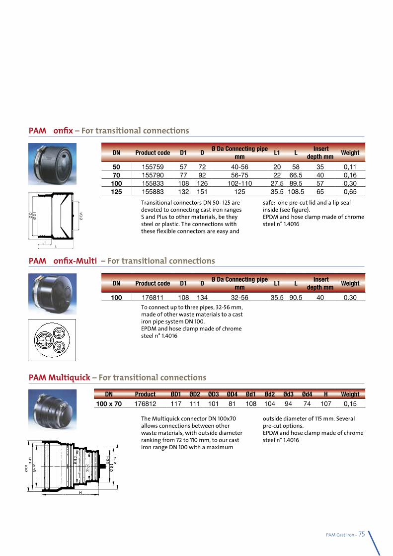
PAM Cast iron - 75
PAM Konfix – For transitional connections
PAM Konfix-Multi – For transitional connections
PAM Multiquick – For transitional connections
The Multiquick connector DN 100x70 allows connections between other waste materials, with outside diameter ranking from 72 to 110 mm, to our cast iron range DN 100 with a maximum
outside diameter of 115 mm. Several pre-cut options.EPDM and hose clamp made of chrome steel n° 1.4016
To connect up to three pipes, 32-56 mm, made of other waste materials to a cast iron pipe system DN 100.EPDM and hose clamp made of chrome steel n° 1.4016
Transitional connectors DN 50- 125 are devoted to connecting cast iron ranges S and Plus to other materials, be they steel or plastic. The connections with these flexible connectors are easy and
safe: one pre-cut lid and a lip seal inside (see figure).EPDM and hose clamp made of chrome steel n° 1.4016
DN Product code D1 DØ Da Connecting pipe
mmL1 L
Insert depth mm
Weight
50 155759 57 72 40-56 20 58 35 0,1170 155790 77 92 56-75 22 66.5 40 0,16100 155833 108 126 102-110 27.5 89.5 57 0,30125 155883 132 151 125 35.5 108.5 65 0,65
DN Product code D1 DØ Da Connecting pipe
mmL1 L
Insert depth mm
Weight
100 176811 108 134 32-56 35.5 90.5 40 0.30
DN Product ØD1 ØD2 ØD3 ØD4 Ød1 Ød2 Ød3 Ød4 H Weight100 x 70 176812 117 111 101 81 108 104 94 74 107 0,15
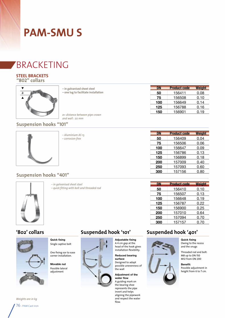
76 - PAM Cast iron
PAM-SMU S
BRACKETING
Weights are in kg
“802” collars
Suspension hooks “101”
Suspension hooks “401”
DN Product code Weight50 156411 0.0875 156508 0.10100 156649 0.14125 156788 0.16150 156901 0.19
DN Product code Weight50 156409 0.0475 156506 0.06100 156647 0.09125 156786 0.13150 156899 0.18200 157009 0.40250 157093 0.60300 157156 0.80
DN Product code Weight50 156410 0.1075 156507 0.13100 156648 0.19125 156787 0.22150 156900 0.25200 157010 0.64250 157094 0.70300 157157 0.70
– in galvanised sheet steel– quick fitting with bolt and threaded rod
– Aluminium AS 13– corrosion-free
a= distance between pipe crownand wall : 20 mm
– in galvanised sheet steel – one lug to facilitate installationa
s
s
STEEL BRACKETS
Quick fixing
Single captive bolt
One fixing ear to ease corner installation.
Movable nut
Possible lateral adjustment
‘802’ collarsAdjustable fixing A 4 cm gap at the head of the hook gives installation flexibility.
Reduced bearing surface Designed to adapt possible unevenness of the wall
Adjustment of the water flow A guiding mark on the bearing shoe represents the pipe invert and helps aligning the pipework and respect the water flow.
Suspended hook ‘101’Quick fixing Owing to the recess and the snugs
Threaded rod and bolt: M8 up to DN 150 M12 from DN 200
Benefit: Possible adjustment in height from 6 to 7 cm.
Suspended hook ‘401’
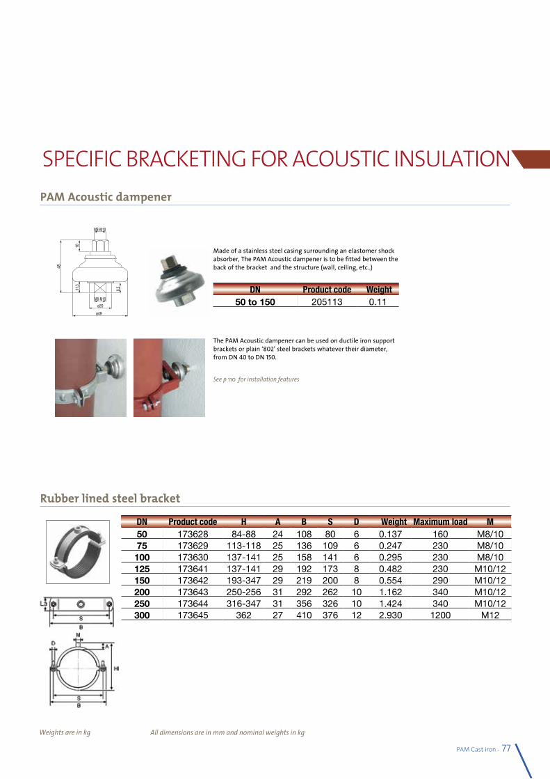
All dimensions are in mm and nominal weights in kg
PAM Cast iron - 77
PAM Acoustic dampener
Rubber lined steel bracket
SPECIFIC BRACKETING FOR ACOUSTIC INSULATION
Weights are in kg
DN Product code H A B S D Weight Maximum load M50 173628 84-88 24 108 80 6 0.137 160 M8/1075 173629 113-118 25 136 109 6 0.247 230 M8/10100 173630 137-141 25 158 141 6 0.295 230 M8/10125 173641 137-141 29 192 173 8 0.482 230 M10/12150 173642 193-347 29 219 200 8 0.554 290 M10/12200 173643 250-256 31 292 262 10 1.162 340 M10/12250 173644 316-347 31 356 326 10 1.424 340 M10/12300 173645 362 27 410 376 12 2.930 1200 M12
Made of a stainless steel casing surrounding an elastomer shock absorber, The PAM Acoustic dampener is to be fitted between the back of the bracket and the structure (wall, ceiling, etc..)
The PAM Acoustic dampener can be used on ductile iron support brackets or plain ‘802’ steel brackets whatever their diameter, from DN 40 to DN 150.
See p 110 for installation features
DN Product code Weight50 to 150 205113 0.11
M8-M10
M8-M10
ø20
ø49
48
1011
,3
8,5
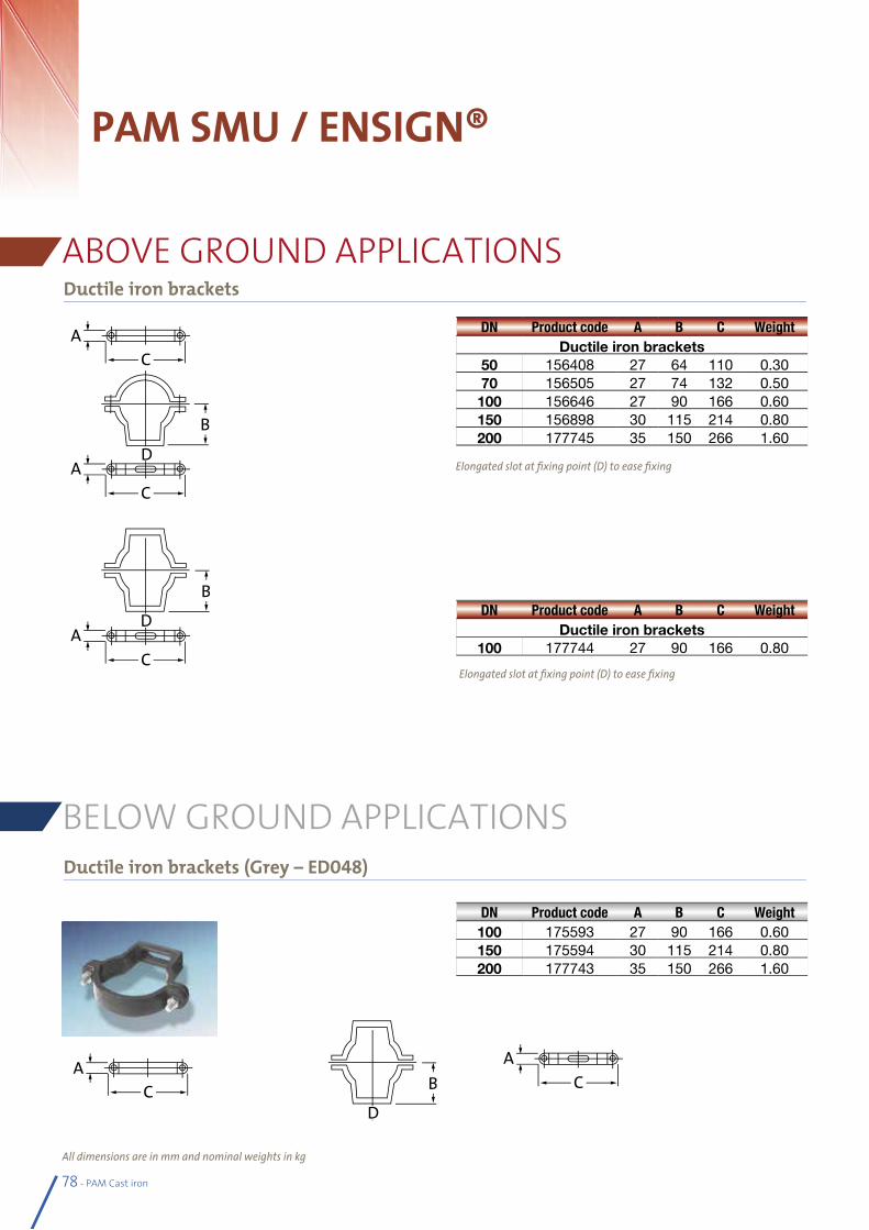
78 - PAM Cast iron
PAM SMU / ENSIGN®
ABOVE GROUND APPLICATIONSDuctile iron brackets
All dimensions are in mm and nominal weights in kg
DN Product code A B C WeightDuctile iron brackets
50 156408 27 64 110 0.3070 156505 27 74 132 0.50100 156646 27 90 166 0.60150 156898 30 115 214 0.80200 177745 35 150 266 1.60
DN Product code A B C WeightDuctile iron brackets
100 177744 27 90 166 0.80
Elongated slot at fixing point (D) to ease fixing
Elongated slot at fixing point (D) to ease fixing
Ductile iron brackets (Grey – ED048)
BELOW GROUND APPLICATIONS
DN Product code A B C Weight100 175593 27 90 166 0.60150 175594 30 115 214 0.80200 177743 35 150 266 1.60
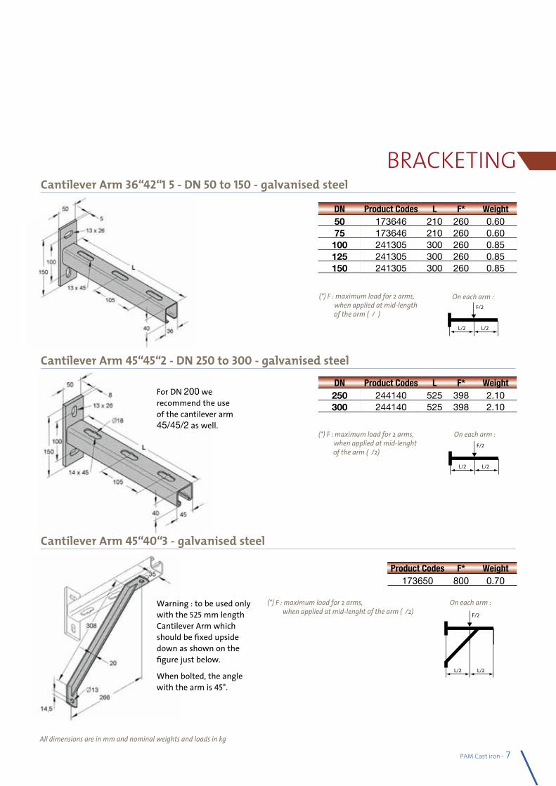
PAM Cast iron - 79
Cantilever Arm 36/42/1,5 - DN 50 to 150 - galvanised steel
Cantilever Arm 45/45/2 - DN 250 to 300 - galvanised steel
BRACKETING
All dimensions are in mm and nominal weights and loads in kg
F/2
L/2 L/2
F/2
L/2 L/2
On each arm :(*) F : maximum load for 2 arms, when applied at mid-length
of the arm (L/2)
F/2
L/2 L/2
F/2
L/2 L/2
On each arm :(*) F : maximum load for 2 arms, when applied at mid-lenght
of the arm (L/2)
F/2
L/2 L/2
F/2
L/2 L/2
On each arm :(*) F : maximum load for 2 arms, when applied at mid-lenght of the arm (L/2)
Warning : to be used only with the 525 mm length Cantilever Arm which should be fixed upside down as shown on the figure just below.
When bolted, the angle with the arm is 45°.
For DN 200 we recommend the use of the cantilever arm 45/45/2 as well.
Cantilever Arm 45/40/3 - galvanised steel
DN Product Codes L F* Weight50 173646 210 260 0.6075 173646 210 260 0.60100 241305 300 260 0.85125 241305 300 260 0.85150 241305 300 260 0.85
DN Product Codes L F* Weight250 244140 525 398 2.10300 244140 525 398 2.10
Product Codes F* Weight173650 800 0.70
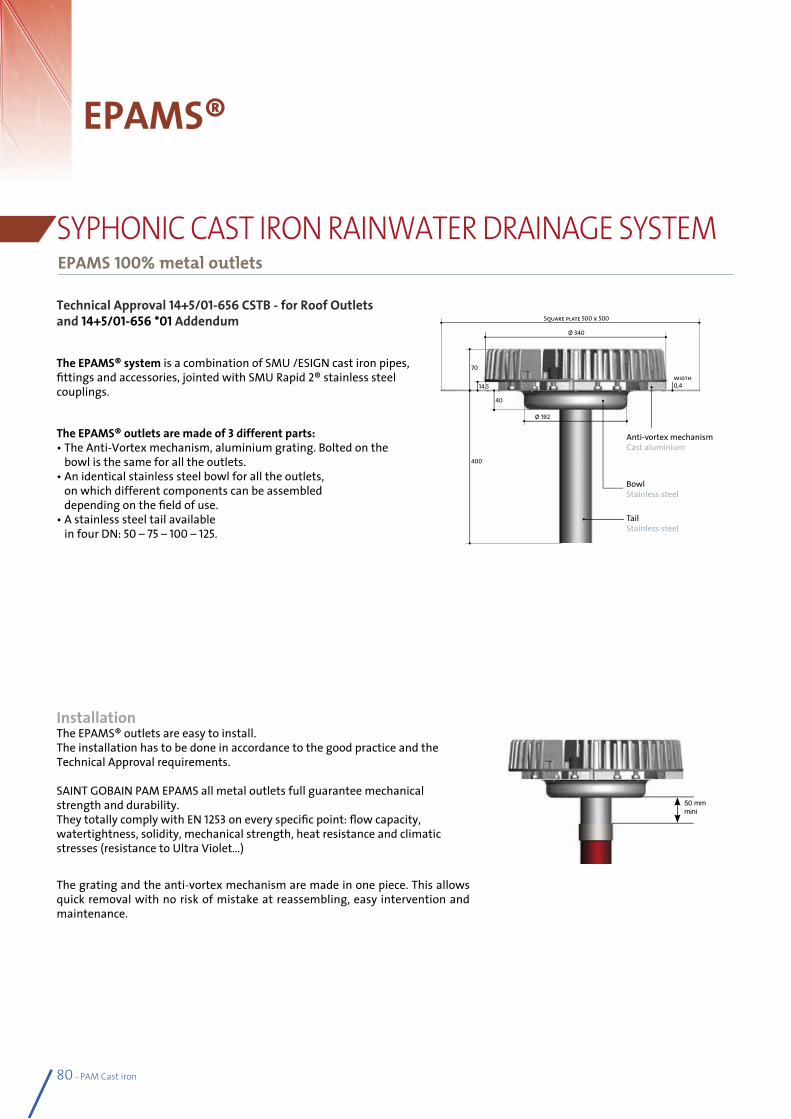
80 - PAM Cast iron
EPAMS®
EPAMS 100% metal outlets
SYPHONIC CAST IRON RAINWATER DRAINAGE SYSTEM
Technical Approval 14+5/01-656 CSTB - for Roof Outletsand 14+5/01-656 *01 Addendum
The EPAMS® system is a combination of SMU /ESIGN cast iron pipes, fittings and accessories, jointed with SMU Rapid 2® stainless steel couplings.
The EPAMS® outlets are made of 3 different parts:• The Anti-Vortex mechanism, aluminium grating. Bolted on the
bowl is the same for all the outlets.• An identical stainless steel bowl for all the outlets,
on which different components can be assembled depending on the field of use.
• A stainless steel tail available in four DN: 50 – 75 – 100 – 125.
Installation The EPAMS® outlets are easy to install. The installation has to be done in accordance to the good practice and the Technical Approval requirements.
SAINT GOBAIN PAM EPAMS all metal outlets full guarantee mechanical strength and durability. They totally comply with EN 1253 on every specific point: flow capacity, watertightness, solidity, mechanical strength, heat resistance and climatic stresses (resistance to Ultra Violet…)
The grating and the anti-vortex mechanism are made in one piece. This allows quick removal with no risk of mistake at reassembling, easy intervention and maintenance.
Anti-vortex mechanismCast aluminium
BowlStainless steel
TailStainless steel
40
400
14,5
70width 0,4
Ø 192
Ø 340
Square plate 500 x 500
50 mm mini
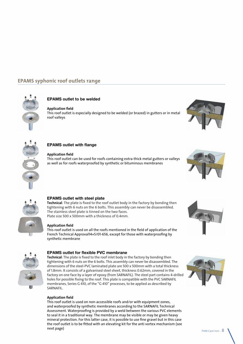
PAM Cast iron - 81
EPAMS syphonic roof outlets range
EPAMS outlet to be welded
Application field:This roof outlet is especially designed to be welded (or brazed) in gutters or in metal roof valleys
EPAMS outlet with flange
Application field:This roof outlet can be used for roofs containing extra-thick metal gutters or valleys as well as for roofs waterproofed by synthetic or bituminous membranes
EPAMS outlet with steel plateTechnical: The plate is fixed to the roof outlet body in the factory by bonding then tightening with 6 nuts on the 6 bolts. This assembly can never be disassembled. The stainless steel plate is tinned on the two faces.Plate size 500 x 500mm with a thickness of 0.4mm.
Application field:This roof outlet is used on all the roofs mentioned in the field of application of the French Technical Approval14+5/01-656, except for those with waterproofing by synthetic membrane
EPAMS outlet for flexible PVC membraneTechnical: The plate is fixed to the roof inlet body in the factory by bonding then tightening with 6 nuts on the 6 bolts. This assembly can never be disassembled. The dimensions of the steel-PVC laminated plate are 500 x 500mm with a total thickness of 1.8mm. It consists of a galvanised steel sheet, thickness 0.62mm, covered in the factory on one face by a layer of epoxy (from SARNAFIL). The steel part contains 4-drilled holes for possible fixing to the roof. This plate is compatible with the PVC SARNAFIL membranes, Series G 410, of the “G 410” processes, to be applied as described by SARNAFIL.
Application field:This roof outlet is used on non-accessible roofs and/or with equipment zones, and waterproofed by synthetic membranes according to the SARNAFIL Technical Assessment. Waterproofing is provided by a weld between the various PVC elements to seal it in a traditional way. The membrane may be visible or may be given heavy mineral protection. For this latter case, it is possible to use fine gravel but in this case the roof outlet is to be fitted with an elevating kit for the anti vortex mechanism (see next page)
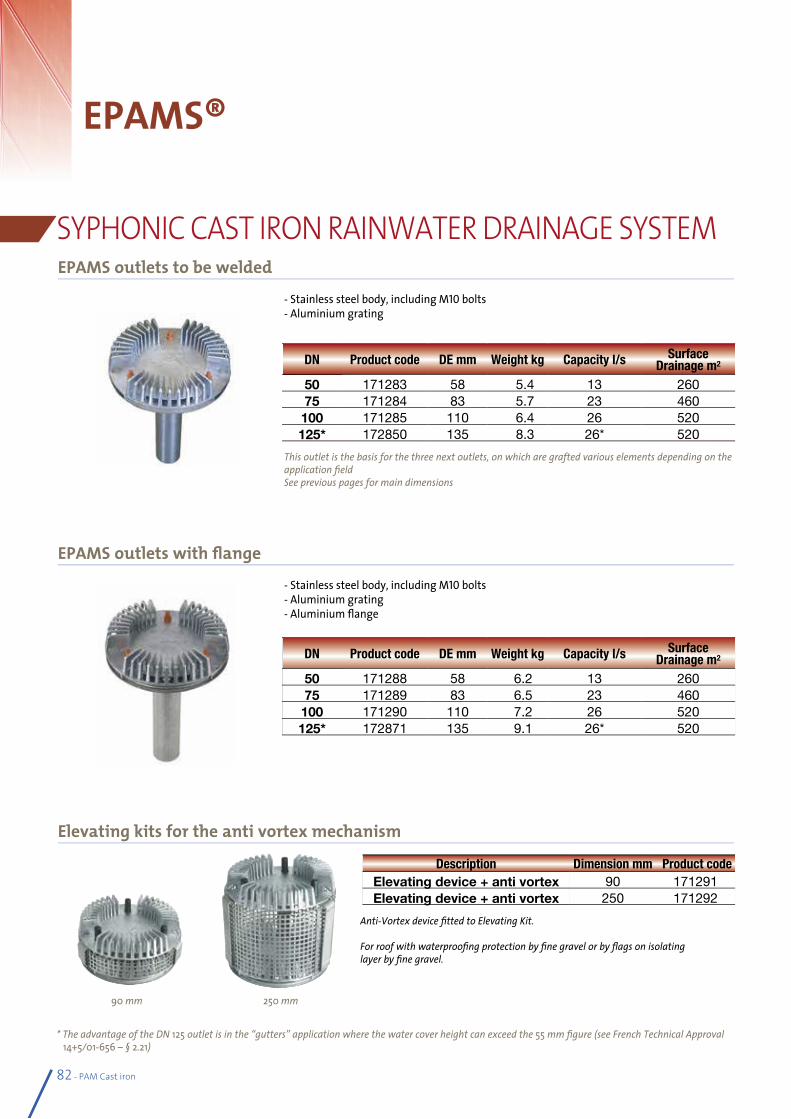
82 - PAM Cast iron
EPAMS®
SYPHONIC CAST IRON RAINWATER DRAINAGE SYSTEMEPAMS outlets to be welded
* The advantage of the DN 125 outlet is in the “gutters” application where the water cover height can exceed the 55 mm figure (see French Technical Approval 14+5/01-656 – § 2.21)
- Stainless steel body, including M10 bolts- Aluminium grating
This outlet is the basis for the three next outlets, on which are grafted various elements depending on the application fieldSee previous pages for main dimensions
DN Product code DE mm Weight kg Capacity l/s Surface Drainage m2
50 171283 58 5.4 13 26075 171284 83 5.7 23 460100 171285 110 6.4 26 520125* 172850 135 8.3 26* 520
DN Product code DE mm Weight kg Capacity l/s Surface Drainage m2
50 171288 58 6.2 13 26075 171289 83 6.5 23 460100 171290 110 7.2 26 520125* 172871 135 9.1 26* 520
EPAMS outlets with flange
Elevating kits for the anti vortex mechanism
- Stainless steel body, including M10 bolts- Aluminium grating- Aluminium flange
90 mm 250 mm
Description Dimension mm Product code Elevating device + anti vortex 90 171291Elevating device + anti vortex 250 171292
Anti-Vortex device fitted to Elevating Kit.
For roof with waterproofing protection by fine gravel or by flags on isolatinglayer by fine gravel.
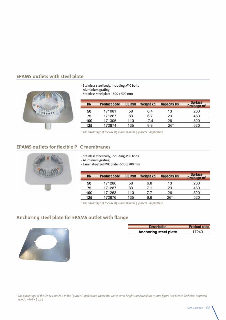
PAM Cast iron - 83
* The advantage of the DN 125 outlet is in the “gutters” application where the water cover height can exceed the 55 mm figure (see French Technical Approval 14+5/01-656 – § 2.21)
EPAMS outlets with steel plate
- Stainless steel body, including M10 bolts- Aluminium grating- Stainless steel plate - 500 x 500 mm
* The advantage of the DN 125 outlet is in the « gutters » application
DN Product code DE mm Weight kg Capacity l/s Surface Drainage m2
50 171081 58 6.4 13 26075 171267 83 6.7 23 460100 171305 110 7.4 26 520125 172874 135 9.3 26* 520
DN Product code DE mm Weight kg Capacity l/s Surface Drainage m2
50 171286 58 6.8 13 26075 171287 83 7.1 23 460100 171263 110 7.7 26 520125 172876 135 9.6 26* 520
EPAMS outlets for flexible PVC membranes
- Stainless steel body, including M10 bolts- Aluminium grating- Laminate-steel PVC plate - 500 x 500 mm
* The advantage of the DN 125 outlet is in the « gutters » application
Description Product code Anchoring steel plate 172431
Anchoring steel plate for EPAMS outlet with flange
General conditions of salesArticle 1 - GENERAL PROVISIONSThese general conditions of sale determine the rights and obligations of Saint-Gobain PAM (“SG PAM”) and of the Client.All orders by the Client shall entail the Client’s acceptance of these general conditions of sale. The Client’s general conditions of purchase cannot prevail over these general conditions of sale unless SG PAM agrees thereto.
Article 2 - ORDERS - ACCEPTANCE2.1 Each order for products issued by the Client must be identified as being an order and must contain accurate and sufficient information
concerning, for example, labelling and delivery, in order to allow SG PAM to process the order under the best possible conditions. If the information is insufficient or inaccurate, SG PAM may, without prejudice to any other solution, delay the product dispatch date.
2.2 Orders shall only become firm and definitive following the issue of an order acknowledgement by SG PAM. No order changes or cancellations can be taken into account after the order acknowledgment has been issued.
Article 3 - PRICES3.1 The prices invoiced shall be those prices that result from the price lists in force on the effective date of delivery or, if there is an offer,
the prices contained in said offer, to the extent that the order reaches SG PAM during the period of validity of said offer.3.2 When SG PAM issues an offer, the prices shall be firm for the duration of the offer or for a maximum of 3 months following the issue
date of said offer. Thereafter, price increases may be applied.3.3 Except as otherwise agreed, the prices are expressed in euros and net of all taxes. The prices shall be invoiced after application of value
added tax at the rate in force.
Article 4 - DELIVERY4.1 The delivery times are minimum times and provided for information only. A delivery time is only firm if expressly described as such in
the order acknowledgment.4.2 Failure to comply with the indications concerning the delivery time does not authorise the Client to cancel its order, to defer payment
for the order compared to the agreed conditions or to perform any form of withholding or offsetting whatsoever.4.3 No default penalties may be claimed by from SG PAM unless the principle, terms and conditions of such penalties have been expressly
accepted in the order acknowledgement.4.4 SG PAM is not liable for failure to comply with delivery times when: • the Client did not comply with the payment conditions; or
• when the information to be provided by the Client did not arrive in time;4.5 The title to the products shall be transferred to the Client on SG PAM’s premises as soon as the products can be identified individually
and collected by the carrier.4.6 The risks shall be transferred under the conditions defined by the chosen Incoterm (Incoterms published by the Paris International
Chamber of Commerce in force on the effective date of delivery, the “Incoterms”) or when the products are identified individually and collected by the carrier.
4.7 The terms “carriage paid“ or “flat-rate carriage” correspond to the Incoterm CPT.
Article 5 - INSPECTION 5.1 The products shall be inspected in the factory, in accordance with SG PAM’s quality control procedures and the standards in force. 5.2 When it is agreed that a special inspection will be performed, by the Client or by an organisation that represents the Client, the
inspectors who are responsible for performing the inspection shall be informed of the dates and times at which inspection operations must normally take place.
Article 6 - TRANSPORT6.1 When the Client organises the transport operations itself, the Client shall be responsible for fulfilling the obligations to adapt the
vehicles to the products and the obligation to schedule loading 48 hours in advance. If not, loading will not be possible.6.2 The Client shall be responsible for the unloading operations, which shall be performed under its supervision. In this respect, the Client
must ensure compliance with the on-site safety conditions and make available suitable means in order to ensure the unloading takes place under the best possible safety conditions. In particular, in the event of delivery by crane truck, the Client shall assist the driver by unhooking the pipes and packages at ground level. The Client must draw up a safety protocol with the carrier prior to the unloading operations.
6.3 In the event of losses, damage or missing goods recorded at the time of delivery, the Client shall exercise its right of recourse against the carrier by mentioning reserves on the carrier‘s delivery note. The Client shall confirm said reserves and substantiate its claim to the carrier, by registered letter with return receipt, within 3 business days following the receipt of the products.
Article 7 - PAYMENT TERMS7.1 Payments shall be made to the address shown on the invoice, within 30 days end of month as from the invoice date of issue, regardless
of the date of receipt of the products by the Client.7.2 Accepted bills of exchange must be returned within 10 days of issue. This timeframe shall also apply to the orders to pay issued by the
Client.7.3 All payments made after the payment deadline shown on the invoice shall, by rights, trigger the invoicing of default penalties at a rate
equal to three times the legal rate of interest in force.7.4 If an invoice is not paid when due, all invoices that have fallen due shall immediately become payable. Moreover, SG PAM reserves the
right to suspend the orders in process, without prejudice to damages.7.5 No Client claims can lead to a change, delay or suspension of payments that have fallen due or authorise the Client to perform any
offsetting or deduction whatsoever with the monies that are owed to SG PAM. All offsetting or deductions not agreed on beforehand shall constitute a payment incident that justifies the application of the measures referred to above.
7.6 In the event of a major change in the Client’s legal or financial status, which has an impact on SG PAM’s assessment of the Client’s solvency or in the event of excessive amounts outstanding, SG PAM reserves the right, even after partially filling an order, either to demand guarantees or to cancel the remainder of the orders.
Article 8 - PRODUCT WARRANTY8.1 Without prejudice to the measures to be implemented vis-à-vis the carrier, claims regarding the non-conformity of the products
delivered with the products shown on the order acknowledgment of receipt must be made in writing within 3 days of the receipt of the products. Thereafter, no claims shall be accepted.
84 - PAM Cast iron
PAM Cast iron - 85
8.2 SG PAM warrants the Client against the latent defects that may affect the sold products. If the Client notes a manufacturing defect in the product, which, in the Client’s opinion, is characteristic of a latent defect, the Client must make a claim to SG PAM without delay.
8.3 Triggering the conformity warranty and the latent defects warranty is contingent on the existence of said defects being confirmed in the presence of both parties and acknowledged as being effectively attributable to SG PAM. The Client shall provide all proof of the reality of the conformity or latent defects observed. The Client must give SG PAM every opportunity to observe said conformity or latent defects and to correct them. The Client shall refrain from intervening on the products.
8.4 Within 1 month – all things remaining as is, except in the event of force majeure –the conformity or latent defect shall be recorded in an official document, in the presence of SG PAM’s representatives.
8.5 If the existence of a conformity or latent defect is recorded in the presence of both parties and acknowledged by SG PAM as being effectively attributable to it, SG PAM shall take responsibility for repairing the product or supplying a product to replace the product previously delivered and shall pay the corresponding transport costs.
8.6 The Client is required, under its exclusive liability, to comply with the instructions given by SG PAM as well as with best practices for the handling and appropriate use of the products, as well as all the technical guidelines.
8.7 The guarantee provided shall not apply in the following cases: • apparent defect or a defect that a professional should have discovered; • defects and/or deteriorations caused by natural wear and tear or an external accident; • modification of the product that is not provided for or specified by SG PAM; • defects and/or deteriorations caused by a lack of compatibility with products not supplied by SG PAM; • failure by the Client to comply with the indications concerning the handling, the installation, the use and the maintenance of the products, as well as with
best practices; • force majeure or an assimilated event.8.8 The warranty granted by SG PAM shall last for 12 months as from delivery. Work carried out under the warranty shall not extend the warranty period.
Article 9 - LIABILITYUnder no circumstances may SG PAM be held liable for the indirect material damages and for the direct and/or indirect consequential damages (such as operating loss or loss of clientele, compensation for delay, etc.), that are alleged by the Client, which may result from a failure to comply with SG PAM’s obligations, in particular in the event of non-conformity or of a defect that affects its products.
Article 10 - INDUSTRIAL PROPERTYThe plans, models, studies, results of tests, catalogues, manuals, and all the marketing and technical documents circulated by SG PAM, regardless of the media used, are the exclusive property of SG PAM. Consequently, the Client shall refrain from making any reproduction thereof whatsoever without SG PAM’s prior agreement.
Article 11 - MANUFACTURING - RECOMMENDATIONS11.1 The weights and dimensions of the products stated on SG PAM’s documents are theoretical values. SG PAM reserves the right to make all amendments to the
information contained in its documentation.11.2 The documents concerning the handling, storage, installation, use and maintenance of the products are supplied free of charge by SG PAM, at the Client’s
request. The Client alone shall be liable for compliance with the health and safety conditions for these various operations and for the use of the products in accordance with best practices.
11.3 SG PAM reserves the right to amend the data contained in these documents at any time. It is the Client’s responsibility to verify the validity thereof with SG PAM.
Article 12 - CONDITIONING 12.1 The product packaging is designed in order to meet haulage requirements.12.2 The packaging and bracing wood not invoiced by SG PAM shall be recovered at the time of delivery.
Article 13 - FORCE MAJEURE13.1 SG PAM shall not be liable in the event of force majeure. Force majeure shall be understood to mean all causes that are beyond SG PAM’s control, which would
make it impossible to fulfil its contractual obligations and would affect the manufacturing, dispatch and delivery of the products. The following, inter alia, are deemed to be cases of force majeure: disturbances to production and/or delivery that result from war (declared or undeclared), strikes, lockouts, accidents, fires, floods, natural disasters, epidemics, interruptions or delays in haulage, shortages of materials and/or raw materials, embargos or regulations of any kind whatsoever.
13.2 In the event of force majeure, SG PAM shall have a reasonable supplemental timeframe in which to perform its obligations.
Article 14 - APPLICABLE LAW - JURISDICTIONIn the event of a contestation concerning the formation, performance or construction of the sale contract, solely the Nancy courts shall have jurisdiction, even in the event of multiple respondents, third party notices or emergency interim proceedings. French law shall be the applicable law.
Logistic characterisation
Obsolete pa ttern: the pattern is no longer active. Should these components be ordered again, the quotation would include the re- activation of the tools.
On a quotational basis: these components are made to order. To secure delivery time, the related orders should be anticipated. Depending on the quantity ordered, a special logistic surcharge could also be applied.
86 - PAM Cast iron
PAM Cast iron - 87
Specifier’s Manual
Sect
ion 3
SAINT-GOBAIN CAST IRON PIPE SYSTEMS1ST CHOICE FOR PROJECT MANAGERS AND PROFESSIONAL INSTALLERS
l Project support - assistance from our Technical Departments and commitment of our sales teams, to advise and help you to make the right choice.
l Traditional and precise mechanical assembly – with simple tools, without gluing or welding, to overcome on site difficulties.
l Simple to install, cast iron systems do not require specially trained installers to complete the installations.
l Dependable installation– SMU-Ensign ranges minimise the risk of error and help reach the expected performances immediately .
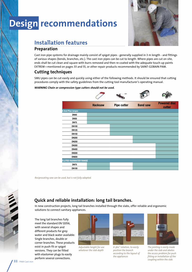
In new construction projects, long tail branches installed through the slabs, offer reliable and ergonomic solutions to connect sanitary appliances.
The long tail branches fully meet the standard EN 12056, with several shapes and different products for grey water and black water available: Single branches, double or corner branches. These products exist in push-fit or spigot versions. They can be fitted with elastomer plugs to easily perform several connections.
88 - PAM Cast iron
Installation featuresPreparation Cast iron pipe systems for drainage mainly consist of spigot pipes - generally supplied in 3 m length - and fittings of various shapes (bends, branches, etc.). The cast iron pipes can be cut to length. Where pipes are cut on site, ends shall be cut clean and square with burrs removed and then re-coated with the adequate touch-up paints EXTREM 1 mentioned on pages 33 and 55, or other repair products recommended by SAINT-GOBAIN PAM.
Cutting techniquesSMU pipes can be cut easily and quickly using either of the following methods. It should be ensured that cutting procedures comply with the safety guidelines from the cutting tool manufacturer’s operating manual.
WARNING Chain or compression type cutters should not be used.
Quick and reliable installation: long tail branches.
Design recommendations
Adjustable height for use whatever the slab depth
A 360° rotation, to easily position the branch according to the layout of the appliances
The jointing is easily made under the slab and abates the access problem for push fitting or installation of the coupling within the slab.
Hacksaw Pipe cutter Band sawPowered disc
cutterS And Plus ranges
DN40
DN50
DN75
DN100
DN125
DN150
DN200
DN250
DN300
DN400
DN500
DN600
FLUTED RAINWATER RANGE
DN75
DN100
Reciprocating saw can be used, but is not fully adapted.
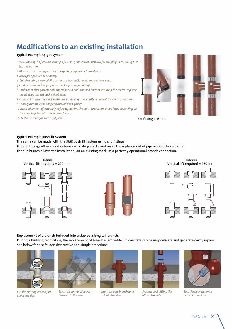
PAM Cast iron - 89
Modifications to an existing installation.Typical example spigot system
1. Measure length of branch, adding a further 15mm in total to allow for coupling’s central register top and bottom.
2. Make sure existing pipework is adequately supported from above. 3. Mark pipe position for cutting. 4. Cut pipe using powered disc cutter or wheel cutter and remove sharp edges. 5. Coat cut ends with appropriate touch-up (epoxy coating). 6. Push the rubber gaskets onto the spigot cut ends top and bottom, ensuring the central registers
are abutted against each spigot edge. 7. Position fitting in the stack within each rubber gasket abutting against the central registers. 8. Loosely assemble the coupling around each gasket. 9. Check alignment of assembly before tightening the bolts, to recommended level, depending on
the couplings technical recommendations. 10. Test new stack for successful joints.
Typical example push-fit systemThe same can be made with the SME push fit system using slip fittings.The slip fittings allow modifications on existing stacks and make the replacement of pipework sections easier. The slip branch allows the installation, on an existing stack, of a perfectly operational branch connection.
X = fitting + 15mm
Replacement of a branch included into a slab by a long tail branch. During a building renovation, the replacement of branches embedded in concrete can be very delicate and generate costly repairs. See below for a safe, non destructive and simple procedure:
Cut the existing branch just above the slab
Seal the openings with cement or sealant.
Proceed push fitting the other elements
Insert the new branch long tail into the slab
Break the former pipe parts included in the slab
*
Slip fittingVertical lift required = 220 mm
*
Slip branchVertical lift required = 280 mm
x
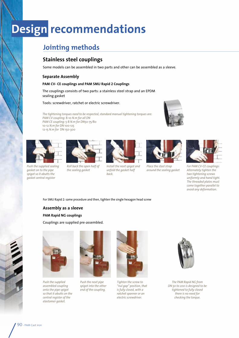
Stainless steel couplingsSome models can be assembled in two parts and other can be assembled as a sleeve.
Separate AssemblyPAM CV- CE couplings and PAM SMU Rapid 2 Couplings
The couplings consists of two parts: a stainless steel strap and an EPDM sealing gasket
Tools: screwdriver, ratchet or electric screwdriver.
The tightening torques need to be respected, standard manual tightening torques are:PAM CV coupling: 8-10 N.m for all DN PAM CE coupling: 5-8 N.m for DN50-75/80 10-12 N.m for DN 100-125 12-15 N.m for DN 150-300
Design recommendations
For SMU Rapid 2: same procedure and then, tighten the single hexagon head screw
Assembly as a sleevePAM Rapid NG couplings
Couplings are supplied pre-assembled.
Push the supplied sealing gasket on to the pipe spigot so it abutts the gasket central register
Roll back the open half of the sealing gasket
Install the next spigot and unfold the gasket half back.
Push the supplied assembled coupling onto the pipe spigotso that it abutts on the central register of theelastomer gasket.
Push the next pipe spigot into the other end of the coupling.
Tighten the screw to“nul gap” position, that is fully closed, with a ratchet spanner or anelectric screwdriver.
Place the steel strap around the sealing gasket
For PAM CV-CE couplings: Alternately tighten the two tightening screws uniformly and hand tight. The threaded plates must come together parallel to avoid any deformation.
The PAM Rapid NG from DN 50 to 200 is designed to be
tightened to fully closedthere is no need for
checking the torque.
90 - PAM Cast iron
Jointing methods
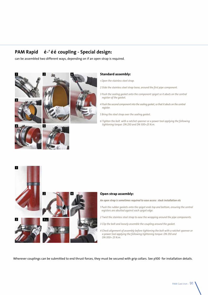
PAM Cast iron - 91
Jointing methods
3 bis
PAM Rapid 250-300 coupling - Special design: can be assembled two different ways, depending on if an open strap is required.
Standard assembly:
1 Open the stainless steel strap. 2 Slide the stainless steel strap loose, around the first pipe component. 3 Push the sealing gasket onto the component spigot so it abuts on the central
register of the gasket. 4 Push the second component into the sealing gasket, so that it abuts on the central
register.
5 Bring the steel strap over the sealing gasket.
6 Tighten the bolt with a ratchet spanner or a power tool applying the following tightening torque: DN 250 and DN 300=25 N.m.
Open strap assembly:
An open strap is sometimes required to ease access: stack installation etc…
1 Push the rubber gaskets onto the spigot ends top and bottom, ensuring the central registers are abutted against each spigot edge.
2 Twist the stainless steel strap to ease the wrapping around the pipe components.
3 Clip the bolt and loosely assemble the coupling around the gasket.
4 Check alignment of assembly before tightening the bolt with a ratchet spanner or a power tool applying the following tightening torque: DN 250 and DN 300= 25 N.m.
1 2
3
4 5
6
1
2
3
4
Wherever couplings can be submitted to end thrust forces, they must be secured with grip collars. See p100 for installation details.
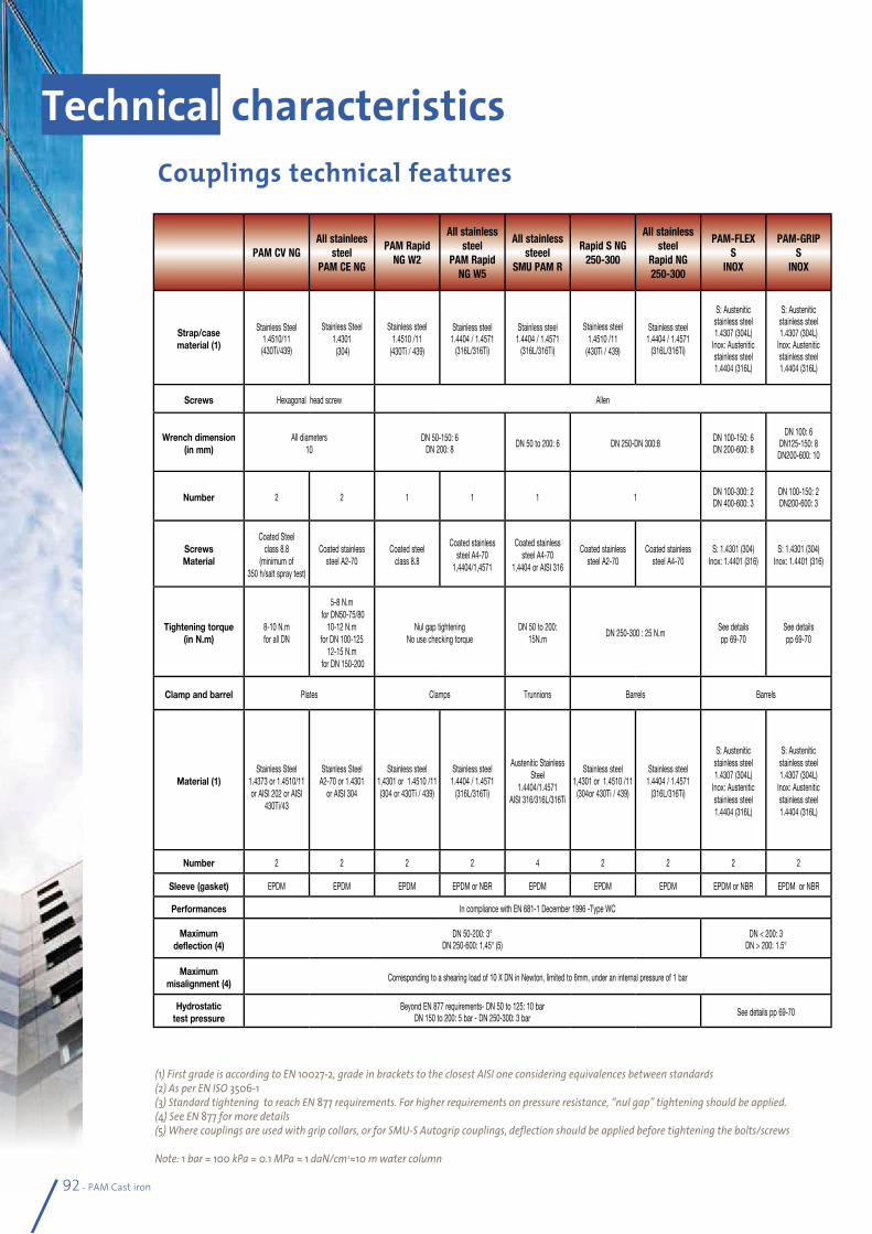
92 - PAM Cast iron
(1) First grade is according to EN 10027-2, grade in brackets to the closest AISI one considering equivalences between standards(2) As per EN ISO 3506-1(3) Standard tightening to reach EN 877 requirements. For higher requirements on pressure resistance, “nul gap” tightening should be applied.(4) See EN 877 for more details(5) Where couplings are used with grip collars, or for SMU-S Autogrip couplings, deflection should be applied before tightening the bolts/screws
Note: 1 bar = 100 kPa = 0.1 MPa ≈ 1 daN/cm2≈10 m water column
Technical characteristics Couplings technical features
PAM CV NGAll stainlees
steel PAM CE NG
PAM Rapid NG W2
All stainless steel
PAM Rapid NG W5
All stainless steeel
SMU PAM R
Rapid S NG 250-300
All stainless steel
Rapid NG 250-300
PAM-FLEX S
INOX
PAM-GRIP S
INOX
Strap/case material (1)
Stainless Steel 1.4510/11 (430Ti/439)
Stainless Steel1.4301 (304)
Stainless steel1.4510 /11
(430Ti / 439)
Stainless steel 1.4404 / 1.4571
(316L/316Ti)
Stainless steel1.4404 / 1.4571
(316L/316Ti)
Stainless steel1.4510 /11
(430Ti / 439)
Stainless steel 1.4404 / 1.4571
(316L/316Ti)
S: Austeniticstainless steel1.4307 (304L)
Inox: Austeniticstainless steel1.4404 (316L)
S: Austeniticstainless steel1.4307 (304L)
Inox: Austeniticstainless steel1.4404 (316L)
Screws Hexagonal head screw Allen
Wrench dimension (in mm)
All diameters 10
DN 50-150: 6DN 200: 8 DN 50 to 200: 6 DN 250-DN 300:8 DN 100-150: 6
DN 200-600: 8
DN 100: 6 DN125-150: 8
DN200-600: 10
Number 2 2 1 1 1 1 DN 100-300: 2 DN 400-600: 3
DN 100-150: 2 DN200-600: 3
Screws Material
Coated Steel class 8.8
(minimum of 350 h/salt spray test)
Coated stainless steel A2-70
Coated steel class 8.8
Coated stainless steel A4-70
1,4404/1,4571
Coated stainless steel A4-70
1,4404 or AISI 316
Coated stainless steel A2-70
Coated stainless steel A4-70
S: 1.4301 (304) Inox: 1.4401 (316)
S: 1.4301 (304) Inox: 1.4401 (316)
Tightening torque (in N.m)
8-10 N.m for all DN
5-8 N.m for DN50-75/80
10-12 N.m for DN 100-125
12-15 N.m for DN 150-200
Nul gap tightening No use checking torque
DN 50 to 200: 15N.m
DN 250-300 : 25 N.mSee details pp 69-70
See details pp 69-70
Clamp and barrel Plates Clamps Trunnions Barrels Barrels
Material (1)
Stainless Steel
1.4373 or 1.4510/11 or AISI 202 or AISI
430Ti/43
Stainless Steel A2-70 or 1.4301
or AISI 304
Stainless steel 1,4301 or 1.4510 /11 (304 or 430Ti / 439)
Stainless steel 1.4404 / 1.4571
(316L/316Ti)
Austenitic Stainless Steel
1.4404/1.4571AISI 316/316L/316Ti
Stainless steel 1,4301 or 1.4510 /11
(304or 430Ti / 439)
Stainless steel 1.4404 / 1.4571
(316L/316Ti)
S: Austenitic stainless steel 1.4307 (304L)
Inox: Austenitic stainless steel 1.4404 (316L)
S: Austenitic stainless steel 1.4307 (304L)
Inox: Austenitic stainless steel 1.4404 (316L)
Number 2 2 2 2 4 2 2 2 2
Sleeve (gasket) EPDM EPDM EPDM EPDM or NBR EPDM EPDM EPDM EPDM or NBR EPDM or NBR
Performances In compliance with EN 681-1 December 1996 -Type WC
Maximum deflection (4)
DN 50-200: 3° DN 250-600: 1,45° (5)
DN < 200: 3DN > 200: 1.5°
Maximum misalignment (4)
Corresponding to a shearing load of 10 X DN in Newton, limited to 6mm, under an internal pressure of 1 bar
Hydrostatic test pressure
Beyond EN 877 requirements- DN 50 to 125: 10 barDN 150 to 200: 5 bar - DN 250-300: 3 bar See details pp 69-70
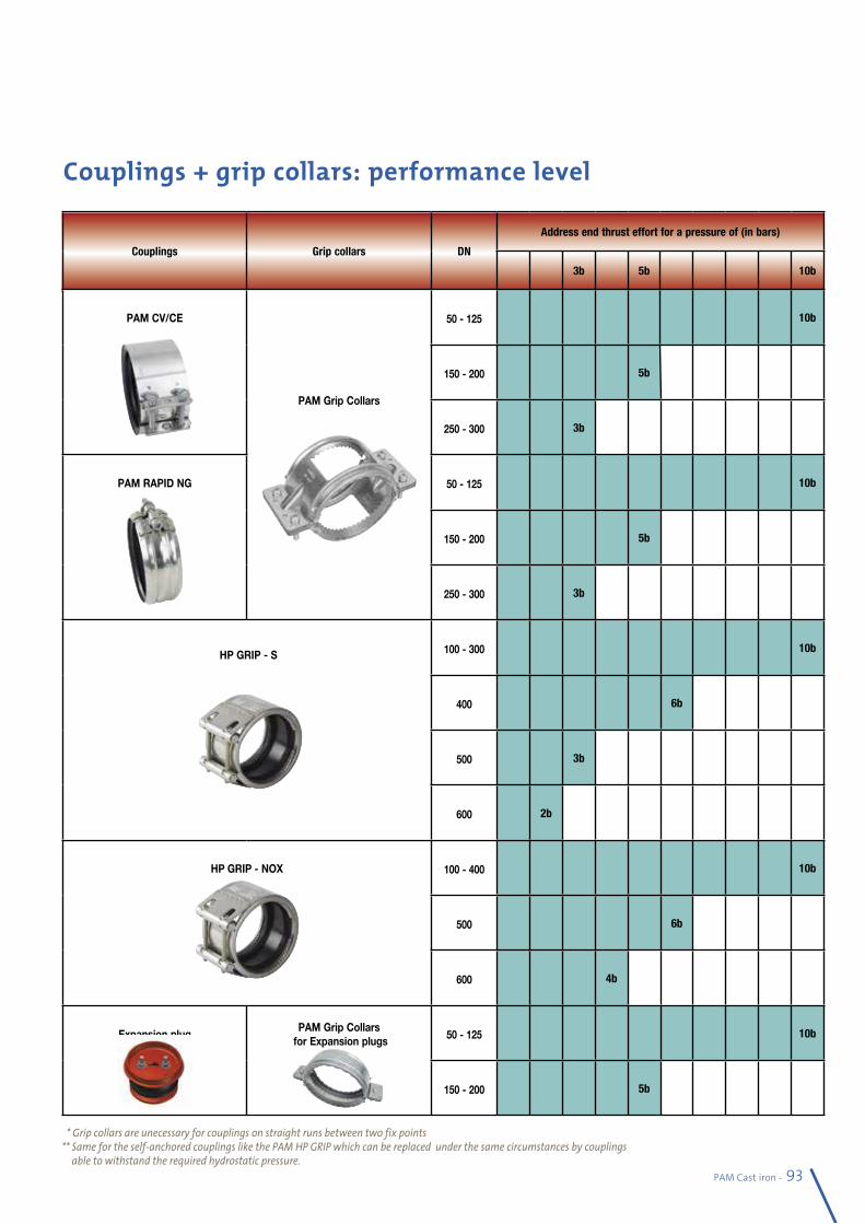
Couplings + grip collars: performance level
PAM Cast iron - 93
* Grip collars are unecessary for couplings on straight runs between two fix points ** Same for the self-anchored couplings like the PAM HP GRIP which can be replaced under the same circumstances by couplings
able to withstand the required hydrostatic pressure.
Couplings Grip collars DN
Address end thrust effort for a pressure of (in bars)
3b 5b 10b
PAM CV/CE
PAM Grip Collars
50 - 125 10b
150 - 200 5b
250 - 300 3b
PAM RAPID NG 50 - 125 10b
150 - 200 5b
250 - 300 3b
HP GRIP - S 100 - 300 10b
400 6b
500 3b
600 2b
HP GRIP - NOX 100 - 400 10b
500 6b
600 4b
Expansion plugPAM Grip Collars
for Expansion plugs 50 - 125 10b
150 - 200 5b
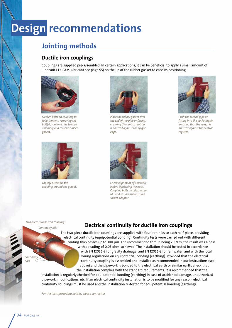
94 - PAM Cast iron
Ductile iron couplingsCouplings are supplied pre-assembled. In certain applications, it can be beneficial to apply a small amount of lubricant ( i.e PAM lubricant see page 95) on the lip of the rubber gasket to ease its positioning.
Electrical continuity for ductile iron couplingsThe two-piece ductile iron couplings are supplied with four iron nibs to each half-piece, providing
electrical continuity (equipotential bonding). Continuity tests were carried out with different coating thicknesses up to 300 µm. The recommended torque being 20 N.m, the result was a pass
with a reading of 0.03 ohm achieved. The installation should be tested in accordance with EN 12056-2 for gravity drainage, and EN 12056-3 for rainwater, and with the local wiring regulations on equipotential bonding (earthing). Provided that the electrical continuity coupling is assembled and installed as recommended in our instructions (see
above) and the pipework is bonded to the electrical earth or similar earth, check that the installation complies with the standard requirements. It is recommended that the
installation is regularly checked for equipotential bonding (earthing) in case of accidental damage, unauthorized pipework, modifications, etc. If an electrical continuity installation is to be modified for any reason, electrical continuity couplings must be used and the installation re-tested for equipotential bonding (earthing).
For the tests procedure details, please contact us
Slacken bolts on coupling to fullest extent, removing the bolt(s) from one side to ease assembly and remove rubber gasket.
Check alignment of assembly before tightening the bolts. Coupling bolts on all sizes are M8 and require special allen socket adaptor.
Loosely assemble the coupling around the gasket.
Push the second pipe or fitting into the gasket again ensuring that the spigot is abutted against the central register.
Place the rubber gasket over the end of the pipe or fitting, ensuring the central register is abutted against the spigot edge.
Design recommendationsJointing methods
Two-piece ductile iron couplings
Continuity nibs
Continuity nibs
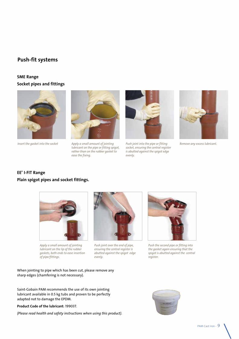
PAM Cast iron - 95
Push-fit systems
When jointing to pipe which has been cut, please remove any sharp edges (chamfering is not necessary).
Saint-Gobain PAM recommends the use of its own jointing lubricant available in 0.5 kg tubs and proven to be perfectly adapted not to damage the EPDM.
Product Code of the lubricant: 199037.
(Please read health and safety instructions when using this product).
SME Range Socket pipes and fittings
EEZI-FIT RangePlain spigot pipes and socket fittings.
Insert the gasket into the socket Apply a small amount of jointing lubricant on the pipe or fitting spigot, rather than on the rubber gasket to ease the fixing.
Push joint into the pipe or fitting socket, ensuring the central register is abutted against the spigot edge evenly.
Remove any excess lubricant.
Push joint over the end of pipe, ensuring the central register is abutted against the spigot edge evenly.
Apply a small amount of jointing lubricant on the lip of the rubber gaskets, both ends to ease insertion of pipe/fittings.
Push the second pipe or fitting into the gasket again ensuring that the spigot is abutted against the central register.
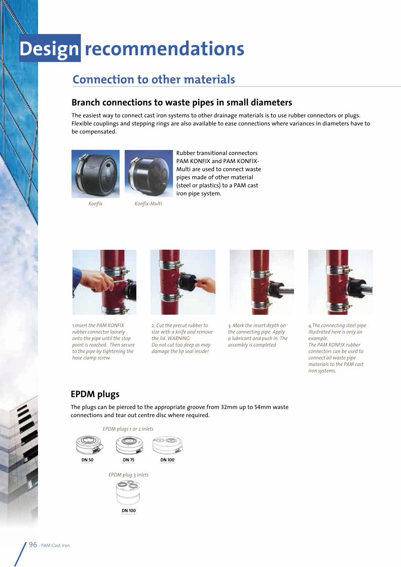
Rubber transitional connectors PAM KONFIX and PAM KONFIX-Multi are used to connect waste pipes made of other material (steel or plastics) to a PAM cast iron pipe system.
Branch connections to waste pipes in small diametersThe easiest way to connect cast iron systems to other drainage materials is to use rubber connectors or plugs. Flexible couplings and stepping rings are also available to ease connections where variances in diameters have to be compensated.
Design recommendationsConnection to other materials
1.Insert the PAM KONFIX rubber connector loosely onto the pipe until the stop point is reached. Then secure to the pipe by tightening the hose clamp screw.
2. Cut the precut rubber to size with a knife and remove the lid. WARNING: Do not cut too deep as may damage the lip seal inside!
3. Mark the insert depth on the connecting pipe. Apply a lubricant and push in. The assembly is completed
4.The connecting steel pipe illustrated here is only an example. The PAM KONFIX rubber connectors can be used to connect all waste pipe materials to the PAM cast iron systems.
96 - PAM Cast iron
Konfix Konfix-Multi
EPDM plugsThe plugs can be pierced to the appropriate groove from 32mm up to 54mm waste connections and tear out centre disc where required.
DN 100
DN 50 DN 75 DN 100
EPDM plugs 1 or 2 inlets
EPDM plug 3 inlets
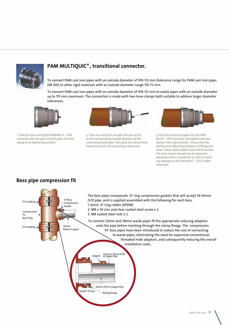
PAM Cast iron - 97
PAM MULTIQUICK, transitional connector.
To connect PAM cast iron pipes with an outside diameter of 109-112 mm (tolerance range for PAM cast iron pipes DN 100) to other rigid materials with an outside diameter range 110-72 mm.
To connect PAM cast iron pipes with an outside diameter of 109-112 mm to waste pipes with an outside diameter up to 115 mm maximum. The connection is made with two hose clamps both suitable to address larger diameter tolerances.
Boss pipe compression fit
Connection to other materials
1. Push the open end of the PAM MULTIQUICK connector over the pipe end and place the hose clamp to its tightening position.
2. Then use a knife to cut open the pre cut lid to the corresponding outside diameter of the connecting waste pipe. Then push the second hose clamp loose over the connecting rubber end.
3. Push the connecting pipe into the PAM MULTIQUICK connector and tighten the hose clamp in the right position. Ensure that the sealing zones (face ends of pipes or fittings) are clean: remove paint flakes and cement residues. The hose clamps should only be tightened manually with a screwdriver in order to avoid any damage to the PAM MULTIQUICK rubber connector.
The boss pipes incorporate ‘O’ ring compression gaskets that will accept 54-56mm O/D pipe, and is supplied assembled with the following for each boss. 1. 6mm ‘O’ ring rubber (EPDM) 2. M8 x 30 zinc and clear coated steel screw x 2 3. M8 coated steel nuts x 2
To connect 32mm and 38mm waste pipes fit the appropriate reducing adaptors onto the pipe before inserting through the clamp flange. The ‘compression
fit’ boss pipes have been introduced to reduce the cost of connecting to waste pipes, eliminating the need for expensive conventional
threaded male adaptors, and subsequently reducing the overall installation costs.
DI coupling
CompressionFitBoss Pipe
DI coupling
‘0’ RingCompressionGasket�
�
�
�
�
50mmPlastic/Copper
�
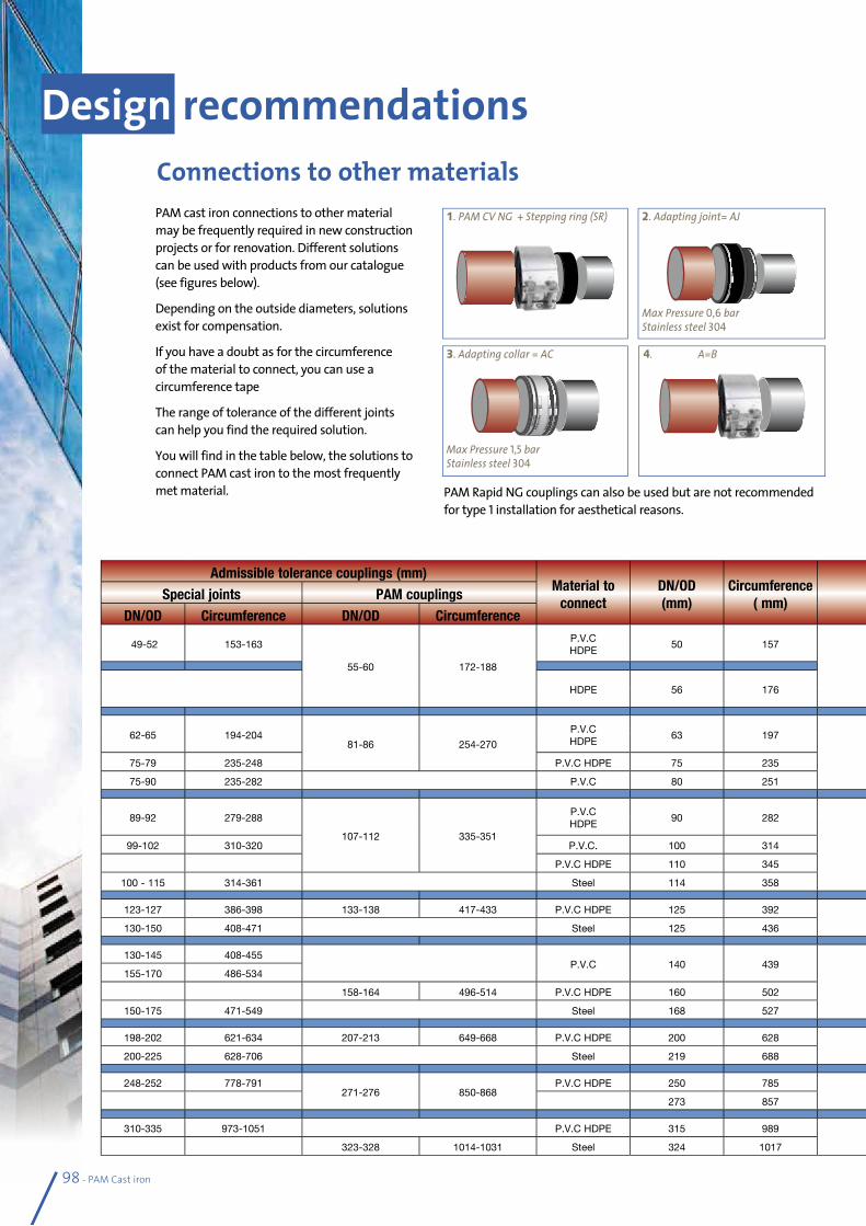
98 - PAM Cast iron
Design recommendationsConnections to other materialsPAM cast iron connections to other material may be frequently required in new construction projects or for renovation. Different solutions can be used with products from our catalogue (see figures below).
Depending on the outside diameters, solutions exist for compensation.
If you have a doubt as for the circumference of the material to connect, you can use a circumference tape
The range of tolerance of the different joints can help you find the required solution.
You will find in the table below, the solutions to connect PAM cast iron to the most frequently met material.
3. Adapting collar = AC
Max Pressure 1,5 barStainless steel 304
1. PAM CV NG + Stepping ring (SR)
4. A=B
2. Adapting joint= AJ
Max Pressure 0,6 barStainless steel 304
Admissible tolerance couplings (mm)Material to
connectDN/OD (mm)
Circumference ( mm)
PAM cast ironDN (mm)
DN/OD (mm)
DN/OD Tolerance
(mm)Solution Junctions product codes FigureSpecial joints PAM couplings
DN/OD Circumference DN/OD Circumference
49-52 153-163
55-60 172-188
P.V.C HDPE
50 157
50 58+ 2 -1
PAM CV NG + BC 210398 -156399 1
SMU PAM R + BC 233899 - 156399
HDPE 56 176PAM CV NG 210398
4SMU PAM R 233899
62-65 194-20481-86 254-270
P.V.C HDPE
63 197
75 83+2 -1
PAM CV NG + BC 210413 -1564951
SMU PAM R + BC 233900 -156495
75-79 235-248 P.V.C HDPE 75 235 PAM CV NG +BC 210413 -156494 1
75-90 235-282 P.V.C 80 251 SMU ”MA” 155001 3
89-92 279-288
107-112 335-351
P.V.C HDPE
90 282
100 110+2 -1
PAM CV NG + BC 210416 -1565551
SMU PAM R + BC 233901 - 156555
99-102 310-320 P.V.C. 100 314 PAM CV NG +BC 210416 - 156635 1
P.V.C HDPE 110 345 PAM CV NG 210416 4
100 - 115 314-361 Steel 114 358 SMU ”MA” 155002 3
123-127 386-398 133-138 417-433 P.V.C HDPE 125 392125 135
+2 -2
PAM CV NG + BC 210417 + 156778 1
130-150 408-471 Steel 125 436 SMU ”MA” TXB12NLOG 3
130-145 408-455P.V.C 140 439
150 160+2 -2
SMU “RA” 155003 2155-170 486-534
158-164 496-514 P.V.C HDPE 160 502 PAM CV NG 210418 4
150-175 471-549 Steel 168 527 SMU ”MA” TXB15NMOJ 3
198-202 621-634 207-213 649-668 P.V.C HDPE 200 628200 210
+2,5 -2,5
PAM CV NG + SR 210420 + 157000 1
200-225 628-706 Steel 219 688 SMU ”MA” TXB20NLOK 3
248-252 778-791271-276 850-868
P.V.C HDPE 250 785250 274
+2,5 -2,5
PAM CV NG + SR 210422 + 157085 1
273 857 PAM CV NG 210422 4
310-335 973-1051 P.V.C HDPE 315 989300 326
+2,5 -2,5
SMU“MA” TXB30NN02 3
323-328 1014-1031 Steel 324 1017 PAM CV NG 210423 4
PAM Rapid NG couplings can also be used but are not recommended for type 1 installation for aesthetical reasons.
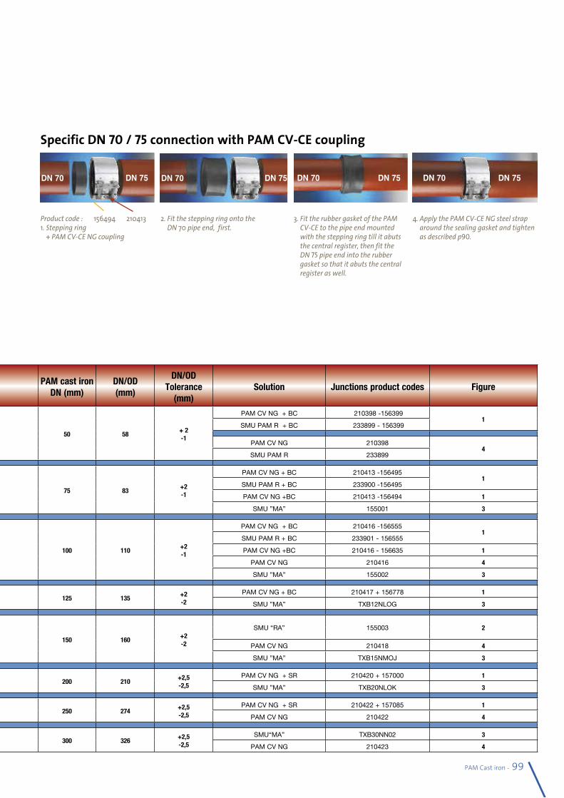
PAM Cast iron - 99
Specific DN 70 / 75 connection with PAM CV-CE coupling
3. Fit the rubber gasket of the PAM CV-CE to the pipe end mounted with the stepping ring till it abuts the central register, then fit the DN 75 pipe end into the rubber gasket so that it abuts the central register as well.
DN 70 DN 75
4. Apply the PAM CV-CE NG steel strap around the sealing gasket and tighten as described p90.
DN 70 DN 75
2. Fit the stepping ring onto the DN 70 pipe end, first.
DN 70 DN 75
Product code : 156494 2104131. Stepping ring
+ PAM CV-CE NG coupling
DN 70 DN 75
Admissible tolerance couplings (mm)Material to
connectDN/OD (mm)
Circumference ( mm)
PAM cast ironDN (mm)
DN/OD (mm)
DN/OD Tolerance
(mm)Solution Junctions product codes FigureSpecial joints PAM couplings
DN/OD Circumference DN/OD Circumference
49-52 153-163
55-60 172-188
P.V.C HDPE
50 157
50 58+ 2 -1
PAM CV NG + BC 210398 -156399 1
SMU PAM R + BC 233899 - 156399
HDPE 56 176PAM CV NG 210398
4SMU PAM R 233899
62-65 194-20481-86 254-270
P.V.C HDPE
63 197
75 83+2 -1
PAM CV NG + BC 210413 -1564951
SMU PAM R + BC 233900 -156495
75-79 235-248 P.V.C HDPE 75 235 PAM CV NG +BC 210413 -156494 1
75-90 235-282 P.V.C 80 251 SMU ”MA” 155001 3
89-92 279-288
107-112 335-351
P.V.C HDPE
90 282
100 110+2 -1
PAM CV NG + BC 210416 -1565551
SMU PAM R + BC 233901 - 156555
99-102 310-320 P.V.C. 100 314 PAM CV NG +BC 210416 - 156635 1
P.V.C HDPE 110 345 PAM CV NG 210416 4
100 - 115 314-361 Steel 114 358 SMU ”MA” 155002 3
123-127 386-398 133-138 417-433 P.V.C HDPE 125 392125 135
+2 -2
PAM CV NG + BC 210417 + 156778 1
130-150 408-471 Steel 125 436 SMU ”MA” TXB12NLOG 3
130-145 408-455P.V.C 140 439
150 160+2 -2
SMU “RA” 155003 2155-170 486-534
158-164 496-514 P.V.C HDPE 160 502 PAM CV NG 210418 4
150-175 471-549 Steel 168 527 SMU ”MA” TXB15NMOJ 3
198-202 621-634 207-213 649-668 P.V.C HDPE 200 628200 210
+2,5 -2,5
PAM CV NG + SR 210420 + 157000 1
200-225 628-706 Steel 219 688 SMU ”MA” TXB20NLOK 3
248-252 778-791271-276 850-868
P.V.C HDPE 250 785250 274
+2,5 -2,5
PAM CV NG + SR 210422 + 157085 1
273 857 PAM CV NG 210422 4
310-335 973-1051 P.V.C HDPE 315 989300 326
+2,5 -2,5
SMU“MA” TXB30NN02 3
323-328 1014-1031 Steel 324 1017 PAM CV NG 210423 4
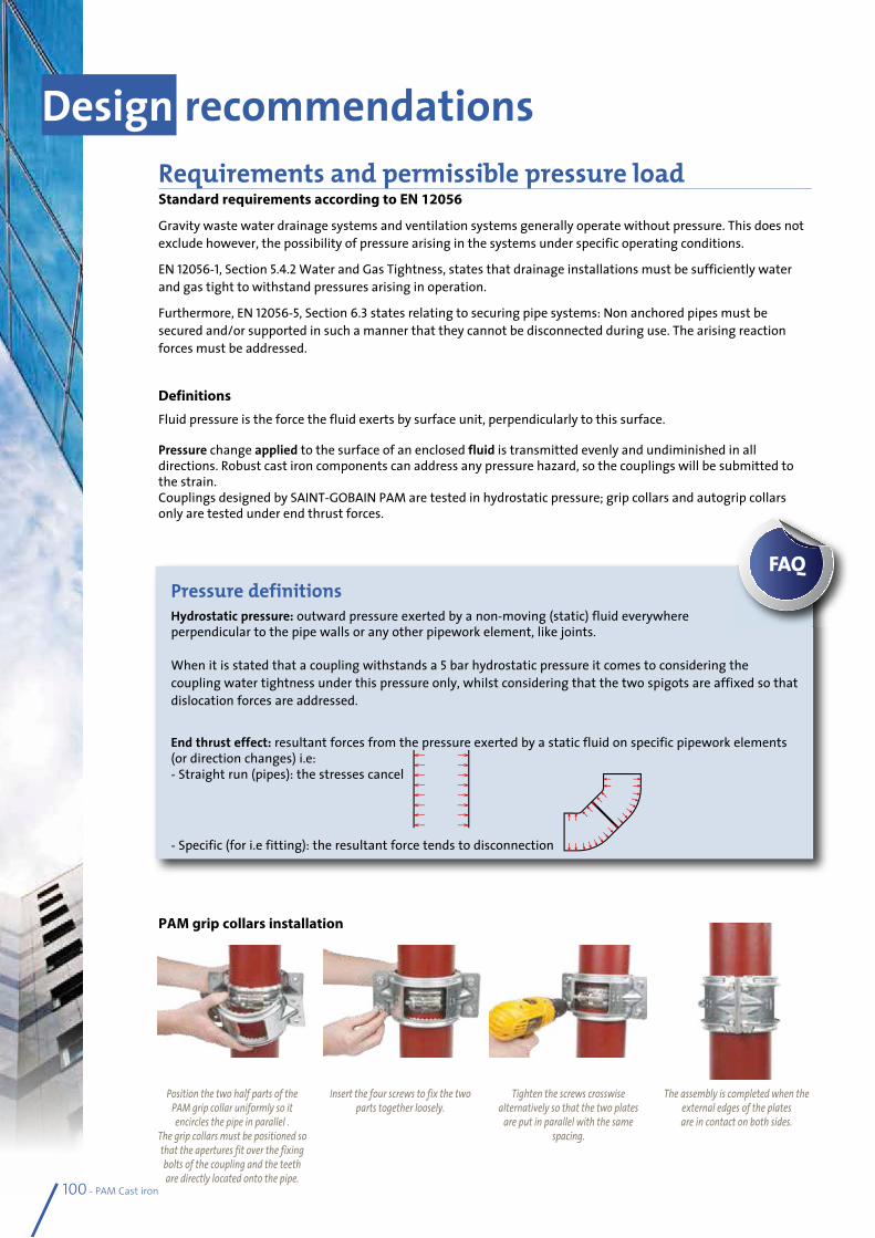
100 - PAM Cast iron
Design recommendationsRequirements and permissible pressure loadStandard requirements according to EN 12056
Gravity waste water drainage systems and ventilation systems generally operate without pressure. This does not exclude however, the possibility of pressure arising in the systems under specific operating conditions.
EN 12056-1, Section 5.4.2 Water and Gas Tightness, states that drainage installations must be sufficiently water and gas tight to withstand pressures arising in operation.
Furthermore, EN 12056-5, Section 6.3 states relating to securing pipe systems: Non anchored pipes must be secured and/or supported in such a manner that they cannot be disconnected during use. The arising reaction forces must be addressed.
Definitions
Fluid pressure is the force the fluid exerts by surface unit, perpendicularly to this surface.
Pressure change applied to the surface of an enclosed fluid is transmitted evenly and undiminished in all directions. Robust cast iron components can address any pressure hazard, so the couplings will be submitted to the strain. Couplings designed by SAINT-GOBAIN PAM are tested in hydrostatic pressure; grip collars and autogrip collars only are tested under end thrust forces.
PAM grip collars installation
Pressure definitionsHydrostatic pressure: outward pressure exerted by a non-moving (static) fluid everywhere perpendicular to the pipe walls or any other pipework element, like joints.
When it is stated that a coupling withstands a 5 bar hydrostatic pressure it comes to considering the coupling water tightness under this pressure only, whilst considering that the two spigots are affixed so that dislocation forces are addressed.
End thrust effect: resultant forces from the pressure exerted by a static fluid on specific pipework elements (or direction changes) i.e:- Straight run (pipes): the stresses cancel
- Specific (for i.e fitting): the resultant force tends to disconnection
FAQ
Position the two half parts of the PAM grip collar uniformly so it encircles the pipe in parallel .
The grip collars must be positioned so that the apertures fit over the fixing bolts of the coupling and the teeth are directly located onto the pipe.
Insert the four screws to fix the two parts together loosely.
Tighten the screws crosswise alternatively so that the two plates
are put in parallel with the same spacing.
The assembly is completed when the external edges of the plates are in contact on both sides.
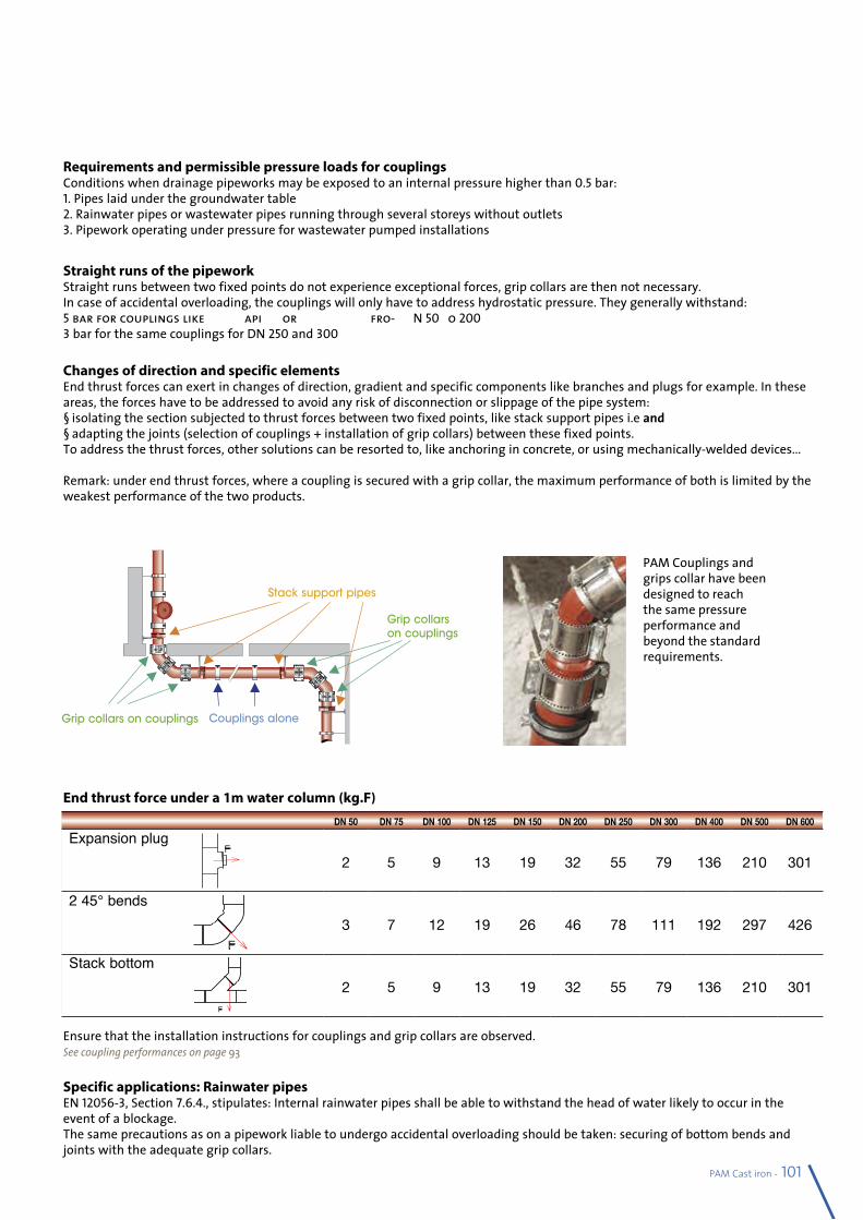
DN 50 DN 75 DN 100 DN 125 DN 150 DN 200 DN 250 DN 300 DN 400 DN 500 DN 600
Expansion plug2 5 9 13 19 32 55 79 136 210 301
2 45° bends3 7 12 19 26 46 78 111 192 297 426
Stack bottom2 5 9 13 19 32 55 79 136 210 301
PAM Cast iron - 101
Requirements and permissible pressure loads for couplingsConditions when drainage pipeworks may be exposed to an internal pressure higher than 0.5 bar:1. Pipes laid under the groundwater table2. Rainwater pipes or wastewater pipes running through several storeys without outlets3. Pipework operating under pressure for wastewater pumped installations
Straight runs of the pipeworkStraight runs between two fixed points do not experience exceptional forces, grip collars are then not necessary.In case of accidental overloading, the couplings will only have to address hydrostatic pressure. They generally withstand:5 bar for couplings like PAM Rapid S or SMU PAM R from DN 50 to 2003 bar for the same couplings for DN 250 and 300
Changes of direction and specific elementsEnd thrust forces can exert in changes of direction, gradient and specific components like branches and plugs for example. In these areas, the forces have to be addressed to avoid any risk of disconnection or slippage of the pipe system:• isolating the section subjected to thrust forces between two fixed points, like stack support pipes i.e and• adapting the joints (selection of couplings + installation of grip collars) between these fixed points.To address the thrust forces, other solutions can be resorted to, like anchoring in concrete, or using mechanically-welded devices...
Remark: under end thrust forces, where a coupling is secured with a grip collar, the maximum performance of both is limited by the weakest performance of the two products.
End thrust force under a 1m water column (kg.F)
Specific applications: Rainwater pipesEN 12056-3, Section 7.6.4., stipulates: Internal rainwater pipes shall be able to withstand the head of water likely to occur in theevent of a blockage.The same precautions as on a pipework liable to undergo accidental overloading should be taken: securing of bottom bends and joints with the adequate grip collars.
Stack support pipes
Grip collars on couplings
Grip collars on couplings Couplings alone
Ensure that the installation instructions for couplings and grip collars are observed.See coupling performances on page 93
PAM Couplings and grips collar have been designed to reach the same pressure performance and beyond the standard requirements.
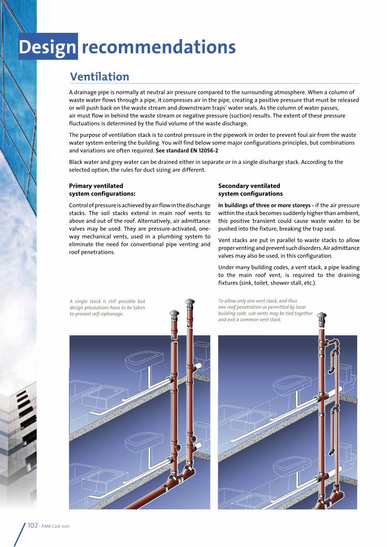
102 - PAM Cast iron
A drainage pipe is normally at neutral air pressure compared to the surrounding atmosphere. When a column of waste water flows through a pipe, it compresses air in the pipe, creating a positive pressure that must be released or will push back on the waste stream and downstream traps’ water seals. As the column of water passes, air must flow in behind the waste stream or negative pressure (suction) results. The extent of these pressure fluctuations is determined by the fluid volume of the waste discharge.
The purpose of ventilation stack is to control pressure in the pipework in order to prevent foul air from the waste water system entering the building. You will find below some major configurations principles, but combinations and variations are often required. See standard EN 12056-2
Black water and grey water can be drained either in separate or in a single discharge stack. According to the selected option, the rules for duct sizing are different.
Design recommendationsVentilation
Primary ventilated system configurations:
Control of pressure is achieved by air flow in the discharge stacks. The soil stacks extend in main roof vents to above and out of the roof. Alternatively, air admittance valves may be used. They are pressure-activated, one-way mechanical vents, used in a plumbing system to eliminate the need for conventional pipe venting and roof penetrations.
Secondary ventilated system configurations
In buildings of three or more storeys - if the air pressure within the stack becomes suddenly higher than ambient, this positive transient could cause waste water to be pushed into the fixture, breaking the trap seal.
Vent stacks are put in parallel to waste stacks to allow proper venting and prevent such disorders. Air admittance valves may also be used, in this configuration.
Under many building codes, a vent stack, a pipe leading to the main roof vent, is required to the draining fixtures (sink, toilet, shower stall, etc.).
To allow only one vent stack, and thus one roof penetration as permitted by local building code, sub-vents may be tied together and exit a common vent stack.
A single stack is still possible but design precautions have to be taken to prevent self-siphonage.
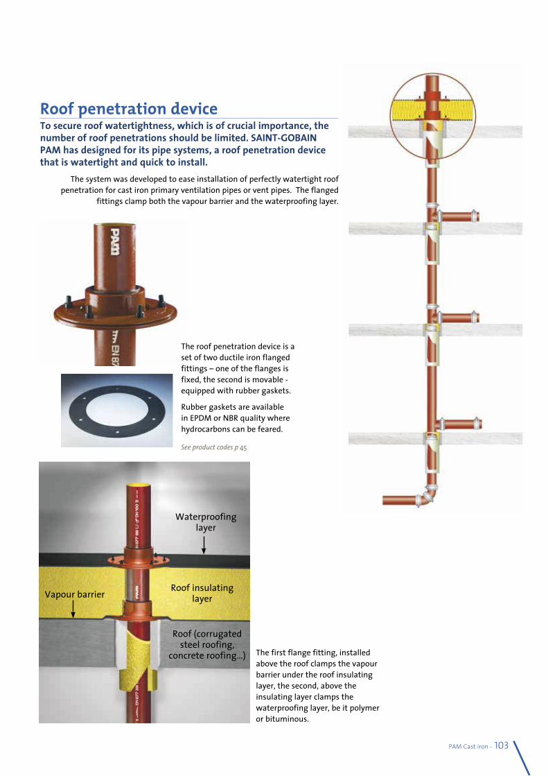
PAM Cast iron - 103
Roof penetration deviceTo secure roof watertightness, which is of crucial importance, the number of roof penetrations should be limited. SAINT-GOBAIN PAM has designed for its pipe systems, a roof penetration device that is watertight and quick to install.
The system was developed to ease installation of perfectly watertight roof penetration for cast iron primary ventilation pipes or vent pipes. The flanged
fittings clamp both the vapour barrier and the waterproofing layer.
The first flange fitting, installed above the roof clamps the vapour barrier under the roof insulating layer, the second, above the insulating layer clamps the waterproofing layer, be it polymer or bituminous.
Roof insulating layer
Roof (corrugated steel roofing,
concrete roofing…)
Vapour barrier
Waterproofing layer
The roof penetration device is a set of two ductile iron flanged fittings – one of the flanges is fixed, the second is movable - equipped with rubber gaskets.
Rubber gaskets are available in EPDM or NBR quality where hydrocarbons can be feared.
See product codes p 45
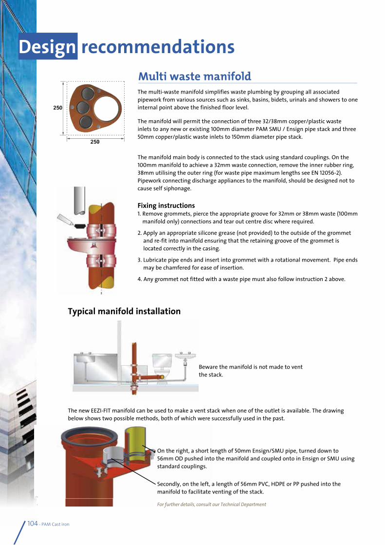
Typical manifold installation
The multi-waste manifold simplifies waste plumbing by grouping all associated pipework from various sources such as sinks, basins, bidets, urinals and showers to one internal point above the finished floor level.
The manifold will permit the connection of three 32/38mm copper/plastic waste inlets to any new or existing 100mm diameter PAM SMU / Ensign pipe stack and three 50mm copper/plastic waste inlets to 150mm diameter pipe stack.
The manifold main body is connected to the stack using standard couplings. On the 100mm manifold to achieve a 32mm waste connection, remove the inner rubber ring, 38mm utilising the outer ring (for waste pipe maximum lengths see EN 12056-2). Pipework connecting discharge appliances to the manifold, should be designed not to cause self siphonage.
Fixing instructions 1. Remove grommets, pierce the appropriate groove for 32mm or 38mm waste (100mm
manifold only) connections and tear out centre disc where required.
2. Apply an appropriate silicone grease (not provided) to the outside of the grommet and re-fit into manifold ensuring that the retaining groove of the grommet is located correctly in the casing.
3. Lubricate pipe ends and insert into grommet with a rotational movement. Pipe ends may be chamfered for ease of insertion.
4. Any grommet not fitted with a waste pipe must also follow instruction 2 above.
Beware the manifold is not made to vent the stack.
The new EEZI-FIT manifold can be used to make a vent stack when one of the outlet is available. The drawing below shows two possible methods, both of which were successfully used in the past.
Design recommendationsMulti waste manifold
104 - PAM Cast iron
On the right, a short length of 50mm Ensign/SMU pipe, turned down to 56mm OD pushed into the manifold and coupled onto in Ensign or SMU using standard couplings.
Secondly, on the left, a length of 56mm PVC, HDPE or PP pushed into the manifold to facilitate venting of the stack.
For further details, consult our Technical Department
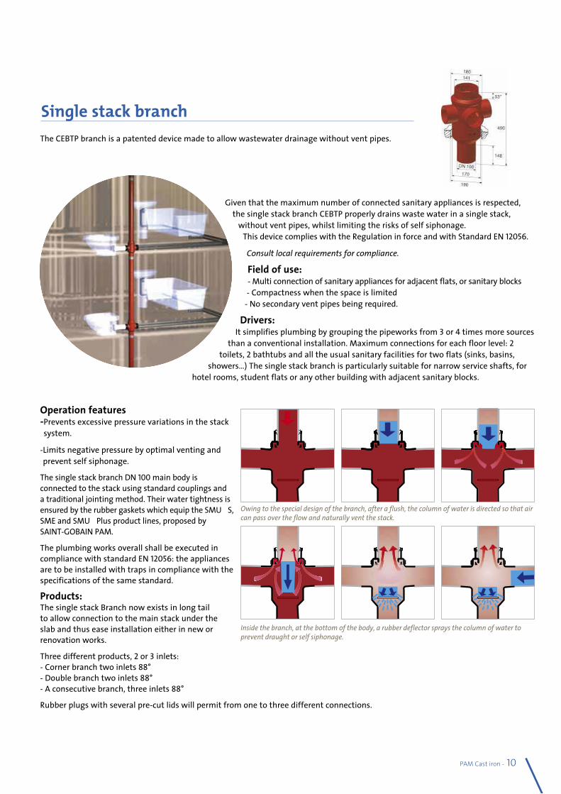
PAM Cast iron - 105
The CEBTP branch is a patented device made to allow wastewater drainage without vent pipes.
Given that the maximum number of connected sanitary appliances is respected, the single stack branch CEBTP properly drains waste water in a single stack,
without vent pipes, whilst limiting the risks of self siphonage. This device complies with the Regulation in force and with Standard EN 12056.
Consult local requirements for compliance.
Field of use: - Multi connection of sanitary appliances for adjacent flats, or sanitary blocks - Compactness when the space is limited
- No secondary vent pipes being required.
Drivers: It simplifies plumbing by grouping the pipeworks from 3 or 4 times more sources
than a conventional installation. Maximum connections for each floor level: 2 toilets, 2 bathtubs and all the usual sanitary facilities for two flats (sinks, basins,
showers…) The single stack branch is particularly suitable for narrow service shafts, for hotel rooms, student flats or any other building with adjacent sanitary blocks.
Operation features - Prevents excessive pressure variations in the stack system.
- Limits negative pressure by optimal venting and prevent self siphonage.
The single stack branch DN 100 main body is connected to the stack using standard couplings and a traditional jointing method. Their water tightness is ensured by the rubber gaskets which equip the SMU® S, SME and SMU® Plus product lines, proposed by SAINT-GOBAIN PAM.
The plumbing works overall shall be executed in compliance with standard EN 12056: the appliances are to be installed with traps in compliance with the specifications of the same standard.
Products: The single stack Branch now exists in long tail to allow connection to the main stack under the slab and thus ease installation either in new or renovation works.
Three different products, 2 or 3 inlets: - Corner branch two inlets 88° - Double branch two inlets 88° - A consecutive branch, three inlets 88°
Rubber plugs with several pre-cut lids will permit from one to three different connections.
Single stack branch
Owing to the special design of the branch, after a flush, the column of water is directed so that air can pass over the flow and naturally vent the stack.
Inside the branch, at the bottom of the body, a rubber deflector sprays the column of water to prevent draught or self siphonage.
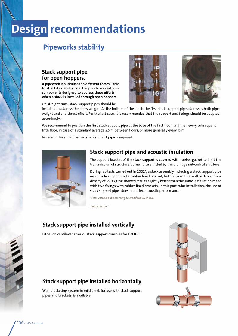
Stack support pipe installed vertically
Stack support pipe installed horizontally
Stack support pipe for open hoppers.A pipework is submitted to different forces liable to affect its stability. Stack supports are cast iron components designed to address these efforts when a stack is installed through open hoppers.
On straight runs, stack support pipes should be installed to address the pipes weight. At the bottom of the stack, the first stack support pipe addresses both pipes weight and end thrust effort. For the last case, it is recommended that the support and fixings should be adapted accordingly.
We recommend to position the first stack support pipe at the base of the first floor, and then every subsequent fifth floor, in case of a standard average 2.5 m between floors, or more generally every 15 m.
In case of closed hopper, no stack support pipe is required.
Stack support pipe and acoustic insulationThe support bracket of the stack support is covered with rubber gasket to limit the transmission of structure-borne noise emitted by the drainage network at slab level.
During lab tests carried out in 2002*, a stack assembly including a stack support pipe on console support and a rubber lined bracket, both affixed to a wall with a surface density of 220 kg/m2 showed results slightly better than the same installation made with two fixings with rubber lined brackets. In this particular installation, the use of stack support pipes does not affect acoustic performance.
*Tests carried out according to standard EN 14366.
Either on cantilever arms or stack support consoles for DN 100.
Wall bracketing system in mild steel, for use with stack support pipes and brackets, is available.
Pipeworks stability
106 - PAM Cast iron
Design recommendations
Rubber gasket
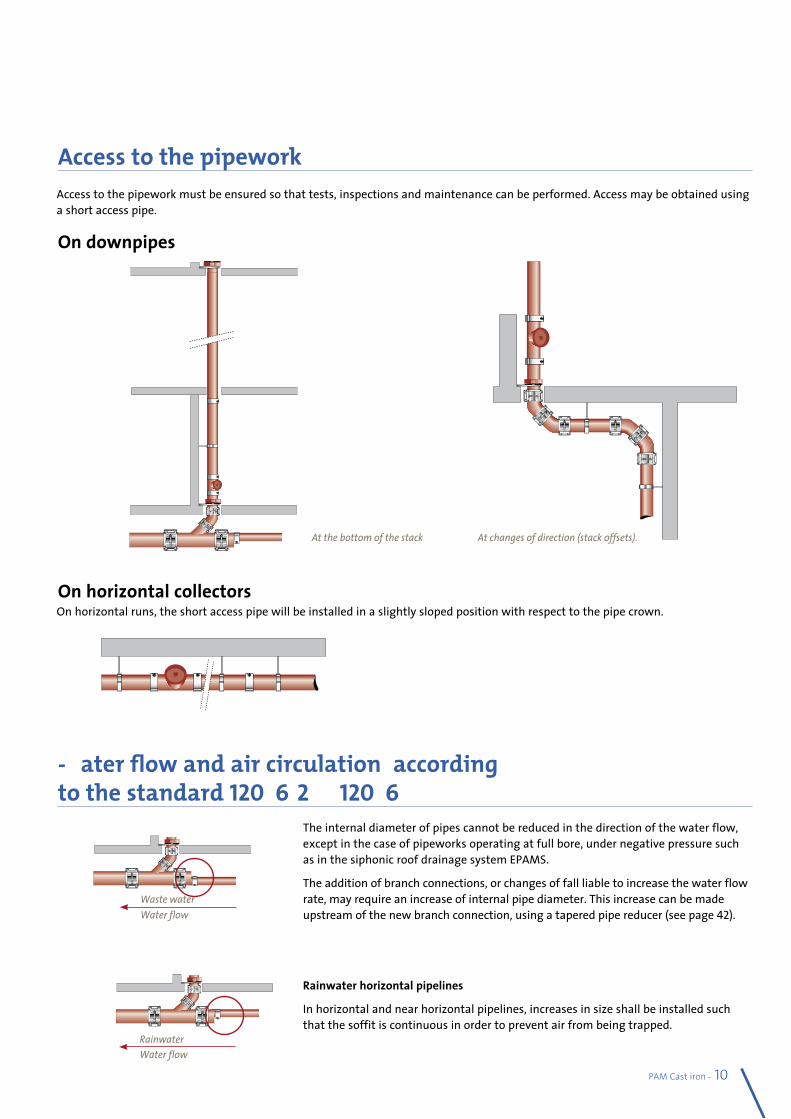
At the bottom of the stack At changes of direction (stack offsets).
Access to the pipework must be ensured so that tests, inspections and maintenance can be performed. Access may be obtained using a short access pipe.
On horizontal runs, the short access pipe will be installed in a slightly sloped position with respect to the pipe crown.
Access to the pipework
Water flow and air circulation, according to the standard 12056-2 & 12056-3.
The internal diameter of pipes cannot be reduced in the direction of the water flow, except in the case of pipeworks operating at full bore, under negative pressure such as in the siphonic roof drainage system EPAMS.
The addition of branch connections, or changes of fall liable to increase the water flow rate, may require an increase of internal pipe diameter. This increase can be made upstream of the new branch connection, using a tapered pipe reducer (see page 42).
Rainwater horizontal pipelines
In horizontal and near horizontal pipelines, increases in size shall be installed such that the soffit is continuous in order to prevent air from being trapped.
On downpipes
On horizontal collectors
PAM Cast iron - 107Water flowRainwater
Water flowWaste water
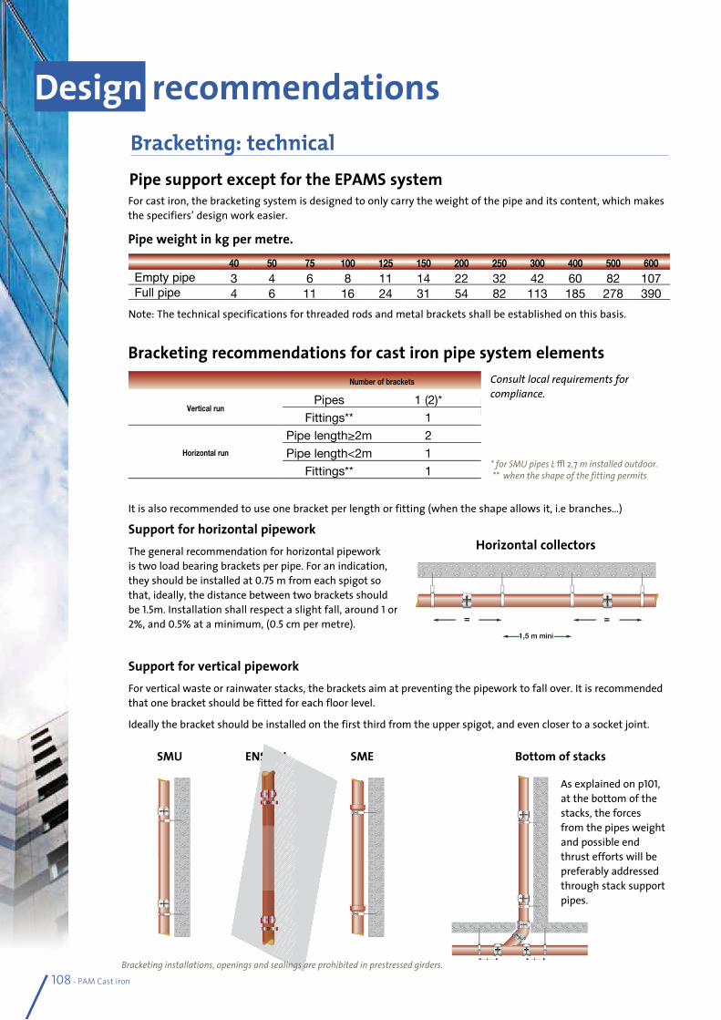
40 50 75 100 125 150 200 250 300 400 500 600Empty pipe 3 4 6 8 11 14 22 32 42 60 82 107Full pipe 4 6 11 16 24 31 54 82 113 185 278 390
Pipe support except for the EPAMS systemFor cast iron, the bracketing system is designed to only carry the weight of the pipe and its content, which makes the specifiers’ design work easier.
Note: The technical specifications for threaded rods and metal brackets shall be established on this basis.
It is also recommended to use one bracket per length or fitting (when the shape allows it, i.e branches…)
Support for horizontal pipeworkThe general recommendation for horizontal pipework is two load bearing brackets per pipe. For an indication, they should be installed at 0.75 m from each spigot so that, ideally, the distance between two brackets should be 1.5m. Installation shall respect a slight fall, around 1 or 2%, and 0.5% at a minimum, (0.5 cm per metre).
Support for vertical pipeworkFor vertical waste or rainwater stacks, the brackets aim at preventing the pipework to fall over. It is recommended that one bracket should be fitted for each floor level.
Ideally the bracket should be installed on the first third from the upper spigot, and even closer to a socket joint.
Pipe weight in kg per metre.
Bracketing recommendations for cast iron pipe system elements
SMU ENSIGN SME Bottom of stacks
Design recommendationsBracketing: technical
Number of brackets
Vertical runPipes 1 (2)*
Fittings** 1
Horizontal run
Pipe length≥2m 2
Pipe length<2m 1
Fittings** 1
108 - PAM Cast iron
1,5 m mini
= =
Horizontal collectors
Consult local requirements for compliance.
* for SMU pipes L ≥ 2,7 m installed outdoor. ** when the shape of the fitting permits
Bracketing installations, openings and sealings are prohibited in prestressed girders.
As explained on p101, at the bottom of the stacks, the forces from the pipes weight and possible end thrust efforts will be preferably addressed through stack support pipes.
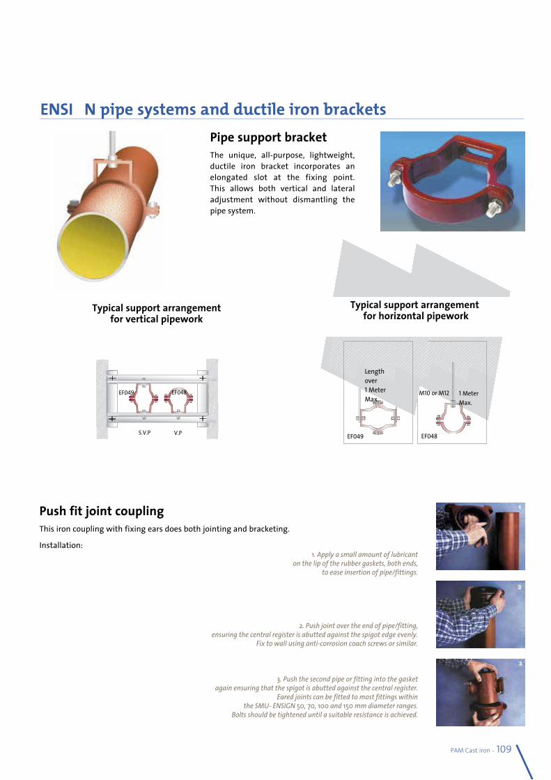
Pipe support bracketThe unique, all-purpose, lightweight, ductile iron bracket incorporates an elongated slot at the fixing point. This allows both vertical and lateral adjustment without dismantling the pipe system.
Push fit joint couplingThis iron coupling with fixing ears does both jointing and bracketing.
Installation:1. Apply a small amount of lubricant
on the lip of the rubber gaskets, both ends, to ease insertion of pipe/fittings.
2. Push joint over the end of pipe/fitting, ensuring the central register is abutted against the spigot edge evenly.
Fix to wall using anti-corrosion coach screws or similar.
3. Push the second pipe or fitting into the gasket again ensuring that the spigot is abutted against the central register.
Eared joints can be fitted to most fittings within the SMU- ENSIGN 50, 70, 100 and 150 mm diameter ranges.
Bolts should be tightened until a suitable resistance is achieved.
ENSIGN pipe systems and ductile iron brackets.
PAM Cast iron - 109
EF048
1 Meter Max.
EF049
Length over 1 Meter Max.
M10 or M12
Typical support arrangement for vertical pipework
Typical support arrangement for horizontal pipework
EF049 EF048
S.V.P V.P
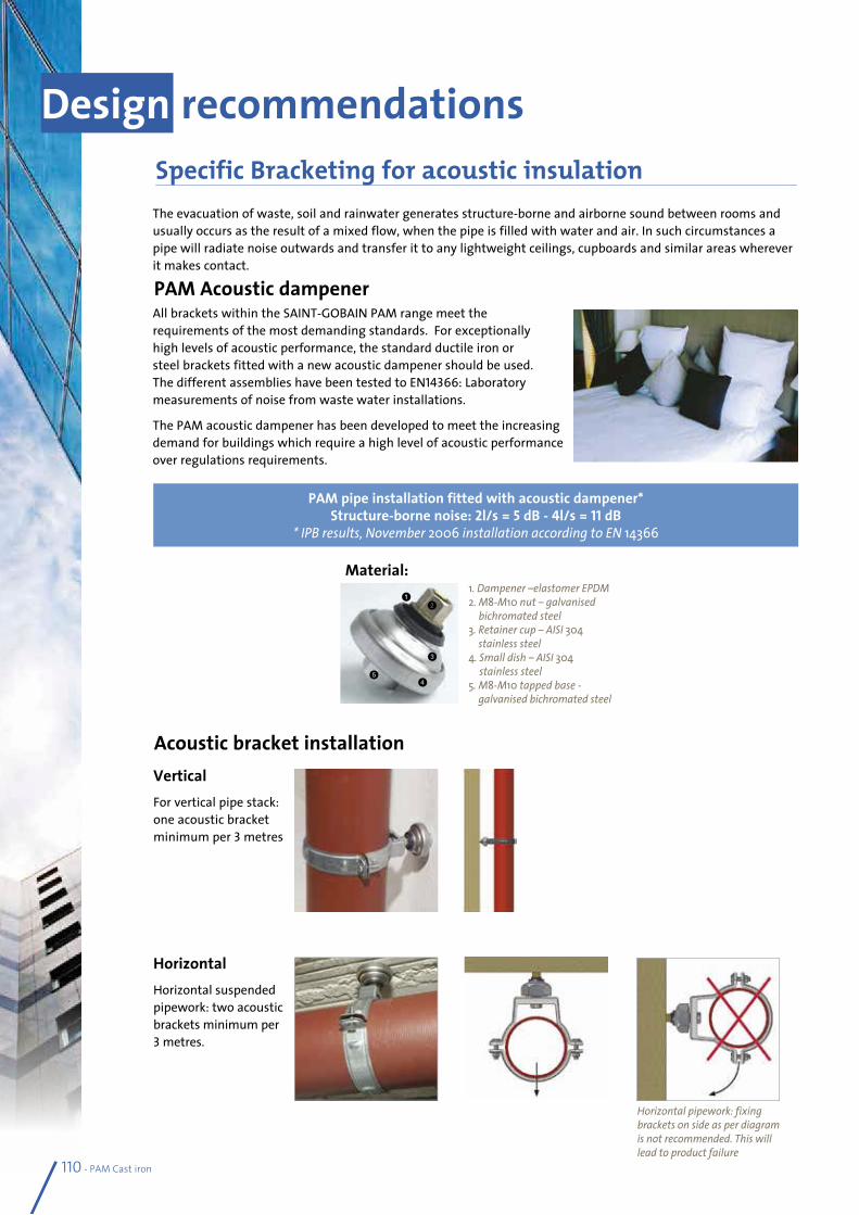
PAM Acoustic dampener
Acoustic bracket installation
The evacuation of waste, soil and rainwater generates structure-borne and airborne sound between rooms and usually occurs as the result of a mixed flow, when the pipe is filled with water and air. In such circumstances a pipe will radiate noise outwards and transfer it to any lightweight ceilings, cupboards and similar areas wherever it makes contact.
Horizontal pipework: fixing brackets on side as per diagram is not recommended. This will lead to product failure
All brackets within the SAINT-GOBAIN PAM range meet the requirements of the most demanding standards. For exceptionally high levels of acoustic performance, the standard ductile iron or steel brackets fitted with a new acoustic dampener should be used. The different assemblies have been tested to EN14366: Laboratory measurements of noise from waste water installations.
The PAM acoustic dampener has been developed to meet the increasing demand for buildings which require a high level of acoustic performance over regulations requirements.
PAM pipe installation fitted with acoustic dampener* Structure-borne noise: 2l/s = 5 dB - 4l/s = 11 dB
* IPB results, November 2006 installation according to EN 14366
Vertical For vertical pipe stack: one acoustic bracket minimum per 3 metres
HorizontalHorizontal suspended pipework: two acoustic brackets minimum per 3 metres.
Design recommendationsSpecific Bracketing for acoustic insulation
Material: 1. Dampener –elastomer EPDM2. M8-M10 nut – galvanised
bichromated steel3. Retainer cup – AISI 304
stainless steel4. Small dish – AISI 304
stainless steel5. M8-M10 tapped base -
galvanised bichromated steel
12
3
45
110 - PAM Cast iron
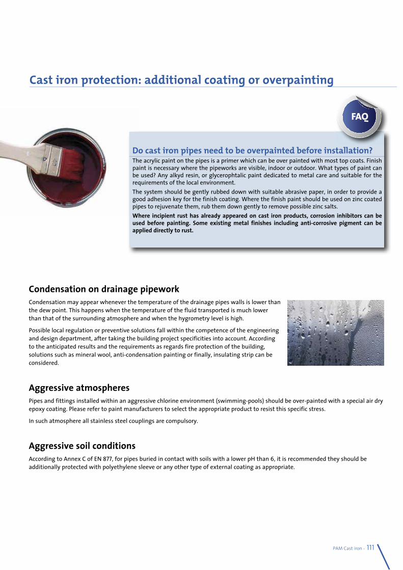
PAM Cast iron - 111
Condensation on drainage pipeworkCondensation may appear whenever the temperature of the drainage pipes walls is lower than the dew point. This happens when the temperature of the fluid transported is much lower than that of the surrounding atmosphere and when the hygrometry level is high.
Possible local regulation or preventive solutions fall within the competence of the engineering and design department, after taking the building project specificities into account. According to the anticipated results and the requirements as regards fire protection of the building, solutions such as mineral wool, anti-condensation painting or finally, insulating strip can be considered.
Aggressive atmospheresPipes and fittings installed within an aggressive chlorine environment (swimming-pools) should be over-painted with a special air dry epoxy coating. Please refer to paint manufacturers to select the appropriate product to resist this specific stress.
In such atmosphere all stainless steel couplings are compulsory.
Aggressive soil conditions According to Annex C of EN 877, for pipes buried in contact with soils with a lower pH than 6, it is recommended they should be additionally protected with polyethylene sleeve or any other type of external coating as appropriate.
Cast iron protection: additional coating or overpainting
Do cast iron pipes need to be overpainted before installation? The acrylic paint on the pipes is a primer which can be over painted with most top coats. Finish paint is necessary where the pipeworks are visible, indoor or outdoor. What types of paint can be used? Any alkyd resin, or glycerophtalic paint dedicated to metal care and suitable for the requirements of the local environment.The system should be gently rubbed down with suitable abrasive paper, in order to provide a good adhesion key for the finish coating. Where the finish paint should be used on zinc coated pipes to rejuvenate them, rub them down gently to remove possible zinc salts. Where incipient rust has already appeared on cast iron products, corrosion inhibitors can be used before painting. Some existing metal finishes including anti-corrosive pigment can be applied directly to rust.
FAQ
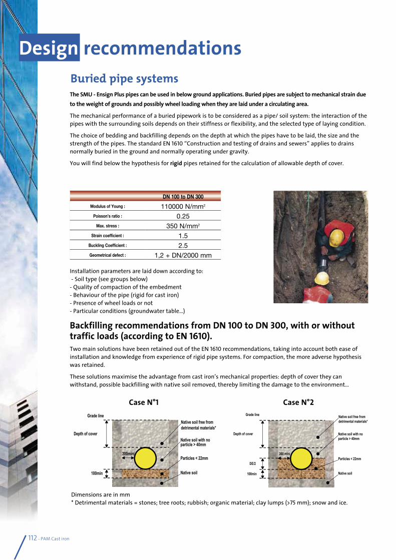
Design recommendations
112 - PAM Cast iron
The SMU - Ensign Plus pipes can be used in below ground applications. Buried pipes are subject to mechanical strain due to the weight of grounds and possibly wheel loading when they are laid under a circulating area.
The mechanical performance of a buried pipework is to be considered as a pipe/ soil system: the interaction of the pipes with the surrounding soils depends on their stiffness or flexibility, and the selected type of laying condition.
The choice of bedding and backfilling depends on the depth at which the pipes have to be laid, the size and the strength of the pipes. The standard EN 1610 “Construction and testing of drains and sewers” applies to drains normally buried in the ground and normally operating under gravity.
You will find below the hypothesis for rigid pipes retained for the calculation of allowable depth of cover.
Installation parameters are laid down according to: - Soil type (see groups below)- Quality of compaction of the embedment - Behaviour of the pipe (rigid for cast iron)- Presence of wheel loads or not- Particular conditions (groundwater table…)
Buried pipe systems
DN 100 to DN 300
Modulus of Young : 110000 N/mm2
Poisson’s ratio : 0.25Max. stress : 350 N/mm2
Strain coefficient : 1.5Buckling Coefficient : 2.5Geometrical defect : 1,2 + DN/2000 mm
Backfilling recommendations from DN 100 to DN 300, with or without traffic loads (according to EN 1610).Two main solutions have been retained out of the EN 1610 recommendations, taking into account both ease of installation and knowledge from experience of rigid pipe systems. For compaction, the more adverse hypothesis was retained.
These solutions maximise the advantage from cast iron’s mechanical properties: depth of cover they can withstand, possible backfilling with native soil removed, thereby limiting the damage to the environment…
100min
Depth of cover
Grade line
Native soil
Particles < 22mm
Native soil with no particle > 40mm
Native soil free from
detrimental materials*
300mini
Case N°1
100min
Depth of cover
Native soil
Particles < 22mm
Native soil with no
particle > 40mm
DE/2
Grade line
300 mini
Native soil free from
detrimental materials*
Case N°2
Dimensions are in mm* Detrimental materials = stones; tree roots; rubbish; organic material; clay lumps (>75 mm); snow and ice.
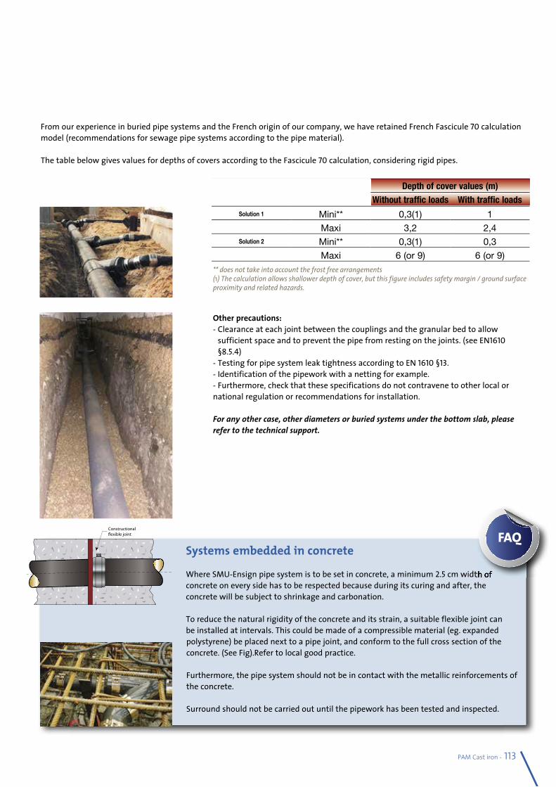
PAM Cast iron - 113
Other precautions:- Clearance at each joint between the couplings and the granular bed to allow
sufficient space and to prevent the pipe from resting on the joints. (see EN1610 §8.5.4)
- Testing for pipe system leak tightness according to EN 1610 §13.- Identification of the pipework with a netting for example.- Furthermore, check that these specifications do not contravene to other local or national regulation or recommendations for installation.
For any other case, other diameters or buried systems under the bottom slab, please refer to the technical support.
Depth of cover values (m)Without traffic loads With traffic loads
Solution 1 Mini** 0,3(1) 1
Maxi 3,2 2,4Solution 2 Mini** 0,3(1) 0,3
Maxi 6 (or 9) 6 (or 9)
From our experience in buried pipe systems and the French origin of our company, we have retained French Fascicule 70 calculation model (recommendations for sewage pipe systems according to the pipe material).
The table below gives values for depths of covers according to the Fascicule 70 calculation, considering rigid pipes.
** does not take into account the frost free arrangements(1) The calculation allows shallower depth of cover, but this figure includes safety margin / ground surface proximity and related hazards.
Systems embedded in concrete
Where SMU-Ensign pipe system is to be set in concrete, a minimum 2.5 cm width of concrete on every side has to be respected because during its curing and after, the concrete will be subject to shrinkage and carbonation.
To reduce the natural rigidity of the concrete and its strain, a suitable flexible joint can be installed at intervals. This could be made of a compressible material (eg. expanded polystyrene) be placed next to a pipe joint, and conform to the full cross section of the concrete. (See Fig).Refer to local good practice.
Furthermore, the pipe system should not be in contact with the metallic reinforcements of the concrete. Surround should not be carried out until the pipework has been tested and inspected.
cm width of
FAQ
�
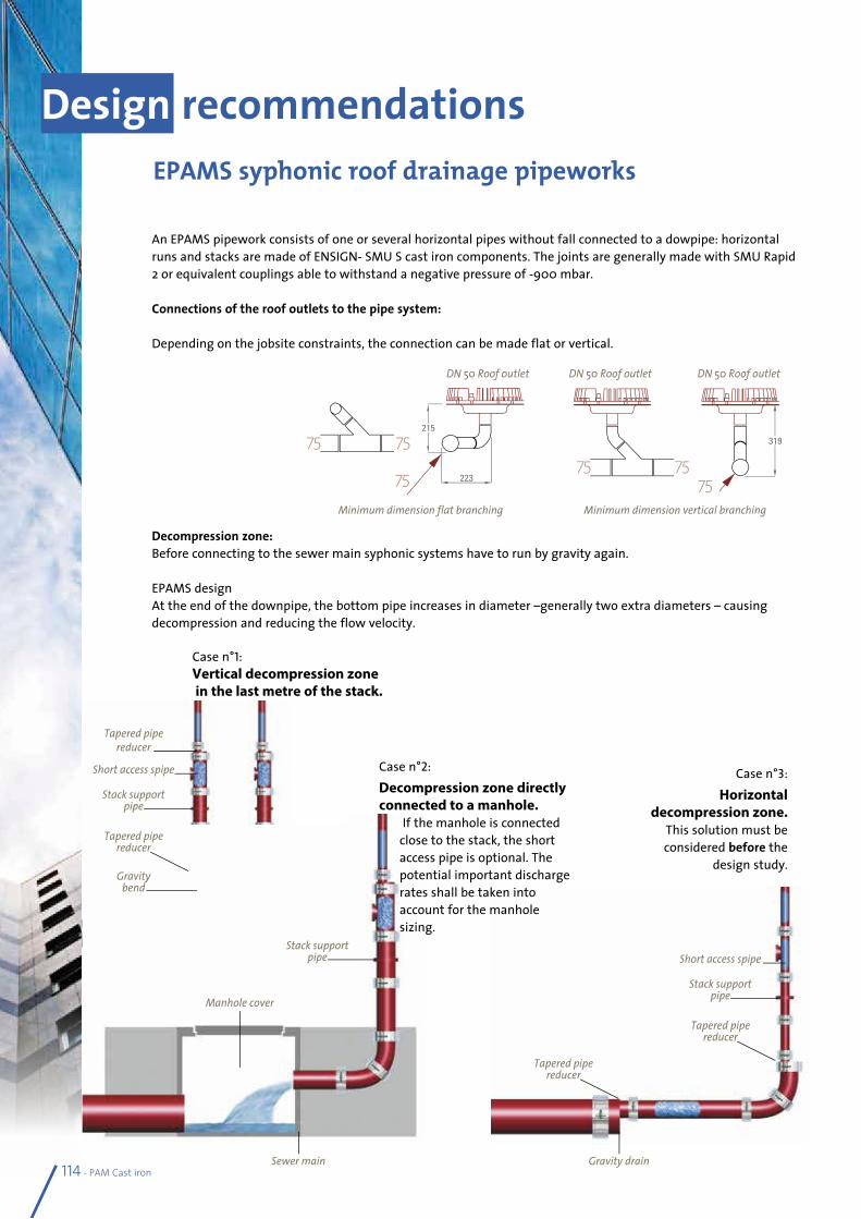
Design recommendations
114 - PAM Cast iron
An EPAMS pipework consists of one or several horizontal pipes without fall connected to a dowpipe: horizontal runs and stacks are made of ENSIGN- SMU S cast iron components. The joints are generally made with SMU Rapid 2 or equivalent couplings able to withstand a negative pressure of -900 mbar.
Connections of the roof outlets to the pipe system:
Depending on the jobsite constraints, the connection can be made flat or vertical.
Decompression zone:Before connecting to the sewer main syphonic systems have to run by gravity again.
EPAMS designAt the end of the downpipe, the bottom pipe increases in diameter –generally two extra diameters – causing decompression and reducing the flow velocity.
EPAMS syphonic roof drainage pipeworks
Minimum dimension flat branching Minimum dimension vertical branching
DN 50 Roof outlet DN 50 Roof outlet DN 50 Roof outlet
Case n°1:Vertical decompression zone in the last metre of the stack.
Case n°2:Decompression zone directly connected to a manhole.
If the manhole is connected close to the stack, the short access pipe is optional. The potential important discharge rates shall be taken into account for the manhole sizing.
Case n°3:Horizontal
decompression zone. This solution must be considered before the
design study.
Tapered pipe reducer
Short access spipe
Stack support pipe
Tapered pipe reducer
Gravity bend
Stack support pipe
Manhole cover
Short access spipe
Stack support pipe
Tapered pipe reducer
Tapered pipe reducer
Sewer main Gravity drain
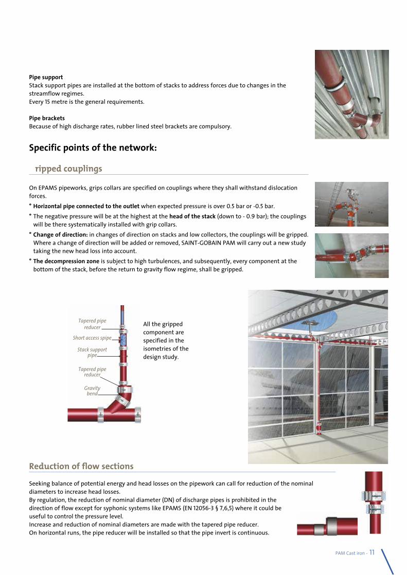
PAM Cast iron - 115
Pipe supportStack support pipes are installed at the bottom of stacks to address forces due to changes in the streamflow regimes.Every 15 metre is the general requirements.
Pipe bracketsBecause of high discharge rates, rubber lined steel brackets are compulsory.
Specific points of the network:
Gripped couplings
On EPAMS pipeworks, grips collars are specified on couplings where they shall withstand dislocation forces.• Horizontal pipe connected to the outlet when expected pressure is over 0.5 bar or -0.5 bar.• The negative pressure will be at the highest at the head of the stack (down to - 0.9 bar); the couplings
will be there systematically installed with grip collars.• Change of direction: in changes of direction on stacks and low collectors, the couplings will be gripped.
Where a change of direction will be added or removed, SAINT-GOBAIN PAM will carry out a new study taking the new head loss into account.
• The decompression zone is subject to high turbulences, and subsequently, every component at the bottom of the stack, before the return to gravity flow regime, shall be gripped.
Reduction of flow sections
Seeking balance of potential energy and head losses on the pipework can call for reduction of the nominal diameters to increase head losses.By regulation, the reduction of nominal diameter (DN) of discharge pipes is prohibited in the direction of flow except for syphonic systems like EPAMS (EN 12056-3 § 7,6,5) where it could be useful to control the pressure level.Increase and reduction of nominal diameters are made with the tapered pipe reducer. On horizontal runs, the pipe reducer will be installed so that the pipe invert is continuous.
Tapered pipe reducer
Short access spipe
Stack support pipe
Tapered pipe reducer
Gravity bend
All the gripped component are specified in the isometries of the design study.
Standards specificationsEN 877:1999 + Amendment / A1: 2006 + Corrigendum / AC: 2008
Cast iron pipes and fittings, their joints and accessories for the evacuation of water from buildings – Requirements, test methods and quality assurance.
Scope:This European Product Standard applies to cast iron pipework elements used for the construction, normally as gravity pipe systems, of discharge systems for buildings and of drains. The range of nominal diameters extends from DN40 to DN600 inclusive. This standard specifies the requirements for the materials, dimensions and toler-ances, mechanical properties, appearance and standard coatings for cast iron pipes, fittings and accessories. It also indicates performance specifications for all components, including joints. It covers, above ground soil, waste, rain-water and buried systems and performance requirements in these applications.
The concerned ranges:PAM-SMU S and Plus, PAM-ENSIGN S and Plus: DN 40 to 600Rainwater range: DN 75 to 150Socket pipe system SME: DN 50 to 150
The EEZI-FIT socket fittings have been included in Kitemark certificate KM51733 for sanitary gravity applications and 0.5 bar (accidental static water pressure) performance: DN 100 and 150.
Definitions:Discharge system for buildings: system of pipes, fittings, accessories and joints used to collect and drain waste water and rainwater from a building; it comprises discharge pipes, ventilation stacks and rainwater pipes, installed within the limits of a building or attached to the building.
Drain: system of pipes, fittings, accessories and joints installed outside the limits of a building in order to connect the discharge system of this building to a soil and drain or a septic tank.
Sewer: system of pipes designed to collect waste water and rainwater from buildings and surface water and to convey them to the point of disposal or treatment.
Requirements:Adhesion see 4.6Hot water resistance: 24 H at 95°C and thermal cycles (1500 cycles of 1min between 15 and 93°C)Salt spray resistance: 350 h Chemical resistance: 2 >pH > 12 at 23°CTo test the chemical resistance of cast iron products standard EN 877 defines that product samples shall be immersed - for 30 days and held at (23 + 3)°C, the pH being constantly monitored - in the following test liquids:- a solution of sulfuric acid at pH 2, for the first sample;- a solution of sodium hydroxide at pH 12, for the second sample.- a solution of waste water at pH 7 for the third sample.
Dimensions - External diameter (DE) see 4.2.2Coatings for pipes and fittings: general see 4.6Specific requirements for coatings for buried systems and rainwater systems installed outside buildings are given in 4.8.3 and 4.9.2 respectively.
Water tightness Joints water tightness – Performance requirements see 4.7.5Reaction to fire see EN 877:1999/A1:2006/AC -4.6.3 External coatings and 5.7.3.3Noise protection see EN 877:1999/A1 - 4.1.4
116 - PAM Cast iron
CE Marking (see Section 1 p 21)
To allow free circulation of industrial products within the European Union, while guaranteeing the safety of European consumers and users of the products, construction products must meet essential requirements covering public health, safety and consumer protection.Based on EN 877, CE marking became mandatory on cast iron wastewater products leaving the European factory, from 2009 September the 1st.
Do not hesitate to compare the reaction to fire classifications of the materials you specify.Remember that CE marking is not a Quality mark or label. Its scope is limited to health and operation safety. It is intend-ed mainly for the authorities in charge of market control.
Product standards and Quality marksStandard EN 877, which defines the requirements for cast iron wastewater pipe systems, is a self-declared standard. This means that the manufacturer is allowed to self declare that his product complies with this standard except for reaction to fire classification of the range which requires an initial type test by a notified test laboratory.
Quality Marks, proof of conformity with EN 877
Voluntary Quality marks aim at fitness for purpose. They add value to the product in terms of customer-supplier relationships.
Only compliance with EN 877 that is validated by a third party for all criteria, and periodically tested, can guarantee the performance of the systems you specify.Look for cast iron products fully complying with EN 877, bearing a quality mark, such as a Kitemark, NF or Watermark for example, being delivered by an accredited certification body.
BS EN 877:1999 Kitemark KM51733Ensign (S and Plus) is the only cast iron system to be tested and awarded Kitemark approval to the product standard in the UK.Ensign EEZI-FIT has been included in the Kitemark certificate KM51733 for sanitary gravity applications and 0.5 bar (accidental static water pressure) performance.
NF EN 877:1999 NF
SMU S and Plus ranges, SME
EN 12056
Gravity drainage systems inside buildings
It covers waste water drainage systems which operate under gravity. It is applicable for drainage systems inside dwellings, commer-cial, institutional and industrial buildings and sets out principles to be followed for both layout and calculation. It makes limited pro-vision for drainage systems conveying trade effluent and also makes limited provision for fluids removed by pumps.
Differences in plumbing within Europe have led to a variety of systems being developed. Some of the major systems in use are described in this standard.
Part 1: General and performance requirements.Part 2: Sanitary pipework, layout and calculation.Part 3: Roof drainage, layout and calculation.Part 4: Wastewater lifting plants - Layout and calculation.Part 5: Installation and testing, instructions for operation, maintenance and use.
PAM Cast iron - 117
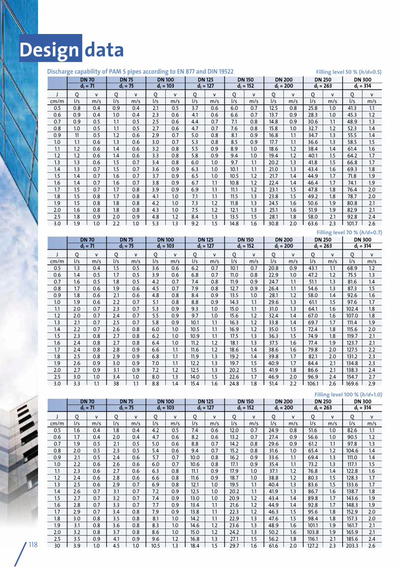
DN 70 DN 75 DN 100 DN 125 DN 150 DN 200 DN 250 DN 300 di = 71 di = 75 di = 103 di = 127 di = 152 di = 200 di = 263 di = 314
J Q v Q v Q v Q v Q v Q v Q v Q v cm/m l/s m/s l/s m/s l/s m/s l/s m/s l/s m/s l/s m/s l/s m/s l/s m/s 0.5 0.8 0.4 0.9 0.4 2.1 0.5 3.7 0.6 6.0 0.7 12.5 0.8 25.8 1.0 41.3 1.1 0.6 0.9 0.4 1.0 0.4 2.3 0.6 4.1 0.6 6.6 0.7 13.7 0.9 28.3 1.0 45.3 1.2 0.7 0.9 0.5 1.1 0.5 2.5 0.6 4.4 0.7 7.1 0.8 14.8 0.9 30.6 1.1 48.9 1.3 0.8 1.0 0.5 1.1 0.5 2.7 0.6 4.7 0.7 7.6 0.8 15.8 1.0 32.7 1.2 52.3 1.4 0.9 11 0.5 1.2 0.6 2.9 0.7 5.0 0.8 8.1 0.9 16.8 1.1 34.7 1.3 55.5 1.4 1.0 1.1 0.6 1.3 0.6 3.0 0.7 5.3 0.8 8.5 0.9 17.7 1.1 36.6 1.3 58.5 1.5 1.1 1.2 0.6 1.4 0.6 3.2 0.8 5.5 0.9 8.9 1.0 18.6 1.2 38.4 1.4 61.4 1.6 1.2 1.2 0.6 1.4 0.6 3.3 0.8 5.8 0.9 9.4 1.0 19.4 1.2 40.1 1.5 64.2 1.7 1.3 1.3 0.6 1.5 0.7 3.4 0.8 6.0 1.0 9.7 1.1 20.2 1.3 41.8 1.5 66.8 1.7 1.4 1.3 0.7 1.5 0.7 3.6 0.9 6.3 1.0 10.1 1.1 21.0 1.3 43.4 1.6 69.3 1.8 1.5 1.4 0.7 1.6 0.7 3.7 0.9 6.5 1.0 10.5 1.2 21.7 1.4 44.9 1.7 71.8 1.9 1.6 1.4 0.7 1.6 0.7 3.8 0.9 6.7 1.1 10.8 1.2 22.4 1.4 46.4 1.7 74.1 1.9 1.7 1.5 0.7 1.7 0.8 3.9 0.9 6.9 1.1 11.1 1.2 23.1 1.5 47.8 1.8 76.4 2.0 1.8 1.5 0.8 1.7 0.8 4.1 1.0 7.1 1.1 11.5 1.3 23.8 1.5 49.2 1.8 78.7 2.0 1.9 1.5 0.8 1.8 0.8 4.2 1.0 7.3 1.2 11.8 1.3 24.5 1.6 50.6 1.9 80.8 2.1 2.0 1.6 0.8 1.8 0.8 4.3 1.0 7.5 1.2 12.1 1.3 25.1 1.6 51.9 1.9 82.9 2.1 2.5 1.8 0.9 2.0 0.9 4.8 1.2 8.4 1.3 13.5 1.5 28.1 1.8 58.0 2.1 92.8 2.4 3.0 1.9 1.0 2.2 1.0 5.3 1.3 9.2 1.5 14.8 1.6 30.8 2.0 63.6 2.3 101.7 2.6
Filling level 50 % (h/d=0.5)
J Q v Q v Q v Q v Q v Q v Q v Q v cm/m l/s m/s l/s m/s l/s m/s l/s m/s l/s m/s l/s m/s l/s m/s l/s m/s 0.5 1.3 0.4 1.5 0.5 3.6 0.6 6.2 0.7 10.1 0.7 20.8 0.9 43.1 1.1 68.9 1.2 0.6 1.4 0.5 1.7 0.5 3.9 0.6 6.8 0.7 11.0 0.8 22.9 1.0 47.2 1.2 75.5 1.3 0.7 1.6 0.5 1.8 0.5 4.2 0.7 7.4 0.8 11.9 0.9 24.7 1.1 51.1 1.3 81.6 1.4 0.8 1.7 0.6 1.9 0.6 4.5 0.7 7.9 0.8 12.7 0.9 26.4 1.1 54.6 1.3 87.3 1.5 0.9 1.8 0.6 2.1 0.6 4.8 0.8 8.4 0.9 13.5 1.0 28.1 1.2 58.0 1.4 92.6 1.6 1.0 1.9 0.6 2.2 0.7 5.1 0.8 8.8 0.9 14.3 1.1 29.6 1.3 61.1 1.5 97.6 1.7 1.1 2.0 0.7 2.3 0.7 5.3 0.9 9.3 1.0 15.0 1.1 31.0 1.3 64.1 1.6 102.4 1.8 1.2 2.0 0.7 2.4 0.7 5.5 0.9 9.7 1.0 15.6 1.2 32.4 1.4 67.0 1.6 107.0 1.8 1.3 2.1 0.7 2.5 0.7 5.8 0.9 10.1 1.1 16.3 1.2 33.8 1.4 69.7 1.7 111.4 1.9 1.4 2.2 0.7 2.6 0.8 6.0 1.0 10.5 1.1 16.9 1.2 35.0 1.5 72.4 1.8 115.6 2.0 1.5 2.3 0.8 2.7 0.8 6.2 1.0 10.9 1.1 17.5 1.3 36.3 1.5 74.9 1.8 119.7 2.1 1.6 2.4 0.8 2.7 0.8 6.4 1.0 11.2 1.2 18.1 1.3 37.5 1.6 77.4 1.9 123.7 2.1 1.7 2.4 0.8 2.8 0.9 6.6 1.1 11.6 1.2 18.6 1.4 38.6 1.6 79.8 2.0 127.5 2.2 1.8 2.5 0.8 2.9 0.9 6.8 1.1 11.9 1.3 19.2 1.4 39.8 1.7 82.1 2.0 131.2 2.3 1.9 2.6 0.9 3.0 0.9 7.0 1.1 12.2 1.3 19.7 1.5 40.9 1.7 84.4 2.1 134.8 2.3 2.0 2.7 0.9 3.1 0.9 7.2 1.2 12.5 1.3 20.2 1.5 41.9 1.8 86.6 2.1 138.3 2.4 2.5 3.0 1.0 3.4 1.0 8.0 1.3 14.0 1.5 22.6 1.7 46.9 2.0 96.9 2.4 154.7 2.7 3.0 3.3 1.1 38 1.1 8.8 1.4 15.4 1.6 24.8 1.8 51.4 2.2 106.1 2.6 169.6 2.9
Filling level 70 % (h/d=0.7)
J Q v Q v Q v Q v Q v Q v Q v Q v cm/m l/s m/s l/s m/s l/s m/s l/s m/s l/s m/s l/s m/s l/s m/s l/s m/s 0.5 1.6 0.4 1.8 0.4 4.2 0.5 7.4 0.6 12.0 0.7 24.9 0.8 51.6 1.0 82.6 1.1 0.6 1.7 0.4 2.0 0.4 4.7 0.6 8.2 0.6 13.2 0.7 27.4 0.9 56.6 1.0 90.5 1.2 0.7 1.9 0.5 2.1 0.5 5.0 0.6 8.8 0.7 14.2 0.8 29.6 0.9 61.2 1.1 97.8 1.3 0.8 2.0 0.5 2.3 0.5 5.4 0.6 9.4 0.7 15.2 0.8 31.6 1.0 65.4 1.2 104.6 1.4 0.9 2.1 0.5 2.4 0.6 5.7 0.7 10.0 0.8 16.2 0.9 33.6 1.1 69.4 1.3 111.0 1.4 1.0 2.2 0.6 2.6 0.6 6.0 0.7 10.6 0.8 17.1 0.9 35.4 1.1 73.2 1.3 117.1 1.5 1.1 2.3 0.6 2.7 0.6 6.3 0.8 11.1 0.9 17.9 1.0 37.1 1.2 76.8 1.4 122.8 1.6 1.2 2.4 0.6 2.8 0.6 6.6 0.8 11.6 0.9 18.7 1.0 38.8 1.2 80.3 1.5 128.3 1.7 1.3 2.5 0.6 2.9 0.7 6.9 0.8 12.1 1.0 19.5 1.1 40.4 1.3 83.6 1.5 133.6 1.7 1.4 2.6 0.7 3.1 0.7 7.2 0.9 12.5 1.0 20.2 1.1 41.9 1.3 86.7 1.6 138.7 1.8 1.5 2.7 0.7 3.2 0.7 7.4 0.9 13.0 1.0 20.9 1.2 43.4 1.4 89.8 1.7 143.6 1.9 1.6 2.8 0.7 3.3 0.7 7.7 0.9 13.4 1.1 21.6 1.2 44.9 1.4 92.8 1.7 148.3 1.9 1.7 2.9 0.7 3.4 0.8 7.9 0.9 13.8 1.1 22.3 1.2 46.3 1.5 95.6 1.8 152.9 2.0 1.8 3.0 0.8 3.5 0.8 8.1 1.0 14.2 1.1 22.9 1.3 47.6 1.5 98.4 1.8 157.3 2.0 1.9 3.1 0.8 3.6 0.8 8.3 1.0 14.6 1.2 23.6 1.3 48.9 1.6 101.1 1.9 161.7 2.1 2.0 3.2 0.8 3.7 0.8 8.6 1.0 15.0 1.2 24.2 1.3 50.2 1.6 103.8 1.9 165.9 2.1 2.5 3.5 0.9 4.1 0.9 9.6 1.2 16.8 1.3 27.1 1.5 56.2 1.8 116.1 2.1 185.6 2.4 30 3.9 1.0 4.5 1.0 10.5 1.3 18.4 1.5 29.7 1.6 61.6 2.0 127.2 2.3 203.3 2.6
Filling level 100 % (h/d=1.0)
Discharge capability of PAM S pipes according to EN 877 and DIN 19522
Design data
118
DN 70 DN 75 DN 100 DN 125 DN 150 DN 200 DN 250 DN 300 di = 71 di = 75 di = 103 di = 127 di = 152 di = 200 di = 263 di = 314
DN 70 DN 75 DN 100 DN 125 DN 150 DN 200 DN 250 DN 300 di = 71 di = 75 di = 103 di = 127 di = 152 di = 200 di = 263 di = 314
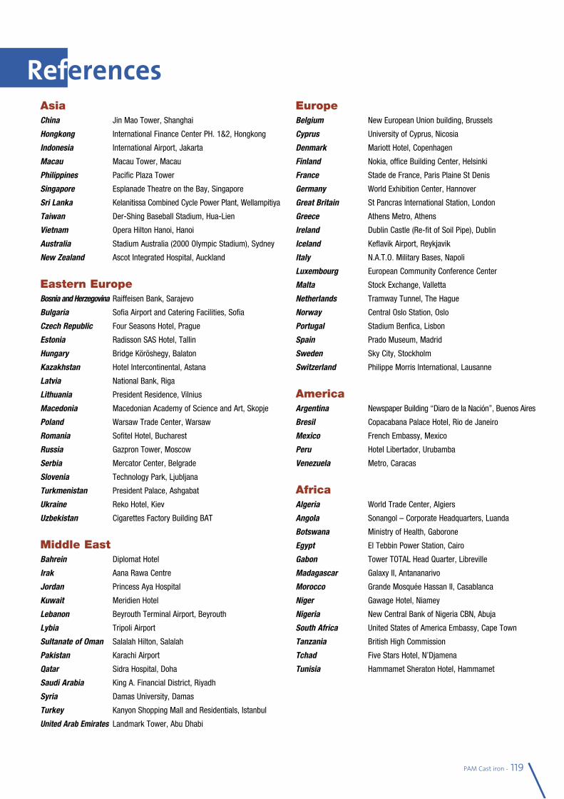
References
PAM Cast iron - 119
AsiaChina Jin Mao Tower, Shanghai
Hongkong International Finance Center PH. 1&2, Hongkong
Indonesia International Airport, Jakarta
Macau Macau Tower, Macau
Philippines Pacific Plaza Tower
Singapore Esplanade Theatre on the Bay, Singapore
Sri Lanka Kelanitissa Combined Cycle Power Plant, Wellampitiya
Taiwan Der-Shing Baseball Stadium, Hua-Lien
Vietnam Opera Hilton Hanoi, Hanoi
Australia Stadium Australia (2000 Olympic Stadium), Sydney
New Zealand Ascot Integrated Hospital, Auckland
Eastern EuropeBosnia and Herzegovina Raiffeisen Bank, Sarajevo
Bulgaria Sofia Airport and Catering Facilities, Sofia
Czech Republic Four Seasons Hotel, Prague
Estonia Radisson SAS Hotel, Tallin
Hungary Bridge Köröshegy, Balaton
Kazakhstan Hotel Intercontinental, Astana
Latvia National Bank, Riga
Lithuania President Residence, Vilnius
Macedonia Macedonian Academy of Science and Art, Skopje
Poland Warsaw Trade Center, Warsaw
Romania Sofitel Hotel, Bucharest
Russia Gazpron Tower, Moscow
Serbia Mercator Center, Belgrade
Slovenia Technology Park, Ljubljana
Turkmenistan President Palace, Ashgabat
Ukraine Reko Hotel, Kiev
Uzbekistan Cigarettes Factory Building BAT
Middle EastBahrein Diplomat Hotel
Irak Aana Rawa Centre
Jordan Princess Aya Hospital
Kuwait Meridien Hotel
Lebanon Beyrouth Terminal Airport, Beyrouth
Lybia Tripoli Airport
Sultanate of Oman Salalah Hilton, Salalah
Pakistan Karachi Airport
Qatar Sidra Hospital, Doha
Saudi Arabia King A. Financial District, Riyadh
Syria Damas University, Damas
Turkey Kanyon Shopping Mall and Residentials, Istanbul
United Arab Emirates Landmark Tower, Abu Dhabi
EuropeBelgium New European Union building, Brussels
Cyprus University of Cyprus, Nicosia
Denmark Mariott Hotel, Copenhagen
Finland Nokia, office Building Center, Helsinki
France Stade de France, Paris Plaine St Denis
Germany World Exhibition Center, Hannover
Great Britain St Pancras International Station, London
Greece Athens Metro, Athens
Ireland Dublin Castle (Re-fit of Soil Pipe), Dublin
Iceland Keflavik Airport, Reykjavik
Italy N.A.T.O. Military Bases, Napoli
Luxembourg European Community Conference Center
Malta Stock Exchange, Valletta
Netherlands Tramway Tunnel, The Hague
Norway Central Oslo Station, Oslo
Portugal Stadium Benfica, Lisbon
Spain Prado Museum, Madrid
Sweden Sky City, Stockholm
Switzerland Philippe Morris International, Lausanne
AmericaArgentina Newspaper Building “Diaro de la Nación”, Buenos Aires
Bresil Copacabana Palace Hotel, Rio de Janeiro
Mexico French Embassy, Mexico
Peru Hotel Libertador, Urubamba
Venezuela Metro, Caracas
AfricaAlgeria World Trade Center, Algiers
Angola Sonangol – Corporate Headquarters, Luanda
Botswana Ministry of Health, Gaborone
Egypt El Tebbin Power Station, Cairo
Gabon Tower TOTAL Head Quarter, Libreville
Madagascar Galaxy II, Antananarivo
Morocco Grande Mosquée Hassan II, Casablanca
Niger Gawage Hotel, Niamey
Nigeria New Central Bank of Nigeria CBN, Abuja
South Africa United States of America Embassy, Cape Town
Tanzania British High Commission
Tchad Five Stars Hotel, N’Djamena
Tunisia Hammamet Sheraton Hotel, Hammamet
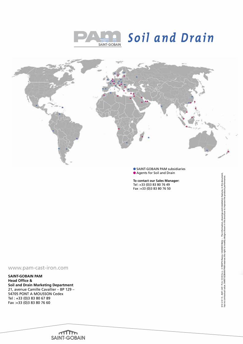
l SAINT-GOBAIN PAM subsidiariesl Agents for Soil and Drain
To contact our Sales Manager: Tel :+33 (0)3 83 80 76 49 Fax :+33 (0)3 83 80 76 50
S o i l a n d D r a i n
www.pam-cast-iron.com
SAINT-GOBAIN PAMHead Office &Soil and Drain Marketing Department 21, avenue Camille Cavallier – BP 129 – 54705 PONT A MOUSSON CedexTel : +33 (0)3 83 80 67 89 Fax :+33 (0)3 83 80 76 60
0 9
/ 2 0
1 5
– B
AT-
CA
T- 7
5 A
- 5 0
0 0
e x
– S
YN
OP
6 N
ancy
/ A
VA
NCE
Met
z –
The
info
rmat
ion,
dra
win
gs a
nd in
stal
lati
on f
eatu
res,
in t
his
docu
men
t,
has
no c
ontr
actu
al v
alue
. SA
INT-
GO
BAIN
PA
M r
eser
ves
the
righ
t to
mod
ify
desi
gns
show
n in
thi
s br
ochu
re t
o im
prov
e th
e pr
oduc
ts p
erfo
rman
ce.