Smt. S. R. PATEL ENGINEERING COLLEGE Dabhi, unjha …mechanical.srpec.org.in/Labs/LEXEQ/L2.pdf ·...
59
Smt. S. R. PATEL ENGINEERING COLLEGE Dabhi, unjha pin- 384 170 Department of MECHANICAL engineering Subject : Material Science & Metallurgy Subject code: 131904 EXPERIMENTS IN MATERIAL SCIENCE & METALLURGY
Transcript of Smt. S. R. PATEL ENGINEERING COLLEGE Dabhi, unjha …mechanical.srpec.org.in/Labs/LEXEQ/L2.pdf ·...
Smt. S. R. PATEL ENGINEERING COLLEGE
Dabhi, unjha
pin- 384 170
Department of MECHANICAL engineering
Subject : Material Science & Metallurgy
Subject code: 131904
EXP
ERIM
ENTS
IN M
ATE
RIA
L SC
IEN
CE
& M
ETA
LLU
RG
Y

Experiments in Material Science & Metallurgy: Semester III
Mechanical Engineering, S.R. Patel Engg College, Dabhi
INDEX
Sr.
No. Experiment Page No. Date Sign
1 Study of phase diagrams for structure-properties
correlation
2 Study of - iron carbide equilibrium diagram.
3 Study of optical (metallurgical) microscope.
4 Preparation of specimen for microscopic examination.
5 Mounting of Specimen
6 Microstructural observation of ferrous materials.
7 Effect of quenching media on hardening of steels.
8 Determination of hardenability of steels.
9 Determine the effect of section size on hardness of the
material developed during quenching.
10 Detection of flaws in materials using ultrasonic flaw
detector.
1 1 Detection of flaws in materials through dye-penetrates Test
magnetic particle inspection methods.
Experiments in Material Science & Metallurgy: Semester III
Mechanical Engineering, S.R. Patel Engg College, Dabhi Page 1
Study of phase diagrams for structure-properties correlation
Experiment No:-1 Date:
Objective: To study the phase diagram for structure-properties correlation.
Theory:
Phase diagrams are equilibrium diagrams or constitutional diagrams which gives sufficient
information concerning the phase changes in many heterogeneous systems such as alloy
systems. Phase diagrams are graphical representation showing phase relationship that exists
in an alloy as it slowly cools from molten state. These phase diagrams show the limits of
composition and temperature within which various constituents and phases of any system are
stable. One of the important applications of phase diagram is the study of alloy which exists
in different equilibrium composition at different temperature. Knowledge of phase diagram is
very helpful in controlling and understanding heat treatment processes. With the help of
phase diagram, it is possible to estimate the temperatures at which either melting or phase
transformation starts and/or completes.
Some of important characteristics of phase diagram are given below:
1. It is a kind of map or graph that gives the relationship between phases in equilibrium in a
system as a function of temperature, pressure, or composition.
2. One can know the melting, solidifying and allotropic change temperature from the
diagram.
3. Solubility of alloying element (carbon) at different temperature and in various phases can
be known.
4. It gives rough idea about post-solidification structure and properties, with varying carbon
content.
5. It is very useful in revealing the path through which changes are likely to take place.
6. It is also helpful for the study of growth and doping of single crystal.
7. It is very useful in heat treatment processes.
8. An equilibrium diagram or phase diagram of an alloy system shows the limits of
composition and temperature within which various constituents or phase of an alloy
system exist.
9. Through phase diagrams, various purification and separation processes can be understood
deeply. For the example the solidification and phase separation of metal alloy can be done
effectively through phase diagram studies.
TYPES OF PHASE DIAGRAM:
1. According to number of components present in alloy system:
i) Single components phase diagrams
ii) Binary components phase diagrams
iii) Ternary components phase diagrams
Experiments in Material Science & Metallurgy: Semester III
Mechanical Engineering, S.R. Patel Engg College, Dabhi Page 2
In single components system or phase diagram there is only a single component. A good
example of this is the water system where the single components water exists in three phase
such as ice, water and water vapor based on the variables or degree of freedom (F) such as
temperature and pressure are the variable and composition is not a variable. The phase rule for single components system is given by F=C-P+2.
Out of the three variables (T, P and composition) or degree of freedom the phase diagrams of
metals are drawn at atmospheric pressure (i.e. pressure changes have negligible effect on
solid or liquid metal. Pressure has effect only on gaseous Metal i.e. above boiling point
showing variation in corn position and tempera Lire only. Hence the phase rule F= C-P+2 can
be simplified here with the reduced phase rule F= C-P+ 1.
2. According to the solubility characteristics of two metals:
ISOMORPHOUS SYSTEM:
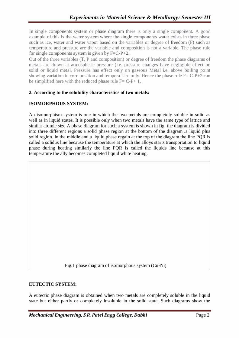
An isomorphism system is one in which the two metals are completely soluble in solid as
well as in liquid states. It is possible only when two metals have the same type of lattice and
similar atomic size A phase diagram for such a system is shown in fig. the diagram is divided
into three different regions a solid phase region at the bottom of the diagram .a liquid plus
solid region in the middle and a liquid phase regain at the top of the diagram the line PQR is
called a solidus line because the temperature at which the alloys starts transportation to liquid
phase during heating similarly the line PQR is called the liquids line because at this
temperature the ally becomes completed liquid white heating.
Fig.1 phase diagram of isomorphous system (Cu-Ni)
EUTECTIC SYSTEM:
A eutectic phase diagram is obtained when two metals are completely soluble in the liquid
state but either partly or completely insoluble in the solid state. Such diagrams show the

Experiments in Material Science & Metallurgy: Semester III
Mechanical Engineering, S.R. Patel Engg College, Dabhi Page 3
existence of a eutectic reactions in which a liquid phase decomposes into different solids. A
eutectic reaction can be represented by, Liquid L — > Solid a + Solid B
Fig.2 : Phase diagram of eutectic system (Cd-Bi)
PERITECTIC SYETEMS:
When the melting points of two metals differ considerable another type of reaction occurs, in
which one liquid and one solid combine to form a new solid. Such a reaction is called a
peritectic reaction and it is expressed as. Liquid + Solid A —> Solid B
Fig.3 : Phase diagram of peritectic system (Ag-Pt)
Experiments in Material Science & Metallurgy: Semester III
Mechanical Engineering, S.R. Patel Engg College, Dabhi Page 4
The new soil formed is usually an inter-metallic compound but in some cases it may be a
terminal soil solution. The phase diagram showing the occurrence of peritectic reaction is
shown in fig. the peritectic reaction occur at a constant temperature. Some of the typical alloy
systems which show the reaction are Fe-c, Ag-pt. etc.
MONOTECTIVE SYSTEM:
In all the types discussed so far, it was assumed that there was complete solubility in the
liquid state bit it is quit possible that over a certain composition range two liquid solution
formed are not soluble in each other. The two liquids show a miscibility gap over a certain
composition range. Such a situation arises in monotectic systems. Where one liquid
decomposes into another liquid and one solid. Such a reaction is called a monotectic reaction
and can be expressed as follows:
Liquid A→ Liquid B+ Solid
The phase diagram showing the occurrence of a monotectic reaction is shown in fig. some
typical alloys systems which show monotectic reaction are Cu-Pb, Cu-Cr, Al-Pb, Zn-Pb.
EUTECTOUID SYSTEMS:
In all the previous phase diagram we have considered liquid to solid or solid to liquid
transformation but solid to solid transformations are also common in phase diagrams. One
such transformation is called a eutectic reaction in which one solid decomposes into two
different solids. A eutectic reaction can be expressed as SolidA→ Solid B+ SolidC
Eutectoid transformation takes place at a constant temperature and the product of the
transformation are present as intimate mechanical mixture having a distinct appearance under
the microscope the phase diagram showing the occurrence of a eutectoid reaction is shown in
the fig. some alloy systems which show eutectoid reaction are Fe-C, Cu-Zn,Al-Mn, Cu-Sn
etc.
The important applications of phase diagram can be as follows:
1. To select and control heat treatment process parameter, holding temperature, & the holding
time and the various other surface heat treatment process parameters.
2. To produce desired properties in final product to suit the service conditions.
3. To understand the properties of material and contribution towards gaining and inside in to
the controlled microscopic structure
4. To understand the properties of the materials and the contribution towards gaining and
inside in to controlled microstructure.
5. To develop a special grade of ally with optimum combination of properties. Subject to
variation in microstructure.
6. One of the important applications of phase diagram is in zone refinery of materials to
produce ultra clean material (i.e. that is highly level of purity) for various special application
e.g. semi conducting crystals & other high-tech applications.

Experiments in Material Science & Metallurgy: Semester III
Mechanical Engineering, S.R. Patel Engg College, Dabhi Page 5
Reference books:
1. Introduction to Physical Metallurgy - By Sidney H. Avner. Mc-GRAW HILL
International Edition.
2. Heat Treatment (Principles and Techniques) - By T.V. Rajan. CP. Sharma & Ashok
Sharma. Prentice Hall of India Pvt. Ltd.
Quizs:
1. What is a phase diagram? What is its signification'?
2. What is indicated by solidus. liquidus and solvus lines?

Experiments in Material Science & Metallurgy: Semester III
Mechanical Engineering, S.R. Patel Engg College, Dabhi Page 6
3. List out the application of phase diagram.
4.Compare solidification characteristics of a pure metal and of an alloy?

Experiments in Material Science & Metallurgy: Semester III
Mechanical Engineering, S.R. Patel Engg College, Dabhi Page 7
5.What is a eutectic reaction? How docs it differ from eutectoid reach
Date: Sign: Grade:
Experiments in Material Science & Metallurgy: Semester III
Mechanical Engineering, S.R. Patel Engg College, Dabhi Page 8
IRON-CARBIDE EQUILIBRIUM PHASE DIAGRAM
Experiment No: 2 Date:
Objective: to study iron-iron carbide equilibrium phase diagram.
Theory:
Like every metal, iron has its definite melting and solidification temperature. Alloying
elements influence these temperatures. Iron is an allotropic metal, as depending upon
temperature iron can exist in more than one type of lattice structure. The temperature at
which the allotropic changes take place in iron is influenced by alloying elements. The most
important of which is carbon. This inherent alloying element plays important role in
properties of steel and cast iron the fundamental engineering materials.
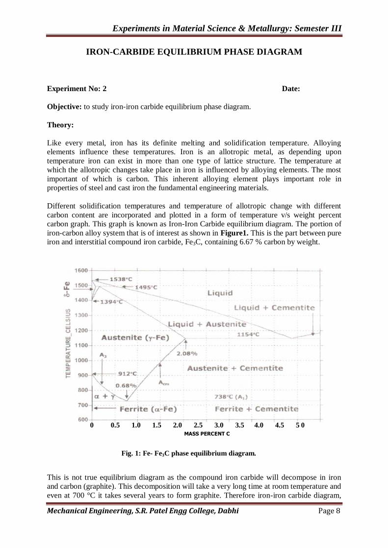
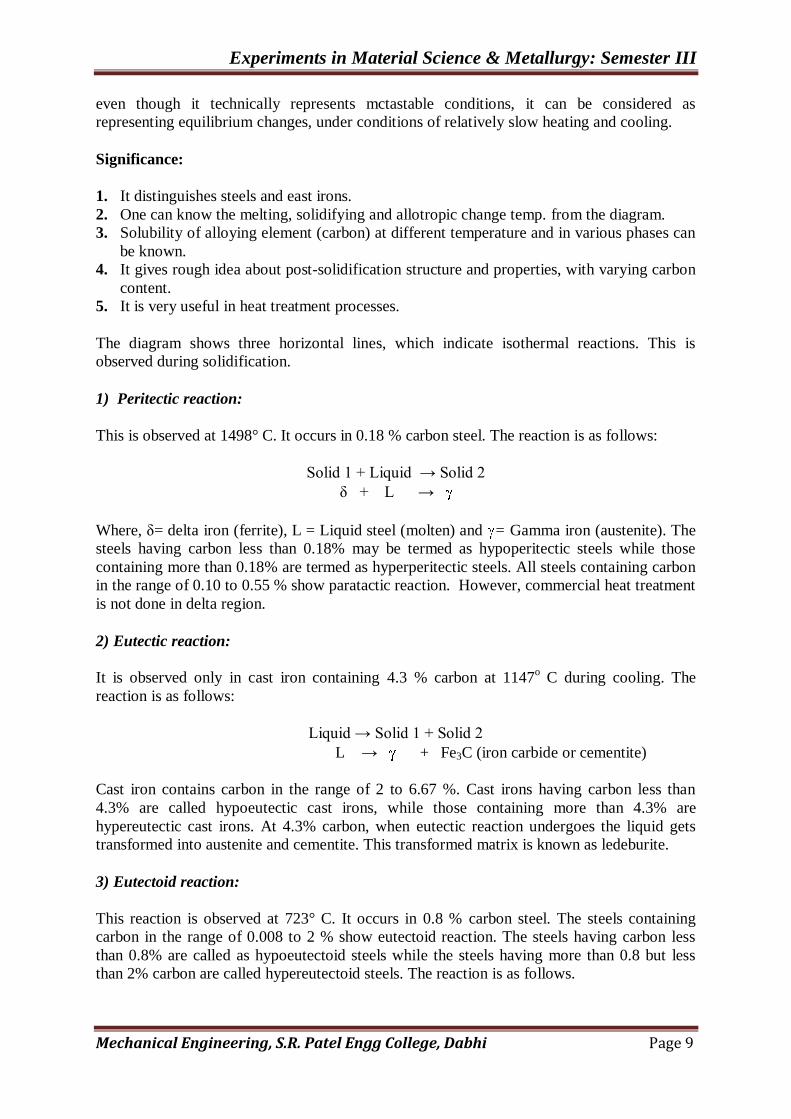
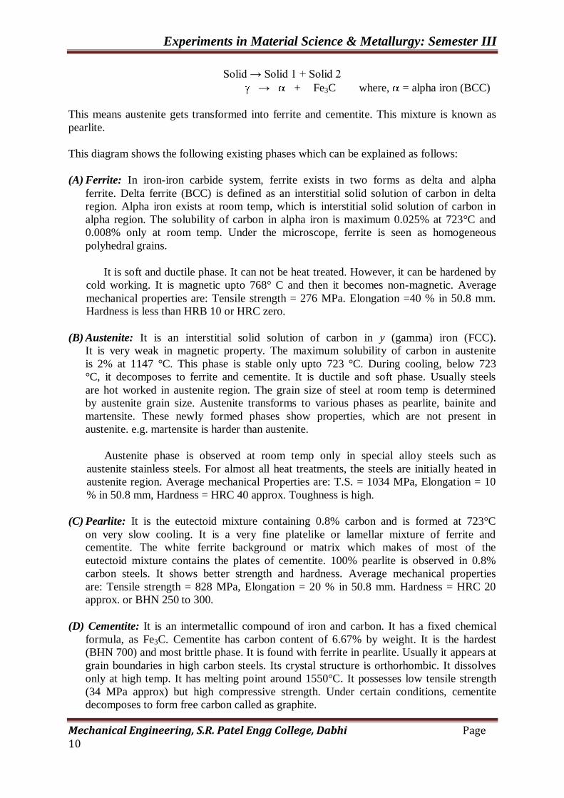
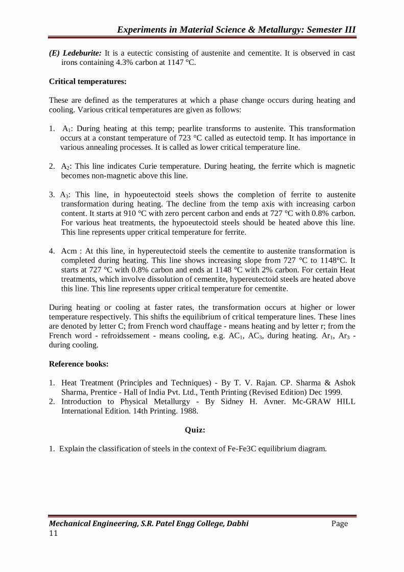
Different solidification temperatures and temperature of allotropic change with different
carbon content are incorporated and plotted in a form of temperature v/s weight percent
carbon graph. This graph is known as Iron-Iron Carbide equilibrium diagram. The portion of
iron-carbon alloy system that is of interest as shown in Figure1. This is the part between pure
iron and interstitial compound iron carbide, Fe3C, containing 6.67 % carbon by weight.
This is not true equilibrium diagram as the compound iron carbide will decompose in iron
and carbon (graphite). This decomposition will take a very long time at room temperature and
even at 700 °C it takes several years to form graphite. Therefore iron-iron carbide diagram,
0 0.5 1.0 1.5 2.0 2.5 3.0 3.5 4.0 4.5 5 0
MASS PERCENT C
Fig. 1: Fe- Fe3C phase equilibrium diagram.
Experiments in Material Science & Metallurgy: Semester III
Mechanical Engineering, S.R. Patel Engg College, Dabhi Page 9
even though it technically represents mctastable conditions, it can be considered as
representing equilibrium changes, under conditions of relatively slow heating and cooling.
Significance:
1. It distinguishes steels and east irons.
2. One can know the melting, solidifying and allotropic change temp. from the diagram.
3. Solubility of alloying element (carbon) at different temperature and in various phases can
be known.
4. It gives rough idea about post-solidification structure and properties, with varying carbon
content.
5. It is very useful in heat treatment processes.
The diagram shows three horizontal lines, which indicate isothermal reactions. This is
observed during solidification.
1) Peritectic reaction:
This is observed at 1498° C. It occurs in 0.18 % carbon steel. The reaction is as follows:
Solid 1 + Liquid → Solid 2
δ + L →
Where, δ= delta iron (ferrite), L = Liquid steel (molten) and = Gamma iron (austenite). The
steels having carbon less than 0.18% may be termed as hypoperitectic steels while those
containing more than 0.18% are termed as hyperperitectic steels. All steels containing carbon
in the range of 0.10 to 0.55 % show paratactic reaction. However, commercial heat treatment
is not done in delta region.
2) Eutectic reaction:
It is observed only in cast iron containing 4.3 % carbon at 1147o C during cooling. The
reaction is as follows:
Liquid → Solid 1 + Solid 2
L → + Fe3C (iron carbide or cementite)
Cast iron contains carbon in the range of 2 to 6.67 %. Cast irons having carbon less than
4.3% are called hypoeutectic cast irons, while those containing more than 4.3% are
hypereutectic cast irons. At 4.3% carbon, when eutectic reaction undergoes the liquid gets
transformed into austenite and cementite. This transformed matrix is known as ledeburite.
3) Eutectoid reaction:
This reaction is observed at 723° C. It occurs in 0.8 % carbon steel. The steels containing
carbon in the range of 0.008 to 2 % show eutectoid reaction. The steels having carbon less
than 0.8% are called as hypoeutectoid steels while the steels having more than 0.8 but less
than 2% carbon are called hypereutectoid steels. The reaction is as follows.
Experiments in Material Science & Metallurgy: Semester III
Mechanical Engineering, S.R. Patel Engg College, Dabhi Page 10
Solid → Solid 1 + Solid 2
→ + Fe3C where, = alpha iron (BCC)
This means austenite gets transformed into ferrite and cementite. This mixture is known as
pearlite.
This diagram shows the following existing phases which can be explained as follows:
(A) Ferrite: In iron-iron carbide system, ferrite exists in two forms as delta and alpha
ferrite. Delta ferrite (BCC) is defined as an interstitial solid solution of carbon in delta
region. Alpha iron exists at room temp, which is interstitial solid solution of carbon in
alpha region. The solubility of carbon in alpha iron is maximum 0.025% at 723°C and
0.008% only at room temp. Under the microscope, ferrite is seen as homogeneous
polyhedral grains.
It is soft and ductile phase. It can not be heat treated. However, it can be hardened by
cold working. It is magnetic upto 768° C and then it becomes non-magnetic. Average
mechanical properties are: Tensile strength = 276 MPa. Elongation =40 % in 50.8 mm.
Hardness is less than HRB 10 or HRC zero.
(B) Austenite: It is an interstitial solid solution of carbon in y (gamma) iron (FCC).
It is very weak in magnetic property. The maximum solubility of carbon in austenite
is 2% at 1147 °C. This phase is stable only upto 723 °C. During cooling, below 723
°C, it decomposes to ferrite and cementite. It is ductile and soft phase. Usually steels
are hot worked in austenite region. The grain size of steel at room temp is determined
by austenite grain size. Austenite transforms to various phases as pearlite, bainite and
martensite. These newly formed phases show properties, which are not present in
austenite. e.g. martensite is harder than austenite.
Austenite phase is observed at room temp only in special alloy steels such as
austenite stainless steels. For almost all heat treatments, the steels are initially heated in
austenite region. Average mechanical Properties are: T.S. = 1034 MPa, Elongation = 10
% in 50.8 mm, Hardness = HRC 40 approx. Toughness is high.
(C) Pearlite: It is the eutectoid mixture containing 0.8% carbon and is formed at 723°C
on very slow cooling. It is a very fine platelike or lamellar mixture of ferrite and
cementite. The white ferrite background or matrix which makes of most of the
eutectoid mixture contains the plates of cementite. 100% pearlite is observed in 0.8%
carbon steels. It shows better strength and hardness. Average mechanical properties
are: Tensile strength = 828 MPa, Elongation = 20 % in 50.8 mm. Hardness = HRC 20
approx. or BHN 250 to 300.
(D) Cementite: It is an intermetallic compound of iron and carbon. It has a fixed chemical
formula, as Fe3C. Cementite has carbon content of 6.67% by weight. It is the hardest
(BHN 700) and most brittle phase. It is found with ferrite in pearlite. Usually it appears at
grain boundaries in high carbon steels. Its crystal structure is orthorhombic. It dissolves
only at high temp. It has melting point around 1550°C. It possesses low tensile strength
(34 MPa approx) but high compressive strength. Under certain conditions, cementite
decomposes to form free carbon called as graphite.
Experiments in Material Science & Metallurgy: Semester III
Mechanical Engineering, S.R. Patel Engg College, Dabhi Page 11
(E) Ledeburite: It is a eutectic consisting of austenite and cementite. It is observed in cast
irons containing 4.3% carbon at 1147 °C.
Critical temperatures:
These are defined as the temperatures at which a phase change occurs during heating and
cooling. Various critical temperatures are given as follows:
1. A1: During heating at this temp; pearlite transforms to austenite. This transformation
occurs at a constant temperature of 723 °C called as eutectoid temp. It has importance in
various annealing processes. It is called as lower critical temperature line.
2. A2: This line indicates Curie temperature. During heating, the ferrite which is magnetic
becomes non-magnetic above this line.
3. A3: This line, in hypoeutectoid steels shows the completion of ferrite to austenite
transformation during heating. The decline from the temp axis with increasing carbon
content. It starts at 910 °C with zero percent carbon and ends at 727 °C with 0.8% carbon.
For various heat treatments, the hypoeutectoid steels should be heated above this line.
This line represents upper critical temperature for ferrite.
4. Acm : At this line, in hypereutectoid steels the cementite to austenite transformation is
completed during heating. This line shows increasing slope from 727 °C to 1148°C. It
starts at 727 °C with 0.8% carbon and ends at 1148 °C with 2% carbon. For certain Heat
treatments, which involve dissolution of cementite, hypereutectoid steels are heated above
this line. This line represents upper critical temperature for cementite.
During heating or cooling at faster rates, the transformation occurs at higher or lower
temperature respectively. This shifts the equilibrium of critical temperature lines. These lines
are denoted by letter C; from French word chauffage - means heating and by letter r; from the
French word - refroidssement - means cooling, e.g. AC1, AC3, during heating. Ar1, Ar3 -
during cooling.
Reference books:
1. Heat Treatment (Principles and Techniques) - By T. V. Rajan. CP. Sharma & Ashok
Sharma, Prentice - Hall of India Pvt. Ltd., Tenth Printing (Revised Edition) Dec 1999.
2. Introduction to Physical Metallurgy - By Sidney H. Avner. Mc-GRAW HILL
International Edition. 14th Printing. 1988.
Quiz:
1. Explain the classification of steels in the context of Fe-Fe3C equilibrium diagram.

Experiments in Material Science & Metallurgy: Semester III
2. The mechanical properties of steels are structure dependent— Comment on it.
3. What are the critical temperatures? Explain their significance.

Experiments in Material Science & Metallurgy: Semester III
4. Draw typical micro-structures of 0.2%, 0.4%, 0.6% and 0.8% carbon steel. Comment
on the amount of phases present.
5. What are the liquidus and solidus curves in an equilibrium diagram?
6. Discuss allotropic change of iron during cooling to room temperature from molten iron.

Experiments in Material Science & Metallurgy: Semester III
7. With respect to iron-iron carbide diagram explain;
A) slow cooling of 0.35 % carbon steel and
B) Slow cooling of 1.5% carbon steel.
Date: Sign: Grade
Experiments in Material Science & Metallurgy: Semester III
OPTICAL MICROSCOPE
Experiment No:-3 Date:
Objective: To study optical (metallurgical) microscope.
Theory:
Microscope is an important tool for a mechanical / metallurgical engineer. Metallurgical
Microscope is very helpful in determining the size, shape and distribution of various
phases, including inclusions in metals. Grain size determination is also made with the
help of metallurgical microscope. All these studies have a great bearing on the
mechanical properties of metals. No structure-property correlation can be made without
the help of metallography.
For study of metallurgical microstructures, microscope is used. Various microscopes used
are as follows:
Optical microscope,
Electron microscope
o Scanning electron microscope.
o Transmission electron microscope etc.
A metallurgical microscope differs from a biological microscope in following respect:
It uses an external sources of light.
Metallurgical samples are opaque to light, and
Reflected light is used in metallurgical microscope.
Working principle:
A horizontal beam of light from a suitable source is diverted downward by a plane glass
reflector through the objective lens on etched surface of specimen. The light gets reflected
back and passed through the objective and then eyepiece. By observing through the
eyepiece, an enlarged image of illuminated area may be studied. An aperture diaphragm
opening should be optimum to observe the structure fully.
Construction:
It consists of (a) main frame (b) eye piece lens (c) objective lens (d) revolving nose piece
for objectives (e) knobs for coarse and fine adjustment (f) light source (g) light intensity
knob (h) specimen stage with x and y direction movement and (i) filters.
All the above parts are fitted on the main frame. The lens from which the microstructure
is observed is called an eyepiece. Objective lens is the lens near the specimen. Revolving
nosepiece consist of objective lens of different magnification. The coarse and fine
adjustment knobs are used to focus the image sharply. The light source provides
illumination. For adjustment of brightness, the light intensity knob is used. The specimen
may be scanned without touching it. by using x and y direction movement knobs. Better
contrast may be obtained by adding or removing some of the filters.
Experiments in Material Science & Metallurgy: Semester III
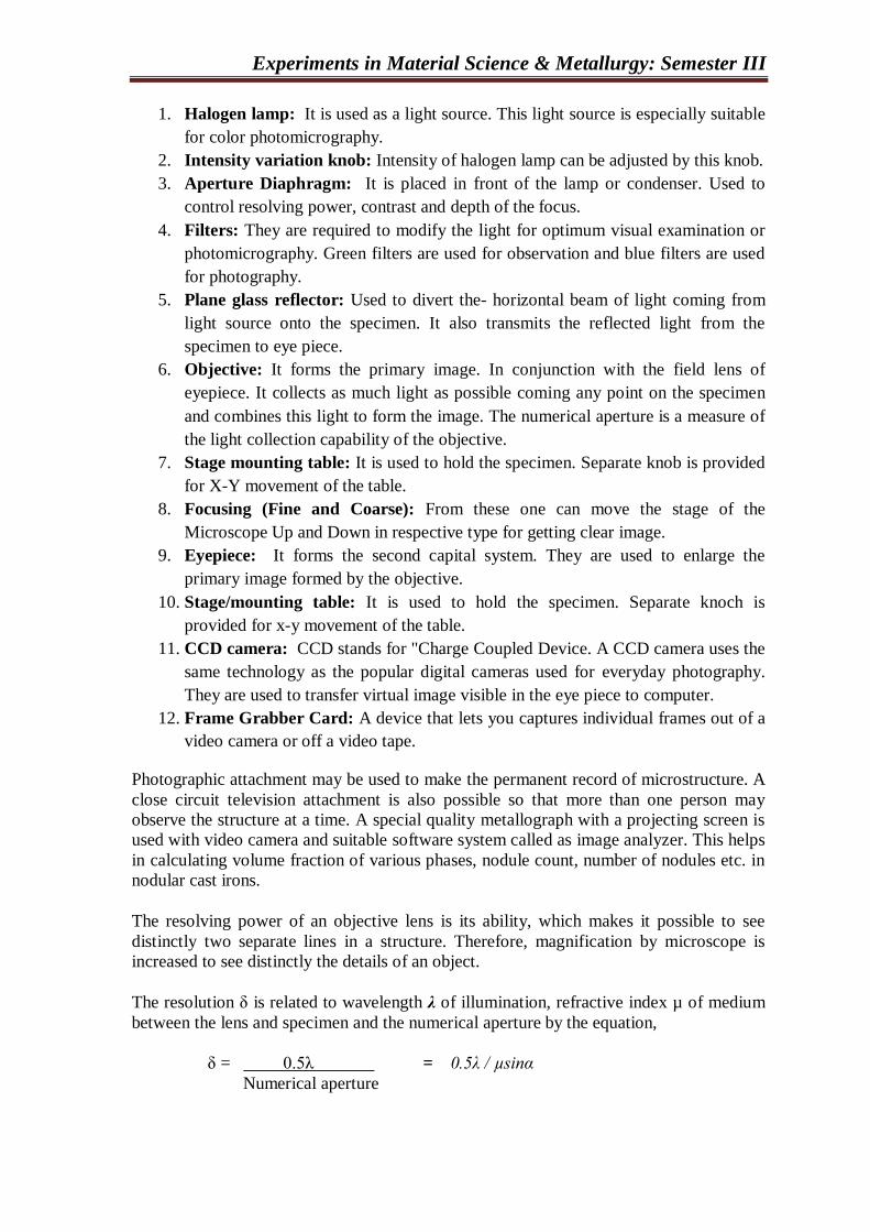
1. Halogen lamp: It is used as a light source. This light source is especially suitable
for color photomicrography.
2. Intensity variation knob: Intensity of halogen lamp can be adjusted by this knob.
3. Aperture Diaphragm: It is placed in front of the lamp or condenser. Used to
control resolving power, contrast and depth of the focus.
4. Filters: They are required to modify the light for optimum visual examination or
photomicrography. Green filters are used for observation and blue filters are used
for photography.
5. Plane glass reflector: Used to divert the- horizontal beam of light coming from
light source onto the specimen. It also transmits the reflected light from the
specimen to eye piece.
6. Objective: It forms the primary image. In conjunction with the field lens of
eyepiece. It collects as much light as possible coming any point on the specimen
and combines this light to form the image. The numerical aperture is a measure of
the light collection capability of the objective.
7. Stage mounting table: It is used to hold the specimen. Separate knob is provided
for X-Y movement of the table.
8. Focusing (Fine and Coarse): From these one can move the stage of the
Microscope Up and Down in respective type for getting clear image.
9. Eyepiece: It forms the second capital system. They are used to enlarge the
primary image formed by the objective.
10. Stage/mounting table: It is used to hold the specimen. Separate knoch is
provided for x-y movement of the table.
11. CCD camera: CCD stands for "Charge Coupled Device. A CCD camera uses the
same technology as the popular digital cameras used for everyday photography.
They are used to transfer virtual image visible in the eye piece to computer.
12. Frame Grabber Card: A device that lets you captures individual frames out of a
video camera or off a video tape.
Photographic attachment may be used to make the permanent record of microstructure. A
close circuit television attachment is also possible so that more than one person may
observe the structure at a time. A special quality metallograph with a projecting screen is
used with video camera and suitable software system called as image analyzer. This helps
in calculating volume fraction of various phases, nodule count, number of nodules etc. in
nodular cast irons.
The resolving power of an objective lens is its ability, which makes it possible to see
distinctly two separate lines in a structure. Therefore, magnification by microscope is
increased to see distinctly the details of an object.
The resolution δ is related to wavelength λ of illumination, refractive index µ of medium
between the lens and specimen and the numerical aperture by the equation,
δ = 0.5λ = 0.5λ / µsinα
Numerical aperture
Experiments in Material Science & Metallurgy: Semester III
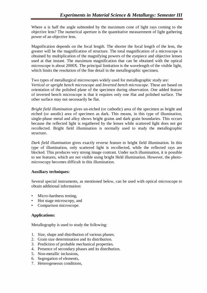
Where α is half the angle subtended by the maximum cone of light rays coming to the
objective lens? The numerical aperture is the quantitative measurement of light gathering
power of an objective lens.
Magnification depends on the focal length. The shorter the focal length of the lens, the
greater will be the magnification of structure. The total magnification of a microscope is
obtained by multiplication of the magnifying powers of the eyepiece and objective lenses
used at that instant. The maximum magnification that can be obtained with the optical
microscope is about 2000X. The principal limitation is the wavelength of the visible light,
which limits the resolution of the fine detail in the metallographic specimen.
Two types of metallurgical microscopes widely used for metallographic study are:
Vertical or upright bench microscope and Inverted bench microscope. These are based on
orientation of the polished plane of the specimen during observation. One added feature
of inverted bench microscope is that it requires only one Hat and polished surface. The
other surface may not necessarily be flat.
Bright field illumination gives un-etched (or cathodic) area of the specimen as bright and
etched (or anodic) area of specimen as dark. This means, in this type of illumination,
single-phase metal and alloy shows bright grains and dark grain boundaries. This occurs
because the reflected light is regathered by the lenses while scattered light does not get
recollected. Bright field illumination is normally used to study the metallographic
structure.
Dark field illumination gives exactly reverse feature to bright field illumination. In this
type of illumination, only scattered light is recollected, while the reflected rays are
blocked. This produces very strong image contrast. Under such illumination, it is possible
to see features, which are not visible using bright Held illumination. However, the photo-
microscopy becomes difficult in this illumination.
Auxiliary techniques:
Several special instruments, as mentioned below, can be used with optical microscope to
obtain additional information:
• Micro-hardness testing,
• Hot stage microscopy, and
• Comparison microscope.
Applications:
Metallography is used to study the following:
1. Size, shape and distribution of various phases.
2. Grain size determination and its distribution.
3. Prediction of probable mechanical properties.
4. Presence of secondary phases and its distribution.
5. Non-metallic inclusions,
6. Segregation of elements,
7. Heterogeneous conditions,

Experiments in Material Science & Metallurgy: Semester III
8. Abnormal structure.
9. Directionality in metal working processes, and
10. Effect of heat treatments.
Metallography is widely used in industries and research centers for;
• Routine testing during production.
• Failure analysis, and
• Research and development of new alloys and processes.
Reference books:
1. Heat Treatment (Principles and Techniques) - By T.V. Rajan, CP. Sharma & Ashok
Sharma. Prentice -Hall of India Pvt. Ltd., Tenth Printing (Revised Edition) December
- 1999.
2. Introduction to Physical Metallurgy - By Sidney H. Avner. Mc-GRAW HILL
International Edition, 14th Printing - 1988.
Quiz:
1. State the principle of an optical (metallurgical) microscope.
2. State the parts of a metallurgical microscope and their functions briefly.

Experiments in Material Science & Metallurgy: Semester III
3. What is metallography? Discuss the importance of metallography.
4. What is the resolving power of an objective lens?
5. What do you mean by the magnification of a metallurgical microscope?

Experiments in Material Science & Metallurgy: Semester III
6. Why grain boundaries are observed darker under microscopic examination with
bright field illumination?
Date: Sign: Grade:
Experiments in Material Science & Metallurgy: Semester III
PREPARE A SPECIMEN FOR MICROSCOPIC EXAMINATION
Experiment No:-4 Date:
Objective: To prepare a specimen for microscopic examination.
Introduction:
Metallography consists of the microscopic study of the structural characteristics of a
metal or an alloy. It is possible to determine size, shape and distribution of various phases
and inclusions, which have a great effect on the mechanical properties of the metal. The
microstructure will reveal the mechanical and thermal treatment of the metal, and it may
be possible to predict its expected behavior under a given set of conditions. Experience
has indicated that success in microscopic study depends largely upon the care taken in the
preparation of the specimen. The most expensive microscope will not reveal the structure
of a specimen that has been poorly prepared. The procedure to be followed in the
preparation of a specimen is comparatively simple and involves a technique, which is
developed only after constant practice. The ultimate objective is to produce a flat, scratch-
free, mirror-like surface.
Tools & Instruments:
• Abrasive cut off machine or hacksaw.
• Belt sander or abrasive grinding m/c.
• Mounting press.
• Polishing machine.
• I lot air drier.
Materials:
• specimens to be prepared;
• Synthetic plastic material e.g. Bakelite, Lucite, acrylic, polystyrene.
• Emery papers of grade 100,200,300,400,500.600 and 800. (Silicon carbide)
• Etchant e.g. nitric acid (nital), picric acid (picral) etc.
• Cotton plugs.
Experimental Procedure:
1 . Sampling: The choice of a sample for microscopic study may be very important. If a
failure is to be investigated, the sample should be chosen as close as possible to the area
of failure and should be compared with one taken from the normal section.
The sample should be taken from the longitudinal section, if the effect of rolling,
extrusion or wire drawing process to be studied. For observation of case hardened steels,
edges of the sample should be carefully preserved. Sectioning methods include fracturing,
shearing, sawing, abrasives cutting and electric discharge machining. Fracturing is
recommended for extremely brittle materials. It is carried out by blows of hammer. Less
brittle materials can be cooled in liquid nitrogen before breaking to obtain a flatter
surface. Low carbon steel sheets and other soft materials can be cut to size by shearing.
Sawing is widely used for sectioning. It may be manual or power saw. To cut larger
Experiments in Material Science & Metallurgy: Semester III
pieces, power saw is used. Manual sawing is used for less hard materials. Abrasive
cutting method is used for very hard materials such as hardened steels. For this,
consumable or non-consumable cut-off wheels are used. Silicon carbide impregnated
wheels are used for nonferrous and non-metals. Alumina is recommended for ferrous
metals. Coarse grain wheels are used to cut heavier sections while fine grain wheels are
recommended for delicate materials, e.g. thin wall tubes. For metallographic purpose 60
to 120 grit sizes are used. The coolant used contains water-soluble oils with rust inhibitor
additives and foaming agents. Wire saws are used to cut very thin sections. The
sectioning of metallographic specimens can also be performed on electric discharge
machine.
2. Rough grinding: Whenever possible, the specimen should be of a size that is
convenient to handle. A soft material may be made flat by slowly moving it up and back
across the surface of a flat smooth file. The soft or hard specimen may be rough ground
on a belt sander, with the specimen kept cool by frequent dipping into water during
grinding operation. In all grinding and polishing operations the specimen should be
moved perpendicular to the existing scratches. This will facilitate recognition of the stage
when the deeper scratches have been replaced by shallower ones characteristics of the
finer abrasive. The rough grinding is continued until the surface is flat and free of nicks,
burrs, etc. and all scratches due to the hacksaw or cutoff wheel are no longer visible.
3. Mounting: Small and odd shaped components are mounted to facilitate handling
during preparation. Sharp edges and corners are eliminated to avoid damage to polish
papers and cloth. Mounting provides uniform sized and shaped specimens which are
convenient to prepare, view and store. Standard mountings are usually of 25mm diameter
and 12mm thickness. Proper thickness of mount is necessary because thin mounts are
difficult to handle while very thick mounts are difficult to hold flat during polishing.
Mechanical mounting devices are used to prepare transverse or longitudinal sheet
surfaces. For this purpose, specially designed metal clamps are used. Plastic mounting
materials can also be effectively used. Some of the plastic materials require heat and
pressure while others are castable at room temperature. Mounting is completed with help
of specimen mounting press. This is done in temperature range 135 - 170°c and pressure
range 2500 - 4200 psi within 5 to 12 minutes.
4. Intermediate polishing: After mounting, the specimen is polished on a series of
emery papers containing successively finer abrasives. The first paper is usually 100 then
220, 320, 400, 500, 600 and finally 800. The intermediate polishing operations using
emery papers are usually done dry; however in certain cases such as preparation of soft
materials, silicon carbide abrasive may be used.
5. Fine polishing: Fine polishing is done with single or double disc polishing machine.
The time consumed and the success of fine polishing depends largely upon the care that
was exercised during the previous polishing steps. The final approximation to Hat
scratch-free surface is obtained by use of a wet rotating wheel covered with a special
cloth that is charged with carefully sized abrasive particles. The gamma form of
aluminum oxide for ferrous and copper-based materials; cerium oxide for aluminum,
magnesium and their alloys is used for fine polishing. Other final polishing abrasives
often used are diamond paste, chromium oxide and magnesium oxide. The cloths used for
polishing are silk, broad cloth, billiard cloth, canvas duck, velvet etc. A properly polished
sample will show only the non-metallic inclusions and will be of scratch-free.

Experiments in Material Science & Metallurgy: Semester III
6. Etching: This is accomplished by use of appropriate reagent which subjects the
polished surface to chemical action. The purpose of etching is to make visible the many
structural characteristics of the metal or alloy.
Etching is carried out by swabbing or by immersion method. Swabbing is generally
carried out for certain metals in which gas evolution is observed due to reaction with
etchant. It consists of keeping swabbing the polished surface with cotton saturated with
etchant. After desired etching time, the surface of the sample is thoroughly rinsed under
water and dried with hot air drier. In immersion method, the sample is dipped in etchant
for specified time. Then it is washed and dried. Etching is normally continued until the
mirror finish of sample becomes dull.
In alloys composed of two or more phases, the components are revealed during etching
by a preferential attack of one or more of these constituents by the reagent, because of
difference in chemical composition of the phases. In uniform single-phase alloys or pure
metals, contrast is obtained and grain boundaries are made visible because of difference
in the rate at which various grains are attacked by the reagent. This difference in the rale
of attack is mainly associated with the angle of different grain sections to the plane of the
polishing surface. Because of the chemical attack by the etching reagent, the grain
boundaries will appear as valley in the polishing surface. Light from the microscope
hitting the side of these valleys will be reflected out of the microscope, making the grain
boundaries appear as dark lines.
TABLE: Important Etchants
Sr. No. Name Composition Applications
1.
Nital HN03 (Cone): 2-10 ml. Ethyl
alcohol : 90 ml.
Used for plain carbon
steels, low alloy steels, cast
iron etc.
2.
Picral Picric acid 4 ml. Ethyl
alcohol : 96 ml.
3. Acid ferric
chloride FeCl3: 10 gm.
HCL- 30 ml.
Water : 120 ml.
For nonferrous metals.
Copper base alloys.
4. Ammonium Hydroxide +
H2O2
NH4OH: 10 ml.
H2O2 : 10 ml.
For brass, German silver
etc.
Reference books:
1. Heat Treatment (Principles and Techniques) - By T.V. Rajan, CP. Sharma & Ashok
Sharma, Prentice -Hall of India Pvt. Ltd., Tenth Printing (Revised Edition) December
- 1999.
2. Introduction to Physical Metallurgy - By Sidney H. Avner, Mc-GRAW HILL
International Edition, 14th Printing - 1988.

Experiments in Material Science & Metallurgy: Semester III
Quiz:
1. Explain etching mechanism.
2. Write short note on mounting of sample.

Experiments in Material Science & Metallurgy: Semester III
3. Give any four etching reagents used in microscopy.
4. Explain the term metallography.

Experiments in Material Science & Metallurgy: Semester III
5. What is the importance of sampling?
Date: Sign: Grade:
Experiments in Material Science & Metallurgy: Semester III
Mounting of Specimen
Experiment No:-5 Date:
Objective: Mounting of specimen using hot mounting press.
Equipment: Mounting press with die & punch.
Materials: Bakelite powder, metal sample.
Theory:
Metallographic and microstructure analysis almost unanimously proffered mounted
samples to those which provides for uniformity in size which makes handling and storage
easier. While providing for improved samples edge retention & personal injury due to
sharp corners & edges becoming engaged in rotating grinders & polishes.
Small and odd shaped compounds are mounted to facilitate handling during preparation.
Mounting provides uniform size and shapes. Standard mountings are usually of 25 mm
diameter and 12 mm thickness. Proper thickness of mounts is necessary because thin
mounts are difficult to handle. However, thick mounts are difficult to hold flat during
polishing. Mechanical mounting devices are used to prepare transverse or longitudinal
sheet surface. For this purpose, specially designed metal clamps are used plastic mounting
materials can also be effectively used. Mounting is completed with help of specimen
mounting press. This is done in temperature range 135 -170o C.
Equipment for compression mounting must produced required heat and pressure for
proper mounting of the sample.
i) Pressure: Pressure applied is for means of hydraulic action which required a
minimum physical effort.
ii) Moulding: 25 mm mould move of heat treated die steel.
iii) Heating: approximately 800 w heats controlled by energy regular operating or
20v singles phase supply.
iv) Cooling: by finned aluminum cast collar around the mould for rapid cooling rate
put a wet cloth around the aluminum collar.
v) Ejection: ejection is by means of a groove which is situated on the middle plate,
the bakelite specimen mould is kept on top of it and pressure is applied which
force the mould pin to eject out the specimen. Two aluminum pins are also
supplied with the pressure.
Procedure:
1. Place the spacer at the centre of the insert plate and then place the specimen to be
mounted with downward on the spacer.
Experiments in Material Science & Metallurgy: Semester III
2. Brings the mould on the top of the surface spacer and slide it down to over the
spacer. Ultimately resting the mould on the top of the insert plate.
3. Pour the thermosetting powder in to the mould through a funnel to already of two
thirds of the mould height.
4. Slow introduce the mould pin side the mould to the powder.
5. Side the insert plate with the mould and mould line on the movable centre stage
plate.
6. Close the release value and pump with handle when the middle plate will rise.
Continue pumping until the pressure gauge register about 1000/bs. Sq. inch
(210kg/sq mm)
7. Swing in the electric heater around the mould set the thermostat to full position
and switch on.
8. Introduce thermometer in thermometer wall provided on the top plate and observe
the temperature.
9. As the temperature reaches the maximum temperature predetermined by the
thermostat the indicator lamp will go off.
10. Swing out the heater and place the cooler in position around the mould for rapid
cooling put a piece.
11. Allow the temperature to fall below 80°c and relate the pressure slowly.
12. When pressure is completed released the mould from the insert plate and put in
the ejection seat and pump. When the mould pin enter the mould and will press
out the bakelite specimen mount that has been set.
13. Clean inside of the mould release grease.
14. Clean the spaces and mould pin and apply greases.
15. Insert the moulding pin in the mould and the machine is now ready for the next
mould.
Reference books:
1. Introduction to Physical Metallurgy - By Sidney H. Avner, Mc-GRAW HILL
International Edition.
2. Heat Treatment (Principles and Techniques) - By T.V. Rajan, CP. Sharma & Ashok
Sharma, Prentice Hall of India Pvt. Ltd.
Quiz:
1. Why mounting of sample is required?

Experiments in Material Science & Metallurgy: Semester III
2. List out the different stages in hot mounting of sample.
3. State the advantages of cold mounting over hot mounting.

Experiments in Material Science & Metallurgy: Semester III
4. Why an optimum thickness of mounting is recommended?
Date: Sign: Grade:
Experiments in Material Science & Metallurgy: Semester III
MICROSTRUCTURE OF FERROUS MATERIALS
Experiment No:-6 Date:
Objective: To study the microstructure of ferrous materials.
Materials: Gray cast iron. Nodular cast iron, Bearing Steel (En31) etc.
Tools & Instruments:
1. Abrasive cut off wheel or hacksaw m/c.
2. Belt sander or abrasive grinding m/c. or smooth file.
3. Mounting press.
4. Polishing machine.
5. Hot air drier.
6. Metallurgical microscope.
7. Screen projector, and
8. Close Circuit T.V.
Gray Cast Iron: It is obtained by cooling the molten metal slowly during solidification. A
large portion of its carbon is present in free state as graphite flakes. A typical gray cast
iron contains: 2.5 to 3.5 % C, 1.4 to 2.8 % Si. 0.5 to 0.8 % Mn. 0.1 to 0.9 % P. and 0.06 to
0.12 % S.
Fracture surface of gray C.I. appears gray because of the presence of graphite. Carbon
Silicon, and Phosphorous affect the tensile strength of cast iron. [Tensile strength of gray
C.I. varies from 100 to 340 Mpa, Compressive strength varies from 600 to 700 Mpa. and
Hardness varies from 150 to 250 BHN].
White Cast Iron: In white C.I. carbon is present in combined from, i.e., in the form of
cementite (Fe3 C). Fractured surface of broken piece of this type of casting has white
appearance. Cementite is present as a continuous interdendritic network. This makes the
cast iron hard and wear resistant but brittle. As machinability is poor, it has limited
applications. Chemical composition typical white C.I. 2.5 to 3.5 % C, 0.4 to 1.5 % Si, 0.4
to 0.6 % Mn, 0.1 to 0.4 % P, 0.15 % S. Their mechanical properties are: T.S. - 140 - 490
Mpa. C.S. = 1400 - 1750 Mpa. and Hardness = 375 - 600 BHN .
Experimental procedure:
1) Cut the specimen in convenient size that can be handled.
2) Rough grind it to make two opposite surfaces flat and parallel.
3) Mount the specimen if required.
4) Carry out intermediate polishing with silicon carbide abrasive papers successively on
100,200,300,400,500,600.
5) Fine polish the specimen on disc polishing machine with applying fine abrasive
powder; aluminum oxide.
6) Etch the specimen with etching reagent 5% nital or 5% picral.
7) Wash and dry the specimen.
8) Examine the microstructure under the metallurgical microscope.
9) Draw the microstructure and write your comment on each.
Experiments in Material Science & Metallurgy: Semester III
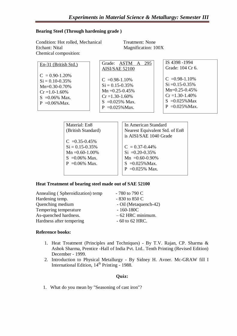
Bearing Steel (Through hardening grade )
Condition: Hot rolled, Mechanical Treatment: None
Etchant: Nital Magnification: 100X
Chemical composition:
En-31 (British Std.)
C = 0.90-1.20%
Si = 0.10-0.35%
Mn=0.30-0.70%
Cr =1.0-1.60%
S =0.06% Max.
P =0.06%Max.
Material: En8
(British Standard)
C =0.35-0.45%
Si = 0.15-0.35%
Mn =0.60-1.00%
S =0.06% Max.
P =0.06% Max.
In American Standard
Nearest Equivalent Std. of En8
is AISI/SAE 1040 Grade
C = 0.37-0.44%
Si =0.20-0.35%
Mn =0.60-0.90%
S =0.025%Max.
P =0.025% Max.
Heat Treatment of bearing steel made out of SAE 52100
Annealing ( Spheroidization) temp - 780 to 790 C
Hardening temp. - 830 to 850 C
Quenching medium - Oil (Metaquench-42)
Tempering temperature - 160-180C
As-quenched hardness. – 62 HRC minimum.
Hardness after tempering - 60 to 62 HRC.
Reference books:
1. Heat Treatment (Principles and Techniques) - By T.V. Rajan, CP. Sharma &
Ashok Sharma, Prentice -Hall of India Pvt. Ltd.. Tenth Printing (Revised Edition)
December - 1999.
2. Introduction to Physical Metallurgy - By Sidney H. Avner. Mc-GRAW fill I
International Edition, 14th Printing - 1988.
Quiz:
1. What do you mean by "Seasoning of cast iron"?
IS 4398 -1994
Grade: 104 Cr 6.
C =0.98-1.10%
Si =0.15-0.35%
Mn=0.25-0.45%
Cr =1.30-1.40%
S =0.025%Max
P =0.025%Max.
Grade: ASTM A 295
AISI/SAE 52100
C =0.98-1.10%
Si = 0.15-0.35%
Mn =0.25-0.45%
Cr =1.30-1.60%
S =0.025% Max.
P =0.025%Max.

Experiments in Material Science & Metallurgy: Semester III
2. What are the advantages of cast iron over steel?
3. Why are the alloys of iron and carbon with carbon percentage 2.0 to 6.67 called as
cast iron?

Experiments in Material Science & Metallurgy: Semester III
4. Draw microstructure of the following cast irons and comment on it.
a. Gray cast iron
b. Nodular cast iron
c. White cast iron

Experiments in Material Science & Metallurgy: Semester III
5. Draw microstructure of the following ferrous materials and comment on it.
a. Low carbon steel
b. Medium carbon steel
c. Stainless steel
d. Bearing steel
e. En-8.
Date: Sign: Grade:
Experiments in Material Science & Metallurgy: Semester III
QUENCHING MEDIA EOR HARDENING OF STEEL
Experiment No:-7 Date:
Objective: To examine the effect of quenching media on hardening of steel.
Tools & Instruments:
• Quenching media (brine, water, oil and air).
• Quenching bath.
• Furnace.
• Rock well hardness testing machine.
Theory:
As applied to the heat treatment of steels, quenching is a process of rapid cooling of steel
from austenizing temperature. Quenching results in the transformation of austenite into
martensite (a non-equilibrium constituent having body center tetragonal structure). This
highly stressed structure increases hardness of steel. Under ideal conditions, all the heat
absorbed by the medium should reject to the surroundings immediately. The effectiveness
of a quenching process largely depends on the characteristics of the quenched used. In
addition to it, some other factors such as chemical composition of the steel, design of
steel component, and surface conditions of steel component also control the efficiency of
the quenching process.
The removal of heat during quenching is complex in the sense that, the heat is removed in
the three stages. When heated steel is quenched in a suitable medium, it shows
temperature gradient between the surface and the core of steel. The surface cools down
more rapidly than does the core. As a result of this the following stages are observed.
(a) Vapour blanket stage:
Due to high temperature of work piece the quenching medium gets vaporized at the
surface of metal and forms a thin vapor film (blanket). This vapour film, being poor
conductor of heat, checks further cooling of the work piece. The work piece is cooled
at the stage by conduction and radiation through the vapor film.
(b) Vapour transport cooling stage or liquid boiling stage:
The vapor film is suitable up to 400°C. As soon as the vapour film is broken, the
quenchant comes in contact with surface of the work-piece and is immediately pushed
away from it in the form of bubbles. Fresh coolant now comes in contact with the
work piece surface and the process is repeated. Very rapid cooling takes place at this
stage as the quenchant is always in contact with the surface of the work piece.
(c) Liquid cooling stage:
In this stage the surface temperature of the work-piece reaches the boiling point of the
quenchant. Cooling at this stage takes place by both conduction and convection
processes. The rate of cooling is the slowest at this stage.

Experiments in Material Science & Metallurgy: Semester III
The quenching medium must show effective heat removal during quenching. It should
posses the following characteristics:
1. High initial cooling rate to avoid transformation at nose region.
2. Slow cooling rate below nose to minimize cracking and distortion.
The various quenching mediums used are as following in the decreasing severity of
quenching.
1. Water solution of 10% sodium chloride (brine).
2. Tap water.
3. Fused or liquid salt.
4. Soluble oils.
5. Oil. and
6. Air.
Alloy steels have lower critical cooling rate (CCR) and hence, they can be hardened
by air cooling. Oil quenching is used for high carbon steels as they show higher CCR.
Medium carbon steels have very high CCR so; water or brine quenching is required.
Even water or brine cooling cannot harden extremely low carbon steels.
Experimental Setup: Cooling baths containing different quenching medium are
required.
Experimental Procedure:
1. Prepared specimens from ms of 1 inch diameter and 4 inches long.
2. Heat this specimen in furnace for 30 minutes for austenitic transformation. This
temperature depends on the carbon content of the steel.
3. Remove specimens from furnace and immerse in different quenching baths for
about 5 to 10 minutes.
4. Prepare the surface of specimen.
5. Measure hardness of each specimen with the Rockwell hardness-testing machine.
6. Tabulate these observations.
Observation table:
Sr. No. Quenching media. Hardness before Hardness after
Quenching. quenching
1
2
3
4
5

Experiments in Material Science & Metallurgy: Semester III
Conclusion:
Reference books:
1. Heat Treatment (Principles and Techniques) - By T.V. Rajan, CP. Sharma & Ashok
Sharma. Prentice Hall of India Pvt. Ltd.. Tenth Printing. December - 1999.
2. Introduction to Physical Metallurgy - By Sidney H. Avner, Mc-GRAW HILL
International Edition, 14th Printing - 1988.
QUIZ:
1. State the major disadvantage associated with water quenching.
2. Water is the most commonly used quenching medium. Why?

Experiments in Material Science & Metallurgy: Semester III
3. What is CCR? What is significance of CCR to obtain hard martensilic structure?
4. Explain the mechanism of heat removal during quenching.

Experiments in Material Science & Metallurgy: Semester III
5. Explain the transformation of austenite to martensite.
Date: Sign: Grade:

Experiments in Material Science & Metallurgy: Semester III
HARDENABILITY OF STEEL
Experiment No:-8 Date:
Objective: To find hardenability of steel.
Tools & Instruments:
1. Jominy End-quench apparatus.
2. Water jet setting gauge.
3. Rockwell hardness testing machine.
4. Standard specimen of 1" diameter and 4" long with collar at one end.
5. Muffle Furnace.
Theory:
Hardenability is the ease with which a steel piece can be hardened. It is defined as the
depth upto which 50 % martensite or hardness of Rc54 is observed. The hardness of
hardened steel is measured on its surface. The surface shows higher hardness, which
decreases towards the center of steel specimen. This variation in hardness along its cross
section may be termed as Hardenability. It is not related to the maximum hardness, and
the term hardness and hardenability should be clearly distinguished. Hardenability is very
important property in heat treatment of steel. It provides following information in heal
treatment:
Maximum hardness that can be obtained on the surface of steel.
Depth & distribution of hardness across a cross section,
Required cooling rate or quenching medium,
Stress level on surface etc.
Hardenability depends on the following factors:
Composition of steel.
Austenitic grain size.
Homogeneity of austenite.
Non-metallic inclusions in the austenite, and
Presence of alloying elements (i.e. undissolved carbides and nitrides in the
austenite).
Besides this, the coolant used for quenching, the size of the specimen, and the criterion
used for assessment of hardenability also affect the extent of hardenability.
Hardenability can be measured by any one of the following methods:
1. Jominy end quench test,
2. Grossman's critical diameter method,
3. Fracture test, and
4. ardenability estimation from chemical composition.
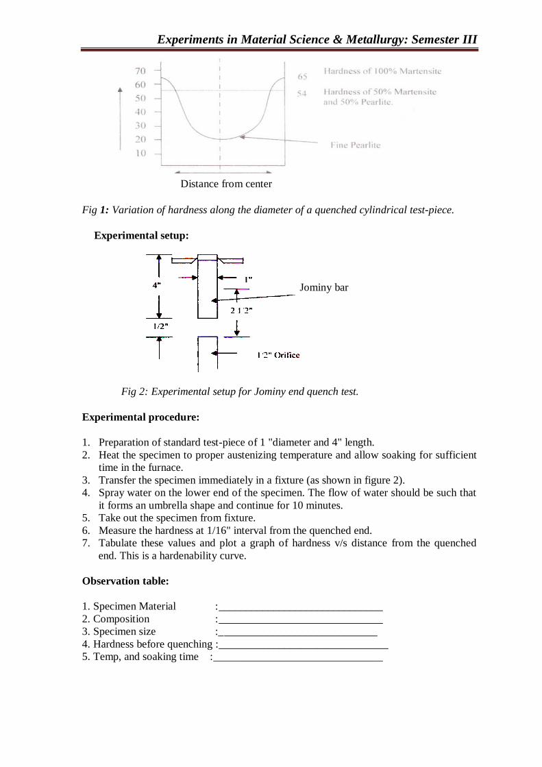
Experiments in Material Science & Metallurgy: Semester III
Fig 1: Variation of hardness along the diameter of a quenched cylindrical test-piece.
Experimental setup:
Fig 2: Experimental setup for Jominy end quench test.
Experimental procedure:
1. Preparation of standard test-piece of 1 "diameter and 4" length.
2. Heat the specimen to proper austenizing temperature and allow soaking for sufficient
time in the furnace.
3. Transfer the specimen immediately in a fixture (as shown in figure 2).
4. Spray water on the lower end of the specimen. The flow of water should be such that
it forms an umbrella shape and continue for 10 minutes.
5. Take out the specimen from fixture.
6. Measure the hardness at 1/16" interval from the quenched end.
7. Tabulate these values and plot a graph of hardness v/s distance from the quenched
end. This is a hardenability curve.
Observation table:
1. Specimen Material : ______________________________
2. Composition : ______________________________
3. Specimen size :_ ____________________________
4. Hardness before quenching : _______________________________
5. Temp, and soaking time : _______________________________
Jominy bar
Distance from center
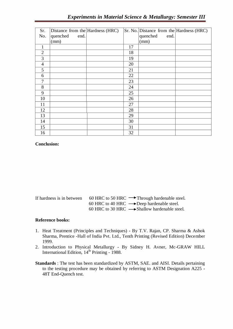
Experiments in Material Science & Metallurgy: Semester III
Sr.
No.
Distance from the
quenched end.
(mm)
Hardness (HRC) Sr. No. Distance from the
quenched end.
(mm)
Hardness (HRC)
1 17
2 18
3 19
4 20
5 21
6 22
7 23
8 24
9 25
10 26
11 27
12 28
13 29
14 30
15 31
16 32
Conclusion:
If hardness is in between 60 HRC to 50 HRC Through hardenable steel.
60 HRC to 40 HRC Deep hardenable steel.
60 HRC to 30 HRC Shallow hardenable steel.
Reference books:
1. Heat Treatment (Principles and Techniques) - By T.V. Rajan, CP. Sharma & Ashok
Sharma, Prentice -Hall of India Pvt. Ltd., Tenth Printing (Revised Edition) December
1999.
2. Introduction to Physical Metallurgy - By Sidney H. Avner, Mc-GRAW HILL
International Edition, 14lh Printing - 1988.
Standards : The test has been standardized by ASTM, SAE. and AISI. Details pertaining
to the testing procedure may be obtained by referring to ASTM Designation A225 -
48T End-Quench test.

Experiments in Material Science & Metallurgy: Semester III
Quiz:
1. State and explain the factors influencing Hardenability of steel.
2. Does carbon content affect the Hardenability of steel? What is the importance of
chemical composition of steel with respect to Hardenability?
3. Give any four etching reagents use in microscopy.

Experiments in Material Science & Metallurgy: Semester III
4. Define and explain the term ―Severity of quench‖
5. Difference between hardness and Hardenability.
Date: Sign: Grade:
Experiments in Material Science & Metallurgy: Semester III
EFFECT OF SECTION SIZE ON MATERIAL HARDNESS
Experiment No:-9 Date:
Objectives: To determine the effect of section si/e on hardness of the material developed
during quenching.
Tools & Instruments:
1. Muffle Furnace
2. Abrasive cut-off machine
3. Quenching bath
4. Hardness tester
5. Lathe machine
Theory:
Quenching refers to the process of rapidly cooling metal parts from the austenitizing or
solution treating temperature typically from within the range of 815 - 870°C for steel.
Most steel including carbon, low alloy. & tool steels are quenched to produce controlled
amount of martensite in the microstructure.
The selection of the quenching medium depends on the hardenability of the particular
alloy, the section thickness and shape involved, and cooling rates needed to achieve the
desired microstructure. flic rate of heat transfer from a part being quenched may be
affected by oxidation of the surface, section thickness, quenching medium characteristics,
agitation of the quenching bath etc.
Oxidations of the surface can either increases or decrease the heat transfer rate depending
on the thickness of the oxide developed. Agitation refers to liquid quentchant movement
relative to part. Agitation is usually obtained by moving the part in the liquid, but in some
cases it is obtained by moving the parts in the liquid. Agitation has an extremely
important influence on the heat transfer. Agitation causes mechanical disruption of the
vapour blanket and a faster transition to liquid boiling stage. Increasing agitation usually
produces a shorter vapour blanket stage and faster cooling rate in all three stages of
cooling. The cooling rates are also functions of the thickness and geometry of the part.
Section size effect:
The effect of section size on cooling rates for varying cross section of the steel is
illustrated in Fig.l. Cooling rates dramatically decrease with increase in section thickness.
With heavy section, the cooling rate is limited by the rate of heat conduction from the
interior to the surface. Rapid cooling of the center of an extremely large section is
impossible by any quenching method because of the mass-effect. Therefore, when deep
hardening a heavy section, it is necessary to use an alloy steel with higher hardcnability.

Experiments in Material Science & Metallurgy: Semester III
The change in section thickness of parts affects the shape of cooling rates.
Consequently, the hardness and strength of parts being quenched may get affected
Experimental Procedure:
1. Prepare a test piece as per dimension shown in Fig. 1.
2. Heat the test piece in furnace for 30 minutes at austeniging temperature.
3. Remove the test-piece form furnace quickly and immerse in quenching bath
(water/oil).
4. Measure the hardness at center and at surface for different section.
5. Tabulate these observations.
6. Plot graph between variation in hardness and section thickness
Fig.1 Test piece for experiment
Observation Table:
Material Section
thickness
(mm)
Hardness at
surface
Hardness at
center
Variation in hardness
at surface and center
25 mm 25 mm 25 mm 25 mm
Experiments in Material Science & Metallurgy: Semester III
Conclusion(s):
Reference books:
1. ASM Hand Book, Titled 'Heat Treating'. Volume 4. Chapter: Quenching of Steel Page
No. 67 - 75
2. Heat Treatment (Principles and Techniques) - By T.V. Rajan, CP. Sharma & Ashok
Sharma. Prentice -Hall of India Pvt. Ltd., Tenth Printing (Revised Edition) December
- 1999.
Quiz :
1. In heat treatment, why austenitizing of a component (steel) is required before
hardening?
2. List the factor affecting the rate of heat transfer during quenching of steel.

Experiments in Material Science & Metallurgy: Semester III
3. What factors need to be considered before selecting a quenching medium and
why?
4. Explain, in brief, how the cross section of a component affects the cooling rate
during quenching
5. List the requirements of a good quenching medium.

Experiments in Material Science & Metallurgy: Semester III
6. Briefly discuss the advantages and disadvantages of oil as a quenching medium.
Date: Sign: Grade:
Experiments in Material Science & Metallurgy: Semester III
ULTRASONIC METHOD FOR THE DETECTION OF SURFACE AND
SUBSURFACE FLAWS
Experiment No:-10 Date:
Objective: To study ultrasonic method for the detection of surface and subsurface flaws.
Tools & Instruments:
1. Electronic signal generator,
2. Transducer (Probe or search unit),
3. Echo-signal amplifier,
4. Display device (oscilloscope),
5. Calibration blocks,
6. Couplant etc,
Working principle:
In ultrasonic inspection method, beams of high frequency sound waves are introduced
into materials for detection of surface and subsurface flaws in the material. The sound
waves travel through the materials with some attendant loss of energy (attenuation) and
are reflected at interfaces. The reflected beam is displayed and then analyzed to define the
presence and location of flaws or discontinuities.
Major Variable in Ultrasonic Inspection:
• Frequency of the ultrasonic wave.
• Acoustic impedance.
• Angle of incidence if ultrasonic wave.
• Critical angles.
• Beam intensity.
Basic Inspection Methods:
The two methods of ultrasonic inspection are:
1. Transmission method: It involves only the measurement of signal attenuation.
2. Pulse echo method: It can be used to measure both transit time and signal attenuation.
The pulse echo method, which is the most widely used ultrasonic method, involves the
detection of echoes produced when an ultrasonic pulse is reflected from a discontinuity or
an interface of a test piece. This method is used in flaw location and thickness
measurements. Flaw depth is determined from the time of flight between the initial pulse
and the echo produced by a flaw. Flaw depth might also be determined by the relative-
transit time between the echo produced by a flaw and the echo from the back surface.
Advantages:
• Superior penetrating power, which allows the detection of flaws deep in the part.
• High sensitivity, permitting the detection of internally small flaws.
Experiments in Material Science & Metallurgy: Semester III
• Greater accuracy than other nondestructive methods in determining the position of
internal Haws, estimating their size, and characterizing their orientation, shape, and
nature.
• Only one surface needs to the accessible.
• Operation is electronic, which provides almost instantaneous indication of flaws.
• Portability
• Non hazardous to operation or to nearby personnel.
• Provides an output that can be processed digitally by a computer to characterize
defects and to determine material properties.
Disadvantages:
• Manual operation requires careful attention by experienced technicians.
• Extensive technical knowledge is required for the development of inspection
procedure.
• Rough, irregular shape and in homogeneous parts are difficult to inspect.
• Couplant are needed to provide effective transfer of ultrasonic wave energy between
transducers and being inspected.
• Discontinuities that are present in a shallow layer immediately beneath the surface
may not be detectable.
• Reference standards are needed, both for calibrating the equipment and for
characterizing.
Applications:
• Mill component rolls, shafts, drivers and press columns.
• Power equipment: turbine, forging, generator rotors, pressure piping, pressure vessels
etc.
• Jet engine parts: turbine and compressor forging, and gear blocks.
• Air craft components: Forging stock, frame section etc.
• Machinery materials: Die blocks, tool steels and drill pipe.
• Rail road parts: Axles, wheels, track and welded rail.
• Automotive parts: Forging, ductile castings, welded components, bearings etc.
Reference books:
1. Heat Treatment (Principles and Techniques) - By T.V. Rajan. CP. Sharma & Ashok
Sharma, Prentice -Hall of India Pvt. Ltd., Tenth Printing (Revised Edition) December
- 1999.
2. Introduction to Physical Metallurgy - By Sidney H. Avner. Mc-GRAW HILL
International Edition, 14th Printing - 1988.
Quiz:
1. What do you mean by attenuation?

Experiments in Material Science & Metallurgy: Semester III
2. What role the part geometry plays in ultrasonic inspection?
3. What are the different types of probes generally used in ultrasonic inspection?
4. Why calibration of ultrasonic equipment is required?

Experiments in Material Science & Metallurgy: Semester III
5. What types of calibration blocks are used in ultrasonic inspection
6. Why couplant is required in ultrasonic inspection method?
Date: Sign: Grade:
Experiments in Material Science & Metallurgy: Semester III
NON DESTRUCTIVE TEST
Experiment No:-11 Detection of flaws in materials through dye-penetrant test.
Tools & Instruments:
1. Cleaner Spray,
2. Penetrate Spray,
3. Developer Spray,
4. Welded Specimen,
Working principle:
The principle of liquid penetrate test is that is that liquids used enter small opening
such as cracks by capillarity action. The rate and extent of this action are dependent upon
which such a properties are surface tension, cohesion, adhesion and viscosity. They are
also influenced by factors such as the condition of the surface of material.
For the liquid to penetrate effectively, the surface of the material must be thoroughly
cleaned of all material that would obstruct the entrance of the liquid in to defect.
After cleaning the liquid penetrate is applied evenly over the surface and allowed to
remain long enough to permit penetrate into possible discontinuous.
The liquid is then completely removed from the surface of the component and either a
wet or a dry developer is applied. The liquid that has to applied the defect will then bleed
out onto the surface and the developer will help delineated them.
Procedure:

Experiments in Material Science & Metallurgy: Semester III
Application:
Reference books:
3. Heat Treatment (Principles and Techniques) - By T.V. Rajan. CP. Sharma & Ashok
Sharma, Prentice -Hall of India Pvt. Ltd., Tenth Printing (Revised Edition) December
- 1999.
4. Introduction to Physical Metallurgy - By Sidney H. Avner. Mc-GRAW HILL
International Edition, 14th Printing - 1988.
Date: Sign: Grade:

Experiments in Material Science & Metallurgy: Semester III