
Smittybilt Winches & Accessories Installation Instructions
24
Transcript of Smittybilt Winches & Accessories Installation Instructions
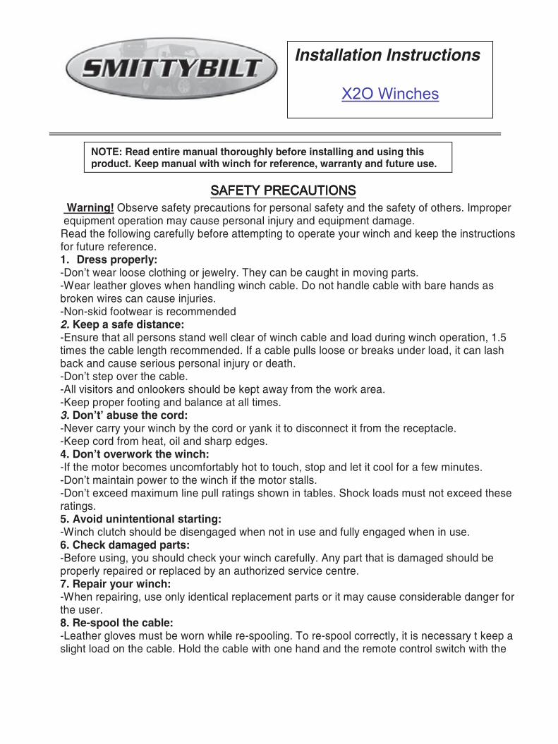
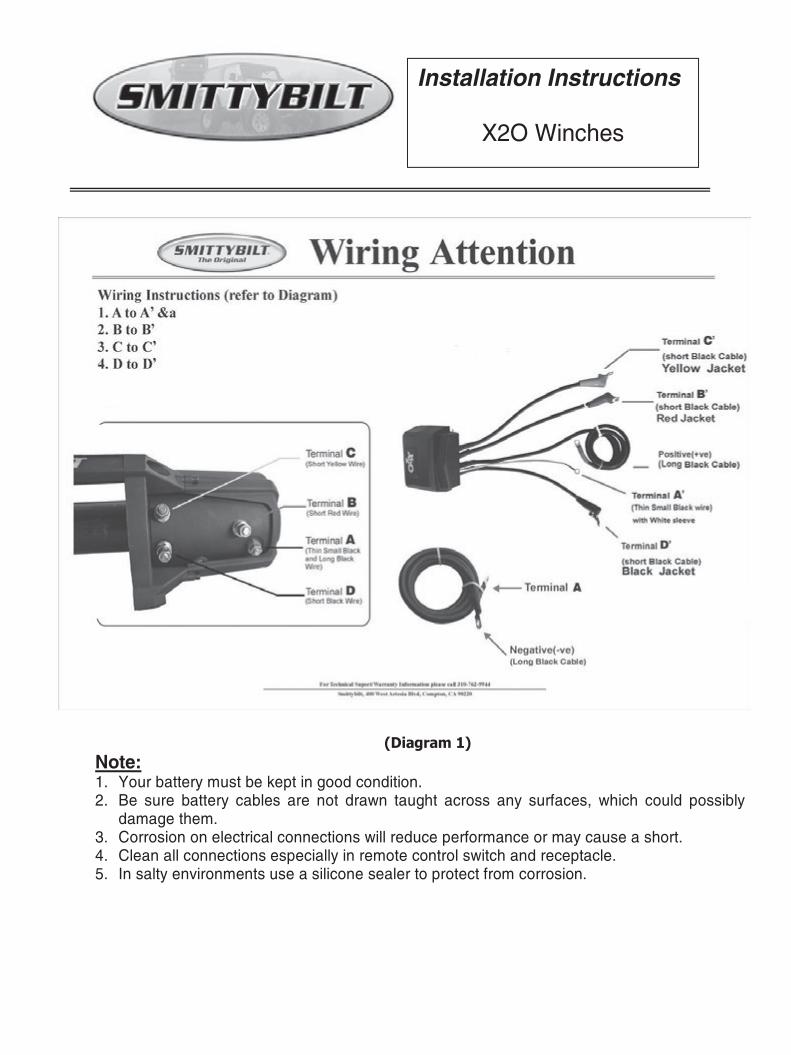
NEVER operate winch with less than 10 wraps of rope around the drum. The terminal end is to prevent the rope from unraveling, it is NOT a load bearing attachment point. Improper installation and /or spooling out to last layer will put a load on the terminal end and the rope will release from the terminal. Always re-spool winch rope under a minimum 1000 lb. load before each use. Prior to your next pull, re-spool winch line under at least 1000lbs of resistance to prevent damageto winch line during next recovery.
6wraps of steel cable or 10 wraps of synthetic rope minimum on the drum. If this is not pra-tical use a snatch block and double line arrangement.
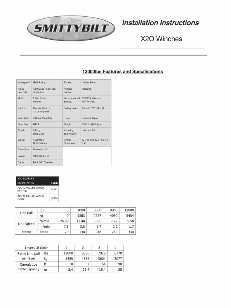
1000lbs(460kgs)
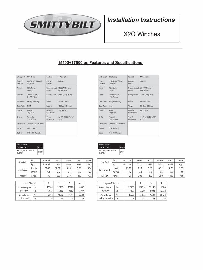
1000lbs(460kgs)
6 wraps of steel cable or10 wraps of synthetic rope remain on the winch drum when this mark appears at the rollers.No recovery should be attempted beyond this marking.
17. Do not attempt to exceed the pulling limits of this winch.18. Do not drive your vehicle to assist the winch in any way. Vehicle movement in combi-
19. Shock loads when winching are dangerous! A shock load occurs when an increase force

Control box can sit anywhere over the drum, determine best location for you.(left, center, right)
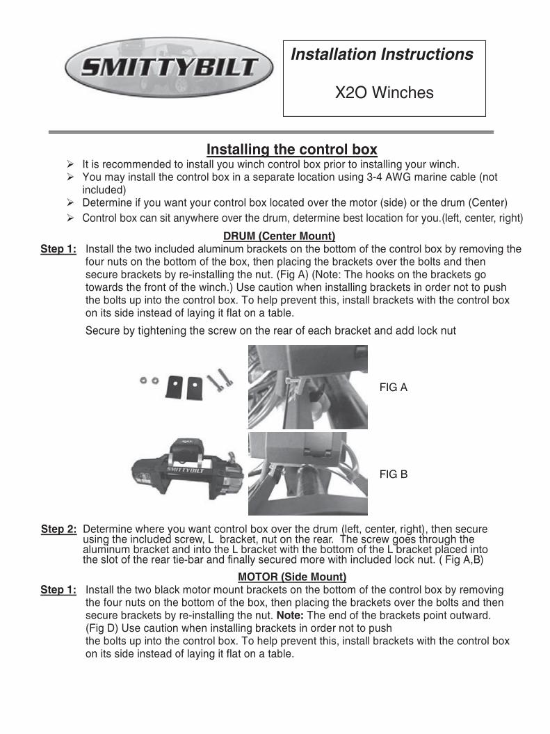
Secure by tightening the screw on the rear of each bracket and add lock nut
Determine where you want control box over the drum (left, center, right), then secure using the included screw, L bracket, nut on the rear. The screw goes through the aluminum bracket and into the L bracket with the bottom of the L bracket placed into the slot of the rear tie-bar and finally secured more with included lock nut. ( Fig A,B)
Step 2:
leftward
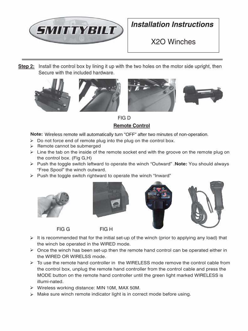
It is recommended that for the initial set-up of the winch (prior to applying any load) that the winch be operated in the WIRED mode.Once the winch has been set-up then the remote hand control can be operated either in the WIRED OR WIRELSS mode.To use the remote hand controller in the WIRELESS mode remove the control cable from the control box, unplug the remote hand controller from the control cable and press the MODE button on the remote hand controller until the green light marked WIRELESS is illumi-nated.Wireless working distance: MIN 10M, MAX 50M.Make sure winch remote indicator light is in correct mode before using.
rightward
Remote cannot be submerged
Wireless remote will automatically turn "OFF" after two minutes of non-operation.
A. Do not use as a hoistB. Power out only to relieve slack on cable or rope. Excessive powering out can cause damage to internal components.C. Do not use to hold loadsD. Do not use to drop loads (example-unloading vehicles)
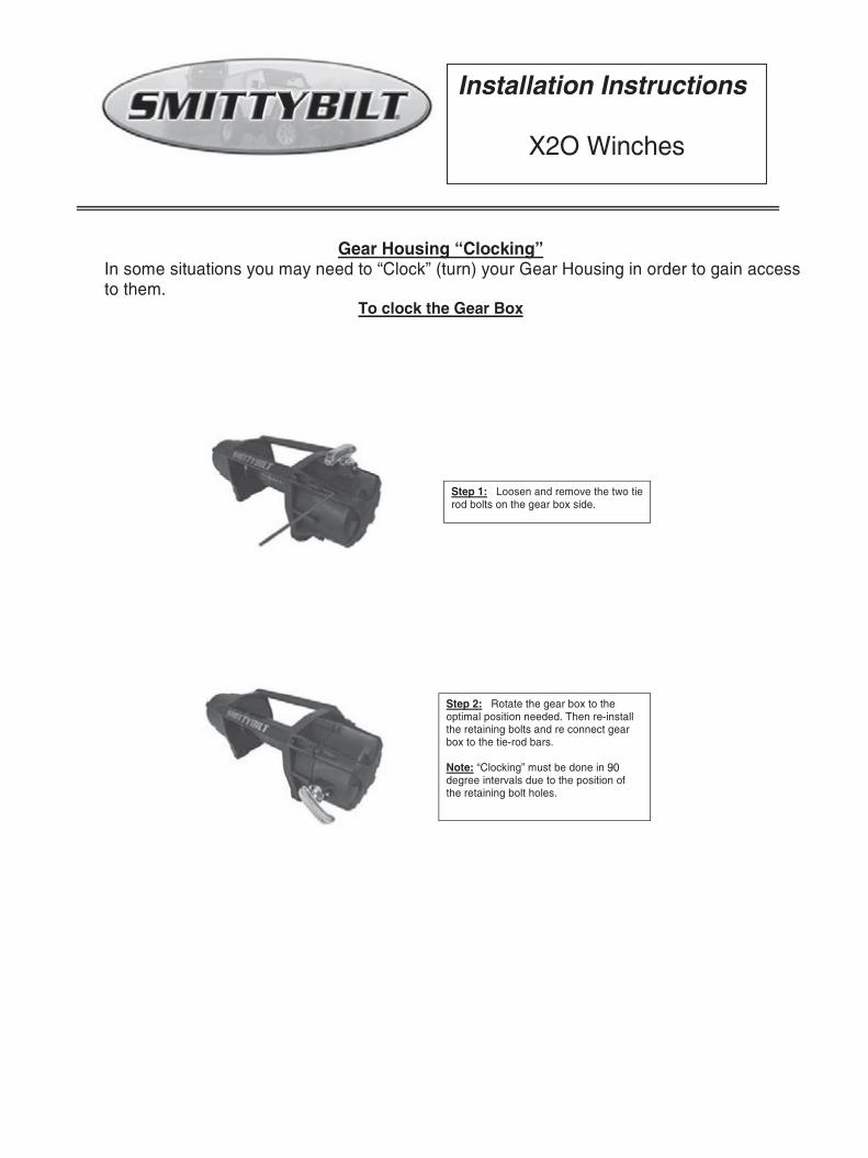
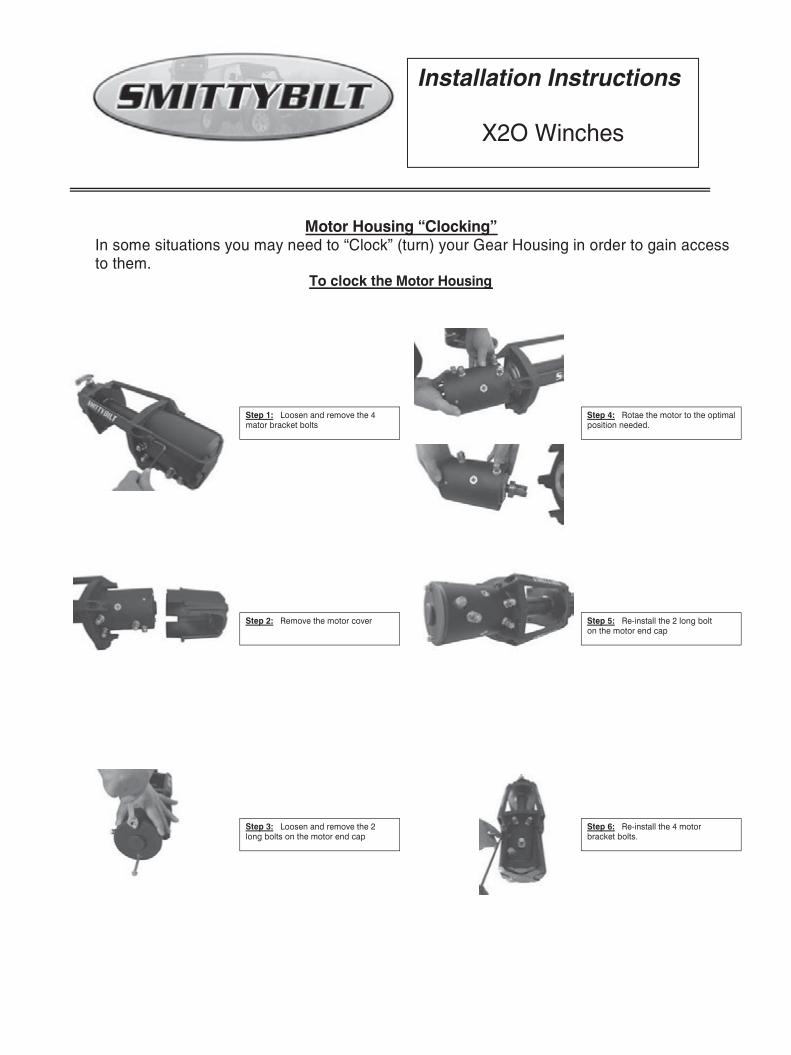
Step 1: Loosen and remove the 4mator bracket bolts
Step 2: Remove the motor cover
Step 4: Rotae the motor to the optimalposition needed.
Step 3: Loosen and remove the 2long bolts on the motor end cap
Step 5: Re-install the 2 long bolton the motor end cap
Step 6: Re-install the 4 motorbracket bolts.
Motor Housing “Clocking”
Motor Housing
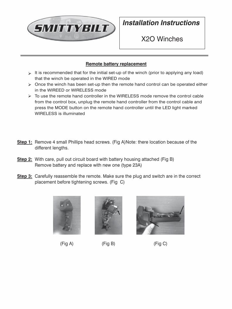
It is recommended that for the initial set-up of the winch (prior to applying any load) that the winch be operated in the WIRED modeOnce the winch has been set-up then the remote hand control can be operated either in the WIREED or WIRELESS modeTo use the remote hand controller in the WIRELESS mode remove the control cable from the control box, unplug the remote hand controller from the control cable and press the MODE button on the remote hand controller until the LED light marked WIRELESS is illuminated
Remove 4 small Phillips head screws. (Fig A)Note: there location because of the different lengths.
Carefully reassemble the remote. Make sure the plug and switch are in the correct placement before tightening screws. (Fig C)
With care, pull out circuit board with battery housing attached (Fig B)Remove battery and replace with new one (type 23A)
Step 1:
Step 2:
Step 3:
Remote battery replacement
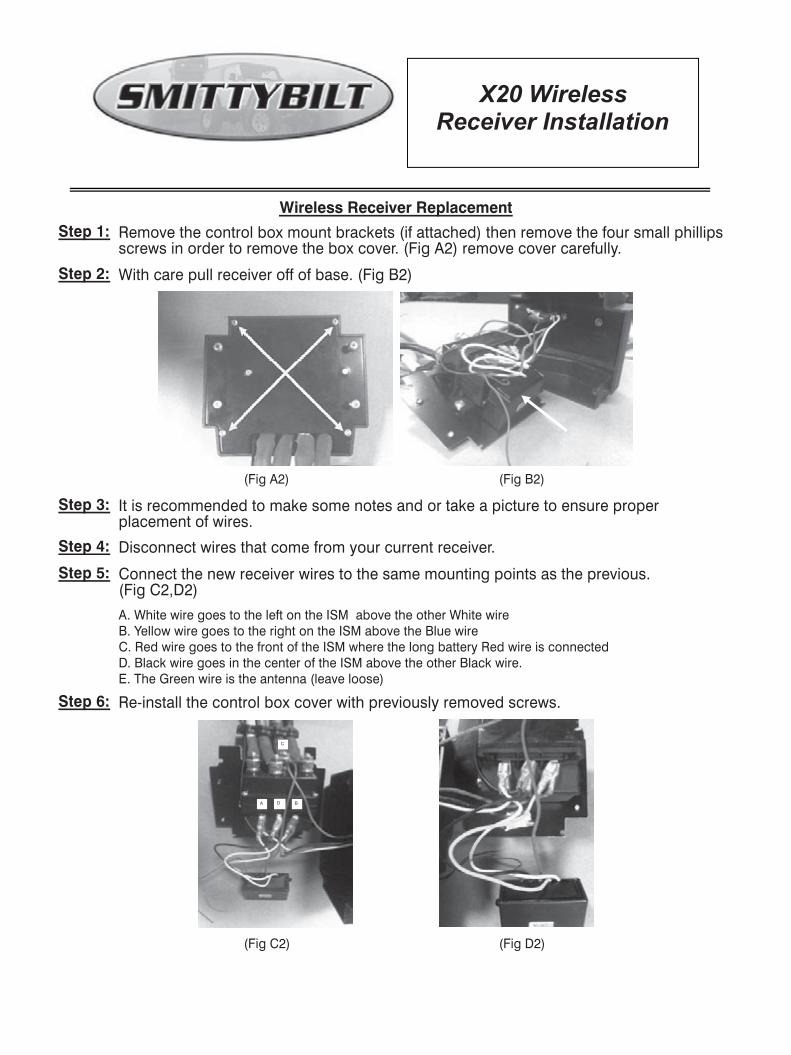
Step 1: Remove the control box mount brackets (if attached) then remove the four small phillips screws in order to remove the box cover. (Fig A2) remove cover carefully.
Step 2:
Step 3:
With care pull receiver off of base. (Fig B2)
It is recommended to make some notes and or take a picture to ensure proper placement of wires.
Step 4: Disconnect wires that come from your current receiver.
Step 5: Connect the new receiver wires to the same mounting points as the previous. (Fig C2,D2)
Step 6: Re-install the control box cover with previously removed screws.
(Fig A2) (Fig B2)
(Fig C2) (Fig D2)
A. White wire goes to the left on the ISM above the other White wireB. Yellow wire goes to the right on the ISM above the Blue wireC. Red wire goes to the front of the ISM where the long battery Red wire is connectedD. Black wire goes in the center of the ISM above the other Black wire.E. The Green wire is the antenna (leave loose)
Wireless Receiver Replacement
7/16