sMHF single and dual dc-dc converters -...
15
DESCRIPTION The Interpoint ® SMHF Series™ of 28 volt dc-dc converters offers a wide input voltage range of 16 to 45 volts and up to 15 watts of output power. The units are capable of withstanding transients up to 50 volts for up to 50 ms. SCREENING SMHF converters offer screening to Class H or K and radiation hardness assurance (RHA) levels P - 30 krad(Si), L - 50 krad(Si) or R - 100 krad(Si). Single event effects (SEE) LET performance to 86 MeV cm 2 /mg. See Table 10 on page 15 for more information. CONVERTER DESIGN The SMHF converters are switching regulators that use a quasi-square wave, single-ended forward converter design with a constant switching frequency of 550 kHz typical. Isolation between input and output circuits is provided with a transformer in the forward path and a temperature compensated opto-coupler in the feedback control loop. The opto-coupler is radiation tolerant and is especially selected for space applications. Dual output models maintain cross regulation with tightly coupled output magnetics. Up to 70% of the total output power is available from either output, providing the opposite output is simultaneously carrying 30% of the total output power. Predictable current limit is accomplished by directly monitoring the output load current and providing a constant current output above the overload point. The SMHF converter’s feed-forward compensation system provides excellent dynamic response and noise rejection. Audio rejection is typically 50 dB. Typical output voltage response for a 50% to 100% step load transient is as low as 1.8% with a 150 µs recovery time, typical. See Table 5 on page 5 for more information. SMHF converters provide an inhibit terminal that can be used to disable internal switching, resulting in no output and very low quiescent input current. The converter is inhibited when the inhibit pin is pulled low. The unit is enabled when the pin, which is internally connected to a pull-up resistor, is left unconnected or is connected to an open-collector gate. See Table 5 on page 5 for more information. The SMHF Series’ synchronization feature allows the user to match the switching frequency of the converter to the frequency of the system clock. This allows the user to adjust the nominal 550 kHz operating frequency to any frequency within the range of 500 kHz to 600 kHz by applying a compatible input of the desired frequency to pin 5. SMHF Series converters provide short circuit protection by restricting the output current to approximately 140% of the full load output current. The output current is sensed in the secondary stage to provide highly predictable and accurate current limiting, and to eliminate foldback characteristics. Undervoltage lockout prevents the units from operating below approximately 14 volts input to keep system current levels smooth, especially during initialization or re-start operations. FEATURES • Radiation tolerant space dc-dc converter - Single event effects (SEE) LET performance to 86 MeV cm 2 /mg - Total ionizing dose (TID) guaranteed per MIL-STD-883 method 1019, radiation hardness assurance (RHA) P = 30 krad(Si), L = 50 krad(Si), R = 100 krad(Si) - 50 - 300 rad(Si)/sec dose rate (Condition A) - 10 mrad(Si)/sec dose rate (Condition D) • Operating temperature -55°C to +125°C • Qualified to MIL-PRF-38534 Class H and K • Input voltage range 16 to 45 volts • Transient protection 50 volts for 50 ms • Fully isolated • Fixed high frequency switching • Inhibit function • Synchronization input • Indefinite short circuit protection • Undervoltage lockout MODELS OUTPUT VOLTAGE (V) SINGLE DUAL 3.3 ±5 5 ±12 5.2 ±15 12 15 SMHF Single and Dual DC-DC Converters Crane Aerospace & Electronics Power Solutions - Interpoint Products 10301 Willows Road NE, Redmond, WA 98052 +1 425-882-3100 • [email protected] www.craneae.com/interpoint Page 1 of 15 16-45 VOLT INPUT – 15 WATT SMHF Rev AF - 2015.10.28 Crane Aerospace & Electronics Power Solutions
Transcript of sMHF single and dual dc-dc converters -...

descriptionThe Interpoint® SMHF Series™ of 28 volt dc-dc converters offers a wide input voltage range of 16 to 45 volts and up to 15 watts of output power. The units are capable of withstanding transients up to 50 volts for up to 50 ms.
ScreeningSMHF converters offer screening to Class H or K and radiation hardness assurance (RHA) levels P - 30 krad(Si), L - 50 krad(Si) or R - 100 krad(Si). Single event effects (SEE) LET performance to 86 MeV cm2/mg. See Table 10 on page 15 for more information.
converter DeSignThe SMHF converters are switching regulators that use a quasi-square wave, single-ended forward converter design with a constant switching frequency of 550 kHz typical. Isolation between input and output circuits is provided with a transformer in the forward path and a temperature compensated opto-coupler in the feedback control loop. The opto-coupler is radiation tolerant and is especially selected for space applications.
Dual output models maintain cross regulation with tightly coupled output magnetics. Up to 70% of the total output power is available from either output, providing the opposite output is simultaneously carrying 30% of the total output power. Predictable current limit is accomplished by directly monitoring the output load current and providing a constant current output above the overload point.
The SMHF converter’s feed-forward compensation system provides excellent dynamic response and noise rejection. Audio rejection is typically 50 dB. Typical output voltage response for a 50% to 100% step load transient is as low as 1.8% with a 150 µs recovery time, typical. See Table 5 on page 5 for more information.
SMHF converters provide an inhibit terminal that can be used to disable internal switching, resulting in no output and very low quiescent input current. The converter is inhibited when the inhibit pin is pulled low. The unit is enabled when the pin, which is internally connected to a pull-up resistor, is left unconnected or is connected to an open-collector gate. See Table 5 on page 5 for more information.
The SMHF Series’ synchronization feature allows the user to match the switching frequency of the converter to the frequency of the system clock. This allows the user to adjust the nominal 550 kHz operating frequency to any frequency within the range of 500 kHz to 600 kHz by applying a compatible input of the desired frequency to pin 5.
SMHF Series converters provide short circuit protection by restricting the output current to approximately 140% of the full load output current. The output current is sensed in the secondary stage to provide highly predictable and accurate current limiting, and to eliminate foldback characteristics.
Undervoltage lockout prevents the units from operating below approximately 14 volts input to keep system current levels smooth, especially during initialization or re-start operations.
Features• Radiation tolerant space dc-dc converter
- Single event effects (SEE) LET performance to 86 MeV cm2/mg
- Total ionizing dose (TID) guaranteed per MIL-STD-883 method 1019, radiation hardness assurance (RHA) P = 30 krad(Si), L = 50 krad(Si), R = 100 krad(Si)
- 50 - 300 rad(Si)/sec dose rate (Condition A) - 10 mrad(Si)/sec dose rate (Condition D)
• Operating temperature -55°C to +125°C• Qualified to MIL-PRF-38534 Class H and K• Input voltage range 16 to 45 volts • Transient protection 50 volts for 50 ms• Fully isolated• Fixed high frequency switching• Inhibit function• Synchronization input• Indefinite short circuit protection• Undervoltage lockout
MODELSOUTPUT VOLTAgE (V)
SINgLE DUAL3.3 ±55 ±12
5.2 ±151215
sMHF single and dual dc-dc converters
Crane Aerospace & ElectronicsPower Solutions - Interpoint Products10301 Willows Road NE, Redmond, WA 98052+1 425-882-3100 • [email protected]/interpoint
Page 1 of 15
16-45 Volt input – 15 Watt
SMHF Rev AF - 2015.10.28
Crane Aerospace & Electronics Power Solutions

PWMController
ID
IC
Limit
Regulator
Ref.
OutputCommon
PositiveOutput
PositiveInput
Inhibit
InputCommon
5 μH
2 μF
FETDriver
Figure 1: SMHF Single output, Block DiagraM
PWMController
ID
IC
Limit Ref.
OutputCommon
PositiveOutput
Negative Output
PositiveInput
Inhibit
InputCommon
5 μH
2 μF
FETDriver
RS
RS
L2B
L2A
Regulator
Figure 2: SMHF Dual output, Block DiagraM
sMHF single and dual dc-dc converters
Page 2 of 15
16-45 Volt input – 15 Watt
www.craneae.com/interpointSMHF Rev AF - 2015.10.28
Crane Aerospace & Electronics Power Solutions

Figure 3: pin out
BOTTOM VIEWSMHF SINGLE AND DUAL
NON-FLANGED OR FLANGED
Dot on top of cover indicates pin one.
Dotted line outlines flanged package option.
1 2 3 4 5
8 7 6
See Figure 27 on page 12 and Figure 28 on page 13 for dimensions.
pin outpin single output dual output1 Inhibit Inhibit2 No connection Positive Output3 Output Common Output Common4 Positive Output Negative Output5 Sync Sync6 Case ground Case ground7 Input Common Input Common8 Positive Input Positive Input
pins not in useInhibit (pin 1) Leave unconnectedSync (pin 5) Connect to Input Common (pin 7)
taBle 1: pin out
taBle 2: pinS not in uSe
sMHF single and dual dc-dc converters
Page 3 of 15
16-45 Volt input – 15 Watt
www.craneae.com/interpointSMHF Rev AF - 2015.10.28
Crane Aerospace & Electronics Power Solutions
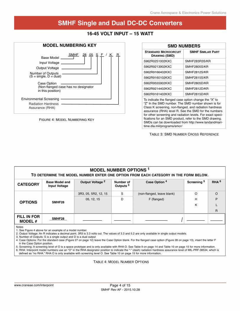
Model nuMbering key
SMHF 28 05 S F / K RBase Model
Input VoltageOutput Voltage
Environmental Screening
Number of Outputs(S = single, D = dual)
Radiation HardnessAssurance (RHA)
Case Option(Non-flanged case has no designator in this position)
sMd nuMbersStandard Microcircuit
drawing (SMd)SMHF SiMilar Part
5962R0251002KXC SMHF283R3S/KR5962R9213902KXC SMHF2805S/KR5962R9166402KXC SMHF2812S/KR5962R9160102KXC SMHF2815S/KR5962R9555902KXC SMHF2805D/KR5962R9214402KXC SMHF2812D/KR5962R9161402KXC SMHF2815D/KRTo indicate the flanged case option change the “X” to “Z” In the SMD number. The SMD number shown is for Class K screening, non-flanged, and radiation hardness assurance (RHA) level R. See the SMD for the numbers for other screening and radiation levels. For exact speci-fications for an SMD product, refer to the SMD drawing. SMDs can be downloaded from http://www.landandmari-time.dla.mil/programs/smcr/
Model nuMber options 1to deterMine tHe Model nuMber enter one oPtion FroM eacH category in tHe ForM below.
category base Model and input Voltage
output Voltage 2 number of outputs 3
case option 4 screening 5 rHa 6
options sMHF28
3R3, 05, 5R2, 12, 15 S (non-flanged, leave blank) O O05, 12, 15 D F (flanged) H P
K L
R
Fill in For Model #
sMHF28__________ / _______ Notes1. See Figure 4 above for an example of a model number. 2. Output Voltage: An R indicates a decimal point. 3R3 is 3.3 volts out. The values of 3.3 and 5.2 are only available in single output models. 3. Number of Outputs: S is a single output and D is a dual output4. Case Options: For the standard case (Figure 27 on page 12) leave the Case Option blank. For the flanged case option (Figure 28 on page 13), insert the letter F
in the Case Option position. 5. Screening: A screening level of O is a space prototype and is only available with RHA O. See Table 9 on page 14 and Table 10 on page 15 for more information.6. RHA: Interpoint model numbers use an “O” in the RHA designator position to indicate the “-” (dash) radiation hardness assurance level of MIL-PRF-38534, which is
defined as “no RHA.” RHA O is only available with screening level O. See Table 10 on page 15 for more information.
taBle 3: SMD nuMBer croSS reFerence
taBle 4: MoDel nuMBer optionS
Figure 4: MoDel nuMBering key
sMHF single and dual dc-dc converters
Page 4 of 15
16-45 Volt input – 15 Watt
www.craneae.com/interpointSMHF Rev AF - 2015.10.28
Crane Aerospace & Electronics Power Solutions

SMHF SERIES ALL MODELSPARAMETER CONDITIONS MIN TYP MAX UNITSLEAD SOLDERINg TEMPERATURE 1 10 SECONDS MAX. — — 300 °CSTORAgE TEMPERATURE 1 -65 — +150 °C
CASE OPERATINg FULL POWER -55 — +125 °CTEMPERATURE ABSOLUTE 1 -55 — +135DERATINg OUTPUT POWER/CURRENT 1 LINEARLY From 100% at 125°C to 0% at 135°C
ESD RATINg 1 MIL-STD-883 METHOD 3015 1000-1999 V MIL-PRF-38534, 3.9.5.8.2 CLASS 1C
ISOLATION: INPUT TO OUTPUT OR ANY @ 500 VDC AT 25°C 100 — — Megohms PIN TO CASE EXCEPT CASE PIN
UNDERVOLTAgE LOCKOUT 1 VIN — 14 — V
INPUT TO OUTPUT CAPACITANCE 1 — 60 — pF
CURRENT LIMIT 1, 2 % OF FULL LOAD — 140 — %
AUDIO REJECTION 1 — 50 — dB
CONVERSION FREQUENCY FREE RUN-55°C TO +125°C 480 550 620 kHz
SYNCHRONIZATION INPUT FREQUENCY 500 — 600 kHz
DUTY CYCLE 1 40 — 60 %
ACTIVE LOW — — 0.8 VACTIVE HIgH 1 4.5 — 5.0
REFERENCED TO INPUT COMMONIF NOT USED CONNECT TO INPUT COMMON
INHIBIT ACTIVE LOW (OUTPUT DISABLED) INHIBIT PIN PULLED LOW — — 0.8 V
Do not apply a voltage to the inhibit pin INHIBIT PIN SOURCE CURRENT 1 — — 5 mA
REFERENCED TO INPUT COMMONINHIBIT ACTIVE HIgH (OUTPUT ENABLED)Do not apply a voltage to the inhibit pin INHIBIT PIN CONDITION OPEN COLLECTOR OR
UNCONNECTEDOPEN INHIBIT PIN VOLTAgE 1 7.5 — 12 V
Notes1. guaranteed by characterization test and/or analysis. Not a production test.2. Dual outputs: The over-current limit will trigger when the sum of the currents from both outputs reaches 140% (typical value) of the
maximum rated “total” current of both outputs.
taBle 5: operating conDitionS - all MoDelS, 25°c caSe, 28 vin, unleSS otHerwiSe SpeciFieD
For mean time between failures (MTBF) contact Applications [email protected] +1 425-882-3100 option 7
sMHF single and dual dc-dc converters
Page 5 of 15
16-45 Volt input – 15 Watt
www.craneae.com/interpointSMHF Rev AF - 2015.10.28
Crane Aerospace & Electronics Power Solutions

Notes1. guaranteed by characterization test and/or analysis. Not a production test.2. Indefinite short circuit protection not guaranteed above 125°C (case)3. Step transition time >10 µs. 4. Recovery time is measured from application of the transient to the point at which Vout is within regulation.
5. Step transition time 100 µs ±20%.6. Tested on release from inhibit.
SINgLE OUTPUT MODELS SMHF283R3S SMHF2805S SMHF285R2SUNITSPARAMETER CONDITIONS MIN TYP MAX MIN TYP MAX MIN TYP MAX
OUTPUT VOLTAgE 3.20 3.30 3.40 4.85 5.00 5.15 5.05 5.20 5.35 VOUTPUT CURRENT VIN = 16 TO 45 V — — 2.4 — — 2.4 — — 2.4 AOUTPUT POWER VIN = 16 TO 45 V 0 — 8 0 — 12 0 — 12.5 WOUTPUT RIPPLE TC = 25°C — 5 30 — 5 30 — 5 30 mV p-p10 kHz - 2 MHz TC = -55°C TO +125°C — 5 30 — 5 30 — 5 30LINE REgULATION VIN = 16 TO 45 V — 1 10 — 1 10 — 1 10 mVLOAD REgULATION NO LOAD TO FULL — 20 50 — 20 50 — 20 50 mVINPUT VOLTAgE CONTINUOUS 16 28 45 16 28 45 16 28 45 V
NO LOAD TO FULL TRANSIENT 50 ms 1 0 — 50 0 — 50 0 — 50 V
INPUT CURRENT NO LOAD — 25 50 — 25 40 — 25 40 mAINHIBITED — 6 10 — 6 10 — 6 10
INPUT RIPPLE CURRENT 10 kHz - 10 MHz — — 120 — — 120 — — 120 mA p-pEFFICIENCY TC = 25°C 68 71 — 73 76 — 72 78 — %
TC = -55°C TO +125°C 65 — — 70 — — 70 — —LOAD FAULT 2 POWER DISSIPATION — 5 8 — 3.5 8 — 3.5 8 WSHORT CIRCUIT RECOVERY 1 — 7.5 30 — 7.5 30 — 7.5 30 msSTEP LOAD RESPONSE 3, 4 TRANSIENT — 150 400 — 150 400 — 150 400 mV pk50% - 100% - 50% RECOVERY — 150 300 — 150 300 — 150 300 µsSTEP LINE RESPONSE 1, 4, 5 TRANSIENT — 550 800 — 550 800 — — 800 mV pk16 - 40 - 16 V RECOVERY — 200 500 — 200 500 — — 600 µsSTEP LINE RESPONSE 1, 4, 5 TRANSIENT — 70 — — 110 — — 110 — mV pk22 - 32 - 22 V RECOVERY — 200 — — 180 — — 180 — µsSTEP LINE RESPONSE 1, 4, 5 TRANSIENT — 100 — — 160 — — 160 — mV pk36 - 45 - 36 V RECOVERY — 250 — — 180 — — 180 — µsSTARTUP 6 DELAY — 10 25 — 10 25 — 10 25 ms
OVERSHOOT 1 — 15 50 — 15 50 — 15 50 mV pkCAPACITIVE LOAD TC = 25°C — — 300 — — 300 — — 300 µF
taBle 6: electrical cHaracteriSticS: -55°c to +125°c caSe, 28 vin, 100% loaD, unleSS otHerwiSe SpeciFieD.
sMHF single and dual dc-dc converters
Page 6 of 15
16-45 Volt input – 15 Watt
www.craneae.com/interpointSMHF Rev AF - 2015.10.28
Crane Aerospace & Electronics Power Solutions

SINgLE OUTPUT MODELS SMHF2812S SMHF2815SUNITSPARAMETER CONDITIONS MIN TYP MAX MIN TYP MAX
OUTPUT VOLTAgE 11.76 12.00 12.24 14.70 15.00 15.30 VOUTPUT CURRENT VIN = 16 TO 45 V — — 1.25 — — 1.00 AOUTPUT POWER VIN = 16 TO 45 V 0 — 15 0 — 15 WOUTPUT RIPPLE TC = 25°C — 15 40 — 10 40 mV p-p10 kHz - 2 MHz TC = -55°C TO +125°C — 15 40 — 10 40LINE REgULATION VIN = 16 TO 45 V — 5 20 — 8 30 mVLOAD REgULATION NO LOAD TO FULL — 20 50 — 20 50 mVINPUT VOLTAgE CONTINUOUS 16 28 45 16 28 45 V
NO LOAD TO FULL TRANSIENT 50 ms 1 0 — 50 0 — 50 V
INPUT CURRENT NO LOAD — 25 55 — 25 62 mAINHIBITED — 5 10 — 5 10
INPUT RIPPLE CURRENT 10 kHz - 10 MHz — — 120 — — 120 mA p-pEFFICIENCY TC = 25°C 76 79 — 78 78 — %
TC = -55°C TO +125°C 72 — — 74 — —LOAD FAULT 2 POWER DISSIPATION — 3.5 8 — 3.5 8 W
SHORT CIRCUIT RECOVERY 1 — 7.5 30 — 7.5 30 msSTEP LOAD RESPONSE 3, 4 TRANSIENT — 150 500 — 200 500 mV pk
50% - 100% - 50% RECOVERY — 50 300 — 50 300 µsSTEP LINE RESPONSE 1, 4, 5 TRANSIENT — 550 800 — 550 800 mV pk16 - 40 - 16 V RECOVERY — 300 700 — 300 700 µsSTEP LINE RESPONSE 1, 4, 5 TRANSIENT — 250 — — 250 — mV pk22 - 32 - 22 V RECOVERY — 210 — — 210 — µsSTEP LINE RESPONSE 1, 4, 5 TRANSIENT — 350 — — 350 — mV pk36 - 45 - 36 V RECOVERY — 300 — — 300 — µsSTARTUP 6 DELAY — 10 25 — 10 25 ms
OVERSHOOT 1 — 25 50 — 25 50 mV pkCAPACITIVE LOAD TC = 25°C — — 100 — — 100 µF
taBle 7: electrical cHaracteriSticS: -55°c to +125°c caSe, 28 vin, 100% loaD, unleSS otHerwiSe SpeciFieD.
Notes1. guaranteed by characterization test and/or analysis. Not a production test.2. Indefinite short circuit protection not guaranteed above 125°C (case)3. Step transition time >10 µs. 4. Recovery time is measured from application of the transient to the point at which Vout is within regulation.
5. Step transition time 100 µs ±20%.6. Tested on release from inhibit.
sMHF single and dual dc-dc converters
Page 7 of 15
16-45 Volt input – 15 Watt
www.craneae.com/interpointSMHF Rev AF - 2015.10.28
Crane Aerospace & Electronics Power Solutions

DUAL OUTPUT MODELS SMHF2805D SMHF2812D SMHF2815DUNITSPARAMETER CONDITIONS MIN TYP MAX MIN TYP MAX MIN TYP MAX
OUTPUT VOLTAgE +VOUT 4.85 5.00 5.15 11.76 12.00 12.24 14.70 15.00 15.30 V-VOUT 4.82 5.00 5.18 11.70 12.00 12.30 14.63 15.00 15.38
OUTPUT CURRENT 2 EITHER OUTPUT — ±1.2 1.68 — ±0.625 0.875 — ±0.5 0.7 AVIN = 16 TO 45 V TOTAL — — 2.4 — — 1.25 — — 1.0OUTPUT POWER 2 EITHER OUTPUT — ±6 8.4 — — 10.5 — — 10.5 WVIN = 16 TO 45 V TOTAL — — 12 — — 15 — — 15OUTPUT RIPPLE TC = 25°C — 30 95 — 30 95 — 30 95 mV p-p± VOUT, 10 kHz - 2 MHz TC = -55°C TO +125°C — 30 95 — 30 95 — 30 95LINE REgULATION 3 +VOUT — 2 10 — 2 18 — 2 18 mVVIN = 16 TO 45 V -VOUT — 10 100 — 10 100 — 10 100LOAD REgULATION 3 +VOUT — 5 25 — 5 25 — 5 25 mVNO LOAD TO FULL -VOUT — 80 150 — 60 150 — 40 150CROSS REgULATION 4 EFFECT ON -VOUT — 6 7.5 — 3 6 — 3 6 %INPUT VOLTAgE CONTINUOUS 16 28 45 16 28 45 16 28 45 VNO LOAD TO FULL TRANSIENT 50 ms 1 — — 50 — — 50 — — 50 VINPUT CURRENT NO LOAD — 25 50 — 30 50 — 30 50 mA
INHIBITED — 6 10 — 6 10 — 6 10INPUT RIPPLE CURRENT 10 kHz - 10 MHz — 60 120 — 55 120 — 55 120 mA p-pEFFICIENCY TC = 25°C 75 77 — 76 80 — 76 82 — %
TC = -55°C TO +125°C 72 — — 74 — — 74 — —LOAD FAULT 5 POWER DISSIPATION — 3 6 — 3 6 — 3 6 WSHORT CIRCUIT RECOVERY 1 — 6 30 — 6 50 — 6 50 msSTEP LOAD RESPONSE 6, 7, 8 TRANSIENT — ±200 ±500 — ±300 ±600 — ±300 ±600 mV pk50% - 100% - 50% Bal Loads RECOVERY — 90 400 — 90 400 — 90 400 µsSTEP LINE RESPONSE 1, 6, 9 TRANSIENT — ±500 ±800 — ±500 ±750 — ±550 ±750 mV pk± VOUT, 16 - 40 - 16 V RECOVERY — 200 700 — 300 900 — 300 900 µsSTEP LINE RESPONSE 1, 6, 9 TRANSIENT — ±125 — — ±160 — — ±160 — mV pk± VOUT, 22 - 32 - 22 V RECOVERY — 200 — — 160 — — 160 — µsSTEP LINE RESPONSE 1, 6, 9 TRANSIENT — ±200 — — ±250 — — ±250 — mV pk± VOUT, 36 - 45 - 36 V RECOVERY — 160 — — 200 — — 200 — µsSTARTUP 10 DELAY — 12 25 — 10 20 — 10 20 ms
OVERSHOOT 1 0 100 500 0 100 500 0 100 500 mV pkCAPACITIVE LOAD 11 TC = 25°C — — 47 — — 10 — — 10 µF
taBle 8: electrical cHaracteriSticS: -55°c to +125°c caSe, 28 vin, 100% loaD, unleSS otHerwiSe SpeciFieD.
Notes1. guaranteed by characterization test and/or analysis. Not a production test.2. Up to 70% of the total output power is available from either output providing the
opposite output is simultaneously carrying 30% of the total output power. Each output must carry a minimum of 30% of the total output power in order to maintain regulation on the negative output.
3. Balanced loads.4. Effect on –VOUT for the following conditions, percentages are of total power: +PO = 50%, –PO = 10%; +PO = 10%, –PO = 50%
+PO = 70%, –PO = 30%; +PO = 30%, –PO = 70% All conditions are referenced to balanced loads of 50%/50%.
5. Indefinite short circuit protection not guaranteed above 125°C (case)6. Recovery time is measured from application of the transient to point at which
VOUT is within regulation.7. Response of either output with the opposite output held at half of the total output
power.8. Step transition time >10 µs.9. Step transition time 100 µs ±20%.10. Tested on release from inhibit. 11. Applies to each output.
sMHF single and dual dc-dc converters
Page 8 of 15
16-45 Volt input – 15 Watt
www.craneae.com/interpointSMHF Rev AF - 2015.10.28
Crane Aerospace & Electronics Power Solutions

Typical performance ploTs: 25°c case, 28 Vin, 100% load, free run, unless oTherwise specified.These are examples for reference only and are not guaranteed specifications.
–1000.1 1 10 100
–90
–80
–70
–60
–50
–40
–20
–10
0
–30
SMHF Series Single Audio Rejection
Audi
o R
ejec
tion
(dB)
Frequency (kHz), 28 VIN
MIL-STD-461 C CE03 LIMIT
NARROWBAND90
70
50
30
10
.015 0.1 1 10 50
Figure 5
SMHF2805S, unfiltered, Representative of the SMHF Series of DC-DC Converters
Emis
sion
Lev
el (d
B µA
)
Frequency (MHz), 28 VIN
NARROWBAND90
70
50
30
10
.015 0.1 1 10 50
MIL-STD-461 C CE03 LIMIT
Figure 6
SMHF2805S with Interpoint SFMC28-461 EMI Filter, Representative of the SMHF Series of DC-DC Converters
Emis
sion
Lev
el (d
B µV
)
Frequency (MHz), 28 VIN
Figure 7 Figure 8 Figure 9
100 µs/div
1 μs/div
2 m
A/di
v.
1 μs/div
2 m
V/di
v.
Representative of SMHF Series IIN Ripple
Representative of SMHF Series VOUT Ripple
2 m
A/di
v
10 m
V/di
v
1 µs/div 1 µs/div
+Vout
-Vout
sMHF single and dual dc-dc converters
Page 9 of 15
16-45 Volt input – 15 Watt
www.craneae.com/interpointSMHF Rev AF - 2015.10.28
Crane Aerospace & Electronics Power Solutions

Typical performance ploTs: 25°c case, 28 Vin, 100% load, free run, unless oTherwise specified.These are examples for reference only and are not guaranteed specifications.
100 μs/div16-45 Vin
200
mV/
div.
20 V
/div.
100 μs/div45-16 Vin
200
mV/
div.
20 V
/div.
100 μs/div50 - 100 -50%
100
mV/
div.
SMHF2805S Representative of Single Output Line Transient
SMHF2805S Representative of Single Output Line Transient
SMHF2805S Representative of Single Output Load Transient
SMHF2805S Representative of Single Output Low Line Dropout vs. Load
200
mV/
div
Inpu
t Vol
tage
(Vol
ts)
200
mV/
div
200
mV/
div
20 V
/div
20 V
/div
100 µs/div 100 µs/div 100 µs/div
Output Power (Watts)
VIN 16 to 45 V, full resistive load VIN 45 to 16 V, full resistive load 50 - 100 - 50% Load
50 mV Drop4 ms/divFull Load
SMHF2805S Turn-On
2 V/
div.
20 V
/div.
SMHF2805S Representative of Single Output Turn-On Delay
2 V/
div
20 V
/div
4 ms/divFull resistive load
SMHF2805S Efficiency
Effic
ienc
y (%
)
Output Power (Watts)16 VIN 28 VIN 45 VIN
35
45
55
65
75
85
1.2 3 6 9 12
Effic
ienc
y (%
)
Output Power (Watts) 16V 28V 45V
SMHF2805S SMHF2812S Efficiency
Effic
ienc
y (%
)
Output Power (Watts)
35
45
55
65
75
85
1.5 3.75 7.5 11.25 15
Effic
ienc
y (%
)
Output Power (Watts) 16V 28V 45V
SMHF2812S SMHF2815S Efficiency
Effic
ienc
y (%
)
Output Power (Watts)
35
45
55
65
75
85
1.5 3.75 7.5 11.25 15
Effii
cien
cy (%
)
Output Power (Watts) 16V 28V 45V
SMHF2815S
OUTPUT POWER (Watts)50 mV DROP
LOW LINE DROPOUT VS. LOAD
INPU
T VO
LTAG
E (V
olts
)
10 11 12 13 14 15
14
15
16
SMHF2812S&DSMHF2815S&D
SMHF2805S&D
13
12
Figure 10
Figure 13 Figure 14
Figure 15 Figure 16 Figure 17
Figure 11 Figure 12
16 VIN 28 VIN 45 VIN 16 VIN 28 VIN 45 VIN
sMHF single and dual dc-dc converters
Page 10 of 15
16-45 Volt input – 15 Watt
www.craneae.com/interpointSMHF Rev AF - 2015.10.28
Crane Aerospace & Electronics Power Solutions

Typical performance ploTs: 25°c case, 28 Vin, 100% load, free run, unless oTherwise specified.These are examples for reference only and are not guaranteed specifications.
100 μs/div16-45 VIN
500
mV/
div.
20 V
/div.
100 μs/div45-16 Vin
500
mV/
div.
20 V
/div.
2.5 ms/div50 - 100 - 50%
200
mV/
div.
25 ms/divFull Load
SMHF2815D Turn-On
5 V/
div.
20 V
/div.
SMHF2815D Representative of Dual Output Line Transient
SMHF2815D Representative of Dual Output Line Transient
SMHF2815D Representative of Dual Output Load Transient
200
mV/
div
200
mV/
div
200
mV/
div
20 V
/div
20 V
/div
100 µs/div
+VOUT+VOUT
+VOUT
+VOUT
-VOUT-VOUT
-VOUT
-VOUT
100 µs/div 100 µs/divVIN 16 to 45 V, full resistive load VIN 16 to 45 V, full resistive load 50 - 100 - 50% Load
SMHF2815D Representative of Dual Output Turn-On Delay
|2| V
/div
20 V
/div
4 ms/divFull resistive load
SMHF2805D Efficiency
Effic
ienc
y (%
)
Output Power (Watts)
35
45
55
65
75
85
95
1.2 3 6 9 12
Effic
ienc
y (%
)
Output Power (Watts) 16V 28V 45V
SMHF2805D SMHF2812D Efficiency
Effic
ienc
y (%
)
Output Power (Watts)
35
45
55
65
75
85
95
1.5 3.75 7.5 11.25 15
Effic
ienc
y (%
)
Output Power (Watts) 16V 28V 45V
SMHF2812D SMHF2815D Efficiency
Effic
ienc
y (%
)
Output Power (Watts)
35
45
55
65
75
85
95
1.5 3.75 7.5 11.25 15
Effic
ienc
y (%
)
Output Power (Watts) 16V 28V 45V
SMHF2815D
POSITIVE OUTPUT LOAD (% OF TOTAL LOAD)-VOUT WITH SHIFT IN LOAD BALANCE
CROSS REGULATION
-V O
UT
VOLT
AGE
CH
ANG
E (%
)
-101000 20 40 60 80
-5
0
5
10
2812D2815D
2805D
OUTPUT LOAD (%)COND. A: 50% LOAD +V; 50% to 10% -VCOND. B: 50% LOAD -V; 50% to 10% +V
SMHF2805D/SMHF2812D/SMHF2815DCROSS REGULATION
-VO
UT
VOLT
AGE
CH
ANG
E (%
)
-10
0
10
10 20 30 40 50
-8
-6
-4
-2
2
4
6
8
2815D
2812D
2812D
COND B
COND A
2805D
2805D
SMHF Dual Cross Regulation SMHF Dual Cross Regulation
-VO
UT
Volta
ge C
hang
e (%
)
-VO
UT
Volta
ge C
hang
e (%
)
Positive Output Load (% of Total Load) Output Load (%)-VOUT with Shift in Load Balance Condition A: +V 50% Load; -V 50% to 10% Load
Condition B: -V 50% Load; +V 50% to 10% Load
Figure 18 Figure 19 Figure 20
Figure 21 Figure 22 Figure 23
Figure 26 Figure 24 Figure 25
16 VIN 28 VIN 45 VIN 16 VIN 28 VIN 45 VIN 16 VIN 28 VIN 45 VIN
sMHF single and dual dc-dc converters
Page 11 of 15
16-45 Volt input – 15 Watt
www.craneae.com/interpointSMHF Rev AF - 2015.10.28
Crane Aerospace & Electronics Power Solutions
0.00
0
0.20
5 (5
.21)
0.50
5 (1
2.83
)
0.70
5 (1
7.91
)
0.90
5 (2
2.99
)
1.10
5 (2
8.07
)
0.33
0 m
ax.
(8.3
8)
0.00
0
0.25
(6.3
5)0.000
0.160 (4.06)
0.960 (24.38)1 2 3 4 5
0.030 dia.(0.76)
8 7 6
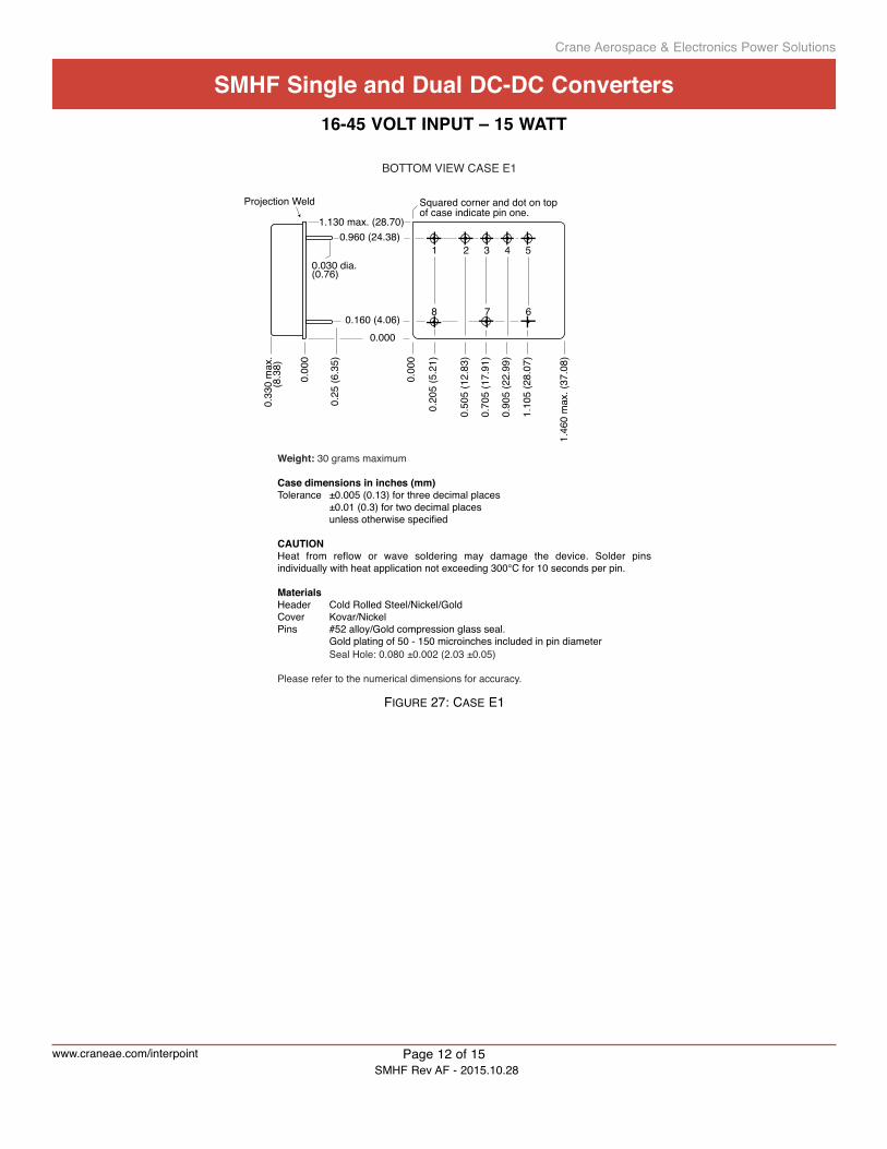
BOTTOM VIEW CASE E1
Projection Weld Squared corner and dot on topof case indicate pin one.
1.130 max. (28.70)
1.46
0 m
ax. (
37.0
8)
Weight: 30 grams maximum
Case dimensions in inches (mm)Tolerance ±0.005 (0.13) for three decimal places ±0.01 (0.3) for two decimal places unless otherwise specified
CAUTIONHeat from reflow or wave soldering may damage the device. Solder pins individually with heat application not exceeding 300°C for 10 seconds per pin.
MaterialsHeader Cold Rolled Steel/Nickel/GoldCover Kovar/NickelPins #52 alloy/Gold compression glass seal. Gold plating of 50 - 150 microinches included in pin diameter Seal Hole: 0.080 ±0.002 (2.03 ±0.05)
Please refer to the numerical dimensions for accuracy.
Case E1, Rev F, 2013.11.15Figure 27: caSe e1
Page 12 of 15
sMHF single and dual dc-dc converters16-45 Volt input – 15 Watt
www.craneae.com/interpointSMHF Rev AF - 2015.10.28
Crane Aerospace & Electronics Power Solutions

1.59
0 (4
0.39
)
2 x Dia 0.128 ±0.002 (3.25 ±0.05)
Flanged cases: Designator "F" required in Case Option position of model numberBOTTOM VIEW CASE G1
0.20
5 (5
.21)
0.50
5 (1
2.83
)
0.70
5 (1
7.91
)
0.90
5 (2
2.99
)
1.10
5 (2
8.07
)
1 2 3 4 5
8 7 6
0.14
0 (3
.56)
0.560(14.22)
Squared corner and dot on topof case indicate pin one.
1.130 max. (28.70)
0.030 dia.(0.76)
0.33
0 m
ax.
(8.3
8)
0.00
0
0.25
(6.3
5)
Projection Weld
(2.005 max (50.93))
0.960(24.38)
0.000
0.160(4.06)
Weight: 30 grams maximum
Case dimensions in inches (mm)Tolerance ±0.005 (0.13) for three decimal places ±0.01 (0.3) for two decimal places unless otherwise specified
CAUTIONHeat from reflow or wave soldering may damage the device. Solder pins individually with heat application not exceeding 300°C for 10 seconds per pin.
MaterialsHeader Cold Rolled Steel/Nickel/GoldCover Kovar/NickelPins #52 alloy/Gold compression glass seal Gold plating of 50 - 150 microinches included in pin diameter Seal Hole: 0.080 ±0.002 (2.03 ±0.05)
Please refer to the numerical dimensions for accuracy.
Case G1, Rev G, 2014.09.11
2 x R 0.130 (3.30)
Flange thickness: 0.047 (1.19)
(0.0
00)
(1.4
50 (3
6.83
))
Base Plate Detail, Edge View
top of header
Figure 28: caSe g1
Page 13 of 15
sMHF single and dual dc-dc converters16-45 Volt input – 15 Watt
www.craneae.com/interpointSMHF Rev AF - 2015.10.28
Crane Aerospace & Electronics Power Solutions

Table is for reference only. See individual Series' datasheets for specific screening.
TABLE 3: ELEMENT EVALUATION SPACE DC-DC CONVERTERS PROTOTYPE, CLASS H AND CLASS K
ELEMENT EVALUATION SPACE DC-DC CONVERTERS PROTOTYPE, CLASS H AND CLASS K
NON-QML 1 QML
PROTOTYPE CLASS H CLASS K
COMPONENT-LEVEL TEST PERFORMED
/O /H /KM/S 2 M/S 2 P 3 M/S 2 P 3
Element Electrical n n n n n
Visual n n n n
Internal Visual n n
Temperature Cycling n n
Constant Acceleration n n
Interim Electrical n
Burn-in n
Post Burn-in Electrical n
Steady State Life n
Voltage Conditioning Aging n
Visual Inspection n
Final Electrical n n n n
Wire Bond Evaluation n n n n
SEM n
Notes1. Non-QML products may not meet all of the requirements of MIL-PRF-38534. 2. M/S = Active components (microcircuit and semiconductor die)3. P = Passive components, Class H and K element evaluation. Not applicable to space prototype (“O”) element
evaluation.
Definitions:Element Evaluation: Component testing/screening per MIL-STD-883 as determined by MIL-PRF-38534SEM: scanning electron microscopy
Crane Aerospace & Electronics Power Solutions
Quality assurance and certificationapplication note
Page 5 of 13APP-009 Rev AF - 2015.10.21
www.craneae.com/interpoint
taBle 9: eleMent evaluation–Dc-Dc converterS prototype, claSS H anD claSS k
sMHF single and dual dc-dc converters
Page 14 of 15
16-45 Volt input – 15 Watt
www.craneae.com/interpointSMHF Rev AF - 2015.10.28
Crane Aerospace & Electronics Power Solutions

taBle 10: environMental Screening anD rHa–Dc-Dc converterS prototype, claSS H anD claSS k, rHa p, l or r
Table is for reference only. See individual Series' datasheets for specific screening.
TABLE 4: ENVIRONMENTAL SCREENING SPACE DC-DC CONVERTERS PROTOTYPE, CLASS H AND CLASS K, RHA P, L AND R
ENVIRONMENTAL SCREENING SPACE DC-DC CONVERTERS PROTOTYPE, CLASS H AND CLASS K, RHA 1 P, L AND R
NON-QML 2 QML 3
PROTOTYPE CLASS H CLASS KTEST PERFORMED /OO 4 /HP /HL /HR /KP /KL /KRnon-destruct wire bond pull, Method 2023 n 5 n 5 n 5 n n n
pre-cap inspection, Method 2017, 2032 n n n n n n n
temperature cycle (10 times) (Qual 100 times)
Method 1010, Cond. C, -65°C to +150°C, ambient n n n n n n n
constant acceleration Method 2001, 3000 g (Qual 5000 g) n n n n n n n
pind, test Method 2020, cond. a n 5 n 5 n 5 n n n
pre burn-in test, group a, subgroups 1 and 4 n n 5 n 5 n 5 n n n
burn-in Method 1015, +125°c case, typical 6
96 hours n
160 hours n n n
2 x 160 hours (includes mid-BI test) n n n
Final electrical test, Mil-prF-38534, group a, Subgroups 1 and 4: +25°C case n
Subgroups 1 through 6, -55°C, +25°C, +125°C case n n n n n n
Hermeticity test, Method 1014gross Leak, Cond. B2, Kr85 n n n
gross Leak, Cond. C1, fluorocarbon n n n n
Fine Leak, Cond. B1, Kr85 n n n
Fine Leak, Cond. A2, helium n n n n
radiography, Method 2012 n n n
post radiography electrical test, +25°c case n 5 n 5 n 5
Final visual inspection, Method 2009 n n n n n n n
rHa p: 30 krad(si) total dose 1, 7, 8 n n
rHa l: 50 krad(si) total dose 1, 7, 8 n n
rHa r: 100 krad(si) total dose 1, 7, 8 n n
see, let 86 MeV cm2/mg 1, 9 n n n n n n
Test methods are referenced to MIL-STD-883 as determined by MIL-PRF-38534.Notes1. Our Redmond facility has a DLA approved RHA plan for Interpoint power
products. Our SMD products with RHA “P”, “L” or “R” code meet DLA requirements.
2. Non-QML prototype products may not meet all of the requirements of MIL-PRF-38534.
3. All processes are QML qualified and performed by certified operators.4. “O” in the RHA designator position in Interpoint model numbers indicates DLA
RHA “-” defined as no RHA.
5. Not required by DLA but performed to assure product quality.6. Burn-in temperature designed to bring the case temperature to +125°C minimum.
Burn-in is a powered test. 7. High dose rate test.8. Low dose rate test.9. No destructive events or SEL.
Page 15 of 15
sMHF single and dual dc-dc converters16-45 Volt input – 15 Watt
SMHF Single and Dual, SMHF Rev AF - 2015.10.28. This revision supersedes all previous releases. All technical information is believed to be accurate, but no responsibility is assumed for errors or omissions. Crane Electronics, Inc. reserves the right to make changes in products or specifications without notice. Interpoint is a registered trademark of Crane Co. SMHF Series is a trademark of Crane Electronics, Inc. Copyright © 1999 - 2015 Crane Electronics, Inc. All rights reserved. www.craneae.com/interpoint
Crane Aerospace & Electronics Power Solutions