MODBUS RTU - kampmann.de · KaControl – MODBUS RTU 1 Bestimmungsgemäße Verwendung
Instruction Manual January 2004
MODBUS RTUsmartlinx interface module

© Siemens Milltronics Process Instruments Inc. 2004
Safety Guidelines
Warning notices must be observed to ensure personal safety as well as that of others, and toprotect the product and the connected equipment. These warning notices are accompaniedby a clarification of the level of caution to be observed.
Qualified Personnel
This device/system may only be set up and operated in conjunction with this manual.Qualified personnel are only authorized to install and operate this equipment in accordancewith established safety practices and standards.
Warning: This product can only function properly and safely if it is correctly transported,stored, installed, set up, operated, and maintained.
Note: Always use product in accordance with specifications.
Copyright Siemens Milltronics ProcessInstruments Inc. 2004. All Rights Reserved
Disclaimer of Liability
This document is available in bound version and inelectronic version. We encourage users topurchase authorized bound manuals, or to viewelectronic versions as designed and authored bySiemens Milltronics Process Instruments Inc.Siemens Milltronics Process Instruments Inc. willnot be responsible for the contents of partial orwhole reproductions of either bound or electronicversions.
While we have verified the contents ofthis manual for agreement with theinstrumentation described, variationsremain possible. Thus we cannotguarantee full agreement. Thecontents of this manual are regularlyreviewed and corrections are includedin subsequent editions. We welcomeall suggestions for improvement.
Technical data subject to change.
MILLTRONICS®is a registered trademark of Siemens Milltronics Process Instruments Inc.
Contact SMPI Technical Publications at the following address:
Technical PublicationsSiemens Milltronics Process Instruments Inc.1954 Technology Drive, P.O. Box 4225Peterborough, Ontario, Canada, K9J 7B1Email: [email protected]
For the library of SMPI instruction manuals, visit our Web site: www.siemens-milltronics.com

i
Table of Contents
About this Module .......................................................................................................................................1
Typical Modbus RTU RS-485 System .................................................................................................1Typical Modbus RTU RS-232 System .................................................................................................2
About this Manual .......................................................................................................................................3
Specifications ...............................................................................................................................................4
Installation ......................................................................................................................................................5
Compatibility .............................................................................................................................................5Module Outline ........................................................................................................................................5Termination Switch .................................................................................................................................6Port Configuration ...................................................................................................................................6Reserved Switch ......................................................................................................................................6Cable Connection ....................................................................................................................................7
Operation .........................................................................................................................................................9
Status LEDs ...............................................................................................................................................9Initialization LED ......................................................................................................................................9
Communications Setup ..........................................................................................................................10
General .....................................................................................................................................................10Specific Parameters .............................................................................................................................10
Application Layer ......................................................................................................................................12
Parameter Indexes ................................................................................................................................12How Modbus RTU Works ....................................................................................................................13Register Mapping ..................................................................................................................................14Data Access Methods ..........................................................................................................................15Register Map Level Products .........................................................................................................17Data Types ...............................................................................................................................................21Modbus RTU Error Codes ...................................................................................................................24
Troubleshooting ..........................................................................................................................................25
Generally .................................................................................................................................................25Specifically ..............................................................................................................................................25
Wiring Guidelines .....................................................................................................................................26

ii

7ML19981BF01 SmartLinx Modbus RTU INSTRUCTION MANUAL Page 1
mm
mm
m
About this M
odule
About this Module
The Milltronics SmartLinx®Modbus® RTU Module plugs into a compatible Milltronics instrument to allow connection to any Modbus RTU master controller.
Modbus RTU is an industry standard protocol that is supported by many different instruments. A brief description of the protocol and the Milltronics memory map are outlined in Modbus RTU Protocol section of this manual (see page 20).
Only those instruments which support the SmartLinx Modbus RTU module can use this card. See Specifications on page 5 for a list of compatible instruments.
Typical Modbus RTU RS-485 System
®. Modbus is a registered trademark of Schneider Electric.
m A5
9
C
P P
6
0
7 8
1 2 3 4

Page 2 SmartLinx Modbus RTU INSTRUCTION MANUAL 7ML19981BF01
mm
mm
m
Abo
ut th
is M
odul
e
Typical Modbus RTU RS-232 System
m A5
9
C
P P
6
0
7 8
1 2 3 4

7ML19981BF01 SmartLinx Modbus RTU INSTRUCTION MANUAL Page 3
mm
mm
m
About this M
anual
About this Manual
This manual is intended to provide the user with the information required to successfully install and connect a Milltronics SmartLinx Modbus RTU module and set it up for communication within a Modbus RTU network.
This manual is targeted to a technical audience in the industrial communications field with a sound working knowledge of Modbus RTU.
Modbus RTU is an industry standard protocol owned by Schneider Electric and is used throughout process control industries for communication between instruments, including those manufactured by Milltronics, and controllers, such as PLCs and PCs.
A brief description of Modbus RTU is given in this manual. For a full description of the Modbus RTU protocol, contact Schneider Electric or visit their website at www.modicon.com.
If you have any questions, comments, or suggestions about the manual contents, please email us at [email protected].
For the complete library of Siemens Milltronics manuals, go to www.siemens-milltronics.com.
Note: Milltronics does not own the Modbus RTU protocol. All information regarding that protocol is subject to change without notice.

Page 4 SmartLinx Modbus RTU INSTRUCTION MANUAL 7ML19981BF01
mm
mm
m
Spec
ifica
tions
Specifications
Application: compatible with Modbus RTU masters that use function codes 03, 06, 16
Compatible Instruments: AiRanger XPL Plus/SITRANS LU 10 AiRanger DPL Plus/SITRANS LU 02 AiRanger SPL/SITRANS LU 01 CraneRanger InterRanger DPS 300
Communication Settings baud rate: 1200, 2400, 4800, 9600, 19200, 38400 bps parity: none, odd or even stop bit: 1 or 2 data bits: 8 hardware flow control: none
Connection: 6-position screw terminal
Termination: RS-485 switch selectable, open or 110 Ω internal
Cable: for RS-232 connection use cable consistent with the RS-232 standard for RS-485 connection use cable consistent with the RS-485 standard
(see Wiring Guidelines on page 26 for more suggestions)

7ML19981BF01 SmartLinx Modbus RTU INSTRUCTION MANUAL Page 5
mm
mm
m
Installation
Installation
The SmartLinx module may have been shipped installed in your unit, or separately for onsite installation. Refer to the manual for the Milltronics SmartLinx instrument for details on module location and physical installation.
CompatibilityAiRanger Series
AiRanger XPL Plus/SITRANS LU 10 AiRanger DPL Plus/SITRANS LU 02 AiRanger SPL/SITRANS LU 01 CraneRanger InterRanger DPS 300
Module Outlinemodule connector (underside) toMilltronics instrument
initialization LED
cable connectorto host
1.6 m
termination switch
status LEDs
reservedport configuration
Page 6 SmartLinx Modbus RTU INSTRUCTION MANUAL 7ML19981BF01
mm
mm
m
Inst
alla
tion
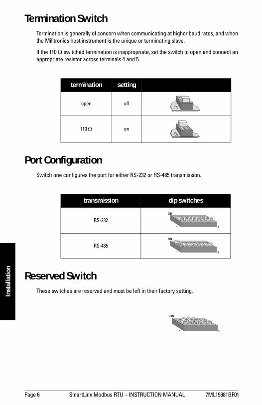
Termination SwitchTermination is generally of concern when communicating at higher baud rates, and when the Milltronics host instrument is the unique or terminating slave.
If the 110 Ω switched termination is inappropriate, set the switch to open and connect an appropriate resistor across terminals 4 and 5.
Port ConfigurationSwitch one configures the port for either RS-232 or RS-485 transmission.
Reserved SwitchThese switches are reserved and must be left in their factory setting.
termination setting
open off
110 Ω on
transmission dip switches
RS-232
RS-485
ON
1 8
ON
1 8
ON
1 6

7ML19981BF01 SmartLinx Modbus RTU INSTRUCTION MANUAL Page 7
mm
mm
m
Installation
Cable Connection
RS-232 Connection PC Connection
RS-232 Connect to Modem
Note: No hardware flow control is used.
SmartLinx Modbus RTU
customer instrument
9-pin D-shell 25-pin D-shell
SmartLinx Modbus RTU
modem
9-pin D-shell 25-pin D-shell
Note: When using a modem, set the value of P758 to 15. See page 18.
2 53
654321
RX
TX GN
D
SHLD
A B
RS
232
RS
485
2 73
654321
RX
TX GN
D
SH
LD
A B
RS
232
RS
485
2 53
654321
RX
TX GN
D
SH
LD
A B
RS
232
RS
485
2 73
654321
RX
TX GN
D
SH
LD
A B
RS
232
RS
485
Page 8 SmartLinx Modbus RTU INSTRUCTION MANUAL 7ML19981BF01
mm
mm
m
Inst
alla
tion
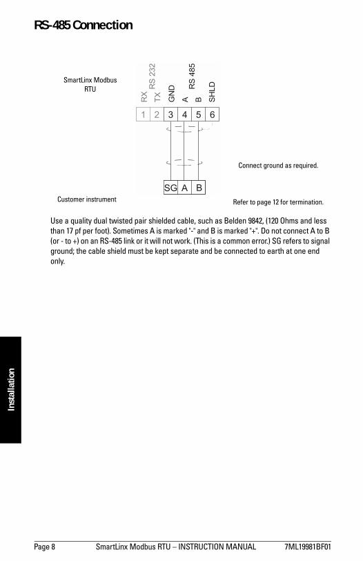
RS-485 Connection
Use a quality dual twisted pair shielded cable, such as Belden 9842, (120 Ohms and less than 17 pf per foot). Sometimes A is marked "-" and B is marked "+". Do not connect A to B (or - to +) on an RS-485 link or it will not work. (This is a common error.) SG refers to signal ground; the cable shield must be kept separate and be connected to earth at one end only.
SmartLinx Modbus RTU
Customer instrument
Connect ground as required.
Refer to page 12 for termination.
6543
B
2
ASG
1
RX
TX GN
D
SH
LD
A B
RS
232
RS
485

7ML19981BF01 SmartLinx Modbus RTU INSTRUCTION MANUAL Page 9
mm
mm
m
Operation
Operation
Communication on the Modbus RTU network is indicated by four SmartLinx LEDs. Three of the LEDs are grouped together at the bottom centre of the module and the other is located on the upper right of the module.
Status LEDs
Initialization LED
Green LED
blinks as the module is initialized remains ON to indicate module is ready
Green LED
blinks as the module is initialized turns ON when the first Modbus RTU
command is received flickers as additional Modbus RTU
commands are received
Red LED
blinks as the module is initialized indicates module failure (replace
module): flashes 4 times per second to
indicate a DPRAM fault flashes 2 times per second to
indicate a ROM fault flashes once per second to indicate
a RAM fault
LED
blinks orange as the module is initialized flashes green during normal operation

Page 10 SmartLinx Modbus RTU INSTRUCTION MANUAL 7ML19981BF01
mm
mm
m
Com
mun
icat
ions
Set
up
Communications Setup
GeneralThe following parameters must be defined in the Milltronics instrument to establish successful communication. Instructions on how to set these parameters are found in the associated instrument manual.
Specific ParametersP751 Baud Rate
Sets the baud rate according to the table:
P752 Parity Mode
Sets the parity mode according to the table:
P753 Slave Address
Sets the slave address. Valid address range is 1 to 247 (factory setting is 1).
Notes: f denotes factory setting. The SmartLinx module only supports 8 data bits, and no hardware flow control. For odd or even parity, use 1 stop bit. For no parity, use two stop bits (as per
Modbus RTU specification).
0 = 1200 bps
1 = 2400 bps
2 = 4800 bps
3 = 9600 bps
4 = 19200 bps f
5 = 38400 bps
0 = no parity f
1 = odd parity
2 = even parity
7ML19981BF01 SmartLinx Modbus RTU INSTRUCTION MANUAL Page 11
mm
mm
m
Comm
unications Setup
P758 Interframe Spacing
The silent time expected, in milliseconds, between two adjacent data packets.
A value of zero 0 selects the traditional 3 and half characters (recommended) as the time interval that separates one command from the next.
Any value from 1 to 32 specifies the time in milliseconds. A value of 33 specifies the highest possible value of 32.678 ms.
Values:0 to 33Preset: 0
Note: When a modem is being used, set this parameter to a value of 15. See page 13 for more information on configuring a modem.

Page 12 SmartLinx Modbus RTU INSTRUCTION MANUAL 7ML19981BF01
mm
mm
m
App
licat
ion
Laye
r
Application Layer
Modbus RTU is an industry standard protocol owned by Schneider Electric and is used throughout process control industries for communication between instruments. Modbus RTU is a master-slave type protocol. An instrument with a SmartLinx Modbus RTU is a slave unit.
SmartLinx Modbus RTU only supports the RTU mode of Modbus, and not ASCII.
A brief description of Modbus RTU is given in this manual. For a full description of the Modbus RTU protocol, contact Schneider Electric or visit their website at www.modicon.com
Parameter Indexes Most parameters used on Milltronics SmartLinx instruments are indexed. Indexing allows a parameter to relate to more than one input or output. For example, some parameters are indexed by measurement point while others are indexed by relay or discrete input.
An index that relates to an input or output is called a Primary Index.
Example of a primary index:
P111[3] = 50 (Relay Control Function for relay 3 = 50, pump control)
Sometimes a parameter requires a second index to allow for multiple values on an indexed input or output. For example a measurement point which calculates a reading on volume can require characterization breakpoints.
These breakpoints are given on a secondary index (the primary index relates to the transducer input).
An index that relates to a previously indexed parameter is called a secondary index.
P111
[1] [2] [3] [4] [5]
7ML19981BF01 SmartLinx Modbus RTU INSTRUCTION MANUAL Page 13
mm
mm
m
Application Layer
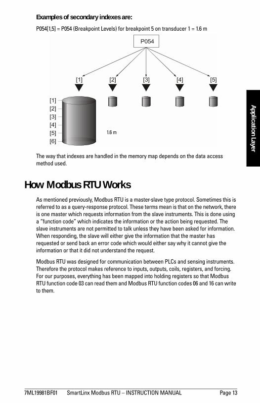
Examples of secondary indexes are:
P054[1,5] = P054 (Breakpoint Levels) for breakpoint 5 on transducer 1 = 1.6 m
The way that indexes are handled in the memory map depends on the data access method used.
How Modbus RTU WorksAs mentioned previously, Modbus RTU is a master-slave type protocol. Sometimes this is referred to as a query-response protocol. These terms mean is that on the network, there is one master which requests information from the slave instruments. This is done using a function code which indicates the information or the action being requested. The slave instruments are not permitted to talk unless they have been asked for information. When responding, the slave will either give the information that the master has requested or send back an error code which would either say why it cannot give the information or that it did not understand the request.
Modbus RTU was designed for communication between PLCs and sensing instruments. Therefore the protocol makes reference to inputs, outputs, coils, registers, and forcing. For our purposes, everything has been mapped into holding registers so that Modbus RTU function code 03 can read them and Modbus RTU function codes 06 and 16 can write to them.
P054
[1] [2] [3] [4] [5]
[1][2][3][4][5][6]
1.6 m

Page 14 SmartLinx Modbus RTU INSTRUCTION MANUAL 7ML19981BF01
mm
mm
m
App
licat
ion
Laye
rTo give you a better idea of how a Modbus RTU message works, a master on network would send a message in a format similar to this:
Where:Slave Address the network address (P753) of the slave you are talking to.
Function Code number that represents a Modbus RTU command. As described above, SmartLinx supports function codes 03, 06, and 16.
Information register data, depending on the function code.
Error Check cyclical redundancy check (CRC).
There is more to the frame than is described above; this is shown to give the user a general idea of what is going on. For a full description, please refer to the Modbus RTU specifications.
Register MappingSmartLinx Modbus RTU only works with the compatible Milltronics SmartLinx instruments (see page 5). These instruments range from one to 10 points of measurement. As such, this manual covers the maximum 10 point measurement capability. If your instrument has fewer than 10 points, ignore data in registers associated to non-existing points of measurement. These registers are present but they contain undefined values.
SlaveAddress
FunctionCode
InformationError
Check
Note: Parameter P999 (Master Reset) is not accessible via the SmartLinx interface.

7ML19981BF01 SmartLinx Modbus RTU INSTRUCTION MANUAL Page 15
mm
mm
m
Application Layer
Data Access MethodsModbus master units may be PLCs, PCs or DCS controllers. By issuing appropriate commands, a controller can access data in three different ways.
Direct AccessCommon values are mapped directly into registers.
Multiple Parameter Access (MPA)This is a hand-shaking method where the Modbus RTU master requests the parameter number, secondary index, decimal place, and format, and then the SmartLinx module writes all 10 primary indexes of that parameter into the mapped registers. The PLC can then read these values. (Recall that in Milltronics products, the memory is arranged as parameter number, primary index, secondary index).
Using Multiple Parameter Access (MPA)Words 40032 through 40035 are used for MPA, allowing continuous monitoring in words 40022 through 40031 of selected parameters for points 1 to 10. Using these words does not allow the changing of parameter values.
1. Write the values into words 40032 through 40035 that define the requested information.
2. Monitor the address variables. When the values returned match those that were written, go to step 3.
3. Read the requested values in words 40022 through 40031. These values are continuously updated. Continue reading from these words until new values are required. At that time, go back to step 1.
Single Parameter Access (SPA). This is a hand-shaking method where the PLC requests the parameter number, primary index, secondary index, decimal place, format, read/write flag, and value, and then the SmartLinx module either reads or writes the value. With this method any value in the Milltronics product can be read or written.
Using Single Parameter Access (SPA)Words 40036 through 40043 are used for SPA, allowing continuous monitoring or demand programming of a parameter for a given indexed measurement point, individually selected for each point.
Note: The design of the SmartLinx module requires that a maximum delay of 0.1 seconds between the time that the master writes a value to the time that it can read the response. Ensure that the master device takes this delay into account.
Note: MPA values are only updated in Run mode.

Page 16 SmartLinx Modbus RTU INSTRUCTION MANUAL 7ML19981BF01
mm
mm
m
App
licat
ion
Laye
rReading a Parameter
1. After setting word 40043 to 0 (read) write the required parameter information to words 40038 through 40042.
2. Monitor the address variables that are reflected back. When the values returned match those that were written, go to step 3.
3. Read the requested value from word 40036. This value is continuously updated. Continue reading from this word until a new value is required. At that time, go back to step 1.
Writing a Parameter
1. Write the required parameter information to words 40038 through 40042, the new value in word 40037 and set word 40043 to 1 (write).
2. Monitor the address variables. When the values returned match those that were written, your write is proceeding.
3. Read the value in word 40036 to confirm that the correct value has been written.4. Set word 40043 back to 0 (read).
Note: Parameters should only be written in Program mode. Ensure word 40044 = 1.
7ML19981BF01 SmartLinx Modbus RTU INSTRUCTION MANUAL Page 17
mm
mm
m
Application Layer
Register Map – Level Products
R40001: Point Status (read only)
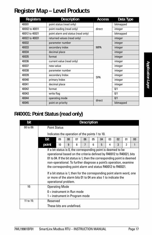
Registers Description Access Data Type40001 point status (read only)
direct
bitmapped
40002 to 40011 point reading (read only) integer
40012 to 40021 point alarm and status (read only) bitmapped
40022 to 40031 returned values (read only)
MPA
integer
40032 parameter number integer
40033 secondary index integer
40034 decimal place integer
40035 format integer
40036 current value (read only)
SPA
integer
40037 new value integer
40038 parameter number integer
40039 secondary Index integer
40040 primary Index integer
40041 decimal place integer
40042 format 0/1
40043 write flag 0/1
40044 operating modedirect
0/1
40045 point on priority bitmapped
bit Description00 to 09: Point Status
Indicates the operation of the points 1 to 10.
bit 09 08 07 06 05 04 03 02 01 00
point 10 9 8 7 6 5 4 3 2 1
If a bit status is 0, the corresponding point is deemed to be operational based on the criteria defined by R40012 to R40021, bits 01 to 04. If the bit status is 1, then the corresponding point is deemed non-operational. To further diagnose a points operation, examine the corresponding point alarm and status R40012 to R40021.
If a bit status is 1, then for the corresponding point alarm word, one or more of the alarm bits 01 to 04 are also 1 to indicate the operational problem.
10: Operating Mode0 = instrument in Run mode1 = instrument in Program mode
11 to 15: ReservedThese bits are undefined.

Page 18 SmartLinx Modbus RTU INSTRUCTION MANUAL 7ML19981BF01
mm
mm
m
App
licat
ion
Laye
r
R40002 to R40011: Point Reading (read only)These words contain the value of parameter P920 (Reading) for points 1 to 10, respectively. The reading is expressed as a percent of full scale, multiplied by 100, giving a range of -20,000 to 20,000 which corresponds to 200.00% to 200.00%. Refer to the Milltronics instrument documentation for a definition of P920.
Note that these values may contain numeric level data for inoperative or malfunctioning points; refer to R40001 point status, and R40012 to R40021 point alarm and status for the actual operational status of the measurement points.
R40012 to R40021: Point Alarm and Status (read only)These words contain the corresponding alarm and status bits for point 1 to 10. So R40012 = measurement point 1 and R40021 = measurement point 10.
Bit status:0 = false1 = true
*Available in version 5.19 or above
R40022-R40031: Returned Values, MPA (read only)These words contain values requested by writing to R40032 to R40035. The type of data and format are specified with that request (see below). In this, the index number 1 to 10, corresponds to R40022 to R40031. So R40022 = measurement point 1 and R40031 = measurement point 10.
R40032: Parameter Number, MPA Specifies the parameter number for the returned value in R40022 to R40031.
bit description00 point not in operation
01 point failsafe timer expired
02 point failed (cable shorted, open, or transceiver problem)
03 point temperature sensor failed
04* Low-Low Alarm (1=ON)
05* Low Alarm (1=ON)
06* High Alarm (1=ON)
07* High-High Alarm (1=ON)
08-12 reserved for future use
13 level emptying
14 level filling
15 scan mode priority

7ML19981BF01 SmartLinx Modbus RTU INSTRUCTION MANUAL Page 19
mm
mm
m
Application Layer
R40033: Parameter Secondary Index, MPASpecifies the parameter index for the value returned in R40022 to R40031. This word is ignored for parameters which dont use indexes.
Some specific Milltronics instrument parameters use indices to address the multiple values stored within the single parameter. See Parameter Indexes on page 12 for details.
R40034: Decimal Place, MPASpecifies the number of decimal places that the returned values are shifted. This affects words R40022 to R40031.
Positive values indicate that the decimal place shifts to the left.
i.e. A 1 means that all returned values have the decimal place shifted 1 space to the left and a returned value of 5,213 is interpreted as 521.3.
Negative values indicate that the decimal place shifts to the right.
i.e. for example if this word is -1, a returned value of 5,213 is interpreted as 52,130.
R40035: Format, MPAThis word sets the format for the returned values.
Values:0 = normal1 = percent of span
R40036: Current Value, SPA (read only)This word is the current value of the parameter specified in the SPA area R40038 to R40042.
R40037: New Value, SPAThis is the new value for the parameter specified in R40038 to R40042. To verify the write check that R40036 returns the value that was written here.
Word R40043 must be set to 1 to enable the write.
R40038: Parameter Number, SPASpecifies the parameter number.
Note: The primary index is implicit in the word location where register 40022 = index 1 and register 40031 = index 10.

Page 20 SmartLinx Modbus RTU INSTRUCTION MANUAL 7ML19981BF01
mm
mm
m
App
licat
ion
Laye
r
R40039: Parameter Secondary Index, SPASpecifies the secondary index for the parameter specified by R40038. This word is ignored for parameters which do not use multiple indexes. See Parameter Indexes on page 12 for details.
R40040: Parameter Primary Index, SPASpecifies the primary index number for the parameter specified by R40038. See Parameter Indexes on page 19 for details.
R40041: Decimal Place, SPASpecifies the number of decimal places that the returned values are shifted. This affects words R40037 and R40036.
Positive values indicate that the decimal place shifts to the left.
i.e. A 1 means that all returned values have the decimal place shifted 1 space to the left and a returned value of 5,213 is interpreted as 521.3.
Negative values indicate that the decimal place shifts to the right.
i.e. for example if this word is -1, a returned value of 5,213 is interpreted as 52,130.
R40042: Format, SPAThis word sets the format for the value in R40036, R40037.
Values:0 = normal1 = percent of span
R40043: Read / Write Flag, SPAThis word determines whether the master system is reading a value from R40036 or writing a value to R40037. It is good practice to confirm the write by reading current value R40036 and then reset this register to zero.
Values:0 = read parameter value in R400361 = continually write new value to R40037 until reset to 0

7ML19981BF01 SmartLinx Modbus RTU INSTRUCTION MANUAL Page 21
mm
mm
m
Application Layer
R40044: Operating ModeThis word sets the operating mode of the Milltronics SmartLinx instrument. The instrument changes mode only when the status of the bit changes.
The operating mode is also set via the instrument keypad.
Bit status0 = run mode1 = program mode
R40045: Point-on-PriorityBits 00 to 09 set the priority status of corresponding points 1 to 10.
Bit status0 = normal1 = priority
e.g.
shows that measurement points 3 and 1 are on priority scan
All other bits are reserved and should contain 0.
If this word is used to control point-on-priority, then the Milltronics instrument must be configured to permit this. Parameter P720 must be set to 1 (manual, SmartLinx) for each point to permit priority control for that point. To enable priority control for all points, store 1 to parameter P720, point 0.
Data TypesThe Milltronics instrument parameters take on many values in various formats, as discussed in the Milltronics SmartLinx instrument manual. For the convenience of the programmer, those values are converted to and from 16-bit integer numbers, since those are easily handled by most PLCs.
IntegerInteger parameter values are by far the most common. For example, parameter P920 (Reading), returns a number representing the current reading (either level or volume, depending on the Milltronics SmartLinx instrument configuration).
bit 09 08 07 06 05 04 03 02 01 00
point 10 9 8 7 6 5 4 3 2 1
bit 09 08 07 06 05 04 03 02 01 00
status 0 0 0 0 0 0 0 1 0 1
Page 22 SmartLinx Modbus RTU INSTRUCTION MANUAL 7ML19981BF01
mm
mm
m
App
licat
ion
Laye
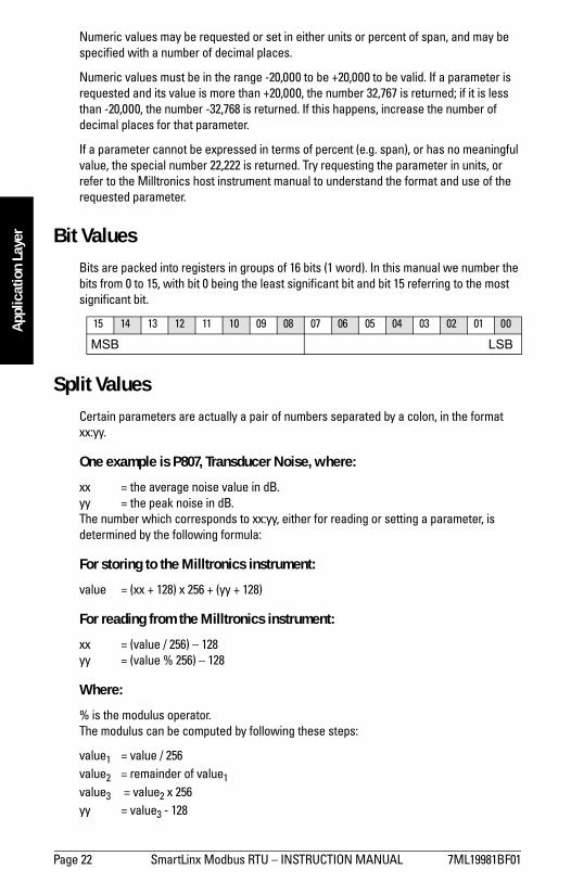
rNumeric values may be requested or set in either units or percent of span, and may be specified with a number of decimal places.
Numeric values must be in the range -20,000 to be +20,000 to be valid. If a parameter is requested and its value is more than +20,000, the number 32,767 is returned; if it is less than -20,000, the number -32,768 is returned. If this happens, increase the number of decimal places for that parameter.
If a parameter cannot be expressed in terms of percent (e.g. span), or has no meaningful value, the special number 22,222 is returned. Try requesting the parameter in units, or refer to the Milltronics host instrument manual to understand the format and use of the requested parameter.
Bit ValuesBits are packed into registers in groups of 16 bits (1 word). In this manual we number the bits from 0 to 15, with bit 0 being the least significant bit and bit 15 referring to the most significant bit.
Split ValuesCertain parameters are actually a pair of numbers separated by a colon, in the format xx:yy.
One example is P807, Transducer Noise, where:
xx = the average noise value in dB.yy = the peak noise in dB.The number which corresponds to xx:yy, either for reading or setting a parameter, is determined by the following formula:
For storing to the Milltronics instrument:
value = (xx + 128) x 256 + (yy + 128)
For reading from the Milltronics instrument:
xx = (value / 256) 128yy = (value % 256) 128
Where:
% is the modulus operator.The modulus can be computed by following these steps:
value1 = value / 256value2 = remainder of value1value3 = value2 x 256yy = value3 - 128
15 14 13 12 11 10 09 08 07 06 05 04 03 02 01 00
MSB LSB

7ML19981BF01 SmartLinx Modbus RTU INSTRUCTION MANUAL Page 23
mm
mm
m
Application Layer
It may simplify programming to notice:
xx = (most significant byte of value) 128yy = (least significant byte of value) 128
Text Messages
If a Milltronics instrument parameter returns a text message, that message is converted to an integer and provided in the register. The numbers are shown in the table below:
Note: Used for Level products only.
Number Text Message as displayed on LCD22222 invalid value
30000 off
30001 on
30002 ≡ ≡ ≡ ≡
30003 (parameter does not exist)
30004 err
30005 err1
30006 open
30007 shrt
30008 pass
30009 fail
30010 hold
30011 lo
30012 hi
30013 de
30014 en
30015 (parameter has not been set)
-32768 value is less than -20,000
32767 value is greater than 20,000
Page 24 SmartLinx Modbus RTU INSTRUCTION MANUAL 7ML19981BF01
mm
mm
m
App
licat
ion
Laye
r
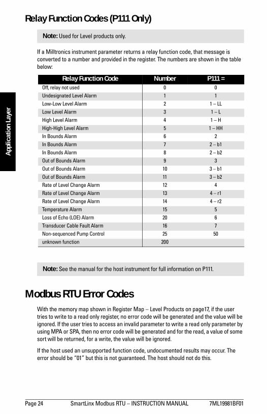
Relay Function Codes (P111 Only)
If a Milltronics instrument parameter returns a relay function code, that message is converted to a number and provided in the register. The numbers are shown in the table below:
Modbus RTU Error CodesWith the memory map shown in Register Map Level Products on page17, if the user tries to write to a read only register, no error code will be generated and the value will be ignored. If the user tries to access an invalid parameter to write a read only parameter by using MPA or SPA, then no error code will be generated and for the read, a value of some sort will be returned, for a write, the value will be ignored.
If the host used an unsupported function code, undocumented results may occur. The error should be 01 but this is not guaranteed. The host should not do this.
Note: Used for Level products only.
Relay Function Code Number P111 =Off, relay not used 0 0
Undesignated Level Alarm 1 1
Low-Low Level Alarm 2 1 LL
Low Level Alarm 3 1 L
High Level Alarm 4 1 H
High-High Level Alarm 5 1 HH
In Bounds Alarm 6 2
In Bounds Alarm 7 2 b1
In Bounds Alarm 8 2 b2
Out of Bounds Alarm 9 3
Out of Bounds Alarm 10 3 b1
Out of Bounds Alarm 11 3 b2
Rate of Level Change Alarm 12 4
Rate of Level Change Alarm 13 4 r1
Rate of Level Change Alarm 14 4 r2
Temperature Alarm 15 5
Loss of Echo (LOE) Alarm 20 6
Transducer Cable Fault Alarm 16 7
Non-sequenced Pump Control 25 50
unknown function 200
Note: See the manual for the host instrument for full information on P111.

7ML19981BF01 SmartLinx Modbus RTU INSTRUCTION MANUAL Page 25
mm
mm
m
Troubleshooting
Troubleshooting
GenerallyIn all cases, first check that the SmartLinx Modbus RTU Module has passed its on-going built-in self test (instrument parameter P790). The result should be PASS.
If FAIL is indicated, either the module is defective, or the module connector on the Milltronics instrument is defective.
If ERR1 is indicated, the Milltronics software doesnt recognize the ID number of the installed module. Please contact Milltronics or your distributor for instructions and/or upgraded Milltronics SmartLinx compatible instrument software.
SpecificallyQ1: I tried to set a Milltronics instrument parameter using a SPA write, but the
parameter remains unchanged.
A1.1: Some parameters can only be changed when the Milltronics instrument isnt scanning. Try putting the Milltronics instrument in program mode, using operating mode R40044.
A1.2: Try setting the parameter from the keypad. If it cant be set using the keypad, check the lock parameter (P000).
Q2: I have communications, but periodically the Modbus master gets a series of Modbus time out errors, and the red LED on the SmartLinx module comes on.
A2.1: Check the configuration of the SmartLinx module and if you are using no parity (P752), then verify that the Modbus master is set for two stop bits.
A.2.2: Consult your Milltronics representative.
Q3: Ive connected using RS-485 and checked all the communications parameters and wiring, and Im still not getting communication.
A.3.1 Check to make sure that the RS-485 A line at the Milltronics SmartLinx instrument is connected to the A line at the master, and that the B line is connected to the B line.
Page 26 SmartLinx Modbus RTU INSTRUCTION MANUAL 7ML19981BF01
mm
mm
m
Wiri
ng G
uide
lines
Wiring Guidelines
The improper wiring and improper chose of cables is one of the most common sources of communication problems. Listed below are some comments that should help:
Length (maximum):
15 meters (50 feet) for RS-232
1200 meters (4000 feet) for RS-485
make sure that communication cable is run separately from power and control cables (i.e. do not tie wrap your RS-232 cable to the 120 V AC power cable or have them in the same conduit)
cable is shielded, and the cable should be connected to ground at one end of the cable only
24 AWG (minimum)
follow proper grounding guidelines for all instruments on the LAN
use good quality, communication grade (shielded, twisted pairs) cable that is recommended for the RS standard that you are using
7ML19981BF01 SmartLinx Modbus RTU INSTRUCTION MANUAL Page 27
mm
mm
m
Index
IndexAAbout this Manual ............................................3About this Module ............................................1
Typical RS-232 System ..........................2Typical RS-485 System ..........................1
Address ..................................................... 10, 14AiRanger DPL Plus ..................................... 4, 5AiRanger Series ................................................5
AiRanger DPL Plus ........................... 4, 5AiRanger SPL .................................... 4, 5AiRanger XPL Plus ........................... 4, 5CraneRanger ..................................... 4, 5InterRanger DPS 300 ....................... 4, 5
AiRanger SPL .............................................. 4, 5AiRanger XPL Plus ..................................... 4, 5Application Layer .......................................... 12
Data Access ......................................... 15How Modbus RTU Works .................. 13Parameter Indexes .............................. 12Register Mapping ................................ 14
Audience ............................................................3AWG ................................................................. 26BBaud rate ............................................................4Baud rate (P751) ............................................ 10Bit Values ........................................................ 22CCable ............................................................ 4, 26
Length ..................................................... 26Type ........................................................ 26
Cable Connection See Connection ..............7Cable See Wiring Guidelines ........................4Communication parameters ....................... 10Communication Settings ................................4
Baud rate ..................................................4Hardware flow control ..........................4Parity .........................................................4Stop bit ......................................................4
Communications Setup ................................ 10Specific Parameters ........................... 10
Compatible Instruments ........................... 4, 5Connection ................................................... 4, 7
RS-232 .......................................................7RS-485 .......................................................8
CraneRanger ............................................... 4, 5Current Value ................................................. 19
DData Access ....................................................15
Direct Access ........................................15Multiple Parameter Access ...............15Single Parameter Access ..................15
Data bits .............................................................4Data Types .......................................................21
Bit Values ...............................................22Integer .....................................................21P111 Values ...........................................24Split Values .............................22, 23, 24Text Messages .....................................23
Decimal Place ......................................... 19, 20Delay .................................................................15Direct Access ..................................................15EError Check ......................................................14Error Codes ......................................................24FFactory setting .......................................... 6, 10Format ....................................................... 19, 20Function Code .................................................14HHardware flow control ....................................4IIndexes .............................................................12
Primary ...................................................12Secondary ..............................................12
Information ......................................................14Installation .........................................................5Integer ..............................................................21Interconnection See Connection .................7Interframe spacing ........................................11InterRanger DPS 300 ................................. 4, 5LLEDs .....................................................................9
Initialization ..............................................9Status ........................................................9
Level Products ........................................ 23, 24Register Map .........................................17
MMapping ...........................................................14Master Reset (P999) ......................................14Modbus RTU ........................................ 1, 3, 12modem ........................................................ 7, 11Module Outline .................................................5MPA See Multiple Parameter Access .....15

Page 28 SmartLinx Modbus RTU INSTRUCTION MANUAL 7ML19981BF01
mm
mm
m
Inde
xMultiple Parameter Access (MPA) ........... 15NNew Value ...................................................... 19OOperating Mode ...................................... 17, 21Operation ............................................................9Outline .................................................................5PP720 .................................................................. 21P751 .................................................................. 10P752 .................................................................. 10P753 .................................................................. 10P758 Interframe spacing .............................. 11P999 .................................................................. 14Parameter Indexes ....................................... 12Parameter Number ................................ 18, 19Parameter Secondary Index ...................... 19Parameters ..................................................... 10
Interframe spacing .............................. 11Reading in block .................................. 16Writing in a block ................................. 16
Parity ...................................................................4Parity (P752) .................................................... 10Point Alarm ..................................................... 18Point Reading ................................................. 18Point status ..................................................... 17Point-on-Priority ............................................ 21Port Configuration ............................................6
RS-232 .......................................................6RS-485 .......................................................6
Primary Index .......................................... 12, 20RRead / Write Flag ........................................... 20Register Map ........................................... 17, 24
Current Value (R40036) ....................... 19Decimal Place, MPA (R40034) .......... 19Decimal Place, SPA (R40041) ........... 20Format, SPA (R40042) ......................... 20Format,MPA (R40035) ......................... 19New Value (R40037) ............................ 19Operating Mode (R40044) .................. 21Parameter Number, MPA (R40032) . 18Parameter Number, SPA (R40038) .. 19Parameter Primary Index (R40040) .. 20Parameter Secondary Index (R40039) .
20Point Alarm (R40012 to R40021) ........ 18Point Reading (R40002 to R40011) .... 18Point-on-Priority (R40045) .................. 21Read / Write Flag, SPA (R40043) ...... 20
Returned Values (R40022 to R40031) 18Secondary Index (R40033) ..................19
Register Mapping ..........................................14Registers ..........................................................14Relay .................................................................24Relay Function Codes ...................................24Reserved Switch ..............................................6Returned Values .............................................18RS-232 ........................................................... 6, 7
Modem connection ................................7PC Connection ........................................7
RS-485 .................................................................6Connection ...............................................8
SSecondary Index ............................................20Secondary Indexes ........................................13Shielded cable ................................................26Single Parameter Access (SPA) ................15SITRANS LU 01 ........................................... 4, 5SITRANS LU 02 ........................................... 4, 5SITRANS LU 10 ........................................... 4, 5Slave Address .................................................14Slave Address (P753) ....................................10SPASee Single Parameter Access ............15Specifications ...................................................4
Cable .........................................................4Communication Settings ......................4Compatible Instruments .......................4Connection ...............................................4Termination ..............................................4
Split Values .......................................22, 23, 24Status ................................................................18Stop bit ................................................................4TTermination ................................................. 4, 6Text Messages ...............................................23Troubleshooting .............................................25WWiring .................................................................7Wiring Guidelines .................................... 4, 26

*7ml19981BF01*Rev. 1.2
www.siemens-milltronics.com
Siemens Milltronics Process Instruments Inc.
1954Technology Drive, P.O. Box 4225
Peterborough, ON, Canada K9J 7B1
Tel: (705) 745-2431 Fax: (705) 741-0466
Email: [email protected]
Siemens Milltronics Process Instruments Inc. 2004
Subject to change without prior notice
Printed in Canada


![옵션매뉴얼 2017.12.01 MODBUS RTU 위한 RTU - DABIT Protocol Memory...옵션매뉴얼 2017.12.01 6 [7] 페이지번호(옵션): 초기값 “0”을 유지합니다. 메시지를](https://static.fdocuments.net/doc/165x107/5fa6e400bda011618d34b8f9/ee-20171201-modbus-rtu-oeoe-rtu-dabit-protocol-memory-ee.jpg)