SmartFade Service Manual - Madman Production · Memory Card Test ... This test can also be used as...
20
Copyright © Electronic Theatre Controls, Inc. All Rights reserved. Product information and specifications subject to change. Part Number: 7219M3200 Rev A Released: February 2005 Control Console Service Manual Revision A
Transcript of SmartFade Service Manual - Madman Production · Memory Card Test ... This test can also be used as...
Copy r i gh t © E lec t r on i c Thea t re Con t ro l s , I nc .A l l R i gh t s r ese rved .
P roduc t i n f o rma t i on and spec i f i ca t i ons s ub jec t t o change .Pa r t Number : 7219M3200 Rev A
Re leased : Feb rua ry 2005
Control ConsoleService ManualRevision A

ET C ® and Smar tFade™ a re e i t he r r eg i s t e red t r ademarks o r t r ademarks o f E l ec t r on i c Thea t re Con t ro l s , I nc . i n t he Un i ted S ta tes and o the r coun t r i es .
A l l o t he r t r ademarks , bo th ma rked and no t ma rked , a re the p rope r t y o f t he i r r espec t i ve owne rs .

i
T a b l e o f C o n t e n t sIntroduction . . . . . . . . . . . . . . . . . . . . . . . . . 1
Help from ETC Technical Services . . . . . . . . . . . . . . . . . . . . . . . . . . 1
Section 1: SmartFade Block Diagram . . . . . . . . . . . . . .2Section 2: Built-In Test Routines . . . . . . . . . . . . . . . . . .2
General User Interface Test . . . . . . . . . . . . . . . . . . . . . . . . . . . . . . . 3LED Test . . . . . . . . . . . . . . . . . . . . . . . . . . . . . . . . . . . . . . . . . . . . . . 3LCD Test . . . . . . . . . . . . . . . . . . . . . . . . . . . . . . . . . . . . . . . . . . . . . . 3DMX Test . . . . . . . . . . . . . . . . . . . . . . . . . . . . . . . . . . . . . . . . . . . . . 3MIDI Test . . . . . . . . . . . . . . . . . . . . . . . . . . . . . . . . . . . . . . . . . . . . . . 4USB Test . . . . . . . . . . . . . . . . . . . . . . . . . . . . . . . . . . . . . . . . . . . . . . 4Memory Card Test. . . . . . . . . . . . . . . . . . . . . . . . . . . . . . . . . . . . . . . 4System ID Test . . . . . . . . . . . . . . . . . . . . . . . . . . . . . . . . . . . . . . . . . 5Internal Memory Test . . . . . . . . . . . . . . . . . . . . . . . . . . . . . . . . . . . . 5Firmware Upgrade. . . . . . . . . . . . . . . . . . . . . . . . . . . . . . . . . . . . . . . 5System Shutdown . . . . . . . . . . . . . . . . . . . . . . . . . . . . . . . . . . . . . . . 5
Section 3: General Repair Strategy . . . . . . . . . . . . . . . .6Section 4: Hardware Level Troubleshooting . . . . . . . . .6
DMX - In/Out . . . . . . . . . . . . . . . . . . . . . . . . . . . . . . . . . . . . . . . . . . . 6Immediate Help. . . . . . . . . . . . . . . . . . . . . . . . . . . . . . . . . . . . . . 6
MIDI - In/Out . . . . . . . . . . . . . . . . . . . . . . . . . . . . . . . . . . . . . . . . . . . 6Immediate Help. . . . . . . . . . . . . . . . . . . . . . . . . . . . . . . . . . . . . . 6
Section 5: Recommended Spare Parts . . . . . . . . . . . . .7
Appendix A: SmartFade PCB’s . . . . . . . . . . . . . . . . . . . . 9SmartFade Main PCB . . . . . . . . . . . . . . . . . . . . . . . . . . . . . . . . . . . 10SmartFade I/O PCB . . . . . . . . . . . . . . . . . . . . . . . . . . . . . . . . . . . . 12SmartFade Extension PCB . . . . . . . . . . . . . . . . . . . . . . . . . . . . . . . 13SmartFade LCD Raiser PCB. . . . . . . . . . . . . . . . . . . . . . . . . . . . . . 14SmartFade Memory Card PCB . . . . . . . . . . . . . . . . . . . . . . . . . . . . 14

ii SmartFade Service Manual
1
I n t r oduc t i on
This document is intended to assist service centers and repair facilities in testing, troubleshooting and repairing ETC SmartFade Consoles. Included is a series of internal diagnostic tests, theories of operation, and repair strategies.
He lp f rom ETC Techn ica l Serv icesIf you are having difficulties, your most convenient resources are provided in the user manual provided with your product or this service manual. To search more widely, try the ETC website at www.etcconnect.com. If none of these resources is sufficient, contact ETC Technical Services directly at one of the offices identified below. Emergency service is available from all ETC offices outside of normal business hours.
Amer icasETC Corporate HeadquartersTechnical Services Department3031 Pleasant View RoadMiddleton, WI 53562800 775-4382 (USA toll-free)+1-608 [email protected]
EuropeETC Europe, Ltd.Technical Services Department5 Victoria Industrial EstateVictoria Road, London W3 6UU England+44 (0)20 8896 [email protected]
Asi aETC Asia, Ltd.Technical Services DepartmentRoom 605-606Tower III, Enterprise Square9 Shueng Yuet RoadKowloon Bay, Kowloon, Hong Kong+852 2799 [email protected]

2 SmartFade Service Manual
Sect ion 1 : Smar tFade B lock D iagram
Prints for all five circuit boards used in the SmartFade console are located on page 9 of this manual.
Sect ion 2 : Bu i l t - In Tes t Rou t ines
The SmartFade console provides a built-in self test facility that tests all sub-systems, accomplishes a memory deep clear, initiates a software upgrade, and assist the technician to identify and locate potential problems.
• To enter the self-test menu - hold down the button during power up. At the end of the initial LED fade, the system should automatically enter the diagnostics mode.
In diagnostics, there are a number of tests for all the sub-systems. By pressing the button, the next test is entered.
Mains110V/60Hz
or 230V / 50Hz
Power Supply(external)
12V1.5A
SmartFade I/O PCB7219B5002DMX/MIDI/USB/Power Connectors
5V Power Supply
I/O Driver circuitry
SmartFade Main PCB7219B5001Faders, Buttons, LED's,
Processor, Memory, 3.3V PSU,
Memory backup power
SmartFade LCD Raiser PCB7219B5004LCD Backlight
LCD Display
LCD Backlight
ESD Shield (4x Screws)
SmartFade Extension PCB7219B5003Faders, Buttons, LED's
FadersButtonsLED's
(50Pin Flat Ribbon)
SmartFade Memory Card PCB7219B5005 SD-Card Socket
SPI
(8x Solder joints)
[ ]
[ ]

Built-In Test Routines 3
Genera l User In te r face Tes tThe first test is a general user interface test. This test provides feedback on all the user interface elements including buttons, faders, and encoders. In addition this test provides visual feedback to the user via the LCD and Button LED’s.
The following functions are implemented within this test:
Press the button to proceed to the next test.
LED Tes tThis test Turns on all LED’s of the board starting with all red bump buttons, then all green bump buttons, and lastly control buttons. To proceed to the next color / test, press the button.
LCD Tes tThis test will cycle through the characters of the LCD display. The same character will display on all LCD positions for a half second, then will proceed to the next character. Press the button to proceed to the next test.
DMX Tes tThis is a simple loop back test. Connect the SmartFade DMX input to the output. This test will initially send DMX out and attempt to receive it through its own input. If the transmitted pattern and the received pattern match up, the RDM direction switch over capability is also checked. Under normal working conditions this test will complete automatically in less than
Channel faders: Set the intensity of the corresponding bump-button LED.
Bump buttons: Blinks the corresponding button, and turns it off after release.
A-fader: Contrast of the LCD Display(A-fader should be at 100% for this test!)
B-fader: LCD backlight and Power button intensity.
Bump Master fader: ETC Logo intensity
Grand Master fader: Control buttons intensity
Independent 1 button: Switch the Bump buttons to RED
Independent 2 button: Switch the Bump buttons to Green
LCD:
The LCD will display the received user interface messages.• It will display the message source (button, fader, or
encoder).• The button, fader, or encoder number.• The message number (wrap-around text after 100
messages)• The Message Value:
• Button = up / down• Encoder = up / down• Fader = Value (0 255)
[ ]
[ ]
[ ]

4 SmartFade Service Manual
a second. If this test fails, consult the DMX In / Out section of this manual for solutions.
To bypass this test press the button.
MI DI Tes tThis is a simple loop back test. Connect the SmartFade MIDI input to the output. The test completes automatically in less than a second. If the test fails, please consult the MIDI In/Out section of this manual for solutions.
To bypass this test, press the button.
USB Tes tThis test will check the communications between the Processor and the USB chip. Under normal working conditions this test will conclude as “passed” in less than a second.
If there are problems, the LCD will show what bit-patterns were written to the USB-chip and what patterns came back. These patterns help to indicate shorted or open circuits on the system’s data bus.
After the completion of this test, the interrupt line is checked. If this is stuck at any level, an error message is generated. If errors are generated, or to proceed to the next test, press the button.
Mem ory Card Tes tThis test will check the memory card interface. If the memory card slot is empty, the display will show the “Write-Protect Switch” as On.
During insertion of a SD/MMC card, this switch will change status to off, and then in the end position to whatever the switch on the card was actually set to.
If the card makes electrical contact, the test routine will send a card-initialize command, and will wait for an answer from the card. When the answer arrives, the electrical interface to this card functions properly and the test will show a “pass”. If this test does not complete as passed after a known good memory card was inserted, check the electrical connections between the main and SD-card PCB’s. Also check the socket for bent pins or other mechanical damage.
To proceed to the next test, press the button.
N o t e : This test can also be used as a simple DMX cable tester / DMX distribution chain tester.
N o t e : This test can also be used as a simple MIDI cable tester / MIDI distribution chain tester.
N o t e : This test will not check USB communications between the Console and a PC. This can be achieved by performing a software upgrade cia USB. The SmartFade console will display as a MIDI audio device in the PC’s device manager.
[ ]
[ ]
[ ]
[ ]

Built-In Test Routines 5
Sys tem ID Tes tThis test will present the readout of the hardware versions of the board. It should read 000 for SmartFade 1248 and 001 for SmartFade 2496. All other numbers are reserved for future development.
End the test procedure by disconnecting and reapplying power to the console. At reboot the console will operate in the current mode.
I n te rna l Memory Tes t
This test writes a certain pattern to all memory locations of the internal memory, and compares the readout to what it should be.
Under normal working conditions the console displays a progress status update (writing 0 100%, reading 0 100%), and then a test “passed” message. If there is a mismatch
between the written and read back data, the console displays a message with the Memory address, written data and read back data. Use this data to detect eventual short or open circuits on the data / address bus. This test completes in less than 10 seconds.
To proceed to the next test, press the button.
F i r mware UpgradeIt is possible to select a firmware upgrade option here. If [YES] is selected, the console changes into firmware update mode and awaits new firmware either via SD-Card or USB interface. Use the procedure described in the user manual to load the new firmware into the system. To abort the firmware upgrade process, cycle power on the console.
Sys tem ShutdownAfter completion of all tests, the console will change to System Shutdown mode and remain in this mode until the power button is pressed.
C A U T I O N : Progressing to the next menu, Internal Memory Test, will erase the entire memory in your board, including all show data and custom settings. To eliminate this possibility disconnect and reconnect the power to the console.
C A U T I O N : This test will erase the entire memory, including all show data and custom settings, and restore the console to factory defaults! Pressing the button will initate the memory test immediately. To eliminate this possibility disconnect the power to the console.
[ ]
[ ]

6 SmartFade Service Manual
Sect ion 3 : Genera l Repa i r S t ra tegy
The possibility of board level repairs without special tools is very limited in this product due to the extensive use of SMD components.
All electronic repairs should be limited to changing driver chips on the I/O boards, and changing faders on the main and extension assemblies. Any deeper problem should be resolved by swapping PCB’s.
Sect ion 4 : Hardware Leve l T roub leshoo t ing
DMX - In /OutThe power supply connected to unit needs to be able to provide at least 1.5A of 12V. The console internal voltage must, under all working conditions (e.g. all LEDs on), always be greater than 10V pre-voltage regulator, otherwise the DMX-In isolated power supply will not function.
DMX-In is the first function that stops working when the supply voltage drops below the minimum operating voltage.
• If DMX-In is not working anymore, there are a number of things to check:
• Check the voltage across the I/O Board. Check C-19 for a voltage greater than 10VDC.
• The DMX-In driver chip might be broken. Replace U5 with a new 75176 chip.
• Check the voltage on the Isolated Power Supply test points. It needs to be 5VDC.
• Check for a 100KHz pulse, 50% duty-cycle on U1, Pin 3. If there are no pulses, the problem might be on the main PCB.
• If DMX-Out does not function, it is likely that the DMX-Out driver chip is broken.
• Replace the 75176 RD-485 driver chip U1, located on the I/O PCB.
Immedia te He lpIf the DMX-Out chip is broken and DMX-In is not used, it is possible to swap the DMX-In (U5) with the DMX-Out (U2) chips to get the DMX-Out functioning again.
MID I - I n /Out• If MIDI-In is not working, it is likely that the MIDI-In chip is broken.
• This is a standard 6N137 opto-coupler chip U4, located on the I/O PCB.
• If MIDI-Out is not working, it is likely that the MIDI-Out chip is broken.
• This is a standard 74ACT02 logic chip U1, located on the I/O PCB.
Immedia te He lpIf the MIDI-IN chip is broken and DMX-In is not used, it is possible to swap the DMX-In opto-isolator (U3) with the MIDI-In (U4) chip, to get MIDI-In going again.

Recommended Spare Parts 7
Sect ion 5 : Recommended Spare Par ts
Description ETC Part # Location
Power Supply USPS291 & PS291-J replaces PS236 after February 2005
Power Supply EU PS240Power Supply UK PS241MIDI-Out driver chip, 74ACT02 Z1232 I/O PCB, U1MIDI-In driver chip, 6N137 Z423 I/O PCB, U4DMX-In/Out driver chip, 75176 Z216 I/O PCB, U2 & U5Slide Pot Knob 4110A4036 All FadersChannel Fader P152 Channel Faders
Master Fader P153 Master and Playback Faders
Encoder L1080 Main PCBEncoder knob top HW8339Encoder knob body HW8343Button Key Cap 7219A4006Channel 1-24 Key Pad Set 7219A2002Channel 25-48 Key Pad Sett 7219A200312/48 Main Key Pad Assy 7219A200124/96 Main Key Pad Assy 7219A200512/48 Face Panel Overlay 7219A400124/96 Face Panel Overlay 7219A4002Main PCB 7219B5001I/O PCB 7219B5002Extension PCB 7219B5003SD-Card PCB 7219B5005LCD PCB 7219B5004

8 SmartFade Service Manual

9
Appendix 1Smar tFade PCB ’s
This appendix contains the following sections:
• SmartFade Main PCB. . . . . . . . . . . . . . . . . . . . . . . . . . . . . . . .10
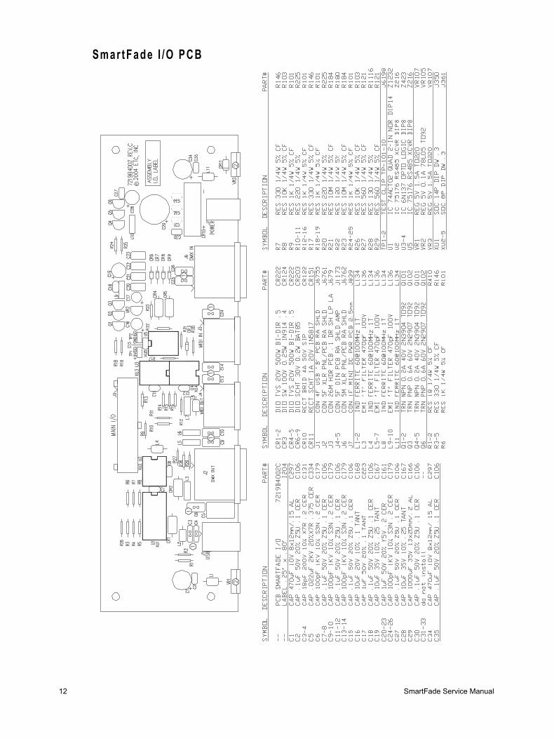
• SmartFade I/O PCB . . . . . . . . . . . . . . . . . . . . . . . . . . . . . . . . .12
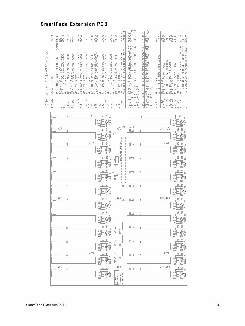
• SmartFade Extension PCB . . . . . . . . . . . . . . . . . . . . . . . . . . .13
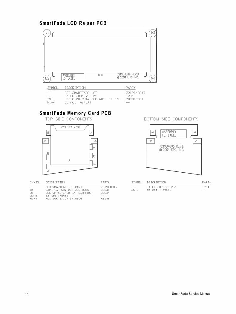
• SmartFade LCD Raiser PCB . . . . . . . . . . . . . . . . . . . . . . . . . .14
• SmartFade Memory Card PCB . . . . . . . . . . . . . . . . . . . . . . . .14

10 SmartFade Service Manual
Smar tFade Ma in PCB
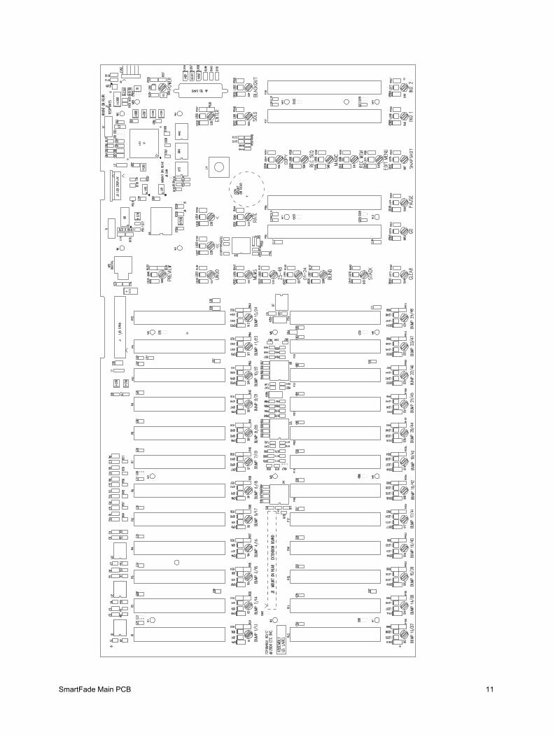
SmartFade Main PCB 11
12 SmartFade Service Manual
Smar tFade I /O PCB
SmartFade Extension PCB 13
Smar tFade Ex tens ion PCB
14 SmartFade Service Manual
Smar tFade LCD Ra ise r PCB
Smar tFade Memory Card PCB

SmartFade Memory Card PCB 15

Corporate Headquarters 3031 Pleasant View Road, P.O. Box 620979, Middleton, Wisconsin 53562-0979 USA Tel +608 831 4116 Fax +608 836 1736London, UK Unit 5, Victoria Industrial Estate, Victoria Road, London W3 6UU, UK Tel +44 (0)20 8896 1000 Fax +44 (0)20 8896 2000Rome, IT Via Ennio Quirino Visconti, 11, 00193 Rome, Italy Tel +39 (06) 32 111 683 Fax +39 (06) 32 656 990Holzkirchen, DE Ohmstrasse 3, 83607 Holzkirchen, Germany Tel +49 (80 24) 47 00-0 Fax +49 (80 24) 47 00-3 00Hong Kong Room 605-606, Tower III Enterprise Square, 9 Sheung Yuet Road, Kowloon Bay, Kowloon, Hong Kong Tel +852 2799 1220 Fax +852 2799 9325Web: www.etcconnect.com Email: (Americas) [email protected] (UK) [email protected] (DE) [email protected] (Asia) [email protected]: (Americas) [email protected] (UK) [email protected] (Asia) [email protected] Comments about this document: [email protected]
7219M3200 Rev A Released 2/2005 Copyright © 2005 ETC. All Rights Reserved. Product information and specifications subject to change.