
SMARTDRIVE PREMIER SYSTEM · SmartDrive Premier System POCLAIN HYDRAULICS 6 15/01/2014...
52
T E C H N I C A L C A T A L O G SMARTDRIVE PREMIER SYSTEM ELECTRONIC TRACTION AND HYDROSTATIC TRANSMISSIONS CONTROL
Transcript of SMARTDRIVE PREMIER SYSTEM · SmartDrive Premier System POCLAIN HYDRAULICS 6 15/01/2014...

T E C H N I C A L C A T A L O G
SMARTDRIVE PREMIER SYSTEMELECTRONIC TRACTION AND HYDROSTATIC TRANSMISSIONS CONTROL
SmartDrive Premier System POCLAIN HYDRAULICS
2 15/01/2014
Methodology :This document is intended for manufacturers of machines that incorporate Poclain Hydraulics products. It describes the technical characteristics of Poclain Hydraulics products and specifies installation conditions that will ensure optimum operation. This document includes important comments concerning safety. They are indicated in the following way:
This document also includes essential operating instructions for the product and general information. These are indicated in the following way:
The views in this document are created using metric standards. The dimensional data is given in mm and in inches (inches are between brackets and italic)
Safety comment.
Essential instructions.
General information .
Information on the model number.Information on the mo-del code.
Weight of component without oil.
Volume of oil.
Units.
Tightening torque.
Screws.
Information intended for Poclain-Hydraulics personnel.

15/01/2014 3
CONTENTPOCLAIN HYDRAULICS SmartDrive Premier System
Acc
esso
ries
Cha
ract
eris
tics
Inst
alla
tion
CHARACTERISTICS 4
Foreword 4Operating principles 5System main characteristics 7SmartDrive™ Off-Road System Diagram of working principles 9SmartDrive™ Master System Description of functions 10
ACCESSORIES 13
SmartDrive™ ECU 13Input / output characteristics 15Communication connector 17SmartDrive™ communication cable 1856-pin main connector 19SmartDrive™ Master cable 21SmartDrive™ Off-Road cable 22Traction control (in-line) valve 23Traction control (flanged) valve 25AMP Connector 27Speed sensor T4 28M12 cable 30Rotary potentiometer 31SmartDrive™ Premier identification 33SmartDrive™ Premier list of components 34
INSTALLATION 37
Installation 37SmartDrive™ Off-Road System setting parameters, downloading,calibration, diagnostics 43First level diagnostic 44Appendix 46

SmartDrive Premier System POCLAIN HYDRAULICS
4 15/01/2014
FOREWORDThe SmartDriveTM Premier consists of the SmartDriveTM Off-Road System and SmartDriveTM Master System functions.
SmartDriveTM Off-Road System forewordHydrostatic transmissions have an inherent differential function. As consequence, the maximum torque which can be transmitted to drive wheels supplied by one pump is limited by the wheel with the poorest adhesion. Loss of adherence can cause loss of control or immobilization of the vehicle, premature tire wear, excess fuel consumption or damage to the ground.The SmartDrive™ Off-Road System from Poclain Hydraulics provides complete control of wheel speed, thus preventing such problems.
SmartDriveTM Master System forewordPoclain Hydraulics has created and developed SmartDriveTM Master System, a system that simplifies and optimizes the running of hydrostatic transmissions of mobile machinery. It comprises a computer that regulates the running of hydrostatic transmission components (engine, hydraulic ground drive pump, hydraulic motors, and brakes) through sensors and actuators.The on-board software calculates the machine's ground drive speed in accordance with the driver setting and the programmed acceleration and deceleration ramps. These ramps, which are among the many parameters that enable the machine's behavior to be customized, determine the vehicle's responsiveness and aggressiveness.The combination of the flexibility of the electronics and the power of the hydraulics makes this a system which can be adapted and set up for all driving styles.
It consists of the following components:
Flow control valve
Wheel speed sensor
Turn sensor
Regulating computer
Hand held terminal
Set-up / Calibration / Diagnostic by computer
Set-up / Calibration / Diagnostic by computer
SA control pump
CHARACTERISTICS

POCLAIN HYDRAULICS SmartDrive Premier System
15/01/2014 5
Acc
esso
ries
Cha
ract
eris
tics
Inst
alla
tion
OPERATING PRINCIPLESSmartDrive™ Off-Road System operating principlesThe speed sensors incorporated in the hydraulic motors continuously measure the rotation speed of each powered wheel. The regulating computer compares those speeds and if necessary reduces hydraulic flow to the wheel which is slipping. (by means of a regulating valve).
SmartDrive™ Off-Road System standard configuration In the standard configuration of the Off-Road System the double regulating valves are located on the hydraulic motor supply lines.
On a flat surfaceExample of a four drive wheel machine running on a flat surface in a straight line, in perfect conditions (perfect adherence, identical tire rolling circumference…):
• Pressures at P, P1 and P2 are equal;• Flow Q = Q1 + Q2;• The rotation speeds of the wheels number 1 and 2 are the same.
If the wheel number 1 loses adherence :The overall circuit pressure falls to the one dictated by wheel number 1, which is slipping;• Flow Q1 becomes greater than Q2;The rotation speed of wheel n°1 increases and the one of wheel number 2 falls to zero speed.If there is no traction control, this will cause the machine to stop.
The SmartDrive™ Off-Road System controls wheel speeds by varying the flow (of wheels supply) within the double regulating valve (1). It reduces flow Q1 and increases the pressures P and P2 to provide machine traction and prevent wheel skid consequences. When all the wheels have reached the same rotation speed, the double regulating valve (1) opens completely. It will only close if a difference in wheel speed occurs again.This control system operates continuously. The regulating mechanism comes into play only in accordance with the parameters which have been set by the machine manufacturer.
When traveling down a slopeThe system works on the flat surface as well as up or down grades. For machines which need to operate on slopes in excess of 20%, the following configuration is recommended by Poclain Poclain HydraulicsHydraulics.
Steep slope circuit:For machines which have to work on steep slopes (e.g. grape-harvesters, post emerge sprayers) the double regulating valve is installed on the return circuit of the front wheel. The system will then limit the return flow from the front motors and control the speed of the machine on the slope.
Turn detectionThe SmartDrive™ Off-Road System operates also during turns. It detects the machine's turning direction (to the right, to the left or straight on) by means of a turn detector and either disable the regulation or corrects the flow to the wheels depending on the steering geometry.
Unlike traditional flow dividers the system engages ifself only when wheel slip occurs. Only one pump is required for a vehicle with two or more drive wheels.
SmartDrive Premier System POCLAIN HYDRAULICS
6 15/01/2014
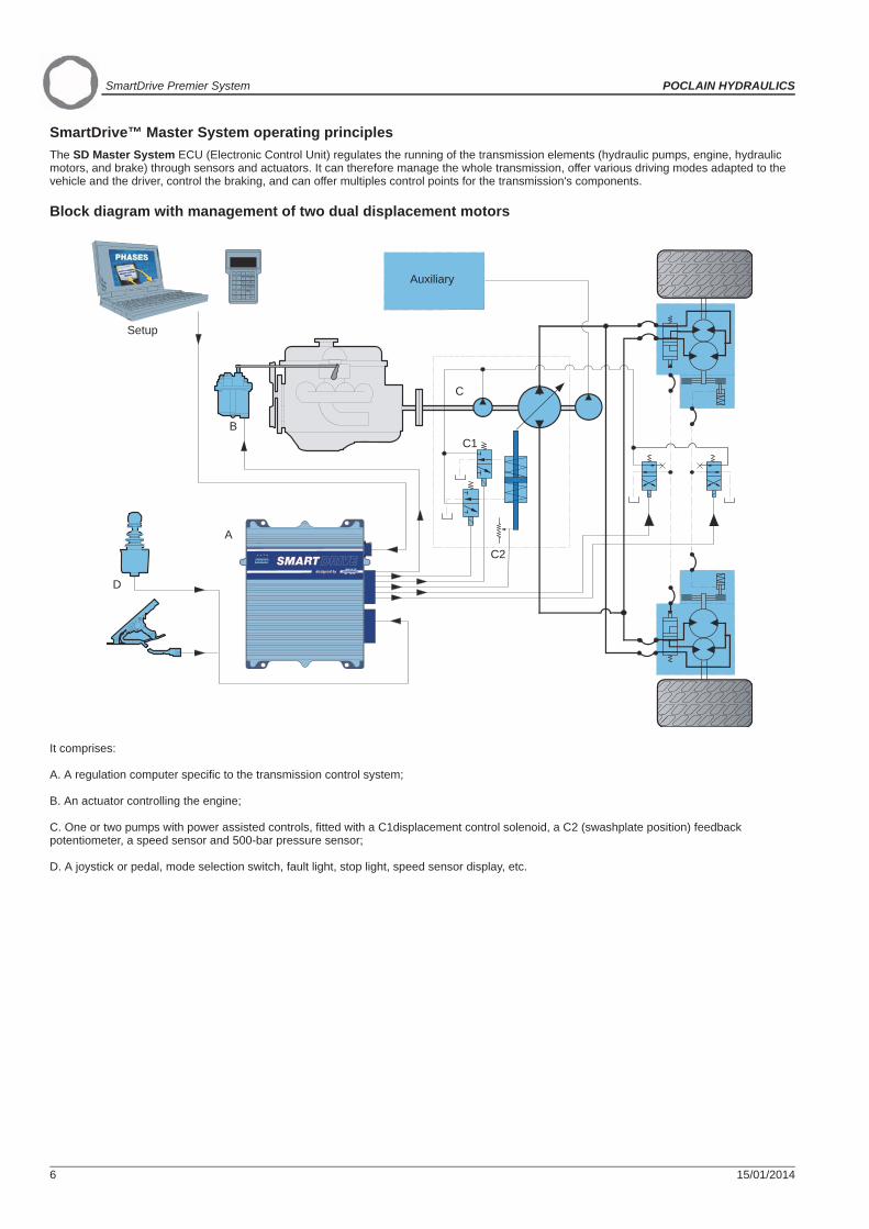
SmartDrive™ Master System operating principlesThe SD Master System ECU (Electronic Control Unit) regulates the running of the transmission elements (hydraulic pumps, engine, hydraulic motors, and brake) through sensors and actuators. It can therefore manage the whole transmission, offer various driving modes adapted to the vehicle and the driver, control the braking, and can offer multiples control points for the transmission's components.
Block diagram with management of two dual displacement motors
It comprises:
A. A regulation computer specific to the transmission control system;
B. An actuator controlling the engine;
C. One or two pumps with power assisted controls, fitted with a C1displacement control solenoid, a C2 (swashplate position) feedback potentiometer, a speed sensor and 500-bar pressure sensor;
D. A joystick or pedal, mode selection switch, fault light, stop light, speed sensor display, etc.
Auxiliary
Setup
B
A
D
C
C1
C2

POCLAIN HYDRAULICS SmartDrive Premier System
15/01/2014 7
Acc
esso
ries
Cha
ract
eris
tics
Inst
alla
tion
SYSTEM MAIN CHARACTERISTICSSmartDrive™Off-Road System main characteristics
Examples of parametersMechanical parameters specific to the machine• Wheel circumference, type of the turn detection, Turn angle, wheel track, etc…• Parameters setting according to the application (3 levels of access authorization : user, manufacturer, expert)• Regulation activation, minimum and maximum action speed, number of wheel to regulate, etc…
Description CharacteriticsNumber of wheels controlled by the system 2 to 4Number of steering wheels or articulated machine 2 to 4Number of wheels controlled by one valve 1 to 2Maximum flow regulated per wheel 50 l/mn [13.2 GPM]Maximum flow without regulation per wheel 120 l/mn [31.7 GPM]Maximum turn detectors range ± 90°
Supply voltage12 VCC24 VCC
Hydraulic circuit maximum pressure 450 bar [6500 PSI]Type of use High pressure (heavy duty)Operation temperature 25 °C à 70 °C [-13 °F to 158 °F]Oil temperature -10 °C à 100 °C [14 °F to 212 °F]
FeaturesTraction control of each wheel by the electro-hydraulic systemDigital measurement of wheel speed (possible use of CAN bus)Steering angle measurement (optional sensor)
POCLAIN HYDRAULICS also offers the hydraulic synchro-nized transmission system using torque transfer,MS mo-tors with TWINLOCK™
SmartDrive Premier System POCLAIN HYDRAULICS
8 15/01/2014
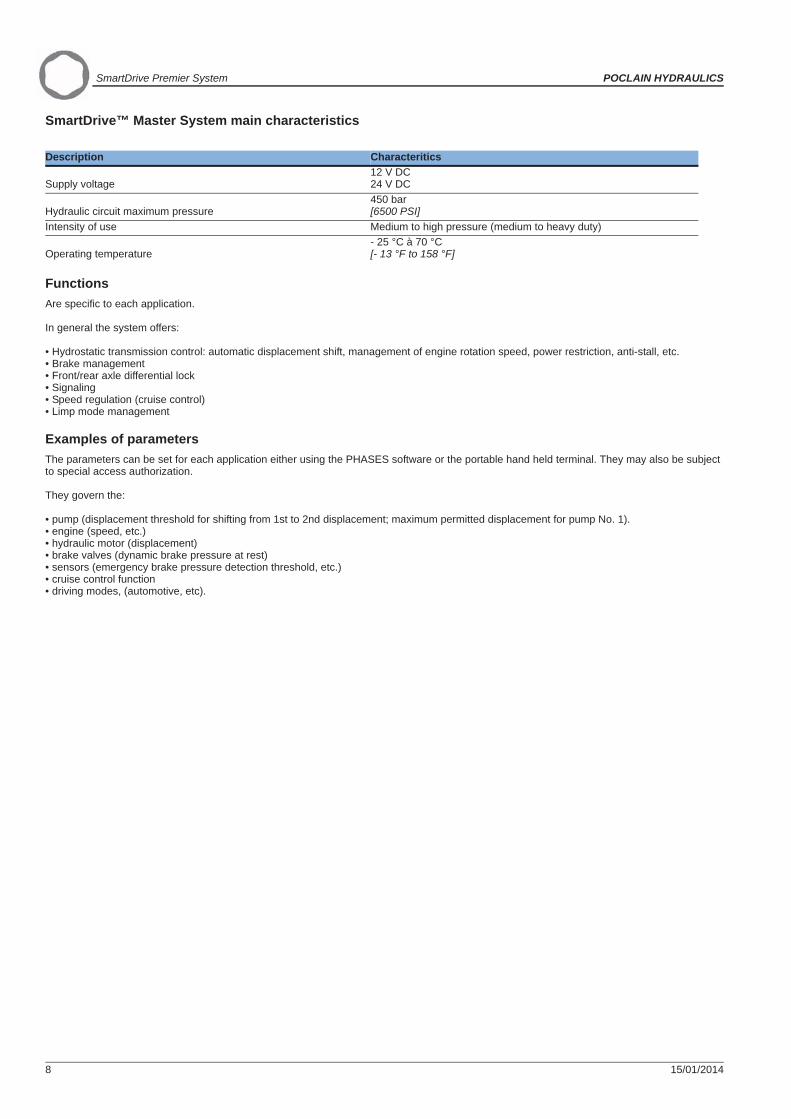
SmartDrive™ Master System main characteristics
FunctionsAre specific to each application.
In general the system offers:
• Hydrostatic transmission control: automatic displacement shift, management of engine rotation speed, power restriction, anti-stall, etc.• Brake management• Front/rear axle differential lock• Signaling• Speed regulation (cruise control)• Limp mode management
Examples of parametersThe parameters can be set for each application either using the PHASES software or the portable hand held terminal. They may also be subject to special access authorization.
They govern the:
• pump (displacement threshold for shifting from 1st to 2nd displacement; maximum permitted displacement for pump No. 1).• engine (speed, etc.)• hydraulic motor (displacement)• brake valves (dynamic brake pressure at rest)• sensors (emergency brake pressure detection threshold, etc.)• cruise control function• driving modes, (automotive, etc).
Description Characteritics
Supply voltage12 V DC24 V DC
Hydraulic circuit maximum pressure450 bar[6500 PSI]
Intensity of use Medium to high pressure (medium to heavy duty)
Operating temperature- 25 °C à 70 °C[- 13 °F to 158 °F]

POCLAIN HYDRAULICS SmartDrive Premier System
15/01/2014 9
Acc
esso
ries
Cha
ract
eris
tics
Inst
alla
tion
SMARTDRIVE™ OFF-ROAD SYSTEM DIAGRAM OF WORKING PRINCIPLES
The SmartDrive™ Off-Road System consists of the following components:
(a)One control regulating computer dedicated to the traction control system;(b)One double regulating valve providing regulation of the input flow of the two motors on the same axle;(c)1 or 2 turn detectors (potentiometer or On/Off sensor);
(d)One speed sensor which must be installed on each regulated motor;(e)Switch (on/off), operation warning light, speed display…
To obtain optimum traction control in turns POCLAIN HY-DRAULICS recommends to use a potentiometer turn de-tector.
POCLAIN HYDRAULICS hydraulic motors used with the SmartDrive™ Off-Road System must be installed with motor equipped with speed sensor or speed sensor pre-disposition. (see speed sensor §).
Front right Rear right
Front left Rear left

SmartDrive Premier System POCLAIN HYDRAULICS
10 15/01/2014
SMARTDRIVE™ MASTER SYSTEM DESCRIPTION OF FUNCTIONS
Driving modesWith agricultural machinery, the driver can have two operating configurations as standard:
[ Road Mode ]
This is an automotive type of driving, similar to an automatic transmission. The transmission ratio is established automatically by the load management of the engine, pump displacement and hydraulic motor displacement. The load on the engine is therefore related to the vehicle speed, enabling pollution and fuel consumption to be reduced.
[ Field Mode ]
The load on the engine is constant; the auxiliary tools consume the majority of its power.
Hence these ground drive defining parameters may be different from one [ Field Mode ] to another. The operational design specifications book for the vehicle transmission sets these parameters.
Shifting between modes is done under different safety conditions managed by the SD Master ECU: for example a sprayer can only shift to [ Road Mode ] if the spray bars are folded back.
For a forklift truck type application, we can distinguish other driving modes:
• [ Mode 1 ]: for novice forklift drivers: driving with safety features (limited max speed, lower acceleration rate, etc.)• [ Mode 3 ]: for experienced forklift drivers: driving is more responsive and reactive (rapid acceleration).• [Inching Mode ]: simultaneous application of the brake and accelerator pedals produces an inching effect (hydraulic clutch control that enables
slow movement independent of the engine load).
Machine transmission control
Automatic displacement shift
A SmartDrive™ Master System transmission varies speed continually.Depending on the acceleration or brake settings issued by the driver, hydraulic motor displacement shift is surge-free. This is accomplished by simultaneous pump displacement control and motor displacement shift control.So since everything takes place nearly automatically, the driver can concentrate on more tasks with greater added value, such as the machine's working functions, and particularly tool management.
Rotation speed management of the engine
The SD Master ECU can integrally manage the engine in two ways:• by means of an actuator• by means of a CAN BusThe ECU optimizes the rotation speed of the engine for the requested power level.
Anti-stall function
In [ Field Mode ], this function reduces the pump speed to prevent the engine stalling if the power required by the hydrostatic transmission exceeds the engine's available power.
Limitation of ground drive power
Agricultural machinery has engines which are generally oversize for the ground drive requirements for supplying the power needed for the on-board tools in [ Field Mode ].In [ Road Mode ], there is no protection; the engine's full power is available. Limiting the integrated power in a transmission controlled by a SmartDrive™ Master System therefore protects the hydrostatic transmission from possible excess output, which could cause irreversible damage over time.
Detection of pump fluid contaminationThe SmartDrive™ Master ECU is capable of detecting possible oil contamination by using the pump feedback control and a potentiometer that tells it the position of the pump's cam casing swashplate. This element protects against malfunctions caused by pump displacement shifts.
It is possible to define other modes, depending on the nature of the work to be carried out and the environment.

POCLAIN HYDRAULICS SmartDrive Premier System
15/01/2014 11
Acc
esso
ries
Cha
ract
eris
tics
Inst
alla
tion
Brake management
Service brake (dynamic)
The brake pedal:• activates mechanical braking,• reduces the pump displacement via the SmartDrive™ Master ECU.
The braking system is of the combined type, i.e. the mechanical braking torque combines with the hydrostatic transmission's braking torque (pump speed reduced).The SmartDrive™ Master System manages the pump and hydraulic motor displacement reduction by taking account of the level of mechanical braking, so that the hydrostatic transmission prevents possible wheel lock.
Parking brake
The parking brake is held by the spring force.To deactivate this brake, the driver activates either a switch, a lever or a foot control. These components then transmit pressure to the brake pistons, which overcome the spring force.
Emergency stop
If the parking brake switch is activated for an emergency stop, the mechanical parking brakes and the hydrostatic brake engage by means of a pump displacement ramp managed by the Smart Drive™ Master System.
Front/rear axle differential lockThis function is available for transmissions fitted with four hydraulic motors and a PW tandem pump.
In [ Field Mode ], it isolates the hydraulic circuits of each front and rear axle using an electro-hydraulic valve.
Speed regulation or "Cruise control"When using the machine for field operations, the driver may require a regulated constant ground drive speed. There are two possible arrangements:
1 - The operator depresses a push button that activates the "Cruise Control" function.At that moment, the traveling speed of the machine is taken as a reference. The ECU manipulates the pump speed setting to maintain the desired speed. The "Cruise Control" function can be overridden by depressing either the brake pedal or a button.
2 - The driver programs in the max speed to be reached in this "Cruise Control" function using the push buttons.The rest of the operating principle is the same as the 1st instance.The max programmed speed will then be attained for the joystick entire stroke (the control lever for the pump displacement).

SmartDrive Premier System POCLAIN HYDRAULICS
12 15/01/2014
Constant speed with combined auxiliary control
In [ Field Mode ], the machine's ground drive speed remains constant in spite of the acceleration of the engine required to the auxiliary functions.The operator, now freed from controlling the speed, can concentrate on tasks with higher added value.
Example of driving position and types of information sent to SmartDrive™ Master
SignalingThe ECU manages the signaling (braking, reverse lights, warning beep, etc.) depending on the ground drive condition.
Limp mode managementDepending on possible faults with the transmission, various operations are possible in degraded mode, to enable minimal ground drive.These degraded modes may be defined in certain cases by agreement with the manufacturer.
CAN Bus communicationThe ECU presents a standard 2.0A or the applied 2.0B CAN interface.When connected to the machine's CAN network, the SmartDrive™ Master ECU can therefore:• Receive messages (engine setting, joystick, selectors, etc.)• Send messages (signaling, fault indicator, error message, etc.)
CAN customization requires major configuration in terms of the complexity of the architecture of the CAN for each manufacturer.Please consult your POCLAIN HYDRAULICS sales engineer.
Options
Cruise control
Parking brake
Controls
Engine load
Pumppressure
Pumpspeed
Stop
Default
Emergency stop
Acceleration / Deceleration
Hydraulic braking
Brake
Hydraulic motor speed
Motor displacement shift
Pre
ssur
e
Spee
d
Pump displacement control

POCLAIN HYDRAULICS SmartDrive Premier System
15/01/2014 13
Acc
esso
ries
Cha
ract
eris
tics
Inst
alla
tion
SMARTDRIVE™ ECU
Commercial name SD Off-Road box SD Master box SD Premier boxPart number 001142255G 001142254F A11999S
FeaturesMaterial AluminiumMass 1.850 kg [4.07 lb]
Operating temperature -25 °C to 70 °C[-13 °F to 158 °F]
Mounting 4 x Ø 7 mm 4 x [0.28 dia.]
Protection index of ECU with its connectors IP65 (weather proof)Electricity supply 12 V cc - 24 V ccCurrent 8 A 14A 20AElectrical protection Excess voltage, Inverter PolarityMicroprocessor 16 bitsMicroprocessor frequency 20 MHzECU setup with a PC or setup terminal
Electromagnetic compatibility
• CISPR 25 : Measure of electromagnetic and radiated emissions.• NF R 13-004-3 : Susceptibility to the radiations of electric fields.• ISO 7637 : Immunity to transitory overvoltages.• ISO/CD 10605 : Immunity to electrostatic discharges• e marking (Directive 2009/19/EC)
Associated software
The control software is adjusted for each application (see p.18). The software can be customized for each application. Poclain Hydraulics recommends that you consult your sales engineer.Setting parametersYou can set parameters either by a hand held terminal or by an software called PHASESTM . See page 18.
ACCESSORIES

SmartDrive Premier System POCLAIN HYDRAULICS
14 15/01/2014
Layout of SmartDrive™ Premier box
InstallationChassis fixing
Quantity Class N.m [lb.ft] ± 10 %M 6 4 8.8 10±1 [7.37±0.73]
Electrical connectionsWhen wiring, check that the wire can nei-ther be cut off, nor torn off when the ma-chine is working or moving.
Communication connector COM-SD-CONNECTOR-PLUGMain connector KIT-CONNECTOR-MAIN-SD
SmartDriveTM Master cable (1 m) CABLE-SD-MASTER-56-1000SmartDriveTM Master cable (5 m) CABLE-SD-MASTER-56-5000SmartDriveTM Off-Road cable (1 m) CABLE-SD-OFFROAD-56-1000SmartDriveTM Off-Road cable (5 m) CABLE-SD-OFFROAD-56-5000Communication cable (1m) COM-CABLE-SD-1000Communication cable (5m) COM-CABLE-SD-5000

POCLAIN HYDRAULICS SmartDrive Premier System
15/01/2014 15
Acc
esso
ries
Cha
ract
eris
tics
Inst
alla
tion
INPUT / OUTPUT CHARACTERISTICS
On-Off digital inputs (x 15)The sensors read are NPN.Description Min. Max.Maximum current for pressure switch digital input(pin 5, 6, 7 on SmartDrive Master connector) - 54 mA
Maximum current for other digital input - 12 mA
Analog inputs (x 11)Description Min. Max.Measurement range 0 V 5 VAccuracy - 1 %Input impedance 100 k
Frequency inputs (x 4)The sensors read can be NPN and PUSH/PULL.Description Min. Max.Measurement range 0 Hz 1,5 kHzMaximum voltage for a low level - 1,5 VMinimum voltage for a high level 8 V -
Differential frequency inputs (x 1)The sensors read can be PUSH/PULL and variable reluctance.For PUSH/PULL sensor only Freq (+) has to be connected.Description Min. Max.Measurement range 0 Hz 8,5 kHzMaximum voltage for a low level for PUSH/PULL sensor - 1,5 VMinimum voltage for a high level for PUSH/PULL sensor 8 V -Minimum peak to peak voltage for variable reluctance sensor 500 mV -
Digital outputs (x 10)Description Min. Max.
Maximum current - 0,5 A under 12 V 0,25 A under 24 V
Output voltage Vbat - 1 V Vbat
PWM outputs dedicated to pumps with SA control (x 2)Description Min. Max.
Maximum current - 2,4 A under 12 V1,2 A under 24 V
Frequency PWM - 10 kHz
Analog PWM outputs (x 4)These outputs are protected against short circuits and overvoltages.Description Min. Max.
Maximum current - 1,5 A under 12 V0,75 A under 24 V
Frequency PWM 80 Hz 100 Hz

SmartDrive Premier System POCLAIN HYDRAULICS
16 15/01/2014
Digital PWM outputs (x 4)These outputs are protected against overvoltages.Description Min. Max.
Maximum current 0 2 A under 12 V1 A under 24 V
H bridge outputs (x 1)Description Min. Max.Maximum current - 3 AMaximum output voltage - VbatFrequency PWM 61 Hz 300 Hz
Sensors power supply 5 VDescription Min. Max.Maximum current - 200 mAOutput voltage 4,90 V 5,10 V
Sensors power supply 12 VDescription Min. Max.Maximum current - 200 mAOutput voltage if Vbat > 13,25 V 11,50 V 12,50 VOutput voltage if Vbat < 13,25 V Vbat - 0,75 V
POCLAIN HYDRAULICS SmartDrive Premier System
15/01/2014 17
Acc
esso
ries
Cha
ract
eris
tics
Inst
alla
tion
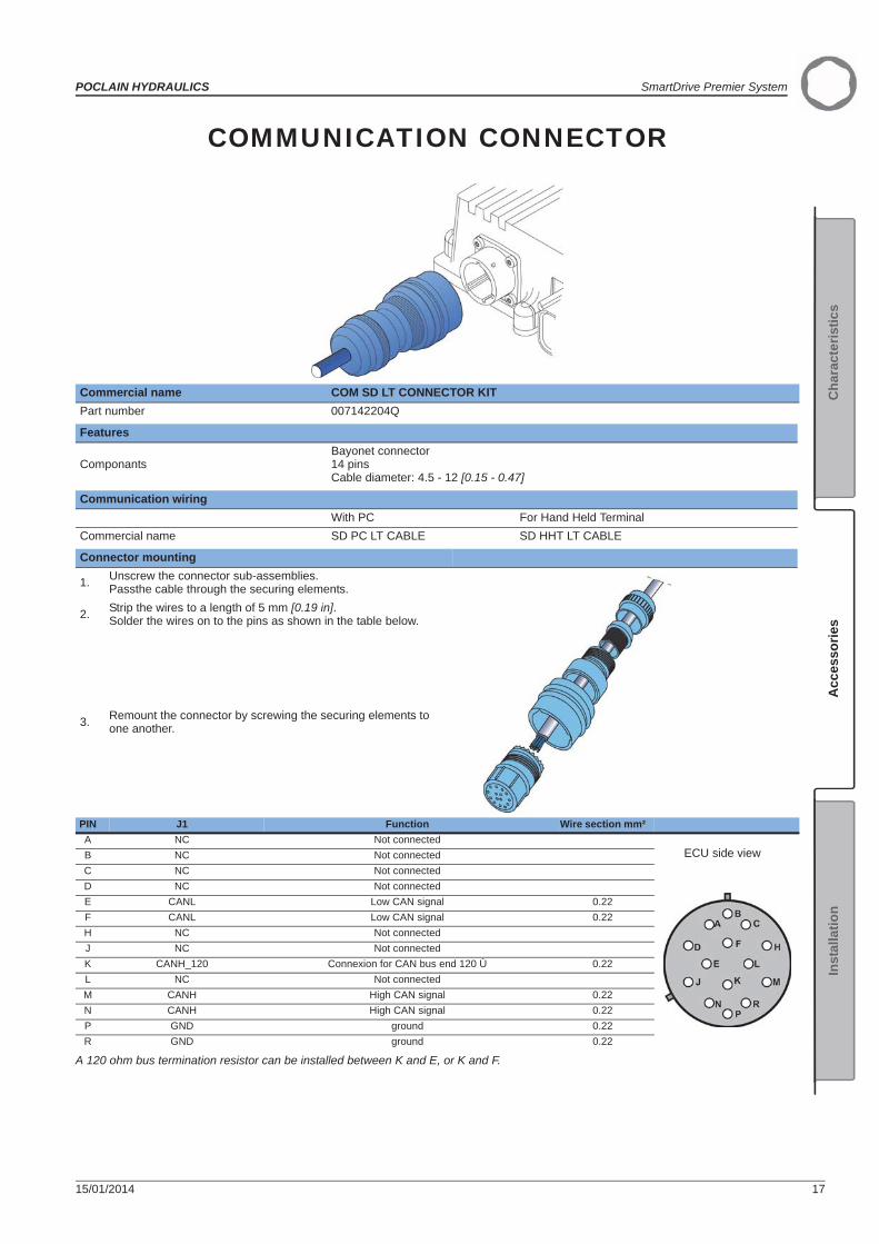
COMMUNICATION CONNECTOR
A 120 ohm bus termination resistor can be installed between K and E, or K and F.
Commercial name COM SD LT CONNECTOR KITPart number 007142204Q
Features
ComponantsBayonet connector14 pinsCable diameter: 4.5 - 12 [0.15 - 0.47]
Communication wiringWith PC For Hand Held Terminal
Commercial name SD PC LT CABLE SD HHT LT CABLE
Connector mounting
1. Unscrew the connector sub-assemblies. Passthe cable through the securing elements.
2. Strip the wires to a length of 5 mm [0.19 in]. Solder the wires on to the pins as shown in the table below.
3. Remount the connector by screwing the securing elements to one another.
PIN J1 Function Wire section mm²A NC Not connected
ECU side viewB NC Not connectedC NC Not connectedD NC Not connectedE CANL Low CAN signal 0.22F CANL Low CAN signal 0.22H NC Not connectedJ NC Not connectedK CANH_120 Connexion for CAN bus end 120 Ù 0.22L NC Not connectedM CANH High CAN signal 0.22N CANH High CAN signal 0.22P GND ground 0.22R GND ground 0.22

SmartDrive Premier System POCLAIN HYDRAULICS
18 15/01/2014
SMARTDRIVE™ COMMUNICATION CABLE
Commercial name COM-CABLE-SD-1000 COM-CABLE-SD-5000Part number A20360F A20361GFunction Connect a SmartDriveTM ECU communication elements to the machine wiring.Compatibility Electronic transmission management with SmartDriveTM ECU.FeaturesLenght of cable 1m 5mMaterial PVCNumber of wires 14Sections of wires 0.22mm2
Layout
Electrical wiringPin Wire
A WhiteB BrownC GreenD YellowE GrayF PinkH BlueJ RedK BlackL VioletM Gray/PinkN Red/BlueP White/GreenR Brown/Green
or

POCLAIN HYDRAULICS SmartDrive Premier System
15/01/2014 19
Acc
esso
ries
Cha
ract
eris
tics
Inst
alla
tion
56-PIN MAIN CONNECTOR
Commercial name MAIN SD CONNECTOR KITPart number 007142203P
Features
Components
Connectors: 211PC562S0008Locking cam: 211A567007Protective cover: 211A560008Pins: 211CC2S1120 (x60)Stoppers (when a pin is not used): 210A015019 (x60)
Protection index IP 68Cable section 0.35 to 2 mm² [0.0005 to 0.003 in²]
Fitting the main connectorLocking device position
A.Place the black unit on the ECU. Note its position and separate its from the ECU.
B.
Insert the purple locking device into the unit from the botton to the top and push until it clicks. The cable will have to be positioned on the locking device side.
Fitting the connector1. Unclip the 2 yellow supports.2. Remove these supports.
3. Turn the unit over.

SmartDrive Premier System POCLAIN HYDRAULICS
20 15/01/2014
4.Strip the wire over 4 mm. Crimp each conductor on its lug using pliers FCI211S005.
5.
Insert each lug into the connector as shown in the electrical circuit diagram in the appendix. In case of error, use extraction tool 2105048 to remove the lug.
6. Insert the green plugs into the free ports of the connector.
7. Clip on the 2 yellow supports.
8.Position the cover and lower it. The cover tab (A) must be on the right of the unit tab (B).
9. Lock it by pulling on it until there is a click.
10. Secure the cable uising a cable grip.Removing the locking device12. To remove the purple locking device, press as shown.13. Partially pull out the locking device, press as shown.
14.Repeat point 12 on the other side, and completely remove the locking device.
Fitting the main connector

POCLAIN HYDRAULICS SmartDrive Premier System
15/01/2014 21
Acc
esso
ries
Cha
ract
eris
tics
Inst
alla
tion
SMARTDRIVE™ MASTER CABLE
Commercial name CABLE-SD-MASTER-56-1000 CABLE-SD-MASTER-56-5000Part number A20309A A20310BFunction Connect a SmartDriveTM Master ECU or a SmartDriveTM Premier ECU (J1) to the
machine wiring.Compatibility Electronic transmission management with SmartDriveTM Master ECU or
SmartDriveTM Premier ECU.FeaturesLenght of cable 1m 5mMaterial PVCNumber of wires 56Sections of wires 1mm2
Layout
Electrical wiring
The wires of the cable are numbered.Pin Wire
1 12 23 3
55 5556 green/yellow
or
. . .
. . .
. . .
. . .

SmartDrive Premier System POCLAIN HYDRAULICS
22 15/01/2014
SMARTDRIVE™ OFF-ROAD CABLE
Commercial name CABLE-SD-OFFROAD-56-1000 CABLE-SD-OFFROAD-56-5000Part number A22473C A22475EFunction Connect a SmartDriveTM Off-Road ECU or a SmartDriveTM Premier ECU (J2) to
the machine wiring.Compatibility Electronic transmission management with SmartDriveTM Off-Road ECU or
SmartDriveTM Premier ECU.FeaturesLenght of cable 1m 5mMaterial PVCNumber of wires 56Sections of wires 1mm2
Layout
Electrical wiring
The wires of the cable are numbered.Pin Wire
1 12 23 3
55 5556 green/yellow
or
. . .
. . .
. . .
. . .

POCLAIN HYDRAULICS SmartDrive Premier System
15/01/2014 23
Acc
esso
ries
Cha
ract
eris
tics
Inst
alla
tion
TRACTION CONTROL (IN-LINE) VALVE
Flow / voltageQ < 20 l/min [5.2 GPM] 20 [5.2 GPM] < Q < 50 l/min [13.2 GPM]12 V 24 V 12 V 24 V
Commercial name VMA-020-T1-12-00 VMA-020-T1-24-00 VMA-050-T1-12-00 VMA-050-T1-24-00Part number 004843325J 004843348J 004843326K 004843347HFunction Proportional Flow Control Valve used to regulate a control wheel slipCompatibility Electronic transmission management
Hydraulic symbol
Pressure loss
The valves must be supplied at G with a pressure of between 15 and 30 bars [217 PSI and 435 PSI].Maximum flow, from P to A or B, for a fully open valve, is 120 l/min [31.7 GPM] per wheel with a pressure difference ( P) of 5 bars [72 PSI] (96 cSt mineral oil at 25 °C [77 °F]).
P ba
r
P [P
SI]

SmartDrive Premier System POCLAIN HYDRAULICS
24 15/01/2014
Layout
Installation• Block position when fixing Horizontal.• Chassis fixing
Ref. Quantity Class N.m [lb.ft] ± 10 % (as per standard DIN 912)
M 10 2 8.8 49 [36]
Motor and valve drain piping must be connected directly to the tank.
Hydraulic connections
Port Function ConnectionMax pressurebar [PSI] N.m [lb.ft] ± 10 %
P HP connection Bride DN 25 PN 400 450 [6000] 90 [66]A-B HP connection M 27 x 2 450 [6000] 200 [148]F Drain M 14 x 1.5 1 [14] 45 [33]G LP supply M 14 x 1.5 15 [217] P < 30 [435] 45 [33]M1-M2 Pressure measurement M 14 x 1.5 0 P < 20 bar [290] 45 [33]
Electrical connections on E1 and E2:
1
POCLAIN HYDRAULICS SmartDrive Premier System
15/01/2014 25
Acc
esso
ries
Cha
ract
eris
tics
Inst
alla
tion
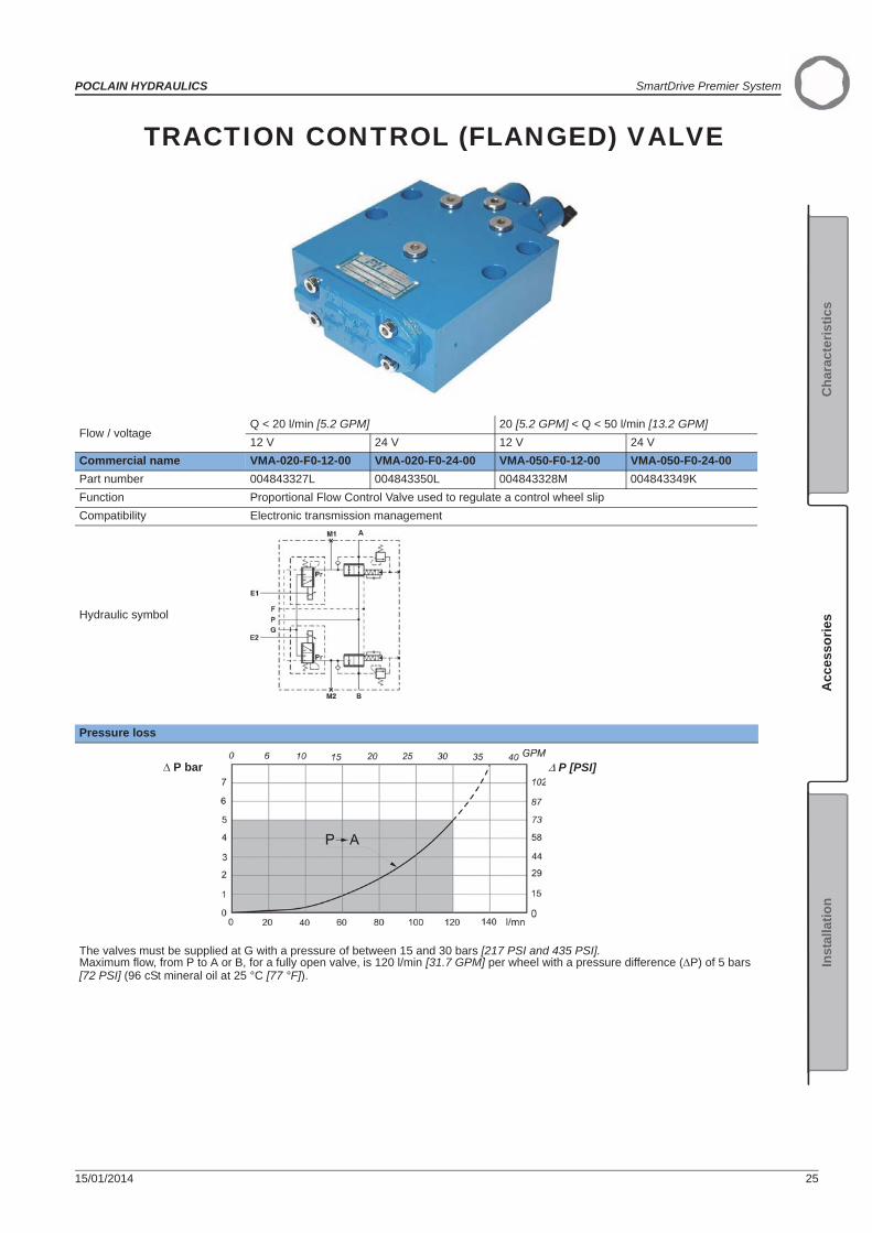
TRACTION CONTROL (FLANGED) VALVE
Flow / voltageQ < 20 l/min [5.2 GPM] 20 [5.2 GPM] < Q < 50 l/min [13.2 GPM]12 V 24 V 12 V 24 V
Commercial name VMA-020-F0-12-00 VMA-020-F0-24-00 VMA-050-F0-12-00 VMA-050-F0-24-00Part number 004843327L 004843350L 004843328M 004843349KFunction Proportional Flow Control Valve used to regulate a control wheel slipCompatibility Electronic transmission management
Hydraulic symbol
Pressure loss
The valves must be supplied at G with a pressure of between 15 and 30 bars [217 PSI and 435 PSI].Maximum flow, from P to A or B, for a fully open valve, is 120 l/min [31.7 GPM] per wheel with a pressure difference ( P) of 5 bars [72 PSI] (96 cSt mineral oil at 25 °C [77 °F]).
P bar P [PSI]

SmartDrive Premier System POCLAIN HYDRAULICS
26 15/01/2014
Layout
InstallationBlock position when fixing Horizontal.
Make sure that the mounting face is clean with no grease.
Remove the protective plate.
Make sure that the O-rings are correctly positioned.
Install the valve on the mounting face with the help of the lug.
Chassis fixing
Quantity Class N.m [lb.ft] ± 10 % (as per standard DIN 912)
M12 4 8.8 86 [63.5]
Hydraulic connections
Port Function Connection Max pressure bar [PSI] N.m [lb.ft] ± 10 %
P HP connection Bride DN 25 PN 400 450 [6000] 90 [66]A-B HP connection M 27 x 2 450 [6000] 200 [148]F Drain M 14 x 1.5 1 [14] 45 [33]G LP supply M 14 x 1.5 15 [217] P < 30 [435] 45 [33]M1-M2 Pressure measurement M 14 x 1.5 0 P < 20 bar [290] 45 [33]
Electrical connections on E1 and E2:
Motor and valve drain piping must be connected directly to the tank.
POCLAIN HYDRAULICS SmartDrive Premier System
15/01/2014 27
Acc
esso
ries
Cha
ract
eris
tics
Inst
alla
tion
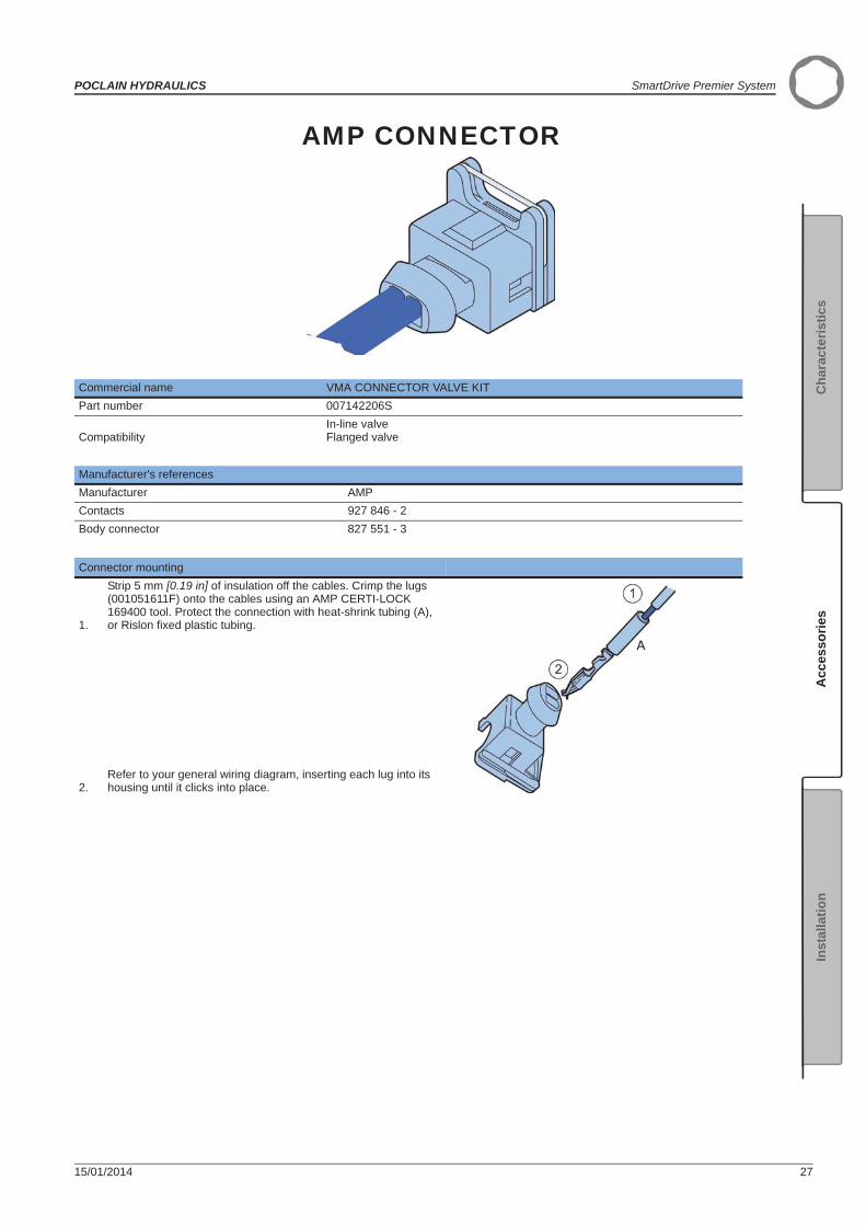
AMP CONNECTOR
Commercial name VMA CONNECTOR VALVE KITPart number 007142206S
CompatibilityIn-line valveFlanged valve
Manufacturer's referencesManufacturer AMPContacts 927 846 - 2Body connector 827 551 - 3
Connector mounting
1.
Strip 5 mm [0.19 in] of insulation off the cables. Crimp the lugs (001051611F) onto the cables using an AMP CERTI-LOCK 169400 tool. Protect the connection with heat-shrink tubing (A), or Rislon fixed plastic tubing.
2.Refer to your general wiring diagram, inserting each lug into its housing until it clicks into place.

SmartDrive Premier System POCLAIN HYDRAULICS
28 15/01/2014
SPEED SENSOR T4
(*) : According to the size of the motor, consult your Poclain Hydraulics sales engineer
Commercial name T4 SENSOR 12-44 T4 SENSOR 12-53 T4 SENSOR 12-62Part number A22082C A22083D A22084ELenght L(*) 44 [1.73] 53 [2.09] 62 [2.44]Function Detect movements : rotation speedCompatibility Electronic transmission management
FeaturesMaximum range 1.15 mm [0.045’’]Supply voltage 8 - 30 VCurrent consumption 20 mA max.Output type - 1 push-pull square frequency signal
- Maximum load current: 20 mA- Voltage at low state: < 1.5 V- Voltage at high state: > (power supply voltage - 3.5 V)
Frequency range 0 to 15 kHzOperating temperature - 40°C to + 125°C [- 40°F to 257°F]Protection rating IP68Material Stainless steel
Layout

POCLAIN HYDRAULICS SmartDrive Premier System
15/01/2014 29
Acc
esso
ries
Cha
ract
eris
tics
Inst
alla
tion
InstallationDisconnecting the accessories and speed set upIn the case of motors predisposed to speed, the existing shutter needs to be removed and eliminated before installing the sensor and its attachment device.To install the sensor, see the ''Installation guide'' brochure No. 801478197L.
Connection of the speed sensorRemove the plastic plug on the connector.
Function Pin number
Power supply 1Earth 3Square frequency signal 4
For the connection of connectors, please refer to the connection table and the general cabling plan contained in the installation brochure for your transmission.
Cables for Speed Sensors T4 connectionSales Code Item CodeELEC-CABLE-M12-180°-5000 A07468SELEC-CABLE-M12-90°-5000 A04999J

SmartDrive Premier System POCLAIN HYDRAULICS
30 15/01/2014
M12 CABLE
Commercial name ELEC-CABLE-M12-180°-5000 ELEC-CABLE- M12-90°-5000Part number A07468S A04999JCompatibility Speed sensors and digital sensors.FeaturesLenght of cable 5 mMaterial PURNumber of wires 4Sections of wires 0.34 mm2
Protection IP68
Layout 180° 90°
Connector MountingSecurely hand tighten the cable's ring to sensor connector M12.
Electrical wiringPin Wire1 Brown2 White3 Blue4 Black

POCLAIN HYDRAULICS SmartDrive Premier System
15/01/2014 31
Acc
esso
ries
Cha
ract
eris
tics
Inst
alla
tion
ROTARY POTENTIOMETER
Commercial name ANGULAR-SENSOR-CABLE-MP-WPPart number A13534LFunction Detects movement: Engine operations, lever positions, etc.Compatibility Electronic transmission management
FeaturesResistance 2.5 kType Analog potentiometerTravel 54°Operating temperature - 40 °C to + 85 °C [-40 °F to 185 °F]Weight 230 g [0.5 lb]Protection IP 66
Layout
1
Ø 11.4 [0.45 dia.] right milling 58 teethNorme / Std ANSI/ASME B94.6-1984

SmartDrive Premier System POCLAIN HYDRAULICS
32 15/01/2014
InstallationMechanical fittingThe steering sensor must be fitted onto a rigid plate at least 2 mm [0.08"] thick.If this sensor is used with a Smart Drive™, Off Road or Premier transmission system, it must be linked with a rod to the steering column or pivot. On four-wheel steering machines, a second steering sensor will be necessary.
Ref. Quantity ClassN.m [lb.ft] ± 10
%(as per standard DIN 912)
M 6 2 8.8 10 [7.37]
Example of mounting:
Sensor electrical signal control
ConnectionsCommercial name Part No. Delphi Ref.
007142222K3 terminal connector: 1216 2182Terminal (x4) 1212 4076
Connector mounting
1.Pass the wires through the connector.2.Strip 5 mm from the wires.3.Crimp the terminals with special tool 1203 9500.4.Pull the wires towards the connector to fit the terminals into their housingElectric wiring:
For connections: See the connection table and the main wiring diagram in the installation brochure for your transmission system.
Sensor wire ID FunctionA Supply
B Signal
C Ground
1
Difference min. 1V
Left direction Straight Right direction
Difference min. 1V
>0.4V >4.6V3.6V1.4V
Position 0

POCLAIN HYDRAULICS SmartDrive Premier System
15/01/2014 33
Acc
esso
ries
Cha
ract
eris
tics
Inst
alla
tion
SMARTDRIVE™ PREMIER IDENTIFICATION
A : Model code:e.g. SD PREMIER BOXB : Code (Part number):e.g. 001142257JD : Number (Chronological number):e.g. 7572
Only the calculator and the valves are identified by this model identification plate.
The part number and the chronological order number must be specified to order spare parts.
The dimensions of the components described in this bro-chure, the operation and the CEM chapter are given in the characteristics brochure.
A
B
D
SD PREMIER BOX
001
001142257J
7572

SmartDrive Premier System POCLAIN HYDRAULICS
34 15/01/2014
SMARTDRIVE™ PREMIER LIST OF COMPONENTSSmartDriveTM Off-Road System list of components
Commercial code Part numberRegulating computer Boîtier SD Off-Road 001142255G
Main connector Kit connecteur main SD 007142203P
SmartDriveTM Off-Road cable (1 m) CABLE-SD-OFFROAD-56-1000 A22473C
SmartDriveTM Off-Road cable (5 m) CABLE-SD-OFFROAD-56-5000 A22475E
Communication connector Kit connecteur COM SD LT 007142204Q
Communication cable (1 m) COM-CABLE-SD-1000 A20360F
Communication cable (5 m) COM-CABLE-SD-5000 A20361GPack connectorsWith:4x kit connecteur capt tachy4x kit connecteur valve VMA1x kit connecteur main SD2x kit connecteur capt direct.
Kit connecteur SD Off-Road 007142207T
WiringCâble SD PC LT 006142212S
Câble SD HHT LT 006142213T
«PHASES» software Pack Phases Off-Road 005142207F
Hand held terminal KIT TERMINAL ST2000 005142202A
In-line valves
Q < 20 l/min [5.2 GPM] 12V VMA-020-T1-12-00 004843325J
Q < 20 l/min [5.2 GPM] 24V VMA-020-T1-24-00 004843348J20 [5.2 GPM] < Q < 50 l/min [13.2 GPM] 12V VMA-050-T1-12-00 004843326K20 [5.2 GPM] < Q < 50 l/min [13.2 GPM] 24V VMA-050-T1-24-00 004843347HFlanged valvesQ < 20 l/min [5.2 GPM] 12V VMA-020-F0-12-00 004843327LQ < 20 l/min [5.2 GPM] 24V VMA-020-F0-24-00 004843350L20 [5.2 GPM] < Q < 50 l/min [13.2 GPM] 12V VMA-050-F0-12-00 004843328M20 [5.2 GPM] < Q < 50 l/min [13.2 GPM] 24V VMA-050-F0-24-00 004843349KRegulating valve connector Kit connecteur valve VMA 007142 206S
Speed sensorT4 SENSOR 12-44 A22082CT4 SENSOR 12-53 A22083DT4 SENSOR 12-62 A22084E
M12 cable for speed sensorELEC-CABLE-M12-180°-5000 A07468SELEC-CABLE-M12-90°-5000 A04999J
Rotary potentiometer ANGULAR-SENSOR-CABLE-MP-MW A13534LRotary potentiometer connector KIT CAPT VIRAGE 007142222KDigital sensor (wire) DETECTEUR TOR M18 CABLE 003241160A
Digital sensor (connector) DETECTEUR TOR M18 CONNECT 003241159Z
M12 cable for digital sensor (connector)ELEC-CABLE-M12-90°-5000 A04999JELEC-CABLE-M12-180°-5000 A07468S
Commercial codes and part numbers may change during the lifetime of the system. To have the latest update, please, contact POCLAIN HYDRAULICS.
POCLAIN HYDRAULICS SmartDrive Premier System
15/01/2014 35
Acc
esso
ries
Cha
ract
eris
tics
Inst
alla
tion
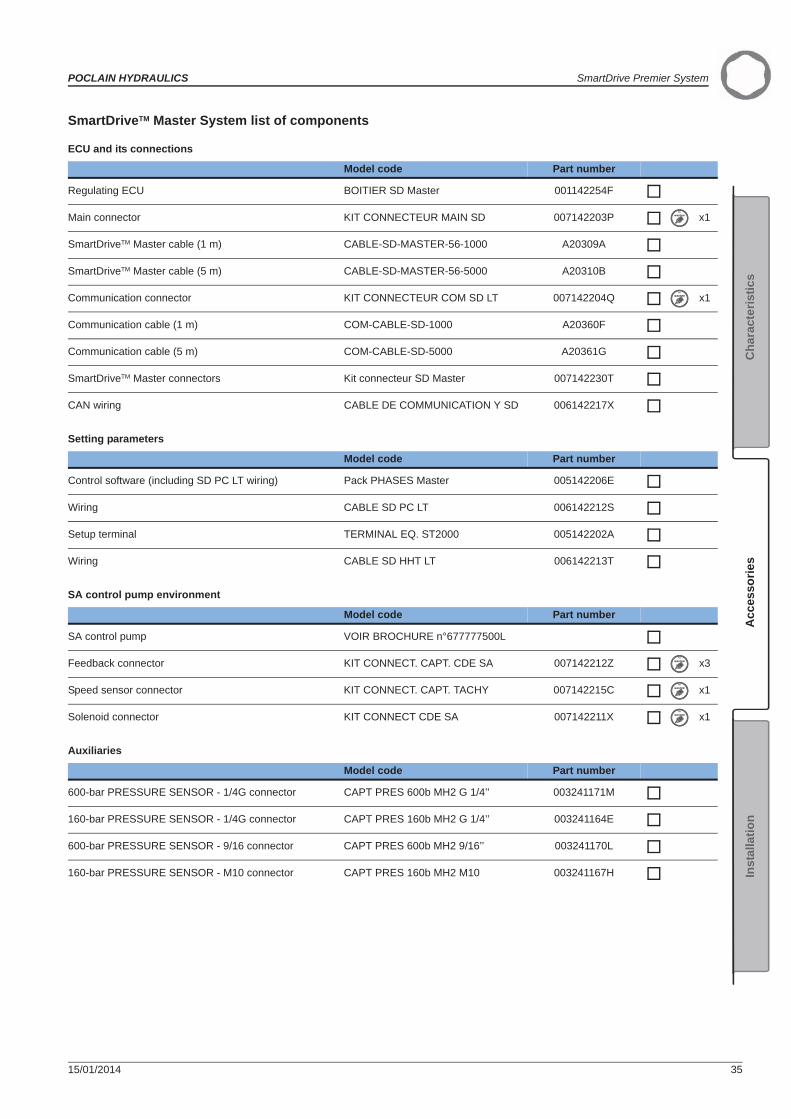
SmartDriveTM Master System list of components
ECU and its connections
Setting parameters
SA control pump environment
Auxiliaries
Model code Part number
Regulating ECU BOITIER SD Master 001142254F
Main connector KIT CONNECTEUR MAIN SD 007142203P x1
SmartDriveTM Master cable (1 m) CABLE-SD-MASTER-56-1000 A20309A
SmartDriveTM Master cable (5 m) CABLE-SD-MASTER-56-5000 A20310B
Communication connector KIT CONNECTEUR COM SD LT 007142204Q x1
Communication cable (1 m) COM-CABLE-SD-1000 A20360F
Communication cable (5 m) COM-CABLE-SD-5000 A20361G
SmartDriveTM Master connectors Kit connecteur SD Master 007142230T
CAN wiring CABLE DE COMMUNICATION Y SD 006142217X
Model code Part number
Control software (including SD PC LT wiring) Pack PHASES Master 005142206E
Wiring CABLE SD PC LT 006142212S
Setup terminal TERMINAL EQ. ST2000 005142202A
Wiring CABLE SD HHT LT 006142213T
Model code Part number
SA control pump VOIR BROCHURE n°677777500L
Feedback connector KIT CONNECT. CAPT. CDE SA 007142212Z x3
Speed sensor connector KIT CONNECT. CAPT. TACHY 007142215C x1
Solenoid connector KIT CONNECT CDE SA 007142211X x1
Model code Part number
600-bar PRESSURE SENSOR - 1/4G connector CAPT PRES 600b MH2 G 1/4’’ 003241171M
160-bar PRESSURE SENSOR - 1/4G connector CAPT PRES 160b MH2 G 1/4’’ 003241164E
600-bar PRESSURE SENSOR - 9/16 connector CAPT PRES 600b MH2 9/16’’ 003241170L
160-bar PRESSURE SENSOR - M10 connector CAPT PRES 160b MH2 M10 003241167H
SmartDrive Premier System POCLAIN HYDRAULICS
36 15/01/2014
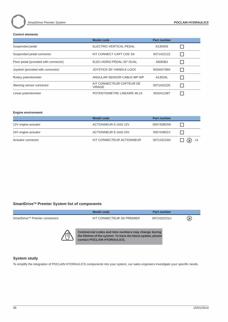
Control elements
Engine environment
Hydraulic motor environment
System studyTo simplify the integration of POCLAIN HYDRAULICS components into your system, our sales engineers investigate your specific needs.
Model code Part number
Suspended pedal ELECTRIC-VERTICAL-PEDAL A13540S
Suspended pedal connector KIT CONNECT CAPT CDE SA 007142212Z
Floor pedal (provided with connector) ELEC-HORIZ-PEDAL-30°-DUAL A50838J
Joystick (provided with connector) JOYSTICK-35°-HANDLE-LOCK 003442799X
Rotary potentiometer ANGULAR-SENSOR-CABLE-MP-WP A13534L
Steering sensor connector KIT CONNECTEUR CAPTEUR DE VIRAGE 007142222K
Linear potentiometer POTENTIOMETRE LINEAIRE ML10 003241108T
Model code Part number
12V engine actuator ACTIONNEUR E GAS 12V 005743902W
24V engine actuator ACTIONNEUR E GAS 24V 005743901V
Actuator connector KIT CONNECTEUR ACTIONNEUR 007142219G x1
Model code Part number
T4 SENSOR 12-44 A22082C
Speed sensor T4 SENSOR 12-53 A22083D
T4 SENSOR 12-62 A22084E
M12 cable for speed sensor ELEC-CABLE-M12-180°-5000 A07468S x1
ELEC-CABLE-M12-90°-5000 A04999J x1
SmartDriveTM Premier System list of components
Model code Part number
SmartDriveTM Premier connectors KIT CONNECTEUR SD PREMIER 0071422231U
Commercial codes and item numbers may change during the lifetime of the system. To have the latest update, please contact POCLAIN HYDRAULICS.

POCLAIN HYDRAULICS SmartDrive Premier System
15/01/2014 37
Acc
esso
ries
Cha
ract
eris
tics
Inst
alla
tion
INSTALLATIONSmartDriveTM Off-Road System installation
Machine safety recommendations
Before installation
• Be sure that the hydraulic system power source (engine) is stopped and that the battery is disconnected. • Do not proceed to installation on a hot or pressurized hydraulic system (accumulators must be purged).
During installation• Some hydraulic components are very heavy. Secure them with a lifting device of adequate capacity when installing on the machine frame.• During handling, protect all interface surfaces from shocks (piloting surfaces, studs, ports, connectors, plugs, etc.)• Ensure cleanliness of piloting and thrust surfaces of components and devices on the chassis before reassembly (no paint).• Never heat hydraulic fluid, as it may flame at high temperature. Some solvents are also flammable.Do not smoke during installation.
Machine wiring recommendations• All the cables must be encased in flexible metal or plastic sheaths;• All cables or sheaths must be held well in place and locked in to prevent pull-ou;• Bring the sheath supports close together;• The sheaths must be able to slide into the anchoring;• Avoid mechanical stresses in the cables;• Do not place the cables or sheaths close to moving or vibrating parts;• Do not lay the sheaths along sharp angles. Protect them at each bend;• Avoid laying the sheaths too close to high heat sources;• Use wires with abrasion-resistant sheaths;• Use cables that resist temperatures between 85°C and 105°C close to heat sources;• Separate power cables from control cables;Pass the cables inside the machine, ensuring as much contact as possible with metal surfaces (steel). This will act as a shield against electromagnetic radiation.
setting parametersThe commissioning involves the downloading of the software and parameters defined by the manufacturer and POCLAIN HYDRAULICS.
However, a customized parameter setting is possible. To set them, use the PHASES Off-Road software or the manual terminal.
The machine manufacturer is responsible for safety measures during the installation of our products. They must comply with applicable laws in the country or state.
Place the machine on the wheel blocks.Set up a safety area. Observe all personnel safety instructions.
Hot or pressurized hydraulic fluid may cause serious burns & infections to the human body. Consult a doctor in case of ac-cident.
INSTALLATION
SmartDrive Premier System POCLAIN HYDRAULICS
38 15/01/2014
Setting by the PHASES Off Road software:Install the PHASES software (see the 801378161B installation guide).Connect the calculator to the PC computer with the CABLE SD PC LT wire by connecting the SUBD9 wire of the PC to the communication connector of the calculator.For more information on the PHASES software, refer to its hot-line.
Setting by the manual terminalThe manual terminal only allows to modify the parameters directly in the calculator. You can't save any configuration under no circumstances.Connect the calculator to the hand handing terminal computer with the CABLE SD HHT LT wire by connecting the RJ11 wire of the HHT to the calculator's communication connector.To parameter the system by the hand held terminal, see the n° A06618T installation guide.
Checking the installation before starting up
Checking• Check that all the valves regulating the wheels hydraulic supply and that the sensors (speed sensor and turn sensor) have been correctly connected to the electrical beam.• Check the electrical wiring.
Hydraulic circuitCheck that the connection of the following components is in conformity with the hydraulic circuit diagram and with their respective installation and commissioning manuals.
• valves;• hydraulic pump;• hydraulic motors.
For further information, see PHASES™ user guide no. 801378161B and hand held terminal user guide no. A06618T.
The elements to be checked depend on the application of each vehicle. Please remember that each manufacturer is ultimately responsible for checking their machinery at the end of the line.
The pressure drop in the hydraulic motor return circuits must not bring the pilot pressure in the valves below 22 bar [319 PSI].
The valve and motor drain piping must be connected di-rectly to the tank.

POCLAIN HYDRAULICS SmartDrive Premier System
15/01/2014 39
Acc
esso
ries
Cha
ract
eris
tics
Inst
alla
tion
SmartDriveTM Master System installation
Machine safety recommendations
Before installation
Be sure that the hydraulic system power source (engine) is stopped and that the battery is disconnected. • Do not proceed to installation on a hot or pressurized hydraulic system (accumulators must be purged).
During installation• Some hydraulic components are very heavy. Secure them with a lifting device of adequate capacity when installing on the machine frame.• During handling, protect all interface surfaces from shocks (piloting surfaces, studs, ports, connectors, plugs, etc.)• Ensure cleanliness of piloting and thrust surfaces of components and devices on the chassis before reassembly (no paint).• Never heat hydraulic fluid, as it may flame at high temperature. Some solvents are also flammable.• Do not smoke during installation.
Machine wiring recommendations.• All the cables must be encased in flexible metal or plastic sheaths;• All cables or sheaths must be held well in place and locked in to prevent pull-ou;• Bring the sheath supports close together;• The sheaths must be able to slide into the anchoring;• Avoid mechanical stresses in the cables;• Do not place the cables or sheaths close to moving or vibrating parts;• Do not lay the sheaths along sharp angles. Protect them at each bend;• Avoid laying the sheaths too close to high heat sources;• Use wires with abrasion-resistant sheaths;• Use cables that resist temperatures between 85°C and 105°C [ 185°F and 221°F ] close to heat sources;• Separate power cables from control cables;Pass the cables inside the machine, ensuring as much contact as possible with metal surfaces (steel). This will act as a shield against electromagnetic radiation.
Parking brake wiring recommendations
The machine manufacturer is responsible for safety measures during the installation of our products. They must comply with applicable laws in the country or state.
Place the machine on the wheel blocks.Set up a safety area. Observe all personnel safety instructions.
Hot or pressurized hydraulic fluid may cause serious burns & infections to the human body. Consult a doctor in case of ac-cident.
If the box controls also the parking brake, you must IMPERATIVELY wire as shown opposite.
Warning: The switch used must-to be able to carry the current which circulates in the solenoid brake.
1- Exit orders parking brake.2- Entry On/Off sensor.3- Solenoid of parking brake (if supplied = brake).4- Switch of parking brake.5- Solenoid relay.
Is possible to use a switch which can not take the current, but that induces 2 constraints:• The diagram should be carried out as shown opposite (switch placed on the pilot circuit of SmartDrive™ Master and Premier).• The driver of the machine cannot operate directly the parking brake, he must make sure that this one is well applied before leaving the machine.

SmartDrive Premier System POCLAIN HYDRAULICS
40 15/01/2014
setting parametersThe commissioning involves the downloading of the software and parameters defined by the manufacturer and POCLAIN HYDRAULICS.However, a customized parameter setting is possible. To set them, use the PHASES Master software or the manual terminal.
Setting by the PHASES software:Install the PHASES software (see the 801378162C installation guide).Connect the calculator to the PC computer with the CABLE SD PC LT wire by connecting the SUBD9 wire of the PC to the communication connector of the calculator.For more information on the PHASES software, refer to its hot-line.
Setting by the manual terminalThe manual terminal only allows to modify the parameters directly in the calculator. You can't save any configuration under no circumstances.Connect the calculator to the hand handing terminal computer with the CABLE SD HHT LT wire by connecting the RJ11 wire of the HHT to the calculator's communication connector.To parameter the system by the hand held terminal, see the n° A06618T installation guide.
Checking the installation before starting up
Checking of the electrical environmentThe PHASES software enables you to view any anomalies detected by the SD Master ECU, by delivering an error code, a brief explanation and a list of possible causes. In particular, it indicates:• short-circuit type electrical anomalies on the ground, or the 5V,• cabling errors: switch allocated/not allocated to a given part,• input/output malfunctions.The portable HHT can also check these points without help files.
Hydraulic circuitCheck that the connection of the following components is in conformity with the hydraulic circuit diagram and with their respective installation and commissioning manuals.• valves;• hydraulic pump;• hydraulic motors.
Verification of hydraulic pump installation (clockwise rotation PV pump)
For further information, see PHASES™ user guide no. 801378162C and hand held terminal user guide no. A06618T.
The elements to be checked depend on the application of each vehicle. Please remember that each manufacturer is ultimately responsible for checking their machinery at the end of the line.
The calibration can detect cable configurations (see next chapter).
The pressure drop in the hydraulic motor return circuits must not bring the pilot pressure in the valves below 20 bar [290 PSI].
The valve and motor drain piping must be connected di-rectly to the tank.
Pump 1 C motor (*) 2 C motor AxlePort A Port R Port R Port LPort B Port L Port A Port R
POCLAIN HYDRAULICS SmartDrive Premier System
15/01/2014 41
Acc
esso
ries
Cha
ract
eris
tics
Inst
alla
tion
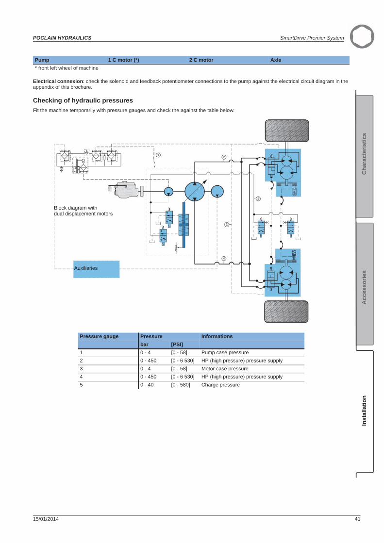
Electrical connexion: check the solenoid and feedback potentiometer connections to the pump against the electrical circuit diagram in the appendix of this brochure.
Checking of hydraulic pressures Fit the machine temporarily with pressure gauges and check the against the table below.
* front left wheel of machine
Pressure gauge Pressure Informationsbar [PSI]
1 0 - 4 [0 - 58] Pump case pressure2 0 - 450 [0 - 6 530] HP (high pressure) pressure supply3 0 - 4 [0 - 58] Motor case pressure4 0 - 450 [0 - 6 530] HP (high pressure) pressure supply5 0 - 40 [0 - 580] Charge pressure
Pump 1 C motor (*) 2 C motor Axle
Auxiliaries
Block diagram with dual displacement motors
SmartDrive Premier System POCLAIN HYDRAULICS
42 15/01/2014
Starting up the engine
Put the F/N/R (Forward/Neutral/Reverse) shift lever in the neutral position. Apply the parking brake.Switch on the ECU.Start the engine, and wait until the charge pressure is established.
Start the engine again and then use the PHASES software in the input/output diagnostic module to check that the readings of the various sensors (switch, potentiometer sensors, etc.) are displayed correctly when you actuate them.
Checking the wiring of the engine actuator (option)When you press on the travel pedal, the actuator must rotate:• Clockwise (as seen from shaft end) for a clockwise connection;• counter-clockwise (as seen from shaft end) for a counter-clockwise connection.Check that the feedback signal from the actuator potentiometer sensor is increasing with voltmeter.
This checking can also be made using the HHT, from the calibration menu. The terminal gives a real-time display of the voltage and the actuator excitement sensor percentage.
Calibrating all the partsThis calibration can be carried out using either PHASES or the HHT. See their respective user manuals.
Activating pump displacementRelease the parking brake.Put the F/N/R shift lever (or switch or joystick) in the Forward Drive position.Gently depress the travel pedal; the wheels must turn slowly forward.
Check the pressure levels.
Checking the system’s specific functions on wheel blocks
The forward/reverse ground drive direction using the joystick or switch.
Return to neutral• Put the gear shift in neutral when in ground drive: the machine will decelerate in accordance with the programmed deceleration ramp.
Reversal• Reverse when in ground drive: the wheels of the machine will decelerate then accelerate in the opposite direction depending on the pedal position.
Braking• Test the parking brake: activating it deactivates the travel pedal.• Test the emergency brake by fully depressing the brake pedal.
Checking that the system works on wheelsRepeat the previous tests (except tests of braking).Test the functions that are specific to your application (anti-stall, cruise control, etc)
Place the machine on the wheel blocks.Set up a safety area. Observe all personnel safety instructions.
Press the emergency stop button and check that it stops the engine and cuts off power to the SD MASTER box.
Limit the wheel rotation speed to 10% of their maximum speed when the machine is on wheel blocks.
A functional check of the parking brake must be carried out each time it is used as an auxiliary brake (or emergency brake). For all vehicles capable of speeds over 25 km/hour, please contact your Poclain Hydraulics application engineer.

POCLAIN HYDRAULICS SmartDrive Premier System
15/01/2014 43
Acc
esso
ries
Cha
ract
eris
tics
Inst
alla
tion
SMARTDRIVE™ OFF-ROAD SYSTEM SETTING PARAMETERS, DOWNLOADING,CALIBRATION, DIAGNOSTICS
Setting parametersThe computer parameters are set at the factory. If the machine characteristics or operating conditions change, the computer parameters of the SmartDrive™ Off-Road System will have to be modified. The POCLAIN HYDRAULICS system includes the setting and analysis PHASES.This tools manage 3 access levels to the parameters according to the user's skills:• Service;• Manufacturer;• Expert.
Loading dataUsing a PC and the PHASES software allows you to:• Save the configuration;• Load the configuration.The hand held terminal allows you to modify the data item per item (see the brochure n° 801478140Z).
CalibrationThe parameter software allows to calibrate the minimum, maximum and neutral positions of the potentiometer sensors installed on the machine in order to optimize the system's operation.
DiagnosticsThe SmartDrive™ Off-Road System contains 2 feed back sources :• Level 1: The regulating computer shows that the system is functioning properly using 4 LED (red/green) on the front panel.• Level 2 : The PHASES software allows the user to download the system's operation data. The collected data will permit to identify a possible malfunction.The hand held terminal allows to analyze a malfunction by a mistake code.
Any modification of the parameters must be carried out by an engineer trained and approved by the machine manu-facturer.The POCLAIN HYDRAULICS technical support team can assist you in defining your parameters.

SmartDrive Premier System POCLAIN HYDRAULICS
44 15/01/2014
FIRST LEVEL DIAGNOSTICSmartDriveTM Off-Road System first level diagnostic
Dash-board indicator light:
The system operation light is off if the system is deactivated, on if the system is active and blinks if there's a malfunction.
Warning lights on the box front face:
They shows the system state in real time.
• The green warning lights blink following the wheels rotation.
• Fixed orange or red warning lights show a malfunction in the system. The malfunction is identified by a mistake code. See the following codes table to identify the problem.
1 2 3 4 Defaults Error code
No default -
Rear right wheel speed 8
Rear left wheel speed 7
Front right wheel speed 6
Front left wheel speed 5
Rear right solenoid valve 12
Rear left solenoid valve 11
Front right solenoid valve 10
Front left solenoid valve 9
Turn sensor 2 14
Turn sensor 1 13
5V supply 4
12V supply 3
Low battery power 2
Battery overpower 1
Warning lamp 15

POCLAIN HYDRAULICS SmartDrive Premier System
15/01/2014 45
Acc
esso
ries
Cha
ract
eris
tics
Inst
alla
tion
SmartDriveTM Master System first level diagnostic
Fault warning lamp on dashboard:The warning lamp flashes in the event of a fault.Otherwise, it remains unlit.
Indicator lights on the box front face:These indicate the system status in real time.• If the vehicle is fit with a speed sensor, the green indicator lights flash at the wheel rotation frequency, enabling a diagnostic on this motors' speed sensor.• The indicator lights, orange if the vehicle is traveling or red if the vehicle is stationary, indicate a system failure. The malfunction is identified by an error code, represented in the table below.
1 2 3 4 Defaults Error code
No default -
5V supply 4
12V supply 3
Low battery power 2
Battery overpower 1
Warning lamp 15

SmartDrive Premier System POCLAIN HYDRAULICS
46 15/01/2014
APPENDIXSmartDriveTM Off-Road System appendix
Electrical wiring
1 502 E 110 Q 132 552 E 110 Q 143 503 J 150 Q 414 553 J 150 Q 425 504 J 201 G 356 554 J 202 H 3611 601 M 211 G
4313 110 Q 212 H14 110 Q 251 G
1515 251 G 252 H15 252 H 401 D 4916 411 D 402 F 5116 412 F 403 I 5416 413 I 404 K 1716 414 K 411 D
16
17 404 K 412 F19 454 K 413 I20 451 D 414 K21 602 L 451 D 2029 501 E 452 F 5330 551 E 453 I 5635 201 E 454 K 1936 202 H 501 E 2940 651 M 502 E 141 150 Q 503 J 342 150 Q 504 J 543 211 G 551 E 3043 212 H 552 E 244 652 L 553 J 449 401 D 554 J 651 402 F 601 M 1153 452 F 602 L 2154 403 I 651 M 4056 453 I 652 L 44
Please ask our technical department for the wiring of on/off sensor.
Speed sensor(front right)
Turn detector 1
Turn detector 2
On/Off
Antiskid lamp
Speed sensor(rear right)
Speed sensor(rear left)
Flow control valve
Speed sensor(front left)
Flow control valve

POCLAIN HYDRAULICS SmartDrive Premier System
15/01/2014 47
Acc
esso
ries
Cha
ract
eris
tics
Inst
alla
tion
Advice concerning the electrical wiringMark out each wire with numbered plastic rings. Each wire must be securely held to the machine with clamps placed every 20 cm [7.87 in].
Sections are in mm² for a wire 10 meters long at operating temperature < 80°C [176 °F].
Wire n° Function PartSection mm² [in²]
110 Supply Battery 1 [0.0016]150 GND Battery 1 [0.0016]201 Signal Turn sensor 1 0.5 [0.0008]202 Signal Turn sensor 2 0.5 [0.0008]211 Supply Turn sensor 1 0.5 [0.0008]212 Supply Turn sensor 2 0.5 [0.0008]251 GND Turn sensor 1 0.5 [0.0008]252 GND Turn sensor 2 0.5 [0.0008]401 Signal Front left wheel speed sensor 0.5 [0.0008]402 Signal Front right wheel speed sensor 0.5 [0.0008]403 Signal Rear left wheel speed sensor 0.5 [0.0008]404 Signal Rear right wheel speed sensor 0.5 [0.0008]411 Supply Front left wheel speed sensor 0.5 [0.0008]412 Supply Front right wheel speed sensor 0.5 [0.0008]413 Supply Rear left wheel speed sensor 0.5 [0.0008]414 Supply Rear right wheel speed sensor 0.5 [0.0008]451 GND Front left wheel speed sensor 0.5 [0.0008]452 GND Front right wheel speed sensor 0.5 [0.0008]453 GND Rear left wheel speed sensor 0.5 [0.0008]454 GND Rear right wheel speed sensor 0.5 [0.0008]501 Signal Front left regulating solenoid valve 0.75 [0.0012]502 Signal Front right regulating solenoid valve 0.75 [0.0012]503 Signal Rear left regulating solenoid valve 0.75 [0.0012]504 Signal Rear right regulating solenoid valve 0.75 [0.0012]551 Signal Front left regulating solenoid valve 0.75 [0.0012]552 Signal Front right regulating solenoid valve 0.75 [0.0012]553 Signal Rear left regulating solenoid valve 0.75 [0.0012]554 Signal Rear right regulating solenoid valve 0.75 [0.0012]601 Signal Anti-skid pilot-lamp 0.75 [0.0012]602 Signal On/Off switch 0.5 [0.0008]651 GND Anti-skid pilot-lamp 0.75 [0.0012]652 GND On/Off switch 0.5 [0.0008]

SmartDrive Premier System POCLAIN HYDRAULICS
48 15/01/2014
SmartDriveTM Master System appendix
Example of electrical wiring
Please ask our technical department for the wiring of on/off sensor.
Engine actuator
Joystic / TP switch
Teach-in switch / Set-dec
Teachin switch / Res-Acc
Accumulator brake pressure
Parking brake switch
Engine RPM -
Engine RPM +
1C/ 2C Front axle
Pump 1
Solénoid 1
Solénoid 2
Feedback
Speed
Solénoid 1
Solénoid 2
FeedbackPump 2
1C/ 2C rear axle
Joystic
Road / Field
Cruise control
Travel pedale
High pressure sensor
Brake pressure sensor
PArking brake status
Cruise control status
Field / Road mode
Reverse lamp
Brake lamp
Battery
Key switch

POCLAIN HYDRAULICS SmartDrive Premier System
15/01/2014 49
Acc
esso
ries
Cha
ract
eris
tics
Inst
alla
tion
Advice concerning the electrical wiringMark out each wire with numbered plastic rings. Each wire must be securely held to the machine with clamps placed every 20 cm [7.87 in].
Sections are in mm² for a wire 10 meters long at operating temperature < 80°C [176 °F].
Key to table below:GND Analog inputs ASupply TOR inputs DSignal Frequency inputs F
Power outputs PH bridge outputs H
PinWire n° Pin
Wire n° Function Type Part
Section mm² [in²]
3 213 A 42 31 GND Battery (-) 1.5 [0.059]
5 301 R 41 32 GND Battery (-) 1.5 [0.059]
6 309 V 14 121 W Supply Battery (+) 1.5 [0.059]
7 304 S 13 122 W Supply Battery (+) 1.5 [0.059]
8 302 B
43
201 N Supply
5V
Pump 1 Feedback Potent 0.5 [0.020]
9 503 L 202 M Supply Pump 2 Feedback Potent. 0.5 [0.020]
10 504 O 203 A Supply Joystick 0.5 [0.020]
12 517 I 206 D Supply Travel pedal 0.5 [0.020]
13 122 W 207 E Supply High Pressure Sensor 0.5 [0.020]
14 121 W 208 F Supply Brake Pressure Sensor 0.5 [0.020]
15
251 N 209 X Supply Engine actuator Feed Back 0.5 [0.020]
252 M 29 509 X Signal H Engine actuator 0.75 [0.030]
253 A 33 211 N Signal A Pump 1 Feedback Potent. 0.5 [0.020]
256 D 34 212 M Signal A Pump 2 Feedback Potent. 0.5 [0.020]
257 E 3 213 A Signal A Joystick 0.5 [0.020]
258 F 17 216 D Signal A Travel pedal 0.5 [0.020]
259 X 31 217 E Signal A High Pressure Sensor 0.5 [0.020]
17 216 D 45 218 F Signal A Brake Pressure Sensor 0.5 [0.020]
18 507 J 32 219 X Signal A Actuator Feed Back 0.5 [0.020]
19 508 K 46 220 M Signal F Pump 2 Speed 0.5 [0.020]
20 303 C 47 221 M Signal F Pump 2 Speed 0.5 [0.020]
21 306 Q
15
251 N GND Pump 1 Feedback Potent. 0.5 [0.020]
22 308 U 252 M GND Pump 2 Feedback Potent. 0.5 [0.020]
23 954 M 253 A GND Joystick 0.5 [0.020]
24 952 N 256 D GND Travel pedal 0.5 [0.020]
25 901 N 257 E GND High Pressure Sensor 0.5 [0.020]
26 903 M 258 F GND Brake Pressure Sensor 0.5 [0.020]
27 904 N 259 X GND Engine actuator Feed Back 0.5 [0.020]
28 902 M 30 539 X GND H Engine actuator 0.75 [0.030]
29 509 X 5 301 R Signal D Parking brake switch 0.5 [0.020]
30 539 X 8 302 B Signal D Road/Field switch 0.5 [0.020]
31 217 E 20 303 C Signal D Cruise control switch 0.5 [0.020]
32 219 X 7 304 S Signal D Brake accumulator pressure 0.75 [0.030]
33 211 N 35 305 P Signall D Engine speed (+) 0.5 [0.020]
34 212 M 21 306 Q Signa D Engine speed (–) 0.5 [0.020]
35 305 P 36 307 T Signal D Cruise control speed increase 0.5 [0.020]
36 307 T 22 308 U Signal D Cruise control speed decrease 0.5 [0.020]
37 407 A 6 309 V Signal D Joystick /pedal switch 0.5 [0.020]

SmartDrive Premier System POCLAIN HYDRAULICS
50 15/01/2014
38 408 A
44
351 R GND Parking brake switch 0.5 [0.020]
39
531 L 352 B GND Road/Field Switch 0.5 [0.020]
532 O 353 C GND Cruise control switch 0.5 [0.020]
533 G 354 S GND Accumulator brake pressure 0.5 [0.020]
535 L 355 P GND Engine speed (+) 0.5 [0.020]
536 O 356 Q GND Engine speed (–) 0.5 [0.020]
537 G 357 T GND Cruise control speed increase 0.5 [0.020]
538 H 358 U GND Cruise control speed decrease 0.5 [0.020]
40
541 I 359 V GND Joystick /pedal switch 0.5 [0.020]
543 J 37 407 A Signal D JoystickRev Switch Joystick 0.5 [0.020]
544 K 38 408 A GND Fwd Switch Joystick 0.5 [0.020]
545 I 44 457 A Signal D Fwd Switch Joystick 0.5 [0.020]
547 J 9 503 L Supply P Rear displacement shift 0.75 [0.030]
548 K 10 504 O Supply P Front displacement shift 0.75 [0.030]
41 31 - 32 54 506 G Supply P Parking Brake Lamp 0.75 [0.030]
42 31 18 507 J Supply P Reverse Lamp 0.75 [0.030]
43
201 N 19 508 K Supply P Stop lights 0.75 [0.030]
202 M 11 516 H Supply P Cruise Control Lamp 0.75 [0.030]
203 A 12 517 I Supply P Road/Field Mode Switch 0.75 [0.030]
206 D
39
531 L GND Rear displacement shift 0.75 [0.030]
207 E 532 O GND Front displacement shift 0.75 [0.030]
208 F 533 G GND Parking Brake Lamp 0.75 [0.030]
209X 535 L GND Reverse Lamp 0.75 [0.030]
44
351 R 536 O GND Brake Lamp 0.75 [0.030]
352 B 537 G GND Cruise Control Lamp 0.75 [0.030]
353 C 538 H GND Road/Field mode switch 0.75 [0.030]
354 S
40
541 I Supply P Road/Field mode lamp 0.75 [0.030]
355 P 543 J Supply P Reverse lamp 0.75 [0.030]
356 Q 544 K Supply P Brake lamp 0.75 [0.030]
357 T 545 I GND Road/Field Mode Switch 0.75 [0.030]
358 U 547 J GND Reverse lamp 0.75 [0.030]
359 V 548 K GND Brake lamp 0.75 [0.030]
457 A 25 901 N Signal Pump 1 S1 (+) 0.75 [0.030]
45 218F 28 902 M Signal Pump 1 S2 (+) 0.75 [0.030]
46 220 M 26 903 M Signal Pump 2 S1 (+) 0.75 [0.030]
47 221 M 27 904 N Signal Pump 2 S2 (+) 0.75 [0.030]
52 516 H 56 951 N Signal Pump 1 S1 (–) 0.75 [0.030]
54 506 G 24 952 N Signal Pump 1 S2 (–) 0.75 [0.030]
55 953 M 55 953 M Signal Pump 2 S1 (–) 0.75 [0.030]
56 951 N 23 954 M Signal Pump 2 S2 (–) 0.75 [0.030]
PinWire n° Pin
Wire n° Function Type Part
Section mm² [in²]
POCLAIN HYDRAULICS SmartDrive Premier System
15/01/2014 51
Acc
esso
ries
Cha
ract
eris
tics
Inst
alla
tion

15/01/2014
More information on
Poclain Hydraulics reserves the right to make any modifications it deems necessary to the products described in this document without prior notification.The information contained in this document must be confirmed by Poclain Hydraulics before any order is submitted.Illustrations are not binding.The Poclain Hydraulics brand is the property of Poclain Hydraulics S.A.
Thirteen subsidiaries and a worldwide network of more than 150 distributors and partners …
A06614P
A06615Q