SmartBus P900-V16N USER MANUAL TABLE OF …...version 1.1 3 SmartBus P900-V16N USER MANUAL Alarm...
59
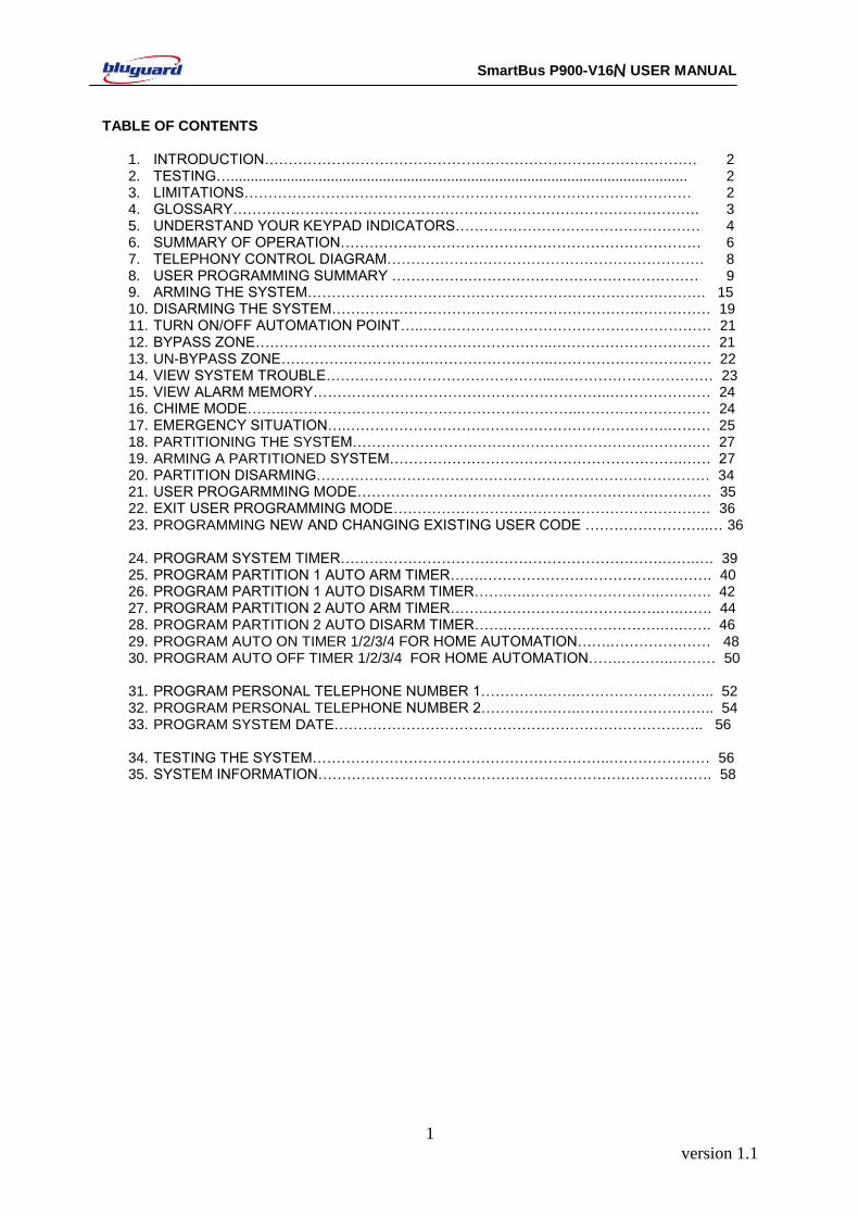
version 1.1 1 SmartBus P900-V16N USER MANUAL TABLE OF CONTENTS 1. INTRODUCTION……………………………………………………………………………… 2 2. TESTING….................................................................................................................. 2 3. LIMITATIONS………………………………………………………………………………… 2 4. GLOSSARY……………………………………………………………………………………. 3 5. UNDERSTAND YOUR KEYPAD INDICATORS…………………………………………… 4 6. SUMMARY OF OPERATION………………………………………………………………… 6 7. TELEPHONY CONTROL DIAGRAM………………………………………………………… 8 8. USER PROGRAMMING SUMMARY …………….………………………………………… 9 9. ARMING THE SYSTEM……………………………………………………………….………. 15 10. DISARMING THE SYSTEM……………………………………………………….…………… 19 11. TURN ON/OFF AUTOMATION POINT…..…………………………………………………… 21 12. BYPASS ZONE……………………………………………………..…………………………… 21 13. UN-BYPASS ZONE………………………….……………………..…………………………… 22 14. VIEW SYSTEM TROUBLE………………………………………...…………………………… 23 15. VIEW ALARM MEMORY……………………………………………………..………………… 24 16. CHIME MODE……..……………………………………………………..……………………… 24 17. EMERGENCY SITUATION….………………………………………………………….……… 25 18. PARTITIONING THE SYSTEM……………………………………………………..……….… 27 19. ARMING A PARTITIONED SYSTEM…………………………………………………….…… 27 20. PARTITION DISARMING…………….………………………………………………………… 34 21. USER PROGARMMING MODE……………………………………………………..………… 35 22. EXIT USER PROGRAMMING MODE………………………………………………………… 36 23. PROGRAMMING NEW AND CHANGING EXISTING USER CODE ……………………..… 36 24. PROGRAM SYSTEM TIMER………………………………………………………….…….…. 39 25. PROGRAM PARTITION 1 AUTO ARM TIMER…….……………………………….….……. 40 26. PROGRAM PARTITION 1 AUTO DISARM TIMER…….….……………………….….……. 42 27. PROGRAM PARTITION 2 AUTO ARM TIMER…….……………………………….….……. 44 28. PROGRAM PARTITION 2 AUTO DISARM TIMER…….….……………………….….……. 46 29. PROGRAM AUTO ON TIMER 1/2/3/4 FOR HOME AUTOMATION…….………………… 48 30. PROGRAM AUTO OFF TIMER 1/2/3/4 FOR HOME AUTOMATION…….………..……… 50 31. PROGRAM PERSONAL TELEPHONE NUMBER 1………….…….……………………….. 52 32. PROGRAM PERSONAL TELEPHONE NUMBER 2………….…….……………………….. 54 33. PROGRAM SYSTEM DATE………………………………………………………………….. 56 34. TESTING THE SYSTEM……………………………………………………..………………… 56 35. SYSTEM INFORMATION………………………………………………………………………. 58
Transcript of SmartBus P900-V16N USER MANUAL TABLE OF …...version 1.1 3 SmartBus P900-V16N USER MANUAL Alarm...
version 1.1
1
SmartBus P900-V16N USER MANUAL
TABLE OF CONTENTS
1. INTRODUCTION……………………………………………………………………………… 2 2. TESTING….................................................................................................................. 2 3. LIMITATIONS………………………………………………………………………………… 2 4. GLOSSARY……………………………………………………………………………………. 3 5. UNDERSTAND YOUR KEYPAD INDICATORS…………………………………………… 4 6. SUMMARY OF OPERATION………………………………………………………………… 6 7. TELEPHONY CONTROL DIAGRAM………………………………………………………… 8 8. USER PROGRAMMING SUMMARY …………….………………………………………… 9 9. ARMING THE SYSTEM……………………………………………………………….………. 15 10. DISARMING THE SYSTEM……………………………………………………….…………… 19 11. TURN ON/OFF AUTOMATION POINT…..…………………………………………………… 21 12. BYPASS ZONE……………………………………………………..…………………………… 21 13. UN-BYPASS ZONE………………………….……………………..…………………………… 22 14. VIEW SYSTEM TROUBLE………………………………………...…………………………… 23 15. VIEW ALARM MEMORY……………………………………………………..………………… 24 16. CHIME MODE……..……………………………………………………..……………………… 24 17. EMERGENCY SITUATION….………………………………………………………….……… 25 18. PARTITIONING THE SYSTEM……………………………………………………..……….… 27 19. ARMING A PARTITIONED SYSTEM…………………………………………………….…… 27 20. PARTITION DISARMING…………….………………………………………………………… 34 21. USER PROGARMMING MODE……………………………………………………..………… 35 22. EXIT USER PROGRAMMING MODE………………………………………………………… 36 23. PROGRAMMING NEW AND CHANGING EXISTING USER CODE ……………………..… 36
24. PROGRAM SYSTEM TIMER………………………………………………………….…….…. 39 25. PROGRAM PARTITION 1 AUTO ARM TIMER…….……………………………….….……. 40 26. PROGRAM PARTITION 1 AUTO DISARM TIMER…….….……………………….….……. 42 27. PROGRAM PARTITION 2 AUTO ARM TIMER…….……………………………….….……. 44 28. PROGRAM PARTITION 2 AUTO DISARM TIMER…….….……………………….….……. 46 29. PROGRAM AUTO ON TIMER 1/2/3/4 FOR HOME AUTOMATION…….………………… 48 30. PROGRAM AUTO OFF TIMER 1/2/3/4 FOR HOME AUTOMATION…….………..……… 50
31. PROGRAM PERSONAL TELEPHONE NUMBER 1………….…….……………………….. 52 32. PROGRAM PERSONAL TELEPHONE NUMBER 2………….…….……………………….. 54 33. PROGRAM SYSTEM DATE………………………………………………………………….. 56
34. TESTING THE SYSTEM……………………………………………………..………………… 56 35. SYSTEM INFORMATION………………………………………………………………………. 58
version 1.1
2
SmartBus P900-V16N USER MANUAL
The BLUGUARD Control Panel is designed for simple operation yet provides the maximum protection for you. Please read this manual carefully and follow the instructions contained in this book. Fill in the system information page and store this manual in a safe place for future reference. Your security system consists of a main control panel, one or more keypads and home automation (HA) modules, various sensors and detectors. An enclosure will contain the control panel, which includes the system electronics and standby battery. To ensure that your system is functioning, it is important that you test your system weekly. Please refer to testing procedures section in this manual. If your system does not function properly, please contact your system installer for services. There is normally no reason for anyone other than the installer or service professional to have access to the control panel. Even though BLUGUARD is an advanced security system, it does not 100% guarantee the protection against burglary, fire or other loses. Any alarm system whether commercial or residential is subjected to compromise or failure-to-warn for a variety of reasons. These include:
Intruders may gain access through unprotected openings or have the technical sophistication to bypass an alarm sensor or disconnect an alarm warning device.
Intrusion detectors, smoke detectors and many sensing devices will not operate without power. Devices powered by AC will not work if there is no AC power supply for any reason and the back-up battery is missing, dead or improperly installed.
Alarm warning devices such as sirens may not alert people or wake up sleepers if they are located on the other side of closed or partly closed doors.
Telephone line needed to transmit alarm events from the premise to a central monitoring station may be out or temporary out of service. Telephone line is subject to compromise by sophisticated method of attack.
Smoke detector used in conjunction with the alarm system may not sense fire that start from where smoke cannot reach the detector such as wall, roof or the other side of the doors. Smoke detector also may not sense a fire on another level of the residence or building. In general, detectors may not always warn you about fire caused by carelessness and safety hazards like smoking, violent explosions, escaping gas, improper storage of flammable material, overloaded electrical circuits, children playing with matches.
The most common cause of an alarm system not functioning properly when an intrusion or fire occurs is inadequate maintenance. Therefore, your system should be tested weekly to ensure all detectors or sensors are working properly.
Installing an alarm system may make you eligible for lower insurance rates but an alarm system is not a substitute for insurance. Homeowners, property owners and renters should continue to insure their lives and properties.
SYSTEM INFORMATION
Central Monitoring Station Number : ________________________________
Central Monitoring Station Account Number : ________________________________
Note: All information is subject to changes without prior notice.
INTRODUCTION
TESTING
LIMITATIONS
version 1.1
3
SmartBus P900-V16N USER MANUAL
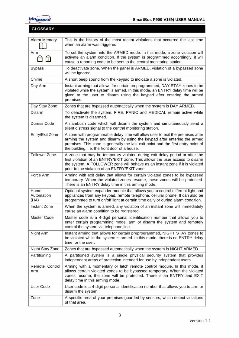
Alarm Memory
This is the history of the most recent violations that occurred the last time when an alarm was triggered.
Arm
To set the system into the ARMED mode. In this mode, a zone violation will activate an alarm condition. If the system is programmed accordingly, it will cause a reporting code to be sent to the central monitoring station.
Bypass
To deactivate zone. When the panel is ARMED, violation of a bypassed zone will be ignored.
Chime A short beep sound from the keypad to indicate a zone is violated.
Day Arm Instant arming that allows for certain preprogrammed, DAY STAY zones to be violated while the system is armed. In this mode, an ENTRY delay time will be given to the user to disarm using the keypad after entering the armed premises.
Day Stay Zone Zones that are bypassed automatically when the system is DAY ARMED.
Disarm
To deactivate the system. FIRE, PANIC and MEDICAL remain active while the system is disarmed.
Duress Code An ambush code which will disarm the system and simultaneously send a silent distress signal to the central monitoring station.
Entry/Exit Zone A zone with programmable delay time will allow user to exit the premises after arming the system and disarm by using the keypad after entering the armed premises. This zone is generally the last exit point and the first entry point of the building, i.e. the front door of a house.
Follower Zone A zone that may be temporary violated during exit delay period or after the first violation of an ENTRY/EXIT zone. This allows the user access to disarm the system. A FOLLOWER zone will behave as an instant zone if it is violated prior to the violation of an ENTRY/EXIT zone.
Force Arm Arming with exit delay that allows for certain violated zones to be bypassed temporary. When the violated zones resume, these zones will be protected. There is an ENTRY delay time in this arming mode.
Home Automation (HA)
Optional system expander module that allows you to control different light and appliances from any keypad, remote telephone, cellular phone. It can also be programmed to turn on/off light at certain time daily or during alarm condition.
Instant Zone When the system is armed, any violation of an instant zone will immediately cause an alarm condition to be registered.
Master Code Master code is a 4-digit personal identification number that allows you to enter certain programming mode, arm or disarm the system and remotely control the system via telephone line.
Night Arm Instant arming that allows for certain preprogrammed, NIGHT STAY zones to be violated while the system is armed. In this mode, there is no ENTRY delay time for the user.
Night Stay Zone Zones that are bypassed automatically when the system is NIGHT ARMED.
Partitioning A partitioned system is a single physical security system that provides independent areas of protection intended for use by independent users.
Remote Control Arm
Arming with a momentary or latch remote control module. In this mode, it allows certain violated zones to be bypassed temporary. When the violated zones resume, the zone will be protected. There is an ENTRY and EXIT delay time in this arming mode.
User Code User code is a 4-digit personal identification number that allows you to arm or disarm the system.
Zone A specific area of your premises guarded by sensors, which detect violations of that area.
GLOSSARY
version 1.1
4
SmartBus P900-V16N USER MANUAL
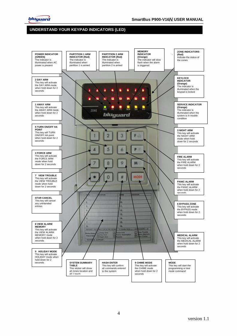
UNDERSTAND YOUR KEYPAD INDICATORS (LED)
ZONE INDICATORS (Red) Indicate the status of
the zones
POWER INDICATOR (GREEN)
The indicator is illuminated when AC
power is present
7 VIEW TROUBLE
This key will activate the VIEW TROUBLE mode when hold down for 2 seconds
8 VIEW ALARM MEMORY
This key will activate the VIEW ALARM MEMORY mode when hold down for 2 seconds
5 TURN ON/OFF HA POINT
This key will TURN ON/OFF HA point when hold down for 2
seconds
MODE
This key will start the programming or test
mode command
9 CHIME MODE
This key will activate the CHIME mode when hold down for 2 seconds
KEYLOCK INDICATOR (Orange) The indicator is illuminated when the keypad is locked
MEMORY INDICATOR (Orange)
The indicator will slow flash when the alarm
is triggered
1 AWAY ARM
This key will activate the AWAY ARM mode when hold down for 2 seconds
2 DAY ARM This key will activate the DAY ARM mode when hold down for 2
seconds
4 FORCE ARM This key will activate the FORCE ARM mode when hold
down for 2 seconds
3 NIGHT ARM
This key will activate the NIGHT ARM mode when hold down for 2 seconds
FIRE ALARM This key will activate the FIRE ALARM when hold down for 2 seconds
6 BYPASS ZONE This key will activate the BYPASS mode when hold down for 2
seconds
PANIC ALARM This key will activate the PANIC ALARM when hold down for 2 seconds
MEDICAL ALARM This key will activate the MEDICAL ALARM when hold down for 2
seconds
SERVICE INDICATOR (Orange) The indicator is illuminated when the system is in trouble
condition
HASH ENTER
This key will confirm all commands entered
to the system
0 HOLIDAY MODE This key will activate HOLIDAY mode when hold down for 2 seconds
STAR CANCEL This key will cancel any unintended entries
SYSTEM SUMMARY TABLE This sticker will show all zones location and all 1 touch
PARTITION 1 ARM INDICATOR (Red)
The indicator is illuminated when partition 1 is armed
PARTITION 2 ARM INDICATOR (Red)
The indicator is illuminated when partition 2 is armed
version 1.1
5
SmartBus P900-V16N USER MANUAL
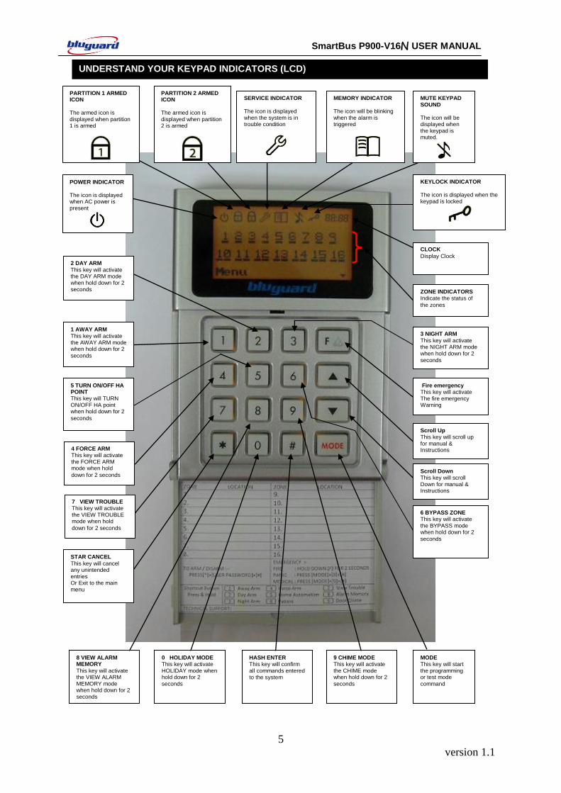
UNDERSTAND YOUR KEYPAD INDICATORS (LCD)
ZONE INDICATORS Indicate the status of
the zones
POWER INDICATOR
The icon is displayed when AC power is present
7 VIEW TROUBLE This key will activate the VIEW TROUBLE mode when hold
down for 2 seconds
8 VIEW ALARM MEMORY
This key will activate the VIEW ALARM MEMORY mode when hold down for 2 seconds
5 TURN ON/OFF HA POINT This key will TURN ON/OFF HA point when hold down for 2
seconds
0 HOLIDAY MODE This key will activate HOLIDAY mode when hold down for 2
seconds
MODE This key will start the programming or test mode
command
9 CHIME MODE This key will activate the CHIME mode when hold down for 2
seconds
HASH ENTER This key will confirm all commands entered to the system
KEYLOCK INDICATOR The icon is displayed when the keypad is locked
MEMORY INDICATOR The icon will be blinking when the alarm is triggered
1 AWAY ARM This key will activate the AWAY ARM mode when hold down for 2
seconds
2 DAY ARM
This key will activate the DAY ARM mode when hold down for 2 seconds
4 FORCE ARM This key will activate the FORCE ARM mode when hold
down for 2 seconds
3 NIGHT ARM
This key will activate the NIGHT ARM mode when hold down for 2
seconds
Fire emergency This key will activate The fire emergency Warning
6 BYPASS ZONE This key will activate the BYPASS mode when hold down for 2
seconds
Scroll Up This key will scroll up for manual & Instructions
SERVICE INDICATOR The icon is displayed when the system is in trouble condition
MUTE KEYPAD SOUND
The icon will be displayed when the keypad is muted.
Scroll Down This key will scroll Down for manual & Instructions
CLOCK
Display Clock
PARTITION 2 ARMED ICON
The armed icon is displayed when partition 2 is armed
PARTITION 1 ARMED ICON
The armed icon is displayed when partition 1 is armed
STAR CANCEL
This key will cancel any unintended entries Or Exit to the main menu

version 1.1
6
SmartBus P900-V16N USER MANUAL
Intelligent Disarm [4-digit User Code] + [#]
Intelligent Arming [4-digit User Code] + [#]
Away Arm Hold down [1] for 2 seconds
Day Arm Hold down [2] for 2 seconds
Night Arm Hold down [3] for 2 seconds
Force Arm Hold down [4] for 2 seconds
Turn On/Off Home Automation Point
Hold down [5] for 2 seconds + [HA point numbers 1 to 8] + [#]
Bypass Security Zone Hold down [6] for 2 seconds + [zone numbers 1 to 16] + [#]
View System Trouble Hold down [7] for 2 seconds
View Alarm Memory Hold down [8] for 2 seconds
Program Chime Zone Hold down [9] for 2 seconds + [zone numbers 1 to 16] + [#]
Holiday Mode Arming Hold down [0] for 2 seconds
Activate Fire Alarm Hold down [F] for 2 seconds
Activate Panic Alarm LED: Hold down [P] for 2 seconds LCD: Press [MODE] + [8] + [#]
Activate Medical Alarm LED: Hold down [M] for 2 seconds LCD: Press [MODE] + [9] + [#]
Turn On/Off Keypad Buzzer
LED: Hold down [MODE] for 2 seconds LCD: Press [MODE] + [6] + [#]
Remark: To enter zone number more than 9, press button [F] to represent the ten’s digit. e.g. To enter zone number 15, press [F] + [5].
SUMMARY OF OPERATION
version 1.1
7
SmartBus P900-V16N USER MANUAL
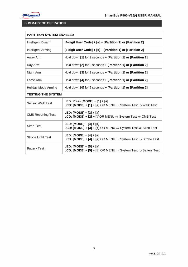
PARTITION SYSTEM ENABLED
Intelligent Disarm [4-digit User Code] + [#] + [Partition 1] or [Partition 2]
Intelligent Arming [4-digit User Code] + [#] + [Partition 1] or [Partition 2]
Away Arm Hold down [1] for 2 seconds + [Partition 1] or [Partition 2]
Day Arm Hold down [2] for 2 seconds + [Partition 1] or [Partition 2]
Night Arm Hold down [3] for 2 seconds + [Partition 1] or [Partition 2]
Force Arm Hold down [4] for 2 seconds + [Partition 1] or [Partition 2]
Holiday Mode Arming Hold down [0] for 2 seconds + [Partition 1] or [Partition 2]
TESTING THE SYSTEM
Sensor Walk Test LED: Press [MODE] + [1] + [#]
LCD: [MODE] + [1] + [#] OR MENU System Test Walk Test
CMS Reporting Test LED: [MODE] + [2] + [#]
LCD: [MODE] + [2] + [#]OR MENU System Test CMS Test
Siren Test LED: [MODE] + [3] + [#]
LCD: [MODE] + [3] + [#] OR MENU System Test Siren Test
Strobe Light Test LED: [MODE] + [4] + [#]
LCD: [MODE] + [4] + [#] OR MENU System Test Strobe Test
Battery Test LED: [MODE] + [5] + [#]
LCD: [MODE] + [5] + [#] OR MENU System Test Battery Test
SUMMARY OF OPERATION
version 1.1
8
SmartBus P900-V16N USER MANUAL
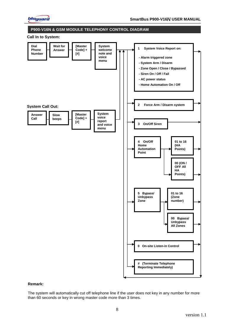
Remark: The system will automatically cut off telephone line if the user does not key in any number for more than 60 seconds or key in wrong master code more than 3 times.
P900-V16N & GSM MODULE TELEPHONY CONTROL DIAGRAM
Call In to System:
# (Terminate Telephone
Reporting Immediately)
2 Force Arm / Disarm system
1 System Voice Report on:
- Alarm triggered zone
- System Arm / Disarm
- Zone Open / Close / Bypassed
- Siren On / Off / Fail
- AC power status
- Home Automation On / Off
4 On/Off Home Automation Point
01 to 16 (HA
Points)
00 (ON / OFF All HA
Points)
Dial Phone
Number
Wait for
Answer
System Call Out:
System welcome note and voice menu
3 On/Off Siren
01 to 16 (Zone
number)
Answer
Call
5 Bypass/ Unbypass
Zone
[Master Code] +
[#]
Slow
beeps
[Master Code] +
[#]
00 Bypass/ Unbypass
All Zones
System voice report and voice menu
0 On-site Listen-in Control
version 1.1
9
SmartBus P900-V16N USER MANUAL
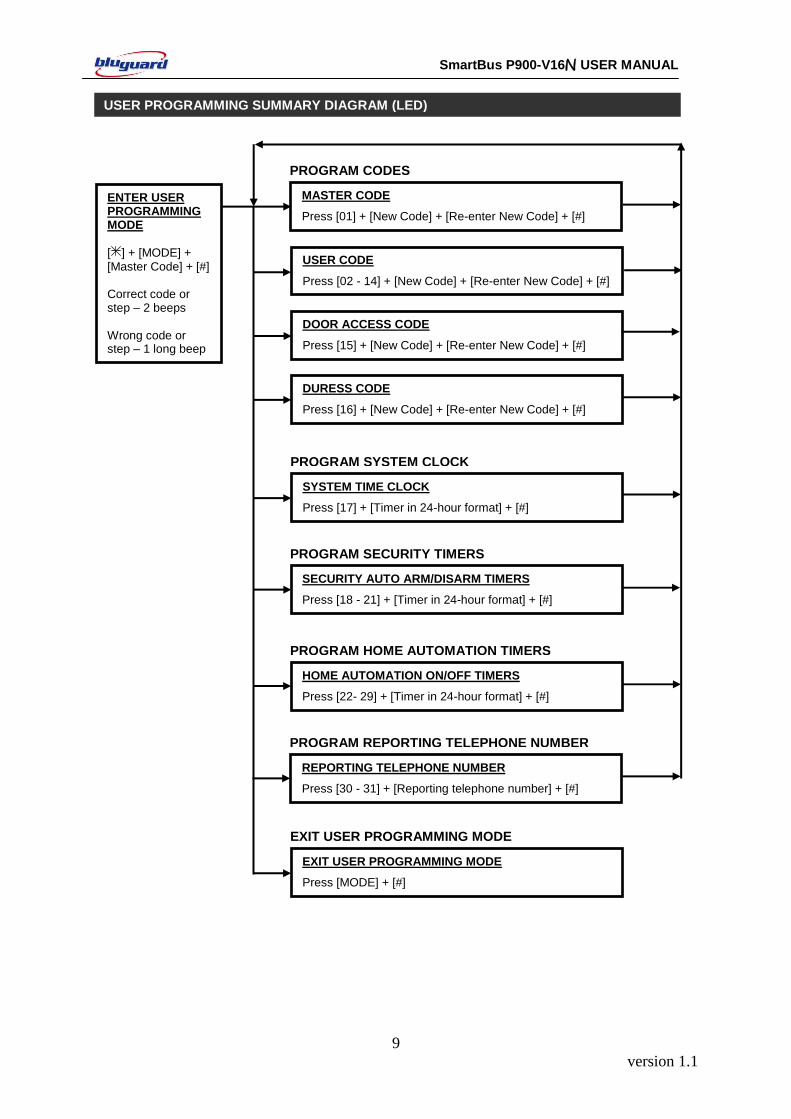
USER PROGRAMMING SUMMARY DIAGRAM (LED) The indicator is illuminated when the keypad is locked
ER PROGRAMMING SUMMARY TABLE
ENTER USER PROGRAMMING MODE
[ ] + [MODE] + [Master Code] + [#] Correct code or step – 2 beeps Wrong code or step – 1 long beep
MASTER CODE
Press [01] + [New Code] + [Re-enter New Code] + [#]
PROGRAM CODES
USER CODE
Press [02 - 14] + [New Code] + [Re-enter New Code] + [#]
DOOR ACCESS CODE
Press [15] + [New Code] + [Re-enter New Code] + [#]
DURESS CODE
Press [16] + [New Code] + [Re-enter New Code] + [#]
SYSTEM TIME CLOCK
Press [17] + [Timer in 24-hour format] + [#]
PROGRAM SYSTEM CLOCK
SECURITY AUTO ARM/DISARM TIMERS
Press [18 - 21] + [Timer in 24-hour format] + [#]
PROGRAM SECURITY TIMERS
HOME AUTOMATION ON/OFF TIMERS
Press [22- 29] + [Timer in 24-hour format] + [#]
PROGRAM HOME AUTOMATION TIMERS
REPORTING TELEPHONE NUMBER
Press [30 - 31] + [Reporting telephone number] + [#]
PROGRAM REPORTING TELEPHONE NUMBER
EXIT USER PROGRAMMING MODE
Press [MODE] + [#]
EXIT USER PROGRAMMING MODE
version 1.1
10
SmartBus P900-V16N USER MANUAL
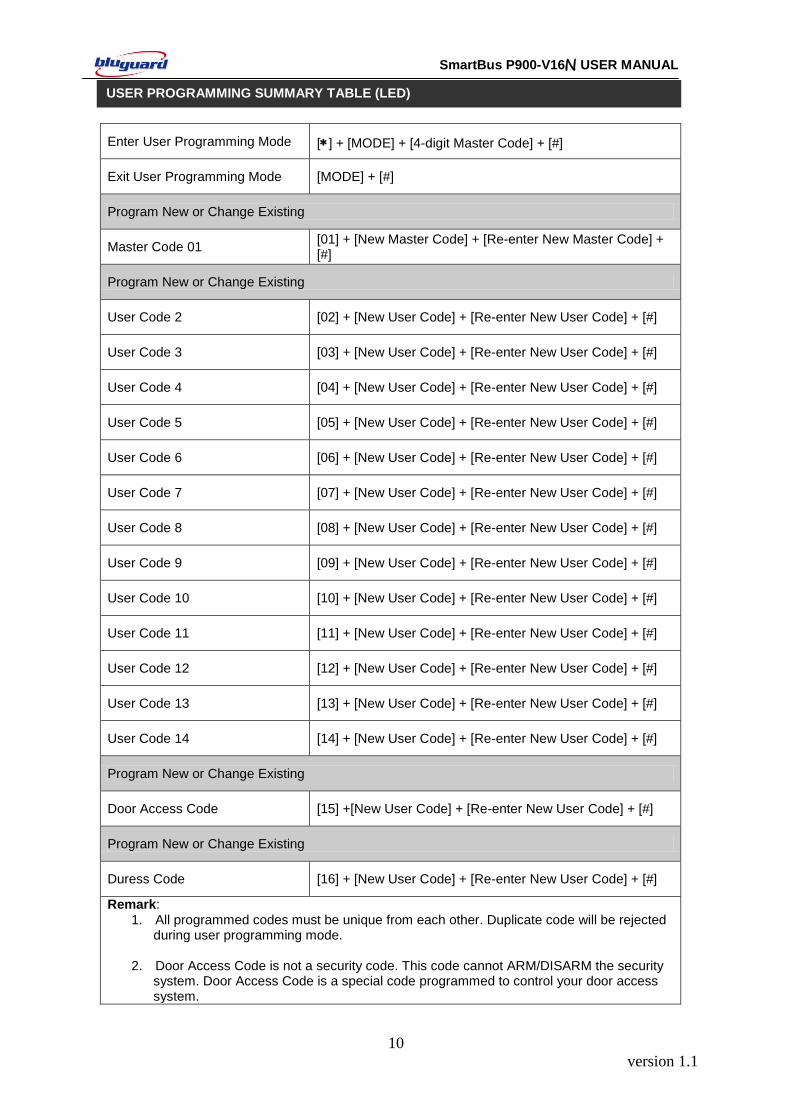
Enter User Programming Mode [] + [MODE] + [4-digit Master Code] + [#]
Exit User Programming Mode [MODE] + [#]
Program New or Change Existing
Master Code 01 [01] + [New Master Code] + [Re-enter New Master Code] + [#]
Program New or Change Existing
User Code 2 [02] + [New User Code] + [Re-enter New User Code] + [#]
User Code 3 [03] + [New User Code] + [Re-enter New User Code] + [#]
User Code 4 [04] + [New User Code] + [Re-enter New User Code] + [#]
User Code 5 [05] + [New User Code] + [Re-enter New User Code] + [#]
User Code 6 [06] + [New User Code] + [Re-enter New User Code] + [#]
User Code 7 [07] + [New User Code] + [Re-enter New User Code] + [#]
User Code 8 [08] + [New User Code] + [Re-enter New User Code] + [#]
User Code 9 [09] + [New User Code] + [Re-enter New User Code] + [#]
User Code 10 [10] + [New User Code] + [Re-enter New User Code] + [#]
User Code 11 [11] + [New User Code] + [Re-enter New User Code] + [#]
User Code 12 [12] + [New User Code] + [Re-enter New User Code] + [#]
User Code 13 [13] + [New User Code] + [Re-enter New User Code] + [#]
User Code 14 [14] + [New User Code] + [Re-enter New User Code] + [#]
Program New or Change Existing
Door Access Code [15] +[New User Code] + [Re-enter New User Code] + [#]
Program New or Change Existing
Duress Code [16] + [New User Code] + [Re-enter New User Code] + [#]
Remark: 1. All programmed codes must be unique from each other. Duplicate code will be rejected during user programming mode. 2. Door Access Code is not a security code. This code cannot ARM/DISARM the security system. Door Access Code is a special code programmed to control your door access system.
USER PROGRAMMING SUMMARY TABLE (LED)
version 1.1
11
SmartBus P900-V16N USER MANUAL
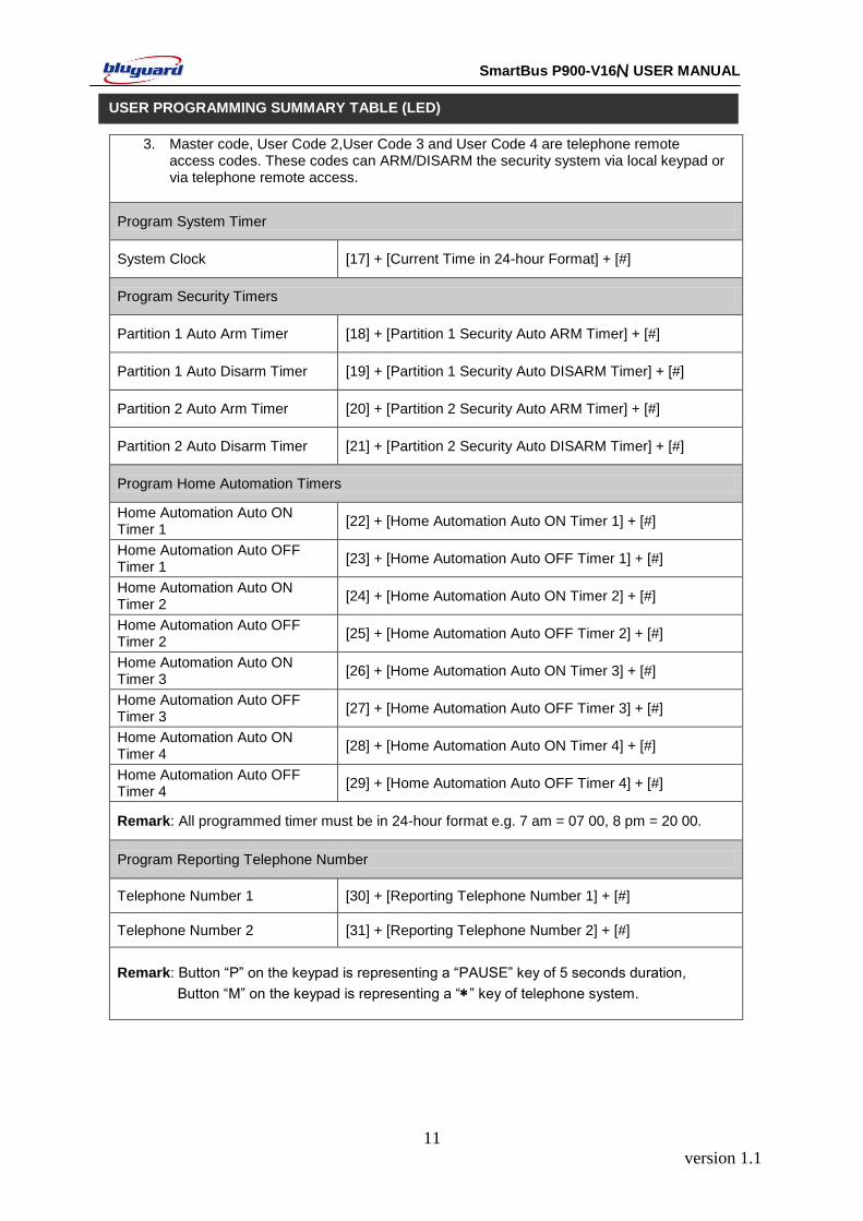
3. Master code, User Code 2,User Code 3 and User Code 4 are telephone remote access codes. These codes can ARM/DISARM the security system via local keypad or via telephone remote access.
Program System Timer
System Clock [17] + [Current Time in 24-hour Format] + [#]
Program Security Timers
Partition 1 Auto Arm Timer [18] + [Partition 1 Security Auto ARM Timer] + [#]
Partition 1 Auto Disarm Timer [19] + [Partition 1 Security Auto DISARM Timer] + [#]
Partition 2 Auto Arm Timer [20] + [Partition 2 Security Auto ARM Timer] + [#]
Partition 2 Auto Disarm Timer [21] + [Partition 2 Security Auto DISARM Timer] + [#]
Program Home Automation Timers
Home Automation Auto ON Timer 1
[22] + [Home Automation Auto ON Timer 1] + [#]
Home Automation Auto OFF Timer 1
[23] + [Home Automation Auto OFF Timer 1] + [#]
Home Automation Auto ON Timer 2
[24] + [Home Automation Auto ON Timer 2] + [#]
Home Automation Auto OFF Timer 2
[25] + [Home Automation Auto OFF Timer 2] + [#]
Home Automation Auto ON Timer 3
[26] + [Home Automation Auto ON Timer 3] + [#]
Home Automation Auto OFF Timer 3
[27] + [Home Automation Auto OFF Timer 3] + [#]
Home Automation Auto ON Timer 4
[28] + [Home Automation Auto ON Timer 4] + [#]
Home Automation Auto OFF Timer 4
[29] + [Home Automation Auto OFF Timer 4] + [#]
Remark: All programmed timer must be in 24-hour format e.g. 7 am = 07 00, 8 pm = 20 00.
Program Reporting Telephone Number
Telephone Number 1 [30] + [Reporting Telephone Number 1] + [#]
Telephone Number 2 [31] + [Reporting Telephone Number 2] + [#]
Remark: Button “P” on the keypad is representing a “PAUSE” key of 5 seconds duration,
Button “M” on the keypad is representing a “” key of telephone system.
USER PROGRAMMING SUMMARY TABLE (LED)
version 1.1
12
SmartBus P900-V16N USER MANUAL
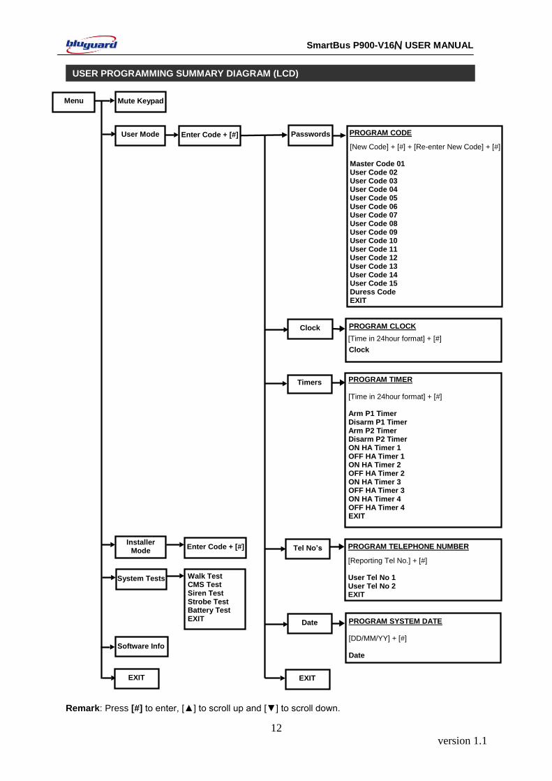
Remark: Press [#] to enter, [▲] to scroll up and [▼] to scroll down.
USER PROGRAMMING SUMMARY DIAGRAM (LCD) The indicator is illuminated when the keypad is locked
ER PROGRAMMING SUMMARY TABLE Menu Mute Keypad
PROGRAM TIMER
PROGRAM CODE
[New Code] + [#] + [Re-enter New Code] + [#] Master Code 01 User Code 02 User Code 03 User Code 04 User Code 05 User Code 06 User Code 07 User Code 08 User Code 09 User Code 10 User Code 11 User Code 12 User Code 13 User Code 14 User Code 15 Duress Code EXIT
PROGRAM TIMER [Time in 24hour format] + [#] Arm P1 Timer Disarm P1 Timer Arm P2 Timer Disarm P2 Timer ON HA Timer 1 OFF HA Timer 1 ON HA Timer 2 OFF HA Timer 2 ON HA Timer 3 OFF HA Timer 3 ON HA Timer 4 OFF HA Timer 4 EXIT
PROGRAM CLOCK [Time in 24hour format] + [#]
Clock
PROGRAM TELEPHONE NUMBER
[Reporting Tel No.] + [#] User Tel No 1 User Tel No 2 EXIT
Passwords
Clock
Timers
Tel No’s
EXIT
Enter Code + [#] User Mode
System Tests
Installer Mode Enter Code + [#]
Walk Test CMS Test Siren Test Strobe Test Battery Test EXIT
EXIT
Software Info
PROGRAM SYSTEM DATE [DD/MM/YY] + [#] Date
Date
version 1.1
13
SmartBus P900-V16N USER MANUAL
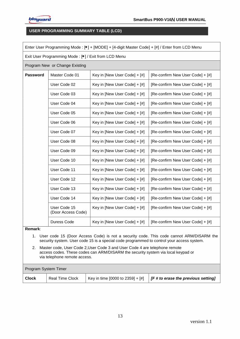
Enter User Programming Mode : [] + [MODE] + [4-digit Master Code] + [#] / Enter from LCD Menu
Exit User Programming Mode : [] / Exit from LCD Menu
Program New or Change Existing
Password Master Code 01 Key in [New User Code] + [#] [Re-confirm New User Code] + [#]
User Code 02 Key in [New User Code] + [#] [Re-confirm New User Code] + [#]
User Code 03 Key in [New User Code] + [#] [Re-confirm New User Code] + [#]
User Code 04 Key in [New User Code] + [#] [Re-confirm New User Code] + [#]
User Code 05 Key in [New User Code] + [#] [Re-confirm New User Code] + [#]
User Code 06 Key in [New User Code] + [#] [Re-confirm New User Code] + [#]
User Code 07 Key in [New User Code] + [#] [Re-confirm New User Code] + [#]
User Code 08 Key in [New User Code] + [#] [Re-confirm New User Code] + [#]
User Code 09 Key in [New User Code] + [#] [Re-confirm New User Code] + [#]
User Code 10 Key in [New User Code] + [#] [Re-confirm New User Code] + [#]
User Code 11 Key in [New User Code] + [#] [Re-confirm New User Code] + [#]
User Code 12 Key in [New User Code] + [#] [Re-confirm New User Code] + [#]
User Code 13 Key in [New User Code] + [#] [Re-confirm New User Code] + [#]
User Code 14 Key in [New User Code] + [#] [Re-confirm New User Code] + [#]
User Code 15 (Door Access Code)
Key in [New User Code] + [#] [Re-confirm New User Code] + [#]
Duress Code Key in [New User Code] + [#] [Re-confirm New User Code] + [#]
Remark:
1. User code 15 (Door Access Code) is not a security code. This code cannot ARM/DISARM the security system. User code 15 is a special code programmed to control your access system.
2. Master code, User Code 2,User Code 3 and User Code 4 are telephone remote access codes. These codes can ARM/DISARM the security system via local keypad or via telephone remote access.
Program System Timer
Clock Real Time Clock Key in time [0000 to 2359] + [#] [F # to erase the previous setting]
USER PROGRAMMING SUMMARY TABLE (LCD)
version 1.1
14
SmartBus P900-V16N USER MANUAL
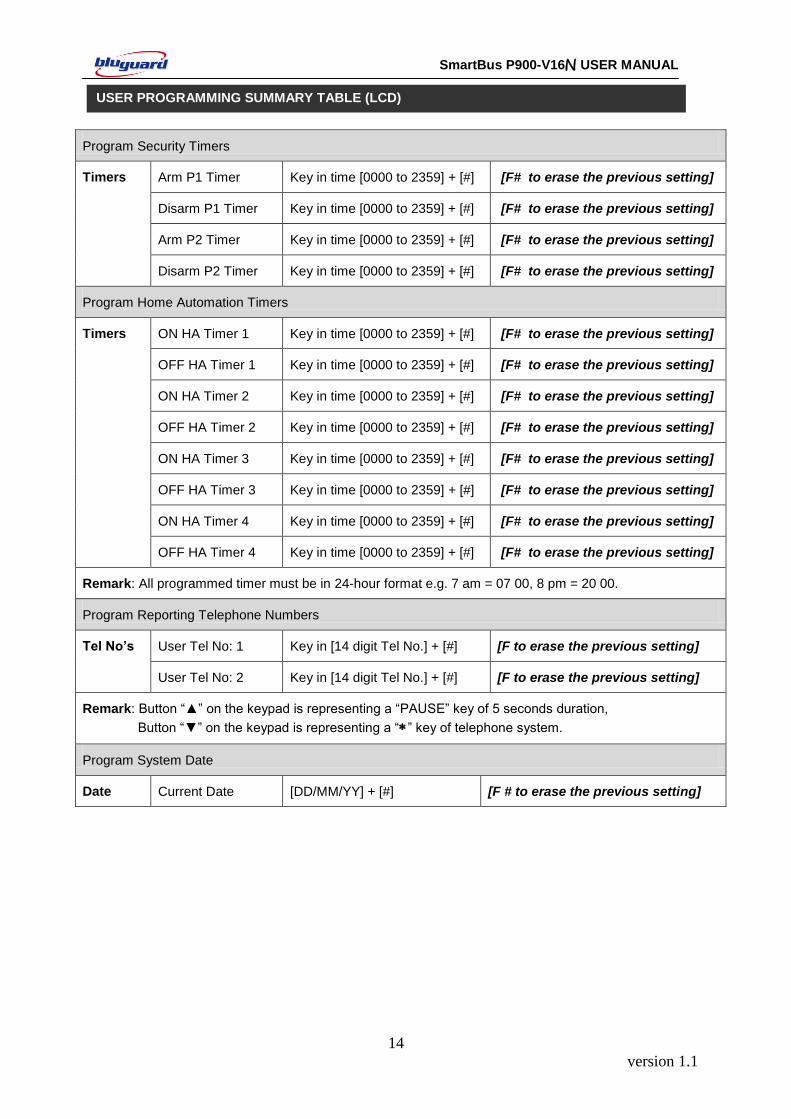
Program Security Timers
Timers Arm P1 Timer Key in time [0000 to 2359] + [#] [F# to erase the previous setting]
Disarm P1 Timer Key in time [0000 to 2359] + [#] [F# to erase the previous setting]
Arm P2 Timer Key in time [0000 to 2359] + [#] [F# to erase the previous setting]
Disarm P2 Timer Key in time [0000 to 2359] + [#] [F# to erase the previous setting]
Program Home Automation Timers
Timers ON HA Timer 1 Key in time [0000 to 2359] + [#] [F# to erase the previous setting]
OFF HA Timer 1 Key in time [0000 to 2359] + [#] [F# to erase the previous setting]
ON HA Timer 2 Key in time [0000 to 2359] + [#] [F# to erase the previous setting]
OFF HA Timer 2 Key in time [0000 to 2359] + [#] [F# to erase the previous setting]
ON HA Timer 3 Key in time [0000 to 2359] + [#] [F# to erase the previous setting]
OFF HA Timer 3 Key in time [0000 to 2359] + [#] [F# to erase the previous setting]
ON HA Timer 4 Key in time [0000 to 2359] + [#] [F# to erase the previous setting]
OFF HA Timer 4 Key in time [0000 to 2359] + [#] [F# to erase the previous setting]
Remark: All programmed timer must be in 24-hour format e.g. 7 am = 07 00, 8 pm = 20 00.
Program Reporting Telephone Numbers
Tel No’s User Tel No: 1 Key in [14 digit Tel No.] + [#] [F to erase the previous setting]
User Tel No: 2 Key in [14 digit Tel No.] + [#] [F to erase the previous setting]
Remark: Button “▲” on the keypad is representing a “PAUSE” key of 5 seconds duration,
Button “▼” on the keypad is representing a “” key of telephone system.
Program System Date
Date Current Date [DD/MM/YY] + [#] [F # to erase the previous setting]
USER PROGRAMMING SUMMARY TABLE (LCD)
version 1.1
15
SmartBus P900-V16N USER MANUAL
There are various options for arming the system
a. Partition Arming b. Away Arming c. Day Arming d. Night Arming e. Force Arming f. Holiday Arming g. Remote Control Arming h. Timer Auto Arming i. Telephone Remote Arming
For information on how to ARM Partition system, please refer to PARTITIONING THE SYSTEM at page 27.
[] + [USER CODE] + [#] (Leave via ENTRY/EXIT Zone)
1. Ensure that all zone indicators are distinguished; if not, check that all protected premises are closed.
2. Press the [] key to cancel any unintended entries.
3. Enter a valid 4-digit [USER CODE]. If you enter any mistakes, press [] key and re-enter the code followed by [#] key to confirm you command.
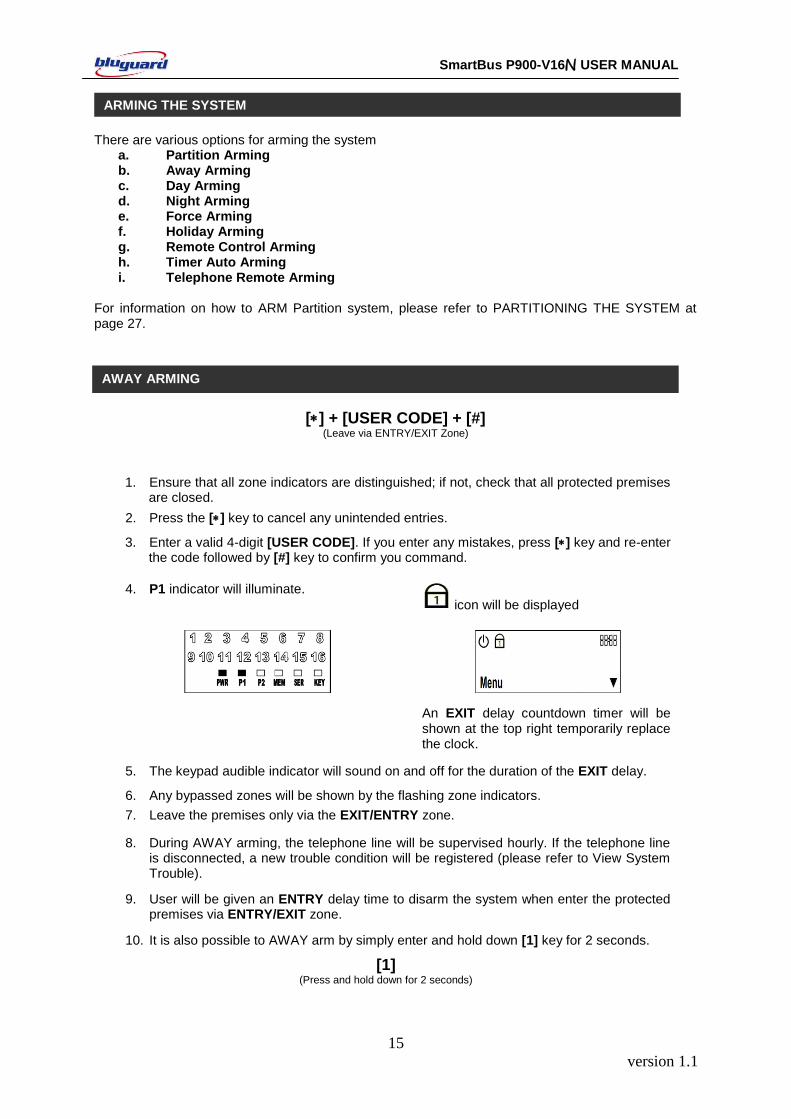
4. P1 indicator will illuminate.
icon will be displayed
An EXIT delay countdown timer will be shown at the top right temporarily replace the clock.
5. The keypad audible indicator will sound on and off for the duration of the EXIT delay.
6. Any bypassed zones will be shown by the flashing zone indicators.
7. Leave the premises only via the EXIT/ENTRY zone.
8. During AWAY arming, the telephone line will be supervised hourly. If the telephone line is disconnected, a new trouble condition will be registered (please refer to View System Trouble).
9. User will be given an ENTRY delay time to disarm the system when enter the protected premises via ENTRY/EXIT zone.
10. It is also possible to AWAY arm by simply enter and hold down [1] key for 2 seconds.
[1] (Press and hold down for 2 seconds)
ARMING THE SYSTEM
AWAY ARMING
version 1.1
16
SmartBus P900-V16N USER MANUAL
[2] (Press and hold down for 2 seconds)
1. This arming mode is ideal for DAY time arming with user still remains in the protected premises.
2. In this mode, the system will be armed instantly with certain preprogrammed, DAY STAY zones bypassed automatically.
3. Ensure that all zone indicators are distinguished; if not, check that all protected premises are closed.
4. DO NOT open the ENTRY/EXIT zone.
5. Enter and hold down [2] key for 2 seconds.
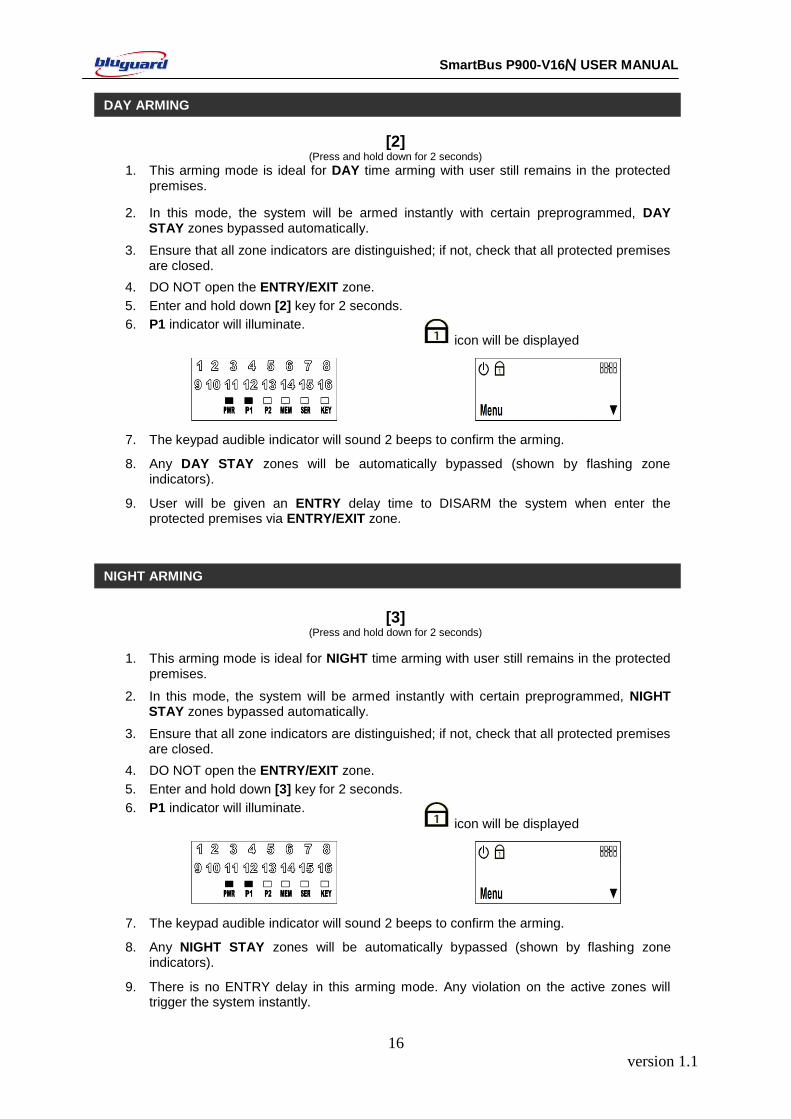
6. P1 indicator will illuminate.
icon will be displayed
7. The keypad audible indicator will sound 2 beeps to confirm the arming.
8. Any DAY STAY zones will be automatically bypassed (shown by flashing zone indicators).
9. User will be given an ENTRY delay time to DISARM the system when enter the protected premises via ENTRY/EXIT zone.
[3]
(Press and hold down for 2 seconds)
1. This arming mode is ideal for NIGHT time arming with user still remains in the protected premises.
2. In this mode, the system will be armed instantly with certain preprogrammed, NIGHT STAY zones bypassed automatically.
3. Ensure that all zone indicators are distinguished; if not, check that all protected premises are closed.
4. DO NOT open the ENTRY/EXIT zone.
5. Enter and hold down [3] key for 2 seconds.
6. P1 indicator will illuminate.
icon will be displayed
7. The keypad audible indicator will sound 2 beeps to confirm the arming.
8. Any NIGHT STAY zones will be automatically bypassed (shown by flashing zone indicators).
9. There is no ENTRY delay in this arming mode. Any violation on the active zones will trigger the system instantly.
DAY ARMING
NIGHT ARMING

version 1.1
17
SmartBus P900-V16N USER MANUAL
[4] (Press and hold down for 2 seconds)
1. In this mode, the system will be armed with EXIT delay time which allows certain
violated zones to be bypassed temporary. When the violated zones resume, the zone will be protected again.
2. Enter and hold down [4] key for 2 seconds.
3. P1 indicator will illuminate.
icon will be displayed
An EXIT delay countdown timer will be shown at the top right temporarily replace the clock.
4. The keypad audible indicator will sound on and off for the duration of the EXIT delay.
5. Any bypassed zones will be shown by the flashing zone indicators
6. User will be given an ENTRY delay time to DISARM the system when enter the protected premises via ENTRY/EXIT zone.
[0] (Press and hold down for 2 seconds)
1. This arming mode is ideal for long away occasion (holiday).
2. In this mode, the system will be AWAY armed. Home Automation points will be random ON/OFF every hour to simulate occupancy from 7pm to 1am.
3. Ensure that all zone indicators are distinguished; if not, check that all protected premises are closed.
4. Enter and hold down [0] key for 2 seconds.
5. P1 indicator will illuminate.
icon will be displayed
An EXIT delay countdown timer will be shown at the top right temporarily replace the clock.
6. The keypad audible indicator will sound on and off for the duration of the EXIT delay.
7. Any bypassed zones will be shown by the flashing zone indicators.
8. Leave the premises only via the EXIT/ENTRY zone.
9. User will be given an ENTRY delay time to disarm the system when enter the protected premises via ENTRY/EXIT zone.
FORCE ARMING
HOLIDAY ARMING
version 1.1
18
SmartBus P900-V16N USER MANUAL
10. After disarming, Home Automation random ON/OFF function will be deactivated and the system will resume to normal Home Automation ON/OFF timers setting.
1. This arming mode is ideal for remote control unit or key-switch arming.
2. The system will arm in AWAY arming mode.
3. The system will be armed with EXIT delay time which allows certain violated zones to be bypassed temporary. When the violated zones resume, the zone will be protected again.
4. Press the remote control button or twist and release the key-switch.
5. The system will be armed instantly. Leave the premises via ENTRY/EXIT zone.
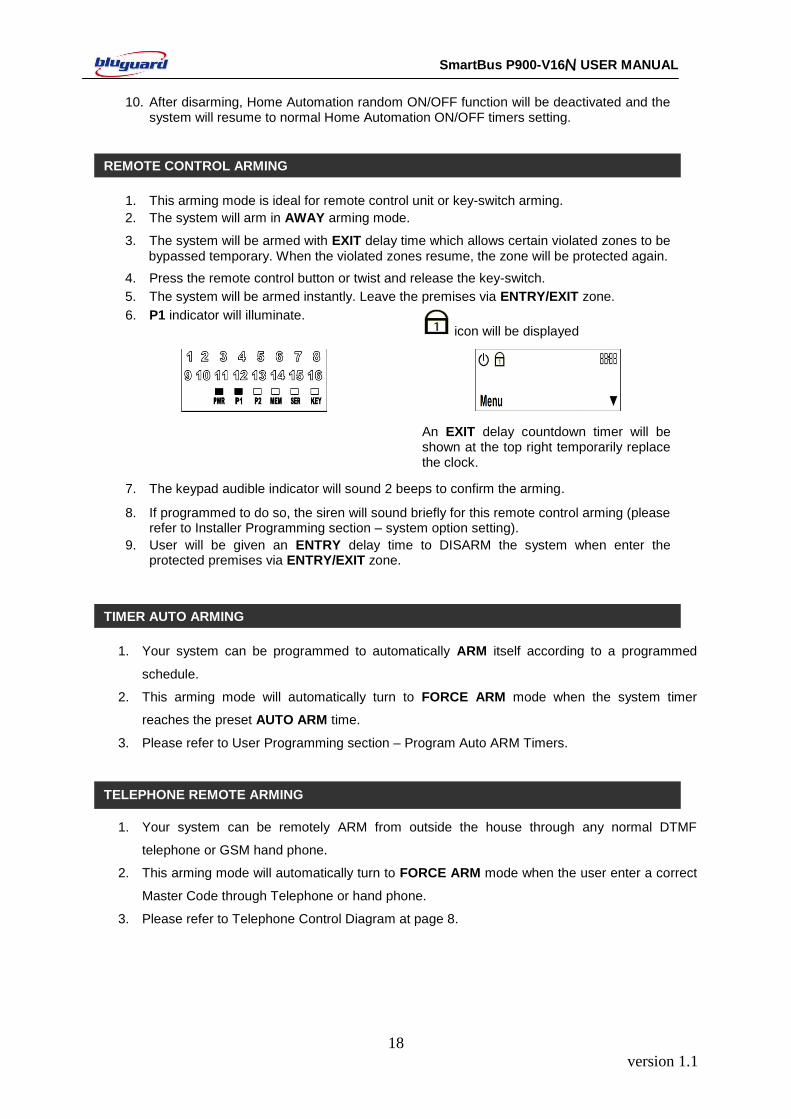
6. P1 indicator will illuminate.
icon will be displayed
An EXIT delay countdown timer will be shown at the top right temporarily replace the clock.
7. The keypad audible indicator will sound 2 beeps to confirm the arming.
8. If programmed to do so, the siren will sound briefly for this remote control arming (please refer to Installer Programming section – system option setting).
9. User will be given an ENTRY delay time to DISARM the system when enter the protected premises via ENTRY/EXIT zone.
1. Your system can be programmed to automatically ARM itself according to a programmed
schedule.
2. This arming mode will automatically turn to FORCE ARM mode when the system timer
reaches the preset AUTO ARM time.
3. Please refer to User Programming section – Program Auto ARM Timers.
1. Your system can be remotely ARM from outside the house through any normal DTMF
telephone or GSM hand phone.
2. This arming mode will automatically turn to FORCE ARM mode when the user enter a correct
Master Code through Telephone or hand phone.
3. Please refer to Telephone Control Diagram at page 8.
REMOTE CONTROL ARMING
TIMER AUTO ARMING
TELEPHONE REMOTE ARMING
version 1.1
19
SmartBus P900-V16N USER MANUAL
There are various options for disarming the system:
a. Partition Disarming
b. Keypad Disarming
c. Remote Control Disarming
d. Timer Auto Disarming
e. Telephone Remote Disarm
For information on how to DISARM Partition system, please refer to PARTITION DISARMING at
page 34.
[USER CODE] + [#]
1. To disarm the system, enter a valid 4-digit [USER CODE] followed by [#] key before expiry of the entry delay time.
2. Enter the premises through a designated ENTRY/EXIT zone; entering via other zones will trigger an alarm instantly.
3. The ENTRY delay begins once the ENTRY zone is violated.
4. The keypad audible indicator will sound for the duration of the ENTRY delay to indicate that a valid user code is required.
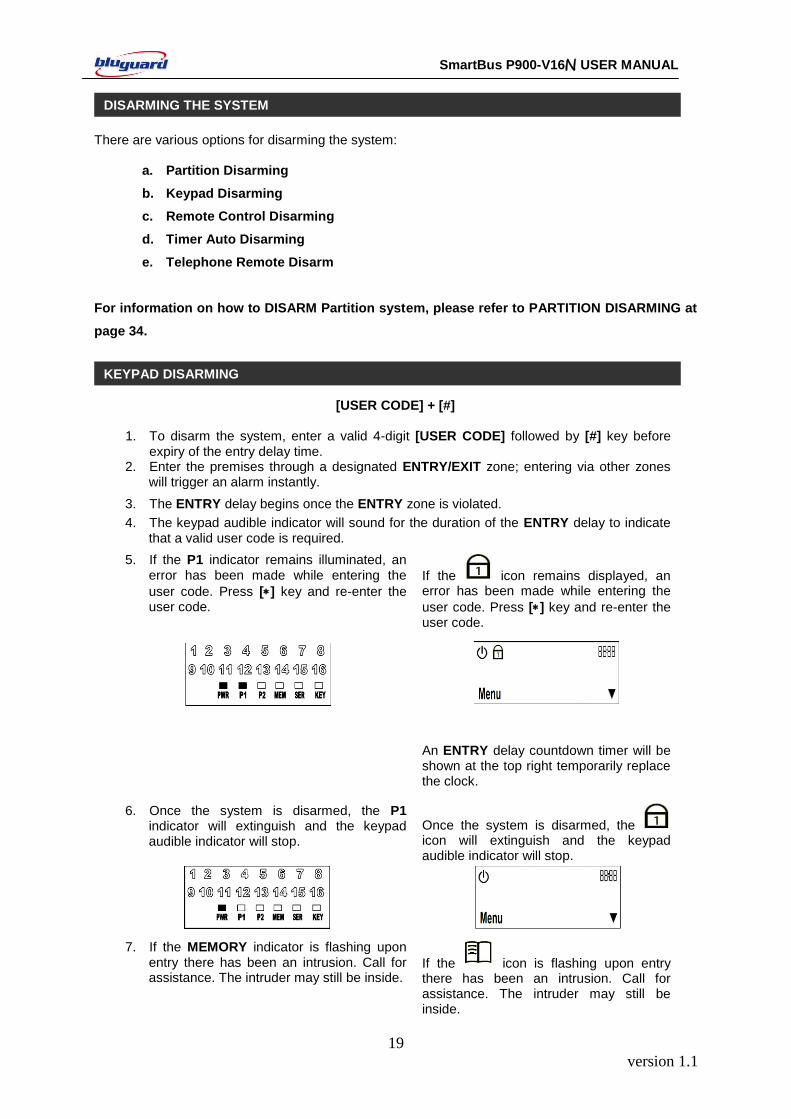
5. If the P1 indicator remains illuminated, an error has been made while entering the
user code. Press [] key and re-enter the user code.
If the icon remains displayed, an error has been made while entering the
user code. Press [] key and re-enter the user code.
An ENTRY delay countdown timer will be shown at the top right temporarily replace the clock.
6. Once the system is disarmed, the P1 indicator will extinguish and the keypad audible indicator will stop.
Once the system is disarmed, the icon will extinguish and the keypad audible indicator will stop.
7. If the MEMORY indicator is flashing upon entry there has been an intrusion. Call for assistance. The intruder may still be inside.
If the icon is flashing upon entry there has been an intrusion. Call for assistance. The intruder may still be inside.
KEYPAD DISARMING
DISARMING THE SYSTEM
version 1.1
20
SmartBus P900-V16N USER MANUAL
8. If no valid user code has been entered by the end of the ENTRY delay period, an ALARM condition will be registered and stored into the system MEMORY.
9. If programmed to do so, the keypad will be locked and non-responsive for a preprogrammed period for certain number of incorrect user codes, which are entered consecutively more than the keypad lock counter.
10. If the ENTRY delay is too short, have your installer to change the ENTRY delay period.
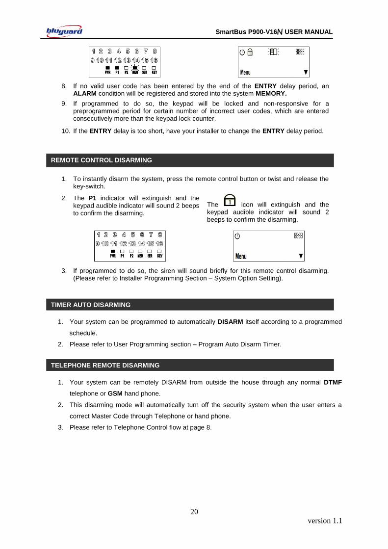
1. To instantly disarm the system, press the remote control button or twist and release the key-switch.
2. The P1 indicator will extinguish and the keypad audible indicator will sound 2 beeps to confirm the disarming.
The icon will extinguish and the keypad audible indicator will sound 2 beeps to confirm the disarming.
3. If programmed to do so, the siren will sound briefly for this remote control disarming. (Please refer to Installer Programming Section – System Option Setting).
1. Your system can be programmed to automatically DISARM itself according to a programmed
schedule.
2. Please refer to User Programming section – Program Auto Disarm Timer.
1. Your system can be remotely DISARM from outside the house through any normal DTMF
telephone or GSM hand phone.
2. This disarming mode will automatically turn off the security system when the user enters a
correct Master Code through Telephone or hand phone.
3. Please refer to Telephone Control flow at page 8.
TELEPHONE REMOTE DISARMING
REMOTE CONTROL DISARMING
TIMER AUTO DISARMING
version 1.1
21
SmartBus P900-V16N USER MANUAL
[5] + [HA POINT NUMBERS] + [#]
(Press and hold down for 2 seconds) (1 to 16)
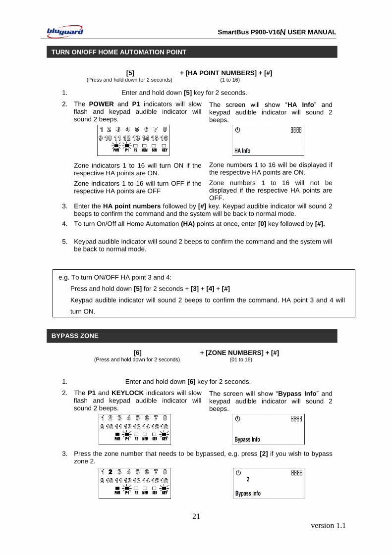
1. Enter and hold down [5] key for 2 seconds.
2. The POWER and P1 indicators will slow flash and keypad audible indicator will sound 2 beeps.
The screen will show “HA Info” and keypad audible indicator will sound 2 beeps.
Zone indicators 1 to 16 will turn ON if the respective HA points are ON.
Zone numbers 1 to 16 will be displayed if the respective HA points are ON.
Zone indicators 1 to 16 will turn OFF if the respective HA points are OFF
Zone numbers 1 to 16 will not be displayed if the respective HA points are OFF.
3. Enter the HA point numbers followed by [#] key. Keypad audible indicator will sound 2 beeps to confirm the command and the system will be back to normal mode.
4. To turn On/Off all Home Automation (HA) points at once, enter [0] key followed by [#].
5. Keypad audible indicator will sound 2 beeps to confirm the command and the system will be back to normal mode.
e.g. To turn ON/OFF HA point 3 and 4:
Press and hold down [5] for 2 seconds + [3] + [4] + [#]
Keypad audible indicator will sound 2 beeps to confirm the command. HA point 3 and 4 will
turn ON.
[6] + [ZONE NUMBERS] + [#] (Press and hold down for 2 seconds) (01 to 16)
1. Enter and hold down [6] key for 2 seconds.
2. The P1 and KEYLOCK indicators will slow flash and keypad audible indicator will sound 2 beeps.
The screen will show “Bypass Info” and keypad audible indicator will sound 2 beeps.
3. Press the zone number that needs to be bypassed, e.g. press [2] if you wish to bypass zone 2.
TURN ON/OFF HOME AUTOMATION POINT
BYPASS ZONE
version 1.1
22
SmartBus P900-V16N USER MANUAL
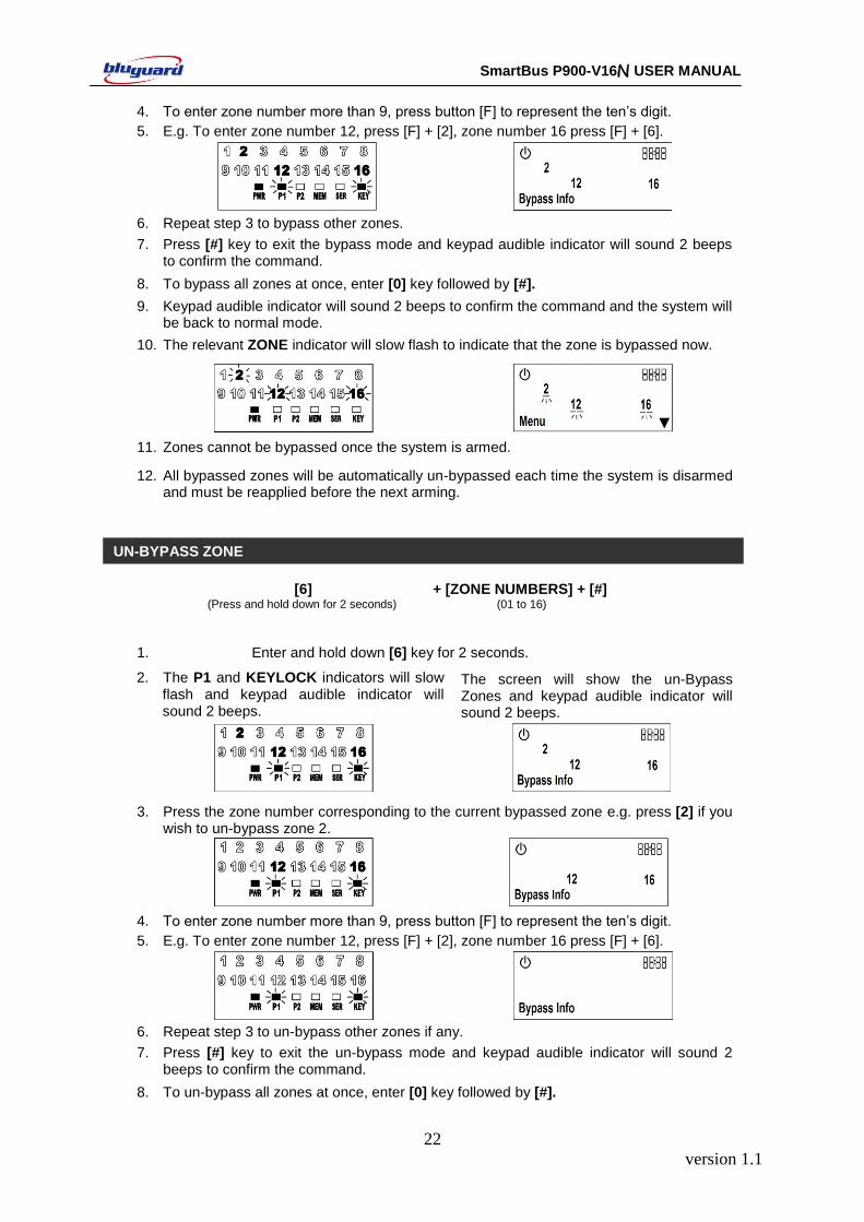
4. To enter zone number more than 9, press button [F] to represent the ten’s digit.
5. E.g. To enter zone number 12, press [F] + [2], zone number 16 press [F] + [6].
6. Repeat step 3 to bypass other zones.
7. Press [#] key to exit the bypass mode and keypad audible indicator will sound 2 beeps to confirm the command.
8. To bypass all zones at once, enter [0] key followed by [#].
9. Keypad audible indicator will sound 2 beeps to confirm the command and the system will be back to normal mode.
10. The relevant ZONE indicator will slow flash to indicate that the zone is bypassed now.
11. Zones cannot be bypassed once the system is armed.
12. All bypassed zones will be automatically un-bypassed each time the system is disarmed and must be reapplied before the next arming.
[6] + [ZONE NUMBERS] + [#] (Press and hold down for 2 seconds) (01 to 16)
1. Enter and hold down [6] key for 2 seconds.
2. The P1 and KEYLOCK indicators will slow flash and keypad audible indicator will sound 2 beeps.
The screen will show the un-Bypass Zones and keypad audible indicator will sound 2 beeps.
3. Press the zone number corresponding to the current bypassed zone e.g. press [2] if you wish to un-bypass zone 2.
4. To enter zone number more than 9, press button [F] to represent the ten’s digit.
5. E.g. To enter zone number 12, press [F] + [2], zone number 16 press [F] + [6].
6. Repeat step 3 to un-bypass other zones if any.
7. Press [#] key to exit the un-bypass mode and keypad audible indicator will sound 2 beeps to confirm the command.
8. To un-bypass all zones at once, enter [0] key followed by [#].
UN-BYPASS ZONE

version 1.1
23
SmartBus P900-V16N USER MANUAL
9. Keypad audible indicator will sound 2 beeps to confirm the command and the system will be back to normal mode.
10. The relevant ZONE indicator will extinguish to indicate that the zone is now active.
[7] (Press and hold down for 2 seconds)
1. The system will monitor a number of possible trouble conditions. If one of these
conditions occurs, the following events will occur.
2. The SERVICE indicator turns ON. The icon displayed.
The SERVICE indicator will illuminate until the trouble is restored. The icon will display until the trouble
is restored.
3. Enter and hold down [7] key for 2 seconds.
The SERVICE and KEYLOCK indicators will slow flash and keypad audible indicator will sound 2 beeps.
The screen will show the service indicator and keypad audible indicator will sound 2 beeps.
One or more ZONE indicators will turn ON to indicate the troubles occur e.g zone number 2 turning ON indicate Real Time Clock Loss (refer table below).
The trouble occurred will be displayed. Press the [▼] key to check on all the troubles that need to be serviced.
4. Press [#] key to exit and keypad audible indicator will sound 2 beeps.
ZONE 1 indicator AC Loss
ZONE 2 indicator Real Time Clock Loss (Program System Timer - refer to page 24)
ZONE 3 indicator Siren Fail
ZONE 4 indicator Battery Low Voltage
ZONE 5 indicator Telephone Line/GSM CMS Reporting Fail
ZONE 6 indicator Telephone Line/GSM Personal Reporting Fail
ZONE 7 indicator Telephone Line Connection Fail Remark: Zone 1, 2, 3 and 4 indicators will only be extinguished after the troubles are restored.
Zone 5, 6 and 7 indicators will be extinguished when they are viewed once.
VIEW SYSTEM TROUBLE
version 1.1
24
SmartBus P900-V16N USER MANUAL
[8] (Press and hold down for 2 seconds)
1. The system alarm memory will store the most recent alarm condition. An alarm condition
will cause the following events.
2. The MEMORY indicator slow flash.
The icon flash.
The MEMORY indicator will extinguish once the user enters VIEW ALARM MEMORY mode.
The icon will extinguish once the user enters VIEW ALARM MEMORY mode.
3. Enter and hold down [8] key for 2 seconds.
The MEMORY indicator will turn ON and keypad audible indicator will sound 2 beeps.
The screen will show “Alarm Memory” and keypad audible indicator will sound 2 beeps.
One or more ZONE indicators will turn ON to indicate the zones that cause the most recent alarm.
One or more ZONE numbers will be displayed to indicate the zones that cause the most recent alarm.
4. Press [#] key to exit and keypad audible indicator will sound 2 beeps.
The chime mode allows user to monitor nominated zones while the system is disarmed. The audible
indicator will sound briefly when the nominated zone is violated – the siren will NOT sound. If you wish
to know there is someone enters or exits the front door, the keypad will beep once when the door is
opened provided the zone is a chime zone.
[9] + [ZONE NUMBERS] + [#]
(Press and hold down for 2 seconds) (01 to 16)
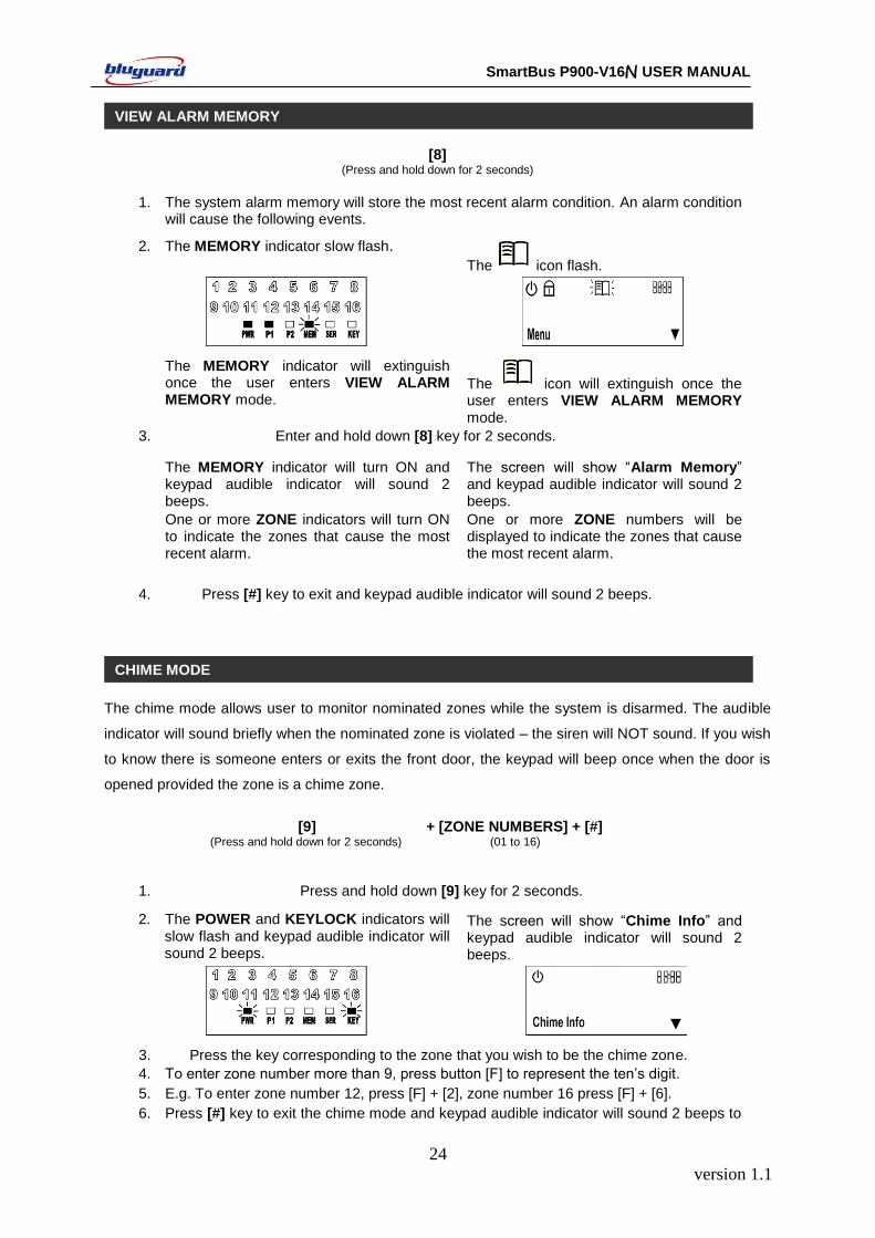
1. Press and hold down [9] key for 2 seconds.
2. The POWER and KEYLOCK indicators will slow flash and keypad audible indicator will sound 2 beeps.
The screen will show “Chime Info” and keypad audible indicator will sound 2 beeps.
3. Press the key corresponding to the zone that you wish to be the chime zone.
4. To enter zone number more than 9, press button [F] to represent the ten’s digit.
5. E.g. To enter zone number 12, press [F] + [2], zone number 16 press [F] + [6].
6. Press [#] key to exit the chime mode and keypad audible indicator will sound 2 beeps to
CHIME MODE
VIEW ALARM MEMORY
version 1.1
25
SmartBus P900-V16N USER MANUAL
confirm the command.
e.g. To program zone 3 and zone 4 as CHIME zones: Press and hold down [9] for 2 seconds + [3] + [4] + [#]
Keypad audible indicator will sound 2 beeps to confirm the command. Zone 3 and 4 are now CHIME zones.
TO CANCEL CHIME ZONE: Repeat the above steps and ensure that the zone indicator/display is extinguished.
FIRE MODE
[F] (Press and hold down for 2 seconds)
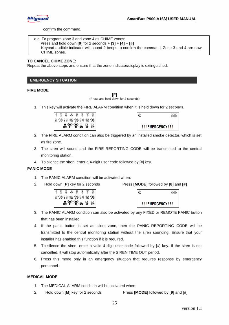
1. This key will activate the FIRE ALARM condition when it is held down for 2 seconds.
2. The FIRE ALARM condition can also be triggered by an installed smoke detector, which is set
as fire zone.
3. The siren will sound and the FIRE REPORTING CODE will be transmitted to the central
monitoring station.
4. To silence the siren, enter a 4-digit user code followed by [#] key.
PANIC MODE
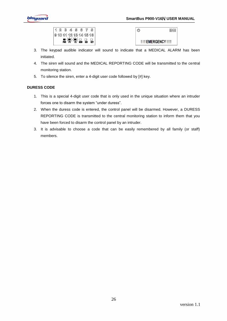
1. The PANIC ALARM condition will be activated when:
2. Hold down [P] key for 2 seconds Press [MODE] followed by [8] and [#]
3. The PANIC ALARM condition can also be activated by any FIXED or REMOTE PANIC button
that has been installed.
4. If the panic button is set as silent zone, then the PANIC REPORTING CODE will be
transmitted to the central monitoring station without the siren sounding. Ensure that your
installer has enabled this function if it is required.
5. To silence the siren, enter a valid 4-digit user code followed by [#] key. If the siren is not
cancelled, it will stop automatically after the SIREN TIME OUT period.
6. Press this mode only in an emergency situation that requires response by emergency
personnel.
MEDICAL MODE
1. The MEDICAL ALARM condition will be activated when:
2. Hold down [M] key for 2 seconds Press [MODE] followed by [9] and [#]
EMERGENCY SITUATION Indicate the status of the zones
OMEMORY INDICATOR (Orange)
The indicator will slow flash when the alarm is triggered
NSERVICE INDICATOR (Orange)
The indicator is illuminated when the system is in trouble condition
SPOWER INDICATOR (GREEN)
The indicator is illuminated when AC power is present
ARMED INDICATOR (Red) The indicator is illuminated when the system is armed
version 1.1
26
SmartBus P900-V16N USER MANUAL
3. The keypad audible indicator will sound to indicate that a MEDICAL ALARM has been
initiated.
4. The siren will sound and the MEDICAL REPORTING CODE will be transmitted to the central
monitoring station.
5. To silence the siren, enter a 4-digit user code followed by [#] key.
DURESS CODE
1. This is a special 4-digit user code that is only used in the unique situation where an intruder
forces one to disarm the system “under duress”.
2. When the duress code is entered, the control panel will be disarmed. However, a DURESS
REPORTING CODE is transmitted to the central monitoring station to inform them that you
have been forced to disarm the control panel by an intruder.
3. It is advisable to choose a code that can be easily remembered by all family (or staff)
members.

version 1.1
27
SmartBus P900-V16N USER MANUAL
Depending on your needs, your installer can program your control panel to recognize and control 2
separate areas (Partition 1 and Partition 2) by activating the system’s partitioning feature. User codes
can also be programmed to ARM/DISARM one partition or both partitions simultaneously.
You can use partitioning in installations where shared systems are more practical, such as
office/warehouse buildings, or apartment/condominium complexes.
Zones can be divided into two systems. Based on your requirements, the installer designates which
zones belong to Partition 1 and Partition 2, both partitions (dual area), or are not given any partition
assignment. A zone belonging to a 2 partitions is armed only when both Partition 1 and Partition 2 are
armed. However, this sharing zone will be disarmed if either Partition 1 or Partition 2 is disarmed.
The installer must program the required user code settings. These settings determine which user
codes can arm Partition 1, as well as which user codes can arm Partition 2. Codes can also be given
access to both partitions.
If your user code has access to both partitions
[] + [USER CODE] + [#] + [1] + [2] (Leave via ENTRY/EXIT Zone)
1. Ensure that all zone indicators are distinguished; if not, check that all protected premises are closed.
2. Press the [*] key to cancel any unintended entries.
3. Enter a valid 4-digit [USER CODE]. If you enter mistakes, press [*] key and re-enter the code followed by [#] key to confirm your command.
4. If the key in user code is assigned to control 2 partitions:
Zone indicators 1 and 2 will flash. P1 and P2 options will be displayed.
5. Enter key [1] followed by key [2].
The P1 and P2 indicators will illuminate.
and icons will be displayed.
An EXIT delay countdown timer will be
PARTITIONING THE SYSTEM
ARMING A PARTITIONED SYSTEM
AWAY ARMING 2 PARTITIONS SIMULTANEOUSLY
version 1.1
28
SmartBus P900-V16N USER MANUAL
shown at the top right temporarily replace the clock.
6. The keypad audible indicator will sound on and off for the duration of the EXIT delay.
7. Any bypassed zones will be shown by the flashing zone indicators.
8. Leave the premises only via the EXIT/ENTRY zone.
9. During AWAY arming, the telephone line will be supervised hourly. If the telephone line is disconnected, a new trouble condition will be registered (please refer to View System Trouble).
10. User will be given an ENTRY delay time to disarm the system when enter the protected premises via ENTRY/EXIT zone.
11. It is also possible to AWAY arm by simply enter and hold down [1] key for 2 seconds.
[1] + [1 or 2] (Press and hold down for 2 seconds)
12. Zone indicator [1] and [2] will flash. P1 and P2 options will be displayed.
Enter key [1] followed by key [2] to arm both partitions.
If your user code has access to 2 partitions and you would like to arm Partition 1 only
[] + [USER CODE] + [#] + [1] + [#] (Leave via ENTRY/EXIT Zone)
If your user code has access to 2 partitions and you would like to arm Partition 2 only
[] + [USER CODE] + [#] + [2] + [#] (Leave via ENTRY/EXIT Zone)
1. Ensure that all zone indicators are distinguished; if not, check that all protected premises
are closed.
2. Press the [*] key to cancel any unintended entries.
3. Enter a valid 4-digit [USER CODE]. If you enter mistakes, press [*] key and re-enter the code followed by [#] key to confirm your command.
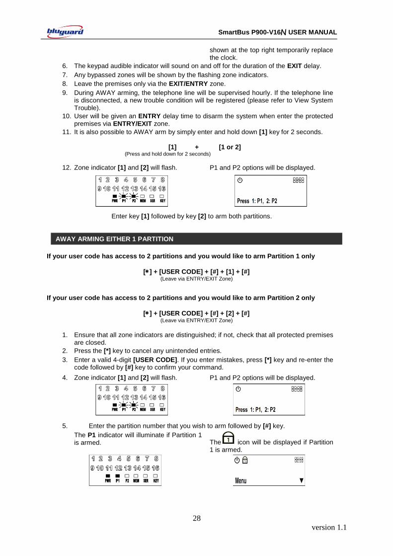
4. Zone indicator [1] and [2] will flash. P1 and P2 options will be displayed.
5. Enter the partition number that you wish to arm followed by [#] key.
The P1 indicator will illuminate if Partition 1 is armed. The icon will be displayed if Partition
1 is armed.
AWAY ARMING EITHER 1 PARTITION
version 1.1
29
SmartBus P900-V16N USER MANUAL
An EXIT delay countdown timer will be shown at the top right temporarily replace the clock.
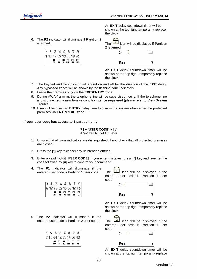
6. The P2 indicator will illuminate if Partition 2 is armed. The icon will be displayed if Partition
2 is armed.
An EXIT delay countdown timer will be shown at the top right temporarily replace the clock.
7. The keypad audible indicator will sound on and off for the duration of the EXIT delay. Any bypassed zones will be shown by the flashing zone indicators.
8. Leave the premises only via the EXIT/ENTRY zone.
9. During AWAY arming, the telephone line will be supervised hourly. If the telephone line is disconnected, a new trouble condition will be registered (please refer to View System Trouble).
10. User will be given an ENTRY delay time to disarm the system when enter the protected premises via ENTRY/EXIT zone.
If your user code has access to 1 partition only
[] + [USER CODE] + [#] (Leave via ENTRY/EXIT Zone)
1. Ensure that all zone indicators are distinguished; if not, check that all protected premises
are closed.
2. Press the [*] key to cancel any unintended entries.
3. Enter a valid 4-digit [USER CODE]. If you enter mistakes, press [*] key and re-enter the code followed by [#] key to confirm your command.
4. The P1 indicator will illuminate if the entered user code is Partition 1 user code. The icon will be displayed if the
entered user code is Partition 1 user code.
An EXIT delay countdown timer will be shown at the top right temporarily replace the clock.
5. The P2 indicator will illuminate if the entered user code is Partition 2 user code. The icon will be displayed if the
entered user code is Partition 1 user code.
An EXIT delay countdown timer will be shown at the top right temporarily replace
version 1.1
30
SmartBus P900-V16N USER MANUAL
the clock.
6. The keypad audible indicator will sound on and off for the duration of the EXIT delay. Any bypassed zones will be shown by the flashing zone indicators.
7. Leave the premises only via the EXIT/ENTRY zone.
8. During AWAY arming, the telephone line will be supervised hourly. If the telephone line is disconnected, a new trouble condition will be registered (please refer to View System Trouble).
9. User will be given an ENTRY delay time to disarm the system when enter the protected premises via ENTRY/EXIT zone.
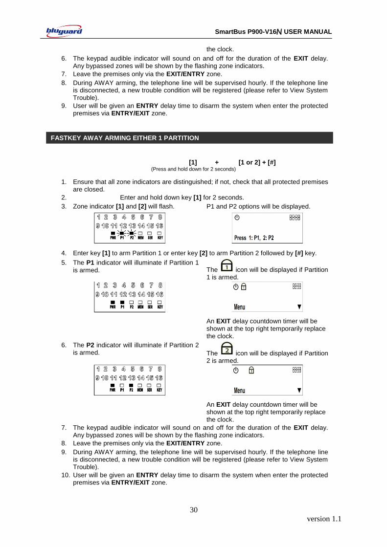
[1] + [1 or 2] + [#] (Press and hold down for 2 seconds)
1. Ensure that all zone indicators are distinguished; if not, check that all protected premises are closed.
2. Enter and hold down key [1] for 2 seconds.
3. Zone indicator [1] and [2] will flash. P1 and P2 options will be displayed.
4. Enter key [1] to arm Partition 1 or enter key [2] to arm Partition 2 followed by [#] key.
5. The P1 indicator will illuminate if Partition 1 is armed. The icon will be displayed if Partition
1 is armed.
An EXIT delay countdown timer will be shown at the top right temporarily replace the clock.
6. The P2 indicator will illuminate if Partition 2 is armed. The icon will be displayed if Partition
2 is armed.
An EXIT delay countdown timer will be shown at the top right temporarily replace the clock.
7. The keypad audible indicator will sound on and off for the duration of the EXIT delay. Any bypassed zones will be shown by the flashing zone indicators.
8. Leave the premises only via the EXIT/ENTRY zone.
9. During AWAY arming, the telephone line will be supervised hourly. If the telephone line is disconnected, a new trouble condition will be registered (please refer to View System Trouble).
10. User will be given an ENTRY delay time to disarm the system when enter the protected premises via ENTRY/EXIT zone.
FASTKEY AWAY ARMING EITHER 1 PARTITION
version 1.1
31
SmartBus P900-V16N USER MANUAL
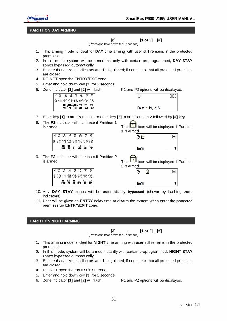
[2] + [1 or 2] + [#] (Press and hold down for 2 seconds)
1. This arming mode is ideal for DAY time arming with user still remains in the protected premises.
2. In this mode, system will be armed instantly with certain preprogrammed, DAY STAY zones bypassed automatically.
3. Ensure that all zone indicators are distinguished; if not, check that all protected premises are closed.
4. DO NOT open the ENTRY/EXIT zone.
5. Enter and hold down key [2] for 2 seconds.
6. Zone indicator [1] and [2] will flash. P1 and P2 options will be displayed.
7. Enter key [1] to arm Partition 1 or enter key [2] to arm Partition 2 followed by [#] key.
8. The P1 indicator will illuminate if Partition 1 is armed. The icon will be displayed if Partition
1 is armed.
9. The P2 indicator will illuminate if Partition 2 is armed. The icon will be displayed if Partition
2 is armed.
10. Any DAY STAY zones will be automatically bypassed (shown by flashing zone indicators).
11. User will be given an ENTRY delay time to disarm the system when enter the protected premises via ENTRY/EXIT zone.
[3] + [1 or 2] + [#] (Press and hold down for 2 seconds)
1. This arming mode is ideal for NIGHT time arming with user still remains in the protected premises.
2. In this mode, system will be armed instantly with certain preprogrammed, NIGHT STAY zones bypassed automatically.
3. Ensure that all zone indicators are distinguished; if not, check that all protected premises are closed.
4. DO NOT open the ENTRY/EXIT zone.
5. Enter and hold down key [3] for 2 seconds.
6. Zone indicator [1] and [2] will flash. P1 and P2 options will be displayed.
PARTITION DAY ARMING
PARTITION NIGHT ARMING

version 1.1
32
SmartBus P900-V16N USER MANUAL
7. Enter key [1] to arm Partition 1 or enter key [2] to arm Partition 2 followed by [#] key.
8. The P1 indicator will illuminate if Partition 1 is armed. The icon will be displayed if Partition
1 is armed.
9. The P2 indicator will illuminate if Partition 2 is armed. The icon will be displayed if Partition
2 is armed.
10. Any NIGHT STAY zones will be automatically bypassed (shown by flashing zone indicators).
11. There is no ENTRY delay in this arming mode. Any violation on the active zones will trigger the system instantly.
[4] + [1 or 2] + [#] (Press and hold down for 2 seconds)
1. In this mode, the system will be armed with EXIT delay time which allows certain violated zones to be bypassed temporary. When the violated zones resume, the zone will be protected again.
2. Enter and hold down key [4] for 2 seconds.
3. Zone indicator [1] and [2] will flash. P1 and P2 options will be displayed.
4. Enter key [1] to arm Partition 1 or enter key [2] to arm Partition 2 followed by [#] key.
5. The P1 indicator will illuminate if Partition 1 is armed. The icon will be displayed if Partition
1 is armed.
An EXIT delay countdown timer will be shown at the top right temporarily replace the clock.
6. The P2 indicator will illuminate if Partition 2 is armed. The icon will be displayed if Partition
2 is armed.
PARTITION FORCE ARMING
version 1.1
33
SmartBus P900-V16N USER MANUAL
An EXIT delay countdown timer will be shown at the top right temporarily replace the clock.
7. Keypad audible indicator will sound on and off for the duration of the EXIT delay. Any bypassed zones will be shown by the flashing zone indicators.
8. User will be given an ENTRY delay time to disarm the system when enter the protected premises via ENTRY/EXIT zone.
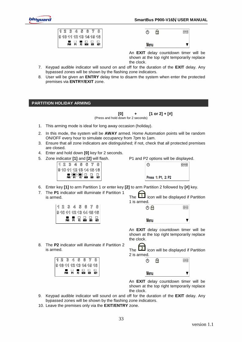
[0] + [1 or 2] + [#] (Press and hold down for 2 seconds)
1. This arming mode is ideal for long away occasion (holiday).
2. In this mode, the system will be AWAY armed. Home Automation points will be random ON/OFF every hour to simulate occupancy from 7pm to 1am.
3. Ensure that all zone indicators are distinguished; if not, check that all protected premises are closed.
4. Enter and hold down [0] key for 2 seconds.
5. Zone indicator [1] and [2] will flash. P1 and P2 options will be displayed.
6. Enter key [1] to arm Partition 1 or enter key [2] to arm Partition 2 followed by [#] key.
7. The P1 indicator will illuminate if Partition 1 is armed. The icon will be displayed if Partition
1 is armed.
An EXIT delay countdown timer will be shown at the top right temporarily replace the clock.
8. The P2 indicator will illuminate if Partition 2 is armed. The icon will be displayed if Partition
2 is armed.
An EXIT delay countdown timer will be shown at the top right temporarily replace the clock.
9. Keypad audible indicator will sound on and off for the duration of the EXIT delay. Any bypassed zones will be shown by the flashing zone indicators.
10. Leave the premises only via the EXIT/ENTRY zone.
PARTITION HOLIDAY ARMING
version 1.1
34
SmartBus P900-V16N USER MANUAL
11. User will be given an ENTRY delay time to disarm the system when enter the protected premises via ENTRY/EXIT zone.
12. After disarming, Home Automation random ON/OFF function will be deactivated and the system will resume to normal Home Automation ON/OFF timers setting.
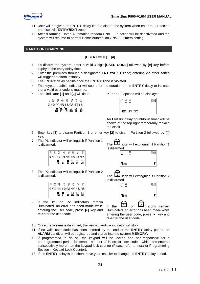
[USER CODE] + [#] 1. To disarm the system, enter a valid 4-digit [USER CODE] followed by [#] key before
expiry of the entry delay time.
2. Enter the premises through a designated ENTRY/EXIT zone; entering via other zones will trigger an alarm instantly.
3. The ENTRY delay begins once the ENTRY zone is violated.
4. The keypad audible indicator will sound for the duration of the ENTRY delay to indicate that a valid user code is required.
5. Zone indicator [1] and [2] will flash. P1 and P2 options will be displayed.
An ENTRY delay countdown timer will be shown at the top right temporarily replace the clock.
6. Enter key [1] to disarm Partition 1 or enter key [2] to disarm Partition 2 followed by [#] key.
7. The P1 indicator will extinguish if Partition 1 is disarmed. The icon will extinguish if Partition 1
is disarmed.
8. The P2 indicator will extinguish if Partition 2 is disarmed. The icon will extinguish if Partition 2
is disarmed.
9. If the P1 or P2 indicators remain illuminated, an error has been made while
entering the user code, press [] key and re-enter the user code.
If the or icons remain illuminated, an error has been made while
entering the user code, press [] key and re-enter the user code.
10. Once the system is disarmed, the keypad audible indicator will stop.
11. If no valid user code has been entered by the end of the ENTRY delay period, an ALARM condition will be registered and stored into the system MEMORY.
12. If programmed to do so, the keypad will be locked and non-responsive for a preprogrammed period for certain number of incorrect user codes, which are entered consecutively more than the keypad lock counter (Please refer to Installer Programming Section – Keypad Lock Counter).
13. If the ENTRY delay is too short, have your installer to change the ENTRY delay period.
PARTITION DISARMING
version 1.1
35
SmartBus P900-V16N USER MANUAL
14. If the MEMORY indicator is flashing upon entry, there has been an intrusion. Call for assistance. The intruder may still be inside.
Master code is a 4-digit personal identification number that allows you to enter certain programming
mode, arm or disarm the system and remotely control the system via telephone line. In additional to
Master Code, P900-V16N can be programmed to accept 13 user codes that allow you to arm/disarm
the system. The default Master Code is “1234”.
Door Access Code is a special 4-digit code that allows you to control a single door access system.
The Door Access Code cannot arm or disarm the security system.
Duress Code is an ambush code which will disarm the system and simultaneously send a silent alarm
signal to the center monitoring station. It is very useful code when you are forced to disarm your
security system under threat.
[] + [MODE] + [USER MASTER CODE] + [#]
1. Ensure that the system is not ARMED.
2. Press the [] key to cancel any unintended entries.
3. Press [MODE] key to go into USER PROGRAMMING mode.
4. Enter a valid 4-digit [USER MASTER CODE]. If you enter any mistakes, press [] key
and repeat step 3.
5. If a wrong USER MASTER CODE is entered, a long beep will be sound. Repeat step 3-
4 to enter USER PROGRAMMING MODE.
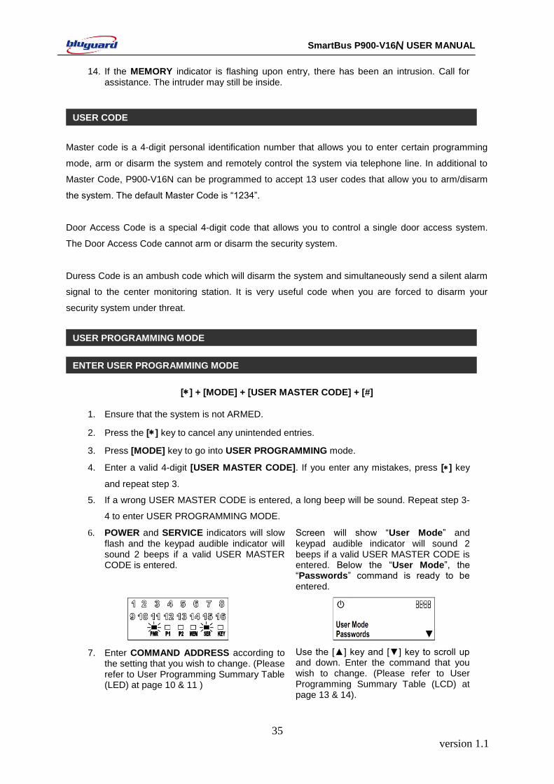
6. POWER and SERVICE indicators will slow flash and the keypad audible indicator will sound 2 beeps if a valid USER MASTER CODE is entered.
Screen will show “User Mode” and keypad audible indicator will sound 2 beeps if a valid USER MASTER CODE is entered. Below the “User Mode”, the “Passwords” command is ready to be entered.
7. Enter COMMAND ADDRESS according to the setting that you wish to change. (Please refer to User Programming Summary Table (LED) at page 10 & 11 )
Use the [▲] key and [▼] key to scroll up and down. Enter the command that you wish to change. (Please refer to User Programming Summary Table (LCD) at page 13 & 14).
USER CODE
USER PROGRAMMING MODE
ENTER USER PROGRAMMING MODE
version 1.1
36
SmartBus P900-V16N USER MANUAL
8. To exit user programming mode, press [MODE] followed by [#] key.
To exit user programming mode press []
or exit from MENU.
1. Press [MODE] followed by [#] key to exit. Press [] or exit from MENU.
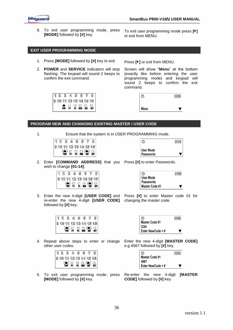
2. POWER and SERVICE indicators will stop flashing. The keypad will sound 2 beeps to confirm the exit command.
Screen will show “Menu” at the bottom (exactly like before entering the user programming mode) and keypad will sound 2 beeps to confirm the exit command.
1. Ensure that the system is in USER PROGRAMMING mode.
2. Enter [COMMAND ADDRESS] that you wish to change [01-14].
Press [#] to enter Passwords.
3. Enter the new 4-digit [USER CODE] and re-enter the new 4-digit [USER CODE] followed by [#] key.
Press [#] to enter Master code 01 for changing the master code.
4. Repeat above steps to enter or change other user codes.
Enter the new 4-digit [MASTER CODE] e.g 4567 followed by [#] key.
5. To exit user programming mode, press [MODE] followed by [#] key.
Re-enter the new 4-digit [MASTER CODE] followed by [#] key.
PROGRAM NEW AND CHANGING EXISTING MASTER / USER CODE
EXIT USER PROGRAMMING MODE
version 1.1
37
SmartBus P900-V16N USER MANUAL
6. - Use the [▲] key and [▼] key to scroll up and down to select other user code and repeat step 3.
7. - Press [] to exit user programming mode.
8. If any of the user codes are not used, please ensure that they are all erased.
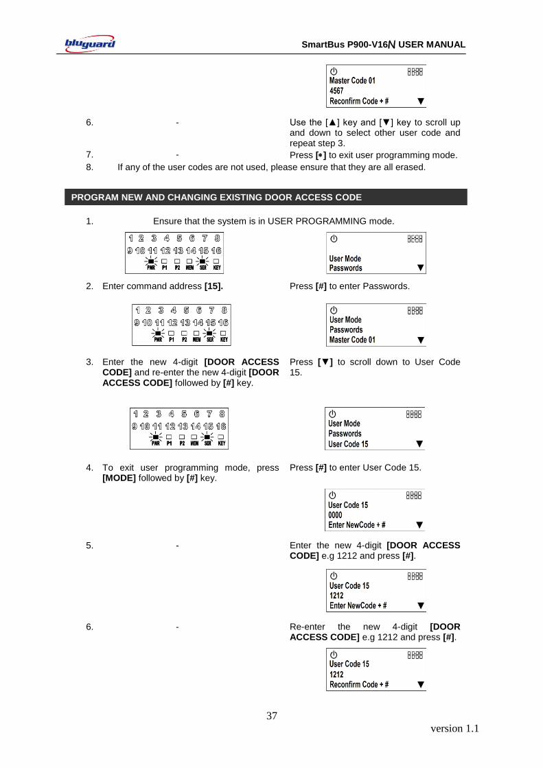
1. Ensure that the system is in USER PROGRAMMING mode.
2. Enter command address [15]. Press [#] to enter Passwords.
3. Enter the new 4-digit [DOOR ACCESS CODE] and re-enter the new 4-digit [DOOR ACCESS CODE] followed by [#] key.
Press [▼] to scroll down to User Code 15.
4. To exit user programming mode, press [MODE] followed by [#] key.
Press [#] to enter User Code 15.
5. - Enter the new 4-digit [DOOR ACCESS CODE] e.g 1212 and press [#].
6. - Re-enter the new 4-digit [DOOR ACCESS CODE] e.g 1212 and press [#].
PROGRAM NEW AND CHANGING EXISTING DOOR ACCESS CODE
version 1.1
38
SmartBus P900-V16N USER MANUAL
7. - Press [] to exit user programming mode.
8. If any of the user codes are not used, please ensure that they are all erased.
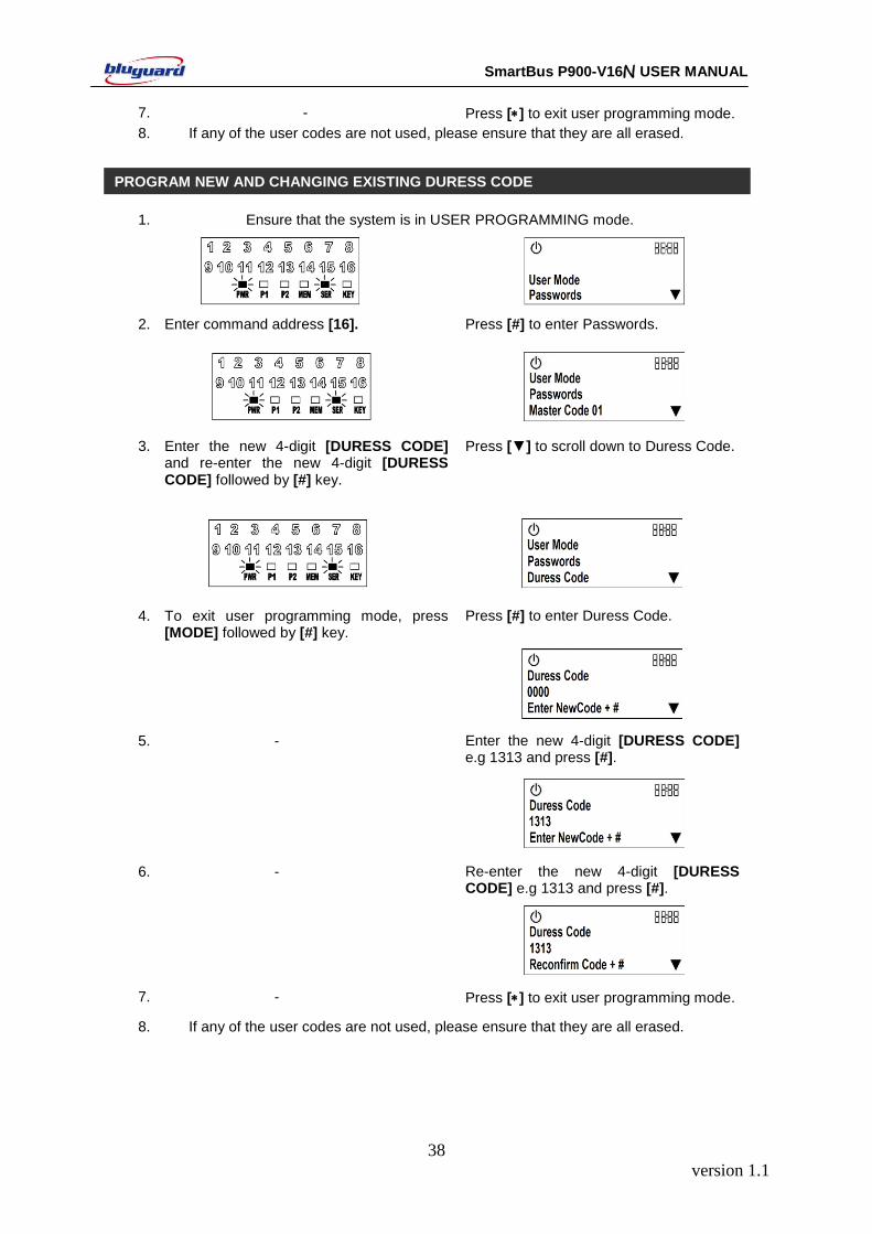
1. Ensure that the system is in USER PROGRAMMING mode.
2. Enter command address [16]. Press [#] to enter Passwords.
3. Enter the new 4-digit [DURESS CODE] and re-enter the new 4-digit [DURESS CODE] followed by [#] key.
Press [▼] to scroll down to Duress Code.
4. To exit user programming mode, press [MODE] followed by [#] key.
Press [#] to enter Duress Code.
5. - Enter the new 4-digit [DURESS CODE] e.g 1313 and press [#].
6. - Re-enter the new 4-digit [DURESS CODE] e.g 1313 and press [#].
7. - Press [] to exit user programming mode.
8. If any of the user codes are not used, please ensure that they are all erased.
PROGRAM NEW AND CHANGING EXISTING DURESS CODE
version 1.1
39
SmartBus P900-V16N USER MANUAL
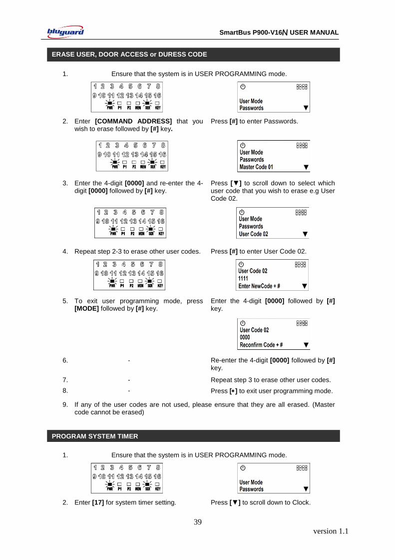
1. Ensure that the system is in USER PROGRAMMING mode.
2. Enter [COMMAND ADDRESS] that you wish to erase followed by [#] key.
Press [#] to enter Passwords.
3. Enter the 4-digit [0000] and re-enter the 4-digit [0000] followed by [#] key.
Press [▼] to scroll down to select which user code that you wish to erase e.g User Code 02.
4. Repeat step 2-3 to erase other user codes. Press [#] to enter User Code 02.
5. To exit user programming mode, press [MODE] followed by [#] key.
Enter the 4-digit [0000] followed by [#] key.
6. - Re-enter the 4-digit [0000] followed by [#] key.
7. - Repeat step 3 to erase other user codes.
8. - Press [] to exit user programming mode.
9. If any of the user codes are not used, please ensure that they are all erased. (Master code cannot be erased)
1. Ensure that the system is in USER PROGRAMMING mode.
2. Enter [17] for system timer setting. Press [▼] to scroll down to Clock.
ERASE USER, DOOR ACCESS or DURESS CODE
PROGRAM SYSTEM TIMER
version 1.1
40
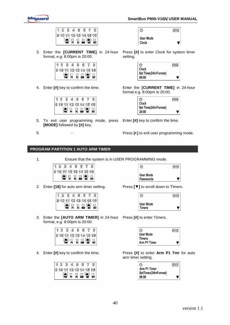
SmartBus P900-V16N USER MANUAL
3. Enter the [CURRENT TIME] in 24-hour format, e.g. 8:00pm is 20:00.
Press [#] to enter Clock for system timer setting.
4. Enter [#] key to confirm the time. Enter the [CURRENT TIME] in 24-hour format e.g. 8:00pm is 20:00.
5. To exit user programming mode, press [MODE] followed by [#] key.
Enter [#] key to confirm the time.
6. - Press [] to exit user programming mode.
1. Ensure that the system is in USER PROGRAMMING mode.
2. Enter [18] for auto arm timer setting. Press [▼] to scroll down to Timers.
3. Enter the [AUTO ARM TIMER] in 24-hour format, e.g. 8:00pm is 20:00.
Press [#] to enter Timers.
4. Enter [#] key to confirm the time. Press [#] to enter Arm P1 Tmr for auto arm timer setting.
PROGRAM PARTITION 1 AUTO ARM TIMER
version 1.1
41
SmartBus P900-V16N USER MANUAL
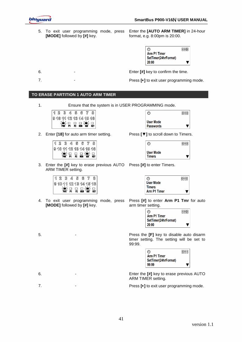
5. To exit user programming mode, press [MODE] followed by [#] key.
Enter the [AUTO ARM TIMER] in 24-hour format, e.g. 8:00pm is 20:00.
6. - Enter [#] key to confirm the time.
7. - Press [] to exit user programming mode.
1. Ensure that the system is in USER PROGRAMMING mode.
2. Enter [18] for auto arm timer setting. Press [▼] to scroll down to Timers.
3. Enter the [#] key to erase previous AUTO ARM TIMER setting.
Press [#] to enter Timers.
4. To exit user programming mode, press [MODE] followed by [#] key.
Press [#] to enter Arm P1 Tmr for auto arm timer setting.
5. - Press the [F] key to disable auto disarm timer setting. The setting will be set to 99:99.
99:99.
6. - Enter the [#] key to erase previous AUTO ARM TIMER setting.
7. - Press [] to exit user programming mode.
TO ERASE PARTITION 1 AUTO ARM TIMER
version 1.1
42
SmartBus P900-V16N USER MANUAL
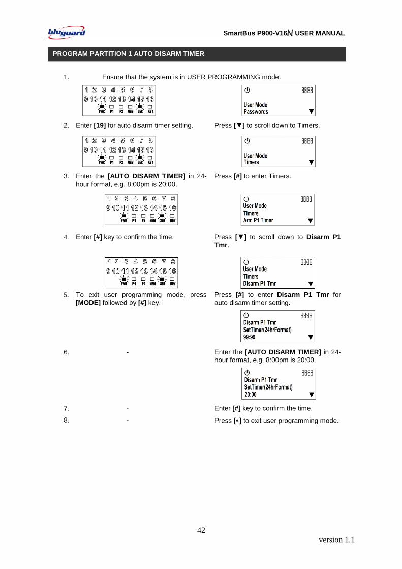
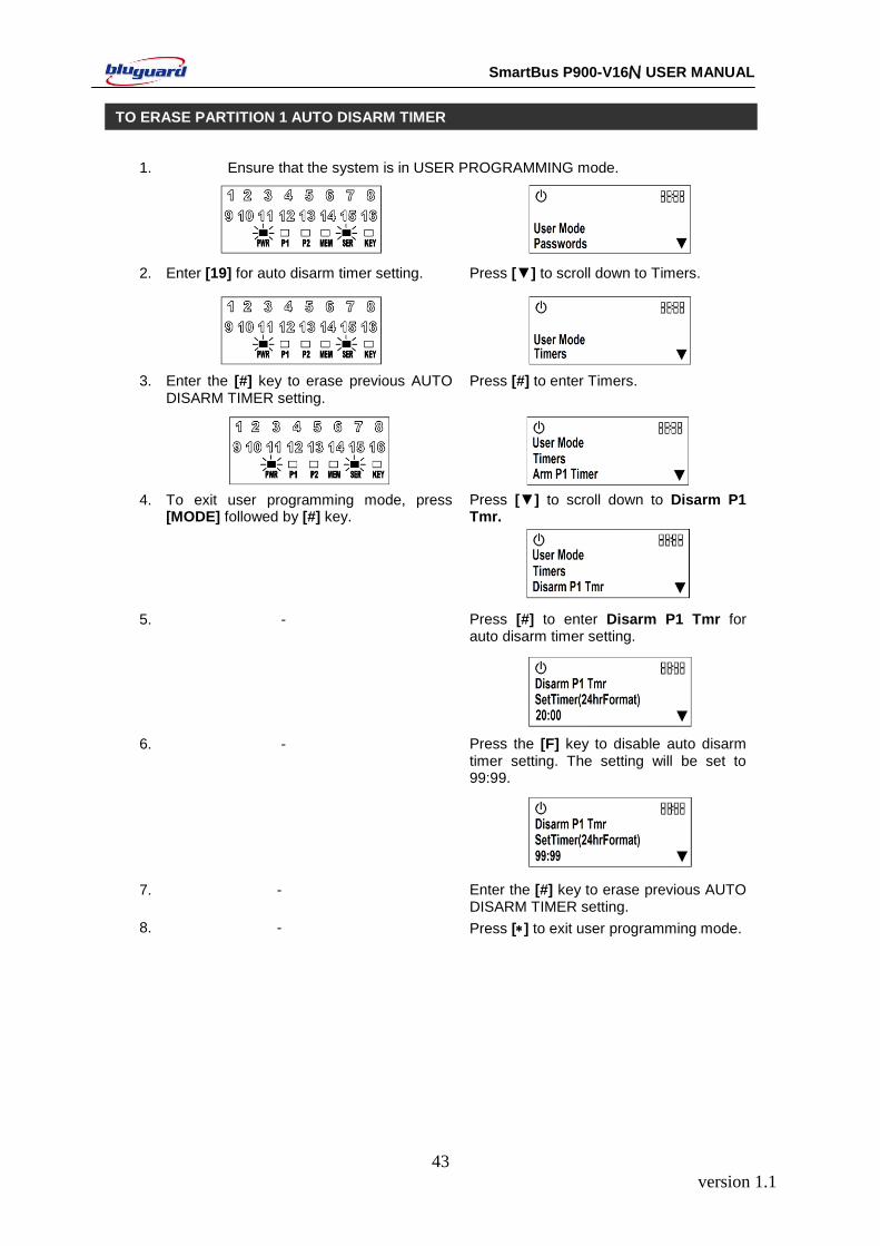
1. Ensure that the system is in USER PROGRAMMING mode.
2. Enter [19] for auto disarm timer setting. Press [▼] to scroll down to Timers.
3. Enter the [AUTO DISARM TIMER] in 24-hour format, e.g. 8:00pm is 20:00.
Press [#] to enter Timers.
4. Enter [#] key to confirm the time. Press [▼] to scroll down to Disarm P1 Tmr.
5. To exit user programming mode, press [MODE] followed by [#] key.
Press [#] to enter Disarm P1 Tmr for auto disarm timer setting.
6. - Enter the [AUTO DISARM TIMER] in 24-hour format, e.g. 8:00pm is 20:00.
7. - Enter [#] key to confirm the time.
8. - Press [] to exit user programming mode.
PROGRAM PARTITION 1 AUTO DISARM TIMER
version 1.1
43
SmartBus P900-V16N USER MANUAL
1. Ensure that the system is in USER PROGRAMMING mode.
2. Enter [19] for auto disarm timer setting. Press [▼] to scroll down to Timers.
3. Enter the [#] key to erase previous AUTO DISARM TIMER setting.
Press [#] to enter Timers.
4. To exit user programming mode, press [MODE] followed by [#] key.
Press [▼] to scroll down to Disarm P1 Tmr.
5. - Press [#] to enter Disarm P1 Tmr for auto disarm timer setting.
6. - Press the [F] key to disable auto disarm timer setting. The setting will be set to 99:99.
99:99.
7. - Enter the [#] key to erase previous AUTO DISARM TIMER setting.
8. - Press [] to exit user programming mode.
TO ERASE PARTITION 1 AUTO DISARM TIMER
version 1.1
44
SmartBus P900-V16N USER MANUAL
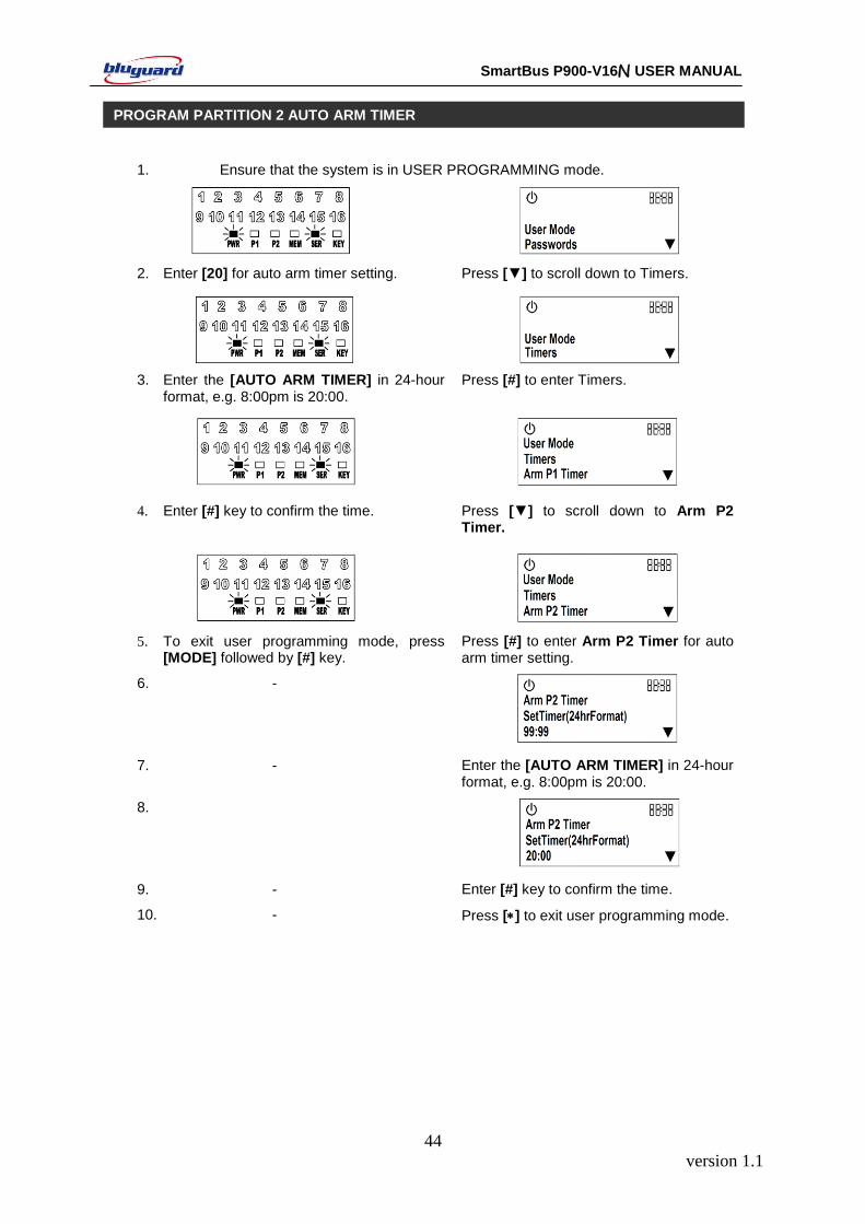
1. Ensure that the system is in USER PROGRAMMING mode.
2. Enter [20] for auto arm timer setting. Press [▼] to scroll down to Timers.
3. Enter the [AUTO ARM TIMER] in 24-hour format, e.g. 8:00pm is 20:00.
Press [#] to enter Timers.
4. Enter [#] key to confirm the time. Press [▼] to scroll down to Arm P2 Timer.
5. To exit user programming mode, press [MODE] followed by [#] key.
Press [#] to enter Arm P2 Timer for auto arm timer setting.
6. -
7. - Enter the [AUTO ARM TIMER] in 24-hour format, e.g. 8:00pm is 20:00.
8.
9. - Enter [#] key to confirm the time.
10. - Press [] to exit user programming mode.
PROGRAM PARTITION 2 AUTO ARM TIMER
version 1.1
45
SmartBus P900-V16N USER MANUAL
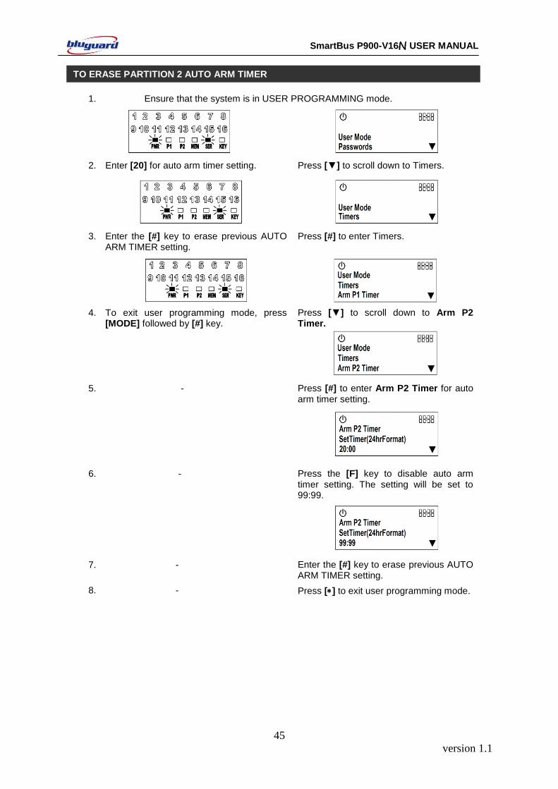
1. Ensure that the system is in USER PROGRAMMING mode.
2. Enter [20] for auto arm timer setting. Press [▼] to scroll down to Timers.
3. Enter the [#] key to erase previous AUTO ARM TIMER setting.
Press [#] to enter Timers.
4. To exit user programming mode, press [MODE] followed by [#] key.
Press [▼] to scroll down to Arm P2 Timer.
5. - Press [#] to enter Arm P2 Timer for auto arm timer setting.
6. - Press the [F] key to disable auto arm timer setting. The setting will be set to 99:99.
99:99.
7. - Enter the [#] key to erase previous AUTO ARM TIMER setting.
8. - Press [] to exit user programming mode.
TO ERASE PARTITION 2 AUTO ARM TIMER
version 1.1
46
SmartBus P900-V16N USER MANUAL
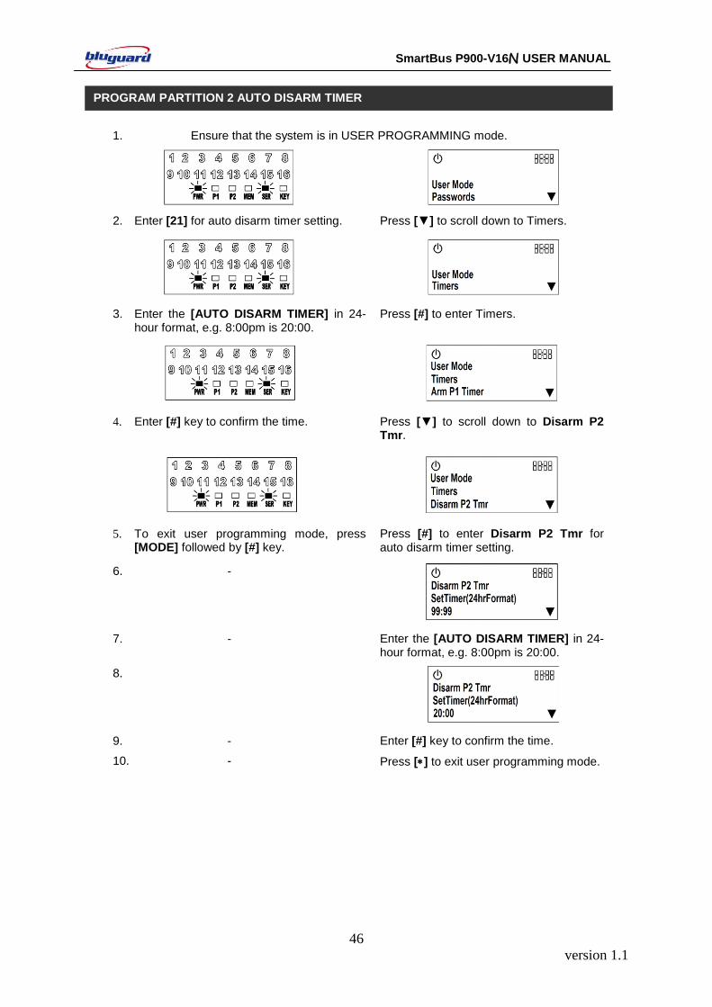
1. Ensure that the system is in USER PROGRAMMING mode.
2. Enter [21] for auto disarm timer setting. Press [▼] to scroll down to Timers.
3. Enter the [AUTO DISARM TIMER] in 24-hour format, e.g. 8:00pm is 20:00.
Press [#] to enter Timers.
4. Enter [#] key to confirm the time. Press [▼] to scroll down to Disarm P2 Tmr.
5. To exit user programming mode, press [MODE] followed by [#] key.
Press [#] to enter Disarm P2 Tmr for auto disarm timer setting.
6. -
7. - Enter the [AUTO DISARM TIMER] in 24-hour format, e.g. 8:00pm is 20:00.
8.
9. - Enter [#] key to confirm the time.
10. - Press [] to exit user programming mode.
PROGRAM PARTITION 2 AUTO DISARM TIMER

version 1.1
47
SmartBus P900-V16N USER MANUAL
1. Ensure that the system is in USER PROGRAMMING mode.
2. Enter [21] for auto disarm timer setting. Press [▼] to scroll down to Timers.
3. Enter the [#] key to erase previous AUTO DISARM TIMER setting.
Press [#] to enter Timers.
4. To exit user programming mode, press [MODE] followed by [#] key.
Press [▼] to scroll down to Disarm P2 Tmr.
5. - Press [#] to enter Disarm P2 Tmr for auto disarm timer setting.
6. - Press the [F] key to disable auto disarm timer setting. The setting will be set to 99:99.
99:99.
7. - Enter the [#] key to erase previous AUTO DISARM TIMER setting.
8. - Press [] to exit user programming mode.
TO ERASE PARTITION 2 AUTO DISARM TIMER
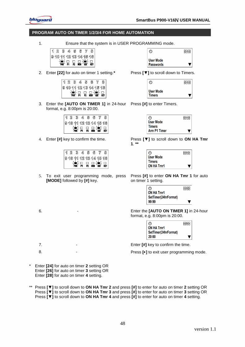
version 1.1
48
SmartBus P900-V16N USER MANUAL
1. Ensure that the system is in USER PROGRAMMING mode.
2. Enter [22] for auto on timer 1 setting.* Press [▼] to scroll down to Timers.
3. Enter the [AUTO ON TIMER 1] in 24-hour format, e.g. 8:00pm is 20:00.
Press [#] to enter Timers.
4. Enter [#] key to confirm the time. Press [▼] to scroll down to ON HA Tmr 1. **
5. To exit user programming mode, press [MODE] followed by [#] key.
Press [#] to enter ON HA Tmr 1 for auto on timer 1 setting.
6. - Enter the [AUTO ON TIMER 1] in 24-hour format, e.g. 8:00pm is 20:00.
7. - Enter [#] key to confirm the time.
8. - Press [] to exit user programming mode.
*
Enter [24] for auto on timer 2 setting OR Enter [26] for auto on timer 3 setting OR Enter [28] for auto on timer 4 setting.
**
Press [▼] to scroll down to ON HA Tmr 2 and press [#] to enter for auto on timer 2 setting OR Press [▼] to scroll down to ON HA Tmr 3 and press [#] to enter for auto on timer 3 setting OR Press [▼] to scroll down to ON HA Tmr 4 and press [#] to enter for auto on timer 4 setting.
PROGRAM AUTO ON TIMER 1/2/3/4 FOR HOME AUTOMATION
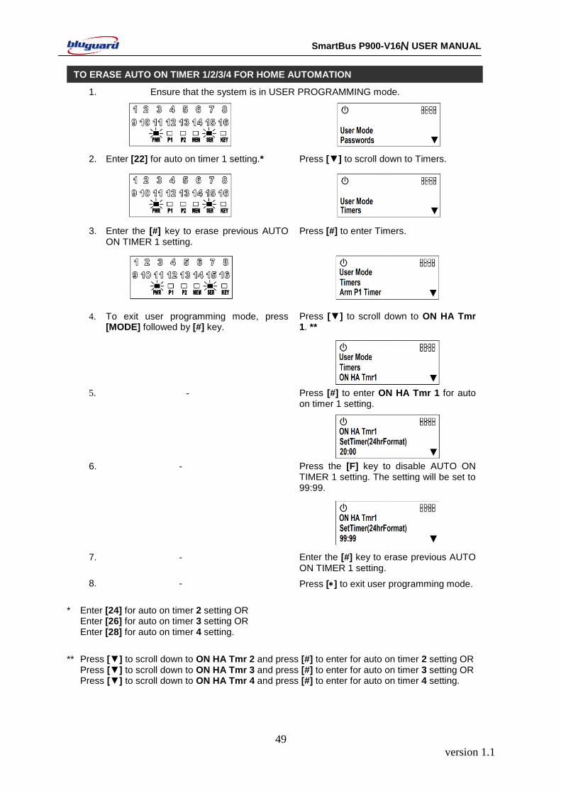
version 1.1
49
SmartBus P900-V16N USER MANUAL
1. Ensure that the system is in USER PROGRAMMING mode.
2. Enter [22] for auto on timer 1 setting.* Press [▼] to scroll down to Timers.
3. Enter the [#] key to erase previous AUTO ON TIMER 1 setting.
Press [#] to enter Timers.
4. To exit user programming mode, press [MODE] followed by [#] key.
Press [▼] to scroll down to ON HA Tmr 1. **
5. - Press [#] to enter ON HA Tmr 1 for auto on timer 1 setting.
6. - Press the [F] key to disable AUTO ON
TIMER 1 setting. The setting will be set to 99:99.
7. - Enter the [#] key to erase previous AUTO ON TIMER 1 setting.
8. - Press [] to exit user programming mode.
*
Enter [24] for auto on timer 2 setting OR
Enter [26] for auto on timer 3 setting OR Enter [28] for auto on timer 4 setting.
**
Press [▼] to scroll down to ON HA Tmr 2 and press [#] to enter for auto on timer 2 setting OR Press [▼] to scroll down to ON HA Tmr 3 and press [#] to enter for auto on timer 3 setting OR Press [▼] to scroll down to ON HA Tmr 4 and press [#] to enter for auto on timer 4 setting.
TO ERASE AUTO ON TIMER 1/2/3/4 FOR HOME AUTOMATION
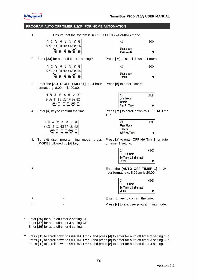
version 1.1
50
SmartBus P900-V16N USER MANUAL
1. Ensure that the system is in USER PROGRAMMING mode.
2. Enter [23] for auto off timer 1 setting.* Press [▼] to scroll down to Timers.
3. Enter the [AUTO OFF TIMER 1] in 24-hour format, e.g. 8:00pm is 20:00.
Press [#] to enter Timers.
4. Enter [#] key to confirm the time. Press [▼] to scroll down to OFF HA Tmr 1.**
5. To exit user programming mode, press [MODE] followed by [#] key.
Press [#] to enter OFF HA Tmr 1 for auto off timer 1 setting.
6. - Enter the [AUTO OFF TIMER 1] in 24-hour format, e.g. 8:00pm is 20:00.
7. - Enter [#] key to confirm the time.
8. - Press [] to exit user programming mode.
*
Enter [25] for auto off timer 2 setting OR Enter [27] for auto off timer 3 setting OR Enter [29] for auto off timer 4 setting.
**
Press [▼] to scroll down to OFF HA Tmr 2 and press [#] to enter for auto off timer 2 setting OR Press [▼] to scroll down to OFF HA Tmr 3 and press [#] to enter for auto off timer 3 setting OR Press [▼] to scroll down to OFF HA Tmr 4 and press [#] to enter for auto off timer 4 setting.
PROGRAM AUTO OFF TIMER 1/2/3/4 FOR HOME AUTOMATION
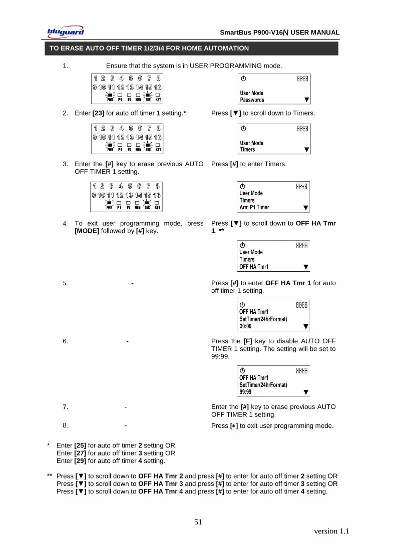
version 1.1
51
SmartBus P900-V16N USER MANUAL
1. Ensure that the system is in USER PROGRAMMING mode.
2. Enter [23] for auto off timer 1 setting.* Press [▼] to scroll down to Timers.
3. Enter the [#] key to erase previous AUTO OFF TIMER 1 setting.
Press [#] to enter Timers.
4. To exit user programming mode, press [MODE] followed by [#] key.
Press [▼] to scroll down to OFF HA Tmr 1. **
5. - Press [#] to enter OFF HA Tmr 1 for auto off timer 1 setting.
6. - Press the [F] key to disable AUTO OFF TIMER 1 setting. The setting will be set to 99:99.
7. - Enter the [#] key to erase previous AUTO OFF TIMER 1 setting.
8. - Press [] to exit user programming mode.
*
Enter [25] for auto off timer 2 setting OR
Enter [27] for auto off timer 3 setting OR Enter [29] for auto off timer 4 setting. **
Press [▼] to scroll down to OFF HA Tmr 2 and press [#] to enter for auto off timer 2 setting OR
Press [▼] to scroll down to OFF HA Tmr 3 and press [#] to enter for auto off timer 3 setting OR Press [▼] to scroll down to OFF HA Tmr 4 and press [#] to enter for auto off timer 4 setting.
TO ERASE AUTO OFF TIMER 1/2/3/4 FOR HOME AUTOMATION
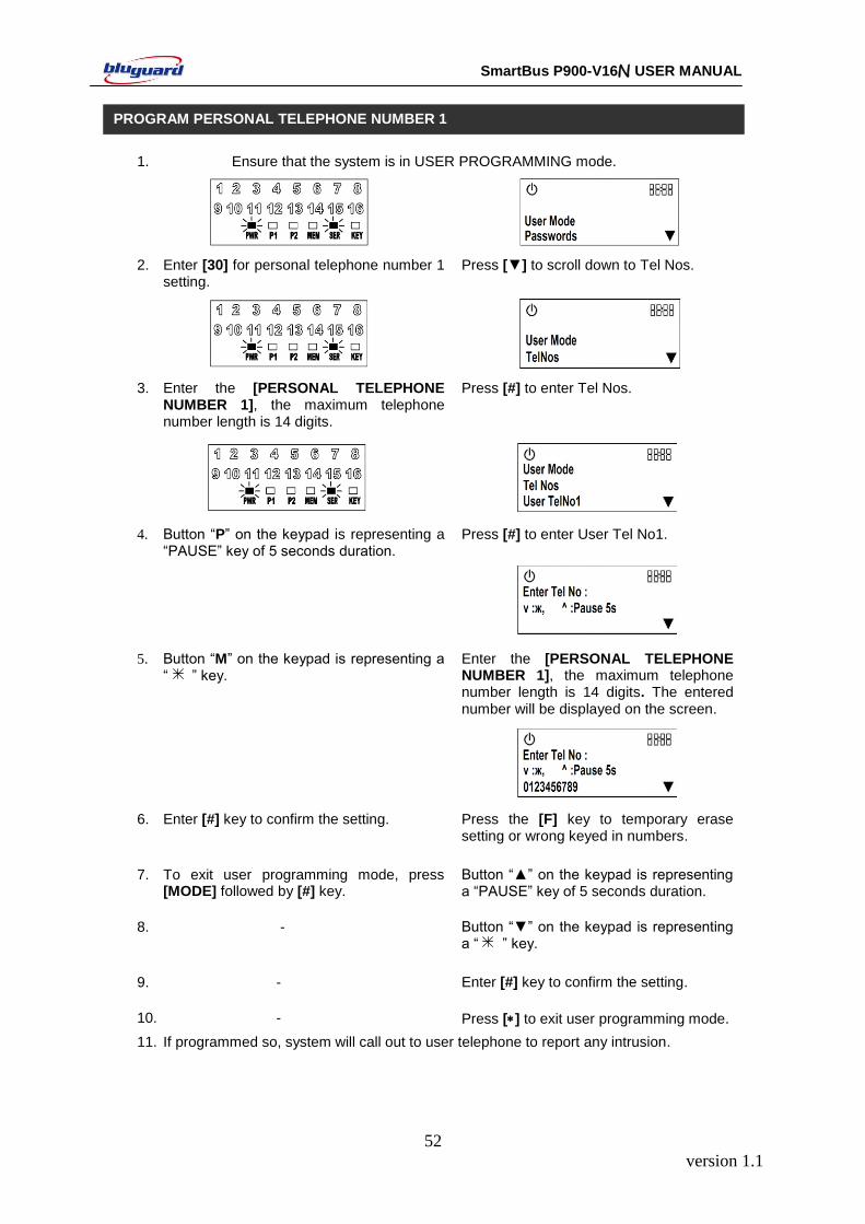
version 1.1
52
SmartBus P900-V16N USER MANUAL
1. Ensure that the system is in USER PROGRAMMING mode.
2. Enter [30] for personal telephone number 1 setting.
Press [▼] to scroll down to Tel Nos.
3. Enter the [PERSONAL TELEPHONE NUMBER 1], the maximum telephone number length is 14 digits.
Press [#] to enter Tel Nos.
4. Button “P” on the keypad is representing a “PAUSE” key of 5 seconds duration.
Press [#] to enter User Tel No1.
5. Button “M” on the keypad is representing a “ ” key.
Enter the [PERSONAL TELEPHONE NUMBER 1], the maximum telephone number length is 14 digits. The entered number will be displayed on the screen.
6. Enter [#] key to confirm the setting. Press the [F] key to temporary erase setting or wrong keyed in numbers.
7. To exit user programming mode, press [MODE] followed by [#] key.
Button “▲” on the keypad is representing a “PAUSE” key of 5 seconds duration.
8. - Button “▼” on the keypad is representing a “ ” key.
9. - Enter [#] key to confirm the setting.
10. - Press [] to exit user programming mode.
11. If programmed so, system will call out to user telephone to report any intrusion.
PROGRAM PERSONAL TELEPHONE NUMBER 1
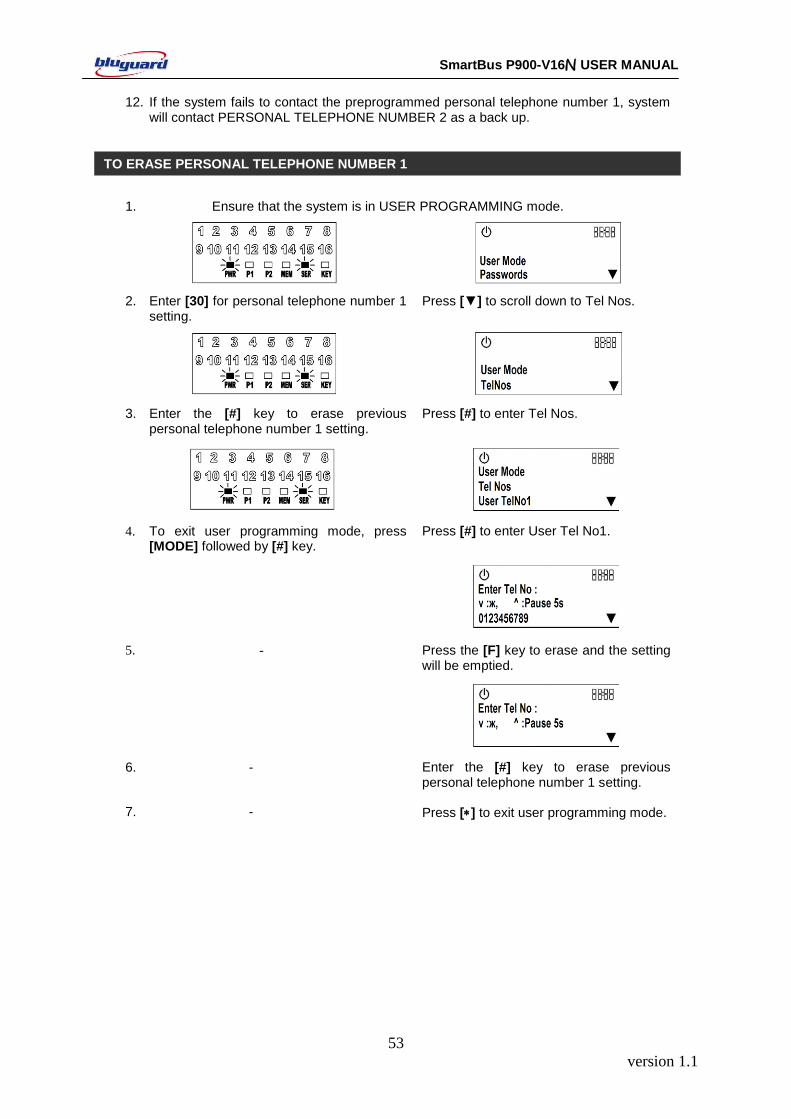
version 1.1
53
SmartBus P900-V16N USER MANUAL
12. If the system fails to contact the preprogrammed personal telephone number 1, system will contact PERSONAL TELEPHONE NUMBER 2 as a back up.
1. Ensure that the system is in USER PROGRAMMING mode.
2. Enter [30] for personal telephone number 1 setting.
Press [▼] to scroll down to Tel Nos.
3. Enter the [#] key to erase previous personal telephone number 1 setting.
Press [#] to enter Tel Nos.
4. To exit user programming mode, press [MODE] followed by [#] key.
Press [#] to enter User Tel No1.
5. - Press the [F] key to erase and the setting will be emptied.
6. - Enter the [#] key to erase previous personal telephone number 1 setting.
7. - Press [] to exit user programming mode.
TO ERASE PERSONAL TELEPHONE NUMBER 1
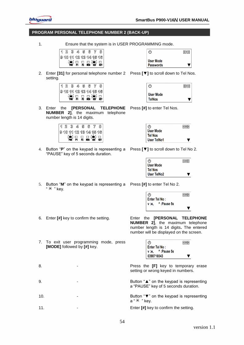
version 1.1
54
SmartBus P900-V16N USER MANUAL
1. Ensure that the system is in USER PROGRAMMING mode.
2. Enter [31] for personal telephone number 2 setting.
Press [▼] to scroll down to Tel Nos.
3. Enter the [PERSONAL TELEPHONE NUMBER 2], the maximum telephone number length is 14 digits.
Press [#] to enter Tel Nos.
4. Button “P” on the keypad is representing a “PAUSE” key of 5 seconds duration.
Press [▼] to scroll down to Tel No 2.
5. Button “M” on the keypad is representing a “ ” key.
Press [#] to enter Tel No 2.
6. Enter [#] key to confirm the setting. Enter the [PERSONAL TELEPHONE NUMBER 2], the maximum telephone number length is 14 digits. The entered number will be displayed on the screen.
7. To exit user programming mode, press [MODE] followed by [#] key.
8. - Press the [F] key to temporary erase setting or wrong keyed in numbers.
9. - Button “▲” on the keypad is representing a “PAUSE” key of 5 seconds duration.
10. - Button “▼” on the keypad is representing a “ ” key.
11. - Enter [#] key to confirm the setting.
PROGRAM PERSONAL TELEPHONE NUMBER 2 (BACK-UP)
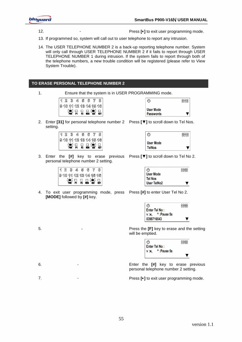
version 1.1
55
SmartBus P900-V16N USER MANUAL
12. - Press [] to exit user programming mode.
13. If programmed so, system will call out to user telephone to report any intrusion.
14. The USER TELEPHONE NUMBER 2 is a back-up reporting telephone number. System will only call through USER TELEPHONE NUMBER 2 if it fails to report through USER TELEPHONE NUMBER 1 during intrusion. If the system fails to report through both of the telephone numbers, a new trouble condition will be registered (please refer to View System Trouble).
1. Ensure that the system is in USER PROGRAMMING mode.
2. Enter [31] for personal telephone number 2 setting.
Press [▼] to scroll down to Tel Nos.
3. Enter the [#] key to erase previous personal telephone number 2 setting.
Press [▼] to scroll down to Tel No 2.
4. To exit user programming mode, press [MODE] followed by [#] key.
Press [#] to enter User Tel No 2.
5. - Press the [F] key to erase and the setting will be emptied.
6. - Enter the [#] key to erase previous personal telephone number 2 setting.
7. - Press [] to exit user programming mode.
TO ERASE PERSONAL TELEPHONE NUMBER 2
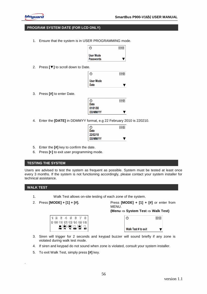
version 1.1
56
SmartBus P900-V16N USER MANUAL
1. Ensure that the system is in USER PROGRAMMING mode.
2. Press [▼] to scroll down to Date.
3. Press [#] to enter Date.
4. Enter the [DATE] in DDMMYY format, e.g 22 February 2010 is 220210.
5. Enter the [#] key to confirm the date.
6. Press [] to exit user programming mode.
7.
Users are advised to test the system as frequent as possible. System must be tested at least once every 3 months. If the system is not functioning accordingly, please contact your system installer for technical assistance.
1. Walk Test allows on-site testing of each zone of the system.
2. Press [MODE] + [1] + [#]. Press [MODE] + [1] + [#] or enter from MENU.
(Menu System Test Walk Test)
3. Siren will trigger for 2 seconds and keypad buzzer will sound briefly if any zone is violated during walk test mode.
4. If siren and keypad do not sound when zone is violated, consult your system installer.
5. To exit Walk Test, simply press [#] key.
.
TESTING THE SYSTEM
PROGRAM SYSTEM DATE (FOR LCD ONLY)
WALK TEST
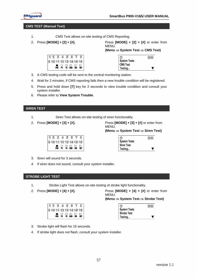
version 1.1
57
SmartBus P900-V16N USER MANUAL
1. CMS Test allows on-site testing of CMS Reporting.
2. Press [MODE] + [2] + [#]. Press [MODE] + [2] + [#] or enter from MENU.
(Menu System Test CMS Test)
3. A CMS testing code will be sent to the central monitoring station.
4. Wait for 2 minutes, if CMS reporting fails then a new trouble condition will be registered.
5. Press and hold down [7] key for 2 seconds to view trouble condition and consult your system installer.
6. Please refer to View System Trouble.
1. Siren Test allows on-site testing of siren functionality.
2. Press [MODE] + [3] + [#]. Press [MODE] + [3] + [#] or enter from MENU.
(Menu System Test Siren Test)
3. Siren will sound for 3 seconds.
4. If siren does not sound, consult your system installer.
1. Strobe Light Test allows on-site testing of strobe light functionality.
2. Press [MODE] + [4] + [#]. Press [MODE] + [4] + [#] or enter from MENU.
(Menu System Test Strobe Test)
3. Strobe light will flash for 15 seconds.
4. If strobe light does not flash, consult your system installer.
STROBE LIGHT TEST
CMS TEST (Manual Test)
SIREN TEST
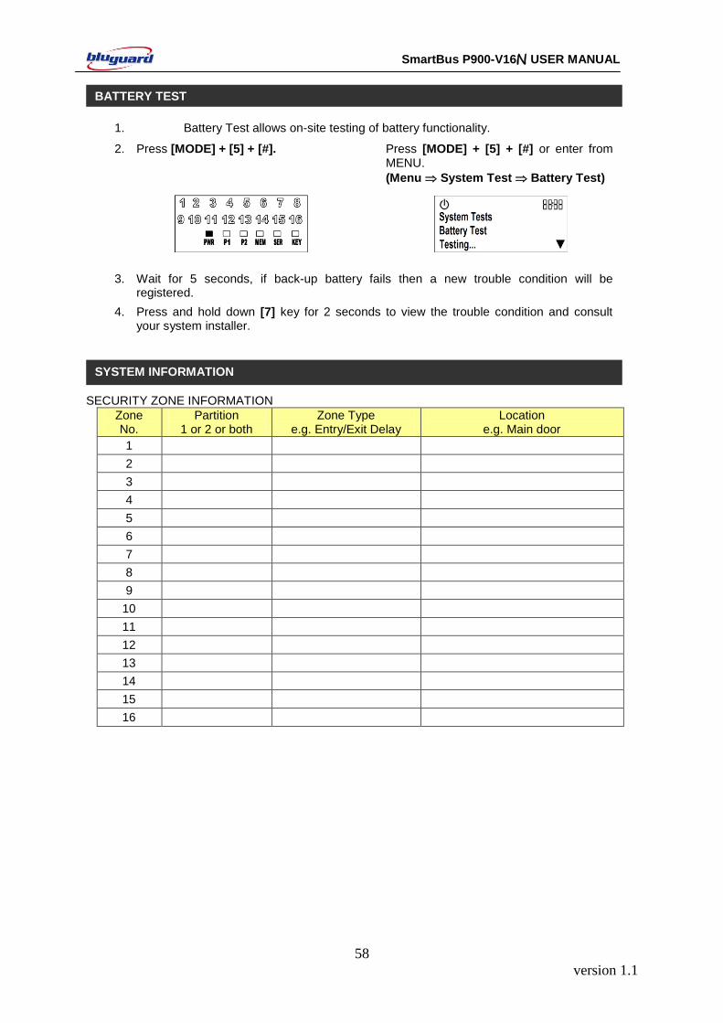
version 1.1
58
SmartBus P900-V16N USER MANUAL
1. Battery Test allows on-site testing of battery functionality.
2. Press [MODE] + [5] + [#]. Press [MODE] + [5] + [#] or enter from MENU.
(Menu System Test Battery Test)
3. Wait for 5 seconds, if back-up battery fails then a new trouble condition will be registered.
4. Press and hold down [7] key for 2 seconds to view the trouble condition and consult your system installer.
SECURITY ZONE INFORMATION
Zone No.
Partition 1 or 2 or both
Zone Type e.g. Entry/Exit Delay
Location e.g. Main door
1
2
3
4
5
6
7
8
9
10
11
12
13
14
15
16
BATTERY TEST
SYSTEM INFORMATION
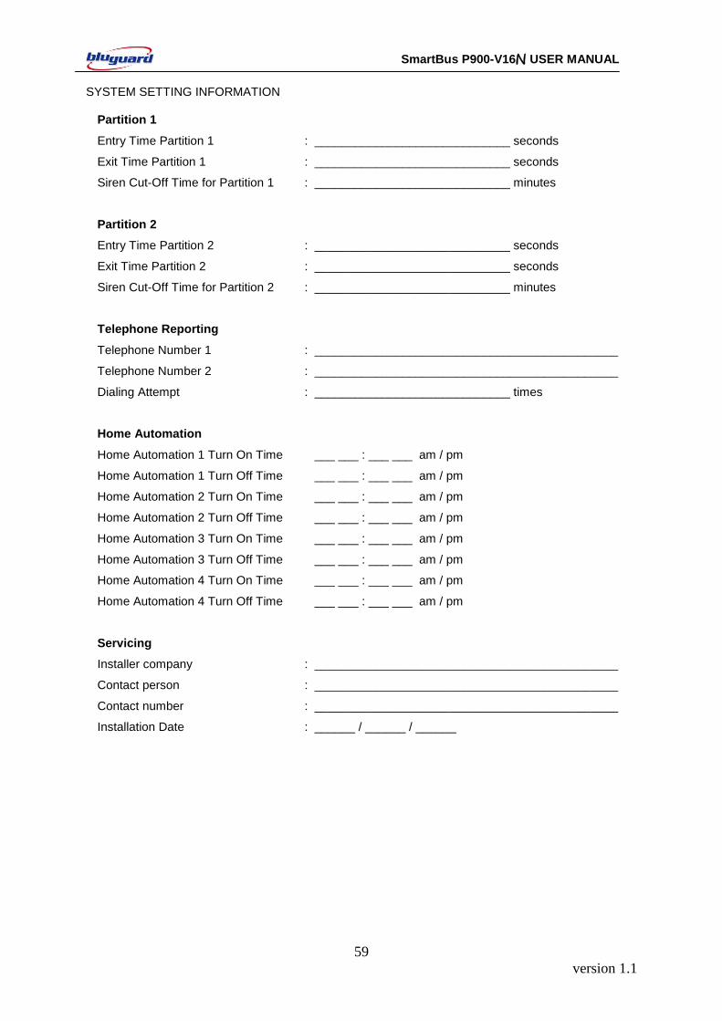
version 1.1
59
SmartBus P900-V16N USER MANUAL
SYSTEM SETTING INFORMATION
Partition 1
Entry Time Partition 1 : _____________________________ seconds
Exit Time Partition 1 : _____________________________ seconds
Siren Cut-Off Time for Partition 1 : _____________________________ minutes
Partition 2
Entry Time Partition 2 : _____________________________ seconds
Exit Time Partition 2 : _____________________________ seconds
Siren Cut-Off Time for Partition 2 : _____________________________ minutes
Telephone Reporting
Telephone Number 1 : _____________________________________________
Telephone Number 2 : _____________________________________________
Dialing Attempt : _____________________________ times
Home Automation
Home Automation 1 Turn On Time ___ ___ : ___ ___ am / pm
Home Automation 1 Turn Off Time ___ ___ : ___ ___ am / pm
Home Automation 2 Turn On Time ___ ___ : ___ ___ am / pm
Home Automation 2 Turn Off Time ___ ___ : ___ ___ am / pm
Home Automation 3 Turn On Time ___ ___ : ___ ___ am / pm
Home Automation 3 Turn Off Time ___ ___ : ___ ___ am / pm
Home Automation 4 Turn On Time ___ ___ : ___ ___ am / pm
Home Automation 4 Turn Off Time ___ ___ : ___ ___ am / pm
Servicing
Installer company : _____________________________________________
Contact person : _____________________________________________
Contact number : _____________________________________________
Installation Date : ______ / ______ / ______