smartascreen Gate Miniscreen Installation Guide Fence... · LYSAGHT fence and gate Installation...
28
LYSAGHT fence and gate Installation Guide NEETASCREEN® SMARTASCREEN® MINISCREEN® CUSTOMSCREEN® Selection guide for non-cyclonic regions with detailed installation instructions given for assembly of fences, gates and lattices range of COLORBOND® steel colours lattices
Transcript of smartascreen Gate Miniscreen Installation Guide Fence... · LYSAGHT fence and gate Installation...

LYSAGHT fence and gate
Installation Guide
NEETASCREEN®
SMARTASCREEN®
MINISCREEN®
CUSTOMSCREEN®
Selection guide for non-cyclonic regions
with detailed installation instructions given
for assembly of fences, gates and lattices
range of COLORBOND® steel colours
lattices

Table of contents
1. Introducing LYSAGHT fencing .............................
2. Components for fence assembly and installation ...............................................................4
...............................................................5
4. Fence selection ......................................................6
5. Select fence posts and caps ...............................7
6. Determine post lengths .........................................8
7. Footings ...................................................................9
8. Installing a fence: step by step ..........................10
9. Installing fence posts ..........................................11
10. Preparing raked sections .................................12
11. Installing infill sheets.........................................
12. Finishing off the fence installation ..................14
.......................................15
14. Tapering ends of fences ...................................15
15. Installing infill strips & post caps ....................16
16. Gate sizes, gate combinations and gate kits .17
17. Components for gate assembly and
installation ..........................................................18
18. Installation of gate posts and gates ...............19
19. Gate assembly - preparation steps (NEETASCREEN, SMARTASCREEN and CUSTOMSCREEN gates) ...................................20
20. Gate assembly (NEETASCREEN, SMARTASCREEN & CUSTOMSCREEN gates)21
21.Gate assembly - preparation steps (MINISCREEN gates) ..........................................
22.Gate assembly (MINISCREEN gates) ..............24
LYSAGHT fence ....................................................................26
24. Post caps installation ........................................27
2
1. Introducing LYSAGHT fencing
Not all fences made from COLORBOND® steel are created equal. LYSAGHT® fences are stylish, strong, economical and durable.
LYSAGHT fencing is a quality product because we offer a strong, cleverly-designed post. Greater depth of the rail means there is a lot more latitude when raking fences. Designed to Australian wind loading standards, LYSAGHT fences and gates are available in standard heights of 1500, 1800 & 2100mm and a selected range of of pre-painted COLORBOND® steel fence colours. These fences can be installed on flat and sloping grounds, and are complemented by many accessories, including a range of matching gates. They may be installed all over Australia
AS/NZS 1170.2: 2002 Structural Design Loads, Part 2: Wind Loads (See map Figure 4.2). Refer to our cyclonic fencing range for use these areas. Environment Our fences have good resistance to accidental spillage of solvents, however they should not be installed within one kilometre of marine, severe industrial or other corrosive environments. Both freshwater and saltwater swimming pools contain corrosive chemicals, and your warranty does not cover fences or gates if they get splashed with the contents of swimming pools. Fences and gates must be installed clear of the ground. This is a step-by-step guide for the selection and installation of LYSAGHT NEETASCREEN®, SMARTASCREEN®, CUSTOMSCREEN® and MINISCREEN® steel fences and their matching gates. When these fences are topped with attractive steel lattice or slats and decorative ball caps, they are called NEETASCREEN PLUS®, SMARTASCREEN PLUS® CUSTOMSCREEN PLUS® and MINISCREEN PLUS®. There are
The LYSAGHT Fence Warranty* When you buy your steel fence from BlueScope Lysaght you can be assured you are getting a 100% Australian made product backed by the strength and reputation of one of
Your purchase of a LYSAGHT® steel fence gives you the protection of two unique warranties for your peace of mind. 1. Your LYSAGHT® 10 Year Fencing Warranty covers the
guarantee that your fence will remain standing for years to come*; and 2. A separate COLORBOND® steel warranty covers the material used to manufacture your LYSAGHT® modular fence system against corrosion to perforation by weathering in the natural elements, and against paint flake and peel. For further information on the warranties available for a LYSAGHT® fence and eligibility, visit www.lysaght.com/ warranty.
*This LYSAGHT® 10 Year Fence Warranty replaces the LYSAGHT® 10 Year Complete Fence Warranty from 1 April 2010
For well over 150 years we have consistently manufactured the highest quality building products – and LYSAGHT NEETASCREEN, SMARTASCREEN, CUSTOMSCREEN and MINISCREEN
3

2. Components for fence assembly and installation
Detailed below is the componentry required for assembly and installation of your new fence panels. Ensure you determine the best option and required components from the following pages prior to placing your order. CUSTOMSCREEN® components are available in SA and Qld only. Find gate
components in the Gates section of this manual. Please check with your nearest sales centre for availability of components in your area.
LYSAGHT post capail pr To
Infill sheet (NEETASCREEN shown)
Optional Ball cap
Top lrai e ailtic
Lat top r er Low
Infill sheet (NEETASCREEN shown)
l LYSAGHTrai post cap Top
Infill sheet
Centre rail
Optional Ball cap Top
rai l e ailticrLat r top e Low
Infill sheet
Centre rail
B NEETASCREEN SMARTASCREEN & CUSTOMSCREEN
Posts Posts Posts Posts
om ott
ra il
B NEETASCREEN PLUS SMARTASCREEN PLUS & CUSTOMSCREEN PLUS
ail mr oott
mtto Bo
rai l
tBo MINISCREEN PLUS
r tom
ail
MINISCREEN
Rails
60
53
NEETASCREEN & SMARTASCREEN universal rail 60
48
CUSTOMSCREEN universal rail
300 nominal 300 nominal
Infill sheets Standard lengths 1490, 1790 & 2090 mm Standard lengths for ‘Plus’ 1190, 1490 & 1790 mm
2350mm 60
38 2350mm MINISCREEN
NEETASCREEN range range
SMARTASCREEN
universal rail
2370mm
2350mm
MINISCREEN
29 28
centre rail CUSTOMSCREEN range
range
6
MINISCREEN
Lattice infill
Slats infill (Available NSW, Vic., W.A. only)
16
‘Plus’ Options Standard length 2350 mm NEETASCREEN PLUS SMARTASCREEN PLUS MINISCREEN PLUS Standard length 2370 mm CUSTOMSCREEN PLUS
Lysaght Posts Standard lengths 2100, 2400, 2700 & 3000 mm 84
43
Post caps Fasteners
LYSAGHT post cap
(cut with knife to get single caps)
(All fence types)
60 x 60 x 1.6 65 x 65 x 2.5 Standard lengths 2400, 3000
Standard length 2400 mm
(Fence Types 2 & 3)
Self-drilling, self tapping hex. washer-head screws 10—16 x 16
(Fence Type 3 only) (Fence Types 2 & 3)
Ripple screws (MINISCREEN range only)
RippleZip® screw or M4.8—16 x 25
Square (tubular) post cap (for square post) 60 x 60, 65 x 65
Optional Ball cap
Self-drilling, self tapping, long drill bit hex. head screw 12—24 x 32
Self-drilling, self tapping, hex. head screw 12—14 x 45 or RoofZips M6-11x50 or AutoTeks M5.5-14x50
Ripple Tek® screw 10—16 x 20
4
1200 Standard post
Square (tubular) post
Post cover strip
Standard post stiffener
3. At the start
Before you order
components in order to get the fence you want. This includes choosing the right fence type, post lengths and infill profile. NEETASCREEN, NEETASCREEN PLUS; SMARTASCREEN, SMARTASCREEN PLUS; CUSTOMSCREEN, CUSTOMSCREEN PLUS; MINISCREEN or MINISCREEN PLUS.
Standard components A standard Type 1 fence panel consists of the following components: NEETASCREEN, SMARTASCREEN and CUSTOMSCREEN components 2 Standard posts 2 NEETASCREEN, SMARTASCREEN or CUSTOMSCREEN universal rails NEETASCREEN, SMARTASCREEN or CUSTOMSCREEN infill sheets 1 LYSAGHT post cap*
NEETASCREEN PLUS, SMARTASCREEN PLUS and CUSTOMSCREEN PLUS components 2 Standard posts NEETASCREEN, SMARTASCREEN or CUSTOMSCREEN universal rails NEETASCREEN, SMARTASCREEN or CUSTOMSCREEN infill sheets 1 Lattice 1 Ball cap*
2 Post infill strips (optional) MINISCREEN components 2 Standard posts 2 MINISCREEN universal rails 1 Centre rail MINISCREEN infill sheets 1 LYSAGHT post cap*
Before you start work
fence you are installing.
electricity, telephone, gas or water mains.
Tools you need
LYSAGHT post caps) 7 Ripple Tek® or RippleZip® screws
MINISCREEN plus components 2 Standard posts MINISCREEN universal rails 1 Centre rail MINISCREEN infill sheets 1 Lattice 1 Ball cap*
7 Ripple Tek® or RippleZip® screws 2 Post infill strips (optional)
configurations (Page 7).
required)
Components
Posts and post caps Each standard fence panel is supplied with two standard posts. However, depending on how you configure corners and
some square posts (Figure 5.1).
type of additional post caps. NOTE: Gates are dealt with seperately at the back of this manual.
fences contain the addition of a post stiffener and are limited to only two infill sheets and have added fasteners to stitch the rails to the infill sheets. Cyclonic fences are detailed NEETASCREEN NEETALOK
5
4. Fence selection
a quality product that will enhance the appearance of your home
can add style and value while providing privacy and security. It is important to make your fence selection based on both your aesthetic requirements, but also the suitability to the environment your fence is to be erected. Ensure you get a long lasting, value adding boundary fence by following the guidelines below: Installation environment Steel fences should not be installed within 1 km of marine, severe
the fence is near a swimming pool because pool water splashed on the fence will void the warranty. The fence must be installed clear of the ground to ensure longevity. These fences are not to be used as a retaining wall. 1. Determine your wind region The information in this guide is suitable for use only in regions A and B of AS/NZS 1170.2: 2002 Structural Design Loads, Part 2: Wind Loads (Figure 4.2). Cyclonic regions are covered in our cyclonic fence guide. If you have any doubt about the region your fence will be in, get advice from your local building consent authority. 2. Determine your terrain category Select the terrain category that best describes the area in which your fence will be erected from the categories listed below. Use this information to determine the type of fence required
an escarpment, on a ridge, or in terrain category 1, you need engineering advice beyond the scope of this publication. Category 2 Open terrain including sea coast areas, airfields, grassland with a few well-scattered obstructions, such as isolated trees and uncut grass, having heights generally from 1.5 to 10m, and water surfaces. Typically acreage-suburbia with less than 10 houses per hectare. Category 2.5
agricultural land, canefields or long grass to 0.6 m). This category is typical of developing outer urban areas. Less than 10 houses per hectare; or more than 10 houses per hectare, 500 m apart and in two rows. Category 3 Terrain with numerous closely spaced obstructions the size of
ten or more houses per hectare. Hill sides and exposed situations If your fence is situated on the
location, we recommend you 30º
Region A Region B Cyclonic regions
30º
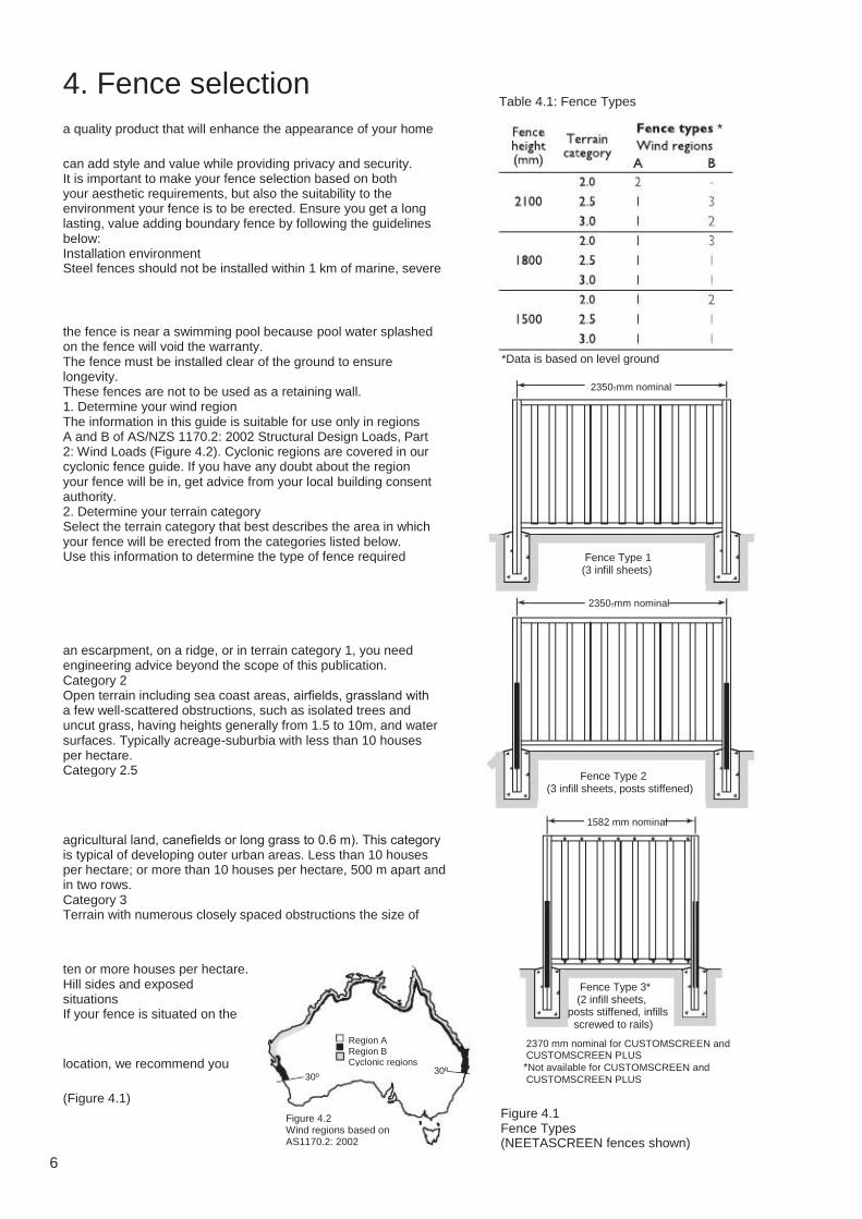
Table 4.1: Fence Types
*
*Data is based on level ground
2350†mm nominal
Fence Type 1 (3 infill sheets)
2350†mm nominal
Fence Type 2 (3 infill sheets, posts stiffened)
1582 mm nominal
Fence Type 3* (2 infill sheets, posts stiffened, infills screwed to rails)
2370 mm nominal for CUSTOMSCREEN and CUSTOMSCREEN PLUS *Not available for CUSTOMSCREEN and CUSTOMSCREEN PLUS
(Figure 4.1) Figure 4.2 Wind regions based on AS1170.2: 2002
Figure 4.1 Fence Types (NEETASCREEN fences shown)
6

5. Select fence posts & caps
Selection of posts Check the number and type of posts you will need, starting with a sketch of your fence site. Mark on it the type of posts you will need (Figure 5.1). You will need to consider:
Choose your post caps based on your post configurations and personal preference. LYSAGHT Post Caps fit two standard LYSAGHT posts screwed back-to-back. For a single standard post, it is easy to cut a cap in half with a sharp knife in the groove moulded into the underside—trim the edges straight. There is a wide range of decorative spears, available from fence retailers and hardware stores, that you can fit to these caps to customise your fence. There are grooves moulded under the cap to help locate fasteners. Ball caps are often used for NEETASCREEN PLUS, SMARTASCREEN PLUS, CUSTOMSCREEN PLUS and MINISCREEN PLUS fences, but can be used on any LYSAGHT fence. They are designed to fit two standard LYSAGHT posts screwed back-to-back. Square post caps suit tubular posts and are usually used at
posts screwed back-to-back);
LYSAGHT posts screwed back-to-back, and this may affect the post configurations you choose. Selection of post caps
touch and to protect against any sharp edges (see Page 16).
Post infill strip
Fence run
TYPICAL POSTS NOT AT A CORNER
R O A D
Intermediate posts Always 2 standard LYSAGHT posts screwed back-to-back 2350
mmnominal
Fence run
Square (tubular) post
TAPERED PANELS Page 15
SKETCH LAYOUT OF FENCE
Gateposts Standard width gates: 60 x 60 x 1.6 Extra wide gates: 65 x 65 x 2.5
TYPICAL CORNERS
Fence run
Fence run
Fence run
Fence run
Fence run
Fence run
Post infill strip
Figure 5.1 Preliminary selection of posts
7

6. Determine post lengths
Height of step (D)
Stepped fence Level fence Raked fence on sloping ground Tapered end
Figure 6.1 Fence installations
If the ground is not all level, consider whether the fence will be stepped or raked (Figure 6.1). For aesthetic reasons, people often choose to step rather than to rake when using a lattice. Fences may be installed raked on slopes of 1 in 20 (117mm NEETASCREEN and SMARTASCREEN, 1 in 25 CUSTOMSCREEN MINISCREEN without cutting components to fit. For steeper slopes you will need to:
Where: A = Height of infill sheet (Figure 6.2) B = 50mm ground clearance (Figure 6.2)
D = If a stepped installation: height of the step (Figure 6.1) Select standard lengths Use the table below to select the lengths you need to order.
Post lengths
If some of the ground is level and some sloping, or if the slope varies markedly, you might need posts of different lengths. Determine basic post lengths (Refer to Figure 6.2. For data on tapered ends, see Page 15). Basic post length = (Footing depth – 40) + (Height above ground) Get the footing depth from Page 9, and height above ground from: Height of post above ground = A + B + C + D
.2
C = 300mm for lattice
2350mm nominal (2370mm nominal for CUSTOMSCREEN & CUSTOMSCREEN PLUS)
(Nominal fence height – 10mm) (Nominal fence
height – 310mm)
Nominal fence height A = Height
of infill A = Height of infill
E = End of post to bottom of concrete 40mm min. 150mm max.
Ground level Footing diameter
Figure 6.2 Panel arrangement (NEETASCREEN shown)
8
Footing depth
B = 50mm nominal ground clearance
1500, 1800 or 2100mm
7. Footings
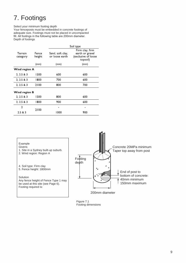
Select your minimum footing depth Your fenceposts must be embedded in concrete footings of adequate size. Footings must not be placed in uncompacted fill. All footings in the following table are 200mm diameter. Depth of footings
Example Givens 1. Site in a Sydney built-up suburb. 2. Wind region: Region A
Concrete 20MPa minimum Taper top away from post
Footing depth
4. Soil type: Firm clay 5. Fence height: 1800mm
Solution Any fence height of Fence Type 1 may be used at this site (see Page 6). Footing required is:
End of post to bottom of concrete: 40mm minimum 150mm maximum
200mm diameter
Figure 7.1 Footing dimensions
9
8. Installing a fence: step by step
So far we have talked about selecting your fence. The following section discusses step by step, how to prepare and install your LYSAGHT fence.
What kind of site do you have? Work out your levels. Is it one straight run, or are there raked or stepped sections?
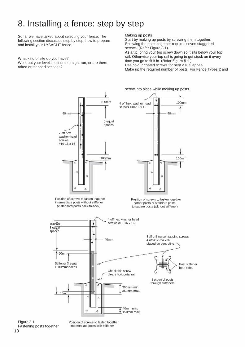
Making up posts Start by making up posts by screwing them together. Screwing the posts together requires seven staggered screws. (Refer Figure 8.1). As a tip, bring your top screw down so it sits below your top rail. Otherwise your top rail is going to get stuck on it every time you go to fit it in. (Refer Figure 8.1.) Use colour coated screws for best visual appeal. Make up the required number of posts. For Fence Types 2 and
screw into place while making up posts.
100mm
40mm
5 equal spaces
100mm
40mm
4 off hex. washer head screws #10-16 x 16
7 off hex. washer-head screws #10-16 x 16
100mm 100mm
Position of screws to fasten together intermediate posts without stiffener (2 standard posts back-to-back)
Position of screws to fasten together corner posts or standard posts to square posts (without stiffener)
4 off hex. washer head screws #10-16 x 16
100mm 3 equal spaces
40mm Self drilling self tapping screws 4 off #12–24 x 32 placed on centreline
50mm
Stiffener 1200mm
3 equal spaces
Post stiffener both sides
Section of posts through stiffeners
300mm min. 350mm max.
Check this screw clears horizontal rail
50mm
40mm min. 150mm max.
Figure 8.1 Fastening posts together
Position of screws to fasten together intermediate posts with stiffener
10

9. Installing fence posts
Gate width plus clearance (See LYSAGHT fence gates assembly & installation instructions at the back of this manual)
Posts set on inside of stringlines
Peg
Stringline
Peg
Stringline
Second post Spirit level
Square post for gate
Gate (usually opens inwards) Figure 9.1 Stringline layout
1. Layout stringlines to position your fence Stringlines mark the outside line of your fenceposts (Figure 9.1), and help to set your fenceposts at a uniform height.
stringline. Keep the stringline taut and set at the top of two end posts. Place the stakes 500mm beyond the corners of the fence, so as not to obstruct the holes. 2. Layout posts and dig holes Mark the position of fenceposts. Lay the rails on the ground butting end to end between the two end posts so you can see
longer rails may need to be used. Refer to the raked section on page 12. If there is to be a gate, locate the gate posts as detailed in LYSAGHT Fence gates assembly and installation guide at the back of this manual. A fence panel can be reduced from the nominal width, without cutting infill sheets, by the increments shown in Figure 12.2. Rails and lattices must be cut to suit a narrow fence panel. Dig the holes using the hole sizes determined from Page 9. 3. Place the first post If the ground slopes, start at the high end. Lay a minimum of 40mm concrete under the end of the post and set your post into the hole. This should be done for every post. Fill the hole with concrete and use your spirit level to get the post plumb. Tamp the concrete down. Ensure that the concrete tapers away from the post. (Figure 7.1).
ground.
4. Place remaining posts Place the second post in its hole and engage a bottom rail with the first and second post. Make sure the bottom rail is 50mm above the ground.
into or out of your post. This helps prevent scratching.
from both sides of each post. Use the stringline to ensure your posts are all the correct height, plumb and in line, before concreting into position. Wait at least 24 hours for the concrete to dry before installing infill sheets. Continue installation of posts and bottom rails for the remainder of the run.
First post
Mixing your concrete
H
Bottom rail
20 mm blue metal; 2.5 parts sand; 1 part cement. Add
Ground level 50mm nominal concrete (20MPa min.)
may also be used.
Figure 9.2 Placing remaining posts
Use stringline to set post heights. Lay the rails along the string line to determine positions of posts.
Set all the bottom rails into position ensuring a 50mm ground clearance.
11

10. Preparing raked sections
If your fence requires raked sections, you may need to prepare the rails and infill sheets. If your fence is level or stepped, skip ahead to the infill installation instructions. Preparing rails For small rakes, the increase in the length of top and bottom
Fence Types 1 & 2*
The length to cut these raked sections is detailed in the table at right, once you have determined the height of the cut.
Trim top and bottom of infill sheets
Fencepost d
Fence Type 3
* For CUSTOMSCREEN, 2370mm is the normal rail length and add 20mm to angled rail length shown.
Fencepost
d = D / (number of infill sheets)
Figure 10.1 Cutting infill sheets for a raked fence (Fence types 1 and 2 shown)
Preparing infill sheets Work out the measure of the cut by resting your spirit level inside the rail (at least the width of a sheet) at the high end of the rail (Refer photo). Measure the width of a sheet, and measure the distance with your tape between the bottom of the level and the inside of the rail. That will show you the angle of your cut. Wherever possible, make the rake on the bottom rail the same as the top. Measure the height of your fence up from your cut edge and cut at the same angle at the top of the sheet.
to mark the cut, as a pencil may cause corrosion. Fine tune rails before screwing them into position. Ensuring the rails are aligned, and the sheets are neat vastly improves the appearance of your fence. Once you have installed all the bays, stand back from the fence and have a look at the fence as a whole. Make sure the lines on your sheets run
of the overlap looks flush, without a big
Screw the rails into position. Remove any swarf from the installation.
Measure the amount to be cut and mark the sheet. Ensure you measure edge to edge, not rib to rib.
Cut the infill sheets three at a time. This equals a single bay and ensures uniformity. Measure twice, cut once.
Measure the fall on the rail. This will allow you to position the top rail parallel and also to correctly cut the infill sheets.
12

11. Installing infill sheets
Installing the infill sheets is where the art is in fencing. It requires getting a few
preferable to treat this as a one person
The following steps assume a standard fence style, however the steps are
For the installation of the lattice for a
Start at the high side. Insert the first sheet flush into the bottom rail, usually about 200mm out from the post. Lift the top rail and slowly slide the sheet into the top rail. Using your knee near the bottom of the sheet and your hand near the top, slowly ease the first sheet along the rails until they contact the post. Remember to move the sheet square or it might kick out of one of the rails. When the second infill sheet is placed, make sure you place the sheet to allow for the overlap (Figure 12.2). At this
necessary to get the lap to sit correctly or to fit the sheet into the rail. Gently bump the fence sheet into position as required. The third sheet is the most difficult, only because there are a few things to get right. Place the bottom of the sheet into the rail, ensuring there is overlap to the second sheet. It is usually necessary to gently bump, and push this final sheet into position. Roll the top rail away from you and this will assist feeding the top of the sheet into the rail channel. Get the side facing away from you in the bottom rail and then you can push the ridges of the side facing towards you into position with both the rail and the post. Once the sheet is in position, gently tap the top rail down onto the sheets using the heel of your gloved hand. Do not screw off the top rail until you
back and looking at the whole of the fence. This allows you to make minor
Lift top rail and place 1st sheet into bottom rail. Slide to end position.
Lifting top rail helps ease 1st sheet into end position.
Place 2nd sheet into bottom rail, ensuring there is sufficient overlap.
used. Lift top rail and rotate until infill sheet slides into rail. Tap top rail down into position.
13
12. Finishing off the fence installation
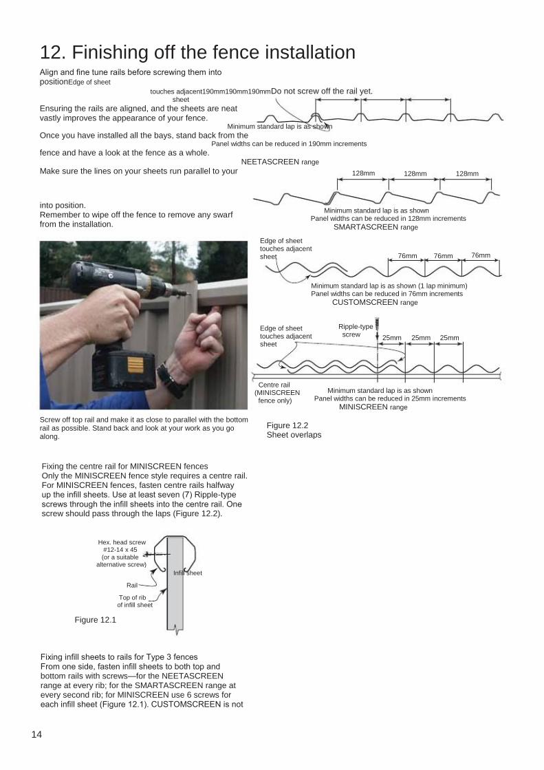
Align and fine tune rails before screwing them into positionEdge of sheet touches adjacent190mm190mm190mmDo not screw off the rail yet. sheet Ensuring the rails are aligned, and the sheets are neat vastly improves the appearance of your fence. Minimum standard lap is as shown Once you have installed all the bays, stand back from the Panel widths can be reduced in 190mm increments fence and have a look at the fence as a whole. NEETASCREEN range Make sure the lines on your sheets run parallel to your 128mm 128mm 128mm
into position. Remember to wipe off the fence to remove any swarf from the installation.
Minimum standard lap is as shown Panel widths can be reduced in 128mm increments SMARTASCREEN range
Edge of sheet touches adjacent sheet 76mm 76mm 76mm
Minimum standard lap is as shown (1 lap minimum) Panel widths can be reduced in 76mm increments CUSTOMSCREEN range
Edge of sheet touches adjacent sheet
Ripple-type screw
25mm 25mm 25mm
Centre rail (MINISCREEN fence only)
Minimum standard lap is as shown Panel widths can be reduced in 25mm increments MINISCREEN range
Screw off top rail and make it as close to parallel with the bottom rail as possible. Stand back and look at your work as you go along.
Figure 12.2 Sheet overlaps
Fixing the centre rail for MINISCREEN fences Only the MINISCREEN fence style requires a centre rail. For MINISCREEN fences, fasten centre rails halfway up the infill sheets. Use at least seven (7) Ripple-type screws through the infill sheets into the centre rail. One screw should pass through the laps (Figure 12.2).
Hex. head screw #12-14 x 45 (or a suitable alternative screw)
Rail Top of rib of infill sheet
Figure 12.1
Fixing infill sheets to rails for Type 3 fences From one side, fasten infill sheets to both top and bottom rails with screws—for the NEETASCREEN range at every rib; for the SMARTASCREEN range at every second rib; for MINISCREEN use 6 screws for each infill sheet (Figure 12.1). CUSTOMSCREEN is not
14
Infill sheet

13. Installing ‘Plus’ option
Inserting the lattice or slats Engage a top rail onto the top of a
2
3 hex. head screws #10-16 x 16
orientation). Lower the rail and lattice or slats onto the top of a fence panel, engaging the ends of the rail with the posts (Figure
1
25mm
along the bottom flange of the lattice or
with a piece of cardboard between the drill and the lattice.
Figure 13.1 1 Rail installation at top of infill panel 2 Installation of lattice
3 hex. head screws #10-16 x 16
25mm
Fasten the top rail to the posts with one
sides of each post. A component (Edge cover strips used for gates) is available to cover edges of the lattice or slats if it is trimmed in length or use flashing/trim as described in gates.
Figure 13.2 Fastening of lattice (NEETASCREEN rails shown)
14. Tapering ends of fences
At the end of a fence run, where the
called a free end), the panels Full height of fence (H)
Top rail len gth
For 2100mm high fences fix tapered infill panels to top and bottom rails as as shown in Figure 12.1. Top rail length
Height of middle post
region B and all of wind region A. In all other cases your fence must be tapered in height over the last two panels (Figure 14.1). Cut the top of the infill sheets in a manner similar to that shown for a raked fence (Figure 14.1).
Normal rail length Normal rail length
*
* 2370 mm normal rail length for CUSTOMSCREEN Add 20mm to top rail length shown for CUSTOMSCREEN
Figure 14.1 Tapering ends of fences over two panels
H/2 beyond the alignment of your house. Tapering of 1500mm high fences is not
15
15. Installing infill strips & post caps
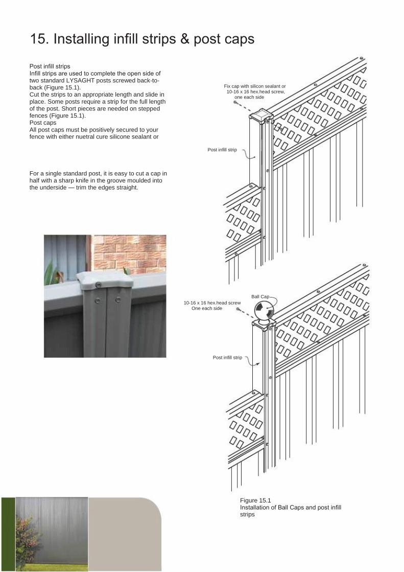
Post infill strips Infill strips are used to complete the open side of two standard LYSAGHT posts screwed back-to- back (Figure 15.1). Cut the strips to an appropriate length and slide in place. Some posts require a strip for the full length of the post. Short pieces are needed on stepped fences (Figure 15.1). Post caps All post caps must be positively secured to your fence with either nuetral cure silicone sealant or
For a single standard post, it is easy to cut a cap in half with a sharp knife in the groove moulded into the underside — trim the edges straight.
Fix cap with silicon sealant or 10-16 x 16 hex.head screw, one each side
Post infill strip
Ball Cap 10-16 x 16 hex.head screw One each side
Post infill strip
Figure 15.1 Installation of Ball Caps and post infill strips
16
16. Gate sizes, gate combinations and gate kits
There are a large range of gate sizes, gate combinations and gate accessories available. To simplify the selection of the components to make up the gate system, there are a range of kits available. Our gate systems are designed to perfectly complement our fence styles. Detailed instructions for the assembly of the gate system with line drawings are given, together with a set of pictorial instructions. Please refer to both to help you visualise the process. Because MINISCREEN gates are assembled slightly differently, they are dealt with in a separate section to the NEETASCREEN, SMARTASCREEN and CUSTOMSCREEN gates. All gates are all fast and easy to install. Tools required
assembly and installation. With particular application to the gate assembly and installation the tools required are; screw gun, tin snips, safety gloves and glasses, marker and tape measure, fine toothed metal file and square. Gate widths, gate post spacing and footings For gate widths and post clearances see Table 16.2 below. For single gates, posts clearance must be the width of the gate, plus 20mm (i.e. 10mm post/gate clearance on either side). For double gates, posts clearance must be the width of the double
and 10mm gate/gate clearance).
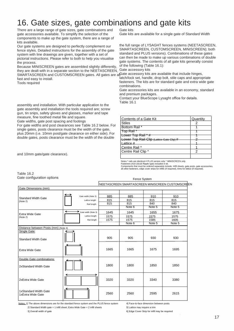
Gate kits Gate kits are available for a single gate of Standard Width
the full range of LYSAGHT fences systems (NEETASCREEN, SMARTASCREEN, CUSTOMSCREEN, MINISCREEN); both standard and PLUS versions). Combinations of these gates can then be made to make up various combinations of double gate systems. The contents of all gate kits generally consist of the following (Table 16.1): Gate accessory kits Gate accessory kits are available that include hinges, latch/lock set, handle, drop bolt, stile caps and appropriate fasteners. The kits are for standard gate and extra wide gate combinations. Gate accessories kits are available in an economy, standard and premium packages. Contact your BlueScope Lysaght office for details. Table 16.1
Contents of a Gate Kit Stiles Bottom Rail * Top Rail * Lower Top Rail * # Lower Top Rail Clip (Lattice Gate Clip) # Lattice # Centre Rail ^ Centre Rail Clip ^
Quantity 2 1 1 1 2 1 1 2
Notes * rails are identical # PLUS version only ^ MINISCREEN only Fasteners (#10-16x16 Ripple type) included in kit. Components that must be ordered separately include: Infill sheets, gate posts, gate accessories, all other fasteners, edge cover strips for infills (if required), trims for lattice (if required).
Table 16.2 Gate configuration options
Gate Dimensions (mm)
Standard Width Gate (Note 2)
Gate width (Note 3) Lattice length
Rail length
Fence System NEETASCREEN SMARTASCREEN MINISCREEN CUSTOMSCREEN
885 815 815
885 815 815 Note 6
910 815 840 Note 5
910 815 840 Note 5
Extra Wide Gate (Note 2)
Gate width (Note 3) Lattice length
Rail length
1645 1575 1575
1645 1575 1575 Note 6
1655 1575 1585 Note 5
1675 1575 1605 Note 5
Distance between Posts (mm) (Note 4) Single Gate:
Standard Width Gate
Extra Wide Gate
Double Gate combinations:
2xStandard Width Gate
905
1665
905
1665
930
1675
930
1695
1800 1800 1850 1850
2xExtra Wide Gate 3320 3320 3340 3380
1xStandard Width Gate 1xExtra Wide Gate 2560 2560 2595 2615
Notes: 1] The above dimensions are for the standard fence system and the PLUS fence system 2] Standard Width gate = 1 infill sheet; Extra Wide Gate = 2 infill sheets 3] Overall width of gate
4] Face-to-face dimension between posts 5] Lattice may require a trim 6] Edge Cover Strip for infill may be required
17

17. Components for gate assembly and installation
Detailed below is the componentry required for assembly and installation of your new fence gate. Ensure you determine the best option and required components from the following pages prior to placing your order. NOTE: CUSTOMSCREEN® components are available in SA and Qld only. Please check with your nearest sales centre for availability in your area.
Top rail
Lattice Spigot
Lower top rail Lattice gate clip
Top rail
Lattice Spigot Top rail
Spigot
Lattice gate clip
Centre rail and clip
Stile Infill sheet
Stile Infill sheet
Stile
Top rail
Spigot
Lower top rail Centre rail and clip
Stile Infill sheet
Stile Infill sheet
Stile Stile
Spigot Bottom rail Bottom rail
Spigot Bottom rail
Spigot Bottom rail
Spigot
NEETASCREEN PLUS, SMARTASCREEN PLUS, CUSTOMSCREEN PLUS
NEETASCREEN, SMARTASCREEN, CUSTOMSCREEN
MINISCREEN PLUS MINISCREEN
Infill sheets Standard lengths 1490, 1790 & 2090 mm Standard lengths for ‘Plus’ 1190, 1490 & 1790 mm
CUSTOMSCREEN
NEETASCREEN SMARTASCREEN range
16
MINISCREEN range range
range
6 29
28
Rails
60
53
NEETASCREEN & SMARTASCREEN universal rail
815mm & 1575mm
48
60
840mm & 1605mm
CUSTOMSCREEN universal rail
60
38 840mm & 1585mm MINISCREEN
840mm & 1585mm MINISCREEN
universal rail
L
centre rail
Fasteners ‘Plus’ Options
300 nominal Lattice infill
Ripple screws (MINISCREEN gates only) Edge cover strip
(SMARTASCREEN only) Standard lengths L= 1160, 1460, 1700, 2060
Standard lengths for both Lattice and Slats infills 815mm & 1575mm
300 nominal RippleZip® screw
(Extra Wide gates only) or M4.8—16 x 25 (All gate types)
Self-drilling, self tapping, hex. head screw 12—14 x 45 or RoofZips M6-11x50 or AutoTeks M5.5-14x50
Figure 17.1 Gate components
Ripple Tek® screw 10—16 x 20
Self-drilling, self tapping hex. washer-head screws 10—16 x 16
Slats infill (Available NSW, Vic., W.A. only)
18
Stile
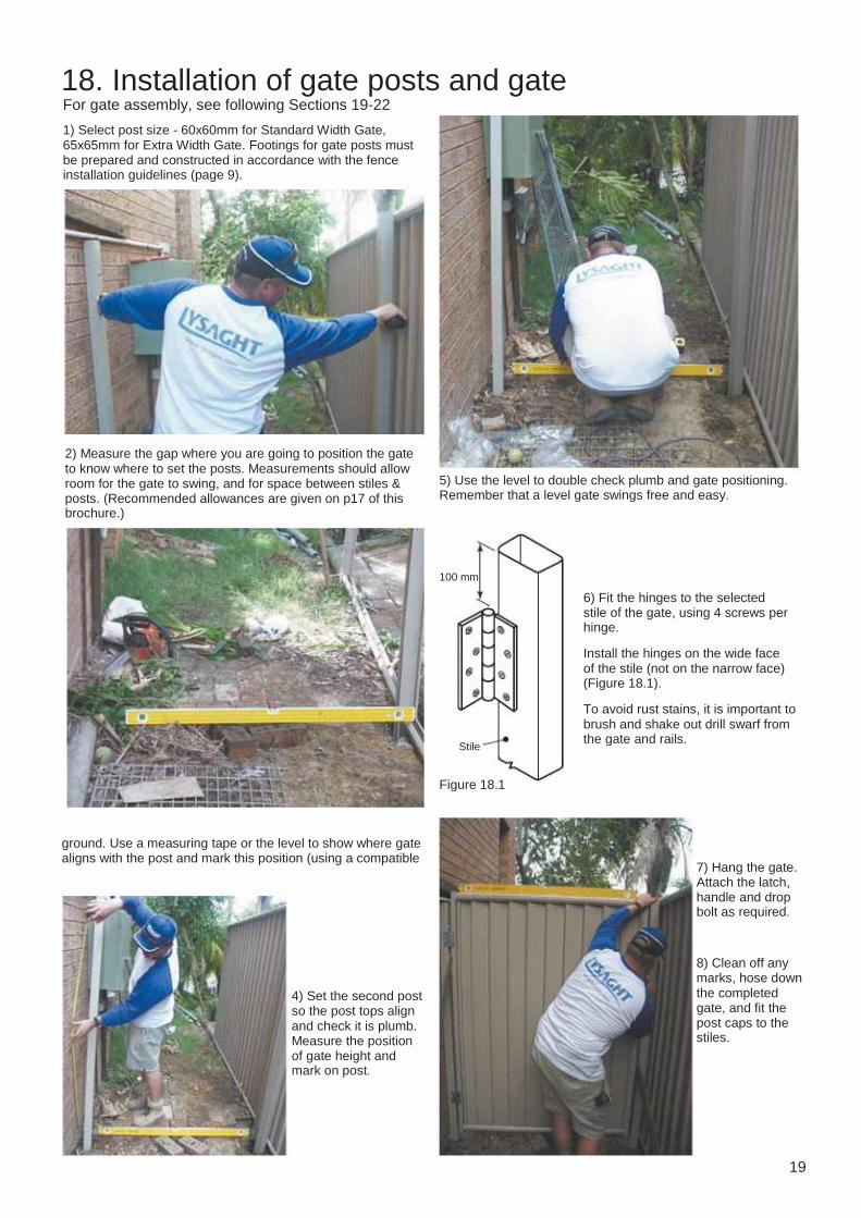
18. Installation of gate posts and gate For gate assembly, see following Sections 19-22
1) Select post size - 60x60mm for Standard Width Gate, 65x65mm for Extra Width Gate. Footings for gate posts must be prepared and constructed in accordance with the fence installation guidelines (page 9).
2) Measure the gap where you are going to position the gate to know where to set the posts. Measurements should allow room for the gate to swing, and for space between stiles & posts. (Recommended allowances are given on p17 of this brochure.)
5) Use the level to double check plumb and gate positioning. Remember that a level gate swings free and easy.
100 mm
6) Fit the hinges to the selected stile of the gate, using 4 screws per hinge.
Install the hinges on the wide face of the stile (not on the narrow face) (Figure 18.1).
To avoid rust stains, it is important to brush and shake out drill swarf from the gate and rails.
Stile
Figure 18.1
ground. Use a measuring tape or the level to show where gate aligns with the post and mark this position (using a compatible
7) Hang the gate. Attach the latch, handle and drop bolt as required.
8) Clean off any marks, hose down the completed gate, and fit the post caps to the stiles.
4) Set the second post so the post tops align and check it is plumb. Measure the position of gate height and mark on post.
19

19. Gate assembly - preparation steps
(NEETASCREEN, SMARTASCREEN & CUSTOMSCREEN gates)
Infill sheet 1) Lay sheet(s) on a horizontal surface. Use some soft material to protect the COLORBOND® steel finish.
Hex. head screw at crest of rib
edges (Figure 19.2). NEETASCREEN GATE
Hex. head screw
4) If required, fit edge cover strip to one side of the infill sheet for SMARTASCREEN gate only. (Figure 19.4)
Gate Lattice or Slats
5) If required, trim the lattice to fit the width of your gate. Equally trim both ends to retain a balanced effect. (Figure 19.6)
6) Notch the top leg of the lattice/slats on both ends. (Figure 19.5)
General
7) Carefully file all cut edges to remove burrs. Edge of sheet touches adjacent sheet
CUSTOMSCREEN GATE
SMARTASCREEN GATE
Hex. head screw
190mm 190mm 190mm
Figure 19.2
Minimum standard lap is as shown Gate widths can be reduced in 190mm increments
NEETASCREEN 5 mm
128mm 128mm 128mm 5 mm
Top of sheet X X
X = 10 mm
X = 35 mm
SMARTASCREEN Edge of sheet touches adjacent sheet 76mm 76mm 76mm
NEETASCREEN PLUS SMARTACREEN PLUS CUSTOMSCREEN PLUS
Minimum standard lap is as shown (1 lap minimum) Gate widths can be reduced in 76mm increments Figure 19.3 10 mm
Bottom of sheet
5 mm 5 mm
Direction of ribs
Minimum standard lap is as shown Gate widths can be reduced in 128mm increments
NEETASCREEN SMARTACREEN CUSTOMSCREEN
10 mm
Figure 19.1
ail pr To
CUSTOMSCREEN Notching of corners
10 mm
Top
ge an fl
Trim to suit gate width
x pro m Ap 5 m
ra il Remove
Standard Length tt Bo
om
Edge cover strip Figure 19.4 Fit Edge Cover Strip (SMARTASCREEN only)
Figure 19.5 Notch at top of lattice
Figure 19.6 Length of lattice
20

20. Gate assembly
(NEETASCREEN, SMARTASCREEN & CUSTOMSCREEN gates)
1. Complete the preparation steps if they are not already done.
2. Lay out all the components (Figure 20.1) on some soft material to protect the COLORBOND® steel finish.
.
corners, at first inner rib (non side-lap rib) of infill sheet from the stile for NEETASCREEN and SMARTASCREEN and
4. For (with lattice/slats) gate:
screws. Mark the position of the two lattice gate clips. Fasten the
16) for each (Figure 20.2).
5. Lay the infill sheet(s) on a horizontal surface. Slide the top rail (lower top rail if lattice is used) onto the top of a sheet(s). A rubber mallet or piece of timber can help.
6. Fit the bottom rail similarly.
7. Insert the spigots of the stiles into the top and bottom rails.
If a lattice is used, ensure that the lower top rail fits neatly
Even up the sheets by bumping the ribs with the palm of your hand.
screws.
Top rail
Gate Lattice
Spigot
Lower top rail Lattice gate clip
Infill sheet Stile
12 mm
Top of sheet
12 mm
Length of sheet measured from inside of spigot
Spigot
Bottom rail Figure 20.1 Initial layout of parts Inner rib alignment
20 mm
Location of lattice gate clip Hex. head screws
Figure 20.2 Positioning of lattice clips for gates with lattice or slats.
Figure 20.3 BEFORE AFTER
Assembly of stiles (NEETASCREEN PLUS shown)
Stile
21
Inner rib alignment = =
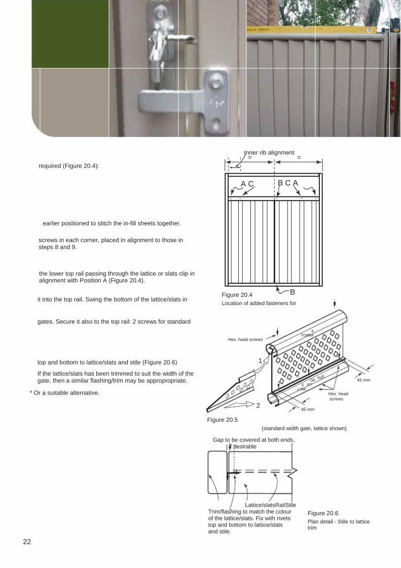
required (Figure 20.4):
A C B C A
earlier positioned to stitch the in-fill sheets together.
screws in each corner, placed in alignment to those in steps 8 and 9.
the lower top rail passing through the lattice or slats clip in alignment with Position A (Figure 20.4).
it into the top rail. Swing the bottom of the lattice/slats in
gates. Secure it also to the top rail: 2 screws for standard
Hex. head screws TOP
IL RA
Figure 20.4 B
Location of added fasteners for
top and bottom to lattice/slats and stile (Figure 20.6)
If the lattice/slats has been trimmed to suit the width of the gate, then a similar flashing/trim may be appropropriate.
* Or a suitable alternative.
1
OP RT
RA IL 45 mm
Hex. head screws
E LOW
2
Figure 20.5
45 mm
(standard width gate, lattice shown)
Gap to be covered at both ends, if desirable
22
Lattice/slatsRailStile Trim/flashing to match the colour of the lattice/slats. Fix with rivets top and bottom to lattice/slats and stile.
Figure 20.6 Plan detail - Stile to lattice trim

21. Gate assembly - preparation steps
(MINISCREEN gates)
Infill sheet 1) Lay sheet(s) on a horizontal surface. Use some soft material to protect the COLORBOND® steel painted finish.
desired width (Figure 21.1). Join the two Gate widths can be reduced in 25mm increments
Minimum standard lap
25mm 25mm 25mm
through the overlaps, at both top and bottom edges (Figure 21.2).
The top and bottom notches are different.
Figure 21.1: Sheet overlaps for extra wide gates
Hex. head screw
Lower top rail and gate lattice
4) If required, trim the lattice to fit the width of your gate. Equally trim both ends to retain a balanced effect. (Figure 21.5) 5) Notch the top leg of the lattice on both ends. (Figure 21.4) 6) Remove the internal lips of the lower top rail for 5 mm at both ends. (Fig. 21.6)
Figure 21.2: Joining of sheets for extra wide gates
5mm
X Top of sheet
5mm
X General
7) File all cut edges to remove burrs.
MINISCREEN: X = 10mm
X = 35mm
Top
xpro Ap mm 5
Remove
eng fla
MINISCREEN PLUS:
10mm Bottom of sheet
5mm 5mm
Direction of ribs
10mm
Figure 21.3: Notching of corners Figure 21.4 Notch at top of lattice
Trim to suit gate width
Standard Length
Figure 21.5: Length of lattice
5m m
Figure 21.6: Notching of lower top rail
23

22. Gate Assembly
1. Complete the preparation steps if they are not already done. 2. Lay out all the components (Figure 22.1) on some soft material to protect the COLORBOND® steel finish.
mark the position of the two lattice gate clips. Fasten the
Top rail
Gate Lattice
Spigot (MINISCREEN gates)
Lower top rail Lattice gate clip
4. Mark the position of the two centre rail clips, with the inner edge of the clip 2mm from the centreline of the
Centre rail & clip
Infill sheet 5. Lay the infill sheet(s) on a horizontal surface. Slide the
of a sheet(s). A rubber mallet or piece of timber can help. 6. Fit the bottom rail similarly. 7. Insert the spigots of both stiles into the top and bottom rails and locate the centre rail on its clips. If a lattice is used, ensure that the lower top rail fits neatly onto the lattice gate clips (Figure 22.2). Even up the sheets by bumping the ribs with the palm of your hand.
Stile
Spigot
Bottom rail
Figure 22.1 Initial layout of parts (showing ‘Plus’ option)
the inside edge of the stile (Figure 22.2).
the four corners, 170mm from the stile (Figure 22.2).
170 mm 20 mm
Location of lattice gate clip
Hex. head screws Top of infill sheet
18mm
18mm
Equal
Location of centre rail clip 2mm
BEFORE AFTER
Figure 22.2 Assembly of stiles (MINISCREEN PLUS shown)
Length of sheet measured from inside to spigot
Equal
Equal Equal
Stile centreline
with lattice without lattice
Figure 22.3 Positioning of clips for gates
24
Stile
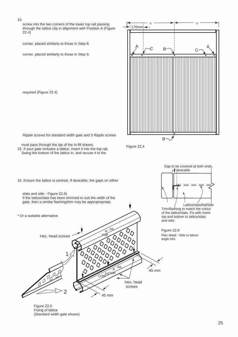
10. screw into the two corners of the lower top rail passing through the lattice clip in alignment with Position A (Figure 22.4)
corner, placed similarly to those in Step 8.
corner, placed similarly to those in Step 9.
170mm = =
A C B C
A
required (Figure 22.4)
Ripple screws for standard width gate and 5 Ripple screws
must pass through the lap of the in-fill sheets. 15. If your gate includes a lattice, insert it into the top rail. Swing the bottom of the lattice in, and secure it to the
Figure 22.4
B
Gap to be covered at both ends, if desirable
16. Ensure the lattice is centred. If desirable, the gaps on either
slats and stile - Figure 22.6) If the lattice/slats has been trimmed to suit the width of the gate, then a similar flashing/trim may be appropropriate.
* Or a suitable alternative.
AIL
Lattice/slatsRailStile Trim/flashing to match the colour of the lattice/slats. Fix with rivets top and bottom to lattice/slats and stile.
Hex. head screws R TOP
Figure 22.6 Plan detail - Stile to lattice angle trim
1
ER R TOP
AIL 45 mm
Hex. head screws
LOW
2
Figure 22.5 Fixing of lattice (Standard width gate shown)
45 mm
25

Screws 23. Adding a ‘Plus Option’ to an existing
LYSAGHT fence
Conversion kit components*
Component
Ball cap Top rail Lattice (or Slats) Fasteners * (per panel)
Quantity
1 1 1 16
Figure 23.1
Post extension Step 1
Step 2
Step 3
for correct orientation). Lower the rail and lattice onto the top of a fence panel,
Figure 23.2
cardboard between the drill and the lattice.
both sides of each post.
Step 4
They can be secured with one screw on either side of the post
Ball cap
Figure 23.3
Hex. head screws
RA IL
Ins ide
RA IL 25 mm
Hex. head screws Figure 23.5
26 25 mm Figure 23.4
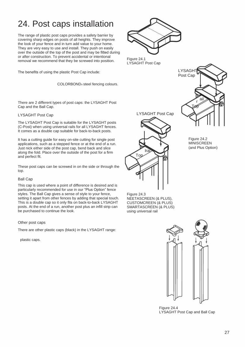
24. Post caps installation
The range of plastic post caps provides a safety barrier by covering sharp edges on posts of all heights. They improve the look of your fence and in turn add value to your home. They are very easy to use and install. They push on easily over the outside of the top of the post and may be fitted during or after construction. To prevent accidental or intentional removal we recommend that they be screwed into position.
The benefits of using the plastic Post Cap include:
COLORBOND® steel fencing colours.
Figure 24.1 LYSAGHT Post Cap
LYSAGHT Post Cap
There are 2 different types of post caps: the LYSAGHT Post Cap and the Ball Cap.
r Top
LYSAGHT Post Cap
ail
LYSAGHT Post Cap
The LYSAGHT Post Cap is suitable for the LYSAGHT posts (C-Post) when using universal rails for all LYSAGHT fences. It comes as a double cap suitable for back-to-back posts.
It has a cutting guide for easy on-site cutting for single post applications, such as a stepped fence or at the end of a run. Just nick either side of the post cap, bend back and slice along the fold. Place over the outside of the post for a firm and perfect fit.
These post caps can be screwed in on the side or through the top.
lrai Top
Figure 24.2 MINISCREEN (and Plus Option)
Ball Cap
This cap is used where a point of difference is desired and is particularly recommended for use in our “Plus Option” fence styles. The Ball Cap gives a sense of style to your fence, setting it apart from other fences by adding that special touch. This is a double cap so it only fits on back-to-back LYSAGHT posts. At the end of a run, another post plus an infill strip can be purchased to continue the look.
Figure 24.3 NEETASCREEN (& PLUS), CUSTOMCREEN (& PLUS) SMARTASCREEN (& PLUS) using universal rail
Other post caps
There are other plastic caps (black) in the LYSAGHT range:
plastic caps.
Figure 24.4 LYSAGHT Post Cap and Ball Cap
27

Disclaimer, warranties and limitation of liability This publication is intended to be an aid for all trades and professionals involved with specifying and installing LYSAGHT products and not to be a substitute for professional
Terms and conditions of sale available at local BlueScope Lysaght sales offices.
Steel Limited will not be under or incur any liability to you for any direct or indirect loss or damage (including, without limitation, consequential loss or damage such as loss of profit or anticipated profit, loss of use, damage to goodwill and loss due to delay) however caused (including, without limitation, breach of contract, negligence and/or breach of statute), which you may suffer or incur in connection with this publication.
© Copyright BlueScope Steel Limited February 22, 2011
Technical enquiries: [email protected] or call 1800 641 417
www.lysaght.com Please check the latest information which is always available on our website.
28MINISCREEN PLUS, CUSTOMSCREEN PLUS and COLORBOND are registered trademarks of BlueScope Steel Limited, LYSAGHT, NEETASCREEN, SMARTASCREEN, MINISCREEN, CUSTOMSCREEN, NEETASCREEN PLUS, SMARTASCREEN PLUS,
LYSAGHT ® range of products is