Smart Wearable Sensors Based on Triboelectric ...
10
micromachines Article Smart Wearable Sensors Based on Triboelectric Nanogenerator for Personal Healthcare Monitoring Ruonan Li 1,2 , Xuelian Wei 3,4 , Jiahui Xu 3,4 , Junhuan Chen 3 , Bin Li 1 , Zhiyi Wu 3,4,5, * and Zhong Lin Wang 3,4,5,6, * Citation: Li, R.; Wei, X.; Xu, J.; Chen, J.; Li, B.; Wu, Z.; Wang, Z.L. Smart Wearable Sensors Based on Triboelectric Nanogenerator for Personal Healthcare Monitoring. Micromachines 2021, 12, 352. https://doi.org/10.3390/mi12040352 Academic Editor: Sang-Jae Kim Received: 8 March 2021 Accepted: 23 March 2021 Published: 25 March 2021 Publisher’s Note: MDPI stays neutral with regard to jurisdictional claims in published maps and institutional affil- iations. Copyright: © 2021 by the authors. Licensee MDPI, Basel, Switzerland. This article is an open access article distributed under the terms and conditions of the Creative Commons Attribution (CC BY) license (https:// creativecommons.org/licenses/by/ 4.0/). 1 School of Chemistry and Chemical Engineering, Guangxi University, Nanning 530004, China; [email protected] (R.L.); [email protected] (B.L.) 2 Center on Nano-Energy Research, School of Physical Science & Technology, Guangxi University, Nanning 530004, China 3 Beijing Institute of Nanoenergy and Nanosystems, Chinese Academy of Sciences, Beijing 100083, China; [email protected] (X.W.); [email protected] (J.X.); [email protected] (J.C.) 4 College of Nanoscience and Technology, University of Chinese Academy of Science, Beijing 100049, China 5 CUSPEA Institute of Technology, Wenzhou 325024, China 6 School of Materials Science and Engineering, Georgia Institute of Technology, Atlanta, GA 30332, USA * Correspondence: [email protected] (Z.W.); [email protected] (Z.L.W.) Abstract: Accurate monitoring of motion and sleep states is critical for human health assessment, especially for a healthy life, early diagnosis of diseases, and medical care. In this work, a smart wearable sensor (SWS) based on a dual-channel triboelectric nanogenerator was presented for a real-time health monitoring system. The SWS can be worn on wrists, ankles, shoes, or other parts of the body and cloth, converting mechanical triggers into electrical output. By analyzing these signals, the SWS can precisely and constantly monitor and distinguish various motion states, including stepping, walking, running, and jumping. Based on the SWS, a fall-down alarm system and a sleep quality assessment system were constructed to provide personal healthcare monitoring and alert family members or doctors via communication devices. It is important for the healthy growth of the young and special patient groups, as well as for the health monitoring and medical care of the elderly and recovered patients. This work aimed to broaden the paths for remote biological movement status analysis and provide diversified perspectives for true-time and long-term health monitoring, simultaneously. Keywords: smart wearable sensor; triboelectric nanogenerator; health monitoring; fall-down alarm system 1. Introduction Wearable devices play a great role in the acquisition and analysis of health informa- tion in recent years. It is an effective method for early detection, early diagnosis, and early treatment of diseases. For example, long-term monitoring of body signs such as electrocardiogram, heart sounds, blood pressure, and pulse is considered in the diagnosis and analysis of cardiovascular diseases [1]. However, the electricity required for wearable devices is mainly generated by traditional electrochemical batteries [2]. They do not only make wearable sensors bulky and uncomfortable to wear, but also requires frequent charg- ing or regular replacement. Wearable energy harvesters, based on different principles, were widely developed, such as electrostatic [3,4], electromagnetic [5–7], thermoelectric [8–10], piezoelectric [11,12], and triboelectric [13,14]. As an energy harvester device, triboelectric nanogenerator (TENG) based on a coupling effect of triboelectrification and electrostatic induction was proved to be very effective to precisely convert mechanical energy (espe- cially low frequency) in the environment into electricity [15–18]. The active sensor based on TENG also showed many advantages, for instance, extremely high sensitivity, strong adaptability, high flexibility, and good environment friendliness [2,19–22]. TENG was Micromachines 2021, 12, 352. https://doi.org/10.3390/mi12040352 https://www.mdpi.com/journal/micromachines
Transcript of Smart Wearable Sensors Based on Triboelectric ...

micromachines
Article
Smart Wearable Sensors Based on Triboelectric Nanogeneratorfor Personal Healthcare Monitoring
Ruonan Li 1,2, Xuelian Wei 3,4, Jiahui Xu 3,4, Junhuan Chen 3, Bin Li 1, Zhiyi Wu 3,4,5,* and Zhong Lin Wang 3,4,5,6,*
�����������������
Citation: Li, R.; Wei, X.; Xu, J.; Chen,
J.; Li, B.; Wu, Z.; Wang, Z.L. Smart
Wearable Sensors Based on
Triboelectric Nanogenerator for
Personal Healthcare Monitoring.
Micromachines 2021, 12, 352.
https://doi.org/10.3390/mi12040352
Academic Editor: Sang-Jae Kim
Received: 8 March 2021
Accepted: 23 March 2021
Published: 25 March 2021
Publisher’s Note: MDPI stays neutral
with regard to jurisdictional claims in
published maps and institutional affil-
iations.
Copyright: © 2021 by the authors.
Licensee MDPI, Basel, Switzerland.
This article is an open access article
distributed under the terms and
conditions of the Creative Commons
Attribution (CC BY) license (https://
creativecommons.org/licenses/by/
4.0/).
1 School of Chemistry and Chemical Engineering, Guangxi University, Nanning 530004, China;[email protected] (R.L.); [email protected] (B.L.)
2 Center on Nano-Energy Research, School of Physical Science & Technology, Guangxi University,Nanning 530004, China
3 Beijing Institute of Nanoenergy and Nanosystems, Chinese Academy of Sciences, Beijing 100083, China;[email protected] (X.W.); [email protected] (J.X.); [email protected] (J.C.)
4 College of Nanoscience and Technology, University of Chinese Academy of Science, Beijing 100049, China5 CUSPEA Institute of Technology, Wenzhou 325024, China6 School of Materials Science and Engineering, Georgia Institute of Technology, Atlanta, GA 30332, USA* Correspondence: [email protected] (Z.W.); [email protected] (Z.L.W.)
Abstract: Accurate monitoring of motion and sleep states is critical for human health assessment,especially for a healthy life, early diagnosis of diseases, and medical care. In this work, a smartwearable sensor (SWS) based on a dual-channel triboelectric nanogenerator was presented for areal-time health monitoring system. The SWS can be worn on wrists, ankles, shoes, or other parts ofthe body and cloth, converting mechanical triggers into electrical output. By analyzing these signals,the SWS can precisely and constantly monitor and distinguish various motion states, includingstepping, walking, running, and jumping. Based on the SWS, a fall-down alarm system and a sleepquality assessment system were constructed to provide personal healthcare monitoring and alertfamily members or doctors via communication devices. It is important for the healthy growth of theyoung and special patient groups, as well as for the health monitoring and medical care of the elderlyand recovered patients. This work aimed to broaden the paths for remote biological movementstatus analysis and provide diversified perspectives for true-time and long-term health monitoring,simultaneously.
Keywords: smart wearable sensor; triboelectric nanogenerator; health monitoring; fall-down alarmsystem
1. Introduction
Wearable devices play a great role in the acquisition and analysis of health informa-tion in recent years. It is an effective method for early detection, early diagnosis, andearly treatment of diseases. For example, long-term monitoring of body signs such aselectrocardiogram, heart sounds, blood pressure, and pulse is considered in the diagnosisand analysis of cardiovascular diseases [1]. However, the electricity required for wearabledevices is mainly generated by traditional electrochemical batteries [2]. They do not onlymake wearable sensors bulky and uncomfortable to wear, but also requires frequent charg-ing or regular replacement. Wearable energy harvesters, based on different principles, werewidely developed, such as electrostatic [3,4], electromagnetic [5–7], thermoelectric [8–10],piezoelectric [11,12], and triboelectric [13,14]. As an energy harvester device, triboelectricnanogenerator (TENG) based on a coupling effect of triboelectrification and electrostaticinduction was proved to be very effective to precisely convert mechanical energy (espe-cially low frequency) in the environment into electricity [15–18]. The active sensor basedon TENG also showed many advantages, for instance, extremely high sensitivity, strongadaptability, high flexibility, and good environment friendliness [2,19–22]. TENG was
Micromachines 2021, 12, 352. https://doi.org/10.3390/mi12040352 https://www.mdpi.com/journal/micromachines
Micromachines 2021, 12, 352 2 of 10
regarded to be a promising alternative to human mechanical energy harvesting [23–30]and self-powered active sensing [31–39].
Recently, combining biosensor technology, wireless communication technology, andlife medicine knowledge to achieve real-time acquisition and monitoring of human healthinformation is the main development direction of healthcare [40,41]. The wearable self-powered sensors based on TENG show excellent performance in many aspects, such asself-powered wireless transmission system [37] for real-time heart monitoring; self-poweredpressure sensor [42] as a blood pressure detector to achieve the prevention and diagnosisof cardiovascular disease; electronic-skin devices [43] present an accurate measurement formonitoring wrist pulse; smart textiles [44,45] for sleep monitoring and evaluation; wearablesensors [22,46] that are conformally attached to human skin to monitor limb and fingermovement; and TENG-based wearable exercise system for upper limb rehabilitation postneurological injuries [47]. Excellent output and sensing performance are always shown inthese sensors. It would be significant to human health to design a sensor that does not havelimited application time, can be flexibly worn in any place of the body or clothing, and iscomprehensive for detecting basic human survival movements like walking, running, andsleeping.
Here, we designed a self-powered smart wearable sensor (SWS) consisting of PTFEand Fe, which can be worn as a hand ring or foot ring, and can also be glued to the bodyor cloth to meet different needs. Due to its strong electronic attraction, PTFE is easy togain triboelectric charges from almost any other materials [48]. This behavior is attributedto the large amount of fluorine in PTFE, which has the highest electronegativity amongalmost all elements [49]. Steel is at a more positive direction than wood, nickel, andcopper in the triboelectric sequence [50]. As a result, PTFE and Fe become negativelyand positively charged after contact, respectively. The created SWS only needs cheap andeasy-to-obtain raw materials and a simple preparation process, which greatly improvesthe mechanized production. The SWS shows nearly no attenuation of electrical outputperformance during 1000 cycles, showing excellent stability and mechanical durability.In addition, the SWS exhibits a fast response time of less than 100 ms, which wouldfacilitate the real-time monitoring of health. Based upon the output amplitude and theresponse time between the peak and valley, different motion states of stepping, walking,running, and jumping could be monitored and identified. More importantly, the SWS couldimmediately detect the event of an accidental fall and send a call out to the family or doctorin time. Concurrently, sleep monitoring and early warning of potential respiratory diseasescould also be performed, which could be used for early diagnosis of heart/respiratorydiseases. The SWS has many advantages of small size, light weight, comfortable wearability,excellent stability, mechanical durability, rapid response, real-time monitoring, accurateidentification, and timely warning. It is especially not limited by time and place and canbe worn anywhere on the body or cloth, which provides a more convenient choice forhuman motion status monitoring and health evaluation, and can be widely used in motiontracking and medical care systems.
2. Materials and Methods2.1. Fabrication of the SWS
Two acrylic sheets were first processed by laser cutting technology [51] with a lasercutter (6090, 31 Degree Technology, Jiaxing, China) to form a ring with 16 mm in theinner diameter, 20 mm in the outer diameter, and 10 mm in thickness, and two roundplatforms with 10 mm in diameter and 1 mm in thickness. Then, a pair of through circularholes of 1 mm in diameter were made on the ring and the center of the round platforms,respectively. The Cu paste (≈30 µm after drying), evenly coated on the inner diameterof the ring with two blank gaps made between the pair of holes and the opposite side,were also applied to the center of the round platforms with a diameter of 6 mm to formelectrodes, respectively. Subsequently, the original commercial 50 µm thickness PTFE filmwith a special nanopatterning procedure was used as the dielectric layer on the electrode

Micromachines 2021, 12, 352 3 of 10
layers. An Fe ball with a diameter of 6 mm was used as the triboelectric layer material. Inparticular, two thin rings with an inner diameter of 12 mm, an outer diameter of 14 mm,and a thickness of 1 mm were designed and pasted on the round platforms as barriers,to prevent the ball from contacting the round platforms and the ring simultaneously. Allparts were assembled with adhesive, and wires were connected with the soldering tin atthe holes for measurement.
2.2. Characterization and Measurement
Scanning electron microscopy (SEM, SU8020, Hitachi, Tokyo, Japan) was used tocharacterize the surface morphology of the PTFE film. To systematically investigate theoutput performance of the SWS, a linear motor (E1200, LinMot, Spreitenbach, Switzer-land) was utilized to simulate the press-release. Open-circuit voltage (VOC) was measuredthrough multi-channel data acquisition, processing, and analysis, which were available onLabVIEW (National Instruments, Cleveland, OH, USA). The health monitoring system con-sisted of the SWS, maintenance communications unit (MCU) (Arduino uno r3), Bluetoothtransmitter (HC-08), Bluetooth receiver (a phone), and analysis software.
3. Results and Discussions3.1. Preparation and Principle of the SWS
Figure 1a shows a monitoring system of the SWS wore on the shoe. On the right wasan enlarged schematic diagram of the SWS. To make the monitoring signal comprehensiveand accurate, we produced a dual-channel SWS. The SWS consisted of a side channel (SC)adhered on the inner side of the acrylic circular ring, a top and bottom channel (TBC) placedon two acrylic covers, and an Fe ball rotating in the cavity formed by the acrylic shell. Theinset was an SEM image of the PTFE film. The topography of the PTFE layer presentednanowires. Figure 1b displayed entities of the SWS in different directions. The detailedfabrication process is discussed in the Materials and Methods. The working principle ofthe SC is based on the coupling effect of triboelectrification and electrostatic induction, asshown in Figure 1c. The Fe ball is positively charged because of contact with the PTFEfilm and can be stored for a long time. The movement of the Fe ball on the dielectric layer(PTFE film) caused the Cu electrodes under the PTFE film to produce an uneven chargedistribution, resulting in the transfer of electrons between the two electrodes to balancelocal potential distribution. Therefore, a current could be generated between the electrodes,which corresponded to the motion states of the Fe ball. The specific performance waspresented as follows. When the Fe ball was in contact with the PTFE film, the electrons weretransferred from the surface of the Fe ball to the surface of the PTFE film on account of thedifference in electron affinity between the two. As a result, the PTFE film was negativelycharged and the Fe ball was positively charged. The triboelectric charge could not beconducted or neutralized for a period. At this time, the positive friction charge was fullycompensated by the opposite friction charge, so no electrical output was generated on theelectrode (Figure 1c(I)). Once the Fe ball moved to the right, the balance of the electric fieldwas broken, and the potential difference drove the electrons on the left electrode to moveto the right electrode, which generated a leftward current (Figure 1c(II)) that balanced thepotential until a new electrical balance was established (the Fe ball moved to the rightmostend, Figure 1c(III)). Similarly, when the Fe ball moved to the left, the potential differencedrove the flow of electrons to generate a rightward current (Figure 1c(IV)) until the initialstate. The potential distribution between the Fe ball and PTFE film with the Fe ball movingfrom right to left could also be simulated using COMSOL, as depicted in Figure 1d. TheCOMSOL simulation animation of the SC is shown in Video S1. Meanwhile, the workingmechanism diagram and potential distribution simulation diagram of the TBC is in Figure1e,f. The COMSOL simulation animation of the TBC is illustrated in Video S2. The twochannels were basically similar.

Micromachines 2021, 12, 352 4 of 10Micromachines 2021, 12, x FOR PEER REVIEW 4 of 11
Figure 1. Overview of the SWS for healthcare monitoring. (a) The SWS was attached to the shoe to serve as healthcare monitoring. The illustration shows the SEM image of the PTFE film. The scale bar is 1 μm. (b) Physical pictures of the SWS. The scale bar is 1 cm. (c) Working mechanism of the SC. (d) The voltage distribution between the Fe ball and PTFE film with Fe ball moving along the circumference. (e) Schematic diagrams of the TBC. (f) The voltage distribution between the Fe ball and the PTFE film with the Fe ball jumping up and down.
3.2. Electrical Performance of the SWS Experimental setup for the fundamental test is presented in Figure S1. First, the re-
sponse of the SWS to various pressing frequencies was explored. Previous studies of ex-amined energy of particular human motions indicate that human motion is a combination of low frequency vibrations (≤10 Hz), the dominant motion frequency range was 1.1–3.8 Hz [52]. The VOC of two channels of the SWS in the frequency range of 0.5 Hz to 3 Hz moving in the circumference direction, and the top and bottom direction is demonstrated in Figure 2a,b, respectively. The influence of noise was distinctive when voltage data were very small at 0.5 Hz and 1 Hz. The voltage increased with the increase of the frequency, and the noise was less obvious. The peaks for higher frequencies were clearer. Simultane-ously, with the increasing of the frequency, the VOC first increased and then decreased when rotating along the circumference, while the VOC continuously increased when jump-ing top and bottom. It was likely that a poor contact between the Fe ball and the side existed at a faster frequency. Therefore, it looked like there was no outstanding linear out-put voltage depending on the frequency. The output of the SC was larger than TBC, when moving in a circumference direction but was opposite in the top and down direction. It was mainly affected by the direction of the applied force, the channel in the direction of the applied force would be larger than the other channel. The VOC of two channels of the SWS when rotating along the circumference was slightly larger than that jumping top and bottom, because the contact area of the dielectric layer of the SC was bigger than that of the TBC, which was also consistent with the basic principle of TENG.
Figure 1. Overview of the SWS for healthcare monitoring. (a) The SWS was attached to the shoe to serve as healthcaremonitoring. The illustration shows the SEM image of the PTFE film. The scale bar is 1 µm. (b) Physical pictures of the SWS.The scale bar is 1 cm. (c) Working mechanism of the SC. (d) The voltage distribution between the Fe ball and PTFE film withFe ball moving along the circumference. (e) Schematic diagrams of the TBC. (f) The voltage distribution between the Fe balland the PTFE film with the Fe ball jumping up and down.
3.2. Electrical Performance of the SWS
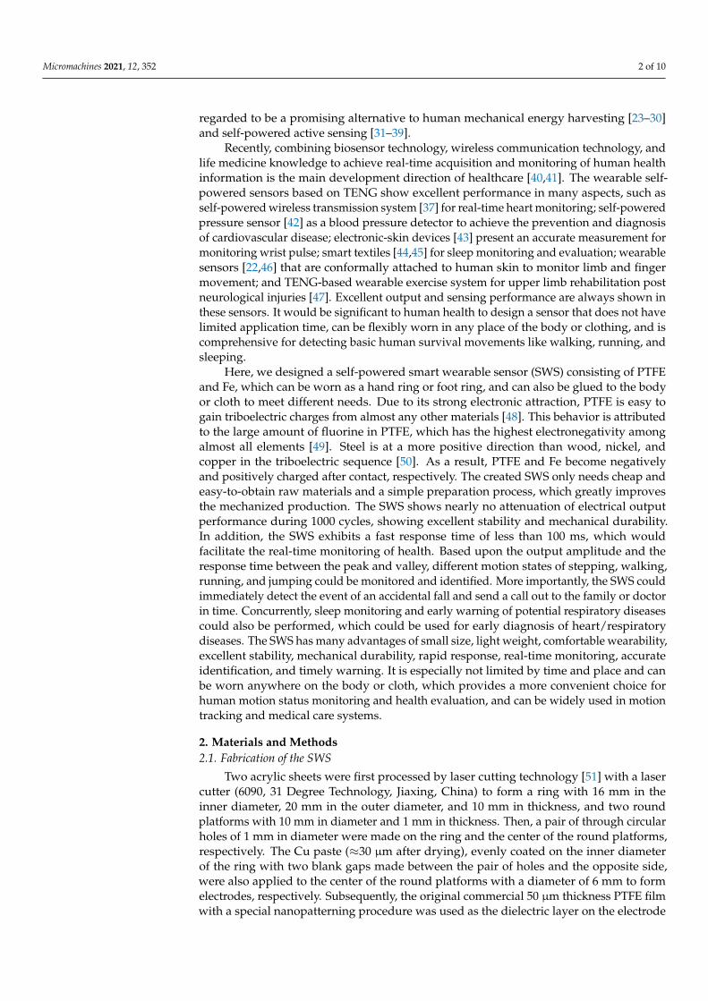
Experimental setup for the fundamental test is presented in Figure S1. First, theresponse of the SWS to various pressing frequencies was explored. Previous studies ofexamined energy of particular human motions indicate that human motion is a combi-nation of low frequency vibrations (≤10 Hz), the dominant motion frequency range was1.1–3.8 Hz [52]. The VOC of two channels of the SWS in the frequency range of 0.5 Hz to3 Hz moving in the circumference direction, and the top and bottom direction is demon-strated in Figure 2a,b, respectively. The influence of noise was distinctive when voltagedata were very small at 0.5 Hz and 1 Hz. The voltage increased with the increase of thefrequency, and the noise was less obvious. The peaks for higher frequencies were clearer.Simultaneously, with the increasing of the frequency, the VOC first increased and thendecreased when rotating along the circumference, while the VOC continuously increasedwhen jumping top and bottom. It was likely that a poor contact between the Fe ball and theside existed at a faster frequency. Therefore, it looked like there was no outstanding linearoutput voltage depending on the frequency. The output of the SC was larger than TBC,when moving in a circumference direction but was opposite in the top and down direction.It was mainly affected by the direction of the applied force, the channel in the direction ofthe applied force would be larger than the other channel. The VOC of two channels of theSWS when rotating along the circumference was slightly larger than that jumping top andbottom, because the contact area of the dielectric layer of the SC was bigger than that of theTBC, which was also consistent with the basic principle of TENG.
Micromachines 2021, 12, 352 5 of 10Micromachines 2021, 12, x FOR PEER REVIEW 5 of 11
Figure 2. Electrical and mechanical characterization of the SWS. VOC of the SWS at various pressing frequencies in different moving directions. (a) Circumference direction; and (b) top and bottom direction. (c) The mechanical durability charac-terization of the SWS with 1000 continuous working cycles at 1.5 Hz. (d) Response time of the VOC when the external stimulus was applied and released at the acceleration of 1.7 m/s2. (e) Water resistance of the SWS.
To summarize the influence of the triboelectric materials, number of channels, and moving direction on the basic performance of the SWS, the basic electrical outputs of side-channel Fe-triboelectric SWS (FT-SWS) (Figure S2a) and side-channel PA-triboelectric SWS (PT-SWS) (Figure S2b) moving in the circumference direction; dual-channel PT-SWS moving in circumference direction (Figure S2c), and top and down direction (Figure S2d) were researched separately. The VOC of two-channel PT-SWS rotating along the circumfer-ence fit better with the changing trend, while the SC of two-channel PT-SWS could not follow the changing trend well when it jumped up and down. This was perhaps owing to the lighter weight of the PA ball. In summary, the dual-channel FT-SWS had preferable sensitivity and practicality.
To discuss the mechanical properties of the SWS, the durability of the SWS was char-acterized by 1000 cycles at 1.5 Hz, represented in Figure 2c. The inset was SEM images after 1000 cycles, we could see that there was no obvious abrasion. It indicated the excel-lent stability, durability, and wear resistance of the sensor. As can be seen in Figure 2d, the response time of the SWS to the external load was taken care of. When the acceleration was about 1.7 m/s2, the response times of the two channels moving in two directions were less than 100 ms. Rapid response made sure that the SWS could catch the signals in time, under the action of the external stimulus. For verifying the credible of the SWS in wet environments like sports sweating, rain, snow, and other extreme weather, the water re-sistance of the SWS in a beaker containing water was tested, as illustrated in Figure 2e. The SWS was coated with a thin layer of silica gel to achieve the dual effects of protecting the electrodes and waterproofing simultaneously, as shown in Video S3. These results demonstrated that the SWS had the advantages of high sensitivity to external stimulus, long cycle stability, short response time, and excellent water resistance, which promoted the great potential of the SWS in health monitoring.
Figure 2. Electrical and mechanical characterization of the SWS. VOC of the SWS at various pressing frequencies indifferent moving directions. (a) Circumference direction; and (b) top and bottom direction. (c) The mechanical durabilitycharacterization of the SWS with 1000 continuous working cycles at 1.5 Hz. (d) Response time of the VOC when the externalstimulus was applied and released at the acceleration of 1.7 m/s2. (e) Water resistance of the SWS.
To summarize the influence of the triboelectric materials, number of channels, andmoving direction on the basic performance of the SWS, the basic electrical outputs of side-channel Fe-triboelectric SWS (FT-SWS) (Figure S2a) and side-channel PA-triboelectric SWS(PT-SWS) (Figure S2b) moving in the circumference direction; dual-channel PT-SWS movingin circumference direction (Figure S2c), and top and down direction (Figure S2d) wereresearched separately. The VOC of two-channel PT-SWS rotating along the circumference fitbetter with the changing trend, while the SC of two-channel PT-SWS could not follow thechanging trend well when it jumped up and down. This was perhaps owing to the lighterweight of the PA ball. In summary, the dual-channel FT-SWS had preferable sensitivity andpracticality.
To discuss the mechanical properties of the SWS, the durability of the SWS wascharacterized by 1000 cycles at 1.5 Hz, represented in Figure 2c. The inset was SEM imagesafter 1000 cycles, we could see that there was no obvious abrasion. It indicated the excellentstability, durability, and wear resistance of the sensor. As can be seen in Figure 2d, theresponse time of the SWS to the external load was taken care of. When the accelerationwas about 1.7 m/s2, the response times of the two channels moving in two directionswere less than 100 ms. Rapid response made sure that the SWS could catch the signals intime, under the action of the external stimulus. For verifying the credible of the SWS inwet environments like sports sweating, rain, snow, and other extreme weather, the waterresistance of the SWS in a beaker containing water was tested, as illustrated in Figure 2e.The SWS was coated with a thin layer of silica gel to achieve the dual effects of protectingthe electrodes and waterproofing simultaneously, as shown in Video S3. These resultsdemonstrated that the SWS had the advantages of high sensitivity to external stimulus,long cycle stability, short response time, and excellent water resistance, which promotedthe great potential of the SWS in health monitoring.

Micromachines 2021, 12, 352 6 of 10
3.3. Monitoring of Motion State
Due to the convenient and comfortable wearability of the SWS, it could be placed ondifferent parts of the human body. Figure 3a displays the signals of the SWS when it waslaid on the wrist. When the wrist swung forward, a valley could be detected; when thewrist swung back, a peak could be detected. The amplitude and response time under eachmotion state were different. As the state of motion became more intense from stepping,walking to running, the amplitude increased and the response time decreased. Moreover,the amplitude of the SC was slightly larger than TBC, thanks to the smaller gap on theside. The amplitude of jumping was the largest, which probably related to the accelerationof gravity. The amplitude of the fall-down was the smallest. Similarly, Figure 3b showsoutput changes under different motion states where the SWS was placed on the side ofthe shoe to monitor the movement state. When the shoe stepped on the floor, a valleycould be detected, when the shoe left the floor, a peak could be detected. The amplitudeand response time corresponding to each movement state was the same as that worn onthe wrist. Additionally, the voltage was slightly larger, which was possibly a result of thegreater external stimulus exerted on the shoe. The amplitude and the response time werekey factors for monitoring different exercise states.
Micromachines 2021, 12, x FOR PEER REVIEW 7 of 11
Figure 3. Motion state monitoring signals (Step, Walk, Run, Jump, Fall-down) of the SWS in different wearing parts—(a) wrist and (b) shoe.
3.4. Fall-Down Alarm System and Sleep Monitoring To demonstrate that the SWS can serve as a sensing device for actual scenarios, a real-
time health monitoring system was invented. The system is constructed of SWS, MCU, Bluetooth transmitter, Bluetooth receiver, and an analysis software, which is expressed in Figure 4a. The system could be used as a remote fall-down alarm system for the elderly and patients. To demonstrate this function, an SWS was placed on the side of the shoe. Different output signals are generated when users put on the shoe with the SWS for dif-ferent sports, as shown in Figure 3b. By comparing the amplitude of the analogy signals (AS) of SWS, the MCU could process and provide a control signal (CS) ‘0′ or ‘1′. Then, the signal was sent by the Bluetooth transmitter to a Bluetooth receiver, as a notification. Fig-ure 4a illustrates in detail. (I) When the user walks, the SWS continuously generates elec-tric output, MCU indicates ‘0′, and the phone displays the status as “walking”. (II) If the user falls down on the ground, the SWS does not produce electrical output, MCU indicates ‘1′, the phone changes the status to “fall down” and activates an alert, meanwhile the app drives the phone to make a call to the added relatives or family doctors in a few seconds. This process is also shown in Video S4. It needs to be noted that so far no false alarm in the health monitoring of healthy people was observed, but it had a possibility of false alarm in the later monitoring of actual disabled people and the elderly. With the emer-gence of above problem, we will further improve the system.
Figure 3. Motion state monitoring signals (Step, Walk, Run, Jump, Fall-down) of the SWS in different wearing parts—(a)wrist and (b) shoe.
Equally, in order to summarize the influence of the number of channels, triboelectricmaterials, and wearing parts on the SWS in actual application scenarios, the signals of thesingle-channel FT-SWS (Figure S3a), PT-SWS (Figure S3b) when they were on the wrist andshoe, two-channel PT-SWS on wrist (Figure S4a) and shoe (Figure S4b) were researched,respectively. From stepping, walking, running, jumping to falling down, the peak shape,amplitude, and response time of each movement state was recognizable but not so obvious.Monitoring the motion state, especially fall-down state, we needed the output of the SC

Micromachines 2021, 12, 352 7 of 10
and TBC simultaneously. Signals of the two-channel PT-SWS were a little bit smaller thanthat the FT-SWS, owing to the weight of the ball. Hence, the two-channel FT-SWS waschosen to conduct the next experiments and explorations. Moreover, the SWS could easilyidentify the state of motion, as well as expand its application in motion tracking, activityrecognition, sports training, and other fields. For example, the travel distance (s) andmotion speed (v) could be obtained by the equation expressed as Note S1.
3.4. Fall-Down Alarm System and Sleep Monitoring
To demonstrate that the SWS can serve as a sensing device for actual scenarios, areal-time health monitoring system was invented. The system is constructed of SWS, MCU,Bluetooth transmitter, Bluetooth receiver, and an analysis software, which is expressed inFigure 4a. The system could be used as a remote fall-down alarm system for the elderly andpatients. To demonstrate this function, an SWS was placed on the side of the shoe. Differentoutput signals are generated when users put on the shoe with the SWS for different sports,as shown in Figure 3b. By comparing the amplitude of the analogy signals (AS) of SWS, theMCU could process and provide a control signal (CS) ‘0′ or ‘1′. Then, the signal was sentby the Bluetooth transmitter to a Bluetooth receiver, as a notification. Figure 4a illustratesin detail. (I) When the user walks, the SWS continuously generates electric output, MCUindicates ‘0′, and the phone displays the status as “walking”. (II) If the user falls downon the ground, the SWS does not produce electrical output, MCU indicates ‘1′, the phonechanges the status to “fall down” and activates an alert, meanwhile the app drives thephone to make a call to the added relatives or family doctors in a few seconds. This processis also shown in Video S4. It needs to be noted that so far no false alarm in the healthmonitoring of healthy people was observed, but it had a possibility of false alarm in thelater monitoring of actual disabled people and the elderly. With the emergence of aboveproblem, we will further improve the system.
Micromachines 2021, 12, x FOR PEER REVIEW 8 of 11
Figure 4. Demonstrations of the SWS for (a) motion state monitoring and fall-down alarm system and (b) sleep state monitoring.
The SWS was also placed on the neck to monitor the sleep state in actual time, as displayed in Figure 4b. When the user lay flat on the bed and breathed normally, the am-plitude was small and response time was long. During sleep, breaths become shorter, the amplitude increases and the response time decreases. The amplitude and response time are almost 0, when sleep becomes terrible, and sleep apnea syndrome attacks. Individual health monitoring and medical care can be carried out according to the differences of am-plitude and response time. During occurrence of tachypnea/dyspnea, inability of self-reg-ulation (output signal shortness), obstructive apnea (output signal disappearance), the monitoring system can timely remind family members/doctors. This system can be used for early diagnosis of heart/respiratory diseases.
When the wearer turns over to the right, it can be observed that there is a peak in the SC and a valley in the TBC. When turning back from right to left, the SC has a valley, and the TBC has peak and valley. Interestingly, when turning left and turning back from left to right, the peak shape is just the opposite of the above. There is one output for each turn, and the peak shape of left and right turns are different. Family members can judge whether the distance from the bedside is dangerous according to the peak shape and the number of turns. It is significant for the healthy growth of babies and attention deficit hyperactivity disorder patients, and healthcare of elderly or patients with unconscious-ness. All these applications demonstrate the potential of the SWS in self-powered intelli-gent sensor systems.
4. Conclusions In summary, a wearable and practical smart sensor based on two-channel TENG is
demonstrated for true-time health monitoring. The SWS have many outstanding ad-vantages, including simple manufacturing, low cost, convenient wearability, high dura-bility, short response time, and excellent water resistance, which is not limited by time and place and can be worn anywhere on the body or cloth, according to needs. The SWS can not only realize real-time health monitoring, but is also suitable for mass production. In addition, the designed SWS can distinguish different motion states, such as stepping, walking, running, jumping, and can calculate movement distance and speed at the same
Figure 4. Demonstrations of the SWS for (a) motion state monitoring and fall-down alarm system and (b) sleep statemonitoring.
The SWS was also placed on the neck to monitor the sleep state in actual time, asdisplayed in Figure 4b. When the user lay flat on the bed and breathed normally, the

Micromachines 2021, 12, 352 8 of 10
amplitude was small and response time was long. During sleep, breaths become shorter,the amplitude increases and the response time decreases. The amplitude and response timeare almost 0, when sleep becomes terrible, and sleep apnea syndrome attacks. Individualhealth monitoring and medical care can be carried out according to the differences ofamplitude and response time. During occurrence of tachypnea/dyspnea, inability of self-regulation (output signal shortness), obstructive apnea (output signal disappearance), themonitoring system can timely remind family members/doctors. This system can be usedfor early diagnosis of heart/respiratory diseases.
When the wearer turns over to the right, it can be observed that there is a peak inthe SC and a valley in the TBC. When turning back from right to left, the SC has a valley,and the TBC has peak and valley. Interestingly, when turning left and turning back fromleft to right, the peak shape is just the opposite of the above. There is one output for eachturn, and the peak shape of left and right turns are different. Family members can judgewhether the distance from the bedside is dangerous according to the peak shape and thenumber of turns. It is significant for the healthy growth of babies and attention deficithyperactivity disorder patients, and healthcare of elderly or patients with unconsciousness.All these applications demonstrate the potential of the SWS in self-powered intelligentsensor systems.
4. Conclusions
In summary, a wearable and practical smart sensor based on two-channel TENG isdemonstrated for true-time health monitoring. The SWS have many outstanding advan-tages, including simple manufacturing, low cost, convenient wearability, high durability,short response time, and excellent water resistance, which is not limited by time and placeand can be worn anywhere on the body or cloth, according to needs. The SWS can not onlyrealize real-time health monitoring, but is also suitable for mass production. In addition, thedesigned SWS can distinguish different motion states, such as stepping, walking, running,jumping, and can calculate movement distance and speed at the same time. Meanwhilethe SWS can be used as an alarm system for a fall-down event, sleep breathing diseasesand sleep safety, which is of consequence to babies, the elderly, and potential patients. Thisresearch proposes a new design scheme for wearable motion monitoring equipment, whichcan be further applied to motion recognition, remote medical care monitoring, and otherhealth assessments.
Supplementary Materials: The following are available online at https://www.mdpi.com/2072-666X/12/4/352/s1. Figure S1: Experimental setup for the fundamental test. Figure S2: Electricalcharacterization of the SWS with different triboelectric materials, number of channels and movingdirections—side-channel (a) FT-SWS, and (b) PT-SWS rotating along the circumference; dual-channelPT-SWS moving in (c) circumference direction and (d) top and down direction. Figure S3: Motionstate monitoring signals of side-channel (a) FT-SWS and (b) PT-SWS when they were put on the wristand shoe. Figure S4: Motion state monitoring signals of two-channel PT-SWS in different wearingparts—(a) wrist and (b) shoe. Note S1. The equation of travel distance and motion speed obtained bythe sensor. Video S1. The COMSOL simulation animation of SC. Video S2. The COMSOL simulationanimation of TBC. Video S3: Water resistance of the SWS. Video S4: Fall-down alarm system basedon the SWS.
Author Contributions: Conceptualization, methodology, and project administration, Z.W. and X.W.;software, Z.W.; validation, investigation, data curation and writing—original draft preparation, R.L.;writing—review and editing, R.L., X.W., Z.W. and Z.L.W.; visualization, J.X. and J.C.; resources, B.L.All authors have read and agreed to the published version of the manuscript.
Funding: This research was funded by the National Key R&D Program of China (2016YFA0202701).
Data Availability Statement: The data presented in this study are available from all authors.
Conflicts of Interest: The authors declare no conflict of interest.

Micromachines 2021, 12, 352 9 of 10
References1. Wu, F.; Wu, T.; Yuce, M.R. An Internet-of-Things (IoT) Network System for Connected Safety and Health Monitoring Applications.
Sensors 2019, 19, 21. [CrossRef] [PubMed]2. Wang, H.; Cheng, J.; Wang, Z.; Ji, L.; Wang, Z.L. Triboelectric nanogenerators for human-health care. Sci. Bull. 2020, 66, 490–511.
[CrossRef]3. Li, J.; Tichy, J.; Borca-Tasciuc, D.-A. A predictive model for electrostatic energy harvesters with impact-based frequency up-
conversion. J. Micromech. Microeng. 2020, 30, 125012. [CrossRef]4. Erturun, U.; Eisape, A.; West, J.E. Design and analysis of a vibration energy harvester using push-pull electrostatic conversion.
Smart Mater. Struct. 2020, 29, 105018. [CrossRef]5. Wu, Z.; Bian, L.; Wang, S.; Zhang, X. An angle sensor based on magnetoelectric effect. Sens. Actuators A Phys. 2017, 262, 108–113.
[CrossRef]6. Pan, X.; He, X.; Wu, H.; Ju, C.; Jiang, Z.; Gao, J. Optimal Design of Novel Electromagnetic-Ring Active Balancing Actuator with
Radial Excitation. Chin. J. Mech. Eng. 2021, 34, 9. [CrossRef]7. Lee, H.; Roh, J.-S. Charging device for wearable electromagnetic energy-harvesting textiles. Fash. Text. 2021, 8, 5. [CrossRef]8. Zhang, C.; Zhang, Q.; Zhang, D.; Wang, M.; Bo, Y.; Fan, X.; Li, F.; Liang, J.; Huang, Y.; Ma, R.; et al. Highly Stretchable Carbon
Nanotubes/Polymer Thermoelectric Fibers. Nano Lett. 2021, 21, 1047–1055. [CrossRef]9. Ren, W.; Sun, Y.; Zhao, D.; Aili, A.; Zhang, S.; Shi, C.; Zhang, J.; Geng, H.; Zhang, J.; Zhang, L.; et al. High-performance wearable
thermoelectric generator with self-healing, recycling, and Lego-like reconfiguring capabilities. Sci. Adv. 2021, 7, eabe0586.[CrossRef]
10. Park, K.T.; Lee, T.; Ko, Y.; Cho, Y.S.; Park, C.R.; Kim, H. High-Performance Thermoelectric Fabric Based on a Stitched CarbonNanotube Fiber. ACS Appl. Mater. Interfaces 2021, 13, 6257–6264. [CrossRef]
11. Wang, Z.L.; Song, J.H. Piezoelectric nanogenerators based on zinc oxide nanowire arrays. Science 2006, 312, 242–246. [CrossRef][PubMed]
12. Kim, J.H.; Kim, B.; Kim, S.-W.; Kang, H.W.; Park, M.-C.; Park, D.H.; Ju, B.K.; Choi, W.K. High-performance coaxial piezoelectricenergy generator (C-PEG) yarn of Cu/PVDF-TrFE/PDMS/Nylon/Ag. Nanotechnology 2021, 32, 145401. [CrossRef]
13. Wu, Z.; Tang, J.; Zhang, X.; Yu, Z. An energy harvesting bracelet. Appl. Phys. Lett. 2017, 111, 4991666. [CrossRef]14. Peng, X.; Dong, K.; Ye, C.; Jiang, Y.; Zhai, S.; Cheng, R.; Liu, D.; Gao, X.; Wang, J.; Wang, Z.L. A breathable, biodegradable,
antibacterial, and self-powered electronic skin based on all-nanofiber triboelectric nanogenerators. Sci. Adv. 2020, 6, eaba9624.[CrossRef]
15. Wang, Z.L. Triboelectric Nanogenerator (TENG)—Sparking an Energy and Sensor Revolution. Adv. Energy Mater. 2020, 10,2000137. [CrossRef]
16. Wang, Z.L. New wave power. Nature 2017, 542, 159–160. [CrossRef] [PubMed]17. Wang, Z.L. On Maxwell’s displacement current for energy and sensors: The origin of nanogenerators. Mater. Today 2017, 20,
74–82. [CrossRef]18. Wang, Z.L. Triboelectric nanogenerators as new energy technology and self-powered sensors—Principles, problems and perspec-
tives. Faraday Discuss. 2014, 176, 447–458. [CrossRef]19. Wu, Z.; Cheng, T.; Wang, Z.L. Self-Powered Sensors and Systems Based on Nanogenerators. Sensors 2020, 20, 2925. [CrossRef]
[PubMed]20. Chen, X.; Wu, Y.; Shao, J.; Jiang, T.; Yu, A.; Xu, L.; Wang, Z.L. On-Skin Triboelectric Nanogenerator and Self-Powered Sensor with
Ultrathin Thickness and High Stretchability. Small 2017, 13, 1702929. [CrossRef]21. Tat, T.; Libanori, A.; Au, C.; Yau, A.; Chen, J. Advances in triboelectric nanogenerators for biomedical sensing. Biosens. Bioelectron.
2021, 171, 112714. [CrossRef]22. Jiang, Y.; Dong, K.; Li, X.; An, J.; Wu, D.; Peng, X.; Yi, J.; Ning, C.; Cheng, R.; Yu, P.; et al. Stretchable, Washable, and Ultrathin
Triboelectric Nanogenerators as Skin-Like Highly Sensitive Self-Powered Haptic Sensors. Adv. Funct. Mater. 2020, 31, 2005584.[CrossRef]
23. Zhu, G.; Chen, J.; Zhang, T.; Jing, Q.; Wang, Z.L. Radial-arrayed rotary electrification for high performance triboelectric generator.Nat. Commun. 2014, 5, 3426. [CrossRef]
24. Ouyang, H.; Liu, Z.; Li, N.; Shi, B.; Zou, Y.; Xie, F.; Ma, Y.; Li, Z.; Li, H.; Zheng, Q.; et al. Symbiotic cardiac pacemaker. Nat.Commun. 2019, 10, 1821. [CrossRef]
25. Niu, S.; Wang, X.; Yi, F.; Zhou, Y.S.; Wang, Z.L. A universal self-charging system driven by random biomechanical energy forsustainable operation of mobile electronics. Nat. Commun. 2015, 6, 8975. [CrossRef]
26. Liu, Z.; Nie, J.; Miao, B.; Li, J.; Cui, Y.; Wang, S.; Zhang, X.; Zhao, G.; Deng, Y.; Wu, Y.; et al. Self-Powered Intracellular DrugDelivery by a Biomechanical Energy-Driven Triboelectric Nanogenerator. Adv. Mater. 2019, 31, e1807795. [CrossRef] [PubMed]
27. Lin, Z.; Zhang, B.; Guo, H.; Wu, Z.; Zou, H.; Yang, J.; Wang, Z.L. Super-robust and frequency-multiplied triboelectric nanogenera-tor for efficient harvesting water and wind energy. Nano Energy 2019, 64, 103908. [CrossRef]
28. Chen, J.; Huang, Y.; Zhang, N.; Zou, H.; Liu, R.; Tao, C.; Fan, X.; Wang, Z.L. Micro-cable structured textile for simultaneouslyharvesting solar and mechanical energy. Nat. Energy 2016, 1, 16138. [CrossRef]
29. Cho, S.; Yun, Y.; Jang, S.; Ra, Y.; Choi, J.H.; Hwang, H.J.; Choi, D.; Choi, D. Universal biomechanical energy harvesting from jointmovements using a direction-switchable triboelectric nanogenerator. Nano Energy 2020, 71, 104584. [CrossRef]

Micromachines 2021, 12, 352 10 of 10
30. Choi, S.; Cho, S.; Yun, Y.; Jang, S.; Choi, J.H.; Ra, Y.; La, M.; Park, S.J.; Choi, D. Development of a High-Performance HandheldTriboelectric Nanogenerator with a Lightweight Power Transmission Unit. Adv. Mater. Technol. 2020, 5, 2000003. [CrossRef]
31. Yang, J.; Chen, J.; Su, Y.; Jing, Q.; Li, Z.; Yi, F.; Wen, X.; Wang, Z.; Wang, Z.L. Eardrum-Inspired Active Sensors for Self-PoweredCardiovascular System Characterization and Throat-Attached Anti-Interference Voice Recognition. Adv. Mater. 2015, 27,1316–1326. [CrossRef]
32. Wang, Z.L. Triboelectric Nanogenerators as New Energy Technology for Self-Powered Systems and as Active Mechanical andChemical Sensors. ACS Nano 2013, 7, 9533–9557. [CrossRef] [PubMed]
33. Wang, P.; Liu, R.; Ding, W.; Zhang, P.; Pan, L.; Dai, G.; Zou, H.; Dong, K.; Xu, C.; Wang, Z.L. Complementary Electromagnetic-Triboelectric Active Sensor for Detecting Multiple Mechanical Triggering. Adv. Funct. Mater. 2018, 28, 1705808. [CrossRef]
34. Lin, Z.; Chen, J.; Li, X.; Zhou, Z.; Meng, K.; Wei, W.; Yang, J.; Wang, Z.L. Triboelectric Nanogenerator Enabled Body SensorNetwork for Self-Powered Human Heart-Rate Monitoring. ACS Nano 2017, 11, 8830–8837. [CrossRef] [PubMed]
35. Chen, J.; Wang, Z.L. Reviving Vibration Energy Harvesting and Self-Powered Sensing by a Triboelectric Nanogenerator. Joule2017, 1, 480–521. [CrossRef]
36. Pu, X.; Guo, H.; Chen, J.; Wang, X.; Xi, Y.; Hu, C.; Wang, Z.L. Eye motion triggered self-powered mechnosensational communica-tion system using triboelectric nanogenerator. Sci. Adv. 2017, 3, e1700694. [CrossRef] [PubMed]
37. Zheng, Q.; Zhang, H.; Shi, B.; Xue, X.; Liu, Z.; Jin, Y.; Ma, Y.; Zou, Y.; Wang, X.; An, Z.; et al. In Vivo Self-Powered Wireless CardiacMonitoring via Implantable Triboelectric Nanogenerator. ACS Nano 2016, 10, 6510–6518. [CrossRef]
38. Ra, Y.; La, M.; Cho, S.; Park, S.J.; Choi, D. Scalable Batch Fabrication of Flexible, Transparent and Self-triggered Tactile SensorArray Based on Triboelectric Effect. Int. J. Pr. Eng. Mangt. 2021, 8, 519–531. [CrossRef]
39. Garcia, C.; Trendafilova, I.; del Rio, J.S. Detection and measurement of impacts in composite structures using a self-poweredtriboelectric sensor. Nano Energy 2019, 56, 443–453. [CrossRef]
40. Alotaibi, Y.K.; Federico, F. The impact of health information technology on patient safety. Saudi Med. J. 2017, 38, 1173–1180.[CrossRef] [PubMed]
41. Behmanesh, A.; Sayfouri, N.; Sadoughi, F. Technological Features of Internet of Things in Medicine: A Systematic Mapping Study.Wirel. Commun. Mob. Comput. 2020, 2020, 27. [CrossRef]
42. Meng, K.; Chen, J.; Li, X.; Wu, Y.; Fan, W.; Zhou, Z.; He, Q.; Wang, X.; Fan, X.; Zhang, Y.; et al. Flexible Weaving ConstructedSelf-Powered Pressure Sensor Enabling Continuous Diagnosis of Cardiovascular Disease and Measurement of Cuffless BloodPressure. Adv. Funct. Mater. 2018, 29, 1806388. [CrossRef]
43. Wang, X.; Gu, Y.; Xiong, Z.; Cui, Z.; Zhang, T. Silk-Molded Flexible, Ultrasensitive, and Highly Stable Electronic Skin forMonitoring Human Physiological Signals. Adv. Mater. 2014, 26, 1336–1342. [CrossRef]
44. Lin, Z.; Yang, J.; Li, X.; Wu, Y.; Wei, W.; Liu, J.; Chen, J.; Yang, J. Large-Scale and Washable Smart Textiles Based on TriboelectricNanogenerator Arrays for Self-Powered Sleeping Monitoring. Adv. Funct. Mater. 2018, 28, 1704112. [CrossRef]
45. Zhou, Z.; Padgett, S.; Cai, Z.; Conta, G.; Wu, Y.; He, Q.; Zhang, S.; Sun, C.; Liu, J.; Fan, E.; et al. Single-layered ultra-soft washablesmart textiles for all-around ballistocardiograph, respiration, and posture monitoring during sleep. Biosens. Bioelectron. 2020, 155,112064. [CrossRef] [PubMed]
46. Ning, C.; Dong, K.; Cheng, R.; Yi, J.; Ye, C.; Peng, X.; Sheng, F.; Jiang, Y.; Wang, Z.L. Flexible and Stretchable Fiber-ShapedTriboelectric Nanogenerators for Biomechanical Monitoring and Human-Interactive Sensing. Adv. Funct. Mater. 2020, 31, 2006679.[CrossRef]
47. Bhatia, D.; Jo, S.H.; Ryu, Y.; Kim, Y.; Kim, D.H.; Park, H.-S. Wearable triboelectric nanogenerator based exercise system for upperlimb rehabilitation post neurological injuries. Nano Energy 2021, 80, 105508. [CrossRef]
48. Garcia, C.; Trendafilova, I. Real-time diagnosis of small energy impacts using a triboelectric nanosensor. Sens. Actuators A Phys.2019, 291, 196–203. [CrossRef]
49. Garcia, C.; Trendafilova, I.; de Villoria, R.G.; del Rio, J.S. Self-powered pressure sensor based on the triboelectric effect and itsanalysis using dynamic mechanical analysis. Nano Energy 2018, 50, 401–409. [CrossRef]
50. Zou, H.; Zhang, Y.; Guo, L.; Wang, P.; He, X.; Dai, G.; Zheng, H.; Chen, C.; Wang, A.C.; Xu, C.; et al. Quantifying the triboelectricseries. Nat. Commun. 2019, 10, 1427. [CrossRef]
51. Caiazzo, F.; Curcio, F.; Daurelio, G.; Minutolo, F.M.C. Laser cutting of different polymeric plastics (PE, PP and PC) by a CO2 laserbeam. J. Mater. Process. Technol. 2005, 159, 279–285. [CrossRef]
52. Wu, S.; Luk, P.C.K.; Li, C.; Zhao, X.; Jiao, Z.; Shang, Y. An electromagnetic wearable 3-DoF resonance human body motion energyharvester using ferrofluid as a lubricant. Appl. Energy 2017, 197, 364–374. [CrossRef]