Smart Traffic Management System
29
SMART TRAFFIC MANAGEMENT SYSTEM Software Requirement Specification Version 1.1 31 st December 2012 Submitted to the FACULTY OF COMPUTER SCIENCE & ENGINEERING In partial fulfillment of the requirements For the award of the degree BACHELOR OF TECHNOLOGY IN COMPUTER SCIENCE&ENGINEERING By S. Anjani Devi(09L11A0505) M.Jagadeesh (09L11A0513) G.Satish Kumar (09L11A0531) L.Veera Kumar (10L15A0542) Under the Guidance of Prof. A.Veera swami sir, phd Department of Computer Science Engineering V.R.S & Y.R.N COLLEGE OF ENGINEERING &TECHNOLOGY 1 SOFTWARE REQUIREMENT SPECIFICATION
-
Upload
sambhav-jain -
Category
Documents
-
view
32 -
download
5
description
Smart Traffic Management System
Transcript of Smart Traffic Management System

SMART TRAFFIC MANAGEMENT SYSTEM
Software Requirement Specification
Version 1.1
31st December 2012
Submitted to the
FACULTY OF COMPUTER SCIENCE & ENGINEERING
In partial fulfillment of the requirements
For the award of the degree
BACHELOR OF TECHNOLOGY
IN
COMPUTER SCIENCE&ENGINEERING
By
S. Anjani Devi(09L11A0505)
M.Jagadeesh (09L11A0513) G.Satish Kumar (09L11A0531)
L.Veera Kumar (10L15A0542)
Under the Guidance of
Prof. A.Veera swami sir, phd
Department of Computer Science Engineering
V.R.S & Y.R.N COLLEGE OF ENGINEERING &TECHNOLOGY
(Approved By AICTE, Affiliated to JNTUK, Kakinada, A.P)
Vodarevu Road, Chirala (P.O), Prakasam (Dt.), A.P.-523157
Date Description Team Members Comments
1 SOFTWARE REQUIREMENT SPECIFICATION

31-12-2012
Smart Traffic
Management System
1.0
(STM version 1.0)
S.Anjani Devi
<First Revision>
M.Jagadeesh
L.Veera Kumar
G.Satish Kumar
Document Approval
The following Software Requirements Specification has been accepted and approved by the
following:
Date Name of the Guide Project TitleSignature of the
Guide
31-12-12 A. Veera SwamiSmart Traffic Management
System
2 SOFTWARE REQUIREMENT SPECIFICATION

Table of Contents
Table of Contents....................................................................................................................................................................... ii
Table of Figures........................................................................................................................................................................ iii
1.0. Introduction.......................................................................................................................................................................01
1.1 purpose…………………………………………………………………….........................................................................01
1.2. Scope…………………………………………………………………………………………………………………...01
1.3. Glossary…………………………………..........................................................................................................................01
1.4. References…………………...............................................................................................................................................01
1.5. Overview of document.......................................................................................................................................................01
1.6 Definitions,acronyms,and abbrivations………………………………………………………………………………………………………………01
1.7 Technologies to be used…………………………………………………………………………………………………………………………………….01
2.0. Overall description...........................................................................................................................................................02
2.1. System environment...........................................................................................................................................................02
2.2 Software Interface…………………………………………………………………………………………………………………………………………….02
2.3 Communication interface………………………………………………………………………………………………………………………………….02
2.4 User Characterstics…………………………………………………………………………………………………………………………………………….02
2.5 Constraints…………………………………………………………………………………………………………………………………………………………02
2.6 Architecture Design……………………………………………………………………………………………………………………………………………02
2.7 Usecase Diagram………………………………………………………………………………………………………………………………………………….02
2.8 Class Diagram……………………………………………………………………………………………………………………………………………………….02
2.9 Sequence Diagram………………………………………………………………………………………………………………………………………………..02
2.1.1 Activity Diagram…………………………………………………………………………………………………………………………………………………02
3.0. Requirement specification……………………………………………………………………………………………….03
3.1.Non-functionalrequirements…………………………………………………………………….. …..03
3.2Functional Requirements…………………………………………………………………………………………….. ……..03
3.2Login to STM……………………………………………………………………………………………………………………………………………………………03
3.2.2. Registration of pedestrains,vehicleowners,traffic police……….....................................................................................03
3.2.3. Compliant issued by users...............................................................................................................................................03
3.2.4Compliants undertaken by traffic......................................................................................................................................03
3.3. Specific Requirements………………………………………………………………………………………………….03
3.4 Dtailed non-functional requirements...................................................................................................................................03
3 SOFTWARE REQUIREMENT SPECIFICATION

1.0 . Introduction
Our intelligent Traffic Expert Solution for road traffic control System offers the ability to acquire
real-time traffic information, .Traffic Expert enables operators to perform real-time data analysis
on the information gathered. Traffic management measures are aimed at improving the safety
and flow of traffic utilizing traffic capacity more effectively.
1.1 Purpose
Smart Traffic Management is mainly improvised for looking after the Set off data of a region
to manage the Traffic along that area and implement various useful technologies which are
been required by various persons like vehicle owners, pedestrians, police officers
etc….Mainly the purpose of Smart traffic management system is to give the details which
can be used and they can be implemented in their daily life. The problems which have been
occurred at their presence can be solved by this Smart Traffic.
1.2 scope
Smart Traffic is a Video Analytics Module and provides Traffic Incident Detection, and
real time Traffic Flow Metrics & statistical analysis. Smart Traffic Monitoring can
integrate with third party traffic management and smart roadway systems and hosts a
feature rich product scope itself. The system can be used for incident detection or for
statistical metrics of a roadway.
1.3 Glossary
Term Definition
Traffic police He co-insides with the remaining users to upgrade the complaints and implement it.
Vehicle owners They use the traffic data and implement when they require.If they have any compliant they can provide.
AdminA Person who is designated the whole dataset which are require by the remaining users and maintain the whole project in a reasonable manner.
Pedestrains A Person(s) who uses the datasets provide by the admin and implement the ideas which he had .
2
4 SOFTWARE REQUIREMENT SPECIFICATION

1.4. References
1. Anderson, J. E. 2003. “Control of Personal Rapid Transit Systems.” Elektronikk , Vol. 99, No.
1, 108-116
2. Bretherton, D., Bowen, G., Wood, K. 2002. ‘Effective urban traffic management and control –
SCOOT VERSION 4.4’. Proceedings of European Transport Conference Proceedings
Cambridge.
3. Christos Xithalis, 2008, PRT Hermes
1.5. Overview:
The remainder of this document is two chapters, the first providing a full description of the
project for the Smart Management of the Traffic. It lists all the functions performed by the
system. The final chapter concerns details of each of the system functions and actions in full for
the software developers’ assistance.
1.6. Definitions, Acronyms, and Abbreviations:
HTML (Hyper Text Markup Language): It is used to create static web pages.
JSP (Java Server Pages): It is used to create dynamic web content.
J2EE (Java 2 Enterprise Edition): It is a programming platform, belonging to
the Java platform, which is used for developing and running distributed java
Applications.
DB2 (IBM Database 2): It is a database management system that provides a
Flexible and efficient database platform to raise a strong "on demand" business
HTTP (Hyper Text Transfer Protocol): It is a transaction oriented client/ server
Protocol between a web browser and a web server.
Database: Collection of information in a structured form.
Login ID: A user identification number to enter the system.
Password: A word that enables one to gain admission into the system.
XML (Extensible Markup Language): It is a markup language that was
designed to transport and store data.
Ajax (Asynchronous Java Script and XML): It is a technique used in java script to
create dynamic web pages.
ORACLE: It is software used in to insert Tables.
5 SOFTWARE REQUIREMENT SPECIFICATION

1.7 Technologies to be used:
J2EE: (Servlet, JSP, JAXP, Java Beans) Application architecture.
JAVA: Application architecture.
DB2: Database.
Ajax: Asynchronous Java Script and XML.
XML: Extension Markup Language.
WASCE: (Web Sphere Application Server Community Edition) Web Server.
TSM (Admin): Tivoli storage Manager Admin.
Soda: For developing use case reports.
Local Language Translator: For local language developing
ORACLE For inserting Tables.
2.0 Overall Description:
2.1 System Environment
6 SOFTWARE REQUIREMENT SPECIFICATION

database
Traffic police
vehicle owner
Pedestrains
Smart Traffic Managem...
The Smart Traffic management System has three active actors one cooperating system. Mainly pedestrians who uses the dataset provide by the admin and give the complaints important suggestions which are under taken by the traffic police and admins.where as the vehicle owners too generate the same idea of the pedestrians .Traffic police maintains the information which are provided by the users(pedestrains,vehicle owners)and make into implementation.These are all settled by the admin of STM.
2.2 Software Interface:
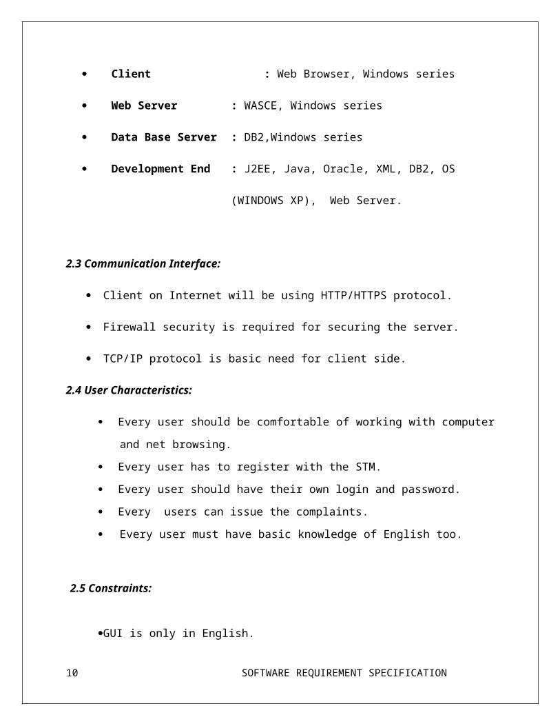
Client : Web Browser, Windows series
Web Server : WASCE, Windows series
Data Base Server : DB2,Windows series
Development End : J2EE, Java, Oracle, XML, DB2, OS
(WINDOWS XP), Web Server.
2.3 Communication Interface:
Client on Internet will be using HTTP/HTTPS protocol.
7 SOFTWARE REQUIREMENT SPECIFICATION

Firewall security is required for securing the server.
TCP/IP protocol is basic need for client side.
2.4 User Characteristics:
Every user should be comfortable of working with computer and net browsing.
Every user has to register with the STM.
Every user should have their own login and password.
Every users can issue the complaints.
Every user must have basic knowledge of English too.
2.5 Constraints:
GUI is only in English.
This system is working for single server.
Limited to HTTP/HTTPS.
User should have basic knowledge of computer.
2.6 Architecture Design:
8 SOFTWARE REQUIREMENT SPECIFICATION

In Model 2 architecture, a controller handles the user request instead of another JSP.The
controller is implemented as a Servlet. The following steps are executed when the user submits
the request.
The Controller Servlet handles the user’s request. (This means the hyperlink in the JSP
should point to the controller servlet).
The Controller Servlet then instantiates appropriate JavaBeans based on the request
parameters (and optionally also based on session attributes).
The Controller Servlet then by itself or through a controller helper communicates with
the middle tier or directly to the database to fetch the required data.
The Controller sets the resultant JavaBeans (either same or a new one) in one of the
following contexts – request, session or application.
The controller then dispatches the request to the next view based on the request URL.
The View uses the resultant JavaBeans from Step 4 to display data. Note that there is no
presentation logic in the JSP. The sole function of the JSP in Model
Architecture is to display the data from the JavaBeans set in the request, session or
application scopes.
2.7 Use Case Model Description:
A use case diagram in the Unified Modeling Language (UML) is a type of behavioral diagram
defined by and created from a Use-case analysis. Its purpose is to present a graphical overview
of the functionality provided by a system in terms of actors, their goals (represented as use
cases), and any dependencies between those use cases.
The main purpose of a use case diagram is to show what system functions are performed for
which actor. Roles of the actors in the system can be depicted.
Use Case diagrams are formally included in two modeling languages defined by the OMG:
the Unified Modeling Language (UML) and the Systems Modeling Language (SysML).
A use case analysis is the most common technique used to identify the requirements of a
system (normally associated with software/process design) and the information used to both
define processes used and classes (which are a collection of actors and processes) which will
9 SOFTWARE REQUIREMENT SPECIFICATION
be used both in the use case diagram and the overall use case in the development or redesign of
a software system or program. The use case analysis is the foundation upon which the system
will be built.
USECASE DIAGRAM:
compliants
Registrationvehicle owner
lisence receivd
recorded trafficsignal
control entire traffic
traffic police
Research
Rewrite Traffic data
check and provide other services
admin
pedestrains
view and information geathering
city traffic manager
check and handil compliants
2.8 Class Diagram description:
10 SOFTWARE REQUIREMENT SPECIFICATION

Class diagrams are widely used to describe the types of objects in a system and their
relationships. Class diagrams model class structure and contents using design elements such as
classes, packages and objects. Class diagrams describe three different perspectives when
designing a system, conceptual, specification, and implementation. These perspectives become
evident as the diagram is created and help solidify the design. This example is only meant as
an introduction to the UML and class diagrams. Classes are composed of three things: a name,
attributes, and operations. Mainly in the class diagram the names include about the traffic
management generation ideas which explain about the way how users admin and different
systems connect through this. Now the attributes include explanation which should be
implemented in the names. this could be shown in the form of operations. this can easily
explain how the general project is going to implement the various operations .the below
diagram represents the class diagram which gives the following road traffic management
system information.
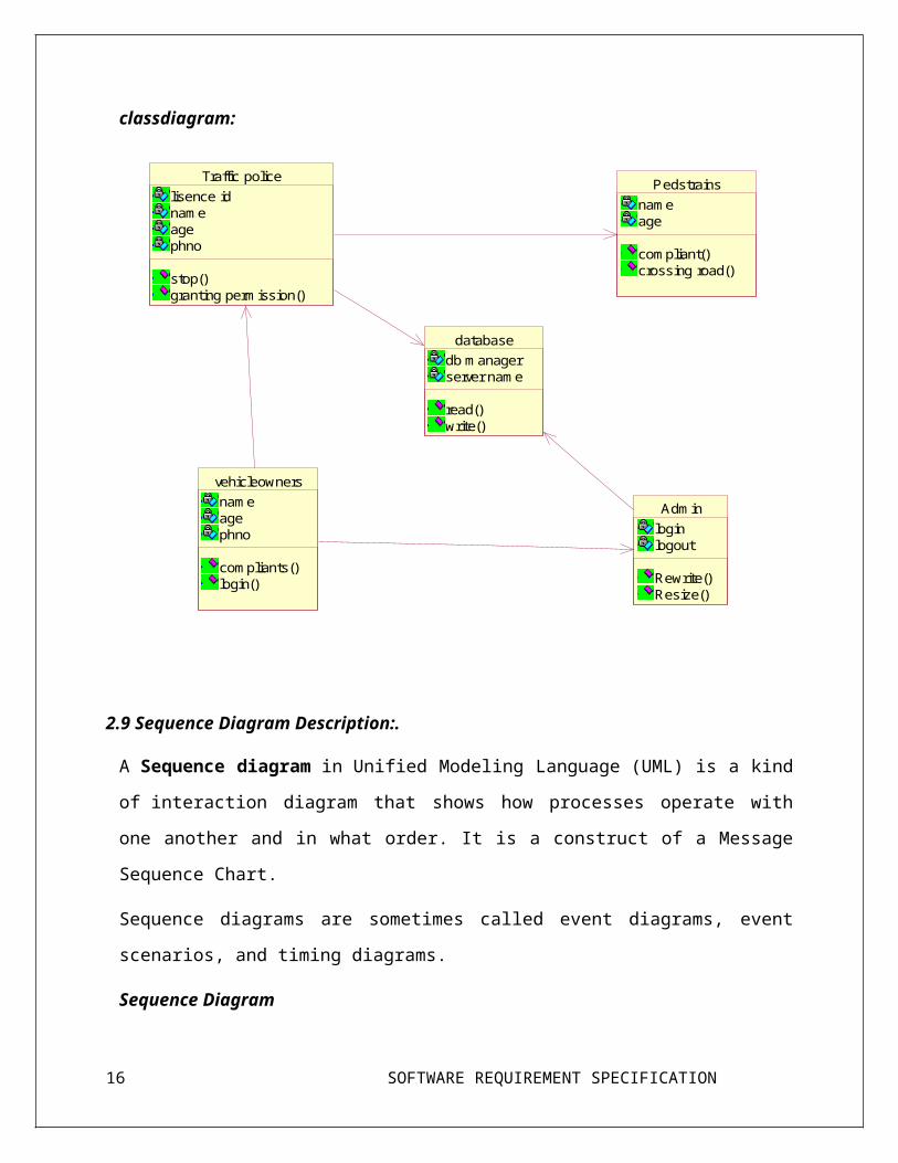
classdiagram:
database
db managerserver name
read()write()
Traffic police
lisence idnameagephno
stop()granting permission()
Pedstrains
nameage
compliant()crossing road()
vehicleowners
nameagephno
compliants()login()
Admin
loginlogout
Rewrite()Resize()
11 SOFTWARE REQUIREMENT SPECIFICATION

Pedestrains vehicle owners Traffic police DatabaseAuthority
Registration
Registration Form
Compliant
Compliant issued
Login
Login form
Traffic Information
Sends signals
Updating
Information updated
2.9 Sequence Diagram Description:.
A Sequence diagram in Unified Modeling Language (UML) is a kind of interaction diagram
that shows how processes operate with one another and in what order. It is a construct of a
Message Sequence Chart.
Sequence diagrams are sometimes called event diagrams, event scenarios, and timing
diagrams.
Sequence Diagram
12 SOFTWARE REQUIREMENT SPECIFICATION

2.1.1. Activity diagram Description
In activity diagram the object may be real or abstract in either case create a swim lane for each
attribute imported object, firstly identify the precondition of initial state and post condition of
final state.
Render the transaction that connect these actions and active states and state with sequential
flows consider branching, forking and joining.
Activity diagram:
conform the trafic information
diapatch the information
reqest is normal
no
Yes
YesYno
tremination
points
conditional check
user(vehicle owners,pedestrains)sen...
request sys conformation
start of the process
3.0 Requirement Specification:
3.1 Non Functional Requirements:
There are requirements that are not functional in nature. Specifically, these are the
constraints the system must work within.
13 SOFTWARE REQUIREMENT SPECIFICATION

1. Secure access of confidential data (user’s details). SSL can be used.
2. 24 X 7 availability
3. Better component design to get better performance at peak time.
4. Flexible service based architecture will be highly desirable for future extension.
3.2 Functional requirements:
3.2.1. Login to STM
Use Case Name: Login to STM
Priority Essential
Trigger Menu selection
Precondition The user should have a valid user id and
password
Basic Path 1. STM Web site contains login window for
each user
2. User should provide a valid user id and
password to access the STM web site
Alternate Path N/A
Post condition STM is on its home page
Exception Path The may abandon the search at any time.
Other N/A
3.2.2 Registration of Pedestrains,vehicle owners,traffic police of STM:
Use Case Name: Registration to STM
Priority Essential
Trigger Menu selection
Precondition The user (pedestrians,vehicle owners,traffic
police)should provide a valid information.
Basic Path 1. STM Web site contains Registration
14 SOFTWARE REQUIREMENT SPECIFICATION
window for each users
2. User should provide a valid details to
create account in the STM web site
Alternate Path N/A
Post condition STM is on its validation page of Admin.
Exception Path The may abandon the search at any time.
Other N/A
Reference SRS 2.7
3.2.3 Compliant issues by Pedestrains,vehicle owners.
Use Case Name: Complaints issued
Priority Essential
Trigger Menu selection
Precondition The user (vehicle owners,pedestrains) should
have to provide valid information to traffic
police through admin.
Basic Path 1. STM Web site contains Compliant issued
dialog box for every user
Alternate Path N/A
Post condition STM is a validation form for every user
Exception Path The may abandon the search at any time.
Other N/A
Reference SRS 2.8
3.2.4Compliants under taken by traffic police,admin in STM
Use Case Name: Compliant uner taken by traffic police
Priority Essential
Trigger Menu selection
15 SOFTWARE REQUIREMENT SPECIFICATION
Precondition The user (pedstrains,vehicle owners)can give
compliant any time to traffic police.
Basic Path 1. STM Web site contains Compliant issued
dialog box for every user
Alternate Path N/A
Post condition STM is on its validation page of traffic
police.
Exception Path The may abandon the search at any time.
Other N/A
Reference SRS 2.9
3.3 Specific Requirements:
Use Case Reports:
Use-Case-Model Survey for management system Smart traffic
1. Introduction
2. Actors
Users:
Documentation: User plays a main role in the project. In users we have different types of
users Traffic data which can he able to use and required login form for different users
who can register for maintaining the data.
Admin:
Documentation: Admin can manage all users and maintain their data securely1He can
update the details and day to day updating can be done by admin.
16 SOFTWARE REQUIREMENT SPECIFICATION

System:
Documentation: System can give the suggestions to the users during their discussion in
discussion forum. He /She will give the traffic details. For participating in discussion
forum he/she has to be registered.
Server:
Documentation: Smart Traffic Management plays a important role in maintaining data of
road Traffic of a region which is helpful to users.
Ask queries:
Documentation: User can ask any questions with the system and server during their chat
3 Contact systems:
Documentation: With the information provided by administrator user can directly contact
with system or he can contact during their chat.
Help user:
Documentation: Smart Traffic Management System can help by creating awareness.
Login:
Documentation: User can enter into his account only by login.
Logout:
Documentation: User can exit from his account.
Maintain all details:
Documentation: Administrator can maintain all backup data.
Participate in chat:
Documentation: User can participate in chat with system and SERVER.
System can participate in chat with user and SERVER.
17 SOFTWARE REQUIREMENT SPECIFICATION

Provide Traffic details:
Documentation: Admin has to provide the Traffic information to the user.
Respond Queries:
Documentation: System can respond to the queries asked by user.
Signup:
Documentation: For register their account user must be click on sign up
Update latest developments:
Documentation: Day to day updating in improvements of operations can be provided by
admin and they can be send to registered users every day
View Queries:
Documentation: System can view the queries which are asked by user.
View Response to Queries:
Documentation: User can view the response to their queries which are sent by system.
View Updates:
Documentation: User can view the updating provided by admin
4. Supplementary Requirements:
5. Performance Requirements:
System can withstand even though many no. of customers request the desired service. Access is
given to any users
6. Safety Requirements:
By incorporating a robust and proven DB2 UDB into the system, reliable performance and
integrity of data is ensured. There must be a power backup for server system. Since the product
18 SOFTWARE REQUIREMENT SPECIFICATION

is of 24x7 availability there should be power backup for server which provides the information.
Every day the data should be backup even when the operation of a user is not successful i.e.,
while performing the operation power failure occurs then data should be backup.
7. Security Requirements:
Sensitive data is protected from unwanted access by user’s appropriate technology and
implementing strict user-access criteria. Facility of unique user number and Password in such a
way that unauthorized user cannot log in. Operational rights for each user/terminal can be
defined. Thus, a user can have access to specific terminals and specific options only
3.4 Detailed functionl requirements:
Logical Database
Tables:
1. Pedestrains (users)
Attribute Name Attribute Type Attribute Size
LastName String 30
FirstName varchar 30
MaidenName varchar 30
Address1 varchar 50
Address2# varchar 50
City varchar 30
State varchar 2
Zip Int 6
Year Int 4
EmailAddress String 20
19 SOFTWARE REQUIREMENT SPECIFICATION

ReceiveEmails Boolean 1
Password String 10
2. Vehicle owners:
Attribute Name Attribute Type Attribute Size
FirstName String 30
LastName String 30
Address String 50
City String 30
State String 2
Year Int 4
EmailAddress String 20
Vehicle Registration
No
Varchar 20
Licence key int 10
Vehicle No: int 10
Password String 10
3. Traffic Police
20 SOFTWARE REQUIREMENT SPECIFICATION

Attribute Name Attribute Type Attribute Size
FirstName varchar 30
LastName varchar 30
City varchar 30
State varchar 10
Station area varchar 10
Email id varchar 20
password varchar 20
4. Admin
Attribute Name Attribute Type Attribute Size
username varchar 30
User id varchar 30
Email Id varchar 30
password varchar 10
Re-enter password varchar 10
References:
IEEE SRS format
Project specification requirement
21 SOFTWARE REQUIREMENT SPECIFICATION