Smart Structures Laboratory Brochure
20
Smart Structures Laboratory MELBOURNE, AUSTRALIA swinburne.edu.au/science-engineering-technology
Transcript of Smart Structures Laboratory Brochure

Smart Structures Laboratory
MELBOURNE, AUSTRALIA
swinburne.edu.au/science-engineering-technology

2
Swinburne University of Technology is
undergoing rapid growth, particularly in
the area of engineering education and
research. The Swinburne Advanced
Technologies Centre is a major investment
in new infrastructure and houses iconic
research equipment related to the
University’s areas of research, including
a new Smart Structures Laboratory.
The facility serves as part of the Centre
for Sustainable Infrastructure which
encourages testing of new and existing
systems, in addition to facilitating
investigations of new materials under
full-scale loading conditions. The research
outcomes derived from experimental
studies allow for the development and
calibration of numerical models in three
dimensions and provides significant
benefits to both industry and government
bodies by developing sustainable and
innovative solutions to complex problems.
The $15 million laboratory is a major
three-dimensional testing facility developed
for large scale testing of civil, mechanical,
aerospace and mining engineering
components and systems and the only one
of its type available in Australia. The 1.0m
thick strong floor measures some 20m x
8m in plan with two 5m tall reaction walls
meeting at one corner.
The 3D strong cell contains a grid of tie
down points 0.5m apart to secure the
test specimens in place, in addition to a
suite of hydraulic actuators and universal
testing machines varying in capacity from
10 tonnes to 500 tonnes. The laboratory
is serviced by adjacent workshops and
a hydraulic pump system located in the
basement. The facility is housed in a large
architecturally designed test hall about
8m tall, located prominently at the front
of the ATC building.
Smart Structures Laboratory at Swinburne

3
The Multi-Axis Substructure Testing System in the Smart Structures Laboratory provides a powerful tool for investigating the dynamic effects of earthquakes, hurricanes, and other extreme loading events on full scale structural systems and their components using quasi-static cyclic experimental testing or local/distributed hybrid simulation testing.
Large-scale testing of structural components can deliver significant benefits to structural and earthquake engineers. The behaviour of structural elements can be studied by replicating extreme loading conditions that currently cannot be produced by other means.
State-Of-The-Art System for Substructure Hybrid Simulation
Multi-Axis Substructure Testing System (MAST)
n 9 Tonne Crosshead
n 4 vertical 1000 kN ± 250 mm actuators
n 4 horizontal 500kN ± 250 mm actuators
n Test volume under crosshead 3m cube
n FlexTest 60 controller configured for 8 channels
Multi-Axis Substructure Testing (MAST) System
4
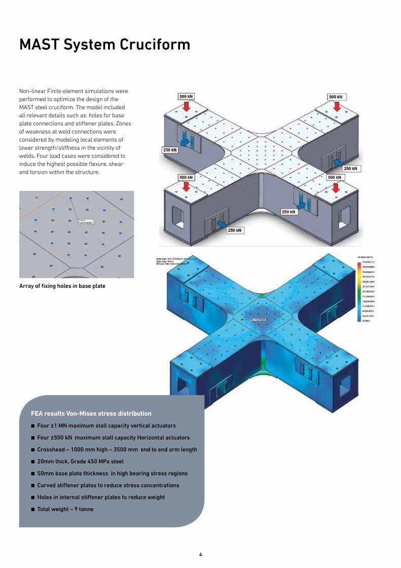
Non-linear Finite element simulations were performed to optimize the design of the MAST steel cruciform. The model included all relevant details such as: holes for base plate connections and stiffener plates. Zones of weakness at weld connections were considered by modeling local elements of lower strength/stiffness in the vicinity of welds. Four load cases were considered to induce the highest possible flexure, shear and torsion within the structure.
FEA results Von-Mises stress distribution
n Four ±1 MN maximum stall capacity vertical actuators
n Four ±500 kN maximum stall capacity Horizontal actuators
n Crosshead – 1000 mm high – 3500 mm end to end arm length
n 20mm thick, Grade 450 MPa steel
n 50mm base plate thickness in high bearing stress regions
n Curved stiffener plates to reduce stress concentrations
n Holes in internal stiffener plates to reduce weight
n Total weight – 9 tonne
MAST System Cruciform
Array of fixing holes in base plate

5
The 6 DOF hybrid testing facility introduces an array of possible loading conditions to both the strong floor and reaction wall. 3D solid models were constructed to assess the maximum load that may be applied to the reaction wall in any given configuration without exceeding the tensile strength of the concrete.
n 3D solid modeling
n Non-Linear Analysis
n 1000mm deep strong floor and reaction wall
n Concrete maintained in uncracked condition
FEA strong floor exaggerated deformations and srtress concentrations regions
MAST System Strong Floor and Reaction Wall
Over 100 load configurations were constructed to determine maximum allowable wall loading in any given scenario. Typically the load that could be applied to the strong floor was in excess of 1 MN. However, the loads which could be applied to the reaction wall were dependant on the height of the load, its distance from the wall edge and locations of neighbouring actuators.

6
Actuators
The actuators and associated control systems will allow for the development of new testing methodologies, including cyclic quasi-static, dynamic, pseudo-dynamic hybrid and the effective force control testing methods, in which large structures could be directly subjected to dynamic excitations.
n 2 mN (Qty. 1 set)
n 1 mN (Qty. 4 sets)
n 500 kN (Qty. 4 sets)
n 250 kN (Qty. 4 sets)
n 100 kN (Qty. 3 sets)
n 25 kN (Qty. 3 sets)
n 10 kN (Qty. 1 set)
Equipment
Equipment required to operate the actuators, included: a high-capacity, high-performance hydraulic supply and distribution system and numerous digital control systems:
n Hydraulic Power Unit 21 MPa 600 lpm
n 2 FlexTest 40 Test Controllers
n 2 FlexTest 60 Test Controllers
MAST System Servo-Hydraulic System

7
Hybrid Simulation, also known as the pseudo-dynamic test method, combines classical experimental techniques with online computer simulations. The components interact in real time resulting in cost-effective large-scale testing of structures subjected to extreme loading conditions generated by earthquakes, wind and ocean waves. Hybrid simulation facilitates the study of structural response by experimentally testing only the critical elements of the structure while the remainder of the structure is modeled numerically in finite element simulations. While the physical portion of the overall hybrid model is tested in the laboratory using computer-controlled actuators, the numerical portion is analyzed on the computer.
Hybrid Simulation
Experimental Substructure
Numerical Substructure
Hybrid Model
Numerical Model
Prototype
Physical Specimen
Hybrid simulation reduces fabrication costs and the overall time for testing in the laboratory. In conventional testing methods, the fabrication of the whole structure is necessary, which is an expensive and time-consuming process for a physical test. Since the damage essentially starts as a local phenomenon, hybrid simulation allows the physical testing of only the critical portion of the structure where the damage is expected. For example to evaluate the seismic response of a bridge through the hybrid simulation technique, one of the bridge piers can be constructed and physically tested in the laboratory and the remaining parts of the bridge such as: bridge girders, viscous and friction damping, gravity and dynamic loads and second order effects can be reliably calculated in sophisticated computer simulations. The results of numerically analyzing the global structure are fed back to the actuators in real time producing an interactive real time feed-back loop.

8
The popularity of the hybrid simulation technique amongst structural engineering researchers has grown in recent years. Due to limitations in available facilities, geographically-distributed testing has been developed from the use of sub-structure techniques and benefited from technological advances in data transfer and computing.
Geographically-Distributed Hybrid Simulation
The concept of geographically-distributed testing is that individual substructures do not need to be within the same facility, but can be linked by either the internet or other methods of data transference. Therefore, laboratories with much larger capacities can be used to house experimental subassemblies. There are also significant benefits in accessing more
powerful super-computer facilities by remote to run more complex hybrid simulations, since distributed testing enables the computers running the analysis to be off site.
UC Berkeley
Numerical Model
Physical Specimen 1
Experimental Substructures
Numerical Substructure
Physical Specimen 2
Swinburne University of
Technology

9
The hybrid simulation control system at Swinburne, uses xPCTarget and consists of a three-loop architecture, which is depicted in the figure below. The innermost Servo-Control Loop contains the MTS-Flex Test controller that sends displacement commands to the actuators while reading back measured displacements and forces.
The middle loop runs the Predictor-Corrector actuator command generator on the xPC-Target real-time digital signal processor (DSP) and delivers the command displacements to the Flex Test controller in real-time through the shared memory SCRAMNet.
Laboratory (Actuator-Specimen)
Measured Displacement/Force Vector
SCRAMNET
TCP/IP
Hybrid Simulation Architecture
Finally, the outer Integrator Loop runs on the xPC-Host PC and includes OpenSees, MATLAB and OpenFresco that can communicate with the xPC-Target through TCP/IP network. The xPC-Host OpenSees model converges to the next command displacement at large and somewhat variable time intervals.
On the other hand, the Flex Test controller is required to send commands to the specimen at the fast rate of 1024 Hz. In order to bridge these two time scales, the xPC-Target’s Predictor-Corrector model predicts target displacements for the Flex Test controller until the next displacement arrives from the computational driver.
Then the Predictor-Corrector model corrects the command to achieve the new target displacement. Also, if the computation needs more time than the prediction phase limit (here 60%) of the simulation time step, the actuator is automatically slowed down to the zero velocity (zero displacement increment) until the next target is achieved.
xPC TargetReal-time Digital Signal Processor
xPC HostMatlab/Opensees/Openfresco
Servo-Control Loop
Predictor-Corrector Loop
Integrator Loop
FLEX Test ControllerPID ControllerCommand
Displacement/ Force Vector

10
MTS 1MN Hydraulic Universal Testing MachineFeatures
n Static Force Rating: ±1,000 kN
n Dynamic Force Rating: ±750 kN
n Test volume inside four column load frame: 1.0 m x 0.6 m x 3.5 m
n Integrated Data Acquition 16 channels
n MTS Test Suite for conducting these tests:
n Low/High-cycle fatigue
n Fatigue crack growth and fracture toughness
n Crack propagation
n Component strength and durability
n Dynamic characterization damping
n Tension, Compression, Bending, Shear
n Long Bending tests reacted through floor
Instron 5MN Four-Column Static Testing MachineFeatures
n 5,000 kN Compression static force capacity
n 3,500 kN Tension static force capacity
n Four-column, high-stiffness, and load frame chamber volume 1.0 m x 0.6 m x 2.65 m
n Hydraulic lift and locks of upper crosshead
n Actuator in upper crosshead
n Dynacell load cell features compensation for inertial loads caused by heavy fixtures
n Long horizontal three or four point bending tests can be reacted through structural floor

11
MTS 250 kN Dynamic UTM Model 819 High Rate Test MachineFeatures
n Up to ±250 kN static force capacity
n Up to ±200 kN dynamic force capacity
n Twin-column, high-stiffness, and precision-aligned load frame
n Hydraulic Lift and Locks of upper crosshead
n Dual servo valve system providing high speed single shot or lower speed conventional static and cyclic testing
n Hydraulic grips, fixtures, and accessories
n MTS Basic Testware, Multipurpose TestWare and MPE Test Suite software
n Integrated Data Acquisition including up to eight strain and eight voltage based; displacement, load or strain transducers.
Instron 8801 100 kN Dynamic Testing Machine With Temperature ChamberFeatures
n Up to ±100 kN Static Axial force capacity
n Up to ±70 kN Dynamic Axial force capacity
n Dynacell load cell features compensation for inertial loads caused by grips and fixtures
n Maximum Specimen length ~560 mm Compression of ~400 mm Tension
n Wide range of grips, fixtures, and accessories
n Temperature Controlled chamber capable of holding or cycling between -80 and + 600 Degrees Celsius
n Video Extensometer for high precision measurement in Temperature Chamber.

12
Instron Very High Speed Testing Machine (Model VHS) 60 kN Maximum 25 MPS Max VelocityFeatures
n Test volume in chamber: 750 mm x 750 mm x 1000 mm
n Data acquisition: High speed acquisition of force and displacement data
n Standard tests: Quasi-static compression, tension, bending, etc.
MTS Electro Magnetic Machine (Model 43) 50kN StaticFeatures
n Load frame configuration: 2-column, Table top (integrated), Electromechanical ±50 kN Static
n Data Acquisition: 2 Axis video extensometer 2 Clip-on extensometers
n Typical specimens: small components, reinforced plastics, metals, wire, composites, elastomers, wood products, textiles, biomaterials, paper products, adhesives, foam, consumer products.

13
n High torque actuator
n 5 Environmental chambers with various sizes and capabilities including Co2
n Floor shaker, controller, high sensitivity accelerometers and modal analysis software for vibration studies
n VSTARS photogrammetry systems including VSTARS-D system capable of measuring at 10Hz
n VIC 3D Correlated Solution
n Video extensometers
n MTS Laser extensometer
Other Equipment and Instrumentation
n Furnaces
n Large number of load cells with various static and dynamic capabilities
n Precision LVDTs, LDTs and laser displacement transducers ranging from 2.5mm to 200mm
n Multiple National Instruments PXI data acquisitions systems with more than 200 channels
n Data Physics data acquisition system for dynamic measurements
n Concrete lab
1000 Degrees celsius six zone furnace
14
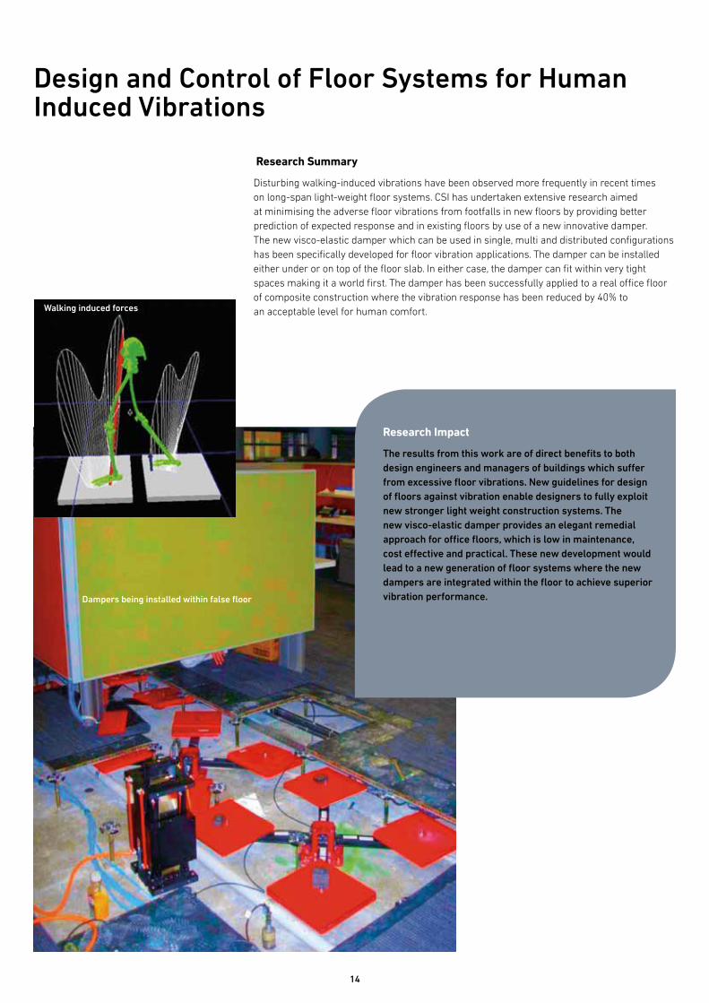
Research Summary
Disturbing walking-induced vibrations have been observed more frequently in recent times on long-span light-weight floor systems. CSI has undertaken extensive research aimed at minimising the adverse floor vibrations from footfalls in new floors by providing better prediction of expected response and in existing floors by use of a new innovative damper. The new visco-elastic damper which can be used in single, multi and distributed configurations has been specifically developed for floor vibration applications. The damper can be installed either under or on top of the floor slab. In either case, the damper can fit within very tight spaces making it a world first. The damper has been successfully applied to a real office floor of composite construction where the vibration response has been reduced by 40% to an acceptable level for human comfort.
Design and Control of Floor Systems for Human Induced Vibrations
Research Impact
The results from this work are of direct benefits to both design engineers and managers of buildings which suffer from excessive floor vibrations. New guidelines for design of floors against vibration enable designers to fully exploit new stronger light weight construction systems. The new visco-elastic damper provides an elegant remedial approach for office floors, which is low in maintenance, cost effective and practical. These new development would lead to a new generation of floor systems where the new dampers are integrated within the floor to achieve superior vibration performance.Dampers being installed within false floor
Walking induced forces

15
Research Summary
Many existing box girder bridges are presently being retrofit with fiber composite materials to achieve greater flexural, shear and torsion strength to meet the demand of today’s escalating traffic loading. The Centre for Sustainable Infrastructure at the Smart Structures Laboratory developed an innovative research program to address the issue of premature delamination of FRP materials from the concrete substrate which culminated in a novel patch anchorage system consisting of ±45º oriented bidirectional fibers. The anchored joints experienced increases in strength of 93-109 % as well as loaded end slippage of 4 to 8 times above that of the unanchored but strengthened control counterparts. This ±45º oriented bi-directional fabric configuration was successfully applied in the strengthening of the West Gate Bridge in Melbourne.
Anchorage Systems in Strengthening of Bridge Infrastructure Using Fiber Composite Materials
Research Impact
The research project falls under the National Research Priority Area of Frontier Technologies for Building and Transforming Australian Industries with the specific goal of Advanced Materials application to the Built Environment.
It was the first comprehensive study of its type in Australia and indeed in the world and the outcomes have been incorporated into major strengthening projects such as the Westgate Bridge and more recently the M80 Ring Road upgrade. The life extension of structures is important to promote sustainability practices via sustainable development of the current infrastructure.
A further benefit was the development of local advanced expertise in the field of structural retrofitting using FRP composites which provided the structural design industry the confidence needed to design and specify advanced materials (i.e. FRP) for construction applications.
Westgate Bridge, Melbourne

16
Future Development
Typical strain data contour over entire specimen area
CCD cameras mounted CCD cameras positioned approximately 3m away from test specimen
Spechle patter prior to testing
Despite the gaining popularity of FRP composites for repair and strengthening, there is still (and has always been) a severe limitation associated with premature debonding failure. Such failure is generally sudden and constitutes a severe under-utilisation of the strength of the material. Although the research conducted by CSI has made a valuable contribution to addressing such shortcomings, the test data remains limited and potential anchorage configurations remain to be investigated. Research in this field will continue to evolve in the form of further strengthening solutions, thereby increasing the efficiency of current practices in the industry.
17
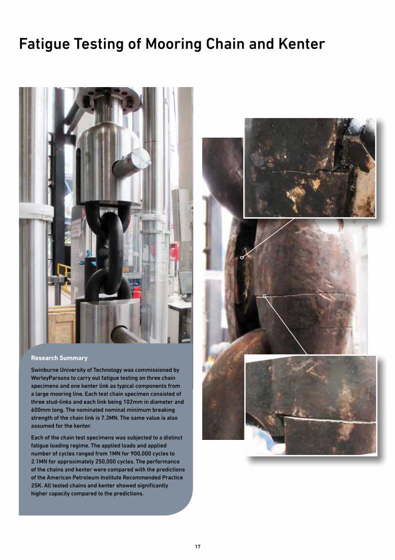
Fatigue Testing of Mooring Chain and Kenter
Research Summary
Swinburne University of Technology was commissioned by WorleyParsons to carry out fatigue testing on three chain specimens and one kenter link as typical components from a large mooring line. Each test chain specimen consisted of three stud-links and each link being 102mm in diameter and 600mm long. The nominated nominal minimum breaking strength of the chain link is 7.3MN. The same value is also assumed for the kenter.
Each of the chain test specimens was subjected to a distinct fatigue loading regime. The applied loads and applied number of cycles ranged from 1MN for 900,000 cycles to 2.1MN for approximately 250,000 cycles. The performance of the chains and kenter were compared with the predictions of the American Petroleum Institute Recommended Practice 2SK. All tested chains and kenter showed significantly higher capacity compared to the predictions.
18
Research Summary
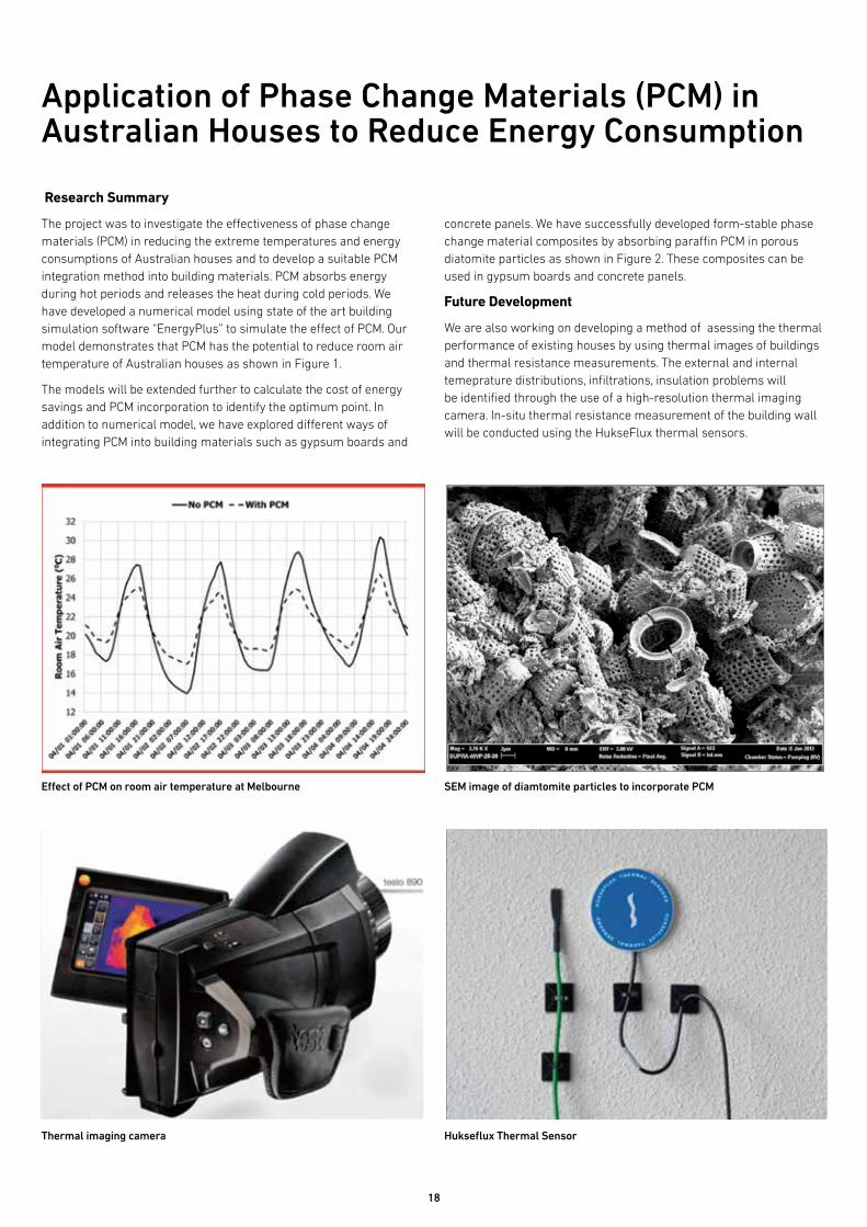
The project was to investigate the effectiveness of phase change materials (PCM) in reducing the extreme temperatures and energy consumptions of Australian houses and to develop a suitable PCM integration method into building materials. PCM absorbs energy during hot periods and releases the heat during cold periods. We have developed a numerical model using state of the art building simulation software “EnergyPlus” to simulate the effect of PCM. Our model demonstrates that PCM has the potential to reduce room air temperature of Australian houses as shown in Figure 1.
The models will be extended further to calculate the cost of energy savings and PCM incorporation to identify the optimum point. In addition to numerical model, we have explored different ways of integrating PCM into building materials such as gypsum boards and
Application of Phase Change Materials (PCM) in Australian Houses to Reduce Energy Consumption
concrete panels. We have successfully developed form-stable phase change material composites by absorbing paraffin PCM in porous diatomite particles as shown in Figure 2. These composites can be used in gypsum boards and concrete panels.
Future Development
We are also working on developing a method of asessing the thermal performance of existing houses by using thermal images of buildings and thermal resistance measurements. The external and internal temeprature distributions, infiltrations, insulation problems will be identified through the use of a high-resolution thermal imaging camera. In-situ thermal resistance measurement of the building wall will be conducted using the HukseFlux thermal sensors.
Effect of PCM on room air temperature at Melbourne
Thermal imaging camera
SEM image of diamtomite particles to incorporate PCM
Hukseflux Thermal Sensor

19

Further information
Professor Riadh Al-Mahaidi Telephone: +61 3 9214 8429 email: [email protected]
Professor Emad Gad Telephone: +61 3 9214 8210 email: [email protected]
Professor John Wilson Telephone: +61 3 9214 4820 email: [email protected]
Professor Jay Sanjayan Telephone: +61 3 9214 8034 email: [email protected]
swinburne.edu.au/science-engineering-technology
Swinburne University of Technology Melbourne, Australia
CRICOS provider code: 00111D