Smart Metering Road Map for Nepal - Asian Development Bank · (Smart Grids) and Susumu Yoneoka,...
54
ASIAN DEVELOPMENT BANK DECEMBER 2018 SMART METERING ROAD MAP FOR NEPAL
Transcript of Smart Metering Road Map for Nepal - Asian Development Bank · (Smart Grids) and Susumu Yoneoka,...

ASIAN DEVELOPMENT BANK
Smart Metering Road Map for Nepal
This smart metering road map summarizes the proposed activities and plans for the Nepal Electricity Authority on the implementation of a smart electricity grid. Prepared under the Power Transmission and Distribution Efficiency Enhancement Project in Nepal, the road map also explains the guiding principles, decision framework, and methodology used to manage the transition to new technologies.
About the Asian Development Bank
ADB is committed to achieving a prosperous, inclusive, resilient, and sustainable Asia and the Pacific, while sustaining its efforts to eradicate extreme poverty. Established in 1966, it is owned by 67 members— 48 from the region. Its main instruments for helping its developing member countries are policy dialogue, loans, equity investments, guarantees, grants, and technical assistance.
ASIAN DEVELOPMENT BANK6 ADB Avenue, Mandaluyong City1550 Metro Manila, Philippineswww.adb.org
DECEMBER 2018
SMART METERING ROAD MAP FOR NEPAL
ASIAN DEVELOPMENT BANK
SMART METERING ROAD MAP FOR NEPALDECEMBER 2018
Creative Commons Attribution 3.0 IGO license (CC BY 3.0 IGO)
© 2018 Asian Development Bank6 ADB Avenue, Mandaluyong City, 1550 Metro Manila, PhilippinesTel +63 2 632 4444; Fax +63 2 636 2444www.adb.org
Some rights reserved. Published in 2018.
ISBN 978-92-9261-468-3 (print), 978-92-9261-469-0 (electronic)Publication Stock No. TCS189790-2DOI: http://dx.doi.org/10.22617/TCS189790-2
The views expressed in this publication are those of the authors and do not necessarily reflect the views and policies of the Asian Development Bank (ADB) or its Board of Governors or the governments they represent.
ADB does not guarantee the accuracy of the data included in this publication and accepts no responsibility for any consequence of their use. The mention of specific companies or products of manufacturers does not imply that they are endorsed or recommended by ADB in preference to others of a similar nature that are not mentioned.
By making any designation of or reference to a particular territory or geographic area, or by using the term “country” in this document, ADB does not intend to make any judgments as to the legal or other status of any territory or area.
This work is available under the Creative Commons Attribution 3.0 IGO license (CC BY 3.0 IGO) https://creativecommons.org/licenses/by/3.0/igo/. By using the content of this publication, you agree to be bound by the terms of this license. For attribution, translations, adaptations, and permissions, please read the provisions and terms of use at https://www.adb.org/terms-use#openaccess.
This CC license does not apply to non-ADB copyright materials in this publication. If the material is attributed to another source, please contact the copyright owner or publisher of that source for permission to reproduce it. ADB cannot be held liable for any claims that arise as a result of your use of the material.
Please contact [email protected] if you have questions or comments with respect to content, or if you wish to obtain copyright permission for your intended use that does not fall within these terms, or for permission to use the ADB logo.
Notes:In this publication, $ refers to United States dollars.ADB recognizes “China” as the People’s Republic of China.Corrigenda to ADB publications may be found at http://www.adb.org/publications/corrigenda.On the cover: Enhancing energy infrastructure for Nepal (graphic design by Jasper Lauzon).
Printed on recycled paper
iii
Contents
Tables and Figures v
Acknowledgments vi
Abbreviations vii
Executive Summary viii
1 Background 1
2 The Power Sector in Nepal 32.1 Policy-Level Institutions 32.2 Regulatory-Level Institution 32.3 Operational-Level Institutions 42.4 Implementation-Level Institution 4
3 Drivers of Smart Metering in Nepal 53.1 Nepal Electricity Authority 53.2 Consumers 53.3 Government and Regulators 6
4 Benefits of Smart Metering 7
5 Challenges for Smart Metering in Nepal 85.1 Planning, Policy, and Regulation 85.2 Power Infrastructure 85.3 Financial Resources 85.4 Institutional Capacity 9
Contentsiv
6 Smart Metering Road Map for Nepal 106.1 Industry Readiness 106.2 Policy, Regulations, and Standards 106.3 Alignment with Legacy Infrastructure 116.4 Upgrading Business Processes for Smart Metering 116.5 Alignment of Upcoming Enterprise Resource Planning Solution with Smart Metering System 126.6 Smart Metering Rollout and Implementation Strategy 136.7 Smart Metering Rollout Plan 146.8 High-Level Smart Metering Deployment Architecture 156.9 Smart Metering as a Building Block for Smart Grids and Smart Cities 166.10 Training and Capacity Building 176.11 Formation of National Monitoring and Task Force Committee 18
7 Innovative Business Models 217.1 Comparison of Innovative Business Models 217.2 Global Best Practices on Business Models 23
8 Snapshot of Milestones in the Smart Metering Road Map 24
9 Conclusion 26
Appendixes1 Indicative Functional Requirements of Smart Meters 272 Indicative Functional Requirements of Data Concentrator Unit 363 Indicative Functional Requirements of Router and Access Point 384 Indicative Functional Requirements of Head-End System 395 Indicative Functional Requirements of Meter Data Management System 41
v
Tables and Figures
Tables1 Total Available Energy and Peak Demand in Nepal, 2011–2017 22 Key Benefits of Smart Metering 73 Smart Metering Rollout Plan 144 Comparison of Approaches to Smart Metering Deployment 165 Some Innovative Business Models 216 Comparison of Business Models 227 Mapping of Business Models with Respect to Nepal Electricity Authority Readiness 238 Milestones in the Smart Metering Road Map 24
Figures1 Total Available Energy and Peak Demand in Nepal, 2011–2017 12 Institutional Setup of the Nepal Energy Sector 43 Alignment of Upcoming Enterprise Resource Planning Solution with Smart Metering System 124 Smart Metering Deployment Architecture (Illustrative) 155 Key Characteristics of Capacity Building 176 Sample Structure of Steering Committee 18
vi
Tables, Figures, and Boxesvi
Acknowledgments
This smart metering road map is prepared under the Power Transmission and Distribution Efficiency Enhancement Project in Nepal (TA 9144-NEP) under the technical supervision of Jiwan Acharya, principal energy specialist and team leader, Energy Division (SAEN), South Asia Department; along with Pushkar Manandhar, project officer (Energy), Nepal Resident Mission (NRM). Dae Kyeong Kim, senior energy specialist (Smart Grids) and Susumu Yoneoka, energy specialist (Smart Grids) from Energy Sector Group, Sustainable Development and Climate Change Department of ADB reviewed the draft and provided useful feedback and inputs. The technical team comprising Vinit Mishra, smart meter specialist (consultant) and Hem Thukral, smart meter expert (consultant) from Ernst and Young LLP India provided substantial inputs while drafting this report with inputs from Sudhanshu Gupta, associate partner, Ernst and Young LLP India. Hannelli Austria, senior project officer and Noreen Ruanes, operations assistant, SAEN, provided support throughout the process of publishing this report. Yongping Zhai, Chief, Energy Sector Group, Priyantha Wijayatunga, director, SAEN; and Mukhtor Khamudkhanov, country director, NRM, provided the overall direction and inputs while preparing this report.
The team thanks Kul Man Ghising, managing director, Nepal Electricity Authority (NEA); Manoj Silwal, officiating deputy managing director, NEA, for their overall support, inputs and feedback throughout the process and appreciates inputs from Hara Raj Neupane, deputy managing director and other senior officials from the NEA, including Juju Shakya, Sanjay Upadhyaya, Ranju Pandey, and others from Project Management Directorate, Distribution and Consumer Services, and information technology departments of the NEA. The team is also grateful to Ministry of Energy, Water Resources and Irrigation officials for their participation and inputs during the discussion.
vii
Abbreviations
ADB – Asian Development Bank
AMI – advanced metering infrastructure
AT&C – aggregate technical and commercial
CAPEX – capital expenditure
DC – distribution center
DCU – data concentrator unit
DISCOM – distribution company
EPC – engineering, procurement, and construction
ERP – enterprise resource planning
HES – head-end system
IPP – independent power producer
IT – information technology
MDMS – meter data management system
NEA – Nepal Electricity Authority
OPEX – operational expenditure
viii
Executive Summary
This smart metering road map, prepared under the Power Transmission and Distribution Efficiency Enhancement Project in Nepal (TA 9144-NEP), summarizes the proposed activities and plans for the Nepal Electricity Authority (NEA) on its plan of implementation of a smart electricity grid, and explains the guiding principles, decision framework, and methodology used to manage the transition to new technologies.
The electricity market in Nepal faces many significant challenges due to inadequate power generation, poor distribution and transmission infrastructures resulting from years of underinvestment and delay in the sector reform causing inadequate policy and regulatory frameworks. To mitigate these challenges, the Government of Nepal is undertaking various measures by pursuing energy sector reforms; increasing investment in the sector, including prioritizing development of alternative sources of energy, and promoting energy efficiency, among others; as well as achieving demand-side management. As part of this journey, the NEA is also planning to deploy smart meters and associated information technology (IT) systems to improve its operational efficiency by establishing a transparent and real-time interface with electricity customers.
This smart metering road map for the NEA has the following objectives:
(i) Formulate a strategy for the deployment of smart meters across Nepal, together with a suitable policy and regulatory framework;
(ii) Increase the use of automation to improve grid operations;(iii) Balance electricity demand and supply via demand-side management options;(iv) Deploy telecommunication technologies that enhance the efficiency of the physical operations
involved in operating the electricity grid; and(v) Provide reliable and adequate power to all households while obtaining real-time information about
operation parameters.
The smart metering rollout program is in its early stages and will be deployed in phases across the electricity distribution network of Nepal. It is envisaged to conduct six smart metering pilot projects in six distribution centers (DCs) by September 2020, deploy 450,000 smart meters by May 2021, 3 million smart meters by May 2023, and 5 million smart meters in total by May 2025.
This program will need the support of the metering industry; strong impetus from various institutions for the formulation of policies, regulations, and standards; and synchronization with other ongoing information and communication technology and automation programs of the NEA, including the deployment of enterprise resource planning (ERP) solutions and the strengthening of the country’s transmission and distribution network. Moreover, this smart metering system will act as a foundation of a modern electricity grid and will complement the distribution automation system that would be deployed in future and would lead to a stable and efficient electricity infrastructure.

Executive Summary ix
Transition toward the smart grids will further assist the NEA in overcoming the existing and upcoming challenges confronting the Nepal power sector. A smart metering deployment architecture is described here, along with different implementation approaches in the context of possible restructuring of the distribution system of the NEA under ongoing state restructuring process with implementation of federalization. As smart metering is an evolving domain, the NEA would need to explore and consider various innovative business models for the successful implementation of the program. The scope of this road map has been limited to smart metering and functionalities such as distribution automation, home and building automation, feasibility of various communication technologies, and interoperability would also need to be studied. The NEA may conduct a detailed study on these areas at a later stage.

1
1 Background
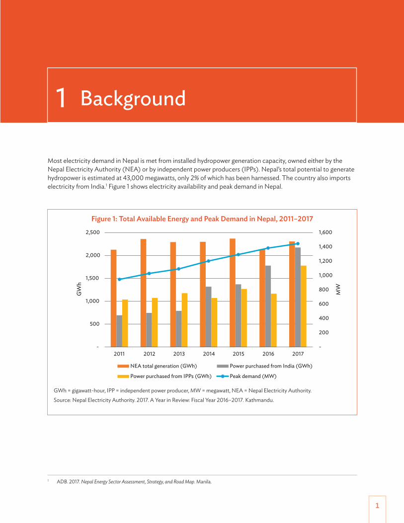
Most electricity demand in Nepal is met from installed hydropower generation capacity, owned either by the Nepal Electricity Authority (NEA) or by independent power producers (IPPs). Nepal’s total potential to generate hydropower is estimated at 43,000 megawatts, only 2% of which has been harnessed. The country also imports electricity from India.1 Figure 1 shows electricity availability and peak demand in Nepal.
1 ADB. 2017. Nepal Energy Sector Assessment, Strategy, and Road Map. Manila.
Figure 1: Total Available Energy and Peak Demand in Nepal, 2011–2017
-
200
400
600
800
1,000
1,200
1,400
1,600
-
500
1,000
1,500
2,000
2,500
2011 2012 2013 2014 2015 2016 2017
MW
GW
h
NEA total generation (GWh) Power purchased from India (GWh)
Power purchased from IPPs (GWh) Peak demand (MW)
GWh = gigawatt-hour, IPP = independent power producer, MW = megawatt, NEA = Nepal Electricity Authority.
Source: Nepal Electricity Authority. 2017. A Year in Review: Fiscal Year 2016–2017. Kathmandu.
Smart Metering Road Map for Nepal2
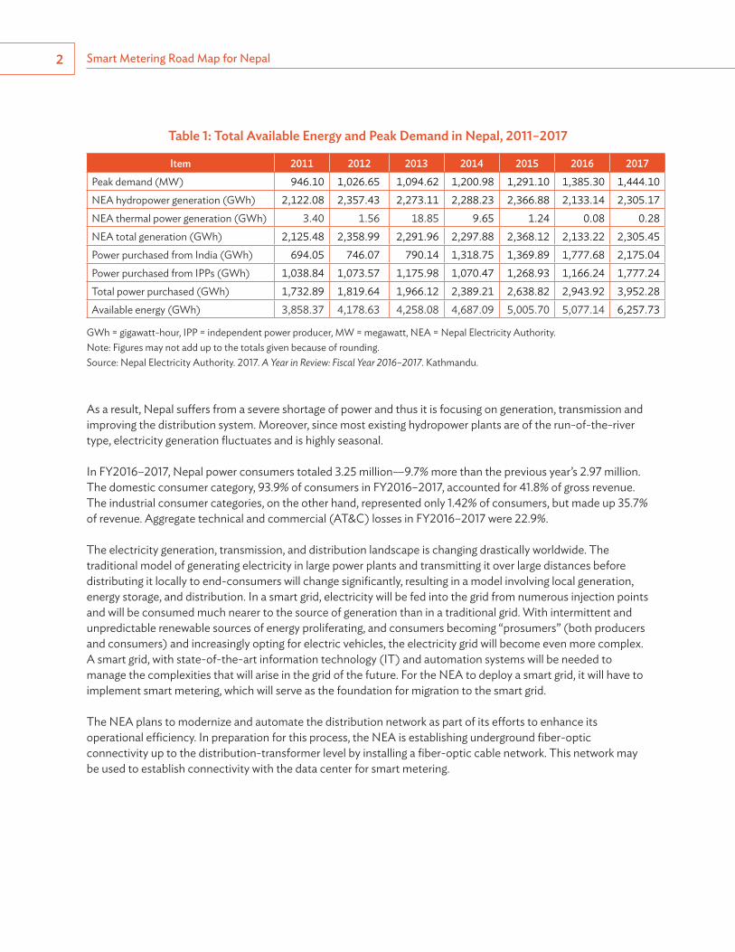
Table 1: Total Available Energy and Peak Demand in Nepal, 2011–2017
Item 2011 2012 2013 2014 2015 2016 2017Peak demand (MW) 946.10 1,026.65 1,094.62 1,200.98 1,291.10 1,385.30 1,444.10NEA hydropower generation (GWh) 2,122.08 2,357.43 2,273.11 2,288.23 2,366.88 2,133.14 2,305.17NEA thermal power generation (GWh) 3.40 1.56 18.85 9.65 1.24 0.08 0.28NEA total generation (GWh) 2,125.48 2,358.99 2,291.96 2,297.88 2,368.12 2,133.22 2,305.45Power purchased from India (GWh) 694.05 746.07 790.14 1,318.75 1,369.89 1,777.68 2,175.04Power purchased from IPPs (GWh) 1,038.84 1,073.57 1,175.98 1,070.47 1,268.93 1,166.24 1,777.24Total power purchased (GWh) 1,732.89 1,819.64 1,966.12 2,389.21 2,638.82 2,943.92 3,952.28Available energy (GWh) 3,858.37 4,178.63 4,258.08 4,687.09 5,005.70 5,077.14 6,257.73
GWh = gigawatt-hour, IPP = independent power producer, MW = megawatt, NEA = Nepal Electricity Authority.Note: Figures may not add up to the totals given because of rounding.Source: Nepal Electricity Authority. 2017. A Year in Review: Fiscal Year 2016–2017. Kathmandu.
As a result, Nepal suffers from a severe shortage of power and thus it is focusing on generation, transmission and improving the distribution system. Moreover, since most existing hydropower plants are of the run-of-the-river type, electricity generation fluctuates and is highly seasonal.
In FY2016–2017, Nepal power consumers totaled 3.25 million—9.7% more than the previous year’s 2.97 million. The domestic consumer category, 93.9% of consumers in FY2016–2017, accounted for 41.8% of gross revenue. The industrial consumer categories, on the other hand, represented only 1.42% of consumers, but made up 35.7% of revenue. Aggregate technical and commercial (AT&C) losses in FY2016–2017 were 22.9%.
The electricity generation, transmission, and distribution landscape is changing drastically worldwide. The traditional model of generating electricity in large power plants and transmitting it over large distances before distributing it locally to end-consumers will change significantly, resulting in a model involving local generation, energy storage, and distribution. In a smart grid, electricity will be fed into the grid from numerous injection points and will be consumed much nearer to the source of generation than in a traditional grid. With intermittent and unpredictable renewable sources of energy proliferating, and consumers becoming “prosumers” (both producers and consumers) and increasingly opting for electric vehicles, the electricity grid will become even more complex. A smart grid, with state-of-the-art information technology (IT) and automation systems will be needed to manage the complexities that will arise in the grid of the future. For the NEA to deploy a smart grid, it will have to implement smart metering, which will serve as the foundation for migration to the smart grid.
The NEA plans to modernize and automate the distribution network as part of its efforts to enhance its operational efficiency. In preparation for this process, the NEA is establishing underground fiber-optic connectivity up to the distribution-transformer level by installing a fiber-optic cable network. This network may be used to establish connectivity with the data center for smart metering.
3
Nepal’s power sector is dominated by the NEA, a utility established in August 1985 under the Nepal Electricity Authority Act of 1984, following the merger of the Electricity Department, incumbent electricity development boards, and the Nepal Electricity Corporation (NEC).
The NEA operates under the Ministry of Energy, Water Resources and Irrigation, which has overall responsibility for all private and public activities related to electricity supply in the country.2
The Government of Nepal has established the current institutional arrangements in the power sector at four levels, namely, policy, regulatory, operational, and implementation (footnote 1).
2.1 Policy-Level InstitutionsThe Ministry of Energy, Water Resources and Irrigation draws up policies for the power sector, develops water resources, and exercises oversight and regulation of the NEA and private power development.
The National Planning Commission plans and monitors the government’s periodic investment program involving several sectors.
The Water and Energy Commission advises the government on policies related to technical, legal, environmental, financial, and institutional matters with respect to water resources.
The National Water Resources Development Council guides the government on strategic issues and policy matters related to integrated water resource development.
The Environment Protection Council develops policies and formulates regulations and guidelines related to the environment and environmental protection.
2.2 Regulatory-Level InstitutionThe Electricity Regulatory Commission is an independent regulatory body is being operationalized.
2 United States Agency for International Development. South Asia Regional Initiative/Energy (SARI/EI) Program. https://sari-energy.org/oldsite/PageFiles/Countries/Nepal_Energy_detail.html.
2 The Power Sector in Nepal

Smart Metering Road Map for Nepal4
2.3 Operational-Level InstitutionsThe Nepal Electricity Authority (NEA) is a public sector utility that generates, transmits, and distributes electricity throughout the country. Another NEA responsibility is coordinating the exchange of electricity with India. The NEA also acts as the single buyer of electricity from private (independent) power producers.
The Alternative Energy Promotion Centre (AEPC) is a government institution under the Ministry of Energy, Water Resources and Irrigation with the objective of developing and promoting renewable/alternative energy technologies in Nepal.
The Butwal Power Company is also undertaking power generation and distribution in Nepal.
Independent power producers (IPPs) develop private power plants and generate electricity.
2.4 Implementation-Level InstitutionThe Department of Electricity Development is a government-owned body responsible for implementing and promoting the government’s policies related to power production. Figure 2 presents the institutional setup of the Nepal energy sector.
Figure 2: Institutional Setup of the Nepal Energy Sector
Government of Nepal
Nepal ElectricityAuthority
Generation
Transmission
Distribution
Power trading
Department ofElectricity Development
Electricity RegulatoryCommission
Independent powerproducers
G
T
D
IFIs
Ministry of Energy, Water Resources
and Irrigation
Ministry of Forests and Environment; National Planning Commission;
Water and Energy Commission
ADB, World Bank, JICA, KfW, EIB and others
ADB = Asian Development Bank, AIIB = Asian Infrastructure Investment Bank, EIB = European Investment Bank, IFI = international financial institution, JICA = Japan International Cooperation Agency.
Source: ADB. 2017. Nepal Energy Sector Assessment, Strategy, and Road Map. Manila.
5
This smart metering road map has been prepared to enhance the operational efficiency of the NEA, improving the quality of the power supply through near-real-time granular readings provided by smart meters, enhancing the satisfaction of consumers and increasing consumer participation. However, the benefits of smart metering is not limited only to the NEA and go beyond various stakeholders as listed below.3
3.1 Nepal Electricity Authority(i) Reduced AT&C losses, as well as improved collection efficiency;(ii) Peak load management (including provision of various options, from control of load of consumer
to incentives for consumers); (iii) Lower cost of purchased power;(iv) Improved asset management;(v) Enhanced grid visibility;(vi) Self-healing power grid;(vii) Renewable energy integration (including rooftop solar systems); and (viii) Bulk-sourced smart meters, for economies of scale.
3.2 Consumers (i) Regular accurate view of electricity consumption;(ii) More reliable supply of electricity to all consumers, leading to reduced power cuts, and less need
for diesel generator sets and inverters;(iii) Higher-quality electricity supply, reducing the need for voltage stabilizers;(iv) User-friendly and transparent interface with utilities;(v) More electricity supply options for consumers (including renewables);(vi) Enabled “prosumers” (producers and consumers of electricity); (vii) Opportunities to save money by shifting demand from peak to off-peak periods;(viii) Value-added services for smart homes; and(ix) Smart premises for large consumers.
3 Ministry of Power, India. 2013. Smart Grid Vision and Road Map for India. Prepared with the support of the India Smart Grid Task Force and the India Smart Grid Forum. New Delhi. http://www.indiasmartgrid.org/reports/Smart%20Grid%20Vision%20and%20Roadmap%20for%20India.pdf.
3 Drivers of Smart Metering in Nepal
Smart Metering Road Map for Nepal6
3.3 Government and Regulators(i) Satisfied consumers;(ii) Financially sound utilities;(iii) Capability to modernize the power grid without raising tariffs;(iv) More accessible lifeline power;(v) Optimized use of electricity;(vi) Improved transmission and distribution network through more visible power flow at the granular
level;(vii) Demand management; and (viii) Lower emission intensity.

7
Smart metering will provide benefits to all stakeholders including the NEA, electricity consumers, and the general public. The benefits include, among others, enabling the NEA to identify and reduce AT&C losses, bring down the meter reading and associated cost, reduce the peak power purchase cost with more accurate load estimates, save money from remote connection/disconnection and detect outages faster via last-gasp and first-breath notifications, reduce the distribution transformer failure rate, identify power quality parameters, reduce the load on consumer care centers, and provide regulators with an accurate set of data.
Smart metering also provides intangible benefits to consumers through faster recovery from power outages, error-free bills, the ability to keep track of electricity consumption and thus save money, the ability to monitor and control appliances at homes and offices (albeit with additional infrastructure for home and building automation), a reduced carbon footprint, and the creation of a platform for several value-added services, such as leased backbone (last-mile) communication networks, and insurance for home appliances. Smart metering thus offers profound benefits for all stakeholders, hence the need to fast-track deployment. Key benefits offered by smart metering to the NEA, consumers, and the general public are summarized in Table 2.
Table 2: Key Benefits of Smart Metering
NEA Consumers General PublicReal-time energy accounting, thereby reducing AT&C lossesReduction in labor costReduction in peak power purchase cost via better estimation of loadsReduction in connection/disconnection costFaster detection of defective metersFaster detection of outages via last-gasp and first-breath notificationsIdentification of phase imbalanceReduction in time taken and in human error during meter reading and bill generationReduction in distribution transformer failure ratePower quality measurementReduced load on call centers and consumer care centers Reduced NEA debt, leading to better cash flows for the generation company
Faster recovery from outagesError-free bills Savings on electricity bills via time-of-use tariffsAbility to monitor electricity consumption and thus save moneyAbility to manage and control appliances at homes and offices (with additional home and building automation tools)
Reduction in carbon footprint via reduced patrolling for outage detection, meter reading, connection/reconnection and others.Platform for other value-added services
AT&C = aggregate technical and commercial, NEA = Nepal Electricity Authority.Source: India Smart Grid Forum. 2016. AMI Rollout Strategy and Cost-Benefit Analysis for India. ISGF White Paper. http://www.indiasmartgrid.org/reports/AMI Roll-Out Strategy and Cost-Benefit Analysis for India FINAL(1).pdf
4 Benefits of Smart Metering
8
5 Challenges for Smart Metering in Nepal
For the successful rollout of the smart metering program in Nepal, some core issues, constraints, and opportunities need special attention.
5.1 Planning, Policy, and RegulationThe global energy sector is undergoing fundamental change with the introduction of technology innovations and new services. Existing regulatory and market arrangements must evolve to protect the interests of consumers and enable them to benefit from the innovations. However, Nepal has no national energy strategy and weak regulatory frameworks. The existing energy policy objectives were formulated as general 3-year plans by the central planning entity, the National Planning Commission.
For the efficient rollout of advanced technology programs, the NEA and other stakeholders should see to it that a regulatory framework for promoting innovation is established, that it supports transformation to a low-carbon energy ecosystem, and that it delivers sustainable, resilient, and affordable services to consumers.
5.2 Power InfrastructureNepal has an inadequate electricity infrastructure. There are significant deficiencies in transmission and distribution, and losses, attributed to poor operation and maintenance and underperformance of aging assets, are high.
These shortcomings could hinder the rollout of smart metering by limiting the technologies and methodologies that vendors across Nepal might adopt during the rollout.
5.3 Financial ResourcesThe Government of Nepal has major financing responsibilities in many other sectors and might have limited resources to develop Nepal’s power sector infrastructure on its own. To ensure the full development of the power sector and leverage the investments made by the government, particularly where implementing advanced technologies like smart metering and smart grids is concerned, innovative business model using public–private partnership (PPP) could also be explored.

Challenges for Smart Metering in Nepal 9
5.4 Institutional CapacityThe NEA has dominated the electricity sector since its establishment in 1985 and is responsible for all electricity supply systems planning, construction, and operation.
However, its operational and financial performance must significantly improve, especially in the area of high-end technology, cybersecurity, and others. To implement advanced technologies like smart metering, the governance structure must be streamlined and capacity must be strengthened through substantive reform.
10
6.1 Industry ReadinessNepal needs to develop a metering industry and subsequently transform into a large-scale supplier of smart meters at affordable cost. Having manufacturing facilities in the country will also create jobs and develop a skilled workforce. Adequate opportunities must be provided to micro, small, and medium-sized enterprises and start-ups to supply smart meters and its enabling technologies. There is a need to support such companies to inject competition in terms of quality and cost, and subsequently develop a larger pool of smart meter manufacturers in Nepal.
6.2 Policy, Regulations, and Standards(i) The NEA formulates effective consumer outreach programs, to encourage the active participation
of consumers in smart metering implementation, by May 2019; (ii) The NEA finalizes frameworks for cybersecurity audit and assessment, for use of smart meters,
by December 2019;(iii) The Electricity Regulatory Commission, once operationalized, provides the necessary approvals
and guidelines, for smart meter use, including time-of-use tariffs, by December 2019;(iv) The Ministry of Energy, Water Resources and Irrigation sets up the Electricity Regulatory
Commission, with defined roles and responsibilities, by December 2019;(v) The Electricity Regulatory Commission formulates regulations for the remote connection and
disconnection of electricity at a particular consumer’s premises, by May 2020;(vi) The Nepal Telecommunications Authority (NTA) allocates sufficient spectrum in the
sub-gigahertz frequency bands for machine-to-machine and other Internet of Things (IoT) applications in the smart metering, smart grid, and smart city domains, by December 2019; and
(vii) The Bureau of Standards, under the Ministry of Industry, formulates national standards and specifications for smart meters and functionalities of the advanced metering infrastructure (AMI) by May 2019. The specifications will define standardized interfaces between AMI and other utility applications.
6 Smart Metering Road Map for Nepal
Smart Metering Road Map for Nepal 11
6.3 Alignment with Legacy InfrastructureTo align the existing legacy power sector infrastructure with the upcoming smart metering solution, the following activities may be required:
(i) Adoption of the most suitable technology and cost-effective platform for the rollout of the smart metering solution consistently across Kathmandu Valley and Nepal, e.g., the use of radio frequency (RF)–based or General Packet Radio Service (GPRS)–based smart meters instead of power line carrier (PLC) communication, to overcome the shortcomings of the existing distribution network;
(ii) Integration of smart metering with the existing billing system and the geographic information system (GIS), as and when smart metering is implemented in the respective DCs; and
(iii) Preparation and implementation of a master plan for upgrading distribution assets, by December 2019.
6.4 Upgrading Business Processes for Smart MeteringSmart metering would require the NEA to upgrade its business processes to account for the new services and data flows between new and legacy systems. All processes, including meter reading, connection/disconnection, firmware upgrade, and meter maintenance, would need to be defined in detail to enable a successful rollout of smart metering.
The NEA should take the following steps (indicative and nonexhaustive) by May 2019:
(i) The NEA enrolls consumers in a smart metering–related service or product;(ii) The NEA updates consumers’ account information to maintain the accuracy of records;(iii) The NEA provides consumption and tariff data to consumers;(iv) The NEA captures consumption data through remote meter reading;(v) The NEA carries out remote connection, disconnection, and reconnection of meters;(vi) Meters transmit events data to NEA servers;(vii) The NEA generates bills to be issued to consumers;(viii) Consumers opt for the prepayment service and the NEA configures the smart metering system to
provide the service; (ix) Consumers prepay for electricity service;(x) The NEA installs meters to enable smart metering;(xi) The NEA upgrades firmware remotely;(xii) The NEA conducts reactive and proactive maintenance of the smart metering system;(xiii) The NEA activates disaster recovery procedures to maintain business continuity in case of system
failure;(xiv) The NEA synchronizes smart metering data to maintain the accuracy of records; and(xv) The NEA implements net metering and gross metering.
Smart Metering Road Map for Nepal12
Indicative functional requirements of smart meters are mentioned in Appendix 1, data concentrator units (DCUs) in Appendix 2, routers and access points in Appendix 3, head-end systems (HESs) in Appendix 4, and meter data management systems (MDMSs) in Appendix 5.
6.5 Alignment of Upcoming Enterprise Resource Planning Solution with Smart Metering System
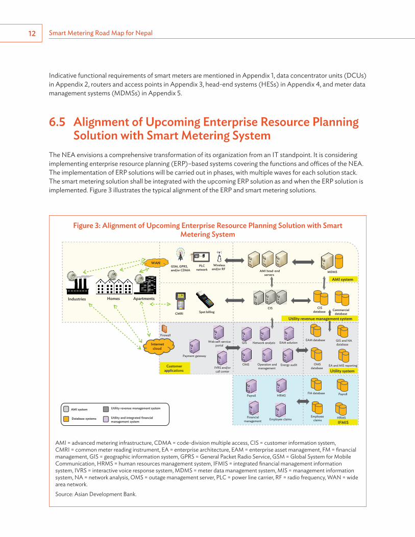
The NEA envisions a comprehensive transformation of its organization from an IT standpoint. It is considering implementing enterprise resource planning (ERP)–based systems covering the functions and offi ces of the NEA. The implementation of ERP solutions will be carried out in phases, with multiple waves for each solution stack. The smart metering solution shall be integrated with the upcoming ERP solution as and when the ERP solution is implemented. Figure 3 illustrates the typical alignment of the ERP and smart metering solutions.
Figure 3: Alignment of Upcoming Enterprise Resource Planning Solution with Smart Metering System
HomesIndustries Apartments
Wirelessand/or RF AMI head -end
serversMDMS
CIS CISdatabase Commercial
databaseCMRI Spot billing
GIS Network analysis
Payroll
EAM database
OMSdatabase
GIS and NAdatabase
HRMS
OMS Operation andmanagement
Employee claimsFinancialmanagement
EAM solution
Energy audit
FM database Payroll
Employeeclaims
EA and MIS reporting
HRMS
WAN
AMI system
Utility revenue management system
Payment gateway
IVRS and/orcall center
Internetcloud
Customerapplications Utility system
IFMIS
Utility revenue management system
Utility and integrated financialmanagement system
AMI system
Database systems
Firewall
Web self-serviceportal
GSM, GPRS, and/or CDMA
PLCnetwork
AMI = advanced metering infrastructure, CDMA = code-division multiple access, CIS = customer information system, CMRI = common meter reading instrument, EA = enterprise architecture, EAM = enterprise asset management, FM = fi nancial management, GIS = geographic information system, GPRS = General Packet Radio Service, GSM = Global System for Mobile Communication, HRMS = human resources management system, IFMIS = integrated fi nancial management information system, IVRS = interactive voice response system, MDMS = meter data management system, MIS = management information system, NA = network analysis, OMS = outage management server, PLC = power line carrier, RF = radio frequency, WAN = wide area network.
Source: Asian Development Bank.
Smart Metering Road Map for Nepal 13
The ERP solution stack and smart metering solution are enterprise packages for a power utility, which depends on seamless operations and consumer billing. For that reason, these packages will be interdependent for the performance of day-to-day business transactions.
The upcoming ERP solution must therefore be aligned with the smart metering solution, to support the smart metering program and serve as its core backbone. The implementation of these two systems in sync will require the following activities:
(i) Rolling out the ERP solution in parallel or in sync with the smart metering solution;(ii) Stabilizing the billing solution;(iii) Streamlining core business processes;(iv) Establishing a reporting framework (energy audit, AT&C losses, and others);(v) Using the smart metering feature (connect/disconnect, net metering, and others) for ERP data;(vi) Optimizing the use of implemented systems;(vii) Achieving end-to-end integration of systems and business processes;(viii) Optimizing productivity and consumer services; and(ix) Optimizing cost and efforts.
6.6 Smart Metering Rollout and Implementation Strategy Smart metering rollout strategy. Smart meters can be deployed either for specific consumers or for all consumers on the same feeder. A major drawback of deploying smart meters only for specific consumers on a feeder is that real-time energy auditing cannot be done. Another disadvantage is that creating a communications network for the last mile will be expensive as the communicating nodes will be far apart. Additional devices might be required to set up a reliable last-mile communications link.
Deploying smart meters for all consumers on entire DCs will therefore have significant advantages, such as the potential to reduce network losses and substantially lower the cost of setting up a last-mile communication network when the entire feeder is covered under the smart metering regime. The full benefits of smart metering can thus be realized only when smart meters are installed for all consumers on entire DCs. All smart metering deployments occurring after December 2018 shall adhere to this rollout strategy.
Smart metering implementation strategy. The success of the smart metering project would require synergies from all key stakeholders. To ensure the success and effectiveness of the smart metering rollout, the NEA shall undertake the following activities:
(i) Provide the implementing agency with a database of consumers and assets, including regular updates;
(ii) Cooperate with the implementing agency during data validation;(iii) Support a consumer awareness campaign;(iv) Arrange or provide all kinds of clearances, such as statutory clearances and work permits, as well as
regulatory support for the implementation of smart metering projects;(v) Conduct a preaudit of the available data in collaboration with the implementing agency;
Smart Metering Road Map for Nepal14
(vi) Ensure safe and timely access to all locations where smart meters and supporting equipment are installed;
(vii) Participate in and subsequently approve the type or design test, factory acceptance test and site acceptance test; and
(viii) Assign the required staff and empower them with the requisite authority to complete the desired tasks.
All smart metering deployments occurring after December 2018 shall adhere to this implementation strategy.
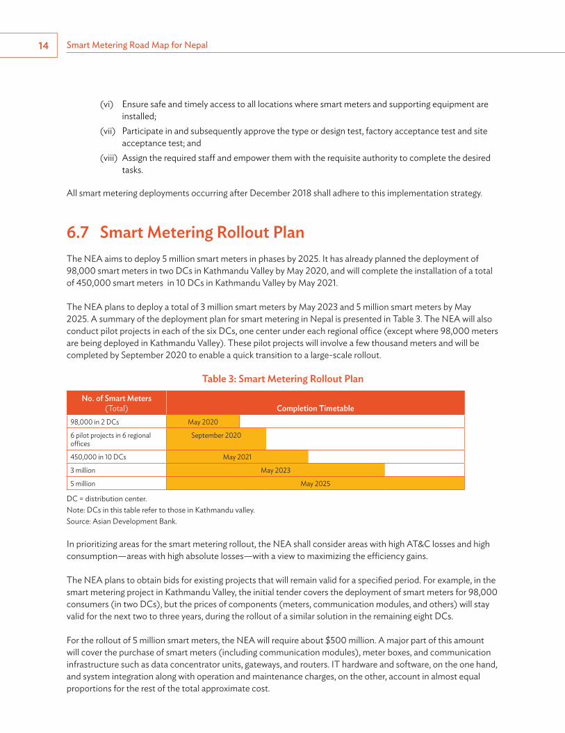
6.7 Smart Metering Rollout Plan The NEA aims to deploy 5 million smart meters in phases by 2025. It has already planned the deployment of 98,000 smart meters in two DCs in Kathmandu Valley by May 2020, and will complete the installation of a total of 450,000 smart meters in 10 DCs in Kathmandu Valley by May 2021.
The NEA plans to deploy a total of 3 million smart meters by May 2023 and 5 million smart meters by May 2025. A summary of the deployment plan for smart metering in Nepal is presented in Table 3. The NEA will also conduct pilot projects in each of the six DCs, one center under each regional office (except where 98,000 meters are being deployed in Kathmandu Valley). These pilot projects will involve a few thousand meters and will be completed by September 2020 to enable a quick transition to a large-scale rollout.
Table 3: Smart Metering Rollout Plan
No. of Smart Meters (Total) Completion Timetable
98,000 in 2 DCs May 2020
6 pilot projects in 6 regional offices
September 2020
450,000 in 10 DCs May 2021
3 million May 2023
5 million May 2025
DC = distribution center.Note: DCs in this table refer to those in Kathmandu valley.Source: Asian Development Bank.
In prioritizing areas for the smart metering rollout, the NEA shall consider areas with high AT&C losses and high consumption—areas with high absolute losses—with a view to maximizing the efficiency gains.
The NEA plans to obtain bids for existing projects that will remain valid for a specified period. For example, in the smart metering project in Kathmandu Valley, the initial tender covers the deployment of smart meters for 98,000 consumers (in two DCs), but the prices of components (meters, communication modules, and others) will stay valid for the next two to three years, during the rollout of a similar solution in the remaining eight DCs.
For the rollout of 5 million smart meters, the NEA will require about $500 million. A major part of this amount will cover the purchase of smart meters (including communication modules), meter boxes, and communication infrastructure such as data concentrator units, gateways, and routers. IT hardware and software, on the one hand, and system integration along with operation and maintenance charges, on the other, account in almost equal proportions for the rest of the total approximate cost.
Smart Metering Road Map for Nepal 15
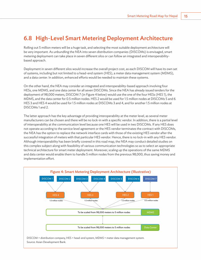
6.8 High-Level Smart Metering Deployment ArchitectureRolling out 5 million meters will be a huge task, and selecting the most suitable deployment architecture will be very important. As unbundling the NEA into seven distribution companies (DISCOMs) is envisaged, smart metering deployment can take place in seven different silos or can follow an integrated and interoperability-based approach.
Deployment in seven different silos would increase the overall project cost, as each DISCOM will have its own set of systems, including but not limited to a head-end system (HES), a meter data management system (MDMS), and a data center. In addition, enhanced efforts would be needed to maintain these systems.
On the other hand, the NEA may consider an integrated and interoperability-based approach involving four HESs, one MDMS, and one data center for all seven DISCOMs. Since the NEA has already issued tenders for the deployment of 98,000 meters, DISCOM 7 (in Figure 4 below) would use the one of the four HESs (HES 1), the MDMS, and the data center for 0.5 million nodes. HES 2 would be used for 1.5 million nodes at DISCOMs 5 and 6. HES 3 and HES 4 would be used for 1.5 million nodes at DISCOMs 3 and 4, and for another 1.5 million nodes at DISCOMs 1 and 2.
The latter approach has the key advantage of providing interoperability at the meter level, as several meter manufacturers can be chosen and there will be no lock-in with a specific vendor. In addition, there is a partial level of interoperability at the communication level because one HES will be used in two DISCOMs. If any HES does not operate according to the service level agreement or the HES vendor terminates the contract with DISCOMs, the NEA has the option to replace the network interface cards with those of the existing HES vendor after the successful integration of meters with that particular HES vendor. Hence, there is no lock-in with any HES vendor. Although interoperability has been briefly covered in this road map, the NEA may conduct detailed studies on this complex subject along with feasibility of various communication technologies so as to select an appropriate technical architecture for smart meter deployment. Moreover, scaling up the operations of the same MDMS and data center would enable them to handle 5 million nodes from the previous 98,000, thus saving money and implementation effort.
Figure 4: Smart Metering Deployment Architecture (Illustrative)
To be scaled from 98,000 meters to 5 million nodes
DISCOM 1 DISCOM 2 DISCOM 3 DISCOM 4 DISCOM 5 DISCOM 6 DISCOM 7
HES 4 HES 3 HES 2 HES 1
MDMS
To be scaled from 98,000 meters to 5 million nodes Data Center
0.5 million nodes1.5 million nodes1.5 million nodes1.5 million nodes
DISCOM = distribution company, HES = head-end system, MDMS = meter data management system.Source: Asian Development Bank.
Smart Metering Road Map for Nepal16
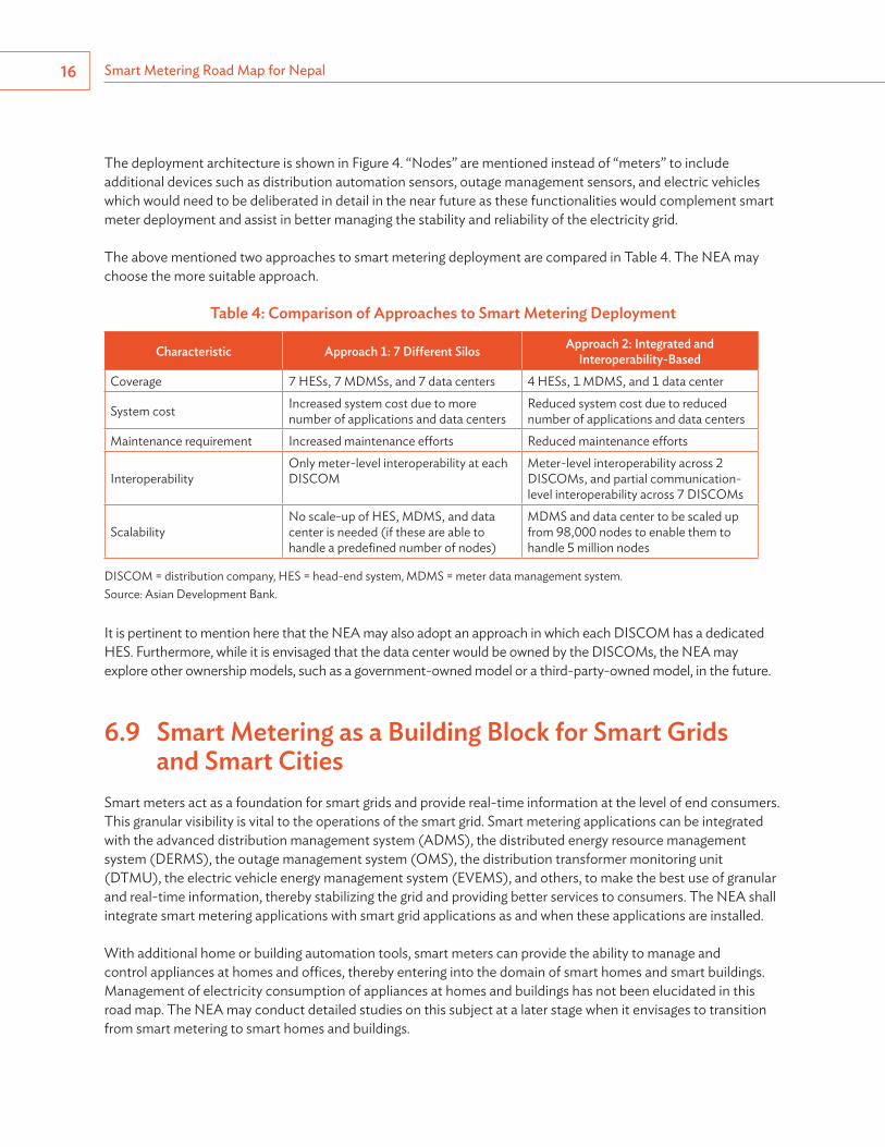
The deployment architecture is shown in Figure 4. “Nodes” are mentioned instead of “meters” to include additional devices such as distribution automation sensors, outage management sensors, and electric vehicles which would need to be deliberated in detail in the near future as these functionalities would complement smart meter deployment and assist in better managing the stability and reliability of the electricity grid.
The above mentioned two approaches to smart metering deployment are compared in Table 4. The NEA may choose the more suitable approach.
Table 4: Comparison of Approaches to Smart Metering Deployment
Characteristic Approach 1: 7 Different Silos Approach 2: Integrated and Interoperability-Based
Coverage 7 HESs, 7 MDMSs, and 7 data centers 4 HESs, 1 MDMS, and 1 data center
System cost Increased system cost due to more number of applications and data centers
Reduced system cost due to reduced number of applications and data centers
Maintenance requirement Increased maintenance efforts Reduced maintenance efforts
InteroperabilityOnly meter-level interoperability at each DISCOM
Meter-level interoperability across 2 DISCOMs, and partial communication-level interoperability across 7 DISCOMs
ScalabilityNo scale-up of HES, MDMS, and data center is needed (if these are able to handle a predefined number of nodes)
MDMS and data center to be scaled up from 98,000 nodes to enable them to handle 5 million nodes
DISCOM = distribution company, HES = head-end system, MDMS = meter data management system.Source: Asian Development Bank.
It is pertinent to mention here that the NEA may also adopt an approach in which each DISCOM has a dedicated HES. Furthermore, while it is envisaged that the data center would be owned by the DISCOMs, the NEA may explore other ownership models, such as a government-owned model or a third-party-owned model, in the future.
6.9 Smart Metering as a Building Block for Smart Grids and Smart Cities
Smart meters act as a foundation for smart grids and provide real-time information at the level of end consumers. This granular visibility is vital to the operations of the smart grid. Smart metering applications can be integrated with the advanced distribution management system (ADMS), the distributed energy resource management system (DERMS), the outage management system (OMS), the distribution transformer monitoring unit (DTMU), the electric vehicle energy management system (EVEMS), and others, to make the best use of granular and real-time information, thereby stabilizing the grid and providing better services to consumers. The NEA shall integrate smart metering applications with smart grid applications as and when these applications are installed.
With additional home or building automation tools, smart meters can provide the ability to manage and control appliances at homes and offices, thereby entering into the domain of smart homes and smart buildings. Management of electricity consumption of appliances at homes and buildings has not been elucidated in this road map. The NEA may conduct detailed studies on this subject at a later stage when it envisages to transition from smart metering to smart homes and buildings.

Smart Metering Road Map for Nepal 17
In addition, with the advent of advanced communication technologies, the last-mile connectivity deployed for smart metering can be used for distribution automation, demand response, electric vehicles, distributed energy resources, street lights, home area networks, weather sensors, traffic lights, surveillance, and others. Hence, smart metering can be used as anchor infrastructure for smart grids and smart cities. The NEA shall make the transition from smart meters to smart cities as and when the industry is mature and a business case can be made for such a move by the appropriate ministry or department of the Government of Nepal.
6.10 Training and Capacity Building Training and capacity building is a process that focuses on enhancing the skills, knowledge, and social capabilities available to individuals, including social and political systems. With respect to smart metering, Nepal will have to develop capability in areas such as metering, communication technologies for smart metering, IT applications (such as head-end and meter data management systems and analytics), system integration, and others. The NEA shall prepare a training and capacity-building plan by December 2019.
Key characteristics of the proposed capacity building are shown in Figure 5. These include (but are not limited to) the following:
(i) Performance capacity development. Development of the tools, equipment, consumables, and others to do the job;
(ii) Personal capacity development. Development of sufficiently knowledgeable, skilled, and confidently performing human resources and teams;
(iii) Workload capacity development. Development of onboard staff and team members with enough skills and ability to cope with and execute the workload;
(iv) Supervisory capacity development. Development of a reporting and monitoring system for clear accountability, with linked effective incentives.
Figure 5: Key Characteristics of Capacity Building
Structural capacity
Individual
Institutional
Structures, systems, and roles
Sta� andinfrastructure
Skills
Tools
Systems capacity
Rolecapacity
Performance capacity
Personal capacity
Workloadcapacity
Facilitycapacity
Supervisorycapacity
Support servicecapacity
Source: C. Potter and R. Brough. 2004. Systemic Capacity Building: A Hierarchy of Needs. Health Policy and Planning. Oxford University Press. pp. 336–345.

Smart Metering Road Map for Nepal18
(v) Facility development. Development of suitable staffed (in terms of both quality and quantity) training centers of sufficient size;
(vi) System capacity development. Organization of decision-making forums, intersectoral discussions, and corporate decision making to monitor account performance and keep records; and
(vii) Support capacity development. Development of institutions like laboratories, training institutions, engineering institutes, supply organizations, administrative staff, research facilities, and quality control services.
6.11 Formation of National Monitoring and Task Force Committee
There is a need for effective monitoring of all programs, and for well-defined roles and responsibilities. It is recommended that a National Monitoring Task Force Committee or Steering Committee involving major electricity stakeholders be formed by May 2019, with responsibility for the following:4
(i) Developing an implementation plan for smart metering and the smart grid, including a strong focus on energy efficiency and alternative sources of energy;
(ii) Developing recommendations for upgrades in policy, regulatory, and standardization frameworks for smart metering and the smart grid; and
(iii) Monitoring the progress of smart metering and smart grid implementation, conducting a cost–benefit analysis, and proposing corrective actions if the desired benefits are not realized.
A sample structure for the Steering Committee is shown in Figure 6.
4 Electricity and Co-Generation Regulatory Authority. 2013. Smart Metering and Smart Grid Strategy for the Kingdom of Saudi Arabia. http://www.ecra.gov.sa/enus/ECRAStudies/Documents/Smart%20Metering%20and%20Smart%20Grids%20Strategy.pdf.
Figure 6: Sample Structure of Steering Committee
National Monitoring and Task Force Committee Technical working groups
Government Agencies• National Planning
Commission• Water and Energy
Commission• Electricity Regulatory
Commission• Department of Electricity
Development• Nepal Telecommunications
Authority • Nepal Electricity Authority
Industry/Telecommunications
• Funding agencies (Asian Development Bank, World Bank and others)
• Independent power producers
Customer Representatives
• Consumer groups• Complaints Committee
Academic Institutions• Universities• Research institutes
Source: Asian Development Bank and Nepal Electricity Authority.
Smart Metering Road Map for Nepal 19
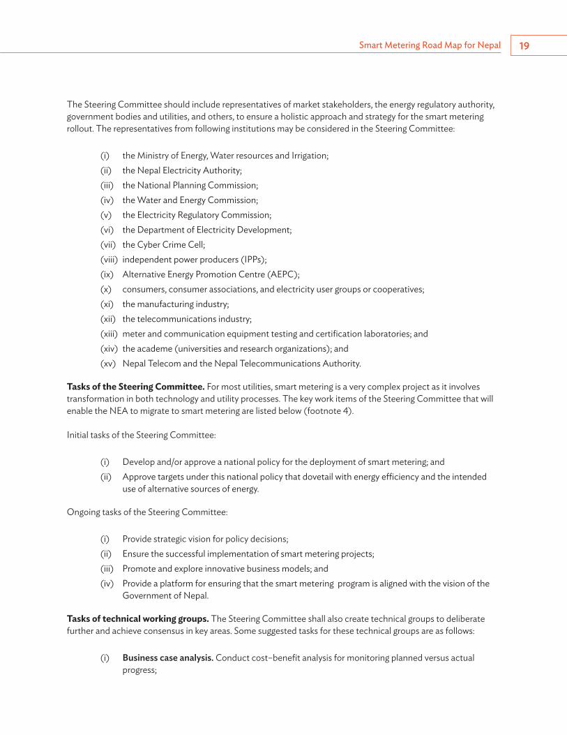
The Steering Committee should include representatives of market stakeholders, the energy regulatory authority, government bodies and utilities, and others, to ensure a holistic approach and strategy for the smart metering rollout. The representatives from following institutions may be considered in the Steering Committee:
(i) the Ministry of Energy, Water resources and Irrigation;(ii) the Nepal Electricity Authority;(iii) the National Planning Commission;(iv) the Water and Energy Commission;(v) the Electricity Regulatory Commission;(vi) the Department of Electricity Development;(vii) the Cyber Crime Cell; (viii) independent power producers (IPPs);(ix) Alternative Energy Promotion Centre (AEPC);(x) consumers, consumer associations, and electricity user groups or cooperatives; (xi) the manufacturing industry;(xii) the telecommunications industry; (xiii) meter and communication equipment testing and certification laboratories; and(xiv) the academe (universities and research organizations); and (xv) Nepal Telecom and the Nepal Telecommunications Authority.
Tasks of the Steering Committee. For most utilities, smart metering is a very complex project as it involves transformation in both technology and utility processes. The key work items of the Steering Committee that will enable the NEA to migrate to smart metering are listed below (footnote 4).
Initial tasks of the Steering Committee:
(i) Develop and/or approve a national policy for the deployment of smart metering; and(ii) Approve targets under this national policy that dovetail with energy efficiency and the intended
use of alternative sources of energy.
Ongoing tasks of the Steering Committee:
(i) Provide strategic vision for policy decisions;(ii) Ensure the successful implementation of smart metering projects;(iii) Promote and explore innovative business models; and(iv) Provide a platform for ensuring that the smart metering program is aligned with the vision of the
Government of Nepal.
Tasks of technical working groups. The Steering Committee shall also create technical groups to deliberate further and achieve consensus in key areas. Some suggested tasks for these technical groups are as follows:
(i) Business case analysis. Conduct cost–benefit analysis for monitoring planned versus actual progress;
Smart Metering Road Map for Nepal20
(ii) Communication standards. Compare and list open standards for telecommunications in a smart grid, including the finalization of the functional requirements for telecommunications infrastructure;
(iii) Technical specifications and functional requirements. Finalize the technical specifications and functional requirements for smart meters and the smart metering system as a whole;
(iv) System planning. Analyze load flow at various points in the electrical grid and provide recommendations for the future expansion of the power system;
(v) Transition to smart grid. Study other smart grid technologies for transitioning from smart metering to a smart grid;
(vi) Demand-side management. Identify appropriate incentives for consumers to shift demand from peak to off-peak hours; and
(vii) Regulatory and legal frameworks. Propose new regulatory and legal frameworks and update existing frameworks.
Technical groups shall include utility experts, electricity regulators, and representatives from government ministries, the academe, research and development organizations, and industry.
21
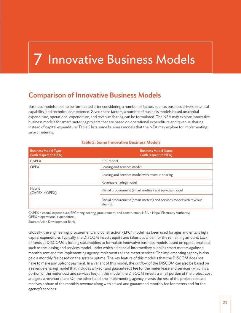
Comparison of Innovative Business ModelsBusiness models need to be formulated after considering a number of factors such as business drivers, financial capability, and technical competence. Given these factors, a number of business models based on capital expenditure, operational expenditure, and revenue sharing can be formulated. The NEA may explore innovative business models for smart metering projects that are based on operational expenditure and revenue sharing instead of capital expenditure. Table 5 lists some business models that the NEA may explore for implementing smart metering.
Table 5: Some Innovative Business Models
Business Model Type (with respect to NEA)
Business Model Name (with respect to NEA)
CAPEX EPC modelOPEX Leasing and services model
Leasing and services model with revenue sharing
Revenue-sharing modelHybrid (CAPEX + OPEX)
Partial procurement (smart meters) and services model
Partial procurement (smart meters) and services model with revenue sharing
CAPEX = capital expenditure; EPC = engineering, procurement, and construction; NEA = Nepal Electricity Authority; OPEX = operational expenditure.Source: Asian Development Bank.
Globally, the engineering, procurement, and construction (EPC) model has been used for ages and entails high capital expenditure. Typically, the DISCOM invests equity and takes out a loan for the remaining amount. Lack of funds at DISCOMs is forcing stakeholders to formulate innovative business models based on operational cost such as the leasing and services model, under which a financial intermediary supplies smart meters against a monthly rent and the implementing agency implements all the meter services. The implementing agency is also paid a monthly fee based on the system uptime. The key feature of this model is that the DISCOM does not have to make any upfront payment. In a variant of this model, the outflow of the DISCOM can also be based on a revenue-sharing model that includes a fixed (and guaranteed) fee for the meter lease and services (which is a portion of the meter cost and services fee). In this model, the DISCOM invests a small portion of the project cost and gets a revenue share. On the other hand, the implementing agency invests the rest of the project cost and receives a share of the monthly revenue along with a fixed and guaranteed monthly fee for meters and for the agency’s services.
7 Innovative Business Models
Smart Metering Road Map for Nepal22
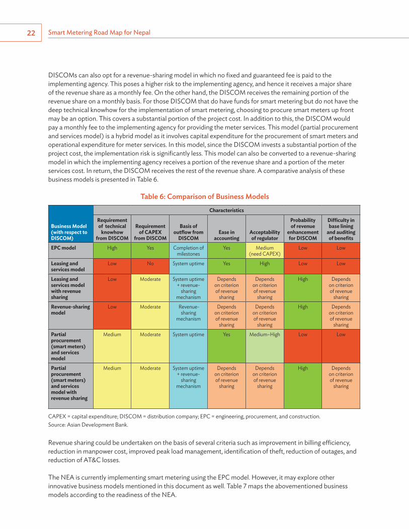
DISCOMs can also opt for a revenue-sharing model in which no fixed and guaranteed fee is paid to the implementing agency. This poses a higher risk to the implementing agency, and hence it receives a major share of the revenue share as a monthly fee. On the other hand, the DISCOM receives the remaining portion of the revenue share on a monthly basis. For those DISCOM that do have funds for smart metering but do not have the deep technical knowhow for the implementation of smart metering, choosing to procure smart meters up front may be an option. This covers a substantial portion of the project cost. In addition to this, the DISCOM would pay a monthly fee to the implementing agency for providing the meter services. This model (partial procurement and services model) is a hybrid model as it involves capital expenditure for the procurement of smart meters and operational expenditure for meter services. In this model, since the DISCOM invests a substantial portion of the project cost, the implementation risk is significantly less. This model can also be converted to a revenue-sharing model in which the implementing agency receives a portion of the revenue share and a portion of the meter services cost. In return, the DISCOM receives the rest of the revenue share. A comparative analysis of these business models is presented in Table 6.
Table 6: Comparison of Business Models
Business Model(with respect to DISCOM)
Characteristics
Requirement of technical
knowhow from DISCOM
Requirement of CAPEX
from DISCOM
Basis of outflow from
DISCOMEase in
accountingAcceptability of regulator
Probability of revenue
enhancement for DISCOM
Difficulty in base lining
and auditing of benefits
EPC model High Yes Completion of milestones
Yes Medium(need CAPEX)
Low Low
Leasing and services model
Low No System uptime Yes High Low Low
Leasing and services model with revenue sharing
Low Moderate System uptime + revenue-
sharing mechanism
Depends on criterion of revenue
sharing
Depends on criterion of revenue
sharing
High Depends on criterion of revenue
sharing
Revenue-sharing model
Low Moderate Revenue-sharing
mechanism
Depends on criterion of revenue
sharing
Depends on criterion of revenue
sharing
High Depends on criterion of revenue
sharing
Partial procurement (smart meters) and services model
Medium Moderate System uptime Yes Medium–High Low Low
Partial procurement (smart meters) and services model with revenue sharing
Medium Moderate System uptime + revenue-
sharing mechanism
Depends on criterion of revenue
sharing
Depends on criterion of revenue
sharing
High Depends on criterion of revenue
sharing
CAPEX = capital expenditure; DISCOM = distribution company; EPC = engineering, procurement, and construction.Source: Asian Development Bank.
Revenue sharing could be undertaken on the basis of several criteria such as improvement in billing efficiency, reduction in manpower cost, improved peak load management, identification of theft, reduction of outages, and reduction of AT&C losses.
The NEA is currently implementing smart metering using the EPC model. However, it may explore other innovative business models mentioned in this document as well. Table 7 maps the abovementioned business models according to the readiness of the NEA.
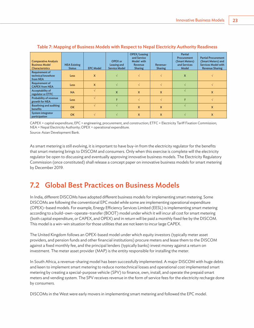
Innovative Business Models 23
Table 7: Mapping of Business Models with Respect to Nepal Electricity Authority Readiness
Comparative AnalysisBusiness Model Characteristics
NEA Existing Status EPC Model
OPEX or Leasing and
Service Model
OPEX/Leasing and Service Model with
Revenue Sharing
Revenue-Sharing
Partial Procurement
(Smart Meters) and Services
Model
Partial Procurement (Smart Meters) and Services Model with
Revenue SharingRequirement of technical knowhow from NEA
Less X √ √ √ X √
Requirement of CAPEX from NEA Less X √ √ √ √ √
Acceptability of regulator or ETFC NA √ X X X √ X
Probability of revenue growth for NEA Less √ ? √ √ ? √
Baselining and auditing benefits OK √ √ X X √ X
System integrator participation OK √ √ X X √ X
CAPEX = capital expenditure; EPC = engineering, procurement, and construction; ETFC = Electricity Tariff Fixation Commission; NEA = Nepal Electricity Authority; OPEX = operational expenditure.Source: Asian Development Bank.
As smart metering is still evolving, it is important to have buy-in from the electricity regulator for the benefits that smart metering brings to DISCOM and consumers. Only when this exercise is complete will the electricity regulator be open to discussing and eventually approving innovative business models. The Electricity Regulatory Commission (once constituted) shall release a concept paper on innovative business models for smart metering by December 2019.
7.2 Global Best Practices on Business Models In India, different DISCOMs have adopted different business models for implementing smart metering. Some DISCOMs are following the conventional EPC model while some are implementing operational expenditure (OPEX)–based models. For example, Energy Efficiency Services Limited (EESL) is implementing smart metering according to a build–own–operate–transfer (BOOT) model under which it will incur all cost for smart metering (both capital expenditure, or CAPEX, and OPEX) and in return will be paid a monthly fixed fee by the DISCOM. This model is a win–win situation for those utilities that are not keen to incur large CAPEX.
The United Kingdom follows an OPEX-based model under which equity investors (typically meter asset providers, and pension funds and other financial institutions) procure meters and lease them to the DISCOM against a fixed monthly fee, and the principal lenders (typically banks) invest money against a return on investment. The meter asset provider (MAP) is the entity responsible for installing the meter.
In South Africa, a revenue-sharing model has been successfully implemented. A major DISCOM with huge debts and keen to implement smart metering to reduce nontechnical losses and operational cost implemented smart metering by creating a special-purpose vehicle (SPV) to finance, own, install, and operate the prepaid smart meters and vending system. The SPV receives revenue in the form of service fees for the electricity recharge done by consumers.
DISCOMs in the West were early movers in implementing smart metering and followed the EPC model.
24
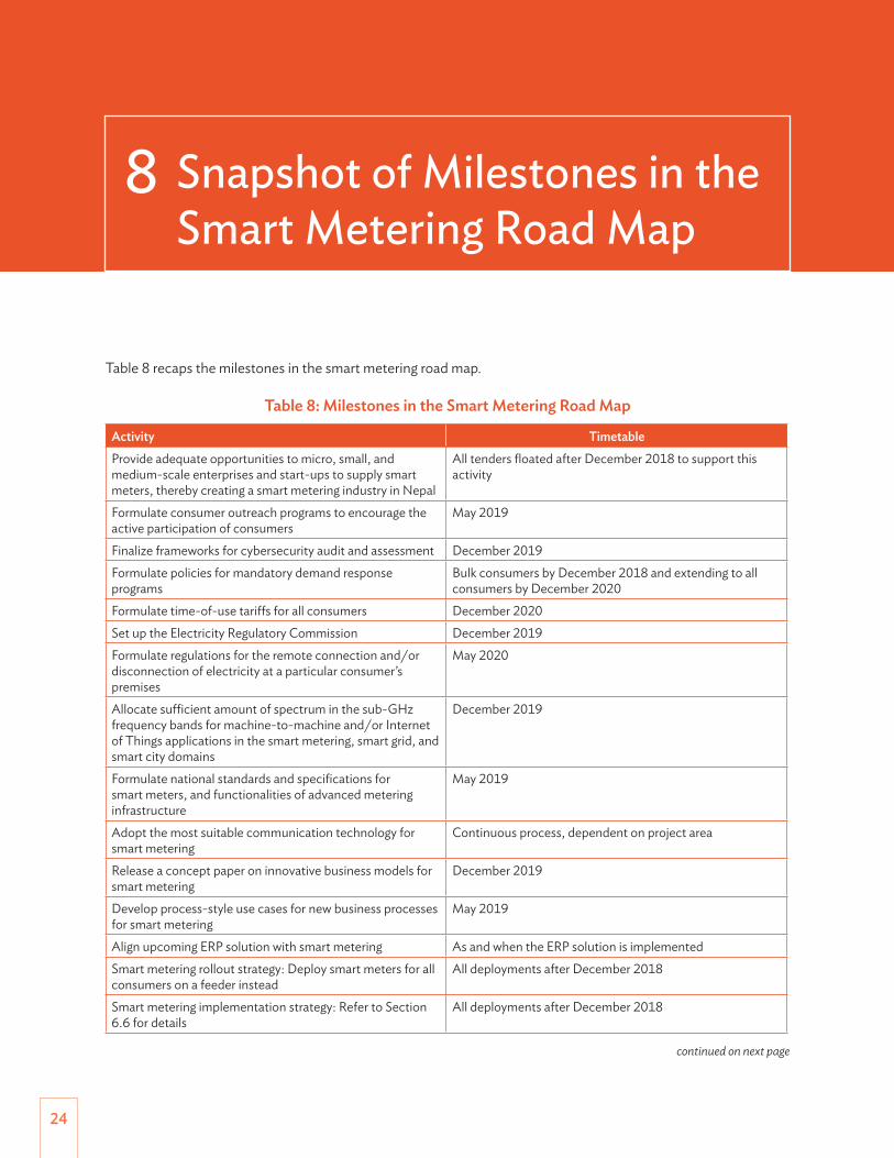
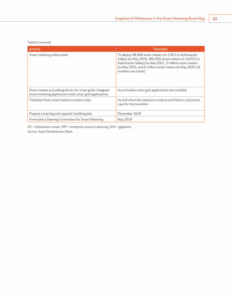
Table 8 recaps the milestones in the smart metering road map.
Table 8: Milestones in the Smart Metering Road Map
Activity TimetableProvide adequate opportunities to micro, small, and medium-scale enterprises and start-ups to supply smart meters, thereby creating a smart metering industry in Nepal
All tenders floated after December 2018 to support this activity
Formulate consumer outreach programs to encourage the active participation of consumers
May 2019
Finalize frameworks for cybersecurity audit and assessment December 2019Formulate policies for mandatory demand response programs
Bulk consumers by December 2018 and extending to all consumers by December 2020
Formulate time-of-use tariffs for all consumers December 2020Set up the Electricity Regulatory Commission December 2019Formulate regulations for the remote connection and/or disconnection of electricity at a particular consumer’s premises
May 2020
Allocate sufficient amount of spectrum in the sub-GHz frequency bands for machine-to-machine and/or Internet of Things applications in the smart metering, smart grid, and smart city domains
December 2019
Formulate national standards and specifications for smart meters, and functionalities of advanced metering infrastructure
May 2019
Adopt the most suitable communication technology for smart metering
Continuous process, dependent on project area
Release a concept paper on innovative business models for smart metering
December 2019
Develop process-style use cases for new business processes for smart metering
May 2019
Align upcoming ERP solution with smart metering As and when the ERP solution is implementedSmart metering rollout strategy: Deploy smart meters for all consumers on a feeder instead
All deployments after December 2018
Smart metering implementation strategy: Refer to Section 6.6 for details
All deployments after December 2018
8 Snapshot of Milestones in the Smart Metering Road Map
continued on next page
Snapshot of Milestones in the Smart Metering Road Map 25
Activity TimetableSmart metering rollout plan To deploy 98,000 smart meters (in 2 DCs in Kathmandu
Valley) by May 2020, 450,000 smart meters (in 10 DCs in Kathmandu Valley) by May 2021, 3 million smart meters by May 2023, and 5 million smart meters by May 2025 (all numbers are totals)
Smart meters as building blocks for smart grids: Integrate smart metering applications with smart grid applications
As and when smart grid applications are installed
Transition from smart meters to smart cities As and when the industry is mature and there is a business case for the transition
Prepare a training and capacity-building plan December 2019Formulate a Steering Committee for Smart Metering May 2019
DC = distribution center, ERP = enterprise resource planning, GHz = gigahertz.Source: Asian Development Bank.
Table 8 continued
26
The Nepal power sector is at the threshold of a technology revolution. It is about to embrace the digital technology wave by implementing smart metering, which will allow it to enhance operational efficiency and also implement a smart grid.
While the drivers for implementing smart metering in Nepal are clear, several initiatives have yet to be taken by Nepal at the policy, regulatory, and standardization level. It is important to identify innovative business models that are acceptable and beneficial to both industry and the NEA. In economies similar to Nepal, the OPEX-based business model is often preferred over the conventional CAPEX-based business model.
The formulation of new business processes for smart metering will also be pivotal to the success of the smart metering journey. The NEA will not only have to deliberate deeply but also foster a culture in which its personnel easily adopt new business processes pertaining to smart metering.
The smart metering infrastructure shall be used as a building block for implementing a smart grid, and hence the NEA shall integrate smart metering applications with smart grid applications as and when smart grid applications are installed.
9 Conclusion
27
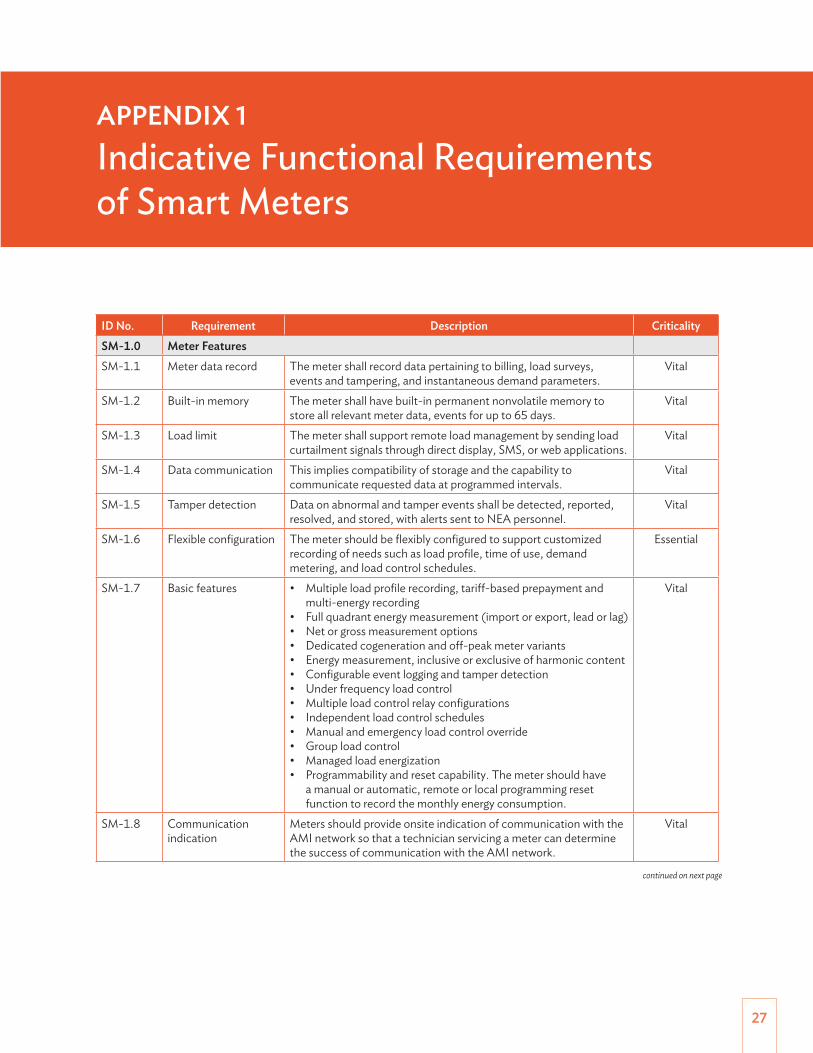
APPENDIX 1Indicative Functional Requirements of Smart Meters
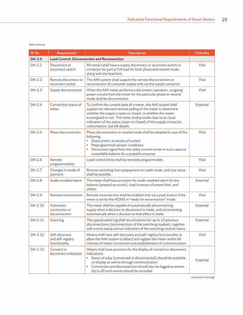
ID No. Requirement Description CriticalitySM-1.0 Meter FeaturesSM-1.1 Meter data record The meter shall record data pertaining to billing, load surveys,
events and tampering, and instantaneous demand parameters.Vital
SM-1.2 Built-in memory The meter shall have built-in permanent nonvolatile memory to store all relevant meter data, events for up to 65 days.
Vital
SM-1.3 Load limit The meter shall support remote load management by sending load curtailment signals through direct display, SMS, or web applications.
Vital
SM-1.4 Data communication This implies compatibility of storage and the capability to communicate requested data at programmed intervals.
Vital
SM-1.5 Tamper detection Data on abnormal and tamper events shall be detected, reported, resolved, and stored, with alerts sent to NEA personnel.
Vital
SM-1.6 Flexible configuration The meter should be flexibly configured to support customized recording of needs such as load profile, time of use, demand metering, and load control schedules.
Essential
SM-1.7 Basic features • Multiple load profile recording, tariff-based prepayment and multi-energy recording
• Full quadrant energy measurement (import or export, lead or lag)• Net or gross measurement options• Dedicated cogeneration and off-peak meter variants• Energy measurement, inclusive or exclusive of harmonic content• Configurable event logging and tamper detection• Under frequency load control• Multiple load control relay configurations• Independent load control schedules• Manual and emergency load control override• Group load control• Managed load energization• Programmability and reset capability. The meter should have
a manual or automatic, remote or local programming reset function to record the monthly energy consumption.
Vital
SM-1.8 Communication indication
Meters should provide onsite indication of communication with the AMI network so that a technician servicing a meter can determine the success of communication with the AMI network.
Vital
continued on next page
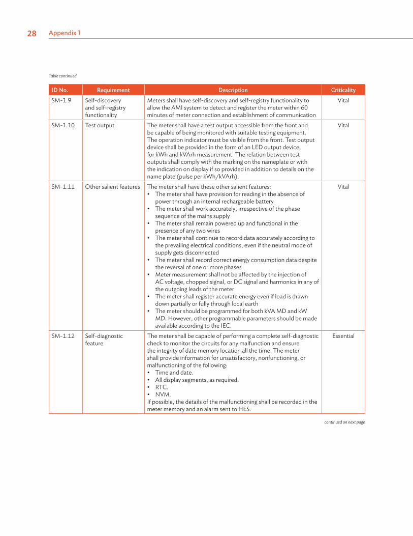
Appendix 128
ID No. Requirement Description CriticalitySM-1.9 Self-discovery
and self-registry functionality
Meters shall have self-discovery and self-registry functionality to allow the AMI system to detect and register the meter within 60 minutes of meter connection and establishment of communication
Vital
SM-1.10 Test output The meter shall have a test output accessible from the front and be capable of being monitored with suitable testing equipment. The operation indicator must be visible from the front. Test output device shall be provided in the form of an LED output device, for kWh and kVArh measurement. The relation between test outputs shall comply with the marking on the nameplate or with the indication on display if so provided in addition to details on the name plate (pulse per kWh/kVArh).
Vital
SM-1.11 Other salient features The meter shall have these other salient features:• The meter shall have provision for reading in the absence of
power through an internal rechargeable battery• The meter shall work accurately, irrespective of the phase
sequence of the mains supply• The meter shall remain powered up and functional in the
presence of any two wires• The meter shall continue to record data accurately according to
the prevailing electrical conditions, even if the neutral mode of supply gets disconnected
• The meter shall record correct energy consumption data despite the reversal of one or more phases
• Meter measurement shall not be affected by the injection of AC voltage, chopped signal, or DC signal and harmonics in any of the outgoing leads of the meter
• The meter shall register accurate energy even if load is drawn down partially or fully through local earth
• The meter should be programmed for both kVA MD and kW MD. However, other programmable parameters should be made available according to the IEC.
Vital
SM-1.12 Self-diagnostic feature
The meter shall be capable of performing a complete self-diagnostic check to monitor the circuits for any malfunction and ensure the integrity of date memory location all the time. The meter shall provide information for unsatisfactory, nonfunctioning, or malfunctioning of the following:• Time and date.• All display segments, as required.• RTC.• NVM.If possible, the details of the malfunctioning shall be recorded in the meter memory and an alarm sent to HES.
Essential
Table continued
continued on next page
Indicative Functional Requirements of Smart Meters 29
ID No. Requirement Description CriticalitySM-2.0 Load Control: Disconnection and ReconnectionSM-2.1 Disconnect or
reconnect switchAll meters shall have a supply disconnect or reconnect switch or contactor for part or full load for both phase and neutral mode, along with the load limit.
Vital
SM-2.2 Remote disconnect or reconnect switch
The AMI system shall support the remote disconnection or reconnection of consumer supply only via the supply contactor.
Vital
SM-2.3 Supply disconnection When the AMI meter performs a disconnect operation, outgoing power circuits from the meter for the particular phase or neutral mode shall be disconnected.
Vital
SM-2.4 Connection status of meter
To confirm the current state of a meter, the AMI system shall support on-demand remote polling of the meter to determine whether the supply is open or closed, or whether the meter is energized or not. The meter shall provide clear local visual indication of the status (open or closed) of the supply contactor, consumption, last bill details.
Essential
SM-2.5 Phase disconnection Phase disconnection or neutral mode shall be adopted in case of the following:• Overcurrent, or excess of current• Preprogrammed tamper conditions• Disconnect signal from the utility control center in such cases as
unavailable balance for a prepaid consumer
Vital
SM-2.6 Remote programmability
Load control limits shall be remotely programmable. Vital
SM-2.7 Changes in mode of payment
Remote switching from prepayment to credit mode, and vice versa, shall be possible.
Vital
SM-2.8 Audio-enabled alarm The meter shall have provision for audio-enabled alarm for low balance (prepaid accounts), load in excess of preset limit, and others.
Essential
SM-2.9 Remote reconnection Remote reconnection shall be enabled only via a push button if the meter is set by the MDMS in “ready for reconnection” mode.
Vital
SM-2.10 Automatic connection or disconnection
The meter shall be capable of automatically disconnecting supply when a decision to disconnect is made, and reconnecting automatically when a decision to that effect is made.
Essential
SM-2.11 Event log The special event log shall record entries for up to 10 previous disconnections (reconnections of the switching module), together with a time stamp and an indication of the switching module status.
Essential
SM-2.12 Self-discovery and self-registry functionality
Meters shall have self-discovery and self-registry functionality to allow the AMI system to detect and register the meter within 60 minutes of meter connection and establishment of communication.
Vital
SM-2.13 Connect or disconnect indication
Meters shall have provision for the display of connect or disconnect indications: • Status of relay (connected or disconnected) should be available
on display as well as through communication• Connection and disconnection should also be logged as events.
Up to 20 such events should be recorded
Essential
Table continued
continued on next page
Appendix 130
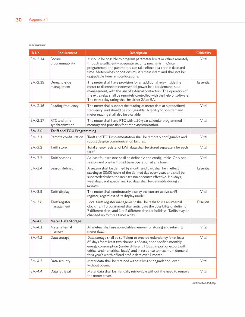
ID No. Requirement Description CriticalitySM-2.14 Secure
programmabilityIt should be possible to program parameter limits or values remotely through a sufficiently adequate security mechanism. Once programmed, the parameters can take effect at a certain date and time. Meteorology conditions must remain intact and shall not be upgradable from remote locations.
Vital
SM-2.15 Demand-side management
The meter shall have provision for an additional relay inside the meter to disconnect nonessential power load for demand-side management, with the use of external contactors. The operation of the extra relay shall be remotely controlled with the help of software. The extra relay rating shall be either 2A or 5A.
Essential
SM-2.16 Reading frequency The meter shall support the reading of meter data at a predefined frequency, and should be configurable. A facility for on-demand meter reading shall also be available.
Vital
SM-2.17 RTC and time synchronization
The meter shall have RTC with a 20-year calendar programmed in memory and provision for time synchronization.
Vital
SM-3.0 Tariff and TOU ProgrammingSM-3.1 Remote configuration Tariff and TOU implementation shall be remotely configurable and
robust despite communication failures.Vital
SM-3.2 Tariff store Total energy register of kWh data shall be stored separately for each tariff.
Vital
SM-3.3 Tariff seasons At least four seasons shall be definable and configurable. Only one season and one tariff shall be in operation at any time.
Vital
SM-3.4 Season defined A season shall be defined by month and day, shall be in effect starting at 00:00 hours of the defined day every year, and shall be superseded when the next season becomes effective. Holidays, weekdays, and special marked days shall be definable during a season.
Essential
SM-3.5 Tariff display The meter shall continuously display the current active tariff register, regardless of its display mode.
Vital
SM-3.6 Tariff register management
Local tariff register management shall be realized via an internal clock. Tariff programmed shall anticipate the possibility of defining 7 different days, and 1 or 2 different days for holidays. Tariffs may be changed up to three times a day.
Essential
SM-4.0 Meter Data StorageSM-4.1 Meter internal
memoryAll meters shall use nonvolatile memory for storing and retaining meter data.
Vital
SM-4.2 Data storage Data storage shall be sufficient to provide redundancy for at least 65 days for at least two channels of data, at a specified monthly energy consumption (under different TOUs, import or export with critical and noncritical loads) and in response to maximum demand for a year’s worth of load profile data over 1 month.
Vital
SM-4.3 Data security Meter data shall be retained without loss or degradation, even without power.
Vital
SM-4.4 Data retrieval Meter data shall be manually retrievable without the need to remove the meter cover.
Vital
Table continued
continued on next page
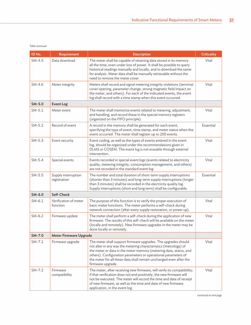
Indicative Functional Requirements of Smart Meters 31
ID No. Requirement Description CriticalitySM-4.5 Data download The meter shall be capable of retaining data stored in its memory
all the time, even under loss of power. It shall be possible to query historical readings manually and locally, and to download the same for analysis. Meter data shall be manually retrievable without the need to remove the meter cover.
Vital
SM-4.6 Meter integrity Meters shall record and signal metering integrity violations (terminal cover opening, parameter change, strong magnetic field impact on the meter, and others). For each of the indicated events, the event log shall record with a time stamp when this event occurred.
Vital
SM-5.0 Event LogSM-5.1 Meter event The meter shall memorize events related to metering, adjustment,
and handling, and record these in the special memory registers (organized on the FIFO principle).
Vital
SM-5.2 Record of event A record in the memory shall be generated for each event, specifying the type of event, time stamp, and meter status when the event occurred. The meter shall register up to 200 events.
Essential
SM-5.3 Event security Event coding, as well as the types of events entered in the event log, should be organized under the recommendations given in DLMS or COSEM. The event log is not erasable through external intervention.
Vital
SM-5.4 Special events Events recorded in special event logs (events related to electricity quality, metering integrity, consumption management, and others) are not recorded in the standard event log.
Vital
SM-5.5 Supply interruption registration
The number and total duration of short-term supply interruptions (shorter than 3 minutes) and long-term supply interruptions (longer than 3 minutes) shall be recorded in the electricity quality log. Supply interruptions (short and long term) shall be configurable.
Essential
SM-6.0 Self-CheckSM-6.1 Verification of meter
functionThe purpose of this function is to verify the proper execution of basic meter functions. The meter performs a self-check during network connection (after every supply restoration, or power up).
Vital
SM-6.2 Firmware update The meter shall perform a self-check during the application of new firmware. The results of this self-check will be available on the meter (locally and remotely). New firmware upgrades in the meter may be done locally or remotely.
Vital
SM-7.0 Meter Firmware UpgradeSM-7.1 Firmware upgrade The meter shall support firmware upgrades. The upgrades should
not alter in any way the metering characteristics (metrology) of the meter or data in the meter memory (metering data, status, and others). Configuration parameters or operational parameters of the meter for all these data shall remain unchanged even after the firmware upgrade.
Vital
SM-7.2 Firmware compatibility
The meter, after receiving new firmware, will verify its compatibility; if that verification does not end positively, the new firmware will not be executed. The meter will record the time and date of receipt of new firmware, as well as the time and date of new firmware application, in the event log.
Vital
Table continued
continued on next page
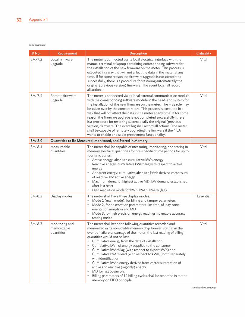
Appendix 132
ID No. Requirement Description CriticalitySM-7.3 Local firmware
upgradeThe meter is connected via its local electrical interface with the manual terminal or laptop containing corresponding software for the installation of the new firmware on the meter. This process is executed in a way that will not affect the data in the meter at any time. If for some reason the firmware upgrade is not completed successfully, there is a procedure for restoring automatically the original (previous version) firmware. The event log shall record all actions.
Vital
SM-7.4 Remote firmware upgrade
The meter is connected via its local external communication module with the corresponding software module in the head-end system for the installation of the new firmware on the meter. The HES role may be taken over by the concentrators. This process is executed in a way that will not affect the data in the meter at any time. If for some reason the firmware upgrade is not completed successfully, there is a procedure for restoring automatically the original (previous version) firmware. The event log shall record all actions. The meter shall be capable of remotely upgrading the firmware if the NEA wants to enable or disable prepayment functionality.
Vital
SM-8.0 Quantities to Be Measured, Monitored, and Stored in MemorySM-8.1 Measureable
quantitiesThe meter shall be capable of measuring, monitoring, and storing in memory electrical quantities for pre-specified time periods for up to four time zones.• Active energy: absolute cumulative kWh energy• Reactive energy: cumulative kVArh lag with respect to active
energy• Apparent energy: cumulative absolute kVAh derived vector sum
of reactive and active energy• Maximum demand: highest active MD, kW demand established
after last reset• High resolution mode for kWh, kVAh, kVArh (lag)
Vital
SM-8.2 Display modes The meter shall have three display modes:• Mode 1 (main mode), for billing and tamper parameters• Mode 2, for observation parameters like time-of-day zone
energy consumption and MD• Mode 3, for high precision energy readings, to enable accuracy
testing onsite
Essential
SM-8.3 Monitoring and memorizable quantities
The meter shall keep the following quantities recorded and memorized in its nonvolatile memory chip forever, so that in the event of failure or damage of the meter, the last reading of billing quantities would not be lost.• Cumulative energy from the date of installation• Cumulative kWh of energy supplied to the consumer• Cumulative kVArh lag (with respect to export kWh) and
Cumulative kVArh lead (with respect to kWh), both separately with identification
• Cumulative kVAh energy derived from vector summation of active and reactive (lag only) energy
• MD for last power on.• Billing parameters of 12 billing cycles shall be recorded in meter
memory on FIFO principle.
Vital
Table continued
continued on next page
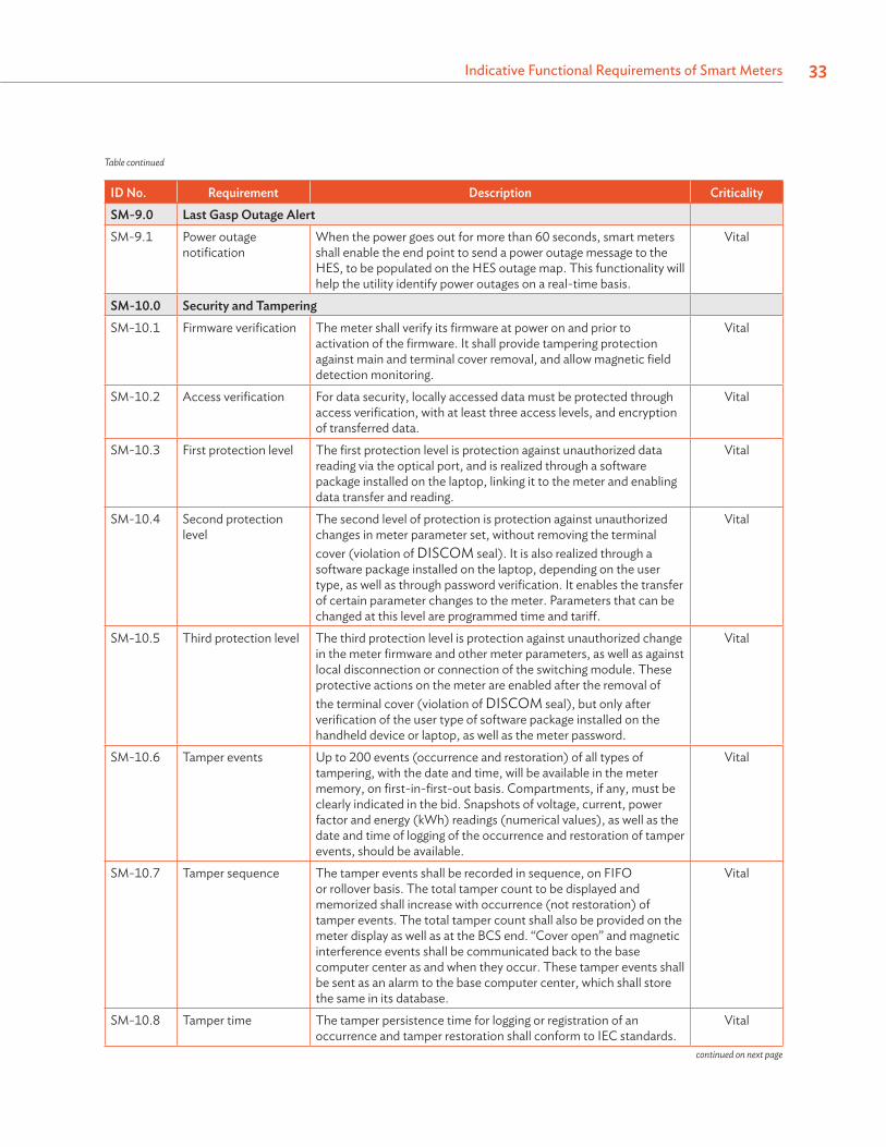
Indicative Functional Requirements of Smart Meters 33
ID No. Requirement Description CriticalitySM-9.0 Last Gasp Outage AlertSM-9.1 Power outage
notificationWhen the power goes out for more than 60 seconds, smart meters shall enable the end point to send a power outage message to the HES, to be populated on the HES outage map. This functionality will help the utility identify power outages on a real-time basis.
Vital
SM-10.0 Security and TamperingSM-10.1 Firmware verification The meter shall verify its firmware at power on and prior to
activation of the firmware. It shall provide tampering protection against main and terminal cover removal, and allow magnetic field detection monitoring.
Vital
SM-10.2 Access verification For data security, locally accessed data must be protected through access verification, with at least three access levels, and encryption of transferred data.
Vital
SM-10.3 First protection level The first protection level is protection against unauthorized data reading via the optical port, and is realized through a software package installed on the laptop, linking it to the meter and enabling data transfer and reading.
Vital
SM-10.4 Second protection level
The second level of protection is protection against unauthorized changes in meter parameter set, without removing the terminal cover (violation of DISCOM seal). It is also realized through a software package installed on the laptop, depending on the user type, as well as through password verification. It enables the transfer of certain parameter changes to the meter. Parameters that can be changed at this level are programmed time and tariff.
Vital
SM-10.5 Third protection level The third protection level is protection against unauthorized change in the meter firmware and other meter parameters, as well as against local disconnection or connection of the switching module. These protective actions on the meter are enabled after the removal of the terminal cover (violation of DISCOM seal), but only after verification of the user type of software package installed on the handheld device or laptop, as well as the meter password.
Vital
SM-10.6 Tamper events Up to 200 events (occurrence and restoration) of all types of tampering, with the date and time, will be available in the meter memory, on first-in-first-out basis. Compartments, if any, must be clearly indicated in the bid. Snapshots of voltage, current, power factor and energy (kWh) readings (numerical values), as well as the date and time of logging of the occurrence and restoration of tamper events, should be available.
Vital
SM-10.7 Tamper sequence The tamper events shall be recorded in sequence, on FIFO or rollover basis. The total tamper count to be displayed and memorized shall increase with occurrence (not restoration) of tamper events. The total tamper count shall also be provided on the meter display as well as at the BCS end. “Cover open” and magnetic interference events shall be communicated back to the base computer center as and when they occur. These tamper events shall be sent as an alarm to the base computer center, which shall store the same in its database.
Vital
SM-10.8 Tamper time The tamper persistence time for logging or registration of an occurrence and tamper restoration shall conform to IEC standards.
Vital
Table continued
continued on next page
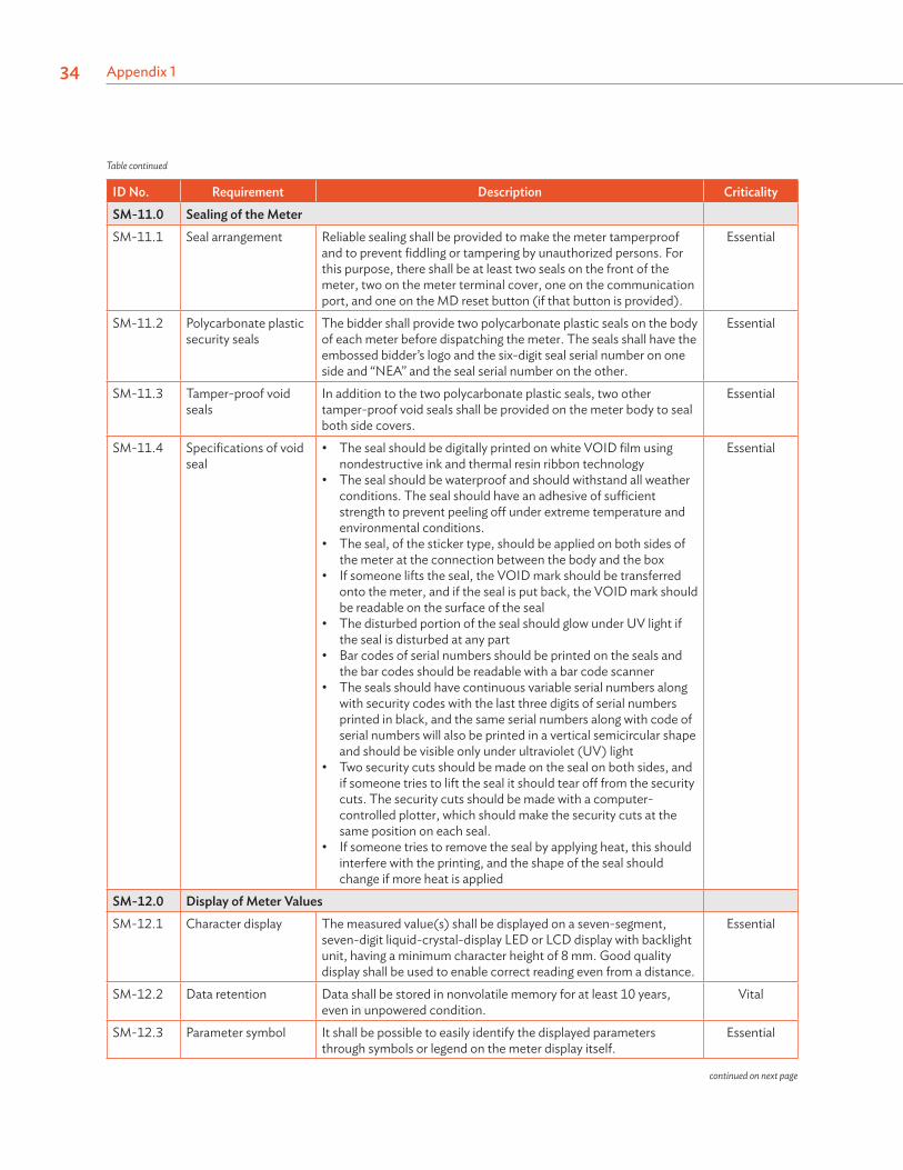
Appendix 134
ID No. Requirement Description CriticalitySM-11.0 Sealing of the MeterSM-11.1 Seal arrangement Reliable sealing shall be provided to make the meter tamperproof
and to prevent fiddling or tampering by unauthorized persons. For this purpose, there shall be at least two seals on the front of the meter, two on the meter terminal cover, one on the communication port, and one on the MD reset button (if that button is provided).
Essential
SM-11.2 Polycarbonate plastic security seals
The bidder shall provide two polycarbonate plastic seals on the body of each meter before dispatching the meter. The seals shall have the embossed bidder’s logo and the six-digit seal serial number on one side and “NEA” and the seal serial number on the other.
Essential
SM-11.3 Tamper-proof void seals
In addition to the two polycarbonate plastic seals, two other tamper-proof void seals shall be provided on the meter body to seal both side covers.
Essential
SM-11.4 Specifications of void seal
• The seal should be digitally printed on white VOID film using nondestructive ink and thermal resin ribbon technology
• The seal should be waterproof and should withstand all weather conditions. The seal should have an adhesive of sufficient strength to prevent peeling off under extreme temperature and environmental conditions.
• The seal, of the sticker type, should be applied on both sides of the meter at the connection between the body and the box
• If someone lifts the seal, the VOID mark should be transferred onto the meter, and if the seal is put back, the VOID mark should be readable on the surface of the seal
• The disturbed portion of the seal should glow under UV light if the seal is disturbed at any part
• Bar codes of serial numbers should be printed on the seals and the bar codes should be readable with a bar code scanner
• The seals should have continuous variable serial numbers along with security codes with the last three digits of serial numbers printed in black, and the same serial numbers along with code of serial numbers will also be printed in a vertical semicircular shape and should be visible only under ultraviolet (UV) light
• Two security cuts should be made on the seal on both sides, and if someone tries to lift the seal it should tear off from the security cuts. The security cuts should be made with a computer-controlled plotter, which should make the security cuts at the same position on each seal.
• If someone tries to remove the seal by applying heat, this should interfere with the printing, and the shape of the seal should change if more heat is applied
Essential
SM-12.0 Display of Meter ValuesSM-12.1 Character display The measured value(s) shall be displayed on a seven-segment,
seven-digit liquid-crystal-display LED or LCD display with backlight unit, having a minimum character height of 8 mm. Good quality display shall be used to enable correct reading even from a distance.
Essential
SM-12.2 Data retention Data shall be stored in nonvolatile memory for at least 10 years, even in unpowered condition.
Vital
SM-12.3 Parameter symbol It shall be possible to easily identify the displayed parameters through symbols or legend on the meter display itself.
Essential
Table continued
continued on next page
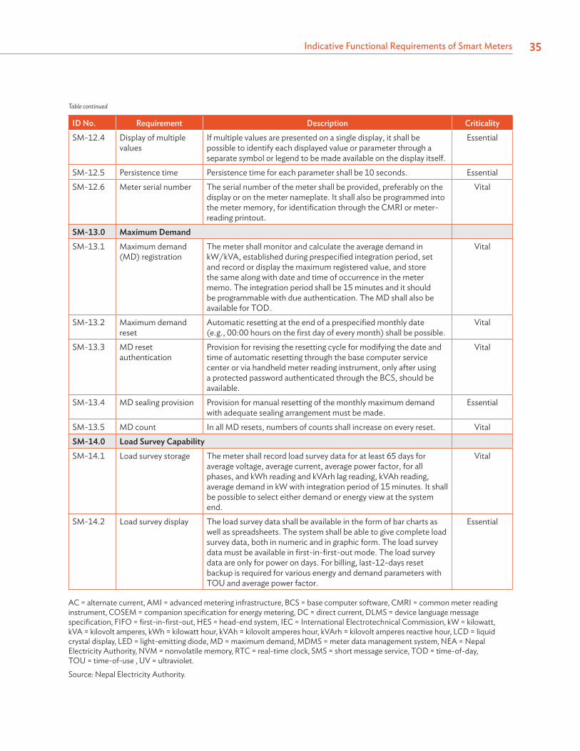
Indicative Functional Requirements of Smart Meters 35
ID No. Requirement Description CriticalitySM-12.4 Display of multiple
valuesIf multiple values are presented on a single display, it shall be possible to identify each displayed value or parameter through a separate symbol or legend to be made available on the display itself.
Essential
SM-12.5 Persistence time Persistence time for each parameter shall be 10 seconds. EssentialSM-12.6 Meter serial number The serial number of the meter shall be provided, preferably on the
display or on the meter nameplate. It shall also be programmed into the meter memory, for identification through the CMRI or meter-reading printout.
Vital
SM-13.0 Maximum DemandSM-13.1 Maximum demand
(MD) registrationThe meter shall monitor and calculate the average demand in kW/kVA, established during prespecified integration period, set and record or display the maximum registered value, and store the same along with date and time of occurrence in the meter memo. The integration period shall be 15 minutes and it should be programmable with due authentication. The MD shall also be available for TOD.
Vital
SM-13.2 Maximum demand reset
Automatic resetting at the end of a prespecified monthly date (e.g., 00:00 hours on the first day of every month) shall be possible.
Vital
SM-13.3 MD reset authentication
Provision for revising the resetting cycle for modifying the date and time of automatic resetting through the base computer service center or via handheld meter reading instrument, only after using a protected password authenticated through the BCS, should be available.
Vital
SM-13.4 MD sealing provision Provision for manual resetting of the monthly maximum demand with adequate sealing arrangement must be made.
Essential
SM-13.5 MD count In all MD resets, numbers of counts shall increase on every reset. VitalSM-14.0 Load Survey CapabilitySM-14.1 Load survey storage The meter shall record load survey data for at least 65 days for
average voltage, average current, average power factor, for all phases, and kWh reading and kVArh lag reading, kVAh reading, average demand in kW with integration period of 15 minutes. It shall be possible to select either demand or energy view at the system end.
Vital
SM-14.2 Load survey display The load survey data shall be available in the form of bar charts as well as spreadsheets. The system shall be able to give complete load survey data, both in numeric and in graphic form. The load survey data must be available in first-in-first-out mode. The load survey data are only for power on days. For billing, last-12-days reset backup is required for various energy and demand parameters with TOU and average power factor.
Essential
AC = alternate current, AMI = advanced metering infrastructure, BCS = base computer software, CMRI = common meter reading instrument, COSEM = companion specification for energy metering, DC = direct current, DLMS = device language message specification, FIFO = first-in-first-out, HES = head-end system, IEC = International Electrotechnical Commission, kW = kilowatt, kVA = kilovolt amperes, kWh = kilowatt hour, kVAh = kilovolt amperes hour, kVArh = kilovolt amperes reactive hour, LCD = liquid crystal display, LED = light-emitting diode, MD = maximum demand, MDMS = meter data management system, NEA = Nepal Electricity Authority, NVM = nonvolatile memory, RTC = real-time clock, SMS = short message service, TOD = time-of-day, TOU = time-of-use , UV = ultraviolet.
Source: Nepal Electricity Authority.
Table continued
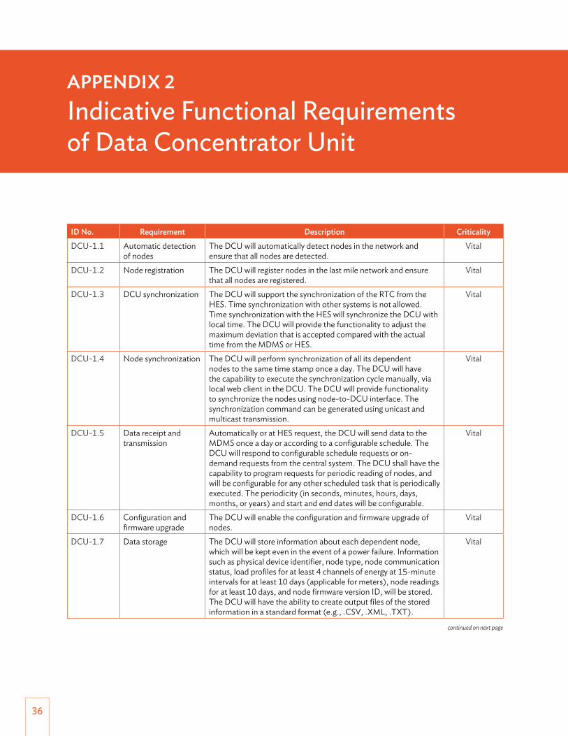
36
ID No. Requirement Description CriticalityDCU-1.1 Automatic detection
of nodesThe DCU will automatically detect nodes in the network and ensure that all nodes are detected.
Vital
DCU-1.2 Node registration The DCU will register nodes in the last mile network and ensure that all nodes are registered.
Vital
DCU-1.3 DCU synchronization The DCU will support the synchronization of the RTC from the HES. Time synchronization with other systems is not allowed. Time synchronization with the HES will synchronize the DCU with local time. The DCU will provide the functionality to adjust the maximum deviation that is accepted compared with the actual time from the MDMS or HES.
Vital
DCU-1.4 Node synchronization The DCU will perform synchronization of all its dependent nodes to the same time stamp once a day. The DCU will have the capability to execute the synchronization cycle manually, via local web client in the DCU. The DCU will provide functionality to synchronize the nodes using node-to-DCU interface. The synchronization command can be generated using unicast and multicast transmission.
Vital
DCU-1.5 Data receipt and transmission
Automatically or at HES request, the DCU will send data to the MDMS once a day or according to a configurable schedule. The DCU will respond to configurable schedule requests or on-demand requests from the central system. The DCU shall have the capability to program requests for periodic reading of nodes, and will be configurable for any other scheduled task that is periodically executed. The periodicity (in seconds, minutes, hours, days, months, or years) and start and end dates will be configurable.
Vital
DCU-1.6 Configuration and firmware upgrade
The DCU will enable the configuration and firmware upgrade of nodes.
Vital
DCU-1.7 Data storage The DCU will store information about each dependent node, which will be kept even in the event of a power failure. Information such as physical device identifier, node type, node communication status, load profiles for at least 4 channels of energy at 15-minute intervals for at least 10 days (applicable for meters), node readings for at least 10 days, and node firmware version ID, will be stored. The DCU will have the ability to create output files of the stored information in a standard format (e.g., .CSV, .XML, .TXT).
Vital
APPENDIX 2Indicative Functional Requirements of Data Concentrator Unit
continued on next page

Indicative Functional Requirements of Data Concentrator Unit 37
ID No. Requirement Description CriticalityDCU-1.8 DCU memory Once the available memory is full for a particular parameter, the
oldest data shall be deleted first and will be replaced with the most recent data (FIFO).
Vital
DCU-1.9 Deregistration of node In cases where a node changes its DCU ownership, the DCU will be able to update its node list, but will continue to store data from the deregistered node.
Vital
CSV = comma-separated values, DCU = data concentrator unit, FIFO = first-in-first-out, HES = head-end system, ID = identification, MDMS = meter data management system, RTC = real-time clock, TXT = text, XML = extensible mark-up language.Source: Nepal Electricity Authority.
Table continued

38
ID No. Requirement Description CriticalityAP-1.1 Automatic detection
of nodesThe access point will automatically detect nodes in the network and ensure that all nodes are detected.
Vital
AP-1.2 Node registration The access point will register nodes in the last-mile network and ensure all nodes are registered.
Vital
AP-1.3 Access point synchronization
The access point will support the synchronization of the RTC from the HES. Time synchronization with other systems is not allowed. Time synchronization with HES will synchronize the access point with local time. The access point will provide functionality to adjust the maximum deviation that is accepted compared with the actual time from the MDMS or HES.
Vital
AP-1.4 Node synchronization
The access point will perform synchronization of all its dependent nodes to the same time stamp, once a day. The access point will have the capability to execute the synchronization cycle manually, via local web client in access point. The access point will provide functionality to synchronize the nodes using node to access point interface. The synchronization command can be generated using unicast and multicast transmission.
Vital
AP-1.5 Data receipt and transmission
Automatically or at the request of the HES, the access point will send data to the MDMS once a day or according to a configurable schedule. The access point will respond to configurable schedule requests or on-demand requests from the central system.
Vital
AP-1.6 Configuration and firmware upgrade
The access point will enable configuration and firmware upgrade of nodes. Vital
AP-1.7 Data storage The access point will store information about each dependent node, which will be kept even in the event of a power failure. Information such as physical device identifier, node type, node communication status, load profiles for at least four channels of energy at 15-minute intervals for at least 3 days (applicable to meters), node readings for at least 5 days, and node firmware version ID, will be stored. The access point will have the ability to create output files of the stored information in a standard format (e.g., .CSV, .XML, .TXT).
Vital
AP-1.8 Access point memory
Once the available memory is full for a particular parameter, the oldest data will be deleted first, to be replaced with the most recent data (FIFO).
Vital
AP-1.9 Deregistration of node
In cases where a node changes its access point ownership, the access point will be able to update its node list, but continue to store data from the de-registered node.
Vital
CSV = comma-separated values, DCU = data concentrator unit, FIFO = first-in-first-out, HES = head-end system, ID = identification, MDMS = meter data management system, RTC = real-time clock, TXT = text, XML = extensible mark-up language.
Source: Nepal Electricity Authority.
APPENDIX 3Indicative Functional Requirements of Router and Access Point
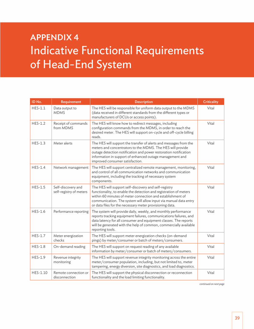
39
ID No. Requirement Description CriticalityHES-1.1 Data output to
MDMSThe HES will be responsible for uniform data output to the MDMS (data received in different standards from the different types or manufacturers of DCUs or access points).
Vital
HES-1.2 Receipt of commands from MDMS
The HES will know how to redirect messages, including configuration commands from the MDMS, in order to reach the desired meter. The HES will support on-cycle and off-cycle billing reads.
Vital
HES-1.3 Meter alerts The HES will support the transfer of alerts and messages from the meters and concentrators to the MDMS. The HES will provide outage detection notification and power restoration notification information in support of enhanced outage management and improved consumer satisfaction.
Vital
HES-1.4 Network management The HES will support centralized remote management, monitoring, and control of all communication networks and communication equipment, including the tracking of necessary system components.
Vital
HES-1.5 Self-discovery and self-registry of meters
The HES will support self-discovery and self-registry functionality, to enable the detection and registration of meters within 60 minutes of meter connection and establishment of communication. The system will allow input via manual data entry or data files for the necessary meter provisioning data.
Vital
HES-1.6 Performance reporting The system will provide daily, weekly, and monthly performance reports tracking equipment failures, communications failures, and data latency for all consumer and equipment classes. The reports will be generated with the help of common, commercially available reporting tools.
Vital
HES-1.7 Meter energization checks
The HES will support meter energization checks (on-demand pings) by meter/consumer or batch of meters/consumers.
Vital
HES-1.8 On-demand reading The HES will support on request reading of any available information by meter/consumer or batch of meters/consumers.
Vital
HES-1.9 Revenue integrity monitoring
The HES will support revenue integrity monitoring across the entire meter/consumer population, including, but not limited to, meter tampering, energy diversion, site diagnostics, and load diagnostics.
Vital
HES-1.10 Remote connection or disconnection
The HES will support the physical disconnection or reconnection functionality and the load limiting functionality.
Vital
APPENDIX 4Indicative Functional Requirements of Head-End System
continued on next page
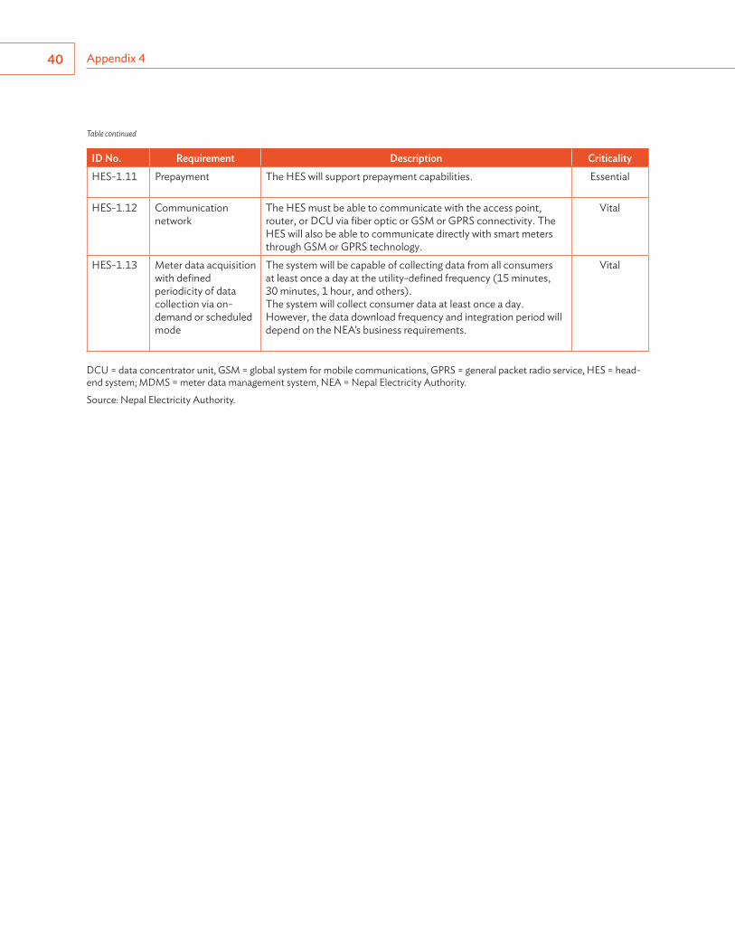
Appendix 440
ID No. Requirement Description CriticalityHES-1.11 Prepayment The HES will support prepayment capabilities. Essential
HES-1.12 Communication network
The HES must be able to communicate with the access point, router, or DCU via fiber optic or GSM or GPRS connectivity. The HES will also be able to communicate directly with smart meters through GSM or GPRS technology.
Vital
HES-1.13 Meter data acquisition with defined periodicity of data collection via on-demand or scheduled mode
The system will be capable of collecting data from all consumers at least once a day at the utility-defined frequency (15 minutes, 30 minutes, 1 hour, and others).The system will collect consumer data at least once a day. However, the data download frequency and integration period will depend on the NEA’s business requirements.
Vital
DCU = data concentrator unit, GSM = global system for mobile communications, GPRS = general packet radio service, HES = head-end system; MDMS = meter data management system, NEA = Nepal Electricity Authority.
Source: Nepal Electricity Authority.
Table continued
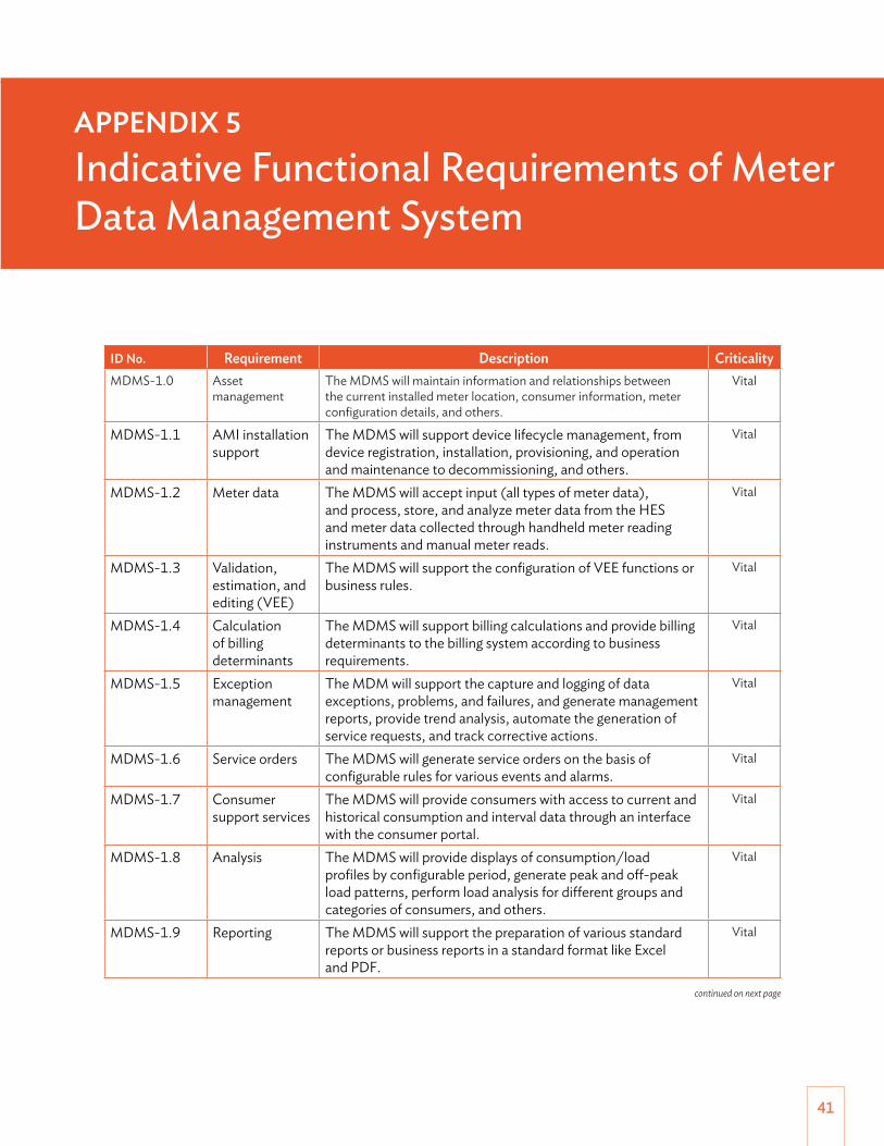
41
ID No. Requirement Description CriticalityMDMS-1.0 Asset
managementThe MDMS will maintain information and relationships between the current installed meter location, consumer information, meter configuration details, and others.
Vital
MDMS-1.1 AMI installation support
The MDMS will support device lifecycle management, from device registration, installation, provisioning, and operation and maintenance to decommissioning, and others.
Vital
MDMS-1.2 Meter data The MDMS will accept input (all types of meter data), and process, store, and analyze meter data from the HES and meter data collected through handheld meter reading instruments and manual meter reads.
Vital
MDMS-1.3 Validation, estimation, and editing (VEE)
The MDMS will support the configuration of VEE functions or business rules.
Vital
MDMS-1.4 Calculation of billing determinants
The MDMS will support billing calculations and provide billing determinants to the billing system according to business requirements.
Vital
MDMS-1.5 Exception management
The MDM will support the capture and logging of data exceptions, problems, and failures, and generate management reports, provide trend analysis, automate the generation of service requests, and track corrective actions.
Vital
MDMS-1.6 Service orders The MDMS will generate service orders on the basis of configurable rules for various events and alarms.
Vital
MDMS-1.7 Consumer support services
The MDMS will provide consumers with access to current and historical consumption and interval data through an interface with the consumer portal.
Vital
MDMS-1.8 Analysis The MDMS will provide displays of consumption/load profiles by configurable period, generate peak and off-peak load patterns, perform load analysis for different groups and categories of consumers, and others.
Vital
MDMS-1.9 Reporting The MDMS will support the preparation of various standard reports or business reports in a standard format like Excel and PDF.
Vital
APPENDIX 5Indicative Functional Requirements of Meter Data Management System
continued on next page
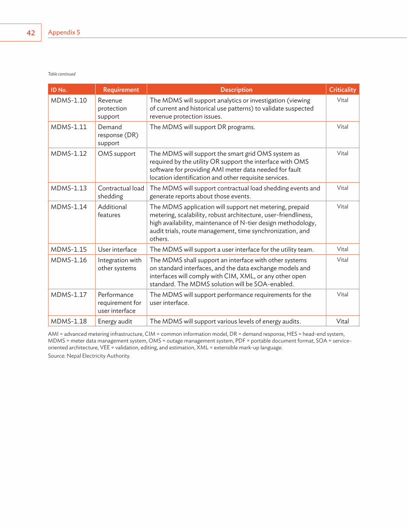
Appendix 542
ID No. Requirement Description CriticalityMDMS-1.10 Revenue
protection support
The MDMS will support analytics or investigation (viewing of current and historical use patterns) to validate suspected revenue protection issues.
Vital
MDMS-1.11 Demand response (DR) support
The MDMS will support DR programs. Vital
MDMS-1.12 OMS support The MDMS will support the smart grid OMS system as required by the utility OR support the interface with OMS software for providing AMI meter data needed for fault location identification and other requisite services.
Vital
MDMS-1.13 Contractual load shedding
The MDMS will support contractual load shedding events and generate reports about those events.
Vital
MDMS-1.14 Additional features
The MDMS application will support net metering, prepaid metering, scalability, robust architecture, user-friendliness, high availability, maintenance of N-tier design methodology, audit trials, route management, time synchronization, and others.
Vital
MDMS-1.15 User interface The MDMS will support a user interface for the utility team. Vital
MDMS-1.16 Integration with other systems
The MDMS shall support an interface with other systems on standard interfaces, and the data exchange models and interfaces will comply with CIM, XML, or any other open standard. The MDMS solution will be SOA-enabled.
Vital
MDMS-1.17 Performance requirement for user interface
The MDMS will support performance requirements for the user interface.
Vital
MDMS-1.18 Energy audit The MDMS will support various levels of energy audits. Vital
AMI = advanced metering infrastructure, CIM = common information model, DR = demand response, HES = head-end system, MDMS = meter data management system, OMS = outage management system, PDF = portable document format, SOA = service-oriented architecture, VEE = validation, editing, and estimation, XML = extensible mark-up language.Source: Nepal Electricity Authority.
Table continued

ASIAN DEVELOPMENT BANK
Smart Metering Road Map for Nepal
This smart metering road map summarizes the proposed activities and plans for the Nepal Electricity Authority on the implementation of a smart electricity grid. Prepared under the Power Transmission and Distribution Efficiency Enhancement Project in Nepal, the road map also explains the guiding principles, decision framework, and methodology used to manage the transition to new technologies.
About the Asian Development Bank
ADB is committed to achieving a prosperous, inclusive, resilient, and sustainable Asia and the Pacific, while sustaining its efforts to eradicate extreme poverty. Established in 1966, it is owned by 67 members— 48 from the region. Its main instruments for helping its developing member countries are policy dialogue, loans, equity investments, guarantees, grants, and technical assistance.
ASIAN DEVELOPMENT BANK6 ADB Avenue, Mandaluyong City1550 Metro Manila, Philippineswww.adb.org
DECEMBER 2018
SMART METERING ROAD MAP FOR NEPAL