Focusing on local solutions smart cities initiatives - Agrion Paris
Smart initiatives in Transmission System
Dr Shekhar Kelapure
PRDC, Bangalore
Page #2 Dr. Shekhar KELAPURE, PRDC, Bangalore
Copyright © 2014 PRDC, Bangalore
Overview
• Introduction
• Objectives
• Challenges
• Technologies
• Conclusions
Page #3 Dr. Shekhar KELAPURE, PRDC, Bangalore
Copyright © 2014 PRDC, Bangalore
Why Smart Transmission Grids (STG) ?
• Improve grid stability
• Reduce energy losses
• Minimize operating cost
• Maximize asset management
• Faster response – Automated control via EMS
• Grid optimization
Page #4 Dr. Shekhar KELAPURE, PRDC, Bangalore
Copyright © 2014 PRDC, Bangalore
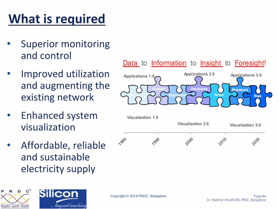
What is required
• Superior monitoring and control
• Improved utilization and augmenting the existing network
• Enhanced system visualization
• Affordable, reliable and sustainable electricity supply
Page #5 Dr. Shekhar KELAPURE, PRDC, Bangalore
Copyright © 2014 PRDC, Bangalore
STG - Features
• Interoperability
• Self-healing
• Reliability
• Fast Acting/Responsive
• Two-way Communication
• Cyber-security and big-data analytics
• Improved Situational awareness

Page #6 Dr. Shekhar KELAPURE, PRDC, Bangalore
Copyright © 2014 PRDC, Bangalore
Technologies that will help us achieve these Objectives
• Improve grid stability
• Reduce energy losses
• Minimize operating cost
• Maximize asset management
• Faster response
– Automated control via EMS
• Grid optimization
Page #7 Dr. Shekhar KELAPURE, PRDC, Bangalore
Copyright © 2014 PRDC, Bangalore
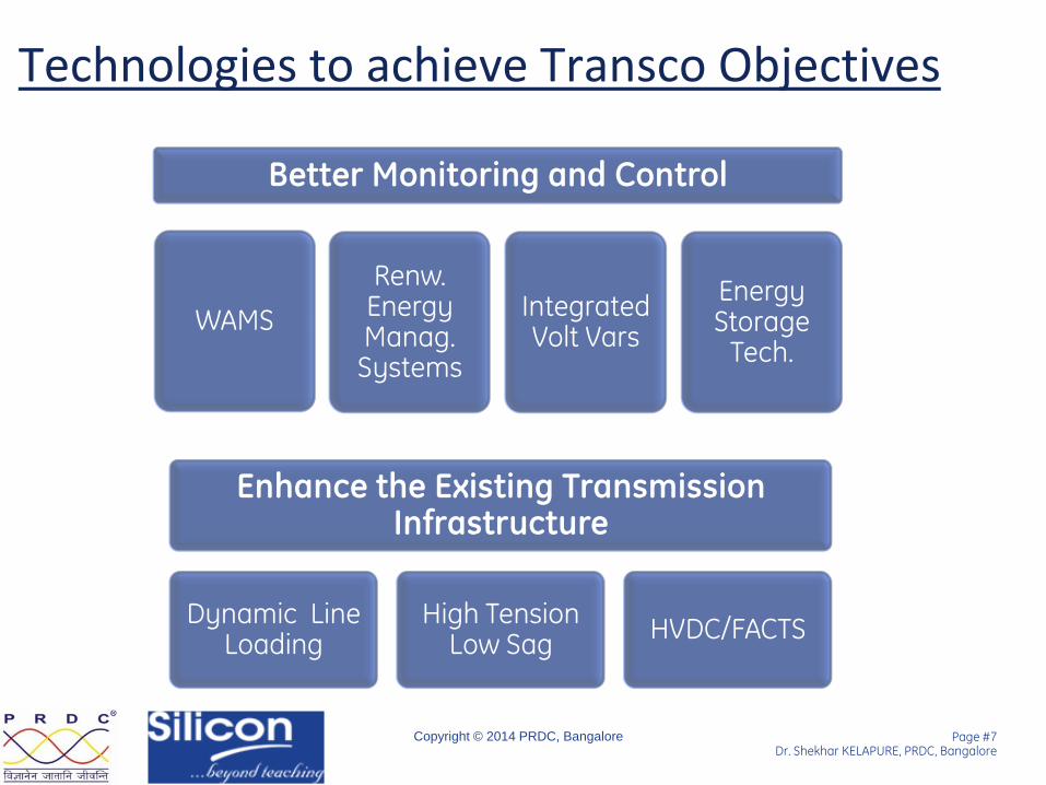
Technologies to achieve Transco Objectives
Better Monitoring and Control
WAMS
Renw. Energy Manag. Systems
Integrated Volt Vars
Energy Storage
Tech.
Enhance the Existing Transmission Infrastructure
Dynamic Line Loading
High Tension Low Sag
HVDC/FACTS

Page #8 Dr. Shekhar KELAPURE, PRDC, Bangalore
Copyright © 2014 PRDC, Bangalore
Technologies 1. Dynamic Line rating
2. High temperature Low sag conductors
3. Integrated Volt-VAR
4. High Voltage DC Systems
5. Wide Area Monitoring Systems (WAMS) - Key
6. Renewable Energy Management System
7. Energy Storage Technologies
8. UHV AC – 800kV and 1200kV
9. City Monitoring System
10. Automated Fault Analysis System
Page #9 Dr. Shekhar KELAPURE, PRDC, Bangalore
Copyright © 2014 PRDC, Bangalore
Dynamic Line rating
• Line rating depends on
→ ambient temperature
→ conductor clearance to ground
→ wind speed and direction
→ solar radiation, etc.
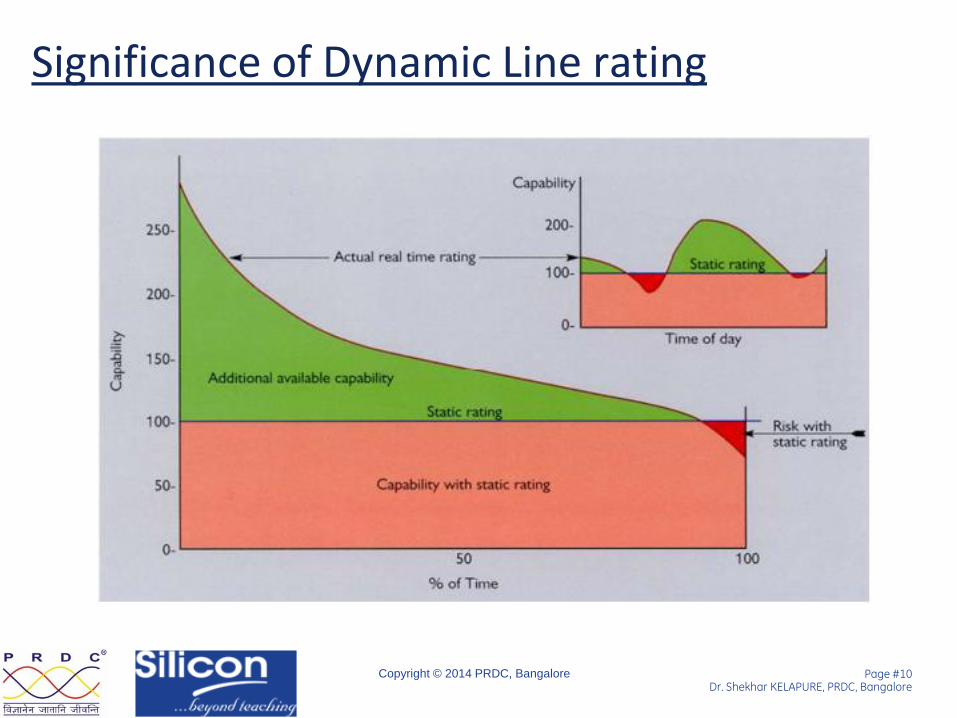
• Having static line ratings lead to under-utilization of line (though the winds safely permit)
• Small weather changes greatly impact ampacity
Page #10 Dr. Shekhar KELAPURE, PRDC, Bangalore
Copyright © 2014 PRDC, Bangalore
Significance of Dynamic Line rating
Page #11 Dr. Shekhar KELAPURE, PRDC, Bangalore
Copyright © 2014 PRDC, Bangalore
How does it Work?
» Remote sensing of transmission line tension/sag is carried out by the monitoring systems and this signal is sent to the utility’s SCADA or EMS.
» Based on this data, continuous updation of the Tr. Lines varying ampacity is done.
» Thereby its rating updated.
Page #12 Dr. Shekhar KELAPURE, PRDC, Bangalore
Copyright © 2014 PRDC, Bangalore
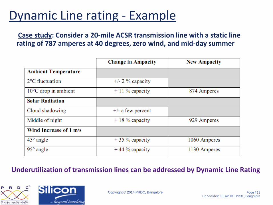
Dynamic Line rating - Example
Case study: Consider a 20-mile ACSR transmission line with a static line rating of 787 amperes at 40 degrees, zero wind, and mid-day summer
Underutilization of transmission lines can be addressed by Dynamic Line Rating

Page #13 Dr. Shekhar KELAPURE, PRDC, Bangalore
Copyright © 2014 PRDC, Bangalore
Dynamic Line rating – Benefits
• Congestion relief
• Asset protection
• Increased wind and solar integration
• Wide area situational awareness
• Reducing wind energy curtailment
• Transmission efficiency
• Avoidance of network expansion to the extent possible

Page #14 Dr. Shekhar KELAPURE, PRDC, Bangalore
Copyright © 2014 PRDC, Bangalore
Technologies 1. Dynamic Line rating
2. High temperature Low sag conductors
3. Integrated Volt-VAR
4. High Voltage DC Systems
5. Wide Area Monitoring Systems (WAMS) - Key
6. Renewable Energy Management System
7. Energy Storage Technologies
8. UHV AC – 800kV and 1200kV
9. City Monitoring System
10. Automated Fault Analysis System
Page #15 Dr. Shekhar KELAPURE, PRDC, Bangalore
Copyright © 2014 PRDC, Bangalore
High sag , legacy
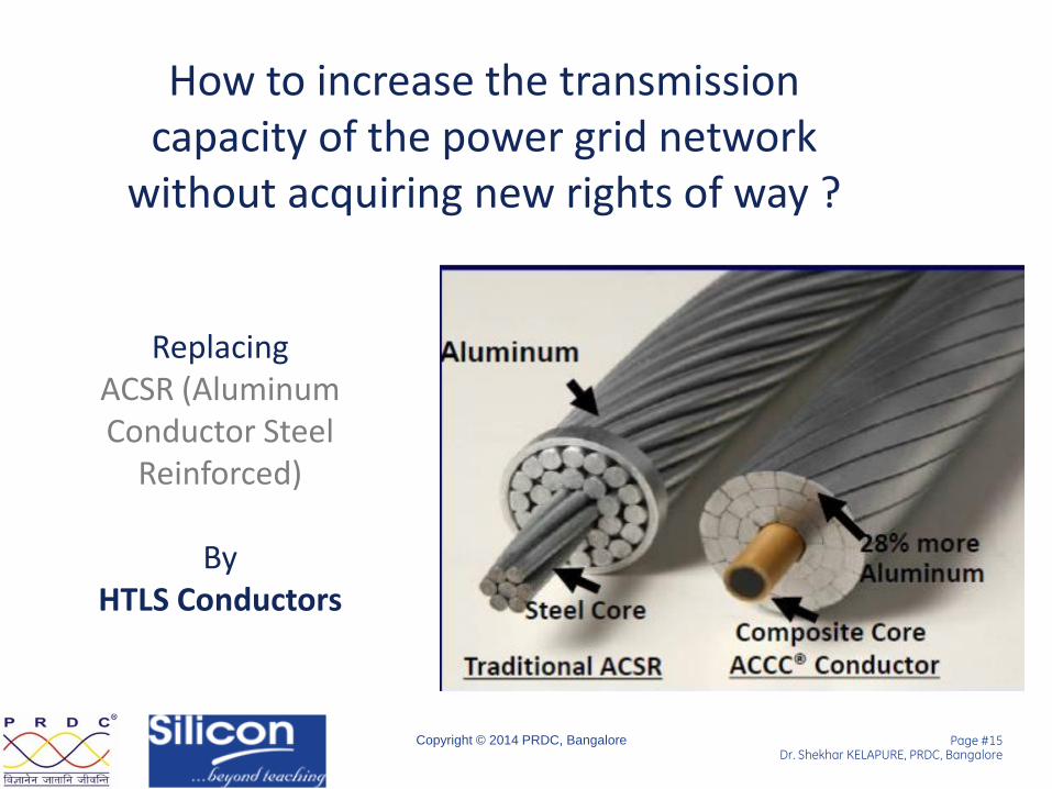
How to increase the transmission capacity of the power grid network
without acquiring new rights of way ?
Replacing ACSR (Aluminum Conductor Steel
Reinforced)
By HTLS Conductors
Page #16 Dr. Shekhar KELAPURE, PRDC, Bangalore
Copyright © 2014 PRDC, Bangalore
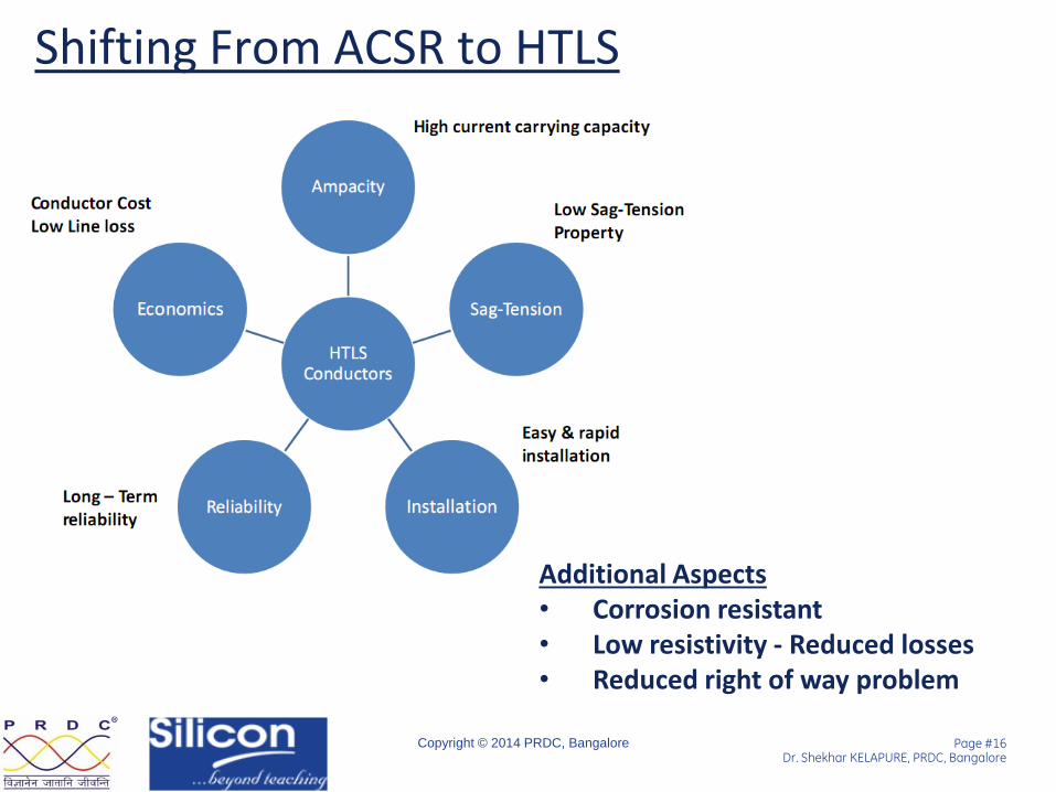
Shifting From ACSR to HTLS
Additional Aspects • Corrosion resistant • Low resistivity - Reduced losses • Reduced right of way problem
Page #17 Dr. Shekhar KELAPURE, PRDC, Bangalore
Copyright © 2014 PRDC, Bangalore
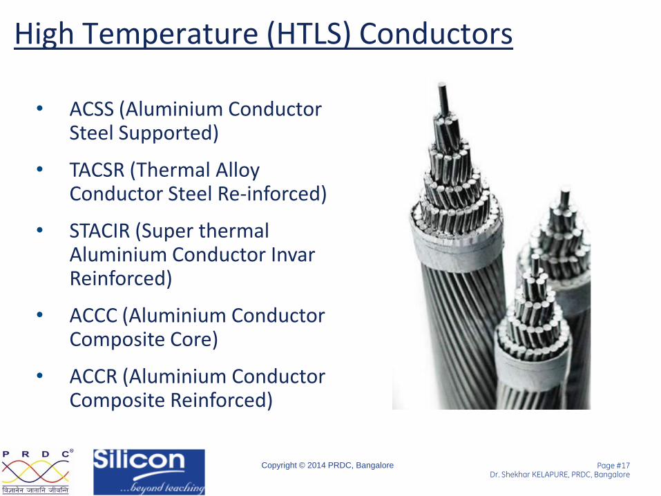
High Temperature (HTLS) Conductors
• ACSS (Aluminium Conductor Steel Supported)
• TACSR (Thermal Alloy Conductor Steel Re-inforced)
• STACIR (Super thermal Aluminium Conductor Invar Reinforced)
• ACCC (Aluminium Conductor Composite Core)
• ACCR (Aluminium Conductor Composite Reinforced)

Page #18 Dr. Shekhar KELAPURE, PRDC, Bangalore
Copyright © 2014 PRDC, Bangalore
HTLS - Performance composition
Page #19 Dr. Shekhar KELAPURE, PRDC, Bangalore
Copyright © 2014 PRDC, Bangalore
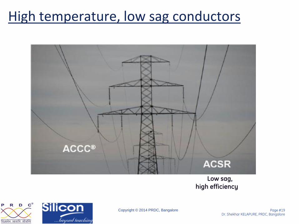
High temperature, low sag conductors
Low sag,
high efficiency

Page #20 Dr. Shekhar KELAPURE, PRDC, Bangalore
Copyright © 2014 PRDC, Bangalore
HTLS - Comparison
Low sag ,
high efficiency
High sag , legacy
Page #21 Dr. Shekhar KELAPURE, PRDC, Bangalore
Copyright © 2014 PRDC, Bangalore
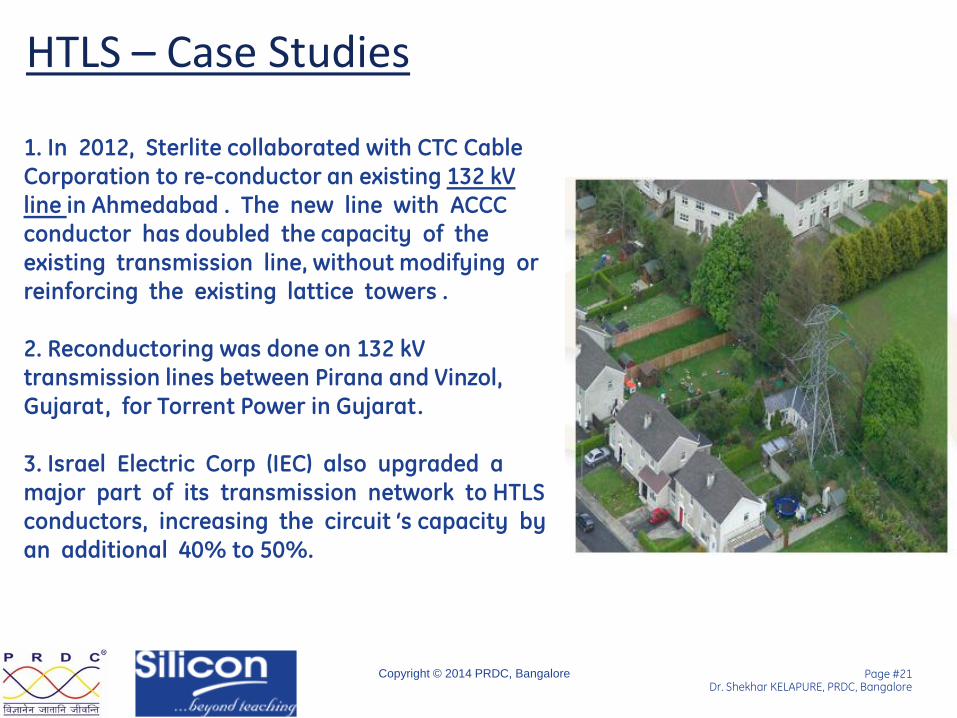
HTLS – Case Studies
Low sag ,
high efficiency
High sag , legacy
1. In 2012, Sterlite collaborated with CTC Cable Corporation to re-conductor an existing 132 kV line in Ahmedabad . The new line with ACCC conductor has doubled the capacity of the existing transmission line, without modifying or reinforcing the existing lattice towers . 2. Reconductoring was done on 132 kV transmission lines between Pirana and Vinzol, Gujarat, for Torrent Power in Gujarat.
3. Israel Electric Corp (IEC) also upgraded a major part of its transmission network to HTLS conductors, increasing the circuit ‘s capacity by an additional 40% to 50%.

Page #22 Dr. Shekhar KELAPURE, PRDC, Bangalore
Copyright © 2014 PRDC, Bangalore
Technologies 1. Dynamic Line rating
2. High temperature Low sag conductors
3. Integrated Volt-VAR
4. High Voltage DC Systems
5. Wide Area Monitoring Systems (WAMS) - Key
6. Renewable Energy Management System
7. Energy Storage Technologies
8. UHV AC – 800kV and 1200kV
9. City Monitoring System
10. Automated Fault Analysis System
Page #23 Dr. Shekhar KELAPURE, PRDC, Bangalore
Copyright © 2014 PRDC, Bangalore
Reactive power based challenges
• Increasingly diversified generation sources (renewables and gas turbines) are changing the power systems in both system topologies and operation strategies.
• This lead to higher pressure for optimization of various VAR sources, esp. dynamic ones.
• The value of future reactive power resources are critical to utility planners.
Page #24 Dr. Shekhar KELAPURE, PRDC, Bangalore
Copyright © 2014 PRDC, Bangalore
Objective
Evaluating integrated volt Var systems, to mitigate the voltage related problems.

Page #25 Dr. Shekhar KELAPURE, PRDC, Bangalore
Copyright © 2014 PRDC, Bangalore
VAR Value Assessment
Pq trade off
Page #26 Dr. Shekhar KELAPURE, PRDC, Bangalore
Copyright © 2014 PRDC, Bangalore
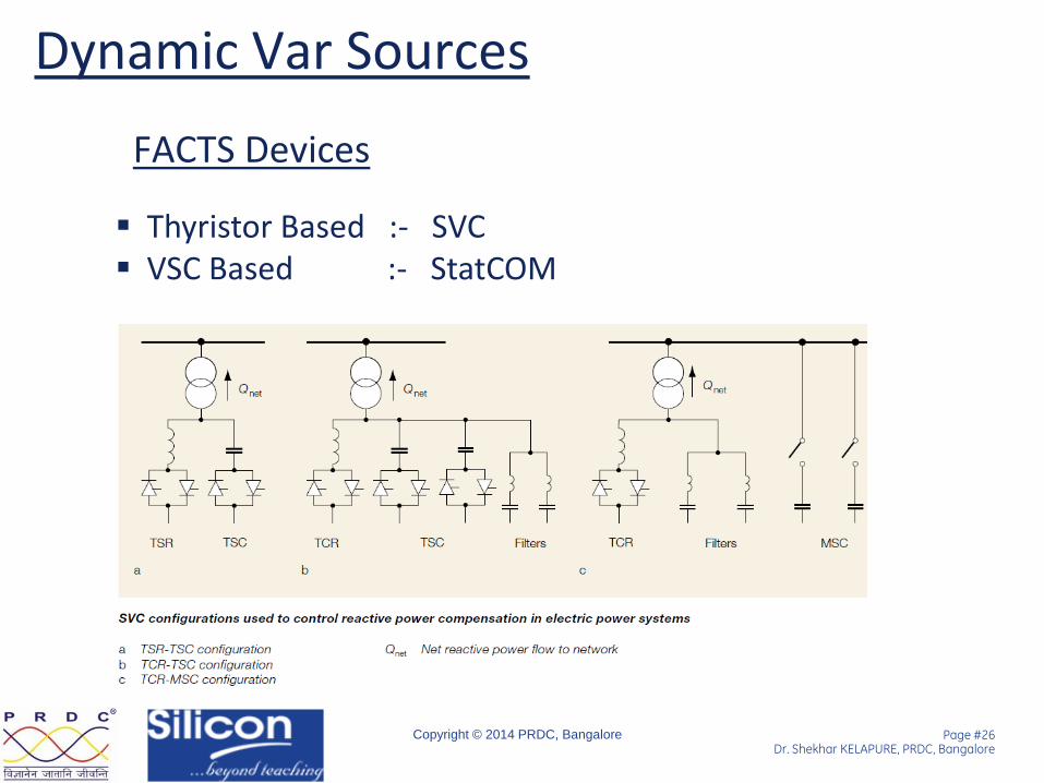
Dynamic Var Sources
FACTS Devices
Thyristor Based :- SVC VSC Based :- StatCOM
Page #27 Dr. Shekhar KELAPURE, PRDC, Bangalore
Copyright © 2014 PRDC, Bangalore
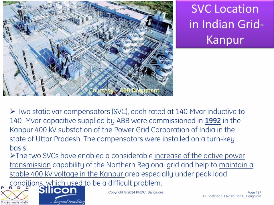
SVC Location in Indian Grid-
Kanpur
The two SVCs have enabled a considerable increase of the active power transmission capability of the Northern Regional grid and help to maintain a stable 400 kV voltage in the Kanpur area especially under peak load conditions, which used to be a difficult problem.
Courtesy – ABB Document
Two static var compensators (SVC), each rated at 140 Mvar inductive to 140 Mvar capacitive supplied by ABB were commissioned in 1992 in the Kanpur 400 kV substation of the Power Grid Corporation of India in the state of Uttar Pradesh. The compensators were installed on a turn-key basis.
Page #28 Dr. Shekhar KELAPURE, PRDC, Bangalore
Copyright © 2014 PRDC, Bangalore
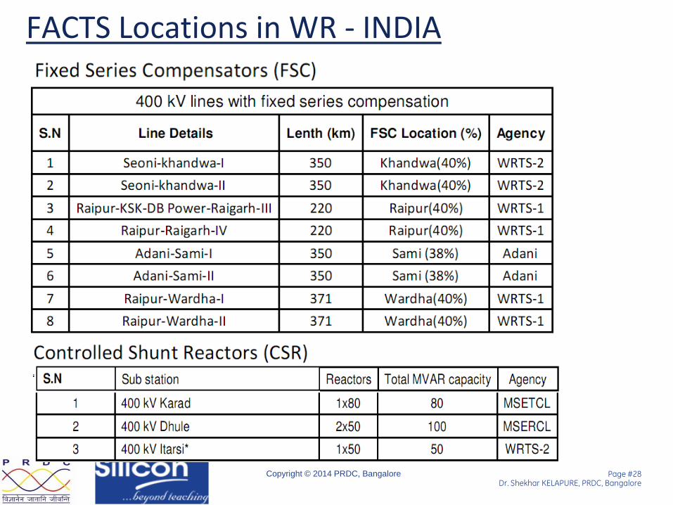
FACTS Locations in WR - INDIA

Page #29 Dr. Shekhar KELAPURE, PRDC, Bangalore
Copyright © 2014 PRDC, Bangalore
FACTS Devices - Benefits
Source: IEEE PES Chapter – Jay Giri
Page #30 Dr. Shekhar KELAPURE, PRDC, Bangalore
Copyright © 2014 PRDC, Bangalore
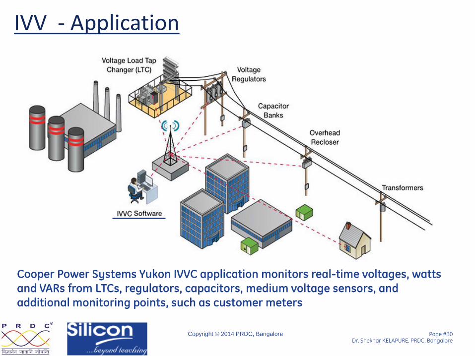
Cooper Power Systems Yukon IVVC application monitors real-time voltages, watts and VARs from LTCs, regulators, capacitors, medium voltage sensors, and
additional monitoring points, such as customer meters
IVV - Application
Page #31 Dr. Shekhar KELAPURE, PRDC, Bangalore
Copyright © 2014 PRDC, Bangalore
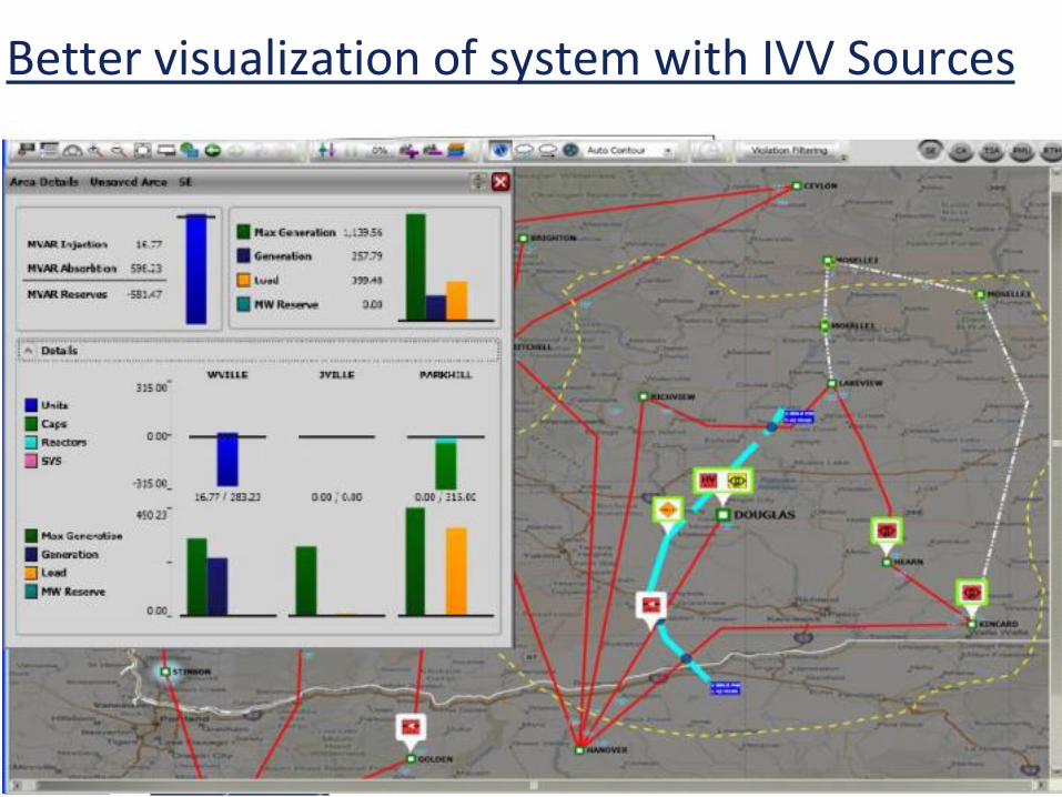
Better visualization of system with IVV Sources

Page #32 Dr. Shekhar KELAPURE, PRDC, Bangalore
Copyright © 2014 PRDC, Bangalore
Technologies 1. Dynamic Line rating
2. High temperature Low sag conductors
3. Integrated Volt-VAR
4. High Voltage DC Systems
5. Wide Area Monitoring Systems (WAMS) - Key
6. Renewable Energy Management System
7. Energy Storage Technologies
8. UHV AC – 800kV and 1200kV
9. City Monitoring System
10. Automated Fault Analysis System

Page #33 Dr. Shekhar KELAPURE, PRDC, Bangalore
Copyright © 2014 PRDC, Bangalore
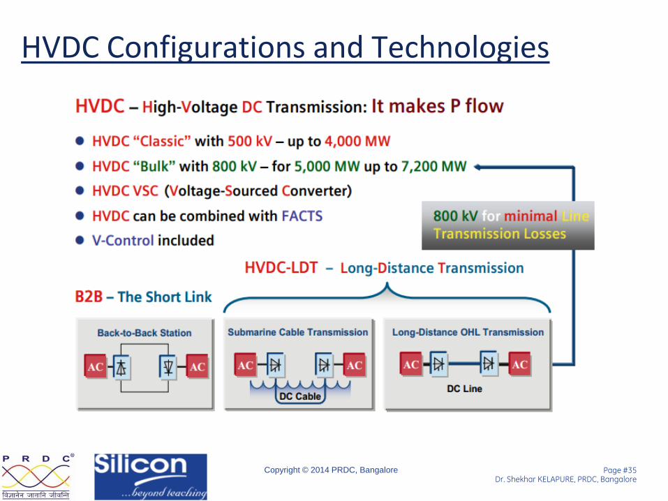
Technical HVDC advantages
• The HVDC power flow is fully controllable, fast and accurate.
• An HVDC link is asynchronous and can adapt to any rated voltage and frequency at reception.
• The HVDC link can be used to assist the AC networks at each end of the link
• HVDC links do not increase the systems short circuit level and fault cannot transfer across HVDC interconnected systems.
Page #34 Dr. Shekhar KELAPURE, PRDC, Bangalore
Copyright © 2014 PRDC, Bangalore
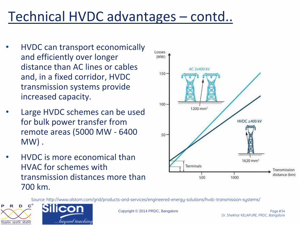
Technical HVDC advantages – contd..
• HVDC can transport economically and efficiently over longer distance than AC lines or cables and, in a fixed corridor, HVDC transmission systems provide increased capacity.
• Large HVDC schemes can be used for bulk power transfer from remote areas (5000 MW - 6400 MW) .
• HVDC is more economical than HVAC for schemes with transmission distances more than 700 km.
Source: http://www.alstom.com/grid/products-and-services/engineered-energy-solutions/hvdc-transmission-systems/
Page #35 Dr. Shekhar KELAPURE, PRDC, Bangalore
Copyright © 2014 PRDC, Bangalore
HVDC Configurations and Technologies

Page #36 Dr. Shekhar KELAPURE, PRDC, Bangalore
Copyright © 2014 PRDC, Bangalore
HVDC installations in India
NR-NR
WR-WR
NR
NR-ER

Page #37 Dr. Shekhar KELAPURE, PRDC, Bangalore
Copyright © 2014 PRDC, Bangalore
Few HVDC – International Installations
Bheramara India - Bangladesh 2013 B/B 500MW
Page #38 Dr. Shekhar KELAPURE, PRDC, Bangalore
Copyright © 2014 PRDC, Bangalore
HVDC- Benefits
• Enhance AC Grid Voltage and angular stability
• Inter-area Oscillations Damping
• Provide dynamic voltage support
• Sub synchronous damping control
• Get operational intelligence and exploring/more on hvdc capability
• Lower losses (no skin effect)
• Better Utilization of Transmission line
• Asynchronous power systems connection
• Lower cost for large distance transmission
Page #39 Dr. Shekhar KELAPURE, PRDC, Bangalore
Copyright © 2014 PRDC, Bangalore
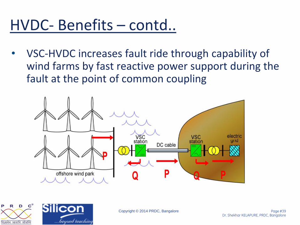
HVDC- Benefits – contd..
• VSC-HVDC increases fault ride through capability of wind farms by fast reactive power support during the fault at the point of common coupling
Page #40 Dr. Shekhar KELAPURE, PRDC, Bangalore
Copyright © 2014 PRDC, Bangalore
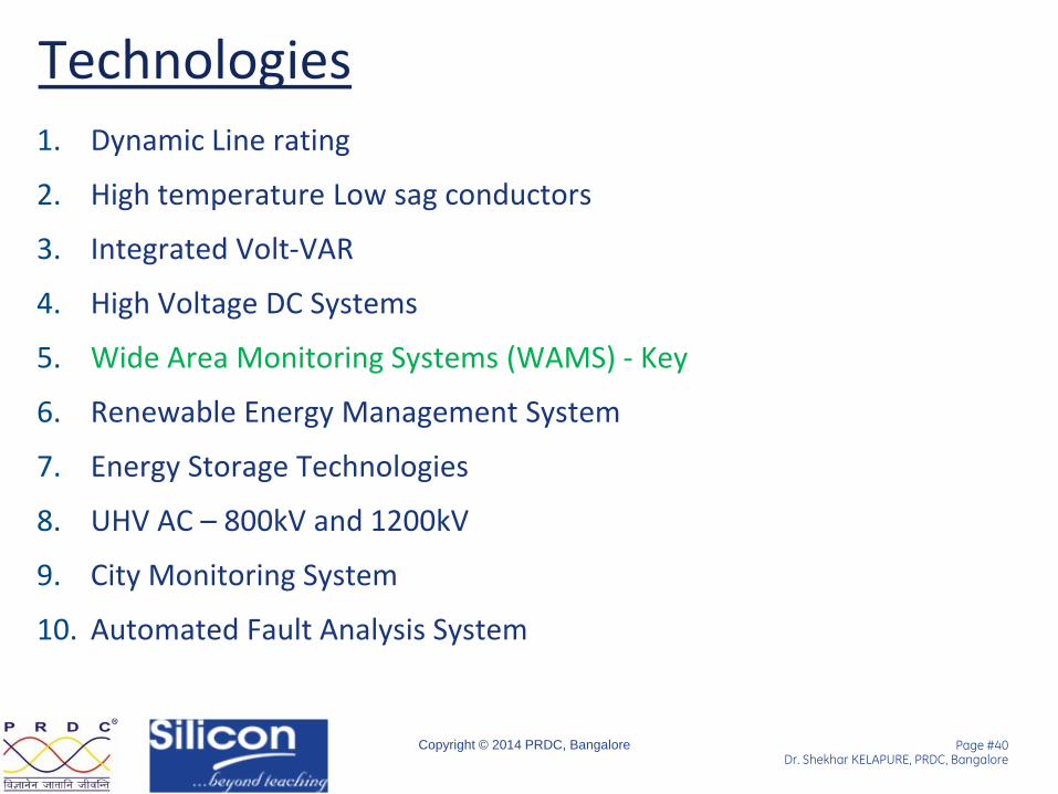
Technologies 1. Dynamic Line rating
2. High temperature Low sag conductors
3. Integrated Volt-VAR
4. High Voltage DC Systems
5. Wide Area Monitoring Systems (WAMS) - Key
6. Renewable Energy Management System
7. Energy Storage Technologies
8. UHV AC – 800kV and 1200kV
9. City Monitoring System
10. Automated Fault Analysis System
Page #41 Dr. Shekhar KELAPURE, PRDC, Bangalore
Copyright © 2014 PRDC, Bangalore
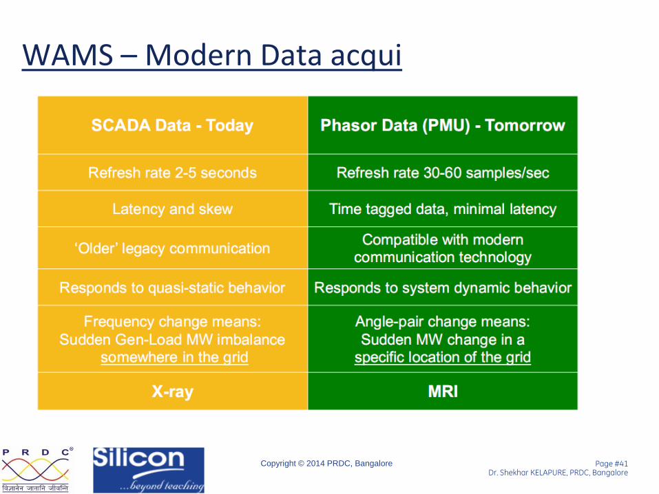
WAMS – Modern Data acqui

Page #42 Dr. Shekhar KELAPURE, PRDC, Bangalore
Copyright © 2014 PRDC, Bangalore
Enhanced Situational Awareness in the Control Room
Page #43 Dr. Shekhar KELAPURE, PRDC, Bangalore
Copyright © 2014 PRDC, Bangalore
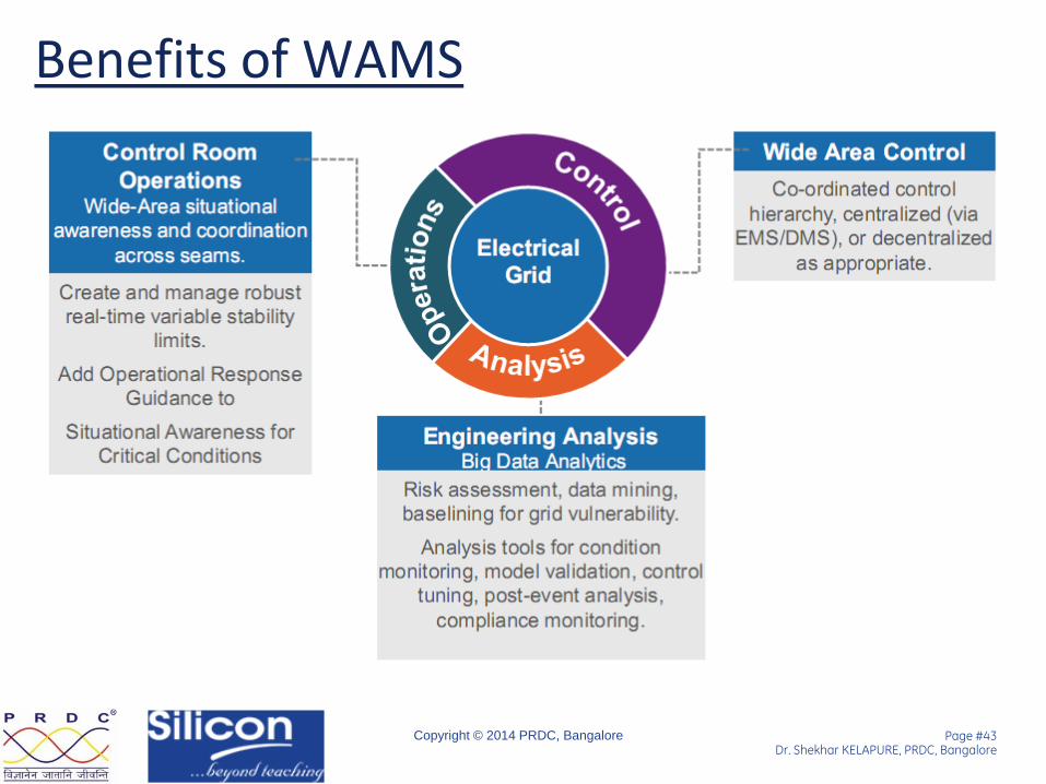
Benefits of WAMS
Page #44 Dr. Shekhar KELAPURE, PRDC, Bangalore
Copyright © 2014 PRDC, Bangalore
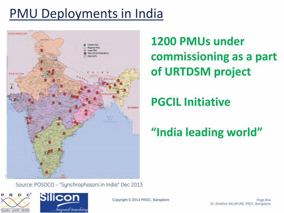
PMU Deployments in India
Source: POSOCO – “Synchrophasors in India” Dec 2013
1200 PMUs under commissioning as a part of URTDSM project PGCIL Initiative “India leading world”

Page #45 Dr. Shekhar KELAPURE, PRDC, Bangalore
Copyright © 2014 PRDC, Bangalore
Phasor Analytics – Some tools

Page #46 Dr. Shekhar KELAPURE, PRDC, Bangalore
Copyright © 2014 PRDC, Bangalore
Technologies 1. Dynamic Line rating
2. High temperature Low sag conductors
3. Integrated Volt-VAR
4. High Voltage DC Systems
5. Wide Area Monitoring Systems (WAMS) - Key
6. Renewable Energy Management System
7. Energy Storage Technologies
8. UHV AC – 800kV and 1200kV
9. City Monitoring System
10. Automated Fault Analysis System
Page #47 Dr. Shekhar KELAPURE, PRDC, Bangalore
Copyright © 2014 PRDC, Bangalore
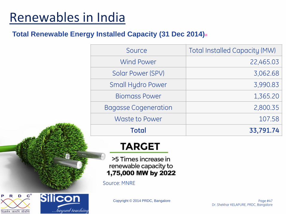
Renewables in India
Source Total Installed Capacity (MW)
Wind Power 22,465.03
Solar Power (SPV) 3,062.68
Small Hydro Power 3,990.83
Biomass Power 1,365.20
Bagasse Cogeneration 2,800.35
Waste to Power 107.58
Total 33,791.74
Total Renewable Energy Installed Capacity (31 Dec 2014)[3]
Source: MNRE

Page #48 Dr. Shekhar KELAPURE, PRDC, Bangalore
Copyright © 2014 PRDC, Bangalore
Issues in Large Scale Renewable Integration
• Intermittent and unpredictable
• RE plants providing lesser reactive grid support during disturbances
• Most of the wind plants are not Fault Ride Through (FRT) capable
• Voltage Excursions at different loadings
• Evacuation challenges
Page #49 Dr. Shekhar KELAPURE, PRDC, Bangalore
Copyright © 2014 PRDC, Bangalore
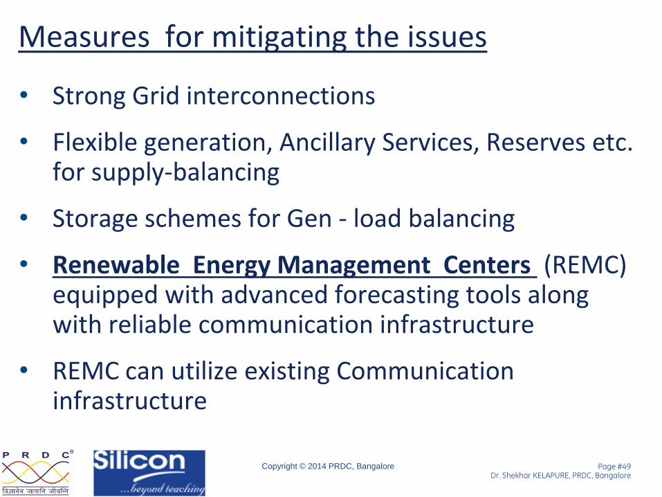
Measures for mitigating the issues
• Strong Grid interconnections
• Flexible generation, Ancillary Services, Reserves etc. for supply-balancing
• Storage schemes for Gen - load balancing
• Renewable Energy Management Centers (REMC) equipped with advanced forecasting tools along with reliable communication infrastructure
• REMC can utilize existing Communication infrastructure
Page #50 Dr. Shekhar KELAPURE, PRDC, Bangalore
Copyright © 2014 PRDC, Bangalore
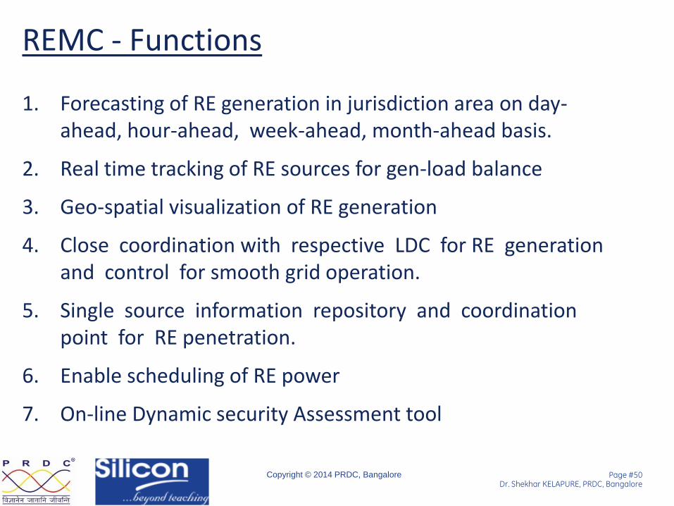
REMC - Functions
1. Forecasting of RE generation in jurisdiction area on day-ahead, hour-ahead, week-ahead, month-ahead basis.
2. Real time tracking of RE sources for gen-load balance
3. Geo-spatial visualization of RE generation
4. Close coordination with respective LDC for RE generation and control for smooth grid operation.
5. Single source information repository and coordination point for RE penetration.
6. Enable scheduling of RE power
7. On-line Dynamic security Assessment tool

Page #51 Dr. Shekhar KELAPURE, PRDC, Bangalore
Copyright © 2014 PRDC, Bangalore
REMC –Architecture
Page #52 Dr. Shekhar KELAPURE, PRDC, Bangalore
Copyright © 2014 PRDC, Bangalore
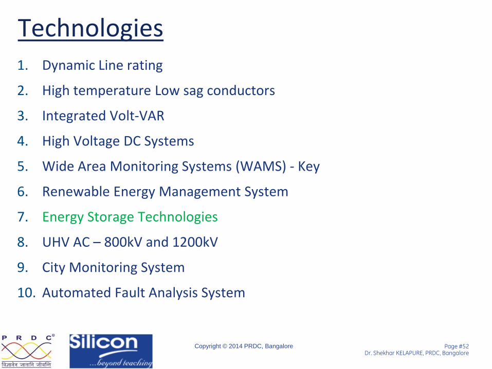
Technologies 1. Dynamic Line rating
2. High temperature Low sag conductors
3. Integrated Volt-VAR
4. High Voltage DC Systems
5. Wide Area Monitoring Systems (WAMS) - Key
6. Renewable Energy Management System
7. Energy Storage Technologies
8. UHV AC – 800kV and 1200kV
9. City Monitoring System
10. Automated Fault Analysis System
Page #53 Dr. Shekhar KELAPURE, PRDC, Bangalore
Copyright © 2014 PRDC, Bangalore
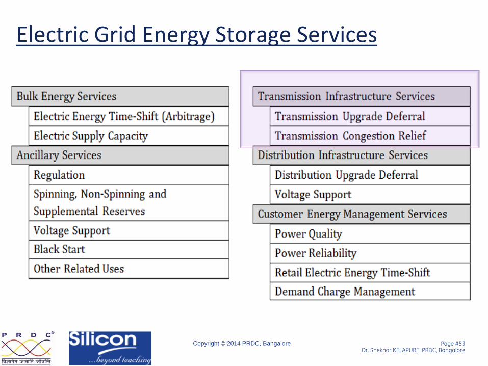
Electric Grid Energy Storage Services
Page #54 Dr. Shekhar KELAPURE, PRDC, Bangalore
Copyright © 2014 PRDC, Bangalore
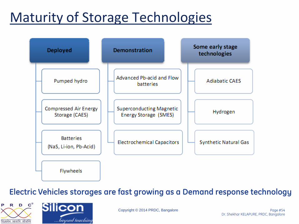
Maturity of Storage Technologies
Electric Vehicles storages are fast growing as a Demand response technology

Page #55 Dr. Shekhar KELAPURE, PRDC, Bangalore
Copyright © 2014 PRDC, Bangalore
Storage - Advantages and Disadvantages
Page #56 Dr. Shekhar KELAPURE, PRDC, Bangalore
Copyright © 2014 PRDC, Bangalore
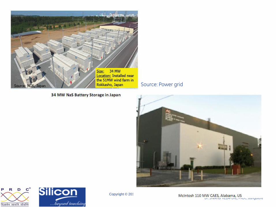
Source: Power grid
Page #57 Dr. Shekhar KELAPURE, PRDC, Bangalore
Copyright © 2014 PRDC, Bangalore
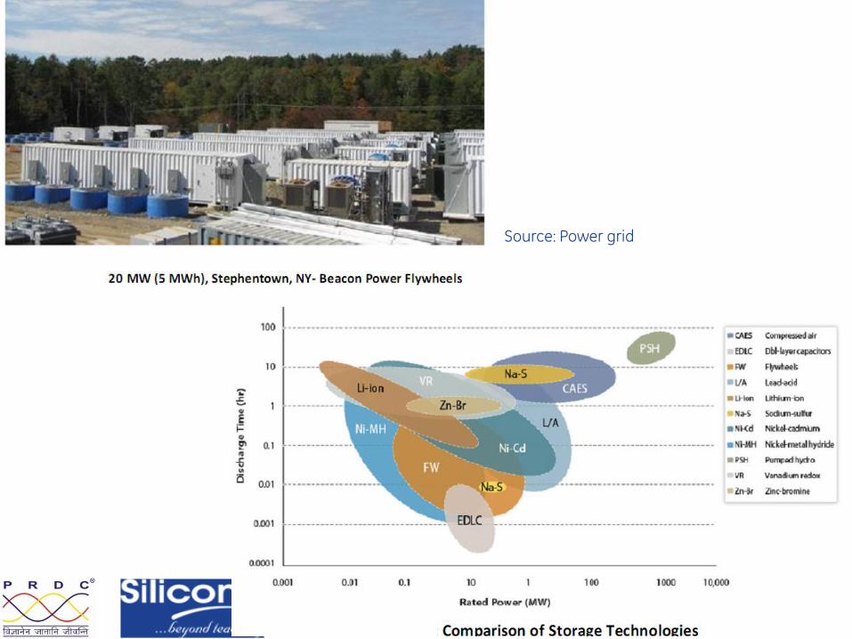
Source: Power grid
Page #58 Dr. Shekhar KELAPURE, PRDC, Bangalore
Copyright © 2014 PRDC, Bangalore
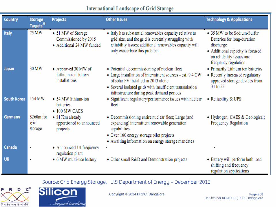
Source: Grid Energy Storage, U.S Department of Energy – December 2013
Page #59 Dr. Shekhar KELAPURE, PRDC, Bangalore
Copyright © 2014 PRDC, Bangalore
Technologies 1. Dynamic Line rating
2. High temperature Low sag conductors
3. Integrated Volt-VAR
4. High Voltage DC Systems
5. Wide Area Monitoring Systems (WAMS) - Key
6. Renewable Energy Management System
7. Energy Storage Technologies
8. UHV AC – 800kV and 1200kV
9. City Monitoring System
10. Automated Fault Analysis System
Page #60 Dr. Shekhar KELAPURE, PRDC, Bangalore
Copyright © 2014 PRDC, Bangalore
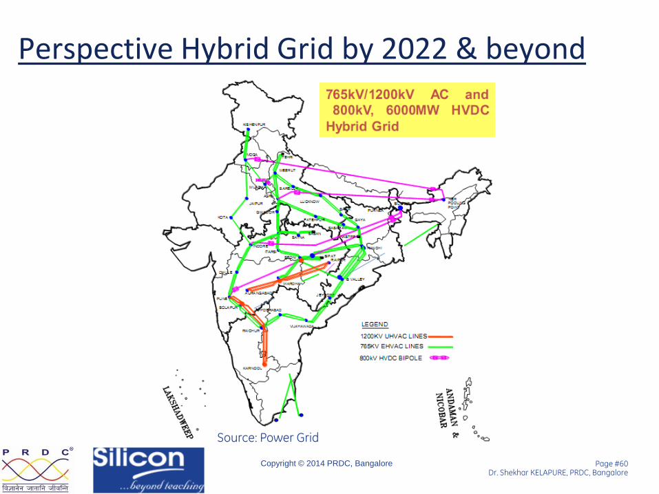
Perspective Hybrid Grid by 2022 & beyond
Source: Power Grid
Page #61 Dr. Shekhar KELAPURE, PRDC, Bangalore
Copyright © 2014 PRDC, Bangalore
1200 kV introduced
• 1200kV test line commissioned at Bina and handed over to Nation
• Deoli near Wardha will be the first 1200 kV commercial line – wrong data –t be checked
• Deoli–Aurangabad line will be second 400/1200kV substations are planned at Deoli and Aurangabad
Page #62 Dr. Shekhar KELAPURE, PRDC, Bangalore
Copyright © 2014 PRDC, Bangalore
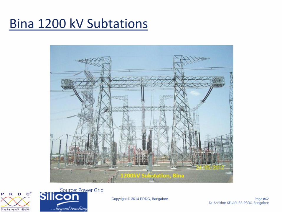
Bina 1200 kV Subtations
Source: Power Grid
Page #63 Dr. Shekhar KELAPURE, PRDC, Bangalore
Copyright © 2014 PRDC, Bangalore
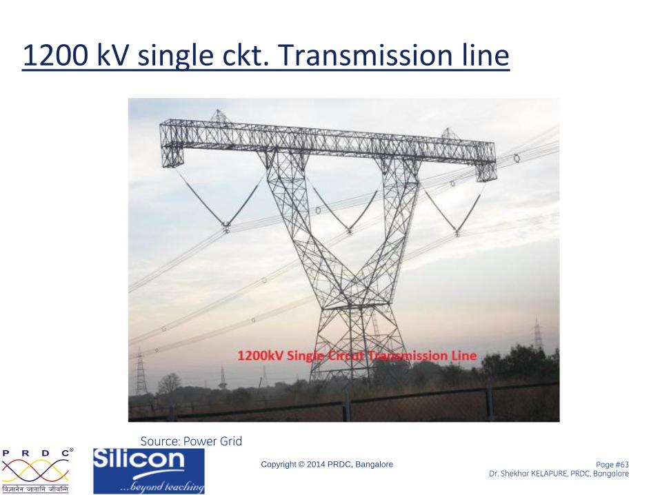
1200 kV single ckt. Transmission line
Source: Power Grid
Page #64 Dr. Shekhar KELAPURE, PRDC, Bangalore
Copyright © 2014 PRDC, Bangalore
Technologies • Dynamic Line rating
• High temperature Low sag conductors
• Integrated Volt-VAR
• High Voltage DC Systems
• Wide Area Monitoring Systems (WAMS) - Key
• Renewable Energy Management System
• Energy Storage Technologies
• UHV AC – 800kV and 1200kV
• City Monitoring System
• Automated Fault Analysis System
Page #65 Dr. Shekhar KELAPURE, PRDC, Bangalore
Copyright © 2014 PRDC, Bangalore
Why CMS
Facilitate the energy audit of the city transmission network, thereby improve the accountability of power injections into the system against the consumption of city areas
Centralized asset management
Remote monitoring and control of substations
Better utilization of substation equipment by providing self diagnostic condition monitoring units
Visualization of comprehensive substation data at city control centre
Better decision making in case of any contingencies
Reduce outage periods
Reduce manpower requirement

Page #66 Dr. Shekhar KELAPURE, PRDC, Bangalore
Copyright © 2014 PRDC, Bangalore
What is CMS
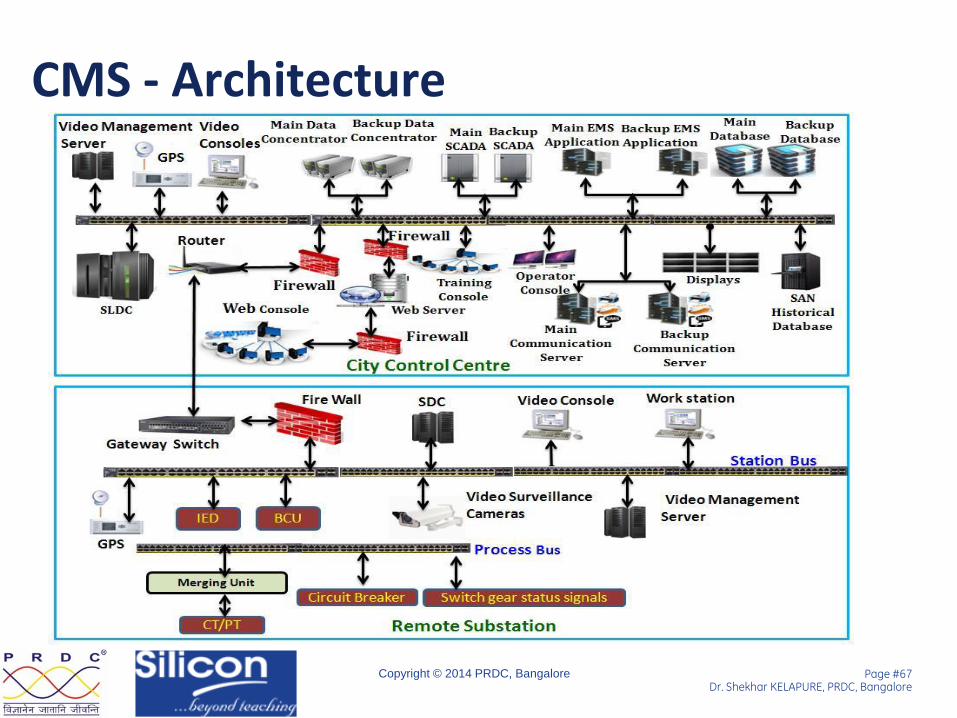
City Monitoring System consists of automated substations in a city, connected to city control centre with the objective of improving the operational as well as process efficiency of the power system network. There are two major components of city monitoring systems. City Control Centre Digital/ Automated substations
Advance measurement, Better visualization, Effective control
Page #67 Dr. Shekhar KELAPURE, PRDC, Bangalore
Copyright © 2014 PRDC, Bangalore
CMS - Architecture
Page #68 Dr. Shekhar KELAPURE, PRDC, Bangalore
Copyright © 2014 PRDC, Bangalore
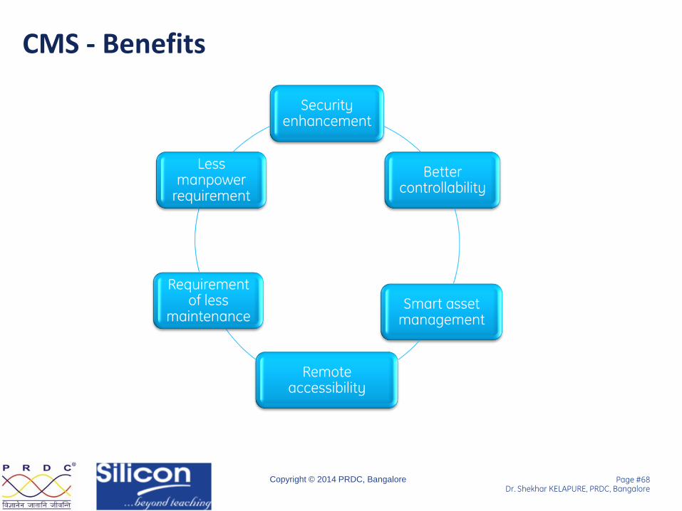
CMS - Benefits
Security enhancement
Better controllability
Smart asset management
Remote accessibility
Requirement of less
maintenance
Less manpower
requirement
Page #69 Dr. Shekhar KELAPURE, PRDC, Bangalore
Copyright © 2014 PRDC, Bangalore
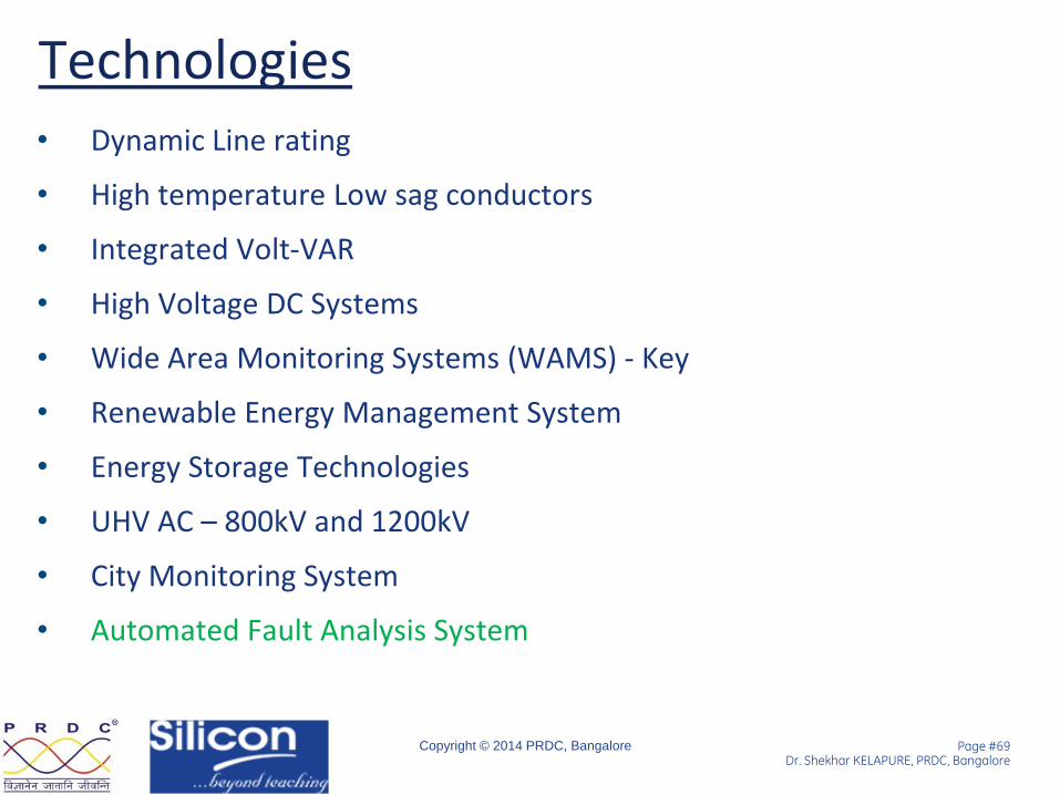
Technologies • Dynamic Line rating
• High temperature Low sag conductors
• Integrated Volt-VAR
• High Voltage DC Systems
• Wide Area Monitoring Systems (WAMS) - Key
• Renewable Energy Management System
• Energy Storage Technologies
• UHV AC – 800kV and 1200kV
• City Monitoring System
• Automated Fault Analysis System
Page #70 Dr. Shekhar KELAPURE, PRDC, Bangalore
Copyright © 2014 PRDC, Bangalore
Why AFAS
Facilitates:
• Automatic retrieval of disturbance files at a common location
• Automatic fault diagnosis, report generation and intimation to concerned personnel
• Substation and system level analysis for a fault
• Better fault location computation and hence facilitates faster fault clearing
AFAS streamlines the process of fault diagnosis
Page #71 Dr. Shekhar KELAPURE, PRDC, Bangalore
Copyright © 2014 PRDC, Bangalore
What is AFAS
Automated Fault Analysis System (AFAS) may be defined as the ability of a specialized computer program to correlate and analyse available data about power system faults and disturbances.
Information extracted from AFAS can be utilized by
Operating personnel
Protection engineers
Maintenance crew
Integrated Approach to Collect, Store and Analyse Data

Page #72 Dr. Shekhar KELAPURE, PRDC, Bangalore
Copyright © 2014 PRDC, Bangalore
AFAS - Process
Processed File
Storage
AFAS
Report
Manager
Data
Collector

Page #73 Dr. Shekhar KELAPURE, PRDC, Bangalore
Copyright © 2014 PRDC, Bangalore
Benefits
• Automated Fault diagnosis and Reporting
• Reduce Outage Time and improve Reliability
• Optimize Man power/ Maintenance cost

Page #74 Dr. Shekhar KELAPURE, PRDC, Bangalore
Copyright © 2014 PRDC, Bangalore
Conclusions
Implementation of the project results in
• Reduction in transmission losses
• Reduction in the number of power cuts – load shedding/ blackouts/ brownouts
• Improved efficiency in operations
• Improved system reliability
• Reduction in the operation and maintenance (O&M) costs
• Shifting from Reactive to Proactive!
Page #75 Dr. Shekhar KELAPURE, PRDC, Bangalore
Copyright © 2014 PRDC, Bangalore
Thank You

Page #76 Dr. Shekhar KELAPURE, PRDC, Bangalore
Copyright © 2014 PRDC, Bangalore
? Dr Shekhar Kelapure
General Manager R&D, PRDC, Bangalore M – 0091 99000 26575, E – [email protected]