Smart Choices for Motor Management - Electric Company · 2014-12-11 · Smart Choices for Motor...
77
Smart Choices for Motor Management A Selection Guide for Smart Motor Controllers
Transcript of Smart Choices for Motor Management - Electric Company · 2014-12-11 · Smart Choices for Motor...
Smart Choices forMotor Management
A Selection Guide for Smart Motor Controllers

Mat
erial H
andl
ing
Cent
rifug
al P
umps
Compr
esso
rs
Over
head
Cra
nes
Conv
eyor
Sys
tems
Stirr
ers
and
Mixer
s
Lumbe
r an
d Sa
w M
ills
Extrud
ers
Allen-Bradley Smart Motor Controllers:Intelligent, Robust, Reliable
A Few FamiliarApplications
SMC PLUS™ Smart Motor ControllerSMC-2™ Smart Motor ControllerSTC™ Starting Torque Controller
As a world leader in industrial control systems, Rockwell Automation
offers a complete line of Allen-BradleySmart Motor Controllers (SMC) designed tomeet the motor management needs of manyapplications. Our robust family of controllersfeatures the reliability of solid state electronicsfor controlling single-and three-phaseinduction motors.
Solid state starting provides smoothacceleration, without the arcing, chattering or vibration problems associated withconventional electromechanical motorstarters. Maintenance costs and productionlosses can be reduced, as can wear on moving parts such as belts, chains, gear boxes, and bearings.
When looking for compact, cost effectivesolutions, STC and SMC-2 controllers areeasy to set up and maintain.

Motor Management:The Essence of Automation
In today’s automated industrial
environments, electric motors handle more
than half the workload, providing the
power for virtually every process involved
in production and manufacturing.
This places a substantial premium on
motor protection and up time.
With the trend toward consolidating
multiple protective functions into a single
motor control device, system performance,
reliability and efficiency can be
significantly enhanced. Solid state
devices offer even greater integration and
functionality, with lower costs for
components, installation and maintenance,
and with smaller control panels.
In short, highly sophisticated motor
management is now available in ways that
were previously too costly or impractical
to consider.
Through device level network
communications, vital motor operating
data can be gathered, processed and
displayed, all at the local level.
Problems can be detected and devices
prevented from tripping at a critical stage
in a process, helping to prevent costly
downtime and unscheduled maintenance.
SMC Dialog Plus™ Controller
Rock
Cru
sher
s
Tran
spor
t Sy
stem
s
Vent
ilato
rs a
nd B
lower
sMills
and
Knea
ders
The SMC Dialog Plus™ controllers offersophisticated performance with advancedmotor protection, networking capabilities andeasy programmability – making it the nextgeneration of intelligent motor control.
And Allen-Bradley SMC PLUS™ and SMCDialog Plus controllers offer a variety ofoptions for soft stopping, slow speedoperation, braking, and pump control,providing exceptional flexibility and motormanagement solutions.

STC Starting TorqueControllersAllen-Bradley STC controllers provide areliable method of reducing unwantedproblems encountered in typical across-the-line starting applications. With smoother
starting of AC induction motors, equipment downtime due to problems relatedto mechanical shock and vibration issubstantially reduced.
1–22 Amps
100–600V AC, 50/60Hz
Soft Start
Digital AdjustmentsCompact Design
Current Range
Voltage Range
Starting Mode
Features
Starting torque surge during DOLor across-the-line motor starting cancause damage to the motor and to thedriven equipment.
The STC controller is effective indecreasing the magnitude of startingtorque surges.
STC controller versus a typicalacross-the-line start.
Time
Torq
ue
Time
Torq
ue
Time
Torq
ue
4
STC
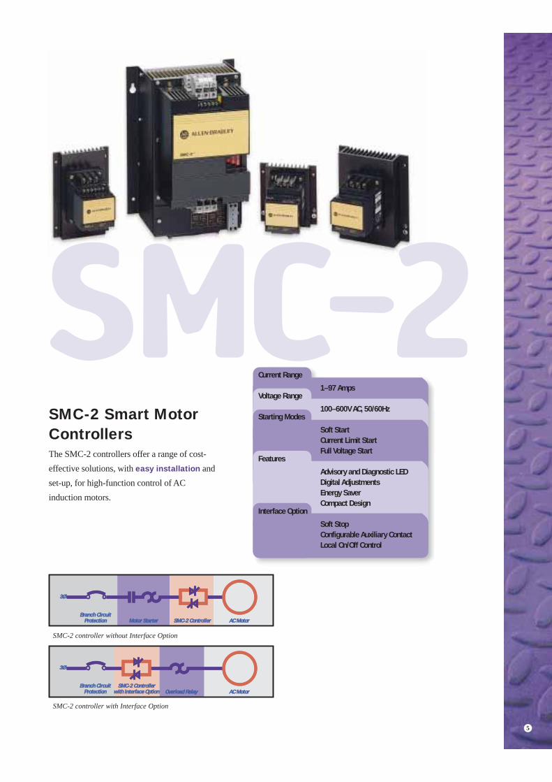
SMC-2 Smart MotorControllersThe SMC-2 controllers offer a range of cost-effective solutions, with easy installation andset-up, for high-function control of ACinduction motors.
1–97 Amps
100–600V AC, 50/60Hz
Soft StartCurrent Limit StartFull Voltage Start
Advisory and Diagnostic LEDDigital AdjustmentsEnergy SaverCompact Design
Soft StopConfigurable Auxiliary ContactLocal On/Off Control
Current Range
Voltage Range
Starting Modes
Features
Interface Option
3Ø3Ø
Branch CircuitBranch CircuitProtectionProtection Motor StarterMotor Starter
Overload RelayOverload Relay
SMC-2 ControllerSMC-2 Controller AC MotorAC Motor
AC MotorAC Motor
3Ø3Ø
Branch CircuitBranch CircuitProtectionProtection
SMC-2 ControllerSMC-2 Controllerwith Interface Optionwith Interface Option
SMC-2 controller without Interface Option
SMC-2 controller with Interface Option
5
SMC-2
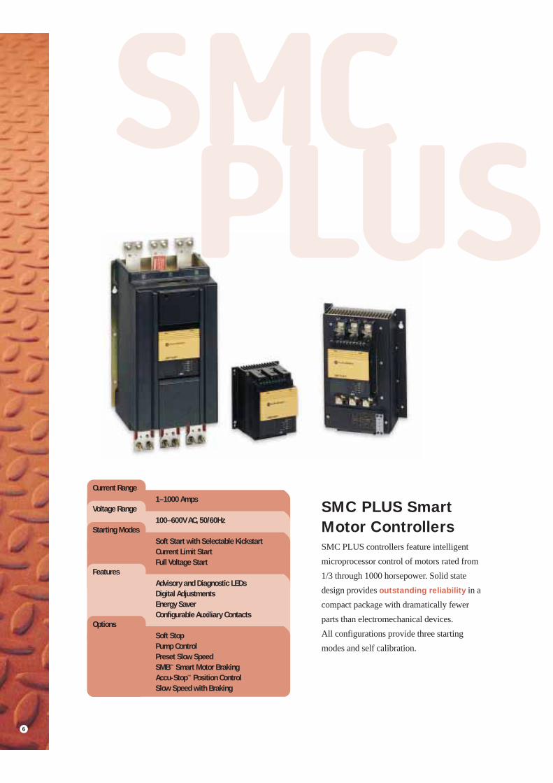
SMC PLUS SmartMotor ControllersSMC PLUS controllers feature intelligentmicroprocessor control of motors rated from1/3 through 1000 horsepower. Solid statedesign provides outstanding reliability in acompact package with dramatically fewer parts than electromechanical devices. All configurations provide three startingmodes and self calibration.
Current Range
Voltage Range
Starting Modes
Features
Options
1–1000 Amps
100–600V AC, 50/60Hz
Soft Start with Selectable KickstartCurrent Limit StartFull Voltage Start
Advisory and Diagnostic LEDsDigital AdjustmentsEnergy SaverConfigurable Auxiliary Contacts
Soft StopPump ControlPreset Slow SpeedSMB™ Smart Motor BrakingAccu-Stop™ Position ControlSlow Speed with Braking
6
SMCPLUS
7
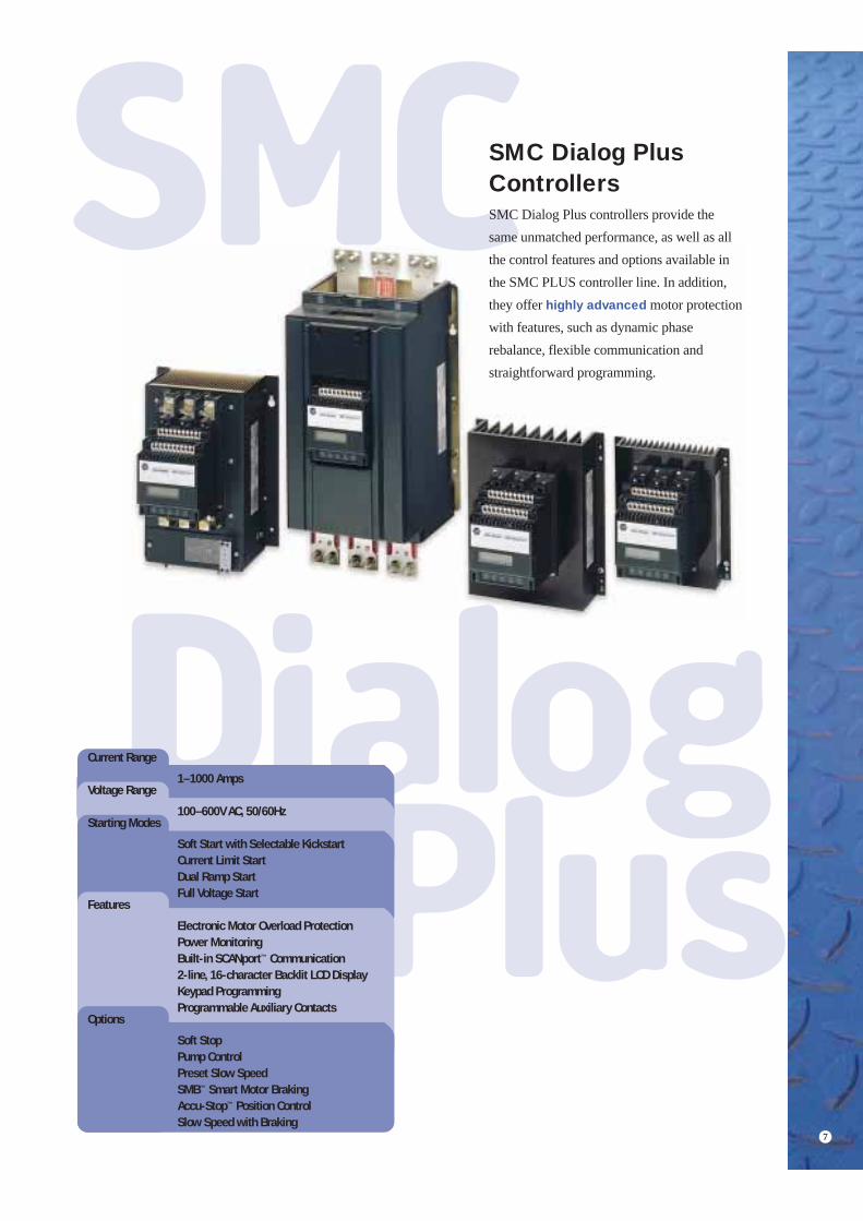
SMC Dialog PlusControllersSMC Dialog Plus controllers provide the same unmatched performance, as well as allthe control features and options available inthe SMC PLUS controller line. In addition,they offer highly advanced motor protectionwith features, such as dynamic phaserebalance, flexible communication andstraightforward programming.
Current Range
Voltage Range
Starting Modes
Features
Options
1–1000 Amps
100–600V AC, 50/60Hz
Soft Start with Selectable KickstartCurrent Limit StartDual Ramp StartFull Voltage Start
Electronic Motor Overload ProtectionPower MonitoringBuilt-in SCANport™ Communication2-line, 16-character Backlit LCD DisplayKeypad ProgrammingProgrammable Auxiliary Contacts
Soft StopPump ControlPreset Slow SpeedSMB™ Smart Motor BrakingAccu-Stop™ Position ControlSlow Speed with Braking

Advanced Motor Management
8
Advanced diagnostics Fault diagnostic capabilities built into the SMC DialogPlus controllers help you pinpoint a problem for easytroubleshooting and quick re-starting.• Line Fault
• Power Loss
• Voltage Unbalance
• Phase Reversal
• Undervoltage
• Jam - a motor jam is generally an indication of amechanical problem. Quick detection can preventequipment damage and unnecessary downtime.
• Stall - when a motor stalls during the startingprocess, it can take more than 20 seconds before theoverload trips. Quick detection can reduce motorheating and allow for a quick restart once theproblem is corrected.
• Underload - the operating current of a motor canprovide detailed information about equipmentperformance. For instance, a sudden drop in motorcurrent can signal conditions such as pumpcavitation, tool breakage or belt breakage.
Overload ProtectionIncreased accuracy is accomplished electronicallywith an I2t algorithm. Thermal memory accuratelymodels motor operating temperature. Ambientinsensitivity is inherent in the electronic design.
FlexibilitySelectable trip classes - 10, 15, 20, and 30 - meet therequirements of a wide range of applications. A programmable trip setting eliminates the need forheater elements and simplifies start-up while reducingyour inventory investment.
Protecting YourInvestmentAs little as 4% supply voltage unbalance can cause a20% current unbalance. This can result in a 25%increase in motor temperature, which may lead topremature motor failure.
Rockwell Automation understands the shortcomingsof traditional voltage unbalance protection, which de-energizes motor operation upon unbalancedetection. The Allen-Bradley SMC Dialog Pluscontrollers incorporate a Dynamic Phase
Rebalance* feature that compensates for voltageunbalance by automatically adjusting the voltageoutput to balance the three-phase currents drawn by the motor.
501V
SupplyVoltage
SMCDialog Plus
480V
462V
I1
MI2
I3
I1 I2 I3
• Overvoltage
• Overtemperature
• Open Gate
• Overload
• Excessive StartsPer Hour
*Phase Rebalance requires the use of the converter module(Bulletin 825) and the fanning strip (cat. no. 150-NFS).

Network CommunicationsIntegrating intelligent motor management into your automation architecture is enhanced with the SMC DialogPlus controller. Communication capabilities may increase reliability by reducing the total number ofcomponents and terminations per system. The SMC Dialog Plus controller delivers enhanced control throughthe ability to access parameter settings and provides faults diagnostics, metering and remote start-stop control.
Power monitoringThe ability to monitor power comes standard with the SMC Dialog Plus controller. Vital information can bereported without the need for additional devices such as transducers and meters (quicker installation and reducedpanel space and wiring at no additional cost.)• Three-phase Currents
• Three-phase Voltages
• Power in kW
• Power Usage in kWH
• Motor Thermal Capacity Usage
• Power Factor of the Running Motor
• Elapsed Time of Motor Operation
You can view various functions either locally,using the controller’s built-in LCD display,or remotely, through the communication port.
9
The SMC Dialog Plus controller is simple to program withorganized, descriptive, application-specific parameters. It can beconfigured using the Allen-Bradley Windows-based DriveTools™
programming software - compatible with several Allen-BradleyAC and DC digital drive products. The built-in LCD displayprovides parameter identification using clear, informative text soyou can program your controller without referring to a manual.
Using the Allen-Bradley Bulletin 1203communication modules, the SMC Dialog Pluscontroller offers networking capabilities over a variety of network protocols.• Remote I/O• DeviceNet™ Communications• RS 232/422/485 (all DF1 protocol)• DH-485

SMC-2 SMC PLUS SMC Dialog Plus
Soft StartBy reducing starting torque surges, Soft Startprovides smooth, stepless motor accelerationwhile minimizing damage to gears, couplingsand belts.
Soft Start with Selectable KickstartActivate the Selectable Kickstart function toprovide an extra pulse of torque. This optionalfeature is ideal for overcoming stictionwherever high-friction loads are encountered.
Current Limit StartCurrent Limit starting is designed forapplications which require the in-rush currentto be limited during acceleration. Selectable Kickstart is also available with the Current Limit Start.
Dual Ramp StartAvailable exclusively on the SMC Dialog Pluscontroller, Dual Ramp Start allows you tochoose between two separate Soft Startprofiles with independently adjustable ramptimes and torque settings. It’s designed forapplications with varying loads, two speedrequirements and reversing.
Full Voltage StartIn the Full Voltage Start mode, the SMCperforms like a solid state contactor, achievingfull in-rush current and locked rotor torque.
Start
600
% of FLC
50
Start 1 RunStart 2
Ramp 1
Ramp 2
Voltage
100
Voltage
Run
100
Start Run
InitialTorque
Voltage
100
100
Start
Kickstart(when selected)
Run
InitialTorque
Voltage
Standard and Optional Start/Stop ControlsMeet Virtually Any Application NeedAllen-Bradley Smart Motor Controllers provide ample design flexibility to meet the needs of a host of production applications. To help identify which controllers offer the standard and optional start/stop features described on the following pages, use thefollowing code:
10

Soft StopThe Soft Stop option extends the stoppingtime to minimize load shifting or spillage.
Pump ControlThe SMC controller's unique, interactive Pump Control is designed to reduce fluidsurges in pumping systems. It provides closedloop acceleration and deceleration control ofcentrifugal pump motors without need forfeedback devices.
Preset Slow SpeedThe Preset Slow Speed option furnishes twojog speeds to facilitate process set-up andalignment. These speeds are available in boththe forward and reverse direction without areversing contactor.
SMB™ Smart Motor BrakingSMB Smart Motor Braking stops a motor quicklyfor improved operation cycle times and increasedproductivity. Braking control with automatic zerospeed shut-off is fully integrated into thecontroller’s compact design.
Slow Speed w/BrakingSlow Speed with Braking combines the benefits ofSMB Smart Motor Braking and Preset Slow Speedfor applications requiring slow set-up speeds andbraking to a full stop.
Motor Speed
Smart Motor Braking
RunStart Stop
Coast to Rest
100
Motor Speed
RunStart Accu-StopSlowSpeedStart
Slow Speed
Braking
Slow SpeedSlow Speed
Braking/Coast
100
7% or 15%
Motor SpeedBraking
RunStart StopSlowSpeed
Coast to Rest
1007% or 15%
Motor Speed
Soft StopCoastRunStart
100
Motor Speed
Pump Start Run Pump Stop
100
Motor Speed Slow Speed Forward
Slow Speed Reverse
Stop
7% or 15%
10% or 20%
100
Accu-Stop™ Position ControlAccu-Stop position control provides rapid braking to a slow speed and then braking to a stop. This option facilitates cost-effective general positioning control.
11

Smart Motor Controllers

Bulletin 150Smart Motor Controllers
13
Product Overview
S = Standard FeatureO = Optional Feature
Features
STC Controller SMC-2 Controller SMC PLUS ControllerSMC Dialog Plus
Controller
100 – 240V1
1 – 22A
200 – 600V3
1 – 22A200 – 600V
1 – 97A200 – 600V1 – 1000A
200 – 600V1 – 1000A
Soft Start S S S S SKickstart S SCurrent Limit S S SDual Ramp Start SFull Voltage S S SEnergy Saver S S SSoft Stop O O OPump Control O OPreset Slow Speed O OSMB Smart Motor Braking O O
Accu-Stop O OSlow Speed with Braking O O
Single-phaseOperation S
Motor Protection SCommunication SMetering SKeypad Programming/ LCD Display S
DescriptionThe Allen-Bradley SMC Smart Motor Controller product line offers a broad range of products for starting and stopping standard three-phase squirrel cage induction motors.
Approvals:
CE Marked (Open Type)Per Low Voltage Directive73/23/EEC, 93/68/EEC
Your order must include:• Cat. No. of the controller selected.
• Modifications.
• If required, Cat. No. of any options or accessories.
CSA Certified (Open Type)(File No. LR1234)
UL Listed (Open Type) (File No. E96956)

Bulletin 150Smart Motor Controllers
14
Section Overview
STC Starting Torque Controller• 11…22A Ratings• Reduces Starting Torque Surge• Feed-Through Wiring• Single and Three Phase Page 15
SMC-2 Smart Motor Controller• 5…97A Ratings• 3 Starting Modes• Optional Soft Stop Feature Page 19
SMC PLUS Smart Motor Controller• 24…1000A Ratings• 3 Starting Modes• 6 Optional Features Page 32
SMC Dialog Plus Smart Motor Controller• 24…1000A Ratings• 4 Starting Modes• 6 Options• Motor Protection• Communication• Keypad Programming Page 48

Bulletin 154Smart Motor Controllers — STC Starting Torque Controller
15
0
Bulletin 154
• STC Starting Torque Controller• 11…22A Ratings• Reduces Starting
Torque Surges
TABLE OF CONTENTSDescription Page Description PageProduct Selection . . . . . . . . . . . . . . . . . . . . . . . . . . . . . . . . . . . . . 16Specifications . . . . . . . . . . . . . . . . . . . . . . . . . . . . . . . . . . . . . . . . 17
Approximate Dimensions . . . . . . . . . . . . . . . . . . . . . . . . . . . . . . . 18
DescriptionThe STC Starting Torque Controller is a compact, simple to use, solid-state controller designed for low horsepower squirrel cage induction motors. It is intended to relieve the starting torque surge encountered in typical across-the-line starting. This will allow for smoother starts and decreased equipment downtime due to shock and vibration problems.
The STC Controller is available in three current rated sizes: 11A, 16A and 22A. It is offered in four voltage ranges: 100 through 120V, 200 through 240V, 380 through 480V, and 500 through 600V, 50/60 Hz.
The STC Controller is intended to operate in conjunction with an electromechanical motor starter.
Approvals:CE Marked (Open Type) Per Low VoltageDirective 73/23/EEC, 93/68/EEC
CSA Certified (Open Type)(File No. LR 1234)
Your order must include:• Cat. No. of the controller selected.
UL Listed (Open Type) (File No. E96956)

Bulletin 154Smart Motor Controllers — STC Starting Torque Controller
16
Product Selection
Single-Phase Selection — Open Type
Three-Phase Selection — Open Type
Current Rating (A) kW HP Cat. No.
❋
110 – 120V AC, 50/60 Hz111622
0.751.11.5
1/21
1-1/2
154-A11NL154-A16NL154-A22NL
200 – 240V AC, 50/60 Hz111622
1.52.23
1-1/223
154-A11NA154-A16NA154-A22NA
Current Rating (A) kW HP Cat. No.
❋
115V AC, 60 Hz111622
–––
1-1/223
154-A11NL154-A16NL154-A22NL
200V AC, 60 Hz111622
–––
335
154-A11NA154-A16NA154-A22NA
230V AC, 50/60 Hz111622
2.24
5.5
35
7-1/2
154-A11NA154-A16NA154-A22NA
380 – 480V AC, 50/60 Hz111622
47.511
7-1/21015
154-A11NB154-A16NB154-A22NB
500 – 575V AC, 50/60 Hz111622
5.57.511
101020
154-A11NC154-A16NC154-A22NC
Typical Across-the-Line ResponseThe figure above shows how a starting torque surge during motor starting can cause damage to the motor and to the driven equipment.
STC ResponseThe figure above shows how the STC controller is effective in decreasing the magnitude of starting torque surges.
Comparison of Across-the-Line Response versus STC ResponseThe figure above shows the comparison of the STC controller versus a typical across-the-line start.
Specifications — Page 17Approximate Dimensions — Page 18
❋ Prices – Consult Sales Office or price list

Bulletin 154Smart Motor Controllers — STC Starting Torque Controller
17
Specifications
Electrical Ratings
Cat. No.
154-A11… 154-A16… 154-A22…Rated Operating Current (A) 11 16 22Maximum Heat Dissipation (Watts) 15 18 24Power Section Back-to-back SCR(s)
Rated Operational Voltage (+ 10%, –15%) 100…120, 200…240V AC, 50/60 Hz, 1-phase, or 200…240, 380…480, 500…600V AC, 50/60 Hz, 3-phase
Cable Size Power Terminals Wire Size: 1.5…6mm2 (#14…#12 AWG)Thermal Capacity IEC 34 (S1), NEMA MG 1
Electrical Design Specifications/Test Requirements
Repetitive Peak Inverse Voltage Rating 1400V up to 480V Line1600V up to 600V Line
Selectable Start TimesSelectable Initial Torque Settings
0.1…4.5 seconds10…80% Locked Rotor Torque
Noise & RF Immunity Surge Transient Peak 3400V. Showering Arc 1500VDV/DT Protection RC Snubber Network
Mechanical Design Specifications/Test RequirementsVibrationShock
2.5G for 60 minutes30G for 11 mSecs
ConstructionPower Poles:
Control:Metal Parts:
High temperature thermoplastic moldingsThermoplastic moldingsAnodized aluminum, plated brass or copper
Terminals Power Terminals:Power Terminals Markings:
6.0mm hole with clamping plateCENELEC EN50 012, NEMA
Functional Design Specification
Standard Features Set-up WiringConfiguring
The STC controller is wired in series with a motor starter.The STC controller is configured with rotary digital switches.
Starting From an initial torque setting, the STC controller increases the voltage gradually during the acceleration period until full voltage is achieved.
Running Protection Motor overload protection is provided by the overloadrelay as part of the motor starter.
Environmental
Temperature OperatingStorage
0 C…+50 C (32 F…+122 F)–40 C…+85 C (–40 F…+185 F)
Altitude 2000 meters (6560 feet)Humidity 5…95% RH (non-condensing)
Product Selection — Page 16

Bulletin 154Smart Motor Controllers — STC Starting Torque Controller
18
Approximate Dimensions
Dimensions are shown in millimeters (inches). Dimensions are not intended to be used for manufacturing purposes.
11A Controller
16 through 22A Controller
Open Type
Controller UnitA
WidthB
HeightC
Depth D E F G HApprox.Ship. Wt.
11A Millimeter(Inch)
75(2-61/64)
111(4-23/64)
77(3-1/32) – 60
(2-23/64)90
(3-35/64)7.5
(19/64)10
(3-35/64)2 kg
(4.5 lbs)
16A Millimeter(Inch)
122(4-13/16)
127(5)
101(3-31/32)
24(15/16)
110(4-21/64)
90(3-35/64)
6(1/4)
18.5(3/4)
2.25 kg(5 lbs)
22A Millimeter(Inch)
154(6-1/16)
180(7-3/32)
127(5)
50(1–31/32)
140(5-33/64)
140(5-33/64)
7(9/32)
20(25/32)
3.15 kg(7 lbs)
11 Amp Controller
(.188) Dia.4.8
4 Mtg. Holes
1
2
3
4
5
6
L1 L2 L3
T1 T2 T3
STC
ALLEN–BRADLEY
A
EG
B
F
C
H
16–22A Amp Controller
1
2
3
4
5
6
L1 L2 L3
T1 T2 T3STC
A
B
CD
E
F
G
H
5.5 (7/32) Dia.4 Mtg. Holes
ALLEN–BRADLEY
Product Selection — Page 16

Bulletin 150Smart Motor Controllers — SMC-2
19
0
Bulletin 150
• SMC-2 Smart Motor Controller• 5…97A Ratings• 3 Start Modes• Optional Soft Stop
(Requires Interface Module)
TABLE OF CONTENTSDescription Page Description PageModes of Operation . . . . . . . . . . . . . . . . . . . . . . . . . . . . . . . . . . . 20Product Selection . . . . . . . . . . . . . . . . . . . . . . . . . . . . . . . . . . . . . 21Accessories. . . . . . . . . . . . . . . . . . . . . . . . . . . . . . . . . . . . . . . . . . 27
Options . . . . . . . . . . . . . . . . . . . . . . . . . . . . . . . . . . . . . . . . . . . . . . 28Specifications . . . . . . . . . . . . . . . . . . . . . . . . . . . . . . . . . . . . . . . . 29Approximate Dimensions . . . . . . . . . . . . . . . . . . . . . . . . . . . . . . . 30
DescriptionThe SMC-2 Controller is a compact, multi-functional, versatile solid-state controller used in starting standard three-phase squirrel-cage induction motors.Three standard modes of operation are available within a single controller:• Soft Start
• Current Limit Start
• Full Voltage Start
The SMC-2 Controller is available in eight sizes: 5, 9,16, 24, 35, 54, 68 and 97A. It is offered in three voltage ranges: 200 through 240V, 380 through 480V, and 500 through 600V, 50/60 Hz.
The SMC-2 Controller can be used in two configurations: as a series controller and as a motor controller with an interface option.
Your order must include:• Cat. No. of the controller selected.
• If required, suffix code and descriptionof any modifications.
• If required, Cat. No. of any options or accessories.
Approvals:CE Marked (Open Type) Per Low VoltageDirective 73/23/EEC, 93/68/EEC
CSA Certified (Open Type)(File No. LR1234)
UL Listed (Open Type) (File No. E96956)

Bulletin 150Smart Motor Controllers — SMC-2
20
Modes of Operation
Modes of Operation
Options
Series ControllerThe SMC-2 Controller is designed to operate in series with an electromechanical motor starter. The series mode has the following features:• Eliminates the need for additional control wiring,
simplifying initial installation.• Works in unison with an existing electromechanical motor
starter for easy retrofits.• Allows easy set-up with digital adjustments eliminating the
guesswork of setting analog potentiometers.
Controller with Interface OptionThe SMC-2 Controller with the interface option is designed so it can be operated by an external device. The interface option enhances the capabilities of the controller. It can be field or factory installed. For devices rated 5 through 16A, this is a plug-in module. For devices rated 24 through 97A, there is a PC board that replaces the existing board. The SMC-2 Controller with the interface option offers the following features:• Provides ON/OFF control directly to the controller through
an external pilot device. In many applications the interface
option may eliminate the need for an additional contactor if electrical isolation or soft stop is not required. This reduces panel space requirements.
• Provides a selectable auxiliary contact, which operates as either an instantaneous or up-to-speed contact, making it available for a wide variety of control schemes.
• Provides a Soft Stop feature that extends stopping time to minimize load shifting or spillage during stopping.
Energy SaverThis built-in feature of the SMC-2 Controller is used to save energy on applications where the motor is lightly loaded or unloaded for long periods of time.
Protective ModuleIn applications where the SMC-2 Controller is exposed to high or abnormal line transients, an optional protective module is available and can be mounted on both the line and load side of the unit. The protective module contains MOVs (Metal Oxide Varistors) that protect the SCR from line surges and snubber networks to shunt noise energy away.
Soft StartThis method has the most general application. The motor is raised from an initial torque value to full voltage. This initial torque is adjustable between 0 and 70% of locked rotor torque. The motor voltage is gradually increased during the acceleration ramp time, which can be adjusted from 2 to 30 seconds.
Current Limit StartingThis starting mode is used when it is necessary to limit the maximum starting current. It can be adjusted for 25 to 550% of full load amperes. If the motor is not up to speed after the selected time elapses, the controller will transition to full voltage.
Full Voltage StartingThis mode is used for applications requiring across-the-line starting. The ramp time is set for less than 1/10 second as shown.
Soft StopThe Soft Stop feature is available with an optional interface module. This function can be used with applications that require an extended coast to rest. The voltage ramp down time can be set from 5 to 110 seconds. The motor will stop when the motor voltage drops to a point where the load torque is greater than the motor torque.
100%
InitialTorque
PercentVoltage
Time (seconds)RunStart
550%
25%
Full
Time (seconds)
LoadAmps
Start
100%
PercentVoltage
Time (seconds)
CoastSoft Stop
100%
InitialTorque
PercentVoltage
Run TimeStart

Bulletin 150Smart Motor Controllers — SMC-2
21
Product Selection
Open TypeOpen type is a stand alone SMC-2 Controller. Options which can be added to open type 5 through 16A controllers are an interfacemodule, bimetallic type overload relay and protective module(s).
➊ For factory installed options, add the appropriate suffix from page 27…28.
Current Rating (A) kW HP Cat. No.
➊ ❋
200V AC, 50/60 Hz59
162435546897
––––––––
1/3…11/3…21/3…31…5
1…101…151…201…30
150-A05NA150-A09NA150-A16NA150-A24NA150-A35NA150-A54NA150-A68NA150-A97NA
230V AC, 50/60 Hz59
162435546897
1.12.24
5.57.515
18.525
1/3…11/3…21/3…5
1…7-1/21…101…201…251…30
150-A05NA150-A09NA150-A16NA150-A24NA150-A35NA150-A54NA150-A68NA150-A97NA
400 – 480V AC, 50/60 Hz59
162435546897
2.24
7.51122303755
1/3…31/3…5
1/3…101…151…251…401…501…75
150-A05NB150-A09NB150-A16NB150-A24NB150-A35NB150-A54NB150-A68NB150-A97NB
500 – 575V AC, 50/60 Hz59
162435546897
35.57.51522304563
1/3…31/3…7-1/2
1/3…101…201…301…501…601…75
150-A05NC150-A09NC150-A16NC150-A24NC150-A35NC150-A54NC150-A68NC150-A97NC
Accessories — Page 27…28Options — Page 27…28Specifications — Page 29Approximate Dimensions — Page 30 Continued on next page.
❋ Prices – Consult Sales Office or price list

Bulletin 150Smart Motor Controllers — SMC-2
22
Product Selection, Continued
Non-Combination ControllersNon-combination is the SMC-2 Controller in a IP65 (Type 4) or IP54 (Type 12) enclosure. It is available with the same options asthe Open Type and is also available with an external reset for overloads (5 through 16A only). See Accessories and Options on pages 27 and 28.
➊ Optional accessories may increase panel dimensions.
➋ For factory installed options, add the appropriate suffix from page 27… 28.
➌ 97A IP65 (Type 4 and Type 12) controllers include bypass contactors.
CurrentRating (A) kW HP
IP65 — NEMA Type 4 Enclosure IP54 — NEMA Type 12 Enclosure
DimensionCode
➊ Cat. No.
➋ ❋Dimension
Code
➊ Cat. No.
➋ ❋
200V AC, 50/60 Hz59162435546897
––––––––
123510152030
SSTUVWXX
150-A05FA150-A09FA150-A16FA150-A24FA150-A35FA150-A54FA150-A68FA150-A97FA
➌
SSTUVWXX
150-A05JA150-A09JA150-A16JA150-A24JA150-A35JA150-A54JA150-A68JA150-A97JA
➌
230V AC, 50/60 Hz59162435546897
1.12.24
5.57.515
18.525
125
7-1/210202530
SSTUVWXX
150-A05FA150-A09FA150-A16FA150-A24FA150-A35FA150-A54FA150-A68FA150-A97FA
➌
SSTUVWXX
150-A05JA150-A09JA150-A16JA150-A24JA150-A35JA150-A54JA150-A68JA150-A97JA
➌
400 – 480V AC, 50/60 Hz59162435546897
2.24
7.51122303755
35101525405075
SSTUVWXX
150-A05FB150-A09FB150-A16FB150-A24FB150-A35FB150-A54FB150-A68FB150-A97FB
➌
SSTUVWXX
150-A05JB150-A09JB150-A16JB150-A24JB150-A35JB150-A54JB150-A68JB150-A97JB
➌
500 – 575V AC, 50/60 Hz59162435546897
35.57.51522304563
37-1/2
102030506075
SSTUVWXX
150-A05FC150-A09FC150-A16FC150-A24FC150-A35FC150-A54FC150-A68FC150-A97FC
➌
SSTUVWXX
150-A05JC150-A09JC150-A16JC150-A24JC150-A35JC150-A54JC150-A68JC150-A97JC
➌
Accessories — Page 27…28Options — Page 27…28Specifications — Page 29Approximate Dimensions — Page 30
❋ Prices – Consult Sales Office or price list

Bulletin 150Smart Motor Controllers — SMC-2
23
Product Selection, Continued
IP65 (Type 4) Combination Controllers
➊
Combination controllers can be ordered with or without the isolation contactor. A combination controller with the isolation contactorconsists of a rod operated fusible disconnect
➋➌, the SMC-2 Controller and a 3-pole thermal overload relay. For 5 through 16A controllers, the current range of the bimetallic overload relay must be selected from the chart on page 28. Otherwise, a eutecticalloy type overload relay (less elements) will be provided in place of the bimetallic overload. Eutectic alloy overloads are standardon 24 through 97A controllers. A combination controller without the isolation contactor consists of a rod operated fusible disconnect,the SMC-2 Controller with an interface option, a control circuit transformer and a 3-pole thermal overload relay. Again, for 5 through16A controllers, the current range must be selected for a bimetallic overload or a eutectic alloy type overload will be provided.
➊ For combination controllers with circuit breakers, consult Allen-Bradley Sales Office.
➋ Refer to page 29 for fuse clip sizing and type information.
➌ Fuses are not included.
➍ For 120V, 60 Hz separate control, add the letter “D” after the 9th character. For 110V, 50 Hz separate control, add the letter “S” after the 9th character. Example: Cat. No. 152C-W05FH becomes Cat. No. 152C-W05FHD for 120V, 60 Hz separate control.
➎ For 5 through 16A controllers, a bimetallic overload current range must be selected from the chart on page 28 and the suffix added to the Cat. No. Otherwise, an eutectic alloy overload will be provided.
➏ 97A Type 4 SMC-2 Smart Motor Controllers include Bulletin 100 bypass contactors wired for 120V AC 50/60 Hz control.
CurrentRating (A) kW HP
DimensionCode
With Isolation Contactor Without Isolation Contactor
Cat. No.
❋ Cat. No.
❋
220V AC, 50 Hz59
162435546897
1.12.24
5.57.515
18.525
––––––––
STTUUVWY
152C-W05FA
➍➎152C-W09FA
➍➎152C-W16FA
➍➎152C-W24FA
➍152C-W35FA
➍152C-W54FA
➍152C-W68FA
➍152C-W97FA
➍➏
152X-W05FA
➎-ND-6P152X-W09FA
➎-ND-6P152X-W16FA
➎-ND-6P152X-W24FA-ND-6P152X-W35FA-ND-6P152X-W54FA-ND-6P152X-W68FA-ND-6P152X-W97FA-ND-6P
➏
400V AC, 50 Hz59
162435546897
2.24
7.51122303755
––––––––
STTUUVWY
152C-W05FI
➍➎152C-W09FI
➍➎152C-W16FI
➍➎152C-W24FI
➍152C-W35FI
➍152C-W54FI
➍152C-W68FI
➍152C-W97FI
➍➏
152X-W05FI
➎-ND-6P152X-W09FI
➎-ND-6P152X-W16FI
➎-ND-6P152X-W24FI-ND-6P152X-W35FI-ND-6P152X-W54FI-ND-6P152X-W68FI-ND-6P152X-W97FI-ND-6P
➏
500V AC, 50 Hz59
162435546897
35.57.51522304563
––––––––
STTUUVWY
152C-W05FM
➍➎152C-W09FM
➍➎152C-W16FM
➍➎152C-W24FM
➍152C-W35FM
➍152C-W54FM
➍152C-W68FM
➍152C-W97FM
➍➏
152X-W05FM
➎-ND-6P152X-W09FM
➎-ND-6P152X-W16FM
➎-ND-6P152X-W24FM-ND-6P152X-W35FM-ND-6P152X-W54FM-ND-6P152X-W68FM-ND-6P152X-W97FM-ND-6P
➏
Accessories — Page 27…28Options — Page 27…28Specifications — Page 29Approximate Dimensions — Page 30 Continued on next page.
❋ Prices – Consult Sales Office or price list

Bulletin 150Smart Motor Controllers — SMC-2
24
Product Selection, Continued
IP65 (Type 4) Combination Controllers
➊, Continued
➊ For combination controllers with circuit breakers, consult Allen-Bradley Sales Office.
➋ For 120V, 60 Hz separate control, add the letter “D” after the 9th character. For 110V, 50 Hz separate control, add the letter “S” after the 9th character. Example: Cat. No. 152C-W05FA becomes Cat. No. 152C-W05FAD for 120V, 60 Hz separate control.
➌ For 5 through 16A controllers, a bimetallic overload current range must be selected from the chart on page 28 and the suffix added to the Cat. No. Otherwise, an eutectic overload will be provided.
➍ 97A Type 4 SMC-2 Smart Motor Controllers include Bulletin 100 bypass contactors wired for 120V AC 50/60 Hz control.
CurrentRating (A) kW HP
DimensionCode
With Isolation Contactor Without Isolation Contactor
Cat. No.
❋ Cat. No.
❋
220V AC, 60 Hz59162435546897
––––––––
1/3…11/3…21/3…31…51…101…151…201…30
STTUUVWY
152C-W05FH
➋➌152C-W09FH
➋➌152C-W16FH
➋➌152C-W24FH ➋152C-W35FH ➋152C-W54FH ➋152C-W68FH ➋152C-W97FH ➋➍
152X-W05FH ➌-ND-6P152X-W09FH ➌-ND-6P152X-W16FH ➌-ND-6P152X-W24FH-ND-6P152X-W35FH-ND-6P152X-W54FH-ND-6P152X-W68FH-ND-6P152X-W97FH-ND-6P ➍
230V AC, 60 Hz59162435546897
––––––––
1/3…11/3…21/3…5
1…7-1/21…101…201…251…30
STTUUVWY
152C-W05FA ➋➌152C-W09FA ➋➌152C-W16FA ➋➌152C-W24FA ➋152C-W35FA ➋152C-W54FA ➋152C-W68FA ➋152C-W97FA ➋➍
152X-W05FA ➌-ND-6P152X-W09FA ➌-ND-6P152X-W16FA ➌-ND-6P152X-W24FA-ND-6P152X-W35FA-ND-6P152X-W54FA-ND-6P152X-W68FA-ND-6P152X-W97FA-ND-6P ➍
460V AC, 60 Hz59162435546897
––––––––
1/3…31/3…5
1/3…101…151…251…401…501…75
STTUUVWY
152C-W05FB ➋➌152C-W09FB ➋➌152C-W16FB ➋➌152C-W24FB ➋152C-W35FB ➋152C-W54FB ➋152C-W68FB ➋152C-W97FB ➋➍
152X-W05FB ➌-ND-6P152X-W09FB ➌-ND-6P152X-W16FB ➌-ND-6P152X-W24FB-ND-6P152X-W35FB-ND-6P152X-W54FB-ND-6P152X-W68FB-ND-6P152X-W97FB-ND-6P ➍
575V AC, 60 Hz59162435546897
––––––––
1/3…31/3…7-1/2
1/3…101…201…301…501…601…75
STTUUVWY
152C-W05FC ➋➌152C-W09FC ➋➌152C-W16FC ➋➌152C-W24FC ➋152C-W35FC ➋152C-W54FC ➋152C-W68FC ➋152C-W97FC ➋➍
152X-W05FC ➌-ND-6P152X-W09FC ➌-ND-6P152X-W16FC ➌-ND-6P152X-W24FC-ND-6P152X-W35FC-ND-6P152X-W54FC-ND-6P152X-W68FC-ND-6P152X-W97FC-ND-6P ➍
Accessories — Page 27…28Options — Page 27…28Specifications — Page 29Approximate Dimensions — Page 30
❋ Prices – Consult Sales Office or price list

Bulletin 150Smart Motor Controllers — SMC-2
25
Product Selection, Continued
IP54 (Type 12) Combination Controllers ➊Combination controllers can be ordered with or without the isolation contactor. A combination controller with the isolation contactorconsists of a rod operated fusible disconnect ➋➌, the SMC-2 Controller and a 3-pole thermal overload relay. For 5 through 16A controllers, the current range of the bimetallic overload relay must be selected from the chart on page 28. Otherwise, a eutecticalloy type overload relay (less elements) will be provided in place of the bimetallic overload. Eutectic alloy overloads are standardon 24 through 97A controllers. A combination controller without the isolation contactor consists of a rod operated fusible disconnect,the SMC-2 Controller with an interface option, a control circuit transformer and a 3-pole thermal overload relay. Again, for 5 through16A controllers, the current range must be selected for a bimetallic overload or a eutectic alloy type overload will be provided.
➊ For combination controllers with circuit breakers, consult Allen-Bradley Sales Office.➋ Refer to page 29 for fuse clip sizing and type information.➌ Fuses are not included.➍ For 120V, 60 Hz separate control, add the letter “D” after the 9th character. For 110V, 50 Hz separate control, add the letter “S” after the 9th
character. Example: Cat. No. 152C-W05FH becomes Cat. No. 152C-W05FHD for 120V, 60 Hz separate control.➎ For 5 through 16A controllers, a bimetallic overload current range must be selected from the chart on page 28 and the suffix added to the Cat.
No. Otherwise, an eutectic alloy overload will be provided.➏ 97A Type 12 SMC-2 Smart Motor Controllers include Bulletin 100 bypass contactors wired for 120V AC 50/60 Hz control.
CurrentRating (A) kW HP
DimensionCode
With Isolation Contactor Without Isolation Contactor
Cat. No. ❋ Cat. No. ❋
220V AC, 50 Hz59
162435546897
1.12.24
5.57.515
18.525
––––––––
STTUUVWY
152C-W05JA ➍➎152C-W09JA ➍➎152C-W16JA ➍➎152C-W24JA ➍152C-W35JA ➍152C-W54JA ➍152C-W68JA ➍152C-W97JA ➍➏
152X-W05JA ➎-ND-6P152X-W09JA ➎-ND-6P152X-W16JA ➎-ND-6P152X-W24JA-ND-6P152X-W35JA-ND-6P152X-W54JA-ND-6P152X-W68JA-ND-6P152X-W97JA-ND-6P ➏
400V AC, 50 Hz59
162435546897
2.24
7.51122303755
––––––––
STTUUVWY
152C-W05JI ➍➎152C-W09JI ➍➎152C-W16JI ➍➎152C-W24JI ➍152C-W35JI ➍152C-W54JI ➍152C-W68JI ➍152C-W97JI ➍➏
152X-W05JI ➎-ND-6P152X-W09JI ➎-ND-6P152X-W16JI ➎-ND-6P152X-W24JI-ND-6P152X-W35JI-ND-6P152X-W54JI-ND-6P152X-W68JI-ND-6P152X-W97JI-ND-6P ➏
500V AC, 50 Hz59
162435546897
35.57.51522304563
––––––––
STTUUVWY
152C-W05JM ➍➎152C-W09JM ➍➎152C-W16JM ➍➎152C-W24JM ➍152C-W35JM ➍152C-W54JM ➍152C-W68JM ➍152C-W97JM ➍➏
152X-W05JM ➎-ND-6P152X-W09JM ➎-ND-6P152X-W16JM ➎-ND-6P152X-W24JM-ND-6P152X-W35JM-ND-6P152X-W54JM-ND-6P152X-W68JM-ND-6P152X-W97JM-ND-6P ➏
Accessories — Page 27…28Options — Page 27…28Specifications — Page 29Approximate Dimensions — Page 30 Continued on next page.
❋ Prices – Consult Sales Office or price list

Bulletin 150Smart Motor Controllers — SMC-2
26
Product Selection, Continued
IP54 (Type 12) Combination Controllers ➊, Continued
➊ For combination controllers with circuit breakers, consult Allen-Bradley Sales Office.➋ For 120V, 60 Hz separate control, add the letter “D” after the 9th character. For 110V, 50 Hz separate control, add the letter “S” after the 9th
character. Example: Cat. No. 152C-W05FH becomes Cat. No. 152C-W05FHD for 120V, 60 Hz separate control.➌ For 5 through 16A controllers, a bimetallic overload current range must be selected from the chart on page 28 and the suffix added to the Cat.
No. Otherwise, an eutectic alloy overload will be provided.➍ 97A Type 12 SMC-2 Smart Motor Controllers include Bulletin 100 bypass contactors wired for 120V AC 50/60 Hz control.
CurrentRating (A) kW HP
DimensionCode
With Isolation Contactor Without Isolation Contactor
Cat. No. ❋ Cat. No. ❋
200V AC, 60 Hz59162435546897
––––––––
1/3…11/3…21/3…31…51…101…151…201…30
STTUUVWY
152C-W05JH ➋➌152C-W09JH ➋➌152C-W16JH ➋➌152C-W24JH ➋152C-W35JH ➋152C-W54JH ➋152C-W68JH ➋152C-W97JH ➋➍
152X-W05JH ➌-ND-6P152X-W09JH ➌-ND-6P152X-W16JH ➌-ND-6P152X-W24JH-ND-6P152X-W35JH-ND-6P152X-W54JH-ND-6P152X-W68JH-ND-6P152X-W97JH-ND-6P ➍
230V AC, 60 Hz59162435546897
––––––––
1/3…11/3…21/3…5
1…7-1/21…101…201…251…30
STTUUVWY
152C-W05JA ➋➌152C-W09JA ➋➌152C-W16JA ➋➌152C-W24JA ➋152C-W35JA ➋152C-W54JA ➋152C-W68JA ➋152C-W97JA ➋➍
152X-W05JA ➌-ND-6P152X-W09JA ➌-ND-6P152X-W16JA ➌-ND-6P152X-W24JA-ND-6P152X-W35JA-ND-6P152X-W54JA-ND-6P152X-W68JA-ND-6P152X-W97JA-ND-6P ➍
460V AC, 60 Hz59162435546897
––––––––
1/3…31/3…5
1/3…101…151…251…401…501…75
STTUUVWY
152C-W05JB ➋➌152C-W09JB ➋➌152C-W16JB ➋➌152C-W24JB ➋152C-W35JB ➋152C-W54JB ➋152C-W68JB ➋152C-W97JB ➋➍
152X-W05JB ➌-ND-6P152X-W09JB ➌-ND-6P152X-W16JB ➌-ND-6P152X-W24JB-ND-6P152X-W35JB-ND-6P152X-W54JB-ND-6P152X-W68JB-ND-6P152X-W97JB-ND-6P ➍
575V AC, 60 Hz59162435546897
––––––––
1/3…31/3…7-1/2
1/3…101…201…301…501…601…75
STTUUVWY
152C-W05JC ➋➌152C-W09JC ➋➌152C-W16JC ➋➌152C-W24JC ➋152C-W35JC ➋152C-W54JC ➋152C-W68JC ➋152C-W97JC ➋➍
152X-W05JC ➌-ND-6P152X-W09JC ➌-ND-6P152X-W16JC ➌-ND-6P152X-W24JC-ND-6P152X-W35JC-ND-6P152X-W54JC-ND-6P152X-W68JC-ND-6P152X-W97JC-ND-6P ➍
Accessories — Page 27…28Options — Page 27…28Specifications — Page 29Approximate Dimensions — Page 30
❋ Prices – Consult Sales Office or price list

Bulletin 150Smart Motor Controllers — SMC-2
27
Accessories
Protective ModuleThe Protective Module mounts on the line or load side of the SMC-2 Controller. When the bimetallic overload is used on a 5 through16A device, the Protective Module will mount only on the line side.
➊ One Protective Module is provided, which will mount on either the line side or the load side. If a bimetallic overload relay is used, the Protective Module mounts on the line side only.
SMC-2Current Rating
(A)Field Modification
Cat. No. ❋
Factory ModificationSuffix Number
Line or Load Side ➊ ❋
Factory ModificationSuffix Number
Both Line and Load ❋
200 – 240V AC, 50/60 Hz
5…16 150-N82T -8L2 -8B224…54 150-N82P -8L2 -8B2
68 150-N82P6 -8L2 -8B297 150-N82P9 -8L2 -8B2
380 – 480V AC, 50/60 Hz
5…16 150-N84T -8L4 -8B424…54 150-N84P -8L4 -8B4
68 150-N84P6 -8L4 -8B497 150-N84P9 -8L4 -8B4
500 – 600V AC, 50/60 Hz
5…16 150-N86T -8L6 -8B624…54 150-N86P -8L6 -8B6
68 150-N86P6 -8L6 -8B697 150-N86P9 -8L6 -8B6
Protective Module for 5 through 16A Protective Module for 24 through 97A
Product Selection — Page 21
❋ Prices – Consult Sales Office or price list

Bulletin 150Smart Motor Controllers — SMC-2
28
Options
Interface Option for Soft Stop ➊ and Auxiliary ContactThe interface option provides ON/OFF control through an external device, a selectable auxiliary contact and the soft stop feature. The interface option for the 24 through 97A controller is a Printed Circuit Board (PCB) that replaces the existing board.
OverloadsBimetallic Overload Relay ➌
Bimetallic overload relays are rated for Class 10 operation only. If an overload is selected for the SMC-2 Controller, the current range must be indicated and the suffix added to the Cat. No. (for 5 through 16 Amp rated controllers only).
NEMA Overload RelayThe eutectic alloy overload relay is not available on the 5 through 16 Amp non-combination or open type SMC-2 Controllers, foundon pages 21 and 22. To add a eutectic alloy overload relay to a combination controller, consult Allen-Bradley Sales Office.
External Overload Relay ResetAdd the suffix “-7” to any enclosed SMC-2 Controller containing an overload relay.
Combination Starter Factory-Installed Options Only
➊ When Soft Stop is used without an isolation contactor, and the overload trips, the SMC-2 Controller will Soft Stop, not coast-to-stop.➋ Field Kit consists of a new mother board for unit.➌ Overload relay option for 5 through 16A open type and non-combination controllers only. Overload provided as standard for combination units
and at no additional cost.➍ Includes primary fusing and provision for grounding secondary.
SMC-2Current Rating
(A) Control Voltage Line VoltageField Installed
Cat. No. ❋Factory Installed
Suffix Code ❋
5…16
120V(+10%, –15%) 200…600V 150-ND -ND
240V(+10%, –15%) 200…600V 150-NA -NA
24…97
120V(+10%, –15%)
240V480V600V
150-N2D ➋150-N4D ➋150-N6D ➋
-ND
240V(+10%, –15%)
240V480V600V
150-N2A ➋150-N4A ➋150-N6A ➋
-NA
Current Rating (A) Suffix ❋ Current Rating (A) Suffix ❋
0.60…1.0 -A90 4.0…6.0 -B600.80…1.2 -B12 5.5…8.0 -B801.0…1.6 -B16 6.0…10.0 -C101.5…2.3 -B22 10…16 -C152.0…3.0 -B30
16…24 -C242.8…4.2 -B42
OptionSuffixCode ❋ Option
SuffixCode ❋
START-STOP Push Button -1 Control Transformer (110/120V) ➍ -6PRed (RUN) Pilot Light 120V -4R1 130 VA Transformer (110/120V) ➍ -6PXRed (RUN) Pilot Light 240V -4R2
Interface Modulefor 5 through 16A
Product Selection — Page 21
❋ Prices – Consult Sales Office or price list

Bulletin 150Smart Motor Controllers — SMC-2
29
Specifications
Fuse Clip Sizing and Type for Fusible Combination Controllers ➊➋
➊ Consult NEC Handbook for proper fuse sizing guidelines.➋ Optional fuse clip sizes and types are available upon request. Consult Allen-Bradley Sales Office.
Electrical RatingsCat. No.
150-A05… 150-A09… 150-A16… 150-A24… 150-A35… 150-A54… 150-A68… 150-A97…Rated Operating Current (A) 5 9 16 24 35 54 68 97Maximum Heat Dissipation (Watts) 32 45 70 80 120 170 215 285
Cable Size
Power Terminals 1.5…6mm2 1.5…6mm2 1.5…6mm2 10mm2 10mm2 10mm2 25mm2 50mm2
Interface Option Terminals #14…#12AWG
#14…#12AWG
#14…#12AWG #8 AWG #8 AWG #4 AWG #2 AWG #1/0 AWG
Rated Operational Voltage(+10%, –15%) 200…240, 380…480, 500…600V AC, 50/60 Hz, 3-phase
Thermal Capacity IEC 34 (S1), NEMA MG1Interface Option Voltage (+10%, –15%) 100/120V or 200/240V, 50/60 Hz, single phase
Power Requirements 15VA MaximumHeatsink Fan – – – – – – – 45VA
Auxiliary Contact Rating NEMA C300 2.5A, 20…250V AC1A, 12…30V DC
Electrical Design Specifications/Test RequirementsRepetitive Peak Inverse Voltage Rating 1200V up to 240V Line, 1400V up to 480V Line, 1600V up to 600V LineSelectable Soft Start TimesCurrent Limit TimesSelectable Across-the-Line StartingSoft Stop Times
2, 5, 10, 20, 25, & 30 seconds15 & 30 seconds
1/10 second5, 10, 15, 25, 35, 45, 55, 110 seconds
Noise & RF Immunity Surge Transient Peak 3400V. Showering Arc 1500VDV/DT Protection RC Snubber NetworkTransient Protection (Optional) Metal Oxide Varistors: (80 joules)Mechanical Design Specifications/Test RequirementsVibrationShock
2.5G for 60 minutes30G for 11mSecs
ConstructionPower Poles: High temperature thermoplastic moldings
Control: Thermoplastic moldingsMetal Parts: Anodized aluminum, plated brass, or copper
TerminalsPower Terminals: 6.0mm hole with clamping plate
Control Terminals: UNC 6-32 Screw with self-tilting clamp platePower Terminal Markings: CENELEC EN50 012, NEMA
Functional Design SpecificationsStandardFeatures Set-up Wiring
AdjustmentsThe SMC-2 Controller without options is wired in series with a motor starter.The SMC-2 Controller is configured with DIP switches and a rotary digital switch.
Starting
3 ModesProtection
Soft Start, Current Limit, Full Voltage in one unit.The controller has pre-start protection from phase loss and shorted SCRs. An LED is provided to indicate the status of the unit. The LED is ON when 3-phase power is applied. A flashing LED indicates one of 3 conditions: shorted SCR or phase loss during start, or a stalled motor during run.
Running ProtectionEnergy Level
Stall protection available during starting and run condition for additional motor protection.Built-in energy saver available for low load conditions.
OptionalInterface Features
Set-up Wiring 2 and 3 wire control for wider variety of applications. Interface option requires no additional space and can be factory or field installed.
Starting AuxiliaryContact Selectable auxiliary contact available for either up-to-speed or instantaneous operation.
Stopping Module allows for soft stopping to minimize load shifting. Also adjusted from standard DIP switches.EnvironmentalTemperature Operating
Storage0 C…+50 C (32 F…+122 F)
–40 C…+85 C (–40 F…+185 F)Altitude 2000 meters (6560 feet)Humidity 5…95% Relative Humidity (non-condensing)
Horsepower @ 480V Fuse Clip Size/Type Fuse Size Range15 30A/Class J 0…3020 60A/Class J 31…6025 60A/Class J 31…6030 60A/Class J 31…6040 100A/Class J 61…10050 100A/Class J 61…10060 200A/Class J 101…20075 200A/Class J 101…200
Product Selection — Page 21

Bulletin 150Smart Motor Controllers — SMC-2
30
Approximate Dimensions
Open TypeDimensions are shown in millimeters (inches). Dimensions are not intended to be used for manufacturing purposes.
Controller UnitA
WidthB
HeightC
Depth D E FApprox.Ship. Wt.
5A Millimeter(Inch)
122(4-13/16)
127(5)
134(5-9/32)
24(61/64)
110(4-11/32)
90(3-35/64)
2 kg4.5 lbs.
9A Millimeter(Inch)
122(4-13/16)
180(7-3/32)
134(5-9/32)
24(61/64)
110(4-11/32)
140(5-33/64)
2.25 kg5 lbs.
16A Millimeter(Inch)
154(6-5/64)
180(7-3/32)
160(6-5/16)
50(1-31/32)
140(5-33/64)
140(5-33/64)
3.15 kg7 lbs.
Controller UnitA
WidthB
HeightC
Depth D E F G H J KApprox. Ship. Wt.
24…35A mm(inch)
214(8-27/64)
250(9-27/32)
160(6-19/64)
34(1-11/32)
60(2-23/64)
200(7-7/8)
220(8-21/32)
15(19/32)
7(17/64)
8(21/64)
4.5 kg10 lbs
54A…68A mm(inch)
244(9-39/64)
290(11-27/64)
190(7-31/64)
34(1-11/32)
90(3-35/64)
230(9-1/16)
250(9-27/32)
20(51/64)
7(17/64)
8(21/64)
6.8 kg15 lbs
Product Selection — Page 21
1
2
3
4
5
6
L1 L2 L3
T1 T2 T3
SMC–2 TMPOWER ON
FAULT
10 20 30 40 50 60
A
B C
D
E
F
5.5 (.218) Dia.4 Mtg. Holes
ALLEN–BRADLEY
6
E
C
4 Places5.5 (.218) Dia.
(0.19) O.D.M5
K
D
A
F
G
H
J
D
B
LOAD MOV
LINE MOV
SMC–2
(.23)
A ROCKWELL INTERNATIONAL COMPANYALLEN–BRADLEYBA

Bulletin 150Smart Motor Controllers — SMC-2
31
Approximate Dimensions, Continued
Open Type, ContinuedDimensions are shown in millimeters (inches). Dimensions are not intended to be used for manufacturing purposes.
Enclosed Type ➊
➊ Any option(s) added to enclosed controllers may change size of enclosure.
Controller UnitA
WidthB
HeightC
Depth D E F G H J KApprox.Ship. Wt.
97A mm(inch)
248(9-25/32)
336(13-15/64)
230(9-3/64)
128(5-3/64)
220(8-43/64)
250(9-55/64)
40(1-5/8)
14(35/64)
9.5(3/8)
25.4(1)
10.5 kg23 lbs
DimensionCode Unit
Non-CombinationControllers
Combination Controllerswith Fusible Disconnect
AWidth
BHeight
CDepth
AWidth
BHeight
CDepth
S Millimeter(Inch)
154(6-5/64)
290(11-27/64)
140(5-33/64)
400(16)
350(14)
210(8)
T Millimeter(Inch)
154(6-5/64)
290(11-27/64)
171(6-47/64)
406(16)
610(24)
230(9)
U Millimeter(Inch)
244(9-39/64)
410(16-9/64)
218(8-37/64)
610(24)
762(30)
276(12)
V Millimeter(Inch)
244(9-39/64)
410(16-9/64)
218(8-37/64)
610(24)
762(30)
276(12)
W Millimeter(Inch)
244(9-39/64)
410(16-9/64)
218(8-37/64)
610(24)
1219(48)
302(14)
X Millimeter(Inch)
610(24)
762(30)
276(12) – – –
Y Millimeter(Inch) – – – 914
(36)1295(51)
356(14)
A
E H
G
F
.281 Dia.(9/32)4-Mtg.Holes
J CD
B
FanTerminals
GroundScrew
K
LIN
E M
OV
LOA
D M
OV
K
A C
B
Product Selection — Page 21

Bulletin 150Smart Motor Controllers — SMC PLUS
32
00
Bulletin 150• SMC PLUS Smart Motor
Controller• 24…1000A Ratings• 3 Start Modes• Options Include:
• Pump Control• SMB Smart Motor
Braking• Slow Speed with
Braking• Accu-Stop• Preset Slow Speed• Soft Stop
TABLE OF CONTENTSDescription Page Description PageModes of Operation . . . . . . . . . . . . . . . . . . . . . . . . . . . . . . . . . . . 33Product Selection . . . . . . . . . . . . . . . . . . . . . . . . . . . . . . . . . . . . . 34Accessories. . . . . . . . . . . . . . . . . . . . . . . . . . . . . . . . . . . . . . . . . . 40
Options . . . . . . . . . . . . . . . . . . . . . . . . . . . . . . . . . . . . . . . . . . . . . . 41Specifications . . . . . . . . . . . . . . . . . . . . . . . . . . . . . . . . . . . . . . . . 44Approximate Dimensions . . . . . . . . . . . . . . . . . . . . . . . . . . . . . . . 47
DescriptionThe SMC PLUS Solid-State Motor Controller provides microcomputer controlled starting for standard three-phase squirrel cage induction motors. Three standard modes of operation are available within a single controller:• Soft Start with Selectable Kickstart• Current Limit Start• Full Voltage Start
Optional SMC Easy Ship Program• Non-Combination Controllers — Cat.
Nos. printed in blue will ship in two working days.
• Combination Controllers — Cat. Nos.printed in blue will ship in four workingdays.
• Contact your distributor for availability.
• Orders for multiple quantities mayincrease lead time.
The SMC PLUS Controller is available for motors rated 1 through 1000A; 200 through 480V, or 200 through 600V, 50 and 60 Hz. In addition to motors, the SMC PLUS Controller can be used to control resistive loads.
Energy SaverThis is a standard feature with the SMC PLUS Controller. It is used to save energy on applications where the motor is lightly loaded or unloaded for long periods of time.The Energy Saver is a built-in feature of the controller. It does not require additional panel space or external wiring. And, it does not require a complicated setup procedure.
Approvals: Your order must include:• Cat. No. of the controller selected.
• Modifications.
• If required, Cat. No. of any options or accessories.
CE Marked (Open Type) Per Low VoltageDirective 73/23/EEC, 93/68/EEC
CSA Certified (Open Type)(File No. LR1234)
UL Listed (Open Type) (File No. E96956)
Cat. No.150-A97NBD
Cat. No.150-A360NBD
Cat. No.150-A24NBD

Bulletin 150Smart Motor Controllers — SMC PLUS
33
Modes of Operation
The controller provides the following modes of operation: soft start with selectable kickstart, current limit start, or full voltage start across-the-line starting.
Soft StartThis method has the most general application. The motor is raised to an initial torque value. The initial torque is adjustable between 5 and 90% of locked rotor torque. The motor voltage is gradually increased during the acceleration ramp time, which can be adjusted from 2 to 30 seconds. These customer settings are set for the best starting performance over the required load range.
Soft Start with Selectable KickstartA kickstart or boost can be provided. Kickstart is intended to provide a current pulse of 550% of full load current and is adjustable from 0.4 to 2 seconds. This will allow the motor to develop additional torque at start for loads which may need a boost to get started.
Current Limit StartThis starting mode is used when it is necessary to limit the maximum starting current. This can be adjusted for 50 to 500% of full load amperes.
Full Voltage StartThis mode is used for applications requiring across-the-line starting. The ramp time is set for less than 1/4 second.
Description of Options
➊
The following options are available in the SMC PLUS Controller. Only one option may be added to the standard unit.
Pump ControlThe Pump Control option is used to reduce surges in a pumping system during starting and stopping of a centrifugal pump by smoothly accelerating and decelerating the motor at a selectable rate. The microcomputer analyzes the motor variables and generates control commands which control the motor in such a way to reduce the possibility of surges occurring in the system.
The starting time is adjustable from 2 to 30 seconds and the stopping time is adjustable from 2 to 120 seconds.
SMB Smart Motor Braking
➋
The Smart Motor Braking option provides motor braking for applications which require the motor to stop faster than a coast to rest. It is a microcomputer based braking system which applies braking current to a standard squirrel cage induction motor. Braking is achieved without an additional contactor or power devices and provides automatic zero speed shut-off without a timer, sensor or tachometer. The strength of the
braking current is adjustable from 150% to 400% of full load current.
Slow Speed with Braking
➋
The Slow Speed with Braking option is used on applications which require forward slow speed for positioning and alignment and also require braking control to stop. Slow speed adjustments are 7% (LOW) or 15% (HIGH) of rated speed. Slow speed acceleration current (available for 2 seconds) is adjustable from 50% to 400% of full load current. Running current is adjustable from 50% to 450% of full load current. Braking current is adjustable from 150% to 400%. Kickstart is not available.
Accu-Stop
➋➌
The Accu-Stop option is used in applications requiring controlled position stopping. During stopping, braking torque is applied to the motor until it reaches preset slow speed (7 or 15% of rated speed) and holds the motor at this speed until a stop command is given. Braking torque is then applied until the motor reaches zero speed. Braking current is adjustable from 150 to 400% of full load current. Slow Speed Current is adjustable from 50 to 450% of full load current. Slow speed can be selected for either 7% (LOW) or 15% (HIGH).
Accu-Stop with Slow Speed at Start
➋➌
The Accu-Stop option can also allow the motor to operate at the preset slow speed when Slow Speed Start is selected. This minimizes the jogging required to position a load. The start command will then ramp the voltage from the preset slow speed to full speed. The operation of Accu-Stop is the same as explained previously.
Preset Slow SpeedThe Preset Slow Speed option can be used on applications which require a slow speed (for example, moving material into position). The preset slow speed can be set by a DIP switch for either LOW (7% of base speed) or HIGH (15% of base speed) in the forward direction. It can also be set for LOW (10% of base speed) or HIGH (20% of base speed) in the reverse direction without a reversing contactor. The direction of rotation is DIP switch selectable.
The slow speed current limit is adjustable from 50% to 450% of full load current.
Soft Stop
➋
The Soft Stop option can be used on applications which require an extended coast to rest. It is designed for frictional type loads that tend to stop suddenly when voltage is removed from the motor. The voltage ramp down time can be set from 2 to 60 seconds. The load will stop when the motor voltage drops to a point where the load torque is greater than the motor torque.
➊ Only one option may be added to the standard unit.
➋ Not intended to be used as an emergency stop. Refer to the applicable standards for emergency stop requirements.
➌ Accu-Stop control is not available when a bypass contactor is used.

Bulletin 150Smart Motor Controllers — SMC PLUS
34
Product Selection
Open Type ControllersUp to 480V AC
Up to 600V AC
➊ The minimum rating is: 0.7kW for devices with current ratings of 54A or less; 4kW for devices rated 97A through 720A; 7.5kW for devices rated 850A and greater.
➋ HP ratings at motor terminal voltages for 208, 480 and 600 line volts respectively.
➌ Controllers are shipped from the factory preset for soft start mode, 10 second acceleration, energy saver inactive, motor stall inactive, and control power 100 through 240V AC, 50/60 Hz.
CurrentRating (A)
kW
➊ HP
➋
Cat. No.
➌
PriceAdder Code
❋230V AC
50 Hz400V AC
50 Hz500V AC
50 Hz200V AC
60 Hz230V AC
60 Hz460V AC
60 Hz24 5.5 11 15 1…5 1…7.5 1…15 150-A24NBD a35 7.5 15 22 1…10 1…10 1…25 150-A35NBD b54 15 22 37 1…15 1…20 1…40 150-A54NBD c97 22 45 55 5…30 5…30 5…75 150-A97NBD d
135 37 55 90 5…40 5…50 5…100 150-A135NBD e180 55 90 110 5…60 5…60 5…150 150-A180NBD f240 75 110 160 5…75 5…75 5…200 150-A240NBD g360 110 200 250 5…125 5…150 5…300 150-A360NBD h500 132 250 355 5…150 5…200 5…400 150-A500NBD i650 200 355 450 5…200 5…250 5…500 150-A650NBD j720 220 400 500 5…250 5…300 5…600 150-A720NBD k850 250 450 600 10…300 10…350 10…700 150-A850NBD l1000 315 500 710 10…350 10…400 10…800 150-A1000NBD m
CurrentRating (A)
kW
➊ HP
➋
Cat. No.
➌
PriceAdderCode
❋230V AC
50 Hz400V AC
50 Hz500V AC
50 Hz200V AC
60 Hz230V AC
60 Hz460V AC
60 Hz575V AC
60 Hz24 5.5 11 15 1…5 1…7.5 1…15 1…20 150-A24NCD a35 7.5 15 22 1…10 1…10 1…25 1…30 150-A35NCD b54 15 22 37 1…15 1…20 1…40 1…50 150-A54NCD c97 22 45 55 5…30 5…30 5…75 5…75 150-A97NCD d
135 37 55 90 5…40 5…50 5…100 5…125 150-A135NCD e180 55 90 110 5…60 5…60 5…150 5…150 150-A180NCD f240 75 110 160 5…75 5…75 5…200 5…250 150-A240NCD g360 110 200 250 5…125 5…150 5…300 5…350 150-A360NCD h500 132 250 355 5…150 5…200 5…400 5…500 150-A500NCD i650 200 355 450 5…200 5…250 5…500 5…600 150-A650NCD j720 220 400 500 5…250 5…300 5…600 5…700 150-A720NCD k850 250 450 600 10…300 10…350 10…700 10…800 150-A850NCD l1000 315 500 710 10…350 10…400 10…800 10…1000 150-A1000NCD m
Accessories — Page 40Options — Page 41Specifications — Page 44Approximate Dimensions — Page 47
❋ Prices – Consult Sales Office or price list

Bulletin 150Smart Motor Controllers — SMC PLUS
35
Product Selection, Continued
IP30 (Type 1) Enclosed Non-Combination Controllers
Bulletin 150 (Non-Combination Controller) — The SMC PLUS Controller requires a separate 100 to 240V, 50/60 Hz single phase control source. A thermal overload is not included. Terminals are provided for a separate thermal overload relay connection to thecontrol circuit. Enclosures other than those listed are available. Consult Allen-Bradley Sales Office.
Up to 480V AC
Up to 600V AC
➊ The minimum rating is: 0.7kW for devices with current ratings of 54A or less; 4kW for devices rated 97A through 720A; 7.5kW for devices rated 850A and greater.
➋ HP ratings at motor terminal voltages for 208, 480 and 600 line volts respectively.
➌ Controllers are shipped from the factory preset for soft start mode, 10 second acceleration, energy saver inactive, motor stall active, and control power 100 through 240V AC, 50/60 Hz.
CurrentRating
(A)
kW
➊ HP
➋
Cat. No.
➌Dimension
Code
PriceAdderCode
❋230V AC 50
Hz400V AC 50
Hz500V AC 50
Hz200V AC 60
Hz230V AC 60
Hz460V AC 60
Hz24 5.5 11 15 1…5 1…7.5 1…15 150-A24JBD Q a35 7.5 15 22 1…10 1…10 1…25 150-A35JBD Q b54 15 22 37 1…15 1…20 1…40 150-A54JBD Q c97 22 45 55 5…30 5…30 5…75 150-A97BBD R d
135 37 55 90 5…40 5…50 5…100 150-A135BBD T e180 55 90 110 5…60 5…60 5…150 150-A180BBD T f240 75 110 160 5…75 5…75 5…200 150-A240BBD T g360 110 200 250 5…125 5…150 5…300 150-A360BBD U h500 132 250 355 5…150 5…200 5…400 150-A500BBD W i650 200 355 450 5…200 5…250 5…500 150-A650BBD X j720 220 400 500 5…250 5…300 5…600 150-A720BBD X k850 250 450 600 10…300 10…350 10…700 150-A850BBD X l
1000 315 500 710 10…350 10…400 10…800 150-A1000BBD X m
CurrentRating
(A)
kW
➊ HP
➋
Cat. No.
➌Dimension
Code
PriceAdderCode
❋230V AC
50 Hz400V AC
50 Hz500V AC
50 Hz200V AC
60 Hz230V AC
60 Hz460V AC
60 Hz575V AC
60 Hz24 5.5 11 15 1…5 1…7.5 1…15 1…20 150-A24JCD Q a35 7.5 15 22 1…10 1…10 1…25 1…30 150-A35JCD Q b54 15 22 37 1…15 1…20 1…40 1…50 150-A54JCD Q c97 22 45 55 5…30 5…30 5…75 5…75 150-A97BCD R d135 37 55 90 5…40 5…50 5…100 5…125 150-A135BCD T e180 55 90 110 5…60 5…60 5…150 5…150 150-A180BCD T f240 75 110 160 5…75 5…75 5…200 5…250 150-A240BCD T g360 110 200 250 5…125 5…150 5…300 5…350 150-A360BCD U h500 132 250 355 5…150 5…200 5…400 5…500 150-A500BCD W i650 200 355 450 5…200 5…250 5…500 5…600 150-A650BCD X j720 220 400 500 5…250 5…300 5…600 5…700 150-A720BCD X k850 250 450 600 10…300 10…350 10…700 10…800 150-A850BCD X l
1000 315 500 710 10…350 10…400 10…800 10…1000 150-A1000BCD X m
SMC Easy Ship program Cat. Nos. are printed in blue.See page 32.
Accessories — Page 40Options — Page 41Specifications — Page 44Approximate Dimensions — Page 47 Continued on next page.
❋ Prices – Consult Sales Office or price list

Bulletin 150Smart Motor Controllers — SMC PLUS
36
Product Selection, Continued
IP65 (Type 4) Enclosed Non-Combination ControllersBulletin 150 (Non-Combination Controller) — The SMC PLUS Controller requires a separate 100 to 240V, 50/60 Hz single phase control source. A thermal overload is not included. Terminals are provided for a separate thermal overload relay connection to thecontrol circuit. Enclosures other than those listed are available. Consult Allen-Bradley Sales Office.
Up to 480V AC
Up to 600V AC
➊ The minimum rating is: 0.7kW for devices with current ratings of 54A or less; 4kW for devices rated 97A through 720A; 7.5kW for devices rated 850A and greater.
➋ HP ratings at motor terminal voltages for 208, 480 and 600 line volts respectively.
➌ Controllers are shipped from the factory preset for soft start mode, 10 second acceleration, energy saver inactive, motor stall inactive, and control power 100 through 240V AC, 50/60 Hz.
➍ 97 through 1000A Type 4 SMC PLUS Smart Motor Controllers include Bulletin 100 bypass contactors wired for 120V AC 50/60 Hz.
CurrentRating
(A)
kW
➊ HP
➋
Cat. No.
➌➍Dimension
Code
PriceAdderCode
❋230V AC 50
Hz400V AC 50
Hz500V AC 50
Hz200V AC 60
Hz230V AC 60
Hz460V AC 60
Hz24 5.5 11 15 1…5 1…7.5 1…15 150-A24FBD Q a35 7.5 15 22 1…10 1…10 1…25 150-A35FBD Q b54 15 22 37 1…15 1…20 1…40 150-A54FBD Q c97 22 45 55 5…30 5…30 5…75 150-A97FBD S d
135 37 55 90 5…40 5…50 5…100 150-A135FBD T e180 55 90 110 5…60 5…60 5…150 150-A180FBD T f240 75 110 160 5…75 5…75 5…200 150-A240FBD U g360 110 200 250 5…125 5…150 5…300 150-A360FBD V h500 132 250 355 5…150 5…200 5…400 150-A500FBD X i650 200 355 450 5…200 5…250 5…500 150-A650FBD Z1 j720 220 400 500 5…250 5…300 5…600 150-A720FBD Z1 k850 250 450 600 10…300 10…350 10…700 150-A850FBD Z1 l
1000 315 500 710 10…350 10…400 10…800 150-A1000FBD Z1 m
CurrentRating
(A)
kW
➊ HP
➋
Cat. No.
➌➍Dimension
Code
PriceAdderCode
❋230V AC
50 Hz400V AC
50 Hz500V AC
50 Hz200V AC
60 Hz230V AC
60 Hz460V AC
60 Hz575V AC
60 Hz24 5.5 11 15 1…5 1…7.5 1…15 1…20 150-A24FCD Q a35 7.5 15 22 1…10 1…10 1…25 1…30 150-A35FCD Q b54 15 22 37 1…15 1…20 1…40 1…50 150-A54FCD Q c97 22 45 55 5…30 5…30 5…75 5…75 150-A97FCD S d135 37 55 90 5…40 5…50 5…100 5…125 150-A135FCD T e180 55 90 110 5…60 5…60 5…150 5…150 150-A180FCD T f240 75 110 160 5…75 5…75 5…200 5…250 150-A240FCD V g360 110 200 250 5…125 5…150 5…300 5…350 150-A360FCD V h500 132 250 355 5…150 5…200 5…400 5…500 150-A500FCD X i650 200 355 450 5…200 5…250 5…500 5…600 150-A650FCD Z1 j720 220 400 500 5…250 5…300 5…600 5…700 150-A720FCD Z1 k850 250 450 600 10…300 10…350 10…700 10…800 150-A850FCD Z1 l
1000 315 500 710 10…350 10…400 10…800 10…1000 150-A1000FCD Z1 m
Accessories — Page 40Options — Page 41Specifications — Page 45Approximate Dimensions — Page 47
❋ Prices – Consult Sales Office or price list

Bulletin 150Smart Motor Controllers — SMC PLUS
37
Product Selection, Continued
IP54 (Type 12) Enclosed Non-Combination Controllers
Bulletin 150 (Non-Combination Controller) — The SMC PLUS Controller requires a separate 100 to 240V, 50/60 Hz single phase control source. A thermal overload is not included. Terminals are provided for a separate thermal overload relay connection to thecontrol circuit. Enclosures other than those listed are available. Consult Allen-Bradley Sales Office.
Up to 480V AC
Up to 600V AC
➊ The minimum rating is: 0.7kW for devices with current ratings of 54A or less; 4kW for devices rated 97A through 720A; 7.5kW for devices rated 850A and greater.
➋ HP ratings at motor terminal voltages for 208, 480 and 600 line volts respectively.
➌ Controllers are shipped from the factory preset for soft start mode, 10 second acceleration, energy saver inactive, motor stall inactive, and control power 100 through 240V AC, 50/60 Hz.
➍ 97 through 1000A Type 12 SMC PLUS Smart Motor Controllers include Bulletin 100 bypass contactors wired for 120V AC 50/60 Hz.
CurrentRating
(A)
kW
➊ HP
➋
Cat. No.
➌➍Dimension
Code
PriceAdderCode
❋230V AC 50
Hz400V AC 50
Hz500V AC 50
Hz200V AC 60
Hz230V AC 60
Hz460V AC 60
Hz24 5.5 11 15 1…5 1…7.5 1…15 150-A24JBD Q a35 7.5 15 22 1…10 1…10 1…25 150-A35JBD Q b54 15 22 37 1…15 1…20 1…40 150-A54JBD Q c97 22 45 55 5…30 5…30 5…75 150-A97JBD S d
135 37 55 90 5…40 5…50 5…100 150-A135JBD T e180 55 90 110 5…60 5…60 5…150 150-A180JBD T f240 75 110 160 5…75 5…75 5…200 150-A240JBD U g360 110 200 250 5…125 5…150 5…300 150-A360JBD V h500 132 250 355 5…150 5…200 5…400 150-A500JBD X i650 200 355 450 5…200 5…250 5…500 150-A650JBD Z j720 220 400 500 5…250 5…300 5…600 150-A720JBD Z1 k850 250 450 600 10…300 10…350 10…700 150-A850JBD Z1 l
1000 315 500 710 10…350 10…400 10…800 150-A1000JBD Z1 m
CurrentRating
(A)
kW ➊ HP ➋
Cat. No. ➌➍Dimension
Code
PriceAdderCode ❋
230V AC 50 Hz
400V AC 50 Hz
500V AC 50 Hz
200V AC 60 Hz
230V AC 60 Hz
460V AC 60 Hz
575V AC 60 Hz
24 5.5 11 15 1…5 1…7.5 1…15 1…20 150-A24JCD Q a35 7.5 15 22 1…10 1…10 1…25 1…30 150-A35JCD Q b54 15 22 37 1…15 1…20 1…40 1…50 150-A54JCD Q c97 22 45 55 5…30 5…30 5…75 5…75 150-A97JCD S d135 37 55 90 5…40 5…50 5…100 5…125 150-A135JCD T e180 55 90 110 5…60 5…60 5…150 5…150 150-A180JCD T f240 75 110 160 5…75 5…75 5…200 5…250 150-A240JCD V g360 110 200 250 5…125 5…150 5…300 5…350 150-A360JCD V h500 132 250 355 5…150 5…200 5…400 5…500 150-A500JCD X i650 200 355 450 5…200 5…250 5…500 5…600 150-A650JCD Z j720 220 400 500 5…250 5…300 5…600 5…700 150-A720JCD Z1 k850 250 450 600 10…300 10…350 10…700 10…800 150-A850JCD Z1 l
1000 315 500 710 10…350 10…400 10…800 10…1000 150-A1000JCD Z1 m
SMC Easy Ship program Cat. Nos. are printed in blue. See page 32.
Accessories — Page 40Options — Page 41Specifications — Page 44Approximate Dimensions — Page 47 Continued on next page.
❋ Prices – Consult Sales Office or price list

Bulletin 150Smart Motor Controllers — SMC PLUS
38
Product Selection, Continued
Vented Enclosed Combination Controllers ➊Bulletin 152H/153H (Combination Controller) — Includes a 120V control transformer and a three-pole thermal overload relay less elements. Where isolating or bypass contactors are required, Bulletin 100 contactors are used (through 600A). Enclosures other than those listed are available. Consult Allen-Bradley Sales Office.
➊ 208V and 240V Controllers are available. Consult Allen-Bradley Sales Office.➋ See page 44 for fuse clip size and type information.➌ Accu-Stop Control is not available when a bypass contactor is used.➍ Bypass contactors are used to bypass the SMC PLUS Controller when the motor has reached full speed.➎ Includes internal circulating fan rather than enclosure ventilation.➏ Includes internal circulating fan rather than bypass contactor.
HPNominal
Current (A)
PriceAdderCode
IP30 (Type 1) Vented EnclosureWith Fusible Disconnect ➋
IP54 (Type 12) Enclosed Combination ControllerWith Fusible Disconnect and
Bypass Contactor ➋
DimensionCode Cat. No. ❋
DimensionCode Cat. No. ➌➍ ❋
480V AC, 60 Hz15 24 a S 152H-WAB-42 ➎ S 152H-WJB-42 ➏
20 30 b T 152H-WAB-43 ➎ T 152H-WJB-43 ➏
25 35 b T 152H-WAB-44 ➎ T 152H-WJB-44 ➏
30 40 c T 152H-WAB-45 ➎ T 152H-WJB-45 ➏
40 54 c T 152H-WAB-46 ➎ T 152H-WJB-46 ➏
50 70 d U 152H-WBB-47 U 152H-WJB-4760 82 d U 152H-WBB-48 U 152H-WJB-4875 97 d U 152H-WBB-49 U 152H-WJB-49100 125 e V 152H-WBB-50 V 152H-WJB-50125 156 f W 152H-WBB-51 W 152H-WJB-51150 180 f W 152H-WBB-52 W 152H-WJB-52200 240 g W 152H-WBB-54 W 152H-WJB-54250 302 h X2 152H-WBB-56 X2 152H-WJB-56300 360 h X2 152H-WBB-57 X2 152H-WJB-57350 410 i Y1 152H-WBB-58 Y2 152H-WJB-58400 477 i Y1 152H-WBB-59 Y2 152H-WJB-59450 525 j Z1 152H-WBB-60 Z2 152H-WJB-60500 575 j Z1 152H-WBB-61 Z2 152H-WJB-61600 675 k Z1 152H-WBB-62 Z2 152H-WJB-62700 800 l Z1 152H-WBB-63 Z3 152H-WJB-63800 915 m Z1 152H-WBB-65 Z3 152H-WJB-65
600V AC, 60 Hz20 24 a S 152H-WAC-43 ➎ S 152H-WJC-43 ➏
25 28 b T 152H-WAC-44 ➎ T 152H-WJC-44 ➏
30 35 b T 152H-WAC-45 ➎ T 152H-WJC-45 ➏
40 40 c T 152H-WAC-46 ➎ T 152H-WJC-46 ➏
50 54 c T 152H-WAC-47 ➎ T 152H-WJC-47 ➏
60 65 d U 152H-WBC-48 U 152H-WJC-4875 80 d U 152H-WBC-49 U 152H-WJC-49100 115 e V 152H-WBC-50 V 152H-WJC-50125 125 e V 152H-WBC-51 V 152H-WJC-51150 170 f W 152H-WBC-52 W 152H-WJC-52200 200 g W 152H-WBC-54 W 152H-WJC-54250 240 g X2 152H-WBC-56 X2 152H-WJC-56300 310 h X2 152H-WBC-57 X2 152H-WJC-57350 360 h Y1 152H-WBC-58 Y2 152H-WJC-58400 385 i Y1 152H-WBC-59 Y2 152H-WJC-59450 450 i Z1 152H-WBC-60 Z2 152H-WJC-60500 500 i Z1 152H-WBC-61 Z2 152H-WJC-61600 600 j Z1 152H-WBC-62 Z2 152H-WJC-62700 700 k Z1 152H-WBC-63 Z3 152H-WJC-63800 800 l Z1 152H-WBC-65 Z3 152H-WJC-651000 1000 m Z1 152H-WBC-67 Z3 152H-WJC-67
Accessories — Page 40Options — Page 41Specifications — Page 44Approximate Dimensions — Page 47
❋ Prices – Consult Sales Office or price list

Bulletin 150Smart Motor Controllers — SMC PLUS
39
Product Selection, Continued
Enclosed Combination Controllers ➊
Bulletin 152H/153H (Combination Controller) — Includes a 120V control transformer and a three-pole thermal overload relay less elements. Where isolating or bypass contactors are required, Bulletin 100 contactors are used (through 600A). Enclosures other than those listed are available. Consult Allen-Bradley Sales Office.
➊ 208V and 240V Controllers are available. Consult Allen-Bradley Sales Office.➋ See page 44 for circuit breaker size and rating plug size.➌ Accu-Stop Control is not available when a bypass contactor is used.➍ Bypass contactors are used to bypass the SMC PLUS Controller when the motor has reached full speed.➎ Includes internal circulating fan rather than enclosure ventilation.➏ Includes internal circulating fan rather than bypass contactor.0
HPNominalCurrent
PriceAdderCode
IP30 (Type 1) Vented Enclosed Combination Controllers With Circuit Breaker ➋
IP54 (Type 12) Enclosed Combination ControllerWith Circuit Breaker and Bypass Contactor ➋
DimensionCode Cat. No. ❋
DimensionCode Cat. No. ➌➍ ❋
480V AC, 60 Hz15 24 a S 153H-WAB-42 ➎ S 153H-WJB-42 ➏
20 30 b T 153H-WAB-43 ➎ T 153H-WJB-43 ➏
25 35 b T 153H-WAB-44 ➎ T 153H-WJB-44 ➏
30 40 c T 153H-WAB-45 ➎ T 153H-WJB-45 ➏
40 54 c T 153H-WAB-46 ➎ T 153H-WJB-46 ➏
50 70 d U 153H-WBB-47 U 153H-WJB-4760 82 d U 153H-WBB-48 U 153H-WJB-4875 97 d U 153H-WBB-49 U 153H-WJB-49100 125 e V 153H-WBB-50 V 153H-WJB-50125 156 f W 153H-WBB-51 W 153H-WJB-51150 180 f W 153H-WBB-52 W 153H-WJB-52200 240 g W 153H-WBB-54 W 153H-WJB-54250 302 h X2 153H-WBB-56 X 153H-WJB-56300 360 h X2 153H-WBB-57 X 153H-WJB-57350 410 i Y1 153H-WBB-58 Y1 153H-WJB-58400 477 i Y1 153H-WBB-59 Y1 153H-WJB-59450 525 j Y2 153H-WBB-60 Z 153H-WJB-60500 575 j Y2 153H-WBB-61 Z 153H-WJB-61600 675 k Y2 153H-WBB-62 Z 153H-WJB-62700 800 l Z 153H-WBB-63 Z 153H-WJB-63800 915 m Z 153H-WBB-65 Y3 153H-WJB-65
600V AC, 60 Hz20 24 a S 153H-WAC-43 ➎ S 153H-WJC-43 ➏
25 28 b T 153H-WAC-44 ➎ T 153H-WJC-44 ➏
30 35 b T 153H-WAC-45 ➎ T 153H-WJC-45 ➏
40 40 c T 153H-WAC-46 ➎ T 153H-WJC-46 ➏
50 54 c T 153H-WAC-47 ➎ T 153H-WJC-47 ➏
60 65 d U 153H-WBC-48 U 153H-WJC-4875 80 d U 153H-WBC-49 U 153H-WJC-49100 115 e V 153H-WBC-50 V 153H-WJC-50125 125 e V 153H-WBC-51 V 153H-WJC-51150 170 f W 153H-WBC-52 W 153H-WJC-52200 200 g W 153H-WBC-54 W 153H-WJC-54250 240 g X2 153H-WBC-56 W 153H-WJC-56300 310 h X2 153H-WBC-57 X 153H-WJC-57350 360 h Y1 153H-WBC-58 Y1 153H-WJC-58400 385 i Y1 153H-WBC-59 Y1 153H-WJC-59450 450 i Y2 153H-WBC-60 Z 153H-WJC-60500 500 i Y2 153H-WBC-61 Z 153H-WJC-61600 600 j Y2 153H-WBC-62 Z 153H-WJC-62700 700 k Z 153H-WBC-63 Z 153H-WJC-63800 800 l Z 153H-WBC-65 Y3 153H-WJC-651000 1000 m Z 153H-WBC-67 Y3 153H-WJC-67
SMC Easy Ship program Cat. Nos. are printed in blue. See page 32.
Accessories — Page 40Options — Page 41Specifications — Page 44Approximate Dimensions — Page 47 Continued on next page.
❋ Prices – Consult Sales Office or price list

Bulletin 150Smart Motor Controllers — SMC PLUS
40
Accessories
Protective Modules (Field Modifications) ➊➋
Terminal Lug Kits (97A through 1000A)
IEC Terminal Covers (Field Modification)
➊ The same protective module mounts on the line or load side of the SMC PLUS. For applications requiring both line and load side protection, two protective modules must be ordered.
➋ Protective modules are standard on 500A through 1000A units.
NominalCurrent
Rating (A) Price Adder Code DescriptionField Modification
Cat. No. ❋
24…54 a-c
480V Protective Module 150-N84
600V Protective Module 150-N86
97…360 d-h
480V Protective Module 150-N84L
600V Protective Module 150-N86L
NominalCurrent
Rating (A)Conductor
Range
Total No. ofTerminal Lugs
Possible Each SidePkg.Qty. Cat. No. ❋Line Side Load Side
97…135 #6-4/0 AWG 3 3 3 199-LF1180…360 #6-4/0 AWG 6 6 3 199-LF1
500 #4-500MCM AWG 6 6 3 199-LG1650…720 #4-500MCM AWG 9 9 3 199-LG1850…1000 (2) 1/0-500MCM AWG 6 6 3 199-LJ1
DescriptionField Modification
Cat. No. ❋
IEC line or load terminal covers for 97 through 135A devices (includes line and load termination covers)
150-NT1
IEC line and load terminal covers for 180 through 360A devices (includes line and load termination covers)
150-NT2
Product Selection — Page 34
❋ Prices – Consult Sales Office or price list

Bulletin 150Smart Motor Controllers — SMC PLUS
41
Options
➊ Only one option may be added to the standard unit.➋ Observe the thermal rating of the AC induction motor.➌ Not intended to be used as an emergency stop. Refer to the applicable standards for emergency stop requirements.➍ Add the designated letter to the end of the Cat. No. For example, to add the Pump Control Option: Cat. No 150-24NBD becomes Cat. No.
150-A24NBDB or Cat. No. 152B-WBB-56 becomes Cat. No. 152B-WBBB-56 for combination style.➎ Accu-stop Control is not available when a bypass contactor is used.➏ Kickstart is not available with this option.
Option Description
PriceAdder Code
Cat. No.Modification ❋
Soft Stop ➊➋➌Provides a ramp down time of 2 to 60 seconds for applications which require an extended coast-to-rest. a-m A ➍
Pump Control ➊➋
Provides smooth motor acceleration and deceleration, reducing surges caused by the starting and stopping of centrifugal pumps. Starting time is adjustable from 2 to 30 seconds, and stopping time is adjustable from 2 to 120 seconds.
a-m B ➍
Preset Slow Speed ➊➋
Provides a preset slow speed for positioning or alignment applications. Preset speeds can be selected at either 7% or 15% of rated motor speed, in the forward direction, 10% or 20% in the reverse direction. The direction of the motor is dip switch selectable. Slow speed current is adjustable from 50% to 450% of full load current.
a-m C ➍
SMB Smart MotorBraking ➊➋➌
Provides a microcomputer based braking system which applies three phase braking current to a standard squirrel cage induction motor. The strength of the braking current is adjustable from 150% to 400% of full load motor current.
abcdefghijkl
m
D ➍
Accu-Stop ➊➋➌➎
Provides precise stopping control for positioning or to minimize jogging to stop. A three phase braking current is applied to the motor (adjustable from 150% to 400% of full load current) until it reaches a preset slow speed (either 7% or 15% of rated motor-speed). The motor is held at this speed until a stop command is given. Braking torque is then applied until the motor reaches zero speed. Slow speed current is adjustable from 50% to 450% of full load current.
abcdefghijkl
m
E ➍
Slow Speed withBraking ➊➋➌➏
Provides forward slow speed for positioning and alignment, and braking control to stop.
abcdefghijkl
m
F ➍
SMC Easy Ship program descriptions are printed in blue. See page 32.
Product Selection — Page 34 Continued on next page.
❋ Prices – Consult Sales Office or price list

Bulletin 150Smart Motor Controllers — SMC PLUS
42
Options, Continued
➊ Stop Option push buttons are only available when the corresponding option module is selected. For example, Cat. No. 150-A24NBDA-1XA.➋ Specify pilot light lens color. For example, -4R for a red lens.➌ Control circuit transformer for Bulletin 150 enclosed controllers only. Control circuit transformer is standard on Bulletins 152 and 153.➍ Line and Load Side Protective Modules are standard on 500A through 1000A units.➎ Three-pole thermal overload for Bulletin 150 enclosed controllers only. Overload is standard on Bulletins 152 and 153.➏ Three-pole thermal overload does not include heater elements.➐ External Overload Relay Reset is available with Bulletins 152, 153 and enclosed Bulletin 150 devices with overload option only.
Option DescriptionPrice Adder
CodeCat. No.
Modification ❋
Push Buttons
Start-Stop Push Buttons a-m -1Start-Stop Push Buttons with H-O-A Selector Switch a-m -1FSoft Stop Push Button ➊ a-m -1XAPump Stop Push Button ➊ a-m -1XBSlow Speed Push Button ➊ a-m -1XCBrake Push Button ➊ a-m -1XDAccu-Stop Push Button ➊ a-m -1XESlow Speed Push Button ➊ a-m -1XF
Selector Switch Hand-Off-Auto Selector Switch a-m -3
Pilot LightTransformer Pilot Light (Red Lens — Easy Ship Program) ➋ a-m -4_ ➋
Push-to-Test Pilot Light ➋ a-m -5_ ➋
Control Circuit Transformer ➌ Control Circuit Transformer (fused primary and secondary) a-m -6P
Protective Modules ➍
24…54A, 480V Line Side Protective Module a-c-8L4
97…360A, 480V Line Side Protective Module d-h24…54A, 600V Line Side Protective Module a-c
-8L697…360A, 600V Line Side Protective Module d-h24…54A, 480V Load Side Protective Module a-c
-8M497…360A, 480V Load Side Protective Module d-h24…54A, 600V Load Side Protective Module a-c
-8M697…360A, 600V Load Side Protective Module d-h24…54A, 480V Both Line and Load Side Protective Modules a-c
-8B497…360A, 480V Both Line and Load Side Protective Modules d-h
24…54A, 600V Both Line and Load Side Protective Modules a-c-8B6
97…360A, 600V Both Line and Load Side Protective Modules d-h
Overload Relay ➎➏
Three-pole thermal overload relay for 24…35A units a-b
-OL
Three-pole thermal overload relay for 54A units cThree-pole thermal overload relay for 97…135A units d-eThree-pole thermal overload relay for 180…240A units f-gThree-pole thermal overload relay for 360 units h-iThree-pole thermal overload relay for 650…850A units j-lThree-pole thermal overload relay for 1000A units m
External OverloadRelay Reset ➐
24…54A Overload Relay Reset a-c-797…240A Overload Relay Reset d-g
360…1000A Overload Relay Reset h-m
Overload Auxiliary ContactNormally Open Overload Auxiliary Contact a-m -9Normally Closed Overload Auxiliary Contact a-m -9A
SMC Easy Ship program descriptions are printed in blue. See page 32.
Product Selection — Page 34
❋ Prices – Consult Sales Office or price list❋ Prices – Consult Sales Office or price list

Bulletin 150Smart Motor Controllers — SMC PLUS
43
Options, Continued
➊ Instantaneous auxiliary contacts on Bulletin 700F relays are non-convertible.➋ Available only with enclosed Bulletin 150, 152 and 153 devices with an isolation contactor or bypass contactor. Maximum of four (4) auxiliary
contacts.➌ Available only with Bulletin 152 and 153 devices. Maximum of two (2) disconnect auxiliaries.➍ Available only with Bulletin 153 devices. Maximum of two (2) disconnect auxiliaries.➎ Available only with Bulletin 153 devices.➏ To order a combination enclosed controller with an isolation contactor, add the letter B to bulletin prefix. For example, Cat. No. 152H-WJB-50
becomes Cat. No. 152B-WJB-50. Bulletin 100 contactors are used through 600A. Enclosure dimensions are subject to change. Consult Allen-Bradley Sales Office.
Option Description
PriceAdder Code
Cat. No.Modification ❋
SCR Fusing
Fast acting current limiting SCR fusing for 24A unit a
-SCR
Fast acting current limiting SCR fusing for 35A unit bFast acting current limiting SCR fusing for 54A unit cFast acting current limiting SCR fusing for 97…135A units d-eFast acting current limiting SCR fusing for 180A unit fFast acting current limiting SCR fusing for 240A unit gFast acting current limiting SCR fusing for 360A unit hFast acting current limiting SCR fusing for 500A unit iFast acting current limiting SCR fusing for 650…720A units j-kFast acting current limiting SCR fusing for 850A unit lFast acting current limiting SCR fusing for 1000A unit m
Panel Board Type Ammeter
Single-phase panel board type ammeter for 24A units a
-85AA
Single-phase panel board type ammeter for 35…97A units b-dSingle-phase panel board type ammeter for 135…240A units e-gSingle-phase panel board type ammeter for 360A units hSingle-phase panel board type ammeter for 500…650A units i-jSingle-phase panel board type ammeter for 720…1000A units k-mPanel board type ammeter with switch for monitoring all three phases a-m -86AA
Panel Board Type VoltmeterSingle-phase panel board type voltmeter a-m -85AVPanel board type voltmeter with switch for monitoring all three phases. a-m -86AV
Elapsed Time Meter Elapsed time meter a-m -85T
Unwired Control Relays ➊Bulletin 700F 4-pole relay — 2 N.O. and 2 N.C. a-m -89F22Bulletin 700F 4-pole relay — 3 N.O. and 1 N.C. a-m -89F31Bulletin 700F 4-pole relay — 4 N.O. a-m -89F40
Auxiliary Contacts ➋
N.O. auxiliary contacts for 24…240A units a-g-90
N.O. auxiliary contacts for 360…1000A units h-mN.C. auxiliary contacts for 24…240A units a-g
-91N.C. auxiliary contacts for 360…1000A units h-m
Disconnect Auxiliary ➌
N.O. disconnect auxiliary mounted on operating mechanism(operates with movement of external handle only) a-m -98
N.C. disconnect auxiliary mounted on operating mechanism(operates with movement of external handle only) a-m -99
Circuit Breaker Auxiliary ➍Internal N.O. circuit breaker auxiliary a-m -98XInternal N.C. circuit breaker auxiliary a-m -99X
Shunt Trip ➎
Circuit Breaker Shunt Trip for 24…54A units a-c
-754
Circuit Breaker Shunt Trip for 97…135A units d-eCircuit Breaker Shunt Trip for 180…240A units f-gCircuit Breaker Shunt Trip for 360…500A units h-iCircuit Breaker Shunt Trip for 650…850A units j-lCircuit Breaker Shunt Trip for 1000A units m
Line Voltage Monitor Bulletin 813S Line Voltage Monitor a-m -813SIsolation Contactor Line Side Contactor ➏
Product Selection — Page 34
❋ Prices – Consult Sales Office or price list

Bulletin 150Smart Motor Controllers — SMC PLUS
44
Specifications
Fuse Clip Sizing and Type for Fusible Combination Controllers ➋➌
Circuit Breaker Sizes and Rating Plug Sizes
➊ 97 to 1000A units require addition of appropriate lugs.➋ Consult NEC Handbook for proper fuse sizing guidelines.➌ Optional fuse clip sizes and types are available upon request. Consult Allen-Bradley Sales Office.➍ For higher interrupting ratings, consult Allen-Bradley Sales Office.
Electrical Ratings
Cat. No.150-A24… 150-A35… 150-A54… 150-A97… 150-A135… 150-A180… 150-A240…
Rated Operating Voltage 200…480V or 200…600VRated Operating Current (A) 24 35 54 97 135 180 240Maximum Heat Dissipation (Watts) 110 150 200 285 490 660 935Cable Size ➊ Power Terminals 2.5…25mm2
#14…#4 AWG16…120mm2
#6…#4/0 AWG16…120mm2
#6…#4/0 AWGControl Terminals 1.5…4.0mm2 (#18…#12 AWG) all sizes
Thermal Capacity NEMA MG1IEC 34 (S1)
Control Module Voltage Single Phase 100…240V 50/60HzPower Requirements 30VA 30VA 30VA 30VA 30VA 30VA 30VA
Heatsink Fan – – – 45VA 45VA 45VA 45VAAuxiliary Contact Rating N.O. 240V AC Max., 24V Min., Make 4700 VA, Break 470VA
N.C. 240V AC Max., 24V Min., Make 2750 VA, Break 275VAElectrical Design Specifications/Test RequirementsRepetitive Peak Inverse Voltage Rating (208…480V) 1400V
(208…600V) 1600VSelectable Across-the-Line StartingSelectable Soft Start TimesStall Trip Time Corresponding to Start TimesSelectable Kickstart TimesSelectable Current Limit StartingSelectable Soft Stop TimesSelectable Pump Starting TimesSelectable Pump Stopping TimesSelectable Preset Slow SpeedSelectable SMB Smart Motor BrakingSelectable Accu-StopSelectable Slow Speed with Braking
1/4 second2, 5, 10, 20, 25 & 30 seconds5, 7, 10, 20, 25 & 30 seconds
0.4, 0.6, 0.8, 1.0, 1.2, 1.4, 1.6, 1.8, 2.050%…500% of Full Load Current
2, 5, 10, 20, 25, 30, 40, 50, 60 seconds2, 5, 10, 20, 25, 30 seconds
2, 4, 5, 10, 20, 25, 30, 40, 50, 60, 80, 100, 120 seconds7% & 15% forward speed; 10% or 20% reverse speed; 50%…450% of Full Load Current
150%…400% of Full Load Current150%…400% of Full Load Current150%…400% of Full Load Current
Noise & RF Immunity Surge Transient Peak 3000V. Showering Arc 1500VDV/DT Protection RC Snubber NetworkTransient Protection Metal Oxide Varistors: (220 Joules @ 24A…360A;
220 Joules @ 480V 500A…1000A & 300 Joules @ 600V 500A…1000A)
Horsepower@ 480V
Fuse ClipSize/Type
Fuse SizeRange (A)
Horsepower@ 480V
Fuse ClipSize/Type
Fuse SizeRange (A)
15 30A/Class R 0…30 200 400A/Class R 201…40020 60A/Class R 31…60 250 600A/Class R 401…60025 60A/Class R 31…60 300 600A/Class R 401…60030 60A/Class R 31…60 350 1200A/Class L 601…160040 100A/Class R 61…100 400 1200A/Class L 601…160050 100A/Class R 61…100 450 1200A/Class L 601…160060 200A/Class R 101…200 500 1200A/Class L 601…160075 200A/Class R 101…200 600 1200A/Class L 601…1600100 200A/Class R 101…200 700 1200AClass L 601…1600125 200A/Class R 101…200 800 1200A/Class L 601…1600150 400A/Class R 201…400
Horsepower@ 480V
Circuit Breaker Size (A)/Rating Plug Size (A)
Interrupting Rating inSymmetrical Amps
@ 480V ➍Horsepower
@ 480VCircuit Breaker Size (A)/
Rating Plug Size (A)
Interrupting Rating inSymmetrical Amps
@ 480V ➍15 150/50 14,000 200 400/400 35,00020 150/50 14,000 250 600/500 35,00025 150/60 14,000 300 600/600 35,00030 150/70 14,000 350 600/600 35,00040 150/100 14,000 400 800/800 50,00050 150/125 14,000 450 1200/1000 50,00060 250/150 25,000 500 1200/1000 50,00075 250/175 25,000 600 1200/1200 50,000100 250/225 25,000 700 2000/1600 65,000125 250/250 25,000 800 2000/2000 65,000150 400/300 35,000

Bulletin 150Smart Motor Controllers — SMC PLUS
45
Specifications, Continued
Functional Design Specifications
Cat. No.
150-A24… 150-A35… 150-A54… 150-A97… 150-A135… 150-A180… 150-A240…
StandardFeatures
Set-up WiringAdjustments
The SMC PLUS controller may be wired with or without a motor starter. The SMC PLUS controller is configured with DIP switches and rotary digital switches.
Starting
3 modesProtection
Soft Start with Kickstart, Current Limit, Full Voltage in one unit. The controller has pre-start and run protection from phase loss and shorted SCRs.
Status andDiagnosticIndicators
Dual purpose LEDs are provided to indicate the status of the unit. The LEDs indicate Control Voltage Present, Running Mode, Starting Mode, Stopping Mode, Energy Saver, Start Fault, Stalled Motor, Temperature Fault and Line Fault.
RunningProtection
Stall protection available during starting and run condition for additional motor protection.Built-in energy saver available for low load conditions.Energy
LevelSet-up Wiring 2 and 3 wire control for a wide variety of applications.
Auxiliary Contacts Configurable auxiliary contacts provided for either up-to-speed or instantaneous operation. 1 N.O.– 1 N.C. auxiliary contact provided as standard.
OptionalFeatures
Soft Stop Extended coast to rest to minimize load shifting. Ramp down time is adjustable from 2 to 60 seconds.
Pump Control Reduces surges in a pumping system during starting and stopping. Starting time is adjustable from 2 to 30 seconds. Stopping time is adjustable from 2 to 120 seconds.
Preset Slow SpeedSlow speed for positioning material. The Preset Slow Speed can be set for Low (7% of base speed), High (15% of base speed), Reverse Low (10% of base speed) or Reverse High (20% of base speed). Slow speed current can be adjusted to 50% to 450% of full load current.
SMB Smart Motor Braking Provides motor braking for applications which require the motor to stop quickly. Braking current is adjustable from 150% to 400% of full load current.
Accu-StopCombines Smart Motor Braking and Preset Slow Speed. Braking current is adjustable from 150% to 400% of full load current. Slow speed can be set for either Low (7% of base speed) or High (15% of base speed).
Slow Speed with Braking Combines Smart Motor Braking and Preset Slow Speed for applications that require slow set-up speeds and braking to a stop.
Mechanical Design Specifications/Test RequirementsResistance to VibrationResistance to Shock
2.5G for 60 minutes30G for 11 mSecs
Construction
Power Poles: Thermoset Moldings 24…135AHeatsink hockey puck thyristor 180…1000A
Control Modules: Thermoset & Thermoplastic MoldingsMetal Parts: Anodized Aluminum, Plated Brass, Copper or Painted Steel
Terminals
Power Terminals: Up to -A54: 6.0mm hole with clamp screw-A97 & -A135 Line & Load; One 11.5mm (0.453) dia. hole each-A180, -A240 & -A360 Line & Load: One 10.5mm (0.413) dia. hole each-A500 Line & Load: Two 13.5mm (0.531) dia. hole each-A650 & -A720 Line & Load: Three 13.1mm (0.515) dia. hole each-A850 & -A1000 Line & Load: Six 13.1mm (0.515) dia. hole each
Control Terminals: UNC 6-32 Screw with self-tilting clamp platePower Terminal Marking: NEMA, CENELEC EN50 012
Environmental
TemperatureOperating 0 C…+50 (32 F…122 F)
Storage –40 C…+85 C (–40 F…185 F)Altitude 2000 meters (6560 feet)Humidity 5…95% Relative Humidity (non-condensing)
Product Selection — Page 34 Continued on next page.

Bulletin 150Smart Motor Controllers — SMC PLUS
46
Specifications, Continued
Electrical Ratings
Cat. No.
150-A360… 150-A500… 150-A650… 150-A720… 150-A850… 150-A1000…Rated Operating Voltage 200V…480V or 200V…600VRated Operating Current (A) 360 500 650 720 850 1000Maximum Heat Dissipation (Watts) 1170 1400 2025 2250 2400 2760
Cable SizePower Terminals 2x16…120mm2
#6…#4/0 AWG25mm2…240mm2
#4…#500 MCM50…240mm2
1/0…500 MCMControl Terminals 1.5…4.0mm2 (#18…#12 AWG) all sizes
Thermal Capacity NEMA MG1IEC 34 (S1)
Control Module Voltage 110…120V 50/60Hz or 220…240V 50/60HzPower Requirements 30VA 30VA 30VA 30VA 30VA 30VA
Heatsink Fan 45VA 145VA 320VA 320VA 320VA 320VA
Auxiliary Contact Rating N.O. 240V AC Max., 24V Min., Make 4700 VA, Break 470VAN.O. 240V AC Max., 24V Min., Make 2750 VA, Break 275VA
Electrical Design Specifications/Test Requirements
Repetitive Peak Inverse Voltage Rating 480V…1400V600V…1600V
Selectable Across-the-Line StartingSelectable Soft Start TimesStall trip time corresponding to Start TimesSelectable Kickstart TimesSelectable Current Limit StartingSelectable Soft Stop TimesSelectable Pump Starting TimesSelectable Pump Stopping TimesSelectable Preset Slow SpeedSelectable SMB Smart Motor BrakingSelectable Accu-StopSelectable Slow Speed with Braking
1/4 second2, 5, 10, 20, 25 & 30 seconds5, 7, 10, 20, 25 & 30 seconds
0.4, 0.6, 0.8, 1.0, 1.2, 1.4, 1.6, 1.8, 2.050%…500% of Full Load Current
2, 5, 10, 20, 25, 30, 40, 50, 60 seconds2, 5, 10, 20, 25, 30 seconds
2, 4, 5, 10, 20, 25, 30, 40, 50, 60, 80, 100, 120 seconds7% & 15% forward speed; 10% or 20% reverse speed; 50%…450% of Full Load Current
150%…400% of Full Load Current150%…400% of Full Load Current150%…400% of Full Load Current
Noise & RF Immunity Surge Transient Peak 3400V. Showering Arc 1500VDV/DT Protection RC Snubber Network
Transient Protection Metal Oxide Varistors: (220 Joules @ 24A…360A;220 Joules @ 480V 500A…1000A & 300 Joules @ 600V 500A…1000A)
Mechanical Design Specifications/Test RequirementsResistance to VibrationResistance to Shock
2.5G for 60 minutes30G for 11 mSecs
Construction
Power Poles: Thermoset Moldings 24…135AHeatsink hockey puck thyristor 180…1000A
Control Modules: Thermoset & Thermoplastic MoldingsMetal Parts: Anodized Aluminum, Plated Brass, Copper or Painted Steel
Terminals
Power Terminals: Up to -A54: 6.0mm hole with clamp screw-A97 & -A135 Line & Load; One 11.5mm (0.453) dia. hole each-A180, -A240 & -A360 Line & Load: One 10.5mm (0.413) dia. hole each-A500 Line & Load: Two 13.5mm (0.531) dia. hole each-A650 & -A720 Line & Load: Three 13.1mm (0.515) dia. hole each-A850 & -A1000 Line & Load: Six 13.1mm (0.515) dia. hole each
Control Terminals: UNC 6-32 Screw with self-tilting clamp platePower Terminal Marking: NEMA, CENELEC EN50 012
Environmental
TemperatureOperating 0 C…+50 (32 F…122 F)
Storage –40 C…+85 C (–40 F…185 F)Altitude 2000 meters (6560 feet)Humidity 5…95% RH (non-condensing)
Product Selection — Page 34
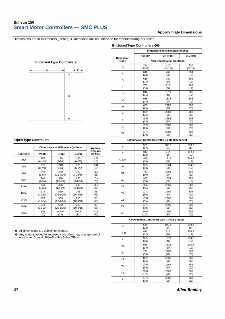
Bulletin 150Smart Motor Controllers — SMC PLUS
47
Approximate Dimensions
Dimensions are in millimeters (inches). Dimensions are not intended for manufacturing purposes
Enclosed Type Controllers ➊➋
DimensionCode
Dimensions in Millimeters (Inches)
A Width B Height C Depth
Non-Combination Controller
Q 244(9-5/8)
410(16-1/8)
220(8-2/3)
R 610(24)
762(30)
254(10)
S 610(24)
762(30)
305(12)
T 762(30)
915(36)
305(12)
U 915(36)
1219(48)
305(12)
V 965(38)
1524(60)
305(12)
W 635(25)
2286(90)
508(20)
X 889(35)
2286(90)
508(20)
Y 1397(55)
2286(90)
508(20)
Z 1524(60)
2286(90)
508(20)
Z1 1778(70)
2286(90)
508(20)
Open Type Controllers Combination Controllers with Fusible Disconnect
Controller
Dimensions in Millimeters (Inches) Approx.Ship Wt.kg (lbs)
S 559(22)
609.6(24)
203.2(8)
Width Height Depth T 813(32)
914(36)
304.8(12)
24A 155(6-1/16)
180(7-1/8)
160(6-1/4)
4.5(10) U & V 965
(38)1219(48)
304.8(12)
35A 215(8-7/16)
240(9-1/2)
170(6-5/8)
6.8(15) W 965
(38)1524(60)
304.8(12)
54A 245(9-5/8)
290(11-7/16)
200(7-13/16)
11.3(25) X1 762
(30)2286(90)
508(20)
97A 248(9-3/4)
336(13-1/4)
230(9-1/16)
10.4(23) X2 965
(38)1524(60)
356(14)
135A 248(9-3/4)
336(13-1/4)
230(9-1/16)
11.8(26) Y1 1143
(45)2286(90)
508(20)
180A 273(10-3/4)
560(22-1/16)
268(10-9/16)
25(55) Y2 1270
(50)2286(90)
508(20)
240A 273(10-3/4)
560(22-1/16)
268(10-9/16)
30(65) Z1 1397
(55)2286(90)
508(20)
360A 273(10-3/4)
560(22-1/16)
268(10-9/16)
30(65) Z2 1778
(70)2286(90)
508(20)
500A 508(20)
609.6(24)
304.8(12)
40.8(90) Z3 2667
(105)2286(90)
508(20)
Combination Controllers with Circuit Breaker
➊ All dimensions are subject to change.➋ Any options added to enclosed controllers may change size of
enclosure. Consult Allen-Bradley Sales Office.
S 559(22)
609.6(24)
203.2(8)
T & U 813(32)
914(36)
304.8(12)
V 965(38)
1219(48)
304.8(12)
W 965(38)
1524(60)
304.8(12)
X 762(30)
2286(90)
508(20)
Y1 889(35)
2286(90)
508(20)
Y2 1397(55)
2286(90)
508(20)
Y3 2667(105)
2286(90)
508(20)
Z 1778(70)
2286(90)
508(20)
A C
B
Enclosed Type Controllers

Bulletin 150Smart Motor Controllers — SMC Dialog Plus
48
0
Bulletin 150
• SMC Dialog PlusSmart Motor Controller• 24…1000A Ratings• 4 Standard Start
Modes• Options Include:
• Soft Stop• Pump Control• Preset Slow Speed• SMB Smart Motor
Braking• Accu-Stop• Slow Speed with
Braking
TABLE OF CONTENTSDescription Page Description PageFeatures. . . . . . . . . . . . . . . . . . . . . . . . . . . . . . . . . . . . . . . . . . . . . 48Starting and Stopping Options . . . . . . . . . . . . . . . . . . . . . . . . . . 49Modes of Operation . . . . . . . . . . . . . . . . . . . . . . . . . . . . . . . . . . . 49Description of Starting and Stopping Options . . . . . . . . . . . . . 50Description of Features . . . . . . . . . . . . . . . . . . . . . . . . . . . . . . . . 52Catalog Number Identification. . . . . . . . . . . . . . . . . . . . . . . . . . . 54
Product Selection . . . . . . . . . . . . . . . . . . . . . . . . . . . . . . . . . . . . . 56Options. . . . . . . . . . . . . . . . . . . . . . . . . . . . . . . . . . . . . . . . . . . . . . 64Enclosed Options . . . . . . . . . . . . . . . . . . . . . . . . . . . . . . . . . . . . . 65Accessories . . . . . . . . . . . . . . . . . . . . . . . . . . . . . . . . . . . . . . . . . . 67Specifications . . . . . . . . . . . . . . . . . . . . . . . . . . . . . . . . . . . . . . . . 70Approximate Dimensions and Shipping Weights. . . . . . . . . . . . 74
DescriptionThe SMC Dialog Plus controller provides microprocessor controlled starting forstandard three-phase squirrel cage induction motors. Four standard modes of operation are available within a single controller:
Optional SMC Easy Ship Program• Non-Combination Controllers — Cat.
Nos. printed in blue will ship in two working days.
• Combination Controllers — Cat. Nos.printed in blue will ship in four workingdays.
• Contact your distributor for availability
• Orders for multiple quantities mayincrease lead time.
• Soft Start with Selectable Kickstart• Current Limit Start• Dual Ramp Start• Full Voltage StartFeatures• Motor Protection• Metering• SCANport Communication
• LCD Display• Keypad Programming• Three Programmable Auxiliary Contacts
The SMC Dialog Plus controller is available for motors rated 1A through 1000A;200 through 480V AC, or 200 through 600V AC, 50 and 60 Hz. In addition tomotors, the SMC Dialog Plus controller can be used to control resistive loads.
SMC Dialog Plus, SMB, and Accu-Stop are trademarks of Allen-BradleyCompany, Inc.
Your order must include:• Cat. No. of the controller selected.
• Options (if required).
• Accessories (if required).
DeviceNet is a trademark of the Open Device Vendors Association (O.D.V.A.).

Bulletin 150Smart Motor Controllers — SMC Dialog Plus
49
Modes of Operation
Starting and Stopping Options
The following options are available in the SMC Dialog Plus controller:• Soft Stop• Pump Control• Preset Slow Speed• SMB Smart Motor Braking• Accu-Stop• Slow Speed with Braking
Modes of OperationThe SMC Dialog Plus controller provides the following modes of operation: Soft Start with selectable Kickstart, Current Limit Start, Dual Ramp Start, and Full Voltage Start.
Soft Start
This method has the most general application. The motor is raised to an initial torque value which is programmable from 0 to 90% of locked rotor torque. The motor voltage is gradually increased during the acceleration ramp time, which can be programmed from 0 to 30 seconds.
Soft Start with Selectable Kickstart
A kickstart, or boost, at the beginning of the voltage ramp is intended to provide a current pulse of 550% of full load current. The kickstart time is adjustable from 0.0 to 2.0 seconds. This allows the motor to develop additional torque at start for loads which may need a boost to get started.
Current Limit Start
This starting mode is used when it is necessary to limit the maximum starting current. The current limit can be programmed for 50 to 600% of full load current.
Dual Ramp Start
This starting mode is useful on applications that have varying loads and therefore varying starting torque requirements. The Dual Ramp Start offers the user the option to select between two separate Soft Start profiles with separately adjustable ramp times and initial torque settings.
The acceleration ramp times can be programmed from 0 to 30 seconds. The initial torque values can be programmed from 0 to 90% of locked rotor torque.
Note: Dual Ramp is only available with the standard controller.
100%
InitialTorque
PercentVoltage
Start Run
Time (seconds)
100
InitialTorque
PercentVoltage
Start Run
Time (seconds)
Kickstart(when selected)
500%
50%
StartTime (seconds)
PercentFull
LoadCurrent
PercentVoltage
InitialTorque
100%
Start #1
Ramp #2
Ramp #1
RunRun RunStart #2
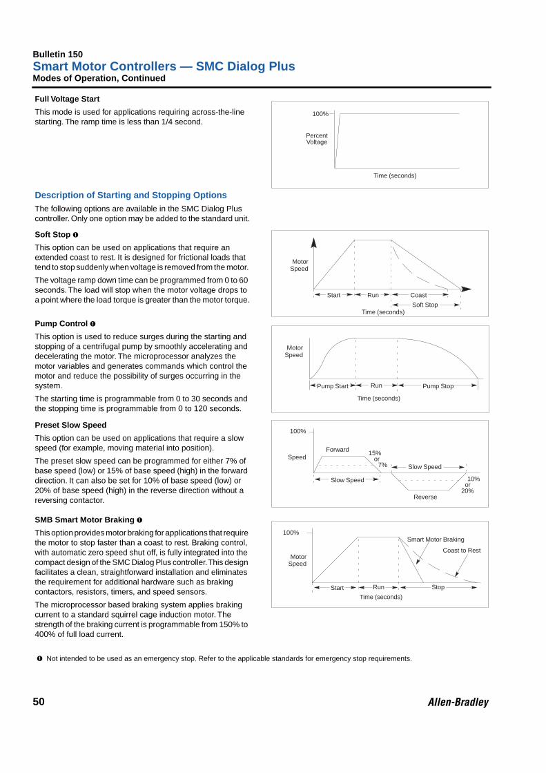
Bulletin 150Smart Motor Controllers — SMC Dialog Plus
50
Modes of Operation, Continued
Full Voltage StartThis mode is used for applications requiring across-the-line starting. The ramp time is less than 1/4 second.
Description of Starting and Stopping Options The following options are available in the SMC Dialog Plus controller. Only one option may be added to the standard unit.
Soft Stop
➊
This option can be used on applications that require an extended coast to rest. It is designed for frictional loads that tend to stop suddenly when voltage is removed from the motor. The voltage ramp down time can be programmed from 0 to 60 seconds. The load will stop when the motor voltage drops to a point where the load torque is greater than the motor torque.
Pump Control
➊
This option is used to reduce surges during the starting and stopping of a centrifugal pump by smoothly accelerating and decelerating the motor. The microprocessor analyzes the motor variables and generates commands which control the motor and reduce the possibility of surges occurring in the system.The starting time is programmable from 0 to 30 seconds and the stopping time is programmable from 0 to 120 seconds.
Preset Slow SpeedThis option can be used on applications that require a slow speed (for example, moving material into position). The preset slow speed can be programmed for either 7% of base speed (low) or 15% of base speed (high) in the forward direction. It can also be set for 10% of base speed (low) or 20% of base speed (high) in the reverse direction without a reversing contactor.
SMB Smart Motor Braking
➊
This option provides motor braking for applications that require the motor to stop faster than a coast to rest. Braking control, with automatic zero speed shut off, is fully integrated into the compact design of the SMC Dialog Plus controller. This design facilitates a clean, straightforward installation and eliminates the requirement for additional hardware such as braking contactors, resistors, timers, and speed sensors. The microprocessor based braking system applies braking current to a standard squirrel cage induction motor. The strength of the braking current is programmable from 150% to 400% of full load current.
➊ Not intended to be used as an emergency stop. Refer to the applicable standards for emergency stop requirements.
100%
PercentVoltage
Time (seconds)
Motor
Start Run
Time (seconds)Soft Stop
Coast
Speed
Pump StopPump Start
Motor
Run
Speed
Time (seconds)
Slow Speed
Speed
100%
Slow Speed
Forward
Reverse
10%or
20%
15%or
7%
Motor
Start RunTime (seconds)
Stop
Speed
100%
Coast to Rest
Smart Motor Braking

Bulletin 150Smart Motor Controllers — SMC Dialog Plus
51
Description of Options, Continued
Accu-Stop
➊
This option is used in applications requiring controlled position stopping. During stopping, braking torque is applied to the motor until it reaches preset slow speed (7 or 15% of rated speed) and holds the motor at this speed until a stop command is given. Braking torque is then applied until the motor reaches zero speed.
Braking current is programmable from 0 to 400% of full load current. Slow Speed Current is programmable from 0 to 450% of full load current. Slow speed can be programmed for either 7% (low) or 15% (high).
Accu-Stop with Slow Speed at Start
➊
The Accu-Stop option can also allow the motor to operate at a preset slow speed when Slow Speed Start is selected. This minimizes the jogging required to position a load. The start command will ramp the voltage from the preset slow speed to full speed. The operation of Accu-Stop is the same as explained previously.
Slow Speed with Braking
➊
Slow Speed with Braking is used on applications that require slow speed (in the forward direction) for positioning or alignment and also require braking control to stop.
Slow speed adjustments are 7% (low) or 15% (high) of rated speed. Slow speed acceleration current is adjustable from 0 to 450%. Slow speed running current is adjustable from 0 to 450% of full load current. Braking current is adjustable from 0 to 400%.
➊ Not intended to be used as an emergency stop. Refer to the applicable standards for emergency stop requirements.
Stop
Motor
Start RunTime (seconds)
Accu
Speed
100%
CoastBraking
Braking
Slow Speed
AccuStop
Run
Speed
Motor
Start
Speed
100% Braking
Slow SpeedSlow Speed
Slow
Start
Braking /Coast
Time (seconds)
StopRunSlowSpeed
Start
Speed
100%
Braking
Coast toRest
15%or
7%
Time (seconds)

Bulletin 150Smart Motor Controllers — SMC Dialog Plus
52
Description of Features
Electronic Motor Overload ProtectionThe SMC Dialog Plus controller incorporates, as standard, electronic motor overload protection. This overload protection is accomplished electronically with an I2t algorithm.When coordinated with the proper short circuit protection, overload protection is intended to protect the motor, motor controller, and power wiring against overheating caused by excessive overcurrent. The SMC Dialog Plus controller meets applicable requirements as a motor overload protective device.The controller’s overload protection is programmable, providing the user with flexibility. The overload trip class can be selected for class 10, 15, 20 or 30 protection. The trip current is programmed by entering the motor full load current rating.Thermal memory is included to accurately model motor operating temperature. Ambient insensitivity is inherent in the electronic design of the overload.Note: The current sensing capability of the SMC Dialog Plus controller is disabled during bypass operation. The Bulletin 825 Converter Module is required for providing current feedback in these applications. Note: To achieve calibration, 70% motor load or greater is required at the motor shaft for 2 seconds. Calibration is required when a Bulletin 825 Converter Module is not used.
Stall Protection and Jam DetectionMotors can experience locked rotor currents and develop high torque levels in the event of a stall or a jam. These conditions can result in winding insulation breakdown or mechanical damage to the connected load.The SMC Dialog Plus controller provides both stall protection and jam detection for enhanced motor and system protection. Stall protection allows the user to program a maximum stall protection delay time from 0 to 10 seconds. The stall protection delay time is in addition to the programmed start time and begins only after the start time has timed out. If the controller senses that the motor is stalled, it will shut down after the delay period has expired.Jam detection allows the user to determine the motor jam detection level as a percentage of the motor’s full load current rating. To prevent nuisance tripping, a jam detection delay time, from 0.0 to 10.0 seconds, can be programmed. This allows the user to select the time delay required before the SMC Dialog Plus controller will trip on a motor jam condition. The motor current must remain above the jam detection level during the delay time. Jam detection is active only after the motor has reached full speed.
Energy SaverThis is a standard feature with the SMC Dialog Plus controller. It is used to save energy on applications where the motor is lightly loaded or unloaded for long periods of time. The Energy Saver is a built-in feature of the controller. It does not require additional panel space or external wiring. And, it does not require a complicated setup procedure.
Phase RebalanceThe SMC Dialog Plus controller incorporates, as standard, a dynamic Phase Rebalance feature. The controller
compensates for voltage unbalance by automatically adjusting the voltage output to balance the three-phase currents drawn by the motor. When phase rebalance is achieved, motor life may be extended and production can continue without interruption. Phase Rebalance is a built-in feature of the controller and does not require a complicated set-up procedure.Note: Phase Rebalance requires the use of the Bulletin 825 Converter Module and the 150-NFS fanning strip.Note: The performance of the Phase Rebalance feature is dependent on the motor’s loading and characteristics. Severe imbalances cannot be corrected.
Underload ProtectionUtilizing the underload protection of the SMC Dialog Plus controller, motor operation can be halted if a drop in current is sensed.The SMC Dialog Plus controller provides an adjustable underload trip setting from 0 to 99% of the programmed motor full load current rating with an adjustable trip delay time of 0 to 99 seconds.
Undervoltage ProtectionThe SMC Dialog Plus controller’s undervoltage protection will halt motor operation if a drop in the incoming line voltage is detected.The undervoltage trip level is adjustable as a percentage of the programmed line voltage, from 0 to 99%. To eliminate nuisance trips, a programmable undervoltage trip delay time of 0 to 99 seconds can also be programmed. The line voltage must remain below the undervoltage trip level during the programmed delay time.
Overvoltage ProtectionIf a rise in the incoming line voltage is detected, the SMC Dialog Plus controller’s overvoltage protection will halt motor operation.The overvoltage trip level is adjustable as a percentage of the programmed line voltage, from 0 to 99%. To eliminate nuisance trips, a programmable overvoltage trip delay time of 0 to 99 seconds can also be programmed. The line voltage must remain above the overvoltage trip level during the programmed delay time.
Voltage Unbalance ProtectionVoltage unbalance is detected by monitoring the three-phase supply voltage magnitudes in conjunction with the rotational relationship of the three phases. The controller will halt motor operation when the calculated voltage unbalance reaches the user-programmed trip level.The voltage unbalance trip level is programmable from 0 to 25% unbalance.
Excessive Starts Per HourThe SMC Dialog Plus controller allows the user to program the allowed number of starts per hour (up to 99). This helps eliminate motor stress caused by repeated starting during a short time period.

Bulletin 150Smart Motor Controllers — SMC Dialog Plus
53
Description of Features, Continued
MeteringPower monitoring parameters include:
• Three-phase current
• Three-phase voltage
• Power in kW
• Power usage in kWH
• Power factor
• Motor thermal capacity usage
• Elapsed time
Note: The motor thermal capacity usage allows the user to monitor the amount of overload thermal capacity usage before the SMC Dialog Plus controller’s built-in electronic overload trips.Note: In bypass configurations, the current sensing and power factor measurement capability of the SMC Dialog Plus controller is disabled. Three-phase current measurement, kW, kWH, and motor thermal capacity usage can still be maintained with the use of the Bulletin 825 Converter Module.Note: The usage of an SMC Controller on a generator and line power requires the use of a Bulletin 825 Converter Module.
Built-in SCANport CommunicationA serial interface port is provided as standard, which allows connection to a Bulletin 1201 Human Interface Module or a variety of Bulletin 1203 Communication Modules. This includes Allen-Bradley Remote I/O, DeviceNet network andRS 232/422/485-DF1.
LCD DisplayThe SMC Dialog Plus controller’s two-line 16-character backlit LCD display provides parameter identification using clear, informative text. Controller set up can be performed quickly and easily without the use of a reference manual. Parameters are arranged in an organized four-level menu structure for ease of programming and fast access to parameters.
Keypad ProgrammingProgramming of parameters is accomplished through a five-button keypad on the front of the SMC Dialog Plus controller. The five buttons include up and down arrows, an Enter button, a Select button, and an Escape button. The user needs only to enter the correct sequence of keystrokes for programming the SMC Dialog Plus controller.
Auxiliary ContactsThree hard contacts are furnished as standard with the SMC Dialog Plus controller. The first two contacts are programmable for Normal/Up-to-speed. The third is programmable for Normal/Fault.
Easy Ship ProgramSelect enclosed controllers are available with the following optional quick deliveries:• Type 1 and Type 12 non-combination controllers rated 97
to 360 Amp, 208 to 480V AC, ship in 48 hours.• Type 12 circuit breaker combination controllers rated 75 to
300 HP at 480V ship in 4 working days.Cat. Nos. listed in blue type are available on the Easy Ship Program. Orders for multiple quantities may increase lead time. Consult your Allen-Bradley distributor for details.

Bulletin 150Smart Motor Controllers — SMC Dialog Plus
54
Catalog Number Identification
Open and Non-Combination
Controller RatingsB24 24 amperes, 1…15 HP @ 480V ACB35 35 amperes, 1…25 HP @ 480V ACB54 54 amperes, 1…40 HP @ 480V ACB97 97 amperes, 5…75 HP @ 480V ACB135 135 amperes, 5…100 HP @ 480V ACB180 180 amperes, 5…150 HP @ 480V ACB240 240 amperes, 5… 200 HP @ 480V ACB360 360 amperes, 5…300 HP @ 480V ACB500 500 amperes, 4…400 HP @ 480V ACB650 650 amperes, 5…500 HP @ 480V ACB720 720 amperes, 5…600 HP @ 480V ACB850 850 amperes, 10… 700 HP @ 480V ACB1000 1000 amperes, 10…800 HP @ 480V AC
Input Line VoltageOpen TypeB 200…480V AC, 3 phase, 50 and 60 HzC 200…600V AC, 3 phase, 50 and 60 HzNon-Combination Enclosed OnlyH 200…208V AC, 3-phase, 50 and 60 HzA 230V AC, 3 phase, 50 and 60 HzB 200…480V AC, 3 phase, 50 and 60 HzC 200…600V AC, 3 phase, 50 and 60 Hz
Bulletin Number150 Solid-State Controller
Enclosure TypeN OpenA IP30 (Type 1)J IP54 (Type 12)F IP65 (Type 4)
Options (Select Only One)A Soft StopB Pump ControlC Preset Slow SpeedD SMB Smart Motor BrakingE Accu-StopF Slow Speed with Braking
Control VoltageD 100…240V ACR 24V AC/DC
Options8L Line Mounted Protective Module8M Load Mounted Protective Module8B Line and Load Mounted Protective Modules
150 B180 N B D A 8L– –

Bulletin 150Smart Motor Controllers — SMC Dialog Plus
55
Catalog Number Identification, Continued
Combination
Controller RatingsB24 24 amperes, 1…15 HP @ 480V ACB35 35 amperes, 1…25 HP @ 480V ACB54 54 amperes, 1…40 HP @ 480V ACB97 97 amperes, 5…75 HP @ 480V ACB135 135 amperes, 5…100 HP @ 480V ACB180 180 amperes, 5…150 HP @ 480V ACB240 240 amperes, 5…200 HP @ 480V ACB360 360 amperes, 5…300 HP @ 480V ACB500 500 amperes, 4…400 HP @ 480V ACB650 650 amperes, 5…500 HP @ 480V ACB720 720 amperes, 5…600 HP @ 480V ACB850 850 amperes, 10…700 HP @ 480V ACB1000 1000 amperes, 10…800 HP @ 480V AC
152H B240 A BD B 52 8B– –
Bulletin Number152B Solid-State Controller with Fusible
Disconnect and Isolating Contactor152H Solid-State Controller with Fusible
Disconnect153B Solid-State Controller with Circuit
Breaker and Isolating Contactor153H Solid-State Controller with Circuit
Breaker
Enclosure TypeA IP30 (Type 1)J IP54 (Type 12)F IP65 (Type 4)
Options8L Line Mounted Protective Module8M Load Mounted Protective Module8B Line and Load Mounted Protective Modules
Line VoltageHD 200…208V AC, 3 phase, 50 and 60 HzAD 230V AC, 3 phase, 50 and 60 HzBD 400…480V AC, 3 phase, 50 and 60 HzCD 500…600V AC, 3 phase, 50 and 60 Hz
Control OptionsA Soft StopB Pump ControlC Preset Slow SpeedD SMB Smart Motor BrakingE Accu-StopF Slow Speed with Braking
HorsepowerCat.No.
HPRating
Cat.No.
HPRating
Cat.No.
HPRating
Cat.No.
HPRating
Cat.No.
HPRating
39 5 44 25 49 75 56 250 61 50040 7.5 45 30 50 100 57 300 62 60041 10 46 40 51 125 58 350 63 70042 15 47 50 52 150 59 400 65 80043 20 48 60 54 200 60 450 67 1000
–

Bulletin 150Smart Motor Controllers — SMC Dialog Plus
56
0Product Selection
Open Type ControllersUp to 480V AC
Up to 600V AC
➊ Controllers rated 97A and greater are not equipped with line and load terminal lugs. See page 67 for terminal lug kits.
➋ The minimum rating is: 0.7kW for devices with current ratings of 54A or less; 4kW for devices rated 97A through 720A; 7.5kW for devices rated 850A and greater.
➌ HP ratings at motor terminal voltages for 208, 480 and 600 line volts respectively.
Current
➊Rating (A)
kW
➋ HP
➌PriceAdderCode
100 – 240V AC50/60 Hz ControlCat. No. Price
24V AC/DC ControlCat. No. Price
230V AC50 Hz
400V AC50 Hz
200V AC60 Hz
230V AC60 Hz
460V AC60 Hz
24 5.5 11 1…5 1…7.5 1…15 a 150-B24NBD $ 1788 150-B24NBR $ 178835 10 18.5 1…10 1…10 1…25 b 150-B35NBD 1874 150-B35NBR 187454 15 22 1…15 1…20 1…40 c 150-B54NBD 2160 150-B54NBR 216097 25 45 5…30 5…30 5…75 d 150-B97NBD 3483 150-B97NBR 3483135 37 75 5…40 5…50 5…100 e 150-B135NBD 5203 150-B135NBR 5203180 51 90 5…60 5…60 5…150 f 150-B180NBD 5775 150-B180NBR 5775240 75 132 5…75 5…75 5…200 g 150-B240NBD 6491 150-B240NBR 6491360 110 200 5…125 5…150 5…300 h 150-B360NBD 7065 150-B360NBR 7065500 150 257 5…150 5…200 5…400 i 150-B500NBD 10279 150-B500NBR 10279650 200 355 5…200 5…250 5…500 j 150-B650NBD 12714 150-B650NBR 12714720 220 400 5…250 5…300 5…600 k 150-B720NBD 13288 150-B720NBR 13288850 257 475 10…300 10…350 10…700 l 150-B850NBD 16583 150-B850NBR 165831000 315 530 10…350 10…400 10…800 m 150-B1000NBD 19590 150-B1000NBR 19590
Current
➊Rating (A)
kW
➋ HP
➌PriceAdderCode
100 – 240V AC50/60 Hz ControlCat. No. Price
24V AC/DC ControlCat. No. Price
230V AC 50 Hz
400V AC 50 Hz
500V AC 50 Hz
200V AC 60 Hz
230V AC 60 Hz
460V AC 60 Hz
575V AC 60 Hz
24 5.5 11 15 1…5 1…7.5 1…15 1…20 a 150-B24NCD $ 2120 150-B24NCR $ 2120
35 10 18.5 22 1…10 1…10 1…25 1…30 b 150-B35NCD 2223 150-B35NCR 2223
54 15 22 37 1…15 1…20 1…40 1…50 c 150-B54NCD 2566 150-B54NCR 2566
97 25 45 63 5…30 5…30 5…75 5…75 d 150-B97NCD 3970 150-B97NCR 3970
135 37 75 90 5…40 5…50 5…100 5…125 e 150-B135NCD 6205 150-B135NCR 6205
180 51 90 132 5…60 5…60 5…150 5…150 f 150-B180NCD 6893 150-B180NCR 6893
240 75 132 160 5…75 5…75 5…200 5…250 g 150-B240NCD 7753 150-B240NCR 7753
360 110 200 250 5…125 5…150 5…300 5…350 h 150-B360NCD 8440 150-B360NCR 8440
500 150 257 355 5…150 5…200 5…400 5…500 i 150-B500NCD 12284 150-B500NCR 12284
650 200 355 475 5…200 5…250 5…500 5…600 j 150-B650NCD 15150 150-B650NCR 15150
720 220 400 500 5…250 5…300 5…600 5…700 k 150-B720NCD 15866 150-B720NCR 15866
850 257 475 600 10…300 10…350 10…700 10…800 l 150-B850NCD 19878 150-B850NCR 19878
1000 315 530 710 10…350 10…400 10…800 10…1000 m 150-B1000NCD 23459 150-B1000NCR 23459
Options — Page 64Accessories — Page 67Specifications — Page 70Approximate Dimensions — Page 74
Discount Schedule W4

Bulletin 150Smart Motor Controllers — SMC Dialog Plus
57
Product Selection, Continued
IP30 (Type 1) Vented Enclosed Non-Combination Controllers
Requires a separate 100 to 240V, 50/60 Hz single-phase control source. Line and load terminations are provided as standard. Enclosures other than those listed are available; consult Allen-Bradley Sales Office.
➊ Includes internal circulating fan rather than enclosure ventilation.
➋ The minimum rating is 0.7kW for devices with current ratings of 54A or less; 4kW for devices rated 97A through 720A; 7.5kW for devices 850A and greater.
CurrentRating
(A)
HPPriceAdderCode Cat. No. Price
CurrentRating
(A)
kW
➋ HPPriceAdder Code Cat. No. Price
200V AC60 Hz
230V AC 50 Hz
230V AC 60 Hz
208V AC 240V AC24 1…5 a 150-B24AHD
➊ $ 2563 24 5.5 1…7.5 a 150-B24AAD
➊ $ 256335 1…10 b 150-B35AHD
➊ 2625 35 10 1…10 b 150-B35AAD
➊ 262554 1…15 c 150-B54AHD
➊ 2938 54 15 1…20 c 150-B54AAD
➊ 293897 5…30 d 150-B97AHD 5625 97 25 5…30 d 150-B97AAD 5625
135 5…40 e 150-B135AHD 7375 135 37 5…50 e 150-B135AAD 7375180 5…60 f 150-B180AHD 7875 180 51 5…60 f 150-B180AAD 7875240 5…75 g 150-B240AHD 9500 240 75 5…75 g 150-B240AAD 9500360 5…125 h 150-B360AHD 10625 360 110 5…150 h 150-B360AAD 10625500 5…150 i 150-B500AHD 14875 500 150 5…200 i 150-B500AAD 14875650 5…200 j 150-B650AHD 18500 650 200 5…250 j 150-B650AAD 18500720 5…250 k 150-B720AHD 19125 720 220 5…300 k 150-B720AAD 19125850 10…300 l 150-B850AHD 21125 850 257 10…350 l 150-B850AAD 211251000 10…350 m 150-B1000AHD 24000 1000 315 10…400 m 150-B1000AAD 24000
CurrentRating
(A)
kW
➋ HPPriceAdder Code Cat. No. Price
CurrentRating
(A)
kW
➋ HPPriceAdder Code Cat. No. Price
400V AC 50 Hz
460V AC 60 Hz
500V AC 50 Hz
575V AC 60 Hz
480V AC 600V AC24 11 1…15 a 150-B24ABD
➊ $ 2563 24 15 1…20 a 150-B24ACD
➊ $ 287535 18.5 1…25 b 150-B35ABD
➊ 2625 35 22 1…30 b 150-B35ACD
➊ 293854 22 1…40 c 150-B54ABD
➊ 2938 54 37 1…50 c 150-B54ACD
➊ 331397 45 5…75 d 150-B97ABD 5625 97 63 5…75 d 150-B97ACD 6125135 75 5…100 e 150-B135ABD 7375 135 90 5…125 e 150-B135ACD 8375180 90 5…150 f 150-B180ABD 7875 180 132 5…150 f 150-B180ACD 9125240 132 5…200 g 150-B240ABD 9500 240 160 5…250 g 150-B240ACD 10500360 200 5…300 h 150-B360ABD 10625 360 250 5…350 h 150-B360ACD 12000500 257 5…400 i 150-B500ABD 14875 500 355 5…500 i 150-B500ACD 16875650 355 5…500 j 150-B650ABD 18500 650 475 5…600 j 150-B650ACD 21000720 400 5…600 k 150-B720ABD 19125 720 500 5…700 k 150-B720ACD 21750850 475 10…700 l 150-B850ABD 21125 850 600 10…800 l 150-B850ACD 242501000 530 10…800 m 150-B1000ABD 24000 1000 710 10…1000 m 150-B1000ACD 27875
SMC Easy Ship program prices are printed in blue. See page 48.
Options — Page 64Accessories — Page 67Specifications — Page 70Approximate Dimensions — Page 74
Discount Schedule W4

Bulletin 150Smart Motor Controllers — SMC Dialog Plus
58
Product Selection, Continued
IP65 (Type 4) Enclosed Non-Combination ControllersRequire a separate 100 to 240V, 50/60 Hz single-phase control source. Line and load terminations are provided as standard. The 97 to 1000A controllers include a bypass contactor and a Bulletin 825 converter module. Enclosures other than those listed are available; consult Allen-Bradley Sales Office.
➊ Includes an internal circulating fan instead of a bypass contactor.➋ The minimum rating is 0.7kW for devices with current ratings of 54A or less; 4kW for devices rated 97A through 720A; 7.5kW for devices 850A
and greater.
CurrentRating
(A)
HPPriceAdder Code Cat. No. Price
CurrentRating
(A)
kW ➋ HPPriceAdder Code Cat. No. Price
200V AC60 Hz
230V AC 50 Hz
230V AC 60 Hz
208V AC 240V AC
24 1…5 a 150-B24FHD ➊$
2688 24 5.5 1…7.5 a 150-B24FAD ➊ $ 2688
35 1…10 b 150-B35FHD ➊ 2750 35 10 1…10 b 150-B35FAD ➊ 275054 1…15 c 150-B54FHD ➊ 3063 54 15 1…20 c 150-B54FAD ➊ 306397 5…30 d 150-B97FHD 5875 97 25 5…30 d 150-B97FAD 5875135 5…40 e 150-B135FHD 8063 135 37 5…50 e 150-B135FAD 8063180 5…60 f 150-B180FHD 8750 180 51 5…60 f 150-B180FAD 8750240 5…75 g 150-B240FHD 11250 240 75 5…75 g 150-B240FAD 11250360 5…125 h 150-B360FHD 13750 360 110 5…150 h 150-B360FAD 13750500 5…150 i 150-B500FHD 21250 500 150 5…200 i 150-B500FAD 21250650 5…200 j 150-B650FHD 29875 650 200 5…250 j 150-B650FAD 29875720 5…250 k 150-B720FHD 37375 720 220 5…300 k 150-B720FAD 37375850 10…300 l 150-B850FHD 42750 850 257 10…350 l 150-B850FAD 427501000 10…350 m 150-B1000FHD 48250 1000 315 10…400 m 150-B1000FAD 48250
CurrentRating
(A)
kW ➋ HPPriceAdder Code Cat. No. Price
CurrentRating
(A)
kW ➋ HPPriceAdder Code Cat. No. Price
400V AC50 Hz
460V AC 60 Hz
500V AC50 Hz
575V AC60 Hz
480V AC 600V AC24 11 1…15 a 150-B24FBD ➊ $ 2688 24 15 1…20 a 150-B24FCD ➊ $ 300035 18.5 1…25 b 150-B35FBD ➊ 2750 35 22 1…30 b 150-B35FCD ➊ 306354 22 1…40 c 150-B54FBD ➊ 3063 54 37 1…50 c 150-B54FCD ➊ 343897 45 5…75 d 150-B97FBD 5875 97 63 5…75 d 150-B97FCD 6438
135 75 5…100 e 150-B135FBD 8063 135 90 5…125 e 150-B135FCD 9063180 90 5…150 f 150-B180FBD 8750 180 132 5…150 f 150-B180FCD 9938240 132 5…200 g 150-B240FBD 11250 240 160 5…250 g 150-B240FCD 12313360 200 5…300 h 150-B360FBD 13750 360 250 5…350 h 150-B360FCD 25625500 257 5…400 i 150-B500FBD 21250 500 355 5…500 i 150-B500FCD 27438650 355 5…500 j 150-B650FBD 29875 650 475 5…600 j 150-B650FCD 32313720 400 5…600 k 150-B720FBD 37375 720 500 5…700 k 150-B720FCD 40000850 475 10…700 l 150-B850FBD 42750 850 600 10…800 l 150-B850FCD 459381000 530 10…800 m 150-B1000FBD 48250 1000 710 10…1000 m 150-B1000FCD 52188
Options — Page 64Accessories — Page 67Specifications — Page 70Approximate Dimensions — Page 74
Discount Schedule W4

Bulletin 150Smart Motor Controllers — SMC Dialog Plus
59
Product Selection, Continued
IP54 (Type 12) Enclosed Non-Combination Controllers
Require a separate 100 to 240V, 50/60 Hz single-phase control source. Line and load terminations are provided as standard. The 97 to 1000A controllers include a bypass contactor and a Bulletin 825 converter module. Enclosures other than those listed are available; consult Allen-Bradley Sales Office.
➊ Includes an internal circulating fan instead of a bypass contactor.➋ The minimum rating is 0.7kW for devices with current ratings of 54A or less; 4kW for devices rated 97A through 720A; 7.5kW for devices 850A
and greater.
CurrentRating
(A)
HPPriceAdder Code Cat. No. Price
CurrentRating
(A)
kW ➋ HPPriceAdder Code Cat. No. Price
200V AC60 Hz
230V AC 50 Hz
230V AC 60 Hz
208V AC 240V AC24 1…5 a 150-B24JHD ➊ $ 2563 24 5.5 1…7.5 a 150-B24JAD ➊ $ 256335 1…10 b 150-B35JHD ➊ 2625 35 10 1…10 b 150-B35JAD ➊ 262554 1…15 c 150-B54JHD ➊ 2938 54 15 1…20 c 150-B54JAD ➊ 293897 5…30 d 150-B97JHD 5875 97 25 5…30 d 150-B97JAD 5875
135 5…40 e 150-B135JHD 8063 135 37 5…50 e 150-B135JAD 8063180 5…60 f 150-B180JHD 8750 180 51 5…60 f 150-B180JAD 8750240 5…75 g 150-B240JHD 11250 240 75 5…75 g 150-B240JAD 11250360 5…125 h 150-B360JHD 13750 360 110 5…150 h 150-B360JAD 13750500 5…150 i 150-B500JHD 18625 500 150 5…200 i 150-B500JAD 18625650 5…200 j 150-B650JHD 26313 650 200 5…250 j 150-B650JAD 26313720 5…250 k 150-B720JHD 33188 720 220 5…300 k 150-B720JAD 33188850 10…300 l 150-B850JHD 39250 850 257 10…350 l 150-B850JAD 392501000 10…350 m 150-B1000JHD 44813 1000 315 10…400 m 150-B1000JAD 44813
CurrentRating
(A)
kW ➋ HPPriceAdder Code Cat. No. Price
CurrentRating
(A)
kW ➋ HPPriceAdder Code Cat. No. Price
400V AC 50 Hz
460V AC 60 Hz
500V AC 50 Hz
575V AC 60 Hz
480V AC 600V AC24 11 1…15 a 150-B24JBD ➊ $ 2563 24 15 1…20 a 150-B24JCD ➊ $ 287535 18.5 1…25 b 150-B35JBD ➊ 2625 35 22 1…30 b 150-B35JCD ➊ 293854 22 1…40 c 150-B54JBD ➊ 2938 54 37 1…50 c 150-B54JCD ➊ 331397 45 5…75 d 150-B97JBD 5875 97 63 5…75 d 150-B97JCD 6438
135 75 5…100 e 150-B135JBD 8063 135 90 5…125 e 150-B135JCD 9063180 90 5…150 f 150-B180JBD 8750 180 132 5…150 f 150-B180JCD 9938240 132 5…200 g 150-B240JBD 11250 240 160 5…250 g 150-B240JCD 12250360 200 5…300 h 150-B360JBD 13750 360 250 5…350 h 150-B360JCD 15063500 257 5…400 i 150-B500JBD 18625 500 355 5…500 i 150-B500JCD 20688650 355 5…500 j 150-B650JBD 26313 650 475 5…600 j 150-B650JCD 28813720 400 5…600 k 150-B720JBD 33188 720 500 5…700 k 150-B720JCD 35813850 475 10…700 l 150-B850JBD 39250 850 600 10…800 l 150-B850JCD 423751000 530 10…800 m 150-B1000JBD 44813 1000 710 10…1000 m 150-B1000JCD 48688
SMC Easy Ship program prices are printed in blue.See page 48.
Options — Page 64Accessories — Page 67Specifications — Page 70Approximate Dimensions — Page 74
Discount Schedule W4

Bulletin 150Smart Motor Controllers — SMC Dialog Plus
60
Product Selection, Continued
IP30 (Type 1) Vented Enclosed Combination Controllers with Fusible Disconnect ➊Includes a 120V control transformer and line and load terminations. Enclosures other than those listed are available; consult Allen-Bradley Sales Office.
➊ See page 73 for fuse clip sizing and type information.➋ The nominal current rating for the combination package may differ from the controller, based on the horsepower. Consult Allen-Bradley Sales
Office.➌ The Cat. Nos. listed are incomplete. Select the horsepower suffix from Table 1 to complete the Cat. No.. Example: To order a fusible disconnect
combination controller for a 200 HP motor with 480V line voltage, the Cat. No. is 152H-B240ABD-54.➍ Includes internal circulating fan rather than enclosure ventilation.
HPRange
Controller Current
Rating (A) ➋
PriceAdderCode Cat. No. ➌ Price
HPRange
Controller Current
Rating (A) ➋
PriceAdderCode Cat. No. ➌ Price
208V AC, 60 Hz 240V AC, 60 Hz1…5 24 a 152H-B24AHD-___ ➍ $ 5000 1…7-1/2 24 a 152H-B24AAD-___ ➍ $ 5000
7-1/2…10 35 b 152H-B35AHD-___ ➍ 5188 10 35 b 152H-B35AAD-___ ➍ 518815…20 54 c 152H-B54AHD-___ ➍ 6250 15…20 54 c 152H-B54AAD-___ ➍ 625025…30 97 d 152H-B97AHD-___ 9000 25…30 97 d 152H-B97AAD-___ 9000
40 135 e 152H-B135AHD-___ 10250 40…50 135 e 152H-B135AAD-___ 1037550…60 180 f 152H-B180AHD-___ 12750 60 180 f 152H-B180AAD-___ 12750
75 240 g 152H-B240AHD-___ 13625 75 240 g 152H-B240AAD-___ 13625100…125 360 h 152H-B360AHD-___ 16250 100…150 360 h 152H-B360AAD-___ 17500
150 500 i 152H-B500AHD-___ 21250 200 500 i 152H-B500AAD-___ 21625200 650 j 152H-B650AHD-___ 28500 250 650 j 152H-B650AAD-___ 28500250 720 k 152H-B720AHD-___ 30625 300 720 k 152H-B720AAD-___ 30625300 850 l 152H-B850AHD-___ 36250 350 850 l 152H-B850AAD-___ 36250350 1000 m 152H-B1000AHD-___ 39500 400 1000 m 152H-B1000AAD-___ 39500
HPRange
Controller Current
Rating (A) ➋
PriceAdderCode Cat. No. ➌ Price
HPRange
Controller Current
Rating (A) ➋
PriceAdderCode Cat. No. ➌ Price
480V AC, 60 Hz 600V AC, 60 Hz1…15 24 a 152H-B24ABD-___ ➍ $ 5000 1…20 24 a 152H-B24ACD-___ ➍ $ 5375
20…25 35 b 152H-B35ABD-___ ➍ 5188 25…30 35 b 152H-B35ACD-___ ➍ 562530…40 54 c 152H-B54ABD-___ ➍ 6125 40…50 54 c 152H-B54ACD-___ ➍ 675050…75 97 d 152H-B97ABD-___ 9000 60…75 97 d 152H-B97ACD-___ 9500
100 135 e 152H-B135ABD-___ 10250 100…125 135 e 152H-B135ACD-___ 11375125…150 180 f 152H-B180ABD-___ 12750 150 180 f 152H-B180ACD-___ 13875
200 240 g 152H-B240ABD-___ 13625 200…250 240 g 152H-B240ACD-___ 15250250…300 360 h 152H-B360ABD-___ 17500 300 360 h 152H-B360ACD-___ 17750350…400 500 i 152H-B500ABD-___ 22125 350…500 500 i 152H-B500ACD-___ 22125450…500 650 j 152H-B650ABD-___ 28500 600 650 j 152H-B650ACD-___ 30625
600 720 k 152H-B720ABD-___ 30625 700 7200 k 152H-B720ACD-___ 33125700 850 l 152H-B850ABD-___ 36250 800 850 l 152H-B850ACD-___ 39500800 1000 m 152H-B1000ABD-___ 39500 1000 1000 m 152H-B1000ACD-___ 43375
Table 1HP Suffix HP Suffix HP Suffix HP Suffix HP Suffix
1…5 -39 25 -44 75 -49 250 -56 500 -617.5 -40 30 -45 100 -50 300 -57 600 -6210 -41 40 -46 125 -51 350 -58 700 -6315 -42 50 -47 150 -52 400 -59 800 -6520 -43 60 -48 200 -54 450 -60 1000 -67
Options — Page 64Accessories — Page 67Specifications — Page 70Approximate Dimensions — Page 74
Discount Schedule W4

Bulletin 150Smart Motor Controllers — SMC Dialog Plus
61
Product Selection, Continued
IP54 (Type 12) Enclosed Combination Controllers with Fusible Disconnect ➊Include a 120V control transformer and line and load terminations. The 97 to 1000A controllers include a bypass contactor and aBulletin 825 converter module. Enclosures other than those listed are available; consult Allen-Bradley Sales Office.
➊ See page 73 for fuse clip sizing and type information.➋ The nominal current rating for the combination package may differ from the controller, based on the horsepower. Consult Allen-Bradley Sales
Office.➌ The Cat. Nos. listed are incomplete. Select the horsepower suffix from Table 1 to complete the Cat. No. Example: To order a fusible disconnect
combination controller for a 200 HP motor with 480V line voltage, the Cat. No. is 152H-B240JBD-54.➍ Supplied without bypass contactor or converter module.
HPRange
Controller Current
Rating (A) ➋
PriceAdderCode Cat. No. ➌ Price
HPRange
Controller Current
Rating (A) ➋
PriceAdderCode Cat. No. ➌ Price
208V AC, 60 Hz 240V AC, 60 Hz1…5 24 a 152H-B24JHD-___ ➍ $ 5250 1…7-1/2 24 a 152H-B24JAD-___ ➍ $ 5250
7-1/2…10 35 b 152H-B35JHD-___ ➍ 5750 10 35 b 152H-B35JAD-___ ➍ 575015…20 54 c 152H-B54JHD-___ ➍ 6875 15…20 54 c 152H-B54JAD-___ ➍ 687525…30 97 d 152H-B97JHD-___ 9500 25…30 97 d 152H-B97JAD-___ 9500
40 135 e 152H-B135JHD-___ 11000 40…50 135 e 152H-B135JAD-___ 1112550…60 180 f 152H-B180JHD-___ 12750 60 180 f 152H-B180JAD-___ 13500
75 240 g 152H-B240JHD-___ 14750 75 240 g 152H-B240JAD-___ 14750100…125 360 h 152H-B360JHD-___ 19000 100…150 360 h 152H-B360JAD-___ 19125
150 500 i 152H-B500JHD-___ 24625 200 500 i 152H-B500JAD-___ 24625200 650 j 152H-B650JHD-___ 35625 250 650 j 152H-B650JAD-___ 35625250 720 k 152H-B720JHD-___ 40625 300 720 k 152H-B720JAD-___ 40625300 850 l 152H-B850JHD-___ 46250 350 850 l 152H-B850JAD-___ 46250350 1000 m 152H-B1000JHD-___ 51000 400 1000 m 152H-B1000JAD-___ 51000
HPRange
Controller Current
Rating (A) ➋
PriceAdderCode Cat. No. ➌ Price
HPRange
Controller Current
Rating (A) ➋
PriceAdderCode Cat. No. ➌ Price
480V AC, 60 Hz 600V AC, 60 Hz1…15 24 a 152H-B24JBD-___ ➍ $ 5250 1…20 24 a 152H-B24JCD-___ ➍ $ 5875
20…25 35 b 152H-B35JBD-___ ➍ 5875 25…30 35 b 152H-B35JCD-___ ➍ 625030…40 54 c 152H-B54JBD-___ ➍ 6750 40…50 54 c 152H-B54JCD-___ ➍ 737550…75 97 d 152H-B97JBD-___ 9250 60…75 97 d 152H-B97JCD-___ 9750
100 135 e 152H-B135JBD-___ 11000 100…125 135 e 152H-B135JCD-___ 12188125…150 180 f 152H-B180JBD-___ 13375 150 180 f 152H-B180JCD-___ 14500
200 240 g 152H-B240JBD-___ 14750 200…250 240 g 152H-B240JCD-___ 15875250…300 360 h 152H-B360JBD-___ 19125 300 360 h 152H-B360JCD-___ 18500350…400 500 i 152H-B500JBD-___ 25125 350…500 500 i 152H-B500JCD-___ 24375450…500 650 j 152H-B650JBD-___ 35375 600 650 j 152H-B600JCD-___ 38125
600 720 k 152H-B720JBD-___ 40625 700 720 k 152H-B720JCD-___ 43250700 850 l 152H-B850JBD-___ 46250 800 850 l 152H-B850JCD-___ 49500800 1000 m 152H-B1000JBD-___ 51000 1000 1000 m 152H-B1000JCD-___ 54875
Table 1HP Suffix HP Suffix HP Suffix HP Suffix HP Suffix
1…5 -39 25 -44 75 -49 250 -56 500 -617.5 -40 30 -45 100 -50 300 -57 600 -6210 -41 40 -46 125 -51 350 -58 700 -6315 -42 50 -47 150 -52 400 -59 800 -6520 -43 60 -48 200 -54 450 -60 1000 -67
Options — Page 64Accessories — Page 67Specifications — Page 70Approximate Dimensions — Page 74
Discount Schedule W4

Bulletin 150Smart Motor Controllers — SMC Dialog Plus
62
Product Selection, Continued
IP30 (Type 1) Vented Enclosed Combination Controllers with Circuit Breaker ➊Includes a 120V control transformer and line and load terminations. Enclosures other than those listed are available; consult Allen-Bradley Sales Office.
➊ See page 73 for circuit breaker size and rating plug size.➋ The nominal current rating for the combination package may differ from the controller, based on the horsepower. Consult Allen-Bradley Sales
Office.➌ The Cat. Nos. listed are incomplete. Select the horsepower suffix from Table 1 to complete the Cat. No. Example: To order a circuit breaker style
combination controller for a 200 HP motor with 480V line voltage, the Cat. No. is 153H-B240ABD-54.➍ Includes internal circulating fan rather than enclosure ventilation.
HPRange
Controller Current
Rating (A) ➋
PriceAdderCode Cat. No. ➌ Price
HPRange
Controller Current
Rating (A) ➋
PriceAdderCode Cat. No. ➌ Price
208V AC, 60 Hz 240V AC, 60 Hz1…5 24 a 153H-B24AHD-___ ➍ $ 5507 1…7-1/2 24 a 153H-B24AAD-___ ➍ $ 5507
7-1/2…10 35 b 153H-B35AHD-___ ➍ 5638 10 35 b 153H-B35AAD-___ ➍ 563815…20 54 c 153H-B54AHD-___ ➍ 6950 15…20 54 c 153H-B54AAD-___ ➍ 695025…30 97 d 153H-B97AHD-___ 9310 25…30 97 d 153H-B97AAD-___ 9179
40 135 e 153H-B135AHD-___ 11146 40…50 135 e 153H-B135AAD-___ 1127750…60 180 f 153H-B180AHD-___ 12850 60 180 f 153H-B180AAD-___ 14030
75 240 g 153H-B240AHD-___ 14948 75 240 g 153H-B240AAD-___ 14948100…125 360 h 153H-B360AHD-___ 17702 100…150 360 h 153H-B360AAD-___ 18358
150 500 i 153H-B500AHD-___ 22947 200 500 i 153H-B500AAD-___ 22947200 650 j 153H-B650AHD-___ 28847 250 650 j 153H-B650AAD-___ 28847250 720 k 153H-B720AHD-___ 31339 300 720 k 153H-B720AAD-___ 31339300 850 l 153H-B850AHD-___ 37240 350 850 l 153H-B850AAD-___ 37240350 1000 m 153H-B1000AHD-___ 40387 400 1000 m 153H-B1000AAD-___ 40387
HP Range
Controller Current
Rating (A) ➋
PriceAdderCode Cat. No. ➌ Price HP Range
Controller Current
Rating (A) ➋
PriceAdderCode Cat. No. ➌ Price
480V AC, 60 Hz 600V AC, 60 Hz1…15 24 a 153H-B24ABD-___ ➍ $ 5507 1…20 24 a 153H-B24ACD-___ ➍ $ 5901
20…25 35 b 153H-B35ABD-___ ➍ 5638 25…30 35 b 153H-B35ACD-___ ➍ 695030…40 54 c 153H-B54ABD-___ ➍ 6819 40…50 54 c 153H-B54ACD-___ ➍ 747450…75 97 d 153H-B97ABD-___ 9179 60…75 97 d 153H-B97ACD-___ 9834
100 135 e 153H-B135ABD-___ 11146 100…125 135 e 153H-B135ACD-___ 12326125…150 180 f 153H-B180ABD-___ 14030 150 180 f 153H-B180ACD-___ 15210
200 240 g 153H-B240ABD-___ 14948 200…250 240 g 153H-B240ACD-___ 16522250…300 360 h 153H-B360ABD-___ 18358 300 360 h 153H-B360ACD-___ 19407350…400 500 i 153H-B500ABD-___ 22554 350…500 500 i 153H-B500ACD-___ 23603450…500 650 j 153H-B650ABD-___ 28585 600 650 j 153H-B650ACD-___ 31339
600 720 k 153H-B720ABD-___ 31339 700 720 k 153H-B720ACD-___ 34093700 850 l 153H-B850ABD-___ 37240 800 850 l 153H-B850ACD-___ 40649800 1000 m 153H-B1000ABD-___ 40387 1000 1000 m 153H-B1000ACD-___ 44451
Table 1HP Suffix HP Suffix HP Suffix HP Suffix HP Suffix
1…5 -39 25 -44 75 -49 250 -56 500 -617.5 -40 30 -45 100 -50 300 -57 600 -6210 -41 40 -46 125 -51 350 -58 700 -6315 -42 50 -47 150 -52 400 -59 800 -6520 -43 60 -48 200 -54 450 -60 1000 -67
Options — Page 64Accessories — Page 67Specifications — Page 70Approximate Dimensions — Page 74
Discount Schedule W4

Bulletin 150Smart Motor Controllers — SMC Dialog Plus
63
Product Selection, Continued
IP54 (Type 12) Enclosed Combination Controllers with Circuit Breaker ➊Includes a 120V control transformer and line and load terminations. The 97 to 1000A controllers include a bypass contactor and a Bulletin 825 converter module. Enclosures other than those listed are available; consult Allen-Bradley Sales Office.
➊ See page 73 for circuit breaker size and rating plug size.➋ The nominal current rating for the combination package may differ from the controller, based on the horsepower. Consult Allen-Bradley Sales
Office.➌ The Cat. Nos. listed are incomplete. Select the horsepower suffix from Table 1 to complete the Cat. No.. Example: To order a circuit breaker
style combination controller for a 200 HP motor with 240V line voltage, the Cat. No. is 153H-B240JAD-54.➍ Supplied without bypass contactor or converter module.
HP Range
Controller Current
Rating (A) ➋
PriceAdderCode Cat. No. ➌ Price HP Range
Controller Current
Rating (A) ➋
PriceAdderCode Cat. No. ➌ Price
208V AC, 60 Hz 240V AC, 60 Hz 1…5 24 a 153H-B24JHD-___ ➍ $ 5901 1…7-1/2 24 a 153H-B24JAD-___ ➍ $ 5901
7-1/2…10 35 b 153H-B35JHD-___ ➍ 6163 10 35 b 153H-B35JAD-___ ➍ 616315…20 54 c 153H-B54JHD-___ ➍ 7343 15…20 54 c 153H-B54JAD-___ ➍ 734325…30 97 d 153H-B97JHD-___ 9834 25…30 97 d 153H-B97JAD-___ 9834
40 135 e 153H-B135JHD-___ 11670 40…50 135 e 153H-B135JAD-___ 1180350…60 180 f 153H-B180JHD-___ 13375 60 180 f 153H-B180JAD-___ 14686
75 240 g 153H-B240JHD-___ 15735 75 240 g 153H-B240JAD-___ 15735100…125 360 h 153H-B360JHD-___ 18620 100…150 360 h 153H-B360JAD-___ 19275
150 500 i 153H-B500JHD-___ 25569 200 500 i 153H-B500JAD-___ 25569200 650 j 153H-B650JHD-___ 38420 250 650 j 153H-B650JAD-___ 38420250 720 k 153H-B720JHD-___ 43271 300 720 k 153H-B720JAD-___ 43271300 850 l 153H-B850JHD-___ 49303 350 850 l 153H-B850JAD-___ 49303350 1000 m 153H-B1000JHD-___ 52319 400 1000 m 153H-B1000JAD-___ 52319
HP Range
Controller Current
Rating (A) ➋
PriceAdderCode Cat. No. ➌ Price HP Range
Controller Current
Rating (A) ➋
PriceAdderCode Cat. No. ➌ Price
480V AC, 60 Hz 600V AC, 60 Hz1…15 24 a 153H-B24JBD-___ ➍ $ 5901 1…20 24 a 153H-B24JCD-___ ➍ $ 6294
20…25 35 b 153H-B35JBD-___ ➍ 6163 25…30 35 b 153H-B35JCD-___ ➍ 721230…40 54 c 153H-B54JBD-___ ➍ 7212 40…50 54 c 153H-B54JCD-___ ➍ 786750…75 97 d 153H-B97JBD-___ 9703 60…75 97 d 153H-B97JCD-___ 10228
100 135 e 153H-B135JBD-___ 11670 100…125 135 e 153H-B135JCD-___ 12850125…150 180 f 153H-B180JBD-___ 14555 150 180 f 153H-B150JCD-___ 15735
200 240 g 153H-B240JBD-___ 15735 200…250 240 g 153H-B240JCD-___ 17571250…300 360 h 153H-B360JBD-___ 19275 300 360 h 153H-B360JCD-___ 20324350…400 500 i 153H-B500JBD-___ 26881 350…500 500 i 153H-B500JCD-___ 26881450…500 650 j 153H-B650JBD-___ 37371 600 650 j 153H-B650JCD-___ 41042
600 720 k 153H-B720JBD-___ 43271 700 720 k 153H-B720JCD-___ 46156700 850 l 153H-B850JBD-___ 49303 800 850 l 153H-B850JCD-___ 52712800 1000 m 153H-B1000JBD-___ 52319 1000 1000 m 153H-B1000JCD-___ 56384
Table 1HP Suffix HP Suffix HP Suffix HP Suffix HP Suffix
1…5 -39 25 -44 75 -49 250 -56 500 -617.5 -40 30 -45 100 -50 300 -57 600 -6210 -41 40 -46 125 -51 350 -58 700 -6315 -42 50 -47 150 -52 400 -59 800 -6520 -43 60 -48 200 -54 450 -60 1000 -67
SMC Easy Ship program prices are printed in blue. See page 48.
Options — Page 64Accessories — Page 67Specifications — Page 70Approximate Dimensions — Page 74
3Discount Schedule W4

Bulletin 150Smart Motor Controllers — SMC Dialog Plus
64
Options
➊ Add the designated letter to the end of the Cat. No. For example, to add the Pump Control option: Cat. No. 150-B24NBDB or Cat. No. 152H-B180JBDB-51.
Option Description
PriceAdder Code
Cat. No. Modification
List PriceAdder
Soft Stop Provides a ramp down time of 0 to 60 seconds for applications which require an extended coast-to-rest. a…m A ➊ $ 173
Pump ControlProvides smooth motor acceleration and deceleration, reducing surges caused by the starting and stopping of centrifugal pumps. Starting time is adjustable from 0 to 30 seconds, and stopping time is adjustable from 0 to 120 seconds.
a…m B ➊ 1434
Preset Slow Speed
Provides preset slow speeds for positioning or alignment applications. Preset speeds can be selected at either 7% or 15% of rated motor speed, with adjustable slow speed current from 0% to 450% of full load motor current.
a…m C ➊ 215
SMB Smart Motor Braking
Provides a microprocessor based braking system that applies three-phase braking current to a standard squirrel cage induction motor. The strength of the braking cur-rent is adjustable from 0% to 400% of the motor’s full load current rating.
abcdefghijkl
m
D ➊
7451311152624713761419147295158752193499778
1224914505
Accu-Stop
Provides stopping control for general positioning or to minimize jogging to stop. A three-phase braking current is applied to the motor (adjustable from 0% to 400% of full load current) until it reaches a preset slow speed (either 7% or 15% of rated motor speed). The motor is held at this speed until a stop command is given. Brak-ing torque is then applied until the motor reaches zero speed. Slow speed current is adjustable from 0% to 450% of full load current.
abcdefghijkl
m
E ➊
9601526174126863976440649435373773695639993
1246414720
Slow Speed with Braking
Provides a preset slow speed for positioning or alignment applications. Preset speeds can be selected at either 7% or 15% of rated motor speed, with adjustable slow speed current from 0% to 450% of full load current.Provides a microprocessor based braking system that applies three-phase braking current to a standard squirrel cage induction motor. The strength of the braking cur-rent is adjustable from 0% to 400% of full load motor current.
abcdefghijkl
m
F ➊
9601526174126863976440649435373773695639993
1246414720
Protective Modules
24…54A, 480V Line Side Protective Module a…c
-8L
33097…360A, 480V Line Side Protective Module d…h 39524…54A, 600V Line Side Protective Module a…c 43097…360A, 600V Line Side Protective Module d…h 50324…54A, 480V Load Side Protective Module a…c
-8M
33097…360A, 480V Load Side Protective Module d…h 39524…54A, 600V Load Side Protective Module a…c 43097…360A, 600V Load Side Protective Module d…h 50324…54A, 480V Both Line and Load Side Protective Modules a…c
-8B
66097…360A, 480V Both Line and Load Side Protective Modules d…h 78924…54A, 600V Both Line and Load Side Protective Modules a…c 86097…360A, 600V Both Line and Load Side Protective Modules d…h 1004
SMC Easy Ship program prices are printed in blue. See page 48.
Product Selection — Page 56
Discount Schedule W4

Bulletin 150Smart Motor Controllers — SMC Dialog Plus
65
Enclosed Options
➊ Option pushbuttons are available only when the corresponding option module is selected. For example: Cat. No. 150-B24JBDA-1XA.➋ To order a combination enclosed controller with an isolation contactor, add the letter “B” to the bulletin prefix. For example, Cat. No.
152H-B135JBD-50 becomes Cat. No. 152B-B135JBD-50. Bulletin 100 contactors are used through 600A. Enclosure dimensions are subject to change. Consult Allen-Bradley Sales Office.
➌ Specify pilot light lens color. Options: Amber, Blue, Clear, Green, Red, and White. For example, -4R for a red lens.
Option Description
PriceAdder Code
Cat. No. Modification
List Price Adder
Push Buttons
Start-Stop Push Button a…m -1 $ 163Start-Stop Push Button with H-O-A Selector Switch a…m -1F 306Soft Stop Push Button ➊ a…m -1XA ➊ 81Pump Stop Push Button ➊ a…m -1XB ➊ 81Slow Speed Push Button ➊ a…m -1XC ➊ 81Brake Push Button ➊ a…m -1XD ➊ 81Accu-Stop/Slow Speed Push Button ➊ a…m -1XE ➊ 81
IsolationContactor Line-Side Contactor
a…de…f
ghij
k…lm
➋
375563813
20632625731390639688
Selector Switch Hand-Off-Auto Selector Switch a…m -3 144
Pilot LightsTransformer Pilot Lights (Red Lens — Easy Ship Program) a…m -4_ ➌ 106Push-to-Test Pilot Lights a…m -5_ ➌ 150
Control Circuit Transformer Control Circuit Transformer (fused primary and secondary) a…m -6P 250
SCR Fusing
Fast acting current limiting SCR fusing for 24A unit a
-SCR
688Fast acting current limiting SCR fusing for 35A unit b 700Fast acting current limiting SCR fusing for 54A unit c 813Fast acting current limiting SCR fusing for 97…135A units d…e 1188Fast acting current limiting SCR fusing for 180A unit f 1250Fast acting current limiting SCR fusing for 240A unit g 2125Fast acting current limiting SCR fusing for 360A unit h 3000Fast acting current limiting SCR fusing for 500A unit i 3750Fast acting current limiting SCR fusing for 650…720A units j…k 6875Fast acting current limiting SCR fusing for 850A unit l 7000Fast acting current limiting SCR fusing for 1000A unit m 13750
Door-MountedHuman Inter-face Module
Programmer Only (Type 1) a…m -HAP 310Programmer Only (Type 4/12) a…m -HJP 435Digital Control Panel (Type 1) a…m -HA2 340Digital Control Panel (Type 4/12) a…m -HJ2 470
CommunicationModule
Remote I/O a…m -GD1 625RS- 232/422/485 a…m -GD2 625DH485 a…m -GD2 625DeviceNet Network a…m -GK5 625
UnwiredControl Relays
Bulletin 700F 4-pole relay — 2 N.O. and 2 N.C. a…m -89F22 156Bulletin 700F 4-pole relay — 3 N.O. and 1 N.C. a…m -89F31 156Bulletin 700F 4-pole relay — 4 N.O. a…m -89F40 156
SMC Easy Ship program prices are printed in blue. See page 48.
Product Selection — Page 56
Discount Schedule W4

Bulletin 150Smart Motor Controllers — SMC Dialog Plus
66
Enclosed Options, Continued
Option Description
PriceAdder Code
Cat. No.Modification
List Price Adder
Auxiliary Contacts
N.O. auxiliary contacts for 24…240A units a…g-90
$ 75N.O. auxiliary contacts for 360…1000A units h…m 213N.C. auxiliary contacts for 24…240A units a…g
-9175
N.C. auxiliary contacts for 360…1000A units h…m 2131 N.O.…1 N.C. auxiliary contacts for 24…240A units
-9011 N.O.…1 N.C. auxiliary contacts for 360…1000A units
DisconnectAuxiliary
N.O. disconnect auxiliary mounted on operating mechanism(operates with movement of external handle only) a…m -98 113
N.C. disconnect auxiliary mounted on operating mechanism(operates with movement of external handle only) a…m -99 113
Circuit Breaker Auxiliary
Internal N.O. circuit breaker auxiliary a…m -98X 200Internal N.C. circuit breaker auxiliary a…m -99X 200
Shunt Trip Circuit Breaker Shunt Trip for 24…54A units a…c
-754
500Circuit Breaker Shunt Trip for 97…135A units d…e 875Circuit Breaker Shunt Trip for 180…240A units f…g 1000Circuit Breaker Shunt Trip for 360…500A units h…i 1250Circuit Breaker Shunt Trip for 650…850A units j…l 1875Circuit Breaker Shunt Trip for 1000A unit m 2250
Line Voltage Monitor
Bulletin 813S Line Voltage Monitor a…m -813S 638
Window Kit Standard (3 H x 5 W) (76.2mm H x 127mm W) a…m -WK1 500Hinged (10 H x 10 W) (254mm H x 254mm W) a…m -WK2 750
Product Selection — Page 56
Discount Schedule W4

Bulletin 150Smart Motor Controllers — SMC Dialog Plus
67
Accessories — Field Installed
Protective Modules ➊➋
Terminal Lug Kits (97A through 1000A)
IEC Terminal Covers
➊ The same protective module mounts on the line or load side of the SMC Dialog Plus Controller. For applications requiring both line and load side protection, two protective modules must be ordered.
➋ Surge protection is provided as standard on 500A through 1000A units.
Current Rating (A) Description
Price Adder Code
Field ModificationCat. No. Price
24…54
480V Protective Module
a…c
150-N84 $ 115
600V Protective Module 150-N86 215
97…360
480V Protective Module
d…h
150-N84L 144
600V Protective Module 150-N86L 244
CurrentRating (A)
ConductorRange
Total No. ofTerminal Lugs
Possible Each SidePkg.Qty. Cat. No. PriceLine Side Load Side
97…135 #6-4/0 AWG 3 3 3 199-LF1 $ 68
180…360 #6-4/0 AWG 6 6 3 199-LF1 68
500 #4-500MCM AWG 6 6 3 199-LG1 90
650…720 #4-500MCM AWG 9 9 3 199-LG1 90
850…1000 (2) 1/0-500MCM AWG 6 6 3 199-LJ1 255
DescriptionField Modification
Cat. No. PriceIEC line or load terminal covers for 97…135Adevices (includes line and load termination covers)
150-NT1 $ 144
IEC line and load terminal covers for 180…360Adevices (includes line and load termination covers)
150-NT2 215
Product Selection — Page 56
Discount Schedule W4

Bulletin 150Smart Motor Controllers — SMC Dialog Plus
68
Accessories — Field Installed, Continued
➊ Requires Type 1 Door Mount Bezel Kit.➋ Start, Stop and Jog buttons are the only active controls when used with the SMC Dialog Plus Controller.➌ Separately powered 120/240V AC.➍ Requires the use of a 1203-GD2 communication module.➎ Consult Allen-Bradley Sales Office.➏ Each Flex I/O SCANport Module requires (1) 1203-FB1 and (1) 1203-FM1.➐ Requires a Communication Option Cable (1202-C03/C10/C30/C90) to be functional. These units are not acceptable for NEMA Type 4 door
mounting or UL Type 4X outdoor only.➑ Use Discount Schedule 20.
Description Cat. No. Price
Human InterfaceModules
Door Mount Bezel Kit IP30 (Type 1) 1201-DMA $ 40
Programmer Only
IP30 (Type 1) ➊ 1201-HAP 220
IP65 (Type 4/12)with Bezel 1201-HJP 345
Analog Control Panel ➋ IP30 (Type 1) ➊ 1201-HA1 240
Digital Control Panel ➋
IP30 (Type 1) ➊ 1201-HA2 240
IP65 (Type 4/12)with Bezel 1201-HJ2 380
Description Use WithIP30 (Type 1)
Cat. No. Price
Communication Cables Male-Male
1/3 Meter
Human Interface Module and
Communications Modules
1202-C03 $ 50
1 Meter 1202-C10 65
3 Meters 1202-C30 95
9 Meters 1202-C90 140
Communication Modules
Single Point Remote I/O ➌
Bulletin 150SMC Dialog Plus
1203-GD1 420
RS232/RS422/RS485/DF1 ➌ 1203-GD2 420
DH485 ➌ 1203-GD2 420
DeviceNet Network 1203-GK5 420
DriveTools Programming Software ➍ Personal Computer 1300-DTLS ➎
Flex I/O SCANport Module ➏Flex I/O Terminal Base
Flex I/O Module Bulletin 150SMC Dialog Plus
1203-FB1 ➏1203-FM1 ➏➐
170 ➑295 ➑
SLC Communication Module 1203-SM1 1195
Cat. No. 1201-HA2
Cat. No. 1201-HA1
Cat. No. 1201-HAP
Communication CableCat. No. 1202-C10
Communication ModuleCat. No. 1203-GD1
Communication Option KitsCat. No. 1203-FM1 Cat No. 1203-SM1
Product Selection — Page 56
Discount Schedule O7

Bulletin 150Smart Motor Controllers — SMC Dialog Plus
69
Accessories — Field Installed, Continued
Converter Modules ➊
➊ Must be used with fanning strip Cat. No. 150-NFS.➋ Use Discount Schedule O7.
DescriptionMotor Full Load
Current Range (A) Cat. No. Price
1…12.5 825-MCM20 $ 445
9…100 825-MCM180 445
64…360 825-MCM630 445
Description Cat. No. PriceFanning Strip for Bulletin 825 Converter Modules
150-NFS $ 31 ➋
Optional Bus Bars for Cat. No. 825-MCM180FeaturesTerminals: M81/8 x 5/8 x 4-1/64 in. (4 x 16 x 102mm)Weight: 230g 825-MVM 65
Cat. No. 825-MCM180
Cat. No. 825-MCM630
Cat. No. 150-NFS
Product Selection — Page 56
Discount Schedule A1

Bulletin 150Smart Motor Controllers — SMC Dialog Plus
70
Specifications
Functional Design SpecificationsStandard Features Installation
Power WiringThe SMC Dialog Plus Controller can be wired with or without an isolation contactor. Bypass contactors can be employed after the controller has brought the motor to full speed.
Control Wiring 2- and 3-wire control for a wide variety of applications.Set-up Keypad The SMC Dialog Plus Controller is configured with the front keypad and backlit LCD
display.
Software Parameter values can be downloaded to the SMC Dialog Plus Controller with DriveTools programming software and the 1203-GD2 communication module.
Communications One serial port provided for connection to optional human interface and communication modules.
Starting Modes Soft start with selectable kickstart, current limit, dual ramp and full voltage in one unit.Protection and Diagnostics Power loss, line fault, voltage unbalance, excessive starts/hour, phase reversal,
undervoltage, overvoltage, controller temp, stall, jam, open gate, overload, underload, communication fault.
Metering Amps, volts, kW, kWH, elapsed time, power factor, motor thermal capacity usage.Status Indication Stopped, ramping, stopping, at speed and fault.Auxiliary Contacts (1) single-pole double-throw contact programmable as normal or up-to-speed; one
programmable as normal or fault.Optional Features Soft Stop Extended coast-to-rest to minimize load shifting. Ramp down time is adjustable from
0 to 60 seconds.Pump Control Helps reduce fluid surges in centrifugal pumping systems during starting and stopping
period. Starting time is adjustable from 0 to 30 seconds. Stopping time is adjustable from 0 to 120 seconds.
Preset Slow Speed Enables the operator to position material. The preset slow speed can be set for low (7% of base speed), high (15% of base speed), reverse low (10% of base speed) or reverse high (20% of base speed).
SMB Smart Motor Braking Provides motor braking without additional equipment for applications that require the motor to stop quickly. Braking current is adjustable from 0% to 400% of the motor’s full load current rating.
Accu-Stop/Slow Speed with Braking
Combines Smart Motor Braking and Preset Slow Speed. Braking current is adjustable from 0% to 400% of full load current. Slow speed can be set for either Low (7% of base speed) or High (15% of base speed).
Product Selection — Page 56

Bulletin 150Smart Motor Controllers — SMC Dialog Plus
71
Specifications, Continued
➊ For devices rated 24 through 500A, heatsink fans can be powered by either 110/120V AC or 220/240V AC. For devices rated 650 through 1000A, heatsink fans can only be powered by 110/120V AC.
Electrical Ratings UL/CSA/NEMA IECPower Circuit: Rated Operation Voltage 200…480V AC
200…600V AC (–15%, +10%)200…415V ~200…500V ~
Rated Insulation Voltage N/A 500V ~Rated Impulse Voltage N/A 6000VDielectric Withstand 2200V AC 2500V ~Repetitive Peak Inverse Voltage Rating
200…480V AC: 1400V200…600V AC: 1600V
200…415V ~: 1400V200…500V ~: 1600V
Operating Frequency 50/60 Hz 50/60 HzUtilization Category MG 1 AC-53aProtection Against Electrical Shock N/A IP00 (open device)DV/DT Protection RC Snubber NetworkTransient Protection Metal Oxide Varistors:
220 Joules @ 24…360A220 Joules @ 480V, 500…1000A300 Joules @ 600V, 500…1000A
Short Circuit Protection: SCPD Performance Type 1SCPD List Maximum Fuse or Circuit Breaker (A):Device Operational Current Rating (A):
24355497
135180240360500650720850
1000
80125200350500600700
100012001600200025003000
Control Circuit: Rated Operational Voltage 100…240V AC24V AC24V DC
100…240V ~24V ~
24V DCRated Insulation Voltage N/A 240V ~Rated Impulse Voltage N/A 3000VDielectric Withstand 1600V AC 2000V ~Operating Frequency 50/60 Hz 50/60 HzProtection Against Electric Shock N/A IP20
Power Requirements: Control Module 40 VAHeatsink Fan(s) (A) ➊
24355497
135180240360500650720850
1000
–––
45 VA45 VA45 VA45 VA45 VA
145 VA320 VA320 VA320 VA320 VA
Product Selection — Page 56

Bulletin 150Smart Motor Controllers — SMC Dialog Plus
72
Specifications, Continued
Electrical Ratings, Continued UL/CSA/NEMA IECMaximum Heat Dissipation (Watts): Controller Rating (A):
24355497
135180240360500650720850
1000
110150200285490660935
117014002025225024002760
Auxiliary Contacts: Rated Operation Voltage 240V AC 240V ~Rated Insulation Voltage N/A 240V ~Dielectric Withstand 1600V AC 2000V ~Operating Frequency 50/60 Hz 50/60 HzUtilization Category B300 (terminals 18…19)
C300 (terminals 18…20)C300 (terminals 29…30)
AC-15
SCPD Performance Type 2SCPD List Class CC 8A @ 1000A Available Fault Current
EnvironmentalOperating Temperature Range 0 C…50 C (32 F…122 F) (open)
0 C…40 C (32 F…104 F) (enclosed)Storage and Transportation Temperature Range –20 C…+75 CAltitude 2000 metersHumidity 5%…95% (non-condensing)Pollution Degree 2MechanicalResistance to Vibration
OperationalNon-Operational
1.0 G Peak, 0.006 Inch Displacement2.5 G, 0.015 Inch Displacement
Resistance to ShockOperational
Non-Operational15 G30 G
Construction Power Poles: Thermoset Moldings: 24…135AHeatsink hockey puck thyristor: 180…1000A
Control Modules: Thermoset and Thermoplastic MoldingsMetal Parts: Anodized Aluminum, Plated Brass, Copper or
Painted SteelTerminals Power Terminals:
24…54A: 6.0mm hole with clamp screw97 & 135A: One 11.5mm (0.453) diameter hole each180…360A: One 10.5mm (0.413) diameter hole each500A: Two 13.5mm (0.531) diameter holes each650 & 720A: Three 13.1mm (0.515) diameter holes
each850 & 1000A: Six 13.1mm (0.515) diameter holes each
Power Terminal Markings:NEMA, CENELEC EN50 012
Control Terminals:M 3.5 x 0.6 Pozidriv screw with self-lifting clamp plate
Product Selection — Page 56

Bulletin 150Smart Motor Controllers — SMC Dialog Plus
73
Specifications, Continued
Fuse Clip Sizing and Type for Fusible Combination Controllers ➊➋
Circuit Breaker Sizes and Rating Plug Sizes
➊ Consult NEC Handbook for proper fuse sizing guidelines.➋ Optional fuse clip sizes and types are available upon request. Consult Allen-Bradley Sales Office.➌ For higher interrupting ratings, consult Allen-Bradley Sales Office.
OtherEMC Emission Levels
Conducted Radio Frequency EmissionsRadiated Emissions
Class AClass A
EMC Immunity LevelsElectrostatic Discharge
Radio Frequency Electromagnetic FieldFast Transient
Surge Transient
8kV Air DischargePer IEC 947-4-2Per IEC 947-4-2Per IEC 947-4-2
Overload CharacteristicsCurrent Range
Trip ClassesTrip Current Rating
Number of Poles
1.0…999.9 Amps10, 15, 20 & 30
120% of Motor FLC3
ApprovalsOpen Type Controllers CE Marked Per Low Voltage Directive 73/23/EEC, 93/68/EEC
CSA Certified (File No. LR1234)UL Listed (File No. E96956)
Horsepower@ 480V
Fuse ClipSize/Type
Fuse SizeRange (A)
Horsepower@ 480V
Fuse ClipSize/Type
Fuse SizeRange (A)
15 30A/Class J 0…30 200 400A/Class J 201…40020 60A/Class J 31…60 250 600A/Class J 401…60025 60A/Class J 31…60 300 600A/Class J 401…60030 60A/Class J 31…60 350 600A/Class J 401…60040 100A/Class J 61…100 400 1200A/Class L 601…160050 100A/Class J 61…100 450 1200A/Class L 601…160060 200A/Class J 101…200 500 1200A/Class L 601…160075 200A/Class J 101…200 600 1200A/Class L 601…1600100 200A/Class J 101…200 700 1200A/Class L 601…1600125 400A/Class J 201…400 800 1200A/Class L 601…1600150 400A/Class J 201…400
Horsepower@ 480V
Circuit Breaker Size (A)/Rating Plug Size (A)
Interrupting Ratingin Symmetrical Amps
@ 480V ➌Horsepower
@ 480VCircuit Breaker Size (A)/
Rating Plug Size (A)
Interrupting Ratingin Symmetrical Amps
@ 480V ➌
15 150/50 14,000 200 400/400 35,00020 150/50 14,000 250 600/500 35,00025 150/60 14,000 300 600/600 35,00030 150/70 14,000 350 600/600 35,00040 150/100 14,000 400 800/800 50,00050 150/125 14,000 450 1200/1000 50,00060 250/150 25,000 500 1200/1000 50,00075 250/175 25,000 600 1200/1200 50,000100 250/225 25,000 700 2000/1600 65,000125 250/250 25,000 800 2000/2000 65,000150 400/300 35,000
Product Selection — Page 56

Bulletin 150Smart Motor Controllers — SMC Dialog Plus
74
Approximate Dimensions and Shipping Weights
Open Type Controllers Dimensions are not intended for manufacturing purposes.
Enclosed Type Controllers
.
Controller Rating (A)Dimensions in Millimeters (Inches)
WeightHeight Width Depth
24 180(7.09)
154(6.06)
185(7.29)
4.5 kg(10 lbs.)
35 240(9.45)
214(8.43)
195(7.68)
6.8 kg (15 lbs.)
54 290(11.42)
244(9.61)
225(8.86)
11.3 kg (25 lbs.)
97 336(13.23)
248(9.77)
256(10.09)
10.4 kg (23 lbs.)
135 336(13.23)
248(9.77)
256(10.09)
11.8 kg (26 lbs)
180 560(22.06)
273(10.75)
294(11.58)
25 kg (55 lbs.)
240 560(22.06)
273(10.75)
294(11.58)
30 kg (65 lbs.)
360 560(22.06)
273(10.75)
294(11.58)
30 kg (65 lbs.)
500 588(23.17)
508(20.00)
311(12.23)
40.8 kg (90 lbs.)
650…1000 1524(60.0)
813(32.00)
402(15.83)
167.8 kg (370 lbs.)
Dimensions are in millimeters (inches). Dimensions are not intended for manufacturing purposes. All dimensions are subject to change.
Factory installed options may affect enclosure size requirements.
Exact dimensions can be obtained after order entry. Please consultAllen-Bradley Sales Office.
Controller Rating (A)
IP30 (Type 1) IP54 (Type 12) IP65 (Type 4)B Height A Width C Depth B Height A Width C Depth B Height A Width C Depth
Non-Combination Controller
24 610(24)
406(16)
229(9)
610(24)
406(16)
229(9)
610(24)
406(16)
229(9)
35 762(30)
610(24)
305(12)
762(30)
610(24)
305(12)
762(30)
610(24)
305(12)
54 762(30)
610(24)
305(12)
762(30)
610(24)
305(12)
762(30)
610(24)
305(12)
97 762(30)
610(24)
305(12)
762(30)
610(24)
305(12)
762(30)
610(24)
305(12)
135 965(38)
762(30)
356(14)
965(38)
762(30)
356(14)
965(38)
762(30)
356(14)
180 965(38)
762(30)
356(14)
965(38)
762(30)
356(14)
965(38)
762(30)
356(14)
240 965(38)
762(30)
356(14)
1295(51)
914(36)
356(14)
1295(51)
914(36)
356(14)
360 1295(51)
914(36)
356(14)
1524(60)
914(36)
356(14)
1524(60)
914(36)
356(14)
500 1524(60)
914(36)
356(14)
2286(90)
889(35)
508(20)
2134(84)
1016(40)
457(18)
650 2286(90)
889(35)
508(20)
2286(90)
1778(70)
508(20)
2286(90)
1778(70)
508(20)
720 2286(90)
889(35)
508(20)
2286(90)
1778(70)
508(20)
2286(90)
1778(70)
508(20)
850 2286(90)
889(35)
508(20)
2286(90)
1778(70)
508(20)
2286(90)
1778(70)
508(20)
1000 2286(90)
889(35)
508(20)
2286(90)
1778(70)
508(20)
2286(90)
1778(70)
508(20)
A C
B
Product Selection — Page 56
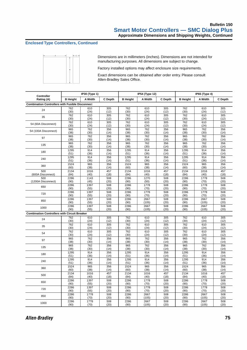
Bulletin 150Smart Motor Controllers — SMC Dialog Plus
75
Approximate Dimensions and Shipping Weights, Continued
Enclosed Type Controllers, Continued
Dimensions are in millimeters (inches). Dimensions are not intended for manufacturing purposes. All dimensions are subject to change.
Factory installed options may affect enclosure size requirements.
Exact dimensions can be obtained after order entry. Please consultAllen-Bradley Sales Office.
Controller Rating (A)
IP30 (Type 1) IP54 (Type 12) IP65 (Type 4)
B Height A Width C Depth B Height A Width C Depth B Height A Width C Depth
Combination Controllers with Fusible Disconnect
24 762(30)
610(24)
305(12)
762(30)
610(24)
305(12)
762(30)
610(24)
305(12)
35 762(30)
610(24)
305(12)
762(30)
610(24)
305(12)
762(30)
610(24)
305(12)
54 (60A Disconnect) 762(30)
610(24)
305(12)
762(30)
610(24)
305(12)
762(30)
610(24)
305(12)
54 (100A Disconnect) 965(38)
762(30)
356(14)
965(38)
762(30)
356(14)
965(38)
762(30)
356(14)
97 965(38)
762(30)
356(14)
965(38)
762(30)
356(14)
965(38)
762(30)
356(14)
135 965(38)
762(30)
356(14)
965(38)
762(30)
356(14)
965(38)
762(30)
356(14)
180 1295(51)
914(36)
356(14)
1295(51)
914(36)
356(14)
1295(51)
914(36)
356(14)
240 1295(51)
914(36)
356(14)
1295(51)
914(36)
356(14)
1295(51)
914(36)
356(14)
360 1524(60)
965(38)
356(14)
1524(60)
965(38)
356(14)
1524(60)
965(38)
356(14)
500(600A Disconnect)
2134(84)
1016(40)
457(18)
2134(84)
1016(40)
457(18)
2134(84)
1016(40)
457(18)
500(1200A Disconnect)
2286(90)
1143(45)
508(20)
2286(90)
1270(50)
508(20)
2286(90)
1778(70)
508(20)
650 2286(90)
1397(55)
508(20)
2286(90)
1778(70)
508(20)
2286(90)
1778(70)
508(20)
720 2286(90)
1397(55)
508(20)
2286(90)
1778(70)
508(20)
2286(90)
1778(70)
508(20)
850 2286(90)
1397(55)
508(20)
2286(90)
2667(105)
508(20)
2286(90)
2667(105)
508(20)
1000 2286(90)
1397(55)
508(20)
2286(90)
2667(105)
508(20)
2286(90)
2667(105)
508(20)
Combination Controllers with Circuit Breaker
24 762(30)
610(24)
305(12)
762(30)
610(24)
305(12)
762(30)
610(24)
305(12)
35 762(30)
610(24)
305(12)
762(30)
610(24)
305(12)
762(30)
610(24)
305(12)
54 762(30)
610(24)
305(12)
762(30)
610(24)
305(12)
762(30)
610(24)
305(12)
97 965(38)
762(30)
356(14)
965(38)
762(30)
356(14)
965(38)
762(30)
356(14)
135 965(38)
762(30)
356(14)
965(38)
762(30)
356(14)
965(38)
762(30)
356(14)
180 1295(51)
914(36)
356(14)
1295(51)
914(36)
356(14)
1295(51)
914(36)
356(14)
240 1295(51)
914(36)
356(14)
1295(51)
914(36)
356(14)
1295(51)
914(36)
356(14)
360 1524(60)
965(38)
356(14)
1524(60)
965(38)
356(14)
1524(60)
965(38)
356(14)
500 2134(84)
1016(40)
457(18)
2134(84)
1016(40)
457(18)
2134(84)
1016(40)
457(18)
650 2286(90)
1397(55)
508(20)
2286(90)
1778(70)
508(20)
2286(90)
1778(70)
508(20)
720 2286(90)
1397(55)
508(20)
2286(90)
1778(70)
508(20)
2286(90)
1778(70)
508(20)
850 2286(90)
1778(70)
508(20)
2286(90)
2667(105)
508(20)
2286(90)
2667(105)
508(20)
1000 2286(90)
1778(70)
508(20)
2286(90)
2667(105)
508(20)
2286(90)
2667(105)
508(20)
A C
B


Publication 0150 – 1.1.1 — January, 1998 (Supersedes Pub. 0150-1.1.1 — March, 1994) Copyright, Printed in U.S.A.