Smart antennas for mobile communication systems: benefits and challenges
11
Smart antennas for mobile communication systems: benefits and challenges by G. V. Tsoulos Spatial filtering using adaptive or smart antennas has emerged as a piromising technique to improve the performance of cellular mobile systems. This paper presents an overview of smart antennas in terms of key characteristics, options, challenges and benefits, in the context of current, but also with a view towards future, generation persona I commun icat ion systems. 1 Introduction Over the last few years the demand for service provision via the wireless communication bearer has risen beyond all expectations. If the extraordinary fact that worldwide some half a billion subscribers to mobile networks are predicted by the year 2000 is put in the context of third generation system requirements (UMTS, IMT2000) ’, then the most demanding technological challenge emerges: the need to increase the spectrum efficiency of wireless networks. While great effort in current (second) generation wireless communication systems has been directed towards the development of modulation, coding and protocols, antenna-related technology has received significantly less attention up to now. To achieve the ambitious requirements introduced for future wireless systems, new ‘intelligent’ or ‘self-configured’ and highly efficient systems will most certainly be required. In the pursuit of schemes that will solve these problems, attenlion has recently turned to spatial filtering methods using advanced antenna techniques: adaptive or smart antennas. Filtering in the space domain can separate spectrally and temporally overlapping signals from multiple mobile units, and hence the spatial dimension can be exploited as a hybrid multiple access technique complementing FDMA, TDMA and CDMA. 2 Smart antenna approaches Three main categories of smart antennas may be defined based on how they produce their response: switched beam, direction finding, optimum combining. The AEF BER BS BSRF CDMA CIR D CS 1800 dBd DSCDMA DSP DTX EIRP FCC FDD FDMA GSM IMT2000 Abbreviations = area improvement factor = bit error ratio = base station = base station reduction factor = code division multiple access = carrier-to-interference ratio = digital communication system at = decibels above dipole = direct sequence CDMA = digital signal processing = discontinuous transmission = effective isotropic radiated power = Federal Communications Commission = frequency division duplex = frequency division multiple access = Global System for Mobile = International Mobile Telecommunica- tions for the year 2000 1800 MHz IS54/95 LOS MMSE MS NLOS PA REF SDMA SFIR SINR SNR TDD TDMA UMTS = interim standard (of the American National Standards Institute and referring to an accepted industry standard) for TDMA (54) or CDMA (95) = line of sight = minimum mean square error = mobile station = non line of sight = power amplifier = range extension factor = space division multiple access = spatial filtering for interference = signal-to-interference-plus-noiseratio = signal-to-noise ratio = time division duplex = time division multiple access = Universal Mobile Telecommunications reduction System 84 ELECTRONICS & COMMUNICATION ENGINEERING JOIJRNAL APRIL 1999
Transcript of Smart antennas for mobile communication systems: benefits and challenges

Smart antennas for mobile communication systems: benefits and challenges
by G. V. Tsoulos
Spatial filtering using adaptive or smart antennas has emerged as a piromising technique to improve the performance of cellular mobile systems. This paper presents an overview of smart antennas in terms of key characteristics, options, challenges and
benefits, in the context of current, but also with a view towards future, generation persona I com mu n icat ion systems.
1 Introduction
Over the last few years the demand for service provision via the wireless communication bearer has risen beyond all expectations. If the extraordinary fact that worldwide some half a billion subscribers to mobile networks are predicted by the year 2000 is put in the context of third generation system requirements (UMTS, IMT2000) ’, then the most demanding technological challenge emerges: the need to increase the spectrum efficiency of wireless networks. While great effort in current (second) generation wireless communication systems has been directed towards the development of modulation, coding and protocols, antenna-related technology has received significantly less attention up to now. To achieve the ambitious requirements introduced for future wireless systems, new
‘intelligent’ or ‘self-configured’ and highly efficient systems will most certainly be required. In the pursuit of schemes that will solve these problems, attenlion has recently turned to spatial filtering methods using advanced antenna techniques: adaptive or smart antennas. Filtering in the space domain can separate spectrally and temporally overlapping signals from multiple mobile units, and hence the spatial dimension can be exploited as a hybrid multiple access technique complementing FDMA, TDMA and CDMA.
2 Smart antenna approaches
Three main categories of smart antennas may be defined based on how they produce their response: switched beam, direction finding, optimum combining. The
AEF BER BS BSRF CDMA CIR D CS 1800
dBd DSCDMA DSP DTX EIRP FCC FDD FDMA GSM IMT2000
Abbreviations = area improvement factor = bit error ratio = base station = base station reduction factor = code division multiple access = carrier-to-interference ratio = digital communication system at
= decibels above dipole = direct sequence CDMA = digital signal processing = discontinuous transmission = effective isotropic radiated power = Federal Communications Commission = frequency division duplex = frequency division multiple access = Global System for Mobile = International Mobile Telecommunica-
tions for the year 2000
1800 MHz
IS54/95
LOS MMSE MS NLOS PA REF SDMA SFIR
SINR SNR TDD TDMA UMTS
= interim standard (of the American National Standards Institute and referring to an accepted industry standard) for TDMA (54) or CDMA (95)
= line of sight = minimum mean square error = mobile station = non line of sight = power amplifier = range extension factor = space division multiple access = spatial filtering for interference
= signal-to-interference-plus-noise ratio = signal-to-noise ratio = time division duplex = time division multiple access = Universal Mobile Telecommunications
reduction
System
84 ELECTRONICS & COMMUNICATION ENGINEERING JOIJRNAL APRIL 1999
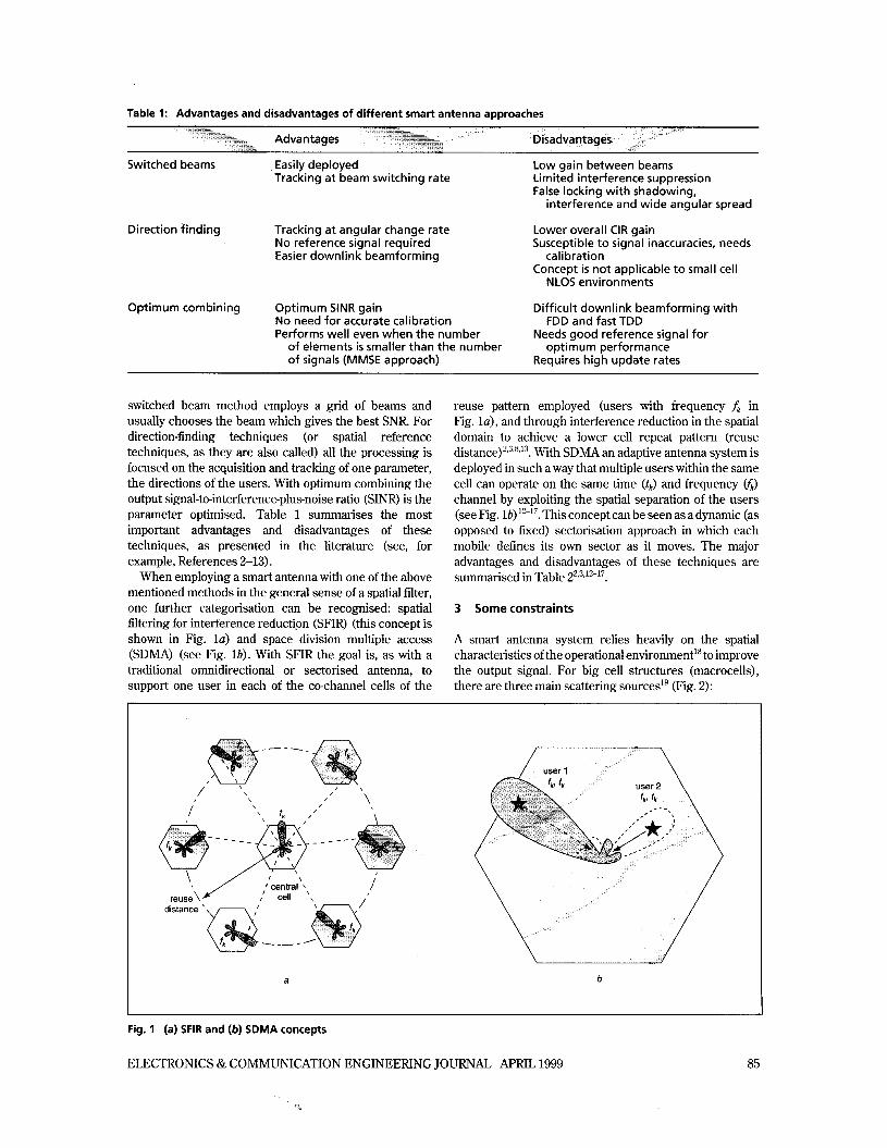
Table 1: Advantages and disadvantages of different smart antenna approaches
Switched beams Easily deployed Low gain between beams Tracking at beam switching rate Limited interference suppression
False locking with shadowing, interference and wide angular spread
Lower overall CIR gain Susceptible to signal inaccuracies, needs
Concept is not applicable to small cell
Optimum combining Optimum SINR gain Difficult downlink beamforming with
Direction finding Tracking a t angular change rate No reference signal required Easier downlink beamforming Cali bration
NLOS environments
No need for accurate calibration Performs well even when the number
FDD and fast TDD Needs good reference signal for
optimum performance Requires high update rates
of elements is smaller than the number of signals (MMSE approach)
switched beam method employs a grid of beams and usually chooses the beam which gives the best SNR For direction-finding techniques (or spatial reference techniques, as they are also called) all the processing is focused on the acquisition and tracking of one parameter, the directions of the users. With optimum combining the output signal-to-interference-plus-noise ratio (SINR) is the parameter optimised. Table 1 summarises the most important advantages and disadvantages of these techniques, as presented in the literature (see, for example, References 2-13).
When employing a smart antenna with one of the above mentioned methods in the general sense of a spatial filter, one further categorisation can be recognised: spatial filtering for interference reductipn (SFIR) (this concept is shown in Fig. la ) and space division multiple access (SDMA) (see Fig. l b ) . With SFIR the goal is, as with a traditional omnidirectional or sectorised antenna, to support one user in each of the co-channel cells of the
reuse pattern employed (users with frequency f k in Fig. l a ) , and through interference reduction in the spatial domain to achieve a lower cell repeat pattern (reuse d i s t a n ~ e ) ~ ~ ~ ' ~ " ~ . With SDMA an adaptive antenna system is deployed in such a way that multiple users within the same cell can operate on the same time (tJ and frequency v6) channel by exploiting the spatial separation of the users (see Fig. lb) 12-17. This concept can be seen as a dynamic (as opposed to fixed) sectorisation approach in which each mobile defines its own sector as it moves. The major advantages and disadvantages of these techniques are summarised in Table 22,3,'2-'7.
3 Some constraints
A smart antenna system relies heavily on the spatial characteristics of the operational environment" to improve the output signal. For big cell structures (macrocells), there are three main scattering sources1g (Fig. 2):
\
_ - - - -
I reuse\%
distance
a b
Fig. 1 (a) SFIR and (b) SDMA concepts
ELECTRONICS & COMMUNICATION ENGINEERING JOURNAL APRIL 1999 85
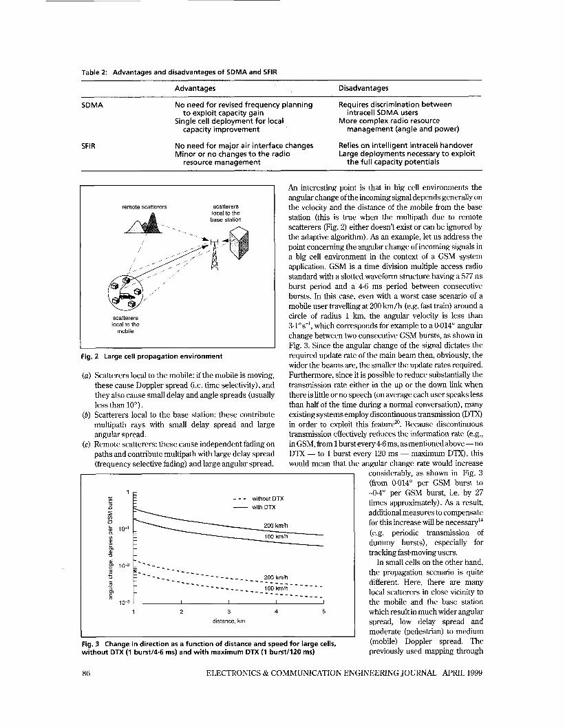
Table 2: Advantages and disadvantages of SDMA and SFIR
Advantages Disadvantages
SDMA
SFIR
No need for revised frequency planning
Single cell deployment for local
No need for major air interface changes Minor or no changes to the radio
Requires discrimination between
More complex radio resource
Relies on intelligent intracell handover Large deployments necessary to exploit
t o exploit capacity gain
capacity improvement
intracell SDMA users
management (angle and power)
resource management the full capacity potentials
remote scatterers scatterers local to the
base station
scatterers local to the
mobile
I
Fig. 2 Large cell propagation environment
(U ) Scatterers local to the mobile: if the mobile is moving, these cause Doppler spread (i.e. time selectivity), and they also cause small delay and angle spreads (usually less than 10").
(b) Scatterers local to the base station: these contribute multipath rays with small delay spread and large angular spread.
(c) Remote scatterers: these cause independent fading on paths and contribute multipath with large delay spread (frequency selective fading) and large angular spread.
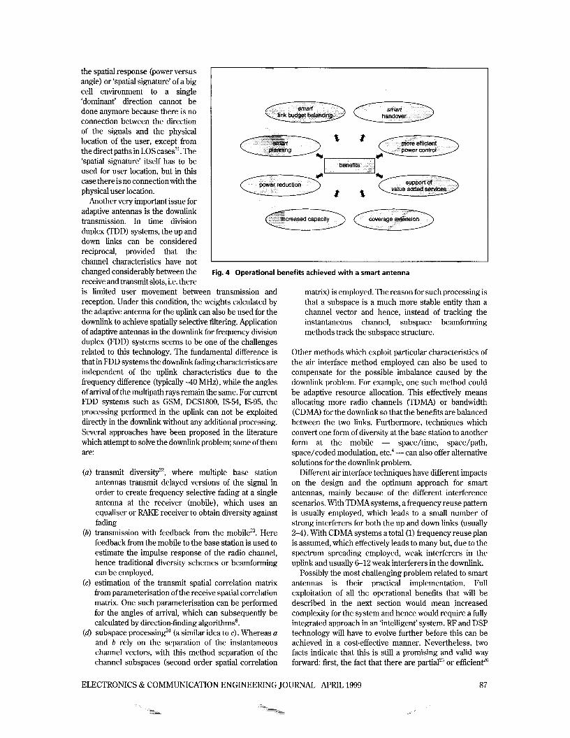
An interesting point is that in big cell environments the angular change of the incoming signal depends generally on the velocity and the distance of the mobile from the base station (this is true when the multipath due to remote scatterers (Fig. 2) either doesn't exist or can be ignored by the adaptive algorithm). As an example, let us address the point concerning the angular change of incoming signals in a big cell environment in the context of a GSM system application. GSM is a time division multiple access radio standard with a slotted waveform structure having a 577 ns burst period and a 4.6 ms period between consecutive bursts. In this case, even with a worst case scenario of a mobile user travelling at 200 km/h (e.g. fast train) around a circle of radius 1 km, the angular velocity is less than 3-los-', which corresponds for example to a 0.014" angular change between two consecutive GSM bursts, as shown in Fig. 3. Since the angular change of the signal dictates the required update rate of the main beam then, obviously, the wider the beams are, the smaller the update rates required. Furthermore, since it is possible to reduce substantially the transmission rate either in the up or the down link when there is little or no speech (on average each user speaks less than half of the time during a normal conversation), many existing systems employ discontinuous transmission (DTX) in order to exploit this feature". Because discontinuous transmission effectively reduces the information rate (e.g., in GSM, from 1 burst every 4.6 ms, as mentioned above - no DTX - to 1 burst every 120 ms - maximum DTX), this would mean that the angular change rate would increase
considerably, as shown in Fig. 3 (from 0.014" per GSM burst to
;; I E - - - without DTX - with DTX
p! m
- - - - - - - - - _ _ _ _ _ _ 200 kmh
io0 kmlh L m - - - - - - - - - - m - - - - - -
- - - - - - - - - _ _ _ _ _ _ _ _ - - - _
m
I 0-3 1 2 3 4 5
distance. km
Fig. 3 Change in direction as a function of distance and speed for large cells, without DTX (1 burstl4.6 ms) and with maximum DTX (1 burstll20 ms)
-0-4" per GSM burst, i.e. by 27 times approximately). As a result, additional measures to compensate for this increase will be ne~essary '~ (e.g. periodic transmission of dummy bursts), especially for tracking fast-moving users.
In small cells on the other hand, the propagation scenario is quite different. Here, there are many local scatterers in close vicinity to the mobile and the base station which result in much wider angular spread, low delay spread and moderate (pedestrian) to medium (mobile) Doppler spread. The previously used mapping through
86 ELECTRONICS & COMMUNICATION ENGINEERING JOURNAL APRIL 1999
the spatial response (power versus angle) or ‘spatial signature’ of a big cell environment to a single ‘dominant’ direction cannot be done anymore because there is no connection between the direction of the signals and the physical location of the user, except from the direct paths in LOS cases”. The ‘spatial signature’ itself has to be used for user location, but in this case there is no connection with the physical user location.
Another very important issue for adaptive antennas is the downlink transmission. In time division duplex (TDD) systems, the up and down links can be considered reciprocal, provided that the channel characteristics have not changed considerably between the receive and transmit slots, i.e. there
I
Fig. 4 Operational benefits achieved with a smart antenna
is limited user movement between transmission and reception. Under this condition, the weights calculated by the adaptive antenna for the uplink can also be used for the downlink to achieve spatially selective filtering. Application of adaptive antennas in the downlink for frequency division duplex (FDD) systems seems to be one of the challenges related to this technology. The fundamental difference is that in FDD systems the downlink fading characteristics are independent of the uplink characteristics due to the frequency difference (typically -40 MHz) , while the angles of arrival of the multipath rays remain the same. For current FDD systems such as GSM, DCS1800, IS%, IS95, the processing performed in the uplink can not be exploited directly in the downlink without any additional processing. Several approaches have been proposed in the literature which attempt to solve the downlink problem; some of them are:
(U ) transmit diversi@’, where multiple base station antennas transmit delayed versions of the signal in order to create frequency selective fading at a single antenna at the receiver (mobile), which uses an equaliser or RAKE receiver to obtain diversity against fading
(b) transmission with feedback from the mobilez3. Here feedback from the mobile to the base station is used to estimate the impulse response of the radio channel, hence traditional diversity schemes or beamforming can be employed.
(c) estimation of the transmit spatial correlation matrix from parameterisation of the receive spatial correlation matrix. One such parameterisation can be performed for the angles of arrival, which can subsequently be calculated by direction-finding algorithmss.
(6) subspace pr0cessing2~ (a similar idea to c). Whereas a and b rely on the separation of the instantaneous channel vectors, with this method separation of the channel subspaces (second order spatial correlation
matrix) is employed. The reason for such processing is that a subspace is a much more stable entity than a channel vector and hence, instead of tracking the instantaneous channel, subspace beamforming methods track the subspace structure.
Other methods which exploit particular characteristics of the air interface method employed can also be used to compensate for the possible imbalance caused by the downlink problem. For example, one such method could be adaptive resource allocation. This effectively means allocating more radio channels (TDMA) or bandwidth (CDMA) for the downlink so that the benefits are balanced between the two links. Furthermore, techniques which convert one form of diversity at the base station to another form at the mobile - space/time, space/path, space/coded modulation, etc.4 -can also offer alternative solutions for the downlink problem.
Di€ferent air interface techniques have different impacts on the design and the optimum approach for smart antennas, mainly because of the different interference scenarios. With TDMA systems, a frequency reuse pattern is usually employed, which leads to a small number of strong interferers for both the up and down links (usually 2-4). With CDMA systems a total (1) frequency reuse plan is assumed, which effectively leads to many but, due to the spectrum spreading employed, weak interferers in the uplink and usually 6-12 weak interferers in the downlink.
Possibly the most challenging problem related to smart antennas is their practical implementation. Full exploitation of all the operational benefits that will be described in the next section would mean increased complexity for the system and hence would require a fully integrated approach in an ‘intelligent’ system. RF and DSP technology will have to evolve further before this can be achieved in a cost-effective manner. Nevertheless, two facts indicate that this is still a promising and valid way forward: first, the fact that there are partialz5 or efficienP6
ELECTRONICS & COMMUNICATION ENGINEERING JOURNAL APRIL 1999
~ ~
~ ~
~~ ~ ~ ~ ~ ~
~ ~ ~ ~ ~ ~
~ ~
~
87
More efficient power control -smart handover 1
0.9 1
5 0 5
Z 0 4 x
g 0 2 0 1
0 1 I I I I J -20 -15 -10 -5 0 5 10 15
SNR. dB
Fig. 5 Probability of detection when a matched filter is employed for each antenna element
implementations that can be employed in real systems to reduce complexity and, second, the fact that by the time mobile communication systems are ready to fully support smart antennas (most probably with 3rd generation systems) the required technology will be available and mature enough to fully support adaptive antennasz7 (assuming Moore’s law). Furthermore, although current implementation and installation costs are thought to be high for smart antenna systems in comparison with traditional omnidirectional or sectorised schemes, if the range-capacity gains and the other benefits that will be discussed in the next section are included in the overall cost calculations, then it becomes obvious that this technology is rather economical even for today’s systems.
The diversity gain offered by an antenna array reduces the fading of the radio signal and hence the power control requirements are eased. With information about the location and speed of a mobile user, the decision as to which cell to hand the user to is a much easier task. Combination of this kind of information with the handover process can ultimately lead to a ‘smart’ instead of ‘soft’ or ‘hard’ handover. Furthermore, in order to support the soft handoff quality enhancement technique for DSCDMA within a mixed cell environment, all cell types have to operate on identical carrier frequencies. One possible way of achieving the RF power balancing within each area of a mixed cell scenario needed to provide seamless handover and simultaneously avoiding the near-far effect is to exploit the spatial filtering properties offered by an adaptive antennaz8.
Support of value added services
Better signal quality - higher data rates In noise or interference limited environments, the gain
that can be achieved with an antenna array can be exchanged for signal quality enhancement, i.e. lower BER. This is demonstrated in Figs. 5 and 6. Fig. 5 shows the probability of detection for the case where a matched filter (a detector which maximises the probability of detection with additive noise) is employed for each array element. The probability of detection in this case is ”:
4 Operational benefits wi th smart antennas
Fig. 4 shows an overview of the operational benefits that can be achieved from the deployment of an adaptive antenna in a mobile communication network’. Each of these benefits is discussed in greater detail below.
where Q(.) is the Q function, Po is the probability of detection, PF is the threshold probability of false alarm, M is the number of elements and SNR the signal-to-noise ratio. From Fig. 5 it can be seen that the detection performance can be significantly enhanced with an
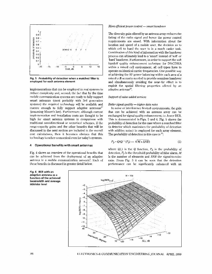
Fig. 6 BER with an adaptive antenna as a function of the achieved beamwidth and average sidelobe level
N = 100
-1 0
88 ELECTRONICS & COMMUNICATION ENGINEERING JOURNAL APRIL 1999
antenna array. For example, for 0 dB SNR, there is 10% probability of detection with a single element, 20%with two elements, 35% with four, 65% with eight, 85% with twelve, 95% with sixteen and almost 100% with twenty.
Fig. 6 shows another example, this time for a DSCDMA system, where the following approximate formula for the BER is used3':
Pb = Q ( d 3 SF x SIRonni x k-') (2)
where SF is the spreading factor (64), SIRomni is the signal-to-interference ratio with an omnidirectional antenna, and
BW 360 ( ::) k=- -+SLL 1--- (3)
with BW and SLL the ideal or effective* beamwidth (degrees) and average sidelobe level (linear values), respectively. Fig. 6 shows a plot of eqn, 2 for the case of 100 users per cell (N) in a multitier system (4 tiers) for values of achieved beamwidth and sidelobe level between 10" and 30°, and -10 dB and -20 dB, respectively. As an example from Fig. 6, if the smart antenna that is employed at the base station of the central cell can achieve a radiation pattern with a beamwidth of 20" (ideal or effective), then an improvement of 1-7 orders of magnitude for the BER can be accomplished with average sidelobe levels (ideal or effective) between-10 dB and -20 dB, respectively. Obviously, the sidelobe level achieved has such a profound effect on the BER results because it reduces the interference received at that region and hence improves the overall SIR, as seen from eqns. 2 and 3.
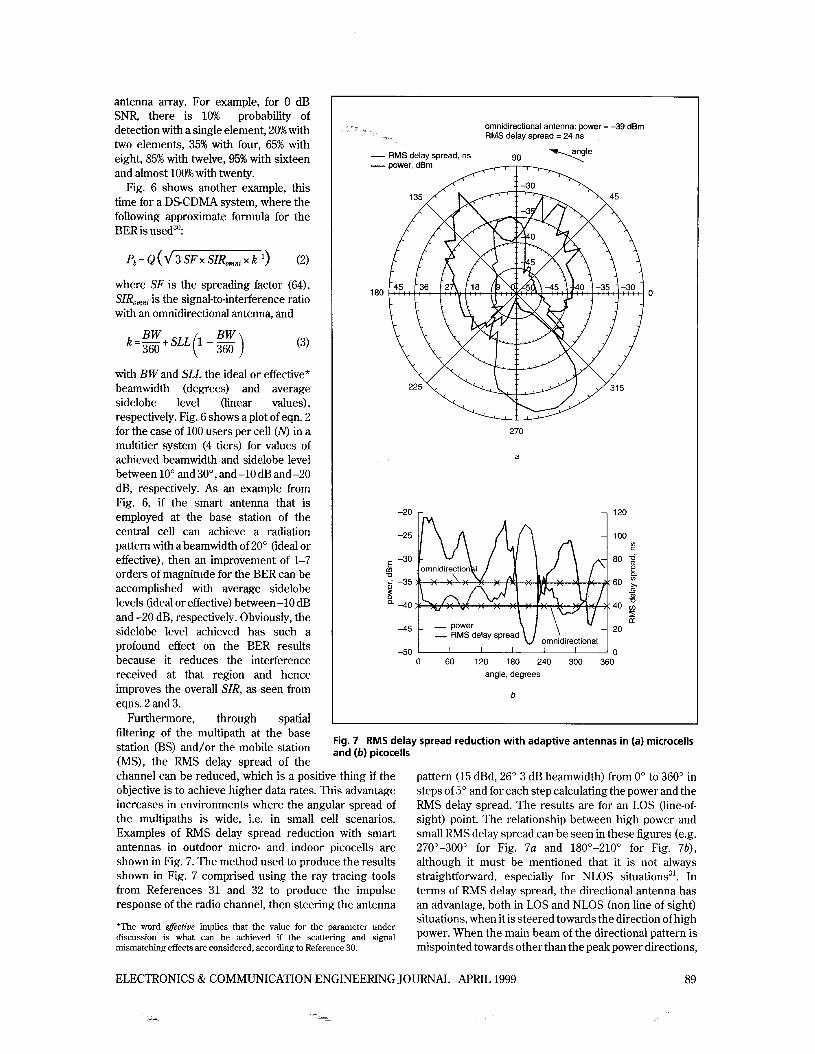
Furthermore, through spatial filtering of the multipath at the base station (BS) and/or the mobile station (MS), the RMS delay spread of the
omnidirectional antenna: power = -39 dBm RMS delay spread = 24 ns
- RMS delay spread, ns -
180
270
a
-20 r
IM 1
omnidirectional
__ power _. RMS delay spread
45 t -Fin I I I I I I _ _
0 60 120 180 240 300 360 angle, degrees
b
120
100
80 2 a,
(I)
Q
60 ;
z - a,
40
20
0
Fig. 7 RMS delay spread reduction with adaptive antennas in (a) microcells and (b) picocells
channel can be reduced, which is a positive thing if the objective is to achieve higher data rates. This advantage increases in environments where the angular spread of the multipaths is wide, i.e. in small cell scenarios. Examples of RMS delay spread reduction with smart antennas in outdoor micro- and indoor picocells are shown in Fig. 7. The method used to produce the results shown in Fig. 7 comprised using the ray tracing tools from References 31 and 32 to produce the impulse response of the radio channel, then steering the antenna
pattern (15 dBd, 26" 3 dB beamwidth) from 0" to 360" in steps of 5" and for each step calculating the power and the RMS delay spread. The results are for an LOS (line-of- sight) point. The relationship between high power and small RMS delay spread can be seen in these figures (e.g. 270"-300" for Fig. 7a and 180"-210" for Fig. 7b), although it must be mentioned that it is not always straightforward, especially for NLOS situations3'. In terms of RMS delay spread, the directional antenna has an advantage, both in LOS and NLOS (non line of sight) situations, when it is steered towards the direction of high power. When the main beam of the directional pattern is mispointed towards other than the peak power directions,
*The word effective implies that the value for the parameter under discussion is what can be achieved if the scattering and signal mismatching effects are considered, according to Reference 30.
ELECTRONICS & COMMUNICATION ENGINEERING JOURNAL APRIL 1999 89
desired Jser --S interferers 9 0 80
60 -1 0
40
20 -20
E O -30
-40
a,
m -20
-40
-60 -50
-80
0 2 4 6 8 point
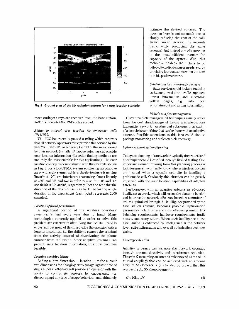
Fig. 8 Ground plan of the 3 0 radiation pattern for a user location scenario
optimise the desired outcome. The question here is not so much one of simply reducing the cost of the calls (which would increase the network traffic while producing the same revenue), but instead one of improving in the most efficient manner the capacity of the system. Also, this technique enables tariff plans to be tailored to individual user needs, e.g. by providing low-cost zones when the user is in his preferred zone.
On-demand location-specific services Such services could include roadside
assistance, real-time traffic updates, tourist information and electronic yellow pages, e.g. with local entertainment and dining information.
more multipath rays are received from the base station, and this increases the RMS delay spread.
Ability to support user location for emergency calls (91 1/999)
The FCC has recently passed a ruling which requires that all network operators must provide this service by the year 2001, with 125 m accuracy for 67% of the area covered by their network (initially). Adaptive antennas can provide user location information (direction-finding methods are naturally the most suitable for this application). The user location concept is demonstrated with the example shown in Fig. 8, for a DSCDMA system employing an adaptive array with eight elements. Here, the desired user is moving linearly at -20", two interferers are moving almost linearly at -60" and 30" and two interferers start from 0' and 60" and finish at 60" and 0", respectively. It can be seen that the direction of the desired user can be found for the whole duration of the experiment (each point represents 1000 samples).
Location of faud perpetrators A significant portion of the wireless operators'
revenues is lost every year due to fraud. Many technologies currently applied in order to solve this problem are effective in identifying the fact that fraud is occurring but none of them provides the operator with a long-term solution, i.e. the ability to remove the criminal from the activity, instead of deactivating the phone number from the switch. Since adaptive antennas can provide user location information, this now becomes feasible.
Location-sensitive billing Adding a third dimension - location - to the current
two dimensions for charging rates (usage against time of day, i.e. peak, off-peak) will provide an operator with the ability to control its network by encouraging (or discouraging) any type of usage behaviour, and ultimately
Vehicle and fleet management Current vehicle management techniques usually suffer
from the cost disadvantage of having a single-purpose transmitter network. Location and subsequent navigation of avehicle is something that can be done with an adaptive antenna. Possible extensions to this idea could also be package monitoring and stolen vehicle recovery.
Optimum smart system planning
Today the planning of a network is typically theoretical and once implemented is verified through limited testing. One important element missing from this planning process is that designers never really know where wireless devices are located when a specific cell site is handling a problematic call. Obviously this situation can be greatly improved with the user location capabilities of adaptive antennas.
Furthermore, with an adaptive antenna an advanced intelligent network, which will lessen the planning burden and improve the network efficiency based on a number of criteria optimised through the intelligence provided by the base station antenna, becomes possible. Optimisation parameters include intra- and intercell reuse planning, link balancing requirements, handover requirements, traftic density and many others. When such intelligence at the base station is enhanced by intelligence at the network level, self-configuration and overall optimisation becomes viable.
Coverage extension
Adaptive antennas can increase the network coverage through antenna directivity and interference reduction. The gain G (assuming an antenna efficiency of 100% and no mutual coupling) that can be achieved with an antenna array of M elements is (it can also be proved that this represents the SNR improvement) :
90 ELECTRONICS & COMMUNICATION ENGINEERING JOURNAL APRIL 1999

The additional gain (compared to the standard element gain) can obviously be exploited for range extension. With small angular spread and single slope path loss with exponent n, the range extension factor, REF, can be calculated as:
or, with the Hata path loss modeP3:
where r, and r, are the default (with a single element) and extended (with multiple elements) ranges, respectively. The area improvement factor, AEF, is:
AEF= - = R E F 2 (:I The inverse of the area extension factor represents the reduction factor in the number of base stations (BSRF) needed to serve the same area as with a single element. Obviously, one can get the full range extension from the directivity of the array when the angular spread of the signal is less than the antenna beamwidth (otherwise the desired signal is reduced). Fig. 9 shows that with ten antenna elements (10 dB of SNR improvement) the range can be almost doubled and the area almost quadrupled, or the number of base stations can be reduced to almost 25% of the original number. Also, it can be seen that with smaller path loss exponents (the curve for n=3 in Fig. 9) the improvement factors will be higher, i.e. the improvements will be higher in LOS as compared to NLOS scenarios. Also, the calculated range extension with the Hata path loss model is between the predictions for path loss exponents of 3 and 4.
Reduced transmit power
Limitations on the maximum EIRP (effective isotropic radiated power) introduced by standards could mean that the array gain cannot be exploited for coverage or area extension. Also, recent public worries over health issues originating from exposure to electromagnetic radiation (no matter how reasonable or unreasonable this may be) will almost certainly force the governing/standardisation bodies to change the current radiation standards in the future and adopt a lower emission policy, in particular for the mobile handsets. In such cases, one could exploit the base station array gain to reduce the power transmitted by the mobile. This reduction is also beneficial because it relaxes the battery requirements and hence it can increase the talk times or reduce the size/weight of the handsets.
Furthermore, if the received power requirement at the mobile remains the same with an Melement array at the base station, then the output power from the base station power amplifiers (PAS) can be reduced by M -', which will reduce the total transmitted power from the array by M-'. The explanation for this (see, for example, Reference 34) is that the base station now employs MPAs and can simultaneously exploit the directivity of the array. Ten antenna elements will reduce the total transmitted power by 10 dB, while the output of each PA will be reduced by 20 dB. The latter has obvious cost implications, since the high-power ampliliers are expensive hardware components of a system.
Smart link budget balancing
Examination of the up/down link budgets reveals an imbalance which originates from the difference in the power amplifiers employed at the two ends. This imbalance is usually around 10-20 dB and its actual value depends on the PA used at the base station site. As an example consider a case where there is a 13 dBW PAwith a 17 dBi antenna, giving 1 kW EIRP at the base station (this
SNR improvement 10 13 0
5
4 b s E 3
E 8 k 2 E
1
n " I 2 4 6 8 10 12 14 16 18 20
number of elements
Fig. 9 Range, area and base station reduction factors as a function of the number of elements and SNR improvement
ELECTRONICS & COMMUNICATION ENGINEERING JOURNAL APRIL 1999 91
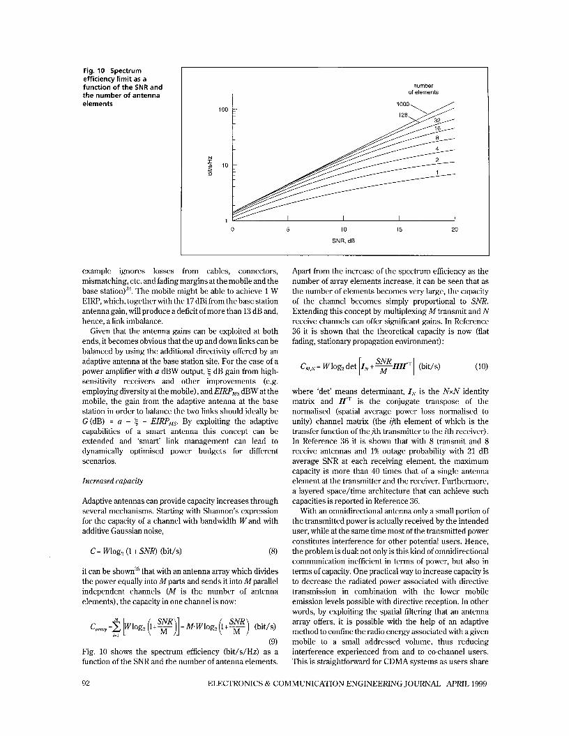
Fig. 10 Spectrum efficiency limit as a function of the SNR and the number of antenna elements
number of elements
100
N
10 ?
1 0 5 10 15 20
SNR, dB
example ignores losses from cables, connectors, mismatching, etc. and fading margins at the mobile and the base station)”. The mobile might be able to achieve 1 W EIRP, which, together with the 17 dBi from the base station antenna gain, will produce a deficit of more than 13 dB and, hence, a link imbalance.
Given that the antenna gains can be exploited at both ends, it becomes obvious that the up and down links can be balanced by using the additional directivity offered by an adaptive antenna at the base station site. For the case of a power amplifier with a dBW output, 5 dB gain from high- sensitivity receivers and other improvements (e.g. employing diversity at the mobile), and EZRPMs dBW at the mobile, the gain from the adaptive antenna at the base station in order to balance the two links should ideally be G(dB) = a - 5 - EZRPMs. By exploiting the adaptive capabilities of a smart antenna this concept can be extended and ‘smart’ link management can lead to dynamically optimised power budgets for different scenarios.
Increased capacity
Adaptive antennas can provide capacity increases through several mechanisms. Starting with Shannon’s expression for the capacity of a channel with bandwidth Wand with additive Gaussian noise,
c = mog2 (1 + SNR) (bit/$ (8)
it can be shown35 that with an antenna array which divides the power equally into M parts and sends it into Mparallel independent channels (M is the number of antenna elements), the capacity in one channel is now:
(9) Fig. 10 shows the spectrum efficiency (bit/s/Hz) as a function of the SNR and the number of antenna elements.
Apart from the increase of the spectrum efficiency as the number of array elements increase, it can be seen that as the number of elements becomes very large, the capacity of the channel becomes simply proportional to SNR. Extending this concept by multiplexing M transmit and N receive channels can offer significant gains. In Reference 36 it is shown that the theoretical capacity is now (flat fading, stationary propagation environment) :
where ‘det’ means determinant, IN is the NxN identity matrix and H*T is the conjugate transpose of the normalised (spatial average power loss normalised to unity) channel matrix (the ijth element of which is the transfer function of thejth transmitter to the ith receiver). In Reference 36 it is shown that with 8 transmit and 8 receive antennas and 1% outage probability with 21 dB average SNR at each receiving element, the maximum capacity is more than 40 times that of a single antenna element at the transmitter and the receiver. Furthermore, a layered spacehime architecture that can achieve such capacities is reported in Reference 36.
With an omnidirectional antenna only a small portion of the transmitted power is actually received by the intended user, while at the same time most of the transmitted power constitutes interference for other potential users. Hence, the problem is dual: not only is this kind of omnidirectional communication inefficient in terms of power, but also in terms of capacity. One practical way to increase capacity is to decrease the radiated power associated with directive transmission in combination with the lower mobile emission levels possible with directive reception. In other words, by exploiting the spatial filtering that an antenna array offers, it is possible with the help of an adaptive method to confine the radio energy associated with a given mobile to a small addressed volume, thus reducing interference experienced from and to co-channel users. This is straightforward for CDMA systems as users share
92 ELECTRONICS & COMMUNICATION ENGINEERING JOURNAL APRIL 1999

Table 3: Advantages and disadvantages of smart antennas and small cells for capacity improvement
the same bandwidth, and in a TDMA system it can be achieved through reduced reuse patterns or SDMA.
Another approach to increase capacity is through dynamic reuse planning. With user location information, channels can be assigned dynamically to areas of high user density and hence better capacity can be achieved.
The capacity enhancement achieved can be exploited in many ways, but one particular possible application is in reducing the need for very small cell sizes and consequently reducing the infrastructure costs. When considering the dilemma of whether to use adaptive antennas or smaller cells for capacity, the advantages/disadvantages shown in Table 3 can be mentioned2s3. Nevertheless, when the requirements of future generation, UMTStype systems are considered in terms of the performance measures capacity, coverage and services, then it is almost certain that small cell structures will be deployed in order to fulfil these requirements, possibly in combination with some sort of smart antenna technolod8.
5 Conclusions
This paper has provided an overview of the potential benefits and challenges of applying smart-antenna technology to mobile communication systems. The basic advantages and disadvantages of two different approaches to smart antennas ((a) SDMA/SFIR; (b) switched beam/direction finding/optimum combining), as they are presented in open literature, were highlighted. Then the importance of specific characteristics of the radio channel under different operational environments (e.g. large-small cells, indoor-outdoor) and interference scenarios (CDMA-TDMA) were discussed. The realisation of comparable up and down link gains along and the practical implementation of a fully integrated smart antenna system seem to be the two most challenging issues facing this technology at the moment. Although more efficient implementations will almost certainly be needed for future systems, partial implementations make the application of smart antennas to current generation systems possible. Furthermore, by the time that future generation systems are ready fully to support smart antennas, the development of RF and DSP technology will have reached such a level that complex implementations will be possible.
Exploiting different characteristics of smart antennas can lead to several operational benefits for a communication system. These benefits have been
discussed in the paper, and are summarised below:
0 coverage extension 0 increased capacity 0 efficient power control/smart handover
support of value added services (better signal quality, higher data rates, user location) optimum/smart system planning
0 reduced transmit power smart link budget balancing
Communication systems will exploit different advantages or mixtures of advantages offered by smart antennas depending on the maturity of the underlying system. Initially, for example, costs can be reduced by exploiting the range extension capabilities of smart antennas. Then, where there is a demand for increased capacity, costs can be further decreased by avoiding extensive use of small cells and instead exploiting the capability of smart antennas to increase capacity. Finally, more advanced systems (3rd generation) will be able to benefit from smart antenna systems, but it is almost certain that more sophisticated spacehime filtering appro ache^'^ will be necessary, especially as these systems become mature.
Acknowledgments
The author gratefully acknowledges the assistance of Professor J. P. McGeehan in every aspect of his research activities. Thanks are also due to Dr. G. Athanasiadou for her help and the provision of ray-tracing results.
References
RAPELI, J.: ‘UMTS: targets, system concept, and standardisation in a global framework‘, IEEE Pen. Commun., February 1995,2, (l), pp. 20-28 TSOULOS, G.: ‘Adaptive antenna technology’. IEE 3rd residential course on Digital Techniques in Radio Systems, University of Bristol, September 1997 MOGENSEN, P.: ‘System aspects of adaptive antennas for GSM. TSUNAMI Seminar, Aalborg University, 1997 PAULRAJ, A.: ‘Smart antenna in wireless communications: technology overview’. 4th Workshop on Smart Antennas in Wireless Mobile Communications, Stanford University, 1997 WINTERS, J.: ‘Signal acquisition and tracking with adaptive arrays in the digital mobile radio system IS54 with flat fading’, IEEE Trans. Veh. Technol., 1993, VT-42, pp. 377-384 NAGUIB, A., PAULRAJ, A., and KAILATH, T.: ‘Capacity improvement with base station antenna arrays in cellular CDMA’, IEEE Trans. Veh. Technol., 1994, VI-43, pp. 691-698
ELECTRONICS & COMMUNICATION ENGINEERING JOURNAL APRIL 1999 93

George Tsoulos received a Master’s degree in Electrical Engineering from the National Technical University of Athens (Greece) in 1992 and a PhD degree from the University at Bristol (UK) in 1996. Since 1993 he has been with the Centre for Communications Research at the University of Bristol. He has been involved in both the RACE and ACTS TSUNAMI projects and now the SUNBEAM pro- ject, all on adaptive antennas. He is currently a Research Fellow at the University of Bristol funded by the Higher Education Funding Council for England (HEFCE), working in the area of smart antenna techniques for future generation mobile communications. His research interests include radio propagation and network planning with adaptive antennas, performance of different adaptive antenna techniques, beamforming architectures, adaptive algorithms, and wideband mobile communication systems. Dr. Tsoulos is chairman of the Working Group 2b of the European action COST 260 on smart antennas, a member of the propagation subgroup of the Standardisation Group SIG1, COST 259 and its groups on directional channel modelling and frequency planning, and a member of the Technical Chamber of Greece.
Address: Centre for Communications Research, University of Bristol, Merchant Venturers Building, Woodland Road, Bristol BS8 lUB, UK. Emaik [email protected]
7 THOMPSON, J., GRANT, P., and MULGREW, B.: ‘Smart antenna arrays for CDMA systems’, IEEE Pers. Commun., October 1996,3, (5), pp. 16-25.
8 ZEITERBERG, P., and O’ITERSTEN, B.: ‘The spectrum efficiency of a base station antenna array system for spatially selective transmission’, IEEE Trans. Veh. Technol., 1995, Vl-
9 KENNEDY, J., and SULLIVAN, M.: ‘Direction finding and “smart antennas” using software radio architectures’, IEEE Commun. Mag., May 1995,33, (5), pp. 62-68.
lOLI, Y., FEUERSTEIN, M., and REUDINK, D.: ‘Performance evaluation of a cellular base station multi beam antenna’, IEEE Trans. Veh. Technol., 1997, Vl-46, pp. 1-9
11H0, M., STUBER, G., and AUSTIN, M.: ‘Performance of switched beam smart antennas for cellular radio systems’, IEEE Trans. Veh. Technol., 1998,Vl-47, pp. 10-19
12 TSOULOS, G. et al.: Wireless personal communications for the 21st century: European technological advances in adaptive antennas’, IEEE Commun. Mag., September 1997,44, (9), pp. 102-109
13 TSUNAMI Project Final Report, RZlOS/ERA/WP1.3/MR/P/ 096/b2,1996
14DAM, H.: ‘Smart antennas in the GSM system’. MSc thesis, Aalborg University, 1995
15TANGEMA”, M.: ‘Near-far effects in adaptive SDMA system’. 6th Int. Symposium on Personal, Indoor and Mobile Radio Communications, 1995, Toronto, Canada, pp. 1293-1297
16 FUHL, J., and MOLISCH, A.: ‘Capacity enhancement and BER in a combined SDMA/TDMA system’. Proc. 46th Vehicular Technology Conference, 1996, Atlanta, USA, 3, pp. 1481-1485
17 XU, G. et al.: ‘Experimental studies of space division multiple access schemes for spectral efficient wireless communications’. Proc. IEEE Int. Communications Conf., 1st-5th May 1994, New Orleans, USA, pp. 800-804
18WARD, C., SMITH, M., JEFFRIES, A., ADAMS, D., and HUDSON, J.: ‘Characterising the radio propagation channel
44, pp.651-660
for smart antenna systems’, Electron. Gommun. Eng. J., August
19 PAULRAJ, A., and PAPADIAS, C.: ‘Space-time processing for wireless communications’, IEEE Signal Process. Mag., November 1997, pp. 49-83
20 MOULY, M., and PAUTET, M.: ‘The GSM system for mobile communications’ (Cell & Syst., France, 1992)
21TSOULOS, G., and ATHANASIADOU, G.: ‘Extrapolation of field trial results to UMTS’. TSUNAMI I1 Deliverable, ACO20/UOB/Dl.S/DS/P/192/al, 1998
22 WINTERS, J.: ‘Two signalling schemes for improving the error performance of frequency division duplex (FDD) transmission systems using transmitter antenna diversity’. 43rd IEEE Vehicular Technology Conf., 18th-20th May 1993, Secaucus, NJ, USA, pp. 85-88
23GElUACH, D., and PAULRAJ, A.: ‘Adaptive transmitting antenna arrays with feedback’, IEEE Signal Process. Lett., October 1994,1, (lo), pp. 150-153
24 RAYLEIGH, G., DIGAVVI, S., JONES, V., and PAULRAJ, A.: ‘A blind adaptive transmit antenna algorithm for wireless communication’. Proc. IEEE Int. Communications Conf., 1995, 3, pp. 1495-1499
25WARD, C., HARGRAVE, P., and McWHIRTER, J.: ‘A novel algorithm and architecture for adaptive digital beamforming’, March 1986, IEEE Trans. Antennas Propag., 34, (3), pp. 338-346
26GOCKLER, H., and SCHEUERMA”, H.: ‘A modular approach to a digital 60channel transmultiplexer using directional filters’, IEEE Trans. Commun., July 1982, 30, (7), pp. 1588-1613
27 GEPPERT, L.: ‘Solid state’, IEEE Spectrum, Analysis & Forecast Issue onTechnology, January 1996, pp. 51-55
28TSOULOS, G., ATHANASIADOU, G., BEACH, M., and SWALES, S.: ‘Adaptive antennas for microcellular and mixed cell environments with DSCDMA’, Kluwer Wireless Pen. Commun. J., August 1998, WPC-7, (2/3), pp. 147-169
29 JOHNSON, D., and DUDGEON, D.: ‘Array signal processing’ (Prentice-Hall, USA, 1993)
3OTSOULOS, G.: ‘Approximate SIR and BER formulas for D S CDMA based on the produced radiation pattern characteristics with adaptive antennas’, Electron. Lett., 1998, pp. 1802-1804.
31ATHANASIADOU, G., NIX, A., and McGEEHAN, J.: ‘A ray tracing algorithm for microcellular wideband propagation modelling’. IEEE Vehicular Technology Conf., 1995, Chicago,
32 ATHANASIADOU, G., NIX, A., and McGEEHAN, J.: ‘Anew 3D indoor ray tracing model with particular reference to predictions of power and RMS delay spread’. IEEE Personal Indoor and Mobile Radio Conf., September 1995, Toronto, Canada, pp. 1161-1165
33HATA, M.: ‘Empirical formula for propagation loss in land mobile radio services’, IEEE Trans. Veh. Technol., 1980, VT-
34 COOPER, M., and GOLDBURG, M.: ‘Intelligent antennas: spatial division multiple access’. 1996 Annual Review of Communications, pp. 999-1002 (a copy can be obtained from http://www.arraycomm.com/) .
35ANDERSEN, J.: ‘Capacity of parallel channels’. TSUNAMI I1 Seminar, Aalborg University, 1997
36 FOSCHINI, G.: ‘Layered space-time architecture for wireless communication in a fading environment when using multi- element antennas’, Bell Labs Tech.J., Autumn 1996, pp. 41-59
1996,8, (4), pp. 191-200
USA, pp. 261-265
29, (3), pp.317-325
OIEE: 1999 First received 17th July 1998 and in final form 16th January 1999.
94 ELECTRONICS & COMMUNICATION ENGINEERING JOURNAL APRIL 1999