Small StudY--Compliant Metal/Ceramic Liner and Performance ... · StudY--Compliant Metal/Ceramic...
16
NASA USAAVSCOM , Technical Memorandum 873(4 Technical Report .- 6 . Small Gas Turbine Combustor Experimental StudY--Compliant Metal/Ceramic Liner and Performance Evaluation Waldo A. Acosmi o Propudion Directorate U.S. Army Aviation Research od Technology Activity-A VSCOM Lewis Research Center k and Carl T. Norgren10,l Lewis Research Center 00 DTIC Cleveland, Ohio ,.ECTE 0* I .oXoT C ; ... !i.,.. • e's" y t AI•AA•M•,SAE, and AE.: •: nso Repreoduce F; ImA6 ilk :,I. r 4- Reproduced From Best Available Copy
Transcript of Small StudY--Compliant Metal/Ceramic Liner and Performance ... · StudY--Compliant Metal/Ceramic...

NASA USAAVSCOM ,Technical Memorandum 873(4 Technical Report .-6 .
Small Gas Turbine Combustor ExperimentalStudY--Compliant Metal/Ceramic Linerand Performance Evaluation
Waldo A. Acosmio Propudion Directorate
U.S. Army Aviation Research od Technology Activity-A VSCOMLewis Research Center
k and
Carl T. Norgren10,lLewis Research Center 00 DTICCleveland, Ohio ,.ECTE
0* I .oXoT C ; ...
!i.,.. • e's" y t AI•AA•M•,SAE, and AE.: •:
nso Repreoduce F; ImA6 ilk:,I. r 4-
Reproduced FromBest Available Copy

SMALL GAS TURBINE COMBUSTOR EXPERIMENTAL STUDY - COMPLIANT METAL/CERAMIC LINER
AND PERFORMANCE EVALUATION
Waldo A. AcostaPropulsion DirectorateLewis Research Center D T IC
Cleveland, Ohio ELECTEand AUG I I W
Carl T. NorgrenNational Aeronautics and Space Administration
Lewis Research CenterCleveland, Ohio B
Abstract technology for applying the ceramic matrix conceptto combustor liners. This program is aimed at
Combustor research relating to the development identifying and evaluating promising concepts. Theof fuel efficient small gas turbine engines capable experimental studies were specifically formulatedof meeting future commercial and military aviation to:needs is currently underway at NASA Lewis. As partof this combustor research, a basic reverse-flow (1) Investigate design and off-design param-combustor has been used to investigate advanced eters which determine stable long life for compli-liner wall cooling techniques. Liner temperature, ant ceramic combustor liners.performance, and exhaust emissions of the experi-
s mental combustor utilizing compliant metal/ceramic (2) Investigate the aerothermal performancem liners were determined and compared with three pre- impact of replacing current technology film cooledLI viously reported combustors that featured: (1) louver liners with uncooled ceramics.
splash film-cooled liner walls; (2) transpirationcooled liner walls; and (3) counter-flow film (3) Identify high potential advanced compliantcooled panels. ceramic liner concepts.
Introduction For this study, a simplified compliant ceramicliner concept was selected to facilitate implemen-
Problems unique to small combustors were tation into research hardware. The design and fab-reviewed during a forum at NASA Lewis conducted by rication of the combustor aerothermodynamics wasA.D. Little, Inc. 1 The objective was to identify patterned afte• an existing NASA reverse-flow filmthe R&D effort which must be considered in the 1980 cooled design.5 To maintain internal flowto 1990 time frame to meet the critical needs for dynamics, the physical geometry, air-entry distri-small aircraft gas turbines. Combustor liner cool- bution, and combustor pressure drop across theing requirements were the prime concerns. Advance- liner were similar. The conventional existingments in gas turbine cycle efficiency and lowered splash film-cooled wall was designed using a one-specific fuel consumption are realized by increas- dimensional computational scheme assuming a steady-irg cycle pressure ratios and turbine inlet temper- state heat flux balance between the heat gained byature, and/or implementing either regenerative or the wall and the heat lost. Conduction within therecuperative cycles. Combustors operating at these wall and radiation interchange between the hotconditions require increased amounts of cooling walls were considered negligible.air. However, additional air is not available dueto the larger amounts required to increase turbine Documentation of liner cooling effectiveness,inlet temperature and for turbine cooling. The combustion efficiency, and emission index levelsremaining available air is hotter due to increased over a range of simulated flight conditions of apressure ratio and/or regenerative cycle operation. 16:1 compression pressure ratio gas turbine engineThis loss in heat sink capability is particularly with Jet A fuel was obtained.critical in the small combustor system due to theinherent high surface-to-volume ratio. Conse- Apparatusquently, improvement in coolant utilization ismandatory to ach;eve higher cycle efficiencies. Test Facility
In recent years there has been a rapid growth The combustor was mounted in duct A of thein research and development aimed at introducing test facility CEgB (Fig. 1) located in the Enginehigh temperature ceramic materials and/or ceramic Research Building (building 5) at Lewis. Testscomposite% into gas turbine engines which require were conducted with inlet-air pressure ranging uplittle or no coolant and minimize or eliminate the to 16 atm with the air indirectly heated to aboutneed for strategic high temperature metal mate- a temperature of 717 K (835 *F). The temperaturerials. Previous experimental research has shown of the air was automatically controlled by mixingthat ceramics are prone to stress failures induced the heated air with varying amounts of cold by-passby thermal shock. If, however, a ceramic is air. Airflow through the heat exchanger andsprayed on a plyable substrate, a major improve- by-pass flow system and the total pressure of thement in thermal cyclic fatigue results. 2 A joint combustor were regulated by remotely controlledNASA/Army program was initiated to develop new valves.
IDU'F MXS 0T N 18"T MN NT 2.
Appwo9'd to, pub~otloc 110WztdbuttOS U10"Emit.
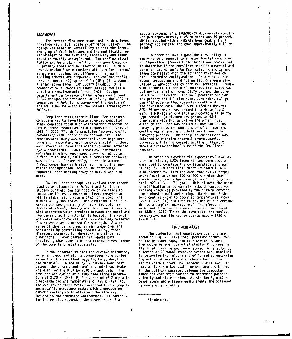
Combustors system composed of a BRUNSBOND* Hoskins-875 compli-ant pad approximately 0.25 cm thick and 35 percent
rhe reverse flow combustor used in this inves- dense, coupled with a NiCrAlY bond coat and a 8tigation was a full scale experimental design. The percenl YSZ ceramic top coat approximately 0.19 cmdesign was based on versatility so that the inter- thick.'changing of fuel injectors and the modification orreplacement of the swirlers, faceplate, and liner In order to investigate the feasibility ofcould be readily accomplished. The airflow distri- applying this concept to an experimental combustorbution and hole sizing of the liner were based on configuration, Brunswick Technetics was contracted36 primary holes and 36 dilution holes. In this to determine if the compliant metallic material andinvestigation four combustors with similar internal ceramic coating could be fabricated in a size andaerothermal design, but different liner wall shape consistent with the existing reverse-flowcooling schemes are compared. The cooling config- small combustor configuration. As a result, theurations were: (1) splash-film (SF); (2) a pseudo- actual combustion and dilution sections were sim-transpiration liner "LAMILLOY"* (TRANS); (3) a ulated by appropriate cylindrical sections. Bruns-counter-flow film-cooled liner (CFFC); and (4) a wick Technetics under NASA contract fabricated twocompliant metal/ceramic liner (CMC). Design cylindrical shells: one, 38.74 cm, and the otherdetails and performance of the referenced SF and 28.40 cm in diameter. The wall penetrations forTRANS designs are presented in Ref. 5, the CFFC is the primary and dilution hcles were identical 1opresented in Ref. 6. A summary of the design of the NASA reverse-flow combustor configuration.the CMC liner relevant to the present investigation The compliant metal shell was 0.1524 cm Hoskinsfollows. 875, 35 percent dense, brazed to a Hastelloy X
metal substrate on one side and coated with an YSZCompliant metal/ceramic liner. The research type ceramic (a mixture designated as GJ-1
objectve was to investigate advanced combustor propietary with Brunswick) on the other side.liner concepts capable of withstanding temperature Although the liner was coated in one continuousenvironments associated with temperature levels of spraying process the composition of the ceramic1922 K (3000 "F), while providing improved cyclic coating was altered about half way through thedurability with little or no coolant air. The spraying process. The change in composition wasexperimental study was performed under high pres- intended to minimize internal thermodynamicssure and temperature environments simulating those stresses within the ceramic coating. Figure 2encountered in combustors operating under advanced shows a cross-sectional view of the CMC linercycle conditions. Since structural parameters concept.relating to size, cujrvature, stresses, etc., aredifficult to scale, full scale combustor hardware In order to expedite the experimental evalua-was utilized. Consequently, to enable a more tion an existing NASA faceplate and turn sectiondirect comparison with metallic liners, the qeo- were used to complete the configuration as shownmetric configuration used in the previously in Fig. 3. In this first order approach it wasreported liner-cooling study of Ref. 6 was also also elected to limit the combustor outlet temper-used. ature level to values 200 to 400 K higher than
current practice rather than strive for the orig-The CMC liner concept was evolved from recent inal 1922 K (3000 'F) goal. This allowed the major
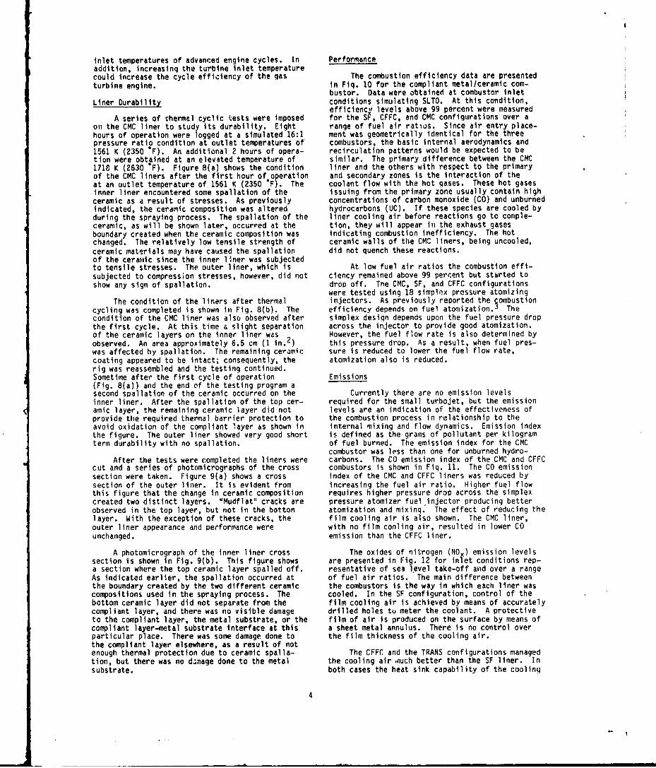
studies as discussed in Refs. 2 and 7. These simplification of using only backside convectivestudies outlined the application of ceramics to cooling which was provided by the passage betweencombustor liners by means of plasma spraying an the combustor wall and casing. Oxidation of theyttria stabilized zirconia (YSZ) on a compliant bond coat is known to occur at temperatures abovenickel alloy substrate. This compliant metal -ub- 1228 K (1750 "F) and lead to ýailure of the ceramicstrate was designed to yield at relatively low due to a complex interaction. Therefore, inlevels of stress, thereby absorbing the differen- order not to exceed the design temperature leveltial expansion which develops between the metal and of 1228 K (1750 OF) at the bond coat, the outletthe ceramic as the material is heated. The compli- temperature was limited to approximately 1789 Kant metal substrate was made from randomly oriented (2760 'F).fibers which are sintered for strength. A widerange of physical and mechanical properties are Instrumentationobtainable by controlling product alloy, fiberdiameter, porosity (or density), and sintering The combustor instrumentation stations areconditions. Fiber diameter influences both shown in Fig. 4. Five total pressure probes, twoinsulating characteristics and oxidation resistance static pressure taps, and four Chromel-Alumelof the compliant metal substrate, thermocouples are located at station 2 to measure
the inlet pressure and temperature. At station 3,In the reported studies the ceramic thickness, a series of 18 total p-essure probes are installed
material type, and yttria percentages were varied to determine the inlet-air profile and to determineas well as the compliant metallic type, density, the extent of any flow disturbance behind theand material. In the study- a NiCrAlY bond coat struts which support the centerbody diffuser. Atbetween the ceramic and compliant metal substrate station 4, six pitot-static probes are positionedwas used for the 8.64 by 9.90 cm test pads. The in the cold-air passages between the combustortest pad was cycled at a simulated flame tempera- liner and combustor housing to determine passageture of 2170 K (3445 *F) for a period of 2 min with velocity and distribution. At station 5, outleta backside coolant temperature of 493 K (427 "F). temperature and pressure measurements are obtainedThe results of these tests indicated that a compli- by means of a rotatingant metallic structure coated with a sprayed onceramic coating could withstand the stressesinduced in the combustor environment. In particu-lar the results suggested the superiority of a *Trademark.
2
probe. The probe contains three rakes spaced 120° (CMC) combustor 'liner was operated at conditionsapart, a five-position radial rake containing PT-PT typical of a 16:1 pressure ratio turbine engine.13 percent Rd thermocouples, a five-position total Liner temperature, combustion efficiency, andpressure rake, and a water cooled gas sampling exhaust emissiont are presented for simulatedrake. A 360" travel with sampling at 10" incre- flight conditions. Comparison with a counter-flowments was used for this program. film-cooled (CFFC) combustor, a conventional splash
film-cooled (SF) liner, and a simulated transpira-Procedure tion cooled (TRANS) combustor (Lamilloy) are also
included.Test Conditions
Liner TemperatureThe experimental rpverse flow combustor was
operated at test conditions based on a gas-turbine Liner wall tem erature. The liner temperatureengine cycle with a compressor pressure ratio of data a functi of W' air ratio for the sea16. A tabulation of the test conditions used in level take-off (SLTO) condition is shown in Fig. 6.this study is given in Table 1. The data presented are for two thermocouples
located on the surface of the inner and outer linerData were obtained at combustor inlet condi- 3.81 and 8.89 cm from the faceplate, respectively.
tions simulating sea level take-off (SLTO), and Both thermnrouples were positioned in-between ahigh altitude cruise. A series of thermal cycles different pair of nozzles. Each thermocouplewere run at conditions simulating SLTO to study the measurement represents the maximum temperaturesdurability of the CMC concept. Figure 5 shows the measured for each liner. The highest temperaturetest sequence followed and the amount of time that levels were measured on the inner liner with thethe combustor operated at the specified exit tem- maximum indication of 1122 K (1560 OF). The onlyperature. Each cycle consisted of a start, test cooling provided to the compliant metal/ceramiccondition set and shut-down. Starting was initi- liner was backside convection.ated at reduced temperature, pressure, and airflow.The system was then quickly set to the desired test Velocity probes located at station 4 (Fig. 4)conditions of pressure, temperature, air, and fuel measured air velocity and distribution in the cold-flow, and maintained for a selected period of time air passages between the combustor liners and theafter which the flame was extinguished. The com- combustor housing. Average air velocities of 20bustor was allowed to cool to ambient temperature and 40 m/s were measured for the inner and outerafter which the cycle was repeated. Simulated cold-air passages, respectively. The differenceflight data were obtained at fuel-air ratios up to in air velocity results in a reduction of the con-approximately 0.030. The simulated combustor test vective heat transfer for the inner liner. Inconditions were based on a reference velocity of addition, the heat flux within the combustor varies5.49 m/sec (18 ft/sec). The reference velocity due to the flame stabilization and combustion pro-quoted was based on unidirectional total mass flow cess. The resultant liner temperature is an indi-and the maximum cross-sectional area of the housing cation of the compliant layer ceramic interfaceprior to the reverse turn (Fig. 4). temperature. As previously mentioned an arbitrary
temperature level of 1228 K (1750 OF) was selectedThe test program was conducted using Jet-A as a goal to minimize oxidation of the bond inter-
fuel with 18 simplex pressure-atomizing fuel face between the compliant layer and the ceramic.injectors with a flow number of 4.8. Measured liner surface temperatures used to infer-
entially calculate interface temperatures indicatedEmission Measurements that this level was not exceeded.
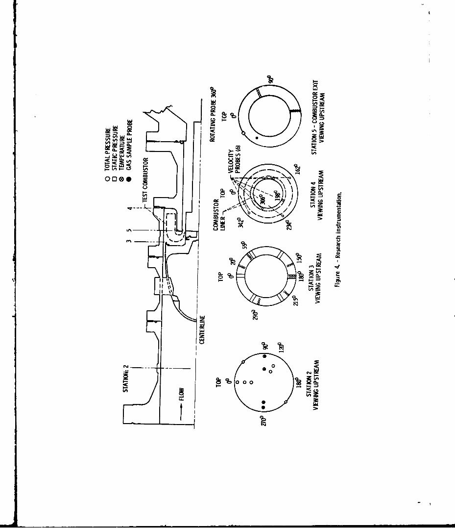
Exhaust gas samples were obtained according Liner cooling reduction. The reduction into the recommended procedures in Refs. 8 and 9. liner coolant for the LMC configuration is shownExhaust gases were withdrawn through the water in Fig. 7 and compared with the TRANS and CFFCcooled rotating probe mounted approximately in the configurations using as a reference the SF configu-stator plane and in the center of the exhaust duct ration. As shown, the CFFC and TRANS configura-at station 5 (Fig. 4). The gas sample temperature tions used from 40 to 50 percent less air than thewas held at approximately 423 K (302 *F) in the SF configuration and the liner temperatures wereelectrically heated sampling line. Most of the gas reduced by 12 percent. The CMC liner coolant flowsample entered the analyzer oven, while the excess was reduced by 80 percent and the liner temperaturesample was bypassed to the exhaust system. To was reduced by 13 percent (3.2 percent of the totalprevent fuel accumulation in the sample line, a air flow went through the annulus around the fuelnitrogen purge was used before and during combustor injectors and was considered as coolant flow).ignition. This comparison is for the cylindrical part of the
After passing through the analyzer oven the combustor liner since it is where the CMC was used.
gas sample was divided into three Darts, and each As shown, the TRANS, CFFC, arid CMC configura-part was analyzed. Concentrations of oxides of tions had similar reductions in liner temperature,nitrogen, carbon monoxide and carbon dioxide, and but the CMC liner provided exhaust temperatureshydrocarbons were measured by the chemiluminescence, 167 K (300 °F) hotter than current practice.nondispersed-infrared, and flame ionization methods, Although the CMC liner had similar reductions inrespectively. Details of the gas analysis system liner temperature compared to the advanced metallicare presented in Ref. 3. techniques, the most significant improvements are
the reduction of liner coolant flow and theResults and Discussion increase in turbine inlet temperature. The reduc-
tion of liner coolant flow frees air that can beA combustor featuring an advanced liner cool- used to increase the coolant flow to the turbine
ing technique known as the compliant metal/ceramic allowing the turbine operate at the higher turbine
3A"
inlet temperatures of advanced engine cycles. In Performanceaddition, increasinq the turbine inlet temperaturecould increase the cycle efficiency of the gas The combustion efficiency data are presentedturbine engine, in Fiq. 10 for the compliant metal/ceramic com-
bustor. Data were obtained at combustor inletLiner Durability conditions simulating SLTO. At this condition,
efficiency levels above g9 percent were measuredA series of thermal cyclic tests were imposed for the SF, CFFC, and CMC configurations over a
on the CMC liner to study its durability. Eight range of fuel air ratios. Since air entry place-hours of operation were logged at a simulated 16:1 ment was geometrically identical for the threepressure ratio condition at outlet temperatures of combustors, the basic internal aerodynamics and1561 K (2350 "F). An additional 2 hours of opera- recirculation patterns would be expected to betion were obtained at an elevated temperature of similar. The primary difference between the CMC1718 K (2630 *F). Figure 8(a) shows the condition liner and the others with respect to the primaryof the CMC liners after the first hour of operation and secondary zones is the interaction of theat an outlet temperature of 1561 K (2350 F). The coolant flow with the hot gases. These hot gasesinner liner encountered some spallation of the issuing from the primary zone usually contain highceramic as a result of stresses. As previously concentrations of carbon monoxide (CO) and unburnedindicated, the ceramic composition was altered hydrocarbons (UC). If these species are cooled byduring the spraying process. The spallation of the liner cooling air before reactions go to comple-ceramic, as will be shown later, occurred at the tion, they will appear in the exhaust gasesboundary created when the ceramic composition was indicating combustion inefficiency. The hotchanged. The relatively low tensile strength of ceramic walls of the CMC liners, being uncooled,ceramic materials may have caused the spallation did not quench these reactions.of the cerarmic since the inner liner was subjectedto tensile stresses. The outer liner, which is At low fuel air ratios the combustion effi-subjected to compression stresses, however, did not ciency remained above 99 percent but started toshow any sign of spallation. drop off. Toe CMC, SF, and CFFC configurations
were tested using 18 simplex pressure atomizingThe condition of the liners after thermal injectors. As previously reported the •ombustion
cycling was completed is shown in Fig. 8(b). The efficiency depends on fuel atomization.5 Thecondition of the CMC liner was also observed after simplex design depends upon the fuel pressure dropthe first cycle. At this time a slight separation across the injector to provide good atomization.of the ceramic layers on the inner liner was 2 However, the fuel flow rate is also determined byobserved. An area approximately 6.5 cm (1 in. 2 ) this pressure drop. As a result, when fuel pres-was affected by spallation. The remaining ceramic sure is reduced to lower the fuel flow rate,coating appeared to be intact; consequently, the atomization also is reduced.rig was reassembled and the testing continued.Sometime after the first cycle of operation Emissions(Fig. 8(a)) and the end of the testing program asecond spallation of the ceramic occurred on the Currently there are no emission levelsinner liner. After the spallation of the top cer- required for the small turbojet, but the emissionamic layer, the remaining ceramic layer did not levels are an indication of the effectiveness ofprovide the required thermal barrier protection to the combustion process in relationship to theavoid oxidation of the compliant layer as shown in internal mixing and flow dynamics. Emission indexthe figure. The outer liner showed very good short is defined as the grams of pollutant per kilogramterm durability with no spallation. of fuel burned. The emission index for the CMC
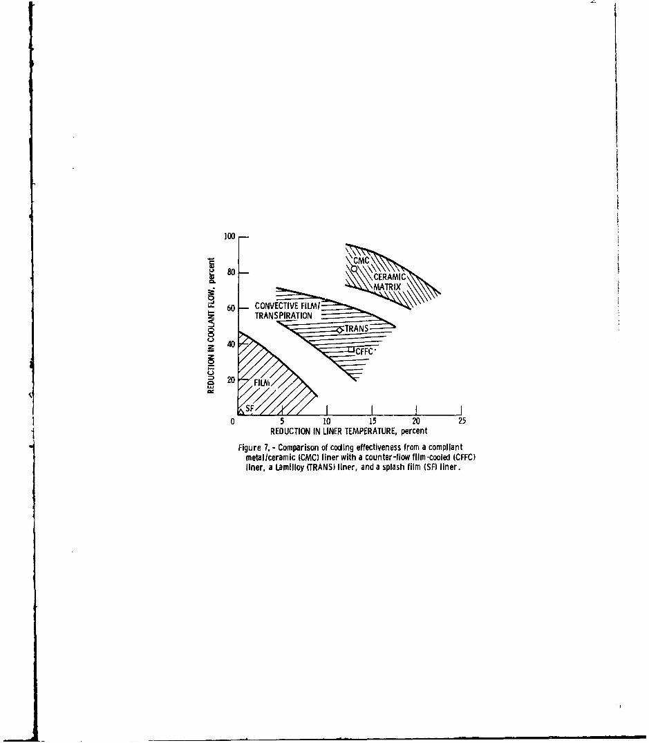
combustor was less than one for unburned hydro-After the tests were completed the liners were carbons. The CO emission index of the CMC and CFFC
cut and a series of photomicrographs of the cross combustors is shown in Fig. 11. The CO emissionsection were taken. Figure 9(a) shows a cross index of the CMC and CFFC liners was reduced bysection of the outer liner. It is evident from increasing the fuel air ratio. Higher fuel flowthis figure that the change in ceramic composition requires higher pressure drop across the simplexcreated two distinct layers. "Mudflat" cracks are pressure atomizer fuel injector producing betterobserved in the top layer, but not in the bottom atomization and mixing. The effect of reducing thelayer. With the exception of these cracks, the film cooling air is also shown. The CMC liner,outer liner appearance and performance were with no film cooling air, resulted in lower COunchanged. emission than the CFFC liner.
A photomicrograph of the inner liner cross The oxides of nitrogen (NO ) emission levelssection is shown in Fig. 9(b). This figure shows are presented in Fig. 12 for infet conditions rep-a section where the top ceramic layer spalled off. resentative of sea lgvel take-off and over a rangeAs indicated earlier, the spallation occurred at of fuel air ratios. The main difference betweenthe boundary created by the two different ceramic the combustors is the way in which each liner wascompositions used in the spraying process. The cooled. In the SF configuration, control of thebottom ceramic layer did not separate from the film cooling air is achieved by means of accuratelycompliant layer, and there was no visible damage drilled holes to meter the coolant. A protectiveto the compliant layer, the metal substrate, or the film of air is produced on the surface by means ofcompliant layer-metal substrate interface at this a sheet metal annulus. There is no control overparticular place. There was some damage done to the film thickness of the cooling air.the compliant layer elsewhere, as a result of notenough thermal protection due to ceramic spalla- The CFFC and the TRANS configurations managedtion, but there was no dzmage done to the metal the cooling air auch better than the SF liner. Insubstrate. both cases the heat sink capability of the cooling
4

air was used to transfer heat from the liner metal Concluding Remarksto the cooling air. Resulting in a better dis-tributed film at a much higher temperature than The experiments also indicated research areasthe SF configuration. The CMC configuration did for future compliant metal/ceramic development.not have film cooling air. Current efforts include: (1) grant studies of
internal heat transfer coefficients of the compli-The NO emission level for the CMC configu- ant layer, (2) contract studies aimed at evolving
ration was lower than tne SF configuration, but combustor design criteria, and (3) in-house experi-higher than the CFFC and TRANS configurations. The ments aimed at identifying and evaluating promisingCMC and TRANS liners have similar NOx emission concepts.trends with increasing fuel air ratio and both havea minimum interaction of the coolant with the com- A more significant increase in combustorbustion process. The stoichiometry, mixing, and outlet temperature could be obtained by incorporat-residence time would be expected to be similar yet ing some sort of cooling to the metal/ceramica higher NOx level was experienced with the CMC interface. Although the compliant layer helped toconfiguration. This increase in NOx can probably reduce some of the stresses, improved durabilitybe attributed to a hotter environment during the could be obtained for the inner liner by reducingperiod in which NOx is formed (i.e., the metallic the tensile stresses in the ceramic layer.counterpart operates at a lower wall temperaturewhich contributes to a higher heat flux rate). The application of fuel efficient, aggressiveThis hotter environment resulted in increased com- high temperature cycles to small gas turbine enginesbustion efficiency as noted in the CO measurement are within the realm of current advanced technologybut would also be conducive to increased NOx as demonstrated by the application compliantformation. The CFFC configuration produced the metal/ceramic concept to combustor liner design.lowest NOx level; however, in this case consider-able coolant is admitted in the primary zone which Referencesresulted in a reduction in overall stoichiometry(9 percent for the CFFC configuration as compared 1. Demetri, E.P., Topping, R.F., and Wilson, R.P.,to 3.2 percent for the CMC). Jr., "Study of Research and Development
Requirements of Small Gas-Turbine Combustors,"Summary of Results Arthur D. Little, Inc., Cambridge, MA,
ADL-83381-2, Jan. 1980. (NASA CR-159796)1. The use of the basic NASA reverse-flow
combustor design to accommodate a compliant metal/- 2. Venkat, R.S. and Roffe, G., "Testing of Felt-ceramic liner was successfully accomplished using Ceramic Materials for Combustor Applications,"existing design procedures and construction General Applied Science Labs., Inc., Westburry,techniques. NY, Apr. 1983. (NASA CR-168103)
2. The compliant metal/ceramic liner required 3. Norgren, C.T., and Riddlebaugh, S.M., "Effect80 percent less coolant, while the counter-flow of Fuel Injector Type on Performance and Emis-film-:ooled and the transpiration liners required sions of Reverse-Flow Combustor," NASA TP-1945,from 40 to 50 percent less coolant as compared to 1981.the refcrence splash film-cooled liner.
4. "Computer Program for the Analysis of Annular3. All three liners experienced almost the Combustors," Volume 1-Calculation Procedures,
same reduction in liner temperature, 12 to 13 per- Northern Research and Engineering Corp., Cam-cent, but the compliant metal/ceramic liner pro- bridge, MA, Report 1111-1, Vol. 1, Jan. 1968vided outlet temperatures 167 K (300 "F) hotter (NASA CR-72374).than current practice.
S5. Norqren, C.T., and Riddlebaugh, S.M.,"Small Gas4. The compliant metal/ceramic liner concept Turbine Combustor Study - Combustor Liner
resulted in an improvement not only with respect Evaluation," AIAA Paper 83-0337, Jan. 1983.to coolant and liner temperature reduction butalso in reduction of the nitrogen oxides (NOx) 6. Norgren, C.T., and Riddlebaugh, S.W., "Advancedemissions when compared with the splash Liner-Coolinq Techniques for Gas Turbine Com-film-cooled liner. bustors,h AIAA Paper 85-1290, July 1985.
5. Test results indicated that the outer liner 7. Ercegovic, D.B., Walker, C.L., and Norgren,exhibited very good short-term durability with no C.T., "Ceramic Composite Liner Material for Gasindication of spalling. The inner liner did Turbine Combustors," AIAA Paper 84-0363,encounter some spallation of the ceramic as a Jan. 1984.result of stresses within the coating itself.
8. "Control of Air Pollution from Aircraft Engines-6. The combustor was capable of providing Emission Standards and Test Procedures for Air-
higher exit temperatures than currently is possible craft," Federal Re ister, Volume 38, No. 136,with conventional cooling techniques. Yet, the Pt. 2, July 17, 1973, pp. 19088-19103.liner utilized noncritical, low cost materials, andonly convective cooling. 9. "Procedure for the Continuous Sampling and
Measurement of Gaseous Emissions from AircraftTurbine Engines," SAE ARP-1256A, Oct. 1980.
5

TABLE 1. - REVERSE-FLOW-COMBUSTOR TEST CONDITIONS
Test Total Inlet Inlet Referencea Simulated Commentscondi- airflow pressure temperature velocity compressortion pressure
kg/sec lb/sec kPa psia K * F m/sec ft/sec ratio
A 2.27 5 1014 147 686 775 5.5 18 10 High-altitude cruiseB 3.05 6.71 1358 197 703 805 5.5 i18 13.4 Low-altitude cruiseC. 3.63 8 1620 235 717 830 5.5 18 16 Sea level take-off (SLTO)D 1.23 2.70 405 58.5 474 394 5.2 16.9 4 Idle: f/a - 0.008E 2.12 4.66 862 125 627 668 5.5 18 8.5 Simulated reduced powerF 1.83 4.02 689 100 581 585 .. .---- 6.8G 1.51 3.33 517 75 526 486 --- ---- 5.1H 1.23 2.70 414 60 474 1394 --- I.---- 4.1
aParametric variation based on increase in mass flow to provide increases of 33 and 66 percent inreference velocity.

/C
iI~cm

HCJUSING-.%
METAL ANNULUS EXTERNALSUSRAECONVECTION FLOW THICKNESS MATERIALS
BRAZE-N //~ 0.0635cm HASTELLOYXCOMPLIANT Z' (HOS KINS 875LAYER '.- ~ ~ ,O 54m ALLOY WIRE
BOND - _ _ _ _ _ __35% DENSE-~ . -' . ~ YTCR IA
CEAI 0. 1525 cm STABILIZED
HOT SIDEFigure 2. -Cross section of the compliant metaliceramic liner concept.
(not to scale)
Figure 3. - Experimental combustor with compliant metal/ceramic liners.
uI-
:E I-
0000
\r6\~0 C
10-01>-
II"IC -e N
CC I- k
-- _ _ 0
0O CLJ
4-
Enz
(D >~
00
C6

OUTLET TEMPERATURE 1561 K (f a - 0. 024)120 J OUTLET TEMPERATURE 1718 K (fla- 0. 030)
80E
40
1 2 3 4 5 6 7 8 9 10 11LINER TEST SEQUENCE
Figure 5. - Liner durability test sequence. Inlet pressure, 1620 kPa(235 psia); inlet temperature. 717 K (830 OF); total airflow,3. 63 kglsec (8 Iblsec).
S1150 10a LI-NER
~1050 10
~950S'1200 AVERAGE EXIT AVERAGE EXIT
TEMPERATURE TEMPERATURE1561 K (2350 OF) 1718 K (2630 OF)
S1000.012 .016 .020 .024 .028 .032
FUEL AIR RATIO
Figure 6. - Comparison of liner wall temperatures for the compliant metal/ceramic liner. Inlet pressure, 1620 kPa (235 psia); Inlet temperature,717 K (830 OF); total airflow 3.63 kg/sec (8 Ib/sec).
100-
80
MA\TRIX
S60 CONVECTIVE FILM/STRANSPIRATION
z4 0
20
SFj0 5 10 15 20 25
REDUCTION IN LINER TEMPERATURE, percent
Figure 7. - Comparison of coding effectiveness from a compliantmetallceramic (CMC) liner with a counter-flow film-cooled (CFFC)liner, a Lamilloy (TRANS) liner, and a splash film (SF) liner.

0 --
.4- fJ
I--
I--
4-
C0 U
i,.W 0
I-
1=
I..
mm0)

BOTTOMLAYER7CERAMI CLAYERLAYER
ir CERAMIC
BOND
COOTTOAN
LLAYER
(a) Outer !lner, 50X. (IInrlnr OX
Figure 9. -Photomicrograph of liner cross sections.
~99.8
00~99.4 /NI
CFFC
S99.2
99.0 /.010 .014 .018 .022 .2FUEL-AIR RATIO02Figure 10. -Compliant metal/ceramic (CMC) combustor eff I-clency and comparison with splash-fim (SF) and counter-flow tlirn-coold (CFFC) configurations. inlet pressure,1620 kPa (235 psla); Inlet temperature, 7i7 K (830 OF); totalairflow, 3.63 kglsec: (8 Ib/sec).
LINER0 CA4C
SCFFC
2
.010 .014 .018 .2 06 .FUEL AIR RATIO .3Figure 11. - Comparison of carbon monoxide emission from a compliantmetal/ceramic (CMC liner with a counter-flow film -cooled (CFFC)liner, Inlet pressure, 1620 kPa (235 psla); Inlet temperature, 717 K(830 oF); total airtlow, 3.63 kg/sec (8 ib/sec).
LINER0 CMC
--- S
20- TRANSCFFC
-Zll
.012 ..014 .01_6 .018 .020 ~ .022.02 4 .026FUEL AIR RiATIO.04 02Figure 12 Comparison Of oxides of nitrogen emission from acompliant metaliceramic (CMC) liner with a counter-flow film-cooled (CFFCJ liner. a Lamin~oy (TRANS) liner, and a splashfilm (SF) liner. Inlet pressure, 1620 kPa (235 psia); Inlet
temperature, 717 K (830 OF); total airflow, 3.63 kg/sec (8 WbSW.j
1. Report No. NASA TM-87304 3C
USAAVSCOM- TR-86..-.-ReitC atlg o4. Title and Suhtille 5. RePort Date
Small Gas Turbine Combustor Experimental Study -Compliant Metal/Ceramic Liner and Performance 6. Performing Organization Code
Evaluation 535.05- 017. Author(s) 8. Performing Organization Report No.
Waldo A. Acosta and Carl T. Norgren E-301610. Work Unit No.
9. Performing Organization Name and Addresa11. Contract or Grant No.
National Aeronautics and Space AdministrationLewis Research CenterCleveland, Ohio 44135 13. Type of Report and Period Covered
12. Sponsoring Agency Name and Address Technical Memorandum
National Aeronautics and Space Administration 14. Sponsoring Agency Code
Washington, D.C. 20546
15. Supplementary Notes
Waldo A. Acosta, Propulsion Directorate, U.S. Army Aviation Research andTechnology Activity - AVSCON; Carl T. Norgren, NASA Lewis Research Center.Prepared for the 22nd Joint Propulsion Conference, cosponsored by the AIAA,ASME, SAE, and ASEE, Huntsville, Alabama, June 16-18, 1986.
16. Abstract
P.Combustor research relating to the development of fuel efficient small gas tur-bine engines capable of meeting future commercial and military aviation needs iscurrently underway at NASA Lewis. As part of this combustor research, a basicreverse-flow combustor has been used to investigate advanced liner wall coolingtechniques. Liner temperature, performance, and exhaust emissions of the experi-mental combustor utilizing compliant metal/ceramic liners were determined andcompared with three previously reported combustors that featured: (1) splashfilm-cooled liner walls; (2) transpiration cooled liner walls; and (3) counter-flow film cooled panels. -.4
17. Key Words (Suggested by Author(s)) 18. Distribution Statement
Gas turbine combustor; Liner cooling; Unclassified - unlimitedCompliant layer; Ceramic combustor; STAR Category 07Ceramic liner
19. Security Claself. (of this report) 20. Security Clasalf. (of this page) 21. No. of pageg 22. Price*
Unclassified IUnclassified 5T*For sale by the National Technical Information Service, Springfield, Virginia 22161