Small-diameter Proximity Sensor - assets.omron.com · 1 Small-diameter Proximity Sensor E2E Ultra...
18
1 Small-diameter Proximity Sensor E2E Ultra small size and simple to install! • With the addition of M4, 5.4-dia., 6.5-dia. size, unshielded, pre-wired connector model, and connector model, a total of 108 model variations are available. • High-speed response frequency stably detects moving objects: 5 kHz max. • Four indicator LEDs for easier indicator positioning. • Special mounting brackets reduce time and efforts for installation. • Stainless-steel Spiral Tube protects against wire breakage is available (M4, M5 only). • Models also available with standard cables that are 5 m long or with robot (bending-resistant) cables. Features Lineup of global small-diameter types (3 dia., 4 dia., 5.4 dia., 6.5 dia., M4, M5) • A lineup of unshielded models for long distance sensing is also available. Stable long distance sensing performance enables worry-free use even when the work flow is unsteady. Bright operation indicators make it easy to view operation status • Four indicator LEDs in a 360 degree layout can be easily seen. High-speed response enables sharp detection timing • 5 kHz response frequency max. Protection circuits prevent failures due to wiring mistakes. • Load short-circuit protection and output reverse polarity protection circuits are incorporated. Low current consumption: 10 mA max. • Current consumption is 2/3 that of conventional small diameter proximity sensors. Protective Stainless-steel Spiral Tubes available • Lineup of protective tubes for M4 and M5 sizes. Reduces wire breakage due to catching and shock. For the most recent information on models that have been certified for safety standards, refer to your OMRON website. Refer to Safety Precautions on page 10.
Transcript of Small-diameter Proximity Sensor - assets.omron.com · 1 Small-diameter Proximity Sensor E2E Ultra...

1
Small-diameter Proximity SensorE2E
Ultra small size and simple to install!
• With the addition of M4, 5.4-dia., 6.5-dia. size, unshielded,pre-wired connector model, and connector model, a total of108 model variations are available.
• High-speed response frequency stably detects movingobjects: 5 kHz max.
• Four indicator LEDs for easier indicator positioning.• Special mounting brackets reduce time and efforts for
installation.• Stainless-steel Spiral Tube protects against wire
breakage is available (M4, M5 only).• Models also available with standard cables that are 5 m long
or with robot (bending-resistant) cables.
FeaturesLineup of global small-diameter types (3 dia., 4 dia., 5.4 dia., 6.5 dia., M4, M5)• A lineup of unshielded models for long distance sensing is also available. Stable long distance sensing performance enables worry-free use
even when the work flow is unsteady.
Bright operation indicators make it easy to view operation status• Four indicator LEDs in a 360 degree layout can be easily seen.
High-speed response enables sharp detection timing• 5 kHz response frequency max.
Protection circuits prevent failures due to wiring mistakes.• Load short-circuit protection and output reverse polarity protection
circuits are incorporated.
Low current consumption: 10 mA max.• Current consumption is 2/3 that of conventional small diameter
proximity sensors.
Protective Stainless-steel Spiral Tubes available• Lineup of protective tubes for M4 and M5 sizes. Reduces wire
breakage due to catching and shock.
For the most recent information on models that have been certified for safety standards, refer to your OMRON website.Refer to Safety Precautions on page 10.

E2E
2
E2E (Small Diameter) Model Number Legend
Note: The purpose of this model number legend is to provide understanding of the meaning of specifications from the model number.Models are not available for all combinations of code numbers.
No. Classification Code Meaning
A Case material and shapeC Cylindrical
S SUS, threaded
B Size
03 Outer diameter 3 mm
04 Outer diameter 4 mm
05 Threaded: Outer diameter 5 mm, Cylindrical: Outer diameter 5.4 mm
06 Outer diameter 6.5 mm
C ShieldingS Shielded Models
N Unshielded Models
D Sensing distance Number R8: 0.8 mm, 01: 1 mm, 12: 1.2 mm, 02: 2 mm, 03: 3 mm, 04: 4 mm
E Connecting method
WC PVC Pre-wired Model
MC M8 Connector, 3-pin
CJ M8 Pre-wired Connector, 3-pin
F Output specificationsB DC 3-wire PNP open-collector output
C DC 3-wire NPN open-collector output
G Operation mode1 Normally open (NO)
2 Normally closed (NC)
H Cable specificationsBlank Standard PVC cable
R Robot (bending-resistant) PVC cable
I Cable lengthBlank Connector Models
Number M Cable length (Unit: m)(Applicable to Pre-wired Models 2M/5M and Pre-wired Connector Models 0.3M)
E2E- A B C D E F G H I- - -

E2E
3
Ordering InformationSensorsShielded Models [Refer to Dimensions on page 12.]
*1. Models with 5-m cable length are also available with "5M" suffix. (Example: E2E-C04S12-WC-C1 5M)*2. Models with robot (bending-resistant) cable are also available with "-R" in the model number. (Example: E2E-C04S12-WC-C1-R 2M)*3. Models with 5-m robot (bending-resistant) cable are also available with "-R" and the "5M" suffix in the model number. (Example: E2E-C04S12-
WC-C1-R 5M)
Appear-ance
Sensing distance
Connecting method
Cable specifications
Operation mode
Wire color / pin arrangement
Model
NPN output PNP output
3 dia.
Pre-wired Models (2 m)
PVC (oil-resistant)
NO Brown: +VBlack: OutputBlue: 0 V
E2E-C03SR8-WC-C1 2M *1 E2E-C03SR8-WC-B1 2M *1
NC E2E-C03SR8-WC-C2 2M *1 E2E-C03SR8-WC-B2 2M *1
M8 Pre-wired Connector Models (0.3 m)
PVC (oil-resistant)
NO 1: +V, 3: 0 V, 4: Control output
E2E-C03SR8-CJ-C1 0.3M E2E-C03SR8-CJ-B1 0.3M
NC E2E-C03SR8-CJ-C2 0.3M E2E-C03SR8-CJ-B2 0.3M
4 dia.
Pre-wired Models (2 m)
PVC (oil-resistant)
NO Brown: +VBlack: OutputBlue: 0 V
E2E-C04S12-WC-C1 2M *1 *2 *3 E2E-C04S12-WC-B1 2M *1 *2 *3
NC E2E-C04S12-WC-C2 2M *1 *2 *3 E2E-C04S12-WC-B2 2M *1 *2 *3
M8 Pre-wired Connector Models (0.3 m)
PVC (oil-resistant)
NO
1: +V, 3: 0 V, 4: Control output
E2E-C04S12-CJ-C1 0.3M E2E-C04S12-CJ-B1 0.3M
NC E2E-C04S12-CJ-C2 0.3M E2E-C04S12-CJ-B2 0.3M
M8 Connector Models ---
NO E2E-C04S12-MC-C1 E2E-C04S12-MC-B1
NC E2E-C04S12-MC-C2 E2E-C04S12-MC-B2
5.4 dia. Pre-wired Models (2 m)
PVC (oil-resistant)
NO Brown: +VBlack: OutputBlue: 0 V
E2E-C05S01-WC-C1 2M *1 *2 *3 E2E-C05S01-WC-B1 2M *1 *2 *3
NC E2E-C05S01-WC-C2 2M *1 *2 E2E-C05S01-WC-B2 2M *1 *2
6.5 dia.
Pre-wired Models (2 m)
PVC (oil-resistant)
NO Brown: +VBlack: OutputBlue: 0 V
E2E-C06S02-WC-C1 2M *1 *2 *3 E2E-C06S02-WC-B1 2M *1 *2 *3
NC E2E-C06S02-WC-C2 2M *1 *2 *3 E2E-C06S02-WC-B2 2M *1 *2 *3
M8 Pre-wired Connector Models (0.3 m)
PVC (oil-resistant)
NO
1: +V, 3: 0 V, 4: Control output
E2E-C06S02-CJ-C1 0.3M E2E-C06S02-CJ-B1 0.3M
NC E2E-C06S02-CJ-C2 0.3M E2E-C06S02-CJ-B2 0.3M
M8 Connector Models ---
NO E2E-C06S02-MC-C1 E2E-C06S02-MC-B1
NC E2E-C06S02-MC-C2 E2E-C06S02-MC-B2
M4
Pre-wired Models (2 m)
PVC (oil-resistant)
NO Brown: +VBlack: OutputBlue: 0 V
E2E-S04SR8-WC-C1 2M *1 E2E-S04SR8-WC-B1 2M *1
NC E2E-S04SR8-WC-C2 2M *1 E2E-S04SR8-WC-B2 2M *1
M8 Pre-wired Connector Models (0.3 m)
PVC (oil-resistant)
NO 1: +V, 3: 0 V, 4: Control output
E2E-S04SR8-CJ-C1 0.3M E2E-S04SR8-CJ-B1 0.3M
NC E2E-S04SR8-CJ-C2 0.3M E2E-S04SR8-CJ-B2 0.3M
M5
Pre-wired Models (2 m)
PVC (oil-resistant)
NO Brown: +VBlack: OutputBlue: 0 V
E2E-S05S12-WC-C1 2M *1 *2 *3 E2E-S05S12-WC-B1 2M *1 *2 *3
NC E2E-S05S12-WC-C2 2M *1 *2 *3 E2E-S05S12-WC-B2 2M *1 *2 *3
M8 Pre-wired Connector Models (0.3 m)
PVC (oil-resistant)
NO
1: +V, 3: 0 V, 4: Control output
E2E-S05S12-CJ-C1 0.3M E2E-S05S12-CJ-B1 0.3M
NC E2E-S05S12-CJ-C2 0.3M E2E-S05S12-CJ-B2 0.3M
M8 Connector Models ---
NO E2E-S05S12-MC-C1 E2E-S05S12-MC-B1
NC E2E-S05S12-MC-C2 E2E-S05S12-MC-B2
0.8 mm
1.2 mm
1 mm
2 mm
0.8 mm
1.2 mm

E2E
4
Unshielded Models [Refer to Dimensions on page 13.]
*1. Models with 5-m cable length are also available with "5M" suffix. (Example: E2E-C04N03-WC-C1 5M)*2. Models with robot (bending-resistant) cable are also available with "-R" in the model number. (Example: E2E-C04N03-WC-C1-R 2M)
Appear-ance
Sensing distance
Connecting method
Cable specifications
Operation mode
Wire color / pin arrangement
Model
NPN output PNP output
3 dia.
Pre-wired Models (2 m)
PVC (oil-resistant)
NO Brown: +VBlack: OutputBlue: 0 V
E2E-C03N02-WC-C1 2M *1 E2E-C03N02-WC-B1 2M *1
NC E2E-C03N02-WC-C2 2M *1 E2E-C03N02-WC-B2 2M *1
M8 Pre-wired Connector Models (0.3 m)
PVC (oil-resistant)
NO 1: +V, 3: 0 V, 4: Control output
E2E-C03N02-CJ-C1 0.3M E2E-C03N02-CJ-B1 0.3M
NC E2E-C03N02-CJ-C2 0.3M E2E-C03N02-CJ-B2 0.3M
4 dia.
Pre-wired Models (2 m)
PVC (oil-resistant)
NO Brown: +VBlack: OutputBlue: 0 V
E2E-C04N03-WC-C1 2M *1 *2 E2E-C04N03-WC-B1 2M *1 *2
NC E2E-C04N03-WC-C2 2M *1 *2 E2E-C04N03-WC-B2 2M *1 *2
M8 Pre-wired Connector Models (0.3 m)
PVC (oil-resistant)
NO
1: +V, 3: 0 V, 4: Control output
E2E-C04N03-CJ-C1 0.3M E2E-C04N03-CJ-B1 0.3M
NC E2E-C04N03-CJ-C2 0.3M E2E-C04N03-CJ-B2 0.3M
M8 Connector Models ---
NO E2E-C04N03-MC-C1 E2E-C04N03-MC-B1
NC E2E-C04N03-MC-C2 E2E-C04N03-MC-B2
6.5 dia.
Pre-wired Models (2 m)
PVC (oil-resistant)
NO Brown: +VBlack: OutputBlue: 0 V
E2E-C06N04-WC-C1 2M *1 *2 E2E-C06N04-WC-B1 2M *1 *2
NC E2E-C06N04-WC-C2 2M *1 *2 E2E-C06N04-WC-B2 2M *1 *2
M8 Pre-wired Connector Models (0.3 m)
PVC (oil-resistant)
NO
1: +V, 3: 0 V, 4: Control output
E2E-C06N04-CJ-C1 0.3M E2E-C06N04-CJ-B1 0.3M
NC E2E-C06N04-CJ-C2 0.3M E2E-C06N04-CJ-B2 0.3M
M8 Connector Models ---
NO E2E-C06N04-MC-C1 E2E-C06N04-MC-B1
NC E2E-C06N04-MC-C2 E2E-C06N04-MC-B2
M4
Pre-wired Models (2 m)
PVC (oil-resistant)
NO Brown: +VBlack: OutputBlue: 0 V
E2E-S04N02-WC-C1 2M *1 E2E-S04N02-WC-B1 2M *1
NC E2E-S04N02-WC-C2 2M *1 E2E-S04N02-WC-B2 2M *1
M8 Pre-wired Connector Models (0.3 m)
PVC (oil-resistant)
NO 1: +V, 3: 0 V, 4: Control output
E2E-S04N02-CJ-C1 0.3M E2E-S04N02-CJ-B1 0.3M
NC E2E-S04N02-CJ-C2 0.3M E2E-S04N02-CJ-B2 0.3M
M5
Pre-wired Models (2 m)
PVC (oil-resistant)
NO Brown: +VBlack: OutputBlue: 0 V
E2E-S05N03-WC-C1 2M *1 *2 E2E-S05N03-WC-B1 2M *1 *2
NC E2E-S05N03-WC-C2 2M *1 *2 E2E-S05N03-WC-B2 2M *1 *2
M8 Pre-wired Connector Models (0.3 m)
PVC (oil-resistant)
NO
1: +V, 3: 0 V, 4: Control output
E2E-S05N03-CJ-C1 0.3M E2E-S05N03-CJ-B1 0.3M
NC E2E-S05N03-CJ-C2 0.3M E2E-S05N03-CJ-B2 0.3M
M8 Connector Models ---
NO E2E-S05N03-MC-C1 E2E-S05N03-MC-B1
NC E2E-S05N03-MC-C2 E2E-S05N03-MC-B2
2 mm
3 mm
4 mm
2 mm
3 mm

E2E
5
Accessories (Sold separately)Sensor I/O Connector (Socket on One Cable End)A Sensor I/O Connector is not provided with the Sensor. It must be ordered separately as required. [Refer to Dimensions on page 16.]
Mounting BracketsA Mounting Bracket is not provided with the Sensor. It must be ordered separately as required. [Refer to Dimensions on page 15.]
Nut SetA Nut Set is included with the Sensor. Order a Nut Set when required, e.g., if you lose the nuts.
Protective Stainless-steel Spiral Tube against Wire BreakageA Spiral Tube is not provided with the Sensor. It must be ordered separately as required. [Refer to Dimensions on page 16.]
Size Cable specifications
Number of cable wires (conductors) Cable length L (m)
Straight Right-angle
Model
M8 Robot (bending-resistant) cable 3
2 XS3F-M321-302-R XS3F-M322-302-R
5 XS3F-M321-305-R XS3F-M322-305-R
Applicable Sensors Appearance Model Quantity Remarks
E2E-C03@ Y92E-SC03 1 Mounting block for 3 dia., M3-20 Hexagon socket head cap screws: 2pieces, M3 × P0.5 Hexagon nuts: 2pieces, Washers: 2pieces
E2E-C04@ Y92E-SC04 1 Mounting block for 4 dia., M3-20 Hexagon socket head cap screws: 2pieces, M3 × P0.5 Hexagon nuts: 2pieces, Washers: 2pieces
E2E-C05@ Y92E-SC05 1 Mounting block for 5.4 dia., M3-20 Hexagon socket head cap screws: 2 pieces, M3 × P0.5 Hexagon nuts: 2 pieces, Washers: 2 pieces
E2E-C06@ Y92E-SC06 1 Mounting block for 6.5 dia., M3-20 Hexagon socket head cap screws: 2pieces, M3 × P0.5 Hexagon nuts: 2pieces, Washers: 2pieces
E2E-S04@ Y92E-SS04 1 L-shaped Mounting Bracket for M4 screws
E2E-S05@ Y92E-SS05 1 L-shaped Mounting Bracket for M5 screws
Applicable Sensors Model Applicable sensor outer diameter Set contents
E2E-S04@ Y92E-NWS04 M4Clamping nuts: 2 pieces, toothed washer: 1 piece
E2E-S05@ Y92E-NWS05 M5
Applicable Sensors Model Applicable sensor outer diameter Length
E2E-S04@Y92E-STS04-05
M40.5 m
Y92E-STS04-10 1 m
E2E-S05@Y92E-STS05-05
M50.5 m
Y92E-STS05-10 1 m

E2E
6
Ratings and Specifications
*1. Using within the set distance enables high-speed responsiveness and a more stable repeat accuracy.*2. The response frequency is an average value.*3. When used at a power of 12 V, the Sensor is less susceptible to the effects of internal self heat generation and therefore a more stable repeat accuracy can be
obtained.*4. When the control output is 20 mA or less, the Sensor is less susceptible to the effects of internal self heat generation and therefore a more stable repeat accuracy can be
obtained. *5. 3 dia., M4: load current 50 mA, cable length 2 m
4 dia., 5.4 dia., M5: load current 100 mA, cable length 2 m6.5 dia.: load current 200 mA, cord length 2 m
*6. Oil resistance in-house standard: Performance with respect to water insoluble oil. (Test at right)
*7. Material name in EN standards.*8. Clamping nuts: 2 pieces, toothed washer: 1 piece
Size 3 dia. 4 dia. 5.4 dia. 6.5 dia. M4 M5Type Shielded Unshielded Shielded Unshielded Shielded Shielded Unshielded Shielded Unshielded Shielded Unshielded
Item Model E2E-C03SR8@
E2E-C03N02@
E2E-C04S12@
E2E-C04N03@
E2E-C05S01@
E2E-C06S02@
E2E-C06N04@
E2E-S04SR8@
E2E-S04N02@
E2E-S05S12@
E2E-S05N03@
Sensing distance(at 23°C)
0.8 mm ±10%
2 mm ±10%
1.2 mm ±10%
3 mm ±10%
1mm±10%
2 mm ±10%
4 mm ±10%
0.8 mm ±10%
2 mm ±10%
1.2 mm ±10%
3 mm ±10%
Setting distance *1(Sensing distance × 0.7)
0 to 0.56 mm
0 to 1.4 mm
0 to 0.84 mm
0 to 2.1 mm
0 to 0.7 mm
0 to 1.4 mm
0 to 2.8 mm
0 to 0.56 mm
0 to 1.4 mm
0 to 0.84 mm
0 to 2.1 mm
Differential travel 15% max. of sensing distanceDetectable object Ferrous metal (The sensing distance decreases with non-ferrous metal. Refer to Engineering Data on page 7.) Standard sensing object
Iron, 3 × 3 × 1 mm
Iron, 6 × 6 × 1 mm
Iron, 4 × 4 × 1 mm
Iron, 9 × 9 × 1 mm
Iron, 5.4 × 5.4 × 1 mm
Iron, 6.5 × 6.5 × 1 mm
Iron, 12 × 12 × 1 mm
Iron, 3 × 3 × 1 mm
Iron, 6 × 6 × 1 mm
Iron, 4 × 4 × 1 mm
Iron, 9 × 9 × 1 mm
Response frequency *2 5 kHz 3.5 kHz 4 kHz 2 kHz 4 kHz 3 kHz 3 kHz 5 kHz 3.5 kHz 4 kHz 2 kHzPower supply voltage *3 10 to 30 VDC (including 10% ripple (p-p))Current consumption 10 mA max.
Control output *4
Load current 50 mA max. 100 mA max.200 mA max. (60 to 70°C: 100 mA)
50 mA max. 100 mA max.
Residual voltage 2 V max. *5
Indicators Operation indicator: Yellow (complies with European standard EN60947-5-2) Lights during output.
Operation mode B1/B2: PNP open collector, C1/C2: NPN open collectorB1/C1 models: NO, B2/C2 models: NC
Protection circuits Output reverse polarity protection, Power source circuit reverse polarity protection, Surge suppressor, Load short-circuit protectionAmbient temperature range Operation and storage: −25 to 70°C (with no icing or condensation)
Ambient humidity range Operation and storage: 35% to 95% (with no condensation)
Temperature influence ±15% max. of sensing distance at 23°C within temperature range of −25 to 70°C
Voltage influence ±2.5% max. of sensing distance at rated voltage in the rated voltage ±15% rangeInsulation resistance 50 MΩ min. (at 500 VDC) between current-carrying parts and caseDielectric strength 500 VAC, 50/60 Hz for 1 minute between current-carrying parts and caseVibration resistance Destruction: 10 to 55 Hz, 1.5-mm double amplitude for 2 hours each in X, Y, and Z directionsShock resistance Destruction: 500 m/s2 10 times each in X, Y, and Z directionsDegree of protection IEC 60529 IP67, in-house standards: oil-resistant *6
Con-necting method
Pre-wired Models Yes Yes Yes Yes Yes Yes
M8 Pre-wired Connector Models
Yes Yes No Yes Yes Yes
M8 Connector Models No Yes No Yes No Yes
Weight(packedstate)
Pre-wired Models
Approx. 25 g
Approx. 30 g
Approx. 35 g
Approx. 35 g
Approx. 35 g
Approx. 55 g
Approx. 55 g
Approx. 30 g
Approx. 30 g
Approx. 35 g
Approx. 40 g
M8 Pre-wired Connector Models
Approx. 20 g
Approx. 20 g
Approx. 15 g
Approx. 20 g --- Approx.
20 gApprox. 25 g
Approx. 20 g
Approx. 20 g
Approx. 20 g
Approx. 20 g
M8 Connector Models --- --- Approx.
10 gApprox. 10 g --- Approx.
10 gApprox. 15 g --- ---
Approx. 15 g
Approx. 15 g
Materi-als
Case SUS303 (EN 1.4305) *7Nickel-plated brass
SUS303 (EN 1.4305) *7
Sensing surface Heat-resistant ABS
Clamping nuts *8 No SUS430 (EN 1.4016) *7
Toothed washer *8 No SUS303 (EN 1.4305) *7
Cable Polyvinyl chloride (PVC)
Acces-sories
Instruction manual Yes
Model label YesMounting brackets Sold separately
Oil resistance testAfter the test time elapses, the characteristics below are checked for problems.(1) Visual appearance (no damage that
affects product characteristics)(2) Operation check (ON/OFF)(3) Insulation resistance (50 MΩ min. at
500 VDC)(4) Dielectric strength (500 VAC, 1 min.)(5) Water resistance (IP67)
Test oil: Water insoluble oil Velocite No. 3
(manufactured by Exxon Mobil)
50°C × 250 hoursDepth 10 cm
Sensor

E2E
7
Engineering Data (Reference Value)Sensing Area
Influence of Sensing Object Size and Material
Shielded ModelsE2E-C/S@S@
Unshielded ModelsE2E-C/S@N@
Note: The workpiece is a standard sensing object.For details, refer to Ratings and Specifications on page 6.
Shielded ModelsE2E-C03SR8@/E2E-S04SR8@ E2E-C04S12@/E2E-S05S12@ E2E-C05S01@
E2E-C06S02@
Unshielded ModelsE2E-C03N02@/E2E-S04N02@ E2E-C04N03@/E2E-S05N03@ E2E-C06N04@
Distance Y (mm)
Dis
tanc
e X
(m
m)
XY
2.5
2
1.5
1
0.5
0-8 -6 -4 -2 0 2 4 6 8
E2E-C05S01@
E2E-C03SR8@E2E-S04SR8@
E2E-C06S02@
E2E-C04S12@E2E-S05S12@
XY
4.5
4
3.5
3
2.5
2
1.5
1
0.5
0-10 -5 0 5 10
Distance Y (mm)
E2E-C06N04@
E2E-C03N02@E2E-S04N02@
E2E-C04N03@E2E-S05N03@
Dis
tanc
e X
(m
m)
0.9
0.8
0.7
0.6
0.5
0.4
0.3
0.2
0.1
0 5 10 15 20 25 30 35
Side length of sensing object: d (mm)
Stainless steel (SUS304)
Iron
Brass
Aluminum
Copper
Dis
tanc
e X
(m
m)
@d t = 1 mmX
1.6
1.4
1.2
1.0
0.8
0.6
0.4
0.2
Dis
tanc
e X
(m
m)
Side length of sensing object: d (mm)
Iron
Stainless steel (SUS304)
Brass
Aluminum
Copper
0 5 10 15 20 25 30 35
@d t = 1 mmX
1.6
1.4
1.2
1.0
0.8
0.6
0.4
0.2
0 5 10 15 20 25 30 35
Dis
tanc
e X
(m
m)
Side length of sensing object: d (mm)
IronStainless steel (SUS304)
Brass
Aluminum
Copper
@d t = 1 mmX
2.5
2
1.5
1
0.5
Dis
tanc
e X
(m
m)
0 5 10 15 20 25 30 35
Side length of sensing object: d (mm)
Iron
Stainless steel (SUS304)
Brass
Aluminum
Copper
@d t = 1 mmX
2.5
2
1.5
1
0.5
Dis
tanc
e X
(m
m)
0 5 10 15 20 25 30 35
Side length of sensing object: d (mm)
Iron
Stainless steel (SUS304)
Brass
Aluminum
Copper
@d t = 1 mmX
3.5
3
2.5
2
1.5
1
0.5
Dis
tanc
e X
(m
m)
0 5 10 15 20 25 30 35
Side length of sensing object: d (mm)
Iron
Stainless steel (SUS304)
Brass
Aluminum
Copper
@d t = 1 mmX
5
4
3
2
1
Dis
tanc
e X
(m
m)
Side length of sensing object: d (mm)
0 5 10 15 20 25 30 35
Iron
Stainless steel (SUS304)
Brass
Aluminum
Copper
@d t = 1 mmX

E2E
8
Distance - Horizontal Repeat Accuracy
Sensing distance vs. repeat accuracy graphsBy using within the sensor installation distance, the repeat accuracy stabilizes.This data is reference data based on a standard sensing object, and is not a guarantee of performance.The repeat accuracy varies depending on the effects of temperature, the material and surface condition of the sensing object, and other conditions.
Minimum measurement gap
Note: Measured at constant temperature of 23ºC using an iron sensing object of size at least as large as standard sensing object (see right).
Shielded ModelsE2E-C03SR8@/E2E-S04SR8@ E2E-C04S12@/E2E-S05S12@ E2E-C05S01@
E2E-C06S02@
Unshielded ModelsE2E-C03N02@/E2E-S04N02@ E2E-C04N03@/E2E-S05N03@ E2E-C06N04@
Model Minimum gap (mm)
E2E-C03S/S04S 0.3
E2E-C03N/S04N 0.6
E2E-C04S/S05S 0.4
E2E-C04N/S05N 0.9
E2E-C05S 0.3
E2E-C06S 0.6
E2E-C06N 1.2
0.8
0.7
0.6
0.5
0.4
0.3
0.2
0.1
0 0.05 0.1 0.15 0.2
Repeat accuracy (mm)
12 VDC
24 VDC
Dis
tanc
e X
(m
m)
ON point repeat accuracy
@3 × 1 mm
X
1.2
1
0.8
0.6
0.4
0.2
0 0.05 0.1 0.15 0.2
12 VDC
24 VDC
Dis
tanc
e X
(m
m)
Repeat accuracy (mm)
ON point repeat accuracy
@4 × 1 mm
X
1.2
1
0.8
0.6
0.4
0.2
0 0.05 0.1 0.15 0.2
X
12 VDC24 VDC
Dis
tanc
e X
(m
m)
ON point repeat accuracy
@5.4 × 1 mm
Repeat accuracy (mm)
2
1.8
1.6
1.4
1.2
1
0.8
0.6
0.4
0.2
0 0.05 0.1 0.15 0.2
12 VDC 24 VDC
Dis
tanc
e X
(m
m)
Repeat accuracy (mm)
ON point repeat accuracy
@6.5 × 1 mm
X
2
1.8
1.6
1.4
1.2
1
0.8
0.6
0.4
0.2
0 0.1 0.2 0.3 0.4 0.5
12 VDC 24 VDC
Dis
tanc
e X
(m
m)
Repeat accuracy (mm)
ON point repeat accuracy
@6 × 1 mm
X
3
2.5
2
1.5
1
0.5
0 0.1 0.2 0.3 0.4 0.5
12 VDC 24 VDC
Dis
tanc
e X
(m
m)
Repeat accuracy (mm)
ON point repeat accuracy
@9 × 1 mm
X
4
3.5
3
2.5
2
1.5
1
0.5
0 0.1 0.2 0.3 0.4 0.5
12 VDC 24 VDC
Dis
tanc
e X
(m
m)
Repeat accuracy (mm)
ON point repeat accuracy
@12 × 1 mm
X
30 mm
30 mm15 mm
gap
Material: Iron
Size of test piece

E2E
9
I/O Circuit Diagrams
Connection to I/O Connector (Connector Models, Pre-wired Connector Models)
Operationmode
Outputspecifications Model Timing chart Output circuit
NO
NPN open-collector output
E2E-@@@@-@@-C1
NC E2E-@@@@-@@-C2
NO
PNP open-collector output
E2E-@@@@-@@-B1
NC E2E-@@@@-@@-B2
Sensingobject
Ratedsensingdistance
(%) 100 0
Sensing areaNon-sensing area Proximity Sensor
ON
OFF
ON
OFF
Operationindicator (yellow)
Control output
Load
Brown 1
Black
Blue
ProximitySensormaincircuit
10 to 30 VDC
31
4
Connector pin arrangement
M8
4
3
(%) 100 0
ON
OFF
ON
OFF
Proximity Sensor
Sensing areaNon-sensing area
Sensingobject
Ratedsensingdistance
Operationindicator (yellow)
Control output
Sensingobject
Ratedsensingdistance
(%) 100 0
Sensing areaNon-sensing area Proximity Sensor
ON
OFF
ON
OFF
Operationindicator (yellow)
Control output
Load
10 to 30 VDC
Connector pin arrangement
M8
ProximitySensormaincircuit
Brown 1
Black 4
Blue 3
31
4(%) 100 0
ON
OFF
ON
OFF
Proximity Sensor
Sensing areaNon-sensing area
Sensingobject
Ratedsensingdistance
Operationindicator (yellow)
Control output
1
4
3
1
4
3
NPN
XS3F-M32@-3@@-R
1
4
3
1
4
3
PNP
02: 2 m05: 5 m
1: Straight2: Right-angle
Brown
Black
Blue
Brown
Black
Blue
Sensor I/O Connector
I/O connector cable, connector arrangement diagram
3 14

E2E
10
Safety PrecautionsRefer to Warranty and Limitations of Liability.
This product is not designed or rated for ensuring safety of persons either directly or indirectly.Do not use it for such purposes.
• Do not short the load. Explosion or burning may result.
• Do not supply power to the Sensor with no load, otherwise Sensor may be damaged.
Do not use this product under ambient conditions that exceed the ratings.
● DesignInfluence of Surrounding MetalWhen mounting the Sensor within a metal panel, ensure that the clearances given in the following table are maintained. Failure to maintain these distances may cause deterioration in the performance of the Sensor. ⟨Shielded Models⟩
(Unit: mm)
⟨Unshielded Models⟩
(Unit: mm)
If mounted in a surrounding non-magnetic metal such as aluminum or copper, the sensing distance may shorten by about 40 to 50%.If used in a recessed installation, take into consideration the effects of the material on the sensing distance.
Mutual InterferenceWhen installing Sensors face-to-face or side-by-side, ensure that the minimum distances given in the following table are maintained.
Mutual Interference (Unit: mm)
* Values when the connector size is not taken into consideration.
WARNING
CAUTION
Precautions for Correct Use
Size3 dia. 4 dia. 5.4 dia. 6.5 dia. M4 M5
Item
L 0 0 0 0 0 0
m 3 5 3 6 3 5
d 3 4 5.4 6.5 4 5
D 0 0 0 0 0 0
n 8 10 8 12 8 10
c 0 0 0 2 0 0
l
mn
mD
Cd dia.
l
Size3 dia. 4 dia. 6.5 dia. M4 M5
Item
L 6 6 12 6 6
m 6 9 8 6 9
d 9 12 24 9 12
D 6 6 12 6 6
n 16 20 24 16 20
l
mn
mD
d dia.
l
A
A
B
Size 3 dia. 4 dia. 5.4 dia. 6.5 dia. M4 M5
Item Shielded Unshielded Shielded Unshielded Shielded Shielded Unshielded Shielded Unshielded Shielded Unshielded
A 20 80 20 80 20 20 80 20 80 20 80
B * 15 60 15 60 15 15 60 15 60 15 60

E2E
11
● Mounting
Tightening Force⟨Mounting threaded models (E2E-S@)⟩Do not tighten the nut with excessive force. A washer must be used with the nut.
Note: 1. Only use the provided nut and toothed washer.Risk of changes in the sensing distance and damage if a different material is used. If you lose the nut or washer, purchase an optional nut set.
2. The following strengths assume washers are being used.
Note: Only use the provided nut.
⟨Mounting unthreaded cylindrical models (E2E-C@)⟩
* Excluding the operation indicator area.
When using a set screw, tighten it to the torque indicated in the table above.
● Oil resistanceIn accordance with our oil resistance standard, we test oil resistance based on water insoluble oil (complies with test oil based on JIS C0920, Appendix 1).When water soluble cutting oil is used, durability varies due to the dilution ratio and other factors.Please test oil resistance using the actual oil that will be used.
● High-speed responsivenessTo obtain a better high-speed response, it is recommended that you use the sensor at about 50% of the possible sensing distance.A high-speed response may not be obtained with some sensing object surfaces, materials, and shapes, or when the sensing distance is greater than the set distance.For the effects of materials, refer to Engineering Data on page 7.
● Protective Stainless-steel Spiral TubeThe spiral tube is in a fixed state and is intended to provide protection against wire breakage due to shock from tools or other objects.
● Repeated cable bending toleranceIf you require repeated bending tolerance, use a sensor with a robot (bending-resistant) cable or use a Connector Model together with a connector cable that is specified for bending tolerance. (Example: XS3F-M321-@@@-R)Refer to Sensor I/O Connector on page 5.
● Block type mounting accessoriesDue to differences in dimensional tolerances, these cannot be used with older small diameter proximity sensors. (E2E-CR6@, E2E-CR8@, E2E-C1@)
● Bending radius for mountingIf the cable is bent from its base, the resin on the surface of the cable may peel off, however, this will not affect the protective structure or sensing performance.Avoid bending the cable at less than 10 mm from the base.When bending the cable, refer to the table below.
● Total Cable LengthIf you extend the cable length, use a conductor cross section of 0.14 mm2 or greater and do not exceed a total length of 200 m for standard cables or robot (bending-resistant) cables. It is assumed that an independent metal conduit will be used.
Size M4 M5
Item Shielded Unshielded Shielded Unshielded
Tr 0.8 N·m 1 N·m
Size 3 dia. 4 dia. 5.4 dia. 6.5 dia.
Item Shielded Unshielded Shielded Unshielded Shielded Shielded Unshielded
L * 9 to 21 mm
15 to 27 mm
8 to 21 mm
14 to 27 mm
8 to 21 mm 12 to 26 mm
Torque 0.2 N·m max. 0.4 N·m max.
Tr
Dimpled end of set screw (M3) (Screw not provided)
L
R
10 mm
Sensor
* For a robot (bending-resistant) cable, multiply the bending radius in the above table by 1.7.
Cable diameter Bending radius*
3 dia., M4 7 mm
4 dia., 5.4 dia., M5 9 mm
6.5 dia. 12 mm

E2E
12
DimensionsSensors
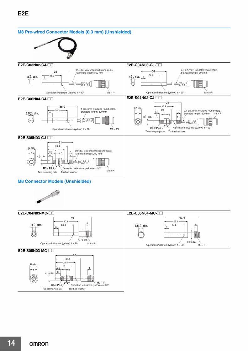
M8 Pre-wired Connector Models (0.3 m) (Shielded)
(Unit: mm)Tolerance class IT16 applies to dimensions in this data sheet unless otherwise specified.
Mounting Hole Dimensions
F
Pre-wired Models (Shielded)
Dimension 3 dia. 4 dia. 5.4 dia. 6.5 dia. M4 M5
F (mm) 3.3 4.2 5.7 7 4.5 5.5+0.50
+0.50
+0.50
+0.50
+0.50
+0.50
2.4-dia. vinyl-insulated round cable with 3 conductors (Conductor cross section: 0.09 mm2, Insulator diameter: 0.7 mm), Standard length: 2 m18
27.1
Operation indicators (yellow) 4 × 90°
3 0-0.1 dia.
E2E-C03SR8-WC-@@
18.5
25.14 0-0.1 dia.
Operation indicators (yellow) 4 × 90°* 2.9-dia. vinyl-insulated round cable with 3 conductors (Conductor cross section:
0.14 mm2, Insulator diameter: 0.8 mm), Standard length: 2 m Model with robot (bending-resistant) cable: 2.9-dia. vinyl-insulated round cable
with 3 conductors (Conductor cross section: 0.15 mm2, Insulator diameter: 1.05 mm), Standard length: 2 m
*
E2E-C04S12-WC-@@
18.5
25.15.4 0-0.1 dia.
Operation indicators (yellow) 4 × 90°*
* 2.9-dia. vinyl-insulated round cable with 3 conductors (Conductor cross section: 0.14 mm2, Insulator diameter: 0.8 mm), Standard length: 2 m
Model with robot (bending-resistant) cable: 2.9-dia. vinyl-insulated round cable with 3 conductors (Conductor cross section: 0.15 mm2,
Insulator diameter: 1.05 mm), Standard length: 2 m
E2E-C05S01-WC-@@36
24.16.5 0
-0.1 dia.
Operation indicators (yellow) 4 × 90°
* 4-dia. vinyl-insulated round cable with 3 conductors (Conductor cross section: 0.14 mm2, Insulator diameter: 0.85 mm), Standard length: 2 m
Model with robot (bending-resistant) cable: 4-dia. vinyl-insulated round cable with 3 conductors (Conductor cross section: 0.3 mm2,
Insulator diameter: 1.2 mm), Standard length: 2 m
*
E2E-C06S02-WC-@@
M4 × P0.5
5
1
27.1
15.1
73
8.5 dia.
0.6
18
Two clamping nuts Toothed washer
2.4-dia. vinyl-insulated round cable with 3 conductors (Conductor cross section: 0.09 mm2, Insulator diameter: 0.7 mm), Standard length: 2 m
Operation indicators (yellow) 4 × 90°
E2E-S04SR8-WC-@@
0.6
18.5
4
1
25.1
15.1
Operation indicators (yellow) 4 × 90°
8
10 dia.
Two clamping nuts Toothed washer
3
M5 × P0.5
* 2.9-dia. vinyl-insulated round cable with 3 conductors (Conductor cross section: 0.09 mm2, Insulator diameter: 0.7 mm), Standard length: 2 m
Model with robot (bending-resistant) cable: 2.9-dia. vinyl-insulated round cable with 3 conductors (Conductor cross section: 0.15 mm2,
Insulator diameter: 1.0 mm), Standard length: 2 m*
E2E-S05S12-WC-@@
M8 × P1
18
27.13 0-0.1 dia.
Operation indicators (yellow) 4 × 90°
2.4-dia. vinyl-insulated round cable, Standard length: 300 mm
E2E-C03SR8-CJ-@@
M8 × P1
18.5
25.14 0
-0.1 dia.2.9-dia. vinyl-insulated round cable, Standard length: 300 mm
Operation indicators (yellow) 4 × 90°
E2E-C04S12-CJ-@@
M8 × P1
24.1
366.5 0
-0.1 dia.
Operation indicators (yellow) 4 × 90°
4-dia. vinyl-insulated round cable, Standard length: 300 mm
E2E-C06S02-CJ-@@
0.6
M8 × P1
18
27.1
15.15
17
8.5 dia.
3
2.4-dia. vinyl-insulated round cable, Standard length: 300 mm
Two clamping nuts Toothed washerOperation indicators (yellow) 4 × 90°M4 × P0.5
E2E-S04SR8-CJ-@@
0.6
1
18.5
25.1
15.14
M8 × P18
10 dia.
32.9-dia. vinyl-insulated round cable, Standard length: 300 mm
Two clamping nuts Toothed washer
Operation indicators (yellow) 4 × 90°M5 × P0.5
E2E-S05S12-CJ-@@

E2E
13
M8 Connector Models (Shielded)
Pre-wired Models (Unshielded)
M8 × P1
6.75 dia.
Operation indicators (yellow) 4 × 90°
24.24
40.1
18.5
4 0-0.1 dia.
E2E-C04S12-MC-@@43.5
28.5
24.1
6.75 dia.M8 × P1
4
Operation indicators (yellow) 4 × 90°
6.5 0-0.1 dia.
E2E-C06S02-MC-@@
6.75 dia.
0.6
24.2
40.1
18.5
M8 × P1
4
15.1
8
10 dia.
Two clamping nutsToothed washer
3
Operation indicators (yellow) 4 × 90°M5 × P0.5
E2E-S05S12-MC-@@
Mounting Hole Dimensions
Dimension 3 dia. 4 dia. 6.5 dia. M4 M5
F (mm) 3.3 4.2 7 4.5 5.5+0.50
+0.50
+0.50
+0.50
+0.50
F
23.96
333 0
-0.1 dia.
Operation indicators (yellow) 4 × 90°
2.4-dia. vinyl-insulated round cable with 3 conductors (Conductor cross section: 0.09 mm2, Insulator diameter: 0.7 mm), Standard length: 2 m
E2E-C03N02-WC-@@
624.4
31
4 0-0.1 dia.
Operation indicators (yellow) 4 × 90°
* 2.9-dia. vinyl-insulated round cable with 3 conductors (Conductor cross section: 0.14 mm2, Insulator diameter: 0.8 mm), Standard length: 2 m
Model with robot (bending-resistant) cable: 2.9-dia. vinyl-insulated round cable with 3 conductors (Conductor cross section: 0.15 mm2,
Insulator diameter: 1.05 mm), Standard length: 2 m
*
E2E-C04N03-WC-@@
6
35.924.26.5 0
-0.1 dia.
Operation indicators (yellow) 4 × 90°
* 4-dia. vinyl-insulated round cable with 3 conductors (Conductor cross section: 0.14 mm2, Insulator diameter: 0.85 mm), Standard length: 2 m
Model with robot (bending-resistant) cable: 4-dia. vinyl-insulated round cable with 3 conductors (Conductor cross section: 0.3 mm2,
Insulator diameter: 1.2 mm), Standard length: 2 m
*
E2E-C06N04-WC-@@
6
6.5 5
1
23.9
33
21
7
8.5 dia.
3 dia.0-0.1
3
2.4-dia. vinyl-insulated round cable with 3 conductors (Conductor cross section: 0.09 mm2, Insulator diameter: 0.7 mm), Standard length: 2 m
Operation indicators (yellow) 4 × 90°Two clamping nuts Toothed washer
M4 × P0.5
E2E-S04N02-WC-@@
6.5
6
24.4
4
1
31
21
8
10 dia.
3
Operation indicators (yellow) 4 × 90°
Two clamping nuts Toothed washer
4 dia.0-0.1
M5 × P0.5
* 2.9-dia. vinyl-insulated round cable with 3 conductors (Conductor cross section: 0.14 mm2, Insulator diameter: 0.8 mm), Standard length: 2 m
Model with robot (bending-resistant) cable: 2.9-dia. vinyl-insulated round cable with 3 conductors (Conductor cross section: 0.15 mm2,
Insulator diameter: 1.05 mm), Standard length: 2 m
*
E2E-S05N03-WC-@@
E2E
14
M8 Pre-wired Connector Models (0.3 mm) (Unshielded)
M8 Connector Models (Unshielded)
6
M8 × P1
23.9
33
3 0-0.1 dia.
Operation indicators (yellow) 4 × 90°
2.4-dia. vinyl-insulated round cable, Standard length: 300 mm
E2E-C03N02-CJ-@@
6
M8 × P1
24.4
31
4 0-0.1 dia.
2.9-dia. vinyl-insulated round cable, Standard length: 300 mm
Operation indicators (yellow) 4 × 90°
E2E-C04N03-CJ-@@
6
M8 × P1
24.2
35.94-dia. vinyl-insulated round cable, Standard length: 300 mm
Operation indicators (yellow) 4 × 90°
6.5 0-0.1 dia.
E2E-C06N04-CJ-@@
6
6.5M8 × P1
21
23.9
33
5
1
7
8.5 dia.
3
2.4-dia. vinyl-insulated round cable, Standard length: 300 mm
3 dia.0-0.1
Two clamping nuts Toothed washer
Operation indicators (yellow) 4 × 90°M4 × P0.5
E2E-S04N02-CJ-@@
6.5
6
M8 × P1
24.4
31
214
18
10 dia.
32.9-dia. vinyl-insulated round cable, Standard length: 300 mm
Operation indicators (yellow) 4 × 90°
4 dia.0-0.1
Two clamping nuts Toothed washer
M5 × P0.5
E2E-S05N03-CJ-@@
6
M8 × P1
6.75 dia.
30.14
46
24.44 dia.
Operation indicators (yellow) 4 × 90°
0-0.1
E2E-C04N03-MC-@@
6
43.428.4
24.2
6.75 dia.M8 × P1
46.5 dia. 0
-0.1
Operation indicators (yellow) 4 × 90°
E2E-C06N04-MC-@@
6
6.5
24.4
30.1
46
21
M8 × P1
48
10 dia.
Operation indicators (yellow) 4 × 90°
Two clamping nuts Toothed washer
3
4 dia.0-0.1
M5 × P0.5
E2E-S05N03-MC-@@

E2E
15
Accessories (Sold Separately)Mounting Brackets
Material: Iron
9
2.4
23
1.5
125.5
Two hexagon nuts M3×P0.5
Two washers
Two hexagon socket head cap screws M3×20
0.5
14.5
25
3 dia.5.5 dia.
8 dia.
Y92E-SC03 (3-dia. block)
Material: Iron
9.5
2.4
23
1.5
125.5
0.5
14.5
25
4 dia. 5.5 dia.
Two hexagon nuts M3×P0.5
Two washers
Two hexagon socket head cap screws M3×20
8 dia.
Y92E-SC04 (4-dia. block)
Material: Iron
10.2
2.4
23
1.5
125.5
0.5
14.5
255.4 dia. 5.5 dia.
Two hexagon nuts M3×P0.5
Two washers
Two hexagon socket head cap screws M3×20
8 dia.
Y92E-SC05 (5.4-dia. block)
Material: Iron
10.8
2.4
23
1.5
125.5
0.5
14.5
25
6.5 dia.5.5 dia.
Two hexagon nuts M3×P0.5
Two washers
Two hexagon socket head cap screws M3×20
8 dia.
Y92E-SC06 (6.5-dia. block)
A
2.5 ± 0.05 dia.
Half punch
1
Cross sectional diagram A-A
2014±0.1
22
10 ± 0.1
8 ± 0.1
4 dia.
3.5 dia.
17
5
2A
(R2)
R 0.3 max.
Material: Iron
+0.10
Y92E-SS04 (for M4 screw)
A
2.5 ± 0.05 dia.
1
2014 ± 0.1
10 ± 0.1
8 ± 0.1
5.1 dia.
17
5
A
R2
R 0.3 max.
2-R1
2-R1
3.5dia.
22
2
Material: Iron
Half punch
Cross sectional diagram A-A
+0.10
Y92E-SS05 (for M5 screw)
E2E
16
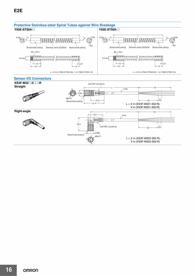
Protective Stainless-steel Spiral Tubes against Wire Breakage
Sensor I/O Connectors
Y92E-STS04-@
A A
M4 × P0.5
Brass/nickel platingBrass/nickel plating Stainless steel (SUS304)
L
12
16 12
2
L = 0.5 m (Y92E-STS04-05), 1 m (Y92E-STS04-10)
8 dia. 4 dia.
7 dia.
5.6 dia.
Y92E-STS05-@
A A
L
12
16 12
2
8 dia. 4 dia.
7 dia.
5.6 dia.
Brass/nickel platingBrass/nickel plating Stainless steel (SUS304)
M5 × P0.5
L = 0.5 m (Y92E-STS05-05), 1 m (Y92E-STS05-10)
XS3F-M32@-3@@-RStraight L
21.5
9 dia.
305
31.4
504
3 1
4 dia.
M8×P1
Soft PBT (UL94V-0)
Brass/nickel plating
L = 2 m (XS3F-M321-302-R),5 m (XS3F-M321-305-R)
9 dia.
L
4 dia.
305
20.5
23.1
50
M8×P14
3
1Brass/nickel plating
Soft PBT (UL94V-0)
Right-angle
L = 2 m (XS3F-M322-302-R),5 m (XS3F-M322-305-R)

Terms and Conditions of Sale1. Offer; Acceptance. These terms and conditions (these "Terms") are deemed
part of all quotes, agreements, purchase orders, acknowledgments, price lists,catalogs, manuals, brochures and other documents, whether electronic or inwriting, relating to the sale of products or services (collectively, the "Products")by Omron Electronics LLC and its subsidiary companies (“Omron”). Omronobjects to any terms or conditions proposed in Buyer’s purchase order or otherdocuments which are inconsistent with, or in addition to, these Terms.
2. Prices; Payment Terms. All prices stated are current, subject to change with-out notice by Omron. Omron reserves the right to increase or decrease priceson any unshipped portions of outstanding orders. Payments for Products aredue net 30 days unless otherwise stated in the invoice.
3. Discounts. Cash discounts, if any, will apply only on the net amount of invoicessent to Buyer after deducting transportation charges, taxes and duties, and willbe allowed only if (i) the invoice is paid according to Omron’s payment termsand (ii) Buyer has no past due amounts.
4. Interest. Omron, at its option, may charge Buyer 1-1/2% interest per month orthe maximum legal rate, whichever is less, on any balance not paid within thestated terms.
5. Orders. Omron will accept no order less than $200 net billing.6. Governmental Approvals. Buyer shall be responsible for, and shall bear all
costs involved in, obtaining any government approvals required for the impor-tation or sale of the Products.
7. Taxes. All taxes, duties and other governmental charges (other than generalreal property and income taxes), including any interest or penalties thereon,imposed directly or indirectly on Omron or required to be collected directly orindirectly by Omron for the manufacture, production, sale, delivery, importa-tion, consumption or use of the Products sold hereunder (including customsduties and sales, excise, use, turnover and license taxes) shall be charged toand remitted by Buyer to Omron.
8. Financial. If the financial position of Buyer at any time becomes unsatisfactoryto Omron, Omron reserves the right to stop shipments or require satisfactorysecurity or payment in advance. If Buyer fails to make payment or otherwisecomply with these Terms or any related agreement, Omron may (without liabil-ity and in addition to other remedies) cancel any unshipped portion of Prod-ucts sold hereunder and stop any Products in transit until Buyer pays allamounts, including amounts payable hereunder, whether or not then due,which are owing to it by Buyer. Buyer shall in any event remain liable for allunpaid accounts.
9. Cancellation; Etc. Orders are not subject to rescheduling or cancellationunless Buyer indemnifies Omron against all related costs or expenses.
10. Force Majeure. Omron shall not be liable for any delay or failure in deliveryresulting from causes beyond its control, including earthquakes, fires, floods,strikes or other labor disputes, shortage of labor or materials, accidents tomachinery, acts of sabotage, riots, delay in or lack of transportation or therequirements of any government authority.
11. Shipping; Delivery. Unless otherwise expressly agreed in writing by Omron:a. Shipments shall be by a carrier selected by Omron; Omron will not drop ship
except in “break down” situations.b. Such carrier shall act as the agent of Buyer and delivery to such carrier shall
constitute delivery to Buyer;c. All sales and shipments of Products shall be FOB shipping point (unless oth-
erwise stated in writing by Omron), at which point title and risk of loss shallpass from Omron to Buyer; provided that Omron shall retain a security inter-est in the Products until the full purchase price is paid;
d. Delivery and shipping dates are estimates only; ande. Omron will package Products as it deems proper for protection against nor-
mal handling and extra charges apply to special conditions.12. Claims. Any claim by Buyer against Omron for shortage or damage to the
Products occurring before delivery to the carrier must be presented in writingto Omron within 30 days of receipt of shipment and include the original trans-portation bill signed by the carrier noting that the carrier received the Productsfrom Omron in the condition claimed.
13. Warranties. (a) Exclusive Warranty. Omron’s exclusive warranty is that theProducts will be free from defects in materials and workmanship for a period oftwelve months from the date of sale by Omron (or such other period expressedin writing by Omron). Omron disclaims all other warranties, express or implied.(b) Limitations. OMRON MAKES NO WARRANTY OR REPRESENTATION,EXPRESS OR IMPLIED, ABOUT NON-INFRINGEMENT, MERCHANTABIL-
ITY OR FITNESS FOR A PARTICULAR PURPOSE OF THE PRODUCTS.BUYER ACKNOWLEDGES THAT IT ALONE HAS DETERMINED THAT THEPRODUCTS WILL SUITABLY MEET THE REQUIREMENTS OF THEIRINTENDED USE. Omron further disclaims all warranties and responsibility ofany type for claims or expenses based on infringement by the Products or oth-erwise of any intellectual property right. (c) Buyer Remedy. Omron’s sole obli-gation hereunder shall be, at Omron’s election, to (i) replace (in the formoriginally shipped with Buyer responsible for labor charges for removal orreplacement thereof) the non-complying Product, (ii) repair the non-complyingProduct, or (iii) repay or credit Buyer an amount equal to the purchase price ofthe non-complying Product; provided that in no event shall Omron be responsi-ble for warranty, repair, indemnity or any other claims or expenses regardingthe Products unless Omron’s analysis confirms that the Products were prop-erly handled, stored, installed and maintained and not subject to contamina-tion, abuse, misuse or inappropriate modification. Return of any Products byBuyer must be approved in writing by Omron before shipment. Omron Compa-nies shall not be liable for the suitability or unsuitability or the results from theuse of Products in combination with any electrical or electronic components,circuits, system assemblies or any other materials or substances or environ-ments. Any advice, recommendations or information given orally or in writing,are not to be construed as an amendment or addition to the above warranty.See http://www.omron247.com or contact your Omron representative for pub-lished information.
14. Limitation on Liability; Etc. OMRON COMPANIES SHALL NOT BE LIABLEFOR SPECIAL, INDIRECT, INCIDENTAL, OR CONSEQUENTIAL DAMAGES,LOSS OF PROFITS OR PRODUCTION OR COMMERCIAL LOSS IN ANYWAY CONNECTED WITH THE PRODUCTS, WHETHER SUCH CLAIM ISBASED IN CONTRACT, WARRANTY, NEGLIGENCE OR STRICT LIABILITY.Further, in no event shall liability of Omron Companies exceed the individualprice of the Product on which liability is asserted.
15. Indemnities. Buyer shall indemnify and hold harmless Omron Companies andtheir employees from and against all liabilities, losses, claims, costs andexpenses (including attorney's fees and expenses) related to any claim, inves-tigation, litigation or proceeding (whether or not Omron is a party) which arisesor is alleged to arise from Buyer's acts or omissions under these Terms or inany way with respect to the Products. Without limiting the foregoing, Buyer (atits own expense) shall indemnify and hold harmless Omron and defend or set-tle any action brought against such Companies to the extent based on a claimthat any Product made to Buyer specifications infringed intellectual propertyrights of another party.
16. Property; Confidentiality. Any intellectual property in the Products is the exclu-sive property of Omron Companies and Buyer shall not attempt to duplicate itin any way without the written permission of Omron. Notwithstanding anycharges to Buyer for engineering or tooling, all engineering and tooling shallremain the exclusive property of Omron. All information and materials suppliedby Omron to Buyer relating to the Products are confidential and proprietary,and Buyer shall limit distribution thereof to its trusted employees and strictlyprevent disclosure to any third party.
17. Export Controls. Buyer shall comply with all applicable laws, regulations andlicenses regarding (i) export of products or information; (iii) sale of products to“forbidden” or other proscribed persons; and (ii) disclosure to non-citizens ofregulated technology or information.
18. Miscellaneous. (a) Waiver. No failure or delay by Omron in exercising any rightand no course of dealing between Buyer and Omron shall operate as a waiverof rights by Omron. (b) Assignment. Buyer may not assign its rights hereunderwithout Omron's written consent. (c) Law. These Terms are governed by thelaw of the jurisdiction of the home office of the Omron company from whichBuyer is purchasing the Products (without regard to conflict of law princi-ples). (d) Amendment. These Terms constitute the entire agreement betweenBuyer and Omron relating to the Products, and no provision may be changedor waived unless in writing signed by the parties. (e) Severability. If any provi-sion hereof is rendered ineffective or invalid, such provision shall not invalidateany other provision. (f) Setoff. Buyer shall have no right to set off any amountsagainst the amount owing in respect of this invoice. (g) Definitions. As usedherein, “including” means “including without limitation”; and “Omron Compa-nies” (or similar words) mean Omron Corporation and any direct or indirectsubsidiary or affiliate thereof.
Certain Precautions on Specifications and Use1. Suitability of Use. Omron Companies shall not be responsible for conformity
with any standards, codes or regulations which apply to the combination of theProduct in the Buyer’s application or use of the Product. At Buyer’s request,Omron will provide applicable third party certification documents identifyingratings and limitations of use which apply to the Product. This information byitself is not sufficient for a complete determination of the suitability of the Prod-uct in combination with the end product, machine, system, or other applicationor use. Buyer shall be solely responsible for determining appropriateness ofthe particular Product with respect to Buyer’s application, product or system.Buyer shall take application responsibility in all cases but the following is anon-exhaustive list of applications for which particular attention must be given:(i) Outdoor use, uses involving potential chemical contamination or electricalinterference, or conditions or uses not described in this document.(ii) Use in consumer products or any use in significant quantities.(iii) Energy control systems, combustion systems, railroad systems, aviationsystems, medical equipment, amusement machines, vehicles, safety equip-ment, and installations subject to separate industry or government regulations. (iv) Systems, machines and equipment that could present a risk to life or prop-erty. Please know and observe all prohibitions of use applicable to this Prod-uct. NEVER USE THE PRODUCT FOR AN APPLICATION INVOLVING SERIOUSRISK TO LIFE OR PROPERTY OR IN LARGE QUANTITIES WITHOUTENSURING THAT THE SYSTEM AS A WHOLE HAS BEEN DESIGNED TO
ADDRESS THE RISKS, AND THAT THE OMRON’S PRODUCT IS PROP-ERLY RATED AND INSTALLED FOR THE INTENDED USE WITHIN THEOVERALL EQUIPMENT OR SYSTEM.
2. Programmable Products. Omron Companies shall not be responsible for theuser’s programming of a programmable Product, or any consequence thereof.
3. Performance Data. Data presented in Omron Company websites, catalogsand other materials is provided as a guide for the user in determining suitabil-ity and does not constitute a warranty. It may represent the result of Omron’stest conditions, and the user must correlate it to actual application require-ments. Actual performance is subject to the Omron’s Warranty and Limitationsof Liability.
4. Change in Specifications. Product specifications and accessories may bechanged at any time based on improvements and other reasons. It is our prac-tice to change part numbers when published ratings or features are changed,or when significant construction changes are made. However, some specifica-tions of the Product may be changed without any notice. When in doubt, spe-cial part numbers may be assigned to fix or establish key specifications foryour application. Please consult with your Omron’s representative at any timeto confirm actual specifications of purchased Product.
5. Errors and Omissions. Information presented by Omron Companies has beenchecked and is believed to be accurate; however, no responsibility is assumedfor clerical, typographical or proofreading errors or omissions.

OMRON CANADA, INC. • HEAD OFFICEToronto, ON, Canada • 416.286.6465 • 866.986.6766 • www.omron247.com
OMRON ELECTRONICS DE MEXICO • HEAD OFFICEMéxico DF • 52.55.59.01.43.00 • 01-800-226-6766 • [email protected]
OMRON ELECTRONICS DE MEXICO • SALES OFFICEApodaca, N.L. • 52.81.11.56.99.20 • 01-800-226-6766 • [email protected]
OMRON ELETRÔNICA DO BRASIL LTDA • HEAD OFFICESão Paulo, SP, Brasil • 55.11.2101.6300 • www.omron.com.br
OMRON ARGENTINA • SALES OFFICECono Sur • 54.11.4783.5300
OMRON CHILE • SALES OFFICESantiago • 56.9.9917.3920
OTHER OMRON LATIN AMERICA SALES54.11.4783.5300
Authorized Distributor:
E55I-E-03 12/14 Note: Specifications are subject to change. © 2014 Omron Electronics LLC Printed in U.S.A.
Printed on recycled paper.
Automation Control Systems• Machine Automation Controllers (MAC) • Programmable Controllers (PLC) • Operator interfaces (HMI) • Distributed I/O • Software
Drives & Motion Controls • Servo & AC Drives • Motion Controllers & Encoders
Temperature & Process Controllers • Single and Multi-loop Controllers
Sensors & Vision• Proximity Sensors • Photoelectric Sensors • Fiber-Optic Sensors• Amplified Photomicrosensors • Measurement Sensors• Ultrasonic Sensors • Vision Sensors
Industrial Components • RFID/Code Readers • Relays • Pushbuttons & Indicators• Limit and Basic Switches • Timers • Counters • Metering Devices • Power Supplies
Safety • Laser Scanners • Safety Mats • Edges and Bumpers • Programmable Safety Controllers • Light Curtains • Safety Relays • Safety Interlock Switches
OMRON AUTOMATION AND SAFETY • THE AMERICAS HEADQUARTERS • Chicago, IL USA • 847.843.7900 • 800.556.6766 • www.omron247.com
OMRON EUROPE B.V. • Wegalaan 67-69, NL-2132 JD, Hoofddorp, The Netherlands. • +31 (0) 23 568 13 00 • www.industrial.omron.eu