SMACNA Symbols for Ducting
149
SMACNA CAD STANDARD SHEET METAL AND AIR CONDITIONING CONTRACTORS’ NATIONAL ASSOCIATION, INC.
-
Upload
thiru-kumar -
Category
Documents
-
view
206 -
download
17
description
SMCANA
Transcript of SMACNA Symbols for Ducting

SMACNA CADSTANDARD
SHEET METAL AND AIR CONDITIONING CONTRACTORS’NATIONAL ASSOCIATION, INC.


SMACNA CADSTANDARD
SECOND EDITION – JULY 2001
SHEET METAL AND AIR CONDITIONING CONTRACTORS’NATIONAL ASSOCIATION, INC.
4201 Lafayette Center DriveChantilly, VA 20151--1209

SMACNA CAD STANDARDCOPYRIGHTE2001All Rights Reserved
by
SHEET METAL AND AIR CONDITIONING CONTRACTORS’NATIONAL ASSOCIATION, INC.
4201 Lafayette Center DriveChantilly, VA 20151--1209
Printed in the U.S.A.
FIRST EDITION -- 1996SECOND EDITION – JULY 2001
Except as allowed in the Notice to Users and in certain licensing contracts, no part of this book may bereproduced, stored in a retrievable system, or transmitted, in any form or by any means, electronic,
mechanical, photocopying, recording, or otherwise, without the prior written permission of the publisher.

iiiSMACNA CAD Standard Second Edition
FOREWORD
The SMACNACADSTANDARD (SCS), formerly calledCADD Symbols and LayeringGuidelines in its first edition,embraces the idea that computer-aided design (CAD) has become indispensable to the architecture/ engineering/construction (AEC) industry. Not only has CAD software improved drafting efficiency and the overall productivityof the construction professional, but now building owners are realizing the potential of automated controls and elec-tronic record keeping and are requesting data in electronic format from construction professionals.
Now that they have learned to communicate with the computer, many designers and builders are using computers toimprove communications with each other. In order to share electronic information efficiently, it’s essential that allparties speak the same language. For members of the endorsing organizations, it’s important that the mechanical,plumbing, and fire protection information be labeled and located consistently in CAD files so that it is easily foundand manipulated. For building owners and design professionals, it’s important that such data be consistently storedwithin their ownCADfiles in accordwith amutually agreed protocol or standard. To ensure consistency it is importantto organize data into predefined “layers”, to apply identical graphic symbols to components, and to use consistent ter-minology and abbreviations.
SCS is designed to encourage consistency by building upon the second edition of the National CAD Standard (NCS)published by the National Institute of Building Sciences in 2001. NCS incorporates the efforts of the American Insti-tute of Architects (AIA) and its CAD Layer Guidelines as well as the Construction Specifications Institute (CSI) andits Uniform Drawing System. As an organization with contributing members on the NCS Committee, SMACNA iscommitted to improving electronic communication between members of the AEC community and the overall qualityof their work.
In this current edition of SCS, SMACNA has extended NCS by drawing upon the considerable experience of its ownCADD Task Force. SCS articulates the CAD standards that will enable SMACNAmembers and the rest of the AECcommunity to apply CAD effectively to mechanical, fire protection, and plumbing design and construction.
This document is available in electronic format by accessing http://www.smacna.org on the Internet.
SHEET METAL AND AIR CONDITIONING CONTRACTORS’NATIONAL ASSOCIATION, INC.

iv SMACNA CAD Standard Second Edition
CADD TASK FORCERichard E. Brown, ChairmanRabe Environmental Systems, Inc.Erie, Pennsylvania
Robert Buckley, Jr.Anderson, Rowe & Buckley, Inc.San Francisco, California
Ken CastroTRI-C Sheet Metal, Inc.Cleveland, Ohio
Roy JensenMechOne, Inc.Colorado Springs, Colorado
Gary L. Joaquin, Technical WriterJLG & AssociatesAnnandale, Virginia
G. A. Navas, Staff LiaisonSMACNA, Inc.Chantilly, Virginia
FORMER COMMITTEE MEMBERSAND OTHER CONTRIBUTORS
The following individuals and organizations participated in the development of the CADD Symbols and LayeringGuidelines, 1st edition.
SMACNA COMPUTER COMMITTEEGary C. Carvetta, ChairmanTriangle Mechanical, Inc.
Phillip GillespieBrad Snodgrass, Inc.
Mark Allan SiebertProduction Services, Inc.
Mark WatsonClimate Engineers, Inc.
OTHER CONTRIBUTORSCentral Indiana Chapter CAD Users GroupIndianapolis, Indiana
Phillip E. Gillespie, ChairmanBrad Snodgrass, Inc.
Gary BaldwinApex Ventilating Company, Inc.
Curtis BondBrad Snodgrass, Inc.
Robert L GoshertSimon Property Group, Inc.
Michael JohnsonBrad Snodgrass, Inc.
Phil KrischBrad Snodgrass, Inc.
Darryl A. McClellandMcClelland Consulting
Rick McKeeBrad Snodgrass, Inc.
Robert OvertonIndiana Government Center—Public Works Division
Bill ParadiseApex Ventilating Company, Inc.
Greg StephensMusset Nicholas and Associates, Inc.
Loyd VandagriffBrad Snodgrass, Inc.—Ford Motor Co.
Michael L. WentworthBSA Design

SMACNA CAD Standard Second Edition v
NOTICE TO USERSOF THIS PUBLICATION
1. DISCLAIMER OF WARRANTIES
a) The Sheet Metal and Air Conditioning Contractor’s National Association (“SMACNA”) provides its product for informationalpurposes.
b) The product contains “Data” which is believed by SMACNA to be accurate and correct but the data, including all information,ideas and expressions therein, is provided strictly “AS IS”, with all faults. SMACNA makes no warranty either express or impliedregarding the Data and SMACNA EXPRESSLY DISCLAIMS ANY IMPLIED WARRANTIES OF MERCHANTABILITY ORFITNESS FOR PARTICULAR PURPOSE.
c) By using the data contained in the product user accepts the Data “AS IS” and assumes all risk of loss, harm or injury that may resultfrom its use. User acknowledges that the Data is complex, subject to faults and requires verification by competent professionals, andthat modification of parts of the Data by user may impact the results or other parts of the Data.
d) IN NO EVENT SHALL SMACNA BE LIABLE TO USER, OR ANY OTHER PERSON, FOR ANY INDIRECT, SPECIAL ORCONSEQUENTIAL DAMAGES ARISING, DIRECTLY OR INDIRECTLY, OUT OF OR RELATED TO USER’S USE OFSMACNA’S PRODUCT OR MODIFICATION OF DATA THEREIN. This limitation of liability applies even if SMACNA has beenadvised of the possibility of such damages. IN NO EVENT SHALL SMACNA’S LIABILITY EXCEED THE AMOUNT PAID BYUSER FOR ACCESS TO SMACNA’S PRODUCT OR $1,000.00, WHICHEVER IS GREATER, REGARDLESS OF LEGALTHEORY.
e) User by its use of SMACNA’s product acknowledges and accepts the foregoing limitation of liability and disclaimer of warrantyand agrees to indemnify and hold harmless SMACNA from and against all injuries, claims, loss or damage arising, directly or indi-rectly, out of user’s access to or use of SMACNA’s product or the Data contained therein.
2. ACCEPTANCE
This document or publication is prepared for voluntary acceptance and use within the limitations of application defined herein, andotherwise as those adopting it or applying it deem appropriate. It is not a safety standard. Its application for a specific project is contin-gent on a designer or other authority defining a specific use. SMACNA has no power or authority to police or enforce compliance withthe contents of this document or publication and it has no role in any representations by other parties that specific components are, infact, in compliance with it.
3. AMENDMENTS
The Association may, from time to time, issue formal interpretations or interim amendments, which can be of significance betweensuccessive editions.
4. PROPRIETARY PRODUCTS
SMACNA encourages technological development in the interest of improving the industry for thepublic benefit. SMACNA doesnot,however, endorse individual manufacturers or products.
5. FORMAL INTERPRETATION
a) A formal interpretation of the literal text herein or the intent of the technical committee or task force associated with the documentor publication is obtainable only on the basis of written petition, addressed to the Technical Resources Department and sent to theAssociation’s national office in Chantilly, Virginia. In the event that the petitioner has a substantive disagreement with the interpreta-tion, an appeal may be filed with the Technical Resources Committee, which has technical oversight responsibility. The request mustpertain to a specifically identified portion of the document that does not involve published text which provides the requested informa-tion. In considering such requests, the Association will not review or judge products or components as being in compliance with thedocument or publication. Oral and written interpretations otherwise obtained from anyone affiliated with the Association are unoffi-cial. This procedure does not prevent any committee or task force chairman, member of the committee or task force, or staff liaisonfrom expressing an opinion on a provision within the document, provided that such person clearly states that the opinion is personaland does not represent an official act of the Association in any way, and it should not be relied on as such. The Board of Directors ofSMACNA shall have final authority for interpretation of this standard with such rules or procedures as they may adopt for processingsame.
b) SMACNA disclaims any liability for any personal injury, property damage, or other damage of any nature whatsoever, whetherspecial, indirect, consequential or compensatory, direct or indirectly resulting from the publication, use of, or reliance upon this docu-ment. SMACNA makes no guaranty or warranty as to the accuracy or completeness of any information published herein.
6. APPLICATION
a) Any standards contained in this publication were developed using reliable engineering principles and research plus consultationwith, and information obtained from, manufacturers, users, testing laboratories, and others having specialized experience. They are

vi SMACNA CAD Standard Second Edition
subject to revision as further experience and investigation may show is necessary or desirable. Construction and products which com-ply with these Standards will not necessarily be acceptable if, when examined and tested, they are found to have other features whichimpair the result contemplated by these requirements. The Sheet Metal and Air Conditioning Contractors’ National Association andother contributors assume no responsibility and accept no liability for the application of the principles or techniques contained in thispublication. Authorities considering adoption of any standards contained herein should review all federal, state, local, and contractregulations applicable to specific installations.
b) In issuing and making this document available, SMACNA is not undertaking to render professional or other services for or onbehalf of any person or entity. SMACNA is not undertaking to perform any duty owed to any person or entity to someone else. Anyperson or organization using this document should rely on his, her or its own judgement or, as appropriate, seek the advice of a compe-tent professional in determining the exercise of reasonable care in any given circumstance.
7. REPRINT PERMISSION
Non--exclusive, royalty--free permission is granted to government and private sector specifying authorities to reproduce only anyconstruction details found herein in their specifications and contract drawings prepared for receipt of bids on new construction andrenovation work within the United States and its territories, provided that the material copied is unaltered in substance and that thereproducer assumes all liability for the specific application, including errors in reproduction.
8. THE SMACNA LOGO
The SMACNA logo is registered as a membership identification mark. The Association prescribes acceptable use of the logo andexpressly forbids the use of it to represent anything other than possession of membership. Possession of membership and use of thelogo in no way constitutes or reflects SMACNA approval of any product, method, or component. Furthermore, compliance of anysuch item with standards published or recognized by SMACNA is not indicated by presence of the logo.

TABLE OF CONTENTS


TABLE OF CONTENTS
viiSMACNA CAD Standard Second Edition
FOREWORD iii. . . . . . . . . . . . . . . . . . . . . . . . . . . . . . . . . . . . . . . . . . . . . . . . . . . . . . . . . . . . . . . . . . . . . . . . . . . .
TASK FORCE iv. . . . . . . . . . . . . . . . . . . . . . . . . . . . . . . . . . . . . . . . . . . . . . . . . . . . . . . . . . . . . . . . . . . . . . . . . . . .
NOTICE TO USERS OF THIS PUBLICATION v. . . . . . . . . . . . . . . . . . . . . . . . . . . . . . . . . . . . . . . . . . . . . . . . .
TABLE OF CONTENTS vii. . . . . . . . . . . . . . . . . . . . . . . . . . . . . . . . . . . . . . . . . . . . . . . . . . . . . . . . . . . . . . . . . . . .
CHAPTER 1 INTRODUCTION 1.1. . . . . . . . . . . . . . . . . . . . . . . . . . . . . . . . . . . . . . . . . . . . . . . . . . . . . . . . . . .
1.1 HOW TO USE THIS PUBLICATION 1.1. . . . . . . . . . . . . . . . . . . . . . . . . . . . . . . . . . . . . . . . . . .1.2 READER FEEDBACK 1.1. . . . . . . . . . . . . . . . . . . . . . . . . . . . . . . . . . . . . . . . . . . . . . . . . . . . . . .
CHAPTER 2 LAYER STANDARDS 2.1. . . . . . . . . . . . . . . . . . . . . . . . . . . . . . . . . . . . . . . . . . . . . . . . . . . . . . .
2.1 WHAT ARE CAD LAYERS? 2.1. . . . . . . . . . . . . . . . . . . . . . . . . . . . . . . . . . . . . . . . . . . . . . . . . .2.2 WHY ARE CAD LAYERS IMPORTANT? 2.1. . . . . . . . . . . . . . . . . . . . . . . . . . . . . . . . . . . . . . .2.3 A SIMPLER SMACNA CAD LAYER GUIDELINE 2.1. . . . . . . . . . . . . . . . . . . . . . . . . . . . . . . .2.4 BACKGROUND OF THE SMACNA CAD STANDARD 2.1. . . . . . . . . . . . . . . . . . . . . . . . . . .2.5 LAYER STRUCTURE 2.2. . . . . . . . . . . . . . . . . . . . . . . . . . . . . . . . . . . . . . . . . . . . . . . . . . . . . . .2.6 GUIDELINES FOR LAYER USE 2.3. . . . . . . . . . . . . . . . . . . . . . . . . . . . . . . . . . . . . . . . . . . . . .2.7 MECHANICAL LAYERS 2.4. . . . . . . . . . . . . . . . . . . . . . . . . . . . . . . . . . . . . . . . . . . . . . . . . . . . .2.8 PLUMBING LAYERS 2.7. . . . . . . . . . . . . . . . . . . . . . . . . . . . . . . . . . . . . . . . . . . . . . . . . . . . . . . .2.9 FIRE PROTECTION LAYERS 2.7. . . . . . . . . . . . . . . . . . . . . . . . . . . . . . . . . . . . . . . . . . . . . . . .2.10 DRAWING VIEW LAYER LIST 2.8. . . . . . . . . . . . . . . . . . . . . . . . . . . . . . . . . . . . . . . . . . . . . . . .2.11 THREE DIMENSIONAL DRAWINGS 2.8. . . . . . . . . . . . . . . . . . . . . . . . . . . . . . . . . . . . . . . . . .2.12 ANNOTATION LAYERS 2.9. . . . . . . . . . . . . . . . . . . . . . . . . . . . . . . . . . . . . . . . . . . . . . . . . . . . . .2.13 SAMPLE DRAWING ORGANIZATION 2.10. . . . . . . . . . . . . . . . . . . . . . . . . . . . . . . . . . . . . . .2.14 ANNOTATION LAYERS AND INTERNATIONAL STANDARDS 2.11. . . . . . . . . . . . . . . . . . .
CHAPTER 3 ABBREVIATIONS 3.1. . . . . . . . . . . . . . . . . . . . . . . . . . . . . . . . . . . . . . . . . . . . . . . . . . . . . . . . . .
CHAPTER 4 DUCT SYMBOLS 4.1. . . . . . . . . . . . . . . . . . . . . . . . . . . . . . . . . . . . . . . . . . . . . . . . . . . . . . . . . . .
CHAPTER 5 EQUIPMENT SYMBOLS 5.1. . . . . . . . . . . . . . . . . . . . . . . . . . . . . . . . . . . . . . . . . . . . . . . . . . . .
CHAPTER 6 CENTRIFUGAL FAN SYMBOLS 6.1. . . . . . . . . . . . . . . . . . . . . . . . . . . . . . . . . . . . . . . . . . . . .
CHAPTER 7 PIPING SYMBOLS 7.1. . . . . . . . . . . . . . . . . . . . . . . . . . . . . . . . . . . . . . . . . . . . . . . . . . . . . . . . .
CHAPTER 8 ENVIRONMENTAL CONTROL SYMBOLS 8.1. . . . . . . . . . . . . . . . . . . . . . . . . . . . . . . . . . . .
CHAPTER 9 FIRE PROTECTION SYMBOLS 9.1. . . . . . . . . . . . . . . . . . . . . . . . . . . . . . . . . . . . . . . . . . . . .
APPENDIX A CAD PROJECT PROTOCOL A.1. . . . . . . . . . . . . . . . . . . . . . . . . . . . . . . . . . . . . . . . . . . . . . . .
APPENDIX B CAD PROJECT SPECIFICATION -- CHECK LIST B.1. . . . . . . . . . . . . . . . . . . . . . . . . . . . .
APPENDIX C THE CAD PROJECT -- CHECK LIST C.1. . . . . . . . . . . . . . . . . . . . . . . . . . . . . . . . . . . . . . . . .
APPENDIX D TRANSMITTAL LETTER D.1. . . . . . . . . . . . . . . . . . . . . . . . . . . . . . . . . . . . . . . . . . . . . . . . .


CHAPTER 1
INTRODUCTION

INTRODUCTIONCHAPTER 1
1.1SMACNA CAD Standard Second Edition
1.1 HOW TO USE THIS PUBLICATION
This publication is designed to be an easy to use quickreference guide. The information it contains is orga-nized and presented in three discrete categories: lay-ers, abbreviations, and symbols.
Chapter 2 describes standard layers based upon theNational CAD Standard (NCS) which include manynew additions introduced by members of SMACNA’sCADDTask Force who participated on the NCSCom-mittee. This flexible standard is well documented andprovides several concrete examples of efficient layeruse.
Chapter 3 provides a list of standard abbreviationswhich are a combination of the abbreviations found inSMACNA’s first edition of the CADD Symbols andLayering Guidelines and the standard abbreviationslisted in the Construction Specification Institute’sUniform Drawing System, part of NCS.
Chapters 4 though 9 list standard drafting symbols,grouped by construction component category. Thesesymbols come from a variety of sources and are now
assembled together into one comprehensive source tobe used by the mechanical trades. All of the symbolblocks in this publication may be downloaded fromhttp://www.smacna.org.
Experienced CAD users and novices alike can turn toAppendix A for a more complete overview of the re-quirements for implementing an office CADstandard.Useful checklists and a CADdocument submittal formare provided in the remaining appendices.
1.2 READER FEEDBACK
The layers, abbreviations, symbols, and protocols de-scribed in this book are part of an evolving standard.Users are encouraged to offer comments and sugges-tions after they have reviewed and used this materialin practice. Please send your feedback to:
SMACNAAttn: SMACNA CAD STANDARD
4201 Lafayette Center DriveChantilly, VA 20151-1209

1.2 SMACNA CAD Standard Second Edition
THIS PAGE INTENTIONALLY LEFT BLANK

CHAPTER 2
LAYERS


LAYERSCHAPTER 2
2.1SMACNA CAD Standard Second Edition
2.1 WHAT ARE CAD LAYERS?
One of the best ways to understand CAD layers is toimagine drafting manually on many stacked sheets orlayers of transparent acetate. Starting at the bottom ofthe pile is a layer of acetate on which only the buildingwalls are drawn. Following an office standard, thedraftermight place another acetate layer on top of that,and while seeing through to the wall layer, draw thedoor swings. Another layer might contain only the airconditioning equipment. When all the layers arestacked and aligned, a complete, if complex andcrowded, picture of the entire building is viewed. Se-lected layers can be removed and recombined to givean uncluttered view of items of particular interest. Forexample, an HVAC contractor might select only thesheets with the walls and the air conditioning equip-ment. A construction supervisor might want to ex-amine the piping and ductwork in isolation to ensurethat there are no interferences that will create costlyconflicts during construction.
CAD systems manipulate layers of information fasterthan any manual drafting process. Using CAD soft-ware, drafters can turn layers on and off, controllingwhich layers are displayed and edited at any giventime, for any given purpose. When properly used,CAD systems generate drawings that are simpler andeasier to read. For example, a complex job like a hospi-tal may have so muchmechanical work that to displayit all in one drawingwould be completely illegible.Al-though the drawing data may all reside in a single filefor computer storage efficiency, a crew installing ter-minal units doesn’t necessarily need to see all of theductwork and piping. They may only need a drawingon the job site that displays only the wall and terminalunit layers. CAD systems provide themeans to displayonly the most relevant information.
2.2 WHY ARE CAD LAYERSIMPORTANT?
Adhering to a consistent andmutuallywell understoodCAD layer standard gives professionals a commoncommunications vocabularywhich is vital today sinceso many construction drawings and so much data isshared electronically. Without a CAD layer standard,sharing drawings between twoCADsystems or simplytrying to read electronic drawingsprepared by another,even in one’s own office, can be difficult, time con-suming, or even impossible. Streamlining the flow ofdata through the use of a consistent layering standardmeans less duplication of effort in producing draw-
ings, more accurate bids, reduced construction timeand costs, and fewer construction errors in the field.
2.3 A SIMPLER SMACNA CAD LAYERGUIDELINE
The CADLayerGuidelines in this current edition havebeen revised and simplified substantially since theywere first released in SMACNA’s 1996 edition of theCADD Symbols and Layering Guidelines, and withgood reason. After careful examination, SMACNAdetermined that most of the layers variables definedfor material types, classification and gages, and spe-cial conditions identified in the first edition are moreappropriately stored in CAD drawing files as attributedata and do not necessarily require their own separatelayers.Using attribute data performsa similar functionfor character based data, that layers do for visual data.Layers enable CAD users to organize building infor-mation into visual reports where layers are selectivelyturned on and off to produce a drawing displaying spe-cific information. Attribute data enables characterbased data to be stored in a drawing, typically at theblock level as a property, where it can be selectivelyretrieved for the purpose of generating character basedreports summarizing important properties like projectcost or existing building conditions.
2.4 BACKGROUND OF THE SMACNACAD STANDARD
SMACNA’s first edition CAD Layer Guidelines de-fined layer names with a maximum length of eightcharacters to speeddata entry. CADsystems likeAuto-CADRweremore character based and, typically, CADusers typed in layer names, so the shorter the name thebetter. Today’s CAD systems support layer names upto 255 characters in lengthwithmuch greater flexibili-ty. This is the environment in which the latest versionof the National CAD Standard (NCS) layer guidelineswas developed by the American Institute of Archi-tects. This standard is a much more legible one usinga maximum of 18 characters. In an effort to complywith NCS and the larger AEC community SMACNAhas adopted the NCSstandard in principle and expand-ed upon it, providing standard layer names for a widerrange of mechanical, fire protection, and plumbingcomponents. Credit should be given to the UniversityofMinnesotawhoseDepartment of FacilitiesManage-ment made substantial contributions to SMACNA’seffort to refine its layer standard. Credit should also begiven to the Department of Defense’s Tri-ServicesCAD/GISCenter and the role that it has played in stan-dardizing the use of CAD layers.

2.2 SMACNA CAD Standard Second Edition
2.5 LAYER STRUCTURE
Recent CAD software releases have supported muchlonger layer names making it easier to recognize thecontents of a layer from its name alone. While CADsoftware can support layer names of up to 255 charac-ters, the ultimate limitation is the human interface;CADusers can only comprehend andmanipulate layernames that are of a practical length. So rather than usethe maximum number of characters in a layer name,SMACNA has adopted the NCS standard for its brev-ity, clarity, and consistency. SMACNA’s layer namingstandard uses a minimum of 6 characters up to a maxi-mum of 18 characters. Hyphens are inserted at precisepositions to separate layer names into logical and easi-ly readable components as follows:
Discipline
Major Group
Minor Group
Minor Group ModifierStatus
M NHVAC SDFF XXXX
where each field is defined as follows:
Discipline is a mandatory one-character field describ-ing the discipline underwhich a layer’s content is cate-gorized. SMACNA recommends three disciplines, Ffor Fire Protection, M for Mechanical, and P forPlumbing, resulting in standard layer names likeF-PROT, M-HVAC and P-STRM.
It is important to note explicitly that the purpose of thediscipline field is not to identify the author of a layer.Disciplines frequently do work traditionally per-formed by other disciplines, especially on smaller pro-jects. Using the discipline field to denote layer author-ship would introduce inconsistency into layer names,not only across industries, but even with small offices,thus this interpretation is not supported by the SMAC-NA standard.
SMACNA recognizes that NCS has expanded its owndiscipline field to include anoptional second characterwhere required. SMACNA supports the expansion ofthis field where it is used to further denote layer con-tent, not authorship.
Major Group is a mandatory four-character field de-scribing building systems. Generally,major groups areassociated with a specific discipline; however, it ispossible for the responsibility of a major group to beshared by two disciplines resulting in layer names like
M-HVAC and P-HVAC. Annotation, *-ANNO-*, isthe only major group that is not a building system. Itis described separately in section 2.12.
Minor Group is an optional four-character field usedto further differentiate major groups, e.g. the need toseparate supply and return ductwork results in the lay-er names M-HVAC-SDFF and M-HVAC-RDFF.While the majority of minor groups modify a specificmajor group, fourminor groupsmay be used tomodifyvirtually all of the major groups:
ELEV: denotes an elevation view,e.g. M-HVAC-ELEV
IDEN: denotes symbols or textthat need to remain oneven when text layers areturned off, e.g. M-HVAC-IDEN.
PATT: denotes hatch patterns,e.g. M-HVAC-PATT.
RDME: denotes read-me layer,text not to be plotted, e.g.M-HVAC-RDME
Minor Group Modifier is an optional four-characterfield used to further differentiate minor groups, e.g.M-HVAC-DOOR-IDEN denotes labels that identifymechanical access doors.
Status is an optional one character field describing theconstruction state of a layer’s contents:
N New Work
E Existing to Remain
D Existing to Demolish
F Future Work
T Temporary Work
M Items to Be Moved
R Relocated Items
X Not in Contract
1-9 Phase Numbers
A As Built
e.g. M-HVAC-RETN-D denotes a layer containingMechanical-Heating, Ventilation, and Air Condition-ing - Return Ducts - To Be Demolished.

2.3SMACNA CAD Standard Second Edition
2.6 GUIDELINES FOR LAYER USE
1. Use only the layers that your work requires.Develop a list of standard layers for yourpractice by selecting layers from the standardlists provided in these guidelines. If you donot find all of the layer names that you need,create your own newmajor groups alongwithnew minor group and minor group modifierfields. These guidelines are intended to beflexible and to provide a structure fromwhichto define new layers.
2. It is important that each layer name field haveexactly the same number of characters thatare specified in this standard, e.g. the majorgroup field must contain four and exactlyfour characters. Adhering to a consistent lay-er standard enables each character position ina layer name to retain the same meaning,making it easier to turn groups of layers onand off with layer name wild cards.
3. Don’t use more layer fields than your workrequires. The minimum layer name requiresonly themandatory fields, discipline andma-jor group. These are frequently sufficient todescribe the contents of a layer.
4. Layer fields are interchangeable and may becombined in an infinite number of ways aslong as they describe a system that actuallyexists, e.g. P-CHIM-FLDR denoting floordrains installed in a chimney by a plumbingdiscipline is not a physically meaningful lay-er name.
5. To be in compliance with these layer guide-lines, do not rename layers that are alreadydefined, e.g. M-HVAC-EQPM is in com-pliance while M-HVAC-EQPT is not.
6. To ensure consistent layer use in your prac-tice, create drawing template files containingstandard layers for each type of drawing thatyou produce. Use script files to add layers totemplate files. Creating new layers manuallycan be very error prone and should be avoi-ded. Develop scripts to create layers required
for amajor groupor a set ofmajor groups.De-velop versions of these script files, one fornew construction with its shorter layer listand another for renovation projects with thelonger layer list required to describeconstruction status, to name but a couple ofconditions. Use these scripts in combinationto produce template files for the simplest andthe most complex projects. Scripts may alsobe used to add new layers to active projectswhose scope has increased.
Note that the latest CAD software releasesnow include menus to develop drawing tem-plate files using NCS layers, finally offeringa solution to the problem of creating drawingtemplate files that are more efficient thanwriting and running script files.
7. Generally, plan drawings pose the most chal-lenging layer coordination effort, since thework of several disciplines must be integra-ted. Details and three-dimensional drawingshave their own special requirements whichare covered in their own separate section.
8. Use hatch patterns sparingly to avoid makingdrawings too difficult to read. Place hatchpatterns on their own separate “PATT” layerto prevent them from interfering with precisedrafting where they can clutter a drawingwith misleading snap coordinates. Placehatch pattern boundary polygons on a sepa-rate layer, usually the nonplot layer, “NPLT”,for all of the same reasons and, especially, toprevent these polygons from being uninten-tionally edited. It’s much easier to edit hatchpatterns and their boundaries together if theycan be isolated from the rest of the layers inyour drawing set.
9. Revise earlier projects to comply with NCSstandards only to the degree that it adds valueto your practice. It is often cost effective toconvert projects incrementally, rather than allat once. Also, if a project’s layer contentsmap in a one to one manner with NCS stan-dard layers, then layers may be renamed inthe future as required.
2.4S
MA
CN
AC
AD
Stan
dard
S
econ
dE
ditio
n
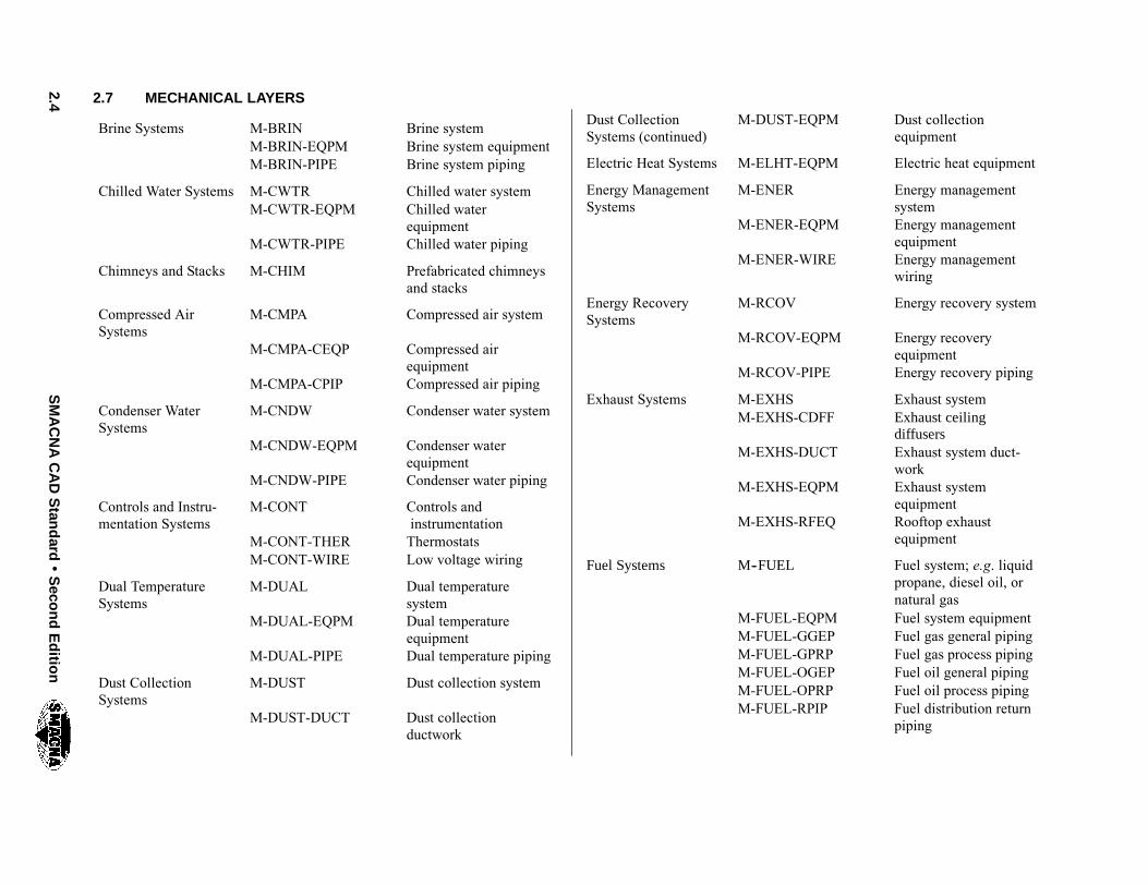
2.7 MECHANICAL LAYERS
Brine Systems M-BRIN Brine systemM-BRIN-EQPM Brine system equipmentM-BRIN-PIPE Brine system piping
Chilled Water Systems M-CWTR Chilled water systemM-CWTR-EQPM Chilled water
equipmentM-CWTR-PIPE Chilled water piping
Chimneys and Stacks M-CHIM Prefabricated chimneysand stacks
Compressed AirSystems
M-CMPA Compressed air system
M-CMPA-CEQP Compressed airequipment
M-CMPA-CPIP Compressed air piping
Condenser WaterSystems
M-CNDW Condenser water system
M-CNDW-EQPM Condenser waterequipment
M-CNDW-PIPE Condenser water piping
Controls and Instru-mentation Systems
M-CONT Controls andinstrumentation
M-CONT-THER ThermostatsM-CONT-WIRE Low voltage wiring
Dual TemperatureSystems
M-DUAL Dual temperaturesystem
M-DUAL-EQPM Dual temperatureequipment
M-DUAL-PIPE Dual temperature piping
Dust CollectionSystems
M-DUST Dust collection system
M-DUST-DUCT Dust collectionductwork
Dust CollectionSystems (continued)
M-DUST-EQPM Dust collectionequipment
Electric Heat Systems M-ELHT-EQPM Electric heat equipment
Energy ManagementSystems
M-ENER Energy managementsystem
M-ENER-EQPM Energy managementequipment
M-ENER-WIRE Energy managementwiring
Energy RecoverySystems
M-RCOV Energy recovery system
M-RCOV-EQPM Energy recoveryequipment
M-RCOV-PIPE Energy recovery piping
Exhaust Systems M-EXHS Exhaust systemM-EXHS-CDFF Exhaust ceiling
diffusersM-EXHS-DUCT Exhaust system duct-
workM-EXHS-EQPM Exhaust system
equipmentM-EXHS-RFEQ Rooftop exhaust
equipment
Fuel Systems M--FUEL Fuel system; e.g. liquidpropane, diesel oil, ornatural gas
M-FUEL-EQPM Fuel system equipmentM-FUEL-GGEP Fuel gas general pipingM-FUEL-GPRP Fuel gas process pipingM-FUEL-OGEP Fuel oil general pipingM-FUEL-OPRP Fuel oil process pipingM-FUEL-RPIP Fuel distribution return
piping
2.5S
MA
CN
AC
AD
Stan
dard
S
econ
dE
ditio
n
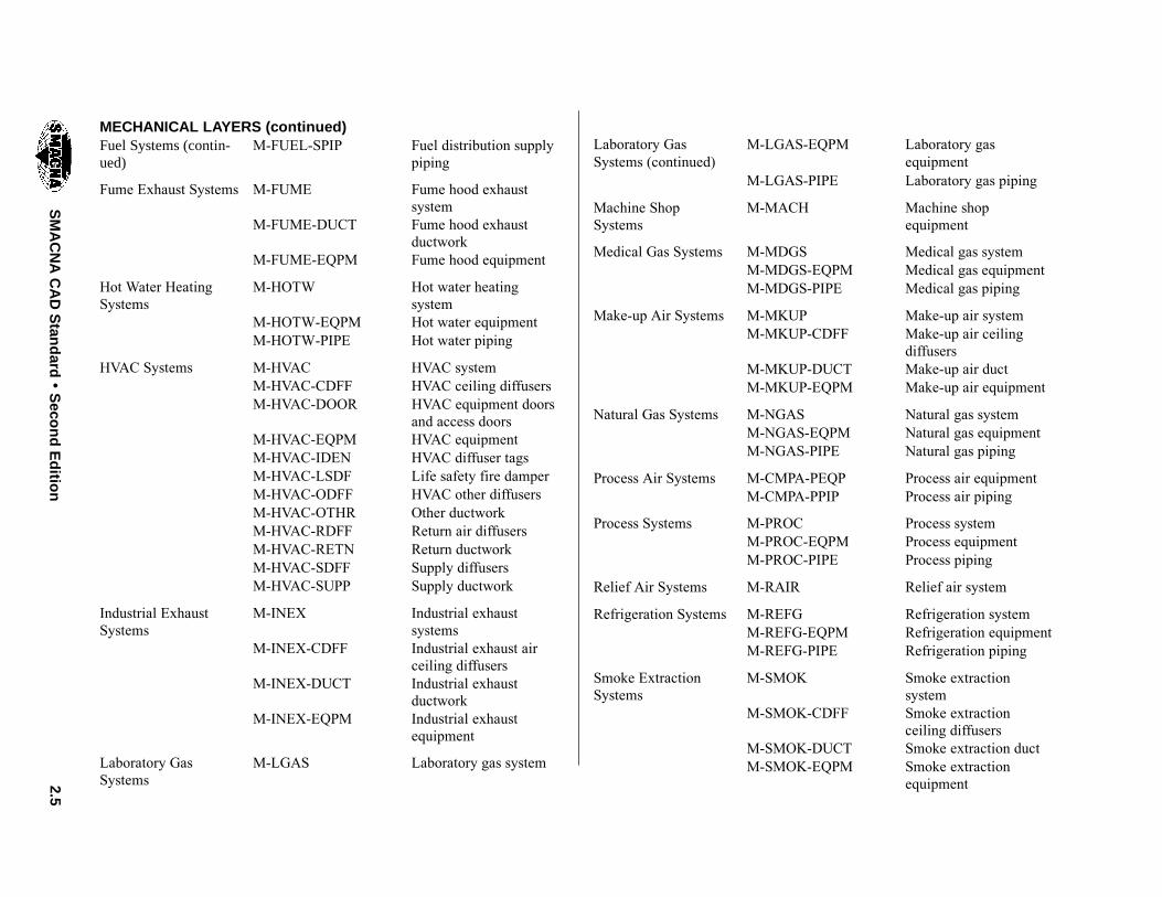
MECHANICAL LAYERS (continued)Fuel Systems (contin-ued)
M-FUEL-SPIP Fuel distribution supplypiping
Fume Exhaust Systems M-FUME Fume hood exhaustsystem
M-FUME-DUCT Fume hood exhaustductwork
M-FUME-EQPM Fume hood equipment
Hot Water HeatingSystems
M-HOTW Hot water heatingsystem
M-HOTW-EQPM Hot water equipmentM-HOTW-PIPE Hot water piping
HVAC Systems M-HVAC HVAC systemM-HVAC-CDFF HVAC ceiling diffusersM-HVAC-DOOR HVAC equipment doors
and access doorsM-HVAC-EQPM HVAC equipmentM-HVAC-IDEN HVAC diffuser tagsM-HVAC-LSDF Life safety fire damperM-HVAC-ODFF HVAC other diffusersM-HVAC-OTHR Other ductworkM-HVAC-RDFF Return air diffusersM-HVAC-RETN Return ductworkM-HVAC-SDFF Supply diffusersM-HVAC-SUPP Supply ductwork
Industrial ExhaustSystems
M-INEX Industrial exhaustsystems
M-INEX-CDFF Industrial exhaust airceiling diffusers
M-INEX-DUCT Industrial exhaustductwork
M-INEX-EQPM Industrial exhaustequipment
Laboratory GasSystems
M-LGAS Laboratory gas system
Laboratory GasSystems (continued)
M-LGAS-EQPM Laboratory gasequipment
M-LGAS-PIPE Laboratory gas piping
Machine ShopSystems
M-MACH Machine shopequipment
Medical Gas Systems M-MDGS Medical gas systemM-MDGS-EQPM Medical gas equipmentM-MDGS-PIPE Medical gas piping
Make-up Air Systems M-MKUP Make-up air systemM-MKUP-CDFF Make-up air ceiling
diffusersM-MKUP-DUCT Make-up air ductM-MKUP-EQPM Make-up air equipment
Natural Gas Systems M-NGAS Natural gas systemM-NGAS-EQPM Natural gas equipmentM-NGAS-PIPE Natural gas piping
Process Air Systems M-CMPA-PEQP Process air equipmentM-CMPA-PPIP Process air piping
Process Systems M-PROC Process systemM-PROC-EQPM Process equipmentM-PROC-PIPE Process piping
Relief Air Systems M-RAIR Relief air system
Refrigeration Systems M-REFG Refrigeration systemM-REFG-EQPM Refrigeration equipmentM-REFG-PIPE Refrigeration piping
Smoke ExtractionSystems
M-SMOK Smoke extractionsystem
M-SMOK-CDFF Smoke extractionceiling diffusers
M-SMOK-DUCT Smoke extraction ductM-SMOK-EQPM Smoke extraction
equipment

2.6S
MA
CN
AC
AD
Stan
dard
S
econ
dE
ditio
n
MECHANICAL LAYERS (continuted)
Special MechanicalSystems
M-SPCL Special system
M-SPCL-EQPM Special systemequipment
M-SPCL-PIPE Special system piping
Test Equipment M-TEST Test equipment
Steam Systems M-STEM Steam systemM-STEM-CONP Steam condensate
pipingM-STEM-EQPM Steam equipmentM-STEM-HPIP High pressure steam
pipingM-STEM-LPIP Low pressure steam
pipingM-STEM-MPIP Medium pressure steam
piping
2.7S
MA
CN
AC
AD
Stan
dard
S
econ
dE
ditio
n
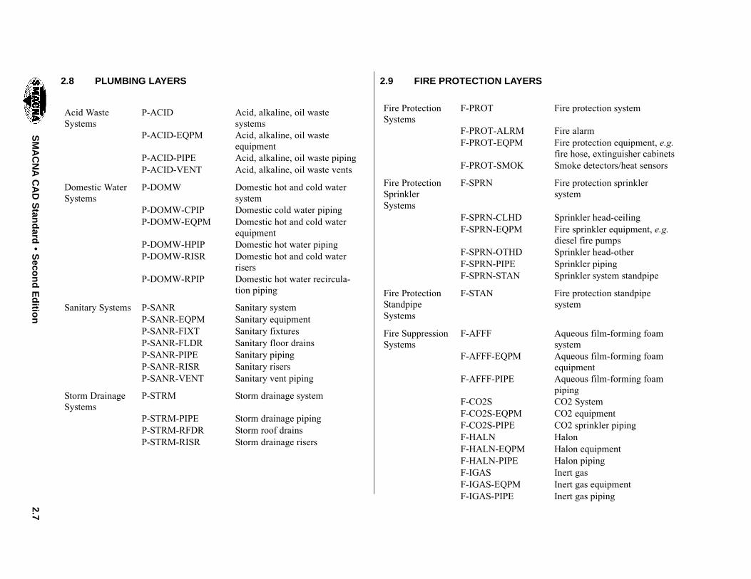
2.8 PLUMBING LAYERS
Acid WasteSystems
P-ACID Acid, alkaline, oil wastesystems
P-ACID-EQPM Acid, alkaline, oil wasteequipment
P-ACID-PIPE Acid, alkaline, oil waste pipingP-ACID-VENT Acid, alkaline, oil waste vents
Domestic WaterSystems
P-DOMW Domestic hot and cold watersystem
P-DOMW-CPIP Domestic cold water pipingP-DOMW-EQPM Domestic hot and cold water
equipmentP-DOMW-HPIP Domestic hot water pipingP-DOMW-RISR Domestic hot and cold water
risersP-DOMW-RPIP Domestic hot water recircula-
tion piping
Sanitary Systems P-SANR Sanitary systemP-SANR-EQPM Sanitary equipmentP-SANR-FIXT Sanitary fixturesP-SANR-FLDR Sanitary floor drainsP-SANR-PIPE Sanitary pipingP-SANR-RISR Sanitary risersP-SANR-VENT Sanitary vent piping
Storm DrainageSystems
P-STRM Storm drainage system
P-STRM-PIPE Storm drainage pipingP-STRM-RFDR Storm roof drainsP-STRM-RISR Storm drainage risers
2.9 FIRE PROTECTION LAYERS
Fire ProtectionSystems
F-PROT Fire protection system
F-PROT-ALRM Fire alarmF-PROT-EQPM Fire protection equipment, e.g.
fire hose, extinguisher cabinetsF-PROT-SMOK Smoke detectors/heat sensors
Fire ProtectionSprinklerSystems
F-SPRN Fire protection sprinklersystem
F-SPRN-CLHD Sprinkler head-ceilingF-SPRN-EQPM Fire sprinkler equipment, e.g.
diesel fire pumpsF-SPRN-OTHD Sprinkler head-otherF-SPRN-PIPE Sprinkler pipingF-SPRN-STAN Sprinkler system standpipe
Fire ProtectionStandpipeSystems
F-STAN Fire protection standpipesystem
Fire SuppressionSystems
F-AFFF Aqueous film-forming foamsystem
F-AFFF-EQPM Aqueous film-forming foamequipment
F-AFFF-PIPE Aqueous film-forming foampiping
F-CO2S CO2 SystemF-CO2S-EQPM CO2 equipmentF-CO2S-PIPE CO2 sprinkler pipingF-HALN HalonF-HALN-EQPM Halon equipmentF-HALN-PIPE Halon pipingF-IGAS Inert gasF-IGAS-EQPM Inert gas equipmentF-IGAS-PIPE Inert gas piping
2.8 SMACNA CAD Standard Second Edition
2.10 DRAWING VIEW LAYER LIST
When organizing layers by drawing type, the NCS 2.0provides for the creation of Drawing View GroupsDETL, ELEV, and SECT. This four character fieldmay be used as a major group, a minor group, or as aminor group modifier, e.g. it may be used to modifyany building system major group, such as: M-HVAC-DETL, etc. To remain in compliance with SCS andNCS 2.0, do not exceed the maximum number of layername characters defined in section 2.5.
An optional field, ANNN, used exclusively as a modi-fier toDrawingViewGroups, provides amore detailedmeans of structuring or cataloging drawings. It con-sists of a four character wide field, where the first char-acter is alphabetic and the last three characters are nu-meric, e.g. A001, B102, etc. To provide for maximumflexibility, the meaning of this layer group is user de-fined. It is strongly recommended that the preciseusage (definition) of these layers, be documented andsubmitted with each set of drawings where it is used.
Note that the minor group fields used in the examplesbelow, MCUT, MBND, PATT, IDEN, and OTLNmaybe used to modify any major or minor group.
*-DETL Detail Drawing View
*-ELEV Elevation Drawing View
*-SECT Section Drawing View
*-****-ANNN Drawing View—Optional Number
*-****-ANNN-MCUT Drawing View—OptionalNumber—Material Cut
*-****-ANNN-MBND Drawing View—OptionalNumber—MaterialBeyond Cut
*-****-ANNN-PATT Drawing View—OptionalNumber—Textures andHatch Patterns
*-****-ANNN-IDEN Drawing View—OptionalNumber—ComponentIdentification Number
*-****-ANNN-OTLN Drawing View—OptionalNumber—Outline ofObject Drawn
2.11 THREE DIMENSIONAL DRAWINGS
Three-dimensional drawings provide tremendous de-sign and construction advantages. Since building amodel is just like real construction, it helps tremen-dously if building system components are organizedinto building system layers. Selectively turning ononly the required building system component layershelps you to see what you are doing and it speeds upthe whole modeling process. Being able to isolate lay-ers by building system helps to identify interferenceproblems between building system components wellbefore they become expensive construction errors inthe field. Both the NCS and SCS layering guidelinessupport this modeling process very well.
To separate 2D from 3D building system components,the NCS 1.0 recommended appending the modifier“ELEV” to a layer name to denote it as a three-dimen-sional drawing, e.g.
M-HVAC-RDFF Mechanical—HVAC—Return Air Diffuser (twodimensional)
M-HVAC-RDFF-ELEV Mechanical-HVAC-Return Air Diffuser—ELEV (three dimensional)
Sorting two dimensional components from three di-mensional components by layer is often no longer nec-essary today, because CAD systems are nowmore ob-ject oriented and integrated. To display a two orthree-dimensional view no longer requires layers to beturned on and off. Instead, the orientation of themodelview is altered to change its perspective.
Legacy CAD systems can provide challenges whensharing files between disciplines. 3D file sizes can bequite large and containmore information than a file re-cipient needs; sometimes overwhelming the computa-tional power of existing computer equipment. Plan-ning is required to transmit only the information thatis required. The recipient of such files needs to ensurethat their hardware and software are sufficient to pro-cess the files. Running system compatibility tests is es-sential before entering into a contractual agreementand commencing with work.
2.12 ANNOTATION LAYERS
Annotation is the only major group that is not a build-ing system. Since annotation is required to describebuilding system components in several distinct ways,annotation is assigned its own set of unique layers.This is also useful, because annotation can interfere
2.9SMACNA CAD Standard Second Edition
with precise drafting, offering a multitude of erro-neous snap coordinates. Generally, drawings can beedited faster if annotation is placed on separate layerswhere it can be turned on and off as needed. Currently,the NCS 2.0 annotation layer guidelines state:
Annotation consists of text, dimensions, notes, sheetborders, detail references and other elements onCAD drawings that do not represent physical as-pects of a building. Use of the Major Group ANNOallows all annotation to be placed in a definedgroup of layers.
The layer names shown below encompass the com-plete list of prescribed Minor Group field codes forannotation. These Minor Groups may be used tomodify any Major or Minor Group.
*-ANNO-DIMS Dimensions
*-ANNO-KEYN Keynotes
*-****-IDEN Identification tags
*-ANNO-LABL Labels
*-ANNO-LEGN Legends and schedules
*-ANNO-MARK Elevation, section, detail,and break marks & lead-ers
*-ANNO-MATC Match lines
*-ANNO-NOTE Notes
*-ANNO-NPLT Non-plotting graphicinformation
*-****-RDME Read-me layer (notplotted)
*-ANNO-REDL Redline
*-ANNO-REFR Reference layer toexternal data files
*-ANNO-REVC Revision clouds
*-ANNO-REVS Revisions
*-ANNO-REVT Review text and triangle
*-ANNO-SCHD Schedules
*-ANNO-SYMB Symbols
*-ANNO-TABL Data tables
*-ANNO-TEXT Text
*-ANNO-TITL Drawing or detail titles
*-ANNO-TTLB Border and Title block
Above, * denotes the discipline responsible for the lay-er.
Annotation can be applied to a model via at least twotechniques.
By Reference File and Layer
To facilitate sharing of the base model among disci-plines by encouraging concurrent editing, the annota-tion for each drawing can be stored in its own separatedrawing file. For example, to generate a plotted sheetof a plan drawing, at lease three separate drawing filesare combined:
S A base architecture plan drawing file;
S A discipline overlay drawing file includingboth building system and annotation layers;and
S A sheet title block overlay drawing file thatframes the base architecture and disciplineoverlay files.
By Layer Only
Separating annotation into reference files can becumbersome for smaller projects. Sometimes it ismore efficient to combine the annotation for severaldifferent drawings into a single drawing file. Usingscripts or saved sheet layouts, sets of layers can beturned on and off automatically to display several dif-ferent drawings complete with their own annotation,without the additional steps of opening and closing fi-les. To separate one drawing’s set of annotation fromanother, a separate set of annotation layers is requiredfor each. Each set of drawing annotation can beuniquely identified by appending an annotation minorgroup as modifier to a major group or a minor group,e.g.
M-HVAC-TEXT denotes the text annota-tion for the HVAC draw-ing;

2.10 SMACNA CAD Standard Second Edition
M-HVAC-EQPM-TEXT denotes the text annota-tion for the HVACequipment drawing.
Note that using annotation groups in this manner pre-cludes the use of the second minor modifier field forany other purpose for a given layer, e.g. you could notcreate a layer for text annotation describing floormounted HVAC equipment. The layer name“M-HVAC-EQPM-FLOR-TEXT” would exceed thelength of the layer name permitted by NCS.
2.13 SAMPLE DRAWING ORGANIZATION
A small new construction project might contain onlythe following layers:
2.13.1 Base Architecture File
A-WALL Architecture—Walls
A-DOOR Architecture—Door
A-FLOR-CASE Architecture—Floor—Casework
A-FLOR-EVTR Architecture—Floor—Elevators
A-FLOR-STRS Architecture—Floor—Stairs
A-FLOR-PFIX Architecture—Floor—Plumbing Fixtures
S-COLS Structure—Columns
S-GRID Column Grid
I-WALL Interior—Walls
I-DOOR Interior—Doors
2.13.2 Mechanical Discipline File
M-HVAC-CDFF HVAC ceiling diffusers
M-HVAC-DOOR HVAC equipment doors
M-HVAC-EQPM HVAC equipment
M-HVAC-IDEN HVAC diffuser tags
M-HVAC-OTHR Other ductwork
M-HVAC-RETN Return ductwork
M-HVAC-SUPP Supply ductwork
M-ANNO-DIMS Dimensions
M-ANNO-KEYN Keynotes
M-ANNO-LEGN Legends and schedules
M-ANNO-NOTE Notes
M-ANNO-NPLT Nonplotting Constructionlines
M-ANNO-REDL Redline
Base Architecture
Discipline Overlay
Title Block Overlay

2.11SMACNA CAD Standard Second Edition
M-ANNO-REVS Revisions
M-ANNO-SYMB Symbols
M-ANNO-TEXT Text
2.13.3 Title Block File
M-ANNO-TTLB Border and Title block
A renovation project of any size requires a longer listof layers denoting construction status. For each of thebuilding system component layers listed above, threelayers are required denoting construction status, e.g.
M-HVAC-RDFF-E Return air diffusers -Existing to Remain
M-HVAC-RDFF-D Return air diffusers -Existing to Demolish
M-HVAC-RDFF-N Return air diffusers—NewWork
2.14 ANNOTATION LAYERS ANDINTERNATIONAL STANDARDS
The NCS CAD Layer Guidelines are a standard thatworkswell within the United States, but differences doexist between this national standard and the Interna-tional Standards Organization layer standard devel-oped and adopted by 14 countries including the UnitedStates. Unfortunately, the manner in which the NCSstandard defines annotation is not in compliance withthe ISO. The full ISO layer standard structure is as fol-lows:
The first three fields are mandatory and the remainingsix fields are optional. The first three fields are themost important for this discussion. The ISO’s Agent
B101 RC
Agent ResponsibleElementPresentation
StatusSectorPhaseProjectionScaleWork Package
A1 B210__ D_ N F3 1
Responsible field corresponds to the NCS’sDisciplinefield. The ISO’s Element field corresponds to theNCS’sMajor Group field. The third ISO field, Presen-tation, the annotation field, is the source of the pro-blem. The ISOhas chosen to associate annotationwitheach building system while NCS has defined annota-tion as a major group. These standards are in directconflict and pose difficulty for any United States firmtrying to comply with the NCS standard while doingwork overseas.
Recently, NCS has readopted the use of an additionalminor group modifier, enabling the annotation fieldsto be appended to a layer root name defined by its dis-cipline and major group fields. For example, annota-tion layers for HVAC plans can result in layers like:
M-HOTW-EQPM-TEXT,M-HOTW-PIPE-TEXT,M-HVAC-EQPM-TEXT, etc.
By employing this method, NCS standard layers canmap on a one-to-one basis with ISO standard layers,thus enabling compliance with both NCS and ISOstandards.

2.12 SMACNA CAD Standard Second Edition
THIS PAGE INTENTIONALLY LEFT BLANK

CHAPTER 3
ABBREVIATIONS


ABBREVIATIONSCHAPTER 3
3.1SMACNA CAD Standard Second Edition
ABBREVIATIONS / DESCRIPTIONS
The following list of abbreviations is commonly usedto describe the referenced item. For a more extensivelisting of abbreviations, including those for disciplinesnot normally associated with HVAC, see SectionUDS-05 Terms and Abbreviations of the NationalCADStandard. The abbreviations and descriptions areas follows:
3.1 A
AAD Automatic air damperAAV Automatic air ventABS AbsoluteABSORB AbsorptionACCU Air Cooled Condensing UnitACID RES Acid resistantACID RES CI Acid resistant cast ironACID RES P Acid resistant pipeACID RES V Acid resistant ventACID RES W Acid resistant wasteACCUM AccumulatorACP Automatic Control PanelACS Automatic Control SystemA/C Air ConditioningACU Air Conditioning UnitACV Automatic Control ValveAC Alternating CurrentAD Access Door, Area DrainADA American Disabilities ActADD AdditionADJ AdjustableADP Apparatus Dew PointAE Anesthesia EvacuationAFF Above Finished FloorAFMS Air Flow Measuring StationAHP Air HorsepowerAHU Air Handling UnitALT Altitude, AlternateAMB AmbientAMP Ampere (Amp, Amps)ANSI American National Standards
InstituteAP, ACS PNL Access Panel
APD Air Pressure DropAPPROX Approximat(e), (ely)AR Air Relief, As RequiredARCH ArchitectARV Air Relief ValveAS Air SeparatorASU Air Supply UnitASV Angle Stop ValveATM AtmosphereAV Acid Vent, Air VentAVG AverageAW Acid WasteAWG American Wire GaugeAX FL Axial Flow
3.2 B
B&S Brown & Sharp Wire Gauge, Bell& Spigot
BAL BalanceBAPR Barometric PressureBARO BarometerBBD Boiler Blow DownBBR Baseboard radiatorBCV Butterfly Check ValveBD Butterfly DamperBDD Backdraft DamperBFP Backflow PreventerBFV Butterfly ValveBFW Boiler Feed WaterBFWP Boiler Feed Water PumpBHP Brake HorsepowerBLDG BuildingBLO BlowerBLR BoilerBLR HP Boiler HorsepowerBOM Bill of MaterialBP Boiling PointBSP Black Steel PipeBT Bath TubBOT BottomBTU British Thermal UnitBV Ball ValveBYP By Pass
3.3 C
CA Compressed AirCAV Constant Air Volume

3.2 SMACNA CAD Standard Second Edition
C/C, CC Cooling CoilCCW Counter ClockwiseCD Condensate Drain, Ceiling
DiffuserCDW Chilled Drinking WaterCDWR Chilled Drinking Water ReturnCDWS Chilled Drinking Water SupplyCFM Cubic Feet per MinuteCFOI Contractor Furnished/Owner
InstalledCFS Cubic Feet Per SecondCH ChillerCHCF Chilled Water Chemical FeedCHKV Check ValveCHWM Chilled Water Make-upCHWP Chilled Water PumpCHWPP Chilled Water Primary PumpCHWR Chilled Water ReturnCHWRP Chilled Water Recirculating PumpCHWS Chilled Water SupplyCHWSP Chilled Water Secondary PumpCI Cast IronCIP Cast Iron PipeCISP Cast Iron Soil PipeCKT CircuitCLG CeilingCLG DIFF Ceiling DiffuserCLG GRL Ceiling GrilleCLG HT Ceiling HeightCLG REG Ceiling RegisterCW ClockwiseCO Clean OutCO2 Carbon DioxideCOEFF CoefficientCOL ColumnCOMP CompressorCONC ConcreteCOND Condens(er), (ing), (ation),
ConditionCONST ConstructionCONT Continuou(s), (e)CONV ConvectorCOP Coefficient of Performance
(Heating), CopperCOTG Cleanout to GradeCCP Cooling Coil PumpCP Condensate Pump
CPD Condensate Pump DischargeCPLG CouplingCR Control RelayCRP Condensate Return PumpCSG CasingCT Cooling TowerCTR Cooling Tower ReturnCTS Cooling Tower SupplyCU Condensing UnitCV Control ValveCU FT Cubic FeetCU IN Cubic InchesCU YD Cubic YardCUH Cabinet Unit HeaterCW Cold WaterCWCF Condenser Water Chemical FeedCWP Condenser Water PumpCWR Condenser Water ReturnCWS Condenser Water Supply
3.4 D
DA Dental AirDAP Duct Access PaneldB Decibel(s)DB Dry Bulb TemperatureDC Direct CurrentDCI Duct Covering InsulationDDC Direct Digital ControlDEG DegreeDENS DensityDEPT DepartmentDF Drinking FountainDH Duct HeaterDIW De-ionized WaterDIA DiameterDIP Ductile Iron PipeDISCH DischargeDLI Duct Liner InsulationDMPR DamperDP DewpointDPS Differential Pressure SensorDPT Dew Point TemperatureDR DrainDS DownspoutDST Daylight Savings Time

3.3SMACNA CAD Standard Second Edition
DT Delta TemperatureDUC Door UndercutDW Distilled WaterDWG DrawingDWV Drain, Waste, and Vent
3.5 E
EAG, EXH GR Exhaust Air GrilleEAR Exhaust Air RegisterEAT Entering Air TemperatureEBB Electric Base BoardEC Electrical Contractor, Edge of
CurbECC RDCR Eccentric ReducerECON EconomizerECU Evaporative Cooling UnitECWR Equipment Cooling Water ReturnECWS Equipment Cooling Water SupplyEDBT Entering Dry Bulb TemperatureEDH Electric Duct HeaterEDR Equivalent Direct RadiationEER Energy Efficiency RatioEF, EXH FN Exhaust FanEFF EfficiencyEHP Electric Heating PanelEL ElevationELEC ElectricELEV ElevatorEMER EmergencyEMER SHR Emergency ShowerEMF Electromotive ForceEM ElectromagneticENCL EnclosureENG English UnitsENT EnteringEOM End of MainEOV Electrically Operated ValveEPRF Explosion ProofEQIV FT Equivalent FeetEQIV IN Equivalent InchesEQUIP EquipmentERD Existing Roof DrainESC Escutcheon, EscapeESP External Static PressureEST Eastern Standard Time
ET Expansion TankEUH, EH Electric (Unit) HeaterEVAP Evaporat(e), (ing), (ed), (or)EWS Eye Wash StationEWC Electric Water CoolerEWBT Entering Wet Bulb TemperatureEWH Electric Water HeaterEWT Entering Water TemperatureEXCH ExchangerEXH ExhaustEXH A Exhaust AirEXH DT Exhaust DuctEXH FN Exhaust FanEXH GR Exhaust Air GrilleEXH HD Exhaust HoodEXHV Exhaust VentEXIST ExistingEXP ExpansionEXT Exterior
3.6 F
F FahrenheitF&B Face and By-passF&T Float and Thermostatic TrapFA Face AreaFAG Forced Air Gas (Furnace)FAI Flexible Air IntakeFC Flexible ConnectionFCO Floor CleanoutFCU Fan Coil UnitFD Floor Drain, Fire DamperFDC Fire Department Connection,
Flexible Duct ConnectionFF Final FiltersFFA From Floor AboveFFB From Floor BelowFH Fire HoseFHC Fire Hose CabinetFIN FinishFIXT FixtureFLEX FlexibleFLR FloorFL SW Flow SwitchFLR REG Floor RegisterFLR SK Floor Sink

3.4 SMACNA CAD Standard Second Edition
FLTR FilterFO Fuel OilFOP Fuel Oil PumpFOR Fuel Oil ReturnFOS Fuel Oil SupplyFOV Fuel Oil VentFP Fire ProtectionFPC Fire Protection ContractorFPCV Fan Powered Constant VolumeFPT Fan Powered TerminalFTLB Foot PoundFPM Feet per MinuteFPS Feet per SecondFPVAV Fan Powered Variable Air VolumeFRP Fiberglass Reinforced PlasticFSD Fire Smoke DamperFSS Flow Sensing SwitchFSTAT FreezestatFTG FootingFURN Furnace, Furnish, FurnitureFUS LINK Fusible LinkFWR Filter Water ReturnFWS Filter Water SupplyFV Face Velocity
3.7 G
G Natural GasG LN Gas LineGA GageGAL GallonGALV GalvanizedGC General ContractorGPD Gallon per DayGPH Gallon per HourGPM Gallon per MinuteGPS Gallon per SecondGR Glycol ReturnGS Glycol SupplyGT Grease TrapGTD Greatest Temperature Difference
3.8 H
HB Hose BibHC Hose ClosetHCP Heating Coil Pump (Hot Water)HD HeadHE HeliumHEPA High Efficiency Particulate Air
(Filter)HEX Heat ExchangerHG Heat Gain or MercuryHO Hub OutletHOA Hand, Off, Auto StationHORIZ HorizontalHOSP HospitalHP Horsepower, Heat PumpHPB High Pressure BoilerHPDT High Pressure Drip TrapHPR High Pressure Condensate ReturnHPS High Pressure SteamHPT High Pressure TrapHR HourHS Hand SinkHSTAT HumidistatHT HeightHTHW High Temperature Hot WaterHTR HeaterHVAC Heating, Ventilating, and Air
ConditioningHVD High Velocity DiffuserHVT High Velocity TerminalHW Hot WaterHWB Hot Water BoilerHWC Hot Water CoilHWCP Hot Water Circulating PumpHWP Hot Water PumpHWR Hot Water ReturnHWS Hot Water SupplyHWT Hot Water TankHWCF Heating Water Chemical FeedHTWR Heating Water ReturnHTWS Heating Water SupplyHZ Frequency
3.5SMACNA CAD Standard Second Edition
3.9 I
IAQ Indoor Air QualityID Inside DiameterIF Intake FanIHP Indicated HorsepowerIN WC Inches, Water ColumnINCIN IncineratorINCL IncludeINSTR InstrumentINSUL Insulat(e), (ed), (ion)INT InteriorINV InvertI/O Input/OutputIP Iron PipeIPS International Pipe StandardIPT Iron Pipe ThreadedIWH Instantaneous Water Heater
3.10 J
JS Janitor’s SinkJT Joint
3.11 K
K Thermal Conductivity, KelvinKEC Kitchen Equipment ContractorKIP Thousand PoundsKW KilowattKWH Kilowatt Hour
3.12 L
LA Laboratory AirLAB LaboratoryLAD Laminar Air DiffuserLAF Laminar Air FlowLAP Low Ambient ProtectionLAT Leaving Air TemperatureLATR LateralLAV LavatoryLB PoundLCD Linear Ceiling DiffuserLD Linear Diffuser
LDBT Leaving Dry Bulb TemperatureLEN LengthLF Linear FeetLFD Laminar Flow DiffuserLG Liquid GasLH Latent HeatLHG Latent Heat GainLHR Latent Heat RatioLIQ LiquidLMTD Least Mean Temperature
DifferenceLN Liquid NitrogenLNG Liquid Natural GasLO Lubricating OilLOC LocationLOG LogarithmLOP Lubricating Oil PumpLOV Lubricating Oil VentLOX Liquid OxygenLP Low PressureLPG Liquified Petroleum GasLPAS Low Pressure Alarm SwitchLPB Low Pressure BoilerLPCR Low Pressure Condensate ReturnLPDT Lower Pressure Drip TrapLPL Lightproof LouverLPR Low Pressure ReturnLPS Low Pressure SteamLPV Light Proof VentLTD Least Temperature DifferenceLTHW Low Temperature Hot WaterLV Laboratory VacuumLVR LouverLWBT Leaving Wet Bulb TemperatureLWCO Low Water Cut OffLWT Leaving Water Temperature
3.13 M
MA Medical Air, Mixed AirMACH Mach NumberMAT Mixed Air TemperatureMAU, MAHU Make Up Air Handling UnitMAV Manual Air VentMAX MaximumMB Mop Basin, Mixing BoxMBH BTU/Hr x 1,000,000

3.6 SMACNA CAD Standard Second Edition
MC Mechanical ContractorMD Manual DamperMECH MechanicalMED VAC Medium VacuumMET Mean Effective TemperatureMFR Mass Flow RateMH Man HoleMIN MinimumMISC MiscellaneousMOD Motor Operated DamperMOV Motor Operated ValveMP Medium PressureMPG Medium Pressure GasMPH Miles Per HourMPR Medium Pressure Condensate
(Return)MPS Medium Pressure SteamMPT Male Pipe ThreadMTD Mounted, Mean Temperature
DifferenceMTHW Medium Temperature Hot WaterMTL MetalMVD Manual Volume DamperMZ Multizone
3.14 N
N NitrogenNA Not ApplicableNC Noise Criteria, Normally ClosedNIC Not In ContractNO Nitrous Oxide, Normally OpenNO. NumberNR Noise ReductionNRC Noise Reduction CoefficientNTS Not To Scale
3.15 O
O OxygenOA Outside AirOAD Outside Air DamperOAG Outside Air GrilleOAI Outside Air IntakeOAT Outside Air TemperatureOBD Opposed Blade Damper
OD Outside DiameterOF/CI Owner Furnished/Contractor
InstalledOFD Overflow DrainOF/OI Owner Furnished/Owner InstalledOPNG OpeningOSD Open Sight DrainOSL Oil SealOSP Operating Steam PressureOS&Y Open Screw & YokeOUT OutletOZ Ounce
3.16 P
P PumpPA Pipe AnchorPCC Precool CoilPCD Polyvinyl Coated DuctPCT PercentPCWR Panel Chilled Water ReturnPCWS Panel Chilled Water SupplyPD Pressure Drop/DifferencePDISCH Pump DischargePE Pneumatic ElectricPETRO PetroleumPF Pre-FilterPH Phase (electric)PHC Preheat CoilPHWR Perimeter Heating Hot Water
ReturnPHWS Perimeter Heating Hot Water
SupplyPIV Post Indicator ValvePLMB PlumbingPLT Plaster TrapPMPSCT Pump SuctionPOC Point of ConnectionPPM Parts per MillionPR Pumped ReturnPRE Power Roof ExhaustPREFAB Pre-FabricatedPRES PressurePRESS SW Pressure SwitchPRI PrimaryPRS Pressure Reducing StationPRV Pressure Reducing Valve, Power
Roof Ventilator

3.7SMACNA CAD Standard Second Edition
PSF Pounds per Square FootPSI Pounds per Square InchPSIA Pounds Per Square Inch, AbsolutePSIG Pounds per Square Inch GagePSL Pipe SleevePT Pneumatic TubePTAC Packaged Terminal Air
ConditionerPTS Pneumatic Tube StationPVC Polyvinyl Chloride
3.17 Q
QT QuartQTY Quantity
3.18 R
R Thermal Resistance, RankineRFGT RefrigerantR12 Refrigerant 12R22 Refrigerant 22RA Return AirRAD Radiat(e), (or), (ion)RAF, RA FAN Return Air FanRA GR Return Air GrilleRAC Room Air ConditionerRAD Return Air DuctRAT Return Air TemperatureRCP Reinforced Concrete PipeRD Roof DrainREC ReceiverRECIRC Recirculat(e), (or), (ing)RDC ReducerREF RefrigeratorREFR RefrigerationREG RegisterRES ResistanceRFGT RefrigerantRAG Return Air GrilleRH Relative HumidityRHC Reheat CoilRHG Refrigerant Hot GasRHV Reheat ValveRL Refrigerant LiquidRLL Refrigerant Liquid Line
RM RoomROW Reverse Osmosis WaterRP Radiant PanelRPM Revolutions per MinuteRPS Revolutions per SecondRS Refrigerant SectionRSC Rotary Screw CompressorRSL Refrigerant Suction LineRTU Roof Top UnitREV Revolutions, Revision, and
ReverseRV Relief Valve
3.19 S
SA Supply AirSAF Supply Air FanSAN SanitarySAT SaturatedSB Sitz BathSCC Steam Condensate CoolerSCFM Standard Cubic Feet per MinuteSCFS Standard Cubic Feet per SecondSCW Soft Cold Water (Domestic)SD Supply DiffuserSDMPR Smoke DamperSEC Second(s)SECT SectionSF Safety FactorSAG Supply GrilleSG Steam Gage, Specific GravitySP GR Specific GravitySH Sensible HeatSHG Sensible Heat GainSHP Shaft HorsepowerSHR Sensible Heat RatioSHR HD Shower HeadSHR DR Shower DrainSHT SheetSHW Soft Hot Water (Domestic)SVOL Secondary Hot Water ReturnSHWS Secondary Hot Water SupplySJ Slip JointSK SinkSL Sea LevelSLVT SolventSMK Smoke

3.8 SMACNA CAD Standard Second Edition
SMP Sump PumpSOLV Solenoid ValveSOV Shut Off ValveSP Sump PitSR Steam ReturnSP Static PressureSPEC SpecificationsSPG Special GasSPHT Specific HeatSVOL Specific VolumeSQ SquareSV Safety ValveSRV Safety Relief ValveSS Service Sink, Sanitary Sewer,
Standing Seam (Roof), SteamSupply, Storm Sewer, StainlessSteel
SSF Saybolt Seconds FurolSSP Stainless Steel PipeSSU Saybolt Seconds UniversalST GEN Steam GeneratorSTC Sound Transmission ClassSTD StandardSTM Steam, StormSTN StrainerSTRUCT Structur(e), (al)SU Shower UnitSTN StrainerSTP Standard Temperature and PressureSTWP Steam Working PressureSUCT SuctionSUH Suspended Unit HeaterSUPP SupplySUTK Sump TankSV Steam Vent
3.20 T
T TimeT&P VALVE Temperature and Pressure ValveT/S Tub/ShowerTAB Tabulat(e), (ion), Test Adjust &
BalanceTAG Transfer Air GrilleTB Terminal BoxTC Thermocouple
TCP Temperature Control PanelTCV Temperature Control ValveTD Temperature DifferenceTDH Total Dynamic HeadTDV Triple Duty ValveTE Temperature EnteringTEMP TemperatureTFA To Floor AboveTFB To Floor BelowTG Transfer GrilleTHK(NS) Thick(ness)TL Temperature LeavingTONS Tons of RefrigerationTSTAT ThermostatTWR Treated Water ReturnTWS Treated Water SupplyTYP Typical
3.21 U
U Heat Transfer CoefficientUC Under CutUH Unit HeaterUNO Unless Noted OtherwiseUR UrinalUV Unit Ventilator
3.22 V
V VentVA Volt AmpereVAC VacuumVAL ValveVAR VariableVAV Variable Air VolumeVB Vacuum BreakerVC Vacuum CleaningVD Vacuum Damper (Manual)VEL VelocityVENT VentilatorVERT VerticalVISC ViscosityVOL VolumeVP Pressure, Dynamic (Velocity)VPD Vacuum Pump Discharge
(Heating)

3.9SMACNA CAD Standard Second Edition
VSC Variable Speed ControllerVT Vitrified TileVTR Vent Through the RoofVUH Vertical Unit HeaterVV Vacuum VentVVT Variable Volume Terminal
3.23 W
W WasteW/ WithW/O WithoutWBT Wet Bulb TemperatureWC Water ClosetWCHR Water ChillerWCL WL MTD Water Cooler, Wall MountedWCLD Water CooledWCLR Water CoolerWCO Wall Clean Out
WF Wash FountainWH Wall HydrantWHA Water Hammer ArrestorWM Water MeterWSP Working Steam PressureWT Weight, WatertightWTR WaterWV Waste Vent
3.24 Y
YCO Yard CleanoutYD YardYR Year
3.25 Z
ZN Zone

3.10 SMACNA CAD Standard Second Edition
THIS PAGE INTENTIONALLY LEFT BLANK
CHAPTER 4
DUCT SYMBOLS

DUCT SYMBOLSCHAPTER 4
4.1SMACNA CAD Standard Second Edition
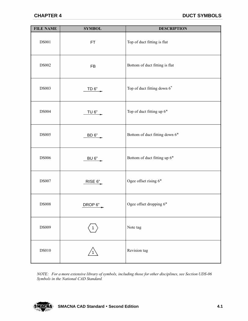
FILE NAME SYMBOL DESCRIPTION
DS001 FT Top of duct fitting is flat
DS002 FB Bottom of duct fitting is flat
DS003 TD 6” Top of duct fitting down 6"
DS004 TU 6” Top of duct fitting up 6"
DS005 BD 6” Bottom of duct fitting down 6"
DS006 BU 6” Bottom of duct fitting up 6"
DS007 RISE 6” Ogee offset rising 6"
DS008 DROP 6” Ogee offset dropping 6"
DS009 1 Note tag
DS010 1 Revision tag
NOTE: For a more extensive library of symbols, including those for other disciplines, see Section UDS-06Symbols in the National CAD Standard.

4.2 SMACNA CAD Standard Second Edition
DESCRIPTIONSYMBOLFILE NAME
DS011 2” Static pressure tag
DS012 2”1” Static pressure change tag
DS013 ROOM NAME101
Room identifier with room name and number
DS014 SP Static pressure
DS015 FC Flexible unit connection
DS016 H End of duct run with head
DS017 T Thermostat (electric)
DS018 H Humidistat (electric)
DS019 SP Static pressure sensor
DS020 SD Smoke detector

4.3SMACNA CAD Standard Second Edition
DESCRIPTIONSYMBOLFILE NAME
DS021 HD Heat detector
DS022 FS Flow switch
DS023 PS Pressure switch
DS024 T Duct thermostat
DS025 H Duct humidistat
DS026 16x12 Sheet metal duct (1st figure, side shown; 2nd figure,other side)
DS027 Direction of flow
DS028 16x12 Internally insulated sheet metal duct
DS029 (16x12) Hidden sheet metal duct
DS0309’--0”B
18x10
T 9’--10”
Duct elevation tag

4.4 SMACNA CAD Standard Second Edition
DESCRIPTIONSYMBOLFILE NAME
DS031 AD Access door or access panel (AP) in ductwork
DS032BDD
Back draft damper
DS033M
Motorized damper
DS034VD
Volume damper
DS035 SA Sound attenuator
DS036 Standard branch for supply & return (no splitter)
DS037 Wye junction
DS038 Turning vanes (rectangular)
DS039 Turning vanes (rectangular), smooth radius
DS040 Gooseneck hood (cowl)
DS041 Power or gravity roof ventilator - exhaust (ERV)
4.5SMACNA CAD Standard Second Edition
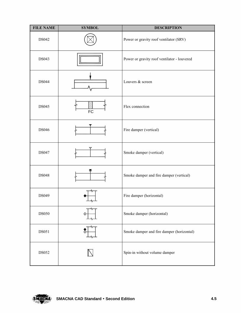
DESCRIPTIONSYMBOLFILE NAME
DS042 Power or gravity roof ventilator (SRV)
DS043 Power or gravity roof ventilator - louvered
DS044 Louvers & screen
DS045FC
Flex connection
DS046 Fire damper (vertical)
DS047 Smoke damper (vertical)
DS048 Smoke damper and fire damper (vertical)
DS049 Fire damper (horizontal)
DS050 Smoke damper (horizontal)
DS051 Smoke damper and fire damper (horizontal)
DS052 Spin-in without volume damper
4.6 SMACNA CAD Standard Second Edition
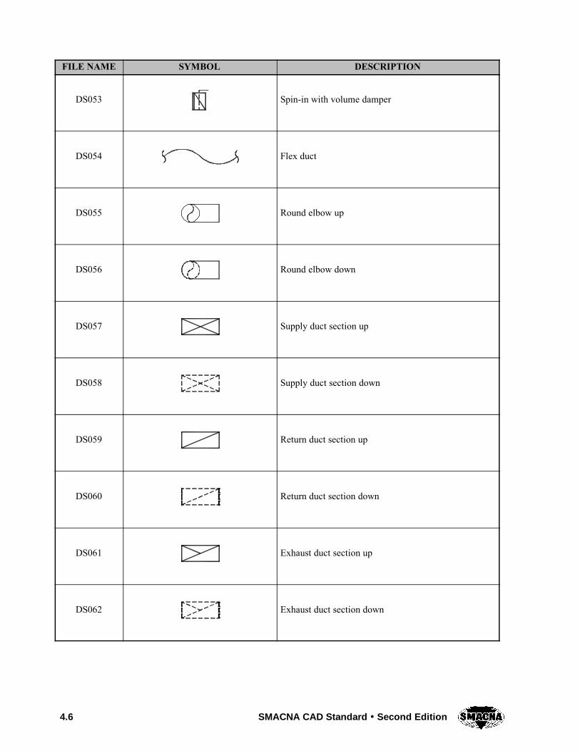
DESCRIPTIONSYMBOLFILE NAME
DS053 Spin-in with volume damper
DS054 Flex duct
DS055 Round elbow up
DS056 Round elbow down
DS057 Supply duct section up
DS058 Supply duct section down
DS059 Return duct section up
DS060 Return duct section down
DS061 Exhaust duct section up
DS062 Exhaust duct section down

4.7SMACNA CAD Standard Second Edition
DESCRIPTIONSYMBOLFILE NAME
DS063 Light troffer outlet (supply)
DS064 Light troffer inlet (return)
DS065 Side wall supply grille
DS066 Side wall return grille
DS067U
Undercut door
DS068hCFM
U Undercut door tag (h = clearance)
DS069G
Door grille
DS070CFM FA
DG Door grille tag
DS071L
Door louver
DS072CFM FA
DL Door louver tag
4.8 SMACNA CAD Standard Second Edition
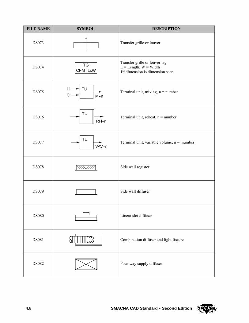
DESCRIPTIONSYMBOLFILE NAME
DS073 Transfer grille or louver
DS074 TGCFM LxW
Transfer grille or louver tagL = Length, W = Width1st dimension is dimension seen
DS075TUH
C M--nTerminal unit, mixing, n = number
DS076TU
RH--nTerminal unit, reheat, n = number
DS077TU
VAV--nTerminal unit, variable volume, n = number
DS078 Side wall register
DS079 Side wall diffuser
DS080 Linear slot diffuser
DS081 Combination diffuser and light fixture
DS082 Four-way supply diffuser

4.9SMACNA CAD Standard Second Edition
DESCRIPTIONSYMBOLFILE NAME
DS083 Three-way supply diffuser
DS084 Two-way supply diffuser
DS085 Two-way corner supply diffuser
DS086 One-way supply diffuser
DS087 Return air grille
DS088 Return air grille with sound boot
DS089 SGCFM LxW
Typical supply grille (SG), supply diffuser (SD), orsupply register (SR) tag. L = Length, W = Width

4.10 SMACNA CAD Standard Second Edition
THIS PAGE INTENTIONALLY LEFT BLANK

CHAPTER 5
EQUIPMENT SYMBOLS


EQUIPMENT SYMBOLSCHAPTER 5
5.1SMACNA CAD Standard Second Edition
FILE NAME SYMBOL DESCRIPTION
ES001 Chiller
ES002 Pump
ES003 Converter or heat exchanger shell and tube
ES004 Plate heat exchanger
ES005 Cooling tower
ES006 (NAME)Boiler, air handling unit, water source heat pump(WSHP), etc.
ES007 Unit heater (see Chapter 4 Duct Symbols for otherterminal units)
ES008 Centrifugal fan
NOTE: For a more extensive library of symbols, including those for other disciplines, see Section UDS-06Symbols in the National CAD Standard.
5.2 SMACNA CAD Standard Second Edition
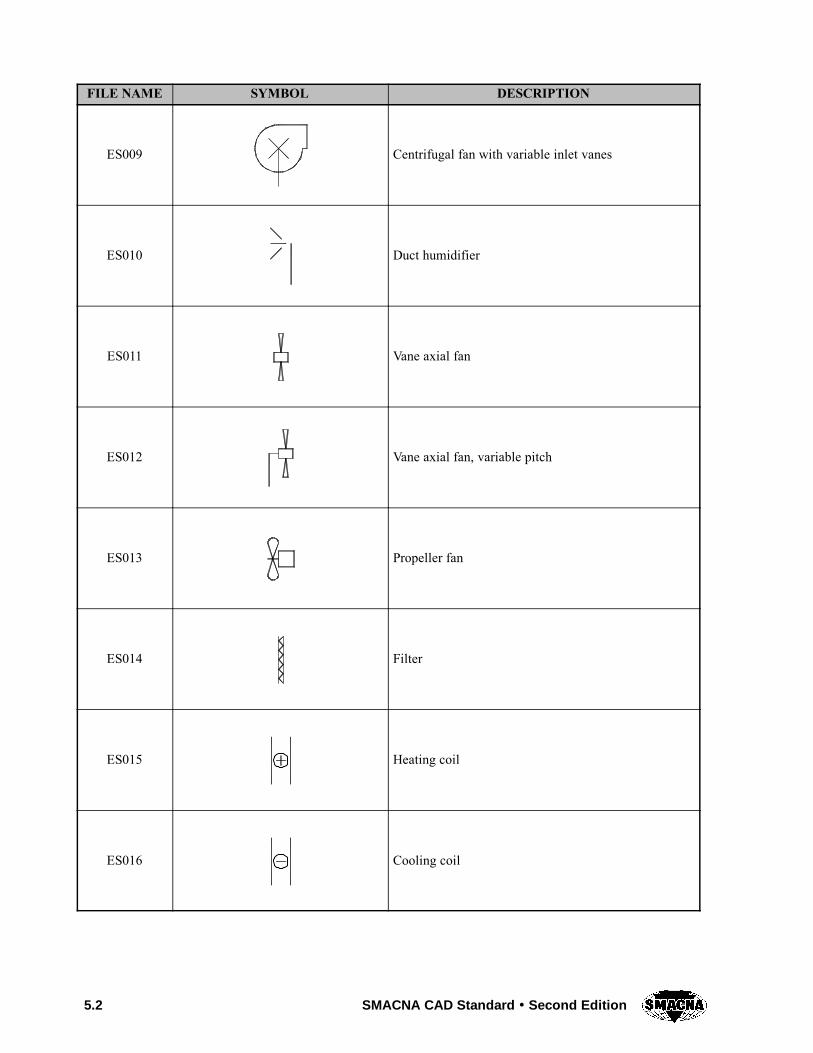
DESCRIPTIONSYMBOLFILE NAME
ES009 Centrifugal fan with variable inlet vanes
ES010 Duct humidifier
ES011 Vane axial fan
ES012 Vane axial fan, variable pitch
ES013 Propeller fan
ES014 Filter
ES015 Heating coil
ES016 Cooling coil

5.3SMACNA CAD Standard Second Edition
DESCRIPTIONSYMBOLFILE NAME
ES017 Electric duct heating coil
ES018 Air flow element
ES019 Air flow station
ES020 Parallel blade damper
ES021 Opposed blade damper

5.4 SMACNA CAD Standard Second Edition
THIS PAGE INTENTIONALLY LEFT BLANK

CHAPTER 6
CENTRIFUGAL FANSYMBOLS

CENTRIFUGAL FAN SYMBOLSCHAPTER 6
6.1SMACNA CAD Standard Second Edition
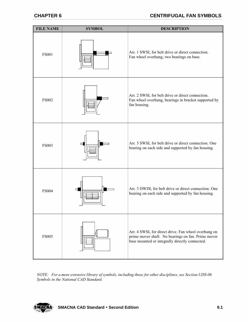
FILE NAME SYMBOL DESCRIPTION
FS001 Arr. 1 SWSI, for belt drive or direct connection.Fan wheel overhung, two bearings on base.
FS002Arr. 2 SWSI, for belt drive or direct connection.Fan wheel overhung, bearings in bracket supported byfan housing.
FS003 Arr. 3 SWSI, for belt drive or direct connection. Onebearing on each side and supported by fan housing.
FS004 Arr. 3 DWDI, for belt drive or direct connection. Onebearing on each side and supported by fan housing.
FS005Arr. 4 SWSI, for direct drive. Fan wheel overhung onprime mover shaft. No bearings on fan. Prime moverbase mounted or integrally directly connected.
NOTE: For a more extensive library of symbols, including those for other disciplines, see Section UDS-06Symbols in the National CAD Standard.

6.2 SMACNA CAD Standard Second Edition
DESCRIPTIONSYMBOLFILE NAME
FS006 Arr. 7 SWSI, for belt drive or direct connection.Arrangement 3 plus base for prime mover.
FS007 Arr. 7 DWDI, for belt drive or direct connection.Arrangement 3 plus base for prime mover.
FS008 Arr. 8 SWSI, for belt drive or direct connection.Arrangement 1 plus extended base for prime mover.
FS009 Arr. 9 SWSI, for belt drive fan wheel overhung. Twobearings with prime mover outside base.
FS010 Arr. 10 SWSI, for belt drive fan wheel overhung. Twobearings with prime mover inside base.
6.3SMACNA CAD Standard Second Edition
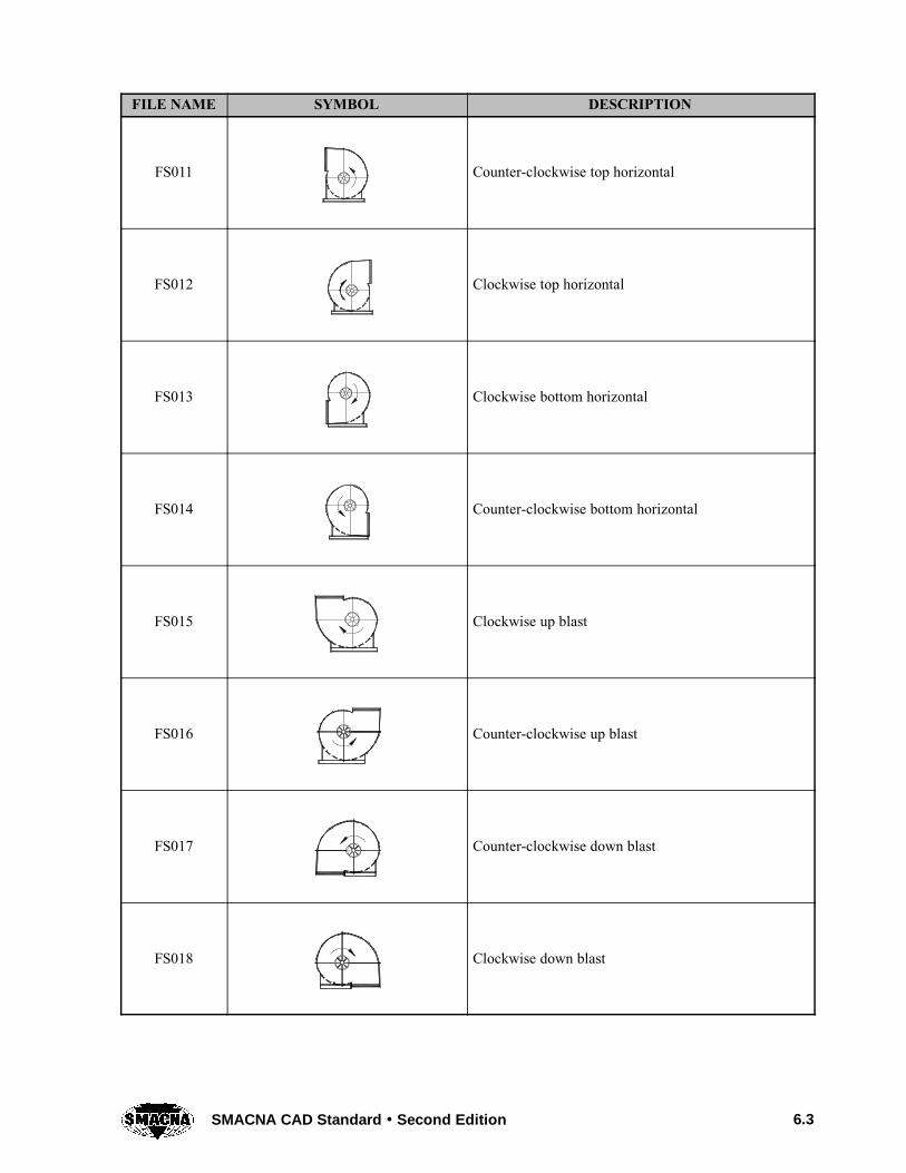
FILE NAME SYMBOL DESCRIPTION
FS011 Counter-clockwise top horizontal
FS012 Clockwise top horizontal
FS013 Clockwise bottom horizontal
FS014 Counter-clockwise bottom horizontal
FS015 Clockwise up blast
FS016 Counter-clockwise up blast
FS017 Counter-clockwise down blast
FS018 Clockwise down blast

6.4 SMACNA CAD Standard Second Edition
DESCRIPTIONSYMBOLFILE NAME
FS019 Counter-clockwise top angular down
FS020 Clockwise top angular down
FS021 Clockwise bottom angular up
FS022 Counter-clockwise bottom angular up
FS023 Counter-clockwise top angular up
FS024 Clockwise top angular up
FS025 Fan with top intake
FS026 Fan with horizontal right intake

6.5SMACNA CAD Standard Second Edition
DESCRIPTIONSYMBOLFILE NAME
FS027 Fan with right angular intake from above
FS028 Fan with right angular intake from below
FS029 Fan with bottom intake
FS030 Fan with horizontal left intake
FS031 Fan with left angular intake from above
FS032 Fan with left angular intake from below
FS033 Z Motor
FS034 Fan

6.6 SMACNA CAD Standard Second Edition
THIS PAGE INTENTIONALLY LEFT BLANK

CHAPTER 7
PIPING SYMBOLS

PIPING SYMBOLSCHAPTER 7
7.1SMACNA CAD Standard Second Edition
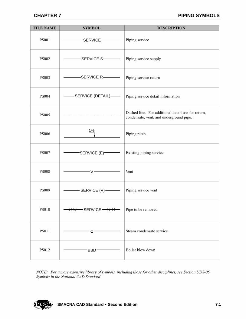
FILE NAME SYMBOL DESCRIPTION
PS001 SERVICE Piping service
PS002 SERVICE S Piping service supply
PS003 SERVICE R Piping service return
PS004 SERVICE (DETAIL) Piping service detail information
PS005 Dashed line. For additional detail use for return,condensate, vent, and underground pipe.
PS0061%
Piping pitch
PS007 SERVICE (E) Existing piping service
PS008 V Vent
PS009 SERVICE (V) Piping service vent
PS010 SERVICE Pipe to be removed
PS011 C Steam condensate service
PS012 BBD Boiler blow down
NOTE: For a more extensive library of symbols, including those for other disciplines, see Section UDS-06Symbols in the National CAD Standard.

7.2 SMACNA CAD Standard Second Edition
DESCRIPTIONSYMBOLFILE NAME
PS013 BFW Boiler feed water
PS014 PC Pumped condensate or vacuum pump discharge
PS015 VPD Vacuum pump discharge
PS016 FOS Fuel oil supply
PS017 FOD Fuel oil discharge
PS018 FOR Fuel oil return
PS019 FOV Fuel oil vent line
PS020 FOF Fuel oil fill
PS021 FOG Fuel oil gage line
PS022 HTWS Hot water for heating supply
PS023 HTWR Hot water for heating return
PS024 A Compressed air
PS025 LPS Low pressure steam
7.3SMACNA CAD Standard Second Edition
DESCRIPTIONSYMBOLFILE NAME
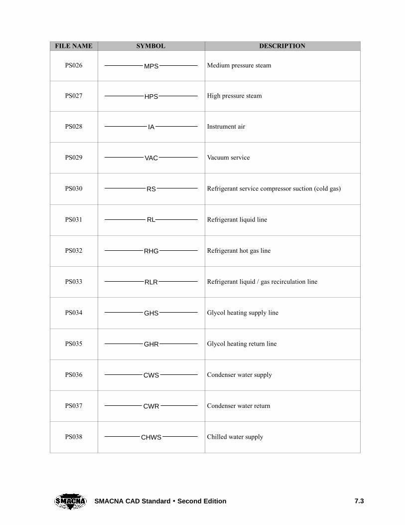
PS026 MPS Medium pressure steam
PS027 HPS High pressure steam
PS028 IA Instrument air
PS029 VAC Vacuum service
PS030 RS Refrigerant service compressor suction (cold gas)
PS031 RL Refrigerant liquid line
PS032 RHG Refrigerant hot gas line
PS033 RLR Refrigerant liquid / gas recirculation line
PS034 GHS Glycol heating supply line
PS035 GHR Glycol heating return line
PS036 CWS Condenser water supply
PS037 CWR Condenser water return
PS038 CHWS Chilled water supply

7.4 SMACNA CAD Standard Second Edition
DESCRIPTIONSYMBOLFILE NAME
PS039 CHWR Chilled water return
PS040 IW Indirect waste
PS041 CD Condensate drain line (HVAC)
PS042 HPWS Heat pump water supply
PS043 HPWR Heat pump water return
PS044 DTS Dual temp supply. Two pipe heating / cooling supply.
PS045 DTR Dual temp return. Two pipe heating / cooling return.
PS046 NPW Non-potable water
PS047 SS Sanitary soil piping
PS048 SD Above ground storm drain
PS049 ACID Acid waste piping
PS050 AV Acid vent piping
PS051 W Waste
7.5SMACNA CAD Standard Second Edition
DESCRIPTIONSYMBOLFILE NAME
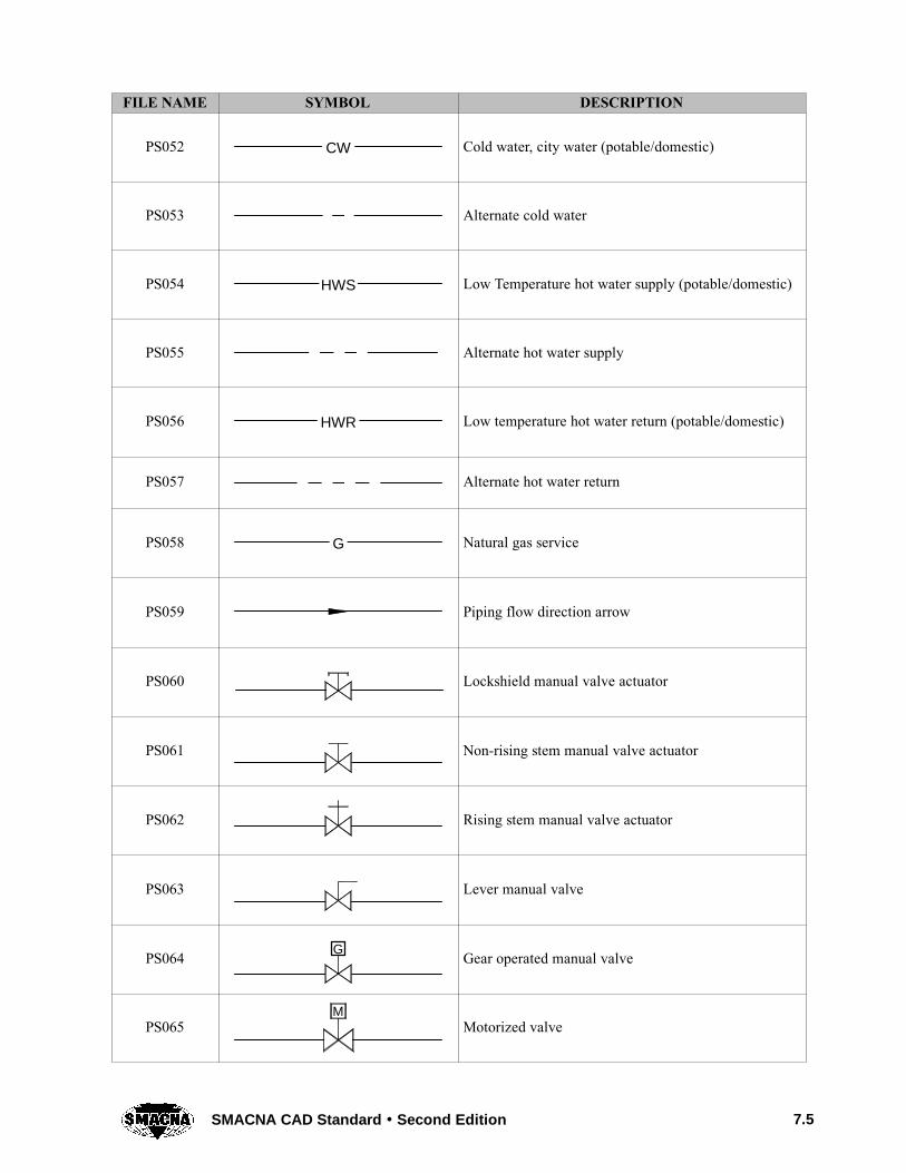
PS052 CW Cold water, city water (potable/domestic)
PS053 Alternate cold water
PS054 HWS Low Temperature hot water supply (potable/domestic)
PS055 Alternate hot water supply
PS056 HWR Low temperature hot water return (potable/domestic)
PS057 Alternate hot water return
PS058 G Natural gas service
PS059 Piping flow direction arrow
PS060 Lockshield manual valve actuator
PS061 Non-rising stem manual valve actuator
PS062 Rising stem manual valve actuator
PS063 Lever manual valve
PS064 G Gear operated manual valve
PS065M
Motorized valve

7.6 SMACNA CAD Standard Second Edition
DESCRIPTIONSYMBOLFILE NAME
PS066 Three-way valve
PS067 Ball valve
PS068 Closed ball valve
PS069 TEXT General symbol for special valve
PS070 Butterfly valve
PS071 Closed butterfly valve
PS072 Diaphragm valve
PS073 Closed diaphragm valve
PS074 Plug valve
PS075 Closed plug valve
PS076 Check valve
PS077 S Spring loaded check valve
PS078 Needle valve

7.7SMACNA CAD Standard Second Edition
DESCRIPTIONSYMBOLFILE NAME
PS079 Pressure regulator, pressure reducing from left to right
PS080 Pressure regulator, back pressure from left to right
PS081 Pressure regulator, differential pressure
PS082 Quick opening valve as used for blow down
PS083 Fusible link valve
PS084 Hose bib
PS085 Safety relief valve
PS086 Triple duty valve, combination shutoff, balancing andcheck valve
PS087 Triple duty valve, with measuring connections
PS088 Boiler stop and check valve
PS089 Refrigerant thermal expansion valve
PS090 Lateral
PS091 Tee

7.8 SMACNA CAD Standard Second Edition
DESCRIPTIONSYMBOLFILE NAME
PS092 Tee up
PS093 Tee down
PS094 Cross
PS095Elbow, drawn with radius. Either radius bend or 90degree line intersection is acceptable. Show reducingelbows by pipe dimension notation
PS096 90 degree elbow
PS097 45 degree elbow
PS098 Elbow facing up
PS99 Elbow facing down
PS100 Base supported below (elevation view)
PS0101 Pipe cap
PS102 Spring hanger
PS103 Thermometer well
PS104 Thermometer in a well

7.9SMACNA CAD Standard Second Edition
DESCRIPTIONSYMBOLFILE NAME
PS105 Temperature and pressure tap
PS106 Y-type strainer
PS107 Double basket strainer
PS108 PSD Pipe suction diffuser
PS109 Pipe guide
PS110 Pipe anchor
PS111 Piping ball joint
PS112 Piping expansion joint, expansion compensator
PS113 Piping flexible connection
PS114N
Orifice flange with descriptive tag number or textinformation “N”
PS115 Venturi flow measuring device
PS116 Pitot device
PS117 FD Floor drain

7.10 SMACNA CAD Standard Second Edition
DESCRIPTIONSYMBOLFILE NAME
PS118 Funnel drain
PS119 Shutoff cock
PS120 Pressure gage, with shutoff cock
PS121 Pressure gage with snubber and shutoff cock
PS122 Pressure gage with pigtail and shutoff cock
PS123 Automatic air vent
PS124 Automatic air vent with manual release, shutoff cock,and discharge piping
PS125 AS Air separator

CHAPTER 8
ENVIRONMENTAL CONTROLSYMBOLS


ENVIRONMENTAL CONTROL SYMBOLSCHAPTER 8
8.1SMACNA CAD Standard Second Edition
FILE NAME SYMBOL DESCRIPTION
CS001 MCC Motor control center
CS002 HC Humidity controller (pneumatic)
CS003 PC Pressure controller (pneumatic)
CS004 TC Temperature controller (pneumatic)
CS005 VSC Variable speed motor controller
CS006 BDD Back draft damper
CS007 EAD Exhaust air damper
CS008 FBD Face & by-pass damper
CS009 VXD Fan inlet vortex damper
CS010 OAD Outdoor air damper
CS011 RAD Return air damper
CS012 VD Volume damper (manual)
CS013 CS Current sensor
CS014 P Differential pressure sensor (binary)
CS015 PS Differential pressure sensor (analog)
NOTE: For a more extensive library of symbols, including those for other disciplines, see Section UDS-06Symbols in the National CAD Standard.
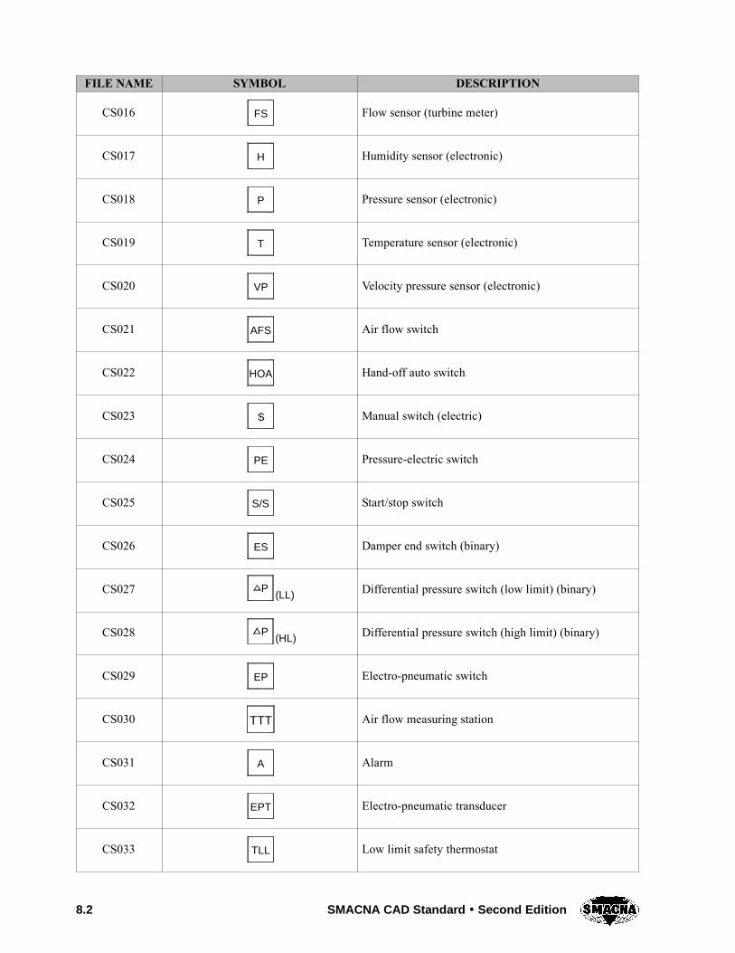
8.2 SMACNA CAD Standard Second Edition
DESCRIPTIONSYMBOLFILE NAME
CS016 FS Flow sensor (turbine meter)
CS017 H Humidity sensor (electronic)
CS018 P Pressure sensor (electronic)
CS019 T Temperature sensor (electronic)
CS020 VP Velocity pressure sensor (electronic)
CS021 AFS Air flow switch
CS022 HOA Hand-off auto switch
CS023 S Manual switch (electric)
CS024 PE Pressure-electric switch
CS025 S/S Start/stop switch
CS026 ES Damper end switch (binary)
CS027 P(LL) Differential pressure switch (low limit) (binary)
CS028 (HL)P Differential pressure switch (high limit) (binary)
CS029 EP Electro-pneumatic switch
CS030 TTT Air flow measuring station
CS031 A Alarm
CS032 EPT Electro-pneumatic transducer
CS033 TLL Low limit safety thermostat

8.3SMACNA CAD Standard Second Edition
DESCRIPTIONSYMBOLFILE NAME
CS034 MDM Modem
CS035 STR Motor starter
CS036 PR Pneumatic relay
CS037 SD Smoke detector
CS038 VXT Vortex shedding air flow transmitter
CS039 H Humidistat (space)
CS040 HC Holding coil
CS041 S Switch (pneumatic)
CS042 T Thermostat (space)
CS043 T Thermostat (space) night cycle
CS044 3-15 PSIG main air
CS045 20 20 PSIG main air
CS046 0-30 PSIG air gage
CS047 AO--X Analog output (DDC controller)
CS048 AI--X Analog input (DDC controller)
CS049 BO--X Binary output (DDC controller)
CS050 BI--X Binary input (DDC controller)
CS051 Manual reset

8.4 SMACNA CAD Standard Second Edition
DESCRIPTIONSYMBOLFILE NAME
CS052 High limit
CS053 Low limit
CS054 Controller
CS055 Wall mounted thermostat
CS056 Duct mounted averaging thermostat
CS057
T
Manually reset low limit thermostat
CS058 Pipe thermostat, well mounted
CS059 Surface and/or strap-on thermostat
CS060T
Manually reset high limit duct mountedfire protection thermostat
CS061N
Night thermostat
CS062 COGeneric controller, acronym denotescontrolled medium
CS063 Remote bulb thermostat
CS064 Remote bulb thermostat in well
CS065
WB
Wet bulb thermostat (use local language designator)

8.5SMACNA CAD Standard Second Edition
DESCRIPTIONSYMBOLFILE NAME
CS066
DP
Dewpoint thermostat (use local language designator)
CS067 Wall mounted humidity controller
CS068 Duct mounted humidity controller
CS069 Enthalpy controller
CS070 Pressure controller
CS071 Differential pressure controller
CS072 Combination temperature and humidity controller
CS073 Dual function and/or deadband temperature controller
CS074 UCM
Unit control module, more than a sensor or thermostat.May have an array of switches, indicators, andcommunication ports for controlling package units orterminal boxes. Subscript may denote variations.
CS075 Manual or setpoint adjustment “switch” (analog)
CS076 Minimum position switch
CS077 Two position switch, open-closed
CS0782
Single pole-double throw switch
CS0793
Three position switch
CS080 Single phase manual motor starter
CS081 Combination disconnect switch and magnetic motorstarter

8.6 SMACNA CAD Standard Second Edition
DESCRIPTIONSYMBOLFILE NAME
CS082 Magnetic motor starter
CS083 Disconnect switch
CS084 Fused disconnect switch
CS085 3 Three pole contactor
CS086HOA
Hand-off-auto switch
CS087 Momentary pushbutton
CS088 Maintained contact push button
CS089 Proportional manual controller
CS090 VSD Variable speed drive controller
CS091 Time clock
CS092 2 Dual channel time clock
CS093 CP Control panel
CS094 MCP Microprocessor control panel
CS095 Smoke detector
CS096 Duct mounted smoke detector
CS097 Relay, subscript denotes action
CS098 NOR NO (single pole, Normally Open)
CS099 RNC
NC (single pole, Normally Closed)

8.7SMACNA CAD Standard Second Edition
DESCRIPTIONSYMBOLFILE NAME
CS100 RDT DT (single pole, Double Throw)
CS101 DPNOR DPNO (Double Pole, Normally Open)
CS102 DPDTR DPDT (Double Pole, Double Throw)
CS103 SCRSilicon Controlled Rectifier (SCR) electric heatcontroller
CS104 LEFT Flow switch
CS105 RIGHT Flow switch
CS106IT
Interval timer (override or temporary operation) switch
CS107 TD Time delay relay
CS10810 SEC (B)
TDTime delay relayExample:(B): delay on break0 to 60 second delay
CS1090--60 SEC (M)
TD
Time delay relayExample:(M): delay on make0 to 60 second delay
CS110 B RIM C
Controller, 3 to 5 portsB: Branch outputM: Main powerI: Primary InputR: Reset input (optional)C: Control point adjust (optional)
CS111 DAB CM I
P
Single input controller with control point adjust portD: Direct actingP: Proportional control
CS112 RAB RM I
PI
Dual (primary and reset) input controllerRA: Reverse actingPI: Proportional plus integral control
CS113 Sensor / transmitter / transducer / transformer
CS114 Wall mounted temperature sensor (“sensors” arebroad range devices with no setpoint)
CS115 Duct mounted temperature sensor point sensing
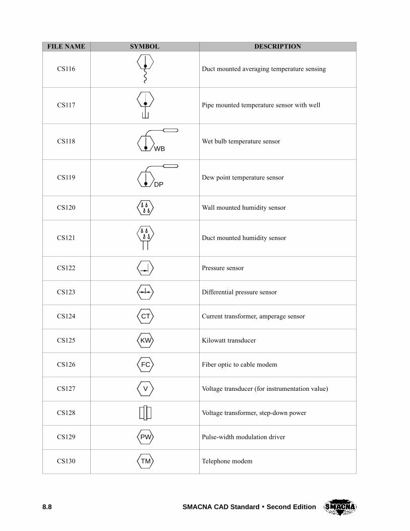
8.8 SMACNA CAD Standard Second Edition
DESCRIPTIONSYMBOLFILE NAME
CS116 Duct mounted averaging temperature sensing
CS117 Pipe mounted temperature sensor with well
CS118WB
Wet bulb temperature sensor
CS119DP
Dew point temperature sensor
CS120 Wall mounted humidity sensor
CS121 Duct mounted humidity sensor
CS122 Pressure sensor
CS123 Differential pressure sensor
CS124 CT Current transformer, amperage sensor
CS125 KW Kilowatt transducer
CS126 FC Fiber optic to cable modem
CS127 V Voltage transducer (for instrumentation value)
CS128 Voltage transformer, step-down power
CS129 PW Pulse-width modulation driver
CS130 TM Telephone modem

8.9SMACNA CAD Standard Second Edition
DESCRIPTIONSYMBOLFILE NAME
CS131 EPElectric-pneumatic relay (solenoid valve two-positiontype output)
CS132 ETElectric-pneumatic transducer (variable pneumaticoutput)
CS133 CO Carbon monoxide sensor
CS134 2CO Carbon dioxide sensor
CS135 R Refrigerant gas sensor
CS136 O2 Oxygen sensor
CS137Analog controlled digital output (ACDO) outputswitches between 0 and 1 as analog input variesbetween two bounds
CS138 Digital controlled analog output switches betweentwo analog signals as input switches between 1 and 2
CS139 Low signal detector
CS140 High signal detector
CS141 Signal reverserOutput is maximum level minus input.
CS142 A Average output is average of inputs
CS143 Sequencer, ratio relay, output goes 0 to maximumas input varies noted range
CS144 Ratio function, output varies between noted rangeas input varies between noted range.
CS145 IN
OUTD
PSP
IProportional-integral-derivative (PID) function, with“connections” for input, output, setpoint, and band/gain adjustments for P, I, and D

8.10 SMACNA CAD Standard Second Edition
DESCRIPTIONSYMBOLFILE NAME
CS146 Analog input function
CS147 Digital input function
CS148 Analog output function
CS149 Digital output function
CS150 Totalizer (pulse count) input
CS151
Software analog pointAn analog value created with a computer programwhich appears like a physical point to users othernames: pseudo point, virtual point
CS152 Software digital point
CS153
Software commandable analog pointA software value within a program which may bedisplayed with physical points and is easily changeableexample: setpoint
CS154
Software commandable digital pointA software status within a program which may bedisplayed with physical points and is easily changeableexample: motor on-off
CS155GI
Global received analog input. Value received fromanother location via the communication network
CS156GO
Global origin analog input. Value output to otherlocations via the communication network
CS157GI
Global received digital input. State received fromanother location via the communication network
CS158GO
Global origin digital input. State output to otherlocations via the communications network
CS159 Constant value written into a program (changed byrewriting the program)
CS160 Parameter value used within a program which maybe changed for program tuning

8.11SMACNA CAD Standard Second Edition
DESCRIPTIONSYMBOLFILE NAME
CS1610--60 SEC (M)
TDTime delay. Digital transition from 1 to 0 is delayeda specified time. Example: (M): delay on make 0–60second range
CS162 Time of day, value from real time clock
CS163 DT Date, value from real time clock
CS164 DA Day of week, value from real time clock
CS165 “And” output is true (1) if both inputs are true
CS166 “Or” output is true (1) if either input is true
CS167 “Exclusive Or” output is true (1) if either input istrue but not both
CS168 “Add” output is sum of inputs
CS1692
1“Subtract” output is input 1 minus input 2
CS170 X “Multiple” output is product of input 1 multipliedby input 2
CS1711
2“Divide” output is input 1 divided by input 2
CS1722
1 “Greater than” output is true (1) when input 1 isgreater than input 2
CS1732
1 “Less than” output is true (1) when input 1 is lessthan input 2
CS174 “Equal” output is true (1) when inputs are equal
CS175 Square root output is square root of input

8.12 SMACNA CAD Standard Second Edition
DESCRIPTIONSYMBOLFILE NAME
CS176 TS Time schedule
CS177 OS Optimum start program
CS178
RampExample: a ramp function where a step increase of asignal from 0 to 100 causes a smoothly ramped outputsignal of 0 to 100 over a 180 second duration. A rapiddrop in the input signal is not affected by the ramp (0ramping time)
CS179 Actuator, spring return
CS180 Actuator, spring return with positive positioner
CS181 Actuator, floating
CS182 Actuator, two position electric spring return
CS183 Analog pressure indicator
CS184 Analog pressure indicator scaled for temperatureindication
CS185 Air compressor
CS186 AD Air dryer
CS187 Moisture trap
CS188 Compressed air filter
CS189 Operator console (CRT, key board)
CS190 Printer

8.13SMACNA CAD Standard Second Edition
DESCRIPTIONSYMBOLFILE NAME
CS191 Computer (pc)
CS192 Telephone output
CS193 Lightning protector
CS194 R Repeater, communications
CS195 M Main air
CS196 EPEP air (main air switched by an electric pneumaticrelay)
CS197 DNDay-night air (air that varies between day and nightcycles)
CS198 SWSummer-winter air (air that varies between summerand winter cycles)
CS199 B Branch air
CS200 Pneumatic line restrictor
CS201 Pneumatic line
CS202 Line voltage
CS203 Low voltage, 48 volts and less
CS204 Number of slashes denotes number of conductorsexample: two low voltage conductors
CS205 D D Digital communication
CS206 Generic line

8.14 SMACNA CAD Standard Second Edition
DESCRIPTIONSYMBOLFILE NAME
CS207 F F Fiber optic line
CS208 Software, binary
CS209 Software, analog
CS210 Disconnect switch, three phase
CS211 Circuit interrupter
CS212 Circuit breaker
CS213 Normally open limit switch
CS214 Normally open, held closed limit switch
CS215 Normally closed limit switch
CS216 Normally closed, held open limit switch
CS217 Normally open flow switch
CS218 Normally closed flow switch

8.15SMACNA CAD Standard Second Edition
DESCRIPTIONSYMBOLFILE NAME
CS219 Normally open liquid level switch
CS220 Normally closed liquid level switch
CS221 Normally open pressure switch
CS222 Normally closed pressure switch
CS223 Normally open temperature switch
CS224 Normally closed temperature switch
CS225
1 2
2-position selector switch (show open and closed polesas required)
CS226
1 2 3
3-position selector switch (show open and closed polesas required)
CS227 Rotary selector switch, five positions shown
CS228 Rotary selector switch with bridging contacts
CS229 Normally open pushbutton
CS230 Normally closed pushbutton

8.16 SMACNA CAD Standard Second Edition
DESCRIPTIONSYMBOLFILE NAME
CS231 Maintained contact pushbutton
CS232 Double circuit button
CS233 Ground connection
CS234 Chassis or frame connection (not necessarilygrounded)
CS235 Plug and receptacle
CS236 Time delay relay contact after coil is energized(normally open)
CS237 Time delay relay contact after coil is energized(normally closed)
CS238 Time delay relay contact after coil is de-energized(normally open)
CS239 Time delay relay contact after coil is de-energized(normally closed)
CS240 Normally open relay or contactor contact
CS241 Normally closed relay, overload, or contactor contact
CS242 Coil for relay, starter, timer, or contactor
CS243 Solenoid coil
CS244 Thermal overload element
CS245 Control circuit transformer

8.17SMACNA CAD Standard Second Edition
DESCRIPTIONSYMBOLFILE NAME
CS246 Auto transformer
CS247 3 phase motor
CS248 Resistor, heater
CS249 Rheostat
CS250 Potentiometer
CS251 Capacitor
CS252 MeterExample: volt meter
CS253 Fuse
CS254 Pilot lightExample: red pilot light
CS255 Pilot light, push-to-test
CS256 Horn, siren
CS257 Buzzer
CS258 Bell
CS259 Thermocouple

8.18 SMACNA CAD Standard Second Edition
DESCRIPTIONSYMBOLFILE NAME
CS260SHIELD
CONDUCTOR
Shielded couple. Show all conductors inside cable
CS261 Rectifier diode
CS262 Full wave rectifier bridge
CS263 Asymmetrical photosensitive cells
CS264 Symmetrical photosensitive cells
CS265 AC neon light
CS266 DC neon light
CS267 AC neon light with internal resistor

CHAPTER 9
FIRE PROTECTION SYMBOLS

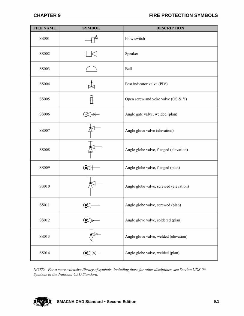
FIRE PROTECTION SYMBOLSCHAPTER 9
9.1SMACNA CAD Standard Second Edition
FILE NAME SYMBOL DESCRIPTION
SS001 Flow switch
SS002 Speaker
SS003 Bell
SS004 Post indicator valve (PIV)
SS005 Open screw and yoke valve (OS & Y)
SS006 Angle gate valve, welded (plan)
SS007 Angle glove valve (elevation)
SS008 Angle globe valve, flanged (elevation)
SS009 Angle globe valve, flanged (plan)
SS010 Angle globe valve, screwed (elevation)
SS011 Angle globe valve, screwed (plan)
SS012 Angle glove valve, soldered (plan)
SS013 Angle glove valve, welded (elevation)
SS014 Angle globe valve, welded (plan)
NOTE: For a more extensive library of symbols, including those for other disciplines, see Section UDS-06Symbols in the National CAD Standard.

9.2 SMACNA CAD Standard Second Edition
DESCRIPTIONSYMBOLFILE NAME
SS015 Angle hose valve (elevation)
SS016 Fire hydrant
SS017 Fire Department Connection
SS018 Butterfly valve
SS019 Check valve
SS020 A Up and down sprinkler at same location
SS021 Up sprinkler
SS022 Pendant sprinkler
SS023 Upright sprinkler or rise (sprig)
SS024 Pendant sprinkler on drop
SS025 Sidewall sprinkler
SS026 Piping (lines) ½ width of main
SS027 Piping (mains) two times width of lines
SS028 System riser
SS029 Hose valve (angle valve)
SS030 PA Preaction valve
SS031 Deluge valve

9.3SMACNA CAD Standard Second Edition
DESCRIPTIONSYMBOLFILE NAME
SS032 Rise up on piping
SS033 Drop in piping
SS034 Tamper switch for valves

9.4 SMACNA CAD Standard Second Edition
THIS PAGE INTENTIONALLY LEFT BLANK

APPENDIX A
CAD PROJECTPROTOCOL


CAD PROJECT PROTOCOLAPPENDIX A
A.1SMACNA CAD Standard Second Edition
A.1 INTRODUCTION
The audience for this document is the SMACNA member who has been successfully using a CAD system in-houseto prepare his own design and fabrication drawings. The member is now facing the next step with his CAD system.
You may ask yourself—Why should I go any further with CAD? After all, my company is using CAD effectively tomake the drawings we need to make and now we’re making them much more productively than we did on the boards(or maybe we aren’t, which raises other questions). We went through a long, expensive learning curve to get this farwith our basic CAD system. Why should we do any more? Why not just continue to exploit our current productivitygains and settle for that?
Today’sCADsystems can be used for farmore than just drawing lines onto your computer screen. If you are only usingyour system for electronic drafting, you are missing out on the greater part of CAD’s potential to make your life easier.You are missing opportunities that some of your competitors are already exploiting.
What can someone who is already using CAD successfully gain by going further? Among other possibilities, you can:
S use CAD with application software to automate complex and repetitive design calculations
S pass the design drawings you make with your CAD system into a CAM system that will be a real part of yourfabrication process
S qualify for projects that require sheet metal and air conditioning contractors to:
S receive and use CAD files during the design process
S deliver CAD files to the general contractor or project owner at the end of the project.
S receive CAD files from other members of the project team and use them to save yourself work
S use CAD to offer additional services or useful data to the general contractor or project owner
In addition to changes that are taking place within the operation of an individual contractor or within the team for asingle project, industry-wide initiatives are underway which will influence the way automated systems are used inprojects.
The Industry Alliance for Interoperability is pursuing its goal of enabling interoperability in the AEC industry. A cur-rent project will define how electronic models of project work will be developed within computer systems and thenhow the this model will be used and shared among the members of a project team. The goal of the project is that theelectronic model and the information it contains will be easily accessible to every member of the project team andthat every member will be able to add his own work input to the model in a way that the rest of the team can easilyread. The IFC (Industry Foundation Classes) Specification that describes how this process might work is under devel-opment right now.
The Industry Alliance for Interoperability’s Project Model Specification is only one of the initiatives currently beingconsidered or developed. Other professional organization are developing their own approaches. Initiatives are beingdeveloped in other industries.
Your computer system is going to let you work in greater harmony with the other members of your project teams. Youwill be able to work quicker, more efficiently, more accurately, and with fewer wasted motions.
You can realize benefits by using your CAD system more creatively, more aggressively. At the same time, extendingCAD beyond the your own company presents some additional considerations, some additional challenges.
This document will:
S describe ways you can extend CAD use to boost productivity and qualify for more projects

A.2 SMACNA CAD Standard Second Edition
S describe the new issues you must consider when extending CAD use
S offer suggestions for a CAD standard that will help you take on more challenging CAD projects
A.1.1 Engineering/Owner Needs
The use of CAD in the sheet metal contracting sector of the construction industry has a long history. For example, sheetmetal firms have been using computerized manufacturing systems to custom-fabricate duct systems for years. Sheetmetal firmshave needed to coordinate their workwith other contractors formany years, since ductwork is traditionallythe largest system. Naturally, that need transfers developing and exchanging electronic drawings.
Specialty contractors, especially mechanical, sheet metal, electrical, and fire protection firms play the most importantrole for facility managers because it is the HVAC, plumbing, electrical, and fire protection systems which control thecomfort and life safety of the building.
Energy efficiency, indoor air quality, and occupant comfort and productivity are all by-products of the systemsinstalled by HVAC, electrical, and fire protection contractors.
It is the services of the specialty contractorswhouse the latest technology in data and systemdevelopment and installa-tions that fulfill the long term operating needs of the building owner.
A.1.2 The Beginner’s CAD Standard
Beginning CAD users tend to use their CAD systems primarily to meet their own internal needs. If the CAD files theycreate are sufficient to get the job done internally, then that’s all they need and they are happy. Since the average begin-ner’s CAD use is purely in-house, his CAD staff can develop an in-house CAD standard that meets their own needsand they need not be concerned about how their standard fits with anyone else.
An in-house CAD Standard should include:
S procedures for planning, budgeting, and organizing project CAD work
S working procedures
staffing and scheduling
order of work
quality control.
S standards for layering CAD work
S standards for naming layers and other entities
S libraries of symbols, details, sheet borders, etc.
S custom menus and other modifications to the user interface to make an out-of-the-box CAD system specifi-cally fit the user’s projects and methods
S LISP routines and similar pieces of small-scale programming to make it easier to produce the work
S procedures for documenting ongoing and completed work
S procedures for archiving completed work
CautionIf your company does not have standards for its CAD work, your CAD work willprobably be inconsistent, hard to re-construct in case of a question, and difficultfor anyone but the original creator to decipher.
Consistently followed written standards are the minimum requirement.
A.3SMACNA CAD Standard Second Edition
Management should approve and actively support these standards. Compile them in written form. Make sure all mem-bers of the CAD staff understand and abide by them.
The specific details of your CAD Standard become much more important when you start to use your CAD systemsin more sophisticated ways and when you have to coordinate your CADwork with othermembers of the project team.
A.1.3 Standards for Use With Other Software
As you start to use your CAD systems for more than simple graphics, you often want to coordinate your CAD workwith other software. This might include libraries of parts, equipment, and details available from professional associa-tions like SMACNA, from vendors, or from project standards. It might also include design application programs thatwill work directly with the CAD system or exchange project data with the CAD system (extracting CAD data fromproject files, making calculations, preparing analyses, and perhaps even inserting data back into the CAD files).
Examples of this application software include programs for:
S performing energy analysis of a design
S calculating heating and cooling loads
S calculating duct pressure and air-flow through a system
S calculating duct sizes
S producing bills of materials
S estimating quantities and costs
S value engineering
S estimating or monitoring service and maintenance requirements and activities
S coordination with automated fabrication equipment (CAM programs)
When using such design software, you must typically prepare your CAD work so it will coordinate with the designsoftware. For example:
S you may have to organize CAD work in a prescribed file structure for the design software to work properly
S you may have to draw graphic elements in specific layers or levels
S you may have to draw elements in a specific sequence or use specific commands to draw them
S you may have to use specific symbols drawn from libraries provided by the design software publisher (or,the design software may automatically place the symbols on your drawing)
S design software often requires you to work through the software in a specific order
Using design software often requires you to revise the CADStandard that served youwell when youwere only produc-ing simple graphics in-house. Your updated CAD Standard must recognize the requirements of your new design soft-ware and produce data in formats that the design software can use.
A.1.4 Standards that include Project Requirements
You will eventually encounter opportunities to work on projects in which the other project team members expect toexchange CAD files during the project, and you will be required to deliver CAD files to them or receive files fromthem at one or more points during the work.

A.4 SMACNA CAD Standard Second Edition
In such cases, you may not be able to use your in-house CAD Standard or you may have to modify it to meet projectrequirements.
When becoming involvedwith such projects, you typically learn that the project has its ownCADSpecificationwhichyou must follow while doing the project work. The CAD Specification is not the whole CAD Standard. It addressesthe structure of the work to be done and the procedures for exchanging files between project teammembers, but it doesnot govern internal procedural issues (though its requirements may be such that you will have to modify your internalprocedures to meet it).
Still, the Project CAD Standard is very important and can greatly influence how you will perform project CADwork.Since it affects how and when you will perform the project CADwork as well as the content of the CAD files you willreceive and later deliver, the Project CAD Standard can significantly affect how much time and money it will cost todo the project CAD work.
CautionIf you are required to follow a Project CAD Specification that is different from theone you usually use, this can significantly affect what it will cost you (in time andmoney) to perform project CAD work.
The Project CAD Specification can have many origins.
Designer. The Project CADSpecification may start with the original CAD drawings prepared by the project designer.You may just be required to follow the CAD spec the project architect or engineer adopted at the beginning of theproject for his own reasons. This CAD spec may not fit your needs at all—it may even make it harder for you to doyour own work.
SSSS Contractor/Construction Manager. The Project CAD Specification may come from the project’s general con-tractor or constructionmanager. It may have been developed to address the needs of the general, the constructionman-ager, and the subcontractorswhowill be exchangingCAD files during the project. In such a situation, the project CADspec may be a closer fit to your own in-house CAD Standard.
SSSS Owner/End User. The Project CADSpecification may have been developed to assure that the finished CAD fileswill work with a specific planned post-design or post-construction use for the CAD files. The project owner or generalcontractor may require that your CAD files fit into a particular project CAD specification to produce CAD files for-matted to:
S develop an overall project quantity take-off and cost estimate
S fit into an automated project management program that will let the general contractor or constructionmanag-er plan, schedule, monitor, and coordinate the project work
S populate the databases required for a facility management system
S establish an automated maintenance or material handling system
Wherever the Project CAD Specification originates, you must take time before you sign any agreements to study andevaluate the CAD spec. You must understand how the CAD spec will affect your work, your costs, and your schedulebefore you agree on a price for the work.
A.2 REQUIREMENTS
Suppose you have been using CAD successfully in-house to produce your project drawings. What can you expect toencounter when you start working on projects that require you to exchange files with other project team members?
A.2.1 Project CAD Specification
Early on in such a project, you will be faced with a Project CADSpecification. This document describes how the proj-ect CAD work is to be done. Among other things, a Project CAD Specification should include descriptions of:

A.5SMACNA CAD Standard Second Edition
S System Elements
S Hardware definition
S Operating system—name and version number
S CAD software system definition—name and version number
S Other required application software
S Delivery medium
S Design Elements
S Directory and file structure
S Drawing names and descriptions
S Reference file structure
S Saved views/windows
S Layering/leveling conventions
S Entity naming conventions
S Line types, weights, and colors
S Pen tables
S Text fonts and sizes
S Symbols and other library materials
S Drafting Standards
S Procedures
S Number of and schedule for submittals
S Contents required for each submittal
S Procedure for each submittal
S Procedures for submittal review an acceptance
CautionCan you meet the requirements of the Project CAD Specification? Don’t make as-sumptions. Don’t take anyone’s word for it. Verify that you can meet the spec. Runtests. Do it before you sign an agreement.
If you can’t meet CAD specification requirements, figure out what it will cost youto acquire the required capability—all costs: hardware, software, installation,training, learning curve, etc.
You will have to deal with a CAD specification for every CAD-based project you work on. Setting up to follow a re-quired project CAD spec means that you must modify the CADStandard you developed when your company was just

A.6 SMACNA CAD Standard Second Edition
using CAD in-house. The Project CAD Spec may be similar enough to your own CAD Standard that you will onlyhave to make minor changes. However, the Project CAD Specification may be so different from your Internal CADStandard that you will have to make radical changes.
In either case, setting up to follow a Project CADSpecification will cost more than it did to just followyour ownCADStandard back when you didn’t have to exchange CAD data with anyone else. The cost may be relatively minor, orit may be significant. Either way, you must evaluate the project CADSpecification and estimate howmuch extra timeand money it will cost you to follow it. You must know your likely costs when you prepare your cost proposal.
If you work on a lot of your projects with the same team and encounter a consistent CAD specification for most ofthese projects, your CAD costs should be relatively similar from project to project and it should be relatively easy foryou to estimate these costs. If youwork onmany different project teams and face a different CADspec on almost everyproject, your CAD costs will be significantly higher and estimating these costs will require additional effort.
Are you involved in a CADproject that does not have a Project CADSpecification?Don’t let that fool you. Eventuallysomeone will decide that the required project CAD files will be useless unless they are prepared to meet standard. Inmany such cases a Project CAD Specification is imposed after the work is underway. Everyone is then expected tomodify their completed work to fit the newly-announced CAD spec. That’s an additional cost, and probably a delay,as well.
CautionNo announced Project CAD Specification? You’re not off the hook!
Eventually somebody will decide what theywant and tell youwhat CADspecifica-tion you have to meet. Your best bet is to determine the CAD spec requirement be-fore work starts.
Let’s look at some of the big issues included in CAD specs and see how they can affect your CAD system and yourwork.
A.2.2 Hardware
The Project CAD Specification seldom requires that the CAD user use specific hardware. Instead, the goal of thepeople establishing the CAD spec is to assure that every member of the project team will be able to read the electronicfiles it receives and will be able to submit electronic files that the other team members can read—and to assure thatwhoever establishes the requirement gets files in a format he can use.
There are currently three main types of computer hardware being used to run CAD software:
A.2.2.1 Workstations
These are systems fromvendors that include Bentley, Compaq, Hewlett Packard, SiliconGraphics, SunMicrosystems,and others.Most of these systems are quite powerful and designed to deliver high performance on demanding graphicsapplications (such as digital terrainmodeling or 3D rendering).Most of these systems operate proprietary RISC-basedprocessors and work on different versions of the UNIX operating system.
A.2.2.2 PC--compatible systems
IBM made its Personal Computer (PC) system in the early-1980’s and this system was soon accepted as an industry-wide standard. Since the PC system became the standard, many other vendors have developed computers that operateon the original IBM standard. This family of computers is called “PC-compatible.” These computers were originallydeveloped for non-graphic applications, but they have since evolved to the point where some PC’S are powerful ma-chines that can handle any graphic task. Most PC-compatible systems run under versions of Microsoft Windows.
A.2.2.3 Apple Macintosh systems
Apple has producedMacintosh systems since themid-1980’s and these systems have always been popular for use withgraphic applications. Macintoshes run under the Macintosh operating system.

A.7SMACNA CAD Standard Second Edition
The majority of today’s CAD stations are PC-compatible computers, but they are not necessarily better than worksta-tions or Macintoshes. For the purposes of this booklet, the most important differences between these systems are:
A.2.2.4 File compatibility
Many CAD and application programs offer versions that will run on more than one hardware system. Files generatedbyprogramversions thatwere designed for different hardware platformsmaynot be fully compatiblewith one another.For example, a CAD user whose CAD program runs on a PC CAD station may not be able to read a file generatedby the Macintosh-based version of the same CAD program unless a conversion or translation process is performed.
A.2.2.5 Software availability
Not all programs offer versions to run on all common hardware platforms. Furthermore, programs with versions foreach hardware platform may not have all versions of the program upgraded to the same revision level. For example,a user who has a different hardware platform than that described in the Project CAD Specification may have the re-quired CAD software, but may not be able to find a required application program written for his hardware or may findthat the version of the program that will run on his hardware is not the most current revision of the program (and maybe missing required features, line styles, fonts, or other recent updates).
If you do not have the same hardware that is described in the Project CAD Specification, you may still be able to pro-duce the required CAD work, but you must verify a few things before the project starts:
S Can you read the files you will receive from the general contractor or other project team members?
S Can the general read the files that your system produces?
S Can you acquire the necessary revisions of all the software required by the CAD spec?
Determine the answers to these questions before you determine a price or agree to do the work. Run some tests. Passsome sample files back and forth and see if they work. It’s much easier to invest some time in testing before the workbegins than it is towait until the day before you are supposed to deliver a big submittal and thendiscover that somethingdoesn’t work.
A.2.3 Software
A Project CAD Specification may require you to receive CAD files or deliver them in the format of a specific CADprogram. If you are to work as a member of the project team and communicate effectively with the other teammem-bers, this requirement is important. In essence, this requirement establishes the language that will be spoken by theteam during the project. If you meet the requirement, make sure you have both the specific CAD program requiredand required revision of that program.
The issue of revision number is important because different revisions of a program may not necessarily communicateeasily with one another. For example, AutoCADRelease 14 and AutoCAD2000 write design files in slightly differentformats. AutoCAD2000 can read files produced byRelease 14, howeverRelease 14 cannot readportions ofAutoCAD2000 files that contain object types that are not supported by Release 14.
In addition to specific CAD software, a CAD specification may require application software for use with the CADsoftware. These applications may include working environment software such as Autodesk’s Architectural Desktopor software that performs specific design calculations like the products developed by QuickPen.
You may be able to substitute for a required software application, but don’t assume anything. If you plan to use any-thing other than the program and version number that appear in the CAD spec, run enough tests before work starts toassure yourself (and convince your client) that your alternative will work and produce results that the rest of the projectteam will accept.
A.2.3.1 Alternative or Compatible Programs
Encountering a CADspecification that calls for different tools than you already have, youmay fall for the “compatibleprogram” fallacy. You may be tempted by the vendor’s assurances that your program and the required program are

A.8 SMACNA CAD Standard Second Edition
“compatible,” that you can use your old tools and methods to produce the CAD files and then “translate” them tomeetthe CAD spec’s requirements.
CautionExercise cautionwhenever you hear the word COMPATIBLE applied to computerhardware or software.
Very few products are really fully compatible. Don’t assume anything. Don’t takeanyone’s word for it. Test all claims of compatibility.
Some CAD programs can accept files produced by other CAD programs—either directly, or through an intermediatefile format like .DXF. Data files can be passed back and forth between CAD programs and one program can actuallydisplay another program’s files. However, this “compatibility” of file formats constitutes a “translation” only if yourexpectations are modest.
Suppose a project CAD specification requires that data files be prepared with a CAD system you don’t have. If youplan to use your currentCADsystem toproduce your projectCADwork, to followyour current internal CADStandard,and then “translate” the files into the format of the required system in order to satisfy the required CADspec, youmaybe in for trouble. You will probably have to spend a lot of time massaging your CAD files to get them to fit into therequired file format and meet the requirements of the project CAD spec after the fact.
If you must do the work with your current CAD system and deliver files in the format of the required CAD system,you must plan your work carefully and plan it for the eventual translation. You must plan which line-styles in yourCAD drawings will correspond to which of the required line-styles in the files you will deliver. You must do the samekind of planning for colors, line-weights, layers/levels, fonts, symbols, etc. Each line you draw with your own CADsystem must be drawn to fit into your plan for the eventual translation.
Once you complete the CAD work with your own CAD system and then translate the files into the required format,you must check your new files to be sure that everything translated as you planned and that they satisfy the projectCAD spec. You must do this before you transfer electronic files to anyone else. This final step is just an elementaryquality control measure. Chances are that you will have to do some clean-up work after the translation. You may beable to hire someone else do your checking and make your corrections or you may have to get a copy of the requiredCAD program yourself, just so you can perform the quality control checking.
This may sound like a lot of work—it is! In order to use your own CAD system and submit required project files inthe format of a different CAD system, and follow the Project CAD Specification, you must:
S Plan your work to minimize translation problems
S Do your CAD work following the revised project CAD spec designed in the previous step
S Make the file translations
S Check the translated files and correct any errors that occurred during translation
You will have to perform the last two steps both for your final submittal and for every intermediate submittal duringthe project. This means significant time, effort, and expense.
CautionTranslating complex files between CAD systems is difficult—no matter what any-one may tell you. Avoid translations whenever you can. On a big project it maybe worthwhile to buy and learn the required CAD system instead of trying to dothe work with your current system and translate files.
A good working definition of “compatible” software systems is “different.” Translating complex CAD files to meeta specific CAD specification requires much more work than the vendors want you to think. Wherever possible, usethe required CAD program to do your work.
A.9SMACNA CAD Standard Second Edition
A.2.4 Networking
Networking is typically done within a company and it does not often touch on a company’s relationships with otherproject team networks. Networking offers many ways to improve productivity and team coordination as CAD userscan:
S easily pass electronic files back and forth—no more sneaker-netting
S access consistent centralized libraries of symbols and details
S share a single file among multiple users at the same time
S let users view files from other team members as reference files and coordinate work between teams
S let users share peripherals such as printers, plotters, mass storage, CD drives, etc.
In-house networking also poses some challenges:
S large storage devices require large, complex data structures that need careful planning
S administering and managing files on shared data storage devices requires ongoing effort
S access of individual users to specific files or groups of files must be controlled
S protocols must be developed for sharing files among project team members—checking files in and out andsharing changes on an equitable basis
Technology and management tools exist to address these challenges and they are all solvable.
If, however, youmust participate in some kind of team-wide network the scope and scale of these challenges increasesand several other problems arise.
Wide Area Networks (WAN’s) that can link several project teammembers in different locations pose solvable techno-logical challenges, but these are beyond the scope of this booklet. The most important concern about working on aWAN is that if you and other project team members share a network that contains everyone’s CAD files, you mustbe very careful about when and how the files are exchanged among the team members.
Some enthusiasts paint a rosy picture of a project environment in which everyone has constant unlimited access toeveryone else’s work all through the life of the project. This can be confusing and dangerous.
Putting it simply:
S Youdon’twant to use another teammember’s CADfiles until he is ready for you to use them (when his qualitycontrol procedures are complete and the files are ready for release). Otherwise, youmayaccess an incompletefile or one that contains a design option that is still not final.
S At the same time, you don’t want anyone using your CAD files until you feel they are ready.
CautionDon’t exchange CAD files with other project teammembers until everyone agreesthat the files are ready to share.
Agree in advance how any shared files can be used (and how they should notbe used).
This simple precaution will prevent misunderstandings and wasted efforts.

A.10 SMACNA CAD Standard Second Edition
In the days of manual drafting, teammembers were protected by the fact that they exchanged hard copies of drawingsand that were accompanied by transmittal letters and other documentation. When project team members work on ashared network, they need tools to prevent access to their drawing files until they are ready for others to use them andother tools to help them determine when and how the files will be exchanged.
A.2.4.1 Security
CAD file security is a serious issue—whether you are working on an in-house network or on some larger project-widenetwork. The critical issues involve protecting files from unauthorized access by either your own staff, othermembersof the project team, or outsiders who may intrude into a network.
Tools to address these problems are available, but they do not fall within the scope of this booklet. The important thingis to be aware that security questions are real issues that must be addressed.
A.2.4.2 Access
It is important to determine who should have access to which files in your CAD system, what kind of access they haveto which files, and when during the life of the project they have this access. Some people are quite concerned abouthackers and other parties gaining malicious access to their files. Certainly this is a legitimate concern.
Just as important, though, are concerns about non-malicious access to your files. These are concerns about people whoare legitimate members of your project team whomay gain access to portions of the project files that don’t fall withintheir responsibility, or just getting access to files before or after their part of the work is executed.
For example:
S Youmay not want some of your CAD users to have any access at all to certain files. Information in these filesmay be confidential or the person may just have no business looking at certain files.
S You may want to make files available for some team members to see at any time during the project, but youmay only want them to be able to edit the files during a specific phase in the course of the project.
More frequently, though, you will want to give most of your users enough privilege to call up project files and view,examine, copy, or plot them—but not enough privilege to modify them (this is often called read-only access). In addi-tion, you will want to grant specific people access privilege that will let them edit the drawing files for which theyare responsible (read/write access).
Many project teammembers will have read-only access to most of a project’s files and read/write access to only someof the files. For example, in a multi-disciplinary design firm a mechanical engineer may have read-only access to allproject drawing files and have read/write access only to the mechanical drawing sheets.
You will probably want to give the team read-only access to the reference files that describe existing conditions.
Network administrators generally have software tools at the operating system level that let them manage permissionsand levels of file access for the various members of the project team. These tools don’t operate themselves, though.The greater challenge is for the project management team to plan the project work and develop an overall scheme forallowing access to the files—and then to convey and explain this to the project team members.
One relatively painless way to control file access is with viewing software. Viewing utilities let users view and plotproject drawing files. Users can even add comments and marks to a drawing in the form of electronic red-lining orpost-it notes. These marks are stored separately and do not modify the drawing file at all.
Many viewing programs include document management features. Some let you assign several fields of non-graphicdescriptive information to the drawing files—drawing namesand numbers, drawing descriptions, release status, dates,names, etc.—and thenuse this data to organize, sort, and find project files. Some let you track revisions to your drawingfiles—logging every time someone accesses each file, logging that person’s identity, giving the user a place to entera verbal description of all work done during the work session.

A.11SMACNA CAD Standard Second Edition
Asan addedbonus, viewing software is generally easier to use thanCADsoftware andviewing software lets you accessproject files without having to own an expensive CAD software license. This is a cost-effective way to give a checkeror supervisor access to project drawing files that he will not be changing.
A.2.4.3 Revision Control
The content of project drawing files changes from day to day as CAD users work on them.
It is easy to make a copy of a drawing file at any time. There are many good reasons for making copies, e.g. you maydecide make a copy of a file to test an alternate design without modifying the original design, or you maymake a copyon which a specialty consultant will do his design work. As a result, copies of files proliferate.
Often a CAD project manager discovers that the network directories contain several different copies of a drawing file(and who knows how many copies have been written onto disks and carried away for use elsewhere?). Every copy isa little different from every other one.
CautionTake pains to keep track of which version of your electronic files are “current.”Keep track of which copies are “current” and also track which copies are madefor other purposes—record copies, archives, design alternative testing, referencefiles, etc.
This bookkeeping requires significant effort, but it is easier than much less stress-ful than re-creating a “current” file after you have lost track.
After considering the matter for a while, the project manager realizes that he doesn’t know which file represents the“real” and current design. He may even find that no single file contains all of the real or current design. Instead, eachof several drawings files on the network contains a portion of the real design, but not all of it. He faces a real challengegathering up all the portions of the real design that have been developed separately and combining them into a singledrawing file where all the changes fit together.
A smart project manager only has to experience this confusion once or twice before he realizes that revision controlis an important issue. It is critical to track each drawing file through its life and the life of the project. The person whomanages the project CAD work must:
S track which version of a file reflects the current design
S track file copies that are made to test alternatives or for other purposes and make certain that they do not getconfused with the current drawing
S when an alternative from a file copy is adopted into the project design, hemust manage its incorporation backinto the “real” project files
S purge or archive invalid or outdated copies of files
S keep track of drawing files that are distributed outside of his network, trying to determinewho has up-to-datecopies of the files
Thismay seem like a daunting task, but it is do-able. This is an administrative andmanagement challenge.Most impor-tant in implementing such a program are consistent visible support from company management and cooperation ofthe company’s CAD users.
A.2.4.4 Record Drawings
Project drawing files evolve and change through the whole life of the project. At different points during the project,project team members make interim submittals of their drawings. These submittals typically include copies of their

A.12 SMACNA CAD Standard Second Edition
drawing files as they stand at the time of the submittal. Once the submittal is made, project work continues and theactive working drawing files continues to change.
CautionKeep archived record copies of everything you receive from other project teammembers and of everything you send to them. Document these exchanges.
This is a basic project management/quality control measure. It is important in ahand-drawn project and it at least as important when you use a CAD system.
It is important to make copies of your drawing files as they were at the time of the interim and final submittals andsave them as project archives. Note that the “final” submittal seldom marks the end of the project, so you must alsokeep a copy of the final submittal in case later CAD work is done to change the current files.
These archives become your record copies of just what you submittedwith each interim file exchange. This precautioncan protect you if a problem should arise and there are questions about who had what information and when they re-ceived it. You will be able to consult your record copies and answer these questions.
CautionDon’t rely on electronic files as your long-term project archives. They won’t lastforever.
If you are going to maintain project archives of your solutions, you must plan your archives carefully. Although long-term electronic storage media is improving, your electronic files won’t last forever. Compact Disk (CD) technologyoffers the most hope for a cost-effective solution to archiving project files. Unrecorded CDs have a typical shelf lifeof 5 to 10 years. Once files have been written to a CDmanufacturer claims for integrity increase to maximums of 70to 200 years, provided that the CDs are stored in an environment that meets their specific requirements. TheAmericanNational Standards Institute has begun some work to substantiate such claims.
On the surface this is great news. Unfortunately, the more daunting problem is archiving the system required to readyour old drawing files. The rapid obsolescence of computer systems is the greatest obstacle to the long-term retrievalof your files. To be able to retrieve and edit your project files you should be ready to save the computer that createdthem, its operating system, your CAD software, and any utility software that you used to prepare the drawings.
CautionIf you do need to archive electronic files on a long-term basis, then be ready toarchive the computer system that you used to produce the files.
Even if you do go to this length to set up your electronic archives, your current best bet is that your paper copies ofyour drawings will still probably outlast your electronic drawings. Because of this, your archive must include hardcopies of all the drawings you plan to store as electronic files. Full-size reproductions, photo reductions, or microfilmare possible storage media. Thus, if you ever do need to retrieve a project file and it does turn out to be corrupted, youcan at least scan your paper drawing, perform a little optical character recognition on it, and not experience a totalelectronic loss.
If you are fortunate enough to successfully retrieve your electronic archive, your drawings can still be useless to youunless your archive includes:
S careful documentation of your electronic files that will let someone open the files years after the project iscomplete and find their way around the files (documentation should include descriptions of: the directoryand file structures, how the drawing files correspond to the plotted drawings, reference files, saved views,and anything else that might be useful)
S copies of transmittal documentation to indicate who received the files and when they received them
S a copy of the project CAD specifications

A.13SMACNA CAD Standard Second Edition
CautionConsider your own business, estimate your liability exposure, and decide howmuch archiving and documentation is necessary.
As aminimum, archive all official submittals. Archive other interim file exchangesas seems necessary. When in doubt, use caution.
A.3 EFFECTIVE CAD MANAGEMENT
CAD systems offer the greatest benefits when they are effectively managed (and they can punish weak management).GoodCADmanagement can pay for itself early in a company’sCAD involvement, even if the company just usesCADinternally and is not yet exchanging CAD files with other project team members. Even in these early stages of CADuse, good management can:
S help a company develop a CAD Standard that will let it do better CAD work
S help a company keep its CAD work well-organized and efficient
S motivate a company’s CAD users to work consistently
S let a company measure and monitor CAD productivity
S help the company achieve non-project goals like developing libraries and customization tools
A.3.1 CAD Project Standard
Develop and adopt a company-wide CAD Project Standard to assure consistent CAD work. Do it thoughtfully.
CautionDon’t start CAD work in your company without a company-wide CAD ProjectStandard. You need a standard to assure consistent, coordinated CAD work.
If you are doing CAD work without a company standard, make developing sucha standard your first priority.
When a company gets its first CAD system, it should adopt a CADStandard before its people start making CADdraw-ings. If a company just trains new CAD users and lets each of them invent their own standards, whatever they inventwill almost certainly be incompatible with anything anyone else in the company is using (and also incompatible withthe standards being used by clients and other project teammembers). By the time the company starts to work on CADprojects that involve multiple CAD users or exchanging CAD files with other project teammembers, each of its CADusers will be hip-deep in his own home-made system and will resent forcible attempts to change and follow someoneelse’s system.
When the companygets that first CAD system, it should study the standards that are beingused around it. The companyshould check:
S colleagues/competitors
S professional associations like the National Institute of Building Sciences and SMACNA (see Chapter 2)
S clients
S application software that includes a standard
These sources represent the environment in which the company will be doing its CADwork. What standards are theyusing?

A.14 SMACNA CAD Standard Second Edition
CautionAdopt a company CAD Standard that will let you work easily in your environment—astandard that will let you coordinatewith your clients andothermembersof yourproj-ect team.
A new CAD company should try to adopt a CAD Standard that is similar to those being used around it, particularlyif there is a dominant standard in its geographic region or area of specialization. Given enough time, a company’s ownCAD staff may invent the perfect CADStandard, one that fits its staff, its organization, its internal requirements betterthan anything else possibly could. This is no help, though, if the perfect standard is so idiosyncratic that it won’t letthe company communicate or exchange information with anyone else. (The company will also have to pay its stafffor the time it spends developing this perfect standard.)
In developing your CADStandard, make it your goal to design something that lets youwork effectively, not just inter-nally, but also with other members of the project team. If one standard is being used widely in your area by the peopleyou will be teaming with—just adopt it (maybe with a few necessary internal variations) and save yourself a lot ofeffort, both in development time and in later coordination.
A.3.2 Layering Guidelines
These are covered in the CADSpecification portion of the CADStandard. You can either develop your own CADspec(and its included layering guidelines) or receive it as part of a project inwhich you are about to participate.Most likely,you will do both in succession—develop your own standards and then have them temporarily (you hope) supplantedby the standards required for your projects.
CautionImplement general purpose or “standard” CAD Specifications thoughtfully.Don’t let the fact that they offer an option for every possible situation tempt youinto an overly-complex implementation.
Keep it simple. In implementing a general purpose CAD spec, use as few of its op-tions as each project will allow.
Take a close look at the CAD specs you receive as you plan how to apply them to specific projects. Most general pur-pose CAD specs are far too long and contain far too many choices to be used as-is on any one project. The CADLayerGuidelines, published and revised by the American Institute of Architects Press in 2001, will be longer than 40 pages.The National CAD Standard fills two thick volumes.
Neither of these guidelines necessarily contains more than they should—complex projects need complex data struc-tures, and the developers of these guidelines meant for them to apply to complex projects and cover a wide range ofsituations. Therefore, the guidelines do contain more choices than are required for any specific project.
If some aspect of your project is relatively simple and straightforward, keep the structure of the CAD data for thatproject segment as simple as you can. Let’s look at how this can work:
Example: SMACNA’s CAD Standard lists four layers for diffusers:
M-HVAC-CDFF HVAC ceiling diffusers
M-HVAC-ODFF HVAC other diffusers
M-HVAC-RDFF HVAC return air diffusers
M-HVAC-SDFF HVAC supply air diffusers
If your project is complex, you may need to use every one of these layers. If your project only contains a fewdiffusers,though, consider putting them all into a single layer, M-HVAC-CDFF. Remember: your goal is to keep your projectdata structure as simple as is appropriate for your project.

A.15SMACNA CAD Standard Second Edition
A.3.3 Text Style and Size
These are also covered by NCS in the Uniform Drawing Standard Drafting Conventions. One bit of advice about textstyles—use the fonts that come with your system wherever you can and avoid non-standard fonts. If you develop cus-tom fonts or buy fonts from a third party and then incorporate them into your drawings, you may have trouble passingyour data files to other teammembers. There are ways around these problems, but why complicate things unnecessari-ly?
CautionAvoid fancy or custom text fonts. Keep it simple—stick with the standard fonts thatcome with your CAD system and you will avoid unnecessary coordination prob-lems.
A.3.4 Library
Your company’s CAD Standard should include provisions for developing a library. One of the most important waysyou can improve your productivity with CAD is to let it help you avoid drawing things more than once. A library isthe most obvious way to do this.
CautionDevelop a CAD library. It will improve your productivity and make your workmore consistent.
Develop a basic library when you first get your system, then expand your librarywith every project.
Use your library.
Start your library with:
S Standard sheets with:
S borders and title blocks
S parameter settings for units, scales, text heights, etc.
S layering schemes
S Standard symbols
S Standard details
S Standard data structures for typical project types
S Custom software—LISP routines, macros, user commands, etc.—that will automate repetitive tasks
Develop a second tier of information that includes files archived from your previous projects from which materialmight be re-used. When closing out a project, comb the files for material that should be added to your library.
Before drawing anything new for the current project, consult your library for guidance or for material that can be re-used, either as it is stored or with minor changes.
Make library development an ongoing effort in your company.Material for your library can come frommany sources,including:
S specific library projects

A.16 SMACNA CAD Standard Second Edition
S harvesting efforts conducted at the end of a project
S material from your suppliers and manufacturers
S material distributed at the beginning of a project
To maximize your benefit from library use, you must make a specific effort to: a) keep the library growing and up-to-date, b) keep it well organized and well documented, and c) make sure your CAD users are familiar with and actuallyuse the library.
A.3.5 CAD and the Project Team
Different members of the project team will use their CAD systems and CAD drawing files in different ways and fordifferent purposes.
A.3.5.1 Designer/Engineer
The project designer or engineer uses CAD for several purposes:
S to develop his own design information
S to run calculations when they are required for the design
S to prepare project contract documents
S to fulfill special owner requirements
In a “standard” project, the designer/engineer does most of his CADwork during the initial project design process andhis CADwork ismostly complete before the contractors/subcontractors become involved in the project. Once he com-pletes his work, the designer/engineer has CAD files that may be made available for contractors/subcontractors to usewhile preparing their own work.
The paragraph above said that the CAD files from the project designer/engineer “may be made available.” This is nota sure thing and you cannot assume that it will happen.
Many designers/engineers are reluctant to pass their design files to a contractor/subcontractor. In the same way, youmay be reluctant to pass your own design files back to the general contractor or on to the project owner. The reasonfor this reluctance is often a concern about liability for the contents of the files. For amore detailed discussion of theseconcerns, see Liability on page A.23.
The picture changes in a design/build project. In such projects, the team is assembled earlier in the project. In manycases, the principal project teammembers have already been identified when the design work begins and the contrac-tors/subcontractors will work directly with the designer/engineer during design. The contractors/subcontractors maypropose design ideas, help evaluate design and system options, and provide cost estimates for multiple options beforefinal decisions are made.
Contractors/subcontractors may be asked to provide some project systems on a design/build basis, in which case theyact as their own consulting engineers. Design of the overall project design and sub-systems must be carefully coordi-nated in such situations (to keep an air distribution system clear of structural members or light fixtures, or example).
Contractors/subcontractors may exchange drawing files with the designer/engineer before the design is complete.When this happens, it is critical to document all exchanges, to insure that all parties understand just what informationis being exchanged and just what stage of completion the exchanged files represent.
When there are interim file exchanges, all partiesmust be particularly careful that everyone isworkingwith the currentversion of the files and that all team members are updated when previous “current” versions are superseded.

A.17SMACNA CAD Standard Second Edition
The good news to report is that read only drawing file formats are growing in popularity as well as the inexpensiveand frequently free file viewing software required to read them. Internet-based project collaboration service portalsnow offer unprecedented new opportunities to exchange information in a timely, responsible, and efficient manner.Test out these new technologies on smaller projects before committing them to larger projects where you have moreat risk. Ask the tough questions about Internet security to safeguard your intellectual property. Explore the full scopeof the cost of these services, so you do not experience any rude surprises as the size of your project document anddrawing database grows. Admittedly, it is always important to proceed with caution into new arenas, however it maybe equally important to avoid letting excessive caution prevent you from preceding to find out what these new technol-ogies can do for you.
A.3.5.2 Contractor/Subcontractor
The sheet metal and air conditioning contractor/subcontractor cannot usually start work before receiving basic designinformation from the designer/engineer. This information may include a preliminary specification for the facility orthe system the contractor/subcontractor is to provide. It may include a layout for the whole project that will show thecontractor/subcontractor just where his installation must fit.
In manual drafting days, the contractor/subcontractor received this information as written specs or blueprints. Nowthat we have CAD systems, you may be able to get this information in an electronic format that will let you draw yourown work right on top of the designer’s drawing file. This can save you significant time and effort. It can save youmoney and help you finish your drawings just that much sooner.
When you receive CAD files from other project team members, though, you must determine whether:
S the files reached you on schedule
S the files were prepared according to the Project CAD Specification
S the files contain the information you expected
S the files contain up-to-date information
S whoever provided the files warrants that the information contained in them is accurate
Once you receive information from the designer or the general and then do your own CAD work, you may have topass your CAD files on to other parties. You may have to transfer your files to the general who may plan to use themhimself in a project scheduling or project management system or may pass them on to the project owner. You mayhave to pass your files directly to the owner.
CautionUnderstand your contractual relationships within the project team. Who do youhave a contract with? Who has a contract with you? What do the contracts re-quire?
Consider these relationships when you receive a request to deliver electronic files
If you do have a contract with someone who makes such a request, determine howthe request fits into what the contract requires you to do.
If you do not have a contract with the requester, you may not be required to deliveranything.
If you are required to submit your CAD files at the end of yourwork, the filesmust be prepared according to the ProjectCAD Specification. If you pass your CAD files on to other project team members, be sure you completely documenteach submittal as described previously.

A.18 SMACNA CAD Standard Second Edition
Don’t send your CAD files to someone just because they asked for them. In doing so youmay be voluntarily assumingliability that is not included in your contract. Deliver your CAD files only when you are required to do so by a contrac-tual relationship or a legal requirement.
Understand your contractual relationships.Who is your contract with?What does your contract require you to deliver?
Suppose you are the air conditioning contractor and that your contract is with the general contractor.
What if the plumbing contractor asks for your CAD files? You do not have a contract with the plumbing contractor.You are not receiving any compensation for working with him. Anything you give him is a gift and by giving it youassume an undefined liability for the content of what you deliver. You are assuming liability that is not required byany written agreement and you are doing it for free! You have no contractual obligation to the plumbing contractorand you should not give him anything.
Suppose that in the situation above the general contractor asks you to deliver CAD files to a third party. You may notbe required to make the requested deliver, but you want to be a responsible teammember and keep the project movingforward. You will probably end up making the delivery as requested, but here are some suggestions:
S Determine whether your contract requires you to make the delivery.
S If the delivery is not required, consider requesting additional compensation. After all, you will be doingworkthat was not included in the original agreement.
S Deliver the requested material to the general contractor and let him pass it on to the third party. If you can’tdo this, deliver the material with a transmittal document which states that you are making the delivery at thegeneral contractor’s request.
S Document whatever you deliver. Pay special attention to describing what you deliver and its state of comple-tion at the time of the delivery. Do not assume responsibility for updating the recipient on changes that occurafter delivery.
A.3.5.3 Customer/Owner
The customer/owner may:
S provide CAD files to the project team at the beginning of the design process, or
S require that the project team deliver CAD files at the end of the project
At project start-up, the owner may provide files containing information about existing project conditions. This mightinclude: site survey data, drawings of existing building conditions in the project area or existing adjacent structures,or drawings from previous project phases (preliminary designs, for example).
CautionWill you be receiving electronic files from the project owner or other project teammember?
Don’t assume anything about how useful the files will be or how much time andmoney you will save by having these files.
Check these files carefully and determine how you will use them before you agreeto a price or schedule for your work.
Owners usually provide this information to prevent the project team from having to gather the information themselves.Owners often expect that their providing these files will save work for their project team and, thus, reduce design fees.Sometimes this works out. Often it does not.

A.19SMACNA CAD Standard Second Edition
When you receive such files, you must verify a couple of things.
First, what is the condition of the electronic files?
S Are they well organized and were they executed carefully?
S Are they compatible with your CAD system and easy to read?
S Do they contain information you can use?
S Do they contain a lot of other information from which you will have to extract the useful parts?
S Does the value of the information contained in the files exceed what it will cost you to use them?
Second, is the information contained in the files accurate?
S Can you rely on the information without having to go to the field and verify it?
S Is the party who prepared the files available to answer your questions about them?
S Does the ownerwarrant the accuracy of the information? Fewowners will make such assurances, but withoutsuch a warranty, you may have to field verify everything in the files. This makes the filesmuch less valuable.
An owner may require you to deliver files at the end of the project for several reasons:
Project Archive. The owner may want to keep CAD files as a project archive. An electronic archive is more volatilethan hemay understand. Electronic files can become inaccessible and unusable through deterioration of magnetic me-dia or through changes in hardware or software.
By the time the owner gets around to trying to use archived CAD files, he may find that he cannot read the files andmay then start looking for the “responsible” parties. Your best protection is to educate the owner before the projectstarts. If you do not have direct access to the owner, you can only work through channels to spread this information.
Use in Later Project Phases. The owner may want to use the CAD files from your phase of the project to help imple-ment later phases of the project (furniture and finishes or installation of equipment, for example).
A.3.6 Timing and Timing--Related Issues
CAD files may be exchanged many times during a project. With each exchange youmust be aware of what is happen-ing and you must ask yourself some questions.
Use in Facility Management. The owner may want to use the files to start a facility management system. In suchsituations, the owner may modify your files and go on to use them in ways you had never considered.
CautionYour CAD files can be changed without a trace by anyone who has copies of them.
Protect yourself from liability for the problemsof peoplewhomodify your files andthen use them inappropriately.
Include appropriate language in your agreements and in transmittals.
You must protect yourself from liability for problems arising from use of modified versions of your files. Make sureyour contract language provides such protection. Also, keep careful documentationof your submittals (both electronicfiles and hard copies) so that in case a problem should arise, you will be able to determined just what was includedin the files when you delivered them.

A.20 SMACNA CAD Standard Second Edition
A.3.6.1 Pre--Project
This occurs before any project work starts, or, if you are a sub-contractor, before your part of the project work begins.Pre-project CAD data exchanges typically consist of files you receive from the owner or the general contractor thatcontain (or are supposed to contain) information you will need to do your work.
In working with such data exchanges, you must determine:
S When will you receive the files? Exactly when are you supposed to receive the files? Who is responsible forproviding them (get the name of a specific person)? If the files are not delivered when scheduled, will youget more time (or money) to complete your work?
S Who made the files you will receive?Was it the owner, the designer, the general contractor or maybe athird party who is not on the project team? Is there anyone you can contact with your questions about the files or are you on your own when it comes to using them?
S What do the files contain?Do they contain the information you need? Do they contain a lot of other informa-tion that you can’t use? Howmuchworkwill it require to separate the useful material from the parts you can’tuse?
S How were the files made?What was the CAD specification? Was it followed carefully or will you haveto do a lot of editing to get the information you need organized so you can use it conveniently?
S What is the quality of the files? Are they complete? Are they correct? Will you have to field verify any ofthe information?
A.3.6.2 During the Project
While the project work is going on, there are typically two kinds of CAD file exchanges:
S passing files back and forth with other members of the project team for coordination purposes
S making required progress submittals to the project owner or the general contractor
In considering such exchanges, determine:
S Project CAD Specification.What is the CAD specification for the files to be exchanged? Do you plan to fol-low your own internal CAD Standard and later translate your CAD files to meet the CAD spec? Howmucheffort will it take for you to make this translation?
S Exchange Schedule. Howmany CAD files exchanges will you make? (Howmany are required in your con-tract?) When will you make the exchanges? (Remember that each exchange will take time and money.)
S Exchange Contents.What informationwill each exchange include?Which drawingswill be included?Whatwill be shown on each drawing? What stage of completion does each exchange represent? How can you usethe files you receive?
S Documentation. Howwill you document these exchanges to track: what youdeliver, what you receive,whenexchanges are made, etc.?
S VersionControl.Howwill you assure that other teammembers are using themost recent versionof yourwork—and how will they know if they don’t have the most current version? How will you know that you havethe most current version of files from other team members?
S Acceptance. This issue arises in the case of progress submittals when the project team submits preliminarydata to the project owner or perhaps constructionmanager. In these situations, the party receiving the submit-

A.21SMACNA CAD Standard Second Edition
tal is supposed to review it in a timely manner and notify the project team of any exceptions taken to the pre-liminary design. On receiving this notification, the project team members can make required changes andproceed with their work. How can you be sure review and acceptance will be timely? How can you protectyourself from being forced by deadline pressures to proceed with your work before receiving the necessaryapproval? See Liability on page A.23 for more discussion.
S Ownership.Whowill own the electronic files that you deliver to others? In the case of coordination files ex-changed with other project team members, this is not a significant issue. It is an issue when design files arepassed to the project owner or end user. See the discussion of this issue in the next section.
A.3.6.3 Post Project
These data exchanges are made when everyone’s work is complete and final project documents are prepared. Theseexchanges usually involve having project team members pass their files on to the general contractor and then to theproject owner for the owner’s ultimate use.
In making such exchanges, determine.
S Project CAD Specification. What is the CAD specification for the files you will submit?
S Submittal Contents.What specific information are you required to submit?
S Acceptance. At what point is the recipient deemed to have reviewed and accepted the files? When are yourelieved of responsibility for the content of the electronic files?After all, electronic files deteriorate over timeand they can be modified without a trace. At some point the recipient must assume responsibility for main-taining the files and safeguarding their contents. See Liability on page A.23 for further information.
S File Ownership. Who will own the electronic files you deliver to others? This becomes an important issuewith the files that the project owner or end-user receives. Ownership will determine which party can use theinformation contained in the files and how the files can be used. The electronic files of your CAD drawingsare a database that is potentially muchmore valuable to the owner or end-user than your paper drawings everwere, so don’t rush to give them away without compensation. Depending on the specifics of your contract,you can retain ownership of your files, transfer ownership to the owner or end-user, or establish a shared own-ership of the files.
Thismay be the time tomeet with the client or end-user to determine just howhe plans to use your files and thendiscusshow you might work with the files and provide additional services.
S TheReceiver.Whowill ultimately receive your submittal—the general contractor, the project owner, the enduser, or consultant for a later phase of the work? Howwill this party use your files? Is this an appropriate usefor your files? If not, how can you protect yourself?
S Archiving Issues.Does the project owner plan to keep your files as an archive?Does he understand the limita-tions of electronic archives? What should you keep for your own archive?
A.3.7 Data Exchange
Project have become increasingly sophisticated in recent years. Today’s project team includes many members, manymore thanwere involved just a fewyears ago. A typical project teammight include: designers and their design consul-tants, contractors and subcontractors, manufacturers and suppliers, and the project owner and end users.
Project team members work together in a complex matrix of relationships which changes as the project moves frompreliminary phases through the end of construction and user occupancy.
Project information flows through this matrix. At any time some project teammembers maywant project informationanother member has or is developing. At any time you may have information that another team member will want.

A.22 SMACNA CAD Standard Second Edition
Before automation, much project information was passed back and forth between project teammembers. Automationand CAD systems particularly have made it even easier to pass information back and forth among project teammem-bers and to do it quickly.
The free, rapid flow of information among project team members can help team members communicate quickly, andcan save time and effort as teammembers have the information they need instead of having to wait for it, and can keepthe project moving forward.
The uncontrolled flow of project information among project team members can also pose risks. Without proper con-trol, team members can end up:
S workingwith data that is incorrect, not ready, unchecked, or for other reasons should not have been exchanged
S working with data that represents a design alternative rather than the actual design
S working with design information that has not been approved for release
S working with outdated information
S working with multigenerational copies of data files
S not knowing whether changes were made to the files as these copies were madeInformal information ex-changes among project team members can lead to these problems and raise serious liability problems.
In a well-run project, data exchanges between the teammembers are established in the contracts and are thenmanagedcarefully. The manager may be the principal designer, the general contractor, the construction manager, or some otherparty. The data exchangemanager’s rolemay even pass from one party to another as the project moves from one phaseto the next.
Without effective management of data exchange within the project team, each team member is on his own. Carefulteam members will implement their own data exchange management systems and there will be a great deal of dupli-cated effort.
Whether project data exchanges are well managed or not, each project team member must protect himself. His goalsshould be:
S to use CAD files received from others only if he can verify that they contain correct and current information
S to assure that the information he is using from outside sources is kept current as changes occur
S to assure that he releases only correct and current data to other team members
S to document the whole process and develop a paper trail in case of later questions
These principles apply when you are working on a multi-member project team. They also apply when you are justworking with other teams or even just other individuals in your own company.
Whenworking on amulti-member project team, your first step is to determine the nature and structure of your contrac-tual relationships.
Don’t give your CAD files (or other project documents) to anyone with whom you do not have a contractual or a legalobligation (such as fire marshals and others with review authority). This caution applies to other project team mem-bers, of course, but it also applies particularly to outsiderswhowant the information for their own uses. Let the generalcontractor or the project owner handle these requests.
Don’t deliver CAD files unless the contract requires that you deliver them. If you are a sub-contractor to the generaland you need to exchange CAD files with another sub, make the exchange through the general.

A.23SMACNA CAD Standard Second Edition
CautionWhen you exchange electronic files documentation is critical.
Document everything that you receive and everything that you give to anyone else.
Documentation can help you re-construct events after the fact if questions arise.More immediately, though, documentation can help you and your project team tokeep track of where things stand on a day-to-day basis.
Let the general (or designated data exchange manager) manage these issues. Let the general keep track of who hasreceived what, when the delivery occurred, percentage completion at the time of the exchange, etc. Let the generalact as the data coordinator and traffic cop for the project.
Assume, then, that you have settled these contractual issues and are preparing to exchange CAD fileswith othermem-bers of the project team.
Before you pass CAD data files to another project team member:
S Determine what you are delivering. What files are included? Which drawings do they include? What werethe design assumptions under which the drawings were made? What is the currency date of the material youare delivering? How complete are the drawings at the time of the exchange.
S Be sure you deliver only what you intend to deliver. Check your files before you send them. Check all thelayers/levels and make certain they do not include material that you do not want to send—such as proprietarymaterial, private notes, etc. If you only want to deliver part of a file’s contents, write a new file that containsonly what you want to send. This simple precaution can save you embarrassment.
S Document your delivery carefully. Keep a copy of your transmittal and other documents describing exactlywhat is being delivered. Keep hard copies of the drawings included in the CAD files. Keep copies of the CADfiles. Keep a record of who is receiving the delivery and of your relationship with this party (establish whyyou are making the delivery). List any third parties who you know will be receiving copies or your delivery.
S Update recipients. Understand that you will want to keep the recipient updated on any changes (the projectdata coordinator may be responsible for seeing that this happens, but don’t just assume that it will occur).
Whenever you receive CAD data files from another project team member:
S Determine what you have received.What files are included? Which drawings do they include? What werethe design assumptions under which the drawings were made? How complete are the drawings at the timeof the exchange. Who made the files you have received—the sender, or another party? Much of this may beindicated on the sender’s transmittal, but you should verify it anyway.
S Document it carefully. Keep the sender’s transmittal and any related correspondence. Keep any notes thatyou make during your confirmation of the delivery. Keep a copy of the files as you received them in yourproject records.
S Commit to updating. Understand that you must keep yourself updated on any changes to the information.
A.4 LIABILITY
In discussing liability issues, a useful starting point is the assumption that each project teammember should be respon-sible for his own work. This principle would be very helpful if each team member could work independently, neverinteracting with other team members, and just submit his finished work at the end of the project.
Unfortunately, this is not the case, nor has it ever been the case except in the very smallest and least complex projects.
A typical project in today’s environment includes several participants who are separate entities and organizationswhich must work together as a team. The success of any one team member depends on the other team members doingtheir jobs correctly: before he begins work, while he is working, and after his work is finished.

A.24 SMACNA CAD Standard Second Edition
In this kind of team model, the team members must work cooperatively and interdependently throughout the life ofthe project. They must pass a great deal of information (CAD files and many other things) back and forth during theproject and they must be able to rely on the information they receive and stand behind the information they pass toothers.
This complicates the liability picture.
It is possible to develop aworkable liability structure from the complex matrix of relationships that constitutes today’stypical project. Steps toward such a liability structure include:
S project contracts that describe data exchanges between project members
S who will provide information and who will receive it?
S how many exchanges will be made?
S what will be included in each exchange?
S what is the state of data currency at each exchange?
S what is the furnisher’s responsibility for the data provided?
S how can the data be used once it is received?
S a structure to manage the day-to-day details of data exchange
S tracking scheduled data exchanges
S assuring that exchanges are made as scheduled
S receiving CAD files from the parties who are supposed to provide them
S verifying that the files contain the information they are supposed to contain
S conveying the files to the parties scheduled to receive them
S assuring that the parties who receive CAD files are kept current as changes are made to the files
Establishing and operating this kind of structure requires a significant effort and additional costs—initially. The effortpays off quickly in terms of improved data flow, reduced confusion, and clear liability.
If this structure is established on a project-wide basis and if teammembers feel confident it will work smoothly, a sav-ingswill be achieved by reducing duplicated efforts among teammembers as each tries to cover his own liability expo-sure.
The overall goals of such an organization must include:
S A successful project in which the work runs smoothly and without delays, everyone makes a fair profit, andat project’s end everyone involved (including the project owner) feels good about everyone else on the teamand looks forward to working with them again.
S A free and open exchange of information among the project team members. Such an exchange means thateach party receives from other project team members the information he needs to perform his own work. Italso means that each party must provide information about his own work to other parties need for their work.
S An equitable and appropriate distribution of liability among the members of the project team.

A.25SMACNA CAD Standard Second Edition
A.5 CONCLUSION, SUMMARY, AND RECOMMENDATIONS
CAD systems offer many potential benefits to SMACNA members.
The most obvious benefits are using CAD in-house to produce your own drawings. Select a good CAD system andadopt an in-house project CAD standard similar to those used by your colleagues and you can experience significantgains in productivity as you produce your drawings, perform design calculations, generate quantity take-offs, etc.
You can benefit further fromCADusewhen you receive CAD files from other project teammembers. Using this infor-mation, you can:
S get drawings of existing site conditions in CAD format (rather than having to gather the information and drawit up yourself)
S learn about the design intentions of other team members
S perform ongoing coordination between your work and that of other team members
In achieving this second tier of benefits, though, you will encounter challenges in the areas of data coordination, addi-tional costs, and liability.
These challenges are best addressed by project-wide efforts that beginwith the general contractor or the project owner.Lacking such efforts, you must take whatever steps you can to protect yourself (and so must all the other team mem-bers).
The considerations above relate primarily to automating projects as they are currently performed.
Creatively used, your CAD system can become a tool that will be useful in other ways, too.
CADwork can be away for you tomake yourself known to the project owner. Using modern technological tools effec-tively to produce successful work can let you stand out on the project team and keep you from getting lost among allthe other sub-contractors.
Your CAD system can be a great sales tool. CAD includes tools that will let you present your work to your clients informs they can readily understand. A 3Dmodel or a process flow simulation can help your client understand your de-sign with much greater clarity than you could achieve with 2D mechanical design drawings, performance charts, orverbal descriptions. Your sales efforts will be muchmore effective when you can communicate your proposal clearly,when you can really show it to your client.
Your CAD system will let you offer new products and services that extend beyond the construction of the project. Asyou use your CAD system to develop your project design, you build an electronic database that describes the facilityand your design. If developed carefully, this database is a product that has great potential value to your client.
You can add non-graphic data (attaching to the graphic representation of a piece of equipment information such as:manufacturer name, model number, serial number, installation date, maintenance recommendations, etc.) and offeryour client a set of electronic files that will connect directly into his facility management system. Such a system canhelp a client manage system maintenance activities, assure inventory of belts and filters, or even issue preventivemaintenanceworkorders. You can evenuse the database yourself and offer tomonitor andmaintain the client’s facilityyourself.
All in all, CAD can be a valuable tool for the SMACNAmember. Like any other new and powerful tool, though, youmust use it with planning and care.

A.26 SMACNA CAD Standard Second Edition
THIS PAGE INTENTIONALLY LEFT BLANK

APPENDIX B
CAD PROJECT SPECIFICATIONCHECK LIST


CAD PROJECT SPECIFICATION -- CHECK LISTAPPENDIX B
B.1SMACNA CAD Standard Second Edition
System Elements
SSSS Hardware Definition
S Does the Project CADSpecification require that you use a specific computer hardware platform? For exam-ple, IBM PC-compatible.
S Does your computer hardware meet the requirement?
S Is your computer hardware compatible with the requirement?
SSSS Operating System
S Does the Project CAD Specification specify the name and version number of the native operating system ofthe files you will receive? For example,Microsoft Windows 2000.
S Does it specify the name and version number of the operating system under which the files you deliver willbe read?
S Can your system work with this requirement?
SSSS CAD software
S Does the CAD specification specify the name and version number of required CAD software? For example,AutoCAD 2000.
S Do you have the required CAD software?
S If not, will your CADsoftware let youdeliver files that are compatible with the required format? (Think aboutthis carefully. Make tests to verify this compatibility before you sign an agreement.)
SSSS Other software
S Does the CAD specification require you to use any other software such as design calculation software?
S Can you meet this requirement?
SSSS Delivery Medium
S Does the CAD specification require you to receive or deliver electronic files on a specific medium. Forexample, 3½" floppy disks, Iomega ZIP disk, electronic mail, or an Internet project collaboration portal.
S Can you meet this requirement?
Design Elements. Does the Project CAD Specification establish standards and requirements for:
S Directory and file structure. How must your data directories and files be organized?
S Drawing names anddescriptions.What drawings are you required to produce?Whatmust theybe named?Whatinformation must they include?
SSSS Reference file structure. What reference files must be attached to design files, and howmust they be organized?
SSSS Saved views/windows. Are there requirements for saved views that will include only portions of drawing files?(These might specify several saved views of a drawing which each have different layers turned on or off. They mightalso specify views that include specific portions of a larger drawing.)

B.2 SMACNA CAD Standard Second Edition
SSSS Layering/leveling conventions. How must the drawing information be divided into layers? What informationgoes into which layer? What is the name/number of each layer?
SSSS Entity naming conventions. What names must you use for: assemblies, blocks, cells, details, symbols, etc.?
SSSS Line types, weights, and colors. What line types, weights, and colors must you use? In what circumstances areyou required to use them?
SSSS Text fonts and sizes. What line text fonts and sizes must you use? In what circumstances are you required to usethem?
SSSS Symbols and other library materials. What library materials must you use? How are you required to use them?
SSSS Drafting Standards. What are drafting standards for the project?
Procedures. What are the established procedures for handling the project CAD work?
SSSS Number of and schedule for submittals. Howmany electronic file submittals are you required to make? Whenmust you make them?
SSSS Require submittal contents. What must be included in each submittal?
SSSS Procedure for each submittal. How must each submittal be made? Do procedures vary between submittals?
SSSS Review and acceptance procedures. How will your submittals be reviewed and accepted? (Will they be re-viewed and approved in a timely manner? or will you have to proceed with the remaining work without approval?)

APPENDIX C
THE CAD PROJECTCHECK LIST

THE CAD PROJECT -- CHECK LISTAPPENDIX C
C.1SMACNA CAD Standard Second Edition
This checklist does not contain all the answers. This would be impossible. Instead, the list aims to offer some specificguidelines, and also describe the questions you should ask through the life of a project.
Once you consider these questions and determine the answers, you can make decisions about the project. You can de-cide:
S whether you want to pursue the project at all
S whether the project material includes all the information you need
S whether you should request more information
S whether you should ask for more time or money to meet some project requirements
PRE--PROJECT
S The Contract
S Who will your contract be with? the project owner? a general contractor? a constructionmanager? someone else?
S Have you worked with this party before?
S If so, was the previous project successful?
S If not, can you learn anything about the party?
S Have other team members been identified? Who are they?
S The CAD Requirement
S Why is CAD use required?
S Where does the CAD Requirement come from? the project owner? the contractor orconstruction manager? the project end-user?
S Who will receive the CAD files? Will all deliveries go to the same party, or will they be split?
S How will these parties use the CAD files?
S Are these appropriate uses for the files? Can the files really be used in the way the recipientplans?
S Is the party that requires the files CAD-knowledgeable? or will you have to spend time edu-cating him?
S Hardware and software requirements
S Can you meet the requirements with your current system?
S Will you have to buy anything else?
S Will you have to go through a learning curve with the new items?
S What will it cost to implement these changes?
C.2 SMACNA CAD Standard Second Edition
S The Project CAD Specification
S Is there a Project CAD Specification, or will you have to work with the owner, contractor, etc. todevelop one? (and what will this effort cost?)
S How different is the Project CAD Specification from the CAD spec you normally use in yourpractice?
S Will you be required to translate CAD files to meet the spec?
S Will you be able to test the file exchanges before you must make a submittal?
S What will this effort cost and how long will it take?
S The Project CAD Standard
S What parts of your work are you required to prepare with CAD?
S What CAD materials will you receive from other project team members?
S How will the material reach you? and who will be responsible if you don’t receive it as prom-ised?
S Who produced the material? and is anyone available to answer your questions about the ma-terial?
S Material content: does it contain the information you want?is it all there? is other informa-tion mixed in with the information you need? will it be hard to separate out the informationyou need?
S Material organization: to what CAD specification was the material prepared? was it followedclosely?
S Material quality: does anyone certify that the material contains correct information?will youhave to field verify any of the information? what will the field work cost?
S Can you test samples of this material before you sign a contract?
S What will it cost you to use this material?Will using it really save you anything or will it justcomplicate things?
S What CAD data must you submit?
S What are the required submittals and when must they be made?
S What must be included in each submittal: which drawings? what information must be in-cluded on each drawing? what is the required degree of completion? -- answer these ques-tions for each submittal.
S Is it likely you will have to make unscheduled submittals?
S What will it cost you to make the submittals (beyond the cost of just doing the CAD work)?
S Will the general contractor or some other party adequately manage the CAD data during theproject as it passes among project team members? or will you have to spend time managingthis yourself?

C.3SMACNA CAD Standard Second Edition
DURING THE PROJECT
S File Exchanges
S What electronic files will you receive during the execution of the project?
S What electronic files are you required to deliver during the execution of the project?
S Documentation
S Document all the CAD files that you receive from others in the project team.
S Document all the files you deliver to other team members and third parties.
S Documentation must include:
S the date of the exchange
S the party received from (or delivered to)
S the reason for the exchange
S identification of the files exchanged
S identification of the drawings included
S identification of the contents of each drawing
S identification of the state of completion of each drawing at the time of the exchange.
S electronic files and hard copies of the drawings
S Liability. Limit your liability for the electronic files you pass to others by:
S establishing how your files are intended to be used
S using hold-harmless language to protect yourself from liability for use of your files for unintendedpurposes or for use of files that have been modified
S clearly establishing in your documentation which of the files you pass to others are finished andwhich are preliminary, incomplete, or unfinished
S Currency
S Verify that the electronic files you receive are current as of the time you receive them or as of somedate/time indicated in the documentation.
S Indicate a currency date/time in the transmittal documentation that accompanies any files you pass toothers.
S Update
S Before completing your work, verify that any information you have received from other parties hasbeen updated and is current.

C.4 SMACNA CAD Standard Second Edition
S As you complete your own work, try to assure that the parties who received your electronic files ininterim submittals have received updates and are using current information.
POST--PROJECT
S Submittals
S What electronic files and which drawings are you required to submit at the end of the project?
S Design drawings?
S Construction drawings?
S Record drawings? If yes, does your fee include updating the drawings during construction?
S Drawings especially designed to fit into a facility management program or other end-usersystem?
S What is the required format for these files? Is it the same as that for the interim submittals?
S What is the procedure for the owner accepting your electronic files?
S Who will own your electronic files after you submit them?
S What archiving activity will you have to perform at the end of the project?
S What archives does the contract require you to maintain? (avoid such requirements if you can)
S What archives will you want to maintain for your own uses?

APPENDIX D
TRANSMITTAL LETTER


TRANSMITTAL LETTERAPPENDIX D
D.1SMACNA CAD Standard Second Edition
The following is a sample letter of transmittal to accompany CAD file deliveries. This transmittal letter is intendedto:
S establish disclaimers limiting the compatibility of the files to a specific hardware and software system
S establish an acceptance period for the recipient to review and accept the electronic files (and then acceptresponsibility for maintaining them)
S hold the writer harmless from liability for misuse of the files or use of file copies that have been modified
S establish precedence of the sealed hard copy of each drawing over the corresponding electronic file
The letter requests that the recipient endorse a copy of the letter and prints of the drawings and return these to thewriter.
This letter is probably not appropriate for use with file exchanges among design team members for coordination pur-poses, but it or something like it should be used at the end of the project when final sets of files are delivered to theowner or end user.
The sample transmittal letter printed here is intended for use in situations where the party receiving the files will alsoreceive ownership of the files and the drawings. The letter should be somewhat different if the designer/contractor isto retain drawing and file ownership or if ownership is to be shared.
Dear CLIENT NAME:
The enclosedDESCRIBEMEDIA contains the CAD files created for PROJECTNAME. These files are being de-livered to you per our agreement dated DATE. The files contain DESCRIBE FILE CONTENTS. Also enclosedare two complete sets of blue-line copies of the plotted CAD files.
The submitted data files are intended towork only as described in the agreement. These files are compatible onlywithDESCRIBECADSYSTEM (example: AutoCAD 2000, operating on an IBM-compatible PC usingWindows 2000).FIRMNAMEmakes no representation as to the compatibility of these files beyond the specified release of the above-stated software. CLIENT NAME agrees to save and hold FIRM NAME harmless for uses of the file data outsideof or beyond the scope of this agreement.
Because data stored on electronic media can deteriorate undetected or be modified without FIRM NAME’s knowl-edge, CLIENT NAME agrees that it will accept responsibility for the completeness, correctness, or readability ofthe electronic media after an acceptance period of 30 days after delivery of the electronic files, and that upon the expi-ration of this acceptance period, CLIENT NAME will indemnify and save harmless the FIRM NAME for any andall claims, losses, costs, damages, awards or judgments arising from use of the electronic media files or output gener-ated from them. FIRM NAME agrees that it is responsible for the accuracy of the sealed drawings that accompanythe submittal, and that such accuracy is defined as the care and skill ordinarily used by members of the consultant’sprofession practicing under similar conditions at the same time and in the same locality.
The electronic files are submitted toCLIENT NAME for a 30-day acceptance period. During this period, CLIENTNAME may review and examine these files and any errors detected during this time will be corrected by the FIRMNAME as part of the basic agreement. Any changes requested after the acceptance periodwill be considered addition-al services to be performed on a time andmaterials basis, at FIRMNAME’s standard cost plus terms and conditions.
The CLIENT NAME shall be permitted to retain copies of the drawings and specifications prepared in CAD formatfor the CLIENT NAME’s information in their use of the project. Due to the potential that the information set forthon the computer disks and/or magnetic tapes can be modified by the owner, unintentionally or otherwise, the FIRMNAME reserves the right to remove all indicia of its ownership and/or involvement from each electronic display.
Any use or reuse of altered files by CLIENT NAME or others, without written verification or CAD adaptations byFIRMNAME for the specific purpose intended, will be atCLIENT NAME’s risk and full legal responsibility. Fur-thermore, CLIENT NAME will, to the fullest extent permitted by law, indemnify and hold FIRM NAME harmless

D.2 SMACNA CAD Standard Second Edition
from any and all claims, suits, liability, demands, judgments, or costs arising out of or resulting from any use of thesefiles.
CLIENT NAME is hereby requested to review the contents of the CAD files and compare the contents of the CADfiles to the two sets of copies of the plotted CAD files. If the CAD files are in agreement with the copies of the plottedCAD files submitted, please so acknowledge this by signing this letter below and both sets of the copies of the plottedCAD files, and return this letter and one set of copies of the plotted CAD files to FIRM NAME within the 30-dayacceptance period indicated above. If the CAD files do not agree with the copies of the plotted CAD files, please in-form FIRM NAME as soon as possible.
Failure to sign and return this letter and one set of contract drawings within the 30-day acceptance period, FIRMNAMEwill assume thatCLIENTNAMEwill have accepted theCAD files as beingwithin conformance of the agree-ment between CLIENT NAME and FIRM NAME.
FIRMNAMEwill not make any attempt, nor willCLIENTNAME hold FIRMNAME responsible, to maintain thecompleteness, correctness, or readability of CAD files after the acceptance period described above.
If, at anytime, there exist a difference between the submitted CAD files and the original sealed mylars, the sealed my-lars will govern as the official delivered contract drawings.
Sincerely,
FIRM NAME

SHEET METAL AND AIR CONDITIONING CONTRACTORS’NATIONAL ASSOCIATION, INC.