
SLS CS6600 Line Array Module and CS6600RF Rigging Frame ...
23
SLS CS6600 Line Array Module and CS6600RF Rigging Frame User’s Guide Issue 1 31 August 2020 Part Number 9112481 ™
Transcript of SLS CS6600 Line Array Module and CS6600RF Rigging Frame ...
SLS CS6600 Line Array Module and CS6600RF Rigging FrameUser’s Guide
Issue 1
31 August 2020Part Number 9112481
™
Dolby Laboratories, Inc.
Corporate Headquarters
Dolby Laboratories, Inc.1275 Market StreetSan Francisco, CA 94103‐1410 USATelephone 415‐558‐0200Fax 415‐645‐4000www.dolby.com
European Headquarters
Dolby International ABApollo Building, 3EHerikerbergweg 1‐351101 CN Amsterdam ZuidoostThe NetherlandsTelephone 31‐20‐651‐1800Fax 31‐20‐651‐1801
Technical Support
Dolby LaboratoriesPortal:http://customer.dolby.comEmail: [email protected]
LIMITED WARRANTY AND WARRANTY EXCLUSIONS: THE LIMITED WARRANTY AND WARRANTY EXCLUSIONS MAY BE FOUND AT THE FOLLOWING URL:
https://www.dolby.com/us/en/about/warranty-and-maintenance-policies.html
Region Support Phone Numbers
Americas +1‐415‐645‐4900
EMEA +44‐33‐0808‐7700
APAC +86‐400‐692‐6780
Japan +81‐3‐4540‐6782
.
ii SLS™ CS6600 Line Array Module and CS6600RF Rigging Frame User’s Guide
Dolby and Dolby Atmos are registered trademarks of Dolby Laboratories. SLS and the SLS Audio logo are trademarks of Dolby Laboratories.All other trademarks remain the property of their respective owners.© Dolby Laboratories 2020. All rights reserved.
Part Number 9112481Issue 1
Regulatory Notices
IMPORTANT SAFETY INSTRUCTIONS
1. INSTALLER ASSUMES ALL RESPONSIBILITY AND LIABILITY FOR THE INSTALLATION OF THIS PRODUCT.
2. Prior to installing this product, read and completely understand the installation instructions. You must read these instructions to prevent personal injury and property damage. Keep the installation instructions in an easily accessible location for future reference.
3. Prior to installing this product, the line array (“System”) installer must use the EASE®
Focus line array design software with the SLS™ design file plug‐in to determine an approved system configuration. The installer assumes all risk of loss and/or injury arising from the installation of an unapproved system configuration. The installer is required to verify the actual installation against product specifications and to retain a copy of the approved system configuration for proof of compliance with this requirement. For Dolby Atmos® certification, a copy of the approved system configuration must be supplied to Dolby as part of the certification request.
4. A licensed professional engineer must approve the placement and method of attachment to the building structure prior to the installation of the system.
5. Installation must be performed by qualified, licensed, and insured installers, and installed in accordance with all laws, rules, and regulations applicable to the installation site. Failure to do so could result in serious personal injury or even death.
6. Compliance with local building codes (and, where applicable, national codes) is the responsibility of the installer. Installers should consult with local regulatory authorities for specific codes and/or guidelines for the use of this product.
7. All information presented herein is based upon materials and practices common to North America and may not directly apply to other countries because of differing material dimensions, specifications, and/or local regulations. Installers in other countries should consult with appropriate engineering and regulatory authorities for specific guidelines.
8. Use proper personal lifting techniques when working with heavy objects to avoid personal injury.
9. Any supplied rigging hardware is intended only for use with the specified loudspeaker. The installer assumes all risk of loss and/or injury arising from the use of the supplied rigging hardware with any other rigging frame or loudspeaker.
10. This guide is meant only for the purpose of instructing the installer in the intended use of SLS supplied rigging. All other rigging is considered part of the venue and/or installer‐supplied equipment and is not addressed in this guide.
11. This guide is not a comprehensive source for rigging in general. Installer assumes all responsibility for ensuring that accepted rigging and safety practices are employed. Installer assumes all responsibility for the appropriate use of SLS supplied rigging hardware and follows at a minimum all applicable laws, rules, and regulations in force for each venue.
12. The primary rigging cable for the system must be mounted to structural steel. Do not attach the primary rigging cable to any wood structure, wood roof joists, or wood frame. In all instances, the primary rigging cable and its attachment point must be mounted in a way that supports a minimum of five times the static weight of the system, or greater if a higher requirement is mandated per local laws.
SLS™ CS6600 Line Array Module and CS6600RF Rigging Frame User’s Guide iii
Regulatory Notices
13. A system safety cable must be utilized that uses a different mount point to structural steel than the primary rigging cable. The system safety cable must be mounted to structural steel in a way that does not cause a pendulum swing that would allow the system to contact the building structure, rigging, or other equipment in the event of a primary rigging failure. The safety cable must be installed so that there is no slack.A safety cable with slack can cause a severe shock load to the cable and mounting points. Do not attach the system safety cable to any wood structure, wood roof joists, or wood
frame. In all instances, the safety cable must be mounted in a way that supports a minimum of five times the static weight of the system, or greater if a higher requirement
is mandated per local laws.
14. Do not install on a structure that is prone to abnormal vibration, movement, or chance of impact. Failure to do so could result in damage to the equipment and/or damage to the mounting surface.
15. Make sure that no water pipes, natural gas lines, electrical wire, or conduit are present where the speaker is to be installed. Cutting or drilling into water pipes, natural gas lines, electrical wire, or conduit could cause serious personal injury or property damage.
16. Prior to suspending any system, always inspect all components (enclosures, rigging frames, pins, eyebolts, track fittings, and so on) for cracks, deformations, corrosion, and missing, loose, or damaged parts that could reduce the strength and safety of the array. Do not suspend the system until the proper corrective action has been taken.
17. No open flame sources should be placed on or near the apparatus. Do not install near any heat sources such as radiators, heat registers, stoves, or other apparatus that produces heat.
18. Only clean product with a dry or damp cloth.
19. Do not block any ventilation openings.
20. Hearing damage may result from prolonged exposure to excessive sound pressure levels (SPL). The loudspeaker is easily capable of generating SPL sufficient to cause permanent hearing damage to performers, production crew, and audience members. Caution should be taken to avoid prolonged exposure to SPL in excess of 90 dB.
21. This product is intended for installation in dry indoor locations only and is not intended for use in high moisture environments. Moisture can damage the product and cause corrosion of electrical contacts and metal parts. Avoid exposing the speakers to rain or direct moisture. Premature product failure or serious personal injury could occur if this product is used outdoors or in wet indoor environments.
22. Keep speakers out of extended or intense direct sunlight.
23. The loudspeaker can generate considerable acoustical energy and may move during use. The system must be mounted in a way that allows sufficient clearance for this movement without risk of contact with the building structure, rigging, or other equipment. Do not tether the array to prevent movement. Installer‐supplied hardware must be intended for overhead suspension and comply with ASME B30.20 and be manufactured under product traceability controls. Compliant hardware will be referenced with a working load limit (WLL) and a traceability code. The hardware must be load rated to support a minimum of five times the static weight of the system, or greater if a higher requirement is mandated per local laws. Generally, this type of hardware is available from rigging supply companies, industrial supply catalogs, and specialized rigging distributors. Local hardware stores do not usually stock these products.
iv SLS™ CS6600 Line Array Module and CS6600RF Rigging Frame User’s Guide
Regulatory Notices
24. Installed systems should be inspected at least annually or as required by local laws. The inspection shall include a visual survey of all corners and load‐bearing surfaces for signs of cracking, water damage, delamination, or any other condition that may decrease the strength of the rigging frame and speakers. The rigging hardware must be inspected for fatigue at least annually or as required by local laws. The inspection shall include a visual survey of the hardware for signs of corrosion, bending, or any other condition that may decrease the strength of the hardware.
25. Prior to suspending the system, an expert who is trained and experienced in suspending speaker systems should inspect all parts and components. Dolby is not responsible for the application of its products for any purpose or the misuse of this information for any purpose. Furthermore, Dolby is not responsible for the abuse of its products caused by avoiding compliance with inspection and maintenance procedures or any other abuse.
26. No information contained in this guide is intended as a warranty on the part of SLS. Anyone using this information assumes all liability arising from its use. Product abuse, use of the product not in accordance with SLS instructions, or use in an application for which the product has not been designed is not covered under any SLS warranty, nor is SLS liable for any loss or damage.
27. THIS APPARATUS IS NOT INTENDED FOR WALL‐MOUNT OR FLOOR‐ STANDING INSTALLATIONS.
SLS™ CS6600 Line Array Module and CS6600RF Rigging Frame User’s Guide v

Table of Contents
Chapter 1 Introduction .................................................................................................. 11.1 CS6600 and CS6600RF Overview.....................................................................................1
1.2 CS6600 Loudspeaker Specifications..................................................................................2
1.3 CS6600 Processor Settings ...............................................................................................2
1.4 CS6600RF Rigging Frame Specifications ..........................................................................3
Chapter 2 Installing the SLS CS6600 ........................................................................... 52.1 Designing the Line Array System .......................................................................................5
2.2 CS600RF Array Assembly Overview .................................................................................5
2.2.1 Required Parts .........................................................................................................62.2.2 Tools Required.........................................................................................................62.2.3 Attaching CS6600RF to Building Structure with Installer-Supplied Hardware .........62.2.4 Attaching CS6600RF Safety Cable to Building Structure ........................................82.2.5 Attaching CS6600 to CS6600RF .............................................................................82.2.6 Attaching CS6600 to CS6600 ..................................................................................9
2.3 Connecting Audio .............................................................................................................11
2.4 Dimensions.......................................................................................................................12
Appendix A Environmental Compliance and Regulations....................................... 13A.1 EU Environmental Regulations and Compliance..............................................................13
A.2 Russian Environmental Regulations and Compliance......................................................13
Appendix B Setting System Limiters ......................................................................... 15B.1 Setting up System Limiters ...............................................................................................15
SLS™ CS6600 Line Array Module and CS6600RF Rigging Frame User’s Guide vii

Chapter 1
Introduction
1.1 CS6600 and CS6600RF Overview
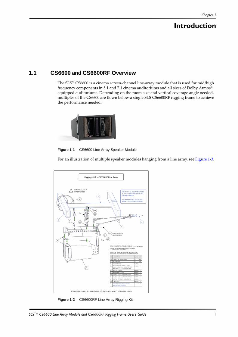
The SLS™ CS6600 is a cinema screen‐channel line‐array module that is used for mid/high frequency components in 5.1 and 7.1 cinema auditoriums and all sizes of Dolby Atmos® equipped auditoriums. Depending on the room size and vertical coverage angle needed, multiples of the CS6600 are flown below a single SLS CS6600RF rigging frame to achieve the performance needed.
Figure 1‐1
Figure 1-1 CS6600 Line Array Speaker Module
For an illustration of multiple speaker modules hanging from a line array, see Figure 1‐3.Figure 1‐2
Figure 1-2 CS6600RF Line Array Rigging Kit
Rigging Kit for CS6600RF Line Array
INSTALLER ASSUMES ALL RESPONSIBILITY AND ANY LIABILITY FOR INSTALLATION
ADAPTIVE C C-096 ADJ TENSION-COUPLER
ADAPTIVE SC-188-48-SS WIRE + SHACKLE
CABLE TI E 4”
2
1
6
3D
3E
3F
3G
4 STRUCTU RAL MOUNTI NG HARDWARE 0—
6600532
6600532
6600532
TOTAL WEIGHT OF 12 SPEAKER ASSEMBLY: 136 kg (300 lbs)
TRUSS CLAMP FOR SCHEDULE 40 PIPE MIN: 3.2 cm (1.2 5”) 4.2 cm (1.66”)OD TRUSSMAX: 3.8 cm (1.5 0”) 5.1 cm (2”) OD TRUSS
NUT 1/2”-1 3 NYLOC
WASH ER 5/8” I D S TEEL
ADAPTIVE SK-375 3/8” ANCHOR SHACKLE
QTYDESCRIPTIONITEM
1A
RIGGING F RAME
CS6600CF LINE ARR AY SPEAKER 9-1 6
3-48
1
1B
2
3A
3B
3C
1
1
1
1
RIGGING P INS
PART #
63 27994
—
—
6600532
6600532
6600532
6600532
NOT S UPPLIED B Y D OLBY
3F
3A3B
3C
4
3D3F4
1B
1A
1B
23G
3E
4
CABLE TI ES FORALL SHACKLES
STRUCTU RAL MOUNTING PARTS NOT SU PPLIED B Y DOLBY AR E SHO WN I N B LUE
USE APPROPRIATE PARTS FOR WEIGHT LOAD AND FOR WALL
! REMO VE SLACK IN SAFETY C ABLE
STRUCTU RAL MOUNTI NG HARDWARE NOT SUPPLIED BY DOLB Y MUST ALSO MEET 5:1 SAFET Y FACTOR OR GREATER
RIGGING KIT HARDWARE SUPPLIED BY DOLBY MEETS5:1 SAFETY FACTOR OR GREATER
SLS™ CS6600 Line Array Module and CS6600RF Rigging Frame User’s Guide 1
Introduction
Li
1
C
C
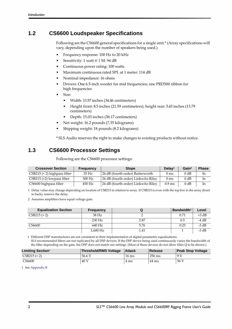
1.2 CS6600 Loudspeaker Specifications
Following are the CS6600 general specifications for a single unit.* (Array specifications will vary, depending upon the number of speakers being used.)
• Frequency response: 100 Hz to 20 kHz
• Sensitivity: 1 watt @ 1 M: 94 dB
• Continuous power rating: 100 watts
• Maximum continuous rated SPL at 1 meter: 114 dB
• Nominal impedance: 16 ohms
• Drivers: One 6.5‐inch woofer for mid frequencies; one PRD500 ribbon for high frequencies
• Size:
• Width: 13.57 inches (34.46 centimeters)
• Height front: 8.5 inches (21.59 centimeters); height rear: 5.43 inches (13.79 centimeters)
• Depth: 15.03 inches (38.17 centimeters)
• Net weight: 16.2 pounds (7.35 kilograms)
• Shipping weight: 18 pounds (8.2 kilograms)
* SLS Audio reserves the right to make changes to existing products without notice.
1.3 CS6600 Processor Settings
Following are the CS6600 processor settings:
Crossover Section Frequency Slope Delay1
1 Delay value may change depending on location of CSB215 in relation to array. If CSB215 is even with the top box in the array (front to back), remove the delay.
Gain2
2 Assumes amplifiers have equal voltage gain.
Phase
CSB215 (× 2) highpass filter 35 Hz 24 dB (fourth order) Butterworth 0 ms 0 dB In
CSB215 (×2) lowpass filter 300 Hz 24 dB (fourth order) Linkwitz‐Riley 0 ms 0 dB In
CS6600 highpass filter 450 Hz 24 dB (fourth order) Linkwitz‐Riley 0.9 ms 0 dB In
Equalization Section Frequency Q Bandwidth1
1 Different DSP manufactures are not consistent in their implementation of digital parametric equalizations. SLS recommended filters are not replicated by all DSP devices. If the DSP device being used continuously varies the bandwidth of the filter depending on the gain, the DSP does not match our settings. (Most of these devices do not allow filter Q to be shown.)
Level
CSB215 (× 2) 38 Hz 2 0.71 +3 dB
230 Hz 2.87 0.5 ‐4 dB
CS6600 640 Hz 5.76 0.25 ‐3 dB
1,600 Hz 1.41 1 ‐3 dB
miting Section1
See Appendix B
Threshold/RMS Voltage Attack Release Peak Stop Voltage
SB215 (× 2) 56.6 V 16 ms 256 ms 9 V
S6600 40 V 4 ms 64 ms 56 V
2 SLS™ CS6600 Line Array Module and CS6600RF Rigging Frame User’s Guide

CS6600RF Rigging Frame Specifications
1.4 CS6600RF Rigging Frame Specifications
Following are the CS6600RF general specifications*:
• No more than twenty CS6600s can be flown below the frame.
• Rigging frame vertical angle with the load suspended must be within +/‐ 15 degrees of zero degrees vertical.
• Center spar hole diameter for suspension rigging: 0.5 inches (12.7 mm).
• Corner hole diameter for horizontal aiming rigging: 0.5 inches (12.7 mm).
• Size:
• Width: 12.88 inches (327 millimeters)
• Height: 2.88 inches (73 millimeters)
• Depth: 14.66 inches (372.4 millimeters)
• Net weight: 5.96 pounds (2.7 kilograms).
* SLS Audio reserves the right to make changes to existing products without notice.Figure 1‐3
Figure 1-3 Setting the Rigging Frame Vertical Angle
12 SPEAKERS
< 5cm (2.0”)
SWAGING TI E BA CKS M UST B E AT LEAS T 5cm ABO VE TH E HOR IZONTAL P LANE OF TH E LINE AR RAY R IGGING F RAME S O THAT TH E VER TICAL ANGLE OF THE LI NE AR RAY I S NO T AFFECTED.
REFER T O SITE SP ECIFIC DOLB Y ATMOS ARCH ITECTU RAL ®
PLANS DOCU MENTS T O SE T EACH C ABINET ANGLE.
! REMO VE SL ACK I N SAFETY C ABLE.
±15°
VERTICAL ANGLE
SLS™ CS6600 Line Array Module and CS6600RF Rigging Frame User’s Guide 3

Chapter 2
Installing the SLS CS6600
2.1 Designing the Line Array System
The installer must use the EASE® Focus line array design software to determine the approved system configuration. The approved configuration identifies the optimum number of CS6600 modules required for the array and the acceptable mounting configuration on the rigging frame. The EASE Focus software, required design file plug‐in, and EASE Focus support documentation are available at no charge from the AFMG EASE Focus website at http://focus.afmg.eu/.
THE EASE FOCUS SOFTWARE IS PROVIDED ̋ AS ISʺ, WITHOUT WARRANTY OF ANY KIND, EXPRESS OR IMPLIED, INCLUDING BUT NOT LIMITED TO THE WARRANTIES OF MERCHANTABILITY, FITNESS FOR A PARTICULAR PURPOSE, TITLE AND NON‐INFRINGEMENT. IN NO EVENT SHALL DOLBY BE LIABLE FOR ANY DAMAGES OR OTHER LIABILITY, WHETHER IN CONTRACT, TORT OR OTHERWISE, ARISING FROM, OUT OF OR IN CONNECTION WITH THE SOFTWARE OR THE USE OR OTHER DEALINGS IN THE SOFTWARE.
2.2 CS600RF Array Assembly Overview
Before you begin the installation, you need the following documentation from EASE® Focus.
• Overall vertical and horizontal aiming angles of the array configuration.
• Overall array weight.
• SLS™ CS6600RF rigging frame recommended attachment point for installer‐supplied hardware to building structure for setting the vertical aiming angle of the array. This is provided as the hole number when counting from the front of the frame.
• The vertical articulation angles between each CS6600 loudspeaker, as specified on the sticker, which is located on the back rigging plate of each speaker cabinet.
• Overall suspension height of the array.
Warning: CONSULT A PROFESSONAL MECHANICAL OR STRUCTURAL ENGINEER
TO APPROVE ALL ATTACHMENTS TO BUILDING STRUCTURE. THIS APPARATUS MUST BE INSTALLED BY LICENSED AND INSURED PROFESSIONAL INSTALLERS. IF NOT INSTALLED ON THE BUILDING STRUCTURE PROPERLY, THIS APPARATUS COULD FALL, CAUSING PERSONAL INJURY OR DEATH. SUSPENSION OF HARDWARE COMPONENTS SHOULD BE CALCULATED WITH A GIVEN SAFETY FACTOR TO BE WITHIN THEIR RESPECTIVE WORKING LOAD LIMITS. INSPECT ALL COMPONENTS BEFORE INSTALLATION. THIS APPARATUS IS NOT INTENDED FOR ANY USE OTHER THAN SPECIFICALLY STIPULATED PREVIOUSLY IN THIS DOCUMENT. TO PREVENT INJURY, THIS APPARATUS MUST BE SECURELY ATTACHED TO THE CEILING OF THE BUILDING STRUCTURE. ALL LOCAL BUILDING AND SEISMIC CODES MUST BE ADHERED TO.
SLS™ CS6600 Line Array Module and CS6600RF Rigging Frame User’s Guide 5
Installing the SLS CS6600
2.2.1 Required Parts
Following are the parts required for the installation. Based on the weight of the array, installer‐supplied rigging hardware must have a minimum 5:1 safety factor, or greater if a higher requirement is mandated per local laws.
Figure 2‐1
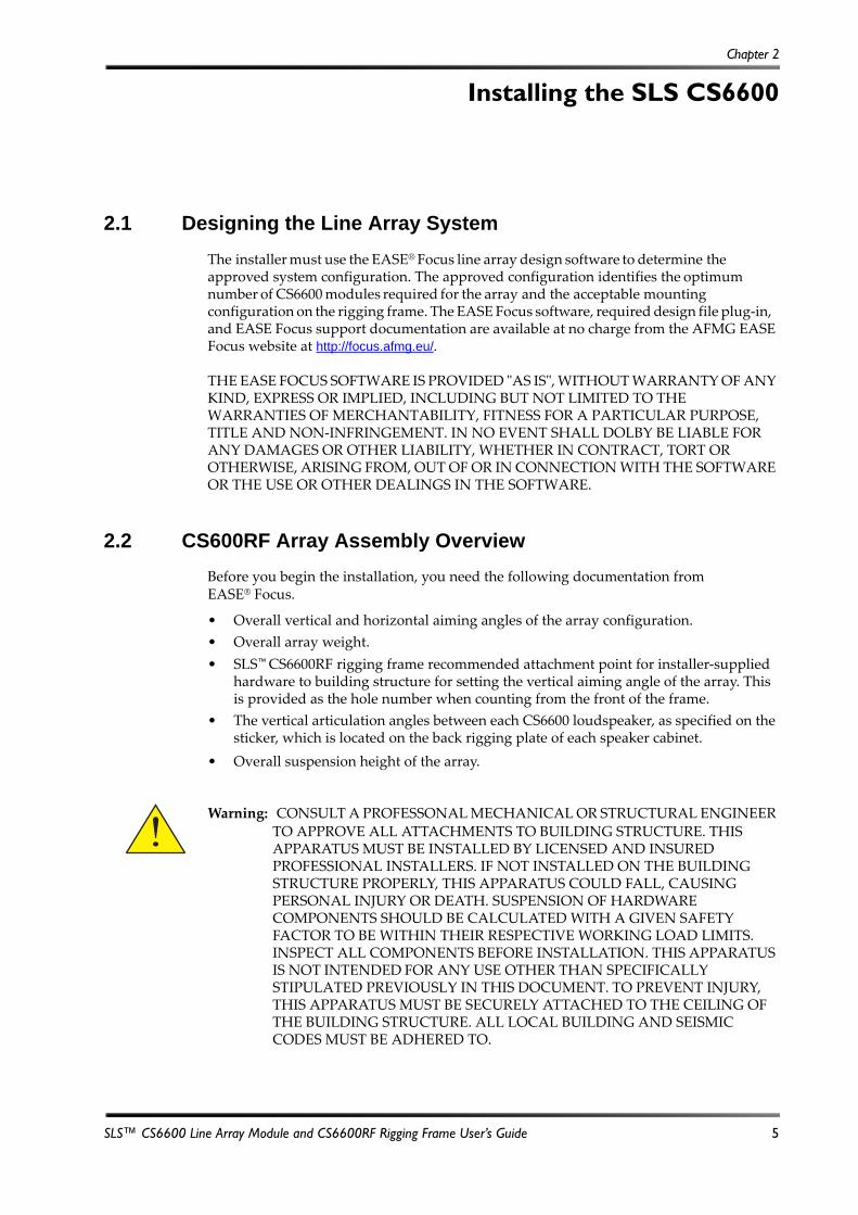
Figure 2-1 Required Parts
For an illustration of multiple speaker modules hanging from a line array, see Figure 1‐3.
2.2.2 Tools Required
• #2 Phillips screwdriver for attaching speaker wire to the barrier strip
2.2.3 Attaching CS6600RF to Building Structure with Installer-Supplied Hardware
To attach the CS6600RF to the building structure, use installer‐supplied rigging hardware. Safe overhead rigging practices require an understanding of the proper methods and are outside the scope of this manual. All installer‐supplied rigging hardware must have a minimum 5:1 safety factor based on the weight of the array, which is shown in the EASE
Focus data.
Warning: BASED ON THE ARRAY WEIGHT, INSTALLER‐SUPPLIED RIGGING
HARDWARE MUST HAVE A MINIMUM 5:1 SAFETY FACTOR, OR GREATER IF A HIGHER REQUIREMENT IS MANDATED PER LOCAL LAWS. USE ONLY THE CENTER SPAR IN THE FRAME FOR THE LOCATION OF THE SAFETY ATTACHMENT AND PRIMARY RIGGING ATTACHMENT. INSTALLER‐SUPPLIED SHACKLES MUST NOT TOUCH OTHER AREAS OF THE RIGGING FRAME WHEN THE LOAD IS SUSPENDED. RIGGING HOLES IN THE FRAME CORNERS MUST NOT BE USED FOR ANY LOAD SUSPENSION.
UUUUuSafety cable Primary rigging cable
Positive lock pin forarray assembly
Center spar for rigging attachment
CS6600 mid/high loudspeaker
CS6600RF rigging frame
For horizontal aiming attachment points (NOT foruse to suspend the load)
Front of rigging frame
6 SLS™ CS6600 Line Array Module and CS6600RF Rigging Frame User’s Guide
CS600RF Array Assembly Overview
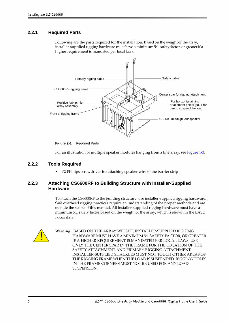
The rigging‐frame point of attachment for the installer‐supplied rigging hardware is provided in the EASE Focus data. We recommend flying the array from this specified rigging point, as it sets the overall vertical angle of the entire array from a single point. The hole numbers, as specified in EASE Focus data, start from the front of the rigging frame. Rigging hole diameters are ½ inch (12.7 mm).
The EASE Focus data also specifies the overall height of the array from the ground. The reference point on the array assembly for the height location is referenced to the top front edge of the CS6600RF. You need to clarify the building structure reference point with the system designer.
Figure 2‐2
Figure 2-2 Reference Point on Array for the EASE Focus Height Measurement
You can use any of the four holes located at the corners of the rigging frame to add pull points to aid in setting and holding any horizontal aiming angle that is required for the entire array. The hole diameter is ½ inch (12.7 mm). Do not use these four holes to suspend the load. Use the horizontal aiming attachment points only to turn the speaker, so it is facing the correct direction to provide the best coverage across the seats in the auditorium.
Figure 2‐3
Figure 2-3 Example of Installer-Provided Rigging Hardware Attached to CS6600RF and Horizontal Aiming Pull Points
Heightreference point
Points on frame for horizontal aiming only
SLS™ CS6600 Line Array Module and CS6600RF Rigging Frame User’s Guide 7
Installing the SLS CS6600
2.2.4 Attaching CS6600RF Safety Cable to Building Structure
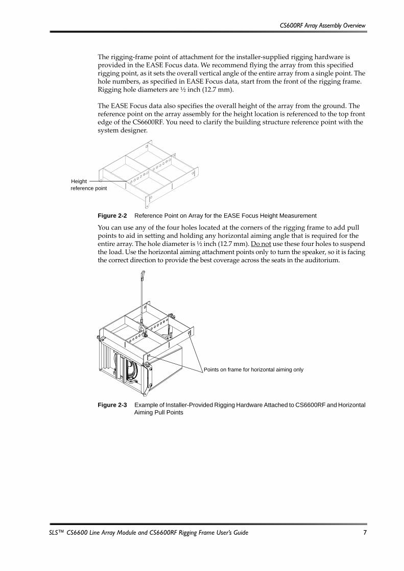
After the frame is rigged to the building structure, you must rig a secondary safety attachment point to an independent point on the building structure. You must use only rigging points on the center spar of the CS6600RF for attaching this safety rigging
hardware. All installer‐supplied rigging hardware must have a minimum 5:1 safety factor,
or greater if a higher requirement is mandated per local laws.
Figure 2‐4
Figure 2-4 Example of Safety Cable Attached from CS6600RF to Building Structure
2.2.5 Attaching CS6600 to CS6600RF
You attach the first CS6600 line array module in the array to the rigging frame using the three provided positive lock pins that are provided with the CS6600. The correct points for attachment are shown in the following figure.
To insert the pin:
1. Push the positive‐lock release button, which is located at the center of the pin back head.
2. Insert the pin into the hardware and release the button.
Warning: INSTALLER‐SUPPLIED RIGGING HARDWARE MUST HAVE A MINIMUM
SAFETY FACTOR BASED ON THE WEIGHT OF THE APPARATUS, INCLUDING THE CABLE AND ANY ATTACHMENT HARDWARE. YOU MUST SECURELY TIGHTEN THE HARDWARE AND PREVENT ACCIDENTAL UNSCREWING OR UNCOUPLING OF THE HARDWARE. REMOVE ALL SLACK FROM THE CABLE TO PREVENT ANY SHOCK LOADING THAT COULD CAUSE THE CABLE TO FAIL. REPLACE SAFETY CABLE AND HARDWARE IF IT HAS BEEN STRESSED BY A PRIMARY RIGGING FAILURE. USE ONLY THE CENTER SPAR IN THE FRAME FOR THE LOCATION OF THE SAFETY ATTACHMENT.
Safety cablePrimary rigging cable
8 SLS™ CS6600 Line Array Module and CS6600RF Rigging Frame User’s Guide
CS600RF Array Assembly Overview
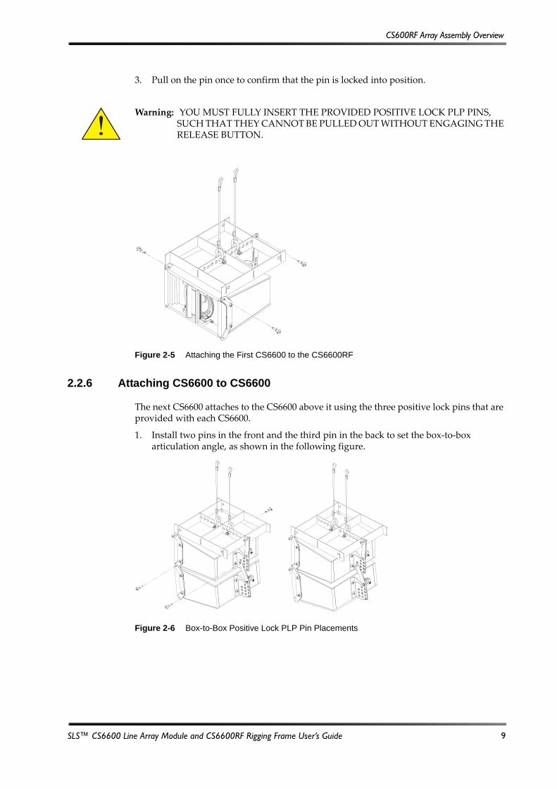
3. Pull on the pin once to confirm that the pin is locked into position.
Figure 2‐5
Figure 2-5 Attaching the First CS6600 to the CS6600RF
2.2.6 Attaching CS6600 to CS6600
The next CS6600 attaches to the CS6600 above it using the three positive lock pins that are provided with each CS6600.
1. Install two pins in the front and the third pin in the back to set the box‐to‐box articulation angle, as shown in the following figure.
Figure 2‐6
Figure 2-6 Box-to-Box Positive Lock PLP Pin Placements
Warning: YOU MUST FULLY INSERT THE PROVIDED POSITIVE LOCK PLP PINS, SUCH THAT THEY CANNOT BE PULLED OUT WITHOUT ENGAGING THE RELEASE BUTTON.
SLS™ CS6600 Line Array Module and CS6600RF Rigging Frame User’s Guide 9
Installing the SLS CS6600
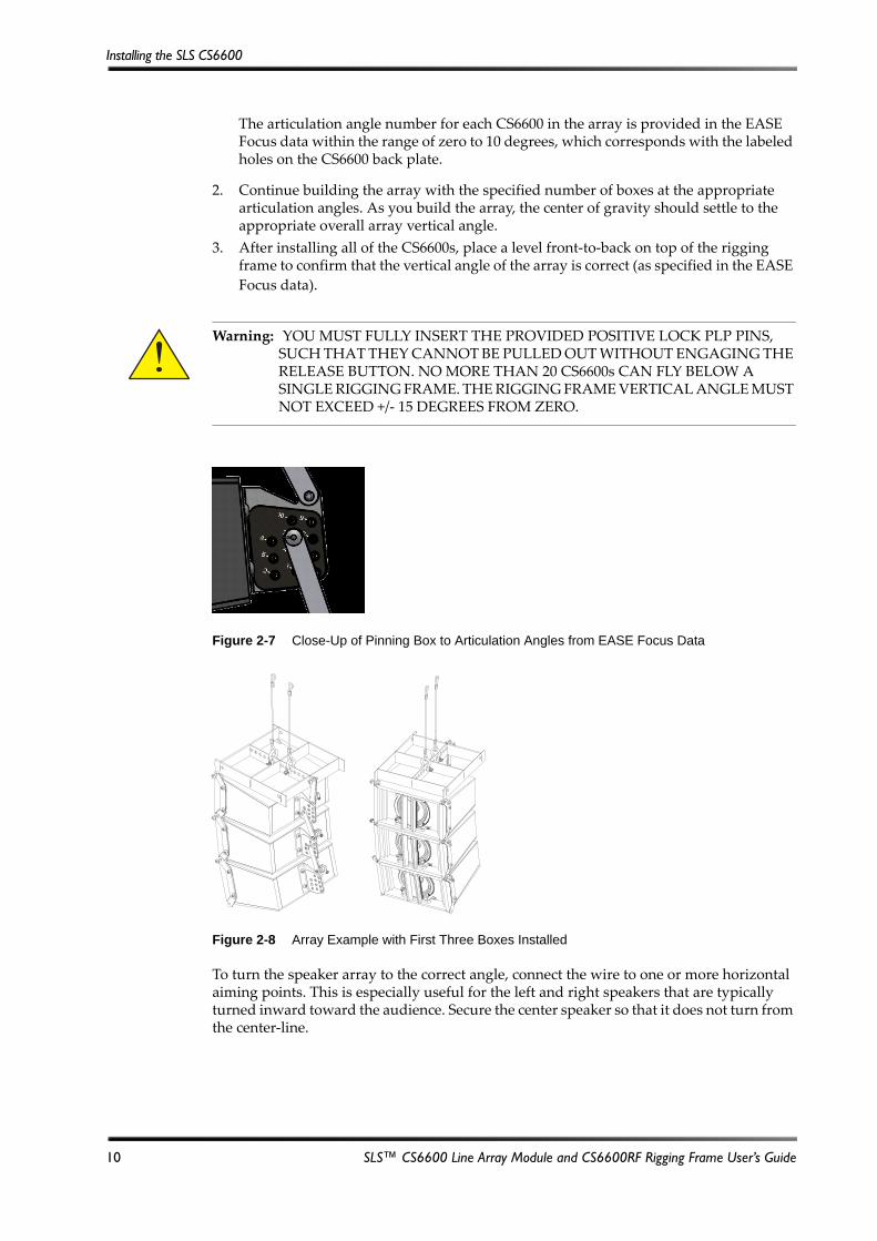
The articulation angle number for each CS6600 in the array is provided in the EASE Focus data within the range of zero to 10 degrees, which corresponds with the labeled holes on the CS6600 back plate.
2. Continue building the array with the specified number of boxes at the appropriate articulation angles. As you build the array, the center of gravity should settle to the appropriate overall array vertical angle.
3. After installing all of the CS6600s, place a level front‐to‐back on top of the rigging frame to confirm that the vertical angle of the array is correct (as specified in the EASE
Focus data).
Figure 2‐7
Figure 2-7 Close-Up of Pinning Box to Articulation Angles from EASE Focus Data
Figure 2‐8
Figure 2-8 Array Example with First Three Boxes Installed
To turn the speaker array to the correct angle, connect the wire to one or more horizontal aiming points. This is especially useful for the left and right speakers that are typically turned inward toward the audience. Secure the center speaker so that it does not turn from the center‐line.
Warning: YOU MUST FULLY INSERT THE PROVIDED POSITIVE LOCK PLP PINS, SUCH THAT THEY CANNOT BE PULLED OUT WITHOUT ENGAGING THE RELEASE BUTTON. NO MORE THAN 20 CS6600s CAN FLY BELOW A SINGLE RIGGING FRAME. THE RIGGING FRAME VERTICAL ANGLE MUST NOT EXCEED +/‐ 15 DEGREES FROM ZERO.
10 SLS™ CS6600 Line Array Module and CS6600RF Rigging Frame User’s Guide
Connecting Audio
2.3 Connecting Audio
Connect the speaker wires to the input barrier strip using a #2 Phillips screwdriver. The input barrier strip accepts 16‐ to 12‐gauge wire, with either spade lugs or bare wire. Always use industry‐standard practice for selecting wire gauge based on the product power rating and cable length. Note that the barrier strip is marked with plus (+) or red indicators to show the polarity. Per IEC standard, a positive voltage on the positive marked input results in the low‐frequency driver(s) moving outwards. Always tie down the cable to available
hardware to minimize any buzzing or pullouts.
If possible, play sound through the speaker to identify any connection issues, buzzing, or rattling.
Warning: AMPLIFIERS SHOULD BE TURNED OFF WHEN CONNECTING THE LOUDSPEAKER WIRING.
SLS™ CS6600 Line Array Module and CS6600RF Rigging Frame User’s Guide 11
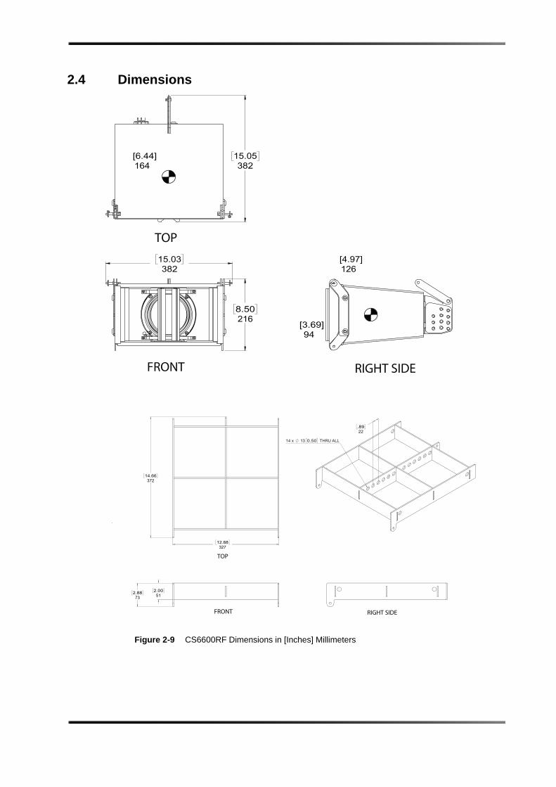
2.4 DimensionsFigure 2‐9
Figure 2-9 CS6600RF Dimensions in [Inches] Millimeters
FRONT
TOP
RIGHT SIDE
FRONT RIGHT SIDE
TOP
A2 ALL DIMENSIONS ARE IN MILLIMETERS
12345678
B B
C C
D D
E E
F F
Appendix A
Environmental Compliance and Regulations
A.1 EU Environmental Regulations and Compliance
Following are the CS6600 EU environmental regulations and compliance information.
Restriction of Hazardous Substances Directive (RoHS)
All Dolby® products comply with the requirements of the EU RoHS Directive. For the Dolby Declarations of Conformity, go to http://www.dolby.com/us/en/about/environmental-commitment.html.
Product End-of-Life Information
This product is electronic equipment and should be disposed of in accordance with all applicable laws. Do not dispose as household waste. Do not dispose of the product in a fire. Please dispose of this product by taking it to your local electronic waste collection point or recycling center. For information regarding where to recycle electronic equipment, contact your local dealer. For additional information regarding Waste Electrical and Electronic Equipment (WEEE) and product disposal go to http://www.dolby.com/us/en/about/environmental-commitment.html
A.2 Russian Environmental Regulations and Compliance
Following is the CS6600 Russian environmental compliance information.
Restriction of Hazardous Substances (RoHS) Directive
This product complies with Russian EAC RoHS requirements.Figure A‐1
SLS™ CS6600 Line Array Module and CS6600RF Rigging Frame User’s Guide 13


Appendix B
Setting System Limiters
B.1 Setting up System Limiters
This documentation explains how to set up system limiters to protect your loudspeaker and provide maximum performance when the digital signal processor (DSP), amplifier, and loudspeaker hardware are all variables. The following procedure provides a limiter setting threshold that can protect loudspeakers in a majority of use cases. However, the speaker drivers may still be vulnerable to content issues, such as sustained feedback or large, low‐frequency transients below box tuning. Good system design and common sense should be the rule.
1. Obtain an audio source (to generate pink noise) and a true RMS voltage meter with a bandwidth of at least 20 kHz that can average a reading over a period of at least 10 seconds.
2. Complete the room tuning and set the amplifier gain.
To prevent future user error, consider setting the amplifiers at full gain, unless the amplifier gain setting is hardware or software protected. In such a case, you can optimize the amplifier gain to achieve the best signal‐to‐noise ratio.
3. After completing the room tuning and setting the amplifier gain, bypass the limiter on the DSP that you are using for protection, and leave all other DSP functions for that output engaged. For example, the highpass filter, crossovers, equalization, and so on.
4. Mute all system outputs except the output that is currently being calibrated.
5. Place the voltage meter across the amplifier +/‐ output terminals and turn up the pink noise source until the reading on the meter is slightly above the specified Threshold/RMS voltage rating for that speaker driver and its recommended processor settings (see Section 1.3).
6. Play the pink noise only long enough to obtain a stable RMS average voltage reading For high‐frequency drivers, this is typically five seconds, and for full range loudspeakers or subwoofers, it is typically ten seconds.
7. Set the limiter to a minimum ratio of 100:1, and then input the attack and release times recommended by the speaker manufacturer.
8. Engage the limiter, and decrease the threshold until the voltage is lowered to the specified rating, without changing the pink noise gain.
9. Repeat the above procedure for each driver and/or passive loudspeaker you are using.
10. If a predictive peak stop limiter is available on the DSP, engage it at 6 dB above the RMS setting.
11. Monitor for amplifier clipping. If clipping occurs during system use, lower the peak‐stop threshold until the amplifier clips slightly. Alternatively, you can engage the self‐contained limiter circuit in the amplifier (if it has such a limiter circuit).
You need to perform this procedure only once, as long as the combined amplifier‐limiter does not change. However, amplifier gain changes modify the limiter action. If the amplifier gain is decreased, protection engages early, which limits driver output. If the amplifier gain is increased, protection engages only after the driver reading is above the safe RMS voltage.
SLS™ CS6600 Line Array Module and CS6600RF Rigging Frame User’s Guide 15


![[Array, Array, Array, Array, Array, Array, Array, Array, Array, Array, Array, Array]](https://static.fdocuments.net/doc/165x107/56816460550346895dd63b8b/array-array-array-array-array-array-array-array-array-array-array.jpg)