Slim Body with Automatic Sensitivity Setting set sensitivity. Press the “ON” button with an...
23
PHOTOELECTRIC SENSOR Amplifier Built-in Type RX RX-LS200 EX-40 EQ-30 EQ-20 EX-10 CX-ND300R CX-30 CX-20 FX-11A FX-10 FZ-10 Number of blinks Margin (%) Margin near by threshold level 0 1 2 3 4 5 Under 15 15 30 30 45 45 60 60 75 Over 75 ( ) to to to to Compact Size with Advanced Sensing Technology FX-7 SERIES Slim Body with Automatic Sensitivity Setting Marked Conforming to EMC directive Fiber Sensor FX-7 Just 10mm thick. Even a number of FX-7 amplifiers save space. Thickness : 10mm Automatic Sensitivity Setting The standard M4 fiber offers the sensing range of 600mm. Anyone can set on optimum sensitivity by just pressing buttons. Even if its power is turned off, the EEPROM memory saves your set sensitivity. Press the “ON” button with an object Long Sensing Range W10H31.5D59mm The FX-7 amplifier performs precise and accurate sensing 8 times greater than a conventional model. It can be used not only to detect the presence of an object, but also to discriminate color, or find a thin film overlap. Complicated and sophisticated appli- cation needs are relied on the FX-7. The FX-7 series also provides the green LED amplifier that is eligible for appliations much delicate. Sensitivity : 8 Times Higher than Before If either one of the Light state or the Dark state is unstable but the other is stationary, the threshold level can be shifted from the center between the set ON and OFF levels to the stationary side. Sensitivity Shift The number of blinks of the stability indicator represents the stability margin that you have set the sensitivity. Stability Margin Indication 600mm 160mm 14.5m Reflective mode M4 standard • long sensing range fiber FT-B8 M6 standard • long sensing range fiber FD-B8 With lens attachments (FX-LE2FT-FM10) Thru-beam mode Only 100mm wide with 10 units Press the “OFF” button with no object Easily detects translucent film overlap. Phone: 800.894.0412 - Fax: 888.723.4773 - Web: www.clrwtr.com - Email: [email protected]
Transcript of Slim Body with Automatic Sensitivity Setting set sensitivity. Press the “ON” button with an...
PHOT
OELE
CTRI
C SE
NSOR
Am
plif
ier
Bu
ilt-i
n T
ype
RX
RX
-LS
200
EX
-40
EQ
-30
EQ
-20
EX
-10
CX-N
D300
RC
X-3
0C
X-2
0F
X-1
1AF
X-1
0F
Z-1
0
Number of blinks
Margin (%) Margin near by threshold level
0 1 2 3 4 5
Under15
15
30
30
45
45
60
60
75Over75( )
to toto to
Compact Size withAdvanced SensingTechnology
FX-7 SERIES
Slim Body with Automatic Sensitivity Setting
MarkedConforming to EMC directive
Fib
er S
enso
rF
X-7
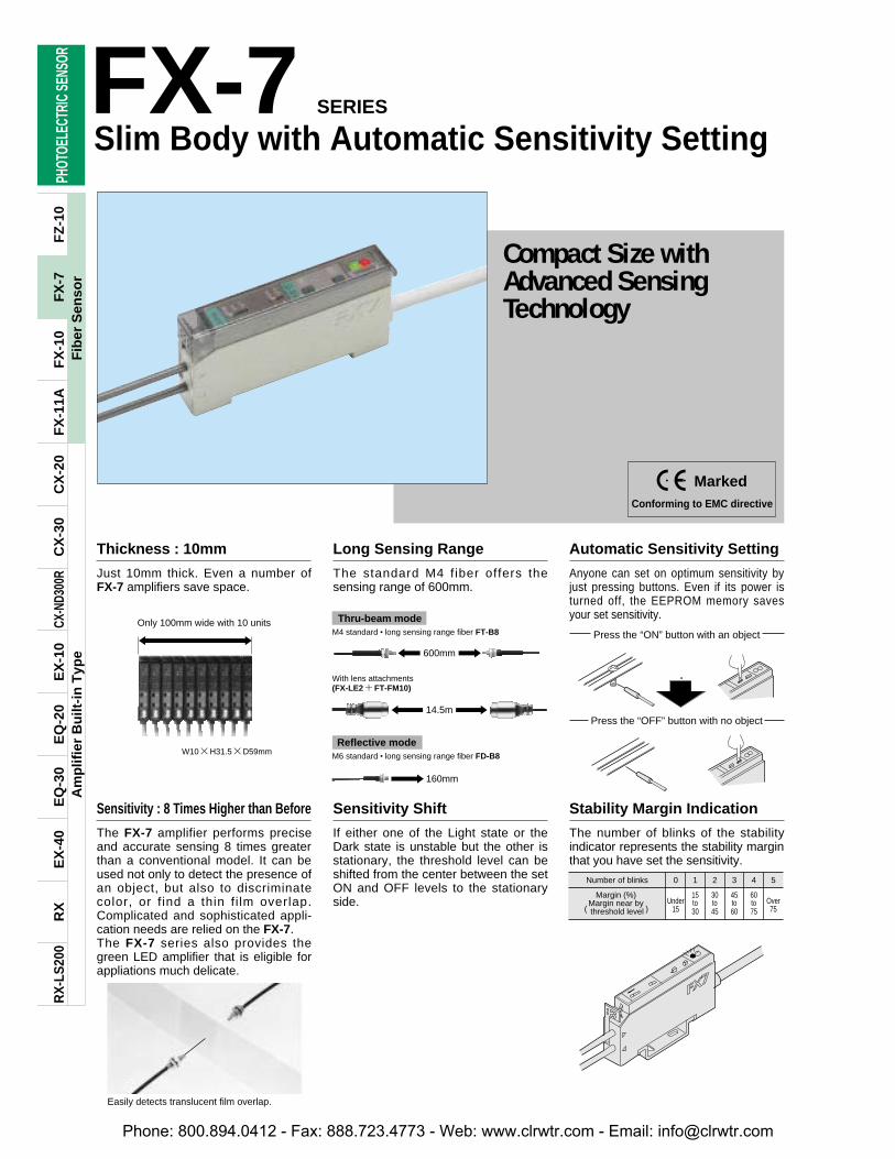
Just 10mm thick. Even a number ofFX-7 amplifiers save space.
Thickness : 10mm Automatic Sensitivity Setting
The standard M4 fiber offers thesensing range of 600mm.
Anyone can set on optimum sensitivity byjust pressing buttons. Even if its power isturned off, the EEPROM memory savesyour set sensitivity.
Press the “ON” button with an object
Long Sensing Range
W10H31.5D59mm
The FX-7 amplifier performs preciseand accurate sensing 8 times greaterthan a conventional model. It can beused not only to detect the presence ofan object, but also to discriminatecolor, or f ind a thin f i lm overlap.Complicated and sophisticated appli-cation needs are relied on the FX-7.The FX-7 series also provides thegreen LED amplifier that is eligible forappliations much delicate.
Sensitivity : 8 Times Higher than Before
If either one of the Light state or theDark state is unstable but the other isstationary, the threshold level can beshifted from the center between the setON and OFF levels to the stationaryside.
Sensitivity Shift
The number of blinks of the stabilityindicator represents the stability marginthat you have set the sensitivity.
Stability Margin Indication
600mm
160mm
14.5m
Reflective mode
M4 standard • long sensing range fiber FT-B8
M6 standard • long sensing range fiber FD-B8
With lens attachments(FX-LE2FT-FM10)
Thru-beam modeOnly 100mm wide with 10 units
Press the “OFF” button with no object
Easily detects translucent film overlap.
Phone: 800.894.0412 - Fax: 888.723.4773 - Web: www.clrwtr.com - Email: [email protected]
PHOT
OELE
CTRI
C SE
NSOR
Am
plif
ier
Bu
ilt-i
n T
ype
RX
RX
-LS
200
EX
-40
EQ
-30
EQ
-20
EX
-10
CX-N
D300
RC
X-3
0C
X-2
0F
X-1
1AF
X-1
0F
Z-1
0
Glass board cassette
Glass board
FD-L41
ON
ON
OFF
OFF
Approx.40ms
Normaloperation
Timeroperation
Synchronizingsensor
Sensor fordetection
Sensingoutput
Externalsynchronization
input
FX-MR3
FD-EG1
FT-KV2
PLC, switch, etc.
Blue
Violet Violet
Blue
PinkPLC, switch, etc.
Wafer
FD-L42
Vacuumchamber
FT-6V
FT-J6
FV-BR1
FD-AFM2E
FX-7
37
Fib
er S
enso
rF
X-7
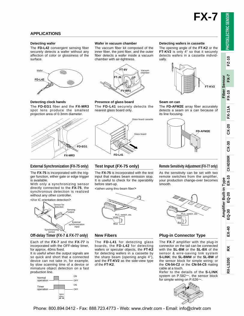
APPLICATIONS
Detecting waferThe FD-L42 convergent sensing fibersecurely detects a wafer without anyaffection of color or glossiness of thesurface.
Wafer in vacuum chamberThe vaccum fiber kit composed of theinner fiber, the joint fiber, and the outerfiber detects a wafer inside a vacuumchamber with air-tightness.
Detecting wafers in cassetteThe opening angle of the FT-K2 or theFT-KV2 is only 4 so that it securelydetects wafers in a cassette individ-ually.
Detecting clock handsThe FD-EG1 fiber and the FX-MR3spot lens produce the smallestprojection area of 0.3mm diameter.
Presence of glass boardThe FD-L41 securely detects thenearest glass board only.
Seam on canThe FD-AFM2E array fiber accuratelydetects a seam on a can because ofits line focusing.
The FX-75 is incorporated with the trig-ger function, either gate or edge triggeris available.With only a synchronizing sensordirectly connected to the FX-75, thesynchronous detection is realizedwithout any other controller.
External Synchronization (FX-75 only)
Each of the FX-7 and the FX-77 isincorporated with the OFF-delay timer,for approx. 40ms fixed.It is useful when the output signals areso quick and short that a connecteddevice can not take in, for example,by slow scanning time of a device orminiature object detection on a fastproduction line.
Off-delay Timer (FX-7 & FX-77 only)
<For IC orientation detection>
The FX-75 is incorporated with the testinput that makes beam emission stop.It is useful to check for the operabilitybefore start-up.
Test Input (FX-75 only)
The FD-L41 for detecting glassboards, the FD-L42 for detectingwafers or specular objects, the FT-K2for detecting wafers in a cassette bythe sharp beam (opening angle 4),and the FT-KV2 as the side-view typeof the FT-K2.
New Fibers
<When using thru-beam fiber>
As the sensitivity can be set with tworemote switches from the amplifier,your production change-over becomessmooth.
Remote Sensitivity Adjustment (FX-77 only)
The FX-7 amplifier with the plug-inconnector on the tail can be connectedwith the SL-BM or the SL-BX of thesensor & wire-saving l ink systemS-LINK; the SL-BMW or the SL-BW ofthe sensor block for simple wiring; orthe CN-54-C2 or the CN-54-C5 matingcable at a touch.Refer to the details of the S-LINKsystem on P.582l, the sensor blockfor simple wiring on P.626l.
Plug-in Connector Type
Phone: 800.894.0412 - Fax: 888.723.4773 - Web: www.clrwtr.com - Email: [email protected]
M4
M4
M4
"1.48
"2.5
M3
M3
M3
"0.88
"1.5
M4
M4
M3
"1.5
M4
"2.1
M4
M4
M4
"5.5
"5.5
M4
PHOT
OELE
CTRI
C SE
NSOR
Am
plif
ier
Bu
ilt-i
n T
ype
RX
RX
-LS
200
EX
-40
EQ
-30
EQ
-20
EX
-10
CX-N
D300
RC
X-3
0C
X-2
0F
X-1
1AF
X-1
0F
Z-1
0
2mFree Cut
2mFree Cut
2mFree Cut
2mFree Cut
2mFree Cut
2mFree Cut
Min. sensing object[on optimum condition (*2)]
[ : Red LED type: Green LED type ]
Sensing range (*1): Red LED type: Green LED type
Min. sensing object[on optimum condition (*2)]
[ : Red LED type: Green LED type ]
Fiber cablelength
Fiber cablelength
Sensing range (*1): Red LED type: Green LED type
Type Shape of fiber head (mm) Features Model No.
FT-NFM2
FT-SNFM2
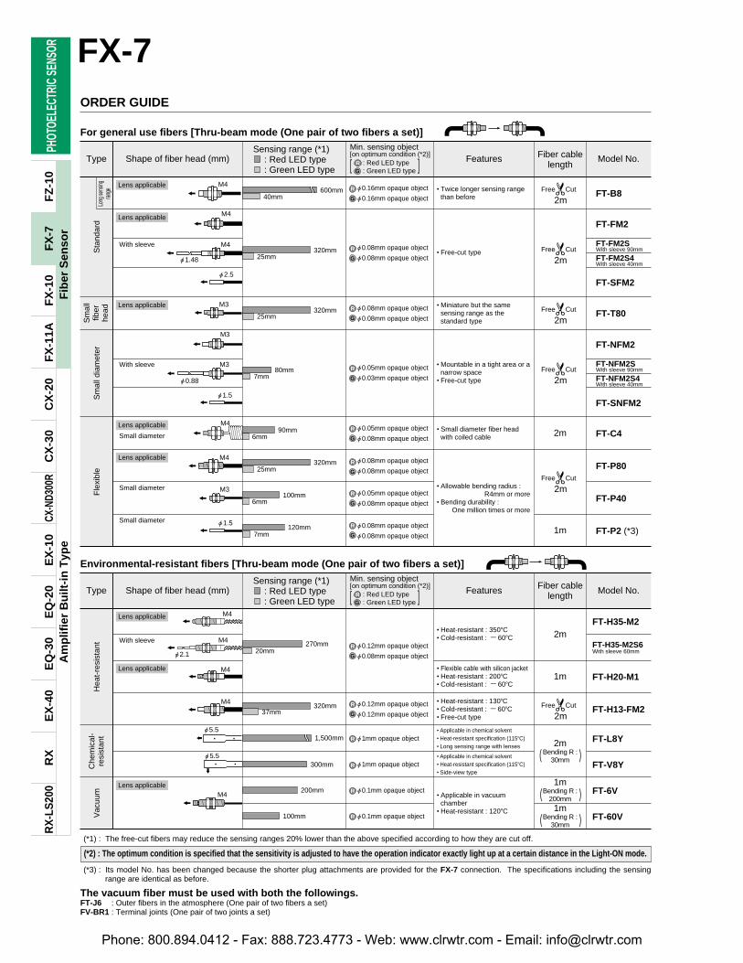
For general use fibers [Thru-beam mode (One pair of two fibers a set)]
FX-7
38
Fib
er S
enso
rF
X-7
ORDER GUIDE
"0.16mm opaque object
"0.16mm opaque object
"0.08mm opaque object
"0.08mm opaque object
"0.08mm opaque object
"0.08mm opaque object
"0.05mm opaque object
"0.08mm opaque object
"0.08mm opaque object
"0.08mm opaque object
"0.05mm opaque object
"0.08mm opaque object
"0.08mm opaque object
"0.08mm opaque object
"0.05mm opaque object
"0.03mm opaque object
• Twice longer sensing rangethan before
• Miniature but the samesensing range as thestandard type
• Small diameter fiber headwith coiled cable 2m
1m
2m
1m
2mBending R :
30mm
• Allowable bending radius :R4mm or more
• Bending durability : One million times or more
• Mountable in a tight area or anarrow space
• Free-cut type
• Free-cut type
600mm
Sta
ndar
dS
mal
lfib
erhe
adF
lexi
ble
Sm
all d
iam
eter
Long
sens
ingran
ge FT-B8
FT-FM2
FT-SFM2
FT-FM2SWith sleeve 90mm
FT-FM2S4With sleeve 40mm
FT-NFM2SWith sleeve 90mm
FT-NFM2S4With sleeve 40mm
FT-T80
FT-C4
FT-P80
FT-P40
FT-P2 (*3)
40mm
320mm25mm
320mm25mm
80mm7mm
90mm6mm
320mm25mm
100mm6mm
120mm7mm
Environmental-resistant fibers [Thru-beam mode (One pair of two fibers a set)]
"0.12mm opaque object
"0.08mm opaque object
"0.12mm opaque object
"0.12mm opaque object
"1mm opaque object
"1mm opaque object
"0.1mm opaque object
"0.1mm opaque object
• Heat-resistant : 350C• Cold-resistant : 60C
• Heat-resistant : 130C• Cold-resistant : 60C• Free-cut type
• Applicable in chemical solvent• Heat-resistant specification (115C)• Long sensing range with lenses
• Applicable in chemical solvent• Heat-resistant specification (115C)• Side-view type
• Applicable in vacuumchamber
• Heat-resistant : 120C
• Flexible cable with silicon jacket• Heat-resistant : 200C• Cold-resistant : 60C
Type Shape of fiber head (mm) Features Model No.
270mm
Vac
uum
Hea
t-re
sist
ant
Che
mic
al-
resi
stan
t
FT-H35-M2
FT-H20-M1
FT-H13-FM2
FT-L8Y
FT-V8Y
FT-6V
FT-60V
FT-H35-M2S6With sleeve 60mm20mm
320mm37mm
1,500mm
300mm
200mm
100mm
( )
1mBending R :
200mm )(1m
Bending R :30mm )(
(*1) : The free-cut fibers may reduce the sensing ranges 20% lower than the above specified according to how they are cut off.
(*3) : Its model No. has been changed because the shorter plug attachments are provided for the FX-7 connection. The specifications including the sensingrange are identical as before.
The vacuum fiber must be used with both the followings.FT-J6 : Outer fibers in the atmosphere (One pair of two fibers a set)FV-BR1 : Terminal joints (One pair of two joints a set)
RG
R
G
R
G
R
G
R
G
R
G
R
G
R
G
R
G
R
G
R
G
R
R
R
R
With sleeve
With sleeve
With sleeve
Small diameter
Small diameter
Small diameter
RG
Lens applicable
Lens applicable
Lens applicable
Lens applicable
Lens applicable
Lens applicable
Lens applicable
Lens applicable
(*2) : The optimum condition is specified that the sensitivity is adjusted to have the operation indicator exactly light up at a certain distance in the Light-ON mode.
Phone: 800.894.0412 - Fax: 888.723.4773 - Web: www.clrwtr.com - Email: [email protected]
M14
"2.5
15
15
M4
"1
("2 for FT-V22)"2.50.6
0.8
"1.5 "2.5
"3"0.4
"0.5 "3
"3
"3
M3"1
PHOT
OELE
CTRI
C SE
NSOR
Am
plif
ier
Bu
ilt-i
n T
ype
RX
RX
-LS
200
EX
-40
EQ
-30
EQ
-20
EX
-10
CX-N
D300
RC
X-3
0C
X-2
0F
X-1
1AF
X-1
0F
Z-1
0
7,000mm
1,000mm
600mm60mm
210mm20mm
180mm20mm
210mm24mm
85mm
45mm
120mm
5mm
24mm
12mm
650mm
275mm
120mm
45mm
10mFree Cut
2mFree Cut
2mFree Cut
2mFree Cut
2mFree Cut
FX-7
39
Fib
er S
enso
rF
X-7
Min. sensing object[on optimum condition (*2)]
[ : Red LED type: Green LED type ]
Sensing range (*1): Red LED type: Green LED type
Type Shape of fiber head (mm) Features Model No.
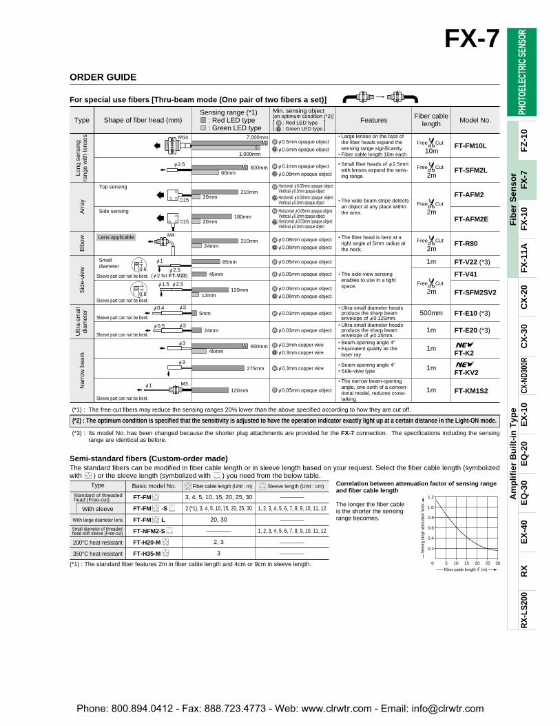
For special use fibers [Thru-beam mode (One pair of two fibers a set)]
ORDER GUIDE
"0.5mm opaque object
"0.5mm opaque object
"0.1mm opaque object
"0.08mm opaque object
"0.08mm opaque object
"0.08mm opaque object
"0.05mm opaque object
"0.08mm opaque object
"0.3mm copper wire
"0.3mm copper wire
"0.3mm copper wire
"0.05mm opaque object
"0.01mm opaque object
"0.03mm opaque object
"0.05mm opaque object
"0.05mm opaque object
Horizontal "0.05mm opaque objectVertical "0.3mm opaque objectHorizontal "0.03mm opaque objectVertical "0.3mm opaque object
Horizontal "0.05mm opaque objectVertical "0.3mm opaque objectHorizontal "0.03mm opaque objectVertical "0.3mm opaque object
• Large lenses on the tops ofthe fiber heads expand thesensing range significantly.
• Fiber cable length 10m each
• Small fiber heads of "2.5mmwith lenses expand the sens-ing range.
• The wide beam stripe detectsan object at any place withinthe area.
• The fiber head is bent at aright angle of 5mm radius atthe neck.
• The side-view sensingenables to use in a tightspace.
• Ultra-small diameter headsproduce the sharp beamenvelope of "0.125mm.
• Ultra-small diameter headsproduce the sharp beamenvelope of "0.25mm.
1m
1m
1m
1m
1m
500mm
• Beam-opening angle 4• Equivalent quality as thelaser ray
• Beam-opening angle 4• Side-view type
• The narrow beam-openingangle, one-sixth of a conven-tional model, reduces cross-talking.
Ultr
a-sm
all
diam
eter
Long
sen
sing
rang
e w
ith le
nses
Nar
row
bea
mS
ide-
view
Elb
owA
rray
FT-FM10L
FT-SFM2L
FT-AFM2
FT-AFM2E
FT-R80
FT-V22 (*3)
FT-V41
FT-SFM2SV2
FT-E10 (*3)
FT-E20 (*3)
FT-K2
FT-KV2
FT-KM1S2
(*1) : The free-cut fibers may reduce the sensing ranges 20% lower than the above specified according to how they are cut off.
(*3) : Its model No. has been changed because the shorter plug attachments are provided for the FX-7 connection. The specifications including the sensingrange are identical as before.
R
G
R
G
R
G
R
R
R
G
R
G
G
R
G
R
R
R
R
R
Fiber cablelength
Top sensing
Side sensing
Smalldiameter
RG
Lens applicable
Sleeve part can not be bent.
Sleeve part can not be bent.
Sleeve part can not be bent.
Sleeve part can not be bent.
Sleeve part can not be bent.
(*1) : The standard fiber features 2m in fiber cable length and 4cm or 9cm in sleeve length.
Basic model No.
FT-FM
FT-FM -S
FT-FM L
FT-NFM2-S
FT-H20-M
FT-H35-M
Fiber cable length (Unit : m)
3, 4, 5, 10, 15, 20, 25, 30
2 (*1), 3, 4, 5, 10, 15, 20, 25, 30
20, 30
2, 3
3
Sleeve length (Unit : cm)
1, 2, 3, 4, 5, 6, 7, 8, 9, 10, 11, 12
1, 2, 3, 4, 5, 6, 7, 8, 9, 10, 11, 12
Type
Standard of threadedhead (Free-cut)
With sleeve
With large diameter lens
Small diameter of threaded head with sleeve (Free-cut)
200°C heat-resistant
350°C heat-resistant
The standard fibers can be modified in fiber cable length or in sleeve length based on your request. Select the fiber cable length (symbolizedwith ) or the sleeve length (symbolized with ) you need from the below table.
Correlation between attenuation factor of sensing rangeand fiber cable length
The longer the fiber cable is the shorter the sensingrange becomes.
Semi-standard fibers (Custom-order made)
5 10 15 200
0.4
0.8
0.2
0.6
1.2
1.0
25 30
Sens
ing
rang
e at
tenu
atio
n fa
ctor
Fiber cable length # (m)
(*2) : The optimum condition is specified that the sensitivity is adjusted to have the operation indicator exactly light up at a certain distance in the Light-ON mode.
Phone: 800.894.0412 - Fax: 888.723.4773 - Web: www.clrwtr.com - Email: [email protected]
M6
M6
"2.8
M6
M6
M6
M6
M6
M6
"2.5
M4
M3
"3
M4
M4
"1.48
"2.5
M6
M3
"1.5
PHOT
OELE
CTRI
C SE
NSOR
Am
plif
ier
Bu
ilt-i
n T
ype
RX
RX
-LS
200
EX
-40
EQ
-30
EQ
-20
EX
-10
CX-N
D300
RC
X-3
0C
X-2
0F
X-1
1AF
X-1
0F
Z-1
0
160mm14mm
130mm8mm
130mm8mm
130mm8mm
30mm2mm
80mm
8mm
6mm
15mm1mm
30mm2.5mm
2mFree Cut
2mFree Cut
2mFree Cut
2mFree Cut
2mFree Cut
2mFree Cut
FX-7
40
Fib
er S
enso
rF
X-7
Min. sensing object[at the maximum sensitivity (*3)]
[ : Red LED type: Green LED type ]
Sensing range (*1) (*2): Red LED type: Green LED type
Type Shape of fiber head (mm) Features Model No.
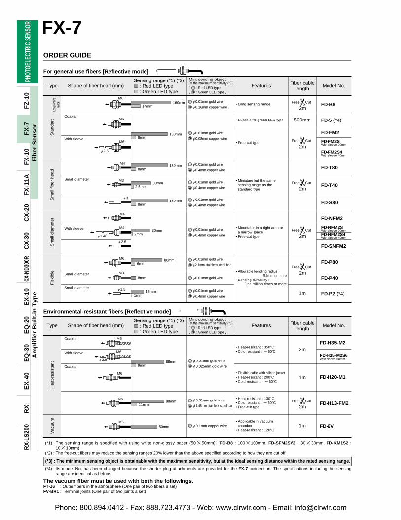
For general use fibers [Reflective mode]
ORDER GUIDE
"0.01mm gold wire
"0.16mm copper wire
"0.01mm gold wire
"0.08mm copper wire
"0.01mm gold wire
"0.4mm copper wire
"0.01mm gold wire
"0.4mm copper wire
"0.01mm gold wire
"0.4mm copper wire
"0.01mm gold wire
"0.4mm copper wire
"0.01mm gold wire
"0.4mm copper wire
"0.01mm gold wire
"2.1mm stainless steel bar
"0.01mm gold wire
• Long sensing range
• Suitable for green LED type
• Free-cut type
• Miniature but the samesensing range as thestandard type
• Mountable in a tight area ora narrow space
• Free-cut type
• Allowable bending radius :R4mm or more
• Bending durability : One million times or more
500mm
1m
Sta
ndar
dLo
ng se
nsing
range FD-B8
FD-5 (*4)
FD-FM2
FD-FM2SWith sleeve 90mm
FD-FM2S4With sleeve 40mm
FD-NFM2
FD-SNFM2
FD-P80
FD-P40
FD-P2 (*4)
FD-NFM2SWith sleeve 90mmFD-NFM2S4With sleeve 40mm
FD-T80
FD-T40
FD-S80
Fle
xibl
eS
mal
l dia
met
erS
mal
l fib
er h
ead
Min. sensing object[at the maximum sensitivity (*3)]
[ : Red LED type: Green LED type ]
Sensing range (*1) (*2): Red LED type: Green LED type
2m
1m
Environmental-resistant fibers [Reflective mode]
"0.01mm gold wire
"0.025mm gold wire
"0.01mm gold wire
"1.45mm stainless steel bar
"0.1mm copper wire
• Heat-resistant : 350C• Cold-resistant : 60C
• Heat-resistant : 130°C• Cold-resistant : 60°C• Free-cut type
• Applicable in vacuumchamber
• Heat-resistant : 120C
• Flexible cable with silicon jacket• Heat-resistant : 200C• Cold-resistant : 60C
88mm
Vac
uum
Hea
t-re
sist
ant
FD-H35-M2
FD-H20-M1
FD-H13-FM2
FD-6V
FD-H35-M2S6With sleeve 60mm
9mm
88mm
50mm
11mm
1m
(*1) : The sensing range is specified with using white non-glossy paper (5050mm). (FD-B8 : 100100mm, FD-SFM2SV2 : 3030mm, FD-KM1S2 :1010mm)
(*2) : The free-cut fibers may reduce the sensing ranges 20% lower than the above specified according to how they are cut off.
(*4) : Its model No. has been changed because the shorter plug attachments are provided for the FX-7 connection. The specifications including the sensingrange are identical as before.
The vacuum fiber must be used with both the followings.FT-J6 : Outer fibers in the atmosphere (One pair of two fibers a set)FV-BR1 : Terminal joints (One pair of two joints a set)
R
G
R
G
R
G
R
G
R
G
R
G
R
G
R
G
R
G
R
R
R
G
Coaxial
With sleeve
Small diameter
Small diameter
Small diameter
Coaxial
Coaxial
With sleeve
With sleeve
RG
Fiber cablelength
Fiber cablelength
Type Shape of fiber head (mm) Features Model No.RG
(*3) : The minimum sensing object is obtainable with the maximum sensitivity, but at the ideal sensing distance within the rated sensing range.
Phone: 800.894.0412 - Fax: 888.723.4773 - Web: www.clrwtr.com - Email: [email protected]
1814
M4
M3
20
20
M6
"1.5
"30.7
"2 "5
0.8
"0.5 M3
M3"0.8
M5"2
"6 "5
2520
2421
1519
PHOT
OELE
CTRI
C SE
NSOR
Am
plif
ier
Bu
ilt-i
n T
ype
RX
RX
-LS
200
EX
-40
EQ
-30
EQ
-20
EX
-10
CX-N
D300
RC
X-3
0C
X-2
0F
X-1
1AF
X-1
0F
Z-1
0
4.5 to 8mm(Center : 6mm)
3 to 13mm(Center : 8mm)
Center : 2mm
44mm
13mm
15mm
1.5mm
13mm
9mm
66mm4mm
66mm5mm
24mm2mm
2mFree Cut
2mFree Cut
2mFree Cut
2mFree Cut
2mFree Cut
2mFree Cut
5mFree Cut
2mFree Cut
FD-EN500S1
FD-ENM1S1
FD-F8Y
FD-F4
FD-F9
FD-KM1S2
FX-7
41
Fib
er S
enso
rF
X-7
Min. sensing object[at the maximum sensitivity (*3)]
[ : Red LED type: Green LED type ]
Sensing range (*1) (*2): Red LED type: Green LED type
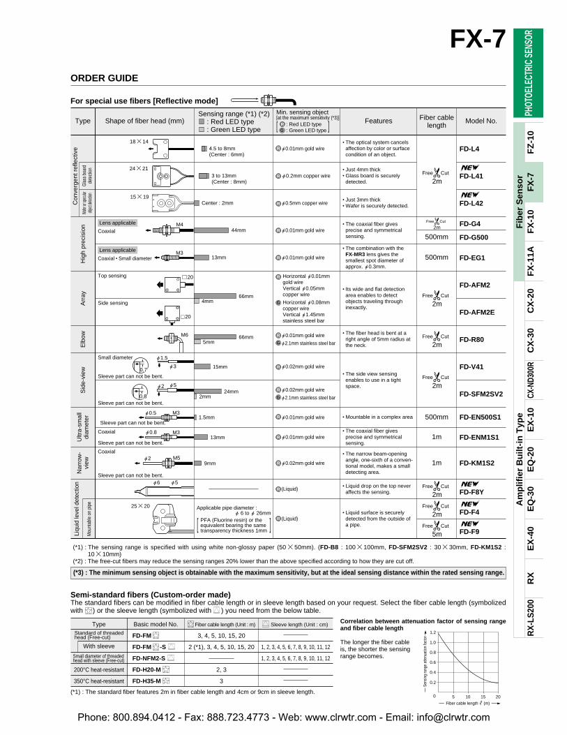
For special use fibers [Reflective mode]
ORDER GUIDE
"0.01mm gold wire
"0.2mm copper wire
"0.01mm gold wire
"2.1mm stainless steel bar
"0.02mm gold wire
"2.1mm stainless steel bar
"0.5mm copper wire
"0.01mm gold wire
"0.01mm gold wire
"0.02mm gold wire
"0.01mm gold wire
"0.01mm gold wire
"0.02mm gold wire
(Liquid)
(Liquid)
Horizontal "0.01mmgold wireVertical "0.05mmcopper wire
Horizontal "0.08mmcopper wireVertical "1.45mmstainless steel bar
• The optical system cancelsaffection by color or surfacecondition of an object.
• Just 4mm thick• Glass board is securelydetected.
• Just 3mm thick• Wafer is securely detected.
• The coaxial fiber givesprecise and symmetricalsensing.
• The combination with the FX-MR3 lens gives thesmallest spot diameter ofapprox. "0.3mm.
• Its wide and flat detectionarea enables to detectobjects traveling throughinexactly.
• The fiber head is bent at aright angle of 5mm radius atthe neck.
• The side view sensingenables to use in a tightspace.
• Mountable in a complex area
• The coaxial fiber givesprecise and symmetricalsensing.
• The narrow beam-openingangle, one-sixth of a conven-tional model, makes a smalldetecting area.
• Liquid drop on the top neveraffects the sensing.
• Liquid surface is securelydetected from the outside ofa pipe.
500mm
500mm
500mm
1m
1m
Sid
e-vi
ewE
lbow
Arr
ayH
igh
prec
isio
nC
onve
rgen
t ref
lect
ive
Ultr
a-sm
all
diam
eter
Nar
row
-vi
ew
Liqu
id le
vel d
etec
tion
Mou
ntab
le o
n pi
peG
lass
boa
rdde
tect
ion
Wafer
or sp
ecula
rob
ject d
etectio
n
FD-L4
FD-L41
FD-L42
FD-EG1
FD-AFM2
FD-AFM2E
FD-R80
FD-V41
FD-SFM2SV2
FD-G4
FD-G500
(*1) : The sensing range is specified with using white non-glossy paper (5050mm). (FD-B8 : 100100mm, FD-SFM2SV2 : 3030mm, FD-KM1S2 :1010mm)
(*2) : The free-cut fibers may reduce the sensing ranges 20% lower than the above specified according to how they are cut off.
R
R
R
R
R
R
R
R
R
R
R
R
G
R
G
R
G
Sleeve part can not be bent.
Sleeve part can not be bent.
Sleeve part can not be bent.
Sleeve part can not be bent.
Sleeve part can not be bent.
Applicable pipe diameter : " 6 to " 26mm
PFA (Fluorine resin) or theequivalent bearing the sametransparency thickness 1mm
Fiber cablelength
Type Shape of fiber head (mm) Features Model No.RG
Coaxial
Top sensing
Side sensing
Small diameter
Coaxial
Coaxial
Coaxial • Small diameter
Lens applicable
Lens applicable
Correlation between attenuation factor of sensing rangeand fiber cable length
The longer the fiber cableis, the shorter the sensingrange becomes.
Sleeve length (Unit : cm)
1, 2, 3, 4, 5, 6, 7, 8, 9, 10, 11, 12
1, 2, 3, 4, 5, 6, 7, 8, 9, 10, 11, 12
TypeStandard of threadedhead (Free-cut)
With sleeve
Small diameter of threadedhead with sleeve (Free-cut)
200°C heat-resistant
350°C heat-resistant
Basic model No.
FD-FM
FD-FM -S
FD-NFM2-S
FD-H20-M
FD-H35-M
Fiber cable length (Unit : m)
3, 4, 5, 10, 15, 20
2 (*1), 3, 4, 5, 10, 15, 20
2, 3
3
Semi-standard fibers (Custom-order made)The standard fibers can be modified in fiber cable length or in sleeve length based on your request. Select the fiber cable length (symbolizedwith ) or the sleeve length (symbolized with ) you need from the below table.
(*1) : The standard fiber features 2m in fiber cable length and 4cm or 9cm in sleeve length.5 10 15 200
0.4
0.8
0.2
0.6
1.2
1.0
Sens
ing
rang
e at
tenu
atio
n fa
ctor
Fiber cable length # (m)
[ ]
(*3) : The minimum sensing object is obtainable with the maximum sensitivity, but at the ideal sensing distance within the rated sensing range.
Phone: 800.894.0412 - Fax: 888.723.4773 - Web: www.clrwtr.com - Email: [email protected]
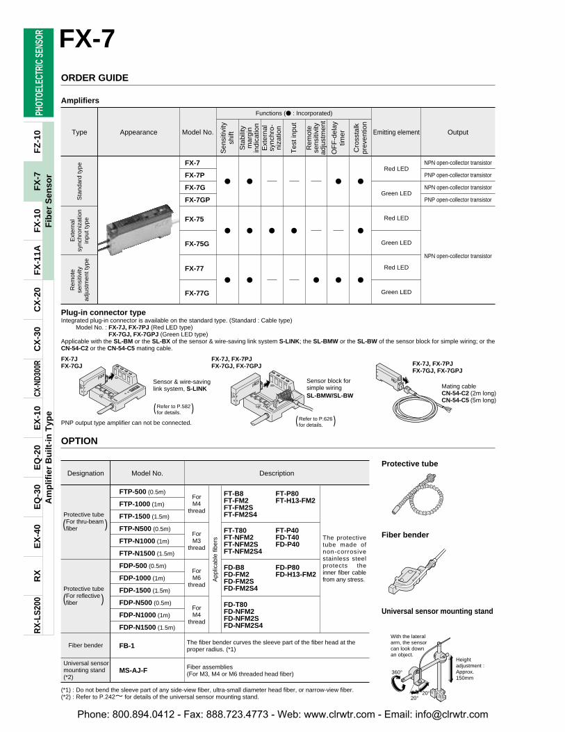
(*1) : Do not bend the sleeve part of any side-view fiber, ultra-small diameter head fiber, or narrow-view fiber.(*2) : Refer to P.242l for details of the universal sensor mounting stand.
With the lateral arm, the sensorcan look down an object.
Heightadjustment : Approx.150mm
360°
20°20°
PHOT
OELE
CTRI
C SE
NSOR
Am
plif
ier
Bu
ilt-i
n T
ype
RX
RX
-LS
200
EX
-40
EQ
-30
EQ
-20
EX
-10
CX-N
D300
RC
X-3
0C
X-2
0F
X-1
1AF
X-1
0F
Z-1
0
App
licab
le fi
bers The protective
tube made ofnon-corrosivestainless steelprotects theinner fiber cablefrom any stress.
The fiber bender curves the sleeve part of the fiber head at theproper radius. (*1)
Fiber assemblies(For M3, M4 or M6 threaded head fiber)
ForM4
thread
ForM3
thread
ForM6
thread
ForM4
thread
FT-B8FT-FM2FT-FM2SFT-FM2S4
FT-P80FT-H13-FM2
FT-T80FT-NFM2FT-NFM2SFT-NFM2S4
FT-P40FD-T40FD-P40
FD-B8FD-FM2FD-FM2SFD-FM2S4
FD-P80FD-H13-FM2
FD-T80FD-NFM2FD-NFM2SFD-NFM2S4
FB-1
MS-AJ-F
FX-7
FX-7P
FX-7G
FX-7GP
FX-75
FX-75G
FX-77
FX-77G
Red LED
Green LED
Red LED
Green LED
Red LED
Green LED
NPN open-collector transistor
PNP open-collector transistor
NPN open-collector transistor
PNP open-collector transistor
NPN open-collector transistor
Type Appearance Model No. Emitting element Output
FX-7
42
Fib
er S
enso
rF
X-7
Amplifiers
ORDER GUIDER
emot
ese
nsiti
vity
adju
stm
ent t
ype
Sta
ndar
d ty
peE
xter
nal
sync
hron
izat
ion
inpu
t typ
e
Functions ( : Incorporated)
Sen
sitiv
itysh
ift
Sta
bilit
ym
argi
nin
dica
tion
Ext
erna
lsy
nchr
o-ni
zatio
n
Tes
t inp
ut
Rem
ote
sens
itivi
tyad
just
men
t
OF
F-d
elay
timer
Cro
ssta
lkpr
even
tion
Plug-in connector typeIntegrated plug-in connector is available on the standard type. (Standard : Cable type)
Model No. : FX-7J, FX-7PJ (Red LED type)FX-7GJ, FX-7GPJ (Green LED type)
Applicable with the SL-BM or the SL-BX of the sensor & wire-saving link system S-LINK; the SL-BMW or the SL-BW of the sensor block for simple wiring; or theCN-54-C2 or the CN-54-C5 mating cable.
Sensor & wire-savinglink system, S-LINK
Refer to P.582for details.
PNP output type amplifier can not be connected.
Sensor block for simple wiringSL-BMW/SL-BW
Mating cableCN-54-C2 (2m long)CN-54-C5 (5m long)
FX-7J, FX-7PJFX-7GJ, FX-7GPJ
FX-7JFX-7GJ FX-7J, FX-7PJ
FX-7GJ, FX-7GPJ
( )Refer to P.626for details.( )
OPTION
Designation Model No. Description
Protective tubeFor thru-beamfiber
FTP-500 (0.5m)
FTP-1000 (1m)
FTP-1500 (1.5m)
FTP-N500 (0.5m)
FTP-N1000 (1m)
FTP-N1500 (1.5m)
FDP-500 (0.5m)
FDP-1000 (1m)
FDP-1500 (1.5m)
FDP-N500 (0.5m)
FDP-N1000 (1m)
FDP-N1500 (1.5m)
Protective tubeFor reflectivefiber
Fiber bender
Universal sensormounting stand(*2)
Protective tube
Fiber bender
Universal sensor mounting stand
( )
( )
Phone: 800.894.0412 - Fax: 888.723.4773 - Web: www.clrwtr.com - Email: [email protected]
PHOT
OELE
CTRI
C SE
NSOR
Am
plif
ier
Bu
ilt-i
n T
ype
RX
RX
-LS
200
EX
-40
EQ
-30
EQ
-20
EX
-10
CX-N
D300
RC
X-3
0C
X-2
0F
X-1
1AF
X-1
0F
Z-1
0
FX-7
43
Fib
er S
enso
rF
X-7
Screw-indepth
Spot diameter
Distance tofocal point
Distance tofocal point
Spot diameter
Screw-indepth
Distance tofocal point
Spotdiameter
Applicable amplifierFiber
FD-EG1 7.50.5mm Approx."0.3mmFD-G4 7.50.5mm Approx."0.5mm
Screw- Distance toin depth focal point Spot diameter
Expansion lens
Super-expansionlens
Side-view lens
Expansion lens forvacuum fiber
Pinpoint spot lens
Zoom lens
Finest spot lens
Zoom lens (Side-view type)
Red LED type Green LED type
Red LED type Green LED type
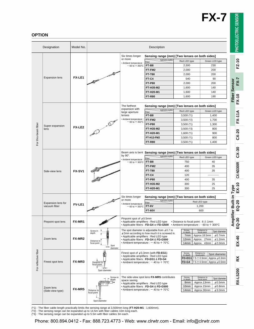
Pinpoint spot of "0.5mm• Applicable amplifiers : Red LED type • Distance to focal point : 61mm• Applicable fibers : FD-G4 or FD-G500 • Ambient temperature :60 to300C
OPTION
Designation Model No. Description
07mm Approx.18.5mm "0.7mm12mm Approx..527mm "1.2mm14mm Approx..543mm "2.0mm
Screw- Distance toin depth focal point Spot diameterThe spot diameter is adjustable from "0.7 to
"2mm according to how much it is screwed in.• Applicable amplifiers : Red LED type• Applicable fibers : FD-G4 & FD-G500• Ambient temperature :40 to70C
08mm Approx.13mm "0.5mm10mm Approx.15mm "0.8mm14mm Approx.30mm "3.0mm
Screw- Distance toin depth focal point Spot diameterThe side-view spot lens FX-MR5 contributes
space saving.• Applicable amplifiers : Red LED type• Applicable fibers : FD-G4 & FD-G500• Ambient temperature :40 to70C
Finest spot of "0.3mm (with FD-EG1)• Applicable amplifiers : Red LED type• Applicable fibers : FD-EG1 & FD-G4• Ambient temperature :40 to70C
(*1) : The fiber cable length practically limits the sensing range at 3,500mm long (FT-H20-M1 : 1,600mm).(*2) : The sensing range can be expanded up to 14.5m with fiber cables 10m long each.(*3) : The sensing range can be expanded up to 5.5m with fiber cables 3m each.
Six times longeror more• Ambient temperature :
60 to350C
The farthestexpansion withlarge aperturelenses• Ambient temperature :
60 to350C
Beam axis is bentby 90.• Ambient temperature :
60 to300C
Six times longeror more• Ambient temperature :
60 to350C
2,500 230
2,000 200
2,000 200
2,540 290
2,000 200
1,600 140
1,600 140
1,600 190
Red LED type Green LED type
FT-B8
FT-FM2
FT-T80
FT-C4
FT-P80
FT-H35-M2
FT-H20-M1
FT-R80
Applicable amplifierFiber
3,500 (*1) 1,400
3,500 (*2) 1,700
3,500 (*1) 1,300
3,500 (*3) 0,800
1,600 (*1) 0,900
3,500 (*1) 0,800
3,500 (*1) 1,400
FT-B8
FT-FM2
FT-P80
FT-H35-M2
FT-H20-M1
FT-H13-FM2
FT-R80
750 40
400 35
400 35
120
400 35
300 25
300 25
FT-B8
FT-FM2
FT-T80
FT-C4
FT-P80
FT-H35-M2
FT-H20-M1
1,200
1,600
Red LED type
FT-6V
FT-60V
For
thru
-bea
m fi
ber
For
ref
lect
ive
fiber
FX-LE1
FX-LE2
FX-SV1
FV-LE1
FX-MR1
FX-MR2
FX-MR3
FX-MR5
Sensing range (mm) [Two lenses on both sides]
Applicable amplifierFiber
Sensing range (mm) [Two lenses on both sides]
Sensing range (mm) [Two lenses on both sides]Applicable amplifier
Fiber
Sensing range (mm) [Two lenses on both sides]
Phone: 800.894.0412 - Fax: 888.723.4773 - Web: www.clrwtr.com - Email: [email protected]
PHOT
OELE
CTRI
C SE
NSOR
Am
plif
ier
Bu
ilt-i
n T
ype
RX
RX
-LS
200
EX
-40
EQ
-30
EQ
-20
EX
-10
CX-N
D300
RC
X-3
0C
X-2
0F
X-1
1AF
X-1
0F
Z-1
0
Acrylic
R25mm or more Flexible : R4mm or more,
Thru-beam of ultra-small diameter : R5mm or more
PolyethyleneReflective of narrow-
view type : Polyurethane,FT-K2 and FT-KV2 :
Polyolefine
SUSBrass
(Nickel plated)Brass
(Nickel plated) Aluminum
SUSFT-KV2 and
Threaded part of FD-EN500S1,
FD-ENM1S1,FT-KM1S2 and
FD-KM1S2 :Brass
Lens of FT-K2 : Glass
Lens of FT-KV2 :Acrylic
ABS : FD-L4,FD-L41,(Lens : Acrylic)Aluminum : FD-L42(Lens : Acrylic) Polyetherimido
Protectivetube :FluorineresinSheath :Polypropylene
R30mm ormore
40 to115°C
R200mmor moreFT-60V :R30mmor more
40 to120°C
R10mm ormore
40 to70°CFD-L42 :
40 to60°C
R25mmor more
FT-K2 andFT-KV2 :R10mmor more
20 to60°CFT-V41,FD-V41,
FT-K2, andFT-KV2 :
40 to60°C
Protective tube :R40mm or moreFiber cable :R15mm or more
40 to125°C(*2)
R10mm ormore
40 to100°C(*2)
40 to70°C(FD-EG1 : 20 to 60°C)
Acrylic
PolyethyleneThru-beam of urtra-small diameter andFlexible except forFT-C4 and FD-P2 :Vinyl chloride
Brass : Threaded part ofstandard, Threaded part ofsmall diameter,High precision, FT-C4,Threaded part ofthru-beam ofultra-small diam-eter, FT-P80,FD-P80, Array,Threaded part of FT-R80
SUS : FT-SFM2,Small fiber head,FT-SNFM2,FD-SNFM2,FT-SFM2L,FT-P40, FT-P2,FD-P40, FD-P2,Sleeve part ofsleeve-attachedfiber
ABS : FT-FM10L(Lens : Acrylic)
Zinc alloy die-casted : Threaded part of FD-R80
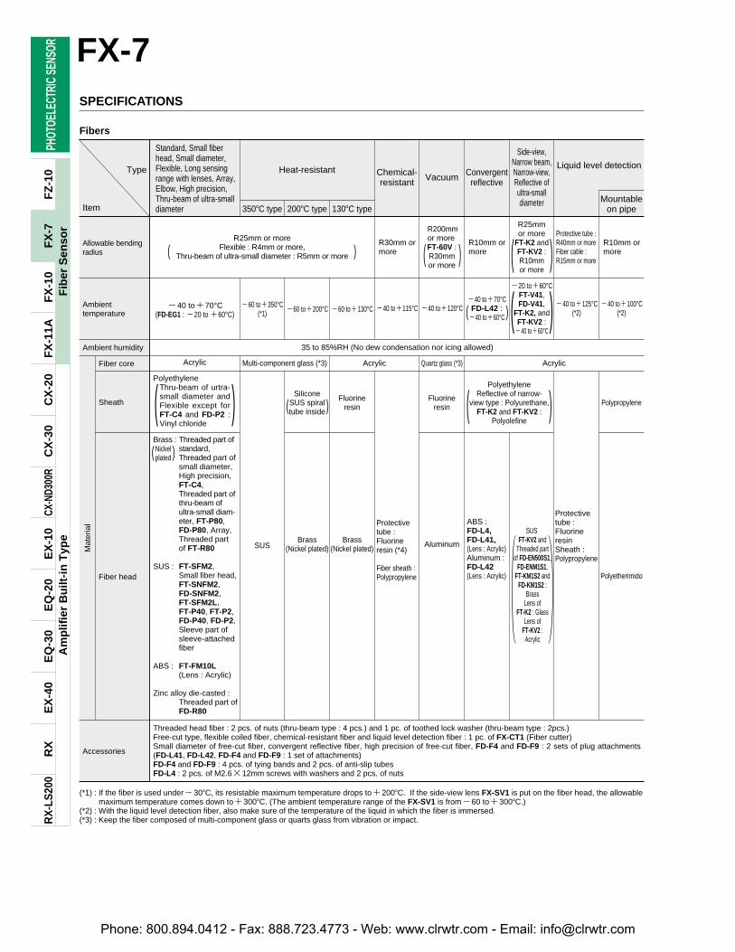
Threaded head fiber : 2 pcs. of nuts (thru-beam type : 4 pcs.) and 1 pc. of toothed lock washer (thru-beam type : 2pcs.)Free-cut type, flexible coiled fiber, chemical-resistant fiber and liquid level detection fiber : 1 pc. of FX-CT1 (Fiber cutter)Small diameter of free-cut fiber, convergent reflective fiber, high precision of free-cut fiber, FD-F4 and FD-F9 : 2 sets of plug attachments(FD-L41, FD-L42, FD-F4 and FD-F9 : 1 set of attachments)FD-F4 and FD-F9 : 4 pcs. of tying bands and 2 pcs. of anti-slip tubesFD-L4 : 2 pcs. of M2.612mm screws with washers and 2 pcs. of nuts
60 to350°C(*1) 60 to200°C 60 to130°C
FX-7
44
Fib
er S
enso
rF
X-7
SPECIFICATIONS
Item
Type
Standard, Small fiberhead, Small diameter,Flexible, Long sensingrange with lenses, Array,Elbow, High precision,Thru-beam of ultra-smalldiameter
Heat-resistant Chemical-resistant Vacuum Convergent
reflective
Liquid level detection
Side-view,Narrow beam, Narrow-view,Reflective ofultra-smalldiameter
Allowable bendingradius
Ambienttemperature
Ambient humidity
Fiber core
Sheath
Fiber head
Accessories
Mat
eria
l
(*1) : If the fiber is used under30C, its resistable maximum temperature drops to200C. If the side-view lens FX-SV1 is put on the fiber head, the allowablemaximum temperature comes down to300C. (The ambient temperature range of the FX-SV1 is from60 to300C.)
(*2) : With the liquid level detection fiber, also make sure of the temperature of the liquid in which the fiber is immersed.(*3) : Keep the fiber composed of multi-component glass or quarts glass from vibration or impact.
350C type 200C type 130C typeMountable
on pipe
Fluorineresin PolypropyleneFluorine
resin
Protectivetube :Fluorineresin (*4)
Fiber sheath :Polypropylene
SiliconeSUS spiraltube inside
AcrylicMulti-component glass (*3) Quartz glass (*3)
(
(
( )
)
)
)(
) ( )
( )(
( ) )(Nickelplated
35 to 85%RH (No dew condensation nor icing allowed)
Fibers
Phone: 800.894.0412 - Fax: 888.723.4773 - Web: www.clrwtr.com - Email: [email protected]
PHOT
OELE
CTRI
C SE
NSOR
Am
plif
ier
Bu
ilt-i
n T
ype
RX
RX
-LS
200
EX
-40
EQ
-30
EQ
-20
EX
-10
CX-N
D300
RC
X-3
0C
X-2
0F
X-1
1AF
X-1
0F
Z-1
0
IncorporatedEither gate or edge trigger is selectable
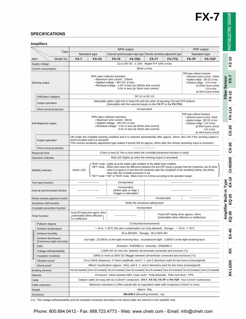
12 to 24V DC 10% Ripple P-P 10% or less
30mA or less
NPN open-collector transistor• Maximum sink current : 100mA• Applied voltage : 30V DC or less• Residual voltage : 1.0V or less (at 100mA sink current)
0.4V or less (at 16mA sink current)
DC-12 or DC-13
Selectable either Light-ON or Dark-ON with the order of pressing ON and OFF buttons (Selectable with the external inputs on the FX-77 or the FX-77G)
Incorporated
NPN open-collector transistor• Maximum sink current : 50mA • Applied voltage : 30V DC or less• Residual voltage : 1.0V or less (at 50mA sink current)
0.4V or less (at 16mA sink current)
ON under the unstable sensing condition and it is restored automatically after approx. 40ms; also ON if the sensing output isshort-circuited until it is removed(The remote sensitivity adjustment type makes it turned ON for approx. 40ms after the remote sensitivity input is received.)
0.5ms or less (0.7ms or less when the crosstalk prevention function is used)
Red LED (lights up when the sensing output is activated)
Green LED “RUN” mode : Lights up at the stable Light condition or the stable Dark condition“SET” mode : Blinks twice when the difference between ON and OFF levels is greater than the hysteresis, but 15 times
when it is equal to or less than the hysteresis after the completion of the sensitivity setting. Also blinks twice after the crosstalk prevention is set
Green LED “SET” moden“SIF” or “RUN” mode : Blinks from 0 to 5 times according to the operation margin
Incorporated
Incorporated
Shifts the sensitivity setting level
Incorporated
Fixed OFF-delay timer approx. 40msswitchable either effective or ineffective
3 (Industrial environment)
10 to 50C (No dew condensation nor icing allowed), Storage : 20 to 70C
35 to 85%RH, Storage : 35 to 85% RH
Sun light : 10,000#x at the light-receiving face, Incandescent light : 3,000#x at the light-receiving face
Emission : EN50081-2, Immunity : EN50082-2
1,000V AC for one min. between all terminals connected and encloure (*1)
20MΩ or more at 250V DC Megger between all terminals connected and enclosure (*1)
10 to 150Hz frequency, 0.75mm amplitude, and X, Y, and Z directions each for two hours (unenergized)
98m/s2 acceleration (approx. 10G), and X, Y, and Z directions each for five times (unenergized)
Red LED (modulated) Green LED (modulated) Red LED (modulated) Green LED (modulated) Red LED (modulated) Green LED (modulated) Red LED (modulated) Green LED (modulated)
Enclosure : Heat-resistant ABS, Case cover : Polycarbonate, Fiber lock lever : PPS
Cabtyre cable 2m long with six 0.15mm2 conductors (FX-7, FX-7G, FX-7P or PX-7GP : four 0.2mm2 conductors)
Maximum extension is 100m overall with an equivalent cable with conductors 0.3mm2 or more
Approx. 65g
MS-DIN-2 (Mounting bracket) : 1pc.
PNP open-collector transistor• Maximum source current : 100mA• Applied voltage : 30V DC or less• Residual voltage : 2.0V or less
(at 100mA source current)1.0V or less
(at 16mA source current)
PNP open-collector transistor• Maximum source current : 50mA• Applied voltage : 30V DC or less• Residual voltage : 2.0V or less
(at 50mA source current)1.0V or less
(at 16mA source current)
FX-7
45
Fib
er S
enso
rF
X-7
SPECIFICATIONS
Type
Item Model No.
NPN output PNP output
Standard type External synchronization input type Remote sensitivity adjustment type Standard type
FX-7 FX-7G FX-75 FX-75G FX-77 FX-77G FX-7P FX-7GP
Supply voltage
Current consumption
Sensing output
Utillization category
Output operation
Short-circuit protection
Self-diagnosis output
Output operation
Short-circuit protection
Response time
Operation indicator
Stability indicator
Test input function
External synchronization function
Remote sensitivity adjustment function
Sensitivity shift function
Crosstalk prevention function
Timer function
Pollution degree
Ambient temperature
Ambient humidity
Ambient illuminance(Extraneous light immunity)
EMC
Voltage withstandability
Insulation resistivity
Vibration-proof
Shock-proof
Emitting element
Material
Cable
Cable extension
Weight
Accessory
Env
ironm
enta
l res
ista
nce
(*1) : The voltage withstandability and the insulation resistivity described in the above table are inherent in the amplifier only.
( )
Fixed OFF-delay timer approx. 40ms (switchable either effective or ineffective)
Amplifiers
Green LED
( )
( )
Phone: 800.894.0412 - Fax: 888.723.4773 - Web: www.clrwtr.com - Email: [email protected]
PHOT
OELE
CTRI
C SE
NSOR
Am
plif
ier
Bu
ilt-i
n T
ype
RX
RX
-LS
200
EX
-40
EQ
-30
EQ
-20
EX
-10
CX-N
D300
RC
X-3
0C
X-2
0F
X-1
1AF
X-1
0F
Z-1
0
ZD2Tr1
Tr2
100mA max.
50mA max.
ZD1
Color code
Users’ circuitInternal circuit
(Brown)V
(Black) Sensing output
(Orange) Self-diagnosis output
(Blue) 0V
LoadLoad
D
5V
5V
Furnish a switch to controleffectiveness of setting switch
(Pink) Remote sensitivity ON input
(Violet) Remote sensitivity OFF input
10kΩ
10kΩ
12 to 24V DC10%
Sen
sor
circ
uit
Brown
Black
Orange
Blue
12 to 24V DC10%
Load
LoadD
ZD2Tr1
Tr2
100mA max.
50mA max.
Color code
LoadZD1
(Brown)V
(Black) Sensing output
(Blue) 0V
Users’ circuitInternal circuit
12 to 24V DC10% (Orange) Self-diagnosis output
Load
Sen
sor
circ
uit
ZD2Tr1
Tr2
100mA max.
50mA max.
ZD1
Color code
Sen
sor
circ
uit
Users’ circuitInternal circuit
(Brown)V
(Pink) External synchronization input
(Violet) Test input
(Black) Sensing output
(Orange) Self-diagnosis output
(Blue) 0V
LoadLoad
D
5V 10kΩ
5V 10kΩ
12 to 24V DC10%
m1
Brown
Black
Orange
Blue
Pink
Violet
12 to 24V DC10%
Load
Load
m1
Brown
Black
Orange
Blue
Pink
Violet
Load
Load
12 to 24V DC10%
D
ZD2
Tr1
Tr2 100mA max.
50mA max.
Color code
Load
Load
ZD1
(Brown)V
(Black) Sensing output
(Orange) Self-diagnosis output
(Blue) 0V
Users’ circuitInternal circuit
12 to 24V DC10%
Sen
sor
circ
uit
Brown
Black
Orange
Blue
12 to 24V DC10%
Load
Load
FX-7
46
Fib
er S
enso
rF
X-7
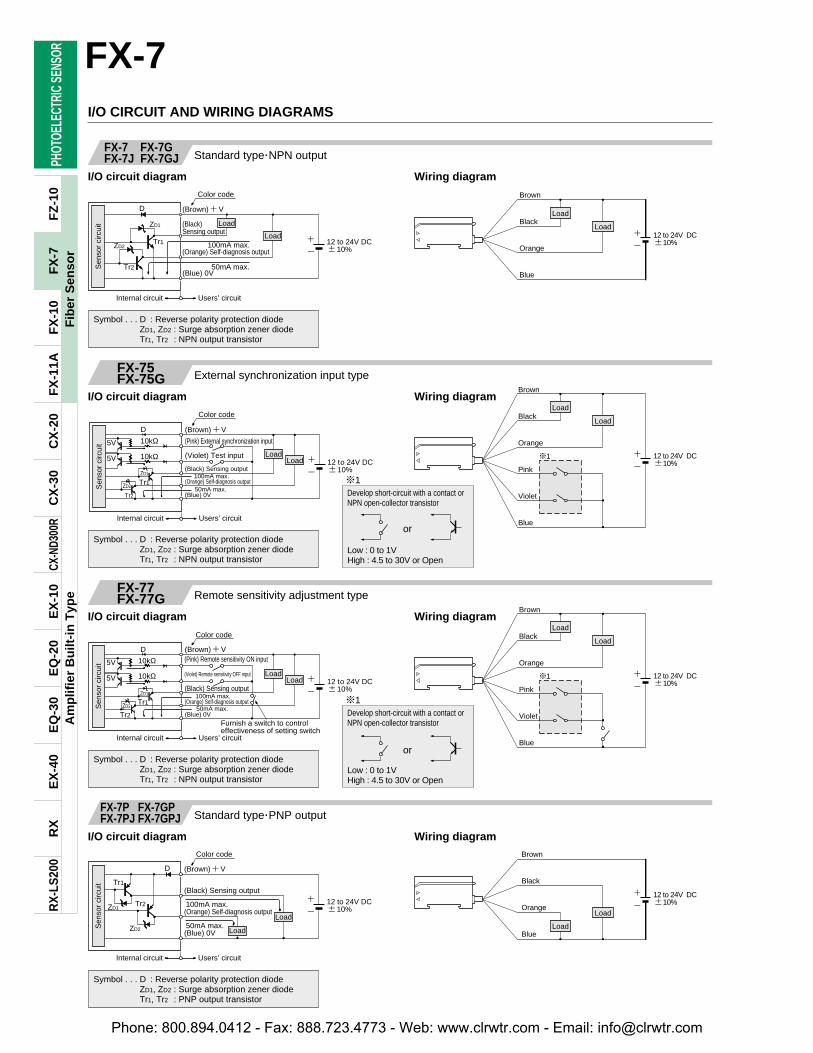
I/O CIRCUIT AND WIRING DIAGRAMS
Symbol . . . D : Reverse polarity protection diodeZD1, ZD2 : Surge absorption zener diodeTr1, Tr2 : NPN output transistor
Symbol . . . D : Reverse polarity protection diodeZD1, ZD2 : Surge absorption zener diodeTr1, Tr2 : NPN output transistor
Standard typeNPN outputFX-7 FX-7GFX-7J FX-7GJ
I/O circuit diagram Wiring diagram
External synchronization input typeFX-75GFX-75G
I/O circuit diagram Wiring diagram
m1
or
Low : 0 to 1VHigh : 4.5 to 30V or Open
Develop short-circuit with a contact orNPN open-collector transistor
Symbol . . . D : Reverse polarity protection diodeZD1, ZD2 : Surge absorption zener diodeTr1, Tr2 : NPN output transistor
Remote sensitivity adjustment typeFX-77GFX-77G
I/O circuit diagram Wiring diagram
m1
or
Low : 0 to 1VHigh : 4.5 to 30V or Open
Develop short-circuit with a contact orNPN open-collector transistor
Symbol . . . D : Reverse polarity protection diodeZD1, ZD2 : Surge absorption zener diodeTr1, Tr2 : PNP output transistor
Standard typePNP outputFX-7P FX-7GPFX-7PJ FX-7GPJ
I/O circuit diagram Wiring diagram
Phone: 800.894.0412 - Fax: 888.723.4773 - Web: www.clrwtr.com - Email: [email protected]
20 10 0 10 200
20
40
Sen
sing
ran
ge L
(m
m)
Left RightCenterOperational point #(mm)
#
Fiberhead
Fiberhead
L
0 100 300 400 5001
10
5
100
200
Exc
ess
gain
50
Green LED type
Red LED type
Setting distance L (mm)0 50 150 200 250
1
10
5
100
100
Exc
ess
gain
50
Setting distance L (mm)
Green LED type
Red LED type
#
Fiberhead
Fiberhead
L
200 100 0 100 2000
200
400
600
800
Set
ting
dist
ance
L (
mm
)
Left RightCenterOperational point #(mm)
200 100 0 100 2000
100
200
300
400
Set
ting
dist
ance
L (
mm
)
Left RightCenterOperational point #(mm)
#
Fiberhead
Fiberhead
L
#
Fiberhead
Fiberhead
L
Set
ting
dist
ance
L (
mm
)
20 10 0 10 20Left RightCenterOperational point #(mm)
40
30
20
10
0
20 10 0 10 200
50
100
Left RightCenterOperational point #(mm)
Set
ting
dist
ance
L (
mm
)
#
Fiberhead
Fiberhead
L
4 2 0 2 40
2
4
6
8
Set
ting
dist
ance
L (
mm
)
Left RightCenterOperational point #(mm)
#
Fiberhead
Fiberhead
L
#
Fiberhead
Fiberhead
40 20 0 20 400
50
100
Left RightCenterOperational point #(mm)
Set
ting
dist
ance
L (
mm
)
L
10 5 0 5 100
2
4
6
8
Set
ting
dist
ance
L (
mm
)
Left RightCenterOperational point #(mm)
#
Fiberhead
Fiberhead
L
100 50 0 50 1000
100
200
300
400
Set
ting
dist
ance
L (
mm
)
Left RightCenterOperational point #(mm)
#
Fiberhead
Fiberhead
L
20 10 0 10 200
10
20
30
40
Set
ting
dist
ance
L (
mm
)
Left RightCenterOperational point #(mm)
#
Fiberhead
Fiberhead
L
#
Fiberhead
Fiberhead
L
100 50 0 50 1000
Set
ting
dist
ance
L (
mm
)
Left RightCenterOperational point #(mm)
0
50
100
10 5 0 5 100
2
4
6
8
Set
ting
dist
ance
L (
mm
)
Left RightCenterOperational point #(mm)
#
Fiberhead
Fiberhead
L
PHOT
OELE
CTRI
C SE
NSOR
Am
plif
ier
Bu
ilt-i
n T
ype
RX
RX
-LS
200
EX
-40
EQ
-30
EQ
-20
EX
-10
CX-N
D300
RC
X-3
0C
X-2
0F
X-1
1AF
X-1
0F
Z-1
0
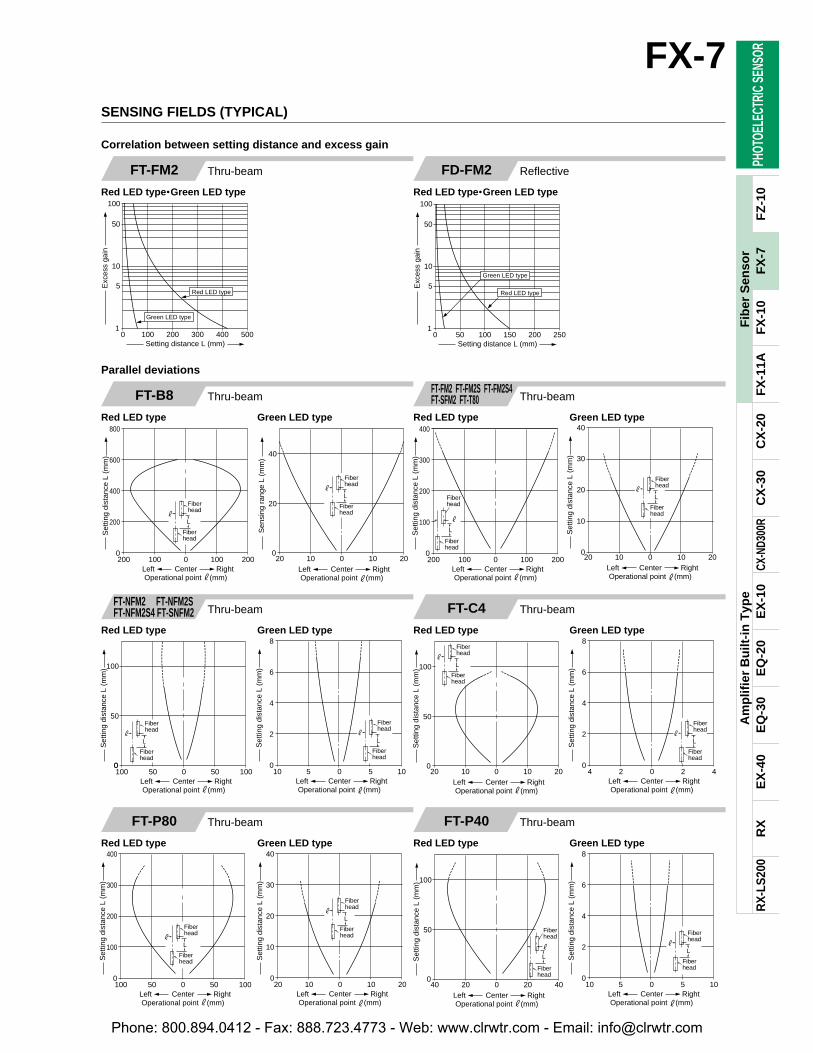
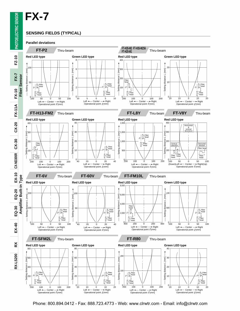
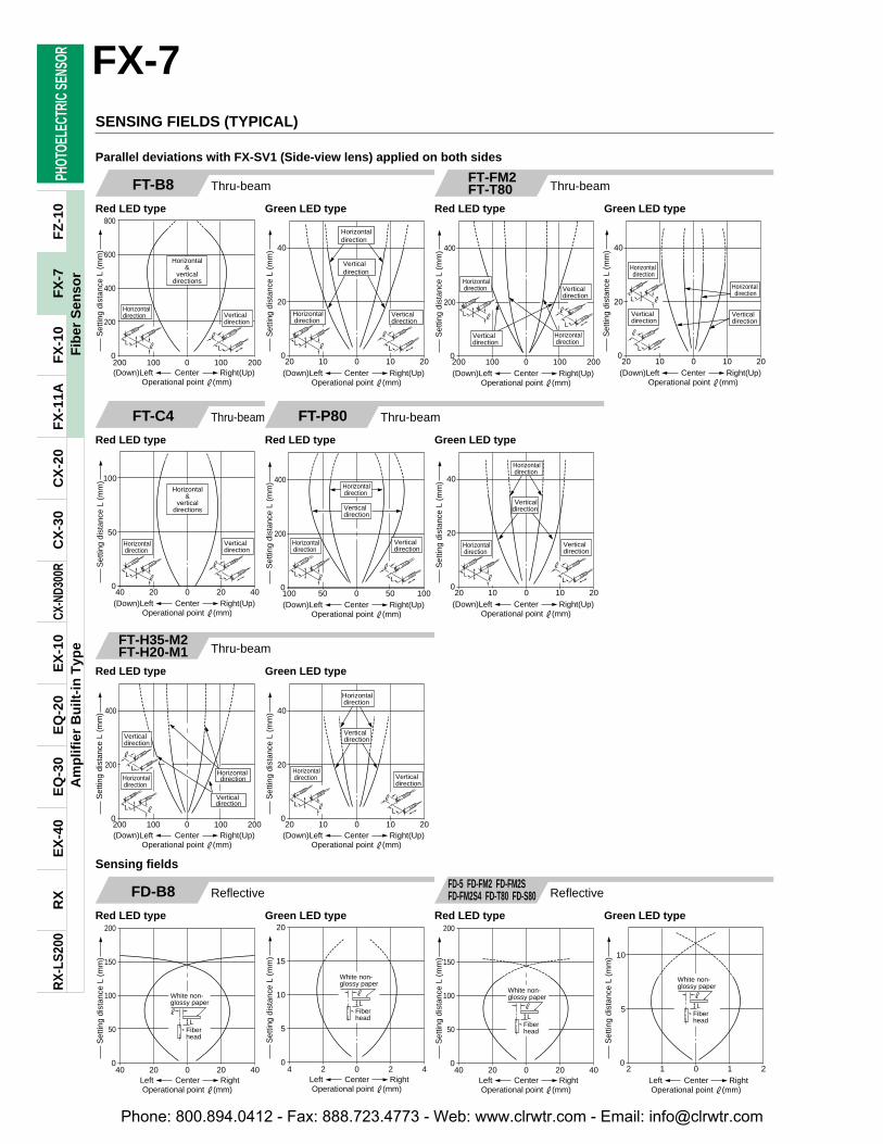
FX-7SENSING FIELDS (TYPICAL)
Thru-beamFT-FM2
Red LED type•Green LED type
ReflectiveFD-FM2
Red LED type•Green LED type
Correlation between setting distance and excess gain
Thru-beam Thru-beamFT-B8
Red LED type Green LED type
FT-FM2 FT-FM2S FT-FM2S4FT-SFM2 FT-T80
Red LED type Green LED type
Thru-beamThru-beam FT-C4
Red LED type Green LED type
Thru-beamFT-P40
Red LED type Green LED type
Thru-beamFT-P80
Red LED type Green LED type
FT-NFM2 FT-NFM2SFT-NFM2S4 FT-SNFM2
Red LED type Green LED type
Parallel deviations
47
Fib
er S
enso
rF
X-7
Phone: 800.894.0412 - Fax: 888.723.4773 - Web: www.clrwtr.com - Email: [email protected]
100 50 0 50 1000
50
100
Left RightCenterOperational point #(mm)
Set
ting
dist
ance
L (
mm
)
#
Fiberhead
Fiberhead
L
10 5 0 5 100
2
4
6
8
Set
ting
dist
ance
L (
mm
)
Left RightCenterOperational point #(mm)
#
Fiberhead
Fiberhead
L
#
Fiberhead
Fiberhead
200 100 0 100 2000
100
200
300
400
Set
ting
dist
ance
L (
mm
)
Left RightCenterOperational point #(mm)
L
0
500
1,000
1,500
2,000
200 100 0 100 200Left RightCenterOperational point #(mm)
#
Fiberhead
Fiberhead
L
Set
ting
dist
ance
L (
mm
)
100 50 0 50 1000
100
200
300
400
Set
ting
dist
ance
L (
mm
)(Down)Left Right(Up)Center
Operational point #(mm)
Horizontal&
verticaldirections
L#
Fiberhead
Fiber head
Horizontaldirection
#
LFiberheadFiber
head
Verticaldirection
100 50 0 50 1000
100
200
Left RightCenterOperational point #(mm)
Set
ting
dist
ance
L (
mm
)
#
Fiberhead
Fiberhead
L
40 20 0 20 400
50
100
Left RightCenterOperational point #(mm)
Set
ting
dist
ance
L (
mm
)
#
Fiberhead
Fiberhead
L
40 20 0 20 400
10
20
30
40
Set
ting
dist
ance
L (
mm
)
Left RightCenterOperational point #(mm)
#
Fiberhead
Fiberhead
L
Fiberhead
Fiberhead
0
2,000
4,000
6,000
8,000
400 200 0 200 400Left RightCenterOperational point #(mm)
Set
ting
dist
ance
L (
mm
)
#
L
100 50 0 50 1000
500
1,000
Left RightCenterOperational point #(mm)
Set
ting
dist
ance
L (
mm
)
#
Fiberhead
Fiberhead
L
200 100 0 100 2000
100
200
Left RightCenterOperational point #(mm)
Set
ting
dist
ance
L (
mm
)
#
Fiberhead
Fiberhead
L
20 10 0 10 200
10
20
30
40
Set
ting
dist
ance
L (
mm
)
Left RightCenterOperational point #(mm)
#
Fiberhead
Fiberhead
L
200 100 0 100 2000
200
400
600
800
Set
ting
dist
ance
L (
mm
)
Left RightCenterOperational point #(mm)
#
Fiberhead
Fiberhead
L
20 10 0 10 200
20
40
60
80
Set
ting
dist
ance
L (
mm
)
Left RightCenterOperational point #(mm)
#
Fiberhead
Fiberhead
L
#
Fiberhead
Fiberhead
200 100 0 100 2000
100
200
300
400
Set
ting
dist
ance
L (
mm
)
Left RightCenterOperational point #(mm)
L
20 10 0 10 200
10
20
Left RightCenterOperational point #(mm)
Set
ting
dist
ance
L (
mm
)
#
Fiberhead
Fiberhead
L
PHOT
OELE
CTRI
C SE
NSOR
Am
plif
ier
Bu
ilt-i
n T
ype
RX
RX
-LS
200
EX
-40
EQ
-30
EQ
-20
EX
-10
CX-N
D300
RC
X-3
0C
X-2
0F
X-1
1AF
X-1
0F
Z-1
0FX-7
48
Fib
er S
enso
rF
X-7
SENSING FIELDS (TYPICAL)
Thru-beam Thru-beamFT-P2
Red LED type Green LED type
Thru-beamFT-H13-FM2
Red LED type Green LED type
Thru-beamFT-L8Y
Red LED type
Thru-beamFT-V8Y
Red LED type
Thru-beamFT-6V
Red LED type
Thru-beamFT-60V
Red LED type
Thru-beamFT-FM10L
Red LED type Green LED type
Thru-beamFT-R80
Red LED type Green LED type
Thru-beamFT-SFM2L
Red LED type Green LED type
FT-H35-M2 FT-H35-M2S6FT-H20-M1
Red LED type Green LED type
Parallel deviations
Phone: 800.894.0412 - Fax: 888.723.4773 - Web: www.clrwtr.com - Email: [email protected]
L#
L
#
FiberheadFiber
head Fiberhead
Fiberhead
Horizontaldirection
Verticaldirection
Horizontal&
verticaldirections
100
50
0100 50 100500
Set
ting
dist
ance
L (
mm
)
(Down)Left Right(Up)CenterOperational point #(mm)
L#
L
#
FiberheadFiber
head Fiberhead
Fiber head
Horizontaldirection
Verticaldirection
Horizontal&
verticaldirections
40
20
040 20 40200
Set
ting
dist
ance
L (
mm
)
(Down)Left Right(Up)CenterOperational point #(mm)
4 2 0 2 40
2
4
6
8
Set
ting
dist
ance
L (
mm
)
Left RightCenterOperational point #(mm)
L#
Fiberhead
Fiberhead
20
10
020 10 20100
Set
ting
dist
ance
L (
mm
)
Left RightCenterOperational point #(mm)
L#
Fiberhead
Fiberhead
10 5 0 5 100
100
200
300
400
Set
ting
dist
ance
L (
mm
)
(Down) Left Right (Up)CenterOperational point #(mm)
Verticaldirection
Horizontaldirection
L#
Fiberhead
Fiberhead
Fiber head
L
#
Fiberhead
Horizontaldirection
Verticaldirection
L#
Fiberhead
Fiberhead
100
50
010 5 1050
Set
ting
dist
ance
L (
mm
)
Left RightCenterOperational point #(mm)
Verticaldirection
Horizontaldirection
200 100 0 100 2000
100
200
Set
ting
dist
ance
L (
mm
)
(Down)Left Right(Up)CenterOperational point #(mm)
Horizontaldirection
Horizontaldirection
Verticaldirection
Verticaldirection
20 10 0 10 200
10
20
Set
ting
dist
ance
L (
mm
)
(Down)Left Right(Up)CenterOperational point #(mm)
Verticaldirection
Horizontaldirection
200 100 0 100 2000
100
200
Set
ting
dist
ance
L (
mm
)
(Down)Left Right(Up)CenterOperational point #(mm)
Horizontaldirection
Verticaldirection
Horizontaldirection
Verticaldirection
20 10 0 10 200
10
20
Set
ting
dist
ance
L (
mm
)
(Down)Left Right(Up)CenterOperational point #(mm)
L#
L
#
FiberheadFiber
head Fiberhead
Fiber head
Horizontaldirection
Verticaldirection
Horizontal&
verticaldirections
100
50
0100 50 100500
Set
ting
dist
ance
L (
mm
)
(Down)Left Right(Up)CenterOperational point #(mm)
Horizontaldirection
Verticaldirection
Horizontal&
verticaldirections
L
#
FiberheadFiber
head
10 5 0 5 100
5
10
15
20
Set
ting
dist
ance
L (
mm
)
(Down)Left Right(Up)CenterOperational point #(mm)
L#
Fiberhead
Fiber head
20 10 0 10 200
200
400
600
800
Set
ting
dist
ance
L (
mm
)
Left RightCenterOperational point #(mm)
L#
Fiberhead
Fiberhead
2 1 0 1 20
20
40
Left RightCenterOperational point #(mm)
Set
ting
dist
ance
L (
mm
)
L#
Fiberhead
Fiberhead
PHOT
OELE
CTRI
C SE
NSOR
Am
plif
ier
Bu
ilt-i
n T
ype
RX
RX
-LS
200
EX
-40
EQ
-30
EQ
-20
EX
-10
CX-N
D300
RC
X-3
0C
X-2
0F
X-1
1AF
X-1
0F
Z-1
0
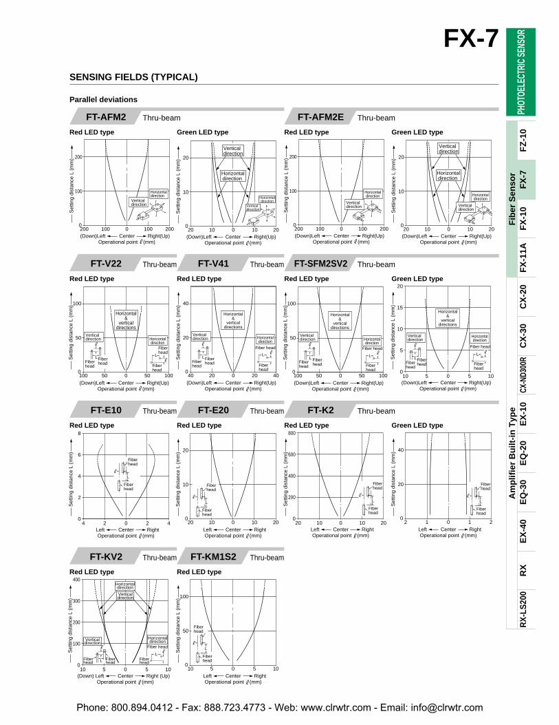
FX-7SENSING FIELDS (TYPICAL)
Thru-beamFT-V22
Red LED type
Thru-beamFT-V41
Red LED type
Thru-beamFT-E10
Red LED type
Thru-beamFT-E20
Red LED type
Thru-beamFT-KV2
Red LED type
Thru-beamFT-KM1S2
Red LED type
Thru-beamFT-AFM2
Red LED type Green LED type
Thru-beamFT-AFM2E
Red LED type Green LED type
Thru-beamFT-SFM2SV2
Red LED type Green LED type
Thru-beamFT-K2
Red LED type Green LED type
Parallel deviations
49
Fib
er S
enso
rF
X-7
Phone: 800.894.0412 - Fax: 888.723.4773 - Web: www.clrwtr.com - Email: [email protected]
L#
Lens top part
Lens top part
0
1,000
2,000
3,000
4,000
200 100 0 100 200Left RightCenterOperational point #(mm)
Set
ting
dist
ance
L (
mm
)
L#
Lenstoppart
Lenstoppart
200
100
040 20 40200
Set
ting
dist
ance
L (
mm
)
Left RightCenterOperational point #(mm)
L#
Lens top part
Lens top part
40 20 0 20 400
200
400
600
800
Set
ting
dist
ance
L (
mm
)
Left RightCenterOperational point #(mm)
L#
Lenstoppart
Lenstoppart
100
50
010 5 1050
Set
ting
dist
ance
L (
mm
)
Left RightCenterOperational point #(mm)
L#
Lenstoppart
Lenstoppart
2,000
1,000
0200 100 2001000
Set
ting
dist
ance
L (
mm
)
Left RightCenterOperational point #(mm)
Lenstoppart
L
Lenstoppart
#
200
100
040 20 40200
Set
ting
dist
ance
L (
mm
)Left RightCenterOperational point #(mm)
L#
Lens top part
Lens top part
2,000
1,000
0400 200 4002000
Set
ting
dist
ance
L (
mm
)
Left RightCenterOperational point #(mm)
Lenstoppart
L#
Lenstoppart
200
100
040 20 40200
Set
ting
dist
ance
L (
mm
)
Left RightCenterOperational point #(mm)
L
Lenstoppart
Lens toppart
0
500
1,000
1,500
2,000
200 100 0 100 200Left RightCenterOperational point #(mm)
Set
ting
dist
ance
L (
mm
)
#
L#
Lenstoppart
Lenstoppart
200
100
040 20 40200
Set
ting
dist
ance
L (
mm
)
Left RightCenterOperational point #(mm)
L#
Lenstoppart
Lenstoppart
2,000
1,000
0200 100 2001000
Set
ting
dist
ance
L (
mm
)
Left RightCenterOperational point #(mm)
L#
Lenstoppart
Lenstoppart
200
100
040 20 40200
Set
ting
dist
ance
L (
mm
)
Left RightCenterOperational point #(mm)
Lenstop part
L
#
Lenstop part
0
1,000
2,000
3,000
4,000
400 200 0 200 400Left RightCenterOperational point #(mm)
Set
ting
dist
ance
L (
mm
)
Lenstop part
L
#
Lenstop part
0
500
1,000
1,500
2,000
200 100 0 100 200Left RightCenterOperational point #(mm)
Set
ting
dist
ance
L (
mm
)
Lenstop part
L
#
Lenstop part
0
1,000
2,000
3,000
4,000
200 100 0 100 200Left RightCenterOperational point #(mm)
Set
ting
dist
ance
L (
mm
)
Lenstop part
L
#
Lenstop part
0
500
1,000
1,500
2,000
100 50 0 50 100Left RightCenterOperational point #(mm)
Set
ting
dist
ance
L (
mm
)
PHOT
OELE
CTRI
C SE
NSOR
Am
plif
ier
Bu
ilt-i
n T
ype
RX
RX
-LS
200
EX
-40
EQ
-30
EQ
-20
EX
-10
CX-N
D300
RC
X-3
0C
X-2
0F
X-1
1AF
X-1
0F
Z-1
0
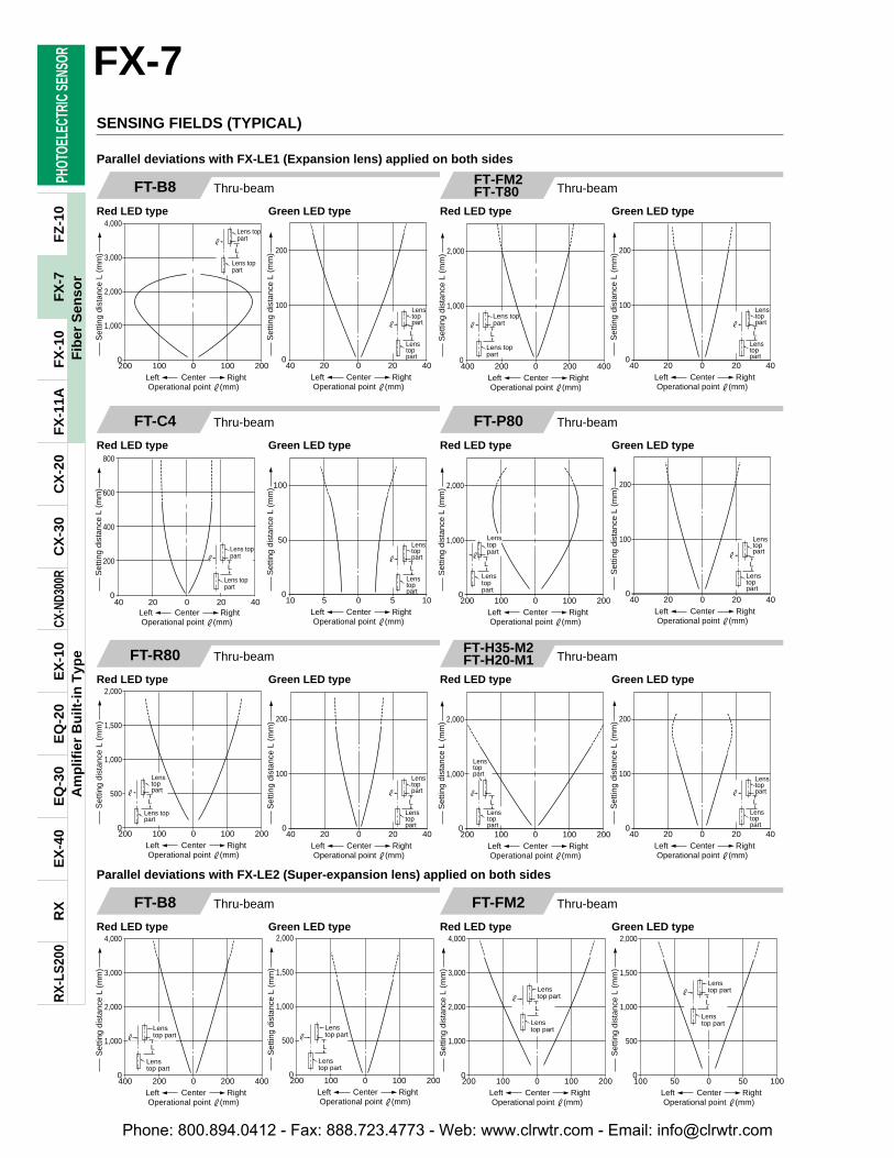
SENSING FIELDS (TYPICAL)
FX-7
50
Fib
er S
enso
rF
X-7
Thru-beamFT-B8
Red LED type Green LED type
Thru-beamFT-C4
Red LED type Green LED type
Thru-beamFT-P80
Red LED type Green LED type
Thru-beamFT-FM2FT-T80
Red LED type Green LED type
Thru-beamFT-R80
Red LED type Green LED type
Thru-beamFT-H35-M2FT-H20-M1
Red LED type Green LED type
Parallel deviations with FX-LE1 (Expansion lens) applied on both sides
Thru-beamFT-B8
Red LED type Green LED type
Thru-beamFT-FM2
Red LED type Green LED type
Parallel deviations with FX-LE2 (Super-expansion lens) applied on both sides
Phone: 800.894.0412 - Fax: 888.723.4773 - Web: www.clrwtr.com - Email: [email protected]
Lenstop part
L
#
Lenstop part
0
1,000
2,000
3,000
4,000
200 100 0 100 200Left RightCenterOperational point #(mm)
Set
ting
dist
ance
L (
mm
)
Lenstop part
L
#
Lenstop part
0
500
1,000
1,500
2,000
100 50 0 50 100Left RightCenterOperational point #(mm)
Set
ting
dist
ance
L (
mm
)
Lenstop part
L
#
Lenstop part
0
1,000
2,000
3,000
4,000
200 100 0 100 200Left RightCenterOperational point #(mm)
Set
ting
dist
ance
L (
mm
)
Lenstop part
L
#
Lenstop part
1,000
500
0100 50 100500
Set
ting
dist
ance
L (
mm
)
Left RightCenterOperational point #(mm)
Lenstop part
L
#
Lenstop part
0
1,000
2,000
3,000
4,000
200 100 0 100 200Left RightCenterOperational point #(mm)
Set
ting
dist
ance
L (
mm
)
Lenstop part
L
#
Lenstop part
1,000
500
0100 50 100500
Set
ting
dist
ance
L (
mm
)
Left RightCenterOperational point #(mm)
Lenstop part
L
#
Lenstop part
0
1,000
2,000
3,000
4,000
200 100 0 100 200Left RightCenterOperational point #(mm)
Set
ting
dist
ance
L (
mm
)
Lenstop part
L
#
Lenstop part
0
500
1,000
1,500
2,000
100 50 0 50 100Left RightCenterOperational point #(mm)
Set
ting
dist
ance
L (
mm
)
Lenstop part
L
#
Lenstop part
0
1,000
2,000
3,000
4,000
400 200 0 200 400Left RightCenterOperational point #(mm)
Set
ting
dist
ance
L (
mm
)
Lenstop part
L
#
Lenstop part
1,000
500
0100 50 100500
Set
ting
dist
ance
L (
mm
)
Left RightCenterOperational point #(mm)
L#
Lens top part
Lens top part
400 200 0 200 4000
5
10
15
20
Set
ting
dist
ance
L (
m)
Left RightCenterOperational point #(mm)
L#
Lenstoppart
Lenstoppart
400 200 0 200 4000
2
4
6
8
Set
ting
dist
ance
L (
m)
Left RightCenterOperational point #(mm)
L#
Lenstoppart
Lenstoppart
1,000
500
0100 50 100500
Left RightCenterOperational point #(mm)
Set
ting
dist
ance
L (
mm
)
L
#
Lens top part
Lens top part
100 50 0 50 1000
200
400
600
800
Set
ting
dist
ance
L (
mm
)
Left RightCenterOperational point #(mm)
PHOT
OELE
CTRI
C SE
NSOR
Am
plif
ier
Bu
ilt-i
n T
ype
RX
RX
-LS
200
EX
-40
EQ
-30
EQ
-20
EX
-10
CX-N
D300
RC
X-3
0C
X-2
0F
X-1
1AF
X-1
0F
Z-1
0
FX-7
51
Fib
er S
enso
rF
X-7
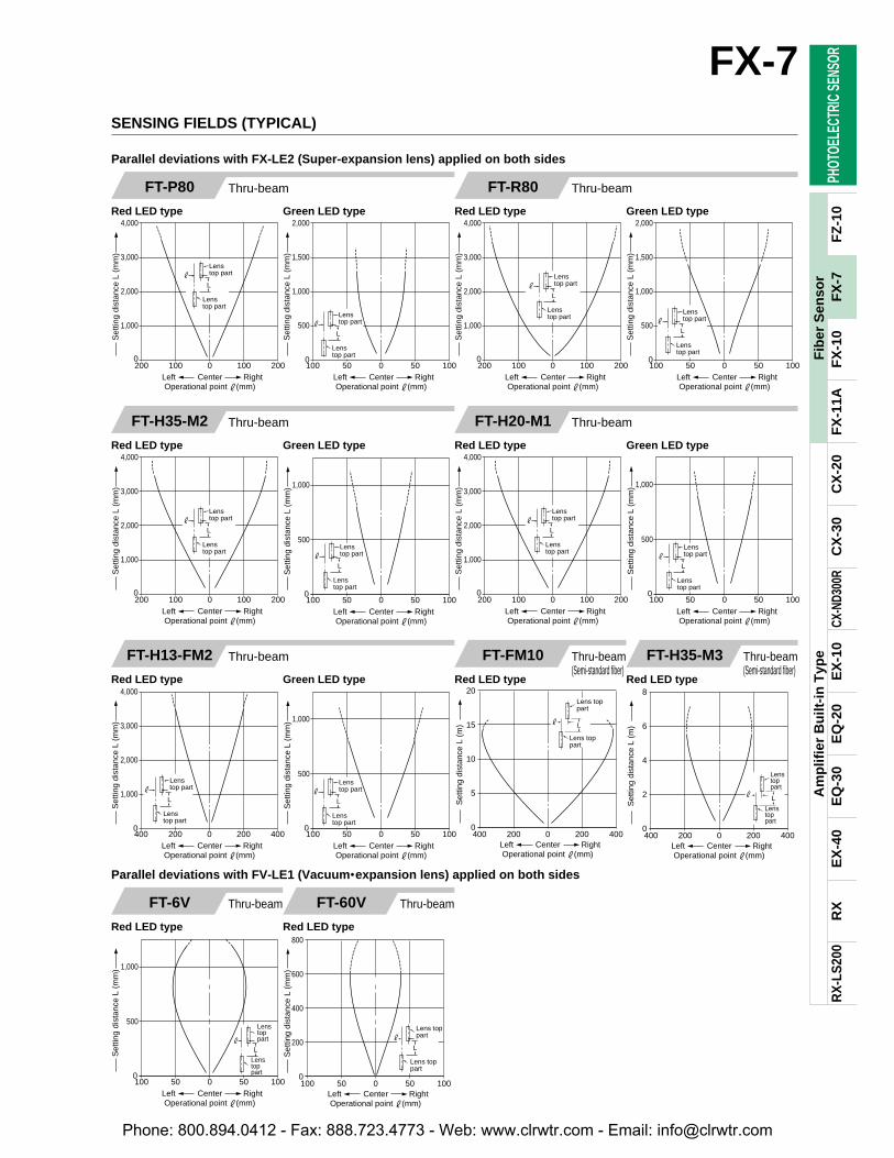
SENSING FIELDS (TYPICAL)
Thru-beamFT-P80
Red LED type Green LED type
Thru-beamFT-H35-M2
Red LED type Green LED type
Thru-beamFT-H20-M1
Red LED type Green LED type
Thru-beamFT-R80
Red LED type Green LED type
Thru-beamFT-H13-FM2
Red LED type Green LED type
Thru-beam(Semi-standard fiber)
FT-FM10
Red LED type
Thru-beam(Semi-standard fiber)
FT-H35-M3
Red LED type
Thru-beamFT-6V
Red LED type
Thru-beamFT-60V
Red LED type
Parallel deviations with FX-LE2 (Super-expansion lens) applied on both sides
Parallel deviations with FV-LE1 (Vacuum•expansion lens) applied on both sides
Phone: 800.894.0412 - Fax: 888.723.4773 - Web: www.clrwtr.com - Email: [email protected]
Horizontal&
verticaldirections
Verticaldirection
Horizontaldirection
200 100 0 100 2000
200
400
600
800
Set
ting
dist
ance
L (
mm
)
(Down)Left Right(Up)CenterOperational point #(mm)
#L#
L
Horizontaldirection
Verticaldirection
40
20
020 10 20100
Set
ting
dist
ance
L (
mm
)
(Down)Left Right(Up)CenterOperational point #(mm)
Verticaldirection
Horizontaldirection
#L#
L
Horizontal&
verticaldirections
Verticaldirection
Horizontaldirection
100
50
040 20 40200
Set
ting
dist
ance
L (
mm
)
(Down)Left Right(Up)CenterOperational point #(mm)
#L
#
L
Horizontaldirection
Verticaldirection
Horizontaldirection
Verticaldirection
400
200
0100 50 100500
Set
ting
dist
ance
L (
mm
)
(Down)Left Right(Up)CenterOperational point #(mm)
#L#
L
Verticaldirection
Horizontaldirection
Verticaldirection
Horizontaldirection
40
20
020 10 20100
Set
ting
dist
ance
L (
mm
)
(Down)Left Right(Up)CenterOperational point #(mm)
#L
#
L
Horizontaldirection
Verticaldirection
Horizontaldirection
Verticaldirection
400
200
0200 100 2001000
Set
ting
dist
ance
L (
mm
)
(Down)Left Right(Up)CenterOperational point #(mm)
#L#
L
40
20
020 10 20100
Set
ting
dist
ance
L (
mm
)
Verticaldirection
Horizontaldirection
(Down)Left Right(Up)CenterOperational point #(mm)
Horizontaldirection
Verticaldirection
#L
#
L
Verticaldirection
Horizontaldirection
Verticaldirection
200 100 0 100 2000
200
400
(Down)Left Right(Up)CenterOperational point #(mm)
Set
ting
dist
ance
L (
mm
)
#L
#
LHorizontaldirection
Horizontaldirection
Verticaldirection
Horizontaldirection Vertical
direction
20 10 0 10 200
20
40
Set
ting
dist
ance
L (
mm
)
(Down)Left Right(Up)CenterOperational point #(mm)
#L#
L
40 20 0 20 400
50
100
150
200
Set
ting
dist
ance
L (
mm
)
Left RightCenterOperational point #(mm)
#L
White non-glossy paper
Fiberhead
#
4 2 0 2 40
5
10
15
20
Set
ting
dist
ance
L (
mm
)
Left RightCenterOperational point #(mm)
L
#
White non-glossy paper
Fiberhead
40 20 0 20 400
50
100
150
200
Set
ting
dist
ance
L (
mm
)
Left RightCenterOperational point #(mm)
L
#
White non-glossy paper
Fiberhead
2 1 0 1 20
5
10
Left RightCenterOperational point #(mm)
Set
ting
dist
ance
L (
mm
)
L
#
White non-glossy paper
Fiberhead
PHOT
OELE
CTRI
C SE
NSOR
Am
plif
ier
Bu
ilt-i
n T
ype
RX
RX
-LS
200
EX
-40
EQ
-30
EQ
-20
EX
-10
CX-N
D300
RC
X-3
0C
X-2
0F
X-1
1AF
X-1
0F
Z-1
0FX-7
52
Fib
er S
enso
rF
X-7
SENSING FIELDS (TYPICAL)
Thru-beamFT-B8
Red LED type Green LED type
Thru-beamFT-C4
Red LED type
Thru-beamFT-P80
Red LED type Green LED type
Thru-beamFT-FM2FT-T80
Red LED type Green LED type
Thru-beamFT-H35-M2FT-H20-M1
Red LED type Green LED type
Parallel deviations with FX-SV1 (Side-view lens) applied on both sides
Reflective ReflectiveFD-B8
Red LED type Green LED type
FD-5 FD-FM2 FD-FM2SFD-FM2S4 FD-T80 FD-S80
Red LED type Green LED type
Sensing fields
Phone: 800.894.0412 - Fax: 888.723.4773 - Web: www.clrwtr.com - Email: [email protected]
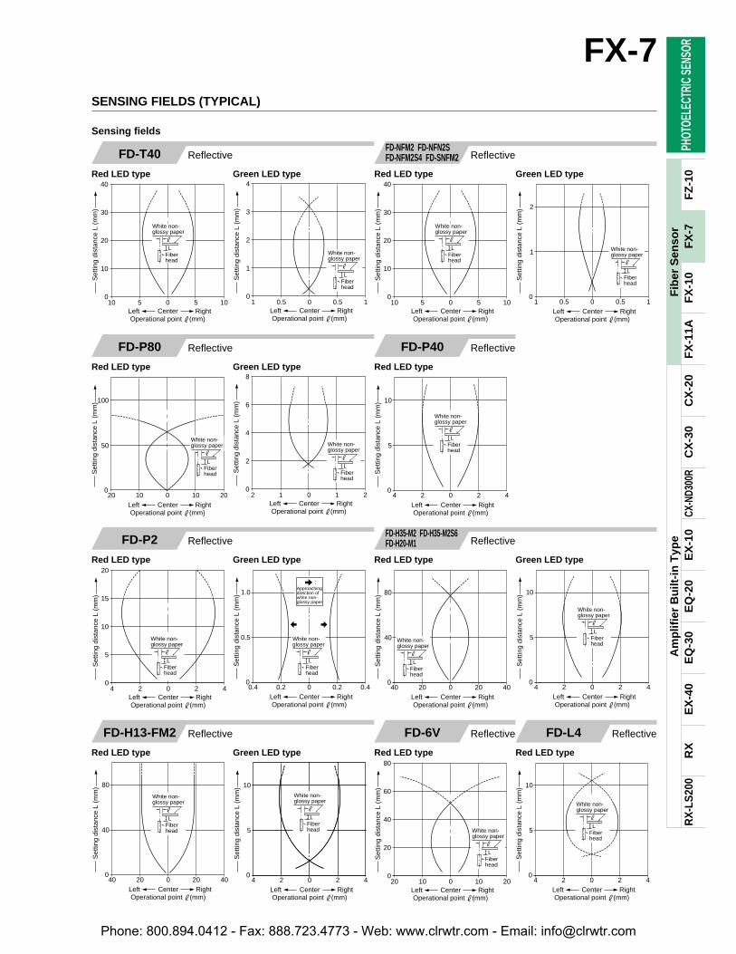
10 5 0 5 100
10
20
30
40
Set
ting
dist
ance
L (
mm
)
Left RightCenterOperational point #(mm)
L
#
White non-glossy paper
Fiberhead
1 0.5 0 0.5 10
1
2
3
4
Set
ting
dist
ance
L (
mm
)
Left RightCenterOperational point #(mm)
L
#
White non-glossy paper
Fiberhead
20 10 0 10 200
20
40
60
80
Set
ting
dist
ance
L (
mm
)
Left RightCenterOperational point #(mm)
L
#
White non-glossy paper
Fiberhead
10
5
04 2 420
Set
ting
dist
ance
L (
mm
)
Left RightCenterOperational point #(mm)
L
#
White non-glossy paper
Fiberhead
L
#
White non-glossy paper
Fiberhead
4 2 0 2 40
5
10
15
20
Set
ting
dist
ance
L (
mm
)
Left RightCenterOperational point #(mm)
Approachingdirection of 1.0
0.5
00.4 0.2 0.40.20
Set
ting
dist
ance
L (
mm
)
Left RightCenterOperational point #(mm)
white non-glossy paper
L
#
White non-glossy paper
Fiberhead
:
10 5 0 5 100
10
20
30
40
Set
ting
dist
ance
L (
mm
)
Left RightCenterOperational point #(mm)
L
#
White non-glossy paper
Fiberhead
1 0.5 0 0.5 10
1
2
Left RightCenterOperational point #(mm)
Set
ting
dist
ance
L (
mm
)
L
#
White non-glossy paper
Fiberhead
80
40
040 20 40200
Set
ting
dist
ance
L (
mm
)
Left RightCenterOperational point #(mm)
L
#
White non-glossy paper
Fiberhead
10
5
04 2 420
Set
ting
dist
ance
L (
mm
)
Left RightCenterOperational point #(mm)
L
#
White non-glossy paper
Fiberhead
4 2 0 2 40
5
10
Left RightCenterOperational point #(mm)
Set
ting
dist
ance
L (
mm
)
L
#
White non-glossy paper
Fiberhead
20 10 0 10 200
50
100
Left RightCenterOperational point #(mm)
Set
ting
dist
ance
L (
mm
)
L
#
White non-glossy paper
Fiberhead
2 1 0 1 20
2
4
6
8
Set
ting
dist
ance
L (
mm
)
Left RightCenterOperational point #(mm)
L
#
White non-glossy paper
Fiberhead
80
40
040 20 40200
Set
ting
dist
ance
L (
mm
)
Left RightCenterOperational point #(mm)
L
#
White non-glossy paper
Fiberhead
10
5
04 2 420
Set
ting
dist
ance
L (
mm
)
Left RightCenterOperational point #(mm)
L
#
White non-glossy paper
Fiberhead
PHOT
OELE
CTRI
C SE
NSOR
Am
plif
ier
Bu
ilt-i
n T
ype
RX
RX
-LS
200
EX
-40
EQ
-30
EQ
-20
EX
-10
CX-N
D300
RC
X-3
0C
X-2
0F
X-1
1AF
X-1
0F
Z-1
0
FX-7
53
Fib
er S
enso
rF
X-7
SENSING FIELDS (TYPICAL)
Reflective ReflectiveFD-T40
Red LED type Green LED type
ReflectiveFD-6V
Red LED type
ReflectiveFD-L4
Red LED type
Reflective ReflectiveFD-P2
Red LED type Green LED type
Sensing fields
FD-NFM2 FD-NFN2SFD-NFM2S4 FD-SNFM2
Red LED type Green LED type
ReflectiveFD-H13-FM2
Red LED type Green LED type
ReflectiveFD-P40
Red LED type
ReflectiveFD-P80
Red LED type Green LED type
FD-H35-M2 FD-H35-M2S6FD-H20-M1
Red LED type Green LED type
Phone: 800.894.0412 - Fax: 888.723.4773 - Web: www.clrwtr.com - Email: [email protected]

20 10 0 10 200
20
40
60
80
Set
ting
dist
ance
L (
mm
)
Left RightCenterOperational point #(mm)
L#
White non-glossy paper
Fiberhead
L#
0.4 0.2 0 0.4 0.20
1
2
3
4
Set
ting
dist
ance
L (
mm
)
Fiberhead
Wafer
Down UpCenterOperational point #(mm)
L#
0.4 0.2 0 0.4 0.20
1
2
3
4
Set
ting
dist
ance
L (
mm
)
Down UpCenterOperational point #(mm)
Fiberhead
Glassboard
Approachingdirection ofglass board
:
L
#
Verticaldirection
Horizontal&
verticaldirections
Horizontaldirection
L
#
White non-glossy paper
White non-glossy paper
Fiberhead Fiber
head
10 5 0 5 100
5
10
15
20
Set
ting
dist
ance
L (
mm
)
CenterOperational point #(mm)
(Down)Left Right(Up)
4 2 0 2 40
5
10
15
20
Set
ting
dist
ance
L (
mm
)
Left RightCenterOperational point #(mm)
L#
White non-glossy paper
Fiberhead
L#
40
20
010 5 1050
Set
ting
dist
ance
L (
mm
)
Left RightCenterOperational point #(mm)
White non-glossy paper
Fiberhead
Horizontaldirection
Horizontaldirection
Verticaldirection
3mm
2525t1.3mmglass board
L##
12mm L
1 0.5 0 0.5 10
5
10
15
20
Set
ting
dist
ance
L (
mm
)
Verticaldirection
(Down)Left Right(Up)CenterOperational point #(mm)
252t1.3mmglass board
2 1 0 1 20
2
4
6
8
Set
ting
dist
ance
L (
mm
)
Left RightCenterOperational point #(mm)
L#
White non-glossy paper
Fiberhead
Fiberhead
Horizontaldirection
L
#
L
#
Verticaldirection
Horizontal&
verticaldirections
10 5 0 5 100
10
20
30
40
Set
ting
dist
ance
L (
mm
)
(Down)Left Right(Up)CenterOperational point #(mm)
Fiberhead
White non-glossy paperWhite non-
glossy paperL
#
L
#
Approachingdirection of white non-
Fiberhead
Verticaldirection
Verticaldirection
Horizontaldirection
Horizontaldirection
Fiberhead
0.4 0.2 0 0.2 0.40
1
2
Sen
sing
ran
ge L
(m
m)
White non-glossy paper
White non-glossy paper
glossy paper
(Down)Left Right(Up)CenterOperational point #(mm)
:
L
#
40
20
020 10 20100
Set
ting
dist
ance
L (
mm
)
Left RightCenterOperational point #(mm)
White non-glossy paper
Fiberhead
L#
4 2 0 2 40
5
10
15
20
Set
ting
dist
ance
L (
mm
)
Left RightCenterOperational point #(mm)
White non-glossy paper
Fiberhead
Horizontal & vertical directions
Verticaldirection
Horizontaldirection
20 10 0 10 200
20
40
60
80
Set
ting
dist
ance
L (
mm
)
White non-glossypaper
(Down)Left Right(Up)CenterOperational point #(mm)
Horizontaldirection
Horizontaldirection
Verticaldirection
4
2
04 2 420
Set
ting
dist
ance
L (
mm
)
White non-glossy paper
(Down)Left Right(Up)CenterOperational point #(mm)
Verticaldirection
1 0.5 0 0.5 10
0.5
1
1.5
2
Set
ting
dist
ance
L (
mm
)
Left RightCenterOperational point #(mm)
L#
White non-glossy paper
Fiberhead
PHOT
OELE
CTRI
C SE
NSOR
Am
plif
ier
Bu
ilt-i
n T
ype
RX
RX
-LS
200
EX
-40
EQ
-30
EQ
-20
EX
-10
CX-N
D300
RC
X-3
0C
X-2
0F
X-1
1AF
X-1
0F
Z-1
0FX-7
54
Fib
er S
enso
rF
X-7
ReflectiveFD-L42
Red LED type (Wafer) Red LED type (Glass board)
ReflectiveFD-EN500S1
Red LED type
Reflective
Reflective
Reflective
FD-V41
Red LED type
FD-ENM1S1
Red LED type
FD-G4
Red LED type
FD-L41
Red LED type
ReflectiveFD-R80
Red LED type Green LED type
Sensing fields
ReflectiveFD-SFM2SV2
Red LED type Green LED type
Reflective
Reflective
FD-G500
Red LED type
ReflectiveFD-EG1
Red LED type
ReflectiveFD-AFM2FD-AFM2E
Red LED type Green LED type
SENSING FIELDS (TYPICAL)
Phone: 800.894.0412 - Fax: 888.723.4773 - Web: www.clrwtr.com - Email: [email protected]
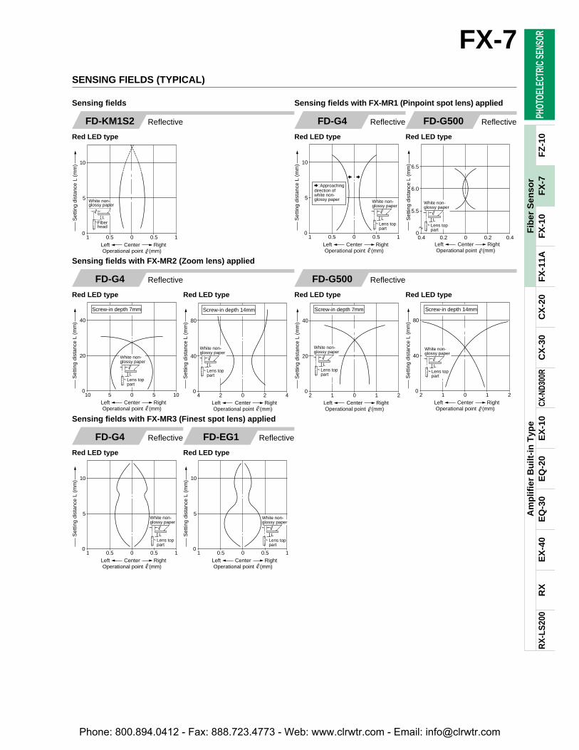
10 5 0 5 100
20
40
Left RightCenterOperational point #(mm)
Set
ting
dist
ance
L (
mm
)
Screw-in depth 7mm
Lens top part
L
#
White non-glossy paper
4 2 0 2 40
40
80
Left RightCenterOperational point #(mm)
Set
ting
dist
ance
L (
mm
)
Lens top part
L
#
White non-glossy paper
Screw-in depth 14mm Screw-in depth 7mm
2 1 0 1 20
20
40
Left RightCenterOperational point #(mm)
Set
ting
dist
ance
L (
mm
)
Lens top part
L
#
White non-glossy paper
Screw-in depth 14mm
2 1 0 1 20
40
80
Left RightCenterOperational point #(mm)
Set
ting
dist
ance
L (
mm
)
Lens top part
L
#
White non-glossy paper
1 0.5 0 0.5 10
5
10
Left RightCenterOperational point #(mm)
Set
ting
dist
ance
L (
mm
)
L#
White non-glossy paper
Fiberhead
1 0.5 0 0.5 10
5
10
Left RightCenterOperational point #(mm)
Set
ting
dist
ance
L (
mm
)
Lens top part
L
#
White non-glossy paper
1 0.5 0 0.5 10
5
10
Left RightCenterOperational point #(mm)
Set
ting
dist
ance
L (
mm
)
Lens top part
L
#
White non-glossy paper
:Approachingdirection ofwhite non-glossy paper
Lens top part
L
#
1 0.5 0 0.5 10
5
10
Left RightCenterOperational point #(mm)
White non-glossy paper
Set
ting
dist
ance
L (
mm
)
0.4 0.2 0 0.2 0.40
5.5
6.0
6.5
Set
ting
dist
ance
L (
mm
)
Left RightCenterOperational point #(mm)
Lens top part
L
#
White non-glossy paper
PHOT
OELE
CTRI
C SE
NSOR
Am
plif
ier
Bu
ilt-i
n T
ype
RX
RX
-LS
200
EX
-40
EQ
-30
EQ
-20
EX
-10
CX-N
D300
RC
X-3
0C
X-2
0F
X-1
1AF
X-1
0F
Z-1
0
FX-7
55
Fib
er S
enso
rF
X-7
ReflectiveFD-G4
Red LED type Red LED type
ReflectiveFD-G500
Red LED type Red LED type
FD-KM1S2
Red LED type
Sensing fields Sensing fields with FX-MR1 (Pinpoint spot lens) applied
Sensing fields with FX-MR2 (Zoom lens) applied
Reflective
FD-G4
Red LED type
Sensing fields with FX-MR3 (Finest spot lens) applied
Reflective FD-EG1
Red LED type
Reflective
FD-G4
Red LED type
Reflective ReflectiveFD-G500
Red LED type
SENSING FIELDS (TYPICAL)
Phone: 800.894.0412 - Fax: 888.723.4773 - Web: www.clrwtr.com - Email: [email protected]
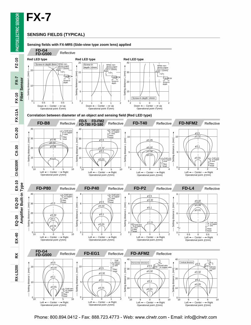
"0.45"0.32
"0.08
"0.01
10 5 0 5 100
10
20
30
40
Set
ting
dist
ance
L (
mm
)
Left RightCenterOperational point #(mm)
L
Gold wire or copper wire
#
Fiberhead
"0.45
"0.32
"0.08
"0.01
L
#
10
5
04 2 420
Set
ting
dist
ance
L (
mm
)
Left RightCenterOperational point #(mm)
Fiberhead
Gold wire or copper wire L
"0.5"0.32
"0.1
"0.01 #
10
5
04 2 420
Set
ting
dist
ance
L (
mm
)Left RightCenterOperational point #(mm)
Fiberhead
Gold wire or copper wire
L
"0.01
"0.1
"0.5
"0.32
# Gold wire or copper wire
10 5 0 5 100
10
20
30
40
Set
ting
dist
ance
L (
mm
)
Left RightCenterOperational point #(mm)
Fiberhead
L
"0.5
"0.32
"0.1
"0.01
# Gold wire or copper wire
2 1 0 1 20
2
4
6
8
Set
ting
dist
ance
L (
mm
)
Left RightCenterOperational point #(mm)
Fiberhead
"0.5
"0.32
"0.1
"0.01
2 1 0 1 20
2
4
6
8
Set
ting
dist
ance
L (
mm
)
Left RightCenterOperational point #(mm)
L#
Fiberhead
Gold wire or copper wire
"0.5
"0.32
"0.1
"0.01
20
10
010 5 1050
Set
ting
dist
ance
L (
mm
)
Left RightCenterOperational point #(mm)
L# Gold wire
or copper wire
Fiberhead
"0.5
"0.32
"0.1
"0.01
10
5
02 1 210
Set
ting
dist
ance
L (
mm
)
Left RightCenterOperational point #(mm)
L
#
Fiberhead
Goldwire or copperwire
Horizontal direction
"0.5
"0.32
"0.1
"0.01
10 5 0 5 100
10
20
30
40
Set
ting
dist
ance
L (
mm
)
Left RightCenterOperational point #(mm)
Gold wire or copper wire
"0.32
"0.1
"0.05
"0.5Vertical direction
10 5 0 5 100
10
20
30
40
Set
ting
dist
ance
L (
mm
)
Left RightCenterOperational point #(mm)
Gold wire or copperwire
L
"0.32
"0.08
"0.01
# Gold wire or copper wire
1 0.5 0 0.5 10
5
6
7
8
Set
ting
dist
ance
L (
mm
)
Left RightCenterOperational point #(mm)
Fiberhead
L
"0.32"0.1
"0.01
# Gold wire or copper wire
10 5 0 5 100
10
20
30
40
Set
ting
dist
ance
L (
mm
)
Left RightCenterOperational point #(mm)
Fiberhead
"0.5
Screw-in depth 8mm
L #
(1515mm)
Screw-indepth
1 0.5 0 0.5 10
10
20
Down UpCenterOperational point #(mm)
White non-glossy paper
Set
ting
dist
ance
L (
mm
)
Screw-indepth 10mm
L #
(1515mm)
Screw-indepth
White non-glossy paper
2 1 0 1 20
5
10
15
20
Set
ting
dist
ance
L (
mm
)
CenterOperational point #(mm)
Down Up
L #
(1515mm)
Screw-indepth
White non-glossy paper
2 1 0 1 20
10
20
30
40
Set
ting
dist
ance
L (
mm
)
CenterOperational point #(mm)
Down Up
Screw-in depth 14mm
PHOT
OELE
CTRI
C SE
NSOR
Am
plif
ier
Bu
ilt-i
n T
ype
RX
RX
-LS
200
EX
-40
EQ
-30
EQ
-20
EX
-10
CX-N
D300
RC
X-3
0C
X-2
0F
X-1
1AF
X-1
0F
Z-1
0FX-7
56
Fib
er S
enso
rF
X-7
FD-B8
Correlation between diameter of an object and sensing field (Red LED type)
Reflective FD-T40 Reflective FD-NFM2 Reflective
FD-P80 Reflective FD-P40 Reflective FD-P2 Reflective
FD-G4FD-G500 Reflective FD-EG1 Reflective FD-AFM2 Reflective
FD-L4 Reflective
FD-5 FD-FM2FD-T80 FD-S80 Reflective
SENSING FIELDS (TYPICAL)
FD-G4FD-G500
Red LED type
Sensing fields with FX-MR5 (Side-view type zoom lens) applied
Reflective
Red LED type Red LED type
Phone: 800.894.0412 - Fax: 888.723.4773 - Web: www.clrwtr.com - Email: [email protected]
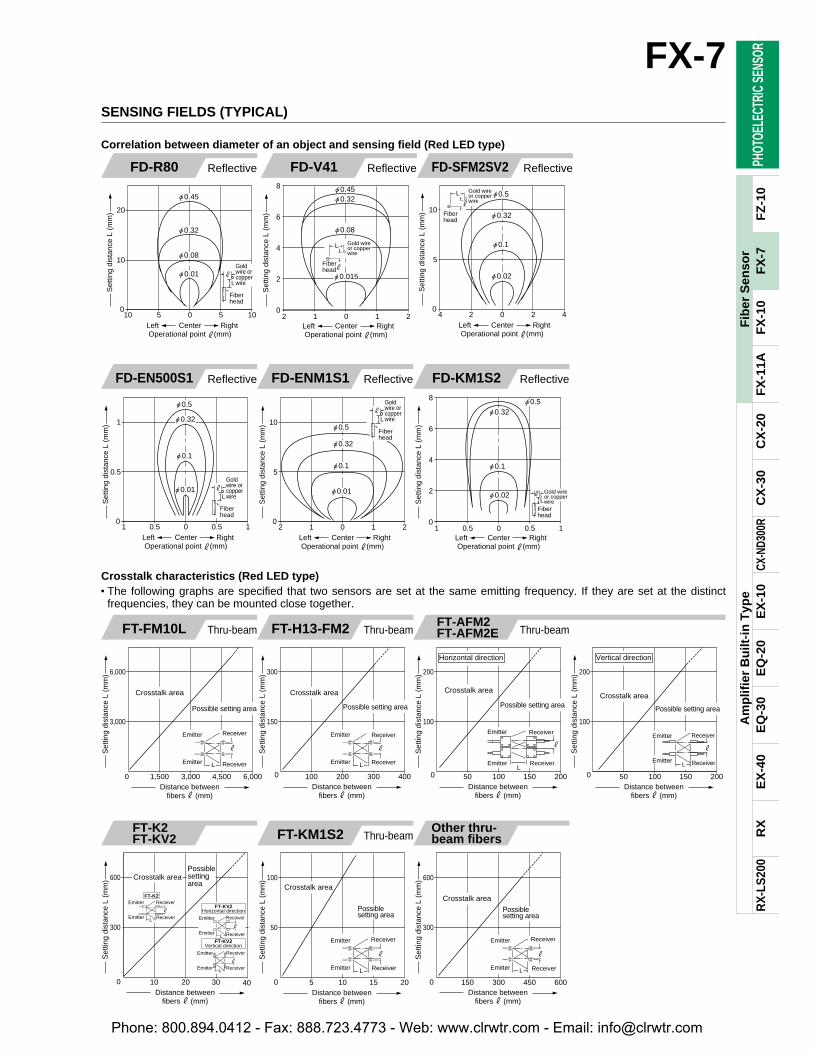
"0.32
"0.1
"0.01
"0.5
1
0.5
01 0.5 10.50
Set
ting
dist
ance
L (
mm
)
Left RightCenterOperational point #(mm)
L
#
Fiberhead
Goldwire or copperwire
"0.5
"0.32
"0.1
"0.01
10
5
02 1 210
Set
ting
dist
ance
L (
mm
)
Left RightCenterOperational point #(mm)
L
#
Fiberhead
Goldwire or copperwire
1 0.5 0 0.5 10
2
4
6
8
Set
ting
dist
ance
L (
mm
)
Left RightCenterOperational point #(mm)
"0.5"0.32
"0.1
"0.02L
# Gold wire or copper wire
Fiberhead
Crosstalk area
Possible setting area
6,000
3,000
0 1,500 6,0004,5003,000
Set
ting
dist
ance
L (
mm
)
LEmitter
ReceiverEmitter
Receiver
#
Distance betweenfibers # (mm)
0
Crosstalk area
Possible setting area
L
300
150
100 400300200
Set
ting
dist
ance
L (
mm
)
ReceiverEmitter
#
Emitter Receiver
Distance betweenfibers # (mm)
L
10 20 30 400
300
600 Crosstalk area
Set
ting
dist
ance
L (
mm
)
ReceiverEmitter L
ReceiverEmitter
#
FT-KV2Horizontal direction
FT-KV2Vertical direction
ReceiverEmitterL
ReceiverEmitter
#
Distance betweenfibers # (mm)
ReceiverEmitter L
ReceiverEmitter
#
FT-K2
Possiblesettingarea
0
Crosstalk area
Possiblesetting area
L Receiver
Receiver
#
100
50
5 201510
Set
ting
dist
ance
L (
mm
)
Emitter
Emitter
Distance betweenfibers # (mm)
0
Crosstalk area
Possiblesetting area
L Receiver
Receiver
#
600
300
150 600450300
Set
ting
dist
ance
L (
mm
)
Emitter
Emitter
Distance betweenfibers # (mm)
0
Possible setting area
Crosstalk area
Emitter
Emitter
Receiver
Receiver
Horizontal direction
#
L
200
100
50 200150100
Set
ting
dist
ance
L (
mm
)
Distance betweenfibers # (mm)
0
Possible setting area
Crosstalk area
ReceiverEmitterL
ReceiverEmitter
Vertical direction
#
200
100
50 200150100
Set
ting
dist
ance
L (
mm
)
Distance betweenfibers # (mm)
"0.45
"0.32
"0.08
"0.01L
#
20
10
010 5 1050
Set
ting
dist
ance
L (
mm
)
Left RightCenterOperational point #(mm)
Fiberhead
Goldwire or copperwire
"0.45"0.32
"0.08
"0.015
Gold wire or copper wire
L
#
2 1 0 1 20
2
4
6
8
Set
ting
dist
ance
L (
mm
)
Left RightCenterOperational point #(mm)
Fiberhead
"0.5
"0.32
"0.1
"0.02
Gold wire or copper wire
L
#10
5
04 2 420
Set
ting
dist
ance
L (
mm
)
Left RightCenterOperational point #(mm)
Fiberhead
PHOT
OELE
CTRI
C SE
NSOR
Am
plif
ier
Bu
ilt-i
n T
ype
RX
RX
-LS
200
EX
-40
EQ
-30
EQ
-20
EX
-10
CX-N
D300
RC
X-3
0C
X-2
0F
X-1
1AF
X-1
0F
Z-1
0
FX-7
57
Fib
er S
enso
rF
X-7
FD-EN500S1
Correlation between diameter of an object and sensing field (Red LED type)
Reflective FD-ENM1S1 Reflective FD-KM1S2 Reflective
FT-FM10L
Crosstalk characteristics (Red LED type)• The following graphs are specified that two sensors are set at the same emitting frequency. If they are set at the distinct
frequencies, they can be mounted close together.
Thru-beam FT-H13-FM2 Thru-beam
FT-K2FT-KV2 FT-KM1S2 Thru-beam
Other thru-beam fibers
FT-AFM2FT-AFM2E Thru-beam
FD-R80 Reflective FD-V41 Reflective FD-SFM2SV2 Reflective
SENSING FIELDS (TYPICAL)
Phone: 800.894.0412 - Fax: 888.723.4773 - Web: www.clrwtr.com - Email: [email protected]
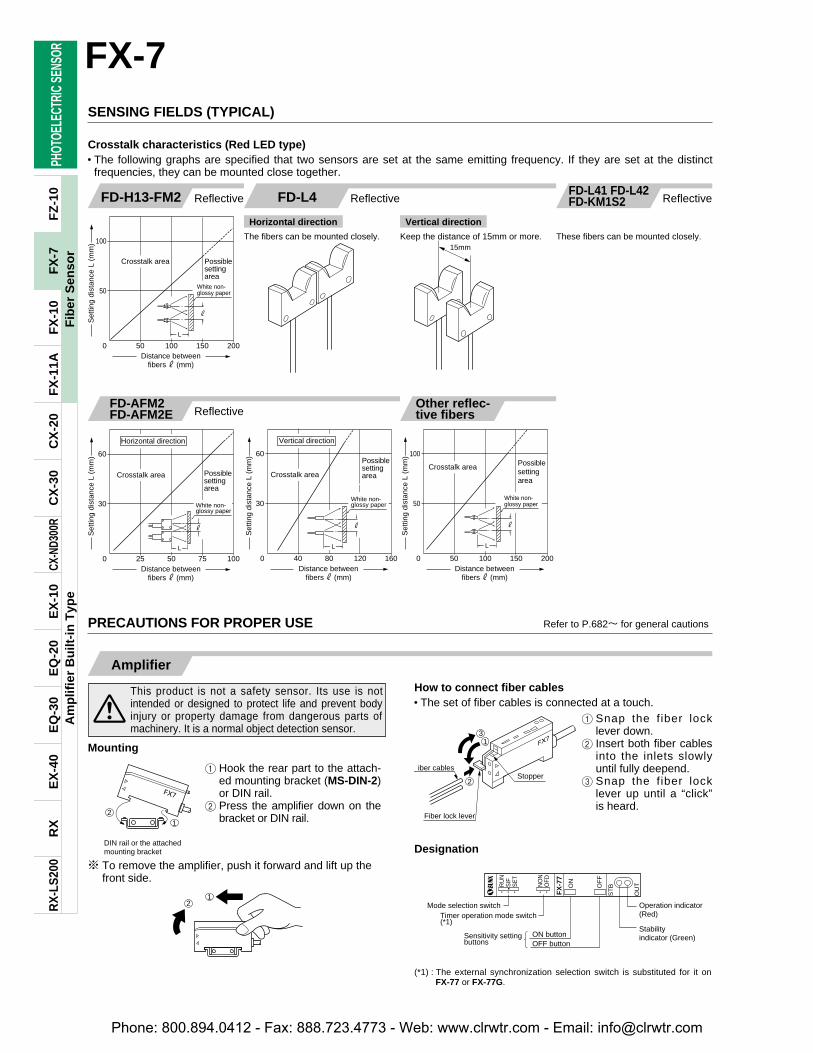
21
DIN rail or the attachedmounting bracket
RU
N
FX
-77
SIF
SE
T
NO
NO
FD
ON
OF
F
ST
B
OU
T
Mode selection switchTimer operation mode switch (*1)
Operation indicator (Red)
Stabilityindicator (Green)ON button
OFF buttonSensitivity setting buttons
Set
ting
dist
ance
L (
mm
)
Possiblesettingarea
Crosstalk area
100
50
500 200150100Distance between
fibers # (mm)
L
#
White non-glossy paper
Crosstalk area Possiblesettingarea
100
50
50 200150100Distance between
fibers # (mm)
Set
ting
dist
ance
L (
mm
)
L
#
White non-glossy paper
0
15mm
Possiblesettingarea
Crosstalk area
Horizontal direction
White non-glossy paper
#
L
60
30
25 1007550Distance between
fibers # (mm)
Set
ting
dist
ance
L (
mm
)
0
Crosstalk area
Possiblesettingarea
60
30
40 16012080Distance between
fibers # (mm)
L
#
White non-glossy paper
0
Set
ting
dist
ance
L (
mm
)
Vertical direction
2
13
Fiber lock lever
iber cablesStopper
12
PHOT
OELE
CTRI
C SE
NSOR
Am
plif
ier
Bu
ilt-i
n T
ype
RX
RX
-LS
200
EX
-40
EQ
-30
EQ
-20
EX
-10
CX-N
D300
RC
X-3
0C
X-2
0F
X-1
1AF
X-1
0F
Z-1
0FX-7
58
Fib
er S
enso
rF
X-7
SENSING FIELDS (TYPICAL)
FD-H13-FM2
Crosstalk characteristics (Red LED type)• The following graphs are specified that two sensors are set at the same emitting frequency. If they are set at the distinct
frequencies, they can be mounted close together.
Reflective
Other reflec-tive fibers
FD-L4 Reflective
FD-AFM2FD-AFM2E Reflective
FD-L41 FD-L42FD-KM1S2 Reflective
Horizontal direction
The fibers can be mounted closely.
Vertical direction
Keep the distance of 15mm or more. These fibers can be mounted closely.
PRECAUTIONS FOR PROPER USE Refer to P.682l for general cautions
Amplifier
This product is not a safety sensor. Its use is notintended or designed to protect life and prevent bodyinjury or property damage from dangerous parts ofmachinery. It is a normal object detection sensor.
Mounting
How to connect fiber cables• The set of fiber cables is connected at a touch.
1 Hook the rear part to the attach-ed mounting bracket (MS-DIN-2)or DIN rail.
2 Press the amplifier down on thebracket or DIN rail.
1 Snap the fiber locklever down.
2 Insert both fiber cablesinto the inlets slowlyuntil fully deepend.
3 Snap the fiber locklever up until a “click”is heard.
m To remove the amplifier, push it forward and lift up thefront side.
Designation
(*1) : The external synchronization selection switch is substituted for it onFX-77 or FX-77G.
Phone: 800.894.0412 - Fax: 888.723.4773 - Web: www.clrwtr.com - Email: [email protected]