![Grundfos SLV.80.100.110.2.51D.C Pompe : SLV.80.100.110 ......SLV.80.100.110.2.51D.C, 3*400 V, 50Hz P [kW] 0 2 4 6 8 10 NPSH [m] 0 2 4 6 8 10 P1 P2 782 123 303 499 DN100 DN80 180 18](https://static.fdocuments.net/doc/165x107/60c68b3b51e8137767287bd8/grundfos-slv80100110251dc-pompe-slv80100110-slv80100110251dc.jpg)
SL1, SLV pumps - Grundfos
160
GRUNDFOS PRODUCT GUIDE SL1, SLV pumps 1.5 to 15 hp 60 Hz
Transcript of SL1, SLV pumps - Grundfos
GRUNDFOS PRODUCT GUIDE
SL1, SLV pumps
1.5 to 15 hp60 Hz
Ta
ble
of c
on
ten
ts
2
SL1, SLV pumps
1. Introduction 3Introduction 3Applications 3Overall construction features 3
2. Performance range 4Performance range, SL1, SLV pumps 4
3. Identification 5Type key 5Nameplate 6
4. Selection of product 7Ordering a pump 7
5. Product range 8SL1 pump range 8SLV pump range 10
6. Variants 15List of variants 15
7. Construction 16SL1 16SLV 22Components and material specification 28
8. Product description 29Features 29Operating conditions 31Motor range 31Pump controllers 31Variable frequency drive operation 32Wiring diagrams 34
9. Curve charts and technical data 38How to read the curve charts 39Curve conditions 40Performance tests 40Certificates 40Witness test 40
10. Performance curves/technical data 42SL1.20.A25 42SL1.20.A30 48SL1.30.A30 54SL1.30.A40 66SL1.40.A40 78SL1.40.A60 84SLV.25.A25 90SLV.25.A30 96SLV.30.A30 102SLV.30.A40 122SLV.40.A40 142
11. Accessories 150Installation systems 150Other accessories 151Level controllers 152
12. Further product documentation 156WebCAPS 156WinCAPS 157

Intr
od
uc
tio
n
SL1, SLV pumps 1
1. Introduction
IntroductionThis product guide deals with Grundfos submersible wastewater and sewage pumps, types SL1 and SLV.
Two types of pumps are available:
• SL1 pumps with single-channel impeller
• SLV pumps with SuperVortex (free-flow) impeller.
Fig. 1 SL1 (single-channel) and SLV (SuperVortex) pumps
The pumps are free-flow (SuperVortex) and single-channel impeller pumps specifically designed for pumping sewage and wastewater in a wide range of municipal, private and industrial applications.
The pumps are made of resistant materials, such as cast iron and stainless steel. These materials ensure long and reliable operation.
The pumps are fitted with motors from 1.5 hp up and including 15 hp (1.1 to 11 kW). The motors are either 2- or 4-pole motors, depending on the motor size.
The free passage in the pumps is 2" to 4” (50 to 100 mm).
The pumps are available for:
• submerged installation on auto-coupling system
• submerged installation, free-standing.
ApplicationsTypical applications are transfer of liquids, such as:
• municipal wastewater
• wastewater with high content of fibres (SuperVortex impeller)
• drainage and surface water
• domestic wastewater
• industrial wastewater
• process and cooling water.
The pumps are ideal for the pumping of the above liquids from for instance:
• municipal network pumping stations
• inlet pumping stations in wastewater treatment plants
• primary clarification in wastewater treatment plants
• secondary clarification in wastewater treatment plants
• stormwater pumping stations
• public buildings
• residential buildings
• factories/industry.
Overall construction features• Moisture-proof cable plug connection made of
corrosion-resistant stainless steel with conductors embedded in polyurethane sealant
• Stainless steel clamp connection between motor housing and pump housing, for easy service.
• Power cable incorporating wires for thermal sensors in the motor windings
• No extra cable required for sensors in pumps with sensors
• Monitoring of operating conditions for pumps with sensors
• Moisture detector for continuous monitoring of motor enclosure and automatic cut-out in case of leakage
• Heavy-duty bearings greased for life
• Built for variable frequency drive operation
• Smooth pump surface prevents dirt and impurities from sticking to the pump
• Self-cleaning single-channel impeller with a long vane, thus reducing risk of jamming or clogging, or Super-Vortex impeller with high pumping efficiency and less downtime
• Explosion-proof motors for potentially explosive environments (FM-approved pumps)
• Motor in insulation class H (356 °F (180 °C), enclosure class IP68 with thermal sensor in each phase
• Temperature rise class A (1.5 to 8 hp) or class B (10 to 15 hp)
• Service-friendly design:- clamp connection between motor and pump housing- double mechanical cartridge shaft seal- cable connection to motor via plug.
• Motor built of highly efficient components, offering lower motor temperature and longer life.
SL
SL1
3

Pe
rform
an
ce
ran
ge
SL1, SLV pumps2
4
2. Performance range
Performance range, SL1, SLV pumpsThe figure below shows the performance range of SL1 and SLV sewage and wastewater pumps. It gives an overview of the various sizes and impeller types.
Note: For information about the performance range of each individual pump, see pages 42 to 142.
If your required duty point exceeds the performance range above, please see the Grundfos S range data booklet available in WebCAPS.
TM
04
75
78
22
10
30 40 50 100100 150 200 300 400 500 10001000 1500
Q [US GPM]
5
6
8
10
15
20
30
40
50
60
80
100
150
[ft]
H
2 3 4 5 6 7 8 9 1010 20 30 40 50 60 70 Q [l/s]
60 Hz
1
2
4
5
6
3
Pump type Curve No Pump type Curve No
SL1.20.A25.30
1
SLV.25.A25.30
4
SL1.20.A25.40 SLV.25.A25.40
SL1.20.A25.55 SLV.25.A25.55
SL1.20.A30.30 SLV.25.A30.30
SL1.20.A30.40 SLV.25.A30.40
SL1.20.A30.55 SLV.25.A30.55
SL1.30 2 SLV.30 5
SL1.40 3 SLV.40 6
Ide
nti
fic
ati
on
SL1, SLV pumps 3
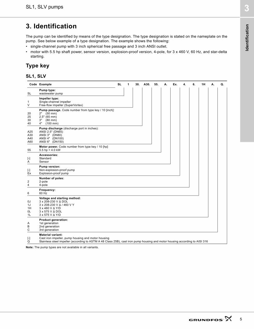
3. Identification
The pump can be identified by means of the type designation. The type designation is stated on the nameplate on the pump. See below example of a type designation. The example shows the following:
• single-channel pump with 3 inch spherical free passage and 3 inch ANSI outlet.
• motor with 5.5 hp shaft power, sensor version, explosion-proof version, 4-pole, for 3 x 460 V, 60 Hz, and star-delta starting.
Type key
SL1, SLV
Note: The pump types are not available in all variants.
Code Example SL 1 30. A30. 55. A. Ex. 4. 6. 1H A. Q.
SLPump type:wastewater pump
1V
Impeller type:Single-channel impellerFree-flow impeller (SuperVortex)
20253040
Pump passage. Code number from type key / 10 [inch]:2" (50 mm)2.5" (65 mm)3" (80 mm)4" (100 mm)
A25A30A40A60
Pump discharge (discharge port in inches):ANSI 2.5" (DN65)ANSI 3" (DN80)ANSI 4" (DN100)ANSI 6" (DN150)
55Motor power. Code number from type key / 10 [hp]5.5 hp = 4.0 kW
[-]A
Accessories:StandardSensor
[-]Ex
Pump version:Non-explosion-proof pumpExplosion-proof pump
24
Number of poles: 2-pole4-pole
6Frequency:60 Hz
0J1J1H0L1L
Voltage and starting method: 3 x 208-230 V ∆ DOL3 x 208-230 V ∆ / 460 V Y3 x 460 V ∆ Y/D3 x 575 V ∆ DOL3 x 575 V ∆ Y/D
ABC
Product generation:1st generation2nd generation3rd generation
[-]Q
Material variant:Cast iron impeller, pump housing and motor housingStainless steel impeller (according to ASTM A 48 Class 25B), cast iron pump housing and motor housing according to AISI 316
5
Ide
ntific
atio
n
SL1, SLV pumps3
6
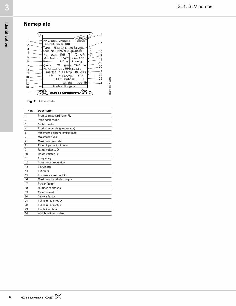
Nameplate
Fig. 2 Nameplate
TM
04
41
87
09
09
Pos. Description
1 Protection according to FM
2 Type designation
3 Serial number
4 Production code (year/month)
5 Maximum ambient temperature
6 Maximum head
7 Maximum flow rate
8 Rated input/output power
9 Rated voltage, D
10 Rated voltage, Y
11 Frequency
12 Country of production
13 CSA mark
14 FM mark
15 Enclosure class to IEC
16 Maximum installation depth
17 Power factor
18 Number of phases
19 Rated speed
20 Service factor
21 Full load current, D
22 Full load current, Y
23 Insulation class
24 Weight without cable
E
43
1
2
56
89
12
7
13
10
15
17
14
1819
22
16
21
23
20
2411
Se
lec
tio
n o
f p
rod
uc
t
SL1, SLV pumps 4
4. Selection of product
Ordering a pumpWhen ordering a pump, you need to take the following five aspects into consideration:
1. pump type
2. custom-built variation (option)
3. explosion-proof version
4. accessories
5. pump controller.
Pump typeUse the following table to identify which type of pump that best meets your needs. The table is for guidance only.
When you have selected the pump type, you can identify the specific pump that best meets your needs in section 5. Product range on page 8 and Type key on page 5. The list below is a detailed description of the product you get if you order the following pump:
• Pump as specified in the type key
• 33 ft (10 m) cable
• Paint: NSC 8005-R80B (dark grey), gloss code 35, thickness 100 μm
• Thermal switch in stator windings
• Tested according to Hydraulic Institute Centrifugal pump test 1.6-2000 acceptance level B.
See section 10. Performance curves/technical data for selection of a standard pump.
Note: Product-specific data for the pump can also be found in WebCAPS using the product number 96970895.
Custom-built variantsThe pumps can be customized to meet individual requirements. Many pump features and options are available for customization, such as explosion-proof versions, various cable lengths or special materials.
Variants can be seen in the table in section List of variants on page page 15. For requirements or designs outside the mentioned table, contact Grundfos.
Explosion-proof versionThe entire range is available in explosion-proof versions.
The SL1 and SLV pumps have the following explosion protection classification: Class I, Division 1, Groups C and D, T4, T3, IP68.
AccessoriesDepending on the installation type, accessories may be required. See section Installation systems on page 150 for selection of the correct accessories.
Note: Ordered accessories are not fitted from factory but needs to be fitted on site.
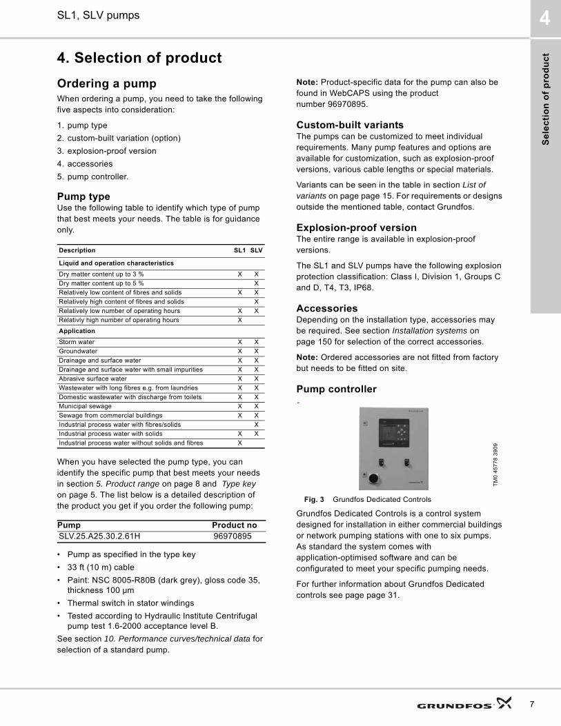
Pump controller
Fig. 3 Grundfos Dedicated Controls
Grundfos Dedicated Controls is a control system designed for installation in either commercial buildings or network pumping stations with one to six pumps. As standard the system comes with application-optimised software and can be configurated to meet your specific pumping needs.
For further information about Grundfos Dedicated controls see page page 31.
Description SL1 SLV
Liquid and operation characteristics
Dry matter content up to 3 % X X
Dry matter content up to 5 % X
Relatively low content of fibres and solids X X
Relatively high content of fibres and solids X
Relatively low number of operating hours X X
Relativly high number of operating hours X
Application
Storm water X X
Groundwater X X
Drainage and surface water X X
Drainage and surface water with small impurities X X
Abrasive surface water X X
Wastewater with long fibres e.g. from laundries X X
Domestic wastewater with discharge from toilets X X
Municipal sewage X X
Sewage from commercial buildings X X
Industrial process water with fibres/solids X
Industrial process water with solids X X
Industrial process water without solids and fibres X
Pump Product noSLV.25.A25.30.2.61H 96970895
TM
0 4
57
78
39
09
7
Pro
du
ct ra
ng
e
5
8
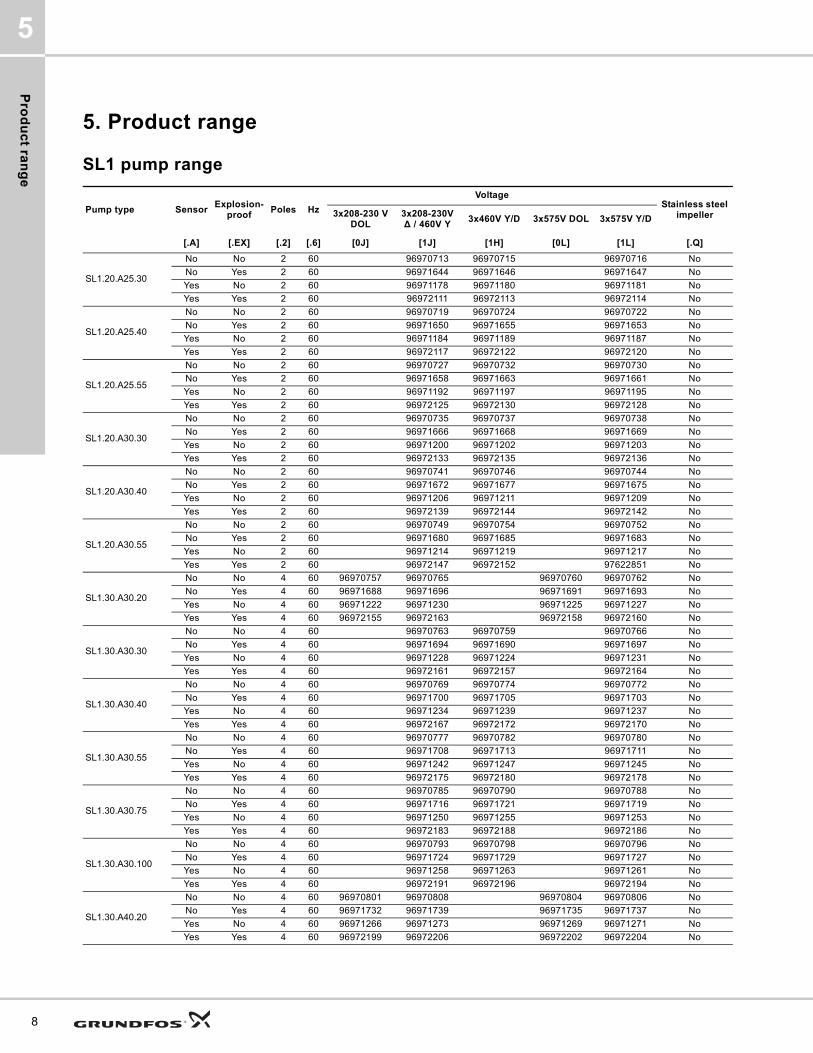
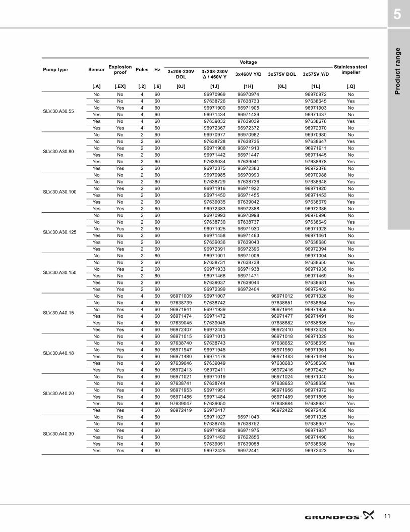
5. Product range
SL1 pump range
Pump type SensorExplosion-
proofPoles Hz
VoltageStainless steel
impeller3x208-230 V DOL
3x208-230V ∆ / 460V Y
3x460V Y/D 3x575V DOL 3x575V Y/D
[.A] [.EX] [.2] [.6] [0J] [1J] [1H] [0L] [1L] [.Q]
SL1.20.A25.30
No No 2 60 96970713 96970715 96970716 No
No Yes 2 60 96971644 96971646 96971647 No
Yes No 2 60 96971178 96971180 96971181 No
Yes Yes 2 60 96972111 96972113 96972114 No
SL1.20.A25.40
No No 2 60 96970719 96970724 96970722 No
No Yes 2 60 96971650 96971655 96971653 No
Yes No 2 60 96971184 96971189 96971187 No
Yes Yes 2 60 96972117 96972122 96972120 No
SL1.20.A25.55
No No 2 60 96970727 96970732 96970730 No
No Yes 2 60 96971658 96971663 96971661 No
Yes No 2 60 96971192 96971197 96971195 No
Yes Yes 2 60 96972125 96972130 96972128 No
SL1.20.A30.30
No No 2 60 96970735 96970737 96970738 No
No Yes 2 60 96971666 96971668 96971669 No
Yes No 2 60 96971200 96971202 96971203 No
Yes Yes 2 60 96972133 96972135 96972136 No
SL1.20.A30.40
No No 2 60 96970741 96970746 96970744 No
No Yes 2 60 96971672 96971677 96971675 No
Yes No 2 60 96971206 96971211 96971209 No
Yes Yes 2 60 96972139 96972144 96972142 No
SL1.20.A30.55
No No 2 60 96970749 96970754 96970752 No
No Yes 2 60 96971680 96971685 96971683 No
Yes No 2 60 96971214 96971219 96971217 No
Yes Yes 2 60 96972147 96972152 97622851 No
SL1.30.A30.20
No No 4 60 96970757 96970765 96970760 96970762 No
No Yes 4 60 96971688 96971696 96971691 96971693 No
Yes No 4 60 96971222 96971230 96971225 96971227 No
Yes Yes 4 60 96972155 96972163 96972158 96972160 No
SL1.30.A30.30
No No 4 60 96970763 96970759 96970766 No
No Yes 4 60 96971694 96971690 96971697 No
Yes No 4 60 96971228 96971224 96971231 No
Yes Yes 4 60 96972161 96972157 96972164 No
SL1.30.A30.40
No No 4 60 96970769 96970774 96970772 No
No Yes 4 60 96971700 96971705 96971703 No
Yes No 4 60 96971234 96971239 96971237 No
Yes Yes 4 60 96972167 96972172 96972170 No
SL1.30.A30.55
No No 4 60 96970777 96970782 96970780 No
No Yes 4 60 96971708 96971713 96971711 No
Yes No 4 60 96971242 96971247 96971245 No
Yes Yes 4 60 96972175 96972180 96972178 No
SL1.30.A30.75
No No 4 60 96970785 96970790 96970788 No
No Yes 4 60 96971716 96971721 96971719 No
Yes No 4 60 96971250 96971255 96971253 No
Yes Yes 4 60 96972183 96972188 96972186 No
SL1.30.A30.100
No No 4 60 96970793 96970798 96970796 No
No Yes 4 60 96971724 96971729 96971727 No
Yes No 4 60 96971258 96971263 96971261 No
Yes Yes 4 60 96972191 96972196 96972194 No
SL1.30.A40.20
No No 4 60 96970801 96970808 96970804 96970806 No
No Yes 4 60 96971732 96971739 96971735 96971737 No
Yes No 4 60 96971266 96971273 96971269 96971271 No
Yes Yes 4 60 96972199 96972206 96972202 96972204 No
Pro
du
ct
ran
ge
5
SL1.30.A40.30
No No 4 60 96970807 96970809 96970810 No
No Yes 4 60 96971738 96971740 96971741 No
Yes No 4 60 96971272 96971274 96971275 No
Yes Yes 4 60 96972205 96972207 96972208 No
SL1.30.A40.40
No No 4 60 96970813 96970818 96970816 No
No Yes 4 60 96971744 96971749 96971747 No
Yes No 4 60 96971278 96971283 96971281 No
Yes Yes 4 60 96972211 96972216 96972214 No
SL1.30.A40.55
No No 4 60 96970821 96970826 96970824 No
No Yes 4 60 96971752 96971757 96971755 No
Yes No 4 60 96971286 96971291 96971289 No
Yes Yes 4 60 96972219 96972224 96972222 No
SL1.30.A40.75
No No 4 60 96970829 96970834 96970832 No
No Yes 4 60 96971760 96971765 96971763 No
Yes No 4 60 96971294 96971299 96971297 No
Yes Yes 4 60 96972227 96972232 96972230 No
SL1.30.A40.100
No No 4 60 96970837 96970842 96970840 No
No Yes 4 60 96971768 96971773 96971771 No
Yes No 4 60 96971302 96971307 96971305 No
Yes Yes 4 60 96972235 96972240 96972238 No
SL1.40.A40.55
No No 4 60 96970845 96970855 96970848 No
No Yes 4 60 96971776 96971781 96971779 No
Yes No 4 60 96971310 96971315 96971313 No
Yes Yes 4 60 96972243 96972248 96972246 No
SL1.40.A40.75
No No 4 60 96970853 96970858 96970856 No
No Yes 4 60 96971784 96971789 96971787 No
Yes No 4 60 96971318 96971323 96971321 No
Yes Yes 4 60 96972251 96972256 96972254 No
SL1.40.A40.100
No No 4 60 96970861 96970866 96970864 No
No Yes 4 60 96971792 96971797 96971795 No
Yes No 4 60 96971326 96971331 96971329 No
Yes Yes 4 60 96972259 96972264 96972262 No
SL1.40.A60.55
No No 4 60 96970869 96970874 96970872 No
No Yes 4 60 96971800 96971805 96971803 No
Yes No 4 60 96971334 96971339 96971337 No
Yes Yes 4 60 96972267 96972272 96972270 No
SL1.40.A60.75
No No 4 60 96970877 96970882 96970880 No
No Yes 4 60 96971808 96971813 96971811 No
Yes No 4 60 96971342 96971347 96971345 No
Yes Yes 4 60 96972275 96972280 96972278 No
SL1.40.A60.100
No No 4 60 96970885 96970890 96970888 No
No Yes 4 60 96971816 96971821 96971819 No
Yes No 4 60 96971350 96971355 96971353 No
Yes Yes 4 60 96972283 96972288 96972286 No
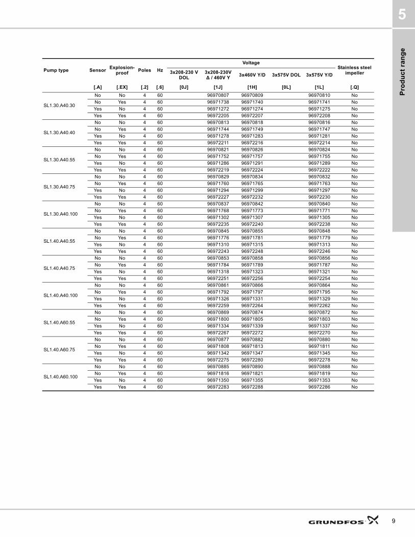
Pump type SensorExplosion-
proofPoles Hz
VoltageStainless steel
impeller3x208-230 V DOL
3x208-230V ∆ / 460V Y
3x460V Y/D 3x575V DOL 3x575V Y/D
[.A] [.EX] [.2] [.6] [0J] [1J] [1H] [0L] [1L] [.Q]
9

Pro
du
ct ra
ng
e
5
10
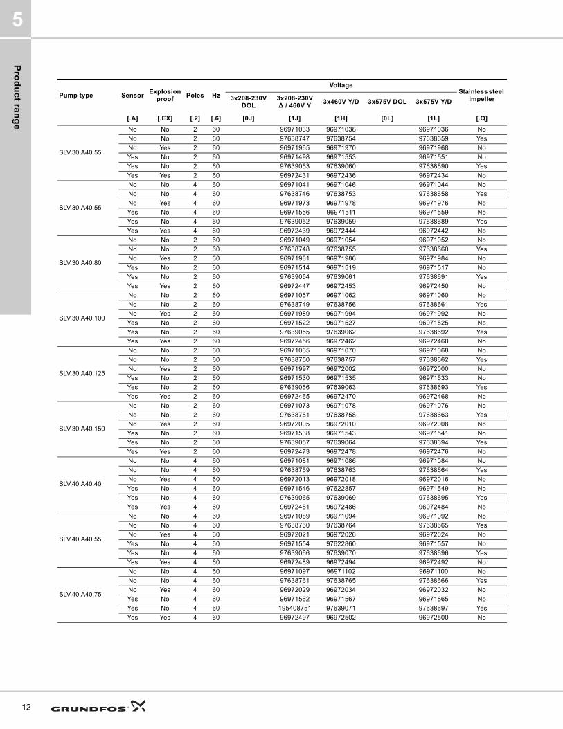
SLV pump range
Pump type SensorExplosion
proofPoles Hz
VoltageStainless steel
impeller 3x208-230V DOL
3x208-230V ∆ / 460V Y
3x460V Y/D 3x575V DOL 3x575V Y/D
[.A] [.EX] [.2] [.6] [0J] [1J] [1H] [0L] [1L] [.Q]
SLV.25.A25.30
No No 2 60 96970893 96970895 96970896 No
No Yes 2 60 96971824 96971826 96971827 No
Yes No 2 60 96971358 96971360 96971361 No
Yes Yes 2 60 96972291 96972293 96972294 No
SLV.25.A25.40
No No 2 60 96970899 96970904 96970902 No
No Yes 2 60 96971830 96971835 96971833 No
Yes No 2 60 96971364 96971369 96971367 No
Yes Yes 2 60 96972297 96972302 96972300 No
SLV.25.A25.55
No No 2 60 96970907 96970912 96970910 No
No Yes 2 60 96971838 96971843 96971841 No
Yes No 2 60 96971372 96971377 96971375 No
Yes Yes 2 60 96972305 96972310 96972308 No
SLV.25.A30.30
No No 2 60 96970915 96970917 96970918 No
No Yes 2 60 96971846 96971848 96971849 No
Yes No 2 60 96971380 96971382 96971383 No
Yes Yes 2 60 96972313 96972315 96972316 No
SLV.25.A30.40
No No 2 60 96970921 96970926 96970924 No
No Yes 2 60 96971852 96971857 96971855 No
Yes No 2 60 96971386 96971391 96971389 No
Yes Yes 2 60 96972319 96972324 96972322 No
SLV.25.A30.55
No No 2 60 96970929 96970934 96970932 No
No Yes 2 60 96971860 96971865 96971863 No
Yes No 2 60 96971394 96971399 96971397 No
Yes Yes 2 60 96972327 96972332 96972330 No
SLV.30.A30.15
No No 4 60 96970937 96970935 96970940 96970956 No
No No 4 60 97638699 97638722 97638628 97638641 Yes
No Yes 4 60 96971868 96971866 96971871 96971887 No
Yes No 4 60 96971402 96971400 96971405 96971421 No
Yes No 4 60 97639015 97639018 97638669 97638672 Yes
Yes Yes 4 60 96972335 96972333 96972338 96972354 No
SLV.30.A30.18
No No 4 60 96970943 96970941 96970946 96970958 No
No No 4 60 97638700 97638723 97638629 97638642 Yes
No Yes 4 60 96971874 96971872 96971877 96971889 No
Yes No 4 60 96971408 96971406 96971411 96971423 No
Yes No 4 60 97639016 97639019 97638670 97638673 Yes
Yes Yes 4 60 96972341 96972339 96972344 96972356 No
SLV.30.A30.20
No No 4 60 96970949 96970947 96970952 96970970 No
No No 4 60 97638721 97638724 97638630 97638643 Yes
No Yes 4 60 96971880 96971878 96971883 96971901 No
Yes No 4 60 96971414 96971412 96971417 96971435 No
Yes No 4 60 97639017 97639020 97638671 97638674 Yes
Yes Yes 4 60 96972347 96972345 96972350 96972368 No
SLV.30.A30.30
No No 4 60 96970955 96970963 96970953 No
No No 4 60 97638725 97638732 97638644 Yes
No Yes 4 60 96971886 96971894 96971884 No
Yes No 4 60 96971420 96971428 96971418 No
Yes No 4 60 97639031 97639038 97638675 Yes
Yes Yes 4 60 96972353 96972361 96972351 No
SLV.30.A30.55
No No 2 60 96970961 96970966 96970964 No
No No 2 60 97638727 97638734 97638646 Yes
No Yes 2 60 96971892 96971897 96971895 No
Yes No 2 60 96971426 96971431 96971429 No
Yes No 2 60 97639033 97639040 97638677 Yes
Yes Yes 2 60 96972359 96972364 96972362 No
Pro
du
ct
ran
ge
5
SLV.30.A30.55
No No 4 60 96970969 96970974 96970972 No
No No 4 60 97638726 97638733 97638645 Yes
No Yes 4 60 96971900 96971905 96971903 No
Yes No 4 60 96971434 96971439 96971437 No
Yes No 4 60 97639032 97639039 97638676 Yes
Yes Yes 4 60 96972367 96972372 96972370 No
SLV.30.A30.80
No No 2 60 96970977 96970982 96970980 No
No No 2 60 97638728 97638735 97638647 Yes
No Yes 2 60 96971908 96971913 96971911 No
Yes No 2 60 96971442 96971447 96971445 No
Yes No 2 60 97639034 97639041 97638678 Yes
Yes Yes 2 60 96972375 96972380 96972378 No
SLV.30.A30.100
No No 2 60 96970985 96970990 96970988 No
No No 2 60 97638729 97638736 97638648 Yes
No Yes 2 60 96971916 96971922 96971920 No
Yes No 2 60 96971450 96971455 96971453 No
Yes No 2 60 97639035 97639042 97638679 Yes
Yes Yes 2 60 96972383 96972388 96972386 No
SLV.30.A30.125
No No 2 60 96970993 96970998 96970996 No
No No 2 60 97638730 97638737 97638649 Yes
No Yes 2 60 96971925 96971930 96971928 No
Yes No 2 60 96971458 96971463 96971461 No
Yes No 2 60 97639036 97639043 97638680 Yes
Yes Yes 2 60 96972391 96972396 96972394 No
SLV.30.A30.150
No No 2 60 96971001 96971006 96971004 No
No No 2 60 97638731 97638738 97638650 Yes
No Yes 2 60 96971933 96971938 96971936 No
Yes No 2 60 96971466 96971471 96971469 No
Yes No 2 60 97639037 97639044 97638681 Yes
Yes Yes 2 60 96972399 96972404 96972402 No
SLV.30.A40.15
No No 4 60 96971009 96971007 96971012 96971026 No
No No 4 60 97638739 97638742 97638651 97638654 Yes
No Yes 4 60 96971941 96971939 96971944 96971958 No
Yes No 4 60 96971474 96971472 96971477 96971491 No
Yes No 4 60 97639045 97639048 97638682 97638685 Yes
Yes Yes 4 60 96972407 96972405 96972410 96972424 No
SLV.30.A40.18
No No 4 60 96971015 96971013 96971018 96971029 No
No No 4 60 97638740 97638743 97638652 97638655 Yes
No Yes 4 60 96971947 96971945 96971950 96971961 No
Yes No 4 60 96971480 96971478 96971483 96971494 No
Yes No 4 60 97639046 97639049 97638683 97638686 Yes
Yes Yes 4 60 96972413 96972411 96972416 96972427 No
SLV.30.A40.20
No No 4 60 96971021 96971019 96971024 96971040 No
No No 4 60 97638741 97638744 97638653 97638656 Yes
No Yes 4 60 96971953 96971951 96971956 96971972 No
Yes No 4 60 96971486 96971484 96971489 96971505 No
Yes No 4 60 97639047 97639050 97638684 97638687 Yes
Yes Yes 4 60 96972419 96972417 96972422 96972438 No
SLV.30.A40.30
No No 4 60 96971027 96971043 96971025 No
No No 4 60 97638745 97638752 97638657 Yes
No Yes 4 60 96971959 96971975 96971957 No
Yes No 4 60 96971492 97622856 96971490 No
Yes No 4 60 97639051 97639058 97638688 Yes
Yes Yes 4 60 96972425 96972441 96972423 No
Pump type SensorExplosion
proofPoles Hz
VoltageStainless steel
impeller 3x208-230V DOL
3x208-230V ∆ / 460V Y
3x460V Y/D 3x575V DOL 3x575V Y/D
[.A] [.EX] [.2] [.6] [0J] [1J] [1H] [0L] [1L] [.Q]
11
Pro
du
ct ra
ng
e
5
12
SLV.30.A40.55
No No 2 60 96971033 96971038 96971036 No
No No 2 60 97638747 97638754 97638659 Yes
No Yes 2 60 96971965 96971970 96971968 No
Yes No 2 60 96971498 96971553 96971551 No
Yes No 2 60 97639053 97639060 97638690 Yes
Yes Yes 2 60 96972431 96972436 96972434 No
SLV.30.A40.55
No No 4 60 96971041 96971046 96971044 No
No No 4 60 97638746 97638753 97638658 Yes
No Yes 4 60 96971973 96971978 96971976 No
Yes No 4 60 96971556 96971511 96971559 No
Yes No 4 60 97639052 97639059 97638689 Yes
Yes Yes 4 60 96972439 96972444 96972442 No
SLV.30.A40.80
No No 2 60 96971049 96971054 96971052 No
No No 2 60 97638748 97638755 97638660 Yes
No Yes 2 60 96971981 96971986 96971984 No
Yes No 2 60 96971514 96971519 96971517 No
Yes No 2 60 97639054 97639061 97638691 Yes
Yes Yes 2 60 96972447 96972453 96972450 No
SLV.30.A40.100
No No 2 60 96971057 96971062 96971060 No
No No 2 60 97638749 97638756 97638661 Yes
No Yes 2 60 96971989 96971994 96971992 No
Yes No 2 60 96971522 96971527 96971525 No
Yes No 2 60 97639055 97639062 97638692 Yes
Yes Yes 2 60 96972456 96972462 96972460 No
SLV.30.A40.125
No No 2 60 96971065 96971070 96971068 No
No No 2 60 97638750 97638757 97638662 Yes
No Yes 2 60 96971997 96972002 96972000 No
Yes No 2 60 96971530 96971535 96971533 No
Yes No 2 60 97639056 97639063 97638693 Yes
Yes Yes 2 60 96972465 96972470 96972468 No
SLV.30.A40.150
No No 2 60 96971073 96971078 96971076 No
No No 2 60 97638751 97638758 97638663 Yes
No Yes 2 60 96972005 96972010 96972008 No
Yes No 2 60 96971538 96971543 96971541 No
Yes No 2 60 97639057 97639064 97638694 Yes
Yes Yes 2 60 96972473 96972478 96972476 No
SLV.40.A40.40
No No 4 60 96971081 96971086 96971084 No
No No 4 60 97638759 97638763 97638664 Yes
No Yes 4 60 96972013 96972018 96972016 No
Yes No 4 60 96971546 97622857 96971549 No
Yes No 4 60 97639065 97639069 97638695 Yes
Yes Yes 4 60 96972481 96972486 96972484 No
SLV.40.A40.55
No No 4 60 96971089 96971094 96971092 No
No No 4 60 97638760 97638764 97638665 Yes
No Yes 4 60 96972021 96972026 96972024 No
Yes No 4 60 96971554 97622860 96971557 No
Yes No 4 60 97639066 97639070 97638696 Yes
Yes Yes 4 60 96972489 96972494 96972492 No
SLV.40.A40.75
No No 4 60 96971097 96971102 96971100 No
No No 4 60 97638761 97638765 97638666 Yes
No Yes 4 60 96972029 96972034 96972032 No
Yes No 4 60 96971562 96971567 96971565 No
Yes No 4 60 195408751 97639071 97638697 Yes
Yes Yes 4 60 96972497 96972502 96972500 No
Pump type SensorExplosion
proofPoles Hz
VoltageStainless steel
impeller 3x208-230V DOL
3x208-230V ∆ / 460V Y
3x460V Y/D 3x575V DOL 3x575V Y/D
[.A] [.EX] [.2] [.6] [0J] [1J] [1H] [0L] [1L] [.Q]

Pro
du
ct
ran
ge
5
SLV.40.A40.100
No No 4 60 96971105 96971110 96971108 No
No No 4 60 97638762 97638766 97638667 Yes
No Yes 4 60 96972037 96972043 96972041 No
Yes No 4 60 96971570 96971575 96971573 No
Yes No 4 60 97639068 97639072 97638698 Yes
Yes Yes 4 60 96972505 96972510 96972508 No
Pump type SensorExplosion
proofPoles Hz
VoltageStainless steel
impeller 3x208-230V DOL
3x208-230V ∆ / 460V Y
3x460V Y/D 3x575V DOL 3x575V Y/D
[.A] [.EX] [.2] [.6] [0J] [1J] [1H] [0L] [1L] [.Q]
13
Pro
du
ct ra
ng
e
5
14
Va
ria
nts
SL1, SLV pumps 6
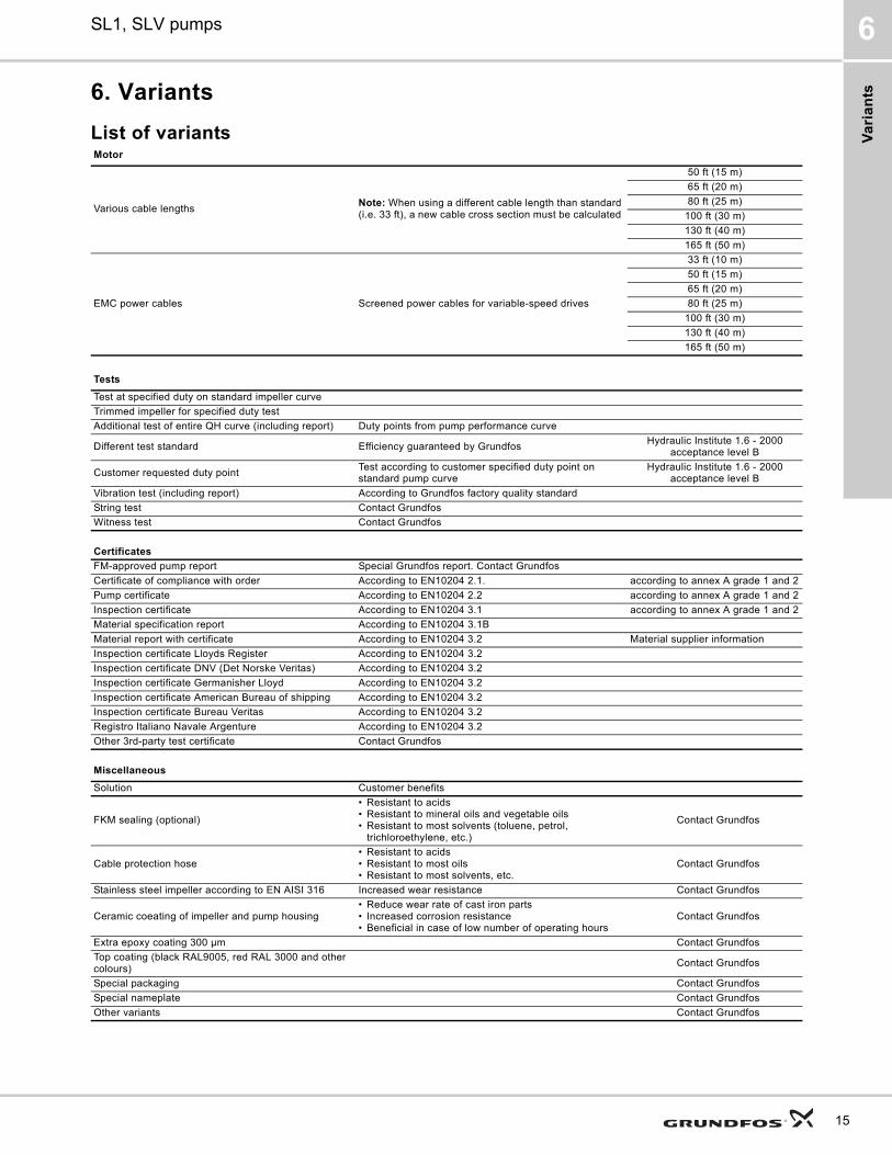
6. Variants
List of variantsMotor
Various cable lengthsNote: When using a different cable length than standard (i.e. 33 ft), a new cable cross section must be calculated
50 ft (15 m)
65 ft (20 m)
80 ft (25 m)
100 ft (30 m)
130 ft (40 m)
165 ft (50 m)
EMC power cables Screened power cables for variable-speed drives
33 ft (10 m)
50 ft (15 m)
65 ft (20 m)
80 ft (25 m)
100 ft (30 m)
130 ft (40 m)
165 ft (50 m)
Tests
Test at specified duty on standard impeller curve
Trimmed impeller for specified duty test
Additional test of entire QH curve (including report) Duty points from pump performance curve
Different test standard Efficiency guaranteed by GrundfosHydraulic Institute 1.6 - 2000
acceptance level B
Customer requested duty pointTest according to customer specified duty point on standard pump curve
Hydraulic Institute 1.6 - 2000 acceptance level B
Vibration test (including report) According to Grundfos factory quality standard
String test Contact Grundfos
Witness test Contact Grundfos
Certificates
FM-approved pump report Special Grundfos report. Contact Grundfos
Certificate of compliance with order According to EN10204 2.1. according to annex A grade 1 and 2
Pump certificate According to EN10204 2.2 according to annex A grade 1 and 2
Inspection certificate According to EN10204 3.1 according to annex A grade 1 and 2
Material specification report According to EN10204 3.1B
Material report with certificate According to EN10204 3.2 Material supplier information
Inspection certificate Lloyds Register According to EN10204 3.2
Inspection certificate DNV (Det Norske Veritas) According to EN10204 3.2
Inspection certificate Germanisher Lloyd According to EN10204 3.2
Inspection certificate American Bureau of shipping According to EN10204 3.2
Inspection certificate Bureau Veritas According to EN10204 3.2
Registro Italiano Navale Argenture According to EN10204 3.2
Other 3rd-party test certificate Contact Grundfos
Miscellaneous
Solution Customer benefits
FKM sealing (optional)
• Resistant to acids• Resistant to mineral oils and vegetable oils• Resistant to most solvents (toluene, petrol,
trichloroethylene, etc.)
Contact Grundfos
Cable protection hose• Resistant to acids• Resistant to most oils• Resistant to most solvents, etc.
Contact Grundfos
Stainless steel impeller according to EN AISI 316 Increased wear resistance Contact Grundfos
Ceramic coeating of impeller and pump housing• Reduce wear rate of cast iron parts• Increased corrosion resistance• Beneficial in case of low number of operating hours
Contact Grundfos
Extra epoxy coating 300 μm Contact Grundfos
Top coating (black RAL9005, red RAL 3000 and other colours)
Contact Grundfos
Special packaging Contact Grundfos
Special nameplate Contact Grundfos
Other variants Contact Grundfos
15
Co
ns
truc
tion
SL1, SLV pumps7
16
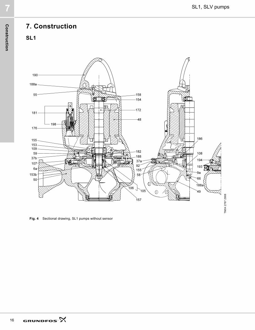
7. Construction
SL1
Fig. 4 Sectional drawing, SL1 pumps without sensor
TM
04
27
87
29
08
Co
ns
tru
cti
on
SL1, SLV pumps 7
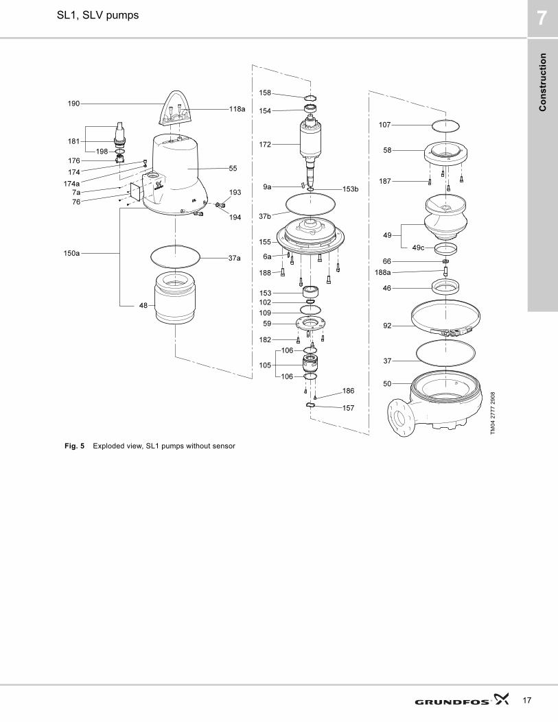
Fig. 5 Exploded view, SL1 pumps without sensor
TM
04
27
77
29
08
17

Co
ns
truc
tion
SL1, SLV pumps7
18
Fig. 6 Sectional drawing, SL1 pumps EX version
TM
04
75
75
211
0
Co
ns
tru
cti
on
SL1, SLV pumps 7
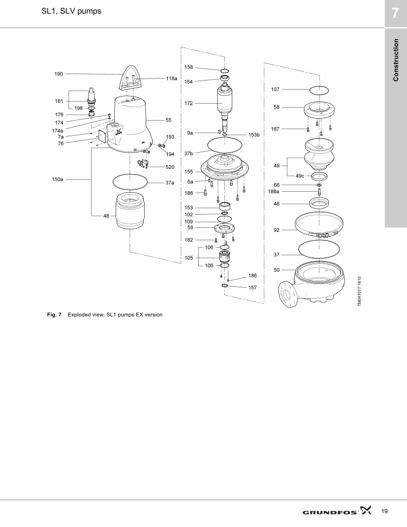
Fig. 7 Exploded view, SL1 pumps EX version
TM
04
70
77
16
10
19

Co
ns
truc
tion
SL1, SLV pumps7
20
Fig. 8 Sectional drawing, SL1 pumps with sensor
TM
04
27
88
29
08
Co
ns
tru
cti
on
SL1, SLV pumps 7
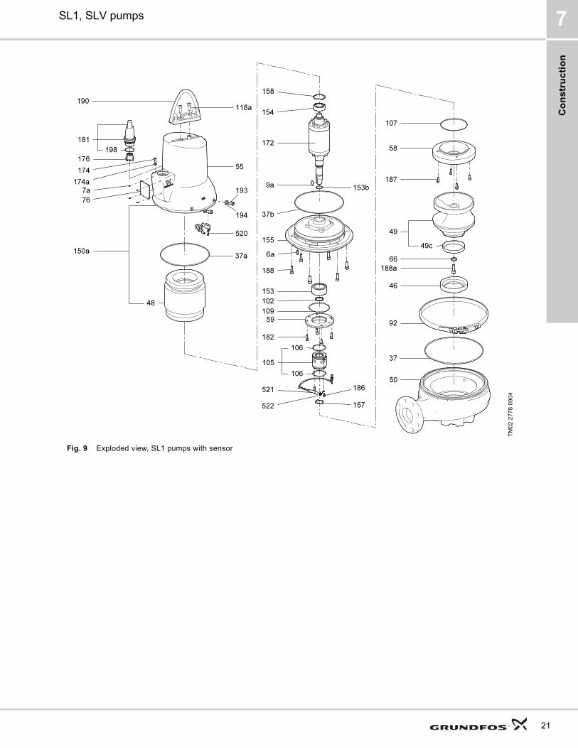
Fig. 9 Exploded view, SL1 pumps with sensor
TM
02
27
78
09
04
21
Co
ns
truc
tion
SL1, SLV pumps7
22
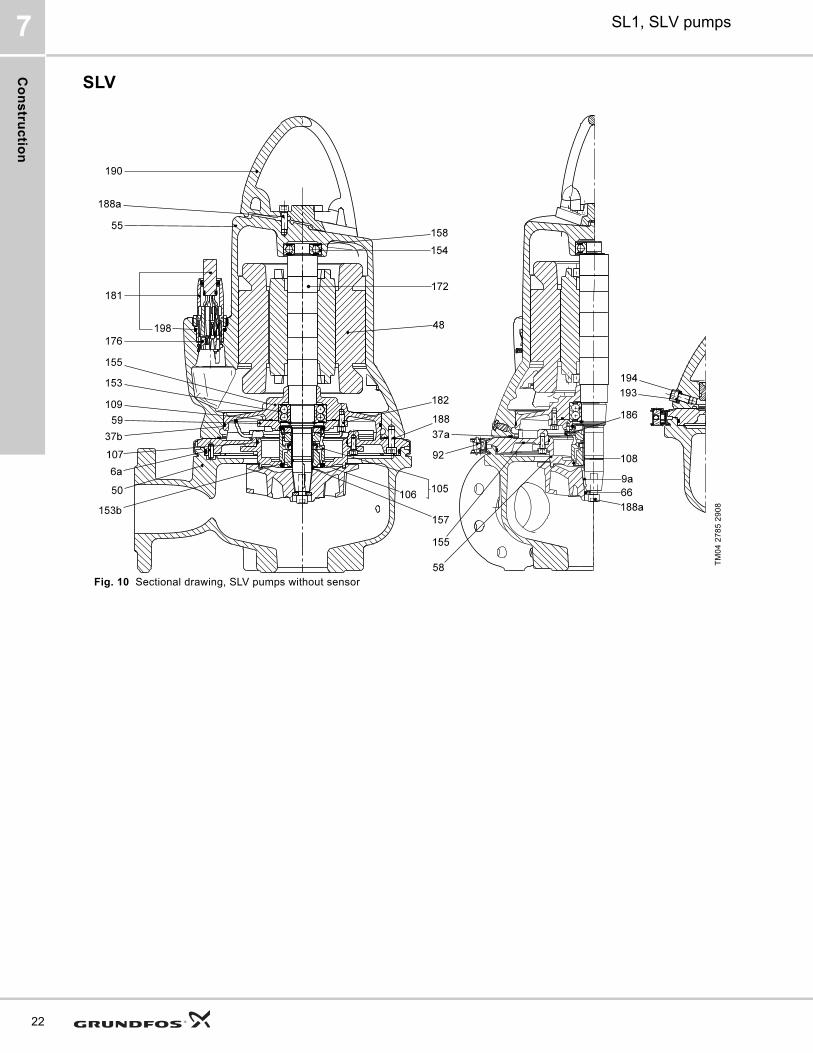
SLV
Fig. 10 Sectional drawing, SLV pumps without sensor
TM
04
27
85
29
08
Co
ns
tru
cti
on
SL1, SLV pumps 7
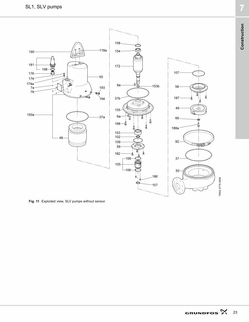
Fig. 11 Exploded view, SLV pumps without sensor
TM
04
27
79
29
08
23
Co
ns
truc
tion
SL1, SLV pumps7
24
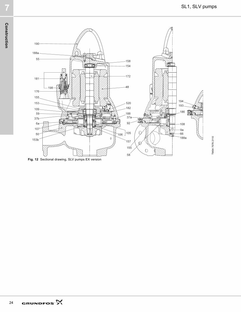
Fig. 12 Sectional drawing, SLV pumps EX version
TM
04
75
76
211
0
Co
ns
tru
cti
on
SL1, SLV pumps 7
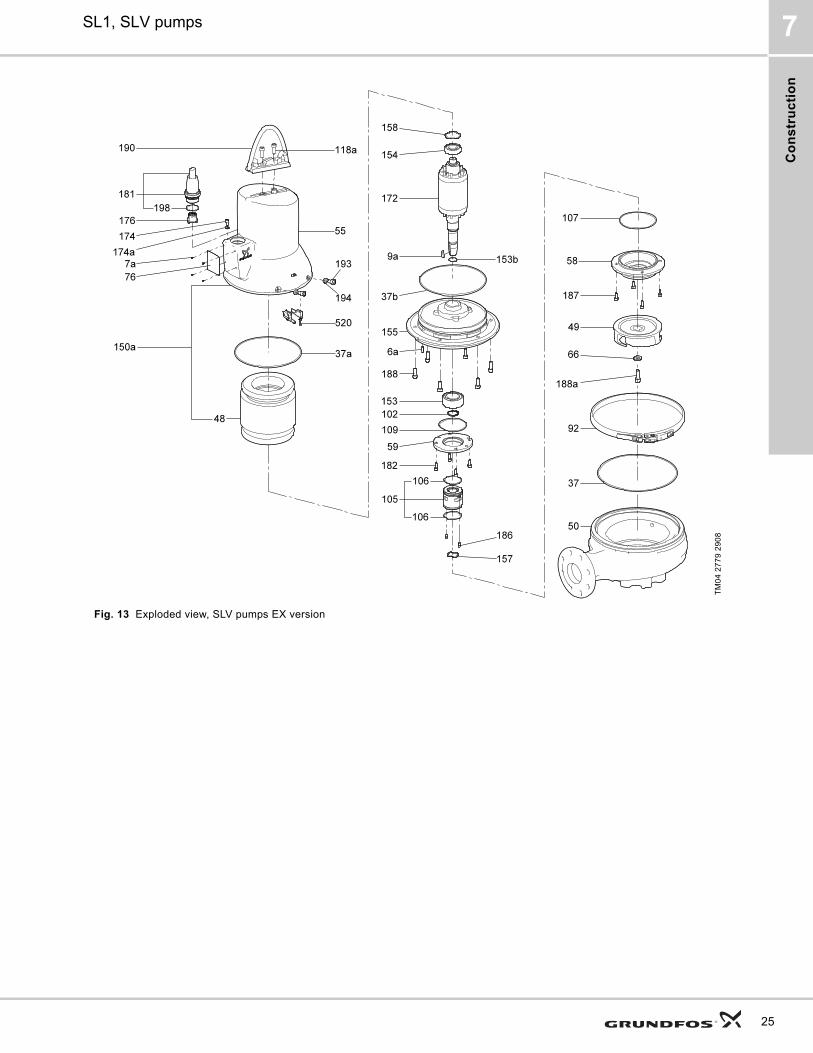
Fig. 13 Exploded view, SLV pumps EX version
TM
04
27
79
29
08
25
Co
ns
truc
tion
SL1, SLV pumps7
26
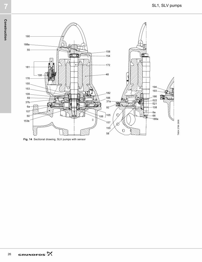
Fig. 14 Sectional drawing, SLV pumps with sensor
TM
04
27
86
29
08
Co
ns
tru
cti
on
SL1, SLV pumps 7
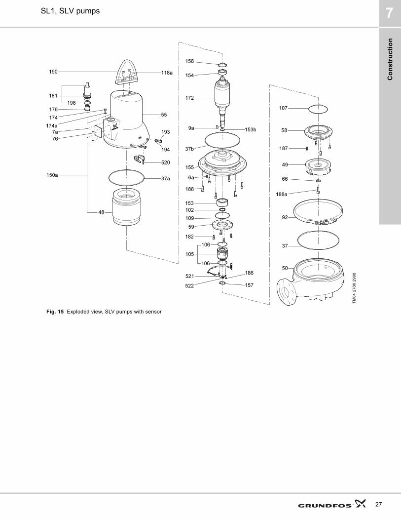
Fig. 15 Exploded view, SLV pumps with sensor
TM
04
27
80
29
08
27
Co
ns
truc
tion
SL1, SLV pumps7
28
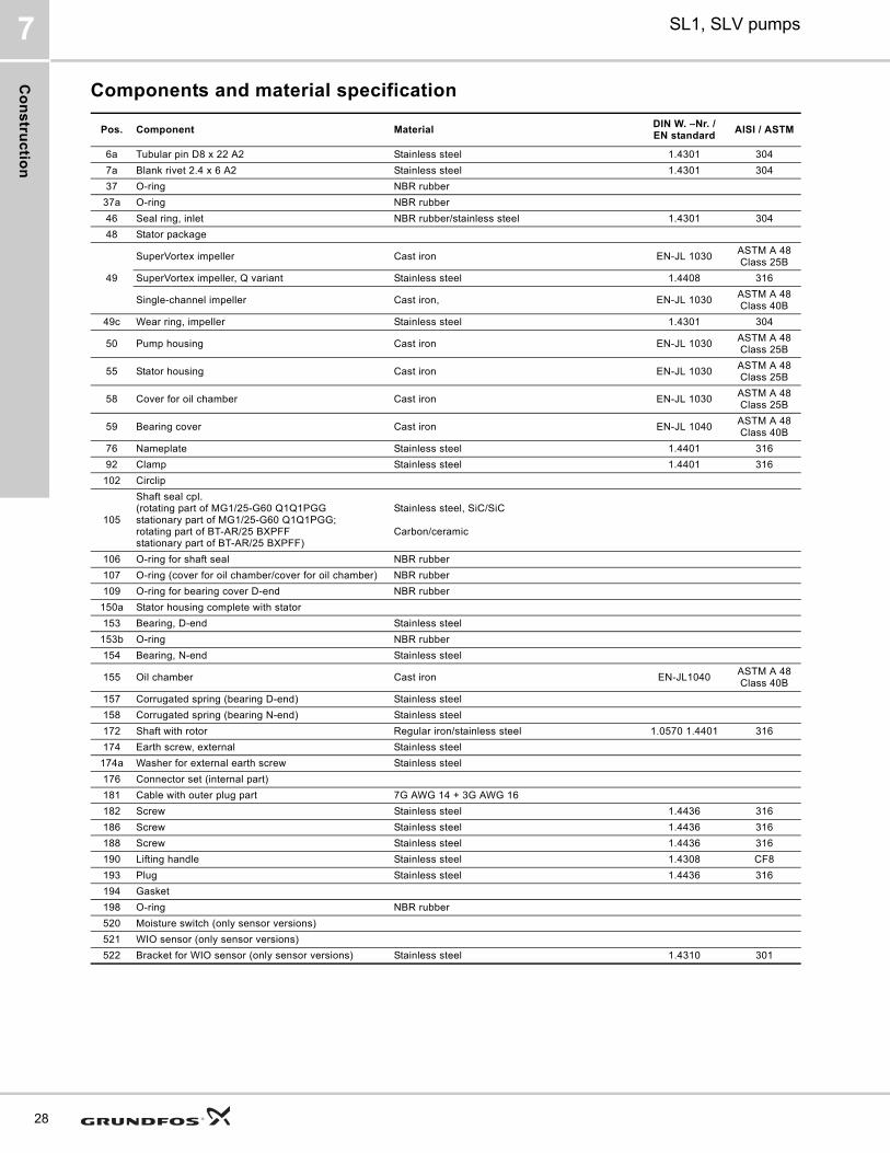
Components and material specification
Pos. Component MaterialDIN W. –Nr. /EN standard
AISI / ASTM
6a Tubular pin D8 x 22 A2 Stainless steel 1.4301 304
7a Blank rivet 2.4 x 6 A2 Stainless steel 1.4301 304
37 O-ring NBR rubber
37a O-ring NBR rubber
46 Seal ring, inlet NBR rubber/stainless steel 1.4301 304
48 Stator package
49
SuperVortex impeller Cast iron EN-JL 1030ASTM A 48 Class 25B
SuperVortex impeller, Q variant Stainless steel 1.4408 316
Single-channel impeller Cast iron, EN-JL 1030ASTM A 48 Class 40B
49c Wear ring, impeller Stainless steel 1.4301 304
50 Pump housing Cast iron EN-JL 1030ASTM A 48 Class 25B
55 Stator housing Cast iron EN-JL 1030ASTM A 48 Class 25B
58 Cover for oil chamber Cast iron EN-JL 1030ASTM A 48 Class 25B
59 Bearing cover Cast iron EN-JL 1040ASTM A 48 Class 40B
76 Nameplate Stainless steel 1.4401 316
92 Clamp Stainless steel 1.4401 316
102 Circlip
105
Shaft seal cpl.(rotating part of MG1/25-G60 Q1Q1PGG stationary part of MG1/25-G60 Q1Q1PGG; rotating part of BT-AR/25 BXPFFstationary part of BT-AR/25 BXPFF)
Stainless steel, SiC/SiC
Carbon/ceramic
106 O-ring for shaft seal NBR rubber
107 O-ring (cover for oil chamber/cover for oil chamber) NBR rubber
109 O-ring for bearing cover D-end NBR rubber
150a Stator housing complete with stator
153 Bearing, D-end Stainless steel
153b O-ring NBR rubber
154 Bearing, N-end Stainless steel
155 Oil chamber Cast iron EN-JL1040ASTM A 48 Class 40B
157 Corrugated spring (bearing D-end) Stainless steel
158 Corrugated spring (bearing N-end) Stainless steel
172 Shaft with rotor Regular iron/stainless steel 1.0570 1.4401 316
174 Earth screw, external Stainless steel
174a Washer for external earth screw Stainless steel
176 Connector set (internal part)
181 Cable with outer plug part 7G AWG 14 + 3G AWG 16
182 Screw Stainless steel 1.4436 316
186 Screw Stainless steel 1.4436 316
188 Screw Stainless steel 1.4436 316
190 Lifting handle Stainless steel 1.4308 CF8
193 Plug Stainless steel 1.4436 316
194 Gasket
198 O-ring NBR rubber
520 Moisture switch (only sensor versions)
521 WIO sensor (only sensor versions)
522 Bracket for WIO sensor (only sensor versions) Stainless steel 1.4310 301
Pro
du
ct
de
sc
rip
tio
n
SL1, SLV pumps 8
8. Product description
Features
Ball bearings
The bearings are greased for life.
Main bearings:
Support bearings: Single-row deep-groove ball bearing.
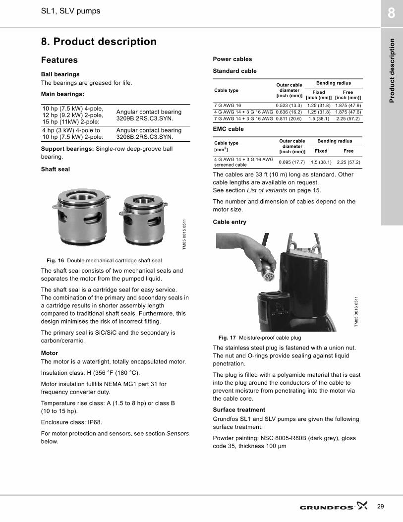
Shaft seal
Fig. 16 Double mechanical cartridge shaft seal
The shaft seal consists of two mechanical seals and separates the motor from the pumped liquid.
The shaft seal is a cartridge seal for easy service. The combination of the primary and secondary seals in a cartridge results in shorter assembly length compared to traditional shaft seals. Furthermore, this design minimises the risk of incorrect fitting.
The primary seal is SiC/SiC and the secondary is carbon/ceramic.
Motor
The motor is a watertight, totally encapsulated motor.
Insulation class: H (356 °F (180 °C).
Motor insulation fullfils NEMA MG1 part 31 for frequency converter duty.
Temperature rise class: A (1.5 to 8 hp) or class B (10 to 15 hp).
Enclosure class: IP68.
For motor protection and sensors, see section Sensors below.
Power cables
Standard cable
EMC cable
The cables are 33 ft (10 m) long as standard. Other cable lengths are available on request. See section List of variants on page 15.
The number and dimension of cables depend on the motor size.
Cable entry
Fig. 17 Moisture-proof cable plug
The stainless steel plug is fastened with a union nut. The nut and O-rings provide sealing against liquid penetration.
The plug is filled with a polyamide material that is cast into the plug around the conductors of the cable to prevent moisture from penetrating into the motor via the cable core.
Surface treatment
Grundfos SL1 and SLV pumps are given the following surface treatment:
Powder painting: NSC 8005-R80B (dark grey), gloss code 35, thickness 100 μm
10 hp (7.5 kW) 4-pole, 12 hp (9.2 kW) 2-pole, 15 hp (11kW) 2-pole:
Angular contact bearing 3209B.2RS.C3.SYN.
4 hp (3 kW) 4-pole to 10 hp (7.5 kW) 2-pole:
Angular contact bearing 3208B.2RS.C3.SYN.
TM
05
00
15
05
11
Cable typeOuter cable
diameter[inch (mm)]
Bending radius
Fixed[inch (mm)]
Free[inch (mm)]
7 G AWG 16 0.523 (13.3) 1.25 (31.8) 1.875 (47.6)
4 G AWG 14 + 3 G 16 AWG 0.636 (16.2) 1.25 (31.8) 1.875 (47.6)
7 G AWG 14 + 3 G 16 AWG 0.811 (20.6) 1.5 (38.1) 2.25 (57.2)
Cable type
[mm2]
Outer cable diameter
[inch (mm)]
Bending radius
Fixed Free
4 G AWG 14 + 3 G 16 AWG screened cable
0.695 (17.7) 1.5 (38.1) 2.25 (57.2)
TM
05
00
16
05
11
29
Pro
du
ct d
es
crip
tion
SL1, SLV pumps8
30
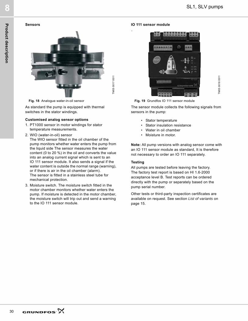
Sensors
Fig. 18 Analogue water-in-oil sensor
As standard the pump is equipped with thermal switches in the stator windings.
Customised analog sensor options
1. PT1000 sensor in motor windings for stator temperature measurements.
2. WIO (water-in-oil) sensorThe WIO sensor fitted in the oil chamber of the pump monitors whether water enters the pump from the liquid side The sensor measures the water content (0 to 20 %) in the oil and converts the value into an analog current signal which is sent to an IO 111 sensor module. It also sends a signal if the water content is outside the normal range (warning), or if there is air in the oil chamber (alarm). The sensor is fitted in a stainless steel tube for mechanical protection.
3. Moisture switch. The moisture switch fitted in the motor chamber monitors whether water enters the pump. If moisture is detected in the motor chamber, the moisture switch will trip out and send a warning to the IO 111 sensor module.
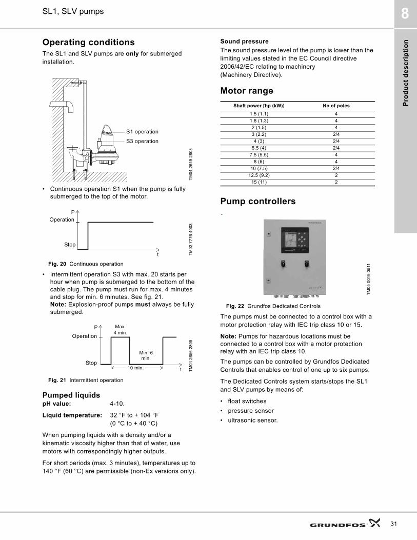
IO 111 sensor module
Fig. 19 Grundfos IO 111 sensor module
The sensor module collects the following signals from sensors in the pump:
Note: All pump versions with analog sensor come with an IO 111 sensor module as standard, It is therefore not necessary to order an IO 111 separately.
Testing
All pumps are tested before leaving the factory. The factory test report is based on HI 1.6-2000 acceptance level B. Test reports can be ordered directly with the pump or separately based on the pump serial number.
Other tests or third-party inspection certificates are available on request. See section List of variants on page 15.
TM
05
00
17
05
11
TM
05
00
18
05
11
• Stator temperature• Stator insulation resistance• Water in oil chamber• Moisture in motor.
Pro
du
ct
de
sc
rip
tio
n
SL1, SLV pumps 8
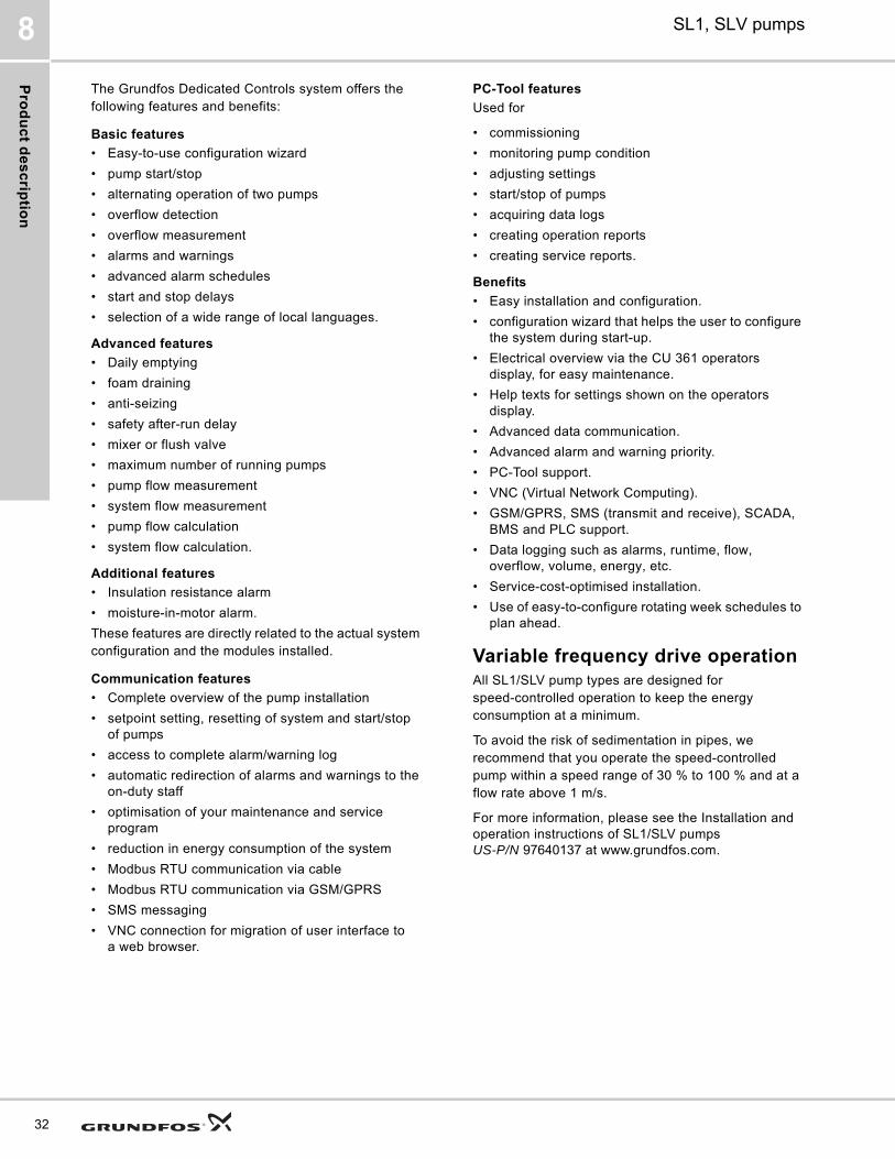
Operating conditionsThe SL1 and SLV pumps are only for submerged installation.
• Continuous operation S1 when the pump is fully submerged to the top of the motor.
Fig. 20 Continuous operation
• Intermittent operation S3 with max. 20 starts per hour when pump is submerged to the bottom of the cable plug. The pump must run for max. 4 minutes and stop for min. 6 minutes. See fig. 21.Note: Explosion-proof pumps must always be fully submerged.
Fig. 21 Intermittent operation
Pumped liquidspH value: 4-10.
Liquid temperature: 32 °F to + 104 °F (0 °C to + 40 °C)
When pumping liquids with a density and/or a kinematic viscosity higher than that of water, use motors with correspondingly higher outputs.
For short periods (max. 3 minutes), temperatures up to 140 °F (60 °C) are permissible (non-Ex versions only).
Sound pressure
The sound pressure level of the pump is lower than the limiting values stated in the EC Council directive 2006/42/EC relating to machinery (Machinery Directive).
Motor range
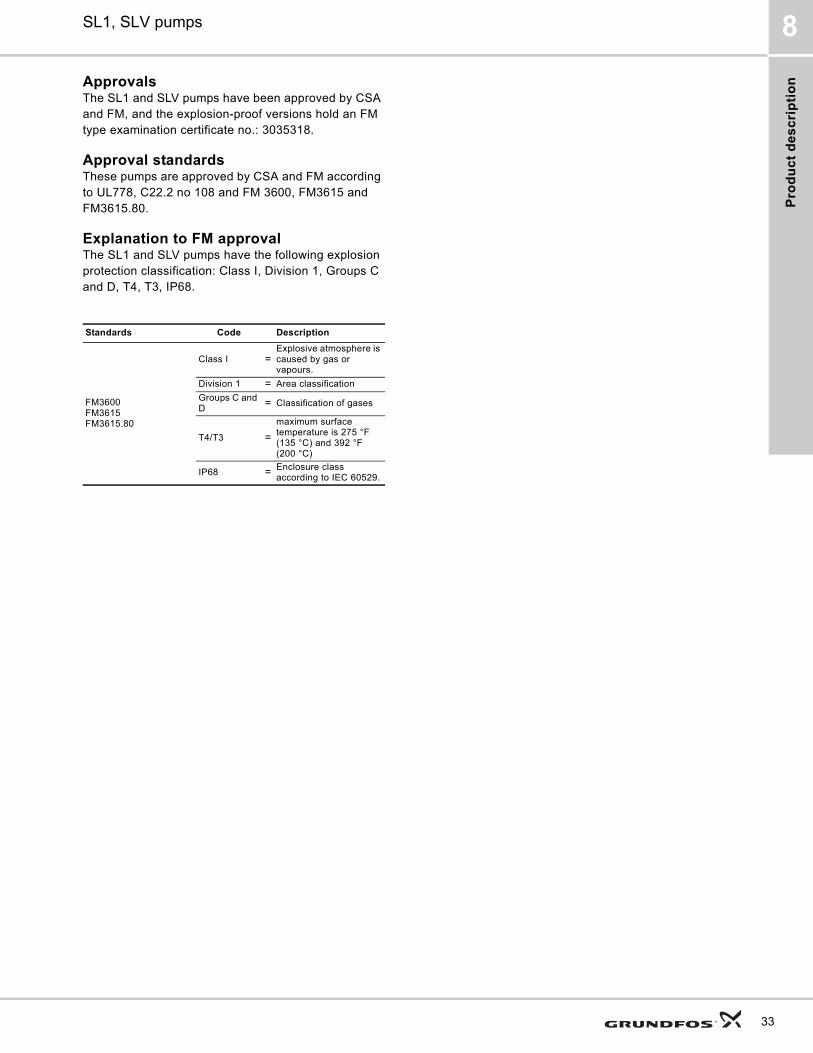
Pump controllers
Fig. 22 Grundfos Dedicated Controls
The pumps must be connected to a control box with a motor protection relay with IEC trip class 10 or 15.
Note: Pumps for hazardous locations must be connected to a control box with a motor protection relay with an IEC trip class 10.
The pumps can be controlled by Grundfos Dedicated Controls that enables control of one up to six pumps.
The Dedicated Controls system starts/stops the SL1 and SLV pumps by means of:
• float switches
• pressure sensor
• ultrasonic sensor.
TM
04
26
49
28
08
TM
02
77
76
40
03
TM
04
26
56
28
08
S1 operation
S3 operation
P
t
Stop
Operation
10 min
P
t
4 min 6 min
Operation
Stop
Max. 4 min.
Min. 6 min.
10 min.
Shaft power [hp (kW)] No of poles
1.5 (1.1) 4
1.8 (1.3) 4
2 (1.5) 4
3 (2.2) 2/4
4 (3) 2/4
5.5 (4) 2/4
7.5 (5.5) 4
8 (6) 4
10 (7.5) 2/4
12.5 (9.2) 2
15 (11) 2
TM
05
00
19
05
11
31
Pro
du
ct d
es
crip
tion
SL1, SLV pumps8
32
The Grundfos Dedicated Controls system offers the following features and benefits:
Basic features
• Easy-to-use configuration wizard
• pump start/stop
• alternating operation of two pumps
• overflow detection
• overflow measurement
• alarms and warnings
• advanced alarm schedules
• start and stop delays
• selection of a wide range of local languages.
Advanced features
• Daily emptying
• foam draining
• anti-seizing
• safety after-run delay
• mixer or flush valve
• maximum number of running pumps
• pump flow measurement
• system flow measurement
• pump flow calculation
• system flow calculation.
Additional features
• Insulation resistance alarm
• moisture-in-motor alarm.
These features are directly related to the actual system configuration and the modules installed.
Communication features
• Complete overview of the pump installation
• setpoint setting, resetting of system and start/stop of pumps
• access to complete alarm/warning log
• automatic redirection of alarms and warnings to the on-duty staff
• optimisation of your maintenance and service program
• reduction in energy consumption of the system
• Modbus RTU communication via cable
• Modbus RTU communication via GSM/GPRS
• SMS messaging
• VNC connection for migration of user interface to a web browser.
PC-Tool features
Used for
• commissioning
• monitoring pump condition
• adjusting settings
• start/stop of pumps
• acquiring data logs
• creating operation reports
• creating service reports.
Benefits
• Easy installation and configuration.
• configuration wizard that helps the user to configure the system during start-up.
• Electrical overview via the CU 361 operators display, for easy maintenance.
• Help texts for settings shown on the operators display.
• Advanced data communication.
• Advanced alarm and warning priority.
• PC-Tool support.
• VNC (Virtual Network Computing).
• GSM/GPRS, SMS (transmit and receive), SCADA, BMS and PLC support.
• Data logging such as alarms, runtime, flow, overflow, volume, energy, etc.
• Service-cost-optimised installation.
• Use of easy-to-configure rotating week schedules to plan ahead.
Variable frequency drive operation All SL1/SLV pump types are designed for speed-controlled operation to keep the energy consumption at a minimum.
To avoid the risk of sedimentation in pipes, we recommend that you operate the speed-controlled pump within a speed range of 30 % to 100 % and at a flow rate above 1 m/s.
For more information, please see the Installation and operation instructions of SL1/SLV pumps US-P/N 97640137 at www.grundfos.com.
Pro
du
ct
de
sc
rip
tio
n
SL1, SLV pumps 8
ApprovalsThe SL1 and SLV pumps have been approved by CSA and FM, and the explosion-proof versions hold an FM type examination certificate no.: 3035318.
Approval standardsThese pumps are approved by CSA and FM according to UL778, C22.2 no 108 and FM 3600, FM3615 and FM3615.80.
Explanation to FM approvalThe SL1 and SLV pumps have the following explosion protection classification: Class I, Division 1, Groups C and D, T4, T3, IP68.
Standards Code Description
FM3600FM3615FM3615.80
Class I =Explosive atmosphere is caused by gas or vapours.
Division 1 = Area classification
Groups C and D = Classification of gases
T4/T3 =
maximum surface temperature is 275 °F (135 °C) and 392 °F (200 °C)
IP68 = Enclosure class according to IEC 60529.
33
Pro
du
ct d
es
crip
tion
SL1, SLV pumps8
34
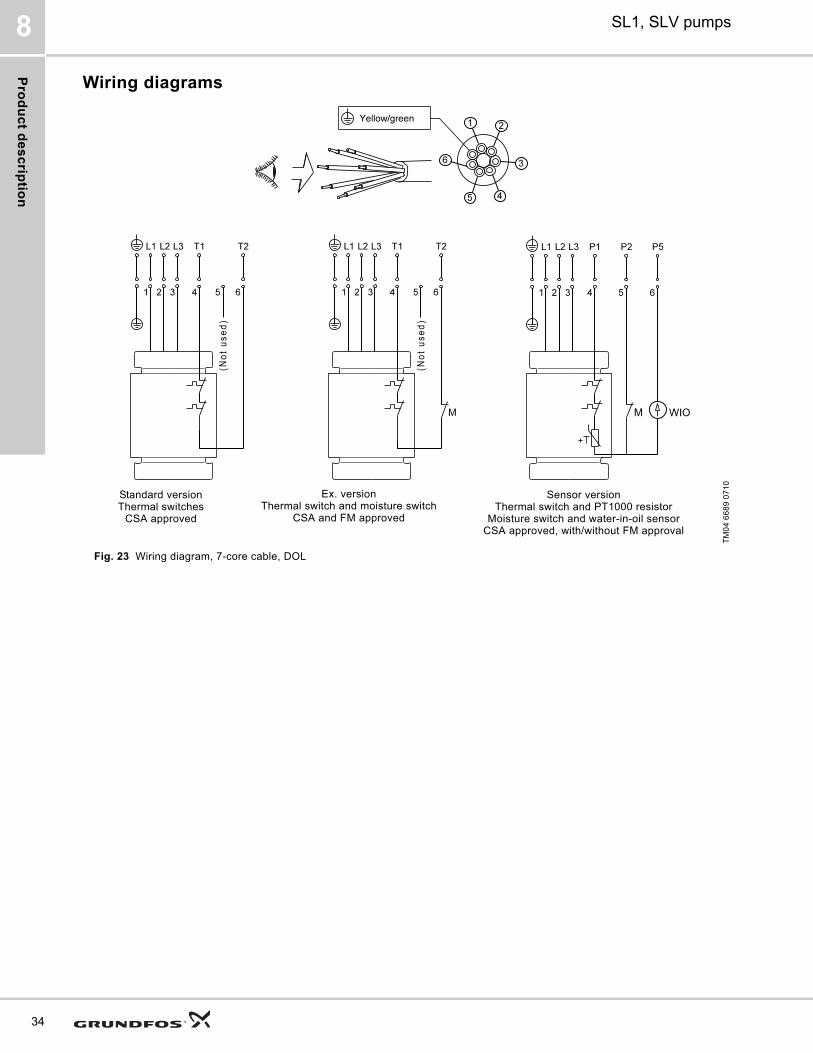
Wiring diagrams
Fig. 23 Wiring diagram, 7-core cable, DOL
TM
04
66
89
07
10
Standard versionThermal switches
CSA approved
Ex. versionThermal switch and moisture switch
CSA and FM approved
Sensor versionThermal switch and PT1000 resistor
Moisture switch and water-in-oil sensorCSA approved, with/without FM approval
Pro
du
ct
de
sc
rip
tio
n
SL1, SLV pumps 8
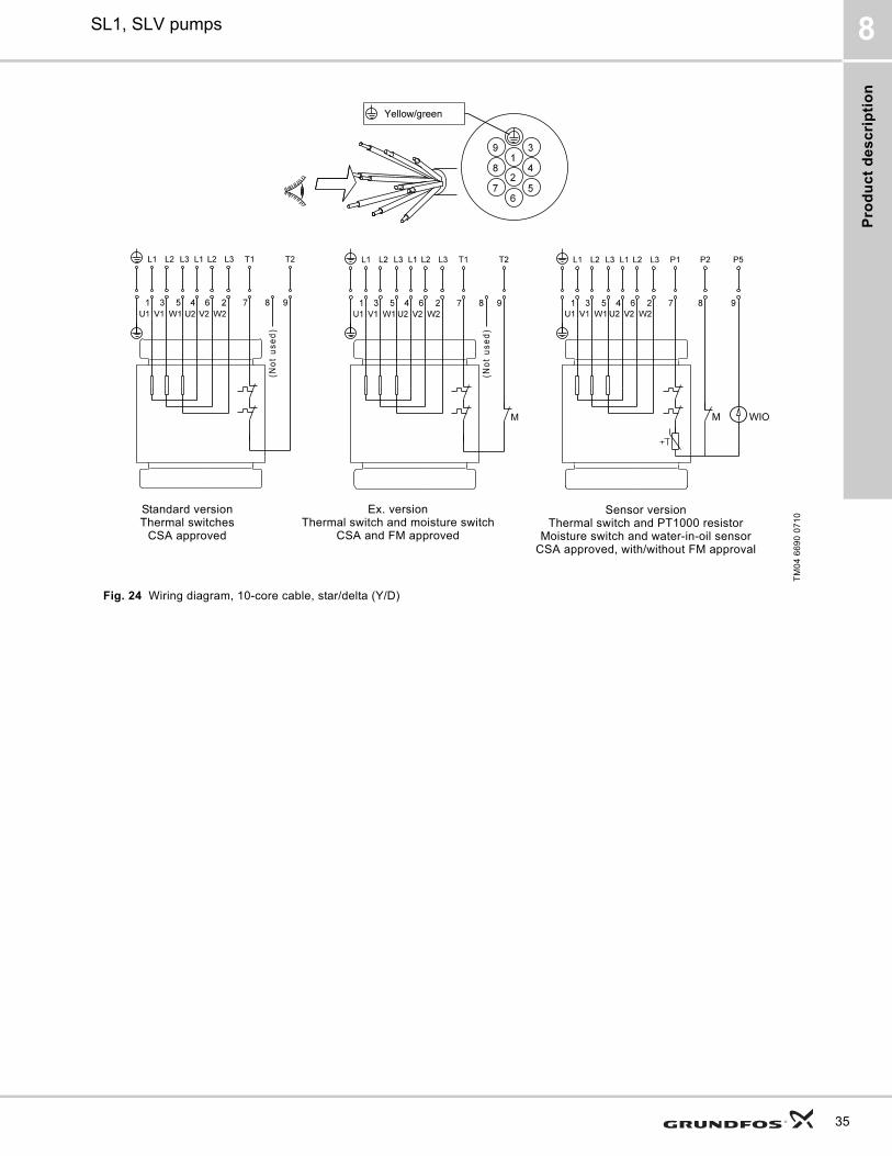
Fig. 24 Wiring diagram, 10-core cable, star/delta (Y/D)
TM
04
66
90
07
10Standard version
Thermal switchesCSA approved
Ex. versionThermal switch and moisture switch
CSA and FM approved
Sensor versionThermal switch and PT1000 resistor
Moisture switch and water-in-oil sensorCSA approved, with/without FM approval
35

Pro
du
ct d
es
crip
tion
SL1, SLV pumps8
36
Fig. 25 Wiring diagram, 10-core cable, star-connected (Y)
TM
04
66
91
07
10
Standard versionThermal switches
CSA approved
Ex. versionThermal switch and moisture switch
CSA and FM approved
Sensor versionThermal switch and PT1000 resistor
Moisture switch and water-in-oil sensorCSA approved, with/without FM approval

Pro
du
ct
de
sc
rip
tio
n
SL1, SLV pumps 8
Fig. 26 Wiring diagram, 10-core cable, delta-connected (D)
TM
04
66
92
07
10
Standard versionThermal switches
CSA approved
Ex. versionThermal switch and moisture switch
CSA and FM approved
Sensor versionThermal switch and PT1000 resistor
Moisture switch and water-in-oil sensorCSA approved, with/without FM approval
37
Cu
rve
ch
arts
an
d te
ch
nic
al d
ata
SL1, SLV pumps9
38
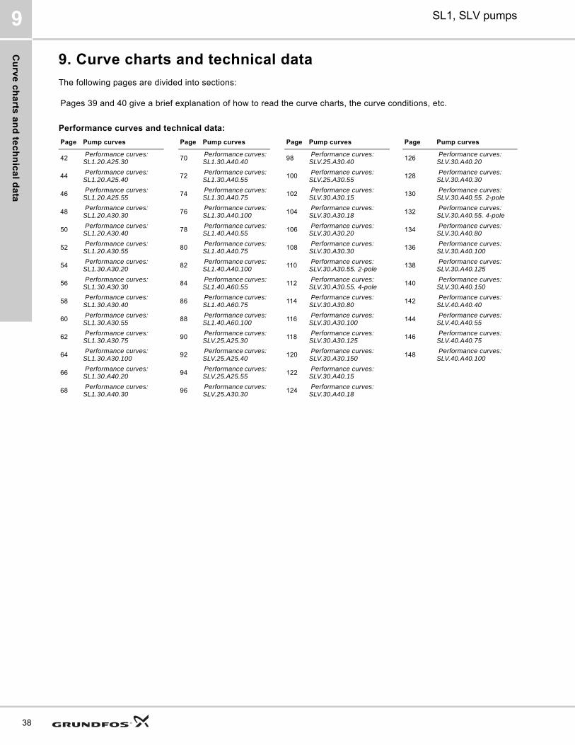
9. Curve charts and technical data
The following pages are divided into sections:
Pages 39 and 40 give a brief explanation of how to read the curve charts, the curve conditions, etc.
Performance curves and technical data:
Page Pump curves Page Pump curves Page Pump curves Page Pump curves
42 Performance curves: SL1.20.A25.30
70 Performance curves: SL1.30.A40.40
98 Performance curves: SLV.25.A30.40
126 Performance curves: SLV.30.A40.20
44 Performance curves: SL1.20.A25.40
72 Performance curves: SL1.30.A40.55
100 Performance curves: SLV.25.A30.55
128 Performance curves: SLV.30.A40.30
46 Performance curves: SL1.20.A25.55
74 Performance curves: SL1.30.A40.75
102 Performance curves: SLV.30.A30.15
130 Performance curves: SLV.30.A40.55. 2-pole
48 Performance curves: SL1.20.A30.30
76 Performance curves: SL1.30.A40.100
104 Performance curves: SLV.30.A30.18
132 Performance curves: SLV.30.A40.55. 4-pole
50 Performance curves: SL1.20.A30.40
78 Performance curves: SL1.40.A40.55
106 Performance curves: SLV.30.A30.20
134 Performance curves: SLV.30.A40.80
52 Performance curves: SL1.20.A30.55
80 Performance curves: SL1.40.A40.75
108 Performance curves: SLV.30.A30.30
136 Performance curves: SLV.30.A40.100
54 Performance curves: SL1.30.A30.20
82 Performance curves: SL1.40.A40.100
110 Performance curves: SLV.30.A30.55. 2-pole
138 Performance curves: SLV.30.A40.125
56 Performance curves: SL1.30.A30.30
84 Performance curves: SL1.40.A60.55
112 Performance curves: SLV.30.A30.55. 4-pole
140 Performance curves: SLV.30.A40.150
58 Performance curves: SL1.30.A30.40
86 Performance curves: SL1.40.A60.75
114 Performance curves: SLV.30.A30.80
142 Performance curves: SLV.40.A40.40
60 Performance curves: SL1.30.A30.55
88 Performance curves: SL1.40.A60.100
116 Performance curves: SLV.30.A30.100
144 Performance curves: SLV.40.A40.55
62 Performance curves: SL1.30.A30.75
90 Performance curves: SLV.25.A25.30
118 Performance curves: SLV.30.A30.125
146 Performance curves: SLV.40.A40.75
64 Performance curves: SL1.30.A30.100
92 Performance curves: SLV.25.A25.40
120 Performance curves: SLV.30.A30.150
148 Performance curves: SLV.40.A40.100
66 Performance curves: SL1.30.A40.20
94 Performance curves: SLV.25.A25.55
122 Performance curves: SLV.30.A40.15
68 Performance curves: SL1.30.A40.30
96 Performance curves: SLV.25.A30.30
124 Performance curves: SLV.30.A40.18
Cu
rve
ch
art
s a
nd
te
ch
nic
al
da
ta
SL1, SLV pumps 9
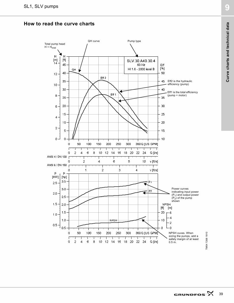
How to read the curve charts
TM
04
72
68
18
10
0 50 100 150 200 250 300 350 Q [US GPM]
0
5
10
15
20
25
30
35
40
45
[ft]H
0 2 4 6 8 10 v [ft/s]
10
15
20
25
30
35
40
45
50
[%]Eff
0 1 2 3 4 v [ft/s]
0 2 4 6 8 10 12 14 16 18 20 22 24 Q [l/s]
0
2
4
6
8
10
12
14[m]H
SLV.30.A40.30.4
60 Hz
HI 1.6 - 2000 level B
Eff 2
Eff 1
QH
ANSI 4 / DN 100
ANSI 6 / DN 150
0 50 100 150 200 250 300 350 Q [US GPM]
0.5
1.0
1.5
2.0
2.5
3.0
3.5
[hp]P
0 2 4 6 8 10 12 14 16 18 20 22 24 Q [l/s]
0
10
20
[ft]NPSH
0.5
1.0
1.5
2.0
2.5
[kW]P
0
2
4
6
[m]
NPSH
P2
P1
Pump typeQH curve
Eff2 is the hydraulic efficiency (pump)
Total pump head H = Htotal
Power curves indicating input power (P1) and output power (P2) of the pump shown
NPSH cuves. When sizing the pumps, add a safety margin of at least 0.5 m.
Eff1 is the total efficiency (pump + motor)
39
Cu
rve
ch
arts
an
d te
ch
nic
al d
ata
SL1, SLV pumps9
40
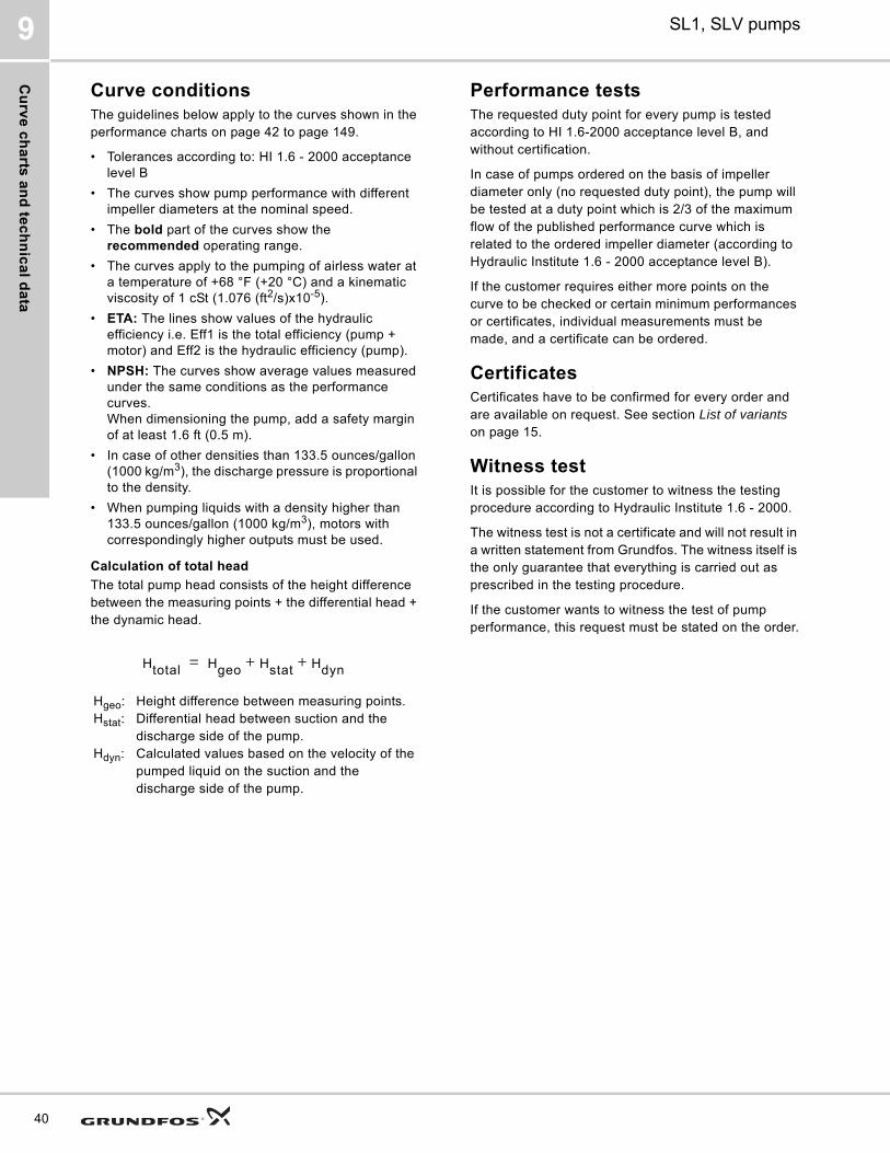
Curve conditionsThe guidelines below apply to the curves shown in the performance charts on page 42 to page 149.
• Tolerances according to: HI 1.6 - 2000 acceptance level B
• The curves show pump performance with different impeller diameters at the nominal speed.
• The bold part of the curves show the recommended operating range.
• The curves apply to the pumping of airless water at a temperature of +68 °F (+20 °C) and a kinematic viscosity of 1 cSt (1.076 (ft2/s)x10-5).
• ETA: The lines show values of the hydraulic efficiency i.e. Eff1 is the total efficiency (pump + motor) and Eff2 is the hydraulic efficiency (pump).
• NPSH: The curves show average values measured under the same conditions as the performance curves.When dimensioning the pump, add a safety margin of at least 1.6 ft (0.5 m).
• In case of other densities than 133.5 ounces/gallon (1000 kg/m3), the discharge pressure is proportional to the density.
• When pumping liquids with a density higher than 133.5 ounces/gallon (1000 kg/m3), motors with correspondingly higher outputs must be used.
Calculation of total head
The total pump head consists of the height difference between the measuring points + the differential head + the dynamic head.
Performance testsThe requested duty point for every pump is tested according to HI 1.6-2000 acceptance level B, and without certification.
In case of pumps ordered on the basis of impeller diameter only (no requested duty point), the pump will be tested at a duty point which is 2/3 of the maximum flow of the published performance curve which is related to the ordered impeller diameter (according to Hydraulic Institute 1.6 - 2000 acceptance level B).
If the customer requires either more points on the curve to be checked or certain minimum performances or certificates, individual measurements must be made, and a certificate can be ordered.
CertificatesCertificates have to be confirmed for every order and are available on request. See section List of variants on page 15.
Witness testIt is possible for the customer to witness the testing procedure according to Hydraulic Institute 1.6 - 2000.
The witness test is not a certificate and will not result in a written statement from Grundfos. The witness itself is the only guarantee that everything is carried out as prescribed in the testing procedure.
If the customer wants to witness the test of pump performance, this request must be stated on the order.
Hgeo: Height difference between measuring points.Hstat: Differential head between suction and the
discharge side of the pump.Hdyn: Calculated values based on the velocity of the
pumped liquid on the suction and the discharge side of the pump.
Htotal Hgeo Hstat Hdyn+ +=
Cu
rve
ch
art
s a
nd
te
ch
nic
al
da
ta
SL1, SLV pumps 9
41
Pe
rform
an
ce
cu
rve
s/te
ch
nic
al d
ata
10
42
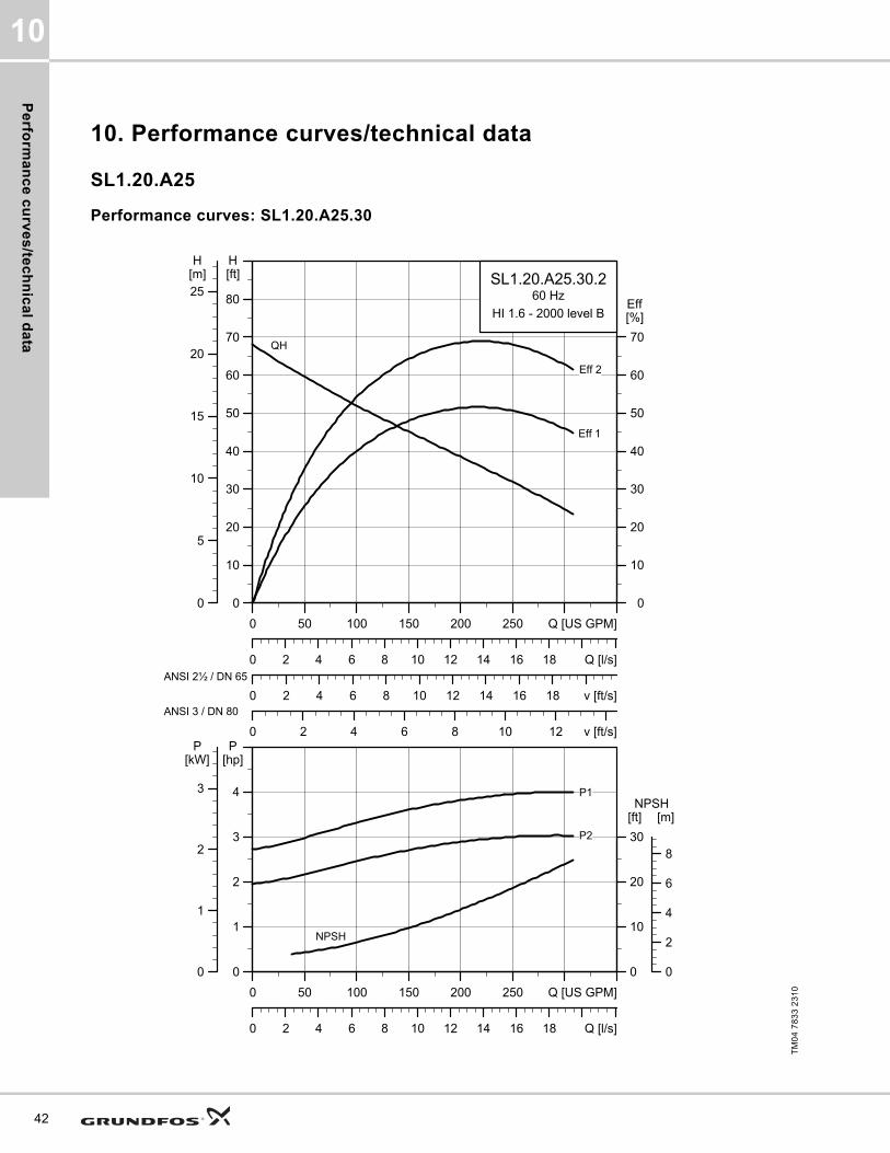
10. Performance curves/technical data
SL1.20.A25
Performance curves: SL1.20.A25.30
TM
04
78
33
23
10
0 50 100 150 200 250 Q [US GPM]
0
10
20
30
40
50
60
70
80
[ft]H
0 2 4 6 8 10 12 14 16 18 v [ft/s]
0
10
20
30
40
50
60
70
[%]Eff
0 2 4 6 8 10 12 v [ft/s]
0 2 4 6 8 10 12 14 16 18 Q [l/s]
0
5
10
15
20
25[m]H
SL1.20.A25.30.260 Hz
HI 1.6 - 2000 level B
Eff 2
Eff 1
QH
ANSI 2½ / DN 65
ANSI 3 / DN 80
0 50 100 150 200 250 Q [US GPM]
0
1
2
3
4
[hp]P
0 2 4 6 8 10 12 14 16 18 Q [l/s]
0
10
20
30
[ft]NPSH
0
1
2
3
[kW]P
0
2
4
6
8
[m]
NPSH
P2
P1
Pe
rfo
rma
nc
e c
urv
es
/te
ch
nic
al
da
ta
10
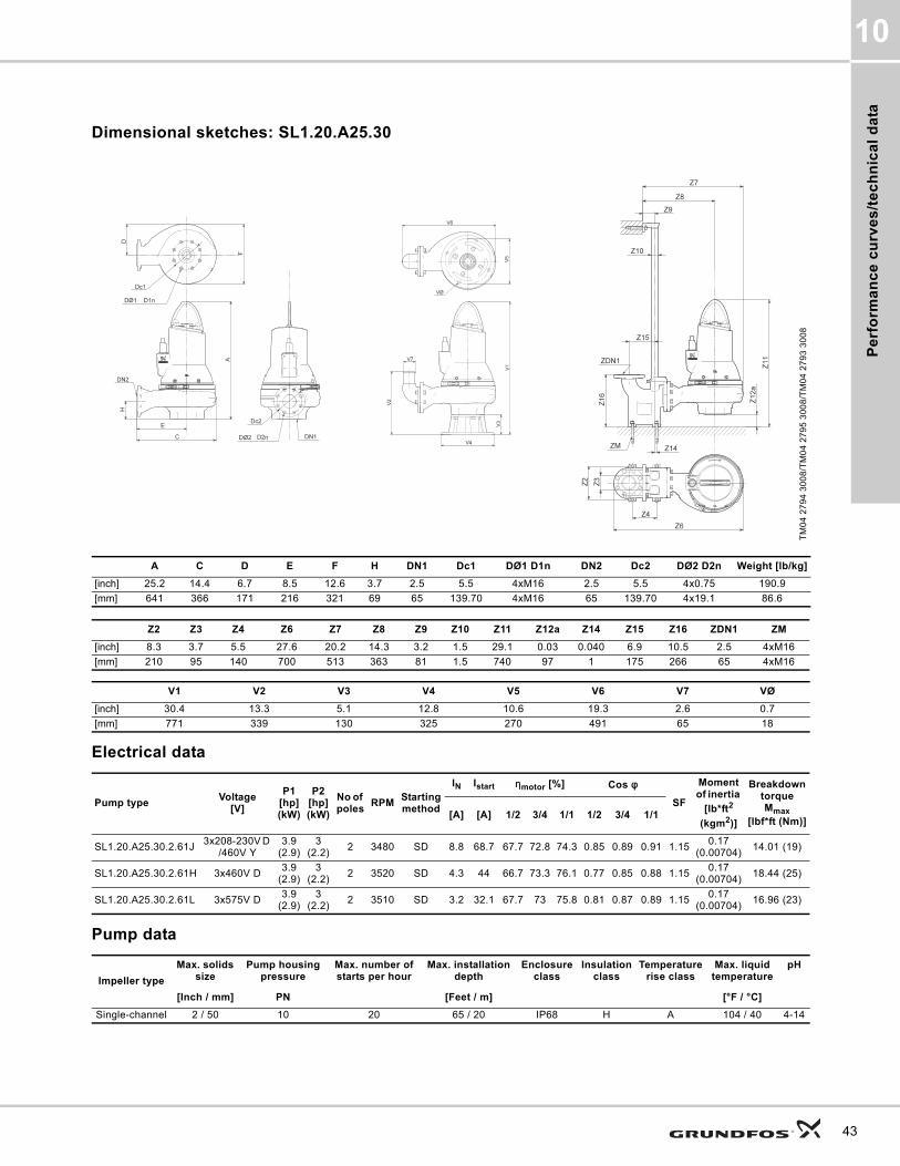
Dimensional sketches: SL1.20.A25.30
Electrical data
Pump data
TM
04
27
94
30
08
/TM
04
27
95
30
08
/TM
04
27
93
30
08
A C D E F H DN1 Dc1 DØ1 D1n DN2 Dc2 DØ2 D2n Weight [lb/kg]
[inch] 25.2 14.4 6.7 8.5 12.6 3.7 2.5 5.5 4xM16 2.5 5.5 4x0.75 190.9
[mm] 641 366 171 216 321 69 65 139.70 4xM16 65 139.70 4x19.1 86.6
Z2 Z3 Z4 Z6 Z7 Z8 Z9 Z10 Z11 Z12a Z14 Z15 Z16 ZDN1 ZM
[inch] 8.3 3.7 5.5 27.6 20.2 14.3 3.2 1.5 29.1 0.03 0.040 6.9 10.5 2.5 4xM16
[mm] 210 95 140 700 513 363 81 1.5 740 97 1 175 266 65 4xM16
V1 V2 V3 V4 V5 V6 V7 VØ
[inch] 30.4 13.3 5.1 12.8 10.6 19.3 2.6 0.7
[mm] 771 339 130 325 270 491 65 18
Pump typeVoltage
[V]
P1 [hp] (kW)
P2 [hp] (kW)
No of poles
RPMStarting method
IN Istart ηmotor [%] Cos φ
SF
Moment of inertia
[lb*ft2
(kgm2)]
Breakdown torque Mmax
[lbf*ft (Nm)][A] [A] 1/2 3/4 1/1 1/2 3/4 1/1
SL1.20.A25.30.2.61J3x208-230V D
/460V Y3.9
(2.9)3
(2.2)2 3480 SD 8.8 68.7 67.7 72.8 74.3 0.85 0.89 0.91 1.15
0.17 (0.00704)
14.01 (19)
SL1.20.A25.30.2.61H 3x460V D3.9
(2.9)3
(2.2)2 3520 SD 4.3 44 66.7 73.3 76.1 0.77 0.85 0.88 1.15
0.17 (0.00704)
18.44 (25)
SL1.20.A25.30.2.61L 3x575V D3.9
(2.9)3
(2.2)2 3510 SD 3.2 32.1 67.7 73 75.8 0.81 0.87 0.89 1.15
0.17 (0.00704)
16.96 (23)
Impeller type
Max. solids size
Pump housing pressure
Max. number of starts per hour
Max. installation depth
Enclosure class
Insulation class
Temperature rise class
Max. liquid temperature
pH
[Inch / mm] PN [Feet / m] [°F / °C]
Single-channel 2 / 50 10 20 65 / 20 IP68 H A 104 / 40 4-14
43
Pe
rform
an
ce
cu
rve
s/te
ch
nic
al d
ata
10
44
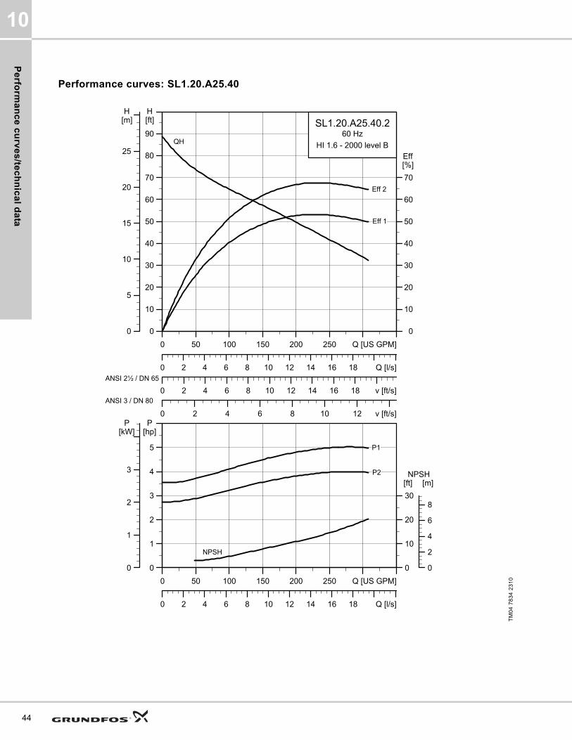
Performance curves: SL1.20.A25.40
TM
04
78
34
23
10
0 50 100 150 200 250 Q [US GPM]
0
10
20
30
40
50
60
70
80
90
[ft]H
0 2 4 6 8 10 12 14 16 18 v [ft/s]
0
10
20
30
40
50
60
70
[%]Eff
0 2 4 6 8 10 12 v [ft/s]
0 2 4 6 8 10 12 14 16 18 Q [l/s]
0
5
10
15
20
25
[m]H
SL1.20.A25.40.260 Hz
HI 1.6 - 2000 level B
Eff 2
Eff 1
QH
ANSI 2½ / DN 65
ANSI 3 / DN 80
0 50 100 150 200 250 Q [US GPM]
0
1
2
3
4
5
[hp]P
0 2 4 6 8 10 12 14 16 18 Q [l/s]
0
10
20
30
[ft]NPSH
0
1
2
3
[kW]P
0
2
4
6
8
[m]
NPSH
P2
P1

Pe
rfo
rma
nc
e c
urv
es
/te
ch
nic
al
da
ta
10
Dimensional sketches: SL1.20.A25.40
Electrical data
Pump data
TM
04
27
94
30
08
/TM
04
27
95
30
08
/TM
04
27
93
30
08
A C D E F H DN1 Dc1 DØ1 D1n DN2 Dc2 DØ2 D2n Weight [lb/kg]
[inch] 25.2 14.4 6.7 8.5 12.6 3.7 2.5 5.5 4xM16 2.5 5.5 4x0.75 197.8
[mm] 641 366 171 216 321 69 65 139.70 4xM16 65 139.70 4x19.1 89.7
Z2 Z3 Z4 Z6 Z7 Z8 Z9 Z10 Z11 Z12a Z14 Z15 Z16 ZDN1 ZM
[inch] 8.3 3.7 5.5 27.6 20.2 14.3 3.2 1.5 29.1 0.03 0.040 6.9 10.5 2.5 4xM16
[mm] 210 95 140 700 513 363 81 1.5 740 97 1 175 266 65 4xM16
V1 V2 V3 V4 V5 V6 V7 VØ
[inch] 30.4 13.3 5.1 12.8 10.6 19.3 2.6 0.7
[mm] 771 339 130 325 270 491 65 18
Pump typeVoltage
[V]
P1 [hp] (kW)
P2 [hp] (kW)
No of poles
RPMStarting method
IN Istart ηmotor [%] Cos ϕ
SF
Moment of inertia
[lb*ft2
(kgm2)]
Breakdown torque Mmax
[lbf*ft (Nm)][A] [A] 1/2 3/4 1/1 1/2 3/4 1/1
SL1.20.A25.40.2.61J3x208-230V D
/460V Y5.1
(3.8)4 (3) 2 3510 SD 11.6 99.5 72.9 77.2 78.4 0.79 0.86 0.89 1.15
0.23 (0.00956)
22.86 (31)
SL1.20.A25.40.2.61L 3x575V D5.1
(3.8)4 (3) 2 3510 SD 4.5 47.9 72.9 77.8 79.6 0.74 0.82 0.87 1.15
0.23 (0.00956)
28.03 (38)
SL1.20.A25.40.2.61H 3x460V D5.1
(3.8)4 (3) 2 3510 SD 5.9 63.5 72.5 77.4 79.7 0.66 0.77 0.83 1.15
0.23 (0.00956)
29.5 (40)
Impeller type
Max. solids size
Pump housing pressure
Max. number of starts per hour
Max. installation depth
Enclosure class
Insulation class
Temperature rise class
Max. liquid temperature
pH
[Inch / mm] PN [Feet / m] [°F / °C]
Single-channel 2 / 50 10 20 65 / 20 IP68 H A 104 / 40 4-14
45

Pe
rform
an
ce
cu
rve
s/te
ch
nic
al d
ata
10
46
Performance curves: SL1.20.A25.55
TM
04
78
35
23
10
0 50 100 150 200 250 Q [US GPM]
0
10
20
30
40
50
60
70
80
90
100
[ft]H
0 2 4 6 8 10 12 14 16 18 v [ft/s]
0
10
20
30
40
50
60
70
[%]Eff
0 2 4 6 8 10 12 v [ft/s]
0 2 4 6 8 10 12 14 16 18 Q [l/s]
0
5
10
15
20
25
30
[m]H
SL1.20.A25.55.260 Hz
HI 1.6 - 2000 level B
Eff 2
Eff 1
QH
ANSI 2½ / DN 65
ANSI 3 / DN 80
0 50 100 150 200 250 Q [US GPM]
2
3
4
5
6
7
[hp]P
0 2 4 6 8 10 12 14 16 18 Q [l/s]
0
10
20
30
[ft]NPSH
2
3
4
5
[kW]P
0
2
4
6
8
[m]
NPSH
P2
P1

Pe
rfo
rma
nc
e c
urv
es
/te
ch
nic
al
da
ta
10
Dimensional sketches: SL1.20.A25.55
Electrical data
Pump data
TM
04
27
94
30
08
/TM
04
27
95
30
08
/TM
04
27
93
30
08
A C D E F H DN1 Dc1 DØ1 D1n DN2 Dc2 DØ2 D2n Weight [lb/kg]
[inch] 26.7 16 7.9 8.9 14.9 3.7 2.5 5.5 4xM16 2.5 5.5 4x0.75 254.9
[mm] 677 407 200 227 379 69 65 139.70 4xM16 65 139.70 4x19.1 115.6
Z2 Z3 Z4 Z6 Z7 Z8 Z9 Z10 Z11 Z12a Z14 Z15 Z16 ZDN1 ZM
[inch] 8.3 3.7 5.5 29.2 21.8 14.8 3.2 1.5 30.5 0.03 0.040 6.9 10.5 2.5 4xM16
[mm] 210 95 140 741 554 375 81 1.5 774 97 1 175 266 65 4xM16
V1 V2 V3 V4 V5 V6 V7 VØ
[inch] 31.8 13.4 5.1 12.8 10.6 20.4 2.6 0.7
[mm] 807 341 130 325 270 519 65 18
Pump typeVoltage
[V]
P1 [hp] (kW)
P2 [hp] (kW)
No of poles
RPMStarting method
IN Istart ηmotor [%] Cos ϕ
SF
Moment of inertia
[lb*ft2
(kgm2)]
Breakdown torque Mmax
[lbf*ft (Nm)][A] [A] 1/2 3/4 1/1 1/2 3/4 1/1
SL1.20.A25.55.2.61J3x208-230V D
/460V Y6.6
(4.9)5.5 (4)
2 3530 SD 14.8 152 75 79.9 81.7 0.78 0.86 0.90 1.150.38
(0.0159)53.51
(72.55)
SL1.20.A25.55.2.61L 3x575V D6.6
(4.9)5.5 (4)
2 3535 SD 5.8 70.8 74.1 79.6 82 0.71 0.82 0.87 1.150.38
(0.0159)44.99 (61)
SL1.20.A25.55.2.61H 3x460V D6.6
(4.9)5.5 (4)
2 3540 SD 7.4 96.8 73.6 79.2 82 0.68 0.80 0.85 1.150.38
(0.0159)37.62 (51)
Impeller type
Max. solids size
Pump housing pressure
Max. number of starts per hour
Max. installation depth
Enclosure class
Insulation class
Temperature rise class
Max. liquid temperature
pH
[Inch / mm] PN [Feet / m] [°F / °C]
Single-channel 2 / 50 10 20 65 / 20 IP68 H A 104 / 40 4-14
47

Pe
rform
an
ce
cu
rve
s/te
ch
nic
al d
ata
10
48
SL1.20.A30
Performance curves: SL1.20.A30.30
TM
04
78
36
23
10
0 50 100 150 200 250 Q [US GPM]
0
10
20
30
40
50
60
70
80
[ft]H
0 2 4 6 8 10 12 v [ft/s]
0
10
20
30
40
50
60
70
[%]Eff
0 2 4 6 8 v [ft/s]
0 2 4 6 8 10 12 14 16 18 Q [l/s]
0
5
10
15
20
25[m]H
SL1.20.A30.30.260 Hz
HI 1.6 - 2000 level B
Eff 2
Eff 1
QH
ANSI 3 / DN 80
ANSI 4 / DN 100
0 50 100 150 200 250 Q [US GPM]
0
1
2
3
4
[hp]P
0 2 4 6 8 10 12 14 16 18 Q [l/s]
0
10
20
30
[ft]NPSH
0
1
2
3
[kW]P
0
2
4
6
8
[m]
NPSH
P1
P2

Pe
rfo
rma
nc
e c
urv
es
/te
ch
nic
al
da
ta
10
Dimensional sketches: SL1.20.A30.30
Electrical data
Pump data
TM
04
27
93
30
08
/TM
04
27
94
30
08
/TM
04
27
95
30
08
A C D E F H DN1 Dc1 DØ1 D1n DN2 Dc2 DØ2 D2n Weight [lb/kg]
[inch] 25.2 14.4 6.7 8.5 12.6 3.9 2.5 5.5 4xM16 3 6 8x0.75 192.7
[mm] 641 366 171 216 321 69 65 139.70 4xM16 80 152.4 8x19.1 87.4
Z2 Z3 Z4 Z6 Z7 Z8 Z9 Z10 Z11 Z12a Z14 Z15 Z16 ZDN1 ZM
[inch] 8.7 3.7 6.3 28.3 20.7 14.8 3.2 1.5 30.5 0.03 0.510 6.7 13.6 3 4xM16
[mm] 220 95 160 719 526 376 81 1.5 774 131 13 171 345 80 4xM16
V1 V2 V3 V4 V5 V6 V7 VØ
[inch] 30.4 13.3 5.1 12.8 10.6 19.5 3.2 0.7
[mm] 771 339 130 325 270 496 80 18
Pump typeVoltage
[V]
P1 [hp] (kW)
P2 [hp] (kW)
No of poles
RPMStarting method
IN Istart ηmotor [%] Cos ϕ
SF
Moment of inertia
[lb*ft2
(kgm2)]
Breakdown torque Mmax
[lbf*ft (Nm)][A] [A] 1/2 3/4 1/1 1/2 3/4 1/1
SL1.20.A30.30.2.61J3x208-230V D
/460V Y3.9
(2.9)3
(2.2)2 3480 SD 8.8 68.7 67.7 72.8 74.3 0.85 0.89 0.91 1.15
0.17 (0.00704)
14.01 (19)
SL1.20.A30.30.2.61H 3x460V D3.9
(2.9)3
(2.2)2 3520 SD 4.3 44 66.7 73.3 76.1 0.77 0.85 0.88 1.15
0.17 (0.00704)
18.44 (25)
SL1.20.A30.30.2.61L 3x575V D3.9
(2.9)3
(2.2)2 3510 SD 3.2 32.1 67.7 73 75.8 0.81 0.87 0.89 1.15
0.17 (0.00704)
16.96 (23)
Impeller type
Max. solids size
Pump housing pressure
Max. number of starts per hour
Max. installation depth
Enclosure class
Insulation class
Temperature rise class
Max. liquid temperature
pH
[Inch / mm] PN [Feet / m] [°F / °C]
Single-channel 2 / 50 10 20 65 / 20 IP68 H A 104 / 40 4-14
49

Pe
rform
an
ce
cu
rve
s/te
ch
nic
al d
ata
10
50
Performance curves: SL1.20.A30.40
TM
04
78
37
23
10
0 50 100 150 200 250 Q [US GPM]
0
10
20
30
40
50
60
70
80
90
[ft]H
0 2 4 6 8 10 12 v [ft/s]
0
10
20
30
40
50
60
70
[%]Eff
0 2 4 6 8 v [ft/s]
0 2 4 6 8 10 12 14 16 18 Q [l/s]
0
5
10
15
20
25
[m]H
SL1.20.A30.40.260 Hz
HI 1.6 - 2000 level B
Eff 1
Eff 2
QH
ANSI 3 / DN 80
ANSI 4 / DN 100
0 50 100 150 200 250 Q [US GPM]
0
1
2
3
4
5
[hp]P
0 2 4 6 8 10 12 14 16 18 Q [l/s]
0
10
20
30
[ft]NPSH
0
1
2
3
[kW]P
0
2
4
6
8
[m]
NPSH
P2
P1

Pe
rfo
rma
nc
e c
urv
es
/te
ch
nic
al
da
ta
10
Dimensional sketches: SL1.20.A30.40
Electrical data
Pump data
TM
04
27
93
30
08
/TM
04
27
94
30
08
/TM
04
27
95
30
08
A C D E F H DN1 Dc1 DØ1 D1n DN2 Dc2 DØ2 D2n Weight [lb/kg]
[inch] 25.2 14.4 6.7 8.5 12.6 3.9 2.5 5.5 4xM16 3 6 8x0.75 199.5
[mm] 641 366 171 216 321 69 65 139.70 4xM16 80 152.4 8x19.1 90.5
Z2 Z3 Z4 Z6 Z7 Z8 Z9 Z10 Z11 Z12a Z14 Z15 Z16 ZDN1 ZM
[inch] 8.7 3.7 6.3 28.3 20.7 14.8 3.2 1.5 30.5 0.03 0.510 6.7 13.6 3 4xM16
[mm] 220 95 160 719 526 376 81 1.5 774 131 13 171 345 80 4xM16
V1 V2 V3 V4 V5 V6 V7 VØ
[inch] 30.4 13.3 5.1 12.8 10.6 19.5 3.2 0.7
[mm] 771 339 130 325 270 496 80 18
Pump typeVoltage
[V]
P1 [hp] (kW)
P2 [hp] (kW)
No of poles
RPMStarting method
IN Istart ηmotor [%] Cos ϕ
SF
Moment of inertia
[lb*ft2
(kgm2)]
Breakdown torque Mmax
[lbf*ft (Nm)][A] [A] 1/2 3/4 1/1 1/2 3/4 1/1
SL1.20.A30.40.2.61J3x208-230V D
/460V Y5.1
(3.8)4 (3) 2 3510 SD 11.6 99.5 72.9 77.2 78.4 0.79 0.86 0.89 1.15
0.23 (0.00956)
22.86 (31)
SL1.20.A30.40.2.61L 3x575V D5.1
(3.8)4 (3) 2 3510 SD 4.5 47.9 72.9 77.8 79.6 0.74 0.82 0.87 1.15
0.23 (0.00956)
28.03 (38)
SL1.20.A30.40.2.61H 3x460V D5.1
(3.8)4 (3) 2 3510 SD 5.9 63.5 72.5 77.4 79.7 0.66 0.77 0.83 1.15
0.23 (0.00956)
29.5 (40)
Impeller type
Max. solids size
Pump housing pressure
Max. number of starts per hour
Max. installation depth
Enclosure class
Insulation class
Temperature rise class
Max. liquid temperature
pH
[Inch / mm] PN [Feet / m] [°F / °C]
Single-channel 2 / 50 10 20 65 / 20 IP68 H A 104 / 40 4-14
51
Pe
rform
an
ce
cu
rve
s/te
ch
nic
al d
ata
10
52
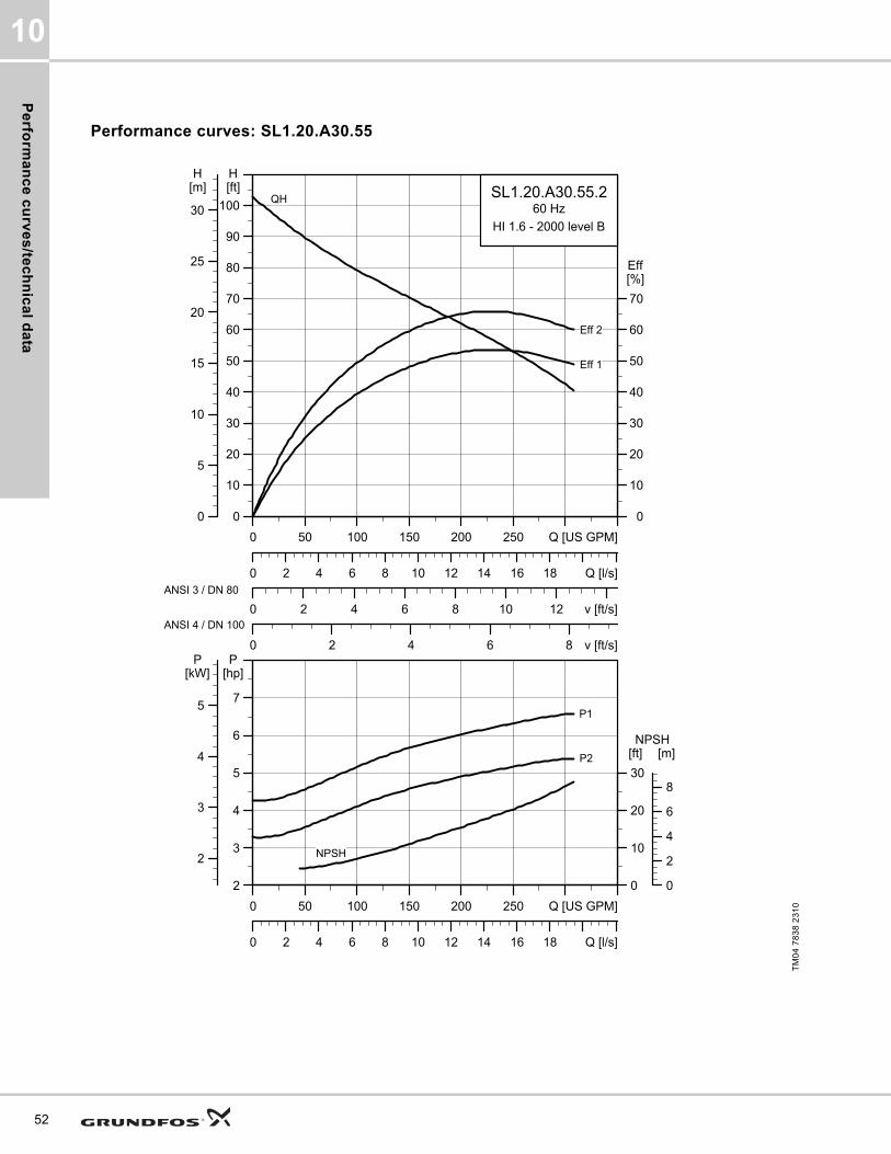
Performance curves: SL1.20.A30.55
TM
04
78
38
23
10
0 50 100 150 200 250 Q [US GPM]
0
10
20
30
40
50
60
70
80
90
100
[ft]H
0 2 4 6 8 10 12 v [ft/s]
0
10
20
30
40
50
60
70
[%]Eff
0 2 4 6 8 v [ft/s]
0 2 4 6 8 10 12 14 16 18 Q [l/s]
0
5
10
15
20
25
30
[m]H
SL1.20.A30.55.260 Hz
HI 1.6 - 2000 level B
Eff 2
Eff 1
QH
ANSI 3 / DN 80
ANSI 4 / DN 100
0 50 100 150 200 250 Q [US GPM]
2
3
4
5
6
7
[hp]P
0 2 4 6 8 10 12 14 16 18 Q [l/s]
0
10
20
30
[ft]NPSH
2
3
4
5
[kW]P
0
2
4
6
8
[m]
NPSH
P2
P1

Pe
rfo
rma
nc
e c
urv
es
/te
ch
nic
al
da
ta
10
Dimensional sketches: SL1.20.A30.55
Electrical data
Pump data
TM
04
27
93
30
08
/TM
04
27
94
30
08
/TM
04
27
95
30
08
A C D E F H DN1 Dc1 DØ1 D1n DN2 Dc2 DØ2 D2n Weight [lb/kg]
[inch] 26.7 16 7.9 8.9 14.9 3.9 2.5 5.5 4xM16 3 6 8x0.75 256.6
[mm] 677 407 200 227 379 69 65 139.70 4xM16 80 152.4 8x19.1 116.4
Z2 Z3 Z4 Z6 Z7 Z8 Z9 Z10 Z11 Z12a Z14 Z15 Z16 ZDN1 ZM
[inch] 8.7 3.7 6.3 29.9 22.3 15.2 3.2 1.5 31.8 0.03 0.510 6.7 13.6 3 4xM16
[mm] 220 95 160 760 567 387 81 1.5 808 131 13 171 345 80 4xM16
V1 V2 V3 V4 V5 V6 V7 VØ
[inch] 31.8 13.4 5.1 12.8 10.6 20.7 3.2 0.7
[mm] 807 341 130 325 270 525 80 18
Pump typeVoltage
[V]
P1 [hp] (kW)
P2 [hp] (kW)
No of poles
RPMStarting method
IN Istart ηmotor [%] Cos ϕ
SF
Moment of inertia
[lb*ft2
(kgm2)]
Breakdown torque Mmax
[lbf*ft (Nm)][A] [A] 1/2 3/4 1/1 1/2 3/4 1/1
SL1.20.A30.55.2.61J3x208-230V D
/460V Y6.6
(4.9)5.5 (4)
2 3530 SD 14.8 152 75 79.9 81.7 0.78 0.86 0.90 1.150.38
(0.0159)53.51 (72.5)
SL1.20.A30.55.2.61L 3x575V D6.6
(4.9)5.5 (4)
2 3535 SD 5.8 70.8 74.1 79.6 82 0.71 0.82 0.87 1.150.38
(0.0159)44.99 (61)
SL1.20.A30.55.2.61H 3x460V D6.6
(4.9)5.5 (4)
2 3540 SD 7.4 96.8 73.6 79.2 82 0.68 0.80 0.85 1.150.38
(0.0159)37.62 (51)
Impeller type
Max. solids size
Pump housing pressure
Max. number of starts per hour
Max. installation depth
Enclosure class
Insulation class
Temperature rise class
Max. liquid temperature
pH
[Inch / mm] PN [Feet / m] [°F / °C]
Single-channel 2 / 50 10 20 65 / 20 IP68 H A 104 / 40 4-14
53
Pe
rform
an
ce
cu
rve
s/te
ch
nic
al d
ata
10
54
SL1.30.A30
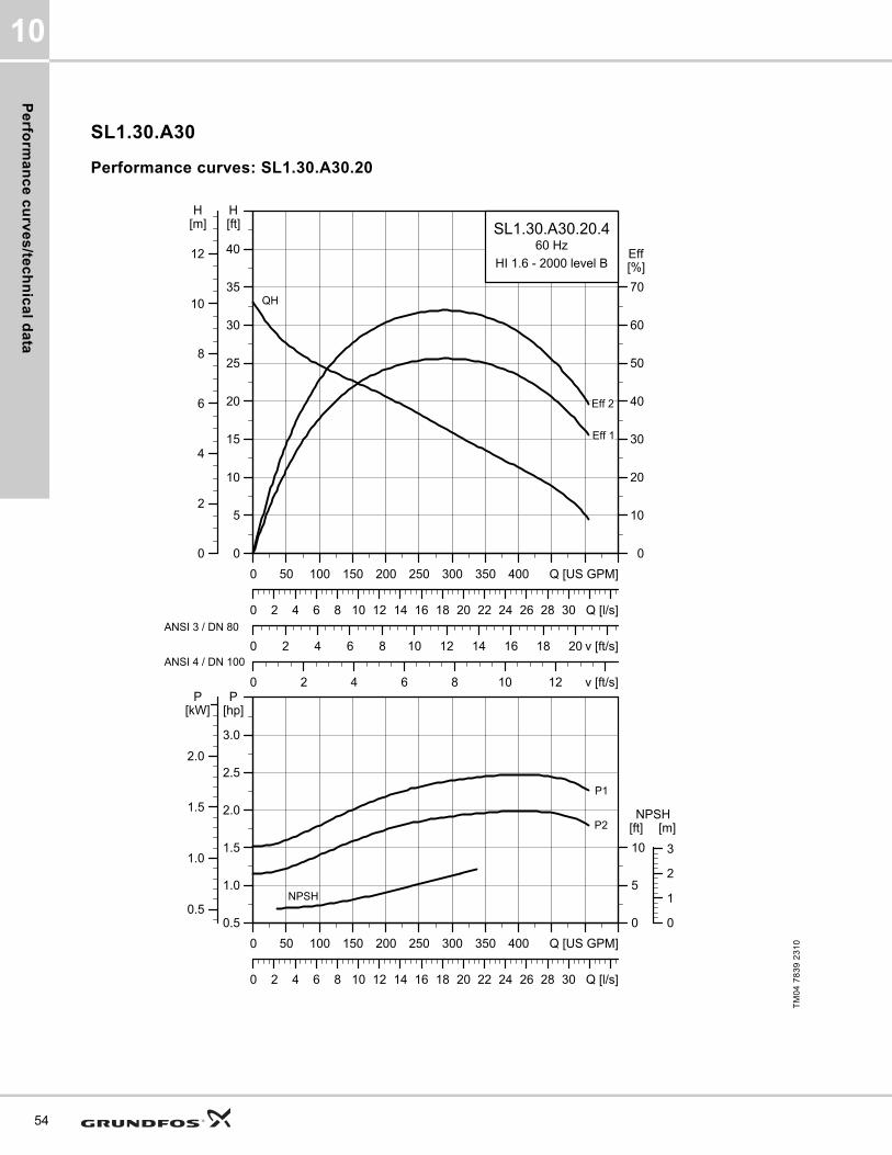
Performance curves: SL1.30.A30.20
TM
04
78
39
23
10
0 50 100 150 200 250 300 350 400 Q [US GPM]
0
5
10
15
20
25
30
35
40
[ft]H
0 2 4 6 8 10 12 14 16 18 20 v [ft/s]
0
10
20
30
40
50
60
70
[%]Eff
0 2 4 6 8 10 12 v [ft/s]
0 2 4 6 8 10 12 14 16 18 20 22 24 26 28 30 Q [l/s]
0
2
4
6
8
10
12
[m]H
SL1.30.A30.20.460 Hz
HI 1.6 - 2000 level B
QH
Eff 1
Eff 2
ANSI 3 / DN 80
ANSI 4 / DN 100
0 50 100 150 200 250 300 350 400 Q [US GPM]
0.5
1.0
1.5
2.0
2.5
3.0
[hp]P
0 2 4 6 8 10 12 14 16 18 20 22 24 26 28 30 Q [l/s]
0
5
10
[ft]NPSH
0.5
1.0
1.5
2.0
[kW]P
0
1
2
3
[m]
P1
P2
NPSH

Pe
rfo
rma
nc
e c
urv
es
/te
ch
nic
al
da
ta
10
Dimensional sketches: SL1.30.A30.20
Electrical data
Pump data
TM
04
27
93
30
08
/TM
04
27
94
30
08
/TM
04
27
95
30
08
A C D E F H DN1 Dc1 DØ1 D1n DN2 Dc2 DØ2 D2n Weight [lb/kg]
[inch] 26.9 17.1 6.7 10.7 14.7 3.9 4 7.5 8xM16 3 6 8x0.75 212.1
[mm] 682 435 171 272 374 89 100 190.5 8xM16 80 152.4 8x19.1 96.2
Z2 Z3 Z4 Z6 Z7 Z8 Z9 Z10 Z11 Z12a Z14 Z15 Z16 ZDN1 ZM
[inch] 8.7 3.7 6.3 31 23.4 17 3.2 1.5 31.1 0.03 0.510 6.7 13.6 3 4xM16
[mm] 220 95 160 788 595 432 81 1.5 790 111 13 171 345 80 4xM16
V1 V2 V3 V4 V5 V6 V7 VØ
[inch] 32 14.3 5.1 14 11.8 22.3 3.2 0.7
[mm] 812 364 130 355 300 567 80 19
Pump typeVoltage
[V]
P1 [hp] (kW)
P2 [hp] (kW)
No of poles
RPMStarting method
IN Istart ηmotor [%] Cos ϕ
SF
Moment of inertia
[lb*ft2
(kgm2)]
Breakdown torque Mmax
[lbf*ft (Nm)][A] [A] 1/2 3/4 1/1 1/2 3/4 1/1
SL1.30.A30.20.4.60J3x208-230V D
/460V Y2.5
(1.9)2
(1.5)4 1750 DOL 6.6 42.5 69.6 74.4 76.2 0.65 0.74 0.80 1.15
0.67 (0.0284)
19.18 (26)
SL1.30.A30.20.4.60L 3x575V D2.5
(1.9)2
(1.5)4 1750 DOL 2.6 20 68.7 74.4 77 0.59 0.69 0.76 1.15
0.67 (0.0284)
22.86 (31)
SL1.30.A30.20.4.61L 3x575V D2.5
(1.9)2
(1.5)4 1750 SD 2.6 20 68.7 74.4 77 0.59 0.69 0.76 1.15
0.67 (0.0284)
22.86 (31)
SL1.30.A30.20.4.61J3x208-230V D
/460V Y2.5
(1.9)2
(1.5)4 1750 SD 6.6 42.5 69.6 74.4 76.2 0.65 0.74 0.80 1.15
0.67 (0.0284)
19.18 (26)
Impeller type
Max. solids size
Pump housing pressure
Max. number of starts per hour
Max. installation depth
Enclosure class
Insulation class
Temperature rise class
Max. liquid temperature
pH
[Inch / mm] PN [Feet / m] [°F / °C]
Single-channel 3 / 80 10 20 65 / 20 IP68 H A 104 / 40 4-14
55
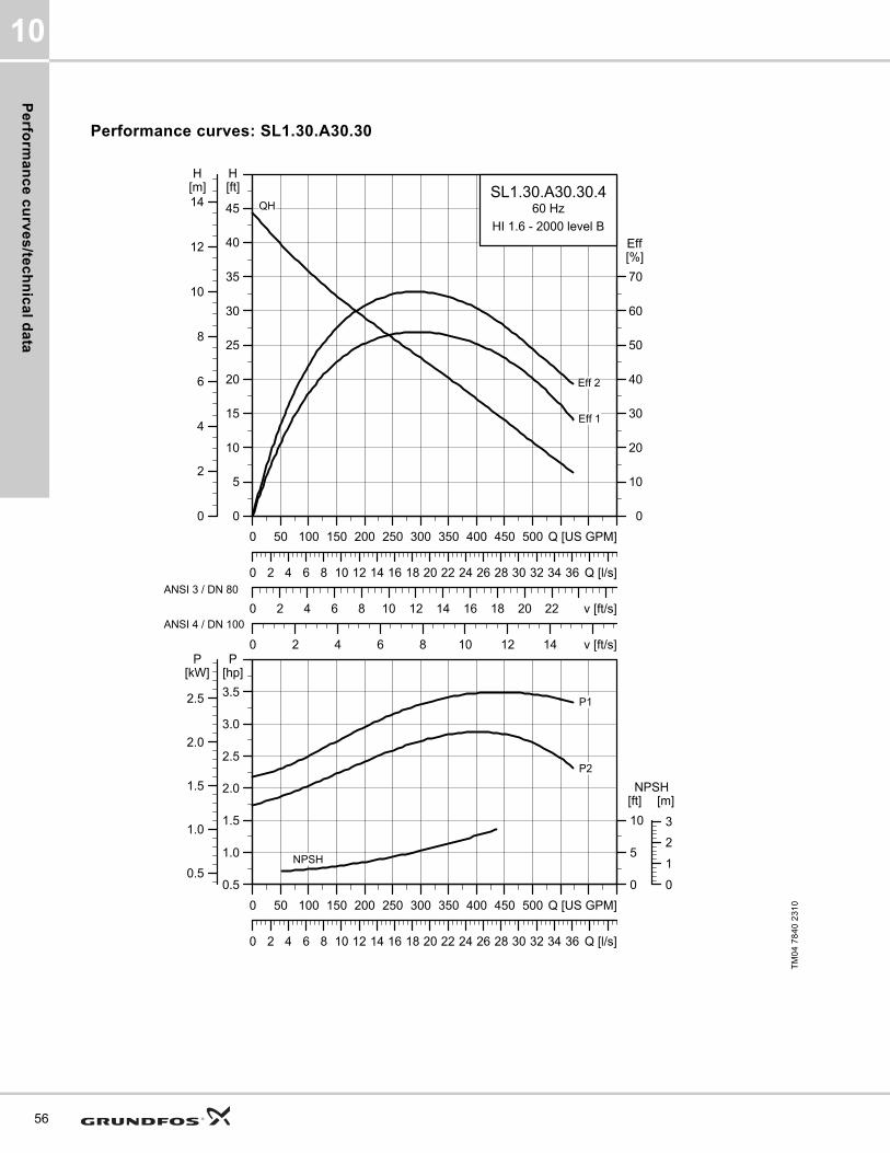
Pe
rform
an
ce
cu
rve
s/te
ch
nic
al d
ata
10
56
Performance curves: SL1.30.A30.30
TM
04
78
40
23
10
0 50 100 150 200 250 300 350 400 450 500 Q [US GPM]
0
5
10
15
20
25
30
35
40
45
[ft]H
0 2 4 6 8 10 12 14 16 18 20 22 v [ft/s]
0
10
20
30
40
50
60
70
[%]Eff
0 2 4 6 8 10 12 14 v [ft/s]
0 2 4 6 8 10 12 14 16 18 20 22 24 26 28 30 32 34 36 Q [l/s]
0
2
4
6
8
10
12
14[m]H
SL1.30.A30.30.460 Hz
HI 1.6 - 2000 level B
Eff 2
Eff 1
QH
ANSI 3 / DN 80
ANSI 4 / DN 100
0 50 100 150 200 250 300 350 400 450 500 Q [US GPM]
0.5
1.0
1.5
2.0
2.5
3.0
3.5
[hp]P
0 2 4 6 8 10 12 14 16 18 20 22 24 26 28 30 32 34 36 Q [l/s]
0
5
10
[ft]NPSH
0.5
1.0
1.5
2.0
2.5
[kW]P
0
1
2
3
[m]
NPSH
P2
P1

Pe
rfo
rma
nc
e c
urv
es
/te
ch
nic
al
da
ta
10
Dimensional sketches: SL1.30.A30.30
Electrical data
Pump data
TM
04
27
93
30
08
/TM
04
27
94
30
08
/TM
04
27
95
30
08
A C D E F H DN1 Dc1 DØ1 D1n DN2 Dc2 DØ2 D2n Weight [lb/kg]
[inch] 26.9 17.1 6.7 10.7 14.7 3.9 4 7.5 8xM16 3 6 8x0.75 242.5
[mm] 682 435 171 272 374 89 100 190.5 8xM16 80 152.4 8x19.1 110
Z2 Z3 Z4 Z6 Z7 Z8 Z9 Z10 Z11 Z12a Z14 Z15 Z16 ZDN1 ZM
[inch] 8.7 3.7 6.3 31 23.4 17 3.2 1.5 31.1 0.03 0.510 6.7 13.6 3 4xM16
[mm] 220 95 160 788 595 432 81 1.5 790 111 13 171 345 80 4xM16
V1 V2 V3 V4 V5 V6 V7 VØ
[inch] 32 14.3 5.1 14 11.8 22.3 3.2 0.7
[mm] 812 364 130 355 300 567 80 19
Pump typeVoltage
[V]
P1 [hp] (kW)
P2 [hp] (kW)
No of poles
RPMStarting method
IN Istart ηmotor [%] Cos ϕ
SF
Moment of inertia
[lb*ft2
(kgm2)]
Breakdown torque Mmax
[lbf*ft (Nm)][A] [A] 1/2 3/4 1/1 1/2 3/4 1/1
SL1.30.A30.30.4.61H 3x460V D3.6
(2.7)3
(2.2)4 1770 SD 4.5 39.7 76.9 80.7 83 0.57 0.69 0.76 1.15
1.02 (0.0429)
35.4 (48)
SL1.30.A30.30.4.61J3x208-230V D
/460V Y3.6
(2.7)3
(2.2)4 1750 SD 8.7 61.6 78.2 81.5 82.1 0.69 0.78 0.83 1.15
1.02 (0.0429)
26.55 (36)
SL1.30.A30.30.4.61L 3x575V D3.6
(2.7)3
(2.2)4 1760 SD 3.5 29 77.5 81.3 82.9 0.62 0.72 0.79 1.15
1.02 (0.0429)
32.45 (44)
Impeller type
Max. solids size
Pump housing pressure
Max. number of starts per hour
Max. installation depth
Enclosure class
Insulation class
Temperature rise class
Max. liquid temperature
pH
[Inch / mm] PN [Feet / m] [°F / °C]
Single-channel 3 / 80 10 20 65 / 20 IP68 H A 104 / 40 4-14
57
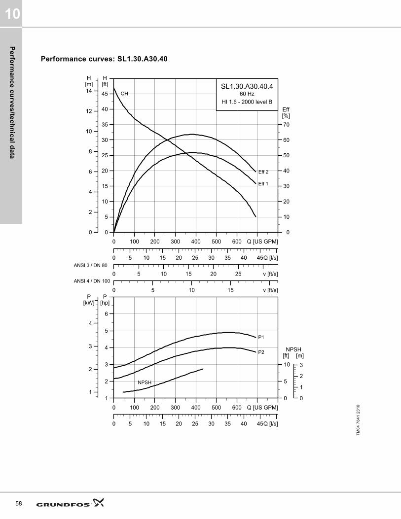
Pe
rform
an
ce
cu
rve
s/te
ch
nic
al d
ata
10
58
Performance curves: SL1.30.A30.40
TM
04
78
41
23
10
0 100 200 300 400 500 600 Q [US GPM]
0
5
10
15
20
25
30
35
40
45
[ft]H
0 5 10 15 20 25 v [ft/s]
0
10
20
30
40
50
60
70
[%]Eff
0 5 10 15 v [ft/s]
0 5 10 15 20 25 30 35 40 45Q [l/s]
0
2
4
6
8
10
12
14[m]H
SL1.30.A30.40.460 Hz
HI 1.6 - 2000 level B
Eff 1
Eff 2
QH
ANSI 3 / DN 80
ANSI 4 / DN 100
0 100 200 300 400 500 600 Q [US GPM]
1
2
3
4
5
6
[hp]P
0 5 10 15 20 25 30 35 40 45Q [l/s]
0
5
10
[ft]NPSH
1
2
3
4
[kW]P
0
1
2
3
[m]
P1
P2
NPSH

Pe
rfo
rma
nc
e c
urv
es
/te
ch
nic
al
da
ta
10
Dimensional sketches: SL1.30.A30.40
Electrical data
Pump data
TM
04
27
93
30
08
/TM
04
27
94
30
08
/TM
04
27
95
30
08
A C D E F H DN1 Dc1 DØ1 D1n DN2 Dc2 DØ2 D2n Weight [lb/kg]
[inch] 28 19.9 7.9 12.6 15.6 4.6 4 7.5 8xM16 3 6 8x0.75 306.9
[mm] 711 505 200 319 397 118 100 190.5 8xM16 80 152.4 8x19.1 139.2
Z2 Z3 Z4 Z6 Z7 Z8 Z9 Z10 Z11 Z12a Z14 Z15 Z16 ZDN1 ZM
[inch] 8.7 3.7 6.3 33.8 26.2 18.9 3.2 1.5 31.2 0.03 0.510 6.7 13.6 3 4xM16
[mm] 220 95 160 858 666 480 81 1.5 793 82 13 171 345 80 4xM16
V1 V2 V3 V4 V5 V6 V7 VØ
[inch] 33.1 15.4 5.1 14 11.8 24.5 3.2 0.7
[mm] 841 390 130 355 300 623 80 19
Pump typeVoltage
[V]
P1 [hp] (kW)
P2 [hp] (kW)
No of poles
RPMStarting method
IN Istart ηmotor [%] Cos ϕ
SF
Moment of inertia
[lb*ft2
(kgm2)]
Breakdown torque Mmax
[lbf*ft (Nm)][A] [A] 1/2 3/4 1/1 1/2 3/4 1/1
SL1.30.A30.40.4.61J3x208-230V D
/460V Y5
(3.7)4 (3) 4 1760 SD 12 79.5 76 79.8 80.2 0.69 0.80 0.84 1.15
1.35 (0.0569)
38.35 (52)
SL1.30.A30.40.4.61L 3x575V D5
(3.7)4 (3) 4 1750 SD 4.8 37.5 75 79.4 81.4 0.61 0.72 0.80 1.15
1.35 (0.0569)
46.47 (63)
SL1.30.A30.40.4.61H 3x460V D5
(3.7)4 (3) 4 1760 SD 6.2 51.5 74.6 79.7 81.5 0.56 0.68 0.77 1.15
1.35 (0.0569)
50.89 (69)
Impeller type
Max. solids size
Pump housing pressure
Max. number of starts per hour
Max. installation depth
Enclosure class
Insulation class
Temperature rise class
Max. liquid temperature
pH
[Inch / mm] PN [Feet / m] [°F / °C]
Single-channel 3 / 80 10 20 65 / 20 IP68 H A 104 / 40 4-14
59
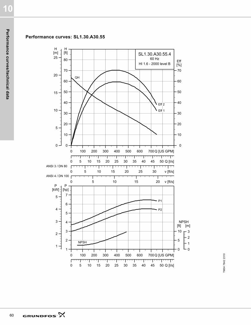
Pe
rform
an
ce
cu
rve
s/te
ch
nic
al d
ata
10
60
Performance curves: SL1.30.A30.55
TM
04
78
42
23
10
0 100 200 300 400 500 600 700 Q [US GPM]
0
10
20
30
40
50
60
70
80
[ft]H
0 5 10 15 20 25 30 v [ft/s]
0
10
20
30
40
50
60
70
[%]Eff
0 5 10 15 20 v [ft/s]
0 5 10 15 20 25 30 35 40 45 50 Q [l/s]
0
5
10
15
20
25[m]H
SL1.30.A30.55.460 Hz
HI 1.6 - 2000 level B
Eff 2
Eff 1
QH
ANSI 3 / DN 80
ANSI 4 / DN 100
0 100 200 300 400 500 600 700 Q [US GPM]
1
2
3
4
5
6
7
[hp]P
0 5 10 15 20 25 30 35 40 45 50 Q [l/s]
0
5
10
[ft]NPSH
1
2
3
4
5
[kW]P
0
1
2
3
[m]
NPSH
P2
P1

Pe
rfo
rma
nc
e c
urv
es
/te
ch
nic
al
da
ta
10
Dimensional sketches: SL1.30.A30.55
Electrical data
Pump data
TM
04
27
93
30
08
/TM
04
27
94
30
08
/TM
04
27
95
30
08
A C D E F H DN1 Dc1 DØ1 D1n DN2 Dc2 DØ2 D2n Weight [lb/kg]
[inch] 29.4 19.9 7.9 12.6 15.6 4.6 4 7.5 8xM16 3 6 8x0.75 318.3
[mm] 748 505 200 319 397 118 100 190.5 8xM16 80 152.4 8x19.1 144.4
Z2 Z3 Z4 Z6 Z7 Z8 Z9 Z10 Z11 Z12a Z14 Z15 Z16 ZDN1 ZM
[inch] 8.7 3.7 6.3 33.8 26.2 18.9 3.2 1.5 32.7 0.03 0.510 6.7 13.6 3 4xM16
[mm] 220 95 160 858 666 480 81 1.5 830 82 13 171 345 80 4xM16
V1 V2 V3 V4 V5 V6 V7 VØ
[inch] 34.6 15.4 5.1 14 11.8 24.5 3.2 0.7
[mm] 878 390 130 355 300 623 80 19
Pump typeVoltage
[V]
P1 [hp] (kW)
P2 [hp] (kW)
No of poles
RPMStarting method
IN Istart ηmotor [%] Cos ϕ
SF
Moment of inertia
[lb*ft2
(kgm2)]
Breakdown torque Mmax
[lbf*ft (Nm)][A] [A] 1/2 3/4 1/1 1/2 3/4 1/1
SL1.30.A30.55.4.61J3x208-230V D
/460V Y6.4
(4.8)5.5 (4)
4 1760 SD 16.1 79.4 79.9 83.3 83.9 0.61 0.74 0.80 1.151.73
(0.073)81.58
(110.6)
SL1.30.A30.55.4.61L 3x575V D6.4
(4.8)5.5 (4)
4 1765 SD 6.5 37.5 79.2 83.3 84.7 0.54 0.67 0.75 1.151.73
(0.073)68.59 (93)
SL1.30.A30.55.4.61H 3x460V D6.4
(4.8)5.5 (4)
4 1770 SD 8.5 51.5 78.3 82.6 84.4 0.50 0.64 0.72 1.151.73
(0.073)74.49 (101)
Impeller type
Max. solids size
Pump housing pressure
Max. number of starts per hour
Max. installation depth
Enclosure class
Insulation class
Temperature rise class
Max. liquid temperature
pH
[Inch / mm] PN [Feet / m] [°F / °C]
Single-channel 3 / 80 10 20 65 / 20 IP68 H A 104 / 40 4-14
61

Pe
rform
an
ce
cu
rve
s/te
ch
nic
al d
ata
10
62
Performance curves: SL1.30.A30.75
TM
04
78
43
23
10
0 100 200 300 400 500 600 700 Q [US GPM]
0
10
20
30
40
50
60
70
80
[ft]H
0 5 10 15 20 25 30 35 v [ft/s]
0
10
20
30
40
50
60
70
[%]Eff
0 5 10 15 20 v [ft/s]
0 5 10 15 20 25 30 35 40 45 50 55 Q [l/s]
0
5
10
15
20
25[m]H
SL1.30.A30.75.460 Hz
HI 1.6 - 2000 level B
QH
Eff 1
Eff 2
ANSI 3 / DN 80
ANSI 4 / DN 100
0 100 200 300 400 500 600 700 Q [US GPM]
3
4
5
6
7
8
9
[hp]P
0 5 10 15 20 25 30 35 40 45 50 55 Q [l/s]
0
5
10
[ft]NPSH
3
4
5
6
[kW]P
0
1
2
3
[m]
P1
P2
NPSH

Pe
rfo
rma
nc
e c
urv
es
/te
ch
nic
al
da
ta
10
Dimensional sketches: SL1.30.A30.75
Electrical data
Pump data
TM
04
27
93
30
08
/TM
04
27
94
30
08
/TM
04
27
95
30
08
A C D E F H DN1 Dc1 DØ1 D1n DN2 Dc2 DØ2 D2n Weight [lb/kg]
[inch] 29.7 19.9 7.9 12.6 15.6 4.6 4 7.5 8xM16 3 6 8x0.75 332.7
[mm] 755 505 200 319 397 118 100 190.5 8xM16 80 152.4 8x19.1 150.9
Z2 Z3 Z4 Z6 Z7 Z8 Z9 Z10 Z11 Z12a Z14 Z15 Z16 ZDN1 ZM
[inch] 8.7 3.7 6.3 33.8 26.2 18.9 3.2 1.5 33 0.03 0.51 6.7 13.6 3 4xM16
[mm] 220 95 160 858 666 480 81 1.5 837 82 13 171 345 80 4xM16
V1 V2 V3 V4 V5 V6 V7 VØ
[inch] 34.8 15.4 5.1 14 11.8 24.5 3.2 0.7
[mm] 885 390 130 355 300 623 80 19
Pump typeVoltage
[V]
P1 [hp] (kW)
P2 [hp] (kW)
No of poles
RPMStarting method
IN Istart ηmotor [%] Cos ϕ
SF
Moment of inertia
[lb*ft2
(kgm2)]
Breakdown torque Mmax
[lbf*ft (Nm)][A] [A] 1/2 3/4 1/1 1/2 3/4 1/1
SL1.30.A30.75.4.61J3x208-230V D
/460 V Y8.6
(6.4)7.5
(5.5)4 1760 SD 20 126 83.2 85.6 85.8 0.77 0.84 0.87 1.15
2.39 (0.10056)
90.41 (122.58)
SL1.30.A30.75.4.61L 3x575V D8.6
(6.4)7.5
(5.5)4 1765 SD 7.8 59.3 83.5 86.6 87.3 0.69 0.79 0.84 1.15
2.39 (0.10056)
75.97 (103)
SL1.30.A30.75.4.61H 3x460V D8.6
(6.4)7.5
(5.5)4 1770 SD 10 81.4 82.9 86.3 87.2 0.65 0.75 0.81 1.15
2.39 (0.10056)
83.34 (113)
Impeller type
Max. solids size
Pump housing pressure
Max. number of starts per hour
Max. installation depth
Enclosure class
Insulation class
Temperature rise class
Max. liquid temperature
pH
[Inch / mm] PN [Feet / m] [°F / °C]
Single-channel 3 / 80 10 20 65 / 20 IP68 H A 104 / 40 4-14
63
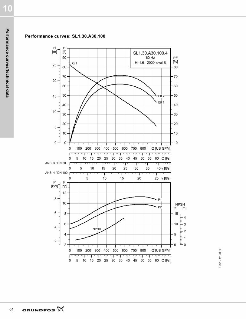
Pe
rform
an
ce
cu
rve
s/te
ch
nic
al d
ata
10
64
Performance curves: SL1.30.A30.100
TM
04
78
44
23
10
0 100 200 300 400 500 600 700 800 Q [US GPM]
0
10
20
30
40
50
60
70
80
90
[ft]H
0 5 10 15 20 25 30 35 40 v [ft/s]
0
10
20
30
40
50
60
70
80
[%]Eff
0 5 10 15 20 25 v [ft/s]
0 5 10 15 20 25 30 35 40 45 50 55 60 Q [l/s]
0
5
10
15
20
25
[m]H
SL1.30.A30.100.460 Hz
HI 1.6 - 2000 level BQH
Eff 1
Eff 2
ANSI 3 / DN 80
ANSI 4 / DN 100
0 100 200 300 400 500 600 700 800 Q [US GPM]
2
4
6
8
10
12
[hp]P
0 5 10 15 20 25 30 35 40 45 50 55 60 Q [l/s]
0
5
10
15
[ft]NPSH
2
4
6
8
[kW]P
0
1
2
3
4
[m]
P1
P2
NPSH

Pe
rfo
rma
nc
e c
urv
es
/te
ch
nic
al
da
ta
10
Dimensional sketches: SL1.30.A30.100
Electrical data
Pump data
TM
04
27
93
30
08
/TM
04
27
94
30
08
/TM
04
27
95
30
08
A C D E F H DN1 Dc1 DØ1 D1n DN2 Dc2 DØ2 D2n Weight [lb/kg]
[inch] 32.2 20.9 8.5 12.9 16.7 4.6 4 7.5 8xM16 3 6 8 x 0.75 435.9
[mm] 818 530 217 328 423 115 100 190.5 8xM16 80 152.4 8 x 19.1 197.7
Z2 Z3 Z4 Z6 Z7 Z8 Z9 Z10 Z11 Z12a Z14 Z15 Z16 ZDN1 ZM
[inch] 8.7 3.7 6.3 34.8 27.2 19.3 3.2 1.5 35.4 0.03 0.510 6.7 13.6 3 4xM16
[mm] 220 95 160 883 690 489 81 1.5 900 85 13 171 345 80 4xM16
V1 V2 V3 V4 V5 V6 V7 VØ
[inch] 37.3 15.4 5.1 14 11.8 25.5 3.2 0.7
[mm] 948 390 130 355 300 648 80 19
Pump typeVoltage
[V]
P1 [hp] (kW)
P2 [hp] (kW)
No
of
po
les
RPMStarting method
IN Istart ηmotor [%] Cos ϕ
SF
Moment of inertia
[lb*ft2
(kgm2)]
Breakdown torque Mmax
[lbf*ft (Nm)][A] [A] 1/2 3/4 1/1 1/2 3/4 1/1
SL1.30.A30.100.4.61J3x208-230V D
/460V Y11.5 (8.6)
10 (7.5)
4 1760 SD 26.6 174 85.6 86.9 86.4 0.80 0.86 0.89 1.153.18
(0.134)75.23 (102)
SL1.30.A30.100.4.61L 3x575V D11.5 (8.6)
10 (7.5)
4 1760 SD 10.2 81.2 85.3 87.4 87.9 0.74 0.83 0.86 1.153.18
(0.134)104.73 (142)
SL1.30.A30.100.4.61H 3x460V D11.5 (8.6)
10 (7.5)
4 1765 SD 13 111 85 87.6 88.1 0.70 0.80 0.85 1.153.18
(0.134)114.32 (155)
Impeller type
Max. solids size
Pump housing pressure
Max. number of starts per hour
Max. installation depth
Enclosure class
Insulation class
Temperature rise class
Max. liquid temperature
pH
[Inch / mm] PN [Feet / m] [°F / °C]
Single-channel 3 / 80 10 20 65 / 20 IP68 H A 104 / 40 4-14
65
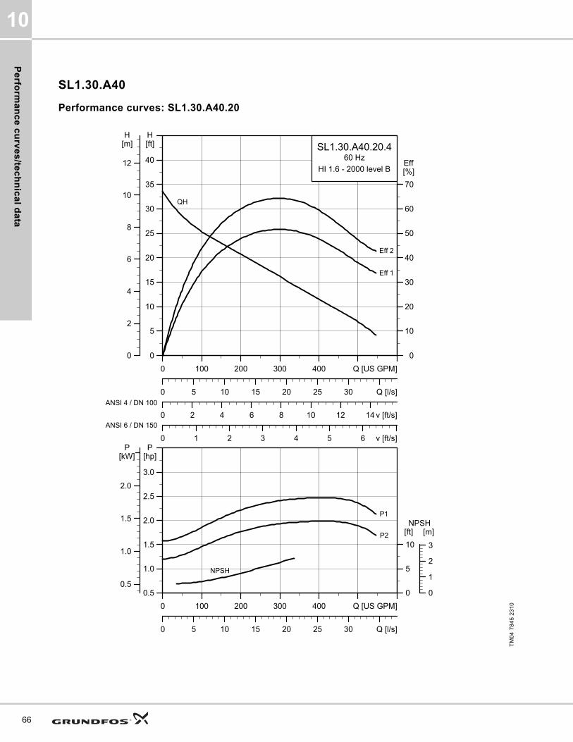
Pe
rform
an
ce
cu
rve
s/te
ch
nic
al d
ata
10
66
SL1.30.A40
Performance curves: SL1.30.A40.20
TM
04
78
45
23
10
0 100 200 300 400 Q [US GPM]
0
5
10
15
20
25
30
35
40
[ft]H
0 2 4 6 8 10 12 14 v [ft/s]
0
10
20
30
40
50
60
70
[%]Eff
0 1 2 3 4 5 6 v [ft/s]
0 5 10 15 20 25 30 Q [l/s]
0
2
4
6
8
10
12
[m]H
SL1.30.A40.20.460 Hz
HI 1.6 - 2000 level B
QH
Eff 1
Eff 2
ANSI 4 / DN 100
ANSI 6 / DN 150
0 100 200 300 400 Q [US GPM]
0.5
1.0
1.5
2.0
2.5
3.0
[hp]P
0 5 10 15 20 25 30 Q [l/s]
0
5
10
[ft]NPSH
0.5
1.0
1.5
2.0
[kW]P
0
1
2
3
[m]
P1
P2
NPSH

Pe
rfo
rma
nc
e c
urv
es
/te
ch
nic
al
da
ta
10
Dimensional sketches: SL1.30.A40.20
Electrical data
Pump data
TM
04
27
93
30
08
/TM
04
27
94
30
08
/TM
04
27
95
30
08
A C D E F H DN1 Dc1 DØ1 D1n DN2 Dc2 DØ2 D2n Weight [lb/kg]
[inch] 26.9 17.1 6.7 10.7 13.7 4.4 4 7.5 8xM16 4 7.5 8x0.75 214.3
[mm] 682 435 171 272 347 90 100 190.5 8xM16 100 190.5 8x19.1 97.2
Z2 Z3 Z4 Z6 Z7 Z8 Z9 Z10 Z11 Z12a Z14 Z15 Z16 ZDN1 ZM
[inch] 10.2 4.3 8.7 34.6 25.7 19.3 4.3 2 32.7 0.03 0 8.7 16.3 4 4xM16
[mm] 260 110 220 878 652 489 110 2 830 150 0 220 413 100 4xM16
V1 V2 V3 V4 V5 V6 V7 VØ
[inch] 32 14.5 5.1 13.976 11.8 23.3 3.9 0.7
[mm] 812 369 130 355 300 591 100 19
Pump typeVoltage
[V]
P1 [hp] (kW)
P2 [hp] (kW)
No of poles
RPMStarting method
IN Istart ηmotor [%] Cos ϕ
SF
Moment of inertia
[lb*ft2
(kgm2)]
Breakdown torque Mmax
[lbf*ft (Nm)][A] [A] 1/2 3/4 1/1 1/2 3/4 1/1
SL1.30.A40.20.4.60J3x208-230V D
/460V Y2.5
(1.9)2
(1.5)4 1750 DOL 6.6 42.5 69.6 74.4 76.2 0.65 0.74 0.80 1.15
0.67 (0.0284)
19.18 (26)
SL1.30.A40.20.4.60L 3x575V D2.5
(1.9)2
(1.5)4 1750 DOL 2.6 20 68.7 74.4 77 0.59 0.69 0.76 1.15
0.67 (0.0284)
22.86 (31)
SL1.30.A40.20.4.61L 3x575V D2.5
(1.9)2
(1.5)4 1750 SD 2.6 20 68.7 74.4 77 0.59 0.69 0.76 1.15
0.67 (0.0284)
22.86 (31)
SL1.30.A40.20.4.61J3x208-230V D
/460 V Y2.5
(1.9)2
(1.5)4 1750 SD 6.6 42.5 69.6 74.4 76.2 0.65 0.74 0.80 1.15
0.67 (0.0284)
19.18 (26)
Impeller type
Max. solids size
Pump housing pressure
Max. number of starts per hour
Max. installation depth
Enclosure class
Insulation class
Temperature rise class
Max. liquid temperature
pH
[Inch / mm] PN [Feet / m] [°F / °C]
Single-channel 3 / 80 10 20 65 / 20 IP68 H A 104 / 40 4-14
67
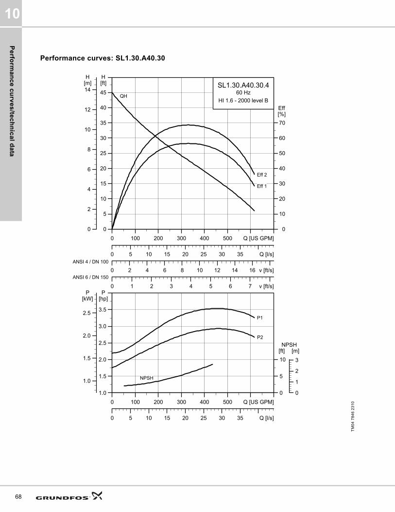
Pe
rform
an
ce
cu
rve
s/te
ch
nic
al d
ata
10
68
Performance curves: SL1.30.A40.30
TM
04
78
46
23
10
0 100 200 300 400 500 Q [US GPM]
0
5
10
15
20
25
30
35
40
45
[ft]H
0 2 4 6 8 10 12 14 16 v [ft/s]
0
10
20
30
40
50
60
70
[%]Eff
0 1 2 3 4 5 6 7 v [ft/s]
0 5 10 15 20 25 30 35 Q [l/s]
0
2
4
6
8
10
12
14[m]H
SL1.30.A40.30.460 Hz
HI 1.6 - 2000 level B
Eff 2
Eff 1
QH
ANSI 4 / DN 100
ANSI 6 / DN 150
0 100 200 300 400 500 Q [US GPM]
1.0
1.5
2.0
2.5
3.0
3.5
[hp]P
0 5 10 15 20 25 30 35 Q [l/s]
0
5
10
[ft]NPSH
1.0
1.5
2.0
2.5
[kW]P
0
1
2
3
[m]
NPSH
P2
P1

Pe
rfo
rma
nc
e c
urv
es
/te
ch
nic
al
da
ta
10
Dimensional sketches: SL1.30.A40.30
Electrical data
Pump data
TM
04
27
93
30
08
/TM
04
27
94
30
08
/TM
04
27
95
30
08
A C D E F H DN1 Dc1 DØ1 D1n DN2 Dc2 DØ2 D2n Weight [lb/kg]
[inch] 26.9 17.1 6.7 10.7 13.7 4.4 4 7.5 8xM16 4 7.5 8x0.75 244.7
[mm] 682 435 171 272 347 90 100 190.5 8xM16 100 190.5 8x19.1 111
Z2 Z3 Z4 Z6 Z7 Z8 Z9 Z10 Z11 Z12a Z14 Z15 Z16 ZDN1 ZM
[inch] 10.2 4.3 8.7 34.6 25.7 19.3 4.3 2 32.7 0.03 0 8.7 16.3 4 4xM16
[mm] 260 110 220 878 652 489 110 2 830 150 0 220 413 100 4xM16
V1 V2 V3 V4 V5 V6 V7 VØ
[inch] 32 14.5 5.1 13.976 11.8 23.3 3.9 0.7
[mm] 812 369 130 355 300 591 100 19
Pump typeVoltage
[V]
P1 [hp] (kW)
P2 [hp] (kW)
No of poles
RPMStarting method
IN Istart ηmotor [%] Cos ϕ
SF
Moment of inertia
[lb*ft2
(kgm2)]
Breakdown torque Mmax
[lbf*ft (Nm)][A] [A] 1/2 3/4 1/1 1/2 3/4 1/1
SL1.30.A40.30.4.61J3x208-230V D
/460 V Y3.6
(2.7)3
(2.2)4 1750 SD 8.7 61.6 78.2 81.5 82.1 0.69 0.78 0.83 1.15
1.02 (0.0429)
26.55 (36)
SL1.30.A40.30.4.61H 3x460V D3.6
(2.7)3
(2.2)4 1770 SD 4.5 39.7 76.9 80.7 83 0.57 0.69 0.76 1.15
1.02 (0.0429)
35.4 (48)
SL1.30.A40.30.4.61L 3x575V D3.6
(2.7)3
(2.2)4 1760 SD 3.5 29 77.5 81.3 82.9 0.62 0.72 0.79 1.15
1.02 (0.0429)
32.45 (44)
Impeller type
Max. solids size
Pump housing pressure
Max. number of starts per hour
Max. installation depth
Enclosure class
Insulation class
Temperature rise class
Max. liquid temperature
pH
[Inch / mm] PN [Feet / m] [°F / °C]
Single-channel 3 / 80 10 20 65 / 20 IP68 H A 104 / 40 4-14
69
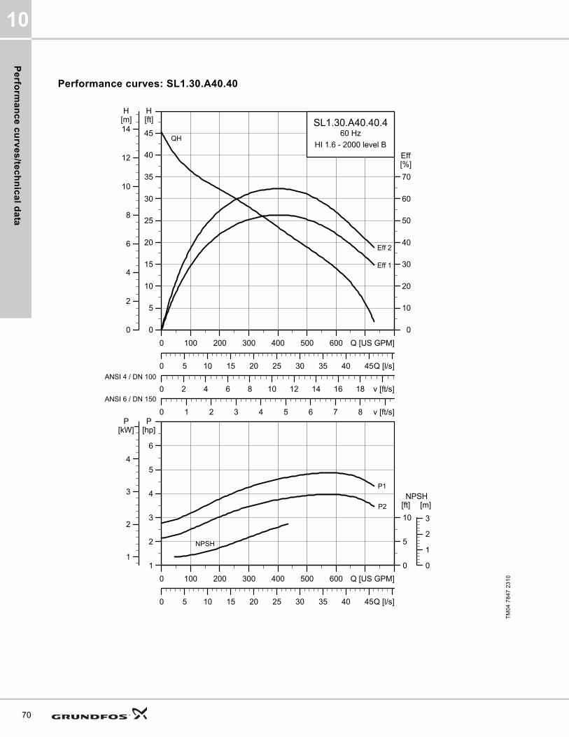
Pe
rform
an
ce
cu
rve
s/te
ch
nic
al d
ata
10
70
Performance curves: SL1.30.A40.40
TM
04
78
47
23
10
0 100 200 300 400 500 600 Q [US GPM]
0
5
10
15
20
25
30
35
40
45
[ft]H
0 2 4 6 8 10 12 14 16 18 v [ft/s]
0
10
20
30
40
50
60
70
[%]Eff
0 1 2 3 4 5 6 7 8 v [ft/s]
0 5 10 15 20 25 30 35 40 45Q [l/s]
0
2
4
6
8
10
12
14[m]H
SL1.30.A40.40.460 Hz
HI 1.6 - 2000 level BQH
Eff 1
Eff 2
ANSI 4 / DN 100
ANSI 6 / DN 150
0 100 200 300 400 500 600 Q [US GPM]
1
2
3
4
5
6
[hp]P
0 5 10 15 20 25 30 35 40 45Q [l/s]
0
5
10
[ft]NPSH
1
2
3
4
[kW]P
0
1
2
3
[m]
P1
P2
NPSH

Pe
rfo
rma
nc
e c
urv
es
/te
ch
nic
al
da
ta
10
Dimensional sketches: SL1.30.A40.40
Electrical data
Pump data
TM
04
27
93
30
08
/TM
04
27
94
30
08
/TM
04
27
95
30
08
A C D E F H DN1 Dc1 DØ1 D1n DN2 Dc2 DØ2 D2n Weight [lb/kg]
[inch] 28.6 19.9 7.9 12.6 15.6 4.6 4 7.5 8xM16 4 7.5 8x0.75 309.1
[mm] 726 505 200 319 397 115 100 190.5 8xM16 100 190.5 8x19.1 140.2
Z2 Z3 Z4 Z6 Z7 Z8 Z9 Z10 Z11 Z12a Z14 Z15 Z16 ZDN1 ZM
[inch] 10.2 4.3 8.7 37.3 28.4 21.1 4.3 2 32.7 0.03 0 8.7 16.3 4 4xM16
[mm] 260 110 220 948 722 536 110 2 830 125 0 220 413 100 4xM16
V1 V2 V3 V4 V5 V6 V7 VØ
[inch] 33.7 15.6 5.1 13.976 11.8 25.5 3.9 0.7
[mm] 856 395 130 355 300 647 100 19
Pump typeVoltage
[V]
P1 [hp] (kW)
P2 [hp] (kW)
No of poles
RPMStarting method
IN Istart ηmotor [%] Cos ϕ
SF
Moment of inertia
[lb*ft2
(kgm2)]
Breakdown torque Mmax
[lbf*ft (Nm)][A] [A] 1/2 3/4 1/1 1/2 3/4 1/1
SL1.30.A40.40.4.61J3x208-230V D
/460V Y5
(3.7)4 (3) 4 1760 SD 12 79.5 76 79.8 80.2 0.69 0.80 0.84 1.15
1.35 (0.0569)
38.35 (52)
SL1.30.A40.40.4.61L 3x575V D5
(3.7)4 (3) 4 1750 SD 4.8 37.5 75 79.4 81.4 0.61 0.72 0.80 1.15
1.35 (0.0569)
46.47 (63)
SL1.30.A40.40.4.61H 3x460V D5
(3.7)4 (3) 4 1760 SD 6.2 51.5 74.6 79.7 81.5 0.56 0.68 0.77 1.15
1.35 (0.0569)
50.89 (69)
Impeller type
Max. solids size
Pump housing pressure
Max. number of starts per hour
Max. installation depth
Enclosure class
Insulation class
Temperature rise class
Max. liquid temperature
pH
[Inch / mm] PN [Feet / m] [°F / °C]
Single-channel 3 / 80 10 20 65 / 20 IP68 H A 104 / 40 4-14
71
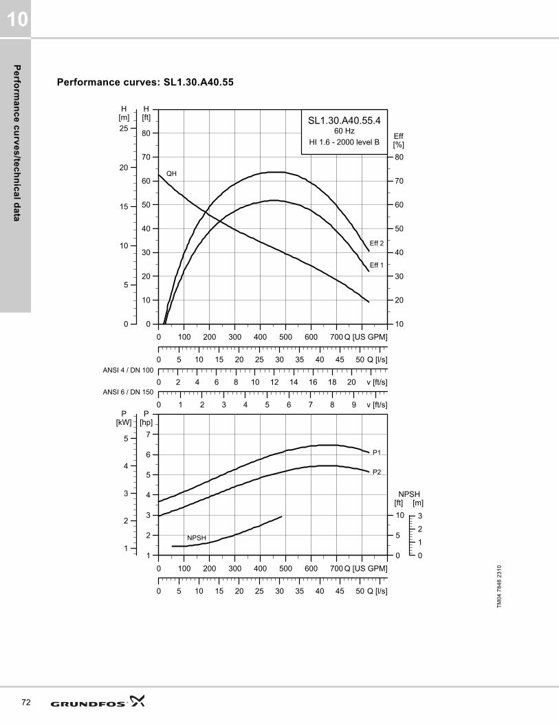
Pe
rform
an
ce
cu
rve
s/te
ch
nic
al d
ata
10
72
Performance curves: SL1.30.A40.55
TM
04
78
48
23
10
0 100 200 300 400 500 600 700 Q [US GPM]
0
10
20
30
40
50
60
70
80
[ft]H
0 2 4 6 8 10 12 14 16 18 20 v [ft/s]
10
20
30
40
50
60
70
80
[%]Eff
0 1 2 3 4 5 6 7 8 9 v [ft/s]
0 5 10 15 20 25 30 35 40 45 50 Q [l/s]
0
5
10
15
20
25[m]H
SL1.30.A40.55.460 Hz
HI 1.6 - 2000 level B
Eff 2
Eff 1
QH
ANSI 4 / DN 100
ANSI 6 / DN 150
0 100 200 300 400 500 600 700 Q [US GPM]
1
2
3
4
5
6
7
[hp]P
0 5 10 15 20 25 30 35 40 45 50 Q [l/s]
0
5
10
[ft]NPSH
1
2
3
4
5
[kW]P
0
1
2
3
[m]
NPSH
P2
P1

Pe
rfo
rma
nc
e c
urv
es
/te
ch
nic
al
da
ta
10
Dimensional sketches: SL1.30.A40.55
Electrical data
Pump data
TM
04
27
93
30
08
/TM
04
27
94
30
08
/TM
04
27
95
30
08
A C D E F H DN1 Dc1 DØ1 D1n DN2 Dc2 DØ2 D2n Weight [lb/kg]
[inch] 29.4 19.9 7.9 12.6 15.6 4.6 4 7.5 8xM16 4 7.5 8x0.75 320.6
[mm] 748 505 200 319 397 115 100 190.5 8xM16 100 190.5 8x19.1 145.4
Z2 Z3 Z4 Z6 Z7 Z8 Z9 Z10 Z11 Z12a Z14 Z15 Z16 ZDN1 ZM
[inch] 10.2 4.3 8.7 37.3 28.4 21.1 4.3 2 34.3 0.03 0 8.7 16.3 4 4xM16
[mm] 260 110 220 948 722 536 110 2 870 125 0 220 413 100 4xM16
V1 V2 V3 V4 V5 V6 V7 VØ
[inch] 34.6 15.6 5.1 13.976 11.8 25.5 3.9 0.7
[mm] 878 395 130 355 300 647 100 19
Pump typeVoltage
[V]
P1 [hp] (kW)
P2 [hp] (kW)
No of poles
RPMStarting method
IN Istart ηmotor [%] Cos ϕ
SF
Moment of inertia
[lb*ft2
(kgm2)]
Breakdown torque Mmax
[lbf*ft (Nm)][A] [A] 1/2 3/4 1/1 1/2 3/4 1/1
SL1.30.A40.55.4.61J3x208-230V D
/460V Y6.4
(4.8)5.5 (4)
4 1760 SD 16.1 79.4 79.9 83.3 83.9 0.61 0.74 0.80 1.151.73
(0.073)81.58
(110.6)
SL1.30.A40.55.4.61L 3x575V D6.4
(4.8)5.5 (4)
4 1765 SD 6.5 37.5 79.2 83.3 84.7 0.54 0.67 0.75 1.151.73
(0.073)68.59 (93)
SL1.30.A40.55.4.61H 3x460V D6.4
(4.8)5.5 (4)
4 1770 SD 8.5 51.5 78.3 82.6 84.4 0.50 0.64 0.72 1.151.73
(0.073)74.49 (101)
Impeller type
Max. solids size
Pump housing pressure
Max. number of starts per hour
Max. installation depth
Enclosure class
Insulation class
Temperature rise class
Max. liquid temperature
pH
[Inch / mm] PN [Feet / m] [°F / °C]
Single-channel 3 / 80 10 20 65 / 20 IP68 H A 104 / 40 4-14
73
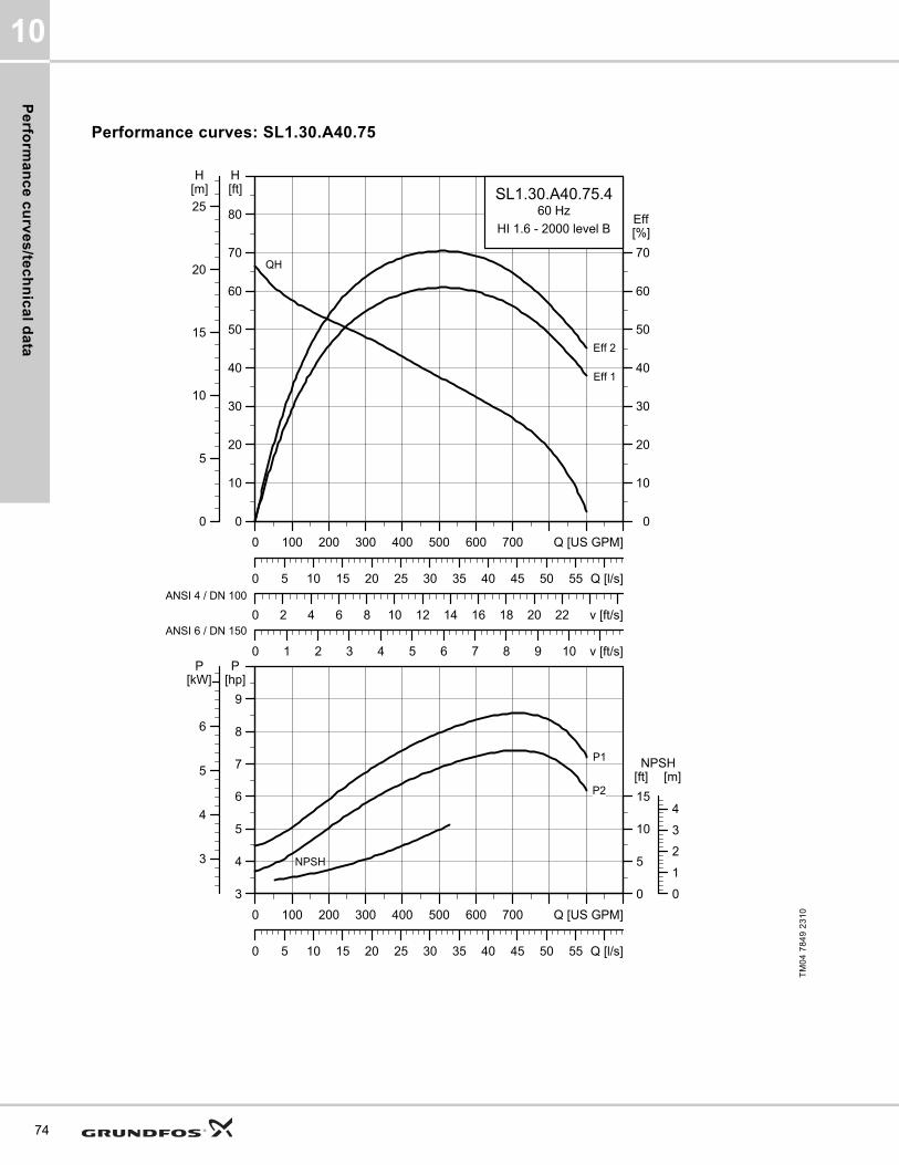
Pe
rform
an
ce
cu
rve
s/te
ch
nic
al d
ata
10
74
Performance curves: SL1.30.A40.75
TM
04
78
49
23
10
0 100 200 300 400 500 600 700 Q [US GPM]
0
10
20
30
40
50
60
70
80
[ft]H
0 2 4 6 8 10 12 14 16 18 20 22 v [ft/s]
0
10
20
30
40
50
60
70
[%]Eff
0 1 2 3 4 5 6 7 8 9 10 v [ft/s]
0 5 10 15 20 25 30 35 40 45 50 55 Q [l/s]
0
5
10
15
20
25[m]H
SL1.30.A40.75.460 Hz
HI 1.6 - 2000 level B
QH
Eff 1
Eff 2
ANSI 4 / DN 100
ANSI 6 / DN 150
0 100 200 300 400 500 600 700 Q [US GPM]
3
4
5
6
7
8
9
[hp]P
0 5 10 15 20 25 30 35 40 45 50 55 Q [l/s]
0
5
10
15
[ft]NPSH
3
4
5
6
[kW]P
0
1
2
3
4
[m]
P1
P2
NPSH
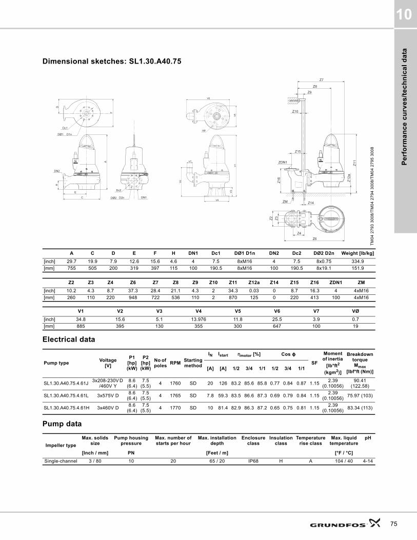
Pe
rfo
rma
nc
e c
urv
es
/te
ch
nic
al
da
ta
10
Dimensional sketches: SL1.30.A40.75
Electrical data
Pump data
TM
04
27
93
30
08
/TM
04
27
94
30
08
/TM
04
27
95
30
08
A C D E F H DN1 Dc1 DØ1 D1n DN2 Dc2 DØ2 D2n Weight [lb/kg]
[inch] 29.7 19.9 7.9 12.6 15.6 4.6 4 7.5 8xM16 4 7.5 8x0.75 334.9
[mm] 755 505 200 319 397 115 100 190.5 8xM16 100 190.5 8x19.1 151.9
Z2 Z3 Z4 Z6 Z7 Z8 Z9 Z10 Z11 Z12a Z14 Z15 Z16 ZDN1 ZM
[inch] 10.2 4.3 8.7 37.3 28.4 21.1 4.3 2 34.3 0.03 0 8.7 16.3 4 4xM16
[mm] 260 110 220 948 722 536 110 2 870 125 0 220 413 100 4xM16
V1 V2 V3 V4 V5 V6 V7 VØ
[inch] 34.8 15.6 5.1 13.976 11.8 25.5 3.9 0.7
[mm] 885 395 130 355 300 647 100 19
Pump typeVoltage
[V]
P1 [hp] (kW)
P2 [hp] (kW)
No of poles
RPMStarting method
IN Istart ηmotor [%] Cos ϕ
SF
Moment of inertia
[lb*ft2
(kgm2)]
Breakdown torque Mmax
[lbf*ft (Nm)][A] [A] 1/2 3/4 1/1 1/2 3/4 1/1
SL1.30.A40.75.4.61J3x208-230V D
/460V Y8.6
(6.4)7.5
(5.5)4 1760 SD 20 126 83.2 85.6 85.8 0.77 0.84 0.87 1.15
2.39 (0.10056)
90.41 (122.58)
SL1.30.A40.75.4.61L 3x575V D8.6
(6.4)7.5
(5.5)4 1765 SD 7.8 59.3 83.5 86.6 87.3 0.69 0.79 0.84 1.15
2.39 (0.10056)
75.97 (103)
SL1.30.A40.75.4.61H 3x460V D8.6
(6.4)7.5
(5.5)4 1770 SD 10 81.4 82.9 86.3 87.2 0.65 0.75 0.81 1.15
2.39 (0.10056)
83.34 (113)
Impeller type
Max. solids size
Pump housing pressure
Max. number of starts per hour
Max. installation depth
Enclosure class
Insulation class
Temperature rise class
Max. liquid temperature
pH
[Inch / mm] PN [Feet / m] [°F / °C]
Single-channel 3 / 80 10 20 65 / 20 IP68 H A 104 / 40 4-14
75
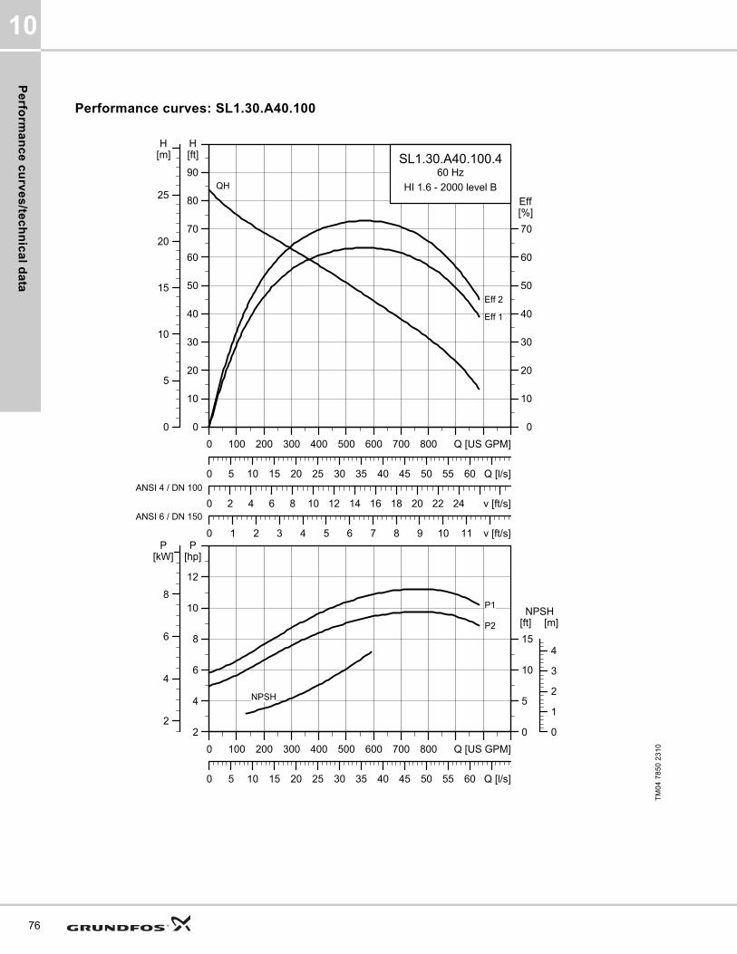
Pe
rform
an
ce
cu
rve
s/te
ch
nic
al d
ata
10
76
Performance curves: SL1.30.A40.100
TM
04
78
50
23
10
0 100 200 300 400 500 600 700 800 Q [US GPM]
0
10
20
30
40
50
60
70
80
90
[ft]H
0 2 4 6 8 10 12 14 16 18 20 22 24 v [ft/s]
0
10
20
30
40
50
60
70
[%]Eff
0 1 2 3 4 5 6 7 8 9 10 11 v [ft/s]
0 5 10 15 20 25 30 35 40 45 50 55 60 Q [l/s]
0
5
10
15
20
25
[m]H
SL1.30.A40.100.460 Hz
HI 1.6 - 2000 level BQH
Eff 1
Eff 2
ANSI 4 / DN 100
ANSI 6 / DN 150
0 100 200 300 400 500 600 700 800 Q [US GPM]
2
4
6
8
10
12
[hp]P
0 5 10 15 20 25 30 35 40 45 50 55 60 Q [l/s]
0
5
10
15
[ft]NPSH
2
4
6
8
[kW]P
0
1
2
3
4
[m]
P1
P2
NPSH

Pe
rfo
rma
nc
e c
urv
es
/te
ch
nic
al
da
ta
10
Dimensional sketches: SL1.30.A40.100
Electrical data
Pump data
TM
04
27
93
30
08
/TM
04
27
94
30
08
/TM
04
27
95
30
08
A C D E F H DN1 Dc1 DØ1 D1n DN2 Dc2 DØ2 D2n Weight [lb/kg]
[inch] 32.2 20.9 8.5 12.9 16.7 4.6 4 7.5 8xM16 4 7.5 8x0.75 437.8
[mm] 818 530 217 328 423 116 100 190.5 8xM16 100 190.5 8x19.1 198.6
Z2 Z3 Z4 Z6 Z7 Z8 Z9 Z10 Z11 Z12a Z14 Z15 Z16 ZDN1 ZM
[inch] 10.2 4.3 8.7 38.3 29.4 21.5 4.3 2 37 0.03 0 8.7 16.3 4 4xM16
[mm] 260 110 220 972 747 545 110 2 940 124 0 220 413 100 4xM16
V1 V2 V3 V4 V5 V6 V7 VØ
[inch] 37.3 15.6 5.1 13.976 11.8 26.5 3.9 0.7
[mm] 948 395 130 355 300 672 100 19
Pump typeVoltage
[V]
P1 [hp] (kW)
P2 [hp] (kW)
No
of
po
les
RPMStarting method
IN Istart ηmotor [%] Cos ϕ
SF
Moment of inertia
[lb*ft2
(kgm2)]
Breakdown torque Mmax
[lbf*ft (Nm)][A] [A] 1/2 3/4 1/1 1/2 3/4 1/1
SL1.30.A40.100.4.61J3x208-230V D
/460 V Y11.5 (8.6)
10 (7.5)
4 1760 SD 26.6 174 85.6 86.9 86.4 0.80 0.86 0.89 1.153.18
(0.134)75.23 (102)
SL1.30.A40.100.4.61L 3x575V D11.5 (8.6)
10 (7.5)
4 1760 SD 10.2 81.2 85.3 87.4 87.9 0.74 0.83 0.86 1.153.18
(0.134)104.73 (142)
SL1.30.A40.100.4.61H 3x460V D11.5 (8.6)
10 (7.5)
4 1765 SD 13 111 85 87.6 88.1 0.70 0.80 0.85 1.153.18
(0.134)114.32 (155)
Impeller type
Max. solids size
Pump housing pressure
Max. number of starts per hour
Max. installation depth
Enclosure class
Insulation class
Temperature rise class
Max. liquid temperature
pH
[Inch / mm] PN [Feet / m] [°F / °C]
Single-channel 3 / 80 10 20 65 / 20 IP68 H A 104 / 40 4-14
77
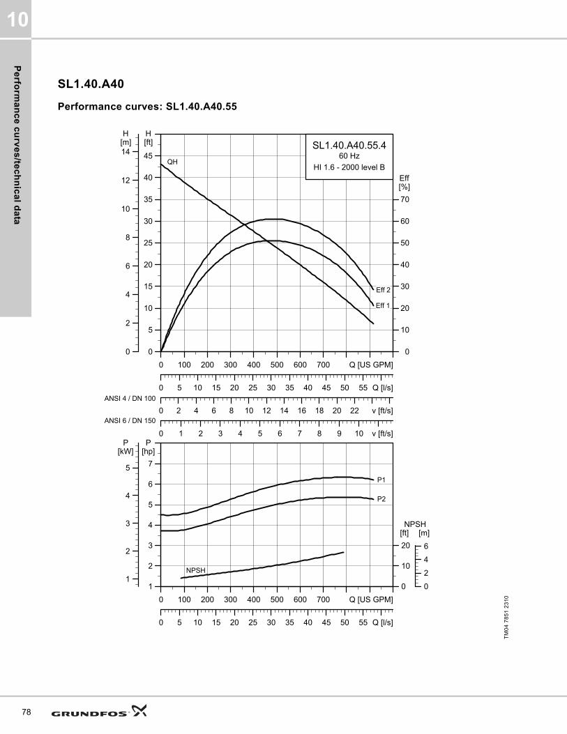
Pe
rform
an
ce
cu
rve
s/te
ch
nic
al d
ata
10
78
SL1.40.A40
Performance curves: SL1.40.A40.55
TM
04
78
51
23
10
0 100 200 300 400 500 600 700 Q [US GPM]
0
5
10
15
20
25
30
35
40
45
[ft]H
0 2 4 6 8 10 12 14 16 18 20 22 v [ft/s]
0
10
20
30
40
50
60
70
[%]Eff
0 1 2 3 4 5 6 7 8 9 10 v [ft/s]
0 5 10 15 20 25 30 35 40 45 50 55 Q [l/s]
0
2
4
6
8
10
12
14[m]H
SL1.40.A40.55.460 Hz
HI 1.6 - 2000 level B
Eff 2
Eff 1
QH
ANSI 4 / DN 100
ANSI 6 / DN 150
0 100 200 300 400 500 600 700 Q [US GPM]
1
2
3
4
5
6
7
[hp]P
0 5 10 15 20 25 30 35 40 45 50 55 Q [l/s]
0
10
20
[ft]NPSH
1
2
3
4
5
[kW]P
0
2
4
6
[m]
NPSH
P2
P1

Pe
rfo
rma
nc
e c
urv
es
/te
ch
nic
al
da
ta
10
Dimensional sketches: SL1.40.A40.55
Electrical data
Pump data
TM
04
27
93
30
08
/TM
04
27
94
30
08
/TM
04
27
95
30
08
A C D E F H DN1 Dc1 DØ1 D1n DN2 Dc2 DØ2 D2n Weight [lb/kg]
[inch] 29.7 21.3 7.9 12.6 17.2 4.5 6 9.5 8xM20 4 7.5 8x0.75 349.2
[mm] 755 541 200 320 438 134 150 241.30 8xM20 100 190.5 8x19.1 158.4
Z2 Z3 Z4 Z6 Z7 Z8 Z9 Z10 Z11 Z12a Z14 Z15 Z16 ZDN1 ZM
[inch] 10.2 4.3 8.7 38.7 29.8 21.1 4.3 2 34.6 0.04 0 8.7 16.3 4 4xM16
[mm] 260 110 220 983 758 537 110 2 879 106 0 220 413 100 4xM16
V1 V2 V3 V4 V5 V6 V7 VØ
[inch] 37 17.5 7.3 17.717 15.7 27.8 3.9 0.9
[mm] 941 445 186 450 400 711 100 22
Pump typeVoltage
[V]
P1 [hp] (kW)
P2 [hp] (kW)
No of poles
RPMStarting method
IN Istart ηmotor [%] Cos ϕ
SF
Moment of inertia
[lb*ft2
(kgm2)]
Breakdown torque Mmax
[lbf*ft (Nm)][A] [A] 1/2 3/4 1/1 1/2 3/4 1/1
SL1.40.A40.55.4.61J3x208-230V D
/460V Y6.4
(4.8)5.5 (4)
4 1760 SD 16.1 79.4 79.9 83.3 83.9 0.61 0.74 0.80 1.152.18
(0.092)81.58
(110.6)
SL1.40.A40.55.4.61L 3x575V D6.4
(4.8)5.5 (4)
4 1765 SD 6.5 37.5 79.2 83.3 84.7 0.54 0.67 0.75 1.152.18
(0.092)68.59 (93)
SL1.40.A40.55.4.61H 3x460V D6.4
(4.8)5.5 (4)
4 1770 SD 8.5 51.5 78.3 82.6 84.4 0.50 0.64 0.72 1.152.18
(0.092)74.49 (101)
Impeller type
Max. solids size
Pump housing pressure
Max. number of starts per hour
Max. installation depth
Enclosure class
Insulation class
Temperature rise class
Max. liquid temperature
pH
[Inch / mm] PN [Feet / m] [°F / °C]
Single-channel 4 / 100 10 20 65 / 20 IP68 H A 104 / 40 4-14
79

Pe
rform
an
ce
cu
rve
s/te
ch
nic
al d
ata
10
80
Performance curves: SL1.40.A40.75
TM
04
78
52
23
10
0 200 400 600 800 Q [US GPM]
0
5
10
15
20
25
30
35
40
45
50
55[ft]H
0 5 10 15 20 25 v [ft/s]
0
10
20
30
40
50
60
70
[%]Eff
0 2 4 6 8 10 12 v [ft/s]
0 10 20 30 40 50 60 Q [l/s]
0
2
4
6
8
10
12
14
16
[m]H
SL1.40.A40.75.460 Hz
HI 1.6 - 2000 level B
Eff 2
Eff 1
QH
ANSI 4 / DN 100
ANSI 6 / DN 150
0 200 400 600 800 Q [US GPM]
3
4
5
6
7
8
9
[hp]P
0 10 20 30 40 50 60 Q [l/s]
0
10
20
[ft]NPSH
3
4
5
6
[kW]P
0
2
4
6
[m]
NPSH
P2
P1

Pe
rfo
rma
nc
e c
urv
es
/te
ch
nic
al
da
ta
10
Dimensional sketches: SL1.40.A40.75
Electrical data
Pump data
TM
04
27
93
30
08
/TM
04
27
94
30
08
/TM
04
27
95
30
08
A C D E F H DN1 Dc1 DØ1 D1n DN2 Dc2 DØ2 D2n Weight [lb/kg]
[inch] 30 21.3 7.9 12.6 17.2 4.5 6 9.5 8xM20 4 7.5 8x0.75 364.4
[mm] 762 541 200 320 438 134 150 241.3 8xM20 100 190.5 8x19.1 165.3
Z2 Z3 Z4 Z6 Z7 Z8 Z9 Z10 Z11 Z12a Z14 Z15 Z16 ZDN1 ZM
[inch] 10.2 4.3 8.7 38.7 29.8 21.1 4.3 2 34.9 0.04 0 8.7 16.3 4 4xM16
[mm] 260 110 220 983 758 537 110 2 886 106 0 220 413 100 4xM16
V1 V2 V3 V4 V5 V6 V7 VØ
[inch] 37.3 17.5 7.3 17.717 15.7 27.8 3.9 0.9
[mm] 948 445 186 450 400 711 100 22
Pump typeVoltage
[V]
P1 [hp] (kW)
P2 [hp] (kW)
No of poles
RPMStarting method
IN Istart ηmotor [%] Cos ϕ
SF
Moment of inertia
[lb*ft2
(kgm2)]
Breakdown torque Mmax
[lbf*ft (Nm)][A] [A] 1/2 3/4 1/1 1/2 3/4 1/1
SL1.40.A40.75.4.61J3x208-230V D
/460V Y8.6
(6.4)7.5
(5.5)4 1760 SD 20 126 83.2 85.6 85.8 0.77 0.84 0.87 1.15
2.69 (0.11356)
90.41 (122.58)
SL1.40.A40.75.4.61L 3x575V D8.6
(6.4)7.5
(5.5)4 1765 SD 7.8 59.3 83.5 86.6 87.3 0.69 0.79 0.84 1.15
2.69 (0.11356)
75.97 (103)
SL1.40.A40.75.4.61H 3x460V D8.6
(6.4)7.5
(5.5)4 1770 SD 10 81.4 82.9 86.3 87.2 0.65 0.75 0.81 1.15
2.69 (0.11356)
83.34 (113)
Impeller type
Max. solids size
Pump housing pressure
Max. number of starts per hour
Max. installation depth
Enclosure class
Insulation class
Temperature rise class
Max. liquid temperature
pH
[Inch / mm] PN [Feet / m] [°F / °C]
Single-channel 4 / 100 10 20 65 / 20 IP68 H A 104 / 40 4-14
81

Pe
rform
an
ce
cu
rve
s/te
ch
nic
al d
ata
10
82
Performance curves: SL1.40.A40.100
TM
04
78
53
23
1
0 200 400 600 800 1000 Q [US GPM]
0
10
20
30
40
50
60
70
[ft]H
0 5 10 15 20 25 30 v [ft/s]
20
30
40
50
60
70
80
[%]Eff
0 2 4 6 8 10 12 14 v [ft/s]
0 10 20 30 40 50 60 70 Q [l/s]
0
5
10
15
20
[m]H
SL1.40.A40.100.460 Hz
HI 1.6 - 2000 level B
Eff 2
Eff 1
QH
ANSI 4 / DN 100
ANSI 6 / DN 150
0 200 400 600 800 1000 Q [US GPM]
6
7
8
9
10
11
12
[hp]P
0 10 20 30 40 50 60 70 Q [l/s]
10
20
30
40
[ft]NPSH
5
6
7
8
[kW]P
4
6
8
10
12
[m]
NPSH
P2
P1
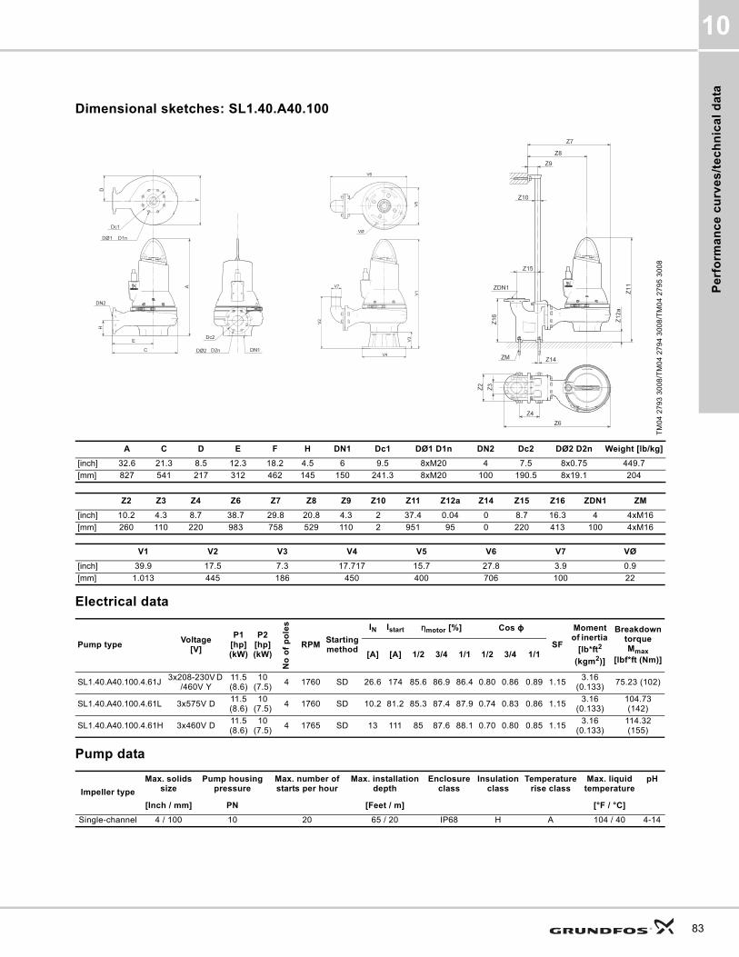
Pe
rfo
rma
nc
e c
urv
es
/te
ch
nic
al
da
ta
10
Dimensional sketches: SL1.40.A40.100
Electrical data
Pump data
TM
04
27
93
30
08
/TM
04
27
94
30
08
/TM
04
27
95
30
08
A C D E F H DN1 Dc1 DØ1 D1n DN2 Dc2 DØ2 D2n Weight [lb/kg]
[inch] 32.6 21.3 8.5 12.3 18.2 4.5 6 9.5 8xM20 4 7.5 8x0.75 449.7
[mm] 827 541 217 312 462 145 150 241.3 8xM20 100 190.5 8x19.1 204
Z2 Z3 Z4 Z6 Z7 Z8 Z9 Z10 Z11 Z12a Z14 Z15 Z16 ZDN1 ZM
[inch] 10.2 4.3 8.7 38.7 29.8 20.8 4.3 2 37.4 0.04 0 8.7 16.3 4 4xM16
[mm] 260 110 220 983 758 529 110 2 951 95 0 220 413 100 4xM16
V1 V2 V3 V4 V5 V6 V7 VØ
[inch] 39.9 17.5 7.3 17.717 15.7 27.8 3.9 0.9
[mm] 1.013 445 186 450 400 706 100 22
Pump typeVoltage
[V]
P1 [hp] (kW)
P2 [hp] (kW)
No
of
po
les
RPMStarting method
IN Istart ηmotor [%] Cos ϕ
SF
Moment of inertia
[lb*ft2
(kgm2)]
Breakdown torque Mmax
[lbf*ft (Nm)][A] [A] 1/2 3/4 1/1 1/2 3/4 1/1
SL1.40.A40.100.4.61J3x208-230V D
/460V Y11.5 (8.6)
10 (7.5)
4 1760 SD 26.6 174 85.6 86.9 86.4 0.80 0.86 0.89 1.153.16
(0.133)75.23 (102)
SL1.40.A40.100.4.61L 3x575V D11.5 (8.6)
10 (7.5)
4 1760 SD 10.2 81.2 85.3 87.4 87.9 0.74 0.83 0.86 1.153.16
(0.133)104.73 (142)
SL1.40.A40.100.4.61H 3x460V D11.5 (8.6)
10 (7.5)
4 1765 SD 13 111 85 87.6 88.1 0.70 0.80 0.85 1.153.16
(0.133)114.32 (155)
Impeller type
Max. solids size
Pump housing pressure
Max. number of starts per hour
Max. installation depth
Enclosure class
Insulation class
Temperature rise class
Max. liquid temperature
pH
[Inch / mm] PN [Feet / m] [°F / °C]
Single-channel 4 / 100 10 20 65 / 20 IP68 H A 104 / 40 4-14
83

Pe
rform
an
ce
cu
rve
s/te
ch
nic
al d
ata
10
84
SL1.40.A60
Performance curves: SL1.40.A60.55
TM
04
78
54
23
10
0 200 400 600 800 Q [US GPM]
0
5
10
15
20
25
30
35
40
45
[ft]H
0 2 4 6 8 10 12 v [ft/s]
0
10
20
30
40
50
60
70
[%]Eff
0 1 2 3 4 5 6 7 v [ft/s]
0 10 20 30 40 50 60 Q [l/s]
0
2
4
6
8
10
12
14[m]H
SL1.40.A60.55.460 Hz
HI 1.6 - 2000 level B
Eff 2
Eff 1
QH
ANSI 6 / DN 150
ANSI 8 / DN 200
0 200 400 600 800 Q [US GPM]
1
2
3
4
5
6
7
[hp]P
0 10 20 30 40 50 60 Q [l/s]
0
10
20
[ft]NPSH
1
2
3
4
5
[kW]P
0
2
4
6
[m]
NPSH
P2
P1

Pe
rfo
rma
nc
e c
urv
es
/te
ch
nic
al
da
ta
10
Dimensional sketches: SL1.40.A60.55
Electrical data
Pump data
TM
04
27
93
30
08
/TM
04
27
94
30
08
/TM
04
27
95
30
08
A C D E F H DN1 Dc1 DØ1 D1n DN2 Dc2 DØ2 D2n Weight [lb/kg]
[inch] 29.7 21.3 7.9 12.6 17.3 5.6 6 9.5 8xM20 6 9.5 8x0.88 353.8
[mm] 755 541 200 320 440 111 150 241.30 8xM20 150 241.5 8x22.2 160.5
Z2 Z3 Z4 Z6 Z7 Z8 Z9 Z10 Z11 Z12a Z14 Z15 Z16 ZDN1 ZM
[inch] 11.8 4.3 11 43 30.7 22 4.3 2 36.2 0.04 0 11 17.7 6 4xM16
[mm] 300 110 280 1.093 780 559 110 2 919 164 0 280 450 150 4xM16
V1 V2 V3 V4 V5 V6 V7 VØ
[inch] 37 21.9 7.3 17.717 15.7 31.8 5.9 0.9
[mm] 941 555 186 450 400 807 150 22
Pump typeVoltage
[V]
P1 [hp] (kW)
P2 [hp] (kW)
No of poles
RPMStarting method
IN Istart ηmotor [%] Cos ϕ
SF
Moment of inertia
[lb*ft2
(kgm2)]
Breakdown torque Mmax
[lbf*ft (Nm)][A] [A] 1/2 3/4 1/1 1/2 3/4 1/1
SL1.40.A60.55.4.61J3x208-230V D
/460V Y6.4
(4.8)5.5 (4)
4 1760 SD 16.1 79.4 79.9 83.3 83.9 0.61 0.74 0.80 1.152.18
(0.092)81.58
(110.6)
SL1.40.A60.55.4.61L 3x575V D6.4
(4.8)5.5 (4)
4 1765 SD 6.5 37.5 79.2 83.3 84.7 0.54 0.67 0.75 1.152.18
(0.092)68.59 (93)
SL1.40.A60.55.4.61H 3x460V D6.4
(4.8)5.5 (4)
4 1770 SD 8.5 51.5 78.3 82.6 84.4 0.50 0.64 0.72 1.152.18
(0.092)74.49 (101)
Impeller type
Max. solids size
Pump housing pressure
Max. number of starts per hour
Max. installation depth
Enclosure class
Insulation class
Temperature rise class
Max. liquid temperature
pH
[Inch / mm] PN [Feet / m] [°F / °C]
Single-channel 4 / 100 10 20 65 / 20 IP68 H A 104 / 40 4-14
85
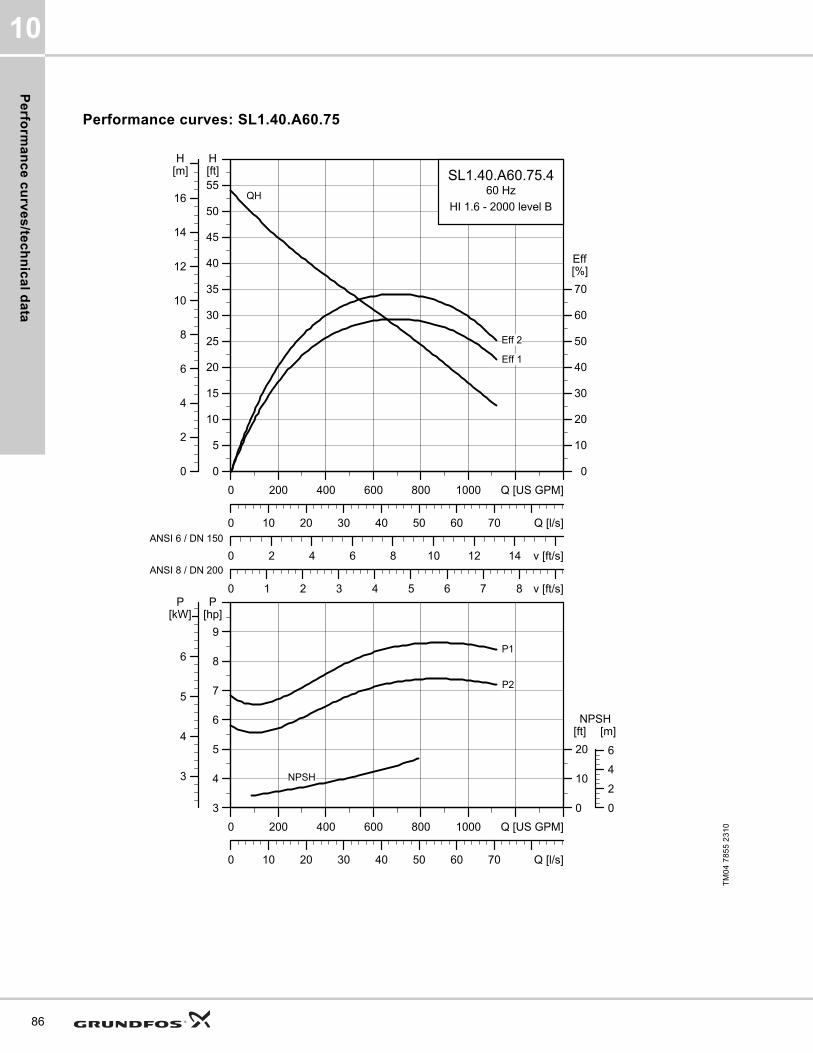
Pe
rform
an
ce
cu
rve
s/te
ch
nic
al d
ata
10
86
Performance curves: SL1.40.A60.75
TM
04
78
55
23
10
0 200 400 600 800 1000 Q [US GPM]
0
5
10
15
20
25
30
35
40
45
50
55[ft]H
0 2 4 6 8 10 12 14 v [ft/s]
0
10
20
30
40
50
60
70
[%]Eff
0 1 2 3 4 5 6 7 8 v [ft/s]
0 10 20 30 40 50 60 70 Q [l/s]
0
2
4
6
8
10
12
14
16
[m]H
SL1.40.A60.75.460 Hz
HI 1.6 - 2000 level B
Eff 2
Eff 1
QH
ANSI 6 / DN 150
ANSI 8 / DN 200
0 200 400 600 800 1000 Q [US GPM]
3
4
5
6
7
8
9
[hp]P
0 10 20 30 40 50 60 70 Q [l/s]
0
10
20
[ft]NPSH
3
4
5
6
[kW]P
0
2
4
6
[m]
NPSH
P2
P1

Pe
rfo
rma
nc
e c
urv
es
/te
ch
nic
al
da
ta
10
Dimensional sketches: SL1.40.A60.75
Electrical data
Pump data
TM
04
27
93
30
08
/TM
04
27
94
30
08
/TM
04
27
95
30
08
A C D E F H DN1 Dc1 DØ1 D1n DN2 Dc2 DØ2 D2n Weight [lb/kg]
[inch] 30 21.3 7.9 12.6 17.3 5.6 6 9.5 8xM20 6 9.5 8x0.88 369.1
[mm] 762 541 200 320 440 111 150 241.30 8xM20 150 241.5 8x22.2 167.4
Z2 Z3 Z4 Z6 Z7 Z8 Z9 Z10 Z11 Z12a Z14 Z15 Z16 ZDN1 ZM
[inch] 11.8 4.3 11 43 30.7 22 4.3 2 36.5 0.04 0 11 17.7 6 4xM16
[mm] 300 110 280 1.093 780 559 110 2 926 164 0 280 450 150 4xM16
V1 V2 V3 V4 V5 V6 V7 VØ
[inch] 37.3 21.9 7.3 17.717 15.7 31.8 5.9 0.9
[mm] 948 555 186 450 400 807 150 22
Pump typeVoltage
[V]
P1 [hp] (kW)
P2 [hp] (kW)
No of poles
RPMStarting method
IN Istart ηmotor [%] Cos ϕ
SF
Moment of inertia
[lb*ft2
(kgm2)]
Breakdown torque Mmax
[lbf*ft (Nm)][A] [A] 1/2 3/4 1/1 1/2 3/4 1/1
SL1.40.A60.75.4.61J3x208-230V D
/460V Y8.6
(6.4)7.5
(5.5)4 1760 SD 20 126 83.2 85.6 85.8 0.77 0.84 0.87 1.15
2.69 (0.11356)
90.41 (122.58)
SL1.40.A60.75.4.61L 3x57 5V D8.6
(6.4)7.5
(5.5)4 1765 SD 7.8 59.3 83.5 86.6 87.3 0.69 0.79 0.84 1.15
2.69 (0.11356)
75.97 (103)
SL1.40.A60.75.4.61H 3x460V D8.6
(6.4)7.5
(5.5)4 1770 SD 10 81.4 82.9 86.3 87.2 0.65 0.75 0.81 1.15
2.69 (0.11356)
83.34 (113)
Impeller type
Max. solids size
Pump housing pressure
Max. number of starts per hour
Max. installation depth
Enclosure class
Insulation class
Temperature rise class
Max. liquid temperature
pH
[Inch / mm] PN [Feet / m] [°F / °C]
Single-channel 4 / 100 10 20 65 / 20 IP68 H A 104 / 40 4-14
87
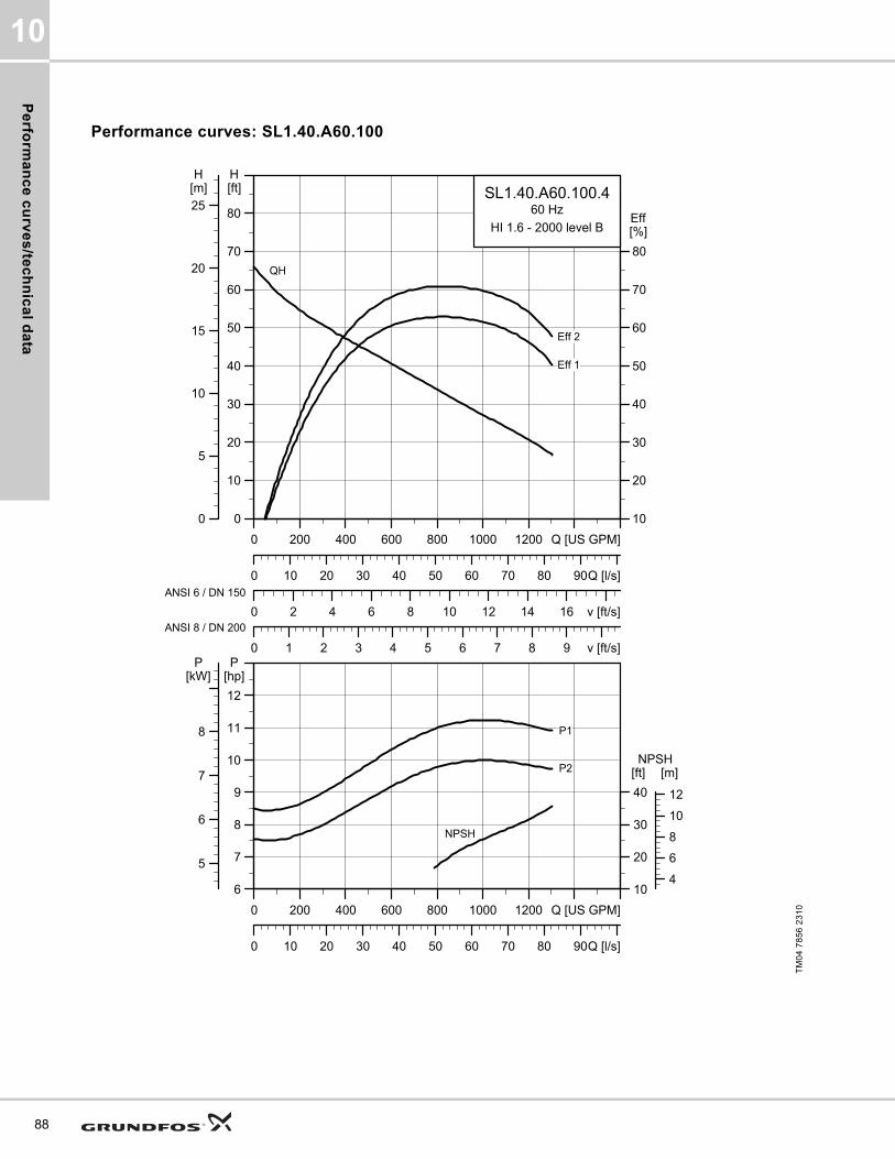
Pe
rform
an
ce
cu
rve
s/te
ch
nic
al d
ata
10
88
Performance curves: SL1.40.A60.100
TM
04
78
56
23
10
0 200 400 600 800 1000 1200 Q [US GPM]
0
10
20
30
40
50
60
70
80
[ft]H
0 2 4 6 8 10 12 14 16 v [ft/s]
10
20
30
40
50
60
70
80
[%]Eff
0 1 2 3 4 5 6 7 8 9 v [ft/s]
0 10 20 30 40 50 60 70 80 90Q [l/s]
0
5
10
15
20
25[m]H
SL1.40.A60.100.460 Hz
HI 1.6 - 2000 level B
Eff 2
Eff 1
QH
ANSI 6 / DN 150
ANSI 8 / DN 200
0 200 400 600 800 1000 1200 Q [US GPM]
6
7
8
9
10
11
12
[hp]P
0 10 20 30 40 50 60 70 80 90Q [l/s]
10
20
30
40
[ft]NPSH
5
6
7
8
[kW]P
4
6
8
10
12
[m]
NPSH
P2
P1

Pe
rfo
rma
nc
e c
urv
es
/te
ch
nic
al
da
ta
10
Dimensional sketches: SL1.40.A60.100
Electrical data
Pump data
TM
04
27
93
30
08
/TM
04
27
94
30
08
/TM
04
27
95
30
08
A C D E F H DN1 Dc1 DØ1 D1n DN2 Dc2 DØ2 D2n Weight [lb/kg]
[inch] 32.6 21.3 8.5 12 18.6 5.6 6 9.5 8xM20 6 9.5 8x0.88 454.4
[mm] 827 541 217 306 472 111 150 241.30 8xM20 150 241.5 8x22.2 206.1
Z2 Z3 Z4 Z6 Z7 Z8 Z9 Z10 Z11 Z12a Z14 Z15 Z16 ZDN1 ZM
[inch] 11.8 4.3 11 43 30.7 21.5 4.3 2 39 0.04 0 11 17.7 6 4xM16
[mm] 300 110 280 1.093 780 545 110 2 991 164 0 280 450 150 4xM16
V1 V2 V3 V4 V5 V6 V7 VØ
[inch] 39.9 21.9 7.3 17.717 15.7 31.6 5.9 0.9
[mm] 1.013 555 186 450 400 803 150 22
Pump typeVoltage
[V]
P1 [hp] (kW)
P2 [hp] (kW)
No
of
po
les
RPMStarting method
IN Istart ηmotor [%] Cos ϕ
SF
Moment of inertia
[lb*ft2
(kgm2)]
Breakdown torque Mmax
[lbf*ft (Nm)][A] [A] 1/2 3/4 1/1 1/2 3/4 1/1
SL1.40.A60.100.4.61J3x208-230V D
/460V Y11.5 (8.6)
10 (7.5)
4 1760 SD 26.6 174 85.6 86.9 86.4 0.80 0.86 0.89 1.153.16
(0.133)75.23 (102)
SL1.40.A60.100.4.61L 3x575V D11.5 (8.6)
10 (7.5)
4 1760 SD 10.2 81.2 85.3 87.4 87.9 0.74 0.83 0.86 1.153.16
(0.133)104.73 (142)
SL1.40.A60.100.4.61H 3x460V D11.5 (8.6)
10 (7.5)
4 1765 SD 13 111 85 87.6 88.1 0.70 0.80 0.85 1.153.16
(0.133)114.32 (155)
Impeller type
Max. solids size
Pump housing pressure
Max. number of starts per hour
Max. installation depth
Enclosure class
Insulation class
Temperature rise class
Max. liquid temperature
pH
[Inch / mm] PN [Feet / m] [°F / °C]
Single-channel 4 / 100 10 20 65 / 20 IP68 H A 104 / 40 4-14
89
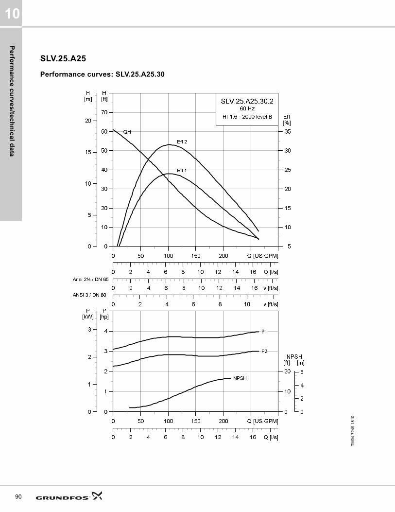
Pe
rform
an
ce
cu
rve
s/te
ch
nic
al d
ata
10
90
SLV.25.A25
Performance curves: SLV.25.A25.30
TM
04
72
49
18
10
0 50 100 150 200 Q [US GPM]
0
10
20
30
40
50
60
70
[ft]H
0 2 4 6 8 10 12 14 16 v [ft/s]
5
10
15
20
25
30
35
[%]Eff
0 2 4 6 8 10 v [ft/s]
0 2 4 6 8 10 12 14 16 Q [l/s]
0
5
10
15
20
[m]H
SLV.25.A25.30.2
60 Hz
HI 1.6 - 2000 level B
Eff 2
Eff 1
QH
Ansi 2½ / DN 65
ANSI 3 / DN 80
0 50 100 150 200 Q [US GPM]
0
1
2
3
4
[hp]P
0 2 4 6 8 10 12 14 16 Q [l/s]
0
10
20
[ft]NPSH
0
1
2
3
[kW]P
0
2
4
6
[m]
P2
P1
NPSH

Pe
rfo
rma
nc
e c
urv
es
/te
ch
nic
al
da
ta
10
Dimensional sketches: SLV.25.A25.30
Electrical data
Pump data
TM
04
27
93
30
08
/TM
04
27
94
30
08
/TM
04
27
95
30
08
A C D E F H DN1 Dc1 DØ1 D1n DN2 Dc2 DØ2 D2n Weight [lb/kg]
[inch] 26.9 15.6 6.7 9.7 12.6 4 3 6 8xM16 2.5 5.5 4 x 0.75 190.5
[mm] 684 396 171 246 321 102 80 152.4 8xM16 65 139.7 4 x 19.1 86.4
Z2 Z3 Z4 Z6 Z7 Z8 Z9 Z10 Z11 Z12a Z14 Z15 Z16 ZDN1 ZM
[inch] 8.3 3.7 5.5 28.7 21.4 15.5 3.2 1.5 29.4 0.03 0.040 6.9 10.5 2.5 4xM16
[mm] 210 95 140 730 543 394 81 1.5 747 64 1 175 266 65 4xM16
V1 V2 V3 V4 V5 V6 V7 VØ
[inch] 32 14.7 5 12.990 11 20.6 2.6 0.7
[mm] 812 372 128 330 280 524 65 18
Pump typeVoltage
[V]
P1 [hp] (kW)
P2 [hp] (kW)
No of poles
RPMStarting method
IN Istart ηmotor [%] Cos ϕ
SF
Moment of inertia
[lb*ft2
(kgm2)]
Breakdown torque Mmax
[lbf*ft (Nm)][A] [A] 1/2 3/4 1/1 1/2 3/4 1/1
SLV.25.A25.30.2.61J3x208-230V D
/460V Y3.9
(2.9)3
(2.2)2 3480 SD 8.8 68.7 67.7 72.8 74.3 0.85 0.89 0.91 1.15
0.13 (0.0054)
14.01 (19)
SLV.25.A25.30.2.61H 3x460V D3.9
(2.9)3
(2.2)2 3520 SD 4.3 44.0 66.7 73.3 76.1 0.77 0.85 0.88 1.15
0.13 (0.0054)
18.44 (25)
SLV.25.A25.30.2.61L 3x575V D3.9
(2.9)3
(2.2)2 3510 SD 3.2 32.1 67.7 73 75.8 0.81 0.87 0.89 1.15
0.13 (0.0054)
16.96 (23)
Impeller type
Max. solids size
Pump housing pressure
Max. number of starts per hour
Max. installation depth
Enclosure class
Insulation class
Temperature rise class
Max. liquid temperature
pH
[Inch / mm] PN [Feet / m] [°F / °C]
SuperVortex 2.5 / 65 10 20 65 / 20 IP68 H A 104 / 40 4-14
91
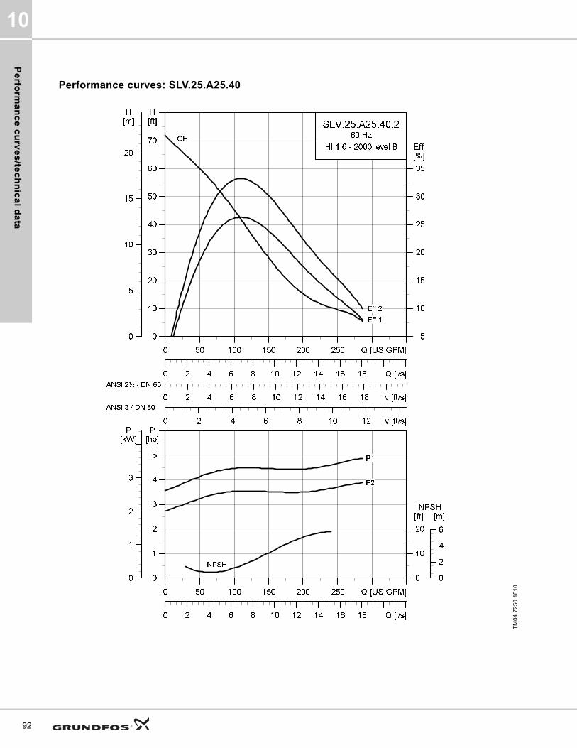
Pe
rform
an
ce
cu
rve
s/te
ch
nic
al d
ata
10
92
Performance curves: SLV.25.A25.40
TM
04
72
50
18
10
0 50 100 150 200 250 Q [US GPM]
0
10
20
30
40
50
60
70
[ft]H
0 2 4 6 8 10 12 14 16 18 v [ft/s]
5
10
15
20
25
30
35
[%]Eff
0 2 4 6 8 10 12 v [ft/s]
0 2 4 6 8 10 12 14 16 18 Q [l/s]
0
5
10
15
20
[m]H
SLV.25.A25.40.2
60 Hz
HI 1.6 - 2000 level B
Eff 2
Eff 1
QH
ANSI 2½ / DN 65
ANSI 3 / DN 80
0 50 100 150 200 250 Q [US GPM]
0
1
2
3
4
5
[hp]P
0 2 4 6 8 10 12 14 16 18 Q [l/s]
0
10
20
[ft]NPSH
0
2
4
6
[m]
0
1
2
3
[kW]P
NPSH
P2
P1

Pe
rfo
rma
nc
e c
urv
es
/te
ch
nic
al
da
ta
10
Dimensional sketches: SLV.25.A25.40
Electrical data
Pump data
TM
04
27
93
30
08
/TM
04
27
94
30
08
/TM
04
27
95
30
08
A C D E F H DN1 Dc1 DØ1 D1n DN2 Dc2 DØ2 D2n Weight [lb/kg]
[inch] 26.9 15.6 6.7 9.7 12.6 4 3 6 8xM16 2.5 5.5 4x0.75 197.3
[mm] 684 396 171 246 321 102 80 152.4 8xM16 65 139.7 4x19.1 89.5
Z2 Z3 Z4 Z6 Z7 Z8 Z9 Z10 Z11 Z12a Z14 Z15 Z16 ZDN1 ZM
[inch] 8.3 3.7 5.5 28.7 21.4 15.5 3.2 1.5 29.4 0.03 0.040 6.9 10.5 2.5 4xM16
[mm] 210 95 140 730 543 394 81 1.5 747 64 1 175 266 65 4xM16
V1 V2 V3 V4 V5 V6 V7 VØ
[inch] 32 14.7 5 12.990 11 20.6 2.6 0.7
[mm] 812 372 128 330 280 524 65 18
Pump typeVoltage
[V]
P1 [hp] (kW)
P2 [hp] (kW)
No of poles
RPMStarting method
IN Istart ηmotor [%] Cos ϕ
SF
Moment of inertia
[lb*ft2
(kgm2)]
Breakdown torque Mmax
[lbf*ft (Nm)][A] [A] 1/2 3/4 1/1 1/2 3/4 1/1
SLV.25.A25.40.2.61J3x208-230V D
/460V Y5.1
(3.8)4 (3) 2 3510 SD 11.6 99.5 72.9 77.2 78.4 0.79 0.86 0.89 1.15
0.16 (0.0067)
22.86 (31)
SLV.25.A25.40.2.61L 3x575V D5.1
(3.8)4 (3) 2 3510 SD 4.5 47.9 72.9 77.8 79.6 0.74 0.82 0.87 1.15
0.16 (0.0067)
28.03 (38)
SLV.25.A25.40.2.61H 3x460V D5.1
(3.8)4 (3) 2 3510 SD 5.9 63.5 72.5 77.4 79.7 0.66 0.77 0.83 1.15
0.16 (0.0067)
29.5 (40)
Impeller type
Max. solids size
Pump housing pressure
Max. number of starts per hour
Max. installation depth
Enclosure class
Insulation class
Temperature rise class
Max. liquid temperature
pH
[Inch / mm] PN [Feet / m] [°F / °C]
SuperVortex 2.5 / 65 10 20 65 / 20 IP68 H A 104 / 40 4-14
93

Pe
rform
an
ce
cu
rve
s/te
ch
nic
al d
ata
10
94
Performance curves: SLV.25.A25.55
TM
04
72
51
18
10
0 40 80 120 160 Q [US GPM]
0
10
20
30
40
50
60
70
80
90
100
[ft]H
0 2 4 6 8 10 12 v [ft/s]
0
5
10
15
20
25
30
35
40
[%]Eff
0 2 4 6 8 v [ft/s]
0 2 4 6 8 10 12 Q [l/s]
0
5
10
15
20
25
30
[m]H
SLV.25.A25.55.2
60 Hz
HI 1.6 - 2000 level B
Eff 2
Eff 1
QH
ANSI 2½ / DN 65
ANSI 3 / DN 80
0 40 80 120 160 Q [US GPM]
0
1
2
3
4
5
6
7
[hp]P
0 2 4 6 8 10 12 Q [l/s]
0
5
10
15
[ft]NPSH
0
1
2
3
4
5
[kW]P
0
2
4
[m]
NPSH
P2
P1

Pe
rfo
rma
nc
e c
urv
es
/te
ch
nic
al
da
ta
10
Dimensional sketches: SLV.25.A25.55
Electrical data
Pump data
TM
04
27
93
30
08
/TM
04
27
94
30
08
/TM
04
27
95
30
08
A C D E F H DN1 Dc1 DØ1 D1n DN2 Dc2 DØ2 D2n Weight [lb/kg]
[inch] 28.3 18 7.9 10.9 15 4.2 3 6 8xM16 2.5 5.5 4x0.75 257.3
[mm] 718 456 200 276 380 106 80 152.4 8xM16 65 139.7 4x19.1 116.7
Z2 Z3 Z4 Z6 Z7 Z8 Z9 Z10 Z11 Z12a Z14 Z15 Z16 ZDN1 ZM
[inch] 8.3 3.7 5.5 29.9 23.8 16.7 3.2 1.5 30.6 0.03 0.040 6.9 10.5 2.5 4xM16
[mm] 210 95 140 760 604 424 81 1.5 778 60 1 175 266 65 4xM16
V1 V2 V3 V4 V5 V6 V7 VØ
[inch] 33.3 14.8 5 12.990 11 22.4 2.6 0.7
[mm] 846 376 128 330 280 568 65 18
Pump typeVoltage
[V]
P1 [hp] (kW)
P2 [hp] (kW)
No of poles
RPMStarting method
IN Istart ηmotor [%] Cos ϕ
SF
Moment of inertia
[lb*ft2
(kgm2)]
Breakdown torque Mmax
[lbf*ft (Nm)][A] [A] 1/2 3/4 1/1 1/2 3/4 1/1
SLV.25.A25.55.2.61J3x208-230V D
/460V Y6.6
(4.9)5.5 (4)
2 3530 SD 14.8 152 75 79.9 81.7 0.78 0.86 0.90 1.150.38
(0.0159)53.51 (72.5)
SLV.25.A25.55.2.61L 3x575V D6.6
(4.9)5.5 (4)
2 3535 SD 5.8 70.8 74.1 79.6 82 0.71 0.82 0.87 1.150.38
(0.0159)44.99 (61)
SLV.25.A25.55.2.61H 3x460V D6.6
(4.9)5.5 (4)
2 3540 SD 7.4 96.8 73.6 79.2 82 0.68 0.80 0.85 1.150.38
(0.0159)37.62 (51)
Impeller type
Max. solids size
Pump housing pressure
Max. number of starts per hour
Max. installation depth
Enclosure class
Insulation class
Temperature rise class
Max. liquid temperature
pH
[Inch / mm] PN [Feet / m] [°F / °C]
SuperVortex 2.5 / 65 10 20 65 / 20 IP68 H A 104 / 40 4-14
95

Pe
rform
an
ce
cu
rve
s/te
ch
nic
al d
ata
10
96
SLV.25.A30
Performance curves: SLV.25.A30.30
TM
04
72
52
18
10
0 50 100 150 200 250 Q [US GPM]
0
5
10
15
20
25
30
35
40
45
50
55
60
[ft]H
0 2 4 6 8 10 12 v [ft/s]
0
4
8
12
16
20
24
28
32
[%]Eff
0 2 4 6 8 v [ft/s]
0 2 4 6 8 10 12 14 16 18 Q [l/s]
0
2
4
6
8
10
12
14
16
18
[m]H
SLV.25.A30.30.2
60 Hz
HI 1.6 - 2000 level B
Eff 2
Eff 1
QH
ANSI 3 / DN 80
ANSI 4 / DN 100
0 50 100 150 200 250 Q [US GPM]
0
1
2
3
4
5
[hp]P
0 2 4 6 8 10 12 14 16 18 Q [l/s]
0
10
20
30
[ft]NPSH
0
1
2
3
[kW]P
0
2
4
6
8
[m]
NPSH
P2
P1

Pe
rfo
rma
nc
e c
urv
es
/te
ch
nic
al
da
ta
10
Dimensional sketches: SLV.25.A30.30
Electrical data
Pump data
TM
04
27
93
30
08
/TM
04
27
94
30
08
/TM
04
27
95
30
08
A C D E F H DN1 Dc1 DØ1 D1n DN2 Dc2 DØ2 D2n Weight [lb/kg]
[inch] 27 15.6 6.7 9.7 12.6 4.1 3 6 8xM16 3 6 8x0.75 192.9
[mm] 685 397 171 247 321 103 80 152.4 8xM16 80 152.4 8x19.1 87.5
Z2 Z3 Z4 Z6 Z7 Z8 Z9 Z10 Z11 Z12a Z14 Z15 Z16 ZDN1 ZM
[inch] 8.7 3.7 6.3 29.5 21.9 16.1 3.2 1.5 30.8 0.03 0.510 6.7 13.6 3 4xM16
[mm] 220 95 160 750 557 408 81 1.5 782 97 13 171 345 80 4xM16
V1 V2 V3 V4 V5 V6 V7 VØ
[inch] 32 14.7 5 12.990 11 20.9 3.2 0.7
[mm] 813 373 128 330 280 530 80 18
Pump typeVoltage
[V]
P1 [hp] (kW)
P2 [hp] (kW)
No of poles
RPMStarting method
IN Istart ηmotor [%] Cos ϕ
SF
Moment of inertia
[lb*ft2
(kgm2)]
Breakdown torque Mmax
[lbf*ft (Nm)][A] [A] 1/2 3/4 1/1 1/2 3/4 1/1
SLV.25.A30.30.2.61J3x208-230V D
/ 460V Y3.9
(2.9)3
(2.2)2 3480 SD 8.8 68.7 67.7 72.8 74.3 0.85 0.89 0.91 1.15
0.13 (0.0054)
14.01 (19)
SLV.25.A30.30.2.61H 3x460V D3.9
(2.9)3
(2.2)2 3520 SD 4.3 44 66.7 73.3 76.1 0.77 0.85 0.88 1.15
0.13 (0.0054)
18.44 (25)
SLV.25.A30.30.2.61L 3x575V D3.9
(2.9)3
(2.2)2 3510 SD 3.2 32.1 67.7 73 75.8 0.81 0.87 0.89 1.15
0.13 (0.0054)
16.96 (23)
Impeller type
Max. solids size
Pump housing pressure
Max. number of starts per hour
Max. installation depth
Enclosure class
Insulation class
Temperature rise class
Max. liquid temperature
pH
[Inch / mm] PN [Feet / m] [°F / °C]
SuperVortex 2.5 / 65 10 20 65 / 20 IP68 H A 104 / 40 4-14
97

Pe
rform
an
ce
cu
rve
s/te
ch
nic
al d
ata
10
98
Performance curves: SLV.25.A30.40
TM
04
72
53
18
10
0 50 100 150 200 250 Q [US GPM]
0
10
20
30
40
50
60
70
80
[ft]H
0 2 4 6 8 10 12 v [ft/s]
0
5
10
15
20
25
30
35
[%]Eff
0 2 4 6 8 v [ft/s]
0 2 4 6 8 10 12 14 16 18 Q [l/s]
0
5
10
15
20
25
[m]H
SLV.25.A30.40.2
60 Hz
HI 1.6 - 2000 level B
Eff 2
Eff 1
QH
ANSI 3 / DN 80
ANSI 4 / DN 100
0 50 100 150 200 250 Q [US GPM]
0
1
2
3
4
5
[hp]P
0 2 4 6 8 10 12 14 16 18 Q [l/s]
0
10
20
[ft]NPSH
0
1
2
3
[kW]P
0
2
4
6
[m]
NPSH
P2
P1

Pe
rfo
rma
nc
e c
urv
es
/te
ch
nic
al
da
ta
10
Dimensional sketches: SLV.25.A30.40
Electrical data
Pump data
TM
04
27
93
30
08
/TM
04
27
94
30
08
/TM
04
27
95
30
08
A C D E F H DN1 Dc1 DØ1 D1n DN2 Dc2 DØ2 D2n Weight [lb/kg]
[inch] 27 15.6 6.7 9.7 12.6 4.1 3 6 8xM16 3 6 8 x 0.75 199.7
[mm] 685 397 171 247 321 103 80 152.4 8xM16 80 152.4 8 x 19.1 90.6
Z2 Z3 Z4 Z6 Z7 Z8 Z9 Z10 Z11 Z12a Z14 Z15 Z16 ZDN1 ZM
[inch] 8.7 3.7 6.3 29.5 21.9 16.1 3.2 1.5 30.8 0.03 0.510 6.7 13.6 3 4xM16
[mm] 220 95 160 750 557 408 81 1.5 782 97 13 171 345 80 4xM16
V1 V2 V3 V4 V5 V6 V7 VØ
[inch] 32 14.7 5 12.990 11 20.9 3.2 0.7
[mm] 813 373 128 330 280 530 80 18
Pump typeVoltage
[V]
P1 [hp] (kW)
P2 [hp] (kW)
No of poles
RPMStarting method
IN Istart ηmotor [%] Cos ϕ
SF
Moment of inertia
[lb*ft2
(kgm2)]
Breakdown torque Mmax
[lbf*ft (Nm)][A] [A] 1/2 3/4 1/1 1/2 3/4 1/1
SLV.25.A30.40.2.61J3x208-230V D /
460V Y5.1
(3.8)4 (3) 2 3510 SD 11.6 99.5 72.9 77.2 78.4 0.79 0.86 0.89 1.15
0.16 (0.0067)
22.86 (31)
SLV.25.A30.40.2.61L 3x575V D5.1
(3.8)4 (3) 2 3510 SD 4.5 47.9 72.9 77.8 79.6 0.74 0.82 0.87 1.15
0.16 (0.0067)
28.03 (38)
SLV.25.A30.40.2.61H 3x460V D5.1
(3.8)4 (3) 2 3510 SD 5.9 63.5 72.5 77.4 79.7 0.66 0.77 0.83 1.15
0.16 (0.0067)
29.5 (40)
Impeller type
Max. solids size
Pump housing pressure
Max. number of starts per hour
Max. installation depth
Enclosure class
Insulation class
Temperature rise class
Max. liquid temperature
pH
[Inch / mm] PN [Feet / m] [°F / °C]
SuperVortex 2.5 / 65 10 20 65 / 20 IP68 H A 104 / 40 4-14
99

Pe
rform
an
ce
cu
rve
s/te
ch
nic
al d
ata
10
100
Performance curves: SLV.25.A30.55
TM
04
72
54
18
10
0 50 100 150 200 250 Q [US GPM]
0
10
20
30
40
50
60
70
80
90
[ft]H
0 2 4 6 8 10 12 v [ft/s]
0
5
10
15
20
25
30
35
[%]Eff
0 2 4 6 8 v [ft/s]
0 2 4 6 8 10 12 14 16 18 Q [l/s]
0
5
10
15
20
25
[m]H
SLV.25.A30.55.2
60 Hz
HI 1.6 - 2000 level B
Eff 2
Eff 1
QH
ANSI 3 / DN 80
ANSI 4 / DN 100
0 50 100 150 200 250 Q [US GPM]
1
2
3
4
5
6
7
[hp]P
0 2 4 6 8 10 12 14 16 18 Q [l/s]
0
10
20
30
[ft]NPSH
0
2
4
6
8
[m]
1
2
3
4
5
[kW]P
NPSH
P2
P1

Pe
rfo
rma
nc
e c
urv
es
/te
ch
nic
al
da
ta
10
Dimensional sketches: SLV.25.A30.55
Electrical data
Pump data
TM
04
27
93
30
08
/TM
04
27
94
30
08
/TM
04
27
95
30
08
A C D E F H DN1 Dc1 DØ1 D1n DN2 Dc2 DØ2 D2n Weight [lb/kg]
[inch] 28.3 17.9 7.9 10.9 14.9 4.2 3 6 8xM16 3 6 8x0.75 258.4
[mm] 718 455 200 276 379 106 80 152.4 8xM16 80 152.4 8x19.1 117.2
Z2 Z3 Z4 Z6 Z7 Z8 Z9 Z10 Z11 Z12a Z14 Z15 Z16 ZDN1 ZM
[inch] 8.7 3.7 6.3 31.8 24.3 17.2 3.2 1.5 32 0.03 0.510 6.7 13.6 3 4xM16
[mm] 220 95 160 808 616 437 81 1.5 812 94 13 171 345 80 4xM16
V1 V2 V3 V4 V5 V6 V7 VØ
[inch] 33.3 14.8 5 12.990 11 22.6 3.2 0.7
[mm] 846 376 128 330 280 573 80 18
Pump typeVoltage
[V]
P1 [hp] (kW)
P2 [hp] (kW)
No of poles
RPMStarting method
IN Istart ηmotor [%] Cos ϕ
SF
Moment of
inertia
[lb*ft2
(kgm2)]
Breakdown torque Mmax [lbf*ft (Nm)][A] [A] 1/2 3/4 1/1 1/2 3/4 1/1
SLV.25.A30.55.2.61J3x208-230V D
/ 460V Y6.6
(4.9)5.5 (4)
2 3530 SD 14.8 152 75 79.9 81.7 0.78 0.86 0.90 1.150.35
(0.0149)53.51
(72.54741459)
SLV.25.A30.55.2.61L 3x575V D6.6
(4.9)5.5 (4)
2 3535 SD 5.8 70.8 74.1 79.6 82 0.71 0.82 0.87 1.150.35
(0.0149)44.99 (61)
SLV.25.A30.55.2.61H 3x460V D6.6
(4.9)5.5 (4)
2 3540 SD 7.4 96.8 73.6 79.2 82 0.68 0.80 0.85 1.150.35
(0.0149)37.62 (51)
Impeller type
Max. solids size
Pump housing pressure
Max. number of starts per hour
Max. installation depth
Enclosure class
Insulation class
Temperature rise class
Max. liquid temperature
pH
[Inch / mm] PN [Feet / m] [°F / °C]
SuperVortex 2.5 / 65 10 20 65 / 20 IP68 H A 104 / 40 4-14
101
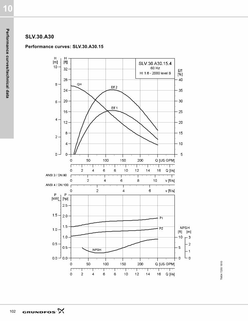
Pe
rform
an
ce
cu
rve
s/te
ch
nic
al d
ata
10
102
SLV.30.A30
Performance curves: SLV.30.A30.15
TM
04
72
55
18
10
0 50 100 150 200 Q [US GPM]
0
4
8
12
16
20
24
28
32
[ft]H
0 2 4 6 8 10 v [ft/s]
5
10
15
20
25
30
35
40
[%]Eff
0 2 4 6 v [ft/s]
0 2 4 6 8 10 12 14 16 Q [l/s]
0
2
4
6
8
10
[m]H
SLV.30.A30.15.4
60 Hz
HI 1.6 - 2000 level B
Eff 2
Eff 1
QH
ANSI 3 / DN 80
ANSI 4 / DN 100
0 50 100 150 200 Q [US GPM]
0.0
0.5
1.0
1.5
2.0
2.5
[hp]P
0 2 4 6 8 10 12 14 16 Q [l/s]
0
5
10
[ft]NPSH
0.0
0.5
1.0
1.5
[kW]P
0
1
2
3
[m]
NPSH
P2
P1

Pe
rfo
rma
nc
e c
urv
es
/te
ch
nic
al
da
ta
10
Dimensional sketches: SLV.30.A30.15
Electrical data
Pump data
TM
04
27
93
30
08
/TM
04
27
94
30
08
/TM
04
27
95
30
08
A C D E F H DN1 Dc1 DØ1 D1n DN2 Dc2 DØ2 D2n Weight [lb/kg]
[inch] 28 16.1 6.7 9.5 13.4 4.3 3 6 8xM16 3 6 8x0.75 205.5
[mm] 711 409 171 241 339 109 80 152.4 8xM16 80 152.4 8x19.1 93.2
Z2 Z3 Z4 Z6 Z7 Z8 Z9 Z10 Z11 Z12a Z14 Z15 Z16 ZDN1 ZM
[inch] 8.7 3.7 6.3 30 22.4 15.8 3.2 1.5 31.6 0.03 0.510 6.7 13.6 3 4xM16
[mm] 220 95 160 762 569 402 81 1.5 802 91 13 171 345 80 4xM16
V1 V2 V3 V4 V5 V6 V7 VØ
[inch] 33 14.9 5 12.99 11 20.8 3.2 0.7
[mm] 839 379 128 330 280 527 80 18
Pump typeVoltage
[V]
P1 [hp] (kW)
P2 [hp] (kW)
No of poles
RPMStarting method
IN Istart ηmotor [%] Cos ϕ
SF
Moment of inertia
[lb*ft2
(kgm2)]
Breakdown torque Mmax
[lbf*ft (Nm)][A] [A] 1/2 3/4 1/1 1/2 3/4 1/1
SLV.30.A30.15.4.61J3x208-230V D
/ 460V Y2
(1.5)1.5
(1.1)4 1750 SD 5.1 31.9 66.2 71.5 73.9 0.65 0.74 0.80 1.15
0.33 (0.014)
14.01 (19)
SLV.30.A30.15.4.60J3x208-230V D
/ 460V Y2
(1.5)1.5
(1.1)4 1750 DOL 5.1 31.9 66.2 71.5 73.9 0.65 0.74 0.80 1.15
0.33 (0.014)
14.01 (19)
SLV.30.A30.15.4.60L 3x575V D2
(1.5)1.5
(1.1)4 1755 DOL 2 14.9 65 71.4 74.5 0.59 0.69 0.75 1.15
0.33 (0.014)
16.96 (23)
SLV.30.A30.15.4.61L 3x575V D2
(1.5)1.5
(1.1)4 1755 SD 2 14.9 65 71.4 74.5 0.59 0.69 0.75 1.15
0.33 (0.014)
16.96 (23)
Impeller type
Max. solids size
Pump housing pressure
Max. number of starts per hour
Max. installation depth
Enclosure class
Insulation class
Temperature rise class
Max. liquid temperature
pH
[Inch / mm] PN [Feet / m] [°F / °C]
SuperVortex 3 / 80 10 20 65 / 20 IP68 H A 104 / 40 4-14
103

Pe
rform
an
ce
cu
rve
s/te
ch
nic
al d
ata
10
104
Performance curves: SLV.30.A30.18
TM
04
72
56
18
10
0 50 100 150 200 Q [US GPM]
0
4
8
12
16
20
24
28
32
[ft]H
0 2 4 6 8 10 v [ft/s]
5
10
15
20
25
30
35
40
[%]Eff
0 2 4 6 v [ft/s]
0 2 4 6 8 10 12 14 16 Q [l/s]
0
2
4
6
8
10
[m]H
SLV.30.A30.18.4
60 Hz
HI 1.6 - 2000 level B
Eff 2
Eff 1
QH
ANSI 3 / DN 80
ANSI 4 / DN 100
0 50 100 150 200 Q [US GPM]
0.0
0.5
1.0
1.5
2.0
2.5
[hp]P
0 2 4 6 8 10 12 14 16 Q [l/s]
0
5
10
[ft]NPSH
0.0
0.5
1.0
1.5
[kW]p
0
1
2
3
[m]
NPSH
P2
P1

Pe
rfo
rma
nc
e c
urv
es
/te
ch
nic
al
da
ta
10
Dimensional sketches: SLV.30.A30.18
Electrical data
Pump data
TM
04
27
93
30
08
/TM
04
27
94
30
08
/TM
04
27
95
30
08
A C D E F H DN1 Dc1 DØ1 D1n DN2 Dc2 DØ2 D2n Weight [lb/kg]
[inch] 28 16.1 6.7 9.5 13.4 4.3 3 6 8xM16 3 6 8 x 0.75 206.4
[mm] 711 409 171 241 339 109 80 152.4 8xM16 80 152.4 8 x 19.1 93.6
Z2 Z3 Z4 Z6 Z7 Z8 Z9 Z10 Z11 Z12a Z14 Z15 Z16 ZDN1 ZM
[inch] 8.7 3.7 6.3 30 22.4 15.8 3.2 1.5 31.6 0.03 0.510 6.7 13.6 3 4xM16
[mm] 220 95 160 762 569 402 81 1.5 802 91 13 171 345 80 4xM16
V1 V2 V3 V4 V5 V6 V7 VØ
[inch] 33 14.9 5 12.990 11 20.8 3.2 0.7
[mm] 839 379 128 330 280 527 80 18
Pump typeVoltage
[V]
P1 [hp] (kW)
P2 [hp] (kW)
No of poles
RPMStarting method
IN Istart ηmotor [%] Cos ϕ
SF
Moment of inertia
[lb*ft2
(kgm2)]
Breakdown torque Mmax
[lbf*ft (Nm)][A] [A] 1/2 3/4 1/1 1/2 3/4 1/1
SLV.30.A30.18.4.61J3x208-230V D
/ 460V Y2.5
(1.9)2
(1.5)4 1750 SD 6.6 42.5 69.6 74.4 76.2 0.65 0.74 0.80 1.15
0.37 (0.0155)
19.18 (26)
SLV.30.A30.18.4.60J3x208-230V D
/ 460V Y2.5
(1.9)2
(1.5)4 1750 DOL 6.6 42.5 69.6 74.4 76.2 0.65 0.74 0.80 1.15
0.37 (0.0155)
19.18 (26)
SLV.30.A30.18.4.60L 3x575V D2.5
(1.9)2
(1.5)4 1750 DOL 2.6 20 68.7 74.4 77 0.59 0.69 0.76 1.15
0.37 (0.0155)
22.86 (31)
SLV.30.A30.18.4.61L 3x575V D2.5
(1.9)2
(1.5)4 1750 SD 2.6 20 68.7 74.4 77 0.59 0.69 0.76 1.15
0.37 (0.0155)
22.86 (31)
Impeller type
Max. solids size
Pump housing pressure
Max. number of starts per hour
Max. installation depth
Enclosure class
Insulation class
Temperature rise class
Max. liquid temperature
pH
[Inch / mm] PN [Feet / m] [°F / °C]
SuperVortex 3 / 80 10 20 65 / 20 IP68 H A 104 / 40 4-14
105
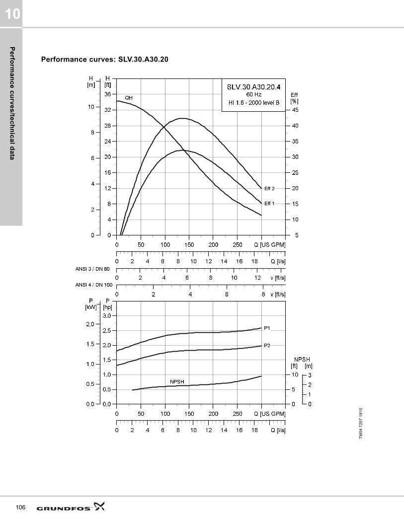
Pe
rform
an
ce
cu
rve
s/te
ch
nic
al d
ata
10
106
Performance curves: SLV.30.A30.20
TM
04
72
57
18
10
0 50 100 150 200 250 Q [US GPM]
0
4
8
12
16
20
24
28
32
36
[ft]H
0 2 4 6 8 10 12 v [ft/s]
5
10
15
20
25
30
35
40
45
[%]Eff
0 2 4 6 8 v [ft/s]
0 2 4 6 8 10 12 14 16 18 Q [l/s]
0
2
4
6
8
10
[m]H
SLV.30.A30.20.4
60 Hz
HI 1.6 - 2000 level B
Eff 2
Eff 1
QH
ANSI 3 / DN 80
ANSI 4 / DN 100
0 50 100 150 200 250 Q [US GPM]
0.0
0.5
1.0
1.5
2.0
2.5
3.0
[hp]P
0 2 4 6 8 10 12 14 16 18 Q [l/s]
0
5
10
[ft]NPSH
0.0
0.5
1.0
1.5
2.0
[kW]P
0
1
2
3
[m]
NPSH
P2
P1
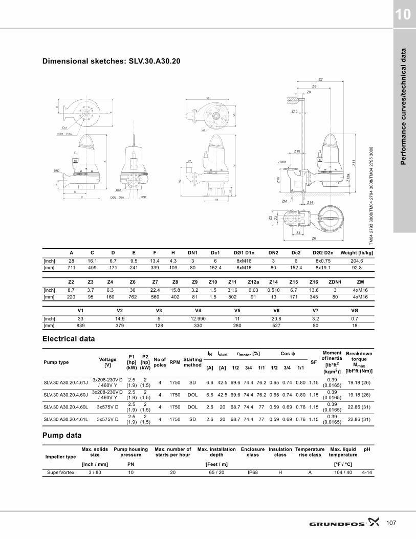
Pe
rfo
rma
nc
e c
urv
es
/te
ch
nic
al
da
ta
10
Dimensional sketches: SLV.30.A30.20
Electrical data
Pump data
TM
04
27
93
30
08
/TM
04
27
94
30
08
/TM
04
27
95
30
08
A C D E F H DN1 Dc1 DØ1 D1n DN2 Dc2 DØ2 D2n Weight [lb/kg]
[inch] 28 16.1 6.7 9.5 13.4 4.3 3 6 8xM16 3 6 8x0.75 204.6
[mm] 711 409 171 241 339 109 80 152.4 8xM16 80 152.4 8x19.1 92.8
Z2 Z3 Z4 Z6 Z7 Z8 Z9 Z10 Z11 Z12a Z14 Z15 Z16 ZDN1 ZM
[inch] 8.7 3.7 6.3 30 22.4 15.8 3.2 1.5 31.6 0.03 0.510 6.7 13.6 3 4xM16
[mm] 220 95 160 762 569 402 81 1.5 802 91 13 171 345 80 4xM16
V1 V2 V3 V4 V5 V6 V7 VØ
[inch] 33 14.9 5 12.990 11 20.8 3.2 0.7
[mm] 839 379 128 330 280 527 80 18
Pump typeVoltage
[V]
P1 [hp] (kW)
P2 [hp] (kW)
No of poles
RPMStarting method
IN Istart ηmotor [%] Cos ϕ
SF
Moment of inertia
[lb*ft2
(kgm2)]
Breakdown torque Mmax
[lbf*ft (Nm)][A] [A] 1/2 3/4 1/1 1/2 3/4 1/1
SLV.30.A30.20.4.61J3x208-230V D
/ 460V Y2.5
(1.9)2
(1.5)4 1750 SD 6.6 42.5 69.6 74.4 76.2 0.65 0.74 0.80 1.15
0.39 (0.0165)
19.18 (26)
SLV.30.A30.20.4.60J3x208-230V D
/ 460V Y2.5
(1.9)2
(1.5)4 1750 DOL 6.6 42.5 69.6 74.4 76.2 0.65 0.74 0.80 1.15
0.39 (0.0165)
19.18 (26)
SLV.30.A30.20.4.60L 3x575V D2.5
(1.9)2
(1.5)4 1750 DOL 2.6 20 68.7 74.4 77 0.59 0.69 0.76 1.15
0.39 (0.0165)
22.86 (31)
SLV.30.A30.20.4.61L 3x575V D2.5
(1.9)2
(1.5)4 1750 SD 2.6 20 68.7 74.4 77 0.59 0.69 0.76 1.15
0.39 (0.0165)
22.86 (31)
Impeller type
Max. solids size
Pump housing pressure
Max. number of starts per hour
Max. installation depth
Enclosure class
Insulation class
Temperature rise class
Max. liquid temperature
pH
[Inch / mm] PN [Feet / m] [°F / °C]
SuperVortex 3 / 80 10 20 65 / 20 IP68 H A 104 / 40 4-14
107
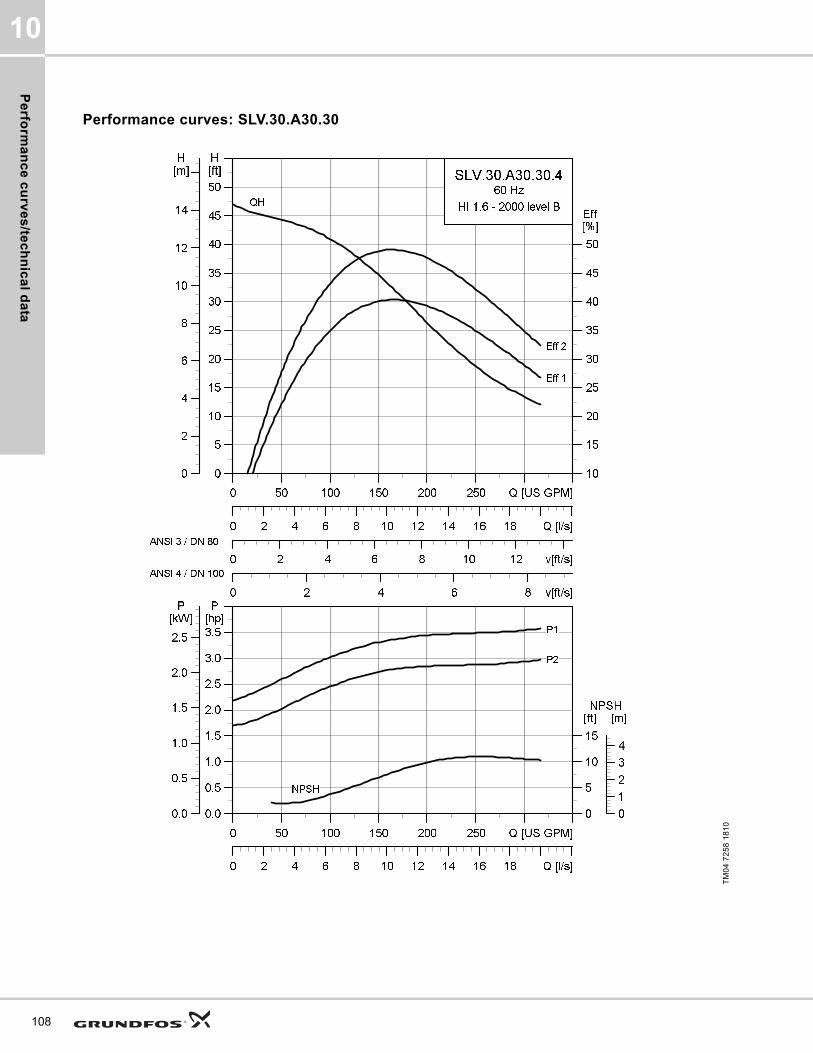
Pe
rform
an
ce
cu
rve
s/te
ch
nic
al d
ata
10
108
Performance curves: SLV.30.A30.30
TM
04
72
58
18
10
0 50 100 150 200 250 Q [US GPM]
0
5
10
15
20
25
30
35
40
45
50
[ft]H
0 2 4 6 8 10 12 v[ft/s]
10
15
20
25
30
35
40
45
50
[%]Eff
0 2 4 6 8 v[ft/s]
0 2 4 6 8 10 12 14 16 18 Q [l/s]
0
2
4
6
8
10
12
14
[m]H
SLV.30.A30.30.4
60 Hz
HI 1.6 - 2000 level B
Eff 2
Eff 1
QH
ANSI 3 / DN 80
ANSI 4 / DN 100
0 50 100 150 200 250 Q [US GPM]
0.0
0.5
1.0
1.5
2.0
2.5
3.0
3.5
[hp]P
0 2 4 6 8 10 12 14 16 18 Q [l/s]
0
5
10
15
[ft]NPSH
0.0
0.5
1.0
1.5
2.0
2.5
[kW]P
0
1
2
3
4
[m]
NPSH
P2
P1

Pe
rfo
rma
nc
e c
urv
es
/te
ch
nic
al
da
ta
10
Dimensional sketches: SLV.30.A30.30
Electrical data
Pump data
TM
04
27
93
30
08
/TM
04
27
94
30
08
/TM
04
27
95
30
08
A C D E F H DN1 Dc1 DØ1 D1n DN2 Dc2 DØ2 D2n Weight [lb/kg]
[inch] 28 16.1 6.7 9.5 13.4 4.3 3 6 8xM16 3 6 8x0.75 231.7
[mm] 711 409 171 241 339 109 80 152.4 8xM16 80 152.4 8x19.1 105.1
Z2 Z3 Z4 Z6 Z7 Z8 Z9 Z10 Z11 Z12a Z14 Z15 Z16 ZDN1 ZM
[inch] 8.7 3.7 6.3 30 22.4 15.8 3.2 1.5 31.6 0.03 0.51 6.7 13.6 3 4xM16
[mm] 220 95 160 762 569 402 81 1.5 802 91 13 171 345 80 4xM16
V1 V2 V3 V4 V5 V6 V7 VØ
[inch] 33 14.9 5 12.99 11 20.8 3.2 0.7
[mm] 839 379 128 330 280 527 80 18
Pump typeVoltage
[V]
P1 [hp] (kW)
P2 [hp] (kW)
No of poles
RPMStarting method
IN Istart ηmotor [%] Cos ϕ
SF
Moment of inertia
[lb*ft2
(kgm2)]
Breakdown torque Mmax
[lbf*ft (Nm)][A] [A] 1/2 3/4 1/1 1/2 3/4 1/1
SLV.30.A30.30.4.61L 3x575V D3.6
(2.7)3
(2.2)4 1760 SD 3.5 29 77.5 81.3 82.9 0.62 0.72 0.79 1.15
0.54 (0.0229)
32.45 (44)
SLV.30.A30.30.4.61J3x208-230V D
/ 460V Y3.6
(2.7)3
(2.2)4 1750 SD 8.7 61.6 78.2 81.5 82.1 0.69 0.78 0.83 1.15
0.54 (0.0229)
26.55 (36)
SLV.30.A30.30.4.61H 3x460V D3.6
(2.7)3
(2.2)4 1770 SD 4.5 39.7 76.9 80.7 83 0.57 0.69 0.76 1.15
0.54 (0.0229)
35.4 (48)
Impeller type
Max. solids size
Pump housing pressure
Max. number of starts per hour
Max. installation depth
Enclosure class
Insulation class
Temperature rise class
Max. liquid temperature
pH
[Inch / mm] PN [Feet / m] [°F / °C]
SuperVortex 3 / 80 10 20 65 / 20 IP68 H A 104 / 40 4-14
109

Pe
rform
an
ce
cu
rve
s/te
ch
nic
al d
ata
10
110
Performance curves: SLV.30.A30.55. 2-pole
TM
04
72
59
18
10
0 50 100 150 200 250 Q [US GPM]
0
10
20
30
40
50
60
70
[ft]H
0 2 4 6 8 10 12 v [ft/s]
0
5
10
15
20
25
30
[%]Eff
0 2 4 6 8 v [ft/s]
0 2 4 6 8 10 12 14 16 18 Q [l/s]
0
5
10
15
20
[m]H
SLV.30.A30.55.2
60 Hz
HI 1.6 - 2000 level B
Eff 2
Eff 1
QH
ANSI 3 / DN 80
ANSI 4 / DN 100
0 50 100 150 200 250 Q [US GPM]
1
2
3
4
5
6
7
[hp]P
0 2 4 6 8 10 12 14 16 18 Q [l/s]
0
10
20
30
[ft]NPSH
1
2
3
4
5
[kW]P
0
2
4
6
8
[m]
NPSH
P2
P1

Pe
rfo
rma
nc
e c
urv
es
/te
ch
nic
al
da
ta
10
Dimensional sketches: SLV.30.A30.55. 2-pole
Electrical data
Pump data
TM
04
27
93
30
08
/TM
04
27
94
30
08
/TM
04
27
95
30
08
A C D E F H DN1 Dc1 DØ1 D1n DN2 Dc2 DØ2 D2n Weight [lb/kg]
[inch] 29.5 18.1 7.9 10.5 15.5 4.3 3 6 8xM16 3 6 8x0.75 267.6
[mm] 748 460 200 267 393 104 80 152.4 8xM16 80 152.4 8x19.1 121.4
Z2 Z3 Z4 Z6 Z7 Z8 Z9 Z10 Z11 Z12a Z14 Z15 Z16 ZDN1 ZM
[inch] 8.7 3.7 6.3 32 24.4 16.9 3.2 1.5 32.6 0.03 0.51 6.7 13.6 3 4xM16
[mm] 220 95 160 813 620 428 81 1.5 829 96 13 171 345 80 4xM16
V1 V2 V3 V4 V5 V6 V7 VØ
[inch] 34.5 14.9 5 12.99 11 20.8 3.2 0.7
[mm] 876 379 128 330 280 578 80 18
Pump typeVoltage
[V]
P1 [hp] (kW)
P2 [hp] (kW)
No of poles
RPMStarting method
IN Istart ηmotor [%] Cos ϕ
SF
Moment of inertia
[lb*ft2
(kgm2)]
Breakdown torque Mmax
[lbf*ft (Nm)][A] [A] 1/2 3/4 1/1 1/2 3/4 1/1
SLV.30.A30.55.2.61J3x208-230V D
/ 460V Y6.6
(4.9)5.5 (4)
2 3530 SD 14.8 152 75 79.9 81.7 0.78 0.86 0.90 1.150.35
(0.0149)53.51 (72.5)
SLV.30.A30.55.2.61L 3x575V D6.6
(4.9)5.5 (4)
2 3535 SD 5.8 70.8 74.1 79.6 82 0.71 0.82 0.87 1.150.35
(0.0149)44.99 (61)
SLV.30.A30.55.2.61H 3x460V D6.6
(4.9)5.5 (4)
2 3540 SD 7.4 96.8 73.6 79.2 82 0.68 0.80 0.85 1.150.35
(0.0149)37.62 (51)
Impeller type
Max. solids size
Pump housing pressure
Max. number of starts per hour
Max. installation depth
Enclosure class
Insulation class
Temperature rise class
Max. liquid temperature
pH
[Inch / mm] PN [Feet / m] [°F / °C]
SuperVortex 3 / 80 10 20 65 / 20 IP68 H A 104 / 40 4-14
111
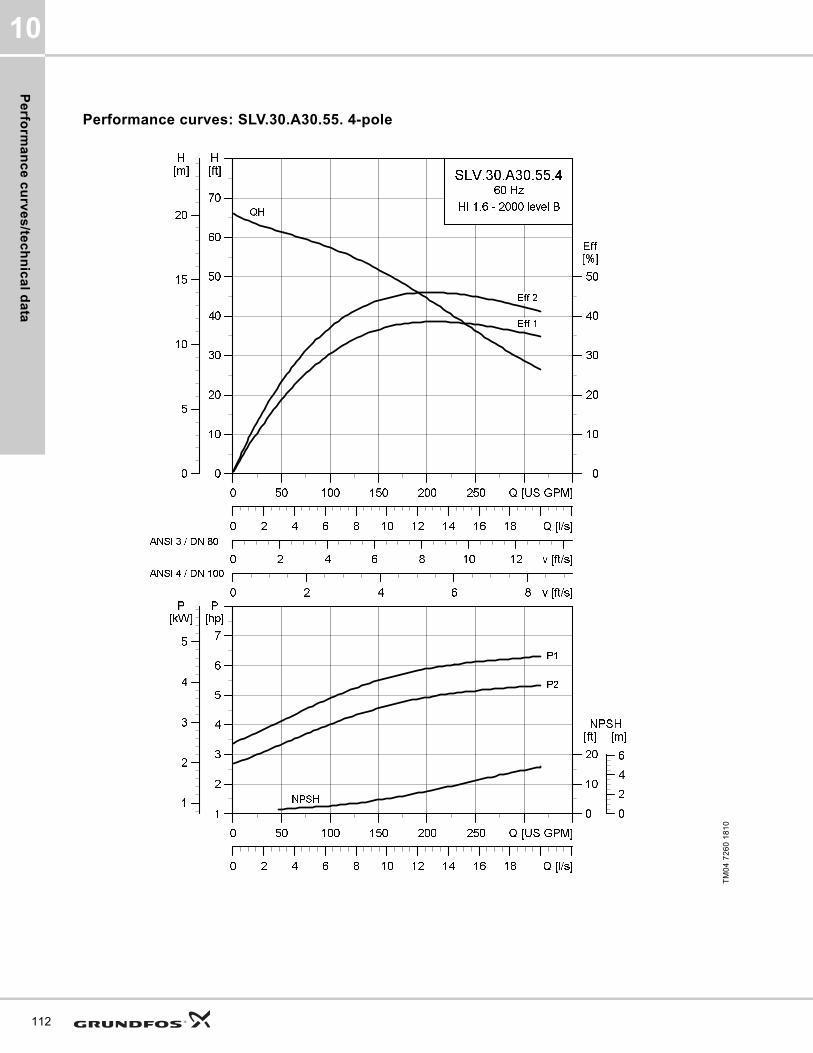
Pe
rform
an
ce
cu
rve
s/te
ch
nic
al d
ata
10
112
Performance curves: SLV.30.A30.55. 4-pole
TM
04
72
60
18
10
0 50 100 150 200 250 Q [US GPM]
0
10
20
30
40
50
60
70
[ft]H
0 2 4 6 8 10 12 v [ft/s]
0
10
20
30
40
50
[%]Eff
0 2 4 6 8 v [ft/s]
0 2 4 6 8 10 12 14 16 18 Q [l/s]
0
5
10
15
20
[m]H
SLV.30.A30.55.4
60 Hz
HI 1.6 - 2000 level B
Eff 2
Eff 1
QH
ANSI 3 / DN 80
ANSI 4 / DN 100
0 50 100 150 200 250 Q [US GPM]
1
2
3
4
5
6
7
[hp]P
0 2 4 6 8 10 12 14 16 18 Q [l/s]
0
10
20
[ft]NPSH
1
2
3
4
5
[kW]P
0
2
4
6
[m]
NPSH
P2
P1

Pe
rfo
rma
nc
e c
urv
es
/te
ch
nic
al
da
ta
10
Dimensional sketches: SLV.30.A30.55. 4-pole
Electrical data
Pump data
TM
04
27
93
30
08
/TM
04
27
94
30
08
/TM
04
27
95
30
08
A C D E F H DN1 Dc1 DØ1 D1n DN2 Dc2 DØ2 D2n Weight [lb/kg]
[inch] 29.3 18 7.9 10.9 15 4.1 3 6 8xM16 3 6 8x0.75 294.3
[mm] 744 456 200 276 380 109 80 152.4 8xM16 80 152.4 8x19.1 133.5
Z2 Z3 Z4 Z6 Z7 Z8 Z9 Z10 Z11 Z12a Z14 Z15 Z16 ZDN1 ZM
[inch] 8.7 3.7 6.3 31.9 24.3 17.2 3.2 1.5 33.1 0.03 0.510 6.7 13.6 3 4xM16
[mm] 220 95 160 809 617 437 81 1.5 840 91 13 171 345 80 4xM16
V1 V2 V3 V4 V5 V6 V7 VØ
[inch] 34.3 14.7 5 12.99 11 22.6 3.2 0.7
[mm] 872 374 128 330 280 574 80 18
Pump typeVoltage
[V]
P1 [hp] (kW)
P2 [hp] (kW)
No of poles
RPMStarting method
IN Istart ηmotor [%] Cos ϕ
SF
Moment of inertia
[lb*ft2
(kgm2)]
Breakdown torque Mmax
[lbf*ft (Nm)][A] [A] 1/2 3/4 1/1 1/2 3/4 1/1
SLV.30.A30.55.4.61J3x208-230V D
/ 460V Y6.4
(4.8)5.5 (4)
4 1760 SD 16.1 79.4 79.9 83.3 83.9 0.61 0.74 0.80 1.151.28
(0.054)81.58
(110.6)
SLV.30.A30.55.4.61L 3x575V D6.4
(4.8)5.5 (4)
4 1765 SD 6.5 37.5 79.2 83.3 84.7 0.54 0.67 0.75 1.151.28
(0.054)68.59 (93)
SLV.30.A30.55.4.61H 3x460V D6.4
(4.8)5.5 (4)
4 1770 SD 8.5 51.5 78.3 82.6 84.4 0.5 0.64 0.72 1.151.28
(0.054)74.49 (101)
Impeller type
Max. solids size
Pump housing pressure
Max. number of starts per hour
Max. installation depth
Enclosure class
Insulation class
Temperature rise class
Max. liquid temperature
pH
[Inch / mm] PN [Feet / m] [°F / °C]
SuperVortex 3 / 80 10 20 65 / 20 IP68 H A 104 / 40 4-14
113
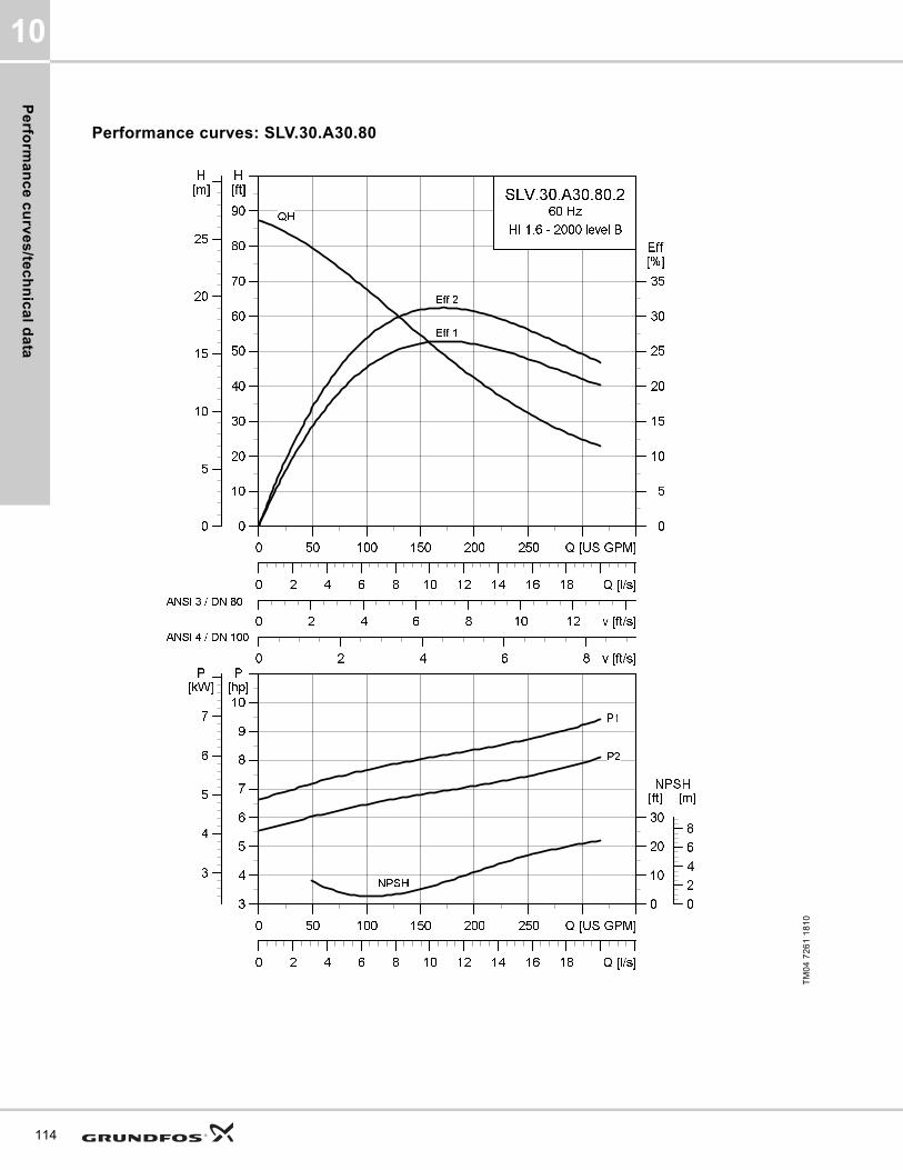
Pe
rform
an
ce
cu
rve
s/te
ch
nic
al d
ata
10
114
Performance curves: SLV.30.A30.80
TM
04
72
61
18
10
0 50 100 150 200 250 Q [US GPM]
0
10
20
30
40
50
60
70
80
90
[ft]H
0 2 4 6 8 10 12 v [ft/s]
0
5
10
15
20
25
30
35
[%]Eff
0 2 4 6 8 v [ft/s]
0 2 4 6 8 10 12 14 16 18 Q [l/s]
0
5
10
15
20
25
[m]H
SLV.30.A30.80.2
60 Hz
HI 1.6 - 2000 level B
Eff 2
Eff 1
QH
ANSI 3 / DN 80
ANSI 4 / DN 100
0 50 100 150 200 250 Q [US GPM]
3
4
5
6
7
8
9
10
[hp]P
0 2 4 6 8 10 12 14 16 18 Q [l/s]
0
10
20
30
[ft]NPSH
3
4
5
6
7
[kW]P
0
2
4
6
8
[m]
NPSH
P2
P1

Pe
rfo
rma
nc
e c
urv
es
/te
ch
nic
al
da
ta
10
Dimensional sketches: SLV.30.A30.80
Electrical data
Pump data
TM
04
27
93
30
08
/TM
04
27
94
30
08
/TM
04
27
95
30
08
A C D E F H DN1 Dc1 DØ1 D1n DN2 Dc2 DØ2 D2n Weight [lb/kg]
[inch] 29.6 18 7.900 10.9 15 4.1 3 6 8xM16 3 6 8x0.75 305.6
[mm] 751 456 200 276 380 104 80 152.4 8xM16 80 152.4 8x 19.1 138.6
Z2 Z3 Z4 Z6 Z7 Z8 Z9 Z10 Z11 Z12a Z14 Z15 Z16 ZDN1 ZM
[inch] 8.7 3.7 6.3 31.9 24.3 17.2 3.2 1.5 33.4 0.03 0.51 6.7 13.6 3 4xM16
[mm] 220 95 160 809 617 437 81 1.5 847 96 13 171 345 80 4xM16
V1 V2 V3 V4 V5 V6 V7 VØ
[inch] 34.6 14.7 5 12.990 11 22.6 3.2 0.7
[mm] 879 374 128 330 280 574 80 18
Pump typeVoltage
[V]
P1 [hp] (kW)
P2 [hp] (kW)
No of poles
RPMStarting method
IN Istart ηmotor [%] Cos ϕ
SF
Moment of inertia
[lb*ft2
(kgm2)]
Breakdown torque Mmax
[lbf*ft (Nm)][A] [A] 1/2 3/4 1/1 1/2 3/4 1/1
SLV.30.A30.80.2.61J3x208-230V D
/ 460 V Y11.7 (8.7)
10 (7.5)
2 3520 SD 26.5 191 83 85.2 85.4 0.82 0.88 0.90 1.150.45
(0.019)71.1 (96.4)
SLV.30.A30.80.2.61L 3x575V D11.7 (8.7)
10 (7.5)
2 3525 SD 10.2 89 82.9 86 86.8 0.76 0.84 0.88 1.150.45
(0.019)59.74 (81)
SLV.30.A30.80.2.61H 3x460V D11.7 (8.7)
10 (7.5)
2 3550 SD 13.2 116 80.9 84.3 86.5 0.73 0.81 0.86 1.150.45
(0.019)65.64 (89)
Impeller type
Max. solids size
Pump housing pressure
Max. number of starts per hour
Max. installation depth
Enclosure class
Insulation class
Temperature rise class
Max. liquid temperature
pH
[Inch / mm] PN [Feet / m] [°F / °C]
SuperVortex 3 / 80 10 20 65 / 20 IP68 H B 104 / 40 4-14
115
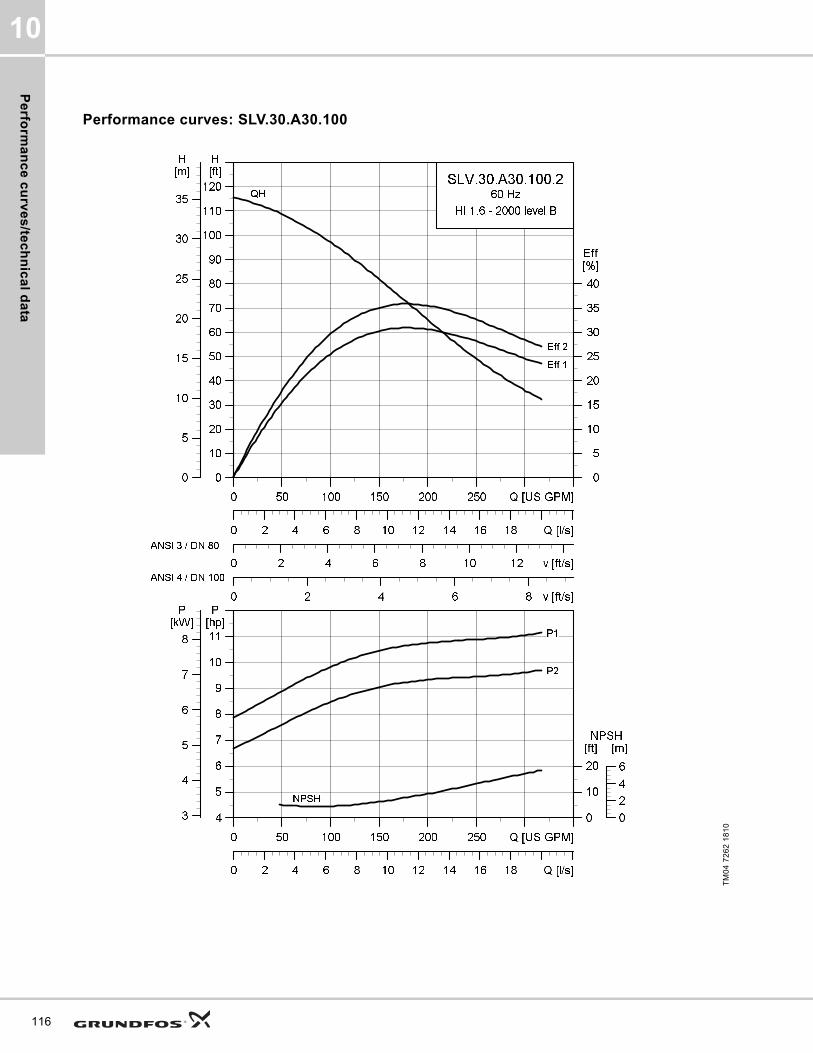
Pe
rform
an
ce
cu
rve
s/te
ch
nic
al d
ata
10
116
Performance curves: SLV.30.A30.100
TM
04
72
62
18
10
0 50 100 150 200 250 Q [US GPM]
0
10
20
30
40
50
60
70
80
90
100
110
120
[ft]H
0 2 4 6 8 10 12 v [ft/s]
0
5
10
15
20
25
30
35
40
[%]Eff
0 2 4 6 8 v [ft/s]
0 2 4 6 8 10 12 14 16 18 Q [l/s]
0
5
10
15
20
25
30
35
[m]H
SLV.30.A30.100.2
60 Hz
HI 1.6 - 2000 level B
Eff 2
Eff 1
QH
ANSI 3 / DN 80
ANSI 4 / DN 100
0 50 100 150 200 250 Q [US GPM]
4
5
6
7
8
9
10
11
[hp]P
0 2 4 6 8 10 12 14 16 18 Q [l/s]
0
10
20
[ft]NPSH
3
4
5
6
7
8
[kW]P
0
2
4
6
[m]
NPSH
P2
P1

Pe
rfo
rma
nc
e c
urv
es
/te
ch
nic
al
da
ta
10
Dimensional sketches: SLV.30.A30.100
Electrical data
Pump data
TM
04
27
93
30
08
/TM
04
27
94
30
08
/TM
04
27
95
30
08
A C D E F H DN1 Dc1 DØ1 D1n DN2 Dc2 DØ2 D2n Weight [lb/kg]
[inch] 29.57 17.95 7.870 10.87 14.960 4.09 3 6 8xM16 3 6 8x0.75 306.7
[mm] 751 456 200 276 380 104 80 152.4 8xM16 80 152.4 8x19.1 139.1
Z2 Z3 Z4 Z6 Z7 Z8 Z9 Z10 Z11 Z12a Z14 Z15 Z16 ZDN1 ZM
[inch] 8.7 3.7 6.3 31.9 24.3 17.2 3.2 1.5 33.4 0.03 0.510 6.7 13.6 3 4xM16
[mm] 220 95 160 809 617 437 81 1.5 847 96 13 171 345 80 4xM16
V1 V2 V3 V4 V5 V6 V7 VØ
[inch] 34.610 14.720 5.040 12.990 11.020 22.6 3.2 0.7
[mm] 879 374 128 330 280 574 80 18
Pump typeVoltage
[V]
P1 [hp] (kW)
P2 [hp] (kW)
No
of
po
les
RPMStarting method
IN Istart ηmotor [%] Cos ϕ
SF
Moment of inertia
[lb*ft2
(kgm2)]
Breakdown torque Mmax
[lbf*ft (Nm)][A] [A] 1/2 3/4 1/1 1/2 3/4 1/1
SLV.30.A30.100.2.61J3x208-230V D
/ 460V Y11.7 (8.7)
10 (7.5)
2 3520 SD 26.5 191 83 85.2 85.4 0.82 0.88 0.9 1.150.52
(0.022)71.1 (96.4)
SLV.30.A30.100.2.61L 3x575V D11.7 (8.7)
10 (7.5)
2 3525 SD 10.2 89 82.9 86 86.8 0.76 0.84 0.88 1.150.52
(0.022)59.74 (81)
SLV.30.A30.100.2.61H 3x460V D11.7 (8.7)
10 (7.5)
2 3550 SD 13.2 116 80.9 84.4 85.5 0.73 0.81 0.86 1.150.52
(0.022)65.64 (89)
Impeller type
Max. solids size
Pump housing pressure
Max. number of starts per hour
Max. installation depth
Enclosure class
Insulation class
Temperature rise class
Max. liquid temperature
pH
[Inch / mm] PN [Feet / m] [°F / °C]
SuperVortex 3 / 80 10 20 65 / 20 IP68 H B 104 / 40 4-14
117
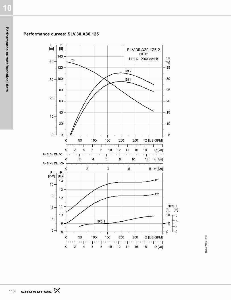
Pe
rform
an
ce
cu
rve
s/te
ch
nic
al d
ata
10
118
Performance curves: SLV.30.A30.125
TM
04
72
63
18
10
0 50 100 150 200 250 Q [US GPM]
0
20
40
60
80
100
120
140
[ft]H
0 2 4 6 8 10 12 v [ft/s]
5
10
15
20
25
30
35
[%]Eff
0 2 4 6 8 v [ft/s]
0 2 4 6 8 10 12 14 16 18 Q [l/s]
0
10
20
30
40
[m]H
SLV.30.A30.125.2
60 Hz
HI 1.6 - 2000 level B
Eff 2
Eff 1
QH
ANSI 3 / DN 80
ANSI 4 / DN 100
0 50 100 150 200 250 Q [US GPM]
8
9
10
11
12
13
14
[hp]P
0 2 4 6 8 10 12 14 16 18 Q [l/s]
0
10
20
[ft]NPSH
6
7
8
9
10
[kW]P
0
2
4
6
[m]
NPSH
P2
P1

Pe
rfo
rma
nc
e c
urv
es
/te
ch
nic
al
da
ta
10
Dimensional sketches: SLV.30.A30.125
Electrical data
Pump data
* SLV.30.A30.125.2.61H are temperature rise class B
TM
04
27
93
30
08
/TM
04
27
94
30
08
/TM
04
27
95
30
08
A C D E F H DN1 Dc1 DØ1 D1n DN2 Dc2 DØ2 D2n Weight [lb/kg]
[inch] 30.8 19.3 8.5 11.5 16.3 4.8 3 6 8xM16 3 6 8x0.75 399.9
[mm] 782 489 217 293 413 123 80 152.4 8xM16 80 152.4 8x19.1 181.4
Z2 Z3 Z4 Z6 Z7 Z8 Z9 Z10 Z11 Z12a Z14 Z15 Z16 ZDN1 ZM
[inch] 8.7 3.7 6.3 33.2 25.6 17.9 3.2 1.5 33.8 0.03 0.51 6.7 13.6 3 4xM16
[mm] 220 95 160 842 650 454 81 1.5 858 77 13 171 345 80 4xM16
V1 V2 V3 V4 V5 V6 V7 VØ
[inch] 35.8 15.5 5 13 11 23.9 3.2 0.7
[mm] 910 393 128 330 280 607 80 18
Pump typeVoltage
[V]
P1 [hp] (kW)
P2 [hp] (kW)
No
of
po
les
RPMStarting method
IN Istart ηmotor [%] Cos ϕ
SF
Moment of inertia
[lb*ft2
(kgm2)]
Breakdown torque Mmax [lbf*ft (Nm)]
[A] [A] 1/2 3/4 1/1 1/2 3/4 1/1
SLV.30.A30.125.2.61J3x208-230V D
/ 460V Y17
(12.7)15
(11)2 3545 SD 38.2 251 85.6 87.3 87 0.84 0.89 0.90 1.15
1.21 (0.051)
79.66 (108)
SLV.30.A30.125.2.61L 3x575V D17
(12.7)15
(11)2 3550 SD 14.5 115 85.8 88.1 88.5 0.80 0.86 0.89 1.15
1.21 (0.051)
67.12 (91)
SLV.30.A30.125.2.61H 3x460V D17
(12.7)15
(11)2 3550 SD 18.2 157 85.9 88.1 88.7 0.77 0.85 0.88 1.15
1.21 (0.051)
73.02 (99)
Impeller type
Max. solids size
Pump housing pressure
Max. number of starts per hour
Max. installation depth
Enclosure class
Insulation class
Temperature rise class
Max. liquid temperature
pH
[Inch / mm] PN [Feet / m] [°F / °C]
SuperVortex 3 / 80 10 20 65 / 20 IP68 H A (B)* 104 / 40 4-14
119
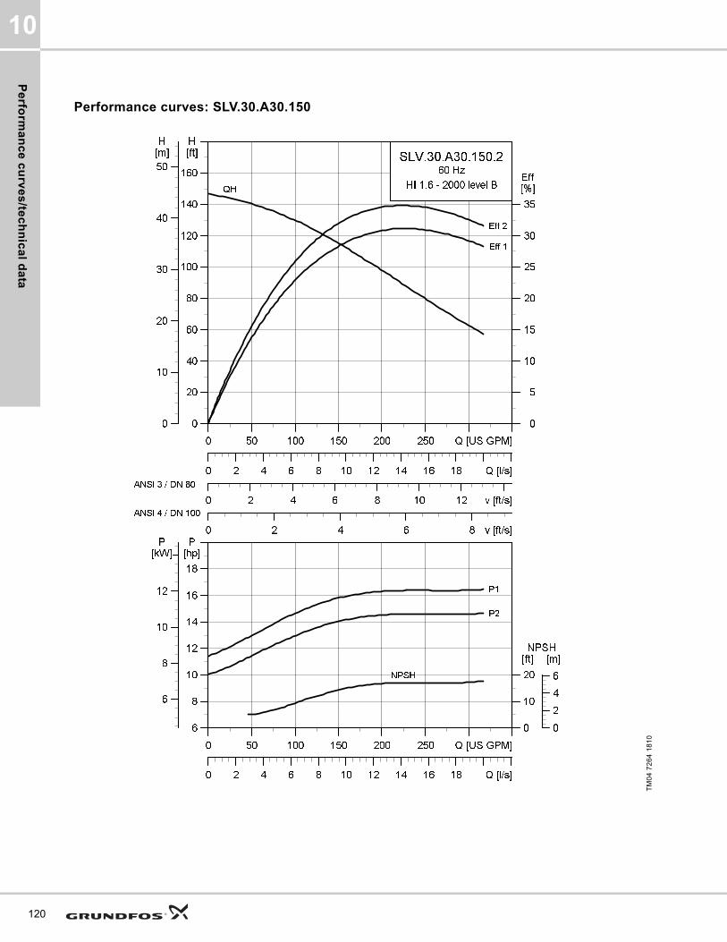
Pe
rform
an
ce
cu
rve
s/te
ch
nic
al d
ata
10
120
Performance curves: SLV.30.A30.150
TM
04
72
64
18
10
0 50 100 150 200 250 Q [US GPM]
0
20
40
60
80
100
120
140
160
[ft]H
0 2 4 6 8 10 12 v [ft/s]
0
5
10
15
20
25
30
35
[%]Eff
0 2 4 6 8 v [ft/s]
0 2 4 6 8 10 12 14 16 18 Q [l/s]
0
10
20
30
40
50
[m]H
SLV.30.A30.150.2
60 Hz
HI 1.6 - 2000 level B
Eff 2
Eff 1
QH
ANSI 3 / DN 80
ANSI 4 / DN 100
0 50 100 150 200 250 Q [US GPM]
6
8
10
12
14
16
18
[hp]P
0 2 4 6 8 10 12 14 16 18 Q [l/s]
0
10
20
[ft]NPSH
6
8
10
12
[kW]P
0
2
4
6
[m]
NPSH
P2
P1

Pe
rfo
rma
nc
e c
urv
es
/te
ch
nic
al
da
ta
10
Dimensional sketches: SLV.30.A30.150
Electrical data
Pump data
* SLV.30.A30.150.2.61H are temperature rise class B
TM
04
27
93
30
08
/TM
04
27
94
30
08
/TM
04
27
95
30
08
A C D E F H DN1 Dc1 DØ1 D1n DN2 Dc2 DØ2 D2n Weight [lb/kg]
[inch] 30.8 19.3 8.5 11.5 16.3 4.8 3 6 8xM16 3 6 8x0.75 400.4
[mm] 782 489 217 293 413 123 80 152.4 8xM16 80 152.4 8x19.1 181.6
Z2 Z3 Z4 Z6 Z7 Z8 Z9 Z10 Z11 Z12a Z14 Z15 Z16 ZDN1 ZM
[inch] 8.7 3.7 6.3 33.2 25.6 17.9 3.2 1.5 33.8 0.03 0.51 6.7 13.6 3 4xM16
[mm] 220 95 160 842 650 454 81 1.5 858 77 13 171 345 80 4xM16
V1 V2 V3 V4 V5 V6 V7 VØ
[inch] 35.8 15.5 5 13 11 23.9 3.2 0.7
[mm] 910 393 128 330 280 607 80 18
Pump typeVoltage
[V]
P1 [hp] (kW)
P2 [hp] (kW)
No
of
po
les
RPMStarting method
IN Istart ηmotor [%] Cos ϕ
SF
Moment of
inertia
[lb*ft2
(kgm2)]
Breakdown torque Mmax
[lbf*ft (Nm)][A] [A] 1/2 3/4 1/1 1/2 3/4 1/1
SLV.30.A30.150.2.61J3x208-230V D
/ 460V Y17
(12.7)15
(11)2 3545 SD 38.2 251 85.6 87.3 87 0.84 0.89 0.90 1.15
1.26 (0.053)
79.66 (108)
SLV.30.A30.150.2.61L 3x575V D17
(12.7)15
(11)2 3550 SD 14.5 115 85.8 88.1 88.5 0.80 0.86 0.89 1.15
1.26 (0.053)
67.12 (91)
SLV.30.A30.150.2.61H 3x460V D17
(12.7)15
(11)2 3550 SD 18.2 157 85.9 88.1 88.7 0.77 0.85 0.88 1.15
1.26 (0.053)
73.02 (99)
Impeller type
Max. solids size
Pump housing pressure
Max. number of starts per hour
Max. installation depth
Enclosure class
Insulation class
Temperature rise class
Max. liquid temperature
pH
[Inch / mm] PN [Feet / m] [°F / °C]
SuperVortex 3 / 80 10 20 65 / 20 IP68 H A (B)* 104 / 40 4-14
121
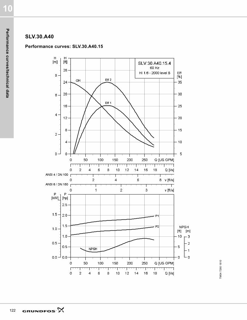
Pe
rform
an
ce
cu
rve
s/te
ch
nic
al d
ata
10
122
SLV.30.A40
Performance curves: SLV.30.A40.15
TM
04
72
60
18
10
0 50 100 150 200 250 Q [US GPM]
0
4
8
12
16
20
24
28
[ft]H
0 2 4 6 8 v [ft/s]
5
10
15
20
25
30
35
[%]Eff
0 1 2 3 v [ft/s]
0 2 4 6 8 10 12 14 16 18 Q [l/s]
0
2
4
6
8
[m]H
SLV.30.A40.15.4
60 Hz
HI 1.6 - 2000 level B
Eff 2
Eff 1
QH
ANSI 4 / DN 100
ANSI 6 / DN 150
0 50 100 150 200 250 Q [US GPM]
0.0
0.5
1.0
1.5
2.0
2.5
[hp]P
0 2 4 6 8 10 12 14 16 18 Q [l/s]
0
5
10
[ft]NPSH
0.0
0.5
1.0
1.5
[kW]P
0
1
2
3
[m]
NPSH
P2
P1

Pe
rfo
rma
nc
e c
urv
es
/te
ch
nic
al
da
ta
10
Dimensional sketches: SLV.30.A40.15
Electrical data
Pump data
TM
04
27
93
30
08
/TM
04
27
94
30
08
/TM
04
27
95
30
08
A C D E F H DN1 Dc1 DØ1 D1n DN2 Dc2 DØ2 D2n Weight [lb/kg]
[inch] 28 16 6.7 9.5 13.3 4.3 3 6 8xM16 4 7.5 8x0.75 207.7
[mm] 711 407 171 241 336.5 109 80 152.4 8xM16 100 190.5 8x19.1 94.2
Z2 Z3 Z4 Z6 Z7 Z8 Z9 Z10 Z11 Z12a Z14 Z15 Z16 ZDN1 ZM
[inch] 10.2 4.3 8.7 33.5 24.6 18 4.3 2 33.2 0.03 0 8.7 16.3 4 4xM16
[mm] 260 110 220 850 624 458 110 2 842 131 0 220 413 100 4xM16
V1 V2 V3 V4 V5 V6 V7 VØ
[inch] 33 13.9 5 13 11 21.6 3.9 0.7
[mm] 839 354 128 330 280 548.7 100 18
Pump typeVoltage
[V]
P1 [hp] (kW)
P2 [hp] (kW)
No of poles
RPMStarting method
IN Istart ηmotor [%] Cos ϕ
SF
Moment of inertia
[lb*ft2
(kgm2)]
Breakdown torque Mmax
[lbf*ft (Nm)][A] [A] 1/2 3/4 1/1 1/2 3/4 1/1
SLV.30.A40.15.4.61J3x208-230V D
/ 460V Y2
(1.5)1.5
(1.1)4 1750 SD 5.1 31.9 66.2 71.5 73.9 0.65 0.74 0.80 1.15
0.33 (0.014)
14.01 (19)
SLV.30.A40.15.4.60J3x208-230V D
/ 460V Y2
(1.5)1.5
(1.1)4 1750 DOL 5.1 31.9 66.2 71.5 73.9 0.65 0.74 0.80 1.15
0.33 (0.014)
14.01 (19)
SLV.30.A40.15.4.60L 3x575V D2
(1.5)1.5
(1.1)4 1755 DOL 2 14.9 65 71.4 74.5 0.59 0.69 0.75 1.15
0.33 (0.014)
16.96 (23)
SLV.30.A40.15.4.61L 3x575V D2
(1.5)1.5
(1.1)4 1755 SD 2 14.9 65 71.4 74.5 0.59 0.69 0.75 1.15
0.33 (0.014)
16.96 (23)
Impeller type
Max. solids size
Pump housing pressure
Max. number of starts per hour
Max. installation depth
Enclosure class
Insulation class
Temperature rise class
Max. liquid temperature
pH
[Inch / mm] PN [Feet / m] [°F / °C]
SuperVortex 3 / 80 10 20 65 / 20 IP68 H A 104 / 40 4-14
123
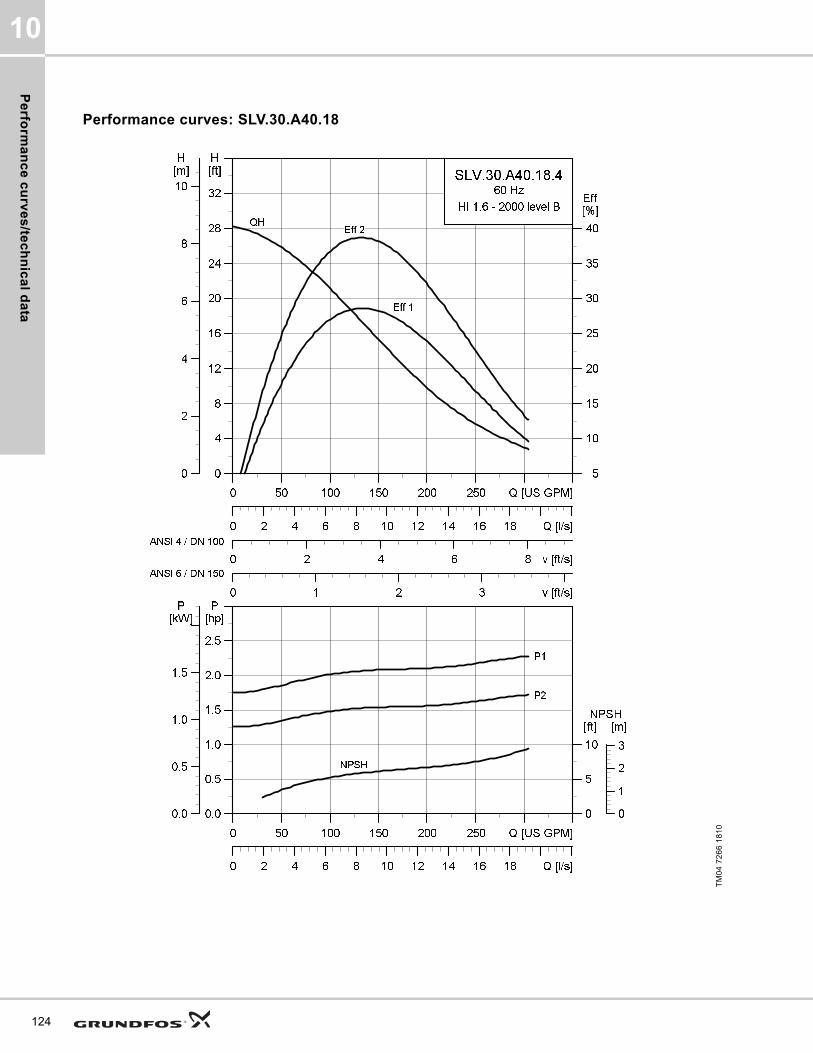
Pe
rform
an
ce
cu
rve
s/te
ch
nic
al d
ata
10
124
Performance curves: SLV.30.A40.18
TM
04
72
66
18
10
0 50 100 150 200 250 Q [US GPM]
0
4
8
12
16
20
24
28
32
[ft]H
0 2 4 6 8 v [ft/s]
5
10
15
20
25
30
35
40
[%]Eff
0 1 2 3 v [ft/s]
0 2 4 6 8 10 12 14 16 18 Q [l/s]
0
2
4
6
8
10
[m]H
SLV.30.A40.18.4
60 Hz
HI 1.6 - 2000 level B
Eff 2
Eff 1
QH
ANSI 4 / DN 100
ANSI 6 / DN 150
0 50 100 150 200 250 Q [US GPM]
0.0
0.5
1.0
1.5
2.0
2.5
[hp]P
0 2 4 6 8 10 12 14 16 18 Q [l/s]
0
5
10
[ft]NPSH
0.0
0.5
1.0
1.5
[kW]P
0
1
2
3
[m]
NPSH
P2
P1

Pe
rfo
rma
nc
e c
urv
es
/te
ch
nic
al
da
ta
10
Dimensional sketches: SLV.30.A40.18
Electrical data
Pump data
TM
04
27
93
30
08
/TM
04
27
94
30
08
/TM
04
27
95
30
08
A C D E F H DN1 Dc1 DØ1 D1n DN2 Dc2 DØ2 D2n Weight [lb/kg]
[inch] 28 16 6.7 9.5 13.3 4.3 3 6 8xM16 4 7.5 8x0.75 206.4
[mm] 711 407 171 241 336.5 109 80 152.4 8xM16 100 190.5 8x19.1 93.6
Z2 Z3 Z4 Z6 Z7 Z8 Z9 Z10 Z11 Z12a Z14 Z15 Z16 ZDN1 ZM
[inch] 10.2 4.3 8.7 33.5 24.6 18 4.3 2 33.2 0.03 0 8.7 16.3 4 4xM16
[mm] 260 110 220 850 624 458 110 2 842 131 0 220 413 100 4xM16
V1 V2 V3 V4 V5 V6 V7 VØ
[inch] 32 14.5 5.1 14 11.8 23.3 3.9 0.7
[mm] 812 369 130 355 300 591 100 18
Pump typeVoltage
[V]
P1 [hp] (kW)
P2 [hp] (kW)
No of poles
RPMStarting method
IN Istart ηmotor [%] Cos ϕ
SF
Moment of inertia
[lb*ft2
(kgm2)]
Breakdown torque Mmax
[lbf*ft (Nm)][A] [A] 1/2 3/4 1/1 1/2 3/4 1/1
SLV.30.A40.18.4.61J3x208-230V D
/ 460V Y2.5
(1.9)2
(1.5)4 1750 SD 6.6 42.5 69.6 74.4 76.2 0.65 0.74 0.80 1.15
0.37 (0.0155)
19.18 (26)
SLV.30.A40.18.4.60J3x208-230V D
/ 460V Y2.5
(1.9)2
(1.5)4 1750 DOL 6.6 42.5 69.6 74.4 76.2 0.65 0.74 0.80 1.15
0.37 (0.0155)
19.18 (26)
SLV.30.A40.18.4.60L 3x575V D2.5
(1.9)2
(1.5)4 1750 DOL 2.6 20 68.7 74.4 77 0.59 0.69 0.76 1.15
0.37 (0.0155)
22.86 (31)
SLV.30.A40.18.4.61L 3x575V D2.5
(1.9)2
(1.5)4 1750 SD 2.6 20 68.7 74.4 77 0.59 0.69 0.76 1.15
0.37 (0.0155)
22.86 (31)
Impeller type
Max. solids size
Pump housing pressure
Max. number of starts per hour
Max. installation depth
Enclosure class
Insulation class
Temperature rise class
Max. liquid temperature
pH
[Inch / mm] PN [Feet / m] [°F / °C]
SuperVortex 3 / 80 10 20 65 / 20 IP68 H A 104 / 40 4-14
125

Pe
rform
an
ce
cu
rve
s/te
ch
nic
al d
ata
10
126
Performance curves: SLV.30.A40.20
TM
04
72
67
18
10
0 50 100 150 200 250 300 Q [US GPM]
0
4
8
12
16
20
24
28
32
[ft]H
0 2 4 6 8 v [ft/s]
10
15
20
25
30
35
40
45
[%]Eff
0 1 2 3 4 v [ft/s]
0 2 4 6 8 10 12 14 16 18 20 22 Q [l/s]
0
2
4
6
8
10
[m]H
SLV.30.A40.20.4
60 Hz
HI 1.6 - 2000 level B
Eff 2
Eff 1
QH
ANSI 4 / DN 100
ANSI 6 / DN 150
0 50 100 150 200 250 300 Q [US GPM]
0.0
0.5
1.0
1.5
2.0
2.5
[hp]P
0 2 4 6 8 10 12 14 16 18 20 22 Q [l/s]
0
5
10
[ft]NPSH
0.0
0.5
1.0
1.5
[kW]P
0
1
2
3
[m]
NPSH
P2
P1

Pe
rfo
rma
nc
e c
urv
es
/te
ch
nic
al
da
ta
10
Dimensional sketches: SLV.30.A40.20
Electrical data
Pump data
TM
04
27
93
30
08
/TM
04
27
94
30
08
/TM
04
27
95
30
08
A C D E F H DN1 Dc1 DØ1 D1n DN2 Dc2 DØ2 D2n Weight [lb/kg]
[inch] 28 16 6.7 9.5 13.3 4.3 3 6 8xM16 4 7.5 8x0.75 206.8
[mm] 711 407 171 241 336.5 109 80 152.4 8xM16 100 190.5 8x19.1 93.8
Z2 Z3 Z4 Z6 Z7 Z8 Z9 Z10 Z11 Z12a Z14 Z15 Z16 ZDN1 ZM
[inch] 10.2 4.3 8.7 33.5 24.6 18 4.3 2 33.2 0.03 0 8.7 16.3 4 4xM16
[mm] 260 110 220 850 624 458 110 2 842 131 0 220 413 100 4xM16
V1 V2 V3 V4 V5 V6 V7 VØ
[inch] 32 14.5 5.1 14 11.8 23.3 3.9 0.7
[mm] 812 369 130 355 300 591 100 18
Pump typeVoltage
[V]
P1 [hp] (kW)
P2 [hp] (kW)
No of poles
RPMStarting method
IN Istart ηmotor [%] Cos ϕ
SF
Moment of inertia
[lb*ft2
(kgm2)]
Breakdown torque Mmax
[lbf*ft (Nm)][A] [A] 1/2 3/4 1/1 1/2 3/4 1/1
SLV.30.A40.20.4.61J3x208-230V D
/ 460V Y2.5
(1.9)2
(1.5)4 1750 SD 6.6 42.5 69.6 74.4 76.2 0.65 0.74 0.80 1.15
0.39 (0.0165)
19.18 (26)
SLV.30.A40.20.4.60J3x208-230V D
/ 460V Y2.5
(1.9)2
(1.5)4 1750 DOL 6.6 42.5 69.6 74.4 76.2 0.65 0.74 0.80 1.15
0.39 (0.0165)
19.18 (26)
SLV.30.A40.20.4.60L 3x575V D2.5
(1.9)2
(1.5)4 1750 DOL 2.6 20 68.7 74.4 77 0.59 0.69 0.76 1.15
0.39 (0.0165)
22.86 (31)
SLV.30.A40.20.4.61L 3x575V D2.5
(1.9)2
(1.5)4 1750 SD 2.6 20 68.7 74.4 77 0.59 0.69 0.76 1.15
0.39 (0.0165)
22.86 (31)
Impeller type
Max. solids size
Pump housing pressure
Max. number of starts per hour
Max. installation depth
Enclosure class
Insulation class
Temperature rise class
Max. liquid temperature
pH
[Inch / mm] PN [Feet / m] [°F / °C]
SuperVortex 3 / 80 10 20 65 / 20 IP68 H A 104 / 40 4-14
127

Pe
rform
an
ce
cu
rve
s/te
ch
nic
al d
ata
10
128
Performance curves: SLV.30.A40.30
TM
04
72
68
18
10
0 50 100 150 200 250 300 350 Q [US GPM]
0
5
10
15
20
25
30
35
40
45
[ft]H
0 2 4 6 8 10 v [ft/s]
10
15
20
25
30
35
40
45
50
[%]Eff
0 1 2 3 4 v [ft/s]
0 2 4 6 8 10 12 14 16 18 20 22 24 Q [l/s]
0
2
4
6
8
10
12
14[m]H
SLV.30.A40.30.4
60 Hz
HI 1.6 - 2000 level B
Eff 2
Eff 1
QH
ANSI 4 / DN 100
ANSI 6 / DN 150
0 50 100 150 200 250 300 350 Q [US GPM]
0.5
1.0
1.5
2.0
2.5
3.0
3.5
[hp]P
0 2 4 6 8 10 12 14 16 18 20 22 24 Q [l/s]
0
10
20
[ft]NPSH
0.5
1.0
1.5
2.0
2.5
[kW]P
0
2
4
6
[m]
NPSH
P2
P1

Pe
rfo
rma
nc
e c
urv
es
/te
ch
nic
al
da
ta
10
Dimensional sketches: SLV.30.A40.30
Electrical data
Pump data
TM
04
27
93
30
08
/TM
04
27
94
30
08
/TM
04
27
95
30
08
A C D E F H DN1 Dc1 DØ1 D1n DN2 Dc2 DØ2 D2n Weight [lb/kg]
[inch] 28 16 6.7 9.5 13.3 4.3 3 6 8xM16 4 7.5 8x0.75 233.7
[mm] 711 407 171 241 336.5 109 80 152.4 8xM16 100 190.5 8x19.1 106
Z2 Z3 Z4 Z6 Z7 Z8 Z9 Z10 Z11 Z12a Z14 Z15 Z16 ZDN1 ZM
[inch] 10.2 4.3 8.7 33.5 24.6 18 4.3 2 33.2 0.03 0 8.7 16.3 4 4xM16
[mm] 260 110 220 850 624 458 110 2 842 131 0 220 413 100 4xM16
V1 V2 V3 V4 V5 V6 V7 VØ
[inch] 32 14.5 5.1 14 11.8 23.3 3.9 0.7
[mm] 812 369 130 355 300 591 100 18
Pump typeVoltage
[V]
P1 [hp] (kW)
P2 [hp] (kW)
No of poles
RPMStarting method
IN Istart ηmotor [%] Cos ϕ
SF
Moment of inertia
[lb*ft2
(kgm2)]
Breakdown torque Mmax
[lbf*ft (Nm)][A] [A] 1/2 3/4 1/1 1/2 3/4 1/1
SLV.30.A40.30.4.61L 3x575V D3.6
(2.7)3
(2.2)4 1760 SD 3.5 29 77.5 81.3 82.9 0.62 0.72 0.79 1.15
0.54 (0.0229)
32.45 (44)
SLV.30.A40.30.4.61J3x208-230V D
/ 460V Y3.6
(2.7)3
(2.2)4 1750 SD 8.7 61.6 78.2 81.5 82.1 0.69 0.78 0.83 1.15
0.54 (0.0229)
26.55 (36)
SLV.30.A40.30.4.61H 3x460V D3.6
(2.7)3
(2.2)4 1770 SD 4.5 39.7 76.9 80.7 83 0.57 0.69 0.76 1.15
0.54 (0.0229)
35.4 (48)
Impeller type
Max. solids size
Pump housing pressure
Max. number of starts per hour
Max. installation depth
Enclosure class
Insulation class
Temperature rise class
Max. liquid temperature
pH
[Inch / mm] PN [Feet / m] [°F / °C]
SuperVortex 3 / 80 10 20 65 / 20 IP68 H A 104 / 40 4-14
129

Pe
rform
an
ce
cu
rve
s/te
ch
nic
al d
ata
10
130
Performance curves: SLV.30.A40.55. 2-pole
TM
04
72
69
18
10
0 50 100 150 200 250 300 350 Q [US GPM]
0
10
20
30
40
50
60
[ft]H
0 2 4 6 8 10 v [ft/s]
0
5
10
15
20
25
[%]Eff
0 1 2 3 4 v [ft/s]
0 2 4 6 8 10 12 14 16 18 20 22 24 Q [l/s]
0
5
10
15
[m]H
SLV.30.A40.55.2
60 Hz
HI 1.6 - 2000 level B
Eff 2
Eff 1
QH
ANSI 4 / DN 100
ANSI 6 / DN 150
0 50 100 150 200 250 300 350 Q [US GPM]
1
2
3
4
5
6
7
[hp]P
0 2 4 6 8 10 12 14 16 18 20 22 24 Q [l/s]
0
10
20
30
[ft]NPSH
1
2
3
4
5
[kW]P
0
2
4
6
8
[m]
NPSH
P2
P1

Pe
rfo
rma
nc
e c
urv
es
/te
ch
nic
al
da
ta
10
Dimensional sketches: SLV.30.A40.55. 2-pole
Electrical data
Pump data
TM
04
27
93
30
08
/TM
04
27
94
30
08
/TM
04
27
95
30
08
A C D E F H DN1 Dc1 DØ1 D1n DN2 Dc2 DØ2 D2n Weight [lb/kg]
[inch] 29.5 18 7.9 10.5 15.4 4.3 3 6 8xM16 4 7.5 8x0.75 269.8
[mm] 748 458 200 267 391 104 80 152.4 8xM16 100 190.5 8x19.1 122.4
Z2 Z3 Z4 Z6 Z7 Z8 Z9 Z10 Z11 Z12a Z14 Z15 Z16 ZDN1 ZM
[inch] 10.2 4.3 8.7 35.5 26.6 19.1 4.3 2 33.7 0.03 0 8.7 16.3 4 4xM16
[mm] 260 110 220 901 675 484 110 2 857 136 0 220 413 100 4xM16
V1 V2 V3 V4 V5 V6 V7 VØ
[inch] 34.5 13.9 5 13 11 23.6 3.9 0.7
[mm] 876 354 128 330 280 600 100 18
Pump typeVoltage
[V]
P1 [hp] (kW)
P2 [hp] (kW)
No of poles
RPMStarting method
IN Istart ηmotor [%] Cos ϕ
SF
Moment of inertia
[lb*ft2
(kgm2)]
Breakdown torque Mmax
[lbf*ft (Nm)][A] [A] 1/2 3/4 1/1 1/2 3/4 1/1
SLV.30.A40.55.2.61J3x208-230V D
/ 460V Y6.6
(4.9)5.5 (4)
2 3530 SD 14.8 152 75 79.9 81.7 0.78 0.86 0.90 1.150.35
(0.0149)53.51 (72.5)
SLV.30.A40.55.2.61L 3x575V D6.6
(4.9)5.5 (4)
2 3535 SD 5.8 70.8 74.1 79.6 82 0.71 0.82 0.87 1.150.35
(0.0149)44.99 (61)
SLV.30.A40.55.2.61H 3x460V D6.6
(4.9)5.5 (4)
2 3540 SD 7.4 96.8 73.6 79.2 82 0.68 0.80 0.85 1.150.35
(0.0149)37.62 (51)
Impeller type
Max. solids size
Pump housing pressure
Max. number of starts per hour
Max. installation depth
Enclosure class
Insulation class
Temperature rise class
Max. liquid temperature
pH
[Inch / mm] PN [Feet / m] [°F / °C]
SuperVortex 3 / 80 10 20 65 / 20 IP68 H A 104 / 40 4-14
131
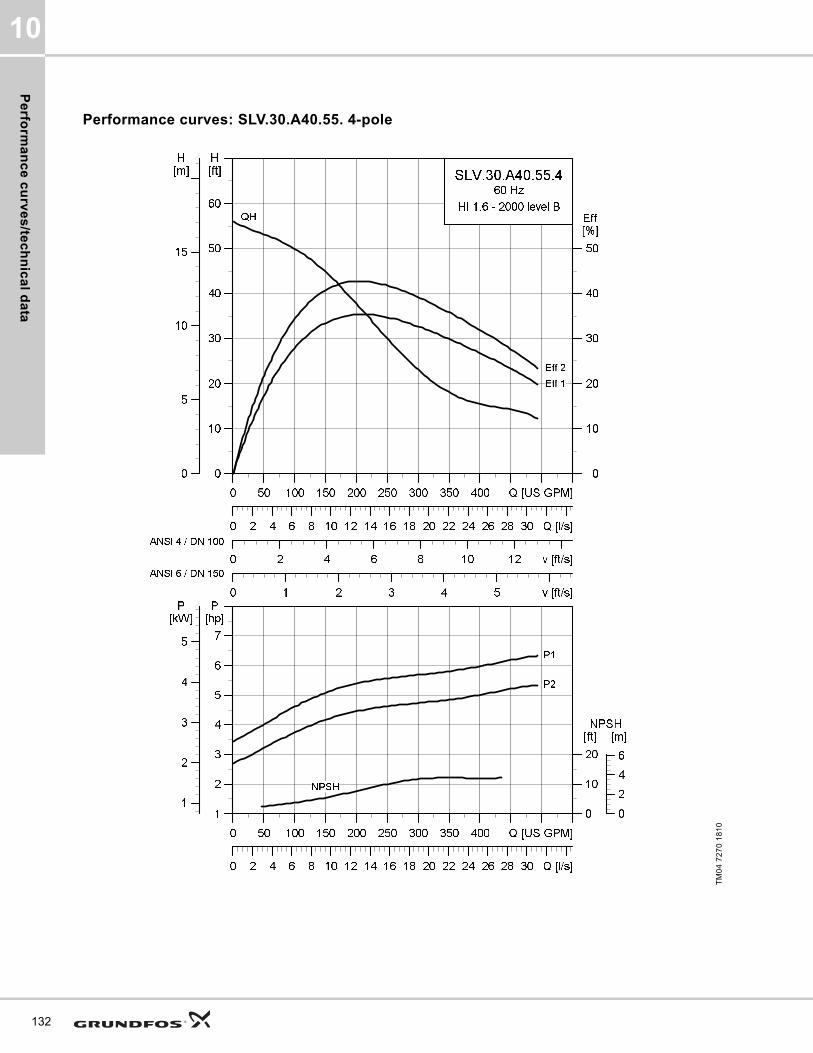
Pe
rform
an
ce
cu
rve
s/te
ch
nic
al d
ata
10
132
Performance curves: SLV.30.A40.55. 4-pole
TM
04
72
70
18
10
0 50 100 150 200 250 300 350 400 Q [US GPM]
0
10
20
30
40
50
60
[ft]H
0 2 4 6 8 10 12 v [ft/s]
0
10
20
30
40
50
[%]Eff
0 1 2 3 4 5 v [ft/s]
0 2 4 6 8 10 12 14 16 18 20 22 24 26 28 30 Q [l/s]
0
5
10
15
[m]H
SLV.30.A40.55.4
60 Hz
HI 1.6 - 2000 level B
Eff 2
Eff 1
QH
ANSI 4 / DN 100
ANSI 6 / DN 150
0 50 100 150 200 250 300 350 400 Q [US GPM]
1
2
3
4
5
6
7
[hp]P
0 2 4 6 8 10 12 14 16 18 20 22 24 26 28 30 Q [l/s]
0
10
20
[ft]NPSH
1
2
3
4
5
[kW]P
0
2
4
6
[m]
NPSH
P2
P1

Pe
rfo
rma
nc
e c
urv
es
/te
ch
nic
al
da
ta
10
Dimensional sketches: SLV.30.A40.55. 4-pole
Electrical data
Pump data
TM
04
27
93
30
08
/TM
04
27
94
30
08
/TM
04
27
95
30
08
A C D E F H DN1 Dc1 DØ1 D1n DN2 Dc2 DØ2 D2n Weight [lb/kg]
[inch] 29.3 18.4 7.9 11.3 15 4.3 3 6 8xM16 4 7.5 8x0.75 296.5
[mm] 744 466 200 286 380 109 80 152.4 8xM16 100 190.5 8x19.1 134.5
Z2 Z3 Z4 Z6 Z7 Z8 Z9 Z10 Z11 Z12a Z14 Z15 Z16 ZDN1 ZM
[inch] 10.2 4.3 8.7 35.8 26.9 19.8 4.3 2 34.5 0.03 0 8.7 16.3 4 4xM16
[mm] 260 110 220 909 683 503 110 2 876 131 0 220 413 100 4xM16
V1 V2 V3 V4 V5 V6 V7 VØ
[inch] 34.6 15.6 5.1 14 11.8 25.5 3.9 0.7
[mm] 878 395 130 355 300 647 100 18
Pump typeVoltage
[V]
P1 [hp] (kW)
P2 [hp] (kW)
No of poles
RPMStarting method
IN Istart ηmotor [%] Cos ϕ
SF
Moment of inertia
[lb*ft2
(kgm2)]
Breakdown torque Mmax
[lbf*ft (Nm)][A] [A] 1/2 3/4 1/1 1/2 3/4 1/1
SLV.30.A40.55.4.61J3x208-230V D
/ 460V Y6.4
(4.8)5.5 (4)
4 1760 SD 16.1 79.4 79.9 83.3 83.9 0.61 0.74 0.80 1.151.28
(0.054)81.58
(110.6)
SLV.30.A40.55.4.61L 3x575V D6.4
(4.8)5.5 (4)
4 1765 SD 6.5 37.5 79.2 83.3 84.7 0.54 0.67 0.75 1.151.28
(0.054)68.59 (93)
SLV.30.A40.55.4.61H 3x460V D6.4
(4.8)5.5 (4)
4 1770 SD 8.5 51.5 78.3 82.6 84.4 0.50 0.64 0.72 1.151.28
(0.054)74.49 (101)
Impeller type
Max. solids size
Pump housing pressure
Max. number of starts per hour
Max. installation depth
Enclosure class
Insulation class
Temperature rise class
Max. liquid temperature
pH
[Inch / mm] PN [Feet / m] [°F / °C]
SuperVortex 3 / 80 10 20 65 / 20 IP68 H A 104 / 40 4-14
133

Pe
rform
an
ce
cu
rve
s/te
ch
nic
al d
ata
10
134
Performance curves: SLV.30.A40.80
TM
04
72
71
18
10
0 50 100 150 200 250 300 350 Q [US GPM]
0
10
20
30
40
50
60
70
[ft]H
0 2 4 6 8 10 v [ft/s]
0
5
10
15
20
25
30
[%]Eff
0 1 2 3 4 5 v [ft/s]
0 2 4 6 8 10 12 14 16 18 20 22 24 26 28Q [l/s]
0
5
10
15
20
[m]H
SLV.30.A40.80.2
60 Hz
HI 1.6 - 2000 level B
Eff 2
Eff 1
QH
ANSI 4 / DN 100
ANSI 6 / DN 150
0 50 100 150 200 250 300 350 Q [US GPM]
3
4
5
6
7
8
9
[hp]P
0 2 4 6 8 10 12 14 16 18 20 22 24 26 28Q [l/s]
0
20
40
60
[ft]NPSH
3
4
5
6
[kW]P
0
5
10
15
[m]
NPSH
P2
P1

Pe
rfo
rma
nc
e c
urv
es
/te
ch
nic
al
da
ta
10
Dimensional sketches: SLV.30.A40.80
Electrical data
Pump data
TM
04
27
93
30
08
/TM
04
27
94
30
08
/TM
04
27
95
30
08
A C D E F H DN1 Dc1 DØ1 D1n DN2 Dc2 DØ2 D2n Weight [lb/kg]
[inch] 29.6 18.4 7.9 11.3 15 4.3 3 6 8xM16 4 7.5 8x0.75 307.5
[mm] 751 466 200 286 380 104 80 152.4 8xM16 100 190.5 8x19.1 139.5
Z2 Z3 Z4 Z6 Z7 Z8 Z9 Z10 Z11 Z12a Z14 Z15 Z16 ZDN1 ZM
[inch] 10.2 4.3 8.7 35.8 26.9 19.8 4.3 2 34.8 0.03 0 8.7 16.3 4 4xM16
[mm] 260 110 220 909 683 503 110 2 883 136 0 220 413 100 4xM16
V1 V2 V3 V4 V5 V6 V7 VØ
[inch] 34.6 13.9 5 13 11 23.5 3.9 0.7
[mm] 879 353 128 330 280 598 100 18
Pump typeVoltage
[V]
P1 [hp] (kW)
P2 [hp] (kW)
No of poles
RPMStarting method
IN Istart ηmotor [%] Cos ϕ
SF
Moment of inertia
[lb*ft2
(kgm2)]
Breakdown torque Mmax
[lbf*ft (Nm)][A] [A] 1/2 3/4 1/1 1/2 3/4 1/1
SLV.30.A40.80.2.61J3x208-230V D
/ 460V Y11.7 (8.7)
10 (7.5)
2 3520 SD 26.5 191 83 85.2 85.4 0.82 0.88 0.90 1.150.45
(0.019)71.1 (96.4)
SLV.30.A40.80.2.61L 3x575V D11.7 (8.7)
10 (7.5)
2 3525 SD 10.2 89 82.9 86 86.8 0.76 0.84 0.88 1.150.45
(0.019)59.74 (81)
SLV.30.A40.80.2.61H 3x460V D11.7 (8.7)
10 (7.5)
2 3550 SD 13.2 116 80.9 84.3 86.5 0.73 0.81 0.86 1.150.45
(0.019)65.64 (89)
Impeller type
Max. solids size
Pump housing pressure
Max. number of starts per hour
Max. installation depth
Enclosure class
Insulation class
Temperature rise class
Max. liquid temperature
pH
[Inch / mm] PN [Feet / m] [°F / °C]
SuperVortex 3 / 80 10 20 65 / 20 IP68 H B 104 / 40 4-14
135
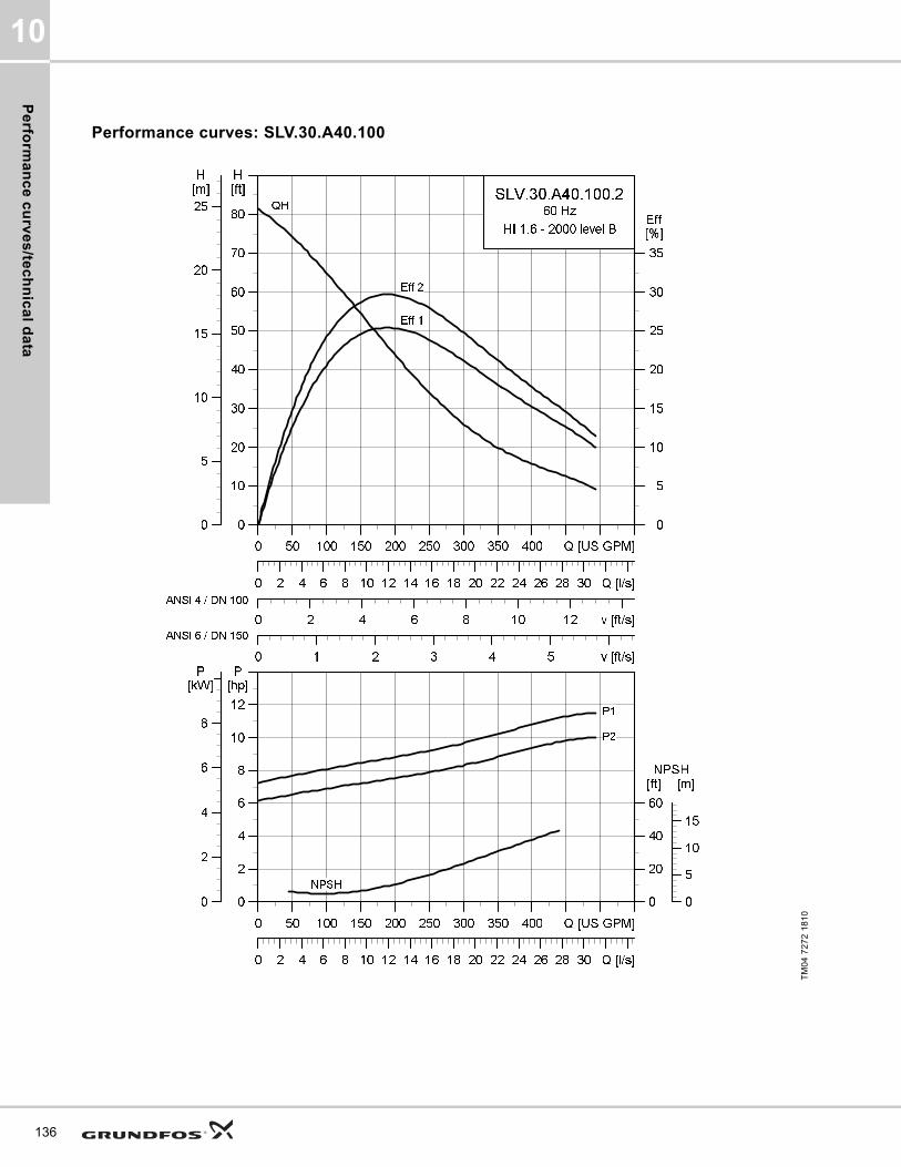
Pe
rform
an
ce
cu
rve
s/te
ch
nic
al d
ata
10
136
Performance curves: SLV.30.A40.100
TM
04
72
72
18
10
0 50 100 150 200 250 300 350 400 Q [US GPM]
0
10
20
30
40
50
60
70
80
[ft]H
0 2 4 6 8 10 12 v [ft/s]
0
5
10
15
20
25
30
35
[%]Eff
0 1 2 3 4 5 v [ft/s]
0 2 4 6 8 10 12 14 16 18 20 22 24 26 28 30 Q [l/s]
0
5
10
15
20
25
[m]H
SLV.30.A40.100.2
60 Hz
HI 1.6 - 2000 level B
Eff 2
Eff 1
QH
ANSI 4 / DN 100
ANSI 6 / DN 150
0 50 100 150 200 250 300 350 400 Q [US GPM]
0
2
4
6
8
10
12
[hp]P
0 2 4 6 8 10 12 14 16 18 20 22 24 26 28 30 Q [l/s]
0
20
40
60
[ft]NPSH
0
2
4
6
8
[kW]P
0
5
10
15
[m]
NPSH
P2
P1

Pe
rfo
rma
nc
e c
urv
es
/te
ch
nic
al
da
ta
10
Dimensional sketches: SLV.30.A40.100
Electrical data
Pump data
TM
04
27
93
30
08
/TM
04
27
94
30
08
/TM
04
27
95
30
08
A C D E F H DN1 Dc1 DØ1 D1n DN2 Dc2 DØ2 D2n Weight [lb/kg]
[inch] 30.8 19.7 8.5 12 16.3 4.8 3 6 8xM16 4 7.5 8x0.75 308
[mm] 782 499 217 303 413 104 80 152.4 8xM16 100 190.5 8x19.1 139.7
Z2 Z3 Z4 Z6 Z7 Z8 Z9 Z10 Z11 Z12a Z14 Z15 Z16 ZDN1 ZM
[inch] 10.2 4.3 8.7 37.1 28.2 20.5 4.3 2 35.4 0.03 0 8.7 16.3 4 4xM16
[mm] 260 110 220 942 716 520 110 2 899 136 0 220 413 100 4xM16
V1 V2 V3 V4 V5 V6 V7 VØ
[inch] 34.6 13.9 5 13 11 23.5 3.9 0.7
[mm] 879 353 128 330 280 598 100 18
Pump typeVoltage
[V]
P1 [hp] (kW)
P2 [hp] (kW)
No
of
po
les
RPMStarting method
IN Istart ηmotor [%] Cos ϕ
SF
Moment of inertia
[lb*ft2
(kgm2)]
Breakdown torque Mmax
[lbf*ft (Nm)][A] [A] 1/2 3/4 1/1 1/2 3/4 1/1
SLV.30.A40.100.2.61J3x208-230V D
/ 460V Y11.7 (8.7)
10 (7.5)
2 3520 SD 26.5 191 83 85.2 85.4 0.82 0.88 0.9 1.150.52
(0.022)71.1 (96.4)
SLV.30.A40.100.2.61L 3x575V D11.7 (8.7)
10 (7.5)
2 3525 SD 10.2 89 82.9 86 86.8 0.76 0.84 0.88 1.150.52
(0.022)59.74 (81)
SLV.30.A40.100.2.61H 3x460V D11.7 (8.7)
10 (7.5)
2 3550 SD 13.2 116 80.9 84.4 85.5 0.73 0.81 0.86 1.150.52
(0.022)65.64 (89)
Impeller type
Max. solids size
Pump housing pressure
Max. number of starts per hour
Max. installation depth
Enclosure class
Insulation class
Temperature rise class
Max. liquid temperature
pH
[Inch / mm] PN [Feet / m] [°F / °C]
SuperVortex 3 / 80 10 20 65 / 20 IP68 H B 104 / 40 4-14
137
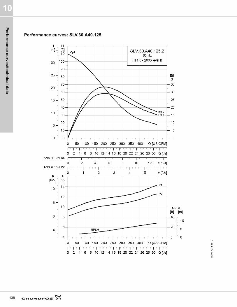
Pe
rform
an
ce
cu
rve
s/te
ch
nic
al d
ata
10
138
Performance curves: SLV.30.A40.125
TM
04
72
73
18
10
0 50 100 150 200 250 300 350 400 Q [US GPM]
0
10
20
30
40
50
60
70
80
90
100
110
[ft]H
0 2 4 6 8 10 12 v [ft/s]
0
5
10
15
20
25
30
35
[%]Eff
0 1 2 3 4 5 v [ft/s]
0 2 4 6 8 10 12 14 16 18 20 22 24 26 28 30 Q [l/s]
0
5
10
15
20
25
30
[m]H
SLV.30.A40.125.2
60 Hz
HI 1.6 - 2000 level B
Eff 2
Eff 1
QH
ANSI 4 / DN 100
ANSI 6 / DN 150
0 50 100 150 200 250 300 350 400 Q [US GPM]
4
6
8
10
12
14
[hp]P
0 2 4 6 8 10 12 14 16 18 20 22 24 26 28 30 Q [l/s]
0
20
40
[ft]NPSH
4
6
8
10
[kW]P
0
5
10
[m]
NPSH
P2
P1

Pe
rfo
rma
nc
e c
urv
es
/te
ch
nic
al
da
ta
10
Dimensional sketches: SLV.30.A40.125
Electrical data
Pump data
* SLV.30.A40.125.2.61H are temperature rise class B
TM
04
27
93
30
08
/TM
04
27
94
30
08
/TM
04
27
95
30
08
A C D E F H DN1 Dc1 DØ1 D1n DN2 Dc2 DØ2 D2n Weight [lb/kg]
[inch] 30.8 19.7 8.5 12 16.3 4.8 3 6 8xM16 4 7.5 8x0.75 401.5
[mm] 782 499 217 303 413 123 80 152.4 8xM16 100 190.5 8x19.1 182.1
Z2 Z3 Z4 Z6 Z7 Z8 Z9 Z10 Z11 Z12a Z14 Z15 Z16 ZDN1 ZM
[inch] 10.2 4.3 8.7 37.1 28.2 20.5 4.3 2 35.4 0.03 0 8.7 16.3 4 4xM16
[mm] 260 110 220 942 716 520 110 2 899 117 0 220 413 100 4xM16
V1 V2 V3 V4 V5 V6 V7 VØ
[inch] 35.8 14.5 5 13 11 25.2 3.9 0.7
[mm] 910 368 128 330 280 641 100 18
Pump typeVoltage
[V]
P1 [hp] (kW)
P2 [hp] (kW)
No
of
po
les
RPMStarting method
IN Istart ηmotor [%] Cos ϕ
SF
Moment of inertia
[lb*ft2
(kgm2)]
Breakdown torque Mmax [lbf*ft (Nm)]
[A] [A] 1/2 3/4 1/1 1/2 3/4 1/1
SLV.30.A40.125.2.61J3x208-230V D
/ 460V Y17
(12.7)15
(11)2 3545 SD 38.2 251 85.6 87.3 87 0.84 0.89 0.90 1.15
1.21 (0.051)
79.66 (108)
SLV.30.A40.125.2.61L 3x575V D17
(12.7)15
(11)2 3550 SD 14.5 115 85.8 88.1 88.5 0.80 0.86 0.89 1.15
1.21 (0.051)
67.12 (91)
SLV.30.A40.125.2.61H 3x460V D17
(12.7)15
(11)2 3550 SD 18.2 157 85.9 88.1 88.7 0.77 0.85 0.88 1.15
1.21 (0.051)
73.02 (99)
Impeller type
Max. solids size
Pump housing pressure
Max. number of starts per hour
Max. installation depth
Enclosure class
Insulation class
Temperature rise class
Max. liquid temperature
pH
[Inch / mm] PN [Feet / m] [°F / °C]
SuperVortex 3 / 80 10 20 65 / 20 IP68 H A (B)* 104 / 40 4-14
139
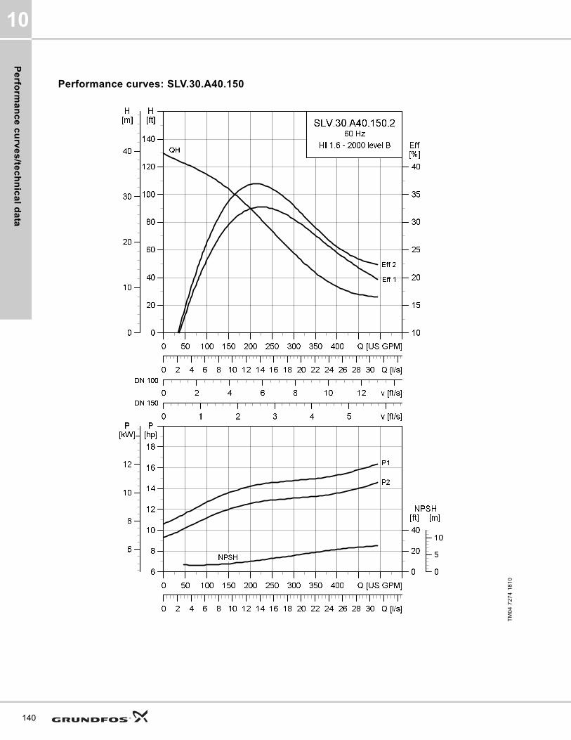
Pe
rform
an
ce
cu
rve
s/te
ch
nic
al d
ata
10
140
Performance curves: SLV.30.A40.150
TM
04
72
74
18
10
0 50 100 150 200 250 300 350 400 Q [US GPM]
0
20
40
60
80
100
120
140
[ft]H
0 2 4 6 8 10 12 v [ft/s]
10
15
20
25
30
35
40
[%]Eff
0 1 2 3 4 5 v [ft/s]
0 2 4 6 8 10 12 14 16 18 20 22 24 26 28 30 Q [l/s]
0
10
20
30
40
[m]H
SLV.30.A40.150.2
60 Hz
HI 1.6 - 2000 level B
Eff 2
Eff 1
QH
DN 100
DN 150
0 50 100 150 200 250 300 350 400 Q [US GPM]
6
8
10
12
14
16
18
[hp]P
0 2 4 6 8 10 12 14 16 18 20 22 24 26 28 30 Q [l/s]
0
20
40
[ft]NPSH
6
8
10
12
[kW]P
0
5
10
[m]
NPSH
P2
P1
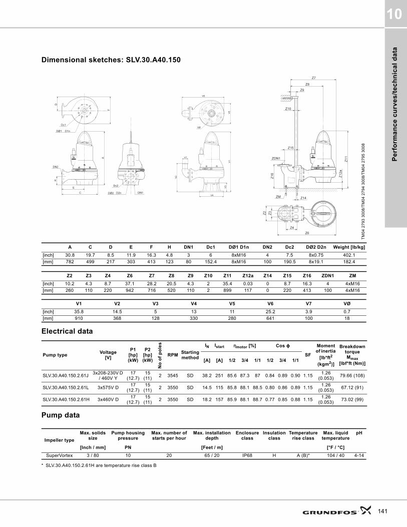
Pe
rfo
rma
nc
e c
urv
es
/te
ch
nic
al
da
ta
10
Dimensional sketches: SLV.30.A40.150
Electrical data
Pump data
* SLV.30.A40.150.2.61H are temperature rise class B
TM
04
27
93
30
08
/TM
04
27
94
30
08
/TM
04
27
95
30
08
A C D E F H DN1 Dc1 DØ1 D1n DN2 Dc2 DØ2 D2n Weight [lb/kg]
[inch] 30.8 19.7 8.5 11.9 16.3 4.8 3 6 8xM16 4 7.5 8x0.75 402.1
[mm] 782 499 217 303 413 123 80 152.4 8xM16 100 190.5 8x19.1 182.4
Z2 Z3 Z4 Z6 Z7 Z8 Z9 Z10 Z11 Z12a Z14 Z15 Z16 ZDN1 ZM
[inch] 10.2 4.3 8.7 37.1 28.2 20.5 4.3 2 35.4 0.03 0 8.7 16.3 4 4xM16
[mm] 260 110 220 942 716 520 110 2 899 117 0 220 413 100 4xM16
V1 V2 V3 V4 V5 V6 V7 VØ
[inch] 35.8 14.5 5 13 11 25.2 3.9 0.7
[mm] 910 368 128 330 280 641 100 18
Pump typeVoltage
[V]
P1 [hp] (kW)
P2 [hp] (kW)
No
of
po
les
RPMStarting method
IN Istart ηmotor [%] Cos ϕ
SF
Moment of inertia
[lb*ft2
(kgm2)]
Breakdown torque Mmax
[lbf*ft (Nm)][A] [A] 1/2 3/4 1/1 1/2 3/4 1/1
SLV.30.A40.150.2.61J3x208-230V D
/ 460V Y17
(12.7)15
(11)2 3545 SD 38.2 251 85.6 87.3 87 0.84 0.89 0.90 1.15
1.26 (0.053)
79.66 (108)
SLV.30.A40.150.2.61L 3x575V D17
(12.7)15
(11)2 3550 SD 14.5 115 85.8 88.1 88.5 0.80 0.86 0.89 1.15
1.26 (0.053)
67.12 (91)
SLV.30.A40.150.2.61H 3x460V D17
(12.7)15
(11)2 3550 SD 18.2 157 85.9 88.1 88.7 0.77 0.85 0.88 1.15
1.26 (0.053)
73.02 (99)
Impeller type
Max. solids size
Pump housing pressure
Max. number of starts per hour
Max. installation depth
Enclosure class
Insulation class
Temperature rise class
Max. liquid temperature
pH
[Inch / mm] PN [Feet / m] [°F / °C]
SuperVortex 3 / 80 10 20 65 / 20 IP68 H A (B)* 104 / 40 4-14
141
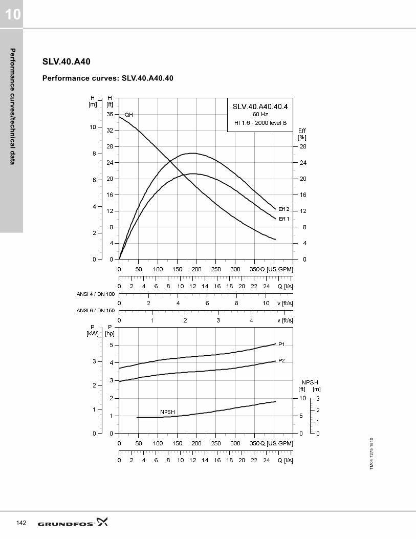
Pe
rform
an
ce
cu
rve
s/te
ch
nic
al d
ata
10
142
SLV.40.A40
Performance curves: SLV.40.A40.40
TM
04
72
75
18
10
0 50 100 150 200 250 300 350 Q [US GPM]
0
4
8
12
16
20
24
28
32
36
[ft]H
0 2 4 6 8 10 v [ft/s]
0
4
8
12
16
20
24
28
[%]Eff
0 1 2 3 4 v [ft/s]
0 2 4 6 8 10 12 14 16 18 20 22 24 Q [l/s]
0
2
4
6
8
10
[m]H
SLV.40.A40.40.4
60 Hz
HI 1.6 - 2000 level B
Eff 2
Eff 1
QH
ANSI 4 / DN 100
ANSI 6 / DN 150
0 50 100 150 200 250 300 350 Q [US GPM]
0
1
2
3
4
5
[hp]P
0 2 4 6 8 10 12 14 16 18 20 22 24 Q [l/s]
0
5
10
[ft]NPSH
0
1
2
3
[kW]P
0
1
2
3
[m]
NPSH
P2
P1

Pe
rfo
rma
nc
e c
urv
es
/te
ch
nic
al
da
ta
10
Dimensional sketches: SLV.40.A40.40
Electrical data
Pump data
TM
04
27
93
30
08
/TM
04
27
94
30
08
/TM
04
27
95
30
08
A C D E F H DN1 Dc1 DØ1 D1n DN2 Dc2 DØ2 D2n Weight [lb/kg]
[inch] 29 18 7.9 10.9 15 5.3 4 7.5 8xM16 4 7.5 8x0.75 274.5
[mm] 737 457 200 277 380 134 100 190.5 8xM16 100 190.5 8x19.1 124.5
Z2 Z3 Z4 Z6 Z7 Z8 Z9 Z10 Z11 Z12a Z14 Z15 Z16 ZDN1 ZM
[inch] 10.2 4.3 8.7 35.4 26.5 19.5 4.3 2 33.2 0.03 0 8.7 16.3 4 4xM16
[mm] 260 110 220 900 674 494 110 2 844 106 0 220 413 100 4xM16
V1 V2 V3 V4 V5 V6 V7 VØ
[inch] 34.1 16.2 5.1 14 11.8 23.6 3.9 0.8
[mm] 867 411 130 355 300 599 100 19
Pump typeVoltage
[V]
P1 [hp] (kW)
P2 [hp] (kW)
No of poles
RPMStarting method
IN Istart ηmotor [%] Cos ϕ
SF
Moment of inertia
[lb*ft2
(kgm2)]
Breakdown torque Mmax
[lbf*ft (Nm)][A] [A] 1/2 3/4 1/1 1/2 3/4 1/1
SLV.40.A40.40.4.61J3x208-230V D
/ 460V Y5
(3.7)4 (3) 4 1760 SD 12 79.5 76 79.8 80.2 0.69 0.80 0.84 1.15
1.11 (0.0469)
38.35 (52)
SLV.40.A40.40.4.61L 3x575V D5
(3.7)4 (3) 4 1750 SD 4.8 37.5 75 79.4 81.4 0.61 0.72 0.80 1.15
1.11 (0.0469)
46.47 (63)
SLV.40.A40.40.4.61H 3x460V D5
(3.7)4 (3) 4 1760 SD 6.2 51.5 74.6 79.7 81.5 0.56 0.68 0.77 1.15
1.11 (0.0469)
50.89 (69)
Impeller type
Max. solids size
Pump housing pressure
Max. number of starts per hour
Max. installation depth
Enclosure class
Insulation class
Temperature rise class
Max. liquid temperature
pH
[Inch / mm] PN [Feet / m] [°F / °C]
SuperVortex 4 / 100 10 20 65 / 20 IP68 H A 104 / 40 4-14
143
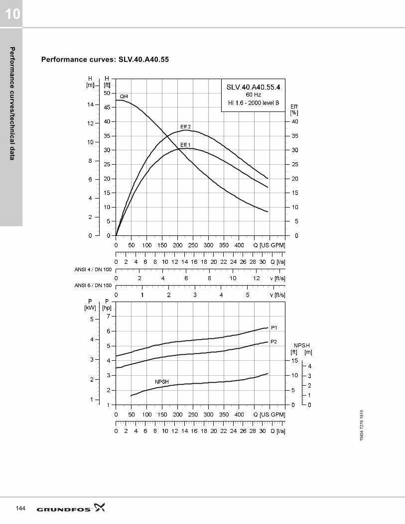
Pe
rform
an
ce
cu
rve
s/te
ch
nic
al d
ata
10
144
Performance curves: SLV.40.A40.55
TM
04
72
76
18
10
0 50 100 150 200 250 300 350 400 Q [US GPM]
0
5
10
15
20
25
30
35
40
45
50
[ft]H
0 2 4 6 8 10 12 v [ft/s]
0
5
10
15
20
25
30
35
40
[%]Eff
0 1 2 3 4 5 v [ft/s]
0 2 4 6 8 10 12 14 16 18 20 22 24 26 28 30 Q [l/s]
0
2
4
6
8
10
12
14
[m]H
SLV.40.A40.55.4
60 Hz
HI 1.6 - 2000 level B
Eff 2
Eff 1
QH
ANSI 4 / DN 100
ANSI 6 / DN 150
0 50 100 150 200 250 300 350 400 Q [US GPM]
1
2
3
4
5
6
7
[hp]P
0 2 4 6 8 10 12 14 16 18 20 22 24 26 28 30 Q [l/s]
0
5
10
15
[ft]NPSH
1
2
3
4
5
[kW]P
0
1
2
3
4
[m]
NPSH
P2
P1

Pe
rfo
rma
nc
e c
urv
es
/te
ch
nic
al
da
ta
10
Dimensional sketches: SLV.40.A40.55
Electrical data
Pump data
TM
04
27
93
30
08
/TM
04
27
94
30
08
/TM
04
27
95
30
08
A C D E F H DN1 Dc1 DØ1 D1n DN2 Dc2 DØ2 D2n Weight [lb/kg]
[inch] 29.9 18 7.9 10.9 15 5.3 4 7.5 8xM16 4 7.5 8x0.75 283.7
[mm] 759 457 200 277 380 134 100 190.5 8xM16 100 190.5 8x19.1 128.7
Z2 Z3 Z4 Z6 Z7 Z8 Z9 Z10 Z11 Z12a Z14 Z15 Z16 ZDN1 ZM
[inch] 10.2 4.3 8.7 35.4 26.5 19.5 4.3 2 34.1 0.03 0 8.7 16.3 4 4xM16
[mm] 260 110 220 900 674 494 110 2 866 106 0 220 413 100 4xM16
V1 V2 V3 V4 V5 V6 V7 VØ
[inch] 35 16.2 5.1 14 11.8 23.6 3.9 0.8
[mm] 889 411 130 355 300 599 100 19
Pump typeVoltage
[V]
P1 [hp] (kW)
P2 [hp] (kW)
No of poles
RPMStarting method
IN Istart ηmotor [%] Cos ϕ
SF
Moment of inertia
[lb*ft2
(kgm2)]
Breakdown torque Mmax
[lbf*ft (Nm)][A] [A] 1/2 3/4 1/1 1/2 3/4 1/1
SLV.40.A40.55.4.61J3x208-230V D
/ 460V Y6.4
(4.8)5.5 (4)
4 1760 SD 16.1 79.4 79.9 83.3 83.9 0.61 0.74 0.80 1.151.31
(0.055)81.58
(110.6)
SLV.40.A40.55.4.61L 3x575V D6.4
(4.8)5.5 (4)
4 1765 SD 6.5 37.5 79.2 83.3 84.7 0.54 0.67 0.75 1.151.31
(0.055)68.59 (93)
SLV.40.A40.55.4.61H 3x460V D6.4
(4.8)5.5 (4)
4 1770 SD 8.5 51.5 78.3 82.6 84.4 0.50 0.64 0.72 1.151.31
(0.055)74.49 (101)
Impeller type
Max. solids size
Pump housing pressure
Max. number of starts per hour
Max. installation depth
Enclosure class
Insulation class
Temperature rise class
Max. liquid temperature
pH
[Inch / mm] PN [Feet / m] [°F / °C]
SuperVortex 4 / 100 10 20 65 / 20 IP68 H A 104 / 40 4-14
145
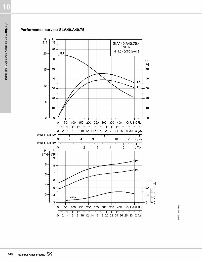
Pe
rform
an
ce
cu
rve
s/te
ch
nic
al d
ata
10
146
Performance curves: SLV.40.A40.75
TM
04
72
77
18
10
0 50 100 150 200 250 300 350 400 Q [US GPM]
0
10
20
30
40
50
60
70
[ft]H
0 2 4 6 8 10 12 v [ft/s]
0
10
20
30
40
50
[%]Eff
0 1 2 3 4 5 v [ft/s]
0 2 4 6 8 10 12 14 16 18 20 22 24 26 28 30 Q [l/s]
0
5
10
15
20
[m]H
SLV.40.A40.75.4
60 Hz
HI 1.6 - 2000 level B
Eff 2
Eff 1
QH
ANSI 4 / DN 100
ANSI 6 / DN 150
0 50 100 150 200 250 300 350 400 Q [US GPM]
3
4
5
6
7
8
9
[hp]P
0 2 4 6 8 10 12 14 16 18 20 22 24 26 28 30 Q [l/s]
0
10
20
[ft]NPSH
0
2
4
6
[m]
3
4
5
6
[kW]P
NPSH
P2
P1

Pe
rfo
rma
nc
e c
urv
es
/te
ch
nic
al
da
ta
10
Dimensional sketches: SLV.40.A40.75
Electrical data
Pump data
TM
04
27
93
30
08
/TM
04
27
94
30
08
/TM
04
27
95
30
08
A C D E F H DN1 Dc1 DØ1 D1n DN2 Dc2 DØ2 D2n Weight [lb/kg]
[inch] 30.2 18 7.9 10.9 15 5.3 4 7.5 8xM16 4 7.5 8x0.75 297.8
[mm] 766 457 200 277 380 134 100 190.5 8xM16 100 190.5 8x19.1 135.1
Z2 Z3 Z4 Z6 Z7 Z8 Z9 Z10 Z11 Z12a Z14 Z15 Z16 ZDN1 ZM
[inch] 10.2 4.3 8.7 35.4 26.5 19.5 4.3 2 34.4 0.03 0 8.7 16.3 4 4xM16
[mm] 260 110 220 900 674 494 110 2 873 106 0 220 413 100 4xM16
V1 V2 V3 V4 V5 V6 V7 VØ
[inch] 35.3 16.2 5.1 14 11.8 23.6 3.9 0.8
[mm] 896 411 130 355 300 599 100 19
Pump typeVoltage
[V]
P1 [hp] (kW)
P2 [hp] (kW)
No of poles
RPMStarting method
IN Istart ηmotor [%] Cos ϕ
SF
Moment of inertia
[lb*ft2
(kgm2)]
Breakdown torque Mmax
[lbf*ft (Nm)][A] [A] 1/2 3/4 1/1 1/2 3/4 1/1
SLV.40.A40.75.4.61J3x208-230V D
/ 460V Y8.6
(6.4)7.5
(5.5)4 1760 SD 20 126 83.2 85.6 85.8 0.77 0.84 0.87 1.15
1.58 (0.06656)
90.41 (122.6)
SLV.40.A40.75.4.61L 3x575V D8.6
(6.4)7.5
(5.5)4 1765 SD 7.8 59.3 83.5 86.6 87.3 0.69 0.79 0.84 1.15
1.58 (0.06656)
75.97 (103)
SLV.40.A40.75.4.61H 3x460V D8.6
(6.4)7.5
(5.5)4 1770 SD 10 81.4 82.9 86.3 87.2 0.65 0.75 0.81 1.15
1.58 (0.06656)
83.34 (113)
Impeller type
Max. solids size
Pump housing pressure
Max. number of starts per hour
Max. installation depth
Enclosure class
Insulation class
Temperature rise class
Max. liquid temperature
pH
[Inch / mm] PN [Feet / m] [°F / °C]
SuperVortex 4 / 100 10 20 65 / 20 IP68 H A 104 / 40 4-14
147
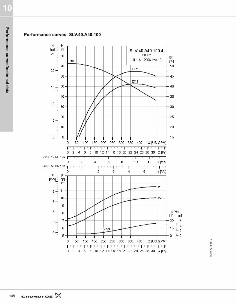
Pe
rform
an
ce
cu
rve
s/te
ch
nic
al d
ata
10
148
Performance curves: SLV.40.A40.100
TM
04
72
78
18
10
0 50 100 150 200 250 300 350 400 Q [US GPM]
0
10
20
30
40
50
60
70
80
[ft]H
0 2 4 6 8 10 12 v [ft/s]
15
20
25
30
35
40
45
50
[%]Eff
0 1 2 3 4 5 v [ft/s]
0 2 4 6 8 10 12 14 16 18 20 22 24 26 28 30 Q [l/s]
0
5
10
15
20
25
[m]H
SLV.40.A40.100.4
60 Hz
HI 1.6 - 2000 level B
Eff 2
Eff 1
QH
ANSI 4 / DN 100
ANSI 6 / DN 150
0 50 100 150 200 250 300 350 400 Q [US GPM]
5
6
7
8
9
10
11
12
[hp]P
0 2 4 6 8 10 12 14 16 18 20 22 24 26 28 30 Q [l/s]
0
10
20
[ft]NPSH
4
5
6
7
8
[kW]P
0
2
4
6
[m]
NPSH
P2
P1

Pe
rfo
rma
nc
e c
urv
es
/te
ch
nic
al
da
ta
10
Dimensional sketches: SLV.40.A40.100
Electrical data
Pump data
TM
04
27
93
30
08
/TM
04
27
94
30
08
/TM
04
27
95
30
08
A C D E F H DN1 Dc1 DØ1 D1n DN2 Dc2 DØ2 D2n Weight [lb/kg]
[inch] 33.2 19.3 8.5 11.6 16.3 5.7 4 7.5 8xM16 4 7.5 8x0.75 391.5
[mm] 842 490 217 294 413 145 100 190.5 8xM16 100 190.5 8x19.1 177.6
Z2 Z3 Z4 Z6 Z7 Z8 Z9 Z10 Z11 Z12a Z14 Z15 Z16 ZDN1 ZM
[inch] 10.2 4.3 8.7 36.7 27.8 20.1 4.3 2 36.9 0.03 0 8.7 16.3 4 4xM16
[mm] 260 110 220 933 707 511 110 2 938 96 0 220 413 100 4xM16
V1 V2 V3 V4 V5 V6 V7 VØ
[inch] 38.3 16.6 5.1 14 11.8 24.9 3.9 0.8
[mm] 972 422 130 355 300 632 100 19
Pump typeVoltage
[V]
P1 [hp] (kW)
P2 [hp] (kW)
No
of
po
les
RPMStarting method
IN Istart ηmotor [%] Cos ϕ
SF
Moment of inertia
[lb*ft2
(kgm2)]
Breakdown torque Mmax
[lbf*ft (Nm)][A] [A] 1/2 3/4 1/1 1/2 3/4 1/1
SLV.40.A40.100.4.61J3x208-230V D
/ 460V Y11.5 (8.6)
10 (7.5)
4 1760 SD 26.6 174 85.6 86.9 86.4 0.80 0.86 0.89 1.151.92
(0.081)75.23 (102)
SLV.40.A40.100.4.61L 3x575V D11.5 (8.6)
10 (7.5)
4 1760 SD 10.2 81.2 85.3 87.4 87.9 0.74 0.83 0.86 1.151.92
(0.081)104.73 (142)
SLV.40.A40.100.4.61H 3x460V D11.5 (8.6)
10 (7.5)
4 1765 SD 13 111 85 87.6 88.1 0.70 0.80 0.85 1.151.92
(0.081)114.32 (155)
Impeller type
Max. solids size
Pump housing pressure
Max. number of starts per hour
Max. installation depth
Enclosure class
Insulation class
Temperature rise class
Max. liquid temperature
pH
[Inch / mm] PN [Feet / m] [°F / °C]
SuperVortex 4 / 100 10 20 65 / 20 IP68 H A 104 / 40 4-14
149
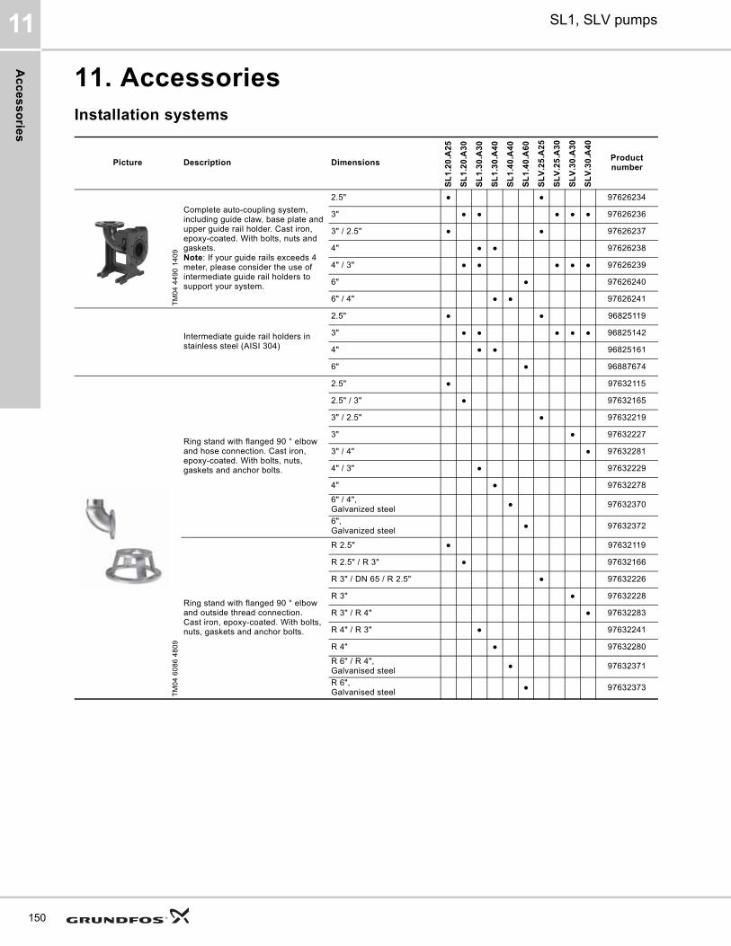
Ac
ce
ss
orie
s
SL1, SLV pumps11
150
11. AccessoriesInstallation systems
Picture Description Dimensions
SL
1.2
0.A
25
SL
1.2
0.A
30
SL
1.3
0.A
30
SL
1.3
0.A
40
SL
1.4
0.A
40
SL
1.4
0.A
60
SL
V.2
5.A
25
SL
V.2
5.A
30
SL
V.3
0.A
30
SL
V.3
0.A
40
Product number
TM
04
44
90
14
09
Complete auto-coupling system, including guide claw, base plate and upper guide rail holder. Cast iron, epoxy-coated. With bolts, nuts and gaskets.Note: If your guide rails exceeds 4 meter, please consider the use of intermediate guide rail holders to support your system.
2.5" ● ● 97626234
3" ● ● ● ● ● 97626236
3" / 2.5" ● ● 97626237
4" ● ● 97626238
4" / 3" ● ● ● ● ● 97626239
6" ● 97626240
6" / 4" ● ● 97626241
Intermediate guide rail holders in stainless steel (AISI 304)
2.5" ● ● 96825119
3" ● ● ● ● ● 96825142
4" ● ● 96825161
6" ● 96887674
TM
04
60
86
48
09
Ring stand with flanged 90 ° elbow and hose connection. Cast iron, epoxy-coated. With bolts, nuts, gaskets and anchor bolts.
2.5" ● 97632115
2.5" / 3" ● 97632165
3" / 2.5" ● 97632219
3" ● 97632227
3" / 4" ● 97632281
4" / 3" ● 97632229
4" ● 97632278
6" / 4", Galvanized steel
● 97632370
6", Galvanized steel
● 97632372
Ring stand with flanged 90 ° elbow and outside thread connection. Cast iron, epoxy-coated. With bolts, nuts, gaskets and anchor bolts.
R 2.5" ● 97632119
R 2.5" / R 3" ● 97632166
R 3" / DN 65 / R 2.5" ● 97632226
R 3" ● 97632228
R 3" / R 4" ● 97632283
R 4" / R 3" ● 97632241
R 4" ● 97632280
R 6" / R 4", Galvanised steel
● 97632371
R 6", Galvanised steel
● 97632373
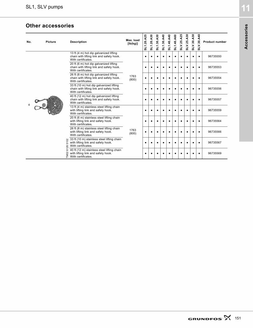
Ac
ce
ss
ori
es
SL1, SLV pumps 11
Other accessories
No. Picture DescriptionMax. load
[lb(kg)]
SL
1.2
0.A
25
SL
1.2
0.A
30
SL
1.3
0.A
30
SL
1.3
0.A
40
SL
1.4
0.A
40
SL
1.4
0.A
60
SL
V.2
5.A
25
SL
V.2
5.A
30
SL
V.3
0.A
30
SL
V.3
0.A
40
Product number
4
TM
02
61
26
51
02
13 ft (4 m) hot dip galvanized lifting chain with lifting link and safety hook.With certificates.
1763(800)
● ● ● ● ● ● ● ● ● ● 96735550
20 ft (6 m) hot dip galvanized lifting chain with lifting link and safety hook. With certificates.
● ● ● ● ● ● ● ● ● ● 96735553
26 ft (8 m) hot dip galvanized lifting chain with lifting link and safety hook.With certificates.
● ● ● ● ● ● ● ● ● ● 96735554
33 ft (10 m) hot dip galvanized lifting chain with lifting link and safety hook.With certificates.
● ● ● ● ● ● ● ● ● ● 96735556
40 ft (12 m) hot dip galvanized lifting chain with lifting link and safety hook.With certificates.
● ● ● ● ● ● ● ● ● ● 96735557
13 ft (4 m) stainless steel lifting chain with lifting link and safety hook. With certificates.
1763(800)
● ● ● ● ● ● ● ● ● ● 96735559
20 ft (6 m) stainless steel lifting chain with lifting link and safety hook. With certificates.
● ● ● ● ● ● ● ● ● ● 96735564
26 ft (8 m) stainless steel lifting chain with lifting link and safety hook. With certificates.
● ● ● ● ● ● ● ● ● ● 96735566
33 ft (10 m) stainless steel lifting chain with lifting link and safety hook.With certificates.
● ● ● ● ● ● ● ● ● ● 96735567
40 ft (12 m) stainless steel lifting chain with lifting link and safety hook. With certificates.
● ● ● ● ● ● ● ● ● ● 96735569
151
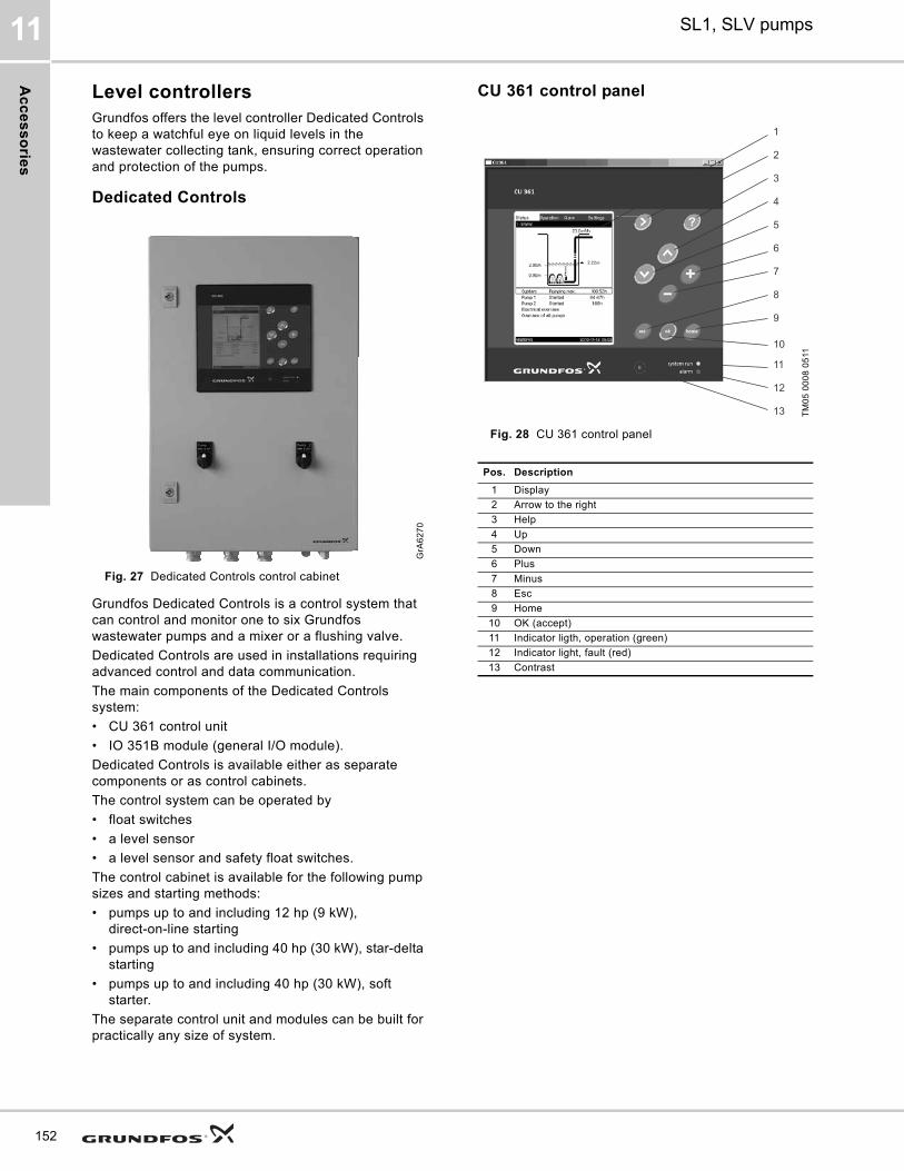
Ac
ce
ss
orie
s
SL1, SLV pumps11
152
Level controllersGrundfos offers the level controller Dedicated Controls to keep a watchful eye on liquid levels in the wastewater collecting tank, ensuring correct operation and protection of the pumps.
Dedicated Controls
Fig. 27 Dedicated Controls control cabinet
Grundfos Dedicated Controls is a control system that can control and monitor one to six Grundfos wastewater pumps and a mixer or a flushing valve.
Dedicated Controls are used in installations requiring advanced control and data communication.
The main components of the Dedicated Controls system:
• CU 361 control unit
• IO 351B module (general I/O module).
Dedicated Controls is available either as separate components or as control cabinets.
The control system can be operated by
• float switches
• a level sensor
• a level sensor and safety float switches.
The control cabinet is available for the following pump sizes and starting methods:
• pumps up to and including 12 hp (9 kW), direct-on-line starting
• pumps up to and including 40 hp (30 kW), star-delta starting
• pumps up to and including 40 hp (30 kW), soft starter.
The separate control unit and modules can be built for practically any size of system.
CU 361 control panel
Fig. 28 CU 361 control panelG
rA6
27
0
TM
05
00
08
05
11
Pos. Description
1 Display
2 Arrow to the right
3 Help
4 Up
5 Down
6 Plus
7 Minus
8 Esc
9 Home
10 OK (accept)
11 Indicator ligth, operation (green)
12 Indicator light, fault (red)
13 Contrast
3
2
1
4
5
6
7
8
9
10
11
12
13

Ac
ce
ss
ori
es
SL1, SLV pumps 11
Menu Status
Fig. 29 Menu Status
Description
• Graphical illustration of system (upper display half).
• Clear text parameters.
• Indication of alarms that occur during operation (top and middle of display).
• Reading of performance of system and individual pumps (lower display half).
• Button for further information.
• Active buttons are illuminated.
Menu Operation
Fig. 30 Menu operation
Description
• Setting of basic parameters, for instance start/stop levels,
• Setting of auto/on/off of system or individual pumps.
• Resetting of alarm relays.
• Button for further information
• Active buttons are illuminated.
Menu Alarm
Fig. 31 Menu Alarm
Description
• Current alarm – and alarm log with detailed information:-What the cause of the fault is.-Where the fault occurred: System, Pump no. 1…-When the fault occurred (time and date).-When the fault disappeared (time and date).
• Alarm snapshot – reading of system and pump parameters at the time of alarm
• Alarm log with up to 24 historical warnings and alarms.
• Button for further information.
• Active buttons are illuminated.
Menu Settings
Fig. 32 Menu Settings
Description
• Various settings:-Setting of analogue/digital inputs and outputs-Setting of application optimised functions such as energy optimisation, foam drainage and advanced alternation-display language-Communication settings-Ethernet, etc.
• Button for further information.
• Active buttons are illuminated.
TM
05
00
09
05
11T
M0
5 0
01
0 0
511
TM
05
00
11 0
511
TM
05
00
12
05
11
153
Ac
ce
ss
orie
s
SL1, SLV pumps11
154
The Dedicated Control cabinets can be fitted with various units:
• The CU 361 control unit, which is the 'brain' of the Dedicated Controls system, is fitted in the cabinet front. The CU 361 can be fitted with one of the Grundfos CIM communication modules mentioned below, depending on the monitoring needs or the SCADA system:
– The CIM 200 is a Grundfos communication module used for the Modbus RTU fieldbus protocol.
– The CIM 250 is a communication module used for GSM/GPRS communication. The CIM 250 establishes communication between the CU 361 and a SCADA system, thereby allowing the application to be monitored and controlled remotely. This module also offers SMS messaging, for example status and alarm messages.
– The CIM 270 is a communication module for the Grundfos Remote Management system (GRM). The CIM 270 establishes communication between the CU 361 and the GRM, thereby allowing the application to be monitored and controlled remotely.
• The IO 351B module, which is a general I/O module. The IO 351B communicates with the CU 361 via GENIbus.
• The MP 204 motor protector (optional), which provides many electrical status values, for example voltage, current, power, insulation resistance and energy. The MP 204 offers better protection of the pumps than a conventional motor protection device.
• The CUE/VFD (optional), which is either a Grundfos variable-frequency converter or a general variable-frequency converter, also offers better pump protection and a more steady flow through the pit pipes, so the pumps are treated well and the energy consumption is kept at a minimum.
For further information, see the data booklet or installation and operating instructions for Dedicated Controls on www.Grundfos.com (WebCAPS).
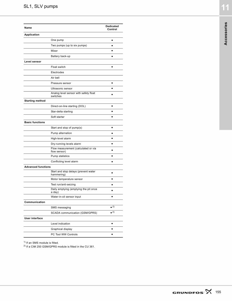
Ac
ce
ss
ori
es
SL1, SLV pumps 11
1) If an SMS module is fitted.2) If a CIM 250 GSM/GPRS module is fitted in the CU 361.
NameDedicated
Control
Application
One pump ●
Two pumps (up to six pumps) ●
Mixer ●
Battery back-up ●
Level sensor
Float switch ●
Electrodes
Air bell
Pressure sensor ●
Ultrasonic sensor ●Analog level sensor with safety float switches
●
Starting method
Direct-on-line starting (DOL) ●
Star-delta starting ●
Soft starter ●
Basic functions
Start and stop of pump(s) ●
Pump alternation ●
High-level alarm ●
Dry-running levels alarm ●Flow measurement (calculated or via flow sensor) ●
Pump statistics ●
Conflicting level alarm ●
Advanced functions
Start and stop delays (prevent water hammering)
●
Motor temperature sensor ●
Test run/anti-seizing ●Daily emptying (emptying the pit once a day)
●
Water-in-oil sensor input ●
Communication
SMS messaging ● 2)
SCADA communication (GSM/GPRS) ● 2)
User interface
Level indication ●
Graphical display ●
PC Tool WW Controls ●
155
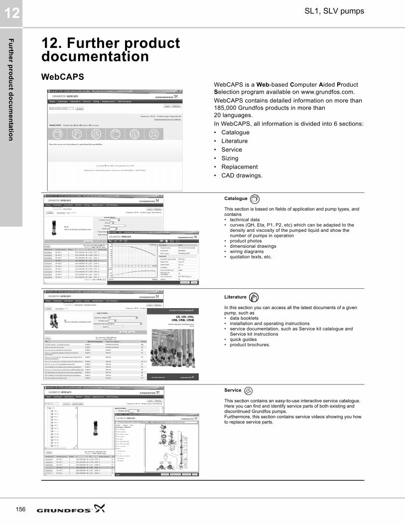
Fu
rthe
r pro
du
ct d
oc
um
en
tatio
n
SL1, SLV pumps12
156
12. Further product documentationWebCAPS
WebCAPS is a Web-based Computer Aided Product Selection program available on www.grundfos.com.
WebCAPS contains detailed information on more than 185,000 Grundfos products in more than 20 languages.
In WebCAPS, all information is divided into 6 sections:
• Catalogue
• Literature
• Service
• Sizing
• Replacement
• CAD drawings.
Catalogue
This section is based on fields of application and pump types, and contains • technical data• curves (QH, Eta, P1, P2, etc) which can be adapted to the
density and viscosity of the pumped liquid and show the number of pumps in operation
• product photos• dimensional drawings• wiring diagrams• quotation texts, etc.
Literature
In this section you can access all the latest documents of a given pump, such as• data booklets• installation and operating instructions• service documentation, such as Service kit catalogue and
Service kit instructions• quick guides• product brochures.
Service
This section contains an easy-to-use interactive service catalogue. Here you can find and identify service parts of both existing and discontinued Grundfos pumps.Furthermore, this section contains service videos showing you how to replace service parts.
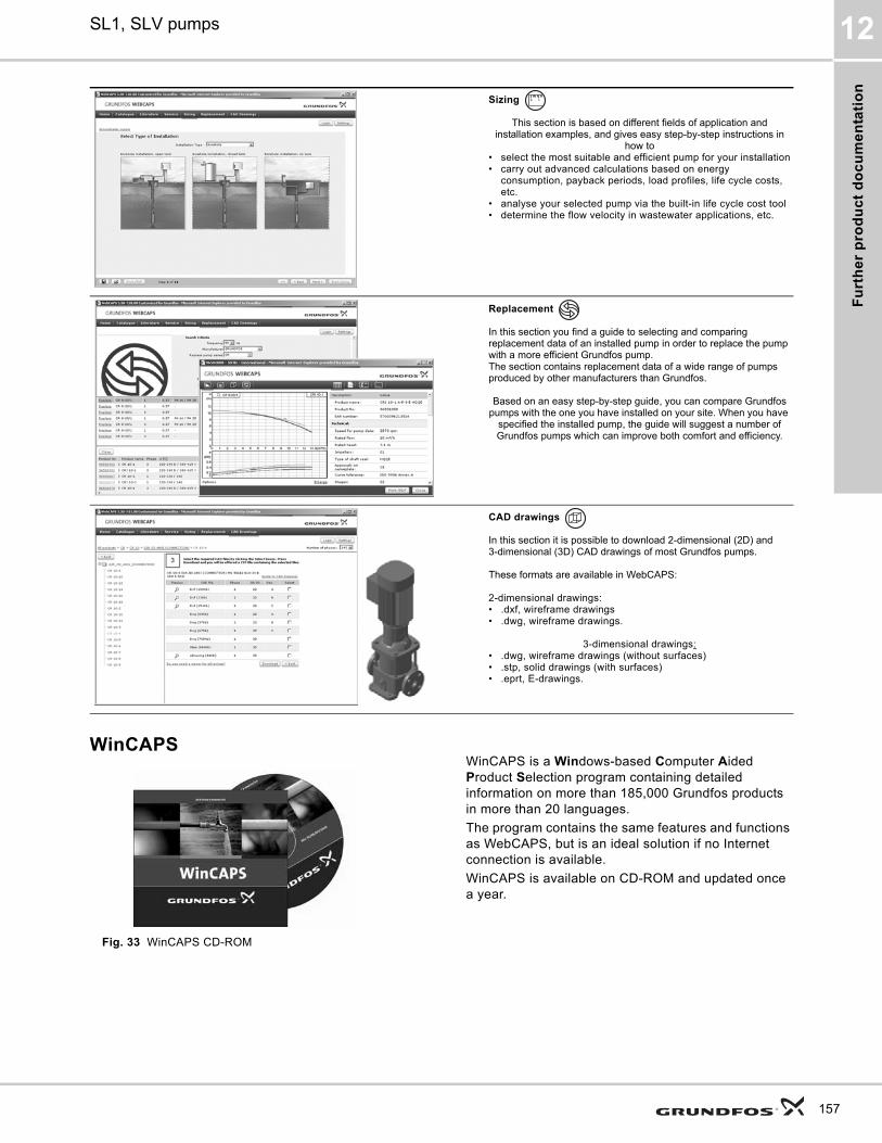
Fu
rth
er
pro
du
ct
do
cu
me
nta
tio
n
SL1, SLV pumps 12
WinCAPS
Fig. 33 WinCAPS CD-ROM
WinCAPS is a Windows-based Computer Aided Product Selection program containing detailed information on more than 185,000 Grundfos products in more than 20 languages.
The program contains the same features and functions as WebCAPS, but is an ideal solution if no Internet connection is available.
WinCAPS is available on CD-ROM and updated once a year.
Sizing
This section is based on different fields of application and installation examples, and gives easy step-by-step instructions in
how to• select the most suitable and efficient pump for your installation• carry out advanced calculations based on energy
consumption, payback periods, load profiles, life cycle costs, etc.
• analyse your selected pump via the built-in life cycle cost tool• determine the flow velocity in wastewater applications, etc.
Replacement
In this section you find a guide to selecting and comparing replacement data of an installed pump in order to replace the pump with a more efficient Grundfos pump. The section contains replacement data of a wide range of pumps produced by other manufacturers than Grundfos.
Based on an easy step-by-step guide, you can compare Grundfos pumps with the one you have installed on your site. When you have
specified the installed pump, the guide will suggest a number of Grundfos pumps which can improve both comfort and efficiency.
CAD drawings
In this section it is possible to download 2-dimensional (2D) and 3-dimensional (3D) CAD drawings of most Grundfos pumps.
These formats are available in WebCAPS:
2-dimensional drawings:• .dxf, wireframe drawings• .dwg, wireframe drawings.
3-dimensional drawings:• .dwg, wireframe drawings (without surfaces)• .stp, solid drawings (with surfaces)• .eprt, E-drawings.
0 1
157

158

159
GRUNDFOS Dosing, USA 2270 Northwest Parkway Suite 180 30067 Marietta, Georgia USA Phone: +1-770 956 7996 Telefax: +1-770 956 7836
GRUNDFOS Canada Inc. 2941 Brighton Road Oakville, Ontario L6H 6C9CanadaPhone: +1-905 829 9533 Telefax: +1-905 829 9512
Bombas GRUNDFOS de Mexico S.A. de C.V. Boulevard TLC No. 15Parque Industrial Stiva AeropuertoApodaca, N.L. Mexico 66600Phone: +52-81-8144 4000 Telefax: +52-81-8144 4010
The name Grundfos, the Grundfos logo, and the payoff Be–Think–Innovate are registrated trademarks owned by Grundfos Management A/S or Grundfos A/S, Denmark. All rights reserved worldwide.
Being responsible is our foundationThinking ahead makes it possible
Innovation is the essence
97656971 1011 USRepl. 97656971 0910
ECM: 1082185


![DP-, EF-, SL1-, SLV-, standard- og AUTOADAPT-pumpernet.grundfos.com/Appl/ccmsservices/public/... · A Tilsluttet en CI 100-kontrolboks [ ] Standardpumpe Pumpeudførelse Ex Eksplosionsbeskyttet](https://static.fdocuments.net/doc/165x107/6078e15040b57f411562f814/dp-ef-sl1-slv-standard-og-autoadapt-a-tilsluttet-en-ci-100-kontrolboks.jpg)


![Grundfos SLV.80.100.75.2.51D.C bomba : SLV.80.100.75.2 ......SLV.80.100.75.2.51D.C, 3*400 V, 50Hz P [kW] 0 2 4 6 8 NPSH [m] 0 5 10 15 20 P1 P2 751 104 286 466 DN100 DN80 180 18 8 380](https://static.fdocuments.net/doc/165x107/60c68b3b51e8137767287bd7/grundfos-slv8010075251dc-bomba-slv80100752-slv8010075251dc.jpg)