
SL-100 manual Product manual SL-100
39
© Geobrugg AG, Protection Systems, CH-8590 Romanshorn, Switzerland Subject to change without notice. TECCO ® SL-100 manual Proof of quality assurance/verification Installation manual System drawing / rope assembly drawing ISO 9001 Quality Certificate Proof of load carrying capacity of the system based on one-to-one field tests in cooperation with the WSL, Swiss Federal Institute for Forest, Snow and Landscape Research Edition: 01-N-FO / 12 Date: 16.11.2016 Product manual SL-100
Transcript of SL-100 manual Product manual SL-100
© Geobrugg AG, Protection Systems, CH-8590 Romanshorn, Switzerland
Subject to change without notice.
TECCO® SL-100 manual
Impact Pressure < 100 kN/m2
Proof of quality assurance/verification
Installation manual
System drawing / rope assembly drawing
ISO 9001 Quality Certificate
Proof of load carrying capacity of the system based on one-to-one field tests in cooperation with
the WSL, Swiss Federal Institute for Forest, Snow and Landscape Research
Edition: 01-N-FO / 12
Date: 16.11.2016
Product manual SL-100
Product manual SL-100
Page 2 / 39
© Geobrugg AG, Protection Systems, CH-8590 Romanshorn, Switzerland
Purpose and organization of the manual
This product manual ensures that Geobrugg shallow landslide protection systems are manufactured free
from defects in accordance with the latest technology and that the range of applications is clearly defined,
the functional efficiency is given, and the installation of the system is professionally carried out and con-
trolled.
The product manual is divided into the following sections
Proof of quality assurance / verification of conformity
Installation manual
System drawing / rope assembly drawing
ISO 9001 certificate
No claims are made that this document is complete. The manual describes standard applications and does
not take into account project specific parameters. Geobrugg cannot be held liable for any extra costs that
may be incurred for special cases. In case of uncertainties, please contact the manufacturer. The General
Sales Conditions of Geobrugg AG are applicable.
Responsible for the content of this manual:
GEOBRUGG AG
Aachstrasse 11
P.O. Box
CH-8590 Romanshorn/Switzerland
Tel. ++41-71-466 81 55
Fax. ++41-71-466 81 50
e-mail [email protected]
Romanshorn, November, 2016
(stamp / authorized signatures)

Product manual SL-100
Page 3 / 39
© Geobrugg AG, Protection Systems, CH-8590 Romanshorn, Switzerland
I Range of application
The design of shallow landslide protection systems is based on detailed investigations by specialized en-
gineering firms, particularly taking into account the following geotechnical aspects to define the range of
possible applications:
Former shallow landslide events
Condition of the slope (outcropping of springs, macro porosity, concave areas in the slope, bedrock
layer below ground layer, slope inclination)
Estimated rainfall intensity
Slide input parameter (volume, density, middle front velocity, height of failure, crack width)
Composition of debris flow (debris fraction, water content, density)
Probability of occurrence
Barrier location (consideration of local topography and localization of the structure to be protected)
Anchorage conditions
II Quality of the system components
Geobrugg AG, the former Geobrugg Protection Systems Division of Fatzer AG, Romanshorn has been
certified since August 22nd 1995 under the registration no. 34372 in accordance with the Quality Manage-
ment Systems Requirements (ISO 9001, 2000, revised 2007). The certifying body is the Swiss Association
for Quality and Management Systems (SQS), which belongs to EQ-Net 9000. The quality manual com-
pletely specifies how to test the system components (raw material, commercial and end products) compre-
hensively in order to exclude deficiencies in quality. The relevant certificates are attached as appendices.
III Functional efficiency of the barrier systems
The functional efficiency of the system is based on one-to-one field tests at the Veltheim test site (Canton
AG, Switzerland). The tested barrier could retain two surges with 60 m3 each and a maximum impact speed
of 11 m/s.
IV Quality control for installation
This product manual describes in detail the different steps for installation of the barriers. These steps must
be faithfully followed by local building contractors.
Product manual SL-100
Page 4 / 39
© Geobrugg AG, Protection Systems, CH-8590 Romanshorn, Switzerland
V Product liability
Rockfall, landslides, debris flows or avalanches are sporadic and unpredictable. Causes can be e.g. human
(construction, etc.) or environmental (weather, earthquakes, etc.). Due to the multiplicity of factors affecting
such events it is not and cannot be an exact science that guarantees the protection of individuals and
property.
However, by the application of sound engineering principles to a predictable range of parameters and by
the implementation of correctly designed protection measures in identified risk areas the exposure of injury
and loss of property can be reduced substantially.
Inspection and maintenance of such systems are an absolute requirement to ensure the desired protection
level. The system protection can also be impaired by events such as natural disasters, inadequate dimen-
sioning parameters or failure to use the prescribed standard components, systems and original parts;
and/or corrosion (caused by pollution of the environment or other man-made factors as well as other exter-
nal influences).
Geobrugg can assist with estimating the influence of larger deviations and special situations, and can offer
recommendations for feasible solutions. Geobrugg cannot, however, guarantee the same behaviour as in
the one-to-one landslide barrier tests. In critical cases, it is advisable to reinforce particular components as
compared with the standard barrier.
Product manual SL-100
Page 5 / 39
© Geobrugg AG, Protection Systems, CH-8590 Romanshorn, Switzerland
Contents
1 Introduction ......................................................................................................................................... 6 1.1 Validity of the installation instructions ................................................................................................... 6 1.2 Construction .......................................................................................................................................... 6 1.3 Anchor forces ...................................................................................................................................... 10
2 Installation of the barrier .................................................................................................................. 11
2.1 Installation steps of SL-100 barriers .................................................................................................... 11 2.2 Recommended installation tools ......................................................................................................... 13 2.3 Use of wire rope clips .......................................................................................................................... 14
3 Anchorages ........................................................................................................................................ 16
3.1 Marking of the anchor locations .......................................................................................................... 16 3.2 Rope anchors for retaining ropes ........................................................................................................ 17 3.3 Rope anchors for support ropes and lateral anchor ropes .................................................................. 18 3.4 Rope anchors for support rope separation .......................................................................................... 18 3.5 Change in direction upslope or going over a crest .............................................................................. 19 3.6 Downslope change in direction ........................................................................................................... 20 3.7 Anchorage of the post foundation ....................................................................................................... 21 3.8 Anchorage of the retaining ropes ........................................................................................................ 23 3.9 Anchorage of the lateral anchor ropes ................................................................................................ 24 3.10 Anchorage of the support ropes .......................................................................................................... 24 3.11 Anchorage of lateral and additional ropes........................................................................................... 24
4 Installation of the base plates, the posts and the ropes ............................................................... 25
4.1 Post sets .............................................................................................................................................. 25 4.2 Installation of the base plates .............................................................................................................. 27 4.3 Installation of the posts ........................................................................................................................ 29 4.4 Installation of lateral and intermediate anchor ropes .......................................................................... 32 4.5 Vertical ropes at border posts ............................................................................................................. 33 4.6 Top support rope ................................................................................................................................. 34 4.7 Support rope separation ...................................................................................................................... 35
5 Installation of the TECCO® mesh ..................................................................................................... 36 5.1 Hint for easier installation .................................................................................................................... 38
6 Final inspection ................................................................................................................................. 39
Product manual SL-100
Page 6 / 39
© Geobrugg AG, Protection Systems, CH-8590 Romanshorn, Switzerland
1 Introduction
1.1 Validity of the installation instructions
1.2 Construction
The shallow landslide barrier system consists of the following components:
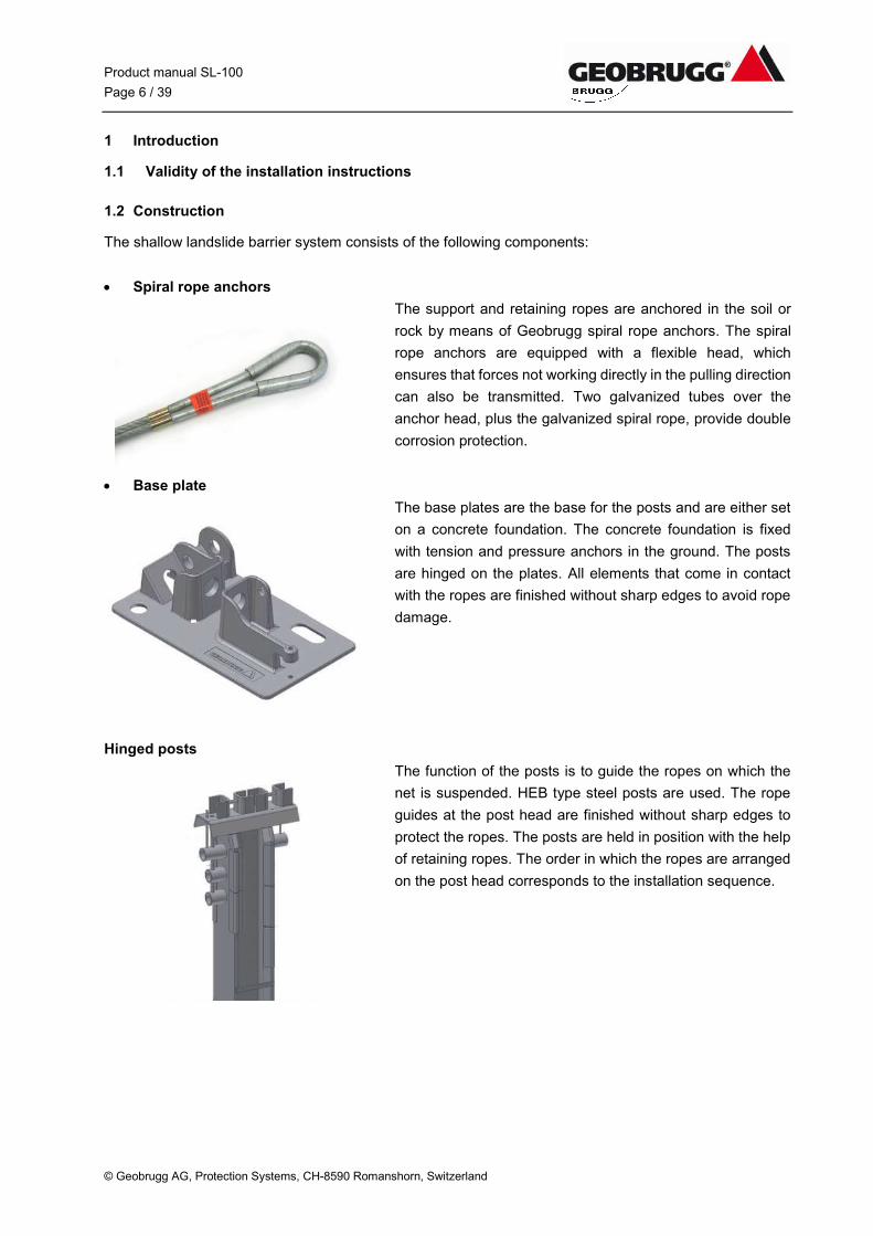
Spiral rope anchors
The support and retaining ropes are anchored in the soil or
rock by means of Geobrugg spiral rope anchors. The spiral
rope anchors are equipped with a flexible head, which
ensures that forces not working directly in the pulling direction
can also be transmitted. Two galvanized tubes over the
anchor head, plus the galvanized spiral rope, provide double
corrosion protection.
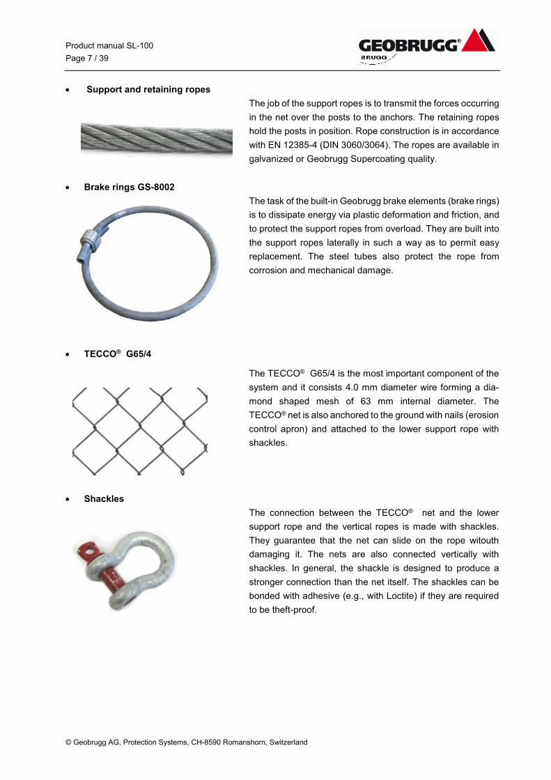
Base plate
The base plates are the base for the posts and are either set
on a concrete foundation. The concrete foundation is fixed
with tension and pressure anchors in the ground. The posts
are hinged on the plates. All elements that come in contact
with the ropes are finished without sharp edges to avoid rope
damage.
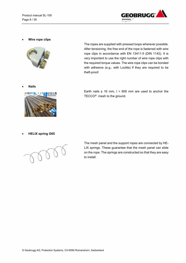
Hinged posts
The function of the posts is to guide the ropes on which the
net is suspended. HEB type steel posts are used. The rope
guides at the post head are finished without sharp edges to
protect the ropes. The posts are held in position with the help
of retaining ropes. The order in which the ropes are arranged
on the post head corresponds to the installation sequence.
Product manual SL-100
Page 7 / 39
© Geobrugg AG, Protection Systems, CH-8590 Romanshorn, Switzerland
Support and retaining ropes
The job of the support ropes is to transmit the forces occurring
in the net over the posts to the anchors. The retaining ropes
hold the posts in position. Rope construction is in accordance
with EN 12385-4 (DIN 3060/3064). The ropes are available in
galvanized or Geobrugg Supercoating quality.
Brake rings GS-8002
The task of the built-in Geobrugg brake elements (brake rings)
is to dissipate energy via plastic deformation and friction, and
to protect the support ropes from overload. They are built into
the support ropes laterally in such a way as to permit easy
replacement. The steel tubes also protect the rope from
corrosion and mechanical damage.
TECCO® G65/4
The TECCO® G65/4 is the most important component of the
system and it consists 4.0 mm diameter wire forming a dia-
mond shaped mesh of 63 mm internal diameter. The
TECCO® net is also anchored to the ground with nails (erosion
control apron) and attached to the lower support rope with
shackles.
Shackles
The connection between the TECCO® net and the lower
support rope and the vertical ropes is made with shackles.
They guarantee that the net can slide on the rope witouth
damaging it. The nets are also connected vertically with
shackles. In general, the shackle is designed to produce a
stronger connection than the net itself. The shackles can be
bonded with adhesive (e.g., with Loctite) if they are required
to be theft-proof.
Product manual SL-100
Page 8 / 39
© Geobrugg AG, Protection Systems, CH-8590 Romanshorn, Switzerland
Wire rope clips
The ropes are supplied with pressed loops wherever possible.
After tensioning, the free end of the rope is fastened with wire
rope clips in accordance with EN 13411-5 (DIN 1142). It is
very important to use the right number of wire rope clips with
the required torque values. The wire rope clips can be bonded
with adhesive (e.g., with Loctite) if they are required to be
theft-proof.
Nails
Earth nails 16 mm, l = 600 mm are used to anchor the
TECCO® mesh to the ground.
HELIX spring G65
The mesh panel and the support ropes are connected by HE-
LIX springs. These guarantee that the mesh panel can slide
on the rope. The springs are constructed so that they are easy
to install.
Product manual SL-100
Page 9 / 39
© Geobrugg AG, Protection Systems, CH-8590 Romanshorn, Switzerland
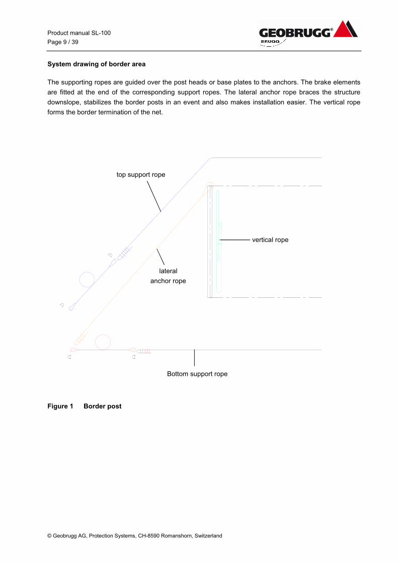
System drawing of border area
The supporting ropes are guided over the post heads or base plates to the anchors. The brake elements
are fitted at the end of the corresponding support ropes. The lateral anchor rope braces the structure
downslope, stabilizes the border posts in an event and also makes installation easier. The vertical rope
forms the border termination of the net.
Figure 1 Border post
top support rope
Bottom support rope
lateral
anchor rope
vertical rope
Product manual SL-100
Page 10 / 39
© Geobrugg AG, Protection Systems, CH-8590 Romanshorn, Switzerland
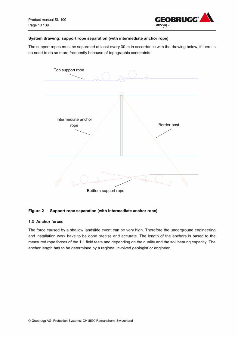
System drawing: support rope separation (with intermediate anchor rope)
The support ropes must be separated at least every 30 m in accordance with the drawing below, if there is
no need to do so more frequently because of topographic constraints.
Figure 2 Support rope separation (with intermediate anchor rope)
1.3 Anchor forces
The force caused by a shallow landslide event can be very high. Therefore the underground engineering
and installation work have to be done precise and accurate. The length of the anchors is based to the
measured rope forces of the 1:1 field tests and depending on the quality and the soil bearing capacity. The
anchor length has to be determined by a regional involved geologist or engineer.
Intermediate anchor
rope
Top support rope
Botttom support rope
Border post
Product manual SL-100
Page 11 / 39
© Geobrugg AG, Protection Systems, CH-8590 Romanshorn, Switzerland
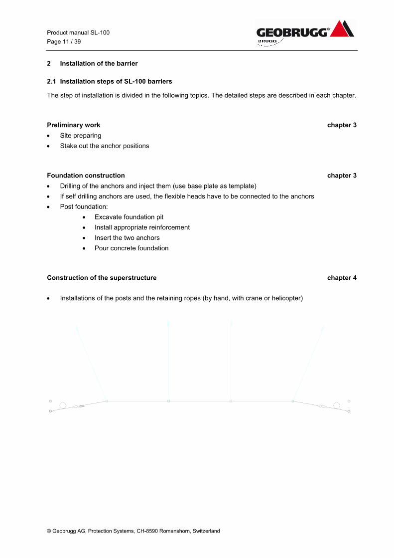
2 Installation of the barrier
2.1 Installation steps of SL-100 barriers
The step of installation is divided in the following topics. The detailed steps are described in each chapter.
Preliminary work chapter 3
Site preparing
Stake out the anchor positions
Foundation construction chapter 3
Drilling of the anchors and inject them (use base plate as template)
If self drilling anchors are used, the flexible heads have to be connected to the anchors
Post foundation:
Excavate foundation pit
Install appropriate reinforcement
Insert the two anchors
Pour concrete foundation
Construction of the superstructure chapter 4
Installations of the posts and the retaining ropes (by hand, with crane or helicopter)
Product manual SL-100
Page 12 / 39
© Geobrugg AG, Protection Systems, CH-8590 Romanshorn, Switzerland
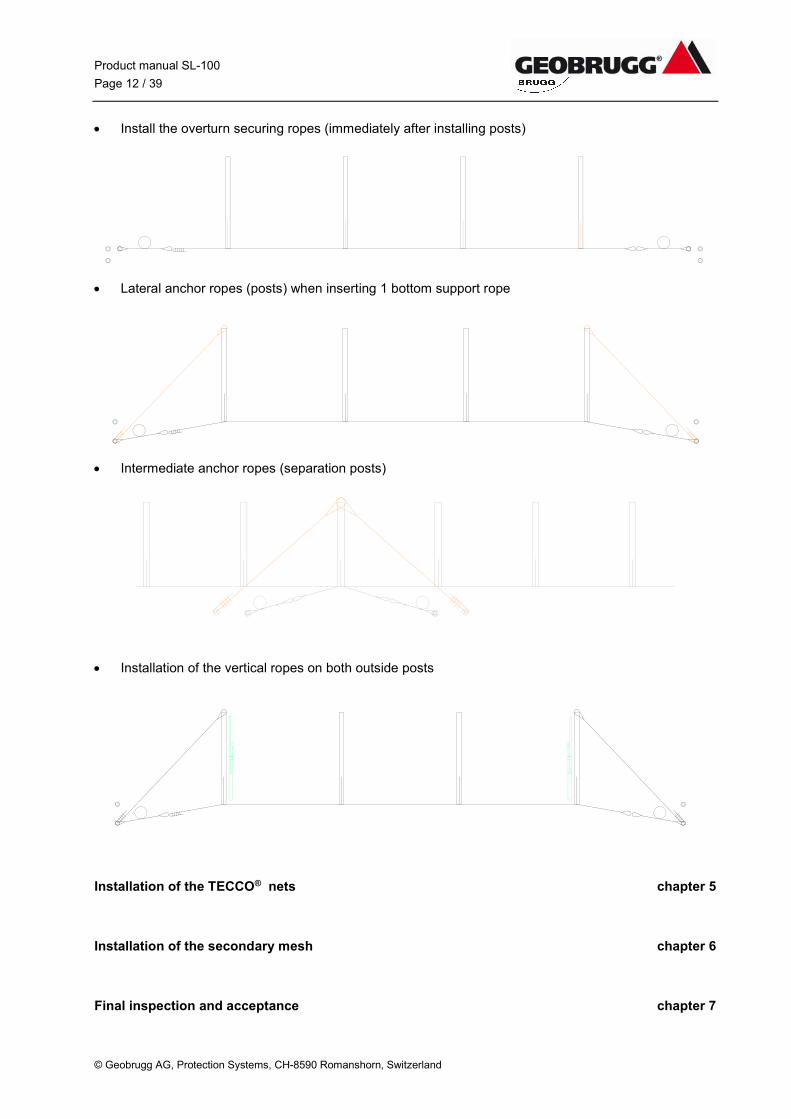
Install the overturn securing ropes (immediately after installing posts)
Lateral anchor ropes (posts) when inserting 1 bottom support rope
Intermediate anchor ropes (separation posts)
Installation of the vertical ropes on both outside posts
Installation of the TECCO® nets chapter 5
Installation of the secondary mesh chapter 6
Final inspection and acceptance chapter 7
Product manual SL-100
Page 13 / 39
© Geobrugg AG, Protection Systems, CH-8590 Romanshorn, Switzerland
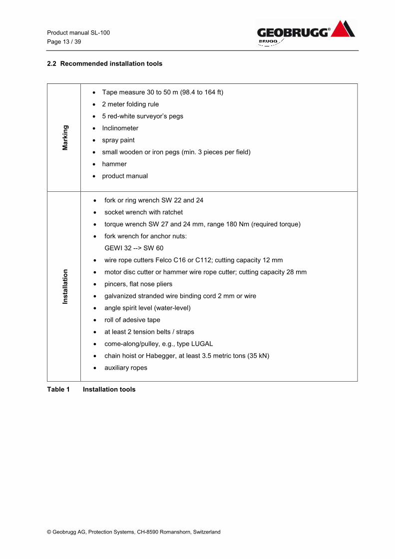
2.2 Recommended installation tools
Mark
ing
Tape measure 30 to 50 m (98.4 to 164 ft)
2 meter folding rule
5 red-white surveyor’s pegs
Inclinometer
spray paint
small wooden or iron pegs (min. 3 pieces per field)
hammer
product manual
Insta
llati
on
fork or ring wrench SW 22 and 24
socket wrench with ratchet
torque wrench SW 27 and 24 mm, range 180 Nm (required torque)
fork wrench for anchor nuts:
GEWI 32 --> SW 60
wire rope cutters Felco C16 or C112; cutting capacity 12 mm
motor disc cutter or hammer wire rope cutter; cutting capacity 28 mm
pincers, flat nose pliers
galvanized stranded wire binding cord 2 mm or wire
angle spirit level (water-level)
roll of adesive tape
at least 2 tension belts / straps
come-along/pulley, e.g., type LUGAL
chain hoist or Habegger, at least 3.5 metric tons (35 kN)
auxiliary ropes
Table 1 Installation tools
Product manual SL-100
Page 14 / 39
© Geobrugg AG, Protection Systems, CH-8590 Romanshorn, Switzerland
min. 3 x e h e t
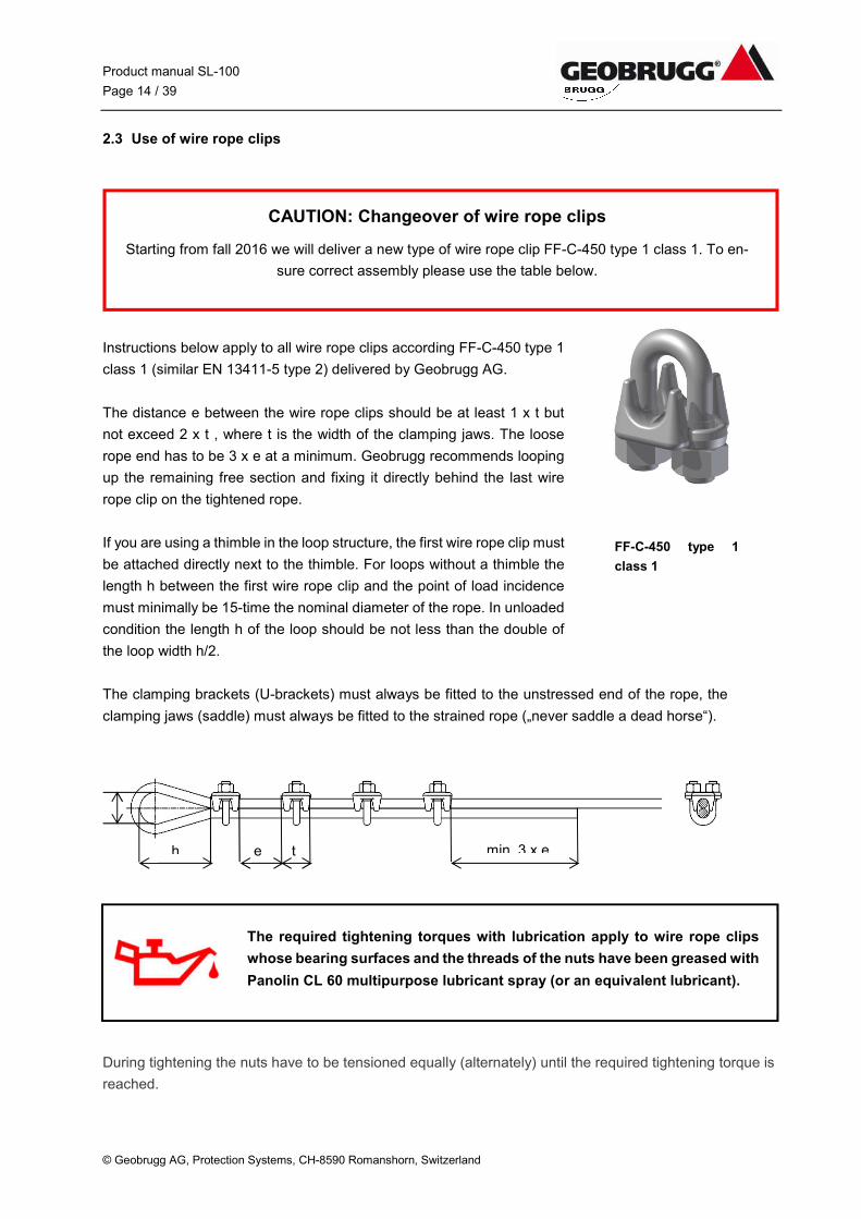
2.3 Use of wire rope clips
Instructions below apply to all wire rope clips according FF-C-450 type 1
class 1 (similar EN 13411-5 type 2) delivered by Geobrugg AG.
The distance e between the wire rope clips should be at least 1 x t but
not exceed 2 x t , where t is the width of the clamping jaws. The loose
rope end has to be 3 x e at a minimum. Geobrugg recommends looping
up the remaining free section and fixing it directly behind the last wire
rope clip on the tightened rope.
If you are using a thimble in the loop structure, the first wire rope clip must
be attached directly next to the thimble. For loops without a thimble the
length h between the first wire rope clip and the point of load incidence
must minimally be 15-time the nominal diameter of the rope. In unloaded
condition the length h of the loop should be not less than the double of
the loop width h/2.
The clamping brackets (U-brackets) must always be fitted to the unstressed end of the rope, the
clamping jaws (saddle) must always be fitted to the strained rope („never saddle a dead horse“).
During tightening the nuts have to be tensioned equally (alternately) until the required tightening torque is
reached.
The required tightening torques with lubrication apply to wire rope clips
whose bearing surfaces and the threads of the nuts have been greased with
Panolin CL 60 multipurpose lubricant spray (or an equivalent lubricant).
FF-C-450 type 1
class 1
CAUTION: Changeover of wire rope clips
Starting from fall 2016 we will deliver a new type of wire rope clip FF-C-450 type 1 class 1. To en-
sure correct assembly please use the table below.
Product manual SL-100
Page 15 / 39
© Geobrugg AG, Protection Systems, CH-8590 Romanshorn, Switzerland
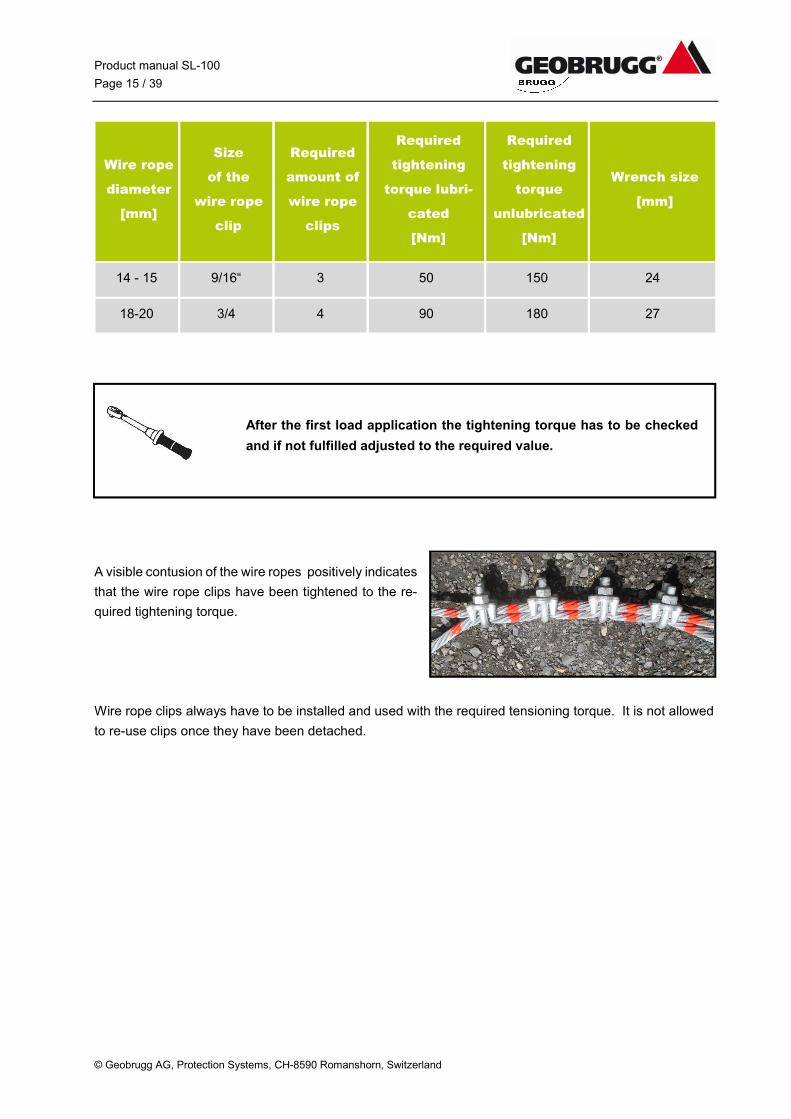
Wire rope
diameter
[mm]
Size
of the
wire rope
clip
Required
amount of
wire rope
clips
Required
tightening
torque lubri-
cated
[Nm]
Required
tightening
torque
unlubricated
[Nm]
Wrench size
[mm]
14 - 15 9/16“ 3 50 150 24
18-20 3/4 4 90 180 27
A visible contusion of the wire ropes positively indicates
that the wire rope clips have been tightened to the re-
quired tightening torque.
Wire rope clips always have to be installed and used with the required tensioning torque. It is not allowed
to re-use clips once they have been detached.
After the first load application the tightening torque has to be checked
and if not fulfilled adjusted to the required value.
Product manual SL-100
Page 16 / 39
© Geobrugg AG, Protection Systems, CH-8590 Romanshorn, Switzerland
3 Anchorages
3.1 Marking of the anchor locations
The line followed by the barrier should be planned so as to be as straight and horizontal as possible. Larger
irregularities in the terrain must be bypassed or evened out as needed (fill up holes, flatten bumps or mark
off along the contour line).
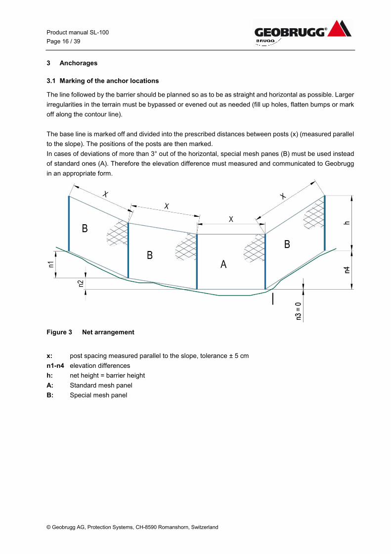
The base line is marked off and divided into the prescribed distances between posts (x) (measured parallel
to the slope). The positions of the posts are then marked.
In cases of deviations of more than 3° out of the horizontal, special mesh panes (B) must be used instead
of standard ones (A). Therefore the elevation difference must measured and communicated to Geobrugg
in an appropriate form.
Figure 3 Net arrangement
x: post spacing measured parallel to the slope, tolerance ± 5 cm
n1-n4 elevation differences
h: net height = barrier height
A: Standard mesh panel
B: Special mesh panel
Product manual SL-100
Page 17 / 39
©Geobrugg AG, Protection Systems, CH-8590 Romanshorn, Switzerland
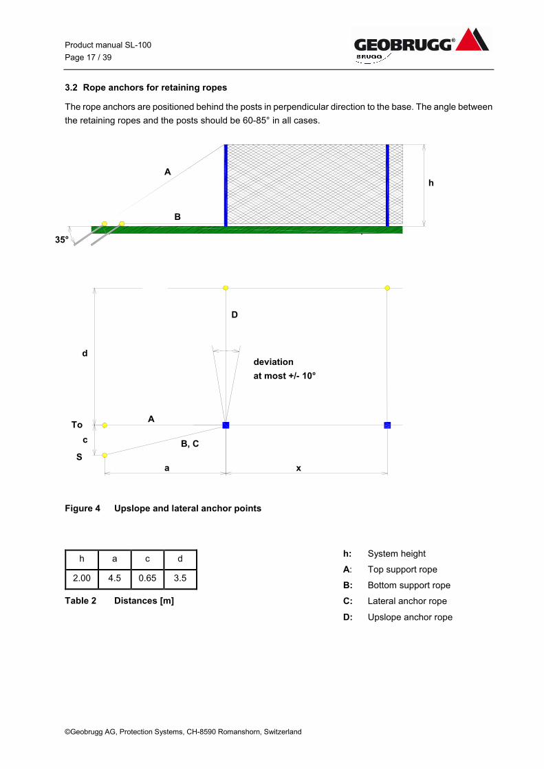
3.2 Rope anchors for retaining ropes
The rope anchors are positioned behind the posts in perpendicular direction to the base. The angle between
the retaining ropes and the posts should be 60-85° in all cases.
Figure 4 Upslope and lateral anchor points
h a c d
2.00 4.5 0.65 3.5
Table 2 Distances [m]
h: System height
A: Top support rope
B: Bottom support rope
C: Lateral anchor rope
D: Upslope anchor rope
deviation
at most +/- 10°
D
d
c
a x
A
B, C
To
S
A
B
35°
h
Product manual SL-100
Page 18 / 39
©Geobrugg AG, Protection Systems, CH-8590 Romanshorn, Switzerland
3.3 Rope anchors for support ropes and lateral anchor ropes
One bottom support rope is used. Both the bottom support rope and lateral anchor rope require the same
anchor, which is located at a and c distance away from the nearest base plate (S position), the anchors for
the top support rope are in line with the barrier and are located at a distance a away from the last base
plate. (To position).
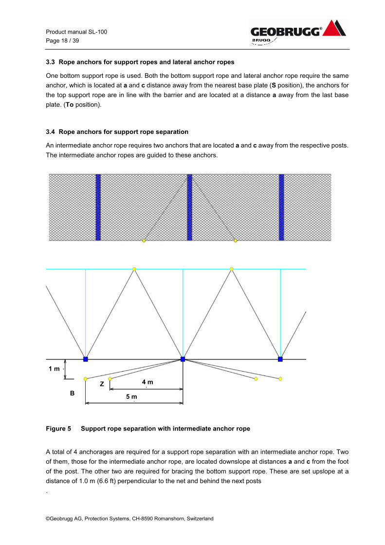
3.4 Rope anchors for support rope separation
An intermediate anchor rope requires two anchors that are located a and c away from the respective posts.
The intermediate anchor ropes are guided to these anchors.
Figure 5 Support rope separation with intermediate anchor rope
A total of 4 anchorages are required for a support rope separation with an intermediate anchor rope. Two
of them, those for the intermediate anchor rope, are located downslope at distances a and c from the foot
of the post. The other two are required for bracing the bottom support rope. These are set upslope at a
distance of 1.0 m (6.6 ft) perpendicular to the net and behind the next posts
.
1 m
4 m
5 m B
Z
Product manual SL-100
Page 19 / 39
©Geobrugg AG, Protection Systems, CH-8590 Romanshorn, Switzerland
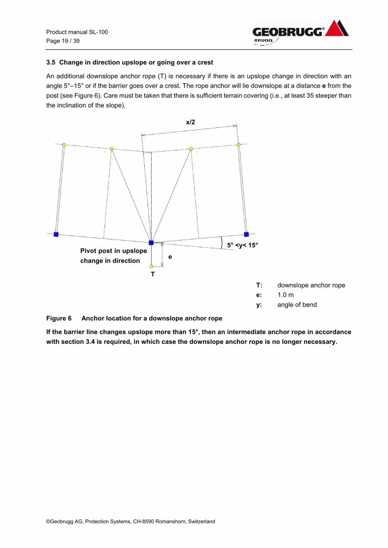
3.5 Change in direction upslope or going over a crest
An additional downslope anchor rope (T) is necessary if there is an upslope change in direction with an
angle 5°–15° or if the barrier goes over a crest. The rope anchor will lie downslope at a distance e from the
post (see Figure 6). Care must be taken that there is sufficient terrain covering (i.e., at least 35 steeper than
the inclination of the slope).
T: downslope anchor rope
e: 1.0 m
y: angle of bend
Figure 6 Anchor location for a downslope anchor rope
If the barrier line changes upslope more than 15°, then an intermediate anchor rope in accordance
with section 3.4 is required, in which case the downslope anchor rope is no longer necessary.
5° <y< 15°
e
T
Pivot post in upslope
change in direction
x/2
Product manual SL-100
Page 20 / 39
©Geobrugg AG, Protection Systems, CH-8590 Romanshorn, Switzerland
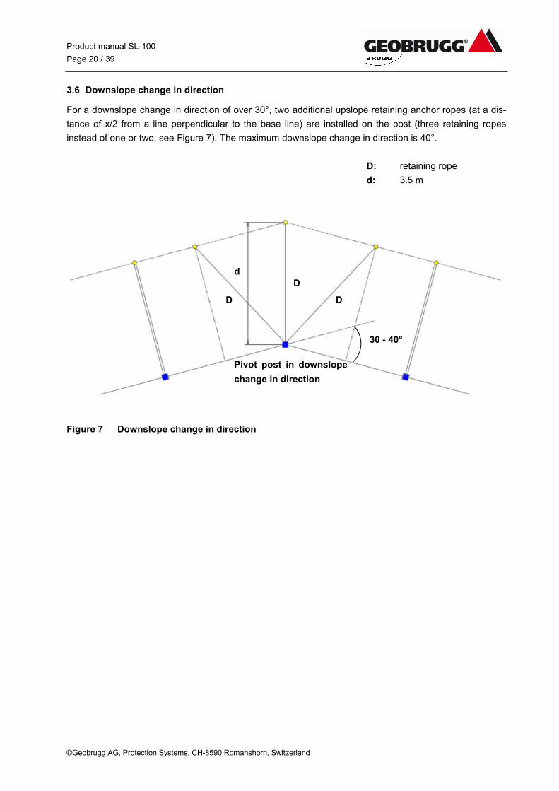
3.6 Downslope change in direction
For a downslope change in direction of over 30°, two additional upslope retaining anchor ropes (at a dis-
tance of x/2 from a line perpendicular to the base line) are installed on the post (three retaining ropes
instead of one or two, see Figure 7). The maximum downslope change in direction is 40°.
D: retaining rope
d: 3.5 m
Figure 7 Downslope change in direction
30 - 40°
Pivot post in downslope
change in direction
d
D D
D
Product manual SL-100
Page 21 / 39
©Geobrugg AG, Protection Systems, CH-8590 Romanshorn, Switzerland
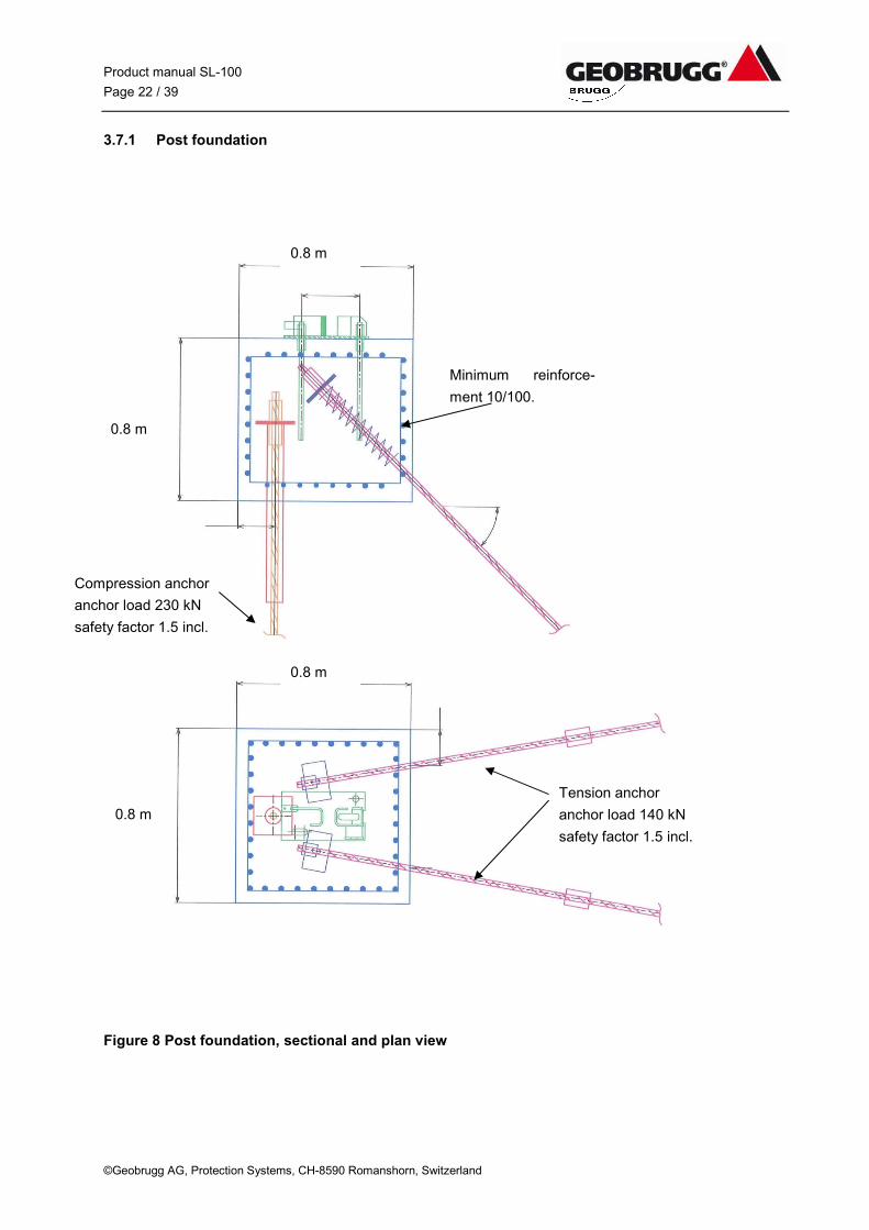
3.7 Anchorage of the post foundation
The reinforced post foundation transfers the horizontal and vertical load from the foundation over the an-
chorage to the ground. The post foundation is anchored with one compression anchor and two tension
anchors. The compression anchor has to be drilled in vertical direction and the two tension anchors have
to be built in 45° to horizontal direction and 10° inclined to the earth flow direction.
To have the optimum load transfer it is necessary to put quadratic steel plates at the end of the anchors
and to fix them with a nut. The connection between the foundation and the base plate is done with two
shorter bars built in vertical direction. The base plate has to be installed to these bars having the elongated
holes valley site.
Installation steps:
Dig out the foundation hole
Drill the anchorage. Place tension anchor with 45° to the ground plate line
Shutter the foundation and build in the reinforcement. Put on top the anchor plates.
Build in the two bars for the base plate (Use the base plate as a face mould).
Concrete the foundation. Please round the foundation edges because support rope is led along the
foundation.
The fastening of nuts may not be tightened until the concrete has cured completely.
Product manual SL-100
Page 22 / 39
©Geobrugg AG, Protection Systems, CH-8590 Romanshorn, Switzerland
3.7.1 Post foundation
Figure 8 Post foundation, sectional and plan view
Tension anchor
anchor load 140 kN
safety factor 1.5 incl.
Compression anchor
anchor load 230 kN
safety factor 1.5 incl.
Minimum reinforce-
ment 10/100.
0.8 m
0.8 m
0.8 m
0.8 m
Product manual SL-100
Page 23 / 39
©Geobrugg AG, Protection Systems, CH-8590 Romanshorn, Switzerland
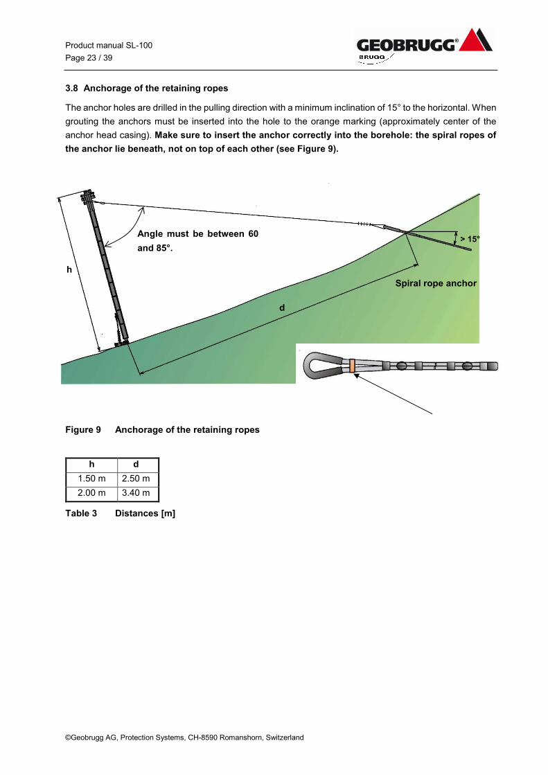
3.8 Anchorage of the retaining ropes
The anchor holes are drilled in the pulling direction with a minimum inclination of 15° to the horizontal. When
grouting the anchors must be inserted into the hole to the orange marking (approximately center of the
anchor head casing). Make sure to insert the anchor correctly into the borehole: the spiral ropes of
the anchor lie beneath, not on top of each other (see Figure 9).
Figure 9 Anchorage of the retaining ropes
h d
1.50 m 2.50 m
2.00 m 3.40 m
Table 3 Distances [m]
Spiral rope anchor
h
d
Angle must be between 60
and 85°. > 15°
Product manual SL-100
Page 24 / 39
©Geobrugg AG, Protection Systems, CH-8590 Romanshorn, Switzerland
3.9 Anchorage of the lateral anchor ropes
The anchor S (see Figure 4) for the lateral anchor rope should be installed as nearly as possible in the
pulling direction of the lateral anchor rope.
3.10 Anchorage of the support ropes
The bottom support rope is fastened to anchor S, which should be installed as flat as possible (but at least
35° to the surface of the ground). The top support rope is fastened to anchor To in the line of the barrier in
a distance of 4.5 m (14.8 ft).
3.11 Anchorage of lateral and additional ropes
If there is a change in direction upslope or over a crest, an additional downslope lateral anchor rope (T) is
necessary. Here the drill hole for the anchor should be placed as nearly as possible in the pulling direction
of the anchor rope. Care must be taken that the terrain affords enough covering (i.e., at least 35° steeper
than the slope inclination).
If this change in direction is greater than 15°, intermediate anchor ropes (Z) are installed instead of the
downslope anchor rope (T), (in this case, it is again important that the terrain afford enough covering, i.e.,
at least 35° steeper than the surface of the ground).
Product manual SL-100
Page 25 / 39
©Geobrugg AG, Protection Systems, CH-8590 Romanshorn, Switzerland
4 Installation of the base plates, the posts and the ropes
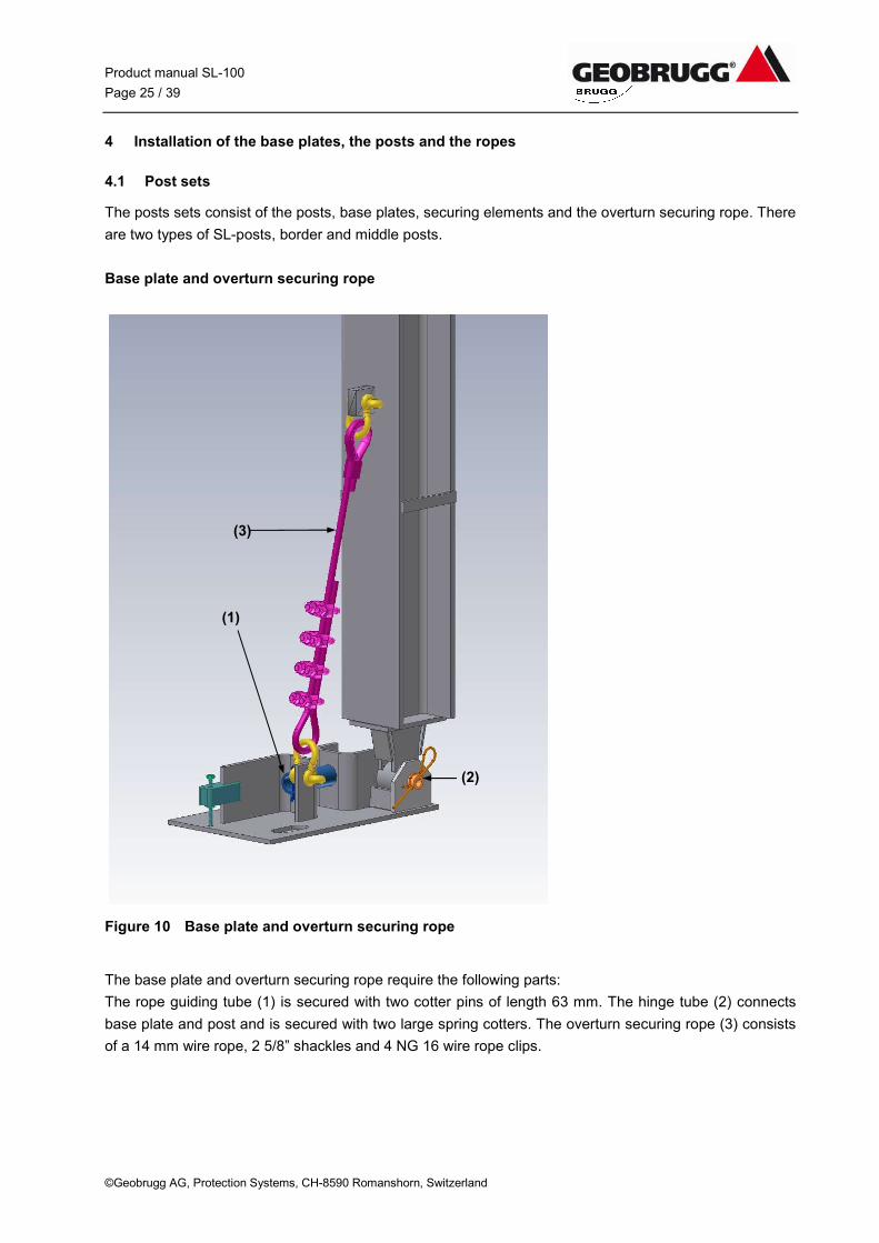
4.1 Post sets
The posts sets consist of the posts, base plates, securing elements and the overturn securing rope. There
are two types of SL-posts, border and middle posts.
Base plate and overturn securing rope
Figure 10 Base plate and overturn securing rope
The base plate and overturn securing rope require the following parts:
The rope guiding tube (1) is secured with two cotter pins of length 63 mm. The hinge tube (2) connects
base plate and post and is secured with two large spring cotters. The overturn securing rope (3) consists
of a 14 mm wire rope, 2 5/8” shackles and 4 NG 16 wire rope clips.
(1)
(3)
(2)
Product manual SL-100
Page 26 / 39
©Geobrugg AG, Protection Systems, CH-8590 Romanshorn, Switzerland
Posts
Post height
The posts are ca. 500 mm higher than the defined useful height of the system, in order to guarantee that
the useful height is also achieved in the center of the field. This factor must be considered if clearance is
restricted above the barrier.
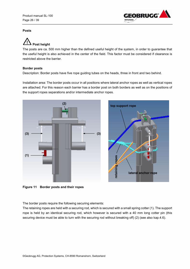
Border posts
Description: Border posts have five rope guiding tubes on the heads, three in front and two behind.
Installation area: The border posts occur in all positions where lateral anchor ropes as well as vertical ropes
are attached. For this reason each barrier has a border post on both borders as well as on the positions of
the support ropes separations and/or intermediate anchor ropes.
Figure 11 Border posts and their ropes
The border posts require the following securing elements:
The retaining ropes are held with a securing rod, which is secured with a small spring cotter (1). The support
rope is held by an identical securing rod, which however is secured with a 40 mm long cotter pin (this
securing device must be able to turn with the securing rod without breaking off) (2) (see also kap.4.6).
(2)
(3)
(1)
(3)
top support rope
lateral anchor rope
reta
inin
g r
op
es
Product manual SL-100
Page 27 / 39
©Geobrugg AG, Protection Systems, CH-8590 Romanshorn, Switzerland
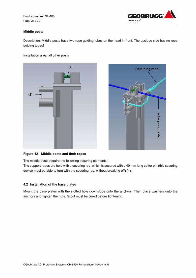
Middle posts
Description: Middle posts have two rope guiding tubes on the head in front. The upslope side has no rope
guiding tubes!
Installation area: all other posts
Figure 12 Middle posts and their ropes
The middle posts require the following securing elements:
The support ropes are held with a securing rod, which is secured with a 40 mm long cotter pin (this securing
device must be able to turn with the securing rod, without breaking off) (1).
4.2 Installation of the base plates
Mount the base plates with the slotted hole downslope onto the anchors. Then place washers onto the
anchors and tighten the nuts. Grout must be cured before tightening.
(1)
(2)
Retaining rope
top
su
pp
ort
ro
pe
Product manual SL-100
Page 28 / 39
©Geobrugg AG, Protection Systems, CH-8590 Romanshorn, Switzerland
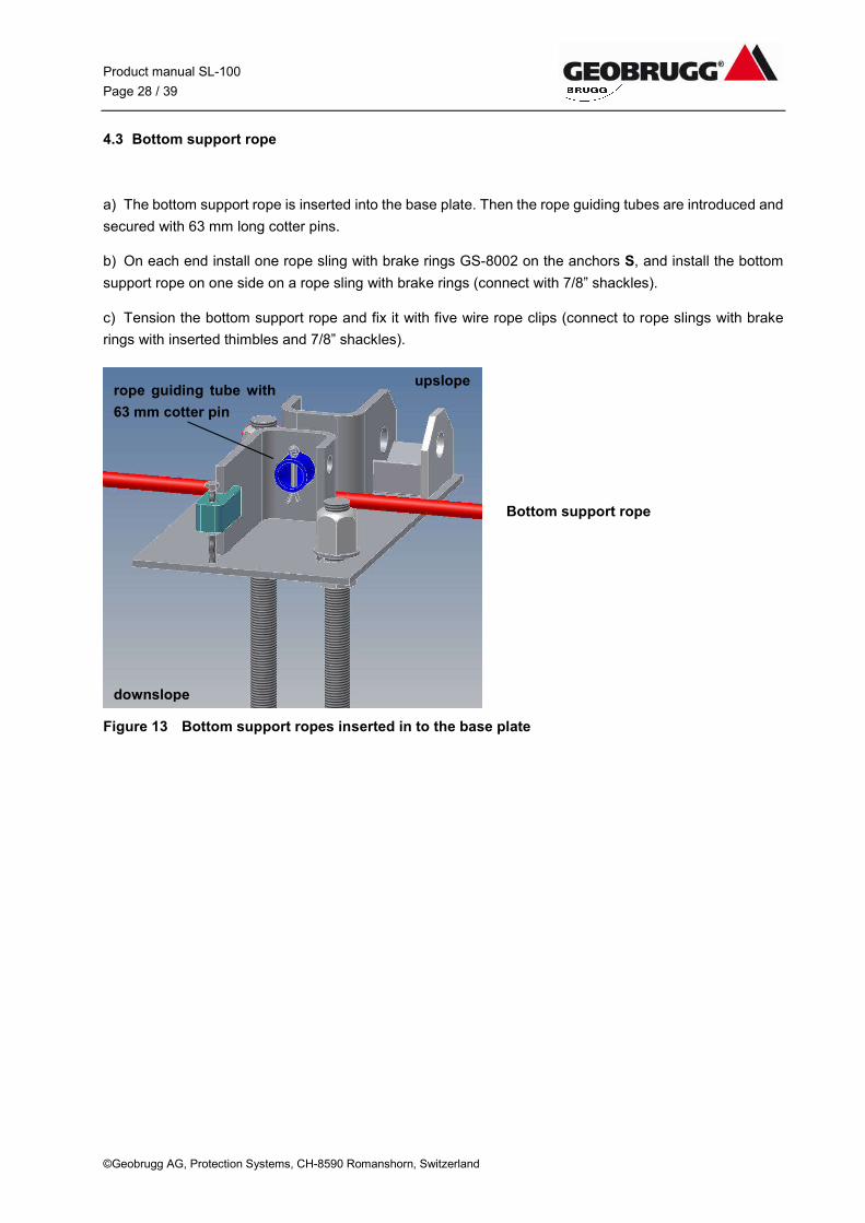
4.3 Bottom support rope
a) The bottom support rope is inserted into the base plate. Then the rope guiding tubes are introduced and
secured with 63 mm long cotter pins.
b) On each end install one rope sling with brake rings GS-8002 on the anchors S, and install the bottom
support rope on one side on a rope sling with brake rings (connect with 7/8” shackles).
c) Tension the bottom support rope and fix it with five wire rope clips (connect to rope slings with brake
rings with inserted thimbles and 7/8” shackles).
Figure 13 Bottom support ropes inserted in to the base plate
Bottom support rope
downslope
upslope rope guiding tube with
63 mm cotter pin
Product manual SL-100
Page 29 / 39
©Geobrugg AG, Protection Systems, CH-8590 Romanshorn, Switzerland
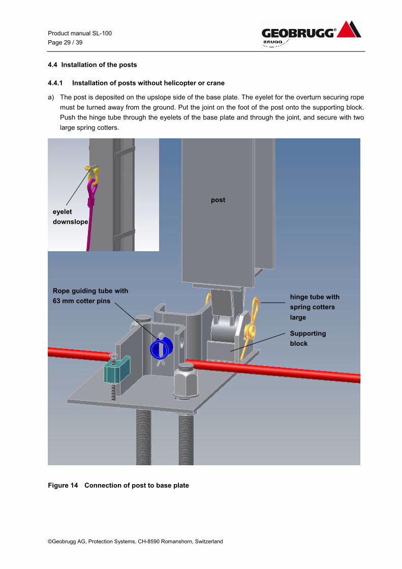
4.4 Installation of the posts
4.4.1 Installation of posts without helicopter or crane
a) The post is deposited on the upslope side of the base plate. The eyelet for the overturn securing rope
must be turned away from the ground. Put the joint on the foot of the post onto the supporting block.
Push the hinge tube through the eyelets of the base plate and through the joint, and secure with two
large spring cotters.
Figure 14 Connection of post to base plate
post
Rope guiding tube with
63 mm cotter pins hinge tube with
spring cotters
large
Supporting
block
eyelet
downslope
Product manual SL-100
Page 30 / 39
©Geobrugg AG, Protection Systems, CH-8590 Romanshorn, Switzerland
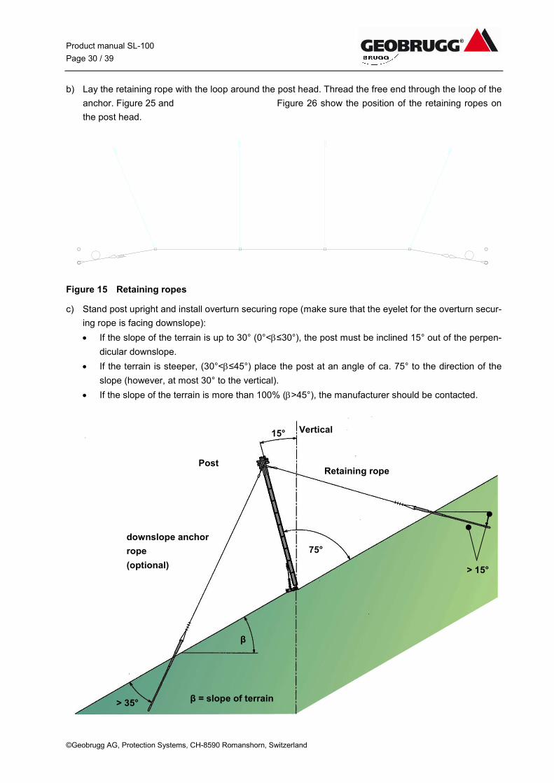
b) Lay the retaining rope with the loop around the post head. Thread the free end through the loop of the
anchor. Figure 25 and Figure 26 show the position of the retaining ropes on
the post head.
Figure 15 Retaining ropes
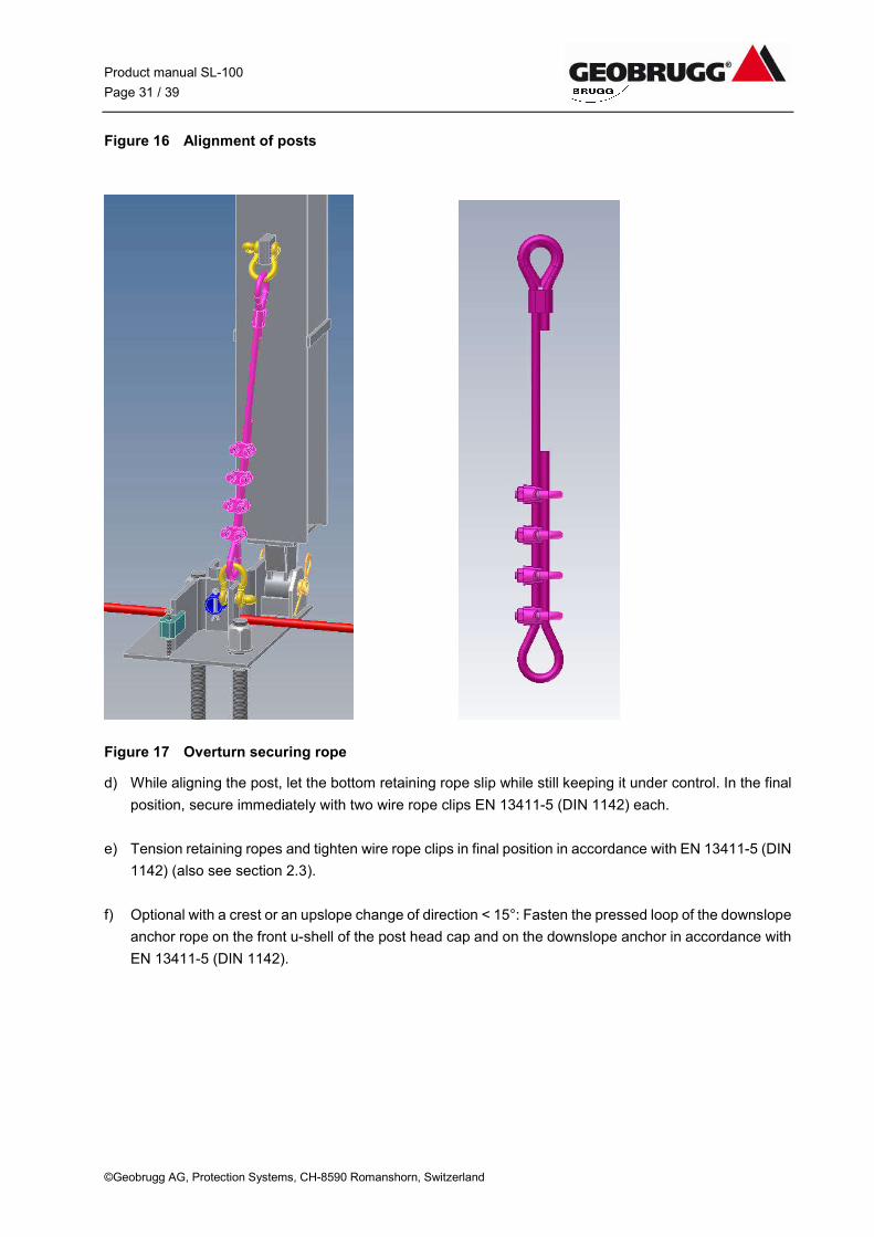
c) Stand post upright and install overturn securing rope (make sure that the eyelet for the overturn secur-
ing rope is facing downslope):
If the slope of the terrain is up to 30° (0°<≤30°), the post must be inclined 15° out of the perpen-
dicular downslope.
If the terrain is steeper, (30°<≤45°) place the post at an angle of ca. 75° to the direction of the
slope (however, at most 30° to the vertical).
If the slope of the terrain is more than 100% (>45°), the manufacturer should be contacted.
Vertical
Post
downslope anchor
rope
(optional)
β = slope of terrain
Retaining rope
75°
β
> 35°
> 15°
15°
Product manual SL-100
Page 31 / 39
©Geobrugg AG, Protection Systems, CH-8590 Romanshorn, Switzerland
Figure 16 Alignment of posts
Figure 17 Overturn securing rope
d) While aligning the post, let the bottom retaining rope slip while still keeping it under control. In the final
position, secure immediately with two wire rope clips EN 13411-5 (DIN 1142) each.
e) Tension retaining ropes and tighten wire rope clips in final position in accordance with EN 13411-5 (DIN
1142) (also see section 2.3).
f) Optional with a crest or an upslope change of direction < 15°: Fasten the pressed loop of the downslope
anchor rope on the front u-shell of the post head cap and on the downslope anchor in accordance with
EN 13411-5 (DIN 1142).
Product manual SL-100
Page 32 / 39
©Geobrugg AG, Protection Systems, CH-8590 Romanshorn, Switzerland
4.4.2 Installation of posts with helicopter or crane
Caution for installation using a helicopter:
The rungs that are welded laterally into the post profile are only there to facilitate climbing. They may not
be used as “towing hooks” for purposes of transportation.
a) Before flying, hang the upslope retaining rope with the pressed loop on the post head and secure with
the securing rod.
b) Fly the post or hoist with crane
c) While lowering the post, set the joint on the supporting block, insert the hinge tube and secure with
large spring cotter.
d) Tilt the post downslope before realising it, temporarily fasten the retaining rope to the upslope rope
anchor with two wire rope clips EN 13411-5 (DIN 1142), and install the overturn securing rope.
e) Align the post as described in the previous section.
f) Fasten the retaining rope to the rope anchor with 4 wire rope clips EN 13411-5 (DIN 1142).
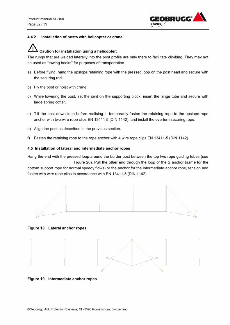
4.5 Installation of lateral and intermediate anchor ropes
Hang the end with the pressed loop around the border post between the top two rope guiding tubes (see
Figure 26). Pull the other end through the loop of the S anchor (same for the
bottom support rope for normal speedy flows) or the anchor for the intermediate anchor rope, tension and
fasten with wire rope clips in accordance with EN 13411-5 (DIN 1142).
Figure 18 Lateral anchor ropes
Figure 19 Intermediate anchor ropes
Product manual SL-100
Page 33 / 39
©Geobrugg AG, Protection Systems, CH-8590 Romanshorn, Switzerland
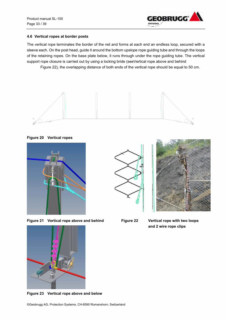
4.6 Vertical ropes at border posts
The vertical rope terminates the border of the net and forms at each end an endless loop, secured with a
sleeve each. On the post head, guide it around the bottom upslope rope guiding tube and through the loops
of the retaining ropes. On the base plate below, it runs through under the rope guiding tube. The vertical
support rope closure is carried out by using a locking bride (seeVertical rope above and behind
Figure 22), the overlapping distance of both ends of the vertical rope should be equal to 50 cm.
Figure 20 Vertical ropes
Figure 21 Vertical rope above and behind Figure 22 Vertical rope with two loops
and 2 wire rope clips
Figure 23 Vertical rope above and below
Product manual SL-100
Page 34 / 39
© Geobrugg AG, Geobrugg Protection Systems, CH-8590 Romanshorn, Switzerland
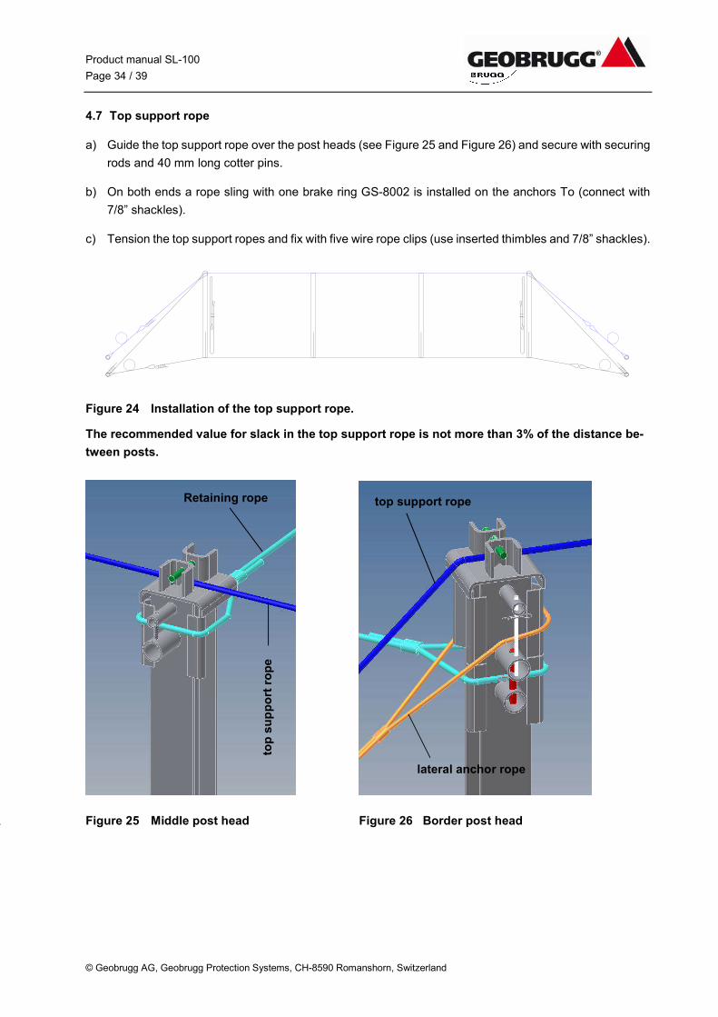
4.7 Top support rope
a) Guide the top support rope over the post heads (see Figure 25 and Figure 26) and secure with securing
rods and 40 mm long cotter pins.
b) On both ends a rope sling with one brake ring GS-8002 is installed on the anchors To (connect with
7/8” shackles).
c) Tension the top support ropes and fix with five wire rope clips (use inserted thimbles and 7/8” shackles).
Figure 24 Installation of the top support rope.
The recommended value for slack in the top support rope is not more than 3% of the distance be-
tween posts.
Figure 25 Middle post head Figure 26 Border post head
retaining rope.
top support rope
lateral anchor rope
Retaining rope
top
su
pp
ort
ro
pe

Product manual SL-100
Page 35 / 39
© Geobrugg AG, Geobrugg Protection Systems, CH-8590 Romanshorn, Switzerland
4.8 Support rope separation
With a support rope separation, a border type post must be installed. The top support ropes are guided
onto rope slings with brake rings that has a loop with thimble on one side and on the other side a loop with
a length of 700 mm. Lay this around the post head (border type post) as shown in Figure 27. The TECCO®
net is fixed with HELIX® springs onto rope sling.
Figure 27 Support rope separation
Figure 28 Tension belts between the posts for installing the nets
Border type post
Product manual SL-100
Page 36 / 39
© Geobrugg AG, Geobrugg Protection Systems, CH-8590 Romanshorn, Switzerland
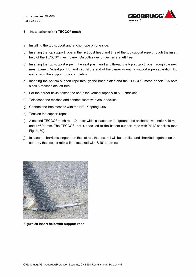
5 Installation of the TECCO® mesh
a) Installing the top support and anchor rope on one side.
b) Inserting the top support rope in the first post head and thread the top support rope through the insert
help of the TECCO® mesh panel. On both sides 6 meshes are left free.
c) Inserting the top support rope in the next post head and thread the top support rope through the next
mesh panel. Repeat point b) and c) until the end of the barrier or until a support rope separation. Do
not tension the support rope completely.
d) Inserting the bottom support rope through the base plates and the TECCO® mesh panels. On both
sides 6 meshes are left free.
e) For the border fields, fasten the net to the vertical ropes with 5/8” shackles.
f) Telescope the meshes and connect them with 3/8“ shackles.
g) Connect the free meshes with the HELIX spring G65.
h) Tension the support ropes.
i) A second TECCO® mesh roll 1.0 meter wide is placed on the ground and anchored with nails 16 mm
and L=600 mm. The TECCO® net is shackled to the bottom support rope with 7/16” shackles (see
Figure 30).
j) In case the barrier is longer than the net roll, the next roll will be unrolled and shackled together, on the
contrary the two net rolls will be fastened with 7/16” shackles.
Figure 29 Insert help with support rope
Product manual SL-100
Page 37 / 39
© Geobrugg AG, Geobrugg Protection Systems, CH-8590 Romanshorn, Switzerland
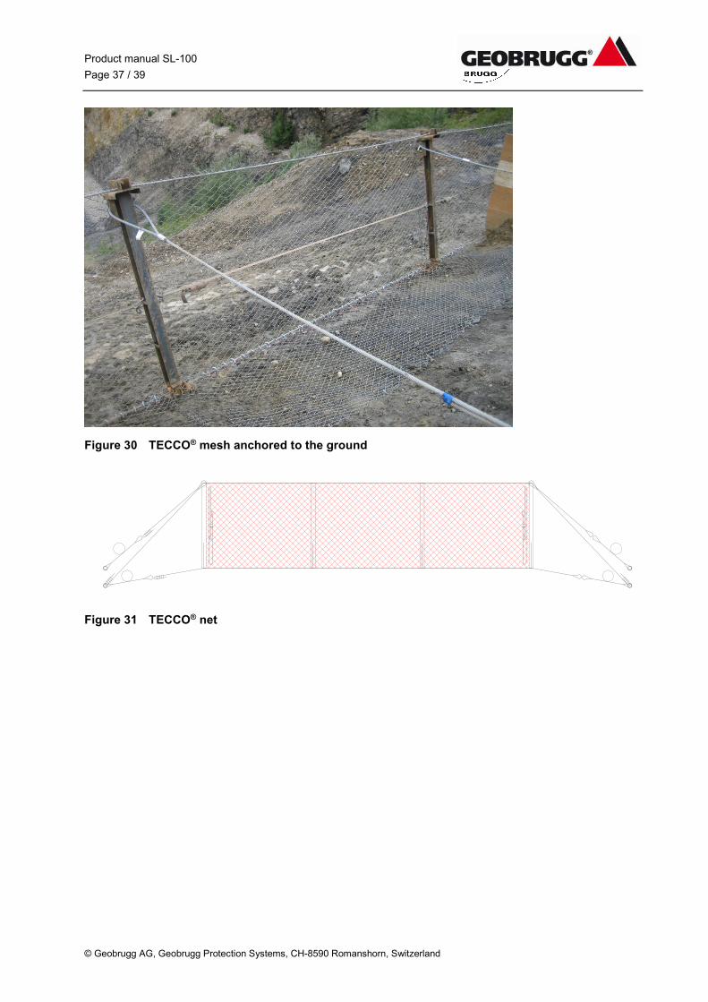
Figure 30 TECCO® mesh anchored to the ground
Figure 31 TECCO® net
Product manual SL-100
Page 38 / 39
© Geobrugg AG, Geobrugg Protection Systems, CH-8590 Romanshorn, Switzerland
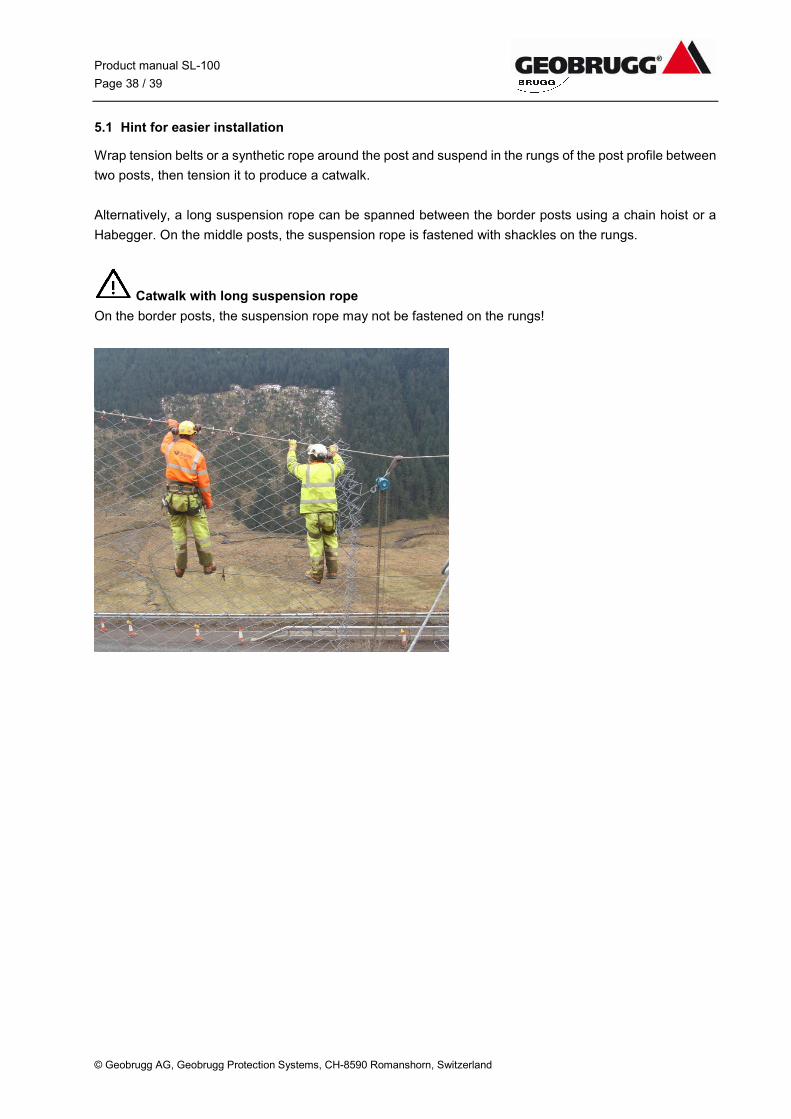
5.1 Hint for easier installation
Wrap tension belts or a synthetic rope around the post and suspend in the rungs of the post profile between
two posts, then tension it to produce a catwalk.
Alternatively, a long suspension rope can be spanned between the border posts using a chain hoist or a
Habegger. On the middle posts, the suspension rope is fastened with shackles on the rungs.
Catwalk with long suspension rope
On the border posts, the suspension rope may not be fastened on the rungs!
Product manual SL-100
Page 39 / 39
© Geobrugg AG, Geobrugg Protection Systems, CH-8590 Romanshorn, Switzerland
6 Final inspection
After completion of the barrier the sire engineer must complete a detailed final inspection.
Above all, the following points must be checked:
a) Are the spiral rope anchors grouted in up to the orange markings?
b) Are the support ropes and lateral anchor ropes connected to the correct anchors?
c) Are the ropes guided correctly on the post head and foot?
d) For the support rope separation, do the bottom support ropes go to the appropriate anchors and not to
the base plates?
e) Has the right number of wire rope clips been used at the end connections of the ropes? Are the wire
rope clips correctly placed?
f) Is the vertical rope installed with two rope clips (50 Nm torque).
g) Check the torque on the wire rope clips on the end connections.
h) Is the TECCO® net roll placed in the right direction (largest diagonal in the horizontal direction)?
i) Are the nets connected to each other correctly?
j) Is the TECCO® net with chain link mesh anchored with nails to the ground?
k) Are the border nets connected to the vertical ropes correctly?
l) Is the sag of the top support ropes less than 3% of the post spacing?


