Sky Commander User's Manual - Charlotte Amateur Astronomers Club
54
Sky Commander XP4 User's Manual Rev 4.1 ©1991, 1995, 2007, 2009 Sky Engineering, Inc All Rights Reserved
Transcript of Sky Commander User's Manual - Charlotte Amateur Astronomers Club
Sky Commander XP4 User's Manual
Rev 4.1
©1991, 1995, 2007, 2009 Sky Engineering, Inc All Rights Reserved

Table of Contents
1 Introduction......................................................................................................... 1
1.1 XP4 New Features..................................................................................... 1 1.2 About this Manual ...................................................................................... 1 1.3 Familiarization............................................................................................ 2 1.4 Battery Replacement ................................................................................. 3 1.5 External 12 Volt Operation......................................................................... 4
2 Unit Setup............................................................................................................ 5
2.1 Setup Menu ............................................................................................... 5 2.2 Determining Encoder Parameters.............................................................. 7
2.2.1 Encoder Resolution .............................................................. 7 2.2.2 Encoder Direction – Dobsonian (Alt-Az) ............................... 7 2.2.3 Encoder Direction – Fork Mount........................................... 8 2.2.4 Encoder Direction – German Equatorial ............................... 9
3 Star Alignment .................................................................................................. 10
3.1 Polar Aligned Scopes............................................................................... 10 3.2 Dobsonian (Alt-Azimuth) Scopes ............................................................. 10 3.3 Fork 2-Star Alignment .............................................................................. 11 3.4 German Equatorial 2-Star Alignment ....................................................... 12
4 Sky Commander Operation ............................................................................. 13
4.1 Setting the Date ....................................................................................... 13 4.2 Basics of Object Location ........................................................................ 14 4.3 Catalog Selection..................................................................................... 16 4.4 Catalog Types.......................................................................................... 17
4.4.1 Numbered Catalogs ........................................................... 17 4.4.2 Named Catalogs................................................................. 18 4.4.3 Named with Constellation Catalogs.................................... 19
5 Operating Menus .............................................................................................. 20
5.1 Search & Identify Menu............................................................................ 20 5.2 Limit Magnitude Menu.............................................................................. 20 5.3 LCD Intensity Menu ................................................................................. 21

5.4 Favorite List Menu ................................................................................... 21 5.5 Purge Favorite List Menu......................................................................... 21 5.6 Battery Monitor Menu .............................................................................. 21 5.7 Realign on Object Menu .......................................................................... 21 5.8 Equatorial Table Reset Menu .................................................................. 22
6 Operating Features........................................................................................... 23
6.1 Display Object Information....................................................................... 23 6.2 Search & Identify ..................................................................................... 24 6.3 Scroll by Constellation and Catalog ......................................................... 24 6.4 Favorite Objects List ................................................................................ 26 6.5 Special Object List ................................................................................... 28 6.6 The Planet Catalog .................................................................................. 29 6.7 Standby Mode.......................................................................................... 29 6.8 Use with Equatorial Table ........................................................................ 29
6.8.1 2-Star Alignment with EQ Table ......................................... 30 6.8.2 Equatorial Table Reset ....................................................... 30
6.9 Realignment on Database Objects .......................................................... 31 6.10 Sidereal Clock.......................................................................................... 31
7 Alignment Stars ................................................................................................ 32
8 XP4 Specifications ........................................................................................... 33
9 Troubleshooting ............................................................................................... 34 Appendix A 90 Degree Setting for GE Type Mounts --------------------------------------37 Appendix B RS232 Serial Port ------------------------------------------------------------------39 Appendix_C Encoder Jack ------------------------------------------------------------------43 Appendix_D Pointing Accuracy ----------------------------------------------------------------- 44 Appendix_E Installing Dob Kit ------------------------------------------------------------------- 46 Warranty ------------------------------------------------------------------------------------------------ 51

__________ Sky Commander XP4 User's Manual __________
3/17/2009 1
1 Introduction Thank you for buying the Sky CommanderXP4 telescope computer system. You have made an excellent choice. If you have not already used a computer equipped telescope, you are in for a pleasant experience that may change forever the way you observe. XP4 was designed especially for those amateurs who would like to be able to locate and observe celestial objects fast and easily. With the aid of Sky Commander XP4 more time can be spent at the eyepiece and less time at the finder scope and sky atlas. Objects are located by entering their catalog number using push buttons. A liquid crystal display shows you the scope's position and lets you 'zero in' to objects. With a little practice you can locate even the hardest to find objects in seconds. You will find that operating the unit is next to intuitive. This and other exciting features described in this manual will help make your nights out under the stars more enjoyable than ever.
1.1 XP4 New Features XP4 builds on the tradition of the original Sky Commander and adds new capability. • New custom ABS plastic enclosure for durability and easier battery replacement. • 4X Memory Size – plenty of room for operating program and 30,000+ database objects. • Flash Memory – Upgrade software and manage database through your PC with Windows based utility program. • Four independent setups for multiple scopes. • Additional Catalog Types – Named object catalogs for deep sky and stars are now supported. Also a Bayer (Greek letter + number) star catalog is available. • Users can select from a list of available catalogs and load only those that are of interest. • Users can create their own catalogs using Microsoft Excel spreadsheet. • Support for third party drive systems such as ServoCat and SiTech in addition to the Sky Engineering Sky Tracker™. In the original Sky Commander program and database changes were done by replacing an EPROM (Electrically Programmable Read Only Memory) device. This required the unit to be opened and was not convenient. XP4 introduces flash memory which can be updated without opening the box. Simply connect it to your PC and run an upgrade utility.
1.2 About this Manual
This manual contains everything you need to know to start using Sky Commander XP4. Parts of the manual are written as a tutorial to help you get familiar with operating the unit. Every feature is described using examples.

__________ Sky Commander XP4 User's Manual __________
3/17/2009 2
1.3 Familiarization
Figure 1 shows the Sky Commander computer. The ON-OFF pushbutton switch is located on the left front of the box. A power jack is available for powering the unit from external 12 volt DC. The unit also operates from an internal 9 volt battery. A six button keypad is used to make selections, navigate menus, etc. Optical encoders for sensing scope motion attach by cable to an 8 pin modular jack (RJ45). A second 6 pin modular jack is used for RS-232 communications to a host PC. It is also used for installing upgrades and changes to the database.
Figure 1 Sky Commander XP4 Computer
The display is 32 character (2 lines of 16 characters) dot matrix LCD (Liquid Crystal Display). It is illuminated with an adjustable yellow-green LED backlight.

__________ Sky Commander XP4 User's Manual __________
3/17/2009 3
1.4 Battery Replacement
The unit has an internal compartment for a 9 volt alkaline battery. When replacement is required, follow the steps outlined below: 1) On the bottom of the unit you will find a slide cover. Push in the direction shown in order to open the battery compartment. If the slide is hard to move, a coin or small screwdriver blade may be used at the point indicated. 2) Remove the battery and attach a new one. 3) When replacing the battery, insert the wire lead side first (wire goes under battery, not next to cover). 4) Replace the plastic slide cover. The end of the cover with the long tab goes to the end of the opening nearest the ON-OFF button. Slide the cover to the closed position.
Slide to Open
Slide to Close
Long Tab This End
ON/OFF Button
Bottom View
Battery Cover
Use small screwdriver to help slide open if needed.
Figure 2 Battery Installation

__________ Sky Commander XP4 User's Manual __________
3/17/2009 4
1.5 External 12 Volt Operation The unit will operate on external 12 volt DC power. The power jack is on the left side. It is a standard 2.1mm ID, 5.5mm OD type. The center contact is positive polarity. WARNING – Use only regulated 12 volt DC power supply or 12 volt battery for external power. A regulated AC to DC adapter for this purpose is available as part number PWR-AC-1210. Use of unregulated adapters will void warrantee External power must be used in cold weather, 10 degrees C and below. It powers a heater to keep the liquid crystal display operating normally. Without the heater, the display response can be very slow, making it difficult to use. External power is also very useful when using the ‘Fast track’ feature. When Fast Track is on, the unit will draw an extra 50 to 100 mA depending on the encoder type and resolution. This will run down an internal 9 volt battery (300 to 400 mAH) quickly. It is not necessary to use an internal 9 volt battery when operating from external power. You can leave the internal 9 volt battery installed however. It will not damage the unit.
__________ Sky Commander XP4 User's Manual __________
3/17/2009 5
2 Unit Setup This chapter deals with getting the unit setup for your particular telescope. If you purchased the unit along with the telescope, the dealer may already have done these steps for you.
2.1 Setup Menu
The purpose of the Setup Menu is to make changes to various parameters such as encoder resolution, i.e. steps per revolution, etc.
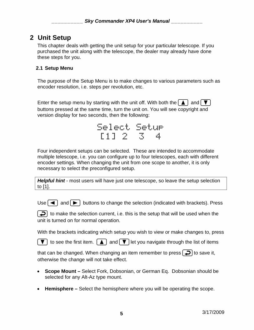
Enter the setup menu by starting with the unit off. With both the and buttons pressed at the same time, turn the unit on. You will see copyright and version display for two seconds, then the following:
Select Setup
[1] 2 3 4 Four independent setups can be selected. These are intended to accommodate multiple telescope, i.e. you can configure up to four telescopes, each with different encoder settings. When changing the unit from one scope to another, it is only necessary to select the preconfigured setup. Helpful hint - most users will have just one telescope, so leave the setup selection to [1].
Use and buttons to change the selection (indicated with brackets). Press
to make the selection current, i.e. this is the setup that will be used when the unit is turned on for normal operation. With the brackets indicating which setup you wish to view or make changes to, press
to see the first item. and let you navigate through the list of items
that can be changed. When changing an item remember to press to save it, otherwise the change will not take effect.
• Scope Mount – Select Fork, Dobsonian, or German Eq. Dobsonian should be
selected for any Alt-Az type mount. • Hemisphere – Select the hemisphere where you will be operating the scope.

__________ Sky Commander XP4 User's Manual __________
3/17/2009 6
• RA Direction – This is the direction for the RA or Azimuth encoder. The
direction, Normal or Reverse, will be determined by doing a simple test with the scope. The default, Normal is the one that is most typical for most Dobsonian scopes. See directions for determining this setting for DOB, Fork, or German Eq.
• Dec Direction – This is the direction for the Declination or Elevation encoder.
The direction, Normal or Reverse, will be determined by doing a simple test with the scope. The default, Normal is the one that is most typical for most Dobsonian scopes.
• RA Encoder Res – This is the number of counts of the encoder per revolution of
the telescope RA or Azimuth axis. Typical values are 4000, 4096, 8000, 8192, 10000, etc.
• Dec Encoder Res – This is the number of counts of the encoder per revolution
of the telescope Declination or Elevation axis. Typical values are 4000, 4096, 8000, 8192, 10000, etc.
Important Note: The resolution numbers entered represent the counts per revolution of the telescope. For instance, if an 8192 step encoder is used for azimuth and 4096 step encoder is used for elevation, then you must enter those numbers. Any gearing or pulley ratio must be taken into account. If a 2048 step encoder is geared 2:1, then enter 4096.
• Fast Track ON/OFF – The Fast Track feature helps the Sky Commander keep
up with fast motion when using higher resolution encoders, 8192 and up. By default it is OFF. Setting to 12V will turn on fast track automatically when external 12 volts is detected. The ON selection will force it on all the time. Note: having Fast Track on uses more power from the battery, so if only internal battery is used, the battery will not last nearly as long.
• Sidereal Clock – This selection should always be ON, unless the scope is a
Dobsonian on a motorized equatorial platform. In this case it should be OFF.
• RS232 Baud Rate – The default is 9600 bits per second. Lower values can also be selected.
• SiTech Mode – The Default is OFF. It should only be turned ON when using the
Sidereal Technology Alt-Az drive system.
__________ Sky Commander XP4 User's Manual __________
3/17/2009 7
2.2 Determining Encoder Parameters
In the previous section you learned how to enter and save setup parameters, including those for the telescope encoders. Unless the telescope manufacturer sets these for you, you will need to set them yourself. Failure to do this will result in very large pointing errors when you attempt to use it for the first time.
2.2.1 Encoder Resolution
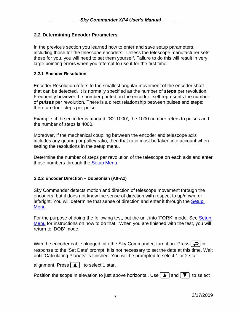
Encoder Resolution refers to the smallest angular movement of the encoder shaft that can be detected. It is normally specified as the number of steps per revolution. Frequently however the number printed on the encoder itself represents the number of pulses per revolution. There is a direct relationship between pulses and steps; there are four steps per pulse. Example: if the encoder is marked ‘S2-1000’, the 1000 number refers to pulses and the number of steps is 4000. Moreover, if the mechanical coupling between the encoder and telescope axis includes any gearing or pulley ratio, then that ratio must be taken into account when setting the resolutions in the setup menu. Determine the number of steps per revolution of the telescope on each axis and enter those numbers through the Setup Menu.
2.2.2 Encoder Direction – Dobsonian (Alt-Az)
Sky Commander detects motion and direction of telescope movement through the encoders, but it does not know the sense of direction with respect to up/down, or left/right. You will determine that sense of direction and enter it through the Setup Menu. For the purpose of doing the following test, put the unit into ‘FORK’ mode. See Setup Menu for instructions on how to do that. When you are finished with the test, you will return to ‘DOB’ mode.
With the encoder cable plugged into the Sky Commander, turn it on. Press in response to the ‘Set Date’ prompt. It is not necessary to set the date at this time. Wait until ‘Calculating Planets’ is finished. You will be prompted to select 1 or 2 star
alignment. Press to select 1 star.
Position the scope in elevation to just above horizontal. Use and to select

__________ Sky Commander XP4 User's Manual __________
3/17/2009 8
a star near the equator like Aldebaran which is about +16 degrees declination. Press
when you see it displayed. The display should look similar to the following:
04h 36m +16.6
Mes_0001 â TAU
Move the scope up toward the zenith. The numbers of declination should increase. If they decrease instead, just note it and proceed. Now move the scope in the counter-clockwise direction. The numbers of RA should increase. If either declination or RA directions are incorrect, go into the Setup Menu and change the direction from Normal to Reverse or visa versa. Repeat the steps above to verify that the changes you made took effect, then return the scope mount setting to ‘DOB’.
2.2.3 Encoder Direction – Fork Mount
Sky Commander detects motion and direction of telescope movement through the encoders, but it does not know the sense of direction with respect to North/South, or East/West. You will determine that sense of direction and enter it through the Setup Menu. The Sky Commander should already be setup for operation in ‘FORK’ mode. If not, then follow directions in the section Setup Menu. Identify the side of the fork that will normally be facing up during alignment and use. This is the side that is up when the scope is pointing to an object on the meridian. Be sure to use this side during the following test and during star alignment.
With the encoder cable plugged into the Sky Commander, turn it on. Press in response to the ‘Set Date’ prompt. It is not necessary to set the date at this time. Wait until ‘Calculating Planets’ is finished. You will be prompted to select 1 or 2 star
alignment. Press to select 1 star.
Position the scope in declination near the equator. Use and to select a star also near the equator like Aldebaran which is about +16 degrees declination. Press
when you see it displayed. The display should look similar to the following:

__________ Sky Commander XP4 User's Manual __________
3/17/2009 9
04h 36m +16.6
Mes_0001 â TAU
Move the scope in the northerly direction. The numbers of declination should increase. If they decrease instead, just note it and proceed. Now move the scope in the easterly direction. The numbers of RA should increase. If either declination or RA directions are incorrect, go into the Setup Menu and change the direction from Normal to Reverse or visa versa.
2.2.4 Encoder Direction – German Equatorial
Sky Commander detects motion and direction of telescope movement through the encoders, but it does not know the sense of direction with respect to North/South, or East/West. You will determine that sense of direction and enter it through the Setup Menu. The Sky Commander should already be setup for operation in ‘GERMN’ mode. If not, follow directions in the section Setup Menu.
With the encoder cable plugged into the Sky Commander, turn it on. Press in response to the ‘Set Date’ prompt. It is not necessary to set the date at this time. Wait until ‘Calculating Planets’ is finished. You will be prompted to select 1 or 2 star
alignment. Press to select 1 star. Position the scope in declination near the equator, and near the eastern horizon in
RA. Use and to select a star also near the equator like Aldebaran which is
about +16 degrees declination. Press when you see it displayed. The display should look similar to the following:
04h 36m +16.6
Mes_0001 â TAU Move the scope in the northerly direction. The numbers of declination should increase. If they decrease instead, just note it and proceed. Now move the scope in the easterly (down toward horizon) direction. The numbers of RA should increase. If either declination or RA directions are incorrect, go into the Setup Menu and change the direction from Normal to Reverse or visa versa.

__________ Sky Commander XP4 User's Manual __________
3/17/2009 10
3 Star Alignment
Each time Sky Commander is turned on, you must go through an alignment procedure so the computer has an orientation to the sky. Sky Commander XP4 supports two alignment methods, 1-Star and 2-Star. The procedure you use depends on the type of mounting your scope has and the accuracy to which it is polar aligned. If the scope is very well polar aligned, only one alignment star is needed. However, if polar alignment is only rough or the scope is Dobsonian type or Alt-Azimuth, then two stars are needed. Note that anytime polar alignment is in question a 2-Star alignment can be done.
3.1 Polar Aligned Scopes
This section describes the 1-Star alignment that can be used on mounts that have been well polar aligned. The 1-Star alignment is the easier of the two procedures since it requires only one sighting. The positioning accuracy of your system however will depend on the accuracy of the polar alignment.
After turning on, select 1-Star alignment with the button. The display will show 'Sight 1st Star' on the top line. The bottom line will show the name of one of 40
alignment stars along with its magnitude. or buttons let you select the star you are going to use. If you have a German Equatorial (NOT FORK) mount and you
want to use a star in the western sky, use the or buttons to change the display to 'Sight 2nd Star'. For fork mounts leave the display at 'Sight 1st Star' for any alignment star, East or West of the meridian. Sight the star with your scope. Get it as close to center of field as possible. When the star is centered, press ENTER. This completes the alignment procedure, and the Sky Commander enters operating mode.
3.2 Dobsonian (Alt-Azimuth) Scopes
To use Sky Commander with a Dobsonian (Alt-Azimuth) scope, a 2-Star alignment must be done every time the unit is turned on. The stars should not be too close to the zenith or horizon. +10 to +60 degrees elevation is preferable. They should be separated in azimuth at least 90 degrees; the more separation, the better.
Two star alignment begins with the 'Sight 1st Star' prompt. Use and

__________ Sky Commander XP4 User's Manual __________
3/17/2009 11
buttons to select the first star. The first one in the list is Polaris. This is usually a good star for northern hemisphere users.
Sight the star with the scope. Be as accurate as possible. Press when you have the star sighted. The display will now prompt with 'Sight 2nd Star'. Select the next star from the list.
Note: The Sky Commander will allow you to select any of the available alignment stars. It is up to you to choose ones that are suitable. Suggestion: Mark the stars on a planisphere for a handy reference. Also choose your alignment stars ahead of time.
Sight this star just like the first, then press ENTER. You have just completed the alignment procedure. The Sky Commander enters operating mode.
3.3 Fork 2-Star Alignment
When you are prompted for 1 or 2-star alignment, select 2-star with . You will be prompted to set the scope to +90 degrees. This means relative to the scope, not the sky. The optical tube should be oriented parallel to the fork arms. The positioning is not very critical, within a degree is fine.
Next you will be prompted to sight the 1st star. Use and buttons to select a convenient star on the eastern side of the meridian. Get the star sighted accurately
in the scope and press . Now you will be prompted for the 2nd star. Choose one on the western side of the meridian (preferably at least 90 degrees from the first).
Again, sight the star and press . This completes the alignment procedure, and the Sky Commander enters operating mode.

__________ Sky Commander XP4 User's Manual __________
3/17/2009 12
3.4 German Equatorial 2-Star Alignment
When you are prompted for 1 or 2-star alignment, select 2-star with . You will be prompted to set the scope to +90 degrees. This means relative to the scope, not the sky. The optical tube should be oriented parallel to the polar shaft of the mount. Note: This setting must be accurate. See the appendix describing the method for determining the +90 degree position for a German Equatorial.
Next you will be prompted to sight the 1st star. Use and buttons to select a convenient star on the eastern side of the meridian. Get the star sighted accurately
in the scope and press . Now you will be prompted for the 2nd star. Choose one on the western side of the meridian (preferably at least 90 degrees from the first).
Again, sight the star and press . This completes the alignment procedure, and the Sky Commander enters operating mode.

__________ Sky Commander XP4 User's Manual __________
3/17/2009 13
4 Sky Commander Operation
All of the Sky Commander functions are accessible through the six button keypad array on the front panel. The buttons are arranged in such a way to make them easily located by feel. The four arrow buttons are for navigating menus and scrolling lists. The remaining two buttons are ENTER, for making selections and MENU, for accessing the menu controls.
Figure 3 - Keypad Buttons
In normal operation the buttons are pressed and quickly released, like dialing on a touch-tone phone. If the buttons are held down for more than about a second however, multiple presses of the button are generated. This can be convenient for scrolling through long lists.
4.1 Setting the Date
The date displayed each time you turn on the Sky Commander is not driven by a 'real time' clock as in a desktop PC. You are able to change and save it as described below however. Setting the date is optional; it is used only for the calculation of planet positions and has no effect on alignment or location of other objects.
Change the date by moving the cursor with and scrolling the month, day and
year with or . Press to save the date and proceed to Star Alignment.
__________ Sky Commander XP4 User's Manual __________
3/17/2009 14
4.2 Basics of Object Location
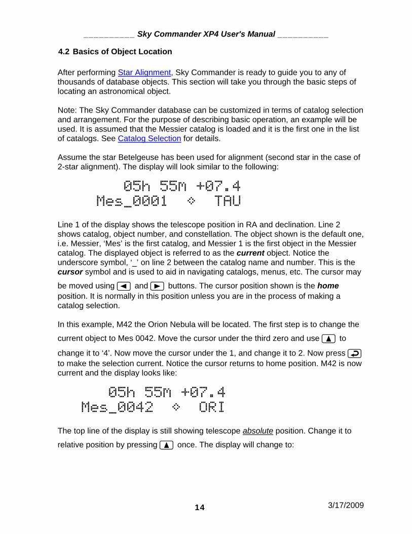
After performing Star Alignment, Sky Commander is ready to guide you to any of thousands of database objects. This section will take you through the basic steps of locating an astronomical object. Note: The Sky Commander database can be customized in terms of catalog selection and arrangement. For the purpose of describing basic operation, an example will be used. It is assumed that the Messier catalog is loaded and it is the first one in the list of catalogs. See Catalog Selection for details. Assume the star Betelgeuse has been used for alignment (second star in the case of 2-star alignment). The display will look similar to the following:
05h 55m +07.4
Mes_0001 â TAU
Line 1 of the display shows the telescope position in RA and declination. Line 2 shows catalog, object number, and constellation. The object shown is the default one, i.e. Messier, ‘Mes’ is the first catalog, and Messier 1 is the first object in the Messier catalog. The displayed object is referred to as the current object. Notice the underscore symbol, ‘_’ on line 2 between the catalog name and number. This is the cursor symbol and is used to aid in navigating catalogs, menus, etc. The cursor may
be moved using and buttons. The cursor position shown is the home position. It is normally in this position unless you are in the process of making a catalog selection. In this example, M42 the Orion Nebula will be located. The first step is to change the
current object to Mes 0042. Move the cursor under the third zero and use to
change it to ‘4’. Now move the cursor under the 1, and change it to 2. Now press to make the selection current. Notice the cursor returns to home position. M42 is now current and the display looks like:
05h 55m +07.4
Mes_0042 â ORI The top line of the display is still showing telescope absolute position. Change it to
relative position by pressing once. The display will change to:

__________ Sky Commander XP4 User's Manual __________
3/17/2009 15
* >344.6 ã 01.7
Mes_0042 â ORI
The asterisk, * symbol on the top left indicates the display is showing telescope relative position, i.e. the difference between telescope absolute position and object position. Arrows on the top are an indication of which way to move the scope to get to the object. Numbers indicate degrees of displacement.
Note: this example is for Alt-Azimuth (Dobsonian) – if the scope is Fork or German Eq, the top line will look like -
* 00h 20m +12.8 indicating hours and minutes of RA displacement, and degrees of declination displacement. You will now move the telescope in azimuth (RA for polar type mounts) and elevation (declination for polar type mounts) to the target object, M42. The right pointing arrow indicates you should move clockwise in azimuth. The down pointing arrow indicates you should move down in elevation. As you move the scope the numbers change. For azimuth, the starting number is greater than 180 degrees, so they increment toward 360 degrees (same as zero) as you get closer to the target. For elevation, the numbers decrease to zero as you get closer. Move the scope until both displacements are zero:
* >000.0 ã 00.0
Mes_0042 â ORI The telescope is now pointing at the target object. If you find that it is not, repeat the alignment procedure (turn power off and on to reset). If there is still a problem, see the section in this manual titled Troubleshooting.

__________ Sky Commander XP4 User's Manual __________
3/17/2009 16
4.3 Catalog Selection
In the last section you learned the basics of object location. The example used the Messier catalog, but Sky Commander can hold many more catalogs, up to 32 including Planet and Special Object catalogs which you will learn about later.
To select other catalogs, move the cursor under the catalog name using the button as shown below:
05h 55m +07.4
Mes 0042 â ORI
Now use button to change to the next catalog, in this example the NGC catalog
05h 55m +07.4
NGC 0001 â PEG
Pressing always returns the cursor to home position and makes the displayed
object current. With the cursor under the catalog name, use and buttons to see other catalogs that make up the database.

__________ Sky Commander XP4 User's Manual __________
3/17/2009 17
The following table is a list of catalogs available at the time of writing this manual. Updated catalogs, when available can be found at http://www.skyeng.com .
Abbreviation Catalog Name Brief Description Number
Mes Messier The famous catalog of Charles Messier 110
NGC New General Catalog Entire NGC Catalog 7800
NDS Named Deep Sky Various types of deep sky objects by common name 135
NST Named Star Stars by common name 142
Dbl Double Stars 600 best double stars provided by Saguaro Astronomy Club 600
Byr Bayer Stars Stars by Greek letter and number 1500
APN Abell Planetary Nebula Large but very faint planetary nebula cataloged by George Abell in 1966.
86
Arp Arp Peculiar Galaxies Complete catalog of Dr Halton C. Arp 338
Brd Barnard Dark nebula 159 Hr4 Herschel 400 Herschel 400 listed by NGC number 400
HIC Hickson Galaxy Clusters A catalog of compact galaxy clusters 100
IC Index Catalog Entire Index Catalog 5250 Brk Berkley Open Clusters 86 Cr Collinder Open Clusters 71
Trm Trumpler Open Clusters 34 S Special Objects User entered coordinates 74
PLN Planets All observable planets 8
Table 1 - Installed Catalogs
4.4 Catalog Types
The way that you access objects within a given catalog depends on the type.
• Numbered • Named • Named with Constellation
4.4.1 Numbered Catalogs
A four digit number appears to the right of the catalog name. The constellation name appears to the far right -

__________ Sky Commander XP4 User's Manual __________
3/17/2009 18
* >000.0 ã 00.0
NGC 4594 â VIR
The cursor can be placed under each digit and the and buttons are used to
change them. Pressing causes the entered object to become current. If an invalid number is accidentally entered, an error message is displayed and the display reverts to the previously selected object.
Object Not Found The cursor may be moved under the constellation name. The constellation can be
changed with the and buttons. Note: Only constellations that contain objects within the current catalog (and the object meets Limit Magnitude criteria) will be selectable. Having selected a constellation, objects of the current catalog can be browsed by
placing the cursor under the â symbol. As the and buttons are pressed, first a brief object description appears, then the object number. The description helps the user decide whether or not it is of interest. See Scroll by Constellation and Catalog
4.4.2 Named Catalogs
There are two catalogs, namely NDS (Named Deep Sky) and NST (Named Star) which allow the user to select in alphabetical order the common name of an object.
* >000.0 ã 00.0
NST Acamar
When the cursor is moved under the first letter of the object name, the and buttons let you increment or decrement to the next letter. You can move quickly to the first letter of the name you are trying to locate. Move the cursor once more to the right
and then scroll to the exact name you want. In this example, press several times to get from ‘Acamar’ to ‘Alberio’.
* >000.0 ã 00.0
NST Alberio

__________ Sky Commander XP4 User's Manual __________
3/17/2009 19
Press to make the object current.
4.4.3 Named with Constellation Catalogs
The Double Star Catalog in particular is organized by name and constellation.
* >000.0 ã 00.0
Dbl Oà 514 AND Positioning the cursor under the name lets you scroll through all the double stars in the current constellation, Andromeda in this case. To get to a different constellation, just move the cursor under the first letter of the constellation name. Scroll to the
constellation with the and buttons. Move the cursor back under the double
star name to continue with your search. Press to make the object current.

__________ Sky Commander XP4 User's Manual __________
3/17/2009 20
5 Operating Menus
More advanced control over operating features, parameters and settings is accomplished through the Operating Menus. To access the operating menus, press
the button once. You will see the first menu item –
Search-ID ON-OFF
< on OFF >
Use the and buttons to get to other menu items. There are eight of them.
• Search & ID • Limit Search Magnitude • LCD Intensity • Favorite List On-Off • Purge Favorite List • Battery Monitor • Realign on Object • Equatorial Table Reset (appears only when sidereal clock is off)
Exit the operating menus by pressing once more.
5.1 Search & Identify Menu
Use and buttons to turn this feature On or Off. See Search & Identify for
description of this feature. Press to return to operating mode.
5.2 Limit Magnitude Menu
Use and buttons to increment or decrement the limiting magnitude. Objects dimmer than this setting will not be displayed during object scrolling operations, or
Search & ID mode. Press to permanently save the setting. You do not necessarily need to save; the setting will still be in effect until the unit is turned off,
even if it is not saved. Press to return to operating mode. Note – a unique Limit Magnitude value is saved for each scope defined in the setup parameters. There are four of them. See Setup Menu. Example – you can set Limit Mag to 13 for your 16” dob, and 10 for your 4” refractor. When you change from one scope to the other, the correct Limit Mag will used.

__________ Sky Commander XP4 User's Manual __________
3/17/2009 21
5.3 LCD Intensity Menu
Use and buttons to select the desired display brightness, LOW, MEDIUM
or HIGH. Press to permanently save the setting. Press to return to operating mode.
5.4 Favorite List Menu
Use and buttons to turn the list On or Off. See Favorite Objects List for
information on this special mode. Press to return to operating mode.
5.5 Purge Favorite List Menu If the ‘Favorite List’ gets cluttered, or corrupted, or you just want to start over, select
YES, using the button and button. The Favorite list will be erased. Press
to return to operating mode.
5.6 Battery Monitor Menu A bar is displayed on the bottom line -
E -BATTERY+ F
ÜÜÜÜÜÜÜÜÜÜÜÜÑ The farther the bar extends to the right, the higher the charge of the battery. Full indicates 9 volts or more, Empty is about 6 volts.
5.7 Realign on Object Menu
While in operating mode, pointing accuracy can sometimes be improved by sighting on a known database object and executing a ‘Realign’. For Dobsonian (Alt-Az) scopes, avoid realigning on objects higher than about 60 degrees, i.e. use the same criteria for selecting the realign object as you use to select the initial alignment stars. Be sure the object is current on the display and center it in the eyepiece. Go to the
‘Realign on Obj’ menu and press . Sky Commander will automatically exit the menu display. The offset should now be zero on each axis –
* >000.0 ã 00.0
Mes_0042 â ORI If the offset is not exactly zero, you can execute the realign command once more. See section titled Realignment on Database Objects

__________ Sky Commander XP4 User's Manual __________
3/17/2009 22
5.8 Equatorial Table Reset Menu
If your scope is a Dobsonian and you are using an equatorial table, you will need to use the Table Reset menu. It allows you to reestablish alignment after physically resetting the table. You do not have to do another star alignment. Use the following setup and alignment procedure: 1. Polar align the table as accurately as possible. 2. Sidereal clock must be turned off. See Setup Menu. 3. When you are ready to do the initial 2-star alignment, turn the table on and then bring it to the reset position. At the same time turn the Sky Commander on. These two operations should be done simultaneously or as nearly so as possible. The table must be running during alignment, and must not slip. Perform the 2-star alignment (see Alt-Az Alignment). You are now ready to observe. 4. To assure accuracy of the setting circles, leave the table running. 5. At some point it will be necessary to reset the table. When you are ready to do this, perform the following steps:
Press: to get to menu screens
or to get to Equatorial Table Reset. Bring table back to reset position. The table must be running.
Press immediately.
Press to return to normal operation. Important Note: if you suddenly encounter poor pointing accuracy during operation, the table may have slipped. If this happens, there is no need to do another two star alignment, simply reset the table as described above. Do not use the ‘Realign to Object’ function until you have eliminated table slippage as the cause of pointing error.

__________ Sky Commander XP4 User's Manual __________
3/17/2009 23
6 Operating Features
6.1 Display Object Information
While the cursor is in ‘Home’ position, pressing will display basic information about the current object. For instance, go to the Messier catalog, ‘Mes’. Change the
number to 0027 and press to make it current.
Mes_0027 â VUL
The cursor reverts back to home position. Now press to display information –
Planet Neb +07.3
M27 is a planetary nebula of magnitude 7.3. Press again, and the display goes back to showing the object catalog and number again. Information about double stars is different. Example, select the double star catalog ‘Dbl’ and scroll to the constellation of Andromeda, ‘AND’. With the cursor under the star name, scroll to -
Dbl Oà 514 AND
Press to make it current, then press to show the information -
7.1/ 9.5 005" The double star is primary magnitude 7.1, secondary magnitude 9.5 and 5 arc second separation. For other star catalogs, such as Named Star (NST) and Bayer Star (Byr), the star magnitude and spectral type is displayed –
Example, for Byr_ALPHA AND, the following info is displayed –
2.1/ B8/ Alpha Andromeda (Alpheratz) is a 2.1 magnitude star of spectral type B8.

__________ Sky Commander XP4 User's Manual __________
3/17/2009 24
6.2 Search & Identify
Sky Commander has the ability to identify objects you come across while panning the scope. Enable Search & ID through the Operating Menu – see Search & Identify Menu. As you move the scope, any object brighter than the Limit Magnitude, which is within a .5 degree circle is displayed. If multiple objects qualify, the closest one is displayed. While Search &ID mode is on, an ‘S’ is displayed in the upper left of the display as a reminder to the user –
S* <000.3 ä 00.2
Mes_0081 â UMA All loaded catalogs except ‘Special Objects’ and Planets are searched. If no object is found meeting the criteria, the following message is displayed –
Searching Data Power consumption is slightly higher while in Search & ID mode.
6.3 Scroll by Constellation and Catalog
You may have noticed the diamond symbol, â that appears with most catalogs. Positioning the cursor under the diamond allows you to browse through objects in the current catalog that are also in the current constellation (shown to right of diamond).
While the cursor is under the diamond, use the and buttons to scroll through the list. The description of each object is displayed briefly before the display reverts to showing the object number. This gives you the ability to quickly sort objects such as bright galaxies, clusters, etc. Note - the objects displayed while in this mode are limited to those brighter than the Limit Magnitude. Example: Make the NGC catalog current and move the cursor under the diamond. The default constellation is Pegasus because NGC 0001 is in that constellation.
NGC 0001 â PEG

__________ Sky Commander XP4 User's Manual __________
3/17/2009 25
Use the and buttons to browse the NGCs of Pegasus. Notice there are many dim galaxies, but also a few bright ones. For instance, as you scroll, you may see –
Galaxy +10.6 10.6 is the magnitude. The display then reverts to showing the object number –
NGC 7814 â PEG
To move to a different constellation, simply move the cursor under the constellation
name (far right bottom line) and use the and buttons to select a new one. Note – if a constellation does not contain objects of the current catalog, it will not be selectable.
With the cursor under ‘PEG’, press twice to get to the constellation Orion (ORI)
NGC 1661 â ORI
Again, move the cursor under the diamond and scroll with and buttons. Notice there are many bright nebulas and clusters to choose from. You may see something like –
Open Clstr +04.2 Then the display reverts to –
NGC 1981 â ORI

__________ Sky Commander XP4 User's Manual __________
3/17/2009 26
6.4 Favorite Objects List
Objects from the internal database can be marked as ‘Favorite’ and put into a list for quick reference. Another possible use is to record your evenings observations. When
the cursor is in the home position on the bottom line of the display, pressing will cause the following prompt –
Add to Fav List?
< yes NO > If you wish to add the object to the favorite list, move the cursor under YES, and
press . Otherwise just press and the object will not be saved. A maximum of 73 objects can be saved to the favorite list. If you try to save more than the maximum, an error message is displayed –
Fav List Full
Also, if the object is already in the list, you will see –
Already in List
When you want to access an object that was stored in the favorite list, the list must be
turned on. Go to the operating menus ( ) and index to the ‘Favorite List’ menu. See Favorite List Menu. Turn on the list by moving the cursor under ON, then press
again to exit menus. If you forgot to put any objects into the list, the following error message is displayed –
Fav List Empty
Otherwise you should see something like the following –
F* <038.1 ã 15.7
Mes_0021 â SGR The ‘F’ on the top line indicates that the ‘Favorite’ list is active. In this example, M21
is in the list. Other favorites are accessed using the and buttons. While the

__________ Sky Commander XP4 User's Manual __________
3/17/2009 27
list is active, these buttons are dedicated to scrolling the list.
While the list is in use, objects may be deleted. Press and the following prompt is displayed –
Del Fav List ?
< yes NO >
Move the cursor under YES and then press to delete it. Otherwise just press
and it will not be deleted.
To delete the entire favorite list, see operating menu item - Purge Favorite List Menu.

__________ Sky Commander XP4 User's Manual __________
3/17/2009 28
6.5 Special Object List
You may wish to reference object coordinates other than those included in the catalogs. The Special Object list provides an easy way to do just that. You can enter up to 59 coordinates by Right Ascension and declination. This can be done either through the keypad on the Sky Commander or through a PC program via the RS232 port. See Load Special Object Coordinates Command in Appendix B.
To see the Special Object list, move the cursor under the catalog name and use
or to get to the catalog named with a single ‘S’ as shown below –
05h 14m -08.2
S 00 00h00m+00.0 The two digits following ‘S’ are object index. Put the cursor under the first digit and
use or to scroll the list. The index range is 00 to 58. There is also a ‘99’ index which is explained below. Return to index ‘00’ and then move the cursor under the first digit of RA hours. Use
or to change this digit then move to the next digit, changing it as well. Continue to move the cursor to the right, changing digits as desired. When you are
done entering the special object coordinates, press to save it in EEPROM memory. The information will be retained even after turning the Sky Commander off. Special objects are located just as other catalog objects, i.e. with the cursor in home
position, the button toggles on and off the * so you can ‘zero in’ to the target. Entering of object information other than coordinates is not supported, so it is a good idea to keep your own list with that type of information. Special object coordinates can also be uploaded from a PC program using the RS232 port. See Appendix B for information on serial protocol. Special object ‘99’ is to be used by PC software to upload coordinates ‘On the Fly’. It is not saved in EEPROM, so any changes to it through the keypad or PC will be lost after the Sky Commander is turned off.

__________ Sky Commander XP4 User's Manual __________
3/17/2009 29
6.6 The Planet Catalog
The planet catalog is a bit different than the other catalogs because the positions are calculated during initialization when the Sky Commander is turned on. Positions are based on the date that the user enters. Since there is no time entry other than date, it is best to set the date one day ahead – i.e. if it is the evening of June 1st, set the date to June 2nd. The reason is that the calculations assume 0 hours universal time for the given date. For instance, in early evening (US) the time is much closer to 0 hours UT of the following day than it is to 0 hours UT of the present day.
Press button to move the cursor under the catalog name and then index to the
PLN catalog using the and buttons. The display should look something like
* >032.1 ã 19.3
PLN_ Mercury Now move the cursor over by the planet name with the button and index to a
different planet with the and buttons. returns the cursor to home position.
6.7 Standby Mode
During an observing session there will be times when you are not actively using the Sky Commander. It is a good idea to put the unit into standby to save battery power and turn out the display backlight. Standby is activated by a quick double press of the
button. The display shows –
Standby Mode
and the backlight goes out. While in standby, encoder alignment is maintained, even if the scope moves. Press any button to return the unit to normal operation.
6.8 Use with Equatorial Table
An equatorial table is one way to give Dobsonian scopes tracking ability. The scope is mounted atop the table which is driven with a clock drive. When properly polar aligned, the table cancels out the motion of the earth, thus making all celestial objects stationary in the eyepiece.
__________ Sky Commander XP4 User's Manual __________
3/17/2009 30
In the normal case (no table), Sky Commander uses an internal sidereal clock to keep pace with the apparent motion of the sky. When used with a table, it is only necessary to turn the clock off. See ‘Sidereal Clock’ under - Setup Menu . Also see Equatorial Table Reset Menu
6.8.1 2-Star Alignment with EQ Table Even though the table is ‘equatorial’, it is still necessary to perform a 2-star alignment since the scope is moving on axes which are not polar. When doing the alignment it is necessary to follow the steps below –
• The table must be well polar aligned. • Sky Commander sidereal clock is turned off. • Turn the table on and bring it to the mechanical start position. At the same
time turn the Sky Commander on. These two operations should be done simultaneously or as nearly so as possible. Perform the 2-star alignment.
• During the alignment procedure the table must not slip. If it does slip, you must start over.
The equatorial table must continue to run and must not slip during the observing period. If however, the table stops, or slips, it is NOT necessary to repeat the two star alignment. If this happens, just perform the table reset procedure described below.
6.8.2 Equatorial Table Reset
When it becomes necessary to do a mechanical reset of the table, or the table stops or slips, do the following –
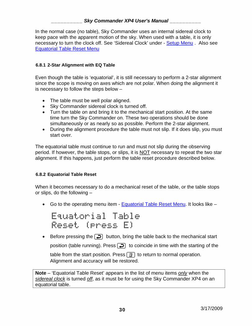
• Go to the operating menu item - Equatorial Table Reset Menu. It looks like –
Equatorial Table
Reset (press E)
• Before pressing the button, bring the table back to the mechanical start
position (table running). Press to coincide in time with the starting of the
table from the start position. Press to return to normal operation. Alignment and accuracy will be restored.
Note – ‘Equatorial Table Reset’ appears in the list of menu items only when the sidereal clock is turned off, as it must be for using the Sky Commander XP4 on an equatorial table.

__________ Sky Commander XP4 User's Manual __________
3/17/2009 31
6.9 Realignment on Database Objects
For various reasons, pointing accuracy may not always be as good as it should be. The ‘Realign on Object’ feature can help correct that condition. By carefully centering a database object in the eyepiece and then telling the Sky Commander to realign to it, a poor alignment can be improved. First, make sure the object you are aligning to is the same one showing on the Sky Commander display.
Press: to get to menu items, then or to get to ‘Realign on Obj’ menu. Center the object in the eyepiece.
Press to complete the realign function. ‘OK’ is displayed briefly before normal operating mode is resumed. Note – When selecting an object for realign, use the same criteria as you do when selecting initial alignment stars, i.e. not too close to the zenith for Dobsonian scopes, or not near the celestial poles for polar aligned scopes.
6.10 Sidereal Clock
Sky Commander has a built in clock to keep pace with the apparent motion of the sky. For most scopes and mountings, the Sidereal Clock should be ON. Only when using a Dobsonian scope with an equatorial table, should it be turned OFF. See the section Setup Menu for instructions on navigating to this menu item. It appears as follows –
Sidereal Clock
< ON off >
Select the desired setting using or button, then press to save.
__________ Sky Commander XP4 User's Manual __________
3/17/2009 32
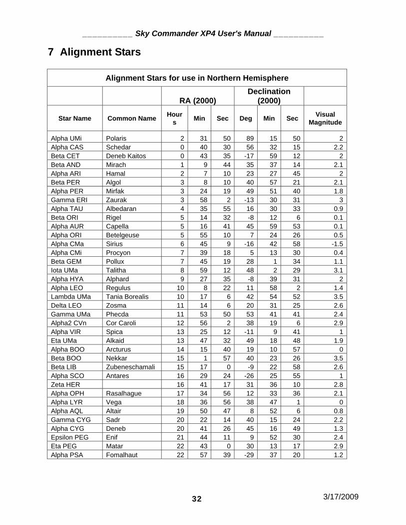
7 Alignment Stars
Alignment Stars for use in Northern Hemisphere
RA (2000) Declination
(2000)
Star Name Common Name Hours Min Sec Deg Min Sec Visual
Magnitude
Alpha UMi Polaris 2 31 50 89 15 50 2Alpha CAS Schedar 0 40 30 56 32 15 2.2Beta CET Deneb Kaitos 0 43 35 -17 59 12 2Beta AND Mirach 1 9 44 35 37 14 2.1Alpha ARI Hamal 2 7 10 23 27 45 2Beta PER Algol 3 8 10 40 57 21 2.1Alpha PER Mirfak 3 24 19 49 51 40 1.8Gamma ERI Zaurak 3 58 2 -13 30 31 3Alpha TAU Albedaran 4 35 55 16 30 33 0.9Beta ORI Rigel 5 14 32 -8 12 6 0.1Alpha AUR Capella 5 16 41 45 59 53 0.1Alpha ORI Betelgeuse 5 55 10 7 24 26 0.5Alpha CMa Sirius 6 45 9 -16 42 58 -1.5Alpha CMi Procyon 7 39 18 5 13 30 0.4Beta GEM Pollux 7 45 19 28 1 34 1.1Iota UMa Talitha 8 59 12 48 2 29 3.1Alpha HYA Alphard 9 27 35 -8 39 31 2Alpha LEO Regulus 10 8 22 11 58 2 1.4Lambda UMa Tania Borealis 10 17 6 42 54 52 3.5Delta LEO Zosma 11 14 6 20 31 25 2.6Gamma UMa Phecda 11 53 50 53 41 41 2.4Alpha2 CVn Cor Caroli 12 56 2 38 19 6 2.9Alpha VIR Spica 13 25 12 -11 9 41 1Eta UMa Alkaid 13 47 32 49 18 48 1.9Alpha BOO Arcturus 14 15 40 19 10 57 0Beta BOO Nekkar 15 1 57 40 23 26 3.5Beta LIB Zubeneschamali 15 17 0 -9 22 58 2.6Alpha SCO Antares 16 29 24 -26 25 55 1Zeta HER 16 41 17 31 36 10 2.8Alpha OPH Rasalhague 17 34 56 12 33 36 2.1Alpha LYR Vega 18 36 56 38 47 1 0Alpha AQL Altair 19 50 47 8 52 6 0.8Gamma CYG Sadr 20 22 14 40 15 24 2.2Alpha CYG Deneb 20 41 26 45 16 49 1.3Epsilon PEG Enif 21 44 11 9 52 30 2.4Eta PEG Matar 22 43 0 30 13 17 2.9Alpha PSA Fomalhaut 22 57 39 -29 37 20 1.2

__________ Sky Commander XP4 User's Manual __________
3/17/2009 33
8 XP4 Specifications
PARAMETER CONDITIONS SPECIFICATION
9 volt Internal Battery 5.5 volts Minimum Operating Voltage
External DC Supply 11 v Min, 13.8v Max
Internal 9v battery, Fast Track off. 10 mA typical
External DC Supply, Fast Track on, 4000 step encoders 90 mA typical Supply Current
External DC Supply, display heater on Additional 120mA
Battery Life Internal 9v battery, Fast Track off. 30 Hours with typical use
DC Power Jack 2.1mm ID, 5.5mm OD power jack, center positive.
Encoder Type Optical Rotary, US Digital type S1 and S2
Fast Track Off 1200 steps / sec Max. Max Rotational Speed
Fast Track On 2000 steps / sec Max.
Encoder Resolution Includes any gearing ratio 32767 (215-1) Max
Operating Temp Internal 9v battery, no heater. +10C to 50C
External DC Supply with heater on -25C to 50C
RA - Declination mode 1 min RA, .1 deg declination. Displayed Resolution
Alt - Azimuth Mode .1 deg Azimuth, .1 deg elevation
Display Type 2x16 char high contrast super
twist LCD, yellow/green backlight. Adjustable intensity.
Serial Port 300 to 9600 baud 1 start bit, 8 data bits, no parity, 1 stop
bit.

__________ Sky Commander XP4 User's Manual __________
3/17/2009 34
9 Troubleshooting Your Sky Commander computer was checked out fully before shipping. Should you experience difficulty, please refer to the following trouble chart before calling for assistance.
TROUBLE CORRECTIVE ACTION
No display indication when unit is turned on.
Check internal battery and connection. Try external 12V power.
No display backlight visible. Adjust intensity with keypad. Light is intentionally dim for night use.
Either RA or dec readout does not change when scope is moved.
Check connections to encoder. Inspect contacts of encoder jack on Sky Commander unit. Look for bent or out of place pins. Inspect encoder cable ends closely. Damaged ends can cause bad electrical contact. Try switching encoders to isolate problem, i.e. determine if problem is encoder or cable or unit.
Objects cannot be found Check direction and resolution settings for each encoder. Objects may be too dim. Be sure to correctly identify alignment stars.
Position accuracy poor
Check resolution setting for each encoder. Check centering of encoders. Check orthogonality of axes and optical collimation. Center alignment stars accurately.
Other position accuracy problems
Perform 360 degree rotation test (see below).
Position accuracy degrades with time.
Check that the sidereal clock is turned on. Check encoders to make sure they are not slipping. Do not move scope too fast.
RA or Azimuth reading seems to stop counting when turning scope counter-clockwise, but may be OK in clockwise direction.
Azimuth pivot pin may not be tightly secured to ground board. Retighten. Pivot pin may be binding if not mounted perpendicular. Pivot pin may be too short, causing binding. Try to remount. Use lubricant on pin/bushing if necessary.
Unit does not work when used with Sky Tracker Dobsonian drive system
Check connection between Sky Commander and Sky Tracker box. Make sure Sky Commander RS232 baud rate is set to 9600.

__________ Sky Commander XP4 User's Manual __________
3/17/2009 35
360 Degree Rotation Test - Do this test if you cannot find any mechanical or electrical connection problems with the encoders. It is not necessary to have the scope outside to do this test. 1) Put the unit into FORK mode and turn OFF sidereal clock (see Setup Menu). These settings are only for the test. Remember to restore the original settings after the test is done. 2) Turn the unit on and position the (Dob) scope roughly horizontal. When prompted for 1 or 2 star alignment, select 1 star.
3) Select a star near the equator like Betelgeuse (+7.5 North) and press to align on it. 4) Establish a mechanical reference point in azimuth. This can be any fixed object in the room. Move the scope to the reference position and note the azimuth (or RA) number on the display. 5) Move the scope as you would normally in azimuth, making several complete rotations, first in clockwise direction and then counter clockwise direction. If you move slightly in elevation, it is OK. Each time the scope comes to the reference point, note the number displayed. It should always be the same as the first reading. This completes the azimuth test. 6) Move the scope in elevation to its lowest point. There should be some kind of mechanical stop. Note the elevation (declination) number. Now move to the zenith stop point and note that number. The two numbers should be roughly 90 degrees apart allowing for the fact the mechanical stops may not be exactly 90 degrees apart. Also allow for negative numbers at the horizontal position and overshooting +90 degree reading at the vertical position. 7) Move the scope in elevation between the two stops and note that the readout returns to the recorded numbers at the stop points. This completes the elevation test.

__________ Sky Commander XP4 User's Manual __________
3/17/2009 36
Technical Assistance Technical assistance is available to all customers free of charge. Normal business hours are from 7:00 PM to 10:00 PM EST Mon-Sat. Leave message if necessary. By Phone – (954)345-8726 E-Mail – [email protected] Web Site – http://www.skyeng.com Orders and other correspondence: Sky Engineering Inc 4613 N University Drive #351 Coral Springs, FL 33067

__________ Sky Commander XP4 User's Manual __________
3/17/2009 37
Appendix A Method of Determining 90 Degree Setting for GE Mounts The advantage of the 2-star alignment is in not having to be polar align. Whenever a 2-star alignment is done, the user is required to orient the scope to '+90 degree declination' (except for Dobsonians). It is important to understand that this position is relative to the telescope itself and not the sky. The 90 degree position is achieved by having the optical axis of the scope parallel to the scope's polar axis. The Sky Commander computer uses a unique Auto-Lock method whereby the +90 degree point is found by computation based on the sighting of the two alignment stars. You are only required to set the position to within about a degree or so. Thus, one opportunity for error is eliminated. Auto-Lock applies only to fork mounted scopes. It does not apply to German equatorials. This means that the +90 degree setting must be done with some precision for a German equatorial. Fortunately there is an easy method to locate the +90 degree point on a German equatorial. Perform the following steps: 1) Collimate the telescope as accurately as possible. 2) Position the scope with the polar axis pointed toward Polaris (not the actual celestial pole). Polaris is used because is relatively stationary. 3) Put the scope in top position (dec axis vertical as viewed from front). Adjust the elevation of the mount so that Polaris passes through the center of field as the scope is moved left and right on the dec axis. Use a medium power eyepiece (preferably one with an illuminated reticle). 4) Now put the scope in side position (dec axis horizontal) on the west side of the mount. Adjust the mount left and right until Polaris moves through the center of field as the scope is moved up and down on the dec axis. 5) Flip the scope to the opposite side of the mount (dec axis again horizontal). See how close Polaris comes to center of field as you sweep on the dec axis. 6) If Polaris cannot be centered, it means that the optical axis is not square with the dec axis. Shim the optical tube as required to correct the error. Take up just half the error as seen in the eyepiece, otherwise you will be off in opposite direction when you flip the scope to the other side. You will have to make a small azimuth adjustment as well each time you adjust the shim. Repeat steps 4-6 until Polaris is centered on both sides of the mount. 7) Bring the scope to top position once more. Move on the dec axis to bring Polaris to

__________ Sky Commander XP4 User's Manual __________
3/17/2009 38
the center of field. If it is a little high or low, don't worry but make sure it is centered left to right. 8) Now adjust the mechanical declination setting circle to exactly 90 degrees and lock it down well. If there is no mechanical setting circle, some means should be employed to locate this exact position when it is needed.

__________ Sky Commander XP4 User's Manual __________
3/17/2009 39
Appendix B RS-232 Serial Port The serial port is used for communications with a PC during normal use and also for the purpose of flash memory upgrade.
• Connector and Pin Assignment
The serial port is located on the rear panel of the unit. It is a 6-pin RJ11 type modular jack .
Figure 4 - RS232 Serial Port
Pin functions are as follows:
RJ11 Pin DB9 Pin Function 1 NC Used for flash upgrade, do not use in normal operation 2 5 Ground 3 NC Alternate 12V Power input for Sky Commander 4 2 Data from Sky Commander to PC 5 3 Data from PC to Sky Commander 6 NC Used for flash upgrade, do not use in normal operation
DB9 pins refer to the serial connector of a Personal Computer. Note – PCs that do not have serial ports can use USB to serial (COM port) adapter cables.
A number of commercially available programs for the PC will communicate with the Sky Commander. These programs allow you to display a section of the sky centered on the position of the telescope. This can be convenient when hopping from one object to others nearby.

__________ Sky Commander XP4 User's Manual __________
3/17/2009 40
• Line Settings When connecting with a PC, use the following line settings –
• 1 start bit • 8 data bits • No parity • 1 stop bit • Flow Control - None
Available baud rate settings are 300, 600, 1200, 2400, 4800, and 9600 bits per second. See section Setup Menu for information on how to set the Sky Commander baud rate. This rate must match the rate selected on the PC. • Command Protocol
Some users may wish to write their own programs to interface with Sky Commander. For this you will need to understand the data format that is used. This section describes the various commands.
• Request Position Command ‘0X0D’
Whenever the program needs updated coordinates it sends a carriage return character (hexadecimal 0D) to the Sky Commander. The program will then receive a 16 character ASCII string. The format is as follows:
[1] space [2,3] integer part of RA hours [4] fixed decimal point [5-7] fractional part of hours [8] space [9] + or - for declination [10,11] integer part of declination [12] fixed decimal point [13-15] fractional part of declination [16] NULL character to terminate string
Example: _12.345_+67.890 (underscore represents a space character, 0X20). The fractional part of the number is treated as a fractional part of an hour, e.g. 4.25 is 4 hours 15 minutes. The same applies to declination. Most programming languages provide an easy means to convert the string to floating point variables.

__________ Sky Commander XP4 User's Manual __________
3/17/2009 41
• Load Special Object Coordinates Command
Coordinates of special objects can be uploaded to the Sky Commander from a PC using the following command:
Lxx_hh.hhh_+dd.ddd[CR]
o xx=special object ID number (00 through 58 and 99 valid) o '_' = space character. o hh.hhh= RA hour and fractional part thereof. o +dd.ddd= Declination (with sign) and fractional part. o [CR] = carriage return character.
Sky Commander will respond with ASCII 'A' for acknowledge. For object IDs 00 through 58, the coordinates are stored in EEPROM (Electrically Erasable Programmable Read Only Memory) and are permanent until overwritten. If object ID number 99 is used, the data is stored in RAM (Random Access Memory) and is only valid until the unit is turned off.
• Read Special Object Coordinates Command
To read back special object coordinates stored in the Sky Commander, use the following command: ?xx where xx=special object ID number (00 through 58 valid). Sky Commander will respond with: hh.hhh +dd.ddd[CR].
• Object Offset Command ASCII ‘O’
Azimuth and elevation offsets (distance to current object) can be obtained with the single character 'O' command. This is useful when the telescope is to slew automatically to the current object.
Sky Commander responds with eight binary bytes (not ASCII). The bytes represent two floating point numbers. The first number is the elevation offset, +=Go Up. The second of the two numbers is the azimuth offset, +=Go CCW. Both numbers are in units of degrees. See section Floating Point Format below for a full description.

__________ Sky Commander XP4 User's Manual __________
3/17/2009 42
• Drive Rates Command ASCII ‘R’
Sky Commander calculates the azimuth and elevation drive rates required to track an object. The single letter 'R' command is used. Sky Commander responds with eight binary bytes representing two floating point numbers. The first number is the elevation rate and the second is the azimuth rate. Positive numbers indicate the telescope should move UP (for elevation) or go CCW (for azimuth). Units are in degrees/minute.
• Field Rotation Command ASCII ‘F’
While tracking an object in azimuth and elevation, the field will rotate slowly, limiting photographic exposure times. The rate of rotation depends on where the telescope is pointing. Sky Commander calculates and reports field rotation in response to the 'F' command. A single floating point number, four binary bytes is returned. The sign is arbitrary since the number of mirrors in the optical system will affect the direction of rotation. Units are in degrees/minute.
• Floating Point Format
Numbers that are returned in response to various commands are expressed in IEEE floating point format as described below: Each number consists of four bytes (32 bits) with the most significant byte sent first. The bits are assigned the following meaning: 31: sign of mantissa, 1=negative. 30-23: exponent, biased by 128. 22-0: mantissa, 24 bits, MSB hidden and always=1. The mantissa is normalized, 24 bits with the MSB hidden. The MSB is always assumed to be 1, therefore only 23 bits are needed to store the mantissa. The exponent is biased by 128; i.e. a 128 value represents an exponent of zero. A 129 value is an exponent of 1. Example: if the exponent has a 131 value (+3), the number is 2^3 * (mantissa). The mantissa is always less than one, and greater than or equal to 1/2. The number zero is stored as four zero bytes.

__________ Sky Commander XP4 User's Manual __________
3/17/2009 43
Appendix C Encoder Jack 1 2 3 4 5 6 7 81 2 3 4 5 6 7 8
Figure 5 - RJ45 Encoder Jack
RJ45 Pin Function 1 Azimuth (or RA) Channel B Signal 2 Azimuth Encoder +5V Power 3 Azimuth Channel A Signal 4 Ground 5 Elevation (or Declination) Channel B Signal 6 Elevation Encoder +5V Power 7 Elevation Channel A Signal 8 Ground

__________ Sky Commander XP4 User's Manual __________
3/17/2009 44
Appendix D A Discussion of Pointing Accuracy You have purchased a sophisticated computer system with high resolution motion encoders. You would hope to be able to pinpoint objects with it when you 'zero-in'. Still, you may find that for one reason or another, there are inaccuracies in pointing. Even after carefully following alignment procedures you still have to fish around a little to find the object. This section is a discussion of factors that influence pointing accuracy. To start with, consider the telescope itself. Whether it has an equatorial mount or an alt-azimuth, it moves on two axes. Ideally, these axes are orthogonal or perpendicular to each other. The reason for this stems from the fact that celestial coordinates are based on a polar system that is orthogonal in itself. An equatorial telescope can never be truly polar aligned unless its axes are orthogonal. While alt-azimuth telescopes are never physically polar aligned, it is nonetheless important to have orthogonality where digital setting circles are concerned. All of the calculations done in the Sky Commander computer are based on orthogonal coordinates. The effect of not having orthogonality is that the computer receives slightly distorted position information. Even though the encoders are installed perfectly and give the exact angular position of each shaft or axis, if the axes are not orthogonal, the computed position may not match the true position, hence a pointing error. Besides the problem of orthogonality between the two main axes, there is the question of orthogonality between the declination (or elevation) axis and the scope's optical axis. This likewise can cause pointing errors with an effect similar to that noted above. The two misalignments though independent of each other can be difficult to distinguish when trying to correct. Always collimate the tube assembly before trying to 'square' it with the declination (or elevation) axis. Dobsonian telescopes in particular can exhibit a 'wobbling' of the azimuth axis caused by non-flatness of the bottom of the rocker box. It is not difficult to understand how this can contribute to pointing errors. It can easily be checked with a straightedge. If either of the two encoders is mounted off the center of rotation there will be some error, for instance if the elevation encoder on a Dobsonian is not mounted in the center of the bearing disk, an error due to 'runout' is experienced. The encoders themselves have a certain angular resolution. This is the smallest movement that can be detected. Resolution itself is a source of error when aligning and in normal use. Though small, it can add to other errors. Always take time to center alignment stars in the eyepiece. This obvious source of error should not be overlooked. Remember the axiom sometimes referred to as GIGO or

__________ Sky Commander XP4 User's Manual __________
3/17/2009 45
‘Garbage In Garbage Out’. Whenever a computer is given erroneous data input, you can expect erroneous data output. The computer itself contributes little if any error. All calculations are done in single preci-sion floating point with six or seven digit accuracy, more than is required. Star and deep sky object coordinates are stored in the computer's memory to the nearest .01 degree. Remember that you can use the 'Realign on Object' feature to improve pointing accuracy. See Realignment on Database Objects.

__________ Sky Commander XP4 User's Manual __________
3/17/2009 46
Appendix E Installing the ALT-AZ-1000 Kit
Figure 6 - Dob Kit (encoders not included) Important Note: Before performing the following procedure, make certain that there is at least 1-3/8" clearance between the inside bottom surface of the rocker box and the front bottom corner of the mirror box as it swings past the rocker box center (pivot point). Insufficient clearance will result in damage to the azimuth encoder.
Azimuth: 1. Cut a 1-1/4" hole in the bottom center of the rocker box. A hole saw works very well for this operation. One can be obtained at almost any hardware store for about five dollars. If a hole already exists, it is a good idea to plug it up first with a piece of wood dowel so that the hole saw has something to keep it centered. Try to keep the drill as

__________ Sky Commander XP4 User's Manual __________
3/17/2009 47
perpendicular as possible to the wood surface. Exact centering is not critical. 2. Press the 1" bronze bushing (1-1/4" OD) into the hole from the top. DO NOT hit it directly with a hammer since it will deform easily. If it will not press in by hand, use a piece of rough sandpaper or a rasp to enlarge the hole slightly. If the bushing is loose in the hole, use some quick set epoxy. Be sure that the flange of the bushing is resting flat on the wood surface as the epoxy sets up. 3. Mount the 1" diameter pivot pin as shown in the drawing. Drill a 3/8" hole in the center of the ground board (centering not very critical). Use the smaller flat washer under the head of the 3/8"-16 x 1-1/2" bolt. Pass the bolt through the hole from the bottom. Put the larger flat washer over the end of the bolt and then thread on the 1" diameter pivot pin. Tighten until snug. 4. Assemble the rocker box and ground board. Slide the spring retainer ring into the groove of the pivot pin if you wish to always keep the rocker box and ground board together. The ring can be removed later if necessary. 5. Mount the azimuth anchor pin to the inside bottom of the rocker box at a place six inches from the pivot point and in the direction that you will dress the azimuth encoder cable. 6. Start the 10-32 nylon thumb screw into the side of the 1" pivot pin. Take the azimuth encoder/tangent arm assembly (the shorter of the two) and insert the 1/4" dia encoder shaft into the end of the pivot pin. At the same time slide the forked end of the tangent arm over the anchor pin. Make sure that the encoder shaft is all the way into the hole of the pivot pin. Tighten the nylon thumb screw lightly. 7. Find the end of the azimuth encoder cable (longer of the two cables). Plug the cable into the RJ11 jack on the tangent arm. This completes the installation of the azimuth encoder.

__________ Sky Commander XP4 User's Manual __________
3/17/2009 48
Figure 7 - Azimuth Encoder Mounting

__________ Sky Commander XP4 User's Manual __________
3/17/2009 49
Elevation: 1. Mount the elevation encoder coupler to one of the side bearings with three #6 X 1” stainless steel wood screws. Use care to center the coupler. An off-center coupler could result in degraded pointing accuracy 2. Mount the elevation anchor pin to the side of the rocker box. Drill a small pilot hole for the #4 wood screw at a point 12" from the center of the encoder coupler. The hole may be straight down from the center, or on an angle, as required. Use the #4 stainless steel washer under the screw head to prevent the slotted end of the encoder arm from slipping off the anchor pin.
#6 X 1" Wood Screw
Encoder Shaft
#10-32 X 1”Nylon Thumb Screw
Black Delrin Elevation Encoder Coupler
Figure 8 - Elevation Encoder Mounting

__________ Sky Commander XP4 User's Manual __________
3/17/2009 50
3. Install the elevation encoder/tangent arm assembly by sliding the slotted end over the anchor pin and then inserting the 1/4" shaft of the encoder into the hole in the coupler. Tighten the nylon thumb screw. 4. Find the end of the elevation encoder cable (shorter of the two cables). Plug it into the RJ11 jack on the elevation tangent arm. This completes the installation of the elevation encoder.
TangentArm
ELEncoder
RJ11Jack
EL Encoder Cable
Rocker Box
Anchor Pin
12"
OTA
EL Bearing
Figure 9 – Mounting of Elevation Encoder Arm

__________ Sky Commander XP4 User's Manual __________
3/17/2009 51
1-Year Warranty The Sky Commander XP4 is warranted for a period of 1 year from date of purchase. If the unit or encoders or associated parts fail due to defective material or workmanship, the unit or parts will be repaired or replaced free of charge. The unit or parts will be shipped free of charge one way. Damage done by incorrect installation or abuse is not covered by this warranty.