Skotch Trifecta T4000F Series Gas - DACS · Skotch Trifecta T4000F Series Gas ... • All three...
8
Skotch Trifecta T4000F Series Gas Features & Benefits: • Provides all necessary block and vent functions in a single integral unit • Use of a single actuator ensures reliable in- sequence operation. Block valve closure springs are independent for reliable closure • Fabricated design allows for installation flexi- bility • Compact design saves space • All three valves provide ANSI/FCI 70-2 Class VI shutoff with over-travel and metal-to-metal back up seats • Complies with NFPA and IRI’s recommended good design practices for vent port size • Outlet and vent ports can be rotated at 90° increments, and the valves can be mounted in any orientation • Built in test port to allow leakage testing while valve is in line • No external linkage; rugged enclosure protects all components • Designed for in-line maintenance Revision 0 The patented Skotch Trifecta T4000F series fabricat- ed body valve system is a safe, cost-effective, reli- able alternative to multiple valves and manifolds found in fuel gas systems. Used in applications where double block and vent is required, the T4000F combines the function of two independent block valves with a normally open vent valve in a single, compact unit making it ideal for boilers, fur- naces and process heating equipment firing natural gas, propane, and other fuel gas. A single actuator mechanically opens the two block valves and closes the vent, assuring that the valves operate in sequence. Use of independent spring-to- close block valves ensures that obstructing one valve does not prevent the other from closing. The Trifecta valve system has no exposed linkage that can be damaged and requires no adjustments for proper operation. Because Skotch Trifecta valve systems are custom built for each application, we are able to modify our standard offerings to suit our customer needs. Installation flexibility is increased since the outlet and vent ports can be rotated at 90° increments, and the valves can be mounted in any orientation. The valve system is completely self-contained and all necessary accessories are provided, including position indication switches and junction box. Skotch Trifecta gas valve systems have been proven as a superior alternative to multiple valves systems by decreasing installation space, time, and money while increasing safety and reliability. 4
-
Upload
vuongkhuong -
Category
Documents
-
view
224 -
download
0
Transcript of Skotch Trifecta T4000F Series Gas - DACS · Skotch Trifecta T4000F Series Gas ... • All three...

Skotch Trifecta T4000F Series Gas
Features & Benefits:
• Provides all necessary block and vent functionsin a single integral unit
• Use of a single actuator ensures reliable in-sequence operation. Block valve closuresprings are independent for reliable closure
• Fabricated design allows for installation flexi-bility
• Compact design saves space
• All three valves provide ANSI/FCI 70-2 Class VIshutoff with over-travel and metal-to-metalback up seats
• Complies with NFPA and IRI’s recommendedgood design practices for vent port size
• Outlet and vent ports can be rotated at 90°increments, and the valves can be mounted inany orientation
• Built in test port to allow leakage testing whilevalve is in line
• No external linkage; rugged enclosure protectsall components
• Designed for in-line maintenance
Revision 0
The patented Skotch Trifecta T4000F series fabricat-ed body valve system is a safe, cost-effective, reli-able alternative to multiple valves and manifoldsfound in fuel gas systems. Used in applicationswhere double block and vent is required, theT4000F combines the function of two independentblock valves with a normally open vent valve in asingle, compact unit making it ideal for boilers, fur-naces and process heating equipment firing naturalgas, propane, and other fuel gas.
A single actuator mechanically opens the two blockvalves and closes the vent, assuring that the valvesoperate in sequence. Use of independent spring-to-close block valves ensures that obstructing onevalve does not prevent the other from closing. TheTrifecta valve system has no exposed linkage that
can be damaged and requires no adjustments forproper operation.
Because Skotch Trifecta valve systems are custombuilt for each application, we are able to modify ourstandard offerings to suit our customer needs.Installation flexibility is increased since the outletand vent ports can be rotated at 90° increments,and the valves can be mounted in any orientation.The valve system is completely self-contained andall necessary accessories are provided, includingposition indication switches and junction box.
Skotch Trifecta gas valve systems have been provenas a superior alternative to multiple valves systemsby decreasing installation space, time, and moneywhile increasing safety and reliability.
4

Actuator
Outlet Return Spring
Vent Connection
Outlet Block
Vent Post
Inlet
Inlet Block
Hollow Valve Stem
Outlet
Vent Cage
Inlet Return Spring
Closed Position
• Inlet block closed by inletreturn spring
• Outlet block closed by out-let return spring
• Vent is open through hol-low valve stem (path asmarked by orange arrows)
• No gas flow
Operating Sequence for the T4000F
Closed
Skotch Trifecta T4000F
Leak Test Port
5

Intermediate Position(The valve does not stop in thisposition)
• Outlet block open
• Vent cage positioned overvent post to completelyclose the vent
• Inlet Block valve still closed
• No gas flow
• The valve strokes throughthis position on its waytoward the open position
Operating Sequence for the T4000F
Intermediate
Actuator
Outlet Return Spring
Vent Connection
Outlet Block
Vent Post
Inlet
Inlet Block
Hollow Valve Stem
Outlet
Vent Cage
Inlet Return Spring
T4000F Skotch Trifecta
Leak Test Port
6

Skotch Trifecta T4000F
Operating Position
• Outlet block open
• Vent cage positioned overvent post to completelyclose the vent
• Inlet block valve open
• Gas flows from inlet tooutlet
Operating Sequence for the T4000F
Open
Actuator
Outlet Return Spring
Vent Connection
Outlet Block
Vent Post
Inlet
Inlet Block
Hollow Valve Stem
Outlet
Vent Cage
Inlet Return Spring
Leak Test Port
7

T4000F Skotch Trifecta
The two-inch (T4200F) through six-inch (T4600F)valve systems are fabricated design. As a result, out-let and vent connections as well as the junction boxcan be located at any point in 90° in relation to the
Specifying Configurations 2" through 6"
inlet connection. Listed here are standard orienta-tions from which to choose. Note: Vent and junction box should not be in thesame location.
T4000F Body Configurations
First: Identify Inlet/Outlet Orientation
Second: Select Vent Location
Third: Select Junction Box/Visual Indicator Location
Vent 0 Degreesfrom Inlet
Vent 90 Degreesfrom Inlet
Vent 180 Degreesfrom Inlet
Vent 270 Degreesfrom Inlet
Outlet 0 Degreesfrom Inlet
Outlet 90 Degreesfrom Inlet
Outlet 180 Degreesfrom Inlet
Outlet 270 Degreesfrom Inlet
J Box 0 Degreesfrom Inlet
J Box 90 Degreesfrom Inlet
J Box 180 Degreesfrom Inlet
J Box 270 Degreesfrom Inlet
Outlet Outlet
Outlet
Inlet Inlet Inlet Inlet
Top ViewOutlet Port not Shown
Vent
Vent Vent
Vent
Top ViewOutlet Port not Shown
VisualIndicator
JunctionBox
VentPort
Outlet
8

Skotch Trifecta T4000F
Dimensional Information
Specifications for the T4000F
Design Pressure and Temperature:Max. operating pressure – 50 PSIGMax operating temperature – 180°FSizes & Weights:Series Line Size Vent size Weight*T4200F 2” 1” 137 lbsT4300F 3” 1 ¼” 240 lbsT4400F 4” 2” 265 lbsT4600F 6” 2 ½” 515 lbs*Approximate depending on options selectedEnd Connections:Inlet/Outlet: ANSI B16.5 Cl 150 Raised Face FlangeVent: ANSI B2.1 Female NPT, Sch 40 or 80 Spigot,Buttweld(CL 150 Raised face flange optional)Actuation:T4x05 – Fail in last positionT4x06 – Fail closedPneumatic Supply: 60 to 120 PSIG clean, dry air(70 PSIG minimum for T4600F only)
Shutoff Classification:All ports soft seated with metal to metal backupNew valve: meets or exceeds ANSI/FCI 70-2
Class VIDurability: meets or exceeds FM 7400 standard
for Safety Shutoff Valves (SSOV)Ambient Temperature Rating:Standard: 140°F (FM approved)Optional: 180°F (non-FM approved)Electrical Rating:Standard – Nema 1, 3, 4, 13Optional – Nema 7, 9 (Class 1 Div 2 Gr B, C, D)Switch Rating: 10 Amps at 125 VACPilot Solenoid Voltages:110 VAC, 220 VAC 50/60 Hz 12, 24, 48, 125 VDCCv Ratings:T4200F – 80T4300F – 167T4400F – 245T4600F – 430
K
JH
Outlet ValveP.O.C. Switch(Norm Open)
Test PortPlug0.25 NPT
Air DiffuserPilot SolenoidValve
MVentB
OutletA
InletA
L
D E F
C
Junction BoxValve TagSame Side asJunction Box
OpenLimitSwitch
Inlet ValveP.O.C. Switch
G
General Dimensions (Inches)
Valve Line Size A Vent Size B C D E F G H J K L MSeries
T4200F 2.00 R.F. Flange 1.00 FNPT 36.81 9.11 7.50 5.02 9.00 6.00 3.93 9.42 4.50 5.30T4300F 3.00 R.F. Flange 1.25 FNPT 40.79 8.69 10.12 5.53 11.00 7.50 5.54 9.63 4.00 5.30 T4400F 4.00 R.F. Flange 2.00 FNPT 40.98 9.31 11.27 6.10 11.00 7.93 5.63 9.63 4.00 5.30 T4600F 6.00 R.F. Flange 2.50 FNPT 54.38 10.06 15.00 8.13 13.50 11.00 7.38 11.42 4.25 5.88
General Dimensions (Metric)
Valve Series C D E F G H J K L MT4200F 935.0 231.4 190.5 127.5 228.6 152.4 99.8 239.3 114.3 134.6T4300F 1036.1 220.7 257.0 140.5 279.4 190.5 140.7 244.6 101.6 134.6T4400F 1040.9 236.5 286.3 154.9 279.4 201.4 143.0 244.6 101.6 134.6T4600F 1381.3 255.5 381.0 206.5 342.9 279.4 187.5 290.1 108.0 149.4
FM Approved for valveswhich fail in the closed
position and incorporateappropriate options.
Visual Indicator
T4000F Systems are covered under U.S. Patent No. 4,798,223 and other foreign patents.
9
T4000F Skotch Trifecta
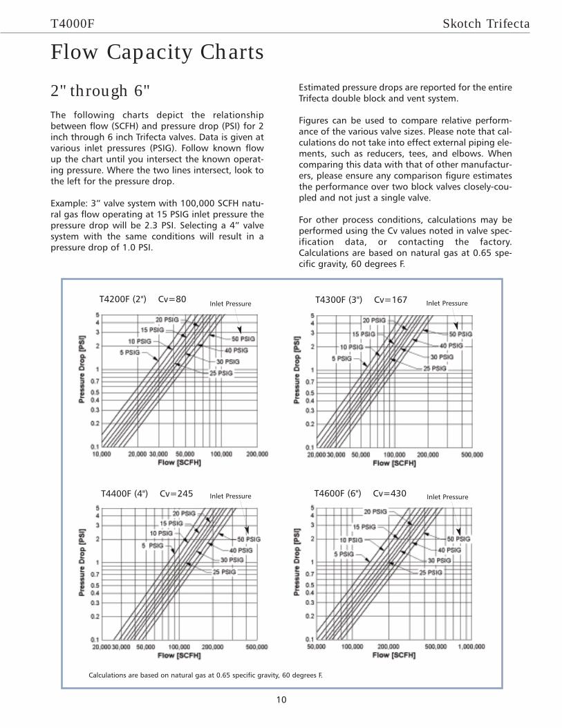
2" through 6"The following charts depict the relationshipbetween flow (SCFH) and pressure drop (PSI) for 2inch through 6 inch Trifecta valves. Data is given atvarious inlet pressures (PSIG). Follow known flowup the chart until you intersect the known operat-ing pressure. Where the two lines intersect, look tothe left for the pressure drop.
Example: 3” valve system with 100,000 SCFH natu-ral gas flow operating at 15 PSIG inlet pressure thepressure drop will be 2.3 PSI. Selecting a 4” valvesystem with the same conditions will result in apressure drop of 1.0 PSI.
Estimated pressure drops are reported for the entireTrifecta double block and vent system.
Figures can be used to compare relative perform-ance of the various valve sizes. Please note that cal-culations do not take into effect external piping ele-ments, such as reducers, tees, and elbows. Whencomparing this data with that of other manufactur-ers, please ensure any comparison figure estimatesthe performance over two block valves closely-cou-pled and not just a single valve.
For other process conditions, calculations may beperformed using the Cv values noted in valve spec-ification data, or contacting the factory.Calculations are based on natural gas at 0.65 spe-cific gravity, 60 degrees F.
Flow Capacity Charts
Inlet Pressure T4200F (2") Cv=80 T4300F (3") Cv=167
T4400F (4") Cv=245 T4600F (6") Cv=430
Inlet Pressure
Inlet Pressure Inlet Pressure
Calculations are based on natural gas at 0.65 specific gravity, 60 degrees F.
10

Skotch Trifecta T4000F
Opening1. With the block valves closed and the vent open,gas enters the inlet port and is blocked by two flow-to-close plugs (the inlet and outlet block). To posi-tively prevent fuel leakage into an idle burner, thechamber between is vented to atmosphere throughthe hollow outlet valve stem. (Figure 1)
2. Pneumatic pressure at the top of the actuatorcylinder moves the piston downward, compressingthe outlet return spring and forcing the outlet blockopen. The cage slides down over the post until themachined surfaces inside the cage come in contactfirst with a spring-energized soft seal, and thenwith a metal back-up seat, closing the vent. (Figure2)
3. With the vent closed, the system continues tostroke, pushing the inlet block open, so that gasbegins to flow. A travel stop halts valve movementafter full stroke is achieved. (Figure 3)
Closing1. To close the valve and open the vent, pilot air isexhausted from the actuator. Return springs drivethe inlet and outlet valves toward their seats.(Figure 3)
2. As the inlet valve enters its seat ring, gas flow isisolated. The inlet block moves through its over-travel until contact is made with the back-up seat tofully close the inlet valve. (Figure 2)
3. As the outlet valve continues moving toward itsseat, the cage separates from the post, opening thevent. The outlet block enters the seat ring, isolatingthe vent from downstream piping. When the outletblock contacts the metal back-up seat, the system isfully closed. (Figure 1)
Principles of OperationFigure 1
Figure 2
Figure 3
11