
Contentsglobalroofs.co.za.dedi64.cpt1.host-h.net/.../2016/... · Skorpion Mine (sulphuric acid...
37
Transcript of Contentsglobalroofs.co.za.dedi64.cpt1.host-h.net/.../2016/... · Skorpion Mine (sulphuric acid...


Contentsp1 ..................................................................about MODEK
p2 ................. benefits of natural light in building design
p4 ........................................using rooflighting for lighting
p8 ........................................using rooflighting for heating
p11 ........................rooflight configuration & construction
p14 .................... choosing the right material and colour
p18 ........................... choosing the right MODEK product
p21 ............................................. more about MODEK GRP
p24 ..................................................... more about MODEK
polycarbonate and other thermoplastics
p26 .............................non-fragile roof sheeting, walk on
p30 ..................................................................... installation
p34 .................... quick guide - comparison of materials
Modek online brochure
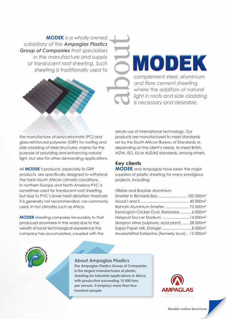
MODEK has over 20 years of experience in the manufacture of polycarbonate (PC) and glass-reinforced polyester (GRP) for roofing and side cladding of steel structures, mainly for the purpose of providing and enhancing natural light, but also for other demanding applications. All MODEK’s products, especially its GRP products, are specifically designed to withstand the harsh South African climatic conditions. In northern Europe and North America PVC is sometimes used for translucent roof sheeting, but due to PVC’s lower heat-distortion threshold it is generally not recommended, nor commonly used, in hot climates such as Africa.
MODEK sheeting compares favourably to that produced anywhere in the world due to the wealth of local technological experience the company has accumulated, coupled with the
About Ampaglas PlasticsThe Ampaglas Plastics Group of Companies is the largest manufacturers of plastic sheeting for industrial applications in Africa, with production exceeding 15 000 tons per annum. It employs more than four hundred people.
astute use of international technology. Our products are manufactured to meet standards set by the South African Bureau of Standards or, depending on the client’s needs, to meet British, ASTM, ISO, EU or AUS/NZ standards, among others.
Key clientsMODEK and Ampaglas have been the major suppliers of plastic sheeting for many prestigious projects, including:
Hillside and Bayside Aluminium Smelter in Richards Bay ........................... 100 000m²Mozal I and II............................................... 40 000m²Bahrain Aluminium Smelter ....................... 72 000m²Kensington Cricket Oval, Barbados .......... 6 000m² Nelspruit Soccer Stadium ......................... 14 000m²Skorpion Mine (sulphuric acid plant) ....... 28 000m²Sappi Paper Mill, Stanger ............................ 8 000m²ArcelorMittal Saldanha (formerly Iscor) ... 15 000m²
complement steel, aluminium and fibre cement sheeting where the addition of natural light in roofs and side cladding is necessary and desirable.
MODEK is a wholly owned subsidiary of the Ampaglas Plastics
Group of Companies that specialises in the manufacture and supply
of translucent roof sheeting. Such sheeting is traditionally used to

Modek online brochure2
There are a number of benefits to adding more daylight to any work or home environment.
Improved concentration and moodDaylight is an essential natural asset that directly influences our brain functioning and mood. In schools, research demonstrates a clear positive correlation between classrooms with good natural light and improved student performance and attendance, while limited exposure to sunlight due to the shortening of days in winter has been linked to Seasonal Affective Disorder, or SAD, a condition marked by depressive symptoms, in certain countries.
Improved salesIn addition to improving concentration and productivity in the workplace, research into retail environments suggests that natural light may also boost sales because colours seem more vivid and true, making goods appear more attractive.
Benefits of natural light in buildingdesign
Daylight is a vital natural resource that has many advantages over artificial light and heating, the key one being that it is a completely free and unlimited natural resource.
light
In summary• The benefits of using natural light in building
design can be felt on a human, environmental and economic level.
• Benefits to humans include improved mood, concentration and healing.
• Benefits to the environment are primarily reduced carbon dioxide emissions due to diminished reliance on artificial heating and lighting.
• Benefits to the economy include improved workforce productivity and sales, and reduced expenditure on energy for heating and lighting.
Better healthStudies in hospitals have proven that the recovery of patients is accelerated in areas where levels of natural light are increased.
Tax benefitsThe Tax Laws Amendment Act (Act no 17 of 2009) of South Africa allows tax breaks on income tax for businesses who demonstrate energy efficiency savings, as compared against a baseline benchmark and measured by the National Energy Efficiency Agency. Please see the section “Using rooflights to save energy” for more information on how designing for improved natural light can improve energy efficiency.
Reduction in energy costsNatural light helps reduce energy consumption by reducing both the amount of artificial light required and the energy required for heating during the winter months. Please see the section “Using rooflights to save energy” for more information.

Natural light:the natural agent that stimulates sight and makes things visible : the light of the sun
natu
ral l
ight

Modek online brochure4
The light bulb is a poor substitute for natural light when it comes to meeting our need for light. This is why, as of 2009, legislation in the United Kingdom demands that buildings be designed in such a way that at least 20% of wall area or 10% of roof area consists of light-transmitting elements in order to allow natural daylight in.
There are a number of factors to consider when deciding how much rooflighting should be installed in a given building, as well as the materials to be used for the lighting.
Building sizeThe question of whether a building should have rooflights, and if so to what percentage of the floor space they should cover, is largely determined by the size of the building.
For smaller buildings vertical glazing (windows) is generally sufficient to provide areas within six metres of the window with enough light.
For larger buildings, where there are fewer external windows relative to the building’s operational floor area, rooflighting or a combination of both rooflighting and wall glazing is needed.
If well planned, rooflighting can provide exactly the amount, type and distribution of natural light required to meet any given building’s requirements.
Building usageThe use of a given building will determine the required level of light, and whether this will be measured horizontally or vertically.
For manufacturing environments and office spaces, the tasks being illuminated are usually on a horizontal plane, so it is usually more appropriate to measure light levels horizontally.
For some applications (eg storage facilities and racking), the illumination of vertical surfaces is more relevant and light levels should then be analysed vertically.
In any given building the vertical illuminance levels are generally lower than the horizontal, although lower light levels are often more acceptable for tasks viewed vertically (such as storage facilities) than those viewed horizontally.
In summary• Rooflights are a good way to introduce natural
light for lighting purposes.• When deciding on how many rooflights to
install and what material to use, it is important to take into consideration various factors such as the size of the building, what it is used for, the type of lighting required (direct or diffuse), the brightness of light required and how that relates to heating, as well as the automation of artificial light sources.
lightingroof
Daylight has the potential to provide adequate illumination between the
hours of 8.30am and 5.30pm for most days of the year.
Using for lighting
Modek online brochure
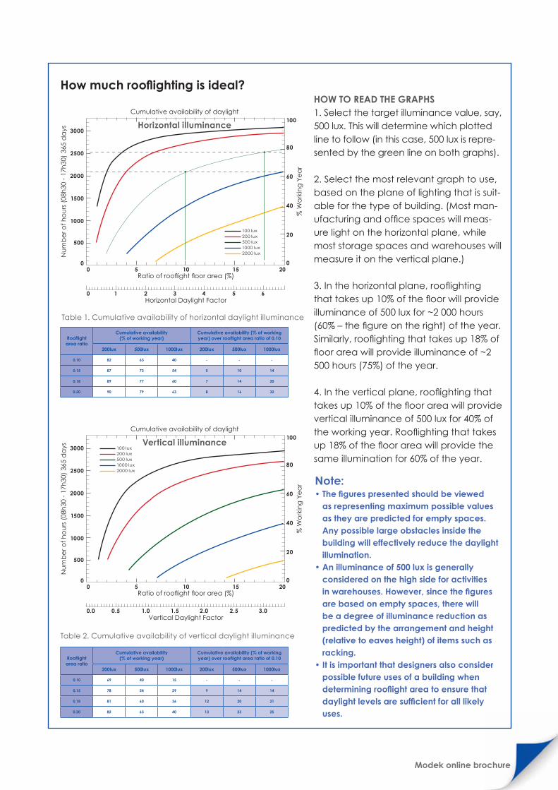
How much rooflighting is ideal?
Note: • The figures presented should be viewed
as representing maximum possible values as they are predicted for empty spaces. Any possible large obstacles inside the building will effectively reduce the daylight illumination.
• An illuminance of 500 lux is generally considered on the high side for activities in warehouses. However, since the figures are based on empty spaces, there will be a degree of illuminance reduction as predicted by the arrangement and height (relative to eaves height) of items such as racking.
• It is important that designers also consider possible future uses of a building when determining rooflight area to ensure that daylight levels are sufficient for all likely uses.
Table 2. Cumulative availability of vertical daylight illuminance
Table 1. Cumulative availability of horizontal daylight illuminance
HOW TO READ THE GRAPHS1. Select the target illuminance value, say, 500 lux. This will determine which plotted line to follow (in this case, 500 lux is repre-sented by the green line on both graphs).
2. Select the most relevant graph to use, based on the plane of lighting that is suit-able for the type of building. (Most man-ufacturing and office spaces will meas-ure light on the horizontal plane, while most storage spaces and warehouses will measure it on the vertical plane.)
3. In the horizontal plane, rooflighting that takes up 10% of the floor will provide illuminance of 500 lux for ~2 000 hours (60% – the figure on the right) of the year. Similarly, rooflighting that takes up 18% of floor area will provide illuminance of ~2 500 hours (75%) of the year.
4. In the vertical plane, rooflighting that takes up 10% of the floor area will provide vertical illuminance of 500 lux for 40% of the working year. Rooflighting that takes up 18% of the floor area will provide the same illumination for 60% of the year.
Rooflight area ratio
Cumulative availability (% of working year)
Cumulative availability (% of working year) over rooflight area ratio of 0.10
200lux 500lux 1000lux 200lux 500lux 1000lux
0.10 82 63 40 - - -
0.15 87 73 54 5 10 14
0.18 89 77 60 7 14 20
0.20 90 79 63 8 16 32
Rooflight area ratio
Cumulative availability (% of working year)
Cumulative availability (% of working year) over rooflight area ratio of 0.10
200lux 500lux 1000lux 200lux 500lux 1000lux
0.10 69 40 15 - - -
0.15 78 54 29 9 14 14
0.18 81 60 36 12 20 21
0.20 82 63 40 13 23 25
Ratio of rooflight floor area (%)0 5 10 15 20
3000
2500
2000
1500
1000
500
0
100
80
60
40
20
0
Cumulative availability of daylight
Horizontal illuminance
Nu
mb
er o
f ho
urs
(08
h30
- 1
7h30
) 36
5 d
ays
% W
ork
ing
Ye
ar
0 1 2 3 4 5 6Horizontal Daylight Factor
100 lux200 lux500 lux1000 lux2000 lux
Ratio of rooflight floor area (%)0 5 10 15 20
3000
2500
2000
1500
1000
500
0
100
80
60
40
20
0
Cumulative availability of daylight
Vertical illuminance
Nu
mb
er o
f ho
urs
(08
h30
- 1
7h30
) 36
5 d
ays
% W
ork
ing
Ye
ar
0.0 0.5 1.0 1.5 2.0 2.5 3.0Vertical Daylight Factor
100 lux200 lux500 lux1000 lux2000 lux
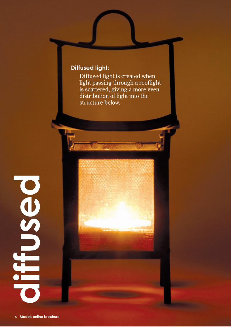
Diffused light:Diffused light is created when light passing through a rooflight is scattered, giving a more even distribution of light into the structure below.
diff
use
d
6 Modek online brochure

Type of lighting requiredRooflighting can provide two types of natural light: direct and diffused.
DIRECT LIGHT • What is it? Direct light is created when light
passes through a rooflight without any disruption or interference. It provides strong light on a focused area, but less general light in surrounding area.
• When is it used? In areas where strong light is needed on a focused area for detailed work (eg painting) or where designer wants the sky to be visible.
• What are its drawbacks? Direct light causes shadows and glare on sunnier days, and provides less general light in areas out of the direct beam.
• What materials are used? Polycarbonate, acrylic and glass in clear and most tinted options provide direct light.
DIFFUSED LIGHT • What is it? Diffused light is created when light
passing through a rooflight is scattered, giving a more even distribution of light into the structure below.
• When is it used? When the requirement is for ambient lighting over a large area with minimal shadows. Most industrial, commercial and sporting facilities prefer diffused light for these qualities.
• What are its drawbacks? Diffused lighting obscures the sky. Additional artificial light may be required on overcast days and in areas where detailed work is done.
• What materials are used? Glass-reinforced polyester (GRP) in all forms, polycarbonate, ultra high
impact (UHI) acrylic and glass in patterned and opal-tinted forms provide diffused light.
The brightness of light requiredIn some situations the amount of light entering the building needs to be controlled, usually to prevent overheating. Material thickness, diffusing or colour tints, and the number of skins used can all affect overall light transmission. For instance, in clear for-mat most single-skin rooflight materials will have a light transmission of 80% to 90%. Adding a tint or an extra skin can significantly reduce this percentage.
Automation of artificial lightIt is unlikely that buildings will be able to do without artificial lighting altogether. Artificial light will always be needed in certain parts of the working day and on days when it is overcast, especially in areas where light levels need to remain constant. But who decides when the lights should go on, and be switched off again? In workplaces where natural daylight levels are sometimes low and there is no lighting control, experience has proved that lights tend to get turned on in the morning and stay on all day, regardless of whether they are needed or not.
To reduce reliance on human intervention, artificial lighting can be automated to operate on a needs basis by using technology such as on/off photoelectric cells and proportional lighting controls. When deciding to automate artificial lighting, it is best to consult an artificial-lighting specialist who can put in place a system that will work in harmony with natural light to reduce energy consumption.
Poor distribution of light
Direct light
Good distribution of light
Diffused light
Modek online brochure
Standard MaintainedIlluminance (Lux)
Characteristics of Activity/Interior
Representatives Activities/Interiors
50 - 100Interiors used occasionally,with visual tasks confined
to movement, limitedperception of detail.
Corridors, Bulk Stores
150 - 200Continuously occupiedinteriors, visual tasks notrequiring perception or
detail
Loading Bays, PlantRooms
300 - 500 Moderately difficult visualtasks, colour judgement
may be required
Packing, General Offices,Engine Assembly, Retail
Shops
750 - 1000 Difficult visual tasks,accurate colour judgement
required.
Drawing offices, ChainStores, General Inspection,
Electronic Assembly,Supermarkets
1500 - 2000 Extremely difficult visual tasks
Precision Assembly, FabricInspection

Modek online brochure8
In the Southern Hemisphere, the best way to make use of solar gain (the heating effect of the sun) is to design the building so that windows and rooflights mostly point towards the north, while at the same time minimising the number of those that face the cooler south.
When the building also has solid walls and floors (thermal mass), which have an insulating effect, it will act as a heat store, collecting heat during the day and releasing it as the temperature drops in the evening. The result: radical reductions in the building’s total energy consumption and associated carbon-dioxide emissions.
Optimising rooflight area for heatingResearch conducted by the Institute of Energy and Sustainable Development at Leicester’s De Montfort University (DMU) has refuted the widely held view that rooflights offer poor insulation in comparison to the rest of the roof structure.
The fact is that many of a building’s characteristics – such as temperature set point, hours of occupancy and internal gains – influence its energy demand, so the effect of installing rooflighting on energy usage can vary from building to building.
Rooflighting can reduce a building’s carbon footprint by minimising heating costs in the colder months – as long as the rooflight area is calculated in such a way to avoid overheating.
heating Using
rooflighting for

Modek online brochure
That said, as a general rule rooflighting that totals up to 15% of the total floor area will always lead to energy savings, with further energy benefits to be had from up to 20% of rooflighting in certain circumstances. Specifically, the DMU work shows that:
IN BUILDINGS USED PRIMARILY DURING DAYLIGHT HOURS... • Energy savings is significant in all cases where
rooflights constitute 15% of floor area. • In areas with higher illumination, these benefits
are significantly improved by increasing the rooflight area to 20%.
• In areas with low illumination, there is no benefit to increasing the rooflight area beyond 15%.
IN BUILDINGS USED 24 HOURS A DAY...• Energy savings is significant in all cases where
rooflights constitute 15% of total floor area.• In areas with high illumination, there are minor
additional savings to be had by increasing rooflight area to 20%.
• In areas with low illumination, most of the energy savings occur where rooflighting constitutes up to 10% of the floor area. Increasing this to 15% results in minor further savings. However, increasing rooflight area even more, to 20%, actually results in a slight increase in carbon dioxide emissions.
How other heat sources determine rooflight areaCorrectly managed solar gain is a benefit that can reduce heating requirements. However, it is an SABS 204 requirement that solar gain is limited to avoid excessive internal temperature rise in summer. This can be achieved by making sure that solar gain and other internal gains – usually stemming from occupants, artificial lighting and internal processes – combined do not exceed 35 watts per square metre (W/m²). The expected internal gains of a building therefore define the maximum allowable solar gain, which in turn defines the rooflighting area (see table, based on findings by the DMU. Note that figures are based on evenly distributed light).
HEAT GAINS DUE TO FACILITY PROCESSESAny large plant or process facility will produce significant process heat gains, sometimes even in excess of the total limit of 35W/m². In such cases, localised heat extraction or cooling should be used to prevent overheating.
HEAT GAINS DUE TO ARTIFICIAL LIGHTING Internal gains due to artificial lighting can be significant. Retail outlets, for example, usually require bright lighting that can generate between 15 and 20W/m² – enough to present problems if artificial lighting is used in conjunction with rooflighting of more than 10% or 12% of floor area during times of maximum solar gain.
That said, solar gain is at its highest when daylight illuminance is also at its highest, so if the rooflight area is big enough to provide sufficient light, heat gains through artificial lighting can be
In summary• Installing rooflights can generate solar
gain (heat from the sun), which is usually a benefit in that it reduces heating requirements and associated carbon dioxide emissions.
• Assuming there are no other significant sources of internal heat, rooflight area of 15% of the floor area will always result in reduction in energy usage for heating.
• In instances where there are other significant sources of internal heat (such as facility processes, artificial lighting and occupants), rooflighting will need to be reduced so that total heating gains do not exceed 35 watts per square metre.
InternalGain
Maximum SolarGain
Equivalent Rooflight
to floor area
0 W/m² 35 W/m² 21%
5 W/m² 30 W/m² 18%
10 W/m² 25 W/m² 15%
15 W/m² 20 W/m² 12%
20 W/m² 15 W/m² 10%

Modek online brochure10
greatly reduced (or eliminated) by switching off artificial lighting.
In cases where artificial lighting will be consistently controlled – in other words, where it is done automatically rather than manually – it would be reasonable to disregard the internal gain from artificial lighting when considering rooflighting area because it would only be present when solar gain is minimal (eg at night).
HEAT GAINS DUE TO OCCUPANTSThe heat gains due to the occupants of a building depends largely on the occupant density. In large industrial or storage facilities occupant density is typically low enough to be considered insignificant, so rooflight areas of up to 21% can be used without causing overheating.
One person produces approximately 140W seated or 160W while doing light standing work or walking, rising to 265W when carrying out medium bench work. As a result, where occupant density reaches one person per 30 square metres (m2), as it does in retail shops, for example, internal gains may reach 5W/m2. At this occupant density and level of internal gain, rooflight areas of up to 18% will not cause overheating.
Where occupant densities increase further, for instance in offices or classrooms, internal gains should be checked carefully to determine
the appropriate rooflight area. Very densely occupied environments that also contain equipment – call centres, for example – can easily have cumulative internal gains of up to 30W/m2. This is too close to the total acceptable internal gain of 35W/m2 to allow for much rooflighting without then requiring the use of mechanical cooling.
ENSURING EVEN LIGHT DISTRIBUTIONThe figures quoted in the table in the previous section assume that light has been evenly distributed throughout the building. This depends on the degree of light diffusion from the rooflights, the height between roof and ceiling and the rooflight layout or distribution. The lower the ceiling, or less evenly spread the rooflights, the greater the level of diffusion required.
If rooflights are clear or do not provide enough diffusion, then the direct light can produce localised overheating directly beneath the rooflights, regardless of rooflight area, in the same way overheating can occur next to a window. This can be resolved by using a rooflight layout that spreads light as evenly possible and selecting the material thickness and colour for optimal levels of diffusion.
Please see our sections on Rooflight design and distribution and Choosing the right material and colour for more information.
Values of insertion in excess of 40W/m² are shaded blue. The assessment is clearly dependant on the level of expected internal gains. For large-span industrial buildings the usage is likely to remain constant for the lifetime of building (eg storage, retail or manufacture).
Where process-intensive manufacture is intended, the associated high-internal gains may require localised extraction to prevent overheating. This is to used as a guide only. Full assessment must be done by the professional concern.
Cumulative availability of vertical daylight illuminance
Rooflight to floor area ratio Total gain Qtot = Computed solar = internal gains (range 0 to 20W/m²)
grr 0W/m² 5W/m² 10W/m² 15W/m² 20W/m²
0.10 16.8 21.8 26.8 31.8 36.8
0.11 18.5 23.5 28.5 33.5 38.5
0.12 20.2 25.2 30.2 35.2 40.2
0.13 21.9 26.9 31.9 36.9 41.9
0.14 23.5 28.5 33.5 38.5 43.5
0.15 25.2 30.2 35.2 40.2 45.2
0.16 26.9 31.9 36.9 41.9 46.9
0.17 28.6 33.6 38.6 43.6 48.6
0.18 30.3 35.3 40.3 45.3 50.3
0.19 32.0 37.0 42.0 47.0 52.0
0.20 33.6 38.6 43.6 48.6 53.6

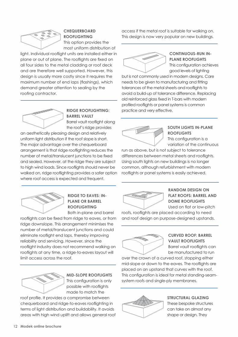
Rooflight configurationThe factors to consider when designing the rooflight configuration are: • Whether there is enough general lighting
to create a pleasant and suitable internal environment.
• Whether there is a need for increased or controlled light levels in specific areas of the building (such as the play area in a sports hall).
• The relationship between the roof height and the diffusing quality of the rooflights to provide good general light at ground level.
• The degree of roof maintenance and roof access envisaged.
• Weatherability and minimising overlaps, especially between dissimilar materials.
There are a number of possible configurations for rooflights.
In summary• Rooflight configuration refers to the positioning
of the rooflight in the roof and is influenced by a range of factors such as budget, lighting needs, roof pitch, the need for roof access, wind exposure and the existing building design.
• Rooflight construction refers to the methods used to assemble the rooflight relative to the roof structure. The construction method used is heavily influenced by the configuration chosen for the rooflighting.
Modek online brochure
Rooflight configuration construction
Rooflighting should be configured and constructed so as to maximise light and heating benefits for a given building, as influenced by other factors
like budget, roof access, building usage and alternative heat sources.
Modek online brochure12
CHEQUERBOARD ROOFLIGHTINGThis option provides the most uniform distribution of
light. Individual rooflight units are installed either in plane or out of plane. The rooflights are fixed on all four sides to the metal cladding or roof deck and are therefore well supported. However, this design is usually more costly since it requires the maximum number of end laps (flashings), which demand greater attention to sealing by the roofing contractor.
RIDGE ROOFLIGHTING: BARREL VAULT Barrel vault rooflight along the roof’s ridge provides
an aesthetically pleasing design and relatively uniform light distribution if the roof slope is short. The major advantage over the chequerboard arrangement is that ridge rooflighting reduces the number of metal/translucent junctions to be fixed and sealed. However, at the ridge they are subject to high wind loads. Since rooflights should never be walked on, ridge rooflighting provides a safer option where roof access is expected and frequent.
RIDGE TO EAVES: IN-PLANE OR BARREL ROOFLIGHTINGBoth in-plane and barrel
rooflights can be fixed from ridge to eaves, or from ridge downslope. This arrangement minimises the number of metal/translucent junctions and could eliminate rooflight end laps, thereby improving reliability and servicing. However, since the rooflight industry does not recommend walking on rooflights at any time, a ridge-to-eaves layout will limit access across the roof.
MID-SLOPE ROOFLIGHTS This configuration is only possible with rooflights made to match the
roof profile. It provides a compromise between chequerboard and ridge-to-eaves rooflighting in terms of light distribution and buildability. It avoids areas with high wind uplift and allows general roof
access if the metal roof is suitable for walking on. This design is now very popular on new buildings.
CONTINUOUS-RUN IN-PLANE ROOFLIGHTSThis configuration achieves good levels of lighting
but is not commonly used in modern designs. Care needs to be given to manufacturing and fitting tolerances of the metal sheets and rooflights to avoid a build-up of tolerance difference. Replacing old reinforced glass fixed in T-bars with modern profiled rooflights or panel systems is common practice and very effective.
SOUTH LIGHTS IN-PLANE ROOFLIGHTSThis configuration is a variation of the continuous
run as above, but is not subject to tolerance differences between metal sheets and rooflights. Using south lights on new buildings is no longer common, although refurbishment with modern rooflights or panel systems is easily achieved.
RANDOM DESIGN ON FLAT ROOFS: BARREL AND DOME ROOFLIGHTSUsed on flat or low-pitch
roofs, rooflights are placed according to need and roof design on purpose-designed upstands.
CURVED ROOF: BARREL VAULT ROOFLIGHTSBarrel vault rooflights can be manufactured to run
over the crown of a curved roof, stopping either mid-slope or down to the eaves. The rooflights are placed on an upstand that curves with the roof. This configuration is ideal for metal standing-seam-system roofs and single-ply membranes.
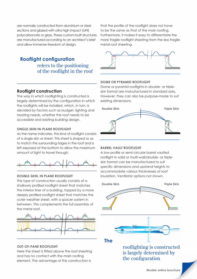
STRUCTURAL GLAZINGThese bespoke structures can take on almost any shape or design. They
Modek online brochure
are normally constructed from aluminium or steel sections and glazed with ultra high impact (UHI) polycarbonate or glass. These custom-built structures are manufactured according to an architect’s brief and allow immense freedom of design.
Rooflight constructionThe way in which rooflighting is constructed is largely determined by the configuration in which the rooflights will be installed, which, in turn, is decided by factors such as budget, lighting and heating needs, whether the roof needs to be accessible and existing building design.
SINGLE-SKIN IN-PLANE ROOFLIGHTAs the name indicates, this kind of rooflight consists of a single skin or sheet. This sheet is shaped so as to match the surrounding ridges in the roof and is left exposed at the bottom to allow the maximum amount of light to travel through.
DOUBLE-SKIN, IN PLANE ROOFLIGHT This type of construction usually consists of a shallowly profiled rooflight sheet that matches the interior liner of a building, topped by a more deeply profiled rooflight sheet that matches the outer weather sheet, with a spacer system in between. This complements the full assembly of the metal roof.
OUT-OF-PANE ROOFLIGHTHere the sheet is fitted above the roof sheeting and has no contact with the main roofing element. The advantage of this construction is
that the profile of the rooflight does not have to be the same as that of the main roofing. Furthermore, it makes it easy to differentiate the more fragile rooflight sheeting from the less fragile metal roof sheeting.
DOME OR PYRAMID ROOFLIGHT Dome or pyramid rooflights in double- or triple-skin format are manufactured in standard sizes. However, they can also be purpose-made to suit existing dimensions.
BARREL VAULT ROOFLIGHT A low-profile or semi-circular barrel vaulted rooflight in solid or multi-wall/double- or triple-skin format can be manufactured to suit specific dimensions and upstand heights to accommodate various thicknesses of roof insulation. Ventilator options not shown.
The way in whichrooflighting is constructed is largely determined by the configuration
Rooflight configurationrefers to the positioning of the rooflight in the roof
Double Skin Triple Skin
Double Skin Triple Skin

Modek online brochure14
Modek online brochure
Choosing the right materialThe most widely used rooflight materials are glass-reinforced polyester (GRP, or fibreglass), safety glass, polycarbonate (PC) and, to a lesser extent, PVC.
SAFETY GLASS Glass has excellent fire properties, good impact performance, very high light transmission and provides the benchmark against which the optical clarity of all other glazing media is commonly compared. It is widely acknowledged as having a very long life span with no discolouration from UV degradation, and laminated versions provide a good level of reduction in UV transmission.
Glass is often used for atria in shopping centres and flat, glazed rooflights are currently in fashion, although glass can also be curved for use in barrel vault rooflights or supplied with various coatings, interlayers and surface treatments to provide coloured or textured surfaces that offer diffused glazing, solar control and total UV protection to areas beneath the glazing.
GLASS-REINFORCED POLYESTER (GRP) Also known as fibreglass, GRP remains the most versatile and commonly used profiled glazing material.
GRP offers excellent performance properties and provides high levels of diffused light. In most industrial, sporting and commercial situations,
diffused light, which minimises glare and distracting shadows, is preferable.
GRP is produced to match almost all roofing profiles and is ideal for barrel vault design. MODEK high-quality GRP sheets incorporate UV-absorbing surface protection that can virtually eliminate long-term discolouration. In a budget-conscious world, GRP is a very cost-effective rooflighting material.
For more information on GRP see More about MODEK GRP.
POLYCARBONATE (PC) AND OTHER THERMOPLASTICSPolycarbonate is a clear thermoplastic formed under heat and fixed in shape by cooling. It can be recycled by reheating it to a liquid state. When correctly processed and handled, it can provide excellent impact resistance and good resistance to UV and weathering.
Other thermoplastics include PVC, which is largely used in DIY and agricultural markets, but rarely in industrial or commercial applications due to its fragility.
Acrylic has good UV resistance and is used in the manufacture of barrel vaults, modular domes and pyramids, although it is limited when it comes to impact strength and fire resistance.
For more information on polycarbonate (PC), see More about MODEK PC.
Choosing the right material and
Rooflighting material must allow light through; satisfy all durability, thermal, safety and fire requirements; and work well with the roof material and/or the glazing system being used.

Modek online brochure16
Choosing the right colourThe colour/tint chosen for rooflighting can be used to minimise solar heating.
More than 70% of the heating effect of the sun is carried by light that falls between 350 and 800 nanometres – generally, the visible light spectrum.
By changing the wavelengths of light that are transmitted through a material – in other words, by changing the colour of the material – one can effectively alter the levels of solar gain to avoid overheating.
In summary• Two materials
are most commonly used for rooflighting are glass-reinforced polyester (GRP) and polycarbonate (PC), each with their own strengths and weaknesses.
• Choosing the right colour/tint of rooflighting material can help minimise solar gain and so prevent overheating.
These diagrams depict the transmission of light at various wavelengths (colours) for clear sheets of GRP and polycarbonate. The graphs show that more than 80% of visible shortwave radiation
is transmitted through GRP and PC sheets, while harmful UV rays are blocked.Visible shortwave radiation that is transmitted into a building or room is then absorbed by
surfaces inside, turning these surfaces into heat radiators. However, the heat emitted from these “radiators” is long-wave radiation, which is not so readily transmitted through the sheet again.
The result: trapped heat builds up in the room in what is known as the greenhouse effect.
Glass Fibre Sheeting (GRP)
400 800 1200 1600 2000 2400
100
80
60
40
20
Wave length (Nanometres)
Ultraviolet Visible Infra red
Wa
ve le
ng
th t
ran
smiss
ion
%
Polycarbonate Sheeting
400 800 1200 1600 2000 2400
100
80
60
40
20
Wave length (Nanometres)
Ultraviolet Visible Infra red
Wa
ve le
ng
th t
ran
smiss
ion
%

Modek online brochure
Polycarbonate Sheeting
Glass Fibre Sheeting (GRP)
An effective method of combating heat build-up through the greenhouse effect is to have
good through ventilation and to use tinted roof sheeting, as outlined in the tables below.
The figures used in the tables are based on ColorQUEST Colorimeter testing. Shading coefficients are used for comparing solar heat transmission properties of different
glazing materials to that of clear float glass 3mm to 4mm thick, the glass being given a value of 1. To be used for comparative purposes only.
Roof Shet Tint Clear Blue Green Opal 50
Visible Spectrum (380mm - 700m)
% Light Transmission 85 40 50 50
% Light Reflectance 15 8 10 48
Solar Energy (350mm - 2100mm)
% Rejected 16 40 34 42
% Direct Transmission 83 47 57 57
% Direct Reflectance 12 7 8 39
% Absorption 5 46 35 4
% Total Transmission 84 60 66 58
Shading Coefficient 0.97 0.69 0.76 0.67
Roof Shet Tint Clear Blue Green Opal 50 Bronze Opal 10 Heat Stop
Visible Spectrum (380mm - 700m)
% Light Transmission 90 65 40 50 40 25 22
% Light Reflectance 13 10 10 42 8 74 32
Solar Energy (350mm - 2100mm)
% Rejected 13 26 41 41 40 67 60
% Direct Transmission 87 68 47 57 47 31 27
% Direct Reflectance 11 8 8 31 7 63 27
% Absorption 3 24 44 9 46 7 46
% Total Transmission 88 74 59 59 60 33 40
Shading Coefficient 1 0.86 0.68 0.68 0.69 0.37 0.46

Modek online brochure18
Domestic householdMODEK recommends the use of glass-reinforced polyester (GRP) or polycarbonate sheeting for domestic applications such as roofing, carports, sun patios and garden sheds.
Light industrial and warehousingMODEK recommends the use of glass-reinforced polyester (GRP) or polycarbonate sheeting for light industrial and warehousing applications such as roofing and rooflighting.
Material and mass Purlin spacings Weather conditions Lifespan
GRP 1.8kg/m2 1 500mm Adverse 10–15 years
GRP 2.4kg/m2 1 800mm Hostile 15–25 years
Polycarbonate 1.0mm 1 000mm Moderate 10–15 years
Polycarbonate 1.20mm 1 500mm Adverse 12–15 years
Heavy-duty GRP (non-fragile roofing) 2 100mm Cyclone 20–30 years
Material and mass Purlin spacings Weather conditions Lifespan
GRP 1.1kg/m2 900mm Moderate 5–7 years
GRP 1.4kg/m2 1 000mm Moderate 10–15 years
Polycarbonate 0.8mm 900mm Moderate 7–10 years
Polycarbonate 1.0mm 1 000mm Moderate 10–12 years
MODEK manufactures a wide range of rooflighting systems that are
suitable for any type of building, be it a home, a warehouse, a commercial
building or a sporting facility.
MODEK product
Choosing the right
Material and mass Purlin spacings Weather conditions Life span
GRP 2.4kg/m2 1 800mm Hostile 15–25 years
Polycarbonate 1.20mm 1 500mm Adverse 12–15 years
Heavy-duty GRP (non-fragile roofing) 2 100mm Cyclone 20–30 years
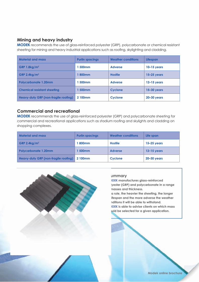
Mining and heavy industryMODEK recommends the use of glass-reinforced polyester (GRP), polycarbonate or chemical resistant sheeting for mining and heavy industrial applications such as roofing, skylighting and cladding.
Commercial and recreational MODEK recommends the use of glass-reinforced polyester (GRP) and polycarbonate sheeting for commercial and recreational applications such as stadium roofing and skylights and cladding on shopping complexes.
Material and mass Purlin spacings Weather conditions Lifespan
GRP 1.8kg/m2 1 500mm Adverse 10–15 years
GRP 2.4kg/m2 1 800mm Hostile 15–25 years
Polycarbonate 1.20mm 1 500mm Adverse 12–15 years
Chemical resistant sheeting 1 500mm Cyclone 15–30 years
Heavy-duty GRP (non-fragile roofing) 2 100mm Cyclone 20–30 years
In summary• MODEK manufactures glass-reinforced
polyester (GRP) and polycarbonate in a range of masses and thickness.
• As a rule, the heavier the sheeting, the longer its lifespan and the more adverse the weather conditions it will be able to withstand.
• MODEK is able to advise clients on which mass should be selected for a given application.
Modek online brochure

MODEK GRP it is a very tough & durable material
that in opaque format is used for yacht hulls, aircraft nose cones & mine-sweeper hulls
MO
DEK
GRP
20 Modek online brochure

Modek online brochure
Glass-reinforced polyester (GRP) was first manufactured in South Africa in 1959. It is a very tough and durable material that in opaque format is used for yacht hulls, aircraft nose cones and mine-sweeper hulls.
Benefits of choosing MODEK GRPMODEK GRP is highly scratch resistant and therefore easily handled on site.
GRP is a very durable material and some rooflights over 40 years old are still in service. Good-quality GRP rooflights are a uniquely attractive rooflighting product. They are highly resistant to degradation by the elements, do not rust or corrode, are unaffected by most aggressive chemicals and have a low coefficient of thermal expansion compared to other plastics, making them less subject to cracking problems at the fixing points.
Long-term performance is dependant on the quality and thickness of the sheet and quality of the surface protection. The durability of GRP rooflights manufactured by MODEK ensures the strength of the sheet will be retained in the long term. However, impact resistance is also heavily dependant on other factors, for example method and condition of fixings, and any deterioration of the installation can jeopardise the roof's integrity. Even when there is no deterioration of the rooflight sheet itself. (Please see Safety in Rooflights for more information.)
MODEK GRP
As with almost all plastics, GRP is adversely affected by UV rays over time due to photo degradation. In photo degradation, aggressive shortwave UV rays are absorbed by the polyester resin, where they “excite” the molecular bonds of the polymers, causing them to separate and resulting in a yellowing of the sheet.
MODEK’s GRP sheeting is manufactured using UV-stabilised unsaturated polyester resin and glass-fibre reinforcement material, which is then chemically bonded to a highly UV-stable gel coat layer on the weathering surface using a technique developed in the US and licensed to MODEK.
As a result, MODEK GRP sheeting is more resistant to weather, UV, chemicals, corrosion and surface abrasion than sheeting manufactured using more conventional methods of surface protection. It also does not transmit UV rays, which has the benefit of protecting furnishings, materials and people from harmful UV radiation. Testing has proven that the non-peel, high-gloss gel coat layer prevents fibres from becoming exposed during the normal lifespan of the sheet. Indeed, under normal conditions, a MODEK GRP gel coated sheet will remain structurally sound for more than 20 years.
All MODEK GRP products are designed to withstand harsh South African climatic conditions and gel coated products meet the following standards: SABS, BS, ASTM, ISD, EU, AUS/NZ.
Mor
e
abou
tGlass-reinforced polyester (GRP) is a translucent thermoset material under the general heading of plastic that, once formed into the required shape, can never be reshaped after curing. MODEK manufactures GRP using an automated continuous-line laminating machine that ensures consistently high product quality in successive consignments and allows for any transportable length of sheet to be made.

Modek online brochure22
Choosing the right MODEK GRP productMODEK’s GRP products can be selected along a range of criteria, depending on the requirements of the application in question.
COLOUR AND CLARITYMore than 70% of the heating effect of the sun is carried by light that falls between 350 and 800 nanometres – generally, the visible light spectrum. By changing the wavelengths of light that are transmitted through a material – in other words, by changing the colour of the material – one can effectively alter the levels of solar gain to avoid overheating.
MODEK GRP comes in a range of standard colours: clear, white (opal 50), green and blue. Certain domestic products are also manufactured in grey, bronze and Ice.
In addition to coming in a range of colours, MODEK GRP sheeting can be either clear (which creates direct lighting) or slightly opaque (for diffuse light). The diffusion is achieved through the inclusion of randomly dispersed fibreglass reinforcement material in the sheet. Diffuse light is often desirable in applications where even lighting and controlled heating is required.
Please see Choosing the right material and colour and Using rooflighting for heating for more information.
PROFILEMODEK can manufacture GRP sheeting to match all profile shapes generally used for non-translucent roofing and cladding, to any transportable length.
WEIGHTGRP sheeting is classified according to its mass rather than its nominal thickness, as thickness can vary from profile to profile even when the same product weight is used. All continuous-line laminating plants in the world manufacture to a mass parameter, not thickness, expressed as a nominal weight per surface area. In South Africa the metric unit used is kilograms per square metre of product (kg/m2).
MODEK manufactures GRP in the following standard weights: • 1.1kg/m2
• 1.4kg/m2
• 1.8kg/m2
• 2.4kg/m2
• 3.0kg/m2
• 3.6kg/m2
• walk on
Other weights can be manufactured to specification depending on particular requirements. Please see Choosing the right MODEK product to see which mass is best suited to a given application, or contact MODEK’S Technical Department for advice.
Dimensional tolerances The following extract from SABS 1150/1984 describes the dimensional tolerances applicable to MODEK GRP sheets.• General The nominal dimensions of a sheet shall
be as specified by the purchaser. • Length The actual length of a sheet shall be at
least equal to the nominal length, and shall not exceed it by more than 20mm.
• Width The actual width of a sheet shall be at least equal to the nominal width, and shall not exceed it by more than 15mm.
• Rectangularity Any deviation from squareness shall not exceed 10mm.
• Edge trueness Any departure of any edge of the sheet from a straight line shall not exceed 15 mm.
In summary• MODEK GRP is scratch-resistant, making
it easy to handle on site, and UV resistant, to protect people and interiors from harmful UV rays
• When choosing MODEK GRP, you will need to specify colour, clarity/opacity, profile and weight required
• MODEK’s technical department can help you choose the right GRP product for a given application

Modek online brochure
Colour and Clarity:by changing the colour of the material – one can effectively alter the levels of solar gain to avoid overheating.
colo
ur a
nd c
larit
y

Modek online brochure24
Polycarbonate is one of the newer plastics to be used in the construction industry around the world. MODEK has been closely involved with the manufacture and distribution of profiled polycarbonate roof sheeting in South Africa for the past 15 years. We use the highest-grade polycarbonate polymer available and modern co-extrusion technology, ensuring a high-product quality and allowing for any transportable length of sheet to be made.
Benefits of choosing MODEK polycarbonatePolycarbonate offers exceptional impact resistance, high levels of light transmission, good workability and good fire rating.
MODEK polycarbonate sheeting is resistant to chemical attack and corrosion in most industrial and marine environments. Tests have found the following:• MODEK polycarbonate is highly resistant to
corrosion and high concentrations of mineral acids, many organic acids, oxidising and reducing agents, neutral and acid salt solutions, many oils and fats, saturated aliphatic and cyclo-aliphatic hydrocarbons and alcohols.
• MODEK polycarbonate is not resistant to strong acids and alkalis, methyl alcohol, aromatic hydrocarbons and chlorinated hydrocarbons nor to lengthy immersion in hot water.
• MODEK polycarbonate must not be used in conjunction with plasticised PVC. This will result in stress corrosion cracking and cause damage to the MODEK PC sheet.
• MODEK polycarbonate sheets are ideal for coastal applications.
As with almost all plastics, polycarbonate is adversely affected by UV rays over time due to photo degradation. In photo degradation, aggressive shortwave UV rays are absorbed by the polyester resin, where they “excite” the molecular bonds of the polymers, causing them to separate and resulting in a yellowing of the sheet.
MODEK’s polycarbonate sheeting is manufactured using a layer of highly UV stabilised Polycarbonate is co-extruded on the weathering side of all MODEK Polycarbonate roof sheets. This layer will not crack or delaminate, and ensures years of clear performance in the harsh South African climate. This UV layer eliminates up to 99% of UV radiation transmitted through the sheet, so protecting materials and people beneath it. This layer will not crack or delaminate, and ensures years of clear performance in the harsh South African climate.
Choosing the right MODEK polycarbonate productMODEK’s polycarbonate products can be selected along a range of criteria, depending on the requirements of the application in question.
COLOUR AND CLARITYMore than 70% of the heating effect of the sun is carried between 350 and 800 nanometres (generally, the visible light spectrum). More than 85% of these wavelengths are transmitted through a clear polycarbonate sheet. It is possible to vary levels of light transmission, and therefore the amount of heat that is transmitted, by changing the colour of the polycarbonate sheeting or by choosing a more opaque, diffusing sheet.
MODEK polycarbonate and other thermoplasticsM
ore
ab
out
Polycarbonate is a versatile material used extensively as a rooflight glazing. It is very resistant to impact, transmits high levels of light, is relatively easy to use and it has a good fire rating.

Modek online brochure
It is commonly available in clear and tinted options, with clear and most tints providing direct light, while clear patterned and opal tint provides diffused light and gives a soft quality to the light. The standard colours available are clear, white (opal 50) and bronze. Silver (Heat Stop), blue and green are also available subject to order quantity.
MODEK has introduce an new range of Poly-carbonate Diffuser profile material. These sheeting are design to increase visible light in the building and to reduce solar gain and internal, hot spots. All profiles are manufactured using this material.
Please see Using rooflighting for heating for more information.
SHEET FORMPolycarbonate (PC) comes in two sheet forms, each with its own particular characteristics and properties: Solid (flat or domed), Profiled.
Solid (flat or domed) polycarbonate offers good optical clarity and superb workability. It can be cold-curved on site, is suitable for use with a variety of glazing bar systems, and can be moulded into various shapes such as domes and pyramids.
Profiled polycarbonate matches profiled roof cladding and allows the sky to be viewed through a corrugated material, a feature popular with many designers. MODEK polycarbonate comes in all the profile shapes generally used for non-translucent roofing and cladding in South Africa.
That said, extrusion and vacuum-forming techniques allow a huge variety of profiles to be produced. As a result MODEK can manufacture new or additional roofing profiles, although it should be noted that the time and cost incurred is likely to be considerable.
Nominal thicknessBecause of the inherent variances of tolerance experienced when profiling a thermoplastic extrusion, the actual thickness of a sheet varies slightly from one point to another. As a result, the internationally accepted unit of measurement for polycarbonate sheeting is the nominal thickness of the sheet, established by representative
measurements (taken be vernier or micrometer) at various points across the full width of the sheet.
MODEK manufactures three nominal thickness specifications: 0.8mm, 1.00mm and 1.25mm. A layer of UV protection PC is co-extruded on the weathering side of all MODEK polycarbonate roof sheets.
0.8mm nominal thickness is manufactured as a lightweight polycarbonate sheet to be used mainly in lighter, domestic applications and applications where exposure to wind is minimal and spanning requirements are less than normal. The 0.8mm nominal thickness products are restricted to certain profiles only.
1.20mm nominal thickness is the standard weight specification for all industrial installations. This specification will meet the rigorous conditions found in an industrial environment, particularly that of deflection under load (positive and negative), handling on-site, spanning capabilities and general robustness of profile.
Other thermoplastics PVC was used for industrial rooflight applications in the 1970s and 1980s, but has poorer impact resistance and weathering performance than other alternatives. PVC will not meet the non-fragility requirements without the addition of extra safety measures in the rooflight construction. It is now used very rarely in industrial or commercial applications, although it is popular DIY material in the USA. It is not expensive, has a reasonable strength-to-weight ratio and is straightforward to work with, thereby deserving its success as a DIY material for small, low-rise domestic projects.
In summary• MODEK polycarbonate is a robust, UV-blocking
material that is well suited to most domestic and industrial applications
• When choosing MODEK polycarbonate, you will need to specify colour, clarity/opacity, sheet form and/or profile, and nominal thickness required
• MODEK’s technical department can help you choose the right polycarbonate product for a given application
de
sig
n fo
r sa
fety
26 Modek online brochure
Modek online brochure
As with all building, work good safety standards are essential to prevent accidents. In accordance with the Health and Safety Act and South Africa National Standards (SANS) regulations, the building should be designed with safety in mind, not only for the construction period but throughout the normal life of the building. This must include considering the safety of people involved in maintenance, repair and even demolition. It might mean providing permanent access to the roof, walkways and parapets, for example.
Designing to improve rooflighting safetyWhere specifying rooflights, designers should consider the following options:• Choosing in-plane rooflights that are non-fragile. • Making sure that all in-plane units (even non-
fragile ones) are easily identifiable when installed, for example by the use of bright red fixing heads, to identify the rooflight location.
• Fitting rooflights designed to project above the plane of the roof that cannot be walked on (these reduce risk, but should still be capable of withstanding a person falling onto them).
• Protecting rooflight openings, for example by means of mesh or grids fitted below the rooflight or between the layers of a built-up rooflight. PVC, which is an inherently brittle material, always requires extra safety reinforcement.
• Increasing the safety margin when selecting rooflighting materials and other components (see “Why increase the safety margin?”)
The designer and building owner should also design the roof to accommodate ongoing maintenance and roof access during the rooflight’s lifespan. As a guide (please see section on non-fragility ratings under the GRP walk on section for more information on Class A, B and C classifications mentioned below):• Low-maintenance roofs require maintenance
that is either very infrequent and so requires very infrequent access by experienced roofworkers only, or can be done from ladders. For these roofs the minimum non-fragility classification is Class C.
• Medium-maintenance roofs are those that require regular access for maintenance by experienced roof workers only. For these roofs the minimum non-fragility classification is Class A or B.
• High-maintenance roofs are those that require frequent access for maintenance by people who may not be experienced roofworkers (eg for plant exhausts). For these roofs the minimum non-fragility classification is Class B, with dedicated walkways to reach the plant to be maintained.
Designers should adopt a principle of matching the non-fragile classification of the roof and rooflight assemblies while following the above guidelines to eliminate areas of unequal performance from the roof covering.
It is the responsibility of the designer to determine the risks, the required period of non-fragility and the safety margins requires, and then to adapt the building design accordingly.
Many rooflights and metal lining panels are considered to be fragile relative to metal roof sheeting, a fact that building designers and contractors should take into account for safety reasons when designing access routes for ongoing maintenance of a building, planning a building project, selecting rooflighting material and installing rooflighting.
Non fragile roof sheeting,
walk-on

Modek online brochure28
Building to improve rooflighting safetyConstruction of the roof is one of the most hazardous operations because of the potential for falls or material dropping onto people below. A roofing contractor should plan and document a safe system of work before starting construction. This plan must take into account the fragility of cladding and rooflighting systems. While fully fixed metal sheeting is generally regarded as non-fragile, many rooflights and metal lining panels must be treated with greater care.
It is important to remember that even non-fragile rooflights are likely to be damaged by impact. They are usually not intended to support heavy foot traffic, and crawling boards should be used when going over them cannot be avoided, either during construction or while undergoing maintenance.
Improved rooflighting safety after constructionOn completion of a building, designers should provide a Health and Safety File to the building owner containing the following information with regard to rooflights:• The rooflight specification, including the weight
(thickness) of the rooflights, the non-fragile test method and classification when new (see Non-
fragility classification of GRP, below), and the expected non-fragile life of the roof and rooflights.
• A schedule for cleaning and maintenance for both performance and longevity of the specific rooflights.
The file should also contain the following warnings:• Avoid walking on rooflights, irrespective of their
non-fragility classification. Even rooflights that are designed to be non-fragile for the life of the roof could be damaged by foot traffic, and this may affect both the non-fragility performance and the light-transmitting quality of the rooflight in the long term.
• No person should have access to the roof, unless under the direct supervision of a competent person who is to assess risks and take action to minimise them.
• Access to the roof should be avoided in wet or in slippery conditions.
Non-fragility classification of GRPNON-FRAGILITY WHEN NEWIn terms of the guidelines set out by the NARM (British) Red Book (ACR[M]001:2005), non-fragility can be classified into three groups: Group A, Group B or Group C.
Why increase the safety margin?The safety margin of minimum-weight rooflights is sufficient to ensure they will achieve non-fragility classification when new, but will not allow for any deterioration of other aspects of the installation.
MODEK’s GRP rooflights have a service life in excess of 25 years. However, their resistance to impact relies on how well they were installed. Even if there is little degradation of the rooflight sheeting itself, long-term non-fragility could be affected by external factors such as:
• Poor design and specification • Incorrect initial installation• Corrosion of the fasteners or degradation of
supporting material • Fasteners that have worked loose or seals that
have hardened or perished• Corrosion of surrounding metal sheeting • Chafing around the fixings (which can be
accelerated by failure to install additional fixings around areas of high wind load)
• Foot traffic
Non-fragility can only be maintained if inspection and maintenance eliminates the effect of these factors. However, MODEK has established that typical maintenance procedures are usually not sufficient to achieve this.
To improve safety in the long term, MODEK recommends selecting rooflight sheeting (and other components, such as fixings) of a higher safety grade in order to increase the safety margin, so reducing dependence on installation and maintenance methods. An incremental increase in the weight of rooflight sheeting (for instance, from 2.4kg/m2 to 3.0kg/m2) will effectively increase the margin of safety and so ensure that long-term non-fragility is preserved with typical maintenance regimes.
Modek online brochure
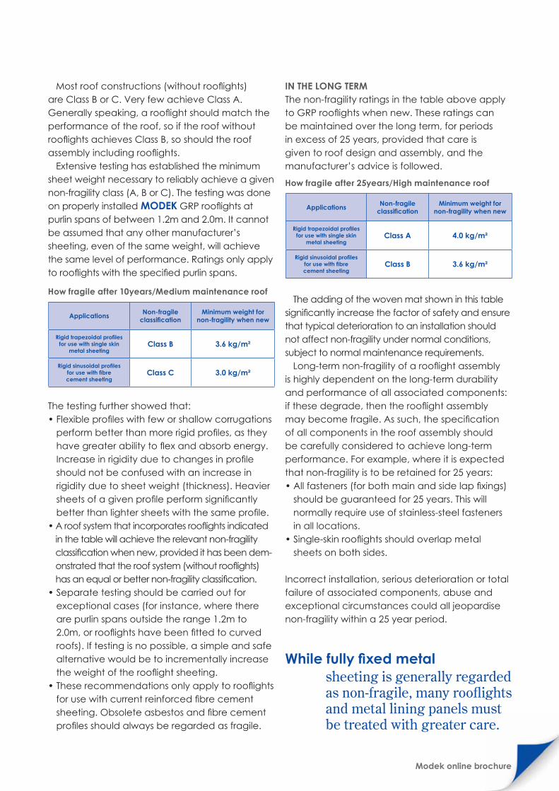
Most roof constructions (without rooflights) are Class B or C. Very few achieve Class A. Generally speaking, a rooflight should match the performance of the roof, so if the roof without rooflights achieves Class B, so should the roof assembly including rooflights.
Extensive testing has established the minimum sheet weight necessary to reliably achieve a given non-fragility class (A, B or C). The testing was done on properly installed MODEK GRP rooflights at purlin spans of between 1.2m and 2.0m. It cannot be assumed that any other manufacturer’s sheeting, even of the same weight, will achieve the same level of performance. Ratings only apply to rooflights with the specified purlin spans.
The testing further showed that: • Flexible profiles with few or shallow corrugations
perform better than more rigid profiles, as they have greater ability to flex and absorb energy. Increase in rigidity due to changes in profile should not be confused with an increase in rigidity due to sheet weight (thickness). Heavier sheets of a given profile perform significantly better than lighter sheets with the same profile.
• A roof system that incorporates rooflights indicated in the table will achieve the relevant non-fragility classification when new, provided it has been dem-onstrated that the roof system (without rooflights) has an equal or better non-fragility classification.
• Separate testing should be carried out for exceptional cases (for instance, where there are purlin spans outside the range 1.2m to 2.0m, or rooflights have been fitted to curved roofs). If testing is no possible, a simple and safe alternative would be to incrementally increase the weight of the rooflight sheeting.
• These recommendations only apply to rooflights for use with current reinforced fibre cement sheeting. Obsolete asbestos and fibre cement profiles should always be regarded as fragile.
IN THE LONG TERMThe non-fragility ratings in the table above apply to GRP rooflights when new. These ratings can be maintained over the long term, for periods in excess of 25 years, provided that care is given to roof design and assembly, and the manufacturer’s advice is followed.
The adding of the woven mat shown in this table significantly increase the factor of safety and ensure that typical deterioration to an installation should not affect non-fragility under normal conditions, subject to normal maintenance requirements.
Long-term non-fragility of a rooflight assembly is highly dependent on the long-term durability and performance of all associated components: if these degrade, then the rooflight assembly may become fragile. As such, the specification of all components in the roof assembly should be carefully considered to achieve long-term performance. For example, where it is expected that non-fragility is to be retained for 25 years:• All fasteners (for both main and side lap fixings)
should be guaranteed for 25 years. This will normally require use of stainless-steel fasteners in all locations.
• Single-skin rooflights should overlap metal sheets on both sides.
Incorrect installation, serious deterioration or total failure of associated components, abuse and exceptional circumstances could all jeopardise non-fragility within a 25 year period.
While fully fixed metal sheeting is generally regarded as non-fragile, many rooflights and metal lining panels must be treated with greater care.
How fragile after 25years/High maintenance roof
Applications Non-fragile classification
Minimum weight for non-fragility when new
Rigid trapezoidal profiles for use with single skin
metal sheetingClass A 4.0 kg/m²
Rigid sinusoidal profiles for use with fibre cement sheeting
Class B 3.6 kg/m²
How fragile after 10years/Medium maintenance roof
Applications Non-fragile classification
Minimum weight for non-fragility when new
Rigid trapezoidal profiles for use with single skin
metal sheetingClass B 3.6 kg/m²
Rigid sinusoidal profiles for use with fibre cement sheeting
Class C 3.0 kg/m²

Modek online brochure30
This is normally related to the following aspects of the installation:• Purlin or girt spacings• Diameter of fastening washer• Frequency and accuracy of fastenings
Fixing configurationsIt is not practical to give standard purlin spacings and fastening specifications for all applications, but as a guide, the following recommendations will apply to most standard installations:
For side cladding with all profiles, the maximum girt spacing should be 1 500 mm.
• The term chequerboard refers to MODEK sheets laid where the side and end laps of each sheet are fixed to, and supported by, an adjacent metal or FC sheet.
• The term continuous run refers to sheets laid in a pattern where they are fixed side-by-side to one-another, or in a verge to verge configuration.
Fixing detailsROOF PITCH < 10°:• All MODEK sheets are to be fastened to supports
through each crown of the profile (primary fixings), and side stitched to adjacent sheet not exceeding 400 mm (secondary fixings).
ROOF PITCH > 10°:• All MODEK sheets can be fastened to supports
in the trough of the profile (primary fixings), and side stitched to adjacent sheet not exceeding 500 mm (secondary fixings).
Primary Fixings:All primary fixings to be used in conjunction with a metal washer with suitable sealing ring or soft washer under. The diameter of washer to be minimum 20 mm up to 30 mm. It is advisable to apply a bead of silicone under the washer to prevent possible leaks at fixing points.Primary fixings to be specified by specialist for either steel or timber supports.Note: • PVC soft washers NOT to be used with MODEK
PC sheets.• To avoid distorting the sheet profile, packing pieces
should be located between the sheet and the supporting structure, when fastening through the crown.
Secondary Fixings:Side stitching to be M6 roofing bolts or “Bulb-tite” fasteners. Self tapping screws and “pop rivets” are unsuitable for use as side stitching fasteners.
General Notes:• If fastenings are not fixed square onto the
sheets, the edge of a skew washer can impart a guillotine effect on the sheet and cause failure at lower loads.
• Do not locate a primary fixing closer than 50 mm to the end of a MODEK sheet.
• All fastening holes to be drilled through the
Research has found that most wind damage associated with translucent roof sheets is as a result of sheets being pulled over the fastenings.
GRP and PC Installation specsMODEK
GUIDE TO MAXIMUM SUPPORT CENTRESSingle Skin (GRP 1.1kg/m² • PC 0.8mm) roofing
Profile depth Chequerboard Continuous run18 - 25mm 900mm 900mm26 - 30mm 1000mm 900mm31 - 55mm 1200mm 1000mm
Single Skin (GRP 1.4kg/m² • PC 1.00mm) roofingProfile depth Chequerboard Continuous run18 - 25mm 1000mm 900mm26 - 30mm 1200mm 1000mm31 - 55mm 1500mm 1200mm
Single Skin (GRP 1.8kg/m² • PC 1.20mm) roofingProfile depth Chequerboard Continuous run18 - 25mm 1200mm 900mm26 - 30mm 1500mm 1000mm31 - 55mm 1800mm 1500mm
Single Skin (GRP 2.4kg/m²) roofingProfile depth Chequerboard Continuous run18 - 25mm 1400mm 1200mm26 - 30mm 1600mm 1500mm31 - 55mm 2000mm 1800mm
Single Skin (GRP Walk-on Class) roofingProfile depth Chequerboard Continuous run18 - 25mm 1500mm 1400mm26 - 30mm 1800mm 1600mm31 - 55mm 2100mm 2000mm

sto
rag
eStorage:
MODEK sheets must be stored on clean battens or pallets laid on firm, level ground, under cover. Batten centres should not exceed 1.5 metres.

Modek online brochure32
MODEK sheet with a 1 mm - 2 mm clearance for GRP and a 2 mm -5 mm clearance for PC. This applies to sheets of up to 3.6 metre length. Longer lengths will require greater clearance at fastening holes. Calculate clearance required for each ap-plication based on coefficient of linear expansion: GRP = 24 x 10-6M/°C ; PC = 67 x 10-6M/°C
• All fastenings to be tightened sufficiently, but to allow for thermal movement of MODEK sheeting.
• The cantilever, or eaves overhang, should not exceed 200 mm.
Weather tightness:The profile of the MODEK sheet should match the end and side laps of the adjacent metal or FC roof sheets. These laps should be sealed with a sealing mastic or a closed cell white self-adhesive tape by applying the sealant to the bottom sheet before laying the top sheet over.
Where MODEK sheets are installed in a continuous run, the side and end laps should be double sealed with a sealing mastic or a closed cell white self-adhesive tape to avoid dirt and moisture getting into the laps.
Note:• PVC-based sealant or strips NOT to be used with
MODEK PC sheets, all sealants / tapes to be PC compatible.
• Side laps should be installed facing away from prevailing winds.
• Sealed end laps should be 250 mm minimum on roofs < 10° pitch and 150 mm minimum on roofs > 10° pitch. Note: Unsealed end laps are not permitted on roofs of < 10° pitch (SABS 0400-1990).
• Unsealed end laps should be between 150 mm and 250 mm minimum on roofs > 10° pitch.
Safety: When working on a roof for installation or maintenance purposes, do not walk on MODEK roof lights. Always use crawling boards to distribute your weight evenly. It is advised to use appropriate fall arrest safety equipment.
Avoid working on a roof in excessively windy conditions, and take precautions to avoid MODEK sheets being damaged by wind when handling. Use gloves when handling MODEK sheets.
Longitudinal Bending Radii:MODEK sheets are only supplied in straight lengths. As a general rule the S-rib profiles are
suitable to be used for curved applications, such as barrelvaults, providing that a minimum bending radius of 4.0 meters is adhered to. Box rib profiles may be used in curved applications providing that a minimum bending radius of 14.0 meters is adhered to.
Should you require to calculate the radius of a curved roof, or the length of a curved sheet, the following formulae would apply:
On all curved roof applications, sheets must be fixed over one or more intermediate purlins as may be required.
Wind loads Experience has shown that consideration of wind loads, though important, is often overlooked. For this reason, a few words of advice on this subject are included here to encourage the use of adequate installation and fixing procedures.
Beware of areas which may be in the immediate wake of obstructions such as a tower or surface which may be swept by high winds. Beware also of potential high wind speeds in narrow gaps between buildings. Negative surface loads which may occur on the lee-ward side of a roof should also be taken into account.
Where excessive overhangs occur at eaves and other projecting sections, where the wind has access, the positive vertical wind pressure must be added to the eaves suction load to obtain the total load.
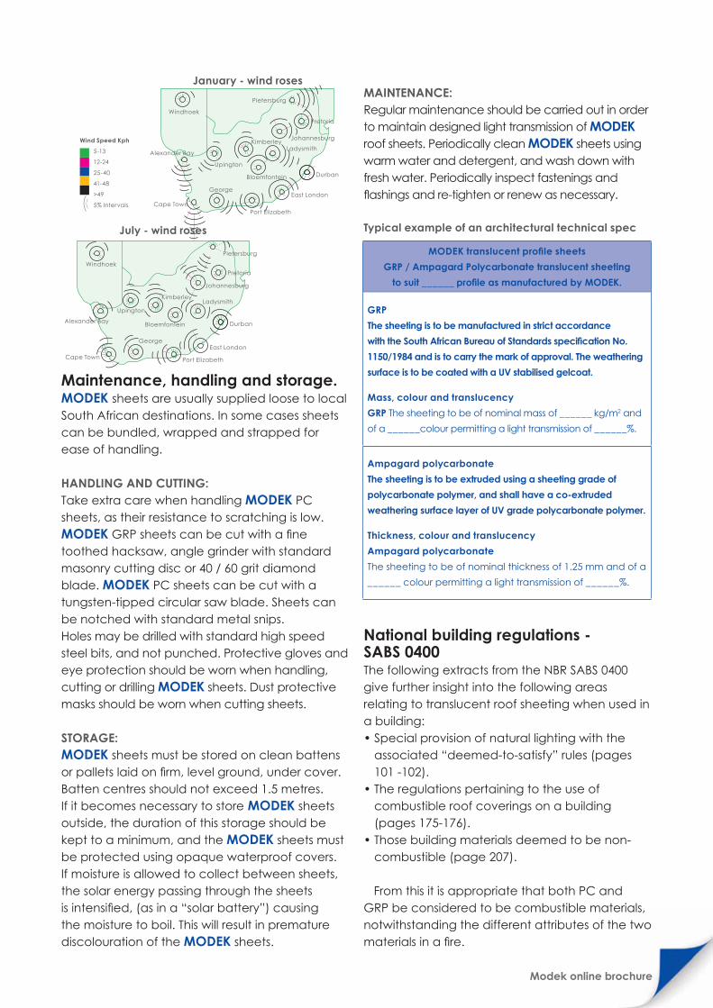
On large projects which take some time to com-plete, consideration must be given to the risk of wind damage which may occur to partially clad build-ings during adverse weather conditions. There are natural variations of wind speeds and directions by region and by season. The South African seasonal wind charts below (as published by the South African Weather Services) give data which could assist in the initial assessment of fastening and installation details.
HC
Radius (r)
r =C² + 4H²
8H
b
Radi
us (r
)
b =r�∞
180
∞°
Modek online brochure
Maintenance, handling and storage.MODEK sheets are usually supplied loose to local South African destinations. In some cases sheets can be bundled, wrapped and strapped for ease of handling.
HANDLING AND CUTTING: Take extra care when handling MODEK PC sheets, as their resistance to scratching is low. MODEK GRP sheets can be cut with a fine toothed hacksaw, angle grinder with standard masonry cutting disc or 40 / 60 grit diamond blade. MODEK PC sheets can be cut with a tungsten-tipped circular saw blade. Sheets can be notched with standard metal snips. Holes may be drilled with standard high speed steel bits, and not punched. Protective gloves and eye protection should be worn when handling, cutting or drilling MODEK sheets. Dust protective masks should be worn when cutting sheets.
STORAGE: MODEK sheets must be stored on clean battens or pallets laid on firm, level ground, under cover. Batten centres should not exceed 1.5 metres. If it becomes necessary to store MODEK sheets outside, the duration of this storage should be kept to a minimum, and the MODEK sheets must be protected using opaque waterproof covers. If moisture is allowed to collect between sheets, the solar energy passing through the sheets is intensified, (as in a “solar battery”) causing the moisture to boil. This will result in premature discolouration of the MODEK sheets.
MAINTENANCE: Regular maintenance should be carried out in order to maintain designed light transmission of MODEK roof sheets. Periodically clean MODEK sheets using warm water and detergent, and wash down with fresh water. Periodically inspect fastenings and flashings and re-tighten or renew as necessary.
Typical example of an architectural technical spec
National building regulations - SABS 0400 The following extracts from the NBR SABS 0400 give further insight into the following areas relating to translucent roof sheeting when used in a building: • Special provision of natural lighting with the
associated “deemed-to-satisfy” rules (pages 101 -102).
• The regulations pertaining to the use of combustible roof coverings on a building (pages 175-176).
• Those building materials deemed to be non-combustible (page 207).
From this it is appropriate that both PC and GRP be considered to be combustible materials, notwithstanding the different attributes of the two materials in a fire.
MODEK translucent profile sheets
GRP / Ampagard Polycarbonate translucent sheeting
to suit ______ profile as manufactured by MODEK.
GRP
The sheeting is to be manufactured in strict accordance
with the South African Bureau of Standards specification No.
1150/1984 and is to carry the mark of approval. The weathering
surface is to be coated with a UV stabilised gelcoat.
Mass, colour and translucency
GRP The sheeting to be of nominal mass of ______ kg/m2 and
of a ______colour permitting a light transmission of ______%.
Ampagard polycarbonate
The sheeting is to be extruded using a sheeting grade of
polycarbonate polymer, and shall have a co-extruded
weathering surface layer of UV grade polycarbonate polymer.
Thickness, colour and translucency
Ampagard polycarbonate
The sheeting to be of nominal thickness of 1.25 mm and of a
______ colour permitting a light transmission of ______%.
George
Cape Town
Alexander Bay
Upington
Port Elizabeth
East London
DurbanBloemfontein
LadysmithKimberley
Johannesburg
Pretoria
Pietersburg
Windhoek
George
Cape Town
Alexander Bay
Upington
Port Elizabeth
East London
DurbanBloemfontein
LadysmithKimberley
Johannesburg
Pretoria
Pietersburg
Windhoek
Wind Speed Kph
5-13
12-24
25-40
41-48
>49
5% Intervals
January - wind roses
July - wind roses

Modek online brochure34
Materials Expansion Comparison. 0°C to 40° temperature variation. Sheet length 12 metres.
Material Comparison
Quick guide - comparison of materials
Material Fibreglass Polycarbonate Safety Glass PVC
Thermal expansion 14.4mm 32.4mm 5.8mm 11.5mm
Thermal co-efficient 3.0 x 10⁻⁵cm/cm˚C 6.75 x 10⁻⁵cm/cm˚C 1.2 x 10⁻⁵cm/cm˚C 2.4 x 10⁻⁵cm/cm˚C
Material Fibreglass Polycarbonate Safety Glass PVC
Transparency Medium Excellent Excellent Excellent
Transparency over period Good Medium Excellent Poor
UV Resistance Good Medium Excellent Poor
Yellowing Good MEdium Excellent Poor
Temperature resistance Excellent Good Excellent Medium
Thermal insulation Good Good Good Good
Sound insulation Good Good Good Good
Impact strength Excellent Excellent Poor Medium
Tear strength Excellent Poor Poor Medium
Rigidity Excellent Good Excellent Good
Fire rating Class 1,2,3,4 Class 0,1 Class 0,1 Class 1
Chemical resistance Excellent Good Excellent Good
Cold curving Good Excellent No Good
Formability No Excellent No Excellent
Life expectancy Excellent Good Excellent Low

Contact UsEast London
PO Box 659
Gonubie
5256
Physical address:
Schoof Street
Wilsonia, East London
Tel: +27 43 707 9200
Fax: +27 43 745 2003
Email: [email protected]
Johannesburg
PO Box 2147
Edenvale
1610
Cnr Nuywerheid & Evergreen Strs
Tunney Township
Elandsfontein, Johannesburg
Tel: +27 11 398 8200
Fax: +27 11 392 5154
Email: [email protected]
Cape Town
PO Box 45
Eppindust
7475
Unit 3, Oude Moulen Park
Oude Moulen Rd
Maitland, Cape Town
Tel: +27 21 511 6816
Fax: +27 21 511 6850
Email: [email protected]
Durban
PO Box 10202
Ashwood
3605
33B Circuit Rd
Westmead
Pinetown, Durban
Tel: +27 31 792 5700
Fax: +27 31 792 5706
Email: [email protected]
Port Elizabeth
PO Box 13909
Humewood
6013
16 Lower Valley Rd
Baakens Valley
Port Elizabeth
Tel: +27 41 585 5566
Fax: +27 41 586 0491
Email: [email protected]
MODEK CredoMODEK regards the customer as the ultimate judge of business performance. Success or failure hinges on the management of customer perceptions. At MODEK superoir service is everybody's business.


