Skin Effect Heat Tracing System - Pistesarjat · ThermTrac Delivers Performance A ThermTrac system...
4
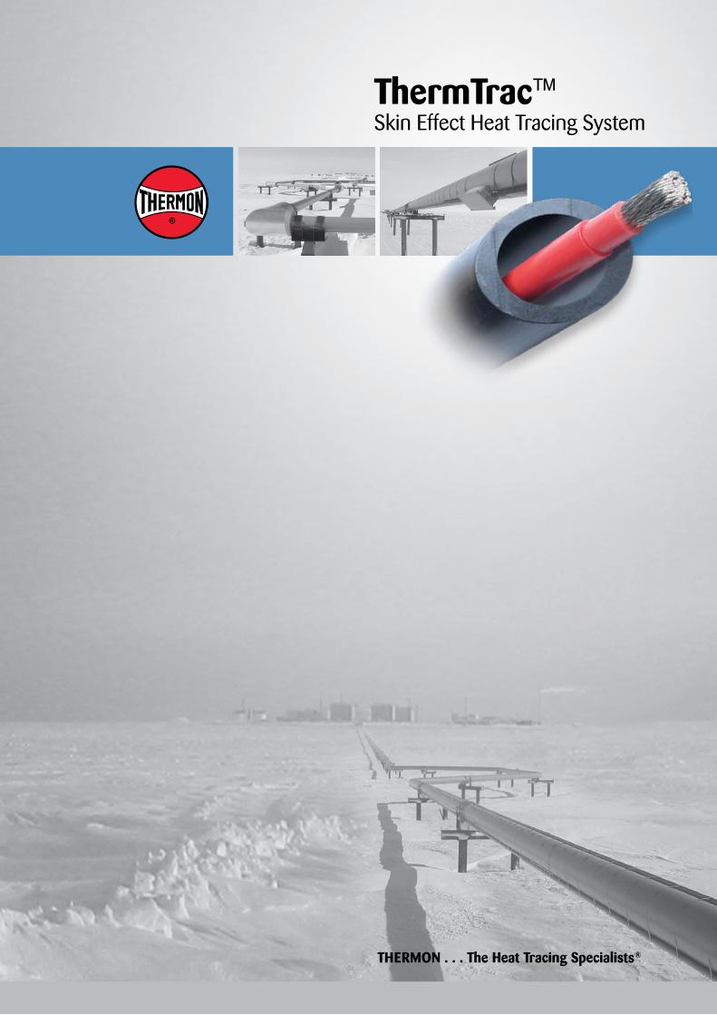
THERMON . . . The Heat Tracing Specialists ® ThermTrac™ Skin Effect Heat Tracing System
Transcript of Skin Effect Heat Tracing System - Pistesarjat · ThermTrac Delivers Performance A ThermTrac system...
THERMON . . . The Heat Tracing Specialists®
ThermTrac™ Skin Effect Heat Tracing System

IntroductionThe ThermTrac system is ideally suited for long pipeline heat-ing applications involving movement of materials to and from tank farms, process units and loading/unloading facilities. The versatility of the system makes it ideal for temperature mainte-nance, freeze protection and heat-up applications. Adaptable to varying site conditions both above and below ground, a ThermTrac system can traverse terrains with significant eleva-tion changes.
A ThermTrac system provides a cost-effective alternative to conventional resistance heat tracing on long line piping by eliminating the need for an extensive power distribution sys-tem. A pipeline up to 25 kilometers long can be traced from a single power point.
Thermon has a proven track record with skin effect heating systems installed around the world in a wide variety of industries including:
•Chemical •Oil•Power •Petrochemical•Gas •Pulp/Paper•Steel •Mining•Refining
Heating System DescriptionThe operating principle of a ThermTrac skin effect heating system is based on two phenomena, proximity effect and skin effect. The heating device is a ferromagnetic pipe, called a “heat tube”, through which a specially designed skin effect conductor has been pulled. The heat tube and insulated conductor are joined together at one end, while at the opposite end the heat tube and the conductor are connected across an AC voltage source (typically 50 or 60 Hz). The impressed AC voltage will generate a current in the conductor which will return through the inside surface of the heat tube. The concentration of the return current on the inside surface of the heat tube is due to the magnetic flux linkages originated by the currents in the insulated conductor and the ferromagnetic pipe. This current penetrates into the heat tube a distance termed the “skin depth.” Due to the phenomena described, there is virtually no measurable voltage on the outer surface of the heat tube, allowing the piping system to be grounded. The heat generated in a ThermTrac system is the result of the resistance that occurs on the inner skin of the heat tube. While the electrical current is concentrated on the inner surface of the heat tube, the heat generated will dissipate from the tube into the attached carrier pipe to increase the surface temperature of the pipe and its contents to a designed level.
A additional advantage of the ThermTrac Skin Effect system is it’s ability to work with a cathodic protection system. Skin effect utilizes an alternating AC power source, while cathodic protec-tion requires a DC potential. Since no voltage exists between the outer wall of the pipe and ground, there is no relationship between the skin effect system and the cathodic protection.
Power Connection Box
Pull Box End Termination Box
To Ground
To Ground
Heat Tube withThermTrac Conductor
Process Pipe
To Field Junction Box
Control Panel
Transformer
Field Junction Box
To Power Connection Box
AC voltage will generate a current in the conductor which returns throught the inside surface of the heat tube. There is virtually no measurable voltage on the outer surface of the heat tube, allowing the piping system to be grounded.
ThermTrac™ Skin Effect Heat Tracing System

ThermTrac DeliversPerformance
A ThermTrac system meets the demanding heat tracing require-ments of long line piping: 1
Power Outputs ............................................... up to 165 W/mSystem operating voltages ...................................... up to 5 KvMaintenance temperature ................................... up to 200°CExposure temperature .........................................up to 260°CMinimum installation temperature ...................down to -40°CT-rating 2 ....................................................................T6 to T2
Notes . . .
1. Each ThermTrac system is custom designed for the application. Please consult Ther-mon for specific project details.
2. Hazardous area temperature classifications are determined for each installation in accordance with the guidelines set forth in IEEE Std 844, IEEE Recommended Practice for Electrical Impedance, Induction, and Skin Effect Heating of Pipelines and Vessels.
Reliability
Typically, long line piping is located in areas where access is limited. Frequent maintenance and troubleshooting are costly in both time and money. Since one ThermTrac circuit can heat trace over six times the length of pipe that could be protected using conventional resistance heating cables, the power distribution and temperature control requirements are significantly reduced.
Design Solutions
Thermon engineers evaluate the design parameters of each application using CompuTrace® heat tracing design software and analytical thermal modeling technologies including Finite Element Analysis (FEA) and Computational Fluid Dynamics (CFD). Based on any design requirements or limitations, nu-merous options are reviewed to establish the best solution for the specific project.
THERMON . . . The Heat Tracing Specialists®
A ThermTrac System IncludesThermon custom-engineers every ThermTrac system to meet the requirements of each specific application. The Thermon scope of work typically includes:
• Reviewing the application’s design parameters and calculat-ing the heating requirements using CompuTrace and thermal modeling as necessary.
• Selecting the heat tube size, ThermTrac conductor and secondary voltage required to feed electrical power to the system.
• Designing and supplying the transformer and control panel including temperature sensor.
• Designing and supplying ancillary equipment consisting of field junction boxes, power connection boxes, end termina-tion boxes and pull boxes.
• Providing engineered drawings indicating heat tube routing, box locations, electrical wiring diagrams, field connections, transformer connections and power distribution and control panel connections, plus operation and maintenance manuals for the complete system.
• Supplying specifications for the carbon steel heat tube and related accessories including specifications for installation, welding and testing.
Transformer and Control PanelThe Transformer and Control Panel is designed to meet the requirements of each specific project based on the available voltage, load requirements, number of circuits and the operat-ing environment. The power/load center typically consists of a specialty transformer equipped with over/under primary taps and additional power adjustment taps on the secondary side. Load contactors, circuit overload protection and other protec-tive devices also form a part of the load center. When multiple skin effect circuits exist (powered from a common location), Scott-tee type transformers may be used to balance a three-phase power supply to feed two ThermTrac circuits.
The control and monitoring panel typically includes temperature control and monitoring with high and low temperature alarms, differential current relay safety protection and current/voltage monitoring.

Form TEP0041U--0909 © Thermon Manufacturing Co. Printed in U.S.A.
Thermon WorldwideWith global manufacturing and warehouse facilities, Thermon supplies heat tracing products to meet the needs of customers around the world. Thermon offers complete heating solutions, including heating cables and terminations, control systems, engineering/design services, and installation.
Heat Tracing Software
CompuTrace® is an integral part of Thermon’s heat tracing package. Whether your project involves win-terization, maintenance of elevated temperatures, complex piping, long piping runs or any combina-tion of these, CompuTrace has what it takes to help design your heat trac-ing system.
CompuTrace allows the user to perform designs in compliance with four globally recognized electrical standards. The program performs heat up calculations us-ing any of Thermon’s cables. Five report formats are available to choose from. All reports can be export-ed to a Microsoft Excel compatible file for electronic file transfer or customization.
Electric Heat Tracing
The demands placed on heat tracing systems vary based on the design parameters specif-ic to each application. To meet these needs, Thermon manufactures the widest variety of electric heating cables and control systems in the world.
•Self-Regulating•Power-Limiting•ParallelConstantWatt•SeriesConstantWatt•MineralInsulated•SkinEffect•TankandHopperHeating•CompleteControlSystems
AmericasAcworth, Georgia
Baton Rouge, Louisiana
El Dorado Hills, California
Houston, Texas
Huntersville, North Carolina
Mogadore, Ohio
San Marcos, Texas
Wilmington, Delaware
Mexico City, Mexico
CanadaCalgary, Alberta
Edmonton, Alberta
Sarnia, Ontario
St. Laurent, Quebec
Sallisbury, New Brunswick
EuropePijnacker, The Netherlands
Newcastle, England
Paris, France
Gladbach, Germany
Moscow, Russia
Asia PacificMelbourne, Australia
Sydney, Australia
Auckland, New Zealand
Kuala Lumpur, Malaysia
Beijing, China
Shanghai, China
Mumbai, India
Calcutta, India
Yokohama, Japan
Seoul, Korea
THERMON . . . The Heat Tracing Specialists®
Corporate Headquarters100 Thermon Dr. • PO Box 609San Marcos, TX 78667-0609 • USAPhone: +1 512-396-5801
European HeadquartersBoezemweg 25 • PO Box 2052640 AE Pijnacker • The NetherlandsPhone: +31 (0) 15-36 15 370
For the Thermon office nearest you visit us at . . .
www.thermon.com