SKF Rail guide tables - INFN Genovadarbo/SQTF/LoadingRobot/... · easily copy the drawing of the...
38
Linear Motion SKF Rail guide tables
Transcript of SKF Rail guide tables - INFN Genovadarbo/SQTF/LoadingRobot/... · easily copy the drawing of the...

Linear Motion
SKF Rail guide tables

The SKF Group
The SKF Group is an internationalindustrial corporation of AB SKF Sweden, founded in 1907, operat-ing in 130 countries. The companyhas some 45000 employees andmore than 80 manufacturing facili-ties throughout the world. Its international network is support-ed up by nearly 20000 distributorsand retailers. SKF is the worldleader in the rolling bearing busi-ness.Bearings, seals and special steelsare SKF’s main product areas. Inaddition, they also manufactureand sell, other industrial precisioncomponents and products.
© Copyright SKF 2003The contents of this catalogue arethe copyright of the publishers andmay not be reproduced (evenextracts) unless permission is gran-ted. Every care has been taken toensure the accuracy of the infor-mation contained in this cataloguebut no liability can be accepted forany errors or omissions.
Earlier catalogues the data in whichdeviate from those given here, arerendered invalid.The right is reserved to makechanges necessitated by technolo-gical developments.
Catalogue n° 5172 E / I47173 · 3000 · 2003-04
Printed in Germanyby Weppert GmbH & Co. KG
SKF Linear Motion
One of these industrial precisionproducts assortment is manufac-tured and sold by the SKF LinearMotion Division.This unit has some 700 employees,6 manufacturing facilities, 3 prod-uct lines. One of the division’sstrengths is its ability to serve themarket through its organizationbased on 11 specialized SalesCompanies located in Europe andNorth America; however productavailability and product applicationsupport is provided word-wide bythe SKF international network.
The Linear Motion product rangecovers:• High Efficiency Screws• Linear Guiding Systems• Electromechanical Actuators
CD-ROM “Designer”
All linear Motion products are avai-lable in this CD, in DWG and DXFfiles.Thanks to “Designer”, you caneasily copy the drawing of the product you need into your owndesign drawing. If you are inte-rested, please do not hesitate tocontact your local SKF sales orga-nization. It is free of charge.
Linear Motionspecialized companies
SKF Bearing companieswith Linear Motionspecialized salesforce
Manufacturing facilities

4
10
14
18
26
30
31
32
34
35
Design and characteristic features
Tables LTB 110
Tables LTB 170
Tables LTB 235
Tables LTB 320
Tables LTB 400
Ordering details
Application samples
Axes layout
Specification sheet

3
Design and characteristic features .............................................................. 4General ............................................................................................................ 4Guide ............................................................................................................... 4Drive ................................................................................................................ 6Cover ............................................................................................................... 8Precision classes ............................................................................................. 8Stroke .............................................................................................................. 9Materials .......................................................................................................... 9Permissible operating temperature ................................................................. 9Lubrication ....................................................................................................... 9Load carrying capacity and life ....................................................................... 9Accessories ..................................................................................................... 9
Tables ............................................................................................................. 10LTB110 rail guide tables with ball screw drive ................................................. 10LTB110 rail guide tables with linear motor drive .............................................. 12
LTB170 rail guide tables with ball screw drive ................................................. 14LTB170 rail guide tables with linear motor drive .............................................. 16
LTB235 rail guide tables with ball screw drive ................................................. 18LTB235 rail guide tables with linear motor drive .............................................. 22
LTB320 rail guide tables with ball screw drive ................................................. 26LTB320 rail guide tables with linear motor drive .............................................. 28
LTB400 rail guide tables with ball screw drive ................................................. 30
Ordering details ............................................................................................. 31
Application samples ...................................................................................... 32
Axes layout ..................................................................................................... 34
Specification sheet ........................................................................................ 35
Contents

4
General
SKF rail guide tables are state-of-the-art tables with high accuracy and highload carrying capacity. They are available in the following variations:• five different sizes, • three different covers • two different drives • four precision classes.
Sizes:
SKF rail guide tables are available inwidths of 110, 170, 235, 320 and 400 mm.
Drives:
Two different drives can be fitted: ballscrews and linear motors.
Cover:
The rail guide tables can be suppliedin three versions: without cover, withbellows, with steel cover.
Precision classes:
Depending on their application, theslides are available in four precisionclasses: P10, P5, P2, P1.
Customer benefits:
• Modular and compact design.• Variants having high load carrying
capacity and stiffness.• Large number of drives, providing
the optimum solution for any appli-cation.
• Different covers to suit the environ-mental conditions.
• Precision class matched with appli-cation, thus more cost-efficient.
Design and characteristic features
Guide
SKF rail guide tables are equippedwith a pair of rails fitted with a total offour carriages (with the exception ofsize 110 with linear motor F 22706 ha-ving six carriages).
Customer benefits:
• Profile rail with high load carryingcapacity and stiffness
See Table 1 for further technical de-tails.

5
Table 1: Load carrying capacity of the tables
Type Precision Load rating per No. of Distance Maximum static load per table1)
Size class carriage carriagesC Co z b l h3) Foz Foy Mox Moy Moz
N – mm N Nm
LTB110.L1.SH/TN P10 - P1 2.295 4.270 4 81 69 23 17.080 8.540 690 580 290LTB110.L1.F20906 P5 - P1 2.295 4.270 4 81 63 23 16.880 8.440 680 530 260LTB110.L1.F21806 P5 - P1 2.295 4.270 4 81 130 23 16.680 8.340 670 1.080 540LTB110.L1.F22706 P5 - P1 2.295 4.270 6 81 220 23 25.020 12.510 1.010 2.750 1.370
LTB170.L1.SH/TN P10 - P1 7.800 13.500 4 116 92 35 54.000 27.000 3.130 2.480 1.240LTB170.L1.F21806 P5 - P1 7.800 13.500 4 116 124 35 53.600 26.800 3.100 3.320 1.660LTB170.L1.F22706 P5 - P1 7.800 13.500 4 116 195 35 53.400 26.700 3.090 5.200 2.600
LTB235.L1.SX/TN/TL P10 - P1 18.800 24.400 4 156 140 46 97.600 48.800 7.610 6.830 3.410LTB235.L1.A32008 P5 - P1 18.800 24.400 4 156 142 46 95.800 47.900 7.470 6.800 3.400LTB235.L1.A33008 P5 - P1 18.800 24.400 4 156 177 46 94.900 47.450 7.400 8.390 4.190LTB235.L1.A34008 P5 - P1 18.800 24.400 4 156 262 46 94.000 47.000 7.330 12.310 6.150
LTB320.L1.SX/TN/TL P10 - P1 22.800 30.400 4 220 221 70 121.600 60.800 13.370 13.430 6.710LTB320.L1.A32014 P5 - P1 22.800 30.400 4 220 160 70 118.000 59.000 12.980 9.440 4.720LTB320.L1.A33014 P5 - P1 22.800 30.400 4 220 185 70 116.000 58.100 12.780 10.740 5.370LTB320.L1.A34014 P5 - P1 22.800 30.400 4 220 275 70 114.000 57.200 12.580 15.730 7.860
LTB400.L1.SX/TN/TL P10 - P1 41.900 54.000 4 270 270 77 216.000 108.000 29.160 29.160 14.580
1) Loads Foz and Foy for central load application, but not for slides with steel cover.Moments Mox to Moz for pure moment load (without force), but not for slides with steel cover.
2) Distance up to the middle of the rail

6
Drive
Tables with a ball screw:
These tables are equipped with precision rolled thread ballscrewdrives.
Screws SH and SX have a nut withinternal ball recirculation. They are notpreloaded, the axial clearance is
Table 2: Ball screw technical details
0.1 mm maximum. These screws arethe standard for precision class P10 tables. On request also for P5.
Screws TN and TL are fitted withan internal preloaded nut. TL screwshave long leads and are therefore sui-table for high travel speeds. They canbe fitted in tables of precision classesP5 to P1.
Benefits:
• Robust drive.• Suitable for high axial forces.• Any drive can be fitted, e.g. manual
drive, DC, AC or stepped motor.• Attachment via motor flange or
indirect toothed belt drive.
See Table 2 for further technical infor-mation.
Table Screw Load rating2) Table drive torqueNominal Max.
Type Precision Type diameter Lead Lead accuracy1) dynamic static idling permissibleSize class Size do p acc. to ISO V300p Ca Coa Ms Ma
mm µm/300 mm N Nm
LTB110 P10-P5 SH1205 12 5 G9 87 3.100 5.100 0,17 2,6P5-P1 TN1205 12 5 G7 40 6.060 7.100 0,27 2,6P5-P1 TN1210 12 10 G7 40 3.730 3.550 0,30 2,6
LTB170 P10-P5 SH1605 16 5 G9 87 5.200 8.700 0,18 5,8P5-P1 TN1605 16 5 G7 40 10.710 12.720 0,33 8,4P5-P1 TN1610 16 10 G7 40 10.710 12.720 0,38 12,0P5-P1 TN1616 16 16 G7 40 6.590 6.360 0,42 12,0
LTB235 P10-P5 SX2505 25 5 G9 87 15.600 31.000 0,19 20,6P10-P5 SX2510 25 10 G9 87 18.800 31.000 0,21 32,9P5-P1 TN2505 25 5 G7 40 12.700 22.440 0,49 14,9P5-P1 TN2510 25 10 G7 40 12.700 22.440 0,61 29,8P5-P1 TL2520 25 20 G7 40 12.700 22.440 0,62 32,9P5-P1 TL2525 25 25 G7 40 7.820 11.220 0,65 32,9
LTB320 P10-P5 SX3205 32 5 G9 87 17.800 50.400 0,19 33,4P10-P5 SX3210 32 10 G9 87 27.500 55.000 0,22 72,9P5-P1 TN3205 32 5 G7 40 14.210 30.960 0,59 20,5P5-P1 TN3210 32 10 G7 40 23.390 40.960 0,82 54,3P5-P1 TL3220 32 20 G7 40 23.390 40.960 0,72 96,0P5-P1 TL3232 32 32 G7 40 14.400 20.480 0,84 86,9P5-P1 TL3240 32 40 G7 40 14.400 20.480 0,88 96,0
LTB400 P10-P5 SX4005 40 5 G9 87 19.500 63.100 0,21 41,8P10-P5 SX4010 40 10 G9 87 29.000 64.000 0,26 84,9P5-P1 TN4005 40 5 G7 40 20.350 59.580 0,81 39,3P5-P1 TN4010 40 10 G7 40 29.000 64.000 1,66 84,9P5-P1 TL4020 40 20 G7 40 29.000 64.000 0,90 169,7P5-P1 TL4040 40 40 G7 40 25.500 35.120 1,09 186,3
1) Lead accuracy G5 at V300p = 23 µm/300 mm available on request.2) Value indicated = minimum load rating of either screw or locating bearing
Design and characteristic features

7
Tables with a linear motor drive:
These are equipped with brushlessAC motors and work as follows:• The secondary part in the lower part
of the table takes the form of a magnetic rail.
• The primary part is located in the travelling upper part of the table andtakes the form of a coil system.
• Two or three-phase AC synchronousmotors with electronic commutation.
• Linear measuring system, integratedin the table as standard.
Table 3: Linear motor technical details
Customer benefits:
• High dynamics and stiffness in a closed loop system.
• Good synchronous characteristics.• High acceleration capacity.• High travel speeds, even with large
strokes.• Friction and wear free drive.
See Table 3 for further technical de-tails.
For table: LTB 110 110+170 235 320Motor size F20906 F21806 F22706 A32008 A33008 A34008 A32014 A33014 A34014Number of motor phases 2P 2P 3P 3PStatic maximum force Fp N 105 210 315 600 900 1.200 1.200 1.800 2.400Nominal force Fn N 33 66 100 190 285 379 379 596 759Power loss at Fp Pvp W 212 424 637 424 643 907 690 1.043 1.381Power loss at Fn Pvn W 21 42 64 42 91 69 104 138Motor constant km N/W-2 7,2 10,2 12,5 29,1 35,5 39,8 45,7 55,7 64,6Attractive force between motor parts Fa N 200 400 600 1.800 2.700 3.600 3.600 5.400 7.200Force constant kf N/Aeff 19,7 19,7 19,7 74 74 74 148 148 148Dyn. force at vlim Flim N 70 160 250 430 750 1.100 900 1.550 2.200Linear limiting speed at Flim vlim m/s 3,0 1) 3,0 1) 3,0 1) 2,5 2,4 2,3 1,3 1,2 1,1Maximum current Ip Aeff 5,3 10,6 16,0 8,1 12,2 16,2 8,1 12,2 16,2Continuons current In Aeff 1,7 3,4 5,0 2,6 3,8 5,1 2,6 3,8 5,1DC-link Voltage Uzk V 80 80 80 300 300 300 300 300 300Linear measuring system:Signal output Standard: sinus signal, 1Vss, grading rate 20µm;
Option: TTL-signal resolution 0,1 - 0,2 - 0,5 - 1µm, after 4-fold interpolation
Limit-/Ref. switch 2 switches integrated inside the measuring system, PNP/NC or NPN/NC possiblePrecision class Standard: ±5µm; option: ±3µm or ±2µm
1) limited by linear guiding

8
Cover
The slides with ball screw and linearmotor drive are available as follows:• With bellows made of oil and
water resistant polyurethane fibrematerial on both sides.The carriages and ballscrew nut areadditionally protected by wipers (withthe exception of the SH screws). Thescrew thrust bearings are also sealed.
• Without cover for applications with-out exposure to dirt, e.g. in labora-tories. The carriages, ballscrew nutand bearings are sealed as they arein the bellows version. The effectivestroke is, of course, longer than inthe bellows version.
Design and characteristic features
• With steel cover, made from corrosionresistant steel sheet, for applicationswith extreme exposure to dirt fromabove or for those applicationswhere shock impacts on the covercannot be excluded. The effectivestroke is as long as in the versionwithout cover.
Diagram 1: Precision
100 300 900 1300 1700 2100
50
0
100
150
P10
P5
P2
P1
500 700 1100 1500 1900 2300 2500
Str
aigh
tnes
s Tz
/Ty
[µm
]
Stroke [mm]
Precision classesThe characteristics of the differentprecision classes are listed in the table below.
The precision given in Diagram 1applies to a single table in clampedcondition on an ideal plane clampingsurface.
Straightness defined as in VDI2617 sheet 3.

9
Stroke
The strokes S1 (with bellows), S2 (with-out bellows) and S (with steel cover)are the maximum travel distancesbetween the end stops. Depending onthe speed and the moving mass theoperating stroke is correspondinglyless. The overrun on both sides mustbe larger than the length of the brakepath of the drive. The value of 2 x p (spindle lead) can be considered to bea reliable guideline value.
Materials
As standard, the table componentsare made of aluminium and are blackoxidised. The bottom part of the tableis made of untreated aluminium. Onrequest the bottom part and the toppart are also available in steel.
Permissible operating temperature
Tables with screw drives:-20°C to +80°C constant temperature.Linear motor slides: 0°C to + 55°C constant temperature.
Lubrication The guides and screw are greasedwith an all-purpose SKF grease by themanufacturing unit. The carriages andthe screw nut can be relubricated. Forfurther information please refer to theoperating instructions.On the carriages can be fitted with acentral lubricating connection. Five lu-bricating holes are provided in the si-de plate. (Not possible by using car-riages with steel cover.)Relubrication intervals depending onoperating conditions:20 - 200 km or after1 year at the latest.
Load carrying capacity and life
For exact dimensioning and design ofSKF rail guide tables and drives plea-se contact SKF Linear Motion. In or-der to provide the required data cor-rectly, please fill in the specificationsheet on page 35.
Accessories
Limit and reference switches
Tables with ball screw drives are fittedwith inductive limit switches PNP/NCas standard and can be equippedwith inductive reference switches onrequest. These are integral with theslide. They are connected via a cen-tral plug connection on one of the endplates (see dimension specifications).
Slides with linear motor drive arefitted with 2 limit/reference switchesPNP/NC or NPN/NC, which are inte-grated in the linear measuring system.
Cross table assembly
Individual tables can be mounted toform a cross table. The standard drillhole patterns of the table top and bot-tom parts are matched so that moun-ting of the same or next smaller size ispossible. Please note the details inthe corresponding column of the di-mensional specifications.
Linear measuring system
The attachment of a direct linear mea-surement system is possible. The sli-des with linear motor drive are equip-ped with a linear measuring system asstandard. It is integral with the table.Further information can be found inTable 3 on page 7.
Motor flange
The slides with ball screw drives canbe equipped with a motor flange andcoupling on request. When orderingplease indicate the motor manufactu-rer, model and type.
Indirect toothed belt drive
If space is restricted, an indirect driveusing a toothed belt may be the bestchoice. The motor can be mounted oneither the right or left hand side. Stan-dard transmission ratio 1:1.
Linear motor control units and control components
The following components are avail-able for controlling the linear motors:• Dividing electronics for measuring
system, integrated in the table• Servo module • Point-to-point or continuous path
control
Further information available on re-quest or in the offer as submitted.

LTB 110.L1.SH/TN12xx-BL Rail guide tables with ball screw drive with or without bellows
1) Plug connection for limit and reference switches (optional) Direction of travel - <---> +
T slots in bottom part:Slot 1: for square nut DIN 562 M5Slot 2: for square nut DIN 562 M4
10
Length Screw data2) Stroke3) SH1205 TN1205+1210 Weight4)
L1 L3 n KN S1 S2 nmax nmax GA GO
mm – mm 1/min kg
150 15 3 20 30 4160 7500 1,7 0,8190 15 4 x 45 70 4160 7500 1,6230 15 5 70 110 4160 7500 1,8270 15 6 x 95 150 4160 7500 2,0310 15 7 115 190 4160 7500 2,2350 15 8 x 140 230 4160 7500 2,4390 15 9 165 270 4160 7500 2,6430 15 10 x 190 310 4160 7500 2,7470 15 11 215 350 4160 7500 2,9510 15 12 x 240 390 4160 7500 3,1550 15 13 265 430 4160 6370 3,3590 15 14 x 285 470 4160 5420 3,5630 15 15 310 510 4160 4670 3,6670 15 16 x 335 550 3900 4060 3,8710 15 17 360 590 3420 3570 4,0750 15 18 x 385 630 3030 3160 4,2790 15 19 410 670 2700 2810 4,4830 15 20 x 430 710 2420 2520 4,5870 15 21 455 750 2180 2280 4,7910 15 22 x 480 790 1980 2060 4,9950 15 23 505 830 1800 1880 5,1
4) GA = Total mass of tableGO = Mobile mass of table top
2) Suitable as top axis for centralcross table mounting
3) Maximum stroke between end stops:S1 with bellows (standard version)S2 without bellows (special version)

11
Length Screw data2) Stroke3) SH1205 TN1205+1210 Weight4)
L1 L3 n KN S nmax nmax GA GO
mm – mm 1/min kg
150 15 3 30 4160 7500 2,0 0,9190 15 4 x 70 4160 7500 2,2230 15 5 110 4160 7500 2,4270 15 6 x 150 4160 7500 2,6310 15 7 190 4160 7500 2,8350 15 8 x 230 4160 7500 3,0390 15 9 270 4160 7500 3,2430 15 10 x 310 4160 7500 3,4470 15 11 350 4160 7500 3,6510 15 12 x 390 4160 7500 3,8550 15 13 430 4160 6370 4,0590 15 14 x 470 4160 5420 4,2630 15 15 510 4160 4670 4,4670 15 16 x 550 3900 4060 4,6710 15 17 590 3420 3570 4,8750 15 18 x 630 3030 3160 5,0790 15 19 670 2700 2810 5,2830 15 20 x 710 2420 2520 5,4870 15 21 750 2180 2280 5,6910 15 22 x 790 1980 2060 5,8950 15 23 830 1800 1880 6,0
LTB 110.L1.SH/TN12xx-SC Rail guide tables with ball screw drive with steel cover
1) Plug connection for limit and reference switches (optional) Direction of travel - <---> +
T slots in bottom part:Slot 1: for square nut DIN 562 M5Slot 2: for square nut DIN 562 M4
4) GA = Total mass of tableGO = Mobile mass of table top
2) Suitable as top axis for centralcross table mounting
3) Maximum stroke between end stops

12
Length F20906 F21806 F227062) 4) Stroke3) 5) Stroke3) 5) Stroke3) 5)
L1 L3 n KN GU L2 S1 S2 GO L2 S1 S2 GO L2 S1 S2 GO
mm – kg mm kg mm kg mm kg
150 15 3 1,3 110 20 30 0,9 190 1,5 280 2,1190 15 4 x 1,5 45 70230 15 5 2,0 70 110 20 30270 15 6 x 2,2 95 150 45 70310 15 7 2,5 115 190 70 110350 15 8 x 2,9 140 230 95 150 40 60390 15 9 3,2 165 270 115 190 65 100430 15 10 x 3,5 190 310 140 230 90 140470 15 11 3,9 215 350 165 270 110 180510 15 12 x 4,1 240 390 190 310 135 220550 15 13 4,4 265 430 215 350 160 260590 15 14 x 4,8 285 470 240 390 185 300630 15 15 5,1 310 510 265 430 210 340670 15 16 x 5,4 335 550 285 470 235 380710 15 17 5,8 360 590 310 510 260 420750 15 18 x 6,0 385 630 335 550 280 460790 15 19 6,3 410 670 360 590 305 500830 15 20 x 6,7 430 710 385 630 330 540870 15 21 7,0 455 750 410 670 355 580910 15 22 x 7,3 480 790 430 710 380 620950 15 23 7,7 505 830 455 750 405 660
LTB 110.L1.F2xxxx-BL Rail guide tables with linear motor drive with or without bellows
A Cable output for motor and measuring system. Flat ribbon cable 20 x 6.3 mm Direction of travel: - <---> +
T slots in bottom part:Slot 1: for square nut DIN 562 M5
4) GU = Stationary mass of bottom partGO = Mobile mass of table top
2) Suitable as top axis for central crosstable mounting
3) Maximum stroke between end stops:S1 with bellows (standard version)S2 without bellows (special version)

13
Lenght F20906 F21806 F227062) 4) Stroke3) 5) Stroke3) 5) Stroke3) 5)
L1 L3 n KN GU L2 S n4xL4 GO L2 S n4xL4 GO L2 S n4xL4 GO
mm – kg mm kg mm kg mm kg
150 15 3 1,3 110 30 2x40 1,2 190 4x40 2,0 280 6x40 2,8190 15 4 x 1,6 70230 15 5 2,1 110 30270 15 6 x 2,3 150 70310 15 7 2,6 190 110350 15 8 x 3,1 230 150 60390 15 9 3,4 270 190 100430 15 10 x 3,7 310 230 140470 15 11 4,1 350 270 180510 15 12 x 4,4 390 310 220550 15 13 4,7 430 350 260590 15 14 x 5,1 470 390 300630 15 15 5,4 510 430 340670 15 16 x 5,7 550 470 380710 15 17 6,1 590 510 420750 15 18 x 6,4 630 550 460790 15 19 6,7 670 590 500830 15 20 x 7,1 710 630 540870 15 21 7,4 750 670 580910 15 22 x 7,7 790 710 620950 15 23 8,2 830 750 660
LTB 110.L1.F2xxxx-SC Rail guide tables with linear motor drive with steel coverT slots in bottom part:
Slot 1: for square nut DIN 562 M5
A Cable output for motor and measuring system. Flat ribbon cable 20 x 6.3 mm Direction of travel: - <---> +
4) GU = Stationary mass of bottom partGO = Mobile mass of table top
2) Suitable as top axis for central crosstable mounting
3) Maximum stroke between end stops

Lenght Screw data2) Stroke 3) SH1605 TN1605 TN1610 TN1616 Weight4)
L1 L3 n KN S1 S2 nmax nmax nmax nmax GA GO
mm – mm 1/min kg
220 50 1 x 35 40 3120 5620 5620 5620 5,7 2,3280 20 2 80 100 3120 5620 5620 5620 6,4340 50 2 125 160 3120 5620 5620 5620 7,1400 20 3 x 175 220 3120 5620 5620 5620 7,8460 50 3 x 220 280 3120 5620 5620 5620 8,5520 20 4 260 340 3120 5620 5620 5620 9,2580 50 4 305 400 3120 5620 5620 5620 9,9640 20 5 x 355 460 3120 5620 5620 5620 10,6700 50 5 x 400 520 3120 5620 5620 5620 11,3760 20 6 445 580 3120 4670 4670 4670 12,0820 50 6 495 640 3120 3900 3900 3900 12,7880 20 7 x 540 700 3120 3300 3300 3300 13,4940 50 7 x 580 760 2830 2830 2830 2830 14,11000 20 8 625 820 2460 2460 2460 2460 14,81060 50 8 675 880 2150 2150 2150 2150 15,61120 20 9 x 720 940 1900 1900 1900 1900 16,31180 50 9 x 765 1000 1690 1690 1690 1690 17,01240 20 10 815 1060 1510 1510 1510 1510 17,71300 50 10 860 1120 1360 1360 1360 1360 18,41360 20 11 x 900 1180 1230 1230 1230 1230 19,11420 50 11 x 945 1240 1120 1120 1120 1120 19,81480 20 12 995 1300 1020 1020 1020 1020 20,51540 50 12 1040 1360 930 930 930 930 21,21600 20 13 x 1085 1420 860 860 860 860 21,9
LTB 170.L1.SH/TN16xx-BL Rail guide tables with ball screw drive with or without bellows
1) Plug connection for limit and reference switches (optional) Direction of travel: - <---> +
T slots in bottom part:Slot 1: for square nut DIN 562 M6Slot 2: for square nut DIN 562 M4
14
170
15 L1 10
15
116
6.5
52
146
120
4040
40
146
L3 n x 120 L3
10
14
19
32
M6 (4x)M5 (8x)
60
70170
30
35
M6 (4x)
Ø 1
0 h
7
Ø 6
3
Km6
4) GA = Total weight of tableGO = Weight of mobile mass of table top
2) Suitable as top axis for central crosstable mounting
3) Maximum stroke between end stops:S1 with bellows (standard version)S2 without bellows (special version)

15
Lenght Screw data2) Stroke3) SH1605 TN1605 TN1610 TN1616 Weight4)
L1 L3 n KN S nmax nmax nmax nmax GA GO
mm – mm 1/min kg
220 50 1 x 40 3120 5620 5620 5620 6,9 3,3280 20 2 100 3120 5620 5620 5620 7,7340 50 2 160 3120 5620 5620 5620 8,4400 20 3 x 220 3120 5620 5620 5620 9,2460 50 3 x 280 3120 5620 5620 5620 9,9520 20 4 340 3120 5620 5620 5620 10,7580 50 4 400 3120 5620 5620 5620 11,5640 20 5 x 460 3120 5620 5620 5620 12,2700 50 5 x 520 3120 5620 5620 5620 13,0760 20 6 580 3120 4670 4670 4670 13,8820 50 6 640 3120 3900 3900 3900 14,5880 20 7 x 700 3120 3300 3300 330 15,3940 50 7 x 760 2830 2830 2830 2830 16,01000 20 8 820 2460 2460 2460 2460 16,81060 50 8 880 2150 2150 2150 2150 17,61120 20 9 x 940 1900 1900 1900 1900 18,31180 50 9 x 1000 1690 1690 1690 1690 19,11240 20 10 1060 1510 1510 1510 1510 19,91300 50 10 1120 1360 1360 1360 1360 20,61360 20 11 x 1180 1230 1230 1230 1230 21,41420 50 11 x 1240 1120 1120 1120 1120 22,11480 20 12 1300 1020 1020 1020 1020 22,91540 50 12 1360 930 930 930 930 23,71600 20 13 x 1420 860 860 860 860 24,4
LTB 170.L1.SH/TN16xx-SC Rail guide tables with ball screw drive with steel cover
4) GA = Stationary mass of bottom partGO = Mobile mass of table top
1) Plug connection for limit and reference switches (optional) Direction of travel: - <---> +
T slots in bottom part:Slot 1: for square nut DIN 562 M6Slot 2: for square nut DIN 562 M4
170
15 L1 10
15
116
6.5
52146
60 60
15 L3 n x 120 L3 10
10
14
19
32
ÿ10
h7
63ÿ
146
180
M6 (4x)M5 (8x)
M5 (6x)
120
4040
40
Km6
170
70 202
30
35
166169
M6 (4x)
191
2) Suitable as top axis for central crosstable mounting
3) Maximum stroke between end stops

Lenght F21806 F227062) 4) Stroke3) 5) Stroke3) 5)
L1 L3 n KN GU L2 S1 S2 GO L2 S1 S2 GO
mm – kg mm kg mm kg
280 20 2 4,5 200 55 70 3,0 280 3,9340 50 2 5,3 105 130 40 50400 20 3 x 6,2 150 190 90 110460 50 3 x 7,1 195 250 135 170520 20 4 8,0 240 310 180 230580 50 4 8,9 285 370 220 290640 20 5 x 9,8 330 430 270 350700 50 5 x 10,7 375 490 315 410760 20 6 11,5 425 550 360 470820 50 6 12,4 470 610 410 530880 20 7 x 13,3 515 670 455 590940 50 7 x 14,2 565 730 500 6501000 20 8 15,1 605 790 545 7101060 50 8 16,0 650 850 590 7701120 20 9 x 16,9 695 910 635 8301180 50 9 x 17,7 745 970 680 8901240 20 10 18,6 790 1030 730 9501300 50 10 19,5 835 1090 775 10101360 20 11 x 20,4 885 1150 820 10701420 50 11 x 21,3 925 1210 865 11301480 20 12 22,2 970 1270 910 11901540 50 12 23,1 1015 1330 955 12501600 20 13 x 23,9 1065 1390 1000 1310
LTB 170.L1.F2xxxx-BL Rail guide tables with linear motor drive with or without bellowsT slots in bottom part:
Slot 1: for square nut DIN 562 M6Slot 2: for square nut DIN 562 M4
16
L2
8 L1 8
15
116
6.5
52
146
120
4040
40
146
L3 n x 120 L3
Km6M6 (4x)M5 (8x) 60
170
36
28.5
A Cable output for motor and measuring system. Flat ribbon cable 20 x 6.3 mm Direction of travel: - <---> +
4) GU = Stationary mass of bottom partGO = Mobile mass of table top
2) Suitable as top axis for central crosstable mounting
3) Maximum stroke between end stops:S1 with bellows (standard version)S2 without bellows (special version)

17
Lenght F21806 F227062) 4) Stroke3) 5) Stroke3) 5)
L1 L3 n KN GU L2 S n4xL4 GO L2 S n4xL4 GO
mm – kg mm kg mm kg
280 20 2 4,5 200 70 2x75 4,2 280 3x75 5,6340 50 2 5,4 130 50400 20 3 x 6,3 190 110460 50 3 x 7,2 250 170520 20 4 8,1 310 230580 50 4 9,0 370 290640 20 5 x 9,8 430 350700 50 5 x 10,7 490 410760 20 6 11,6 550 470820 50 6 12,5 610 530880 20 7 x 13,4 670 590940 50 7 x 14,3 730 6501000 20 8 15,2 790 7101060 50 8 16,1 850 7701120 20 9 x 17,0 910 8301180 50 9 x 17,9 970 8901240 20 10 18,8 1030 9501300 50 10 19,7 1090 10101360 20 11 x 20,5 1150 10701420 50 11 x 21,4 1210 11301480 20 12 22,3 1270 11901540 50 12 23,2 1330 12501600 20 13 x 24,1 1390 1310
LTB 170.L1.F2xxxx-SC Rail guide tables with linear motor drive with steel coverT slots in bottom part:
Slot 1: for square nut DIN 562 M6Slot 2: for square nut DIN 562 M4
A Cable output for motor and measuring system. Flat ribbon cable 20 x 6.3 mm Direction of travel: - <---> +
L2
8 L1 8
15
116
6.5
52146
120
4040
40
146
191
n4 x L4
8 L3 n x 120 L3 8
Km6M6 (4x)M5 (8x)
M5
170
202
29.5
3616
6169
4) GU = Stationary mass of bottom part5) GO = Mobile mass of table top
2) Suitable as top axis for central crosstable mounting
3) Maximum stroke between end stops

18
Lenght Screw data2) Stroke 3) SX2505 TN2505 SX2510 TN2510+2520+2525 Weight4)
L1 L3 n KN S1 S2 nmax nmax nmax nmax GA GO
mm – mm 1/min kg
280 20 2 35 35 2000 3600 2000 3600 14,5 5,9340 50 2 85 95 2000 3600 2000 3600 15,9400 20 3 x 135 155 2000 3600 2000 3600 17,2460 50 3 x 185 215 2000 3600 2000 3600 18,6520 20 4 235 275 2000 3600 2000 3600 20,0580 50 4 285 335 2000 3600 2000 3600 21,3640 20 5 x 340 395 2000 3600 2000 3600 22,7700 50 5 x 385 455 2000 3600 2000 3600 24,1760 20 6 435 515 2000 3600 2000 3600 25,4820 50 6 485 575 2000 3600 2000 3600 26,8880 20 7 x 535 635 2000 3600 2000 3600 28,1940 50 7 x 585 695 2000 3600 2000 3600 29,51000 20 8 635 755 2000 3600 2000 3600 30,91060 50 8 690 815 2000 3600 2000 3600 32,21120 20 9 x 740 875 2000 3390 2000 3390 33,61180 50 9 x 790 935 2000 3010 2000 3010 34,91240 20 10 840 995 2000 2690 2000 2690 36,31300 50 10 890 1055 2000 2410 2000 2410 37,71360 20 11 x 935 1115 2000 2180 2000 2180 39,01420 50 11 x 990 1175 1990 1980 1880 1980 40,41480 20 12 1040 1235 1810 1800 1710 1800 41,81540 50 12 1090 1295 1660 1650 1570 1650 43,11600 20 13 x 1140 1355 1530 1520 1440 1520 44,51660 50 13 x 1190 1415 1410 1400 1330 1400 45,81720 20 14 1240 1475 1300 1290 1230 1290 47,21780 50 14 1290 1535 1210 1200 1140 1200 48,61840 20 15 x 1345 1595 1120 1120 1060 1120 49,91900 50 15 x 1395 1655 1050 1040 990 1040 51,31960 20 16 1445 1715 980 970 920 970 52,72020 50 16 1490 1775 920 920 870 910 54,0
LTB 235.L1.SX/TN/TL25xx-BL Rail guide tables with ball screw drive with orwithout bellows
1) Plug connection for limit and reference switches (optional) Direction of travel: - <---> +
T slots in bottom part:Slot 1: for square nut DIN 562 M10
Slot 2: for square nut DIN 562 M5
2) Suitable as top axis for central crosstable mounting
3) Maximum stroke between end stops:S1 with bellows (standard version)S2 without bellows (special version)
4) GA = Total weight of tableGO = Weight of mobile mass of table top

19
Lenght Screw data2) Stroke 3) SX2505 TN2505 SX2510 TN2510+2520+2525 Weight4)
L1 L3 n KN S1 S2 nmax nmax nmax nmax GA GO
mm – mm 1/min kg
2080 20 17 x 1540 1835 860 860 810 860 55,4 5,92140 50 17 x 1590 1895 810 800 760 800 56,72200 20 18 1645 1955 760 760 720 760 58,12260 50 18 1695 2015 720 720 680 720 59,52320 20 19 x 1745 2075 680 608 640 680 60,82380 50 19 x 1795 2135 640 640 610 640 62,22440 20 20 1845 2195 610 610 580 610 63,62500 50 20 1895 2255 580 580 550 580 64,92560 20 21 x 1945 2315 550 550 520 550 66,32620 50 21 x 2000 2375 520 520 490 520 67,62680 20 22 2045 2435 500 500 470 500 69,02740 50 22 1095 2495 480 470 450 470 70,42800 20 23 x 2145 2555 450 450 430 450 71,72860 50 23 x 2195 2615 430 430 410 430 73,1
LTB 235.L1.SX/TN/TL25xx-BL Rail guide tables with ball screw drive with orwithout bellows
4) GA = Total weight of tableGO = Weight of mobile mass of table top
1) Plug connection for limit and reference switches (optional) Direction of travel: - <---> +
T slots in bottom part:Slot 1: for square nut DIN 562 M10
Slot 2: for square nut DIN 562 M5
2) Suitable as top axis for central crosstable mounting
3) Maximum stroke between end stops:S1 with bellows (standard version)S2 without bellows (special version)

20
Lenght Screw data2) Stroke3) SX2505 TN2505 SX2510 TN2510+2520+2525 Weight4)
L1 L3 n KN S nmax nmax nmax nmax GA GO
mm – mm 1/min kg
280 20 2 35 2000 3600 2000 3600 18,1 8,5340 50 2 95 2000 3600 2000 3600 19,6400 20 3 x 155 2000 3600 2000 3600 21,1460 50 3 x 215 2000 3600 2000 3600 22,7520 20 4 275 2000 3600 2000 3600 24,2580 50 4 335 2000 3600 2000 3600 25,7640 20 5 x 395 2000 3600 2000 3600 27,3700 50 5 x 455 2000 3600 2000 3600 28,8760 20 6 515 2000 3600 2000 3600 30,3820 50 6 575 2000 3600 2000 3600 31,8880 20 7 x 635 2000 3600 2000 3600 33,4940 50 7 x 695 2000 3600 2000 3600 34,91000 20 8 755 2000 3600 2000 3600 36,41060 50 8 815 2000 3600 2000 3600 37,91120 20 9 x 875 2000 3390 2000 3380 39,51180 50 9 x 935 2000 3010 2000 2990 41,01240 20 10 995 2000 2690 2000 2670 42,51300 50 10 1055 2000 2410 2000 2400 44,11360 20 11 x 1115 2000 2180 2000 2170 45,61420 50 11 x 1175 1990 1980 1880 1970 47,11480 20 12 1235 1810 1800 1710 1800 48,61540 50 12 1295 1660 1650 1570 1640 50,21600 20 13 x 1355 1530 1520 1440 1510 51,71660 50 13 x 1415 1410 1400 1330 1390 53,21720 20 14 1475 1300 1290 1230 1290 54,71780 50 14 1535 1210 1200 1140 1200 56,31840 20 15 x 1595 1120 1120 1060 1110 57,81900 50 15 x 1655 1050 1040 990 1040 59,31960 20 16 1715 980 970 920 970 60,92020 50 16 1775 920 910 870 910 62,4
LTB 235.L1.SX/TN/TL25xx-SC Rail guide tables with ball screw drive with steel cover
1) Plug connection for limit and reference switches (optional) Direction of travel: - <---> +
T slots in bottom part:Slot 1: for square nut DIN 562 M10
Slot 2: for square nut DIN 562 M5
2) Suitable as top axis for central crosstable mounting
3) Maximum stroke between end stops 4) GA = Total weight of tableGO = Weight of mobile mass of table top

21
Lenght Screw data2) Stroke3) SX2505 TN2505 SX2510 TN2510+2520+2525 Weight4)
L1 L3 n KN S nmax nmax nmax nmax GA GO
mm – mm 1/min kg
2080 20 17 x 1835 860 860 810 860 63,9 8,52140 50 17 x 1895 810 800 760 800 65,42200 20 18 1955 760 760 720 760 67,02260 50 18 2015 720 720 680 720 68,52320 20 19 x 2075 680 680 640 680 70,02380 50 19 x 2135 640 640 610 640 71,52440 20 20 2195 610 610 580 610 73,12500 50 20 2255 580 580 550 580 74,62560 20 21 x 2315 550 550 520 550 76,12620 50 21 x 2375 520 520 490 520 77,72680 20 22 2435 500 500 470 500 79,22740 50 22 2495 480 470 450 470 80,72800 20 23 x 2555 450 450 430 450 82,22860 50 23 x 2615 430 430 410 430 83,8
LTB 235.L1.SX/TN/TL25xx-SC Rail guide tables with ball screw drive with steel cover
1) Plug connection for limit and reference switches (optional) Direction of travel: - <---> +
T slots in bottom part:Slot 1: for square nut DIN 562 M10
Slot 2: for square nut DIN 562 M5
4) GA = Total weight of tableGO = Weight of mobile mass of table top2) Suitable as top axis for central cross
table mounting3) Maximum stroke between end stops

22
Lenght A32008 A33008 AC340082) 4) Stroke3) 5) Stroke3) 5) Stroke3) 5)
L1 L3 n KN GU L2 S1 S2 GO L2 S1 S2 GO L2 S1 S2 GO
mm – kg mm kg mm kg mm kg
340 50 2 8,8 235 85 95 8,0 320 10,6 410 13,1400 20 3 x 10,2 135 155 65 70460 50 3 x 11,6 185 215 115 130520 20 4 12,9 235 275 160 190 90 100580 50 4 14,3 285 335 210 250 140 160640 20 5 x 15,7 340 395 260 310 185 220700 50 5 x 17,1 385 455 310 370 235 280760 20 6 18,4 435 515 360 430 285 340820 50 6 19,8 485 575 415 490 335 400880 20 7 x 21,2 535 635 465 550 390 460940 50 7 x 22,6 585 695 515 610 440 5201000 20 8 23,9 635 755 565 670 490 5801060 50 8 25,3 690 815 615 730 540 6401120 20 9 x 26,7 740 875 665 790 590 7001180 50 9 x 28,1 790 935 715 850 640 7601240 20 10 29,4 840 995 765 910 685 8201300 50 10 30,8 890 1055 815 970 740 8801360 20 11 x 32,2 935 1115 865 1030 790 9401420 50 11 x 33,6 990 1175 915 1090 840 10001480 20 12 34,9 1040 1235 965 1150 890 10601540 50 12 36,3 1090 1295 1015 1210 940 11201600 20 13 x 37,7 1140 1355 1070 1270 990 11801660 50 13 x 39,1 1190 1415 1120 1330 1045 12401720 20 14 40,4 1240 1475 1170 1390 1095 13001780 50 14 41,8 1290 1535 1220 1450 1145 13601840 20 15 x 43,2 1345 1595 1265 1510 1195 14201900 50 15 x 44,6 1395 1655 1315 1570 1245 14801960 20 16 45,9 1445 1715 1370 1630 1295 15402020 50 16 47,3 1490 1775 1420 1690 1345 1600
LTB 235.L1.A3xxxx-BL Rail guide tables with linearmotordrive with orwithout bellowsT slots in bottom part:
Slot 1: for square nut DIN 562 M10Slot 2: for square nut DIN 562 M5
A Cable output for motor and measuring system. Flat ribbon cable 20 x 6.3 mm Direction of travel: - <---> +
4) GU = Stationary mass of bottom part5) GO = Mobile mass of table top
2) Suitable as top axis for central crosstable mounting
3) Maximum stroke between end stops:S1 with bellows (standard version)S2 without bellows (special version)

23
Lenght A32008 A33008 AC340082) 4) Stroke3) 5) Stroke3) 5) Stroke3) 5)
L1 L3 n KN GU L2 S1 S2 GO L2 S1 S2 GO L2 S1 S2 GO
mm – kg mm kg mm kg mm kg
2080 20 17 x 48,7 235 1540 1835 8,0 320 1470 1750 10,6 410 1400 1660 13,12140 50 17 x 50,1 1590 1895 1520 1810 1450 17202200 20 18 51,4 1645 1955 1570 1870 1495 17802260 50 18 52,8 1695 2015 1620 1930 1545 18402320 20 19 x 54,2 1745 2075 1670 1990 1595 19002380 50 19 x 55,6 1795 2135 1725 2050 1645 19602440 20 20 56,9 1845 2195 1775 2110 1700 20202500 50 20 58,3 1895 2255 1825 2170 1750 20802560 20 21 x 59,7 1945 2315 1875 2230 1800 21402620 50 21 x 61,1 2000 2375 1925 2290 1850 22002680 20 22 62,4 2045 2435 1975 2350 1900 22602740 50 22 63,8 1095 2495 2025 2410 1950 23202800 20 23 x 65,2 2145 2555 2075 2470 1995 23802860 50 23 x 66,6 2195 2615 2125 2530 2050 2440
LTB 235.L1.A3xxxx-BL Rail guide tables with linearmotordrive with orwithout bellowsT slots in bottom part:
Slot 1: for square nut DIN 562 M10Slot 2: for square nut DIN 562 M5
A Cable output for motor and measuring system. Flat ribbon cable 20 x 6.3 mm Direction of travel: - <---> +
4) GU = Stationary mass of bottom part5) GO = Mobile mass of table top
2) Suitable as top axis for central crosstable mounting
3) Maximum stroke between end stops:S1 with bellows (standard version)S2 without bellows (special version)

24
Lenght A32008 A33008 A340082) 4) Stroke3) 5) Stroke3) 5) Stroke3) 5)
L1 L3 n KN GU L2 S n4xL4 GO L2 S n4xL4 GO L2 S n4xL4 GO
mm – kg mm kg mm kg mm kg
340 50 2 9,9 235 95 2x98 10,5 320 3x78 14,1 410 4x81,5 17,6400 20 3 x 11,5 155 70460 50 3 x 13,0 215 130520 20 4 14,5 275 190 100580 50 4 16,1 335 250 160640 20 5 x 17,6 395 310 220700 50 5 x 19,2 455 370 280760 20 6 20,7 515 430 340820 50 6 22,2 575 490 400880 20 7 x 23,8 635 550 460940 50 7 x 25,3 695 610 5201000 20 8 26,9 755 670 5801060 50 8 28,4 815 730 6401120 20 9 x 29,9 875 790 7001180 50 9 x 31,5 935 850 7601240 20 10 33,0 995 910 8201300 50 10 34,6 1055 970 8801360 20 11 x 36,1 1115 1030 9401420 50 11 x 37,6 1175 1090 10001480 20 12 39,2 1235 1150 10601540 50 12 40,7 1295 1210 11201600 20 13 x 42,3 1355 1270 11801660 50 13 x 43,8 1415 1330 12401720 20 14 45,3 1475 1390 13001780 50 14 46,9 1535 1450 13601840 20 15 x 48,4 1595 1510 14201900 50 15 x 50,0 1655 1570 14801960 20 16 51,5 1715 1630 15402020 50 16 53,0 1775 1690 1600
LTB 235.L1.A3xxxx-SC Rail guide tables with linear motor drive with steel coverT slots in bottom part:
Slot 1: for square nut DIN 562 M10Slot 2: for square nut DIN 562 M5
A Cable output for motor and measuring system. Flat ribbon cable 20 x 6.3 mm Direction of travel: - <---> +
4) GU = Stationary mass of bottom part5) GO = Mobile mass of table top
2) Suitable as top axis for central crosstable mounting
3) Maximum stroke between end stops

25
Lenght A32008 A33008 A340082) 4) Stroke3) 5) Stroke3) 5) Stroke3) 5)
L1 L3 n KN GU L2 S n4xL4 GO L2 S n4xL4 GO L2 S n4xL4 GO
mm – kg mm kg mm kg mm kg
2080 20 17 x 54,6 235 1835 2x98 10,5 320 1750 3x78 14,1 410 1660 4x81,5 17,62140 50 17 x 56,1 1895 1810 17202200 20 18 57,7 1955 1870 17802260 50 18 59,2 2015 1930 18402320 20 19 x 60,7 2075 1990 19002380 50 19 x 62,3 2135 2050 19602440 20 20 63,8 2195 2110 20202500 50 20 65,4 2255 2170 20802560 20 21 x 66,9 2315 2230 21402620 50 21 x 68,4 2375 2290 22002680 20 22 70,0 2435 2350 22602740 50 22 71,5 2495 2410 23202800 20 23 x 73,1 2555 2470 23802860 50 23 x 74,6 2615 2530 2440
LTB 235.L1.A3xxxx-SC Rail guide tables with linear motor drive with steel coverT slots in bottom part:
Slot 1: for square nut DIN 562 M10Slot 2: for square nut DIN 562 M5
A Cable output for motor and measuring system. Flat ribbon cable 20 x 6.3 mm Direction of travel: - <---> +
4) GU = Stationary mass of bottom part5) GO = Mobile mass of table top
2) Suitable as top axis for central crosstable mounting
3) Maximum stroke between end stops
26
Lenght Screw dataStroke 2) SX3205 TN3205 SX3210 TN3210 TN3220+3232+3240 Weight3)
L1 L3 n S1 S2 nmax nmax nmax nmax nmax GA GO
mm – mm 1/min kg
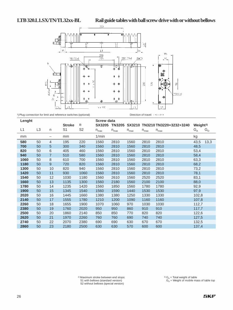
580 50 4 195 220 1560 2810 1560 2810 2810 43,5 13,3700 50 5 300 340 1560 2810 1560 2810 2810 48,5820 50 6 405 460 1560 2810 1560 2810 2810 53,4940 50 7 510 580 1560 2810 1560 2810 2810 58,41060 50 8 610 700 1560 2810 1560 2810 2810 63,31180 50 9 720 820 1560 2810 1560 2810 2810 68,21300 50 10 820 940 1560 2810 1560 2810 2810 73,21420 50 11 930 1060 1560 2810 1560 2810 2810 78,11540 50 12 1030 1180 1560 2610 1560 2520 2520 83,11660 50 13 1135 1300 1560 2180 1560 2100 2100 88,01780 50 14 1235 1420 1560 1850 1560 1780 1780 92,91900 50 15 1345 1540 1560 1590 1440 1530 1530 97,92020 50 16 1445 1660 1380 1380 1250 1330 1330 102,82140 50 17 1555 1780 1210 1200 1090 1160 1160 107,82260 50 18 1655 1900 1070 1060 970 1030 1030 112,72380 50 19 1760 2020 950 950 860 910 910 117,72500 50 20 1860 2140 850 850 770 820 820 122,62620 50 21 1970 2260 760 760 690 740 740 127,52740 50 22 2070 2380 690 690 630 670 670 132,52860 50 23 2180 2500 630 630 570 600 600 137,4
LTB 320.L1.SX/TN/TL32xx-BL Rail guide tables with ball screw drive with orwithout bellows
1) Plug connection for limit and reference switches (optional) Direction of travel: - <---> +
3) GA = Total weight of tableGO = Weight of mobile mass of table top
2) Maximum stroke between end stops:S1 with bellows (standard version)S2 without bellows (special version)

27
Lenght Screw dataStroke2) SX3205 TN3205 SX3210 TN3210 TN3220+3232+3240 Weight4)
L1 L3 n S nmax nmax nmax nmax nmax GA GO
mm – mm 1/min kg
580 50 4 220 1560 2810 1560 2810 2810 62,9 30,4700 50 5 340 1560 2810 1560 2810 2810 68,3820 50 6 460 1560 2810 1560 2810 2810 73,8940 50 7 580 1560 2810 1560 2810 2810 79,21060 50 8 700 1560 2810 1560 2810 2810 84,61180 50 9 820 1560 2810 1560 2810 2810 90,01300 50 10 940 1560 2810 1560 2810 2810 95,51420 50 11 1060 1560 2810 1560 2810 2810 100,91540 50 12 1180 1560 2610 1560 2520 2520 106,31660 50 13 1300 1560 2180 1560 2100 2100 111,71780 50 14 1420 1560 1850 1560 1780 1780 117,21900 50 15 1540 1560 1590 1440 1530 1530 122,62020 50 16 1660 1380 1380 1250 1330 1330 128,02140 50 17 1780 1210 1200 1090 1160 1160 133,52260 50 18 1900 1070 1060 970 1030 1030 138,92380 50 19 2020 950 950 860 910 910 144,32500 50 20 2140 850 850 770 820 820 149,72620 50 21 2260 760 760 690 740 740 155,22740 50 22 2380 690 690 630 670 670 160,62860 50 23 2500 630 630 570 600 600 166,0
LTB 320.L1.SX/TN/TL32xx-SC Rail guide tables with ball screw drive with steel cover
1) Plug connection for limit and reference switches (optional) Direction of travel: - <---> +
2) Maximum stroke between end stops 3) GA = Total weight of tableGO = Weight of mobile mass of table top

28
Lenght A32014 A33014 A340143) Stroke2) 4) Stroke2) 4) Stroke2) 4)
L1 L3 n GU L2 S1 S2 GO L2 S1 S2 GO L2 S1 S2 GO
mm – kg mm kg mm kg mm kg
580 50 4 30,4 280 260 290 15,3 320 225 250 18,7 410 140 160 23,8700 50 5 36,1 360 410 325 370 250 280820 50 6 41,9 465 530 435 490 350 400940 50 7 47,6 570 650 535 610 455 5201060 50 8 53,3 675 770 640 730 560 6401180 50 9 59,1 775 890 740 850 665 7601300 50 10 64,8 885 1010 850 970 765 8801420 50 11 70,5 985 1130 950 1090 875 10001540 50 12 76,3 1090 1250 1060 1210 975 11201660 50 13 82,0 1195 1370 1160 1330 1080 12401780 50 14 87,7 1300 1490 1265 1450 1185 13601900 50 15 93,5 1400 1610 1370 1570 1290 14802020 50 16 99,2 1510 1730 1475 1690 1390 16002140 50 17 104,9 1610 1850 1575 1810 1500 17202260 50 18 110,7 1720 1970 1685 1930 1600 18402380 50 19 116,4 1820 2090 1785 2050 1710 19602500 50 20 122,1 1925 2210 1890 2170 1810 20802620 50 21 127,9 2025 2330 1995 2290 1915 22002740 50 22 133,6 2135 2450 2100 2410 2015 23202860 50 23 139,3 2235 2570 2200 2530 2125 2440
LTB 320.L1.A3xxxx-BL Rail guide tables with linearmotordrive with orwithout bellows
1) only at size A33014 + A34014 A Cable output for motor and measuring system. Flat ribbon cable 20 x 6.3 mm Direction of travel: - <---> +
3) GU = Stationary mass of bottom part4) GO = Mobile mass of table top
2) Maximum stroke between end stops:S1 with bellows (standard version)S2 without bellows (special version)

29
Lenght A32014 A33014 A340143) Stroke2) 4) Stroke2) 4) Stroke2) 4)
L1 L3 n GU L2 S n4xL4 GO L2 S n4xL4 GO L2 S n4xL4 GO
mm – kg mm kg mm kg mm kg
580 50 4 32,6 280 290 3x75 22,3 320 250 3x87 26,8 410 160 4x88 34,1700 50 5 38,7 410 370 280820 50 6 44,9 530 490 400940 50 7 51,0 650 610 5201060 50 8 57,2 770 730 6401180 50 9 63,3 890 850 7601300 50 10 69,5 1010 970 8801420 50 11 75,6 1130 1090 10001540 50 12 81,8 1250 1210 11201660 50 13 87,9 1370 1330 12401780 50 14 94,1 1490 1450 13601900 50 15 100,2 1610 1570 14802020 50 16 106,4 1730 1690 16002140 50 17 112,5 1850 1810 17202260 50 18 118,7 1970 1930 18402380 50 19 124,8 2090 2050 19602500 50 20 130,9 2210 2170 20802620 50 21 137,1 2330 2290 22002740 50 22 143,2 2450 2410 23202860 50 23 149,4 2570 2530 2440
LTB 320.L1.A3xxxx-SC Rail guide tables with linear motor drive with steel cover
1) only at size A33014 + A34014 A Cable output for motor and measuring system. Flat ribbon cable 20 x 6.3 mm Direction of travel: - <---> +
4) GU = Stationary mass of bottom part5) GO = Mobile mass of table top
2) Maximum stroke between end stops

30
Lenght Screw datStroke 2) SX4005 TN4005 SX4010 TN4010 TN4020+4040Weight3)
L1 L3 n S1 S2 nmax nmax nmax nmax nmax GA GO
mm – mm 1/min kg
620 70 3 145 160 1250 2250 1250 2250 2250 77,0 25,2780 70 4 290 320 1250 2250 1250 2250 2250 87,7940 70 5 430 480 1250 2250 1250 2250 2250 98,41100 70 6 570 640 1250 2250 1250 2250 2250 109,11260 70 7 710 800 1250 2250 1250 2250 2250 119,81420 70 8 860 960 1250 2250 1250 2250 2250 130,51580 70 9 1000 1120 1250 2250 1250 2250 2250 141,21740 70 10 1140 1280 1250 2250 1250 2250 2250 151,91900 70 11 1280 1440 1250 2150 1250 1980 1980 162,62060 70 12 1425 1600 1250 1780 1250 1630 1630 173,32220 70 13 1565 1760 1250 1490 1250 1370 1370 184,02380 70 14 1705 1920 1250 1270 1180 1160 1160 194,72540 70 15 1845 2080 1090 1090 1010 1000 1000 205,42700 70 16 1990 2240 950 950 880 870 870 216,12860 70 17 2135 2400 840 830 770 760 760 226,8
LTB 400.L1.SX/TN/TL40xx-BL Rail guide tables with ball screw drive with orwithout bellows
1) Plug connection for limit and reference switches (optional) Direction of travel: - <---> +
3) GA = Total weight of tableGO = Weight of mobile mass of table top
2) Maximum stroke between end stops:S1 with bellows (standard version)S2 without bellows (special version)

31
Table precision:See page 8 for further information.P10P5P2P1
Covers:See page 8 for further information.BL with bellows- without coverSC with steel cover
Drive:Ball screw:See page 6 for further information.SH no preloadSX no preloadTN preloadedTL preloaded12 to 40 screw diameter05 to 40 screw leadLinear motor drive:See page 7 for further information.F Motor typeA Motor type2 - 3 Number of motor phases09 - 40 primary part length [cm]06 - 14 primary part width [cm]
Length of table:See dimension specifications150 to 2860 L1 Length of bottom part
Width of table:See dimension specifications110 to 400 Width of bottom part
Ordering details
For linear motor slides, the follo-wing additional details are required:
- Moving mass- Possibly applied additional forces- Maximum and minimum speeds;
maximum acceleration- Percentage duty cycle (description
of operating cycle)- Requirements of measuring system
such as signal period and accuracy- Required positioning resolution- Information on triggering
Please fill in the specification sheet onpage 35 and return it to us.
Type designation
LTB 320.1900.A33014-BL-P5

32
Application samples
Solder paste printer
Drive for a milling / drilling unit

33
Laser cutting
Laser welding

34
Possible application schemes
Fig. 1: Cross table X + Y Fig. 2: Gantry X + Y
Fig. 3: Gantry X1/X2 + Y Fig. 4: Gantry X1/X2 + Y1 + Y2
Fig. 5: Gantry X1/X2 + X3/X4 + Y1 + Y2 Fig. 6: Gantry X1/X2 + X3/X4 + Y1 + Y2 + Y3 + Y4

35
SKF Linear Motion + Precision TechnologiesProject Management - Positioning SystemsFax +49 (0) 62 26 / 92 03 12email [email protected]
1. Customer / customer address: ................................................................................................
............................................................................................................................................................................
2. Application: .............................................................................................................................................................................................................................
3. Number of axes in system: ..................................................................................................
4. Effective stroke / operating stroke [mm]: ....................................................................
5. Loads: additional moving mass [kg]:
additional force [N]:
direction of force [±X, ±Y, ±Z]:
6. Speed: maximum [m/s]:
minimum [m/s]:
7. Acceleration: maximum [m/s2]:
8. Mode of operation: duty cycle (ED) [%]:
length of one operating cycle [s]:
interval between two operating cycles [s]:
operating hours per year [h]:
9. Specification life: operating hours [h]:
10. Precision: straightness T [µm/S]:
positioning tolerance (absolute positioning accuracy) [µm]:
positioning variance Ps (repeating accuracy) [µm]:
positioning resolution [µm]:
11. Control: Components: only servo control � .................................................................................................
complete control unit � .................................................................................................
Positioning: linear path control � .................................................................................................
continuous path control � .................................................................................................
Interfaces: ..............................................................................................................................................................................
......................................................................................................................................................................................................
Options: .................................................................................................................................................................................
......................................................................................................................................................................................................
12. Environmental conditions: (contamination, interference fields, place of operation) ........................................................................
13. Accessories: (such as energy chain, cabling etc.) ..............................................................................................................................................
......................................................................................................................................................................................................
......................................................................................................................................................................................................
14. For multi-axial systems: arrangement of axes in accordance with drawings (see page 34).................................................
15. Remarks: ......................................................................................................................................................................................................
...............................................................................................................................................................................................................................................................
...............................................................................................................................................................................................................................................................
...............................................................................................................................................................................................................................................................
...............................................................................................................................................................................................................................................................
Filled in by / on:
X Y Z
.................... .................... ....................
.................... .................... ....................
.................... .................... ....................
.................... .................... ....................
.................... .................... ....................
.................... .................... ....................
.................... .................... ....................
.................... .................... ....................
.................... .................... ....................
.................... .................... ....................
.................... .................... ....................
.................... .................... ....................
.................... .................... ....................
.................... .................... ....................
.................... .................... ....................
.................... .................... ....................
.................... .................... ....................
Specification sheet for the selection of rail guide tables

36
SKF Sales companies
Australia
SKF AUSTRALIA PTY. LTDP. O. Box 301OAKLEIGH, Victoria 3166Phone: + 61 (3) 5 67 28 00Fax: + 61 (3) 5 67 28 88
Austria
SKF ÖSTERREICH AGPostfach 87A-2355 WIENER NEUDORFPhone: + 43 (22 36) 6 70 90Fax: + 43 (22 36) 6 70 92 20
Benelux
SKF MULTITEC BENELUX B. V.Kelvinbaan 16NL-3439 MT NIEUWEGEINPhone: + 31 306 029 029Fax: + 31 306 029 028Phone: (B) + 32 2 5024270Fax: (B) + 32 2 5027336
Canada
SKF CANADA LIMITED40 Executive CourtSCARBOROUGH, ONTARIOMIS 4 N 4Phone: + 1 (4 16) 2 99 12 20Fax: + 1 (4 16) 2 92 03 99
Czech Republic
SKF LOÎISKA A.S.P. O. Box 19U Mû‰tanského pivovaru 717004 PRAHA 7Phone: + 420 (0)2 66 19 71 11Fax: + 420 (0)2 66 71 04 15
Denmark
SKF MULTITECBramdrupskovvej 17DK-6000 KOLDINGPhone: + 45 - 65 92 77 77Phone: + 46 - 42 25 35 00Fax: + 45 - 65 92 74 77
Finland
SKF MULTITECPL 60FIN-02201 ESPOOPhone: + 3 58 94 52 97 54Fax: + 3 58 94 12 77 65
France
SKF EQUIPEMENTS30/32 Ave. Des Trois PeuplesF-78185 SAINT QUENTINYvelines CedexPhone: + 33 (1) 30 12 73 00Fax: + 33 (1) 30 12 69 09
Germany
SKF LINEARSYSTEME GMBHHans-Böckler-Straße 697424 SCHWEINFURTPhone: + 49 (97 21) 6 57 - 0Fax: + 49 (97 21) 6 57 - 111
Great Britain
SKF ENGINEERING PRODUCTS LTD.Sundon Park RoadLutonBEDFORDSHIRE LU3 3BLPhone: + 44 (15 82) 49 0049Fax: + 44 (15 82) 49 6574
Hong Kong
SKF CHINA LIMITEDUnit A 35/F. Manulife Tower169 Electric Road · North PointHONG KONGPhone: + 852 - 25 10 81 11Fax: + 852 - 25 10 73 68
Hungary
SKF SVÉD GOLYÓSCSAPÁGYRESZVENYTARSASAGCsata u. 25HU-2040 BUDAÖRSPhone: + 36 (23) 41 59 96Fax: + 36 (23) 41 59 28
Italy
SKF MULTITEC S.p. A.Corso Vittorio Emanuele II, 94I-10121 TORINOPhone: + 39 (011) 57 17 61Fax: + 39 (011) 5 71 76 33
Japan
SKF JAPAN LTD9-1 1-Chome, Shiba DaimonMinato - KuTOKYO 105Phone: + 81 3 3436 4129Fax: + 81 3 3578 1014
Norway
SKF MULTITEC A/SJerikoveien 141067 OSLON-1007 OSLO 10Phone: + 47 (2) 2 30 71 70Fax: + 47 (2) 2 30 28 14
PolandSKF CENTRALA HANLOWO-TECHNICZNA SP. ZO.O.ul. Pulawska 30302-785 WARSZAWAPhone: + 48 22 549 4700Fax: + 48 22 549 4701
Sweden
SKF MULTITEC ABEkslingan 3 · HELSINGBORGPostal address: Box 222 48S-25024 HELSINGBORGPhone: + 46 (42) 25 35 00Fax: + 46 (42) 25 35 45
Singapore
SKF SOUTH EAST ASIA &PACIFIC PTE. LTD.153 Gul Circle JurongSingapore 629610Postal Address:Jurong Point P. O. Box 445SINGAPORE 916415Phone: + 65 - 8 61 69 22Fax: + 65 - 8 61 10 11
Spain/Portugal
SKF PRODUCTOS INDUSTRIALES S.A.Apartado 769E-08080 BARCELONAPhone: + 34 (93) 3 77 99 77Fax: + 34 (93) 4 74 20 39/31 56
Switzerland
SKF (SCHWEIZ)Eschenstraße 5CH-8603 SCHWERZENBACHPhone: + 41 (1) 8 25 81 81Fax: + 41 (1) 8 25 82 82
USA
SKF MOTION TECHNOLOGIES1530 Valley Center ParkwayUSA-BETHLEHEM, PA 18017Phone: + 1 (610) 861 - 4800Fax: + 1 (610) 861 - 4811

Linear Motion
Linear Motion
http://www.linearmotion.skf.com
SKF Linear Motion offers a wide range of precision engineered linear motion components, units and systems.In addition to comprehensive product literature and software, SKF offers assistance from experienced linear motion engineers.Linear Motion has 3 product lines and a sales organisation based on 11 specialized sales companies located in Europe, Japan and in the USA.However the product availability as well as the product application is world-wide granted by the SKF Bearing international network.To get any other SKF address all over the world, please contact one of the companies below.
SKF Guiding Systems
AustriaLinear MotionSKF Österreich AGPhone: +43 22 36 6 7090Fax: +43 22 36 6 709220e-mail: [email protected]
BeneluxSKF Multitec Benelux B.V.Phone: +31 30 6029029Fax: +31 30 6029028Sales Office Belgium/Luxembourg:Phone: +32 2 5024270Fax: +32 2 5027336e-mail: [email protected]
FranceSKF EquipementsPhone: +33 1 30 12 73 00Fax: +33 1 30 12 69 09e-mail: [email protected]
GermanySKF Linearsysteme GmbHPhone: +49 9721 657-0Fax: +49 9721 657-111e-mail: [email protected]
ItalyMultitec SKF Industrie S.p.A.Phone: +39 11 57 17 61Fax: +39 11 5 71 76 33e-mail: [email protected]
JapanSKF Japan Ltd.Phone: +81 3 3436 4129Fax: +81 3 3578 1014e-mail: [email protected]
SpainSKF Productos Industriales S.APhone: +34 93 377 99 77
+34 93 377 99 07Fax: +34 93 474 20 39/31 56e-mail: [email protected]
SwitzerlandLinear Motion & Precision TechnologiesPhone: +41 1 825 81 81Fax: +41 1 825 82 82e-mail: [email protected]
Sweden/Denmark/Finland/NorwaySKF Multitec SwedenPhone: +46 42 25 35 00Fax: +46 42 25 35 45/46
Sales Office DenmarkPhone: +45 65 92 77 77Fax: +45 65 92 74 77
Sales Office FinlandPhone: +358 94 52 97 52Fax: +358 94 12 77 65
Sales Office NorwayPhone: +47 22 30 71 70Fax: +47 22 30 28 14e-mail: [email protected]
United KingdomSKF Engineering Products Ltd.Phone: +44 1582 490049Fax: +44 1582 496574e-mail. [email protected]
USASKF Motion TechnologiesPhone: +1 610 861-4800Fax: +1 610 861-4811e-mail: [email protected]
SKF Ball & Roller Screws SKF Actuators
®