
SKELETON - Web viewTest description language, model-based testing, test description, test...
46
ETSI TR 203 119 V1.1.1 (2016-04) Methods for Testing and Specification (MTS); The Test Description Language (TDL); Reference Implementation << TECHNICAL REPORT
Transcript of SKELETON - Web viewTest description language, model-based testing, test description, test...

ETSI TR 203 119 V1.1.1 (2016-04)
Methods for Testing and Specification (MTS);The Test Description Language (TDL);
Reference Implementation
<<
TECHNICAL REPORT

Reference'DTR/MTS-203119REFv1.1.1'
KeywordsTest description language, model-based testing,
test description, test purpose, test model
ETSI
650 Route des LuciolesF-06921 Sophia Antipolis Cedex - FRANCE
Tel.: +33 4 92 94 42 00 Fax: +33 4 93 65 47 16
Siret N° 348 623 562 00017 - NAF 742 CAssociation à but non lucratif enregistrée à laSous-préfecture de Grasse (06) N° 7803/88
Important notice
The present document can be downloaded from:http://www.etsi.org/standards-search
The present document may be made available in electronic versions and/or in print. The content of any electronic and/or print versions of the present document shall not be modified without the prior written authorization of ETSI. In case of any
existing or perceived difference in contents between such versions and/or in print, the only prevailing document is the print of the Portable Document Format (PDF) version kept on a specific network drive within ETSI Secretariat.
Users of the present document should be aware that the document may be subject to revision or change of status. Information on the current status of this and other ETSI documents is available at
http://portal.etsi.org/tb/status/status.asp
If you find errors in the present document, please send your comment to one of the following services:https://portal.etsi.org/People/CommiteeSupportStaff.aspx
Copyright Notification
No part may be reproduced or utilized in any form or by any means, electronic or mechanical, including photocopying and microfilm except as authorized by written permission of ETSI.
The content of the PDF version shall not be modified without the written authorization of ETSI.The copyright and the foregoing restriction extend to reproduction in all media.
© European Telecommunications Standards Institute 2016.All rights reserved.
DECTTM, PLUGTESTSTM, UMTSTM and the ETSI logo are Trade Marks of ETSI registered for the benefit of its Members.3GPPTM and LTE™ are Trade Marks of ETSI registered for the benefit of its Members and
of the 3GPP Organizational Partners.GSM® and the GSM logo are Trade Marks registered and owned by the GSM Association.
ETSI
ETSI TR 203 119 V1.1.1 (2016-04)2

ContentsIntellectual Property Rights.................................................................................................................................4
Foreword.............................................................................................................................................................4
Modal verbs terminology....................................................................................................................................4
1 Scope.........................................................................................................................................................5
2 References.................................................................................................................................................52.1 Normative references...........................................................................................................................................52.2 Informative references.........................................................................................................................................5
3 Definitions and abbreviations...................................................................................................................63.1 Definitions...........................................................................................................................................................63.2 Abbreviations.......................................................................................................................................................6
4 Basic Principles.........................................................................................................................................74.1 Introduction.........................................................................................................................................................74.2 Implementation Scope.........................................................................................................................................74.3 Document Structure.............................................................................................................................................8
5 Graphical Representation Viewer.............................................................................................................85.1 Scope and Requirements.....................................................................................................................................85.2 Architecture and Technology Foundation...........................................................................................................95.2.1 Diagram Viewer.............................................................................................................................................95.2.2 Structured Test Objective Representation......................................................................................................95.3 Implemented Facilities.......................................................................................................................................105.3.1 Creating Models...........................................................................................................................................105.3.2 Viewing Models...........................................................................................................................................145.3.3 Exporting Structured Test Objectives..........................................................................................................225.3.4 Validating Models........................................................................................................................................245.4 Usage Instructions.............................................................................................................................................245.4.1 Development Environment..........................................................................................................................245.4.2 End-user Insturctions...................................................................................................................................25
6 UML Profile Editor.................................................................................................................................266.1 Architecture and Technology Foundation.........................................................................................................266.2 Implemented Facilities..................................................................................................................................................276.2.1 Applying the Profile..................................................................................................................................................276.2.2 Hints for the Transforming UP4TDL Models into TDL Models..............................................................................276.2.3 Editing models with the Model Explorer...................................................................................................................286.2.4 Editing models with TDL-specific properties from the 'TDL property view'...........................................................286.2.5 Editing models with TDL-specific diagrams.............................................................................................................29
History...............................................................................................................................................................33
ETSI
ETSI TR 203 119 V1.1.1 (2016-04)3

Intellectual Property RightsIPRs essential or potentially essential to the present document may have been declared to ETSI. The information pertaining to these essential IPRs, if any, is publicly available for ETSI members and non-members, and can be found in ETSI SR 000 314: "Intellectual Property Rights (IPRs); Essential, or potentially Essential, IPRs notified to ETSI in respect of ETSI standards", which is available from the ETSI Secretariat. Latest updates are available on the ETSI Web server (http://ipr.etsi.org).
Pursuant to the ETSI IPR Policy, no investigation, including IPR searches, has been carried out by ETSI. No guarantee can be given as to the existence of other IPRs not referenced in ETSI SR 000 314 (or the updates on the ETSI Web server) which are, or may be, or may become, essential to the present document.
ForewordThis final draft Technical Report (TR) has been produced by the ETSI Technical Committee Methods for Testing and Specification (MTS) and is now submitted for the ETSI standards Membership Approval Procedure.
The present document is complementary to a multi-part deliverable covering the Test Description Language as identified below:
Part 1: "Abstract Syntax and Associated Semantics";
Part 2: "Graphical Syntax";
Part 3: "Exchange Format";
Part 4: "Structured Test Objective Specification (Extension)".
Modal verbs terminologyIn the present document "shall", "shall not", "should", "should not", "may", "need not", "will", "will not", "can" and "cannot" are to be interpreted as described in clause 3.2 of the ETSI Drafting Rules (Verbal forms for the expression of provisions).
"must" and "must not" are NOT allowed in ETSI deliverables except when used in direct citation.
ETSI
ETSI TR 203 119 V1.1.1 (2016-04)4

1 ScopeThe present document summarises technical aspects related the reference implementation of TDL comprising an implementation of the TDL meta-model, a viewer for the graphical representation format of TDL, different options for creating and manipulating models, facilities for the serialisation and deserialization of TDL models in the form of XML documents according to the exchange format for TDL, as well as facilities for checking the semantic validity of models according to the constraints specified in the TDL meta-model. The present document also summarises technical aspects related to the implementation of the UML profile for TDL and an editor supporting the creation and manipulation of UML models applying the UML profile for TDL.
2 References2.1 Normative referencesReferences are either specific (identified by date of publication and/or edition number or version number) or non-specific. For specific references, only the cited version applies. For non-specific references, the latest version of the referenced document (including any amendments) applies.
Referenced documents which are not found to be publicly available in the expected location might be found at http://docbox.etsi.org/Reference.
NOTE: While any hyperlinks included in this clause were valid at the time of publication, ETSI cannot guarantee their long term validity.
The following referenced documents are necessary for the application of the present document.
[1] ETSI ES 203 119-1 (V1.3.0): "Methods for Testing and Specification (MTS); The Test Description Language (TDL); Part 1: Abstract Syntax and Associated Semantics".
[2] ETSI ES 203 119-2 (V1.2.0): "Methods for Testing and Specification (MTS); The Test Description Language (TDL); Part 2: Graphical Syntax".
[3] ETSI ES 203 119-3 (V1.2.0): "Methods for Testing and Specification (MTS); The Test Description Language (TDL); Part 3: Exchange Format".
[4] ETSI ES 203 119-4 (V1.2.0): "Methods for Testing and Specification (MTS); The Test Description Language (TDL); Part 4: Structured Test Objective Specification (Extension)".
2.2 Informative referencesReferences are either specific (identified by date of publication and/or edition number or version number) or non-specific. For specific references, only the cited version applies. For non-specific references, the latest version of the referenced document (including any amendments) applies.
NOTE: While any hyperlinks included in this clause were valid at the time of publication, ETSI cannot guarantee their long term validity.
The following referenced documents are not necessary for the application of the present document but they assist the user with regard to a particular subject area.
[i.1] Eclipse Foundation: Eclipse IDE Website (last visited 30.03.2016).
NOTE: Available at https://eclipse.org.
[i.2] Eclipse Foundation: Eclipse Xtext Website (last visited 30.03.2016).
NOTE: Available at https://eclipse.org/Xtext/index.html.
[i.3] Eclipse Foundation: Eclipse Sirius Website (last visited 30.03.2016).
NOTE: Available at http://www.eclipse.org/sirius/index.html.
ETSI
ETSI TR 203 119 V1.1.1 (2016-04)5

[i.4] Eclipse Foundation: Eclipse Modeling Framework (EMF) Website (last visited 30.03.2016).
NOTE: Available at http://www.eclipse.org/modeling/emf/.
[i.5] Eclipse Foundation: Eclipse Papyrus Modeling Environment Website (last visited 30.03.2016).
NOTE: Available at https://www.eclipse.org/papyrus/.
[i.6] Eclipse Foundation: UML Profiles Repository Website (last visited 30.03.2016).
NOTE: Available at https://projects.eclipse.org/projects/modeling.upr.
[i.7] Eclipse Foundation: Graphical Modeling Framework (GMF) Website (last visited 30.03.2016).
NOTE: Available at http://www.eclipse.org/modeling/gmp/.
[i.8] "Object Constraint LanguageTM (OMG OCL), Version 2.4", formal/2014-02-03.
NOTE: Available at http://www.omg.org/spec/OCL/2.4/.
[i.9] Eclipse Foundation: Eclipse OCL Website (last visited 30.03.2016).
NOTE: Available at https://projects.eclipse.org/projects/modeling.mdt.ocl.
[i.10] Plutext Pty Ltd: Docx4j Website (last visited 30.03.2016).
NOTE: Available at http://www.docx4java.org/trac/docx4j.
[i.11] "OMG XML Metadata Interchange (XMI) Specification", Version 2.4.2, formal/2014-04-04.
NOTE: Available at http://www.omg.org/spec/MOF/2.4.2/.
[i.12] Eclipse Foundation: Epsilon Validation Language (EVL) Website (last visited 30.03.2016).
NOTE: Available at http://www.eclipse.org/epsilon/doc/evl/.
3 Definitions and abbreviations3.1 DefinitionsFor the purposes of the present document, the following terms and definitions apply:
abstract syntax: graph structure representing a TDL specification in an independent form of any particular encoding
concrete syntax: particular representation of a TDL specification, encoded in a textual, graphical, tabular or any other format suitable for the users of this language
meta-model: modelling elements representing the abstract syntax of a language
system under test (SUT): role of a component within a test configuration whose behaviour is validated when executing a test description
TDL model: instance of the TDL meta-model
TDL specification: representation of a TDL model given in a concrete syntax
3.2 AbbreviationsFor the purposes of the present document, the following abbreviations apply:
API Application Programming InterfaceEBNF Extended Backus-Naur FormEMF Eclipse Modelling FrameworkEVL Epsilon Validation LanguageGMF Graphical Modelling Framework
ETSI
ETSI TR 203 119 V1.1.1 (2016-04)6

MBT Model-Based TestingMOF Meta-Object FacilityOCL Object Constraint LanguageOMG Object Management Group®SUT System Under TestTDL Test Description LanguageTTCN-3 Testing and Test Control Notation version 3UML Unified Modelling LanguageURI Unified Resource IdentifierXML eXtensible Markup LanguageXMI XML Metadata Interchange
4 Basic Principles4.1 IntroductionTo accelerate the adoption of TDL, a reference implementation of TDL is provided in order to lower the barrier to entry for both users and tool vendors in getting started with using TDL. The reference implementation comprises graphical and textual editors, as well as validation facilities. In addition, an implementation of the UML profile for TDL and supporting editing facilities seek to enable its application in UML-based working environments and model-based testing approaches.
4.2 Implementation ScopeThe implementation scope includes a graphical viewer according to ES 203 119-2 [2] based on the Eclipse platform [i.1] and related technologies, covering essential constructs related to test configurations and test behaviour specification. For creating and manipulating models, a textual editor for ES 203 119-1 [1], Annex B is implemented based on the Eclipse platform and related technologies. The applicability of general purpose model editing facilities provided by the Eclipse platform and related technologies is discussed.
For tools that need to import and export TDL models according to ES 203 119-3 [3], corresponding facilities are implemented based on the Eclipse platform and related technologies. These facilities can be used to transform textual representations based on ES 203 119-1 into XMI [i.11] serialisations according to ES 203 119-3 and can be integrated in custom tooling that builds on the Eclipse platform.
An implementation of ES 203 119-4 [4] includes a dedicated textual editor for structured test objectives, which can be integrated in the textual editor for TDL. The implementation also includes facilities for exporting structured test objectives to Word documents using customisable tabular templates.
An implementation of the UML profile for TDL includes a specification of the TDL UML profile abstract syntax according to the mapping from the TDL meta-model to TDL stereotypes and UML meta-classes in ES 203 119-1 Annex C. It is integrated with the open source UML modelling environment Eclipse Papyrus [i.5] as an open TDL UML profile reference implementation platform. It will be published on the open source "Eclipse UML Profiles Repository" project [i.6].
ETSI
ETSI TR 203 119 V1.1.1 (2016-04)7

Figure 4.1: TDL tool infrastructure
An overview of the context of the reference implementation is shown in Figure 4.4.1. The TDL exchange format specified in ES 203 119-3 serves as a bridge between the different tool components. Textual editors enable the creation and manipulation of TDL models. The graphical viewer is used to visualise TDL models as diagrams. Documentation generation, in particular for structured test objectives, can be plugged in to produce Word documents for presenting parts of a TDL model in a format suitable for standardisation documents.
The complete implementation will be published on an open-source portal serving as a central hub for the TDL community.
4.3 Document StructureThe present document contains two main technical clauses focusing on relevant technical details. The Graphical Representation Viewer implementing ES 203 119-2, as well as related facilities implementing ES 203 119-1, ES 203 119-3 and ES 203 119-4 are described in Clause 5. The UML Profile Editor implementing Annex C of ES 203 119-1 is described in Clause 6.
5 Graphical Representation Viewer5.1 Scope and RequirementsTDL graphical viewer implementation has two major requirements. The main objective is to provide means to visualize TDL models according to the graphical notation. The second objective is to facilitate layout of diagrams in a way that is suitable for documentation. For the second purpose, it is essential to provide graphical editing capabilities. Although often provided by modelling frameworks, the ability to graphically edit the underlying models (that is, to create new elements and set their properties) is not considered relevant for this implementation.
Eclipse provides several graphical modelling tools to help build editors. Sirius [i.3] was chosen for its declarative approach that provides separation between meta-model mappings and implementations of graphical elements. With the existence of predefined common graphical elements such as containers and connectors, the effort of implementing graphical editor with custom syntax in Sirius is only spent on the parts that diverge from those common elements.
Another area that requires custom implementation is the layout of graphical elements. This covers both the absolute placement of nodes on the diagram as well as the size and internal contents of each node. Due to rather hierarchical nature of the TDL graphical syntax, several additional base graphical elements shall be introduced. Some peculiar limitations of Sirius have also been identified prior to the implementation, which also need appropriate workarounds. The goal of implementing diagram layout is to automate diagram creation to the extent that the sizes and contents of graphical elements are adjusted by layout algorithms while the absolute placement of diagram elements is solved by
ETSI
ETSI TR 203 119 V1.1.1 (2016-04)8

Eclipse platform
GMF
Diagram specification
TDL (XF)
DiagramSirius
EMF
TDL viewer Image
TDL Ecore
using built in layout implementations. This will guarantee minimal user interaction with diagram editor for achieving desired layouts.
Diagram export for documentation purposes is provided by the framework. The viewer implementation will add complimentary export to Word document format.
Due to the peculiarities and intended use of structured test objectives, it was determined that instead of graphical shapes that can be exported as images, the graphical representation shall be realised as tables exported in a Word document according to user-defined templates. These tables can then be manipulated further as necessary to fit in within an existing document.
5.2 Architecture and Technology Foundation5.2.1 Diagram ViewerTDL viewer is built on Eclipse platform to benefit from its wide range of modelling tools. The main Eclipse projects that are used as basis for this implementation are shown in Figure 5.2.1. Sirius is a technology that allows declarative creation of graphical editors that work with EMF models. It uses GMF [i.7] to create visual diagram elements and link those to model objects. Model management and serialization is done by EMF [i.4].
NOTE: Components with grey background are part of the implementation that is covered by current document.
Figure 5.2.1: Dependencies and data flows of TDL viewer
Every EMF model is based on a meta-model that is defined in terms of meta-modelling system named Ecore. TDL meta-model in UML format was converted to Ecore meta-model (TDL Ecore) using Papyrus UML and EMF facilities. Furthermore, Java code for the TDL meta-model was generated based on the TDL meta-model.
Sirius creates diagram editors by interpreting diagram specification files. These files contain TDL meta-model references in the form of Java or OCL [i.8] queries. OCL support is provided by the Eclipse OCL project [i.9], Java queries are references to classes that are part of the TDL viewer source code. Diagram specifications also contain definitions of Sirius specific styles that are applied to model objects when rendering them on diagrams. Since the TDL viewer requires customized shapes, it has dependencies on both the Sirius API and the Eclipse GMF. Several extensions to GMF classes have been implemented in Sirius in order to configure shapes according to the customized styles. GMF facilities are then used to export diagrams as images.
Some of the labels in the graphical shapes, in particular labels related to data specification and data use have a complex structure. For their realisation, facilities provided by Xtext [i.2] are used to serialize model fragments related to data use as text according to an annotated EBNF grammar derived from the formal label specifications in ES 203 119-2.
5.2.2 Structured Test Objective RepresentationStructured test objectives are exported as tables in a Word document according to user-defined templates. The export relies on facilities provided by Xtext as well as the Docx4j library [i.10] providing API for manipulating Word
ETSI
ETSI TR 203 119 V1.1.1 (2016-04)9

documents. The exporting facilities take a Word document containing one or more templates in the form of tables with placeholders and a TDL model containing one or more structured test objectives as input. The user shall provide the name of the desired template as an additional input. For every structured test objective, the selected template is copied into a new empty document and the placeholders are replaced by the content serialised from the corresponding TDL element according to the Xtext mappings in a similar manner as the labels for the diagram viewer. The representation process is sketched on Figure 5.2.2. The generated tables in the new Word document can be further manipulated or merged into an existing document containing additional information. Additional templates may be defined by users to suit specific needs.
Figure 5.2.2: Structured test objective representation process
5.3 Implemented Facilities5.3.1 Creating ModelsOverview
Model instances are the primary artefacts for TDL. They carry the semantic information. In a modelling environment there are various means for creating, viewing, and manipulating model instances of a particular meta-model. Comprehensive modelling environments typically provide generic model facilities that enable working with model instances of arbitrary meta-models, provided the meta-model is known. Generic model facilities provide sufficient capabilities for performing basic tasks on model instances. However, due to their generic nature, they are cumbersome to work with, lack of support for certain features that are not expressed in the meta-model directly (unless customised), and do not provide domain-specific features such as syntactical customisation beyond basic adaptations.
Custom syntax implementations address some of the shortcomings of generic model editors. Such implementations enable the specification of a customised representation of a model instance in a format that is tailored to a specific group of users. There may be multiple custom syntax implementations mapped to the same meta-model, serving different stakeholders or even different purposes for the same stakeholder. Custom syntax implementations may cover only a subset of the meta-model, restricting the access to certain features that are not relevant for specific stakeholders
ETSI
ETSI TR 203 119 V1.1.1 (2016-04)10

or purposes. Modelling environments provide platforms for the realisation of custom syntax implementations. Custom syntax implementations may rely on secondary artefacts that store the concrete representation of the TDL model instance.
TDL model instances may be produced automatically by tools. The exchange format for TDL enables the interoperability of tools producing model instances and tools for manipulating model instances.
Generic Model Editors
The EMF provides facilities for generating basic tree editors for a given meta-model, which can then be customised to an extent while still remaining within the tree editor paradigm. In addition, the EMF also provides generic reflective model editors which provide quick access to model instances of any meta-model. An example of such an editor for TDL is shown in Figure 5.3.1. The example includes a tree-based editor for manipulating the overall structure of a model on top and a detailed property view for manipulating individual properties on the bottom.Extensions to the EMF such as MoDisco include additional generic facilities such as the MoDisco model browser which provides faceted browsing and editing of model instances. Faceted browsing provides filtering by type, as well as deep navigation across references. In addition, MoDisco also includes tabular views on different parts of the model for a quick overview across multiple dimensions. An example for a TDL model is illustrated in Figure 5.3.2. The example includes a faceted browser on the top for navigating and manipulating the overall structure of a model, as well as individual properties of model elements. On the left side of the faceted browser, model elements can be filtered by type. Below the faceted browser, a tabular viewer provides more compact representation of multiple model elements at the same level in a model tree, such as the behaviour elements of a block. The property view on the bottom part of the example still allows the manipulation of properties of selected model elements.
ETSI
ETSI TR 203 119 V1.1.1 (2016-04)11

Figure 5.3.1: Example of reflective model editor
ETSI
ETSI TR 203 119 V1.1.1 (2016-04)12

Figure 5.3.2: Example of MoDisco facetted model browser
Textual Editor
Xtext provides facilities for the automatic generation of a default textual syntax closely resembling the structure of the meta-model. It serves as the base for further refinements resulting in customised syntax definitions. Due to it being automatically generated, it is very similar in structure to the meta-model. As a consequence, it is also rather cumbersome to write actual test descriptions in the default syntax notation.
The reference implementation includes a customised textual syntax that implements the example syntax from Annex B of ES 203 119-1. Apart from the grammar specification, it also includes further customisations in the scoping and linking facilities for handling gate references, as well as enhanced semantic syntax highlighting which provides customisable styles for identifiers based on their type and usage. An example of the customized editor is shown in Figure 5.3.3. It features a textual representation of a test description as well as linked tree-based editor showing the
ETSI
ETSI TR 203 119 V1.1.1 (2016-04)13

same model instance in the tree-based paradigm. Current version of the grammar specification and the additional customisations can be found in Annex A of this document as part of the 'org.etsi.mts.tdl.TDLan2*' projects.
Figure 5.3.3: Example of customised textual editor for TDL
Similar to the editor for TDL, the reference implementation also includes a customised textual syntax that is tailored for the specification of structured test objectives. It implements the example syntax from Annex B of ES 203 119-4. It also includes further customisations in the scoping and linking facilities for handling gate references, as well as enhanced semantic syntax highlighting, in a similar manner as the editor for TDL. An example of the customized editor is shown in Figure 5.3.4. It features a textual representation of a structured test objective. Current version of the grammar specification and the additional customisations can be found in Annex A of this document as part of the 'org.etsi.mts.tdl.TPLan2*' projects.
Associated tooling provides means for the transformation between different syntax notations and model representations. Model instances in one notation can be transformed automatically into XMI representations and/or other textual or graphical syntax representations. This tooling integrates the APIs from different platforms for task specific automation. A current version of this tooling and detailed technical information can be found in Annex A as part of the 'org.etsi.mts.tdl.tools.*' projects.
ETSI
ETSI TR 203 119 V1.1.1 (2016-04)14

Figure 5.3.4: Example of customised textual editor for structured test objectives
Import and Export
The TDL reference implementation relies largely on the import and export facilities provided by the EMF. By default, the EMF does not activate the GUID support for XMI which is prescribed in ES 203 119-3. The TDL meta-model implementation needs to be adapted to activate the GUID support for model elements. The necessary adaptation involves selecting the correct resource type (XMI) in the generator model and activating the GUID support by overriding the corresponding method in the TDL resource implementation. The relevant modifications can be found in the 'org.etsi.mts.tdl.model' project within Annex A.
5.3.2 Viewing ModelsPrinciples of building model diagrams
The GMF framework that TDL viewer is built upon follows the Model-View-Controller architecture. The model is an instance of TDL meta-model. The view is comprised of the shapes displayed on the diagram. The controller takes care of creating figures based on model objects and their associations: cross-references and containments. In GMF, controllers are called 'editparts'.
The major part of the diagram viewer implementation consists of defining the corresponding 'editparts'. In case of Sirius, these are not implemented directly but rather defined in terms of mappings. A mapping is a relation between a certain model object and a shape. Sirius interprets each mapping and uses appropriate 'editpart' as a controller providing mapping configuration data.
Mappings can be defined as nodes, edges, or containers (and some additional items specific to sequence diagrams). Each mapping includes a reference to the meta-class of the model object that it applies to as well as the query that is used to lookup objects from the model based on the current context object. Similar to models and diagrams, mappings are also hierarchical. Edge mappings shall also define the queries that determine the corresponding shapes its endpoints shall connect to.
ETSI
ETSI TR 203 119 V1.1.1 (2016-04)15

Sirius diagrams
Sirius provides several diagram kinds that can be configured by providing diagram-specific model-object mappings. For TDL, the generic diagram and the sequence diagram are of particular interest.
Generic diagrams contain nodes and connections between the nodes with no specific constraints on their layout. Composite nodes containing other nodes are also supported, but only a few limited layout options are available for inner node placement: free-form and table (lines of text).
Sequence diagrams contain vertical parallel lines known as lifelines. Lifelines have headers with labels. Nodes and connectors between the lifelines – the fragments – are laid out as a horizontal stack. Nodes may cover any number of lifelines, connectors may only be drawn between two lifelines. Composite nodes containing sub-fragments (called combined fragments) are also supported.
Sirius editors are defined in configuration files known as viewpoint specifications. The TDL viewpoint specification defines a single viewpoint that contains two diagram descriptions named "TDL Behaviour" and "Generic TDL".
TDL Behaviour is a sequence diagram description. The root object of such diagrams is an instance of 'TestDescription'. The diagram description also defines the visual order of elements both horizontally and vertically. The vertical ordering contains behaviours recursively included in the 'TestDescription' as they occur semantically. The horizontal ordering contains 'GateReference's that are defined in the 'TestConfiguration' associated with the diagram’s 'TestDescription' instance.
Generic TDL is a generic diagram description. The root object of such diagrams is an instance of 'Package'. There is no predefined order of objects defined for this diagram kind.
Sirius diagram customization
The Sirius diagram specification model does not provide enough flexibility in terms of configuring all possible layouts required by the TDL graphical syntax. The diagrams are rendered by interpreting predefined configuration elements that don’t have any extension mechanisms built in. Thus, some simple and composite figures need to be customized at a lower level.
The Sirius diagram rendering is built on top of the GMF runtime. Thus, it is possible to customize Sirius diagrams by means of extension points provided by GMF. The 'org.eclipse.gmf.runtime.diagram.ui.editpartProviders' extension point allows the replacement of default Sirius 'editparts' with customized 'editparts' dynamically, depending on which model object is being rendered, and depending on which diagram it is being rendered on. Classes defined in the extensions use mapping identifiers from the diagram specification to decide whether and which custom 'editparts' should be provided for the rendering of a diagram. All other mappings will rely on the default 'editparts' provided by the Sirius implementation.
Implemented EditParts
All of the 'editpart' implementations are located in the 'org.etsi.mts.tdl.graphical.sirius.part' package.
The 'MultipartContainerCompartmentEditPart' extends GMF’s 'ListCompartmentEditPart'. This class adds grid layout that allows contained shapes to fill the available area within the container. It also removes all borders from contained shapes in order to get rid of shadows and places horizontal lines between the contained shapes instead. Lastly, it removes the ability of being dragged and selected from the contained shapes in order to facilitate moving the whole compartment shape as one. The mapping that uses this 'editpart' shall be a container.
Figure 5.3.5: Example of 'MultipartContainerCompartmentEditPart'
ETSI
ETSI TR 203 119 V1.1.1 (2016-04)16

The 'NodeListWithHeaderEditPart' extends the 'AbstractDiagramListEditPart' from the Sirius API. It is intended to be used as within a 'MultipartContainerCompartmentEditPart' and provides functionality that allows the container to control its drag and selection handling. It removes all line borders from the contained shapes and replaces the borders with margins. The mapping that uses this 'editpart' shall be a container with list presentation style. The first label of the figure is the label of that container’s style. The children of that mapping shall be nodes with square style.
Figure 5.3.6: Example of 'NodeListWithHeaderEditPart'
The 'TopLevelNodeListWithHeaderEditPart' extends the 'NodeListWithHeaderEditPart' and adds the ability to be included directly on the diagram or inside a container with free-form presentation style. It also fixes a bug in the 'AbstractDiagramElementContainerEditPart.reInitFigure()' method.
Figure 5.3.7: Example of 'NodeListWithHeaderEditPart'
The 'EditPartConfiguration' is used to specify additional style and layout properties supported by some custom 'editparts'. It is used, for example, to draw double border for specified edit parts using a 'TwoLineMarginBorder'.
Figure 5.3.8: Example of 'TopLevelImageNodeListWithHeaderEditPart'
The 'NodeContainerEditPart' extends the 'AbstractDiagramContainerEditPart' provided by the Sirius API. The default container is modified by disabling standalone selection and dragging and delegating those functions to the parent. All borders are removed from the shape. It is intended to be used as a child of 'MultipartContainerCompartmentEditPart'.
ETSI
ETSI TR 203 119 V1.1.1 (2016-04)17

Figure 5.3.9: Example of 'NodeContainerEditPart'
The 'InteractionUseConfiguringEditPart' extends the 'AbstractNotSelectableShapeNodeEditPart' provided by the Sirius API. The class modifies the default interaction use shape by setting custom layout to it. The custom layout stretches the container's children to fill the available vertical space and leaves sufficient margin to the top for the label of the container. If the interaction use mapping has image style then the image background is made opaque.
This class shall be mapped to (an abstract) sub-mapping of interaction use. That mapping does not need to have a style as it will not be visible. The first label of the interaction use is the label of the container. The rest of the labels shall be sub-nodes with square styles.
Figure 5.3.10: Example of 'InteractionUseConfiguringEditPart'
The 'MultiPartLabelEditPart' extends the 'TopLevelNodeListWithHeaderEditPart' and adds the ability to place labels horizontally in a row. This allows mappings that define different fonts for different parts of labels.
Figure 5.3.11: Example of 'MultiPartLabelEditPart'
The 'CombinedFragmentLabelEditPart' extends the 'MultiPartLabelEditPart' to inherit support for mixed font labels. It overrides the default layout behaviour via a 'LayoutListener' from the 'Draw2d' API and places the shape always to the upper right corner of a combined fragment block.
ETSI
ETSI TR 203 119 V1.1.1 (2016-04)18

Figure 2: Example of 'CombinedFragmentLabelEditPart'
The 'InteractionDecoratorProvider' is contributed via the 'org.eclipse.gmf.runtime.diagram.ui.decoratorProviders' extension point in order to draw special rotatable shapes at the ends of connectors. This class is configured to work specifically with 'Interaction's.
Figure 3: Example of 'InteractionDecoratorProvider'
Implemented layouts
All layout implementations are located in the 'org.etsi.mts.tdl.graphical.sirius.layout' package.
The 'SequenceDiagramFreeformLayoutProvider' overrides the default placement of elements on the diagram layer. It also fixes the layout of shapes modified by the 'InteractionUseConfiguringEditPart' that would otherwise be cropped to the default size and would not trigger the layout of contents on container resize. It is contributed via the 'org.eclipse.sirius.diagram.ui.layoutProvider' extension point and its use is triggered by the arrange command.
Figure 5.3.14: Example of custom figure placement: node with attachment
Figure 4: Example of custom figure placement: under-lapping container
The layout customizations are implemented via the diagram 'arrange' mechanism, which is normally triggered only when the user invokes the 'arrange' command. Additional triggers are implemented in order to facilitate the automatic diagram creation upon user creating and updating the model. The 'RefreshExtensionProvider' is contributed via the 'org.eclipse.sirius.refreshExtensionProvider' extension point. It invokes the 'arrange' command when model is modified and subsequently reloaded into the diagram editor. The 'LayoutEditPolicyProvider' is contributed via 'org.eclipse.gmf.runtime.diagram.ui.editpolicyProviders' extension point and it invokes the arrange command when a 'GateReference' or 'ComponentInstance' shape is moved by the user in order to keep the under-lapping shape properly aligned.
Viewer specific meta-model
The Sirius sequence diagram configuration sets implicit requirements on the structure of the meta-model that is used in mapping definitions. The TDL meta-model does not comply with these requirements in all cases. For example, the mappings of combined fragments tend to fail at runtime when the begin and end occurrence objects (as understood by
ETSI
ETSI TR 203 119 V1.1.1 (2016-04)19

Sirius) are the same. Since TDL does not define occurrences at all, some adaptation is needed to provide these occurrence objects. Sirius and the underlying framework require that model objects used in diagrams are defined by meta-model. Extending the TDL meta-model with pure fabrications, just to facilitate viewer implementations, would be a bad practice. Therefore, a separate domain-agnostic meta-model was created for this purpose.
The meta-model named 'tdlviewer' is defined in the 'extension.ecore' file and is registered as dynamic. This means that the meta-model may be used reflectively without any code generation (which is a standard practice with meta-model implementations in EMF). The 'tdlviewer' contains a single meta-class 'End' with a single attribute 'begin'. The 'begin' holds a reference to the model object which this instance of 'End' is paired with. The object itself is used as the begin occurrence in the mappings. The creation of virtual end objects is implemented in the 'org.etsi.mts.tdl.graphical.extensions.BehaviorProvider' class.
Label serialisation
Some of the labels in ES 203 119-2 are particularly complex, especially the labels related to 'DataUse'. Mappings for such labels in the diagrams are realised by means of Xtext. A partial annotated EBNF grammar defines the relevant mappings. The serialisation facilities of Xtext are invoked in the corresponding context in order to obtain the textual representation of the object of interest (such as a 'DataInstanceUse') only. The implementation of the label serialization is provided in the 'org.etsi.mts.tdl.graphical.labels.data*' projects. The label serialization is integrated into the viewpoint by means of the 'org.etsi.mts.tdl.graphical.extensions.DataUseLabelProvider' class which is registered with the viewpoint specification.
Configured mappings
A summary of the mappings is provided in Tables 5.2.1 and 5.2.2. The details of the diagram mapping definitions can be found in the Sirius viewpoint-specification file 'org.etsi.mts.tdl.graphical.viewpoint/description/TDL.odesign' within the 'org.etsi.mts.tdl.graphical.viewpoint' project in Annex A.
ETSI
ETSI TR 203 119 V1.1.1 (2016-04)20

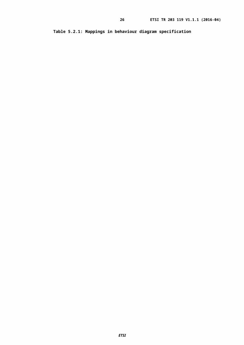
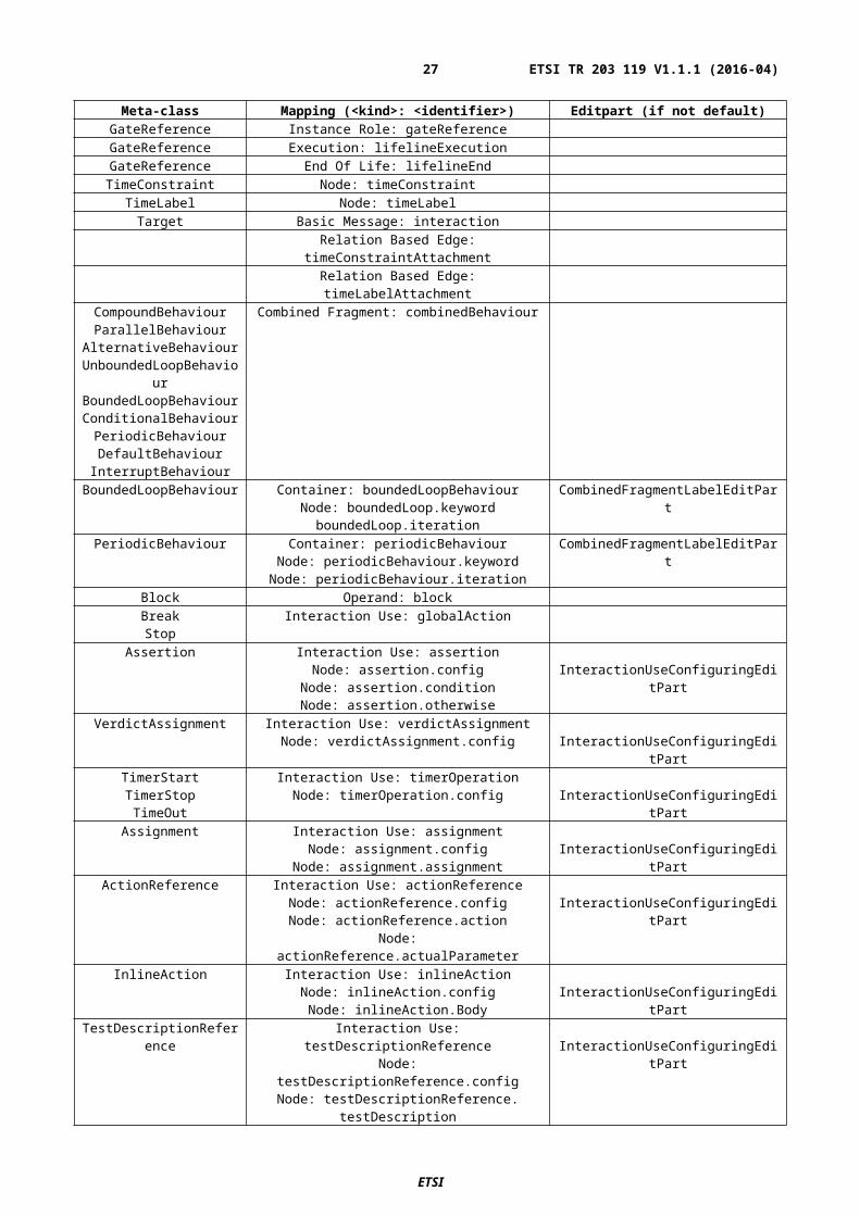
Table 5.2.1: Mappings in behaviour diagram specification
Meta-class Mapping (<kind>: <identifier>) Editpart (if not default)GateReference Instance Role: gateReferenceGateReference Execution: lifelineExecutionGateReference End Of Life: lifelineEndTimeConstraint Node: timeConstraint
TimeLabel Node: timeLabelTarget Basic Message: interaction
Relation Based Edge: timeConstraintAttachmentRelation Based Edge: timeLabelAttachment
CompoundBehaviourParallelBehaviour
AlternativeBehaviourUnboundedLoopBehaviour
BoundedLoopBehaviourConditionalBehaviour
PeriodicBehaviourDefaultBehaviour
InterruptBehaviour
Combined Fragment: combinedBehaviour
BoundedLoopBehaviour Container: boundedLoopBehaviourNode: boundedLoop.keyword
boundedLoop.iteration
CombinedFragmentLabelEditPart
PeriodicBehaviour Container: periodicBehaviourNode: periodicBehaviour.keywordNode: periodicBehaviour.iteration
CombinedFragmentLabelEditPart
Block Operand: blockBreakStop
Interaction Use: globalAction
Assertion Interaction Use: assertionNode: assertion.config
Node: assertion.conditionNode: assertion.otherwise
InteractionUseConfiguringEditPart
VerdictAssignment Interaction Use: verdictAssignmentNode: verdictAssignment.config InteractionUseConfiguringEditPart
TimerStartTimerStopTimeOut
Interaction Use: timerOperationNode: timerOperation.config InteractionUseConfiguringEditPart
Assignment Interaction Use: assignmentNode: assignment.config
Node: assignment.assignmentInteractionUseConfiguringEditPart
ActionReference Interaction Use: actionReferenceNode: actionReference.configNode: actionReference.action
Node: actionReference.actualParameter
InteractionUseConfiguringEditPart
InlineAction Interaction Use: inlineActionNode: inlineAction.configNode: inlineAction.Body
InteractionUseConfiguringEditPart
TestDescriptionReference Interaction Use: testDescriptionReferenceNode: testDescriptionReference.config
Node: testDescriptionReference. testDescriptionNode: testDescriptionReference. actualParameter
Node: testDescriptionReference. componentBindings
InteractionUseConfiguringEditPart
WaitQuiescence
Interaction Use: timeOperationNode: timeOperation.configNode: timeOperation.period
InteractionUseConfiguringEditPart
ComponentInstance Container: componentInstanceNode: componentInstance.name
TopLevelNodeListWithHeaderEditPart
ETSI
ETSI TR 203 119 V1.1.1 (2016-04)21

Table 5.2.2: Mappings in package diagram specification
ETSI
ETSI TR 203 119 V1.1.1 (2016-04)22

Meta-class Mapping (<kind>: <identifier>) Editpart (if not default)Comment Node: comment
Relation Based Edge: commentedElementRelation Based Edge:
simpleDataInstance_dataTypeRelation Based Edge:
structuredDataInstance_dataTypeConnection Element Based Edge:
testConfiguration.connectionDataElementMapping Element Based Edge:
dataElementMapping.mappingRelation Based Edge:
dataElementMapping.associationAnnotationType Container: annotationType
Node: annotationType.nameTopLevelNodeListWithHeaderEditPart
SimpleDataType Container: simpleDataTypeNode: simpleDataType.name
TopLevelNodeListWithHeaderEditPart
Time Container: timeNode: time.name
TopLevelNodeListWithHeaderEditPart
SimpleDataInstance Container: simpleDataInstanceNode: simpleDataInstance.name
TopLevelNodeListWithHeaderEditPart
Package Container: packageContainer: package.name
Node: nameContainer: package.imports
Node: ImportContainer: package.packagedElements
Node: packagedElement
MultipartContainerCompartmentEditPart
NodeListWithHeaderEditPart
Action Container: actionContainer: action.name
Node: nameContainer: action.parameter
Node: ParameterContainer: action.body
Node: Body
MultipartContainerCompartmentEditPart
NodeListWithHeaderEditPart
NodeListWithHeaderEditPart
NodeListWithHeaderEditPartComponentType Container: componentType
Bordered: gateInstanceContainer: componentType.name
Node: nameContainer: componentType.timers
Node: componentType.timerContainer: componentType.variables
Node: componentType.variable
MultipartContainerCompartmentEditPart
NodeListWithHeaderEditPart
TestConfiguration Container: testConfigurationContainer: testConfiguration.name
Node: nameContainer: testConfiguration.configuration
Container: testConfiguration.componentInstanceBordered: testConfiguration.gateReference
Node: testConfiguration.componentInstance.name
MultipartContainerCompartmentEditPart
NodeListWithHeaderEditPart
NodeContainerEditPartTopLevelNodeListWithHeaderEditPart
TestObjective Container: testObjectiveContainer: testObjective.name
Node: nameContainer: testObjective.description
Node: DescriptionContainer: testObjective. objectiveURI
Node: URI
MultipartContainerCompartmentEditPart
NodeListWithHeaderEditPartStructuredDataType Container: structuredDataType
Container: structuredDataType.nameNode: name
Container: structuredDataType.memberNode: member
MultipartContainerCompartmentEditPart
NodeListWithHeaderEditPart
StructuredDataInstance Container: structuredDataInstanceContainer: structuredDataInstance.name
Node: nameContainer:
structuredDataInstance.memberAssignment
MultipartContainerCompartmentEditPart
NodeListWithHeaderEditPart
ETSI
ETSI TR 203 119 V1.1.1 (2016-04)23

Node: memberAssignmentDataResourceMapping Container: dataResourceMapping
Container: dataResourceMapping.nameNode: name
Container: dataResourceMapping.resourceURINode: resourceURI
MultipartContainerCompartmentEditPart
NodeListWithHeaderEditPart
DataElementMapping Container: dataElementMappingContainer: dataElementMapping.name
Node: nameContainer:
dataElementMapping.parameterMappingNode: parameterMapping
MultipartContainerCompartmentEditPart
NodeListWithHeaderEditPart
TestDescription Container: testDescriptionContainer: testDescription.name
Node: nameContainer: testDescription.parameter
Node: ParameterContainer: testDescription.objective
Node: ObjectiveContainer: testDescription.configuration
Node: ConfigurationContainer: testDescription.behaviourContainer: BehaviourConfiguration
Node: Component
MultipartContainerCompartmentEditPart
NodeListWithHeaderEditPart
NodeListWithHeaderEditPart
NodeListWithHeaderEditPart
Function Container: functionContainer: function.name
Node: nameContainer: function.returnType
Node: function.returnType.keywordNode: function.returnType.typeContainer: function.parameter
Node: ParameterContainer: function.body
Node: Body
MultipartContainerCompartmentEditPart
MultiPartLabelEditPart
NodeListWithHeaderEditPart
5.3.3 Exporting Structured Test ObjectivesStructured test objectives are exported as tables in a Word document according to user-defined templates. The templates shall be placed in tables and feature the following placeholders which are mapped to the corresponding elements for a structured test objective referenced as 'self':
<TESTOBJECTIVENAMELABEL_PLACEHOLDER> mapped to 'self.name' <DESCRIPTIONLABEL_PLACEHOLDER> mapped to 'self.description' <URIOFOBJECTIVELABEL_PLACEHOLDER> mapped to 'self.objectiveURI', separated by comma in case
of multiple 'objectiveURI's <CONFIGURATIONLABEL_PLACEHOLDER> mapped to 'self.configuration.name' <PICSSELECTIONLABEL_PLACEHOLDER> mapped to 'self.picsReference' <INITIALCONDITIONSLABEL_PLACEHOLDER> mapped to 'self.initialConditions' <EXPECTEDBEHAVIOURLABEL_PLACEHOLDER> mapped to 'self.expectedBehaviour' <FINALCONDITIONSLABEL_PLACEHOLDER> mapped to 'self.finalConditions' <EXPECTEDBEHAVIOURLABEL_WHENPART_PLACEHOLDER> mapped to
'self.expectedBehaviour.whenClause' <EXPECTEDBEHAVIOURLABEL_THENPART_PLACEHOLDER> mapped to
'self.expectedBehaviour.thenClause'
Each template table shall have a unique identifier in the heading row. The identifier shall be supplied by the user in order to select the corresponding template during export. An example of a template based on the syntax specification in ES 203 119-4 is shown on Table 5.3.1.
Additional placeholders may be defined by users, however, the implementation also needs to add support for them. Since there is currently no framework that provides a high-level means for the specification of such mappings, they shall be implemented at a lower level – in code. Additional filtering may be performed to streamline the output. This may include hiding some keywords and punctuation. The example shown in Table 5.3.1 is exported from the model used in Annex B of ES 203 119-4. A filter has been applied to hide the 'entity' keywords in the output. Finally, 'EventTemplateOccurrence's may be optionally replaced by the corresponding 'EventOccurrenceSpecification' from the the referenced 'EventTemplateSpecification' while applying replacements for overridden 'Argument's and
ETSI
ETSI TR 203 119 V1.1.1 (2016-04)24

'EntityReference's. The details of the export of structured test objectives to Word tables can be found in the 'org.etsi.mts.tdl.to.docx' project in Annex A. The example template as well as additional templates are included in the 'TO_TableTemplates.docx' document.
Table 5.3.1: Structured test objective template example
TO_1_TABLE_TEMPLATE
TP Id <TESTOBJECTIVENAMELABEL_PLACEHOLDER>
Test Objective <DESCRIPTIONLABEL_PLACEHOLDER>
Reference <URIOFOBJECTIVELABEL_PLACEHOLDER>
PICS Selection <PICSSELECTIONLABEL_PLACEHOLDER>
Initial Conditions
<INITIALCONDITIONSLABEL_PLACEHOLDER>
Expected Behaviour
<EXPECTEDBEHAVIOURLABEL_PLACEHOLDER>
Final Conditions
<FINALCONDITIONSLABEL_PLACEHOLDER>
Table 5.3.2: Exported structured test objective according to the template in Table 5.3.1
TP Id TP_7_1_3_1_1
Test Objective
Reference 3GPP TS 36.321 clause 5.3.1
PICS Selection
Initial Conditions
with { the UE in the "E-UTRA RRC_CONNECTED state"}
Expected Behaviour
ensure that { when { the UE receives a "downlink assignment on the PDCCH for the UE’s C-RNTI" and the UE receives a "data in the associated subframe" and the UE performs a HARQ operation } then { the UE sends a "HARQ feedback on the HARQ process" }}
Final Conditions
ETSI
ETSI TR 203 119 V1.1.1 (2016-04)25
5.3.4 Validating ModelsOverview
Means for defining and validating constraints on models are an integral part of modelling environments. Model constraints are used to impose semantic restrictions on top of the abstract syntax provided by the meta-model. There are different approaches for the specification, integration, and validation of such constraints. OCL is the de facto standard for the specification and realisation of constraints on object-oriented meta-models. OCL expressions can be integrated into the meta-model by means of annotations, which can be used for automated validation of model instances, provided adequate tool support is available. An alternative approach is the specification constraints as an add-on which can then be applied to the model instances.
A constraint specification typically consists of a context indicating the meta-class to which the constraint shall apply, and an invariant indicating the conditions that shall hold true in the given context for valid models. For example if a 'NamedElement' shall always have a non-empty name, the constraint specification with OCL is:
context NamedElement inv: not self.name.oclIsUndefined() and self.name.size() > 0
where ‘self‘ refers to the instance of the 'NamedElement' meta-class.
Integrated Approach
The integrated approach involves the definition of semantic constraints within the meta-model itself by means of annotations. Modelling environments can then generate integrated validation facilities based on the annotations. The validation facilities can be invoked automatically so that immediate feedback can be provided to the users when they work with models. The main benefit of an integrated approach is that the constraints become an embedded part of the meta-model. However, there are also certain limitations associated with the integrated approach. Modifications to constraints would require changing the meta-model and related generated resources. Tool support for constraints included as embedded annotations is very inconsistent. Immediate feedback while helpful, can sometimes get in the way and in case a model is refined over multiple steps before it becomes valid, checking constraints at any point before that would be superfluous.
Add-on Approach
In contrast to the integrated approach, the add-on approach relies on semantics constraints defined separately from the meta-model. Such constraints can be checked on demand as required by the specific usage scenario. In addition, the evaluation of such constraints can also be conducted in a more flexible manner, where only subsets of constraints are checked as necessary at a given point in time, thus limiting the amount of superfluous violations for models which are known to be incomplete at that point in time. Add-on constraints can also be modified, maintained, and extended independently from the meta-model. Certain technologies, such as the Epsilon Validation Language (EVL) [i.12] also extend the capabilities of OCL by providing means to specify guards on constraints determining conditions under which the evaluation of a constraint shall be skipped.
The constraints for TDL are realised according to the add-on approach within the 'org.etsi.mts.tdl.constraints' project. The project contains the constraint realisation in the 'tdl.evl' file as well as supporting resources for common and extended functionalities. A standalone launcher is implemented to enable the checking of constraints independent of other tooling. It can also be used as a foundation for integrated solutions.
5.4 Usage Instructions5.4.1 Development EnvironmentTDL graphical viewer is built on top of and developed using Eclipse platform. The Eclipse version in use at the time of writing the present document is "Mars.2".
Steps to set up the development environment:
1) Download and deploy Eclipse Modeling Tools package.
2) Install additional components using Eclipse Modeling Components Discovery:
a. Sirius and
ETSI
ETSI TR 203 119 V1.1.1 (2016-04)26
b. Xtext
3) Import following plugin projects:
a. org.etsi.mts.tdl.graphical.viewpoint
b. org.etsi.mts.tdl.model
c. org.etsi.mts.tdl.graphical.labels.data and
d. org.etsi.mts.tdl.graphical.labels.data.ui
Additional steps for setting up the development environment for the TDL textual editors, constraint implementation, and export of structured test objectives into Word documents include:
4) Install additional components using Eclipse Modeling Components Discovery:
a. Epsilon for validation facilities
5) Import additional plugin projects:
a. org.etsi.mts.tdl.TDLan2 – for editing TDL according to Annex B of ES 203 119-1
b. org.etsi.mts.tdl.TDLan2.ui
c. org.etsi.mts.tdl.TPLan2 – for editing sturctured test objectives according to Annex B of ES 203 119-4
d. org.etsi.mts.tdl.TPLan2.ui
e. org.etsi.mts.tdl.tools.rt – for common tools for translating model instances in different representations
f. org.etsi.mts.tdl.tools.rt.ui
g. org.etsi.mts.tdl.constraints – for OCL constraint implementation
h. org.etsi.mts.tdl.constraints.ui
i. org.etsi.mts.tdl.tools.to.docx – for exporting structured test objectives to Word documents
j. org.etsi.mts.tdl.tools.to.docx.ui
6) Generate resources if necessary:
a. Run the GenerateTDLan2.mwe and/or GenerateTPLan2.mwe workflows in the corresponding projects if necessary
5.4.2 End-user InsturctionsGetting Started
At the time of writing the present document, it is unclear how the implementation is made available for end users. Thus, specific installation instructions are not included here.
Once the viewer is installed, following steps should be taken before new models can be created:
1) Make sure an explorer view is open (Project Explorer or Model Explorer, for example).
2) Create new Modelling Project.
3) In the project, create new TDL Model.
4) On the project, open Viewpoints Selection dialog and enable TDL viewpoint.
The editing of models with tree editors is described in Clause 5.3.1. For creating models with the textual editors, end users shall create a new file with the file extension '.tdlan2' for TDL models according to Annex B of ES 203 119-1 or with the file extension '.tplan2' for TDL models containing structured test objectives specified according to Annex B of ES 203 119-4. The newly created files shall already be associated with the respective editor so that the users can benefit from the enhanced editing capabilities such as syntax checking, syntax highlighting, auto-completion, etc.
ETSI
ETSI TR 203 119 V1.1.1 (2016-04)27

Validating Models
Open the TDL model (with file extensions '.tdl', 'tdlan2' or 'tplan2') with any of the available editors (reflective, faceted, or textual) and press the 'Validate TDL model' button. Any constraint violations will be shown in the console window.
Translating Models
Open the textual representation of a TDL model (with file extensions 'tdlan2' or 'tplan2') and press the 'Translate TDL model' button. The translated representation of the TDL model into an XMI representation according to ES 203 119-3 will be named the same way as the original model (with an additional extension '.tdl') and placed in the same location. An XMI representation of a TDL model may be translated into a textual representation.
Working with Diagrams
In Sirius and, therefore, in the TDL viewer, diagrams are called representations. A representation is always related to one model element that is the root of the representation. There are two representation kinds in the TDL viewer. The 'Generic TDL' representation takes an instance of 'Package' as its root and represents the contents of that 'Package' laid out as a graph. The 'TDL Behavior' representation displays the behaviour of a 'TestDescription' instance laid out as a sequence diagram.
In order to create a new diagram, open the Create Representation wizard on a project, choose the appropriate representation kind and on the last page, select the root element matching the chosen representation kind. Created representation shall be automatically opened in an editor and the representation should also become visible in the explorer view (under the node 'representations.aird').
The diagram editor may be used to adjust the layout of figures, although the viewer implementation takes care of most of the layout tasks.
Exporting Diagrams
Note that although it is not necessary to have the diagrams open while editing models, the diagram editors shall be opened before exporting the diagrams in order to refresh the visual elements with semantic model.
Diagrams may be exported to image files or Microsoft Word documents. Use the context menu of representation nodes in the explorer view.
Exporting Structured Test Objectives
Open the TDL model (with file extensions '.tdl' or 'tplan2') with any of the available editors (reflective, faceted, or textual) and press the 'Generate Word Document Button' button. The generated Word document will be named the same way as the model (with an additional extension '.docx' and placed in the same location.
6 UML Profile Editor6.1 Architecture and Technology FoundationThe UML based editor is also built on top of the Eclipse platform. At a high level, it contains two main components: the UML Profile for TDL (UP4TDL) implementation described in ES 203 119-1, Annex C, and the facilities for editing UP4TDL models. The profile is static. This allows the implementation of derived properties. The profile implementation is independent of the editing facilities provided in the context of this reference implementation and can be used by other UML tools. A model-to-model transformation from UP4TDL models to TDL Ecore models allows generating TDL in the XMI format specified in ES 203 119-3.
The TDL profile implementation is located in the 'org.etsi.mts.up4tdl' project, while the validation implementation is located in the 'org.etsi.mts.up4tdl.validation' project. The implementation of the editing facilities can be found in the 'org.etsi.mts.up4tdl.diagram.*' projects. The 'ElementType' framework is used for manipulating model elements in Papyrus. Specialized 'ElementType's are in located in the 'org.etsi.mts.up4tdl.service.type' project.
ETSI
ETSI TR 203 119 V1.1.1 (2016-04)28

6.2 Implemented Facilities6.2.1 Applying the Profile
Overview
A UML profile allows users to build models with additional constraints and specific properties, while still relying on the UML meta-model. A UP4TDL model is then a UML model with additional constraints and properties tailored towards the domain of TDL.
Stereotype
The extension mechanism of a UML profile is based on stereotypes. A stereotype of a UML profile always extends (directly or indirectly) a UML meta-class. For example the 'ComponentInstance' concept from TDL extends the 'Property' concept of UML and it has the specific property allowing users to define its role ('Tester' or 'SUT').
Applying the UP4TDL profile on a UML model
Applying UP4TDL concepts on a UML model implies the application of UP4TDL stereotypes on UML elements. To do this, the UP4TDL profile (or one of its sub-profiles) shall be added to the package (or the model) containing the UML element as shown in Figure 6.2.1.
Figure 5: UML profile application
The stereotype applied on the UML model allow the specification of stereotype properties. In Figure 6.2.2, the stereotype 'ComponentInstance' is applied to a 'UML::Property'. This allows the user to specify the role property, in this case, 'tester'.
Figure 6: Stereotype property specification
6.2.2 Hints for the Transforming UP4TDL Models into TDL ModelsMost translations are straightforward one-to-one mappings between UP4TDL concepts and concepts from TDL meta-model. The exceptions are detailed below.
ETSI
ETSI TR 203 119 V1.1.1 (2016-04)29

ElementImport
In TDL, 'ElementImport' can reference several 'Element's, while in UML, the corresponding concept 'UML::ElementImport' concept (direct mapping without stereotype) can only reference one. So the model-to-model transformation can potentially turn one 'TDL::ElementImport' into several 'UML::ElementImport's.
SimpleDataInstance and StructuredDataInstance
Both 'SimpleDataInstance' and 'StructuredDataInstance' are mapped to the same concept 'UML::InstanceSpecification'. To determine whether it is a simple or a structured instance, one needs to check the type of the 'UML::InstanceSpecification'. If the 'InstanceSpecification's type is a 'PrimitiveType', then it is a 'SimpleDataInstance', otherwise it is a 'StructuredDataInstance'.
Property Identification
There are two direct mappings from 'UML::Property' to TDL concepts – for 'TDL::Variable' and 'TDL::Member'. In order to determine which kind of property it is, one needs to check the container. If the property is contained in a 'ComponentInstance', then it corresponds to a 'Variable'. Otherwise, if the property is contained in a 'DataType', then it corresponds to a 'Member'.
6.2.3 Editing models with the Model ExplorerAs shown in section 6.2.1, UP4TDL elements can be created from UML elements by applying a stereotype on them. Both steps can be performed in a row from the model explorer, using TDL specific 'New TDL Child' creation options. The model elements are sorted in the 'New TDL Child' menu according to the diagram they are supposed to appear in, as shown in Figure 6.2.3.
Figure 7: Adding TDL-stereotyped elements
6.2.4 Editing models with TDL-specific properties from the 'TDL property view'Editing the properties of a UP4TDL model with the standard property view, can be inconvenient for two reasons. On the one hand, some properties from the UML base meta-class are not relevant for the associated TDL 'Element'. On the other hand, some properties of a TDL 'Element' are not properties of the base meta-class. Even when the properties of a TDL 'Element' and the base UML 'Element' match, they might not have the same name. Editing a UP4TDL model would then require expertise in both UML and TDL, as well as knowledge of the UP4TDL profile specifics. There is a 'TDL Tab' for the property view, which makes the task of editing TDL specific properties easier. Figure 6.2.4 illustrates the property view of a 'ComponentInstance', which contains its 'Name', 'Type', and 'Role' properties.
ETSI
ETSI TR 203 119 V1.1.1 (2016-04)30

Figure 8: Editing TDL-specific properties
6.2.5 Editing models with TDL-specific diagramsEditing a UP4TDL model can be done using the property view and model explorer only. In order to provide a graphical representation of a model being edited, TDL Diagrams specializing UML Diagrams are implemented. There are 3 kinds of TDL Diagrams: TDL DataDefinition Diagram, TDL TestConfiguration Diagram and TDL TestDescription Diagram. There are two main editing facilities for all of these diagrams: the creation of an element using the 'palette' and the 'drag and drop' of an existing element from the model explorer.
The TDL-specific diagrams can be initialized from the model explorer as shown in Figure 6.2.5.
Figure 9: Creating TDL-specific diagrams
The TDL DataDefinition Diagram
The DataDefinition Diagram is based on the UML Class Diagram. It is used to represent the following TDL Elements:
StructuredDataType SimpleDataType MemberAssignment Member DataElementMapping DataResourceMapping ParameterMapping DataInstance GateType
ETSI
ETSI TR 203 119 V1.1.1 (2016-04)31

The palette for the TDL DataDefinition diagram is shown in Figure 6.2.6.
Figure 10: DataDefinition Diagram palette
The TDL TestConfiguration Diagram
The TestConfiguration Diagram is based on the UML Composite Diagram. It is used to represent the following TDL elements:
TestConfiguration ComponentInstance ComponentType GateInstance Connection Variable
The palette for the TDL TestConfiguration Diagram is shown in Figure 6.2.7. An example of the TDL TestConfiguration Diagram is shown in Figure 6.2.8
Figure 11: TestConfiguration Diagram palette
Figure 12: TestConfiguration Diagram example
The following specific behaviours have been implemented for the TestConfiguration Diagram:
Dragging a 'ComponentType to a 'ComponentInstance' specifies the type of the 'ComponentInstance' Dragging a 'GateType' to a 'GateInstance' specifies the type of the 'GateInstance' Dragging a 'GateInstance' from the palette on a 'ComponentInstance' adds it to its 'ComponentType'
ETSI
ETSI TR 203 119 V1.1.1 (2016-04)32

Editing a TDL TestDescription Diagram
The TestDescription Diagram is based on the UML Sequence Diagram. It is used to represent the following TDL elements:
TestDescription Annotation Comment Lifeline CombinedBehaviours:
o Blocko CompoundBehaviouro AlternativeBehaviouro ParalleleBehaviouro UnboundedLoopBehaviouro BoundedLoopBehaviouro ConditionalBehaviouro ExceptionalBehaviouro InteruptBehaviouro PerioudicBehaviour
AtomicBehaviourso ActionReferenceo Assignmento Interactiono TestDescriptionReferenceo VerdictAssignment
The palette for the TDL TestDescription Diagram is shown in Figure 6.2.9.
Figure 13: TestDescription Diagram palette
ETSI
ETSI TR 203 119 V1.1.1 (2016-04)33

Annex A (informative):Technical Realisation of the Reference ImplementationThe technical representation of the TDL reference implementation is available as an electronic attachment which accompanies the present document. The purpose of this annex is to serve as a possible starting point for implementing and extending tools for TDL as described in the present document. See the readme contained in the attachment for details.
ETSI
ETSI TR 203 119 V1.1.1 (2016-04)34

History
Document history
V1.1.1 April 2016 Submitted for approval
ETSI
ETSI TR 203 119 V1.1.1 (2016-04)35


![[PPT]PowerPoint Presentation - IHMC Public Cmaps (2)cursa.ihmc.us/rid=1K22MFNFL-75WFHK-2K50/test-colectivos... · Web viewTEST COLECTIVOS DE INTELIGENCIA TEST DE MATRICES PROGRESIVAS](https://static.fdocuments.net/doc/165x107/5ae485b67f8b9a7b218e84bf/pptpowerpoint-presentation-ihmc-public-cmaps-2cursaihmcusrid1k22mfnfl-75wfhk-2k50test-colectivosweb.jpg)


