SK818_M_WEAM004502_SK818-5
244
-
Upload
ghitacrainic -
Category
Documents
-
view
19 -
download
2
Transcript of SK818_M_WEAM004502_SK818-5

��������������� ������
����������
�������
����������������� ������� ������������������������ ������ �������� ���� ���������� �������� ��� ����� ���� ������ ������ �������� � �������������� ������������ ������ ������ ��� ���� ������� ��� ���� ������������������������������������������������������������� ����������������� �������
����
���� ������ ������ ���������
������� ��� �!��� ��������


FOREWORD
1.1 FOREWORDq This manual is supplied by Komatsu Utility S.p.A. in order to provide customers with all the necessary informa-
tion on the machine and the safety regulations related to it, together with the use and maintenance instructionsthat enable the operator to exploit the capacity of the machine with optimal results and to keep the machine effi-cient over time.
q The operation manual, together with the spare parts catalogue, is an integral part of the machine and must ac-company it, even when it is resold, until its final disposal.
q The manual must be handled with the greatest care and always kept on board the machine, so that it can beconsulted at any moment; it must be placed in the appropriate compartment, where also the ownership docu-ments and the logbook are usually kept.
q This manual must be given to the persons who have to use the machine and carry out the routine maintenanceoperations; they must read the contents carefully more than once, in such a way as to clearly understand whatare the correct operating conditions and the dangerous conditions that must be avoided.In case of loss or damage, request a new copy to Komatsu or to your Komatsu Dealer.
q The illustrations contained in this manual may represent machine configurations that are available on request.Komatsu machines are constantly improved in order to increase their efficiency and reliability; this manual sumsup all the information regarding the most recent techniques applied at the moment in which the machine ismarketed.For any updated information, contact your Komatsu Dealer.
q Punctual periodic annotations regarding the maintenance operations that have been carried out are important tohave a clear prospect of the situation and to know exactly what has been done and what has to be done after thenext maintenance interval. Therefore, it is advisable to consult either the hour meter and the maintenance planfrequently.
q Over the years Komatsu Dealers have gathered considerable experience in customer service.If more information is needed, do not hesitate to contact your Komatsu Utility Dealer: he always knows how toget the best performance from the machine, he can suggest the use of the equipment that is most suitable forspecific needs and can provide the technical assistance necessary for any change that may be required to con-form the machine to the safety standards and traffic rules. Furthermore, Komatsu Dealers also ensure their assistance for the supply of Komatsu genuine spare parts, whi-ch alone guarantee safety and interchangeability.
q The table included in this manual must be filled in with the machine data, which are the data that must always beindicated to the Dealer when requiring assistance and ordering spare parts.
CAUTIONq Improper use and maintenance of this machine may be hazardous and cause serious injuries and even
death.q Operators and maintenance personnel must carefully read this manual before using the machine or per-
forming maintenance operations.q Some actions involved in the operation and maintenance of the machine may cause serious injuries or
even death, if they are not performed in compliance with the instructions given herein.q The procedures and precautions described in this manual are valid for application to the machine only
when it is used correctly.If the machine is used for any purpose or in any way other than those described herein, the operatorshall be responsible for his own safety and for the safety of any other person involved.
1

INFORMATION ON SAFETY
1.2 INFORMATION ON SAFETYMany accidents are caused by insufficient knowledge of and failure to comply with the safety regulations prescri-bed for the maintenance operations that must be performed on the machine.In order to avoid accidents, before starting work and before carrying out any maintenance operation, carefully readand be sure to understand all the information and warnings contained in this manual and given on the plates ap-plied on to the machine.To enable you to use this machine safely, safety precautions and labels are given in this manual and affixed to themachine to give explanations of situations involving potential hazards and of the methods of avoiding such situa-tionsSignal wordsThe following signal words are used to inform you that there is a potential hazardous situation that may lead to per-sonal injury or damage.In this manual and on machine labels, the following signal words are used to express the potential level of hazard.
DANGERq Indicates an imminently hazardous situation which, if not avoided, will result in death or serious injury.
This signal word is to be limited to most extreme situations.
WARNINGq Indicates a potentially hazardous situation which, if not avoided, could result in death or serious injury.
CAUTIONq Indicates a potentially hazardous situation which, if not avoided, may result in minor or moderate injury.
It may also be used to alert against unsafe practices.
Other signal wordsIn addition to the above, the following signal words are used to indicate precautions that should be followed to pro-tect the machine or to give information that is are useful to know.IMPORTANTq This word is used for precautions that must be taken to avoid actions which could shorten the life of the
machine.NOTEq This gives information that is useful to know.
Komatsu cannot reasonably predict every circumstance that might involve a potential hazard during the operationor maintenance of the machine; for this reason, the safety messages included in this manual and applied on to themachine plates may not include all possible safety precautions.If all the procedures and operations prescribed for this machine are kept to, you can be sure that the operator andthe persons in the vicinity of the machine will work in total safety, with no risk of injuries or damage. In case of dou-bt regarding the safety measures necessary for some procedures, contact Komatsu or your local Dealer.
DANGERq Before starting any maintenance operation, position the machine on a firm and level surface, lower the
equipment to the ground, engage the safety locks of the equipment and of the controls and stop the en-gine.
DANGERq To make the information clearer, some illustrations in this manual represent the machine without safety
guards. Do not use the machine without guards and do not start the engine when the engine hood isopen, unless this is expressly prescribed for some specific maintenance operations.
2

INFORMATION ON SAFETY
WARNINGq It is strictly forbidden to modify the setting of the hydraulic system safety valves; Komatsu cannot be
held liable for any damage to persons, property or the machine, if this has been tampered with by modi-fying the standard setting of the hydraulic system.
WARNINGq Before carrying out any electrical welding, disconnect the battery and the alternator (see "2.8.13 PRE-
CAUTIONS CONCERNING THE BATTERY AND THE ALTERNATOR").
WARNINGq Install only authorized additional equipment (see "6.1.4 CHARACTERISTICS OF THE OPTIONAL EQUIP-
MENT OF THE MACHINE VERSION WITH HIGH-FLOW AND SUPER-FLOW HYDRAULIC SYSTEM").
WARNINGq Travel on roads is allowed only if the machine is provided with appropriate lighting, signalling and safety
devices and properly authorized by the relevant papers.Before travelling on roads, make sure that the equipment installed on the machine is homologated andthat the safety locks are correctly engaged.
DANGERq It is absolutely forbidden to operate the machine while standing on the ground.
Every single manoeuvre must be carried out by the operator, correctly seated in driving position.
3

INTRODUCTION
1.3 INTRODUCTION
1.3.1 INTENDED USES The Komatsu MACHINES described in this manual have been designed and constructed to be used by duly trai-ned personnel mainly for EXCAVATION and EARTH-MOVING OPERATIONS.
If provided with suitable safety devices, they can be used with authorized optional equipment having the characte-ristics illustrated at point "6.1 AUTHORIZED OPTIONAL EQUIPMENT".
1.3.2 IMPROPER OR UNAUTHORIZED USES
CAUTIONq This paragraph describes some of the improper or unauthorized uses of the machine; since it is impos-
sible to predict all the possible improper uses, if the machine happens to be used for particular applica-tions, contact your Komatsu Dealer before carrying out the work.
IMPORTANTq The instructions regarding the authorized optional equipment are given in the relevant operation and
maintenance manuals; if the equipment is supplied by Komatsu, these publications are attached to thismanual.
q The instructions regarding the assembly of the authorized equipment, the controls requiring special ar-rangements on the machine and the hydraulic couplings necessary for the operation of the equipmentare grouped in the final section of this manual.
Komatsu MACHINES are constructed exclusively for the handling, excavation and treatment of inert materials;therefore, the following uses are absolutely forbidden:
q USE OF THE MACHINE BY MINORS OR INEXPERIENCED PERSONS.
q USE OF THE MACHINE FOR LIFTING PERSONS OR OBJECTS.
q TRANSPORT OF CONTAINERS WITH FLAMMABLE OR DANGEROUS FLUIDS.
q USE OF THE BUCKET FOR DRIVING OR EXTRACTING PILES.
q USE OF THE MACHINE FOR TOWING DAMAGED VEHICLES.
1.3.3 MAIN CHARACTERISTICS q Simple and easy operation.
q Hydrostatic transmission obtained through a double variable displacement pump and axial piston motors opera-ting epicyclic reduction gears.
q Four driving wheels always engaged through oil-immersed roller chains.
q Main equipment and travel control through servo levers ensuring also combined movements that can be modu-lated proportionally and continually.
q Foot control for the optional equipment (if installed).
q Foot accelerator.
q Lever accelerator.
q Parking brake control.
q Complete series of instruments visible from the operating position.
q Easy maintenance with simplified intervals.
q Road travel (on request).
4

INTRODUCTION
1.3.4 RUNNING-IN Every machine is scrupulously adjusted and tested before delivery.A new machine, however, must be used carefully for the first 100 hours, in order to ensure proper running-in of thevarious components.If the machine is subjected to excessive work load at the beginning of operation, its potential yield and its functio-nality will be untimely reduced. Every new machine must be used carefully, paying special attention to the following indications:
q After starting the engine, let it idle for 5 minutes, in such a way as to warm it up gradually before actual operation.
q Avoid operating the machine with the limit loads allowed or at high speed.
q Avoid abrupt starts or accelerations, useless sudden decelerations and abrupt reversals.
q After the first 50 hours of use, carry out the following operations, in addition to those to be performed every 50hours:1 - Check the gearing chain tension.2 - Check the wheel nut tightening.
q After the first 250 hours of use, carry out the following operations, in addition to those to be performed every 250hours:1 - Change the hydraulic circuit drain filter.
SYNTHETIC BIODEGRADABLE OIL TYPE HEESOn machines in which the synthetic biodegradable oil type HEES is used, carry out the following operations in ad-dition to the routine maintenance:
q After the first 50 hours of operation, change the hydraulic circuit drain filter.
q After the first 500 hours of operation, change the hydraulic circuit oil.
IMPORTANTq When changing the oil filters (cartridges), check their inner part to make sure that there are no deposits.
If considerable deposits can be observed, find out what may have caused them before restarting the ma-chine.
q The number of operating hours is indicated by the hour meter.
5

PRODUCT IDENTIFICATION
1.4 PRODUCT IDENTIFICATIONThe Komatsu COMPACT LOADER and its main components are identified by serial numbers stamped on theidentification plates.The serial number and the identification numbers of the components are the only numbers that must always be in-dicated to the Dealer when requiring assistance and ordering spare parts.
1.4.1 MACHINE SERIAL NUMBERThe machine serial number is stamped on the inner wall of therear right pillar.
1.4.2 MACHINE IDENTIFICATION PLATE AND PRODUCT IDENTIFICATION NUMBER (PIN)
The Komatsu MACHINES described in this manual are provi-ded with the CE mark, which certifies that they are in com-pliance with the CE harmonized standards.The plate with the mark is applied on to the inner wall of the re-ar right pillar.
���������
���������
37A-98-11820
MODELLO - MODELTYP - MODELE
kg
kw
MANUFACTURED BY KOMATSU UTILITY EUROPE S.p.A.36025 NOVENTA VICENTINA (VI) - ITALY
MATRICOLA N˚ - SERIAL N˚FABR. NR. - SERIE NR.ANNO - YEARBAUJAHR - ANNEEMASSA TOTALE - TOTAL WEIGHTGESAMTGEWICHT - POIDS TOTALPOTENZA MOTORE - ENGINE POWERLEISTUNG - PUISSANCE MOTEUR
Product Identification Number
PIN
RWA39300
MODEL
kg
kw
MANUFACTURED BY KOMATSU UTILITY EUROPE S.p.A.36025 NOVENTA VICENTINA (VI) - ITALY
SERIAL N˚
YEAR
TOTAL WEIGHT
ENGINE POWER
Product Identification Number
PIN
6

PRODUCT IDENTIFICATION
1.4.3 ENGINE SERIAL NUMBER AND EXHAUST GAS EMISSION PLATE
The plate (1) indicating the engine serial number and theexhaust gas emission plate are positioned on the upper side ofthe tappet cover.
1.4.4 TRAVEL REDUCTION GEAR SERIAL NUMBER
The serial number of the travel reduction gear is stamped onthe plate positioned on the hydraulic motor cover.
1.4.5 CAB SERIAL NUMBER The cab serial number is stamped on the plate positioned onthe right side of the base cross member.
1.4.6 EXCAVATOR IDENTIFICATION PLATE (if installed)
The excavator identification number is stamped on the platepositioned on the left side of the control panel.
��������
�
�
�������
�������
��������
7

PRODUCT IDENTIFICATION
1.4.7 SERIAL NUMBERS AND DEALER’S ADDRESSMachine N° Model
Engine N°
Dealer:
Address:
Tel.
Person to contact:
NOTES:
Excavator (if installed) N°
Travel reduction gear N°
Cab N°
Product identification number (PIN)
8

TABLE OF CONTENTS
TABLE OF CONTENTSFOREWORD1.1 FOREWORD.......................................................................................................................................... 11.2 INFORMATION ON SAFETY................................................................................................................ 21.3 INTRODUCTION ................................................................................................................................... 4
1.3.1 INTENDED USES .................................................................................................................... 41.3.2 IMPROPER OR UNAUTHORIZED USES................................................................................ 41.3.3 MAIN CHARACTERISTICS...................................................................................................... 41.3.4 RUNNING-IN ............................................................................................................................ 5
1.4 PRODUCT IDENTIFICATION ............................................................................................................... 61.4.1 MACHINE SERIAL NUMBER................................................................................................... 61.4.2 MACHINE IDENTIFICATION PLATE AND PRODUCT IDENTIFICATION NUMBER (PIN) ... 61.4.3 ENGINE SERIAL NUMBER AND EXHAUST GAS EMISSION PLATE ................................... 71.4.4 TRAVEL REDUCTION GEAR SERIAL NUMBER ................................................................... 71.4.5 CAB SERIAL NUMBER ........................................................................................................... 71.4.6 EXCAVATOR IDENTIFICATION PLATE (if installed) .............................................................. 71.4.7 SERIAL NUMBERS AND DEALER’S ADDRESS .................................................................... 8
SAFETY AND ACCIDENT PREVENTION2.1 SAFETY, NOISE AND VIBRATION PLATES....................................................................................... 16
2.1.1 POSITION OF THE SAFETY PLATES .................................................................................... 162.1.1.1 SAFETY PLATES ................................................................................................... 162.1.1.2 SAFETY PLATES FOR MACHINES WITH EXCAVATOR ..................................... 18
2.1.2 PICTOGRAMS AND RELEVANT MEANINGS......................................................................... 202.1.3 POSITION OF THE NOISE PLATES ...................................................................................... 232.1.4 VIBRATIONS TO WHICH THE OPERATOR IS SUBJECTED ................................................ 23
2.2 GENERAL PRECAUTIONS .................................................................................................................. 242.2.1 GENERAL SAFETY RULES .................................................................................................... 242.2.2 SAFETY DEVICES AND GUARDS.......................................................................................... 242.2.3 CLOTHING AND PERSONAL PROTECTION ITEMS ............................................................ 242.2.4 UNAUTHORIZED MODIFICATIONS ....................................................................................... 252.2.5 LEAVING THE OPERATORS SEAT ....................................................................................... 252.2.6 GETTING ON AND OFF THE MACHINE ................................................................................ 262.2.7 CHECKING THE REAR-VIEW MIRRORS (if installed) ........................................................... 262.2.8 PREVENTING FIRES DUE TO FUEL AND OIL ..................................................................... 272.2.9 PREVENTING BURNS ............................................................................................................ 272.2.10 PREVENTING DAMAGE DUE TO ASBESTOS POWDER .................................................... 282.2.11 PREVENTING DAMAGE CAUSED BY THE WORK EQUIPMENT ........................................ 282.2.12 FIRE EXTINGUISHERS AND FIRST AID KIT ........................................................................ 292.2.13 PRECAUTIONS CONCERNING THE CAB STRUCTURE ...................................................... 292.2.14 PRECAUTIONS CONCERNING THE EQUIPMENT ............................................................... 29
2.3 PRECAUTIONS TO BE TAKEN BEFORE STARTING THE ENGINE................................................. 302.3.1 SAFETY ON THE WORK SITE ............................................................................................... 302.3.2 FIRE PREVENTION ................................................................................................................ 302.3.3 PRECAUTIONS TO BE TAKEN FOR THE OPERATOR'S CAB ............................................. 302.3.4 ROOM VENTILATION ............................................................................................................. 312.3.5 PRECAUTIONS TO BE TAKEN FOR THE LIGHTS (if installed)............................................. 312.3.6 CLEANING THE WINDOWS AND THE REAR-VIEW MIRRORS - CHECKING
THE WINDSHIELD WIPER BLADES (if installed) ................................................................... 31
9

TABLE OF CONTENTS
2.4 PRECAUTIONS TO BE TAKEN WHEN WORKING............................................................................. 322.4.1 STARTING THE ENGINE......................................................................................................... 322.4.2 RULES TO BE FOLLOWED WHEN TRAVELLING ON ROADS ............................................. 322.4.3 CHECKS FOR TRAVELLING IN REVERSE ........................................................................... 332.4.4 MOVING THE MACHINE ........................................................................................................ 342.4.5 WORKING ON SLOPES ......................................................................................................... 342.4.6 PREVENTING ELECTROCUTION........................................................................................... 362.4.7 VISIBILITY ................................................................................................................................ 372.4.8 WORKING ON ICY OR SNOW-COVERED SURFACES......................................................... 372.4.9 PREVENTING DAMAGE CAUSED BY THE WORK EQUIPMENT ......................................... 372.4.10 WORKING ON LOOSE GROUND ........................................................................................... 372.4.11 PARKING THE MACHINE ....................................................................................................... 38
2.5 TRANSPORTING THE MACHINE ON OTHER VEHICLES ................................................................. 392.5.1 LOADING AND UNLOADING THE MACHINE ........................................................................ 392.5.2 THE ROUTE ............................................................................................................................. 39
2.6 BATTERY .............................................................................................................................................. 402.6.1 SAFETY PRECAUTIONS FOR WORK ON BATTERIES ........................................................ 402.6.2 STARTING WITH BOOSTER CABLES ................................................................................... 40
2.7 PRECAUTIONS FOR EMERGENCY RECOVERY............................................................................... 412.8 PRECAUTIONS TO BE TAKEN DURING MAINTENANCE................................................................. 43
2.8.1 WARNING PLATES ................................................................................................................. 432.8.2 TOOLS ..................................................................................................................................... 432.8.3 PERSONNEL............................................................................................................................ 442.8.4 EQUIPMENT ........................................................................................................................... 442.8.5 WORKING UNDER THE MACHINE ........................................................................................ 442.8.6 KEEPING THE MACHINE CLEAN .......................................................................................... 442.8.7 USE OF THE ENGINE DURING MAINTENANCE ................................................................... 452.8.8 PERIODICAL CHANGE OF THE PARTS THAT ARE CRITICAL FOR SAFETY..................... 452.8.9 STOP THE ENGINE BEFORE CARRYING OUT ANY MAINTENANCE OPERATION
OR INSPECTION .................................................................................................................... 452.8.10 RULES FOR REFUELLING AND ADDING OIL ...................................................................... 462.8.11 CHECKING THE COOLANT LEVEL IN THE RADIATOR ....................................................... 462.8.12 USING LAMPS ........................................................................................................................ 462.8.13 PRECAUTIONS CONCERNING THE BATTERY AND THE ALTERNATOR ......................... 472.8.14 PRECAUTIONS CONCERNING THE STARTER ................................................................... 472.8.15 PRECAUTIONS CONCERNING HIGH-PRESSURE HOSES.................................................. 482.8.16 PRECAUTIONS TO BE TAKEN WHEN WORKING ON HIGH-PRESSURE SYSTEMS ........ 482.8.17 PRECAUTIONS FOR MAINTENANCE WORK INVOLVING HIGH TEMPERATURES
AND PRESSURES .................................................................................................................. 482.8.18 COOLING FAN AND FAN BELT ............................................................................................. 492.8.19 WASTE MATERIALS ............................................................................................................... 492.8.20 PRECAUTIONS TO BE TAKEN WHEN INFLATING THE TYRES .......................................... 492.8.21 PRECAUTIONS TO BE TAKEN WHEN USING THE SYNTHETIC BIODEGRADABLE
OIL TYPE «HEES»................................................................................................................... 50
10

TABLE OF CONTENTS
DESCRIPTION AND USE OF THE MACHINE3.1 SAFETY LOCKS ................................................................................................................................... 52
3.1.1 LOADER LOCKS ..................................................................................................................... 523.1.2 EXCAVATOR LOCKS (if installed)........................................................................................... 543.1.3 ASPHALT CUTTER LOCKS (if installed) ................................................................................. 56
3.2 GENERAL VIEWS................................................................................................................................. 573.2.1 FRONT GENERAL VIEW......................................................................................................... 573.2.2 REAR GENERAL VIEW ........................................................................................................... 583.2.3 CAB INSIDE GENERAL VIEW ................................................................................................ 59
3.3 INSTRUMENTS AND CONTROLS....................................................................................................... 613.3.1 INSTRUMENTS........................................................................................................................ 613.3.2 WARNING LIGHTS .................................................................................................................. 633.3.3 SWITCHES UND PUSH BUTTONS......................................................................................... 683.3.4 ELECTRICAL ACCESSORIES ............................................................................................... 733.3.5 MACHINE CONTROLS ............................................................................................................ 75
3.4 FUSES AND RELAYS........................................................................................................................... 953.4.1 MACHINE FUNCTION FUSES ............................................................................................... 953.4.2 MAIN FUSE ............................................................................................................................. 963.4.3 RELAYS .................................................................................................................................. 97
3.5 GUARDS AND DRIVER’S SEAT.......................................................................................................... 993.5.1 ENGINE HOOD ........................................................................................................................ 993.5.2 REAR PANEL .......................................................................................................................... 1003.5.3 CAB .......................................................................................................................................... 101
3.5.3.1 RAISING THE CAB ................................................................................................ 1023.5.4 STANDARD SEAT .................................................................................................................. 1043.5.5 CUSHIONED SEAT ................................................................................................................. 1043.5.6 SAFETY BELT.......................................................................................................................... 1053.5.7 EMERGENCY EXIT ................................................................................................................. 1053.5.8 TECHNICAL DOCUMENTATION CASE.................................................................................. 1063.5.9 FIRE EXTINGUISHER ............................................................................................................ 1063.5.10 FIRST AID KIT ......................................................................................................................... 106
3.6 USE OF THE MACHINE........................................................................................................................ 1073.6.1 CHECKS BEFORE STARTING THE ENGINE......................................................................... 107
3.6.1.1 VISUAL CHECKS ................................................................................................... 1073.6.1.2 DAILY CHECKS...................................................................................................... 1073.6.1.3 OPERATIONAL CHECKS ...................................................................................... 108
3.6.2 STARTING THE ENGINE ........................................................................................................ 1093.6.2.1 STARTING WITH WARM ENGINE OR IN TEMPERATE CLIMATES ................... 1093.6.2.2 STARTING WITH COLD ENGINE OR IN COLD CLIMATES ................................ 110
3.6.3 WARMING THE ENGINE......................................................................................................... 1113.6.4 HEATING THE HYDRAULIC OIL............................................................................................. 1113.6.5 HOW TO MOVE THE MACHINE (ISO PATTERN CONTROL SYSTEMERN) ........................ 111
3.6.5.1 STEERING (CHANGING DIRECTION) .................................................................. 1133.6.6 HOW TO MOVE THE MACHINE (OPTIONAL PATTERN CONTROL SYSTEM).................... 115
3.6.6.1 STEERING (CHANGING DIRECTION) .................................................................. 1173.6.7 MOVING ON SLOPES ............................................................................................................. 1193.6.8 MAXIMUM IMMERSION DEPTH ............................................................................................. 120
3.7 PARKING THE MACHINE .................................................................................................................... 1213.7.1 PARKING ON LEVEL GROUND ............................................................................................. 1213.7.2 PARKING ON SLOPES............................................................................................................ 122
3.8 STOPPING THE ENGINE ..................................................................................................................... 123
11

TABLE OF CONTENTS
3.9 TRANSPORTING THE MACHINE ON OTHER VEHICLES ................................................................. 1243.9.1 LOADING AND UNLOADING THE MACHINE......................................................................... 1243.9.2 TRANSPORT............................................................................................................................ 125
3.10 HOW TO LIFT THE MACHINE.............................................................................................................. 1263.11 PRECAUTIONS TO BE TAKEN IN THE COLD SEASON ................................................................... 127
3.11.1 FUEL AND LUBRICANTS ........................................................................................................ 1273.11.2 COOLANT ................................................................................................................................ 1273.11.3 BATTERY ................................................................................................................................. 1283.11.4 OTHER PRECAUTIONS .......................................................................................................... 1283.11.5 PRECAUTIONS TO BE TAKEN AT THE END OF WORK ...................................................... 128
3.12 PRECAUTIONS TO BE TAKEN IN THE WARM SEASON.................................................................. 1293.13 USING THE WORK EQUIPMENT......................................................................................................... 130
3.13.1 LOWERING THE EQUIPMENT IN CASE OF MACHINE FAILURE ........................................ 1303.13.2 ORGANIZING THE WORK ARE .............................................................................................. 1313.13.3 LOADING MATERIAL ON HEAPS AND ON LEVEL SURFACES .......................................... 1323.13.4 LOADING MATERIAL ON SLOPES ........................................................................................ 1333.13.5 DIGGING METHOD.................................................................................................................. 1343.13.6 CHANGING THE BUCKET OR THE EQUIPMENT WITH STANDARD RAPID COUPLING... 135
3.13.6.1 RELEASING THE BUCKET .................................................................................... 1363.13.6.2 COUPLING THE BUCKET...................................................................................... 136
3.13.7 CHANGING THE BUCKET OR THE EQUIPMENT WITH OPTIONAL RAPID COUPLING .... 1383.13.7.1 REMOVING THE BUCKET OR THE EQUIPMENT ................................................ 1393.13.7.2 CONNECTING THE BUCKET ................................................................................ 1403.13.7.3 CHECKING THE POSITION OF THE LOCKING PINS .......................................... 1413.13.7.4 ADJUSTING THE LOCKING PINS ......................................................................... 142
3.14 LONG PERIODS OF INACTIVITY ........................................................................................................ 1433.14.1 BEFORE THE PERIOD OF INACTIVITY ................................................................................ 1433.14.2 DURING THE PERIOD OF INACTIVITY.................................................................................. 1443.14.3 AFTER THE PERIOD OF INACTIVITY .................................................................................... 144
3.15 TROUBLESHOOTING .......................................................................................................................... 1453.15.1 HOW TO REMOVE THE MACHINE......................................................................................... 1453.15.2 IF THE FUEL HAS BEEN COMPLETELY DEPLETED............................................................ 1453.15.3 IF THE BATTERY IS DEPLETED ............................................................................................ 146
3.15.3.1 STARTING WITH BOOSTER CABLES .................................................................. 1473.15.4 OTHER TROUBLES................................................................................................................. 148
3.15.4.1 ELECTRICAL CIRCUIT........................................................................................... 1483.15.4.2 HYDRAULIC SYSTEM............................................................................................ 1483.15.4.3 ENGINE................................................................................................................... 1493.15.4.4 HYDROSTATIC TRANSMISSION ......................................................................... 150
12

TABLE OF CONTENTS
MAINTENANCE4.1 GUIDE TO MAINTENANCE.................................................................................................................. 1544.2 MAINTENANCE NOTES....................................................................................................................... 156
4.2.1 NOTES REGARDING THE ENGINE ....................................................................................... 1564.2.1.1 ENGINE OIL............................................................................................................ 1564.2.1.2 COOLANT............................................................................................................... 1564.2.1.3 FUEL ....................................................................................................................... 157
4.2.2 NOTES REGARDING THE HYDRAULIC SYSTEM................................................................. 1574.2.3 NOTES REGARDING THE ELECTRICAL SYSTEM ............................................................... 1574.2.4 NOTES REGARDING LUBRICATION ..................................................................................... 1584.2.5 PARTS SUBJECT TO WEAR THAT PERIODICALLY NEED CHANGING.............................. 158
4.3 FUEL, COOLANT AND LUBRICANTS................................................................................................. 1594.3.1 HOMOLOGATED SYNTHETIC BIODEGRADABLE LUBRICANTS TYPE HEES ................... 161
4.4 DRIVING TORQUES FOR SCREWS AND NUTS ................................................................................ 1624.4.1 STANDARD DRIVING TORQUES ........................................................................................... 1624.4.2 SPECIFIC DRIVING TORQUES .............................................................................................. 162
4.5 LUBRICATION ...................................................................................................................................... 1634.5.1 LUBRICATION DIAGRAM........................................................................................................ 163
4.6 PERIODICAL CHANGE OF THE COMPONENTS CONNECTED WITH SAFETY .............................. 1644.6.1 CRITICAL PARTS FOR SAFETY............................................................................................. 165
4.7 MAINTENANCE PLAN.......................................................................................................................... 1714.8 MAINTENANCE PROCEDURE ............................................................................................................ 173
4.8.1 WHEN REQUIRED................................................................................................................... 1734.8.1.a CHECKING, CLEANING OR CHANGING THE AIR CLEANER CARTRIDGE....... 1734.8.1.b TYRE ROTATION .................................................................................................. 1744.8.1.c DRAINING THE FUEL TANK ................................................................................. 1754.8.1.d RELEASING THE PARKING BRAKE .................................................................... 1764.8.1.e CHECKING THE BATTERY CHARGE LEVEL....................................................... 177
4.8.2 CHECKS BEFORE STARTING................................................................................................ 1784.8.2.a VARIOUS CHECKS ................................................................................................ 1784.8.2.b CHECKING THE COOLANT LEVEL ...................................................................... 1784.8.2.c CHECKING THE FUEL LEVEL............................................................................... 1794.8.2.d CHECKING THE ENGINE OIL LEVEL ................................................................... 1804.8.2.e CHECKING THE OIL LEVEL IN THE HYDRAULIC CIRCUIT ............................... 1814.8.2.f CHECKING THE WATER SEPARATOR FOR SEDIMENTS AND WATER .......... 1824.8.2.g CHECKING THE WIRING SYSTEM....................................................................... 182
4.8.3 MAINTENANCE AFTER THE FIRST 50 HOURS OF OPERATION........................................ 1834.8.4 MAINTENANCE EVERY 50 HOURS OF OPERATION ........................................................... 183
4.8.4.a CHECKING THE TYRE PRESSURE ..................................................................... 1834.8.4.b CHECKING THE COOLANT LEVEL IN THE RADIATOR ...................................... 183
4.8.5 MAINTENANCE AFTER THE FIRST 250 HOURS OF OPERATION...................................... 1844.8.6 MAINTENANCE EVERY 250 HOURS OF OPERATION ......................................................... 184
4.8.6.a ADJUSTING THE FAN BELT TENSION................................................................. 1844.8.6.b CHECKING THE GEARING CHAIN TENSION ...................................................... 1854.8.6.c CLEANING THE OUTSIDE OF THE RADIATORS................................................. 1874.8.6.d CHECKING THE WHEEL NUT DRIVING TORQUE............................................... 1874.8.6.e CHECKING THE OIL LEVEL IN THE FINAL TRANSMISSIONS .......................... 1884.8.6.f LUBRICATING THE JOINTS .................................................................................. 1894.8.6.g CHANGING THE ENGINE OIL ............................................................................... 1904.8.6.h CHANGING THE ENGINE OIL FILTER.................................................................. 191
4.8.7 MAINTENANCE AFTER THE FIRST 500 HOURS OF OPERATION (Only for machines filled with synthetic biodegradable oil type HEES) .................................... 192
13

TABLE OF CONTENTS
4.8.8 MAINTENANCE EVERY 500 HOURS OF OPERATION ......................................................... 1924.8.8.a CHANGING THE FUEL FILTER ............................................................................. 1924.8.8.b CHANGING THE HYDRAULIC OIL DRAIN FILTER .............................................. 1944.8.8.c CLEANING THE WATER SEPARATOR................................................................. 1954.8.8.d DRAINING THE HYDRAULIC OIL TANK
(Only for machines filled with synthetic biodegradable oil type HEES) ................... 1964.8.9 MAINTENANCE EVERY 1000 HOURS OF OPERATION ....................................................... 197
4.8.9.a CHANGING THE OIL IN THE FINAL TRANSMISSION ......................................... 1974.8.9.b CHANGING THE HYDRAULIC SYSTEM OIL AND CLEANING THE SUCTION
FILTER .................................................................................................................... 1984.8.9.c CHECKING AND ADJUSTING THE ENGINE VALVE CLEARANCE..................... 199
4.8.10 MANUTENZIONE OGNI 2000 ORE ......................................................................................... 2004.8.10.a CHANGING THE COOLANT .................................................................................. 2004.8.10.b CHANGING THE SUCTION FILTER ...................................................................... 2014.8.10.c CHECKING THE ALTERNATOR AND THE STARTER ......................................... 202
TECHNICAL SPECIFICATIONS5.1 TECHNICAL DATA ............................................................................................................................... 204
5.1.1 STANDARD MACHINE OVERALL DIMENSIONS ................................................................... 2045.1.2 MACHINE OVERALL DIMENSIONS WITH OPTIONAL EQUIPMENT .................................... 2065.1.3 TECHNICAL CHARACTERISTICS .......................................................................................... 210
AUTHORIZED OPTIONAL EQUIPMENT6.1 AUTHORIZED OPTIONAL EQUIPMENT ............................................................................................. 214
6.1.1 PRECAUTIONS REGARDING SAFETY .................................................................................. 2146.1.2 PRECAUTIONS REGARDING THE INSTALLATION OF EQUIPMENT.................................. 2156.1.3 CHARACTERISTICS OF THE STANDARD MACHINE OPTIONAL EQUIPMENT.................. 2166.1.4 CHARACTERISTICS OF THE OPTIONAL EQUIPMENT OF THE MACHINE VERSION
WITH HIGH-FLOW AND SUPER-FLOW HYDRAULIC SYSTEM............................................ 217
6.2 CHANGING THE AUTHORIZED EQUIPMENT .................................................................................... 2186.2.1 CONNECTING THE EXCAVATOR .......................................................................................... 2186.2.2 CONNECTING THE HYDRAULIC CIRCUIT ............................................................................ 2196.2.3 CONNECTING THE RETURN CIRCUIT WITH DIRECT DRAINAGE INTO THE TANK ........ 2216.2.4 PREPARING THE MACHINE FOR THE USE OF THE EXCAVATOR .................................... 2226.2.5 USING THE MACHINE WITH THE EXCAVATOR ................................................................... 222
6.3 PALLET FORKS ................................................................................................................................... 2236.4 CHANGING THE OPERATING PATTERN........................................................................................... 224
6.4.1 HOW TO CHANGE THE OPERATING PATTERN .................................................................. 226
6.5 HAND & FOOT CONTROL SYSTEM ................................................................................................... 2276.5.1 MACHINE CONTROLS ............................................................................................................ 227
6.5.1.1 TRAVEL AND STEERING CONTROL LEVERS..................................................... 2286.5.1.2 WORK EQUIPMENT CONTROL PEDALS (LOADER ARM AND BUCKET).......... 2306.5.1.3 AUXILIARY HYDRAULIC KIT CONTROL............................................................... 233
6.5.2 HOW TO MOVE THE MACHINE (HAND & FOOT CONTROL SYSTEM) ............................... 2366.5.2.1 STEERING (CHANGING DIRECTION) .................................................................. 238
14

���������������� ��������
15

SAFETY, NOISE AND VIBRATION PLATES
2.1 SAFETY, NOISE AND VIBRATION PLATES
2.1.1 POSITION OF THE SAFETY PLATESq The safety plates must always be legible and in good conditions; for this reason, if they are dirty with dust, oil or
grease, it is necessary to clean them with a solution made of water and detergent. Do not use fuel, petrol or solvents.
q If the plates are damaged, ask for new ones to Komatsu or to your Komatsu Dealer.
q In case of replacement of a component provided with a safety plate, make sure that this plate is applied also onthe new part.
q The machine can be provided with other plates in addition to those indicated below; in any case, keep also to theinstructions given in the additional plates.
2.1.1.1 SAFETY PLATESRWA37010
RWA00030
16

SAFETY, NOISE AND VIBRATION PLATES
RWA00010
RWA37020
17

SAFETY, NOISE AND VIBRATION PLATES
2.1.1.2 SAFETY PLATES FOR MACHINES WITH EXCAVATOR
RWA37030
RWA00030
RWA00020
18

SAFETY, NOISE AND VIBRATION PLATES
RWA37040
RWA00010RWA00020
19

SAFETY, NOISE AND VIBRATION PLATES
2.1.2 PICTOGRAMS AND RELEVANT MEANINGS The warning and danger plates applied on to the machine are accompanied or represented by pictograms.The personnel in charge with the operation and maintenance of the machine must know the symbols contained inthe pictograms perfectly; the following description illustrates what they look like and their respective meanings.
DANGER IN THE WORK AREA(Only for machines with excavator) q Do not approach or stand within the equipment operating ra-
dius when the boom and the bucket of the excavator are rai-sed.
DO NOT OPEN THE HOOD q Do not open or remove the hood while the engine is running.
CONSULT THE MANUAL q Carefully read the contents of the manual before using the
machine or performing maintenance operations.
HYDRAULIC OIL TOPPING UP
RWA00020
RWA00010
RWA00030
RWA00050
20

SAFETY, NOISE AND VIBRATION PLATES
BIOLOGICAL HYDRAULIC OIL TOPPING UP
REFUELLING
ENGINE LUBRICATING OIL FILTER
FUEL FILTER
ENGINE AIR SUCTION FILTER
ENGINE COOLANT
RWA34380BIO-OIL
DRWA00040
RWA00080
DRWA00060
RWA00090
RWA00130
21

SAFETY, NOISE AND VIBRATION PLATES
ENGINE COOLANT PRESSURE
HYDRAULIC OIL LEVEL
HYDRAULIC OIL FILTER
ELECTRIC OUTLET
ANCHORAGE POINT
EMERGENCY EXIT
LIFTING POINT
RWA00110
RWA00100
RWA00070
12 VRWA00120
RWA00200
RWA00190
RWA04920
22

SAFETY, NOISE AND VIBRATION PLATES
2.1.3 POSITION OF THE NOISE PLATES q The noise plates must always be legible and in good condi-
tions; for this reason, if they are dirty with dust, oil or grease,it is necessary to clean them with a solution made of waterand detergent. Do not use fuel, petrol or solvents.
q If the plates are damaged, ask for new ones to Komatsu orto your Komatsu Dealer.
q In case of replacement of a component provided with a noi-se plate, make sure that this plate is applied also on the newpart.
NOISE OUTSIDE THE CAB q This value indicates the noise level outside the machine and
refers to the noise perceived by the persons who are in thevicinity of the work area.
NOISE INSIDE THE CAB q This value indicates the maximum noise level perceived by
the operatorís ears inside the cab.
2.1.4 VIBRATIONS TO WHICH THE OPERATOR IS SUBJECTED q According to the results of the tests carried out to determine the vibrations transmitted to the operator by the ma-
chine, the upper limbs are subjected to vibrations lower than 2.5 m/sq.sec., while the seated part of the body issubjected to vibrations lower than 0.5 m/sq sec.
RWA37050
2000/14/ECRWA37060
10 dB1
RWA36350ISO 6396
8 dB6
23

GENERAL PRECAUTIONS
2.2 GENERAL PRECAUTIONS
2.2.1 GENERAL SAFETY RULES q Only trained and authorized personnel can use the machine and perform maintenance operations.
q When using the machine or performing maintenance operations, follow all the safety rules, precautions and in-structions.
q When working with other operators or when the work site is often occupied by other operators, make sure thateveryone knows and understands all the agreed signals and, in any case, that everyone works in such a way asto be able to see the machine and to be visible to the operator.
2.2.2 SAFETY DEVICES AND GUARDS q Make sure that all the guards and covers are in the correct position. Have guards and covers changed or repai-
red if damaged. Neither use the machine without guards, nor remove the guards when the engine is running.
q Always use the proper safety devices to lock the machine when parking and remember to fasten the safety belt.
q For the safety devices, see "3.1 SAFETY LOCKS".
q For the safety belt, see "3.5.6 SAFETY BELT".
q Do not remove the safety devices and always keep them in good operating conditions.
q Improper use of the safety devices may lead to serious injuries or even death.
2.2.3 CLOTHING AND PERSONAL PRO-TECTION ITEMS
q Do not wear large or loose clothes, rings and watches and donot approach the machine with loose long hair, since theycan get entagled in the moving parts of the machine and cau-se serious injuries and damage.Avoid also wearing clothes dirty with oil or fuel, since they areflammable.
q Wear a hard hat, goggles, safety shoes, mask, gloves andheadphones when operating the machine or performingmaintenance operations.
q Always wear safety goggles, a hard hat and heavy gloves ifyour job involves scattering metal chips or minute materials;these precautions are particularly useful when driving theequipment connection pins with a hammer and when blowingcompressed air into the air filter and the radiator to cleanthem. During these operations, make also sure that no one is stan-ding or working near the machine without the necessary pro-tections.
q When working for 8 hours with a noise level exceeding 90dBA, it is necessary to use headphones or ear plugs and tobe particularly careful, especially at the end of the work shift.
RWA00960
24

GENERAL PRECAUTIONS
2.2.4 UNAUTHORIZED MODIFICATIONS q Any modification made without the authorization of Komatsu can involve hazards.
q Before making a modification, consult your Komatsu Dealer. Komatsu declines any responsibility for injuries ordamage caused by unauthorized modifications.
2.2.5 LEAVING THE OPERATORS SEAT q When leaving the operatorís seat, even if temporarily, make
sure that the machine is in a safe position (see "2.4.11PARKING THE MACHINE").
q Before leaving the operatorís seat, carry out the followingoperations in the sequence indicated below:
1 - Rest the equipment on the ground.
2 - Apply the parking brake.
3 - Engage the safety device of the optional equipment con-trol pedal (if installed).
4 - Lock the equipment and travel control by shifting the safe-ty bars to the lock position.
5- Stop the engine (see "3.8 STOPPING THE ENGINE").
If you have to go so far away that you will not be able to seethe machine, extract the ignition key.
RWA37070
���������
�
���������
���������
25

GENERAL PRECAUTIONS
2.2.6 GETTING ON AND OFF THE MACHINE
q Do not jump on or off the machine, either when it is at restand when it is moving.
q When getting on or off the machine, always use the appro-priate handles and footboards; get on and off the machinevery carefully.
q Never hold or rest on the control levers.
q Either when getting on and when getting off the machine,always maintain three points of contact (holding or restingpoints), in order to avoid losing your balance and fallingdown.
q Clean the handles and footboards if they are dirty with oil orgrease.Carefully clean the cab floor if it is dirty with oil, grease, mudor rubble.
2.2.7 CHECKING THE REAR-VIEW MIR-RORS (if installed)
q Make sure that the rear-view mirrors are clean and correctlydirected; the operator must be able to check the area behindthe machine with no need to move the trunk with respect tohis normal operating position.
q If the rear-view mirrors should move or break during the ope-rations, stop the machine immediately and fix or changethem.
q Working without checking the area behind the machine in-volves the risk of running over persons who have incautiou-sly approached the machine or colliding with fixed obstaclesor manoeuvring vehicles.
RWA37080
RWA18670
RWA37090
26

GENERAL PRECAUTIONS
2.2.8 PREVENTING FIRES DUE TO FUEL AND OIL
Fuel, oil and some types of antifreeze can be easily ignited ifthey get in contact with a flame. Fuel is particularly flammableand therefore extremely hazardous.
q Keep any naked flame away from flammable fluids.
q Stop the engine and do not smoke when refuelling.
q Top up with fuel and oil only after stopping the engine and inwell ventilated areas.
q Top up with fuel and oil in a well delimited area and do not al-low unauthorized persons to approach.
q When refuelling, hold the fuel gun firmly and keep it constan-tly in contact with the filler until you have finished, in order toavoid sparks due to static electricity.
q After topping up, tighten the safety caps of the fuel and oiltanks securely.
q Do not fill the tank completely, in order to leave room for thefuel to expand.
q In case some fuel is spilled, wipe it up immediately.
2.2.9 PREVENTING BURNS q If the engine coolant, the engine oil and the hydraulic oil are
hot, use heavy cloths and wear gloves, heavy clothing andsafety goggles before carrying out any check or touching thehot parts.
q Before checking the coolant level, stop the engine and letthe fluid cool down.If a check is necessary due to the overheating of the engine,slowly loosen the radiator cap to release any residual pres-sure before removing it. The hot fluid that spurts out maycause serious burns.
q Before checking the engine oil and the hydraulic circuit oil le-vels, stop the engine and let the oil cool down. The hot oilthat can be sprayed out of the tank may cause serious bur-ns.
RWA00970
RWA00980
RWA00990
27

GENERAL PRECAUTIONS
2.2.10 PREVENTING DAMAGE DUE TO ASBESTOS POWDER
q Asbestos powder can be hazardous to your health if it isinhaled.
q If you handle materials containing asbestos fibers, keep tothe instructions given below contenga fibre di amianto, utiliz-zare le seguenti precauzioni:
1 - Do not use compressed air, but only aspirators to cleanthe machine and make sure that the room in which youare working is properly ventilated.
2 - Use low-pressure water to keep down the dust when clea-ning.
3 - If there is danger that there may be asbestos powder inthe air, operate the machine with the wind to your backwhenever possible.
4 - Even if the cab provides suitable protection, use an ap-proved and homologated respirator.
5 - The powder gathered during the cleaning operations mustbe dampened and put in a sealed and marked container,so that it can be safely disposed of according to the regu-lations in force.
2.2.11 PREVENTING DAMAGE CAUSED BY THE WORK EQUIPMENT
q Do not stand within or approach the operating radius of thework equipment, even when the operator is on board themachine and the engine is running.
q Do not stand or work under the arms or the articulated jointswhen the arms are lifted, if you are not sure that the safetylocks have been duly engaged.
q Do not carry out any operation requiring the lifting of the ar-ms, if you are not sure that the locks are correctly positionedand coupled to the arms.
RWA01000
RWA01010
RWA21910
28

GENERAL PRECAUTIONS
2.2.12 FIRE EXTINGUISHERS AND FIRST AID KIT
q Make sure that fire extinguishers have been provided andcheck their position.
q Periodically make sure that the fire extinguishers are loadedand that you know how to use them.
q Find out where the first aid kit has been located.
q Periodically make sure that the first aid kit contains the ne-cessary disinfectants, bandages, medicins, etc.
q It is necessary to know what to do in case of fire.
q Make sure that the phone numbers of the persons or organi-zations/bodies you may need to contact in case of an emer-gency are at hand (either at the work site and wheremaintenance operations are performed).
2.2.13 PRECAUTIONS CONCERNING THE CAB STRUCTURE q If the cab is inadvertently hit or the machine overturns during work, the cab may be damaged with consequent
reduction of its stiffness and of the safety that must be guaranteed to the operator.Consult Komatsu or your Komatsu Dealer to have the cab structure and resistance checked in case of impact ordamage.
2.2.14 PRECAUTIONS CONCERNING THE EQUIPMENT q When installing and using optional equipment, carefully read the relevant instruction manual and keep to the in-
dications given therein.
q Do not use optional or special equipment without the authorization of Komatsu or the Komatsu Dealer. The installation and use of unauthorized equipment may create safety problems and adversely affect the effi-ciency and life of the machine.
q Komatsu cannot be held liable for any damage, accident, product failure resulting from the installation and use ofunauthorized equipment.
RWA01030
29

PRECAUTIONS TO BE TAKEN BEFORE STARTING THE ENGINE
2.3 PRECAUTIONS TO BE TAKEN BEFORE STARTING THE ENGINE
2.3.1 SAFETY ON THE WORK SITE q Before starting the engine, thoroughly check the area for any
unusual condition of the ground due to which work may bedangerous.
q Check the conditions of the ground at the work site and befo-re starting the engine define the work plan and the best andsafest operating procedure.
q Make the ground surface as level as possible before car-rying out any operation.
q In case of work on the road, protect pedestrians and cars bydesignating a person for work site traffic duty and install fen-ces around the work site.
q If water lines, gas lines, and telephone or high-voltageelectrical lines are located under the work site, contact therelevant utility company in order to find out their exact posi-tions or to make them ineffective until the end of the opera-tions. Be careful not to sever or damage any of these lines.
q Check the depth and flow of water before operating in wateror on river banks.
2.3.2 FIRE PREVENTION q Carefully remove all wood chips, rubbish, paper and other
flammable materials that may have accumulated inside theengine compartment, since they can cause fires.
q Check the fuel and hydraulic system pipes for leaks and ifnecessary repair them. Wipe up any leakage of oil, fuel orother flammable fluids.
q Make sure that fire extinguishers are available for use in thework area.
2.3.3 PRECAUTIONS TO BE TAKEN FOR THE OPERATOR'S CAB q Do not keep objects or tools in the operator's cab. They may hinder the operation of the controls and cause se-
rious accidents.
q Keep the cab floor and the controls (pedals and levers) clean, by removing any trace of oil and grease and, asfar as the floor is concerned, remove any excess dirt (earth, stones, etc.).
q Check the safety belt and change it if it is broken or damaged. Replace any component only with homologated parts supplied by Komatsu or its Dealers.
RWA37100
RWA01040
30

PRECAUTIONS TO BE TAKEN BEFORE STARTING THE ENGINE
2.3.4 ROOM VENTILATION q Before starting the machine in confined or poorly ventilated
places, make sure that there is proper ventilation or connectthe engine exhaust pipe to a suction duct. The engineexhaust gases can be deadly.
2.3.5 PRECAUTIONS TO BE TAKEN FOR THE LIGHTS (if installed) q Remove any trace of dirt from the lights, in such a way as to ensure perfect visibility on the work area.
q Make sure that all the bulbs and the working lights are functioning properly. If necessary, replace any faulty bulbswith new ones, making sure that their power is correct.
2.3.6 CLEANING THE WINDOWS AND THE REAR-VIEW MIRRORS - CHECKING THE WINDSHIELD WIPER BLADES (if installed)
q Remove any trace of dirt from the cab windows and clean the rear-view mirrors, in order to ensure perfect visibi-lity on the work area.
q Adjust the rear-view mirrors that may have moved, so that the operator seated in the driving position can clearlysee the area behind the machine. If any glass is damaged, replace it with a new one.
q Check the conditions of the windshield wiper blades; the scraping wire must be smooth, with no indentations andattached to the rubber back of the blade.In case of doubts on the efficiency of the scraping wire, change the blades.
RWA01050
31

PRECAUTIONS TO BE TAKEN WHEN WORKING
2.4 PRECAUTIONS TO BE TAKEN WHEN WORKING
2.4.1 STARTING THE ENGINEq Before getting on the machine, walk around it and check for people and objects that might be in the way.
q Do not start the engine if warning plates have been attached to the control levers.
q When starting the engine, sound the horn to give an alert signal to the persons in the vicinity.
q Start the engine only when seated with fastened safety belt.
q Do not allow anyone to get on the machine.
2.4.2 RULES TO BE FOLLOWED WHEN TRAVELLING ON ROADS
q The machines homologated for travel on roads are providedwith safety locks to be used for this purpose.
q When it is necessary to travel on roads, proceed as follows:1 - Lower the arm completely, fold the bucket, engage the
antirotation lock (1) and apply the teeth guard (2).
2 - Engage the safety lock (3) of the optional equipment con-trol pedal (if installed).
��������
�
���� ���
�
���������
�
32

PRECAUTIONS TO BE TAKEN WHEN WORKING
3 - Lock the equipment control by shifting the safety devicelever (4) to the lock position.
q When travelling on roads, keep to the traffic rules and opera-te the flashing light.
IMPORTANTq If the machine is provided with optional equipment, ap-
ply all the locks required according to the homologationand the traffic safety rules (see "3.1 SAFETY LOCKS").
2.4.3 CHECKS FOR TRAVELLING IN REVERSE
q When operating in areas that may be hazardous or where vi-sibility is poor, designate a person to direct the movementsof the machine and the traffic on the work site.
q Make sure that no unauthorized person is standing withinthe machine operating radius or in its travel direction.If necessary, put up appropriate fences.
q Before moving the machine, sound the horn in order to warnthe persons near the work area.
q There are blind spots behind the machine, which cannot beseen by the operator and where someone may be standing:therefore, it is necessary to make sure that there is no onebehind the machine before travelling in reverse.
������� �
�
RWA37090
33

PRECAUTIONS TO BE TAKEN WHEN WORKING
2.4.4 MOVING THE MACHINE IMPORTANTq The use of the speed increase function is allowed only
for the fast speed transfers of the machine.q When moving the machine, lower the arm and fold the buc-
ket completely; this position makes it possible to evaluatethe space required for the movements more precisely and atthe same time ensures the stability of the machine.
q If the equipment control levers must be used during travel,avoid moving them abruptly; sudden manoeuvres changethe attitude of the machine and make driving difficult.
q When travelling on rough ground, keep the speed low andavoid sudden movements of the bucket arm.
q If possible, avoid moving on obstacles. If the machine has to travel over an obstacle, keep the equi-pment as close to the ground as possible and travel at lowspeed.Never move on obstacles that may incline the machine con-siderably (over 10°).
q If one of the two wheels goes over an obstacle or gets into ahole in the ground, the machine may overturn.In these cases, reduce the speed to minimum and be verycareful to the balance of the machine.
2.4.5 WORKING ON SLOPES q Operations on slopes and on river or lake banks with damp
ground may result in the tipping over or slipping of the ma-chine.
q Do not operate with the bucket before the tractor.
q On hills, banks or slopes, keep the arm lowered and the buc-ket folded and in case of emergency quickly lower it to theground to help the machine stop.
q Do not change direction and if possible avoid travelling obli-quely when working on slopes. It is advisable to go down orup to a flat surface before performing these manoeuvres.
RWA37110
RWA21950
WRONG
RWA37130
WRONG
RWA37240
CORRECT
34

PRECAUTIONS TO BE TAKEN WHEN WORKING
q Travel up or down slopes with the heaviest part of the loaderfacing the top of the slope.
q Do not travel on wet grass or thick layers of leaves: if themachine moves obliquely in these conditions, it may slip.
q Before carrying out any operation on a slope, always checkthe functionality of the parking brake.
q Do not go down slopes at high speed; you may lose controlof the machine and cause serious damage and even death.
q Do not move on slopes with inclination exceeding 15°, sincethe machine may overturn.
q When the fuel level indicator reaches the red reserve areaduring work on a slope, immediately provide for refuelling;due to the inclination of the machine, the engine may suck inair and stop suddenly, which represents a grave risk for thesafety of the operator and of the persons before the machi-ne.
q If the engine should stop all of a sudden, immediately lowerthe bucket to the ground and apply the parking brake.
RWA37370
RWA37360
RWA37350
RWA37340
35

PRECAUTIONS TO BE TAKEN WHEN WORKING
2.4.6 PREVENTING ELECTROCUTION q Digging operations near overhead electric lines are extremely dangerous and they may also cause death due to
electrocution; for this reason, when working near overhead electrical lines, always respect the minimum safetydistances prescribed by the competent authorities and by the accident-prevention rules in force.
q As far as underground long-distance lines are concerned, the minimum distance depends on the covering of theducts in which the cables are laid.
q The basic safety precautions to be taken to prevent this risk are the following:1 - Wear shoes with thick rubber or leather soles.2 - Request the aid of another person who can warn you if the machine gets too close to the electric line.3 - Operate at low speed.4 - Learn what is to be done first in case of electrocution.5 - Keep the phone number of the electricity company and of the nearest first aid station at hand.
q If the work equipment accidentally gets entangled in the cables, the operator must remain still and must not lea-ve the cab until the electricity company has insulated the line.
q When carrying out this kind of operations, warn everyone standing in the work area to keep at the minimum di-stance prescribed from the machine and the work equipment.
q Ask the electricity company in advance what are the voltage of the cables and the minimum safety distance.
DANGERq The minimum distances from overhead lines can vary in the different countries, according to the climate
and to the percentage of humidity in the air.Indicatively, the distances shown in the table should be respected.
Cable voltage Min. safety distance
1.0 kV (distribution line) 5 m
6,6 kV (2÷3 insulators) 5.2 m
33 kV (min. 3 insulators) 5.5 m
66 kV (min. 6 insulators) 6 m
154 kV (min. 10 insulators) 8 m
275 kV (min. 19 insulators) 10 mRWA37380
36

PRECAUTIONS TO BE TAKEN WHEN WORKING
2.4.7 VISIBILITY q Switch on the working lights as soon as visibility starts decreasing.
q If visibility decreases due to mist, smoke or heavy rain, stop the machine in a safe position and wait for the wea-ther to improve until visibility becomes accepta.
2.4.8 WORKING ON ICY OR SNOW-COVERED SURFACES q If the ground is icy or covered with snow, even a slight slope may cause the machine to slip sidewards, therefore
it is advisable to move at low speed and to avoid abrupt starts, stops or turns.
q When it has snowed heavily, the road shoulders and any obstacle are buried in the snow and are not visible, the-refore proceed with care when clearing the snow.
2.4.9 PREVENTING DAMAGE CAUSED BY THE WORK EQUIPMENT q When working in tunnels, galleries, under electric cables or other ducts (air, telephone lines) and wherever the
height is limited, proceed with the greatest care to prevent the bucket or the arms from causing any damage.
2.4.10 WORKING ON LOOSE GROUND q Avoid operating the machine too close to the edge of cliffs, overhangs and deep ditches.
These areas may collapse, making the machine fall down or tip over and this could result in serious injuries oreven death. Remember that after heavy rain or earthquakes these dangerous conditions usually get worse.
q The earth laid near ditches is loose and can easily collapse due to the weight or vibrations of the machine.Be extremely careful and remember to fasten the safety belt.
37

PRECAUTIONS TO BE TAKEN WHEN WORKING
2.4.11 PARKING THE MACHINE q Park the machine on firm and level ground. If this is not pos-
sible and it is necessary to park on a slope, position the ma-chine with the bucket directed downwards and carry out thefollowing operations:
1 - Rotate the bucket forward and rest it on the ground.2 - Apply the parking brake.3 - Stop the engine.4 - Put wedges or safety blocks under the wheels.
q Always rest the work equipment on the ground; if it is neces-sary to park with raised arms, make sure that the safetylocks are engaged (see "3.1 SAFETY LOCKS").
q Always lock the equipment and travel control by shifting thesafety bars to the lock position (see "3.3.5 MACHINE CON-TROLS").
q When leaving the machine, always apply the parking brakeand remove the ignition key.
q If it is necessary to park on public roads, provide for signal-ling the presence of the machine according to the local regu-lations in force (signalling fires, fences, road works ahead,alternated direction and direction signs, etc.).
RWA37390
���������
�
RWA02000
���������
38

TRANSPORTING THE MACHINE ON OTHER VEHICLES
2.5 TRANSPORTING THE MACHINE ON OTHER VEHICLES
2.5.1 LOADING AND UNLOADING THE MACHINE
q Loading and unloading the machine on/from another vehiclealways involve potential hazards. Proceed with extreme ca-re.
q Perform loading and unloading on firm, level ground. Main-tain a safety distance from the edges of ditches or from roadsides.
q If the vehicles used have not been appositely equipped, putsupport blocks under the ramps, in order to avoid any ben-ding.
q Always lock the wheels of the transporting vehicle with wed-ges.
q Always use ramps that are sufficiently wide and can supportthe weight of the machine. The longitudinal axes of the ram-ps must be parallel to each other and perpendicular to theloading board and their distance from each other must besuitable for the tread of the machine.
q Make sure that the ramps are securely positioned and an-chored to the loading board and that they have the samelength.
q Position the ramps with a maximum inclination of 15°.
q Make sure that the ramp surface is clean and there is no tra-ce of grease, oil, soil and ice; remove any dirt from the whe-els before starting to load the machine on the vehicle.
q If the bucket is empty or no optional accessories are fitted onthe machine, this must be loaded on the transporting vehiclein reverse.
q Do not correct the trajectory of the machine on the ramps. Ifnecessary, get down the ramps and start the operationagain.
q After loading the machine, block the wheels with wedgesand secure it with tie-downs or chains that prevent even anysideward shift (see "3.9 TRANSPORTING THE MACHINEON OTHER VEHICLES").
2.5.2 THE ROUTE q Define the route to be followed, taking into account the width, height and weight of the transporting vehicle plus
the machine.Make sure that the overall dimensions of the vehicle and its load are compatible with the roads and any tunnel,underpass, bridge, power and telephone line, etc. along the route.
q Keep to the regulations in force regarding the permissible width, height, weight and speed of heavy vehicles.
Ramps
Blocks
Blocks
RWA00240Max.15˚
39

BATTERY
2.6 BATTERY
2.6.1 SAFETY PRECAUTIONS FOR WORK ON BATTERIES
q Electrolytic batteries contain sulphuric acid which can causeburns. It can also corrode clothing and make holes in it. Ifyou inadvertently splash battery acid on yourself or on so-meone else, immediately wash the affected part with plentyof water.
q Battery acid may cause blindness if it comes into contactwith the eyes. If acid accidentally gets into your eyes, wash them immedia-tely with plenty of water and consult a doctor right away.
q If you accidentally swallow battery acid, drink a large quanti-ty of water or milk, beaten egg white or vegetable oil and inany case antiacid substances like magnesia, bicarbonate,etc.; call a doctor or a poison treatment center immediately.
q Always wear safety goggles when working on batteries.
q Batteries produce hydrogen, which is highly explosive andcan be easily ignited with small sparks or naked flames.
q Before working with batteries, stop the engine and removethe ignition key.
q Avoid short-circuiting the battery terminals through acciden-tal contact with metal objects or tools or through the inver-sion of the terminals.
q Tighten the battery terminals securely. Loose terminals maygenerate sparks and even cause the explosion of the batte-ry.
2.6.2 STARTING WITH BOOSTER CABLES
q When starting the machine with booster cables, always wearsafety goggles.
q When starting the engine by means of another machine,avoid any contact between the two machines.
q Be sure to connect the positive cable (+) first and then thenegative or earth cable (-) when connecting the booster ca-bles. After the start, disconnect first the negative or earth (ñ)cable and then the positive cable (+).
q Connect the batteries in parallel: positive to positive and ne-gative to negative.
q When connecting the earth cable to the frame of the machi-ne to be started, operate as far as possible from the battery.(See "3.15.3 IF THE BATTERY IS DEPLETED").
RWA01060
RWA01080
WRONG
RWA01180
RWA01190
40

PRECAUTIONS FOR EMERGENCY RECOVERY
2.7 PRECAUTIONS FOR EMERGENCY RECOVERYq The removal hooks are to be used exclusively for emergen-
cy recovery and not for towing vehicles.
q Before moving the machine, make sure that all the controlsare in neutral.
q Release the parking brake of the travel hydraulic motors(see "4.8.1.d RELEASING THE PARKING BRAKE").
q Incorrect manoeuvres may result in serious injuries or evendeath.
q To move the machine, use properly dimensioned steel ca-bles; do not use worn cables or cables with broken strands(A), twisted cables (B), deformed cables (C).
q During the recovery operation, no one can be allowed to ap-proach the machines or the cable.
q Do not stand astride the cablecavo.
���������
RWA05380
���������
���������
41

PRECAUTIONS FOR EMERGENCY RECOVERY
q Move the machine just far enough to permit the required re-pairs.
q Do not remove the machine in any way other than that indi-cated in paragraph "3.15.1 HOW TO REMOVE THE MACHI-NE".
CAUTIONq The maximum pulling force for the emergency recovery
is the followingF=2600 kg.
q Use cables having the same length and pull continuou-sly, without jerks.
q Arrange and couple the machine to be removed by posi-tioning it on the same axis as the towing vehicle; theforce must be parallel to the axis of movement.
���������
42

PRECAUTIONS TO BE TAKEN DURING MAINTENANCE
2.8 PRECAUTIONS TO BE TAKEN DURING MAINTENANCE
2.8.1 WARNING PLATES q Before starting any maintenance operation, position the ma-
chine on a firm and level surface, rest the equipment on tothe ground, engage the safety locks of either the equipmentand the controls and stop the engine.
q If another person starts the engine and operates the controllevers while the operator is providing for service, this may re-sult in serious injuries or even death.
q To avoid these risks, always attach warning plates to thecontrol levers and to the ignition key before performing anymaintenance operation; if necessary, attach additional war-ning tags also around the machine and in particular on thecab handles.
2.8.2 TOOLS q Use only the tools provided with the machine and high-quali-
ty tools suitable for the tasks to be performed.
q Do not use worn, damaged, low-quality tools or tools that arenot suitable for the tasks to be performed, in order to avoidany personal injury.
q After use, always put the tools in the appropriate compart-ment (1) positioned behind the driverís seat.
DO NOTSTART
ENGINE
RWA01210
RWA37400
NONMETTERE IN MOTO
RWA01310
�������
�
43

PRECAUTIONS TO BE TAKEN DURING MAINTENANCE
2.8.3 PERSONNEL q Only authorized and duly trained personnel can service and repair the machine; additional precautions must be
taken when grinding, welding and using a sledge hammer or heavy hammers.
q When assemblying the equipment or cylinder connection pins, use wooden, plastic or in any case not excessi-vely hard tools to check the centering of the holes.Do not use your fingers, since you run the risk of cutting them.
2.8.4 EQUIPMENT q The normal or special equipment that must be installed on
the machine or that have been removed must be stored insafe places, preventing them from falling down. If they fall onsomeone, they can cause serious bodily harm.
q When assemblying or removing any equipment, make surethat the cables and the lifting hook are in good conditionsand properly dimensioned for the load to be lifted.
2.8.5 WORKING UNDER THE MACHINE q Always lower the work equipment to the ground or in any ca-
se to its lowest position before performing service or repairsunder the machine.
q Always lock the machine wheels securely.
q Do not work under the machine, if this is not sufficiently sup-ported.
2.8.6 KEEPING THE MACHINE CLEAN q Spilled oil or grease, scattered tools or broken pieces are
dangerous, because they may cause someone to slip or trip.Always keep the machine and the work site clean and tidy.
q To clean the machine, use a pressurized jet of warm water orsteam and the appropriate detergents available on themarket. Do not use diesel oil, oil or solvents, since the for-mer leave an oily coat that favours the sticking of dust, whilethe latter (even if weak) damage the painted surfaces andtherefore facilitate rusting.
q While cleaning the machine, keep the pressurized jet at aminimum distance of approximately 60 cm, in order to avoiddamaging the warning plates and the pictograms.If one or more plates should be damaged, request for spareones to Komatsu or to your Komatsu Dealer and provide forreplacing them.
q Water into the electrical system provokes the oxidation ofthe contacts and may hinder the start of the machine or evenmake it start suddenly and abruptly. For this reason, neveruse water or steam jets to clean sensors, connectors or theinside of the operator's cab.
RWA01320
RWA02520
RWA01330
44
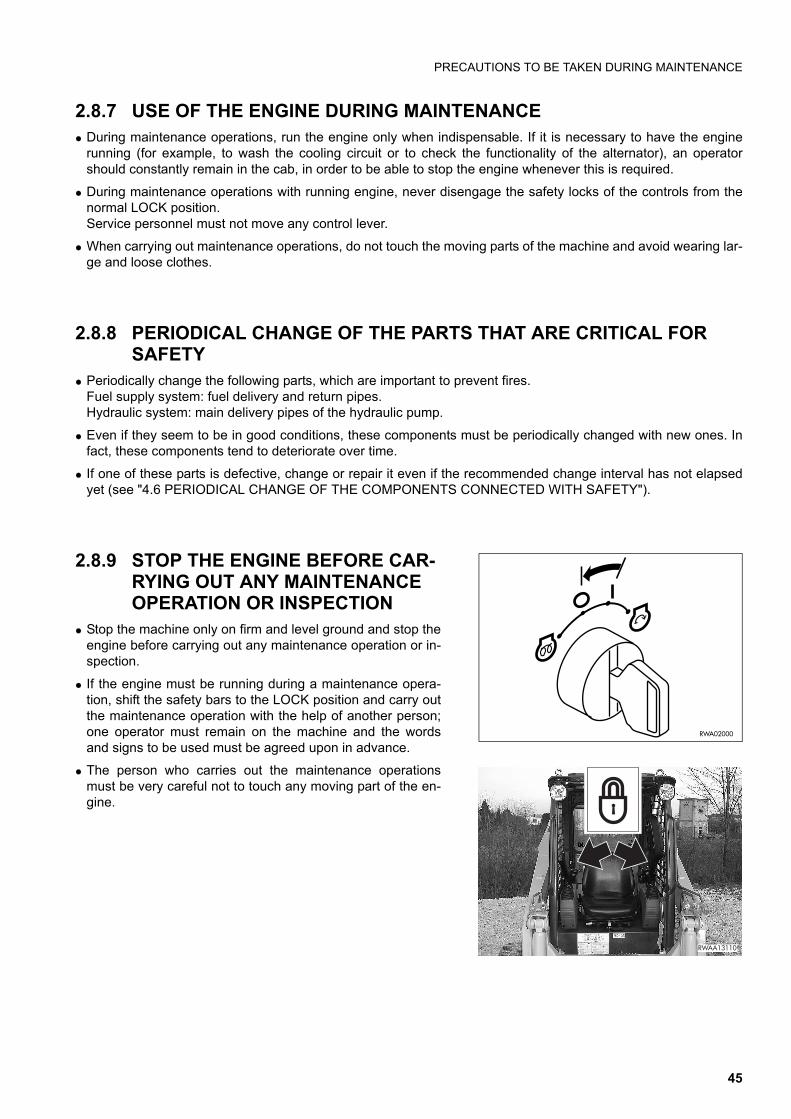
PRECAUTIONS TO BE TAKEN DURING MAINTENANCE
2.8.7 USE OF THE ENGINE DURING MAINTENANCE q During maintenance operations, run the engine only when indispensable. If it is necessary to have the engine
running (for example, to wash the cooling circuit or to check the functionality of the alternator), an operatorshould constantly remain in the cab, in order to be able to stop the engine whenever this is required.
q During maintenance operations with running engine, never disengage the safety locks of the controls from thenormal LOCK position.Service personnel must not move any control lever.
q When carrying out maintenance operations, do not touch the moving parts of the machine and avoid wearing lar-ge and loose clothes.
2.8.8 PERIODICAL CHANGE OF THE PARTS THAT ARE CRITICAL FOR SAFETY
q Periodically change the following parts, which are important to prevent fires.Fuel supply system: fuel delivery and return pipes.Hydraulic system: main delivery pipes of the hydraulic pump.
q Even if they seem to be in good conditions, these components must be periodically changed with new ones. Infact, these components tend to deteriorate over time.
q If one of these parts is defective, change or repair it even if the recommended change interval has not elapsedyet (see "4.6 PERIODICAL CHANGE OF THE COMPONENTS CONNECTED WITH SAFETY").
2.8.9 STOP THE ENGINE BEFORE CAR-RYING OUT ANY MAINTENANCE OPERATION OR INSPECTION
q Stop the machine only on firm and level ground and stop theengine before carrying out any maintenance operation or in-spection.
q If the engine must be running during a maintenance opera-tion, shift the safety bars to the LOCK position and carry outthe maintenance operation with the help of another person;one operator must remain on the machine and the wordsand signs to be used must be agreed upon in advance.
q The person who carries out the maintenance operationsmust be very careful not to touch any moving part of the en-gine.
RWA02000
���������
45

PRECAUTIONS TO BE TAKEN DURING MAINTENANCE
2.8.10 RULES FOR REFUELLING AND ADDING OIL
q Keep away from naked flames while refuelling or adding oil.
q Spilled fuel or oil make the ground slippery and may causeaccidents; clean any dirty area immediately and carefully.
q Always tighten the fuel tank and the hydraulic circuit oil sa-fety caps securely.
q Do not use fuel to clean any part of the machine that is dirtywith oil or dust.
q Always top up the fuel and oil tanks in properly ventilatedareas and refrain from smoking.
q When refuelling, hold the fuel gun firmly and keep it constan-tly in contact with the filler until you have finished, in order toavoid sparks due to static electricity.
q Do not fill the tank completely, in order to leave room for thefuel to expand.
2.8.11 CHECKING THE COOLANT LEVEL IN THE RADIATOR
q Let the engine and the radiator cool down before checkingthe coolant level.
q If it is necessary to remove the cap with hot engine, wear su-itable clothes and protections and loosen the cap slowly, inorder to release the pressure gradually.
2.8.12 USING LAMPS q Use only homologated explosion-proof lamps to check the
fuel, oil, coolant and battery electrolyte levels.Unsuitable lamps can cause fires or explosions.
RWA00970
RWA00980
RWA01340
RWA01350
46

PRECAUTIONS TO BE TAKEN DURING MAINTENANCE
2.8.13 PRECAUTIONS CONCERNING THE BATTERY AND THE ALTERNATOR
q When repairing the electrical system, disconnect the batteryin order to stop the flow of current.
IMPORTANTq Disconnect first the negative earth cable (-) and then the
positive cable (+). At the end of the operation, reconnect first the positivecable (+) and then the negative cable (-).
q If electrical welding operations are to be carried out on themachine, it is necessary to disconnect the battery and alsothe alternator.
2.8.14 PRECAUTIONS CONCERNING THE STARTER
q Do not start the engine by tampering with the terminals ofthe starter, since the machine may move.
q Sudden or accidental movements of the machine may causeserious injuries or even death.
1 2
RWA01370
REMOVAL
��������
RWA04890
������
47

PRECAUTIONS TO BE TAKEN DURING MAINTENANCE
2.8.15 PRECAUTIONS CONCERNING HIGH-PRESSURE HOSES q Do not bend high-pressure hoses or rub them with sharp or abrasive objects.
Do not use bent or cracked rigid tubes or hoses that were previously rejected because of leaks or fastening de-fects, since they may burst during use.
q Always repair or replace any loose or faulty fuel or oil pipe. Any leakage of fuel or oil may cause fires.
2.8.16 PRECAUTIONS TO BE TAKEN WHEN WORKING ON HIGH-PRES-SURE SYSTEMS
q Do not forget that the work equipment circuits are always un-der pressure; for this reason, when it is necessary to add ordrain hydraulic oil, or service or inspect the hydraulic circuit,it is advisable to lower the equipment to the ground andcompletely release the pressures and the residual pressurepresent in the tank.Small leakages from pipes under pressure and the resultingjets are extremely dangerous, since they can perforate theskin and penetrate in the blood circulation or injure the eyes. For this reason, always wear goggles and thick gloves du-ring the inspections and use a piece of cardboard or a sheetof plywood to check for oil leakages.If you are struck by a jet of high-pressure oil or are injured,even if slightly, consult a doctor immediately.
2.8.17 PRECAUTIONS FOR MAINTE-NANCE WORK INVOLVING HIGH TEMPERATURES AND PRES-SURES
q When the machine is stopped at the end of work, the enginecoolant, the oil and all the components are hot and thehydralic circuits are under pressure.In these conditions, if the coolant, the hydraulic oil and theengine oil are to be drained in order to change them or thefilters, there are serious risks of injuries and burns. Wait for the temperature to lower within the normal operatingrange (40-45ºC) before carrying out the maintenance opera-tions in accordance with the procedures indicated in the rele-vant sections of this manual.
RWA01480
DANGEROUS!
RWA01580
CORRECT
RWA00990
48

PRECAUTIONS TO BE TAKEN DURING MAINTENANCE
2.8.18 COOLING FAN AND FAN BELT q Be careful to the rotating parts and do not allow anyone to
get too close to these parts, since clothes or parts of the bo-dy may get caught into them.
q If hands, clothes, or tools get entangled in the fan blades orthe fan belt, they may be cut, torn or seriously damaged; forthis reason, avoid touching the rotating parts.
2.8.19 WASTE MATERIALS q Do not dispose of used oil in the sewer system, rivers, etc.
q Always put used oil in containers. Never drain oil directly onto the ground.
q Keep to the laws and regulations in force when disposing ofharmful substances such as oil, fuel, solvents, used filtersand batteries.
2.8.20 PRECAUTIONS TO BE TAKEN WHEN INFLATING THE TYRES
q Always bear in mind that tyres can burst while being inflated,causing serious accidents.
q Before inflating the tyres, always check the wheel rims andthe tyre walls and tread for dents, cuts, broken plies, or otherdefects.
q Have a tyre expert perform checks and tyre maintenance.
q When inflating the tyres, use a compressed air gun with ex-tension hose and pressure gauge.
q Make sure that there is nobody in the vicinity before startingto inflate a tyre. Stand at the tread or outer belt side of thetyre to inflate it.
q Never exceed the inflation pressures specified for each typeof tyre. Always make sure that the tyre pressures are identi-cal on both sides of the machine .
RWA01660
RWA01670
RWA20900
49

PRECAUTIONS TO BE TAKEN DURING MAINTENANCE
2.8.21 PRECAUTIONS TO BE TAKEN WHEN USING THE SYNTHETIC BIODE-GRADABLE OIL TYPE «HEES»
q It is not possible to mix the synthetic biodegradable oil type HEES with ordinary hydraulic oils, since when thetemperature increases insoluble compounds are generated, which are deposited on the filters and clog them(the maximum concentration of ordinary oil cannot exceed 1% of the total quantity of oil).
q The biodegradable oil can be used only in the hydraulic system; it cannot be used for the endothermic engine,the transmissions, the braking system, etc.
q Before introducing the synthetic biodegradable oil in the hydraulic system, empty the system completely, discon-necting the cylinders and all the parts that may contain ordinary oil, and replace the drain filter with a new one.Start the engine and let it idle without using the work equipment , wait until the oil reaches a temperature of at le-ast 40ºC, then start moving the equipment, so that all the parts of the system are filled with oil. Stop the engineand check the oil level (see "4.8.2.e CHECKING THE OIL LEVEL IN THE HYDRAULIC CIRCUIT").
50

�������������������� ������
51

SAFETY LOCKS
3.1 SAFETY LOCKS
DANGERq If it is necessary to stop the machine with raised loader arm, always engage the mechanical safety lock
on the arm and lock the equipment and travel control by lifting the safety bars (see "3.3.5 pos. 1 - SA-FETY BARS").
q When travelling on roads with a machine homologated for this purpose, lower the loader arm complete-ly, engage the bucket antirotation lock, apply the teeth guard and lock the equipment control by shiftingthe safety device lever to the lock position.
q When travelling on roads with a machine homologated for this purpose and equipped with excavator,fold the bucket completely, apply the lock between boom and arm, the antirotation lock between boomand sliding plate and the centre lock of the sliding plate.Raise the stabilizer supports completely, couple the relevant safety chains and finally lock the equip-ment control by shifting the safety device lever to the lock position. If the machine is also equipped withrear stabilizers, raise the supports and lock them with the relevant safety chains.
q When travelling on roads with a machine homologated for this purpose and equipped with asphalt cut-ter, apply the lock on the lifting jack in order to keep the equipment at a given distance from the ground,lower the loader arm completely, install the antirotation lock of the front equipment and finally lock theequipment control by shifting the safety device lever to the lock position.
q Non-compliance with these rules may lead to serious accidents.
3.1.1 LOADER LOCKS q The loader arm is provided with a safety lock (1) to be used
to keep the arm raised when the machine is serviced or rou-tine operations are carried out.
q The engagement of the safety lock must be carried out bytwo persons, one seated in driving position to check themovements of the machine and the other standing on theground to engage the lock correctly.
q It is important to remember that in operating conditions thesafety lock (1) must be positioned against the arm and keptin this position by means of the safety pin (2).
DANGERq After engaging the lock (1), fasten it with the safety pin
(2) held by the split pin (3).q Do not carry out any operation under the raised loader
arm if the safety lock (1) has not been engaged.
IMPORTANTq Always open the engine hood (see "3.5.1 ENGINE
HOOD") before lifting the loader arm.q The safety lock must always adhere to the hydraulic cyl-
inder rod.q The safety lock must be brought to its definitive position
by moving the contact surfaces slowly and continuous-ly, in such a way as not to damage the cylinder head sur-face.
��
��������
�
�
��������
�
52
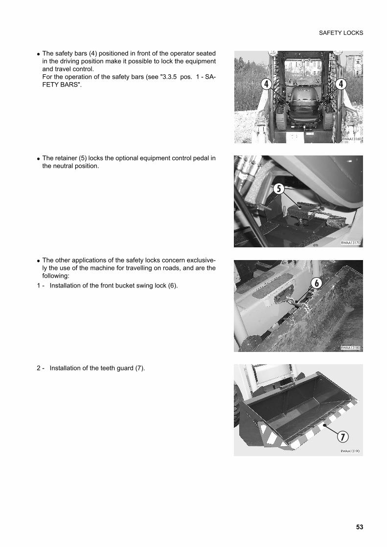
SAFETY LOCKS
q The safety bars (4) positioned in front of the operator seatedin the driving position make it possible to lock the equipmentand travel control.For the operation of the safety bars (see "3.3.5 pos. 1 - SA-FETY BARS".
q The retainer (5) locks the optional equipment control pedal inthe neutral position.
q The other applications of the safety locks concern exclusive-ly the use of the machine for travelling on roads, and are thefollowing:
1 - Installation of the front bucket swing lock (6).
2 - Installation of the teeth guard (7).
���������
� �
��������
�
��������
�
����������
53

SAFETY LOCKS
3 - Locking of the safety device (8) for the inhibition of theequipment control.
3.1.2 EXCAVATOR LOCKS (if installed)IMPORTANTq When travelling on roads, always position the excavator
following the longitudinal axis of the vehicle, apply thesafety locks and lock the equipment control by shiftingthe safety device lever to the lock position.
The excavator safety locks must be used for travelling onroads and applied by proceeding as follows.
q After folding the bucket completely, apply the lock (1) be-tween boom and arm, the connection lock (2) between boomand sliding plate, the centre pin (3) that locks the slidingplate on the frame, raise the stabilizer supports completelyand engage the relevant safety chains (4).
���������
�
RWA37410
RWA23280
1
23
4
54

SAFETY LOCKS
q If the machine is equipped with rear stabilizers, raise thesupports completely and engage the relevant safetychainsza (5).
���� � �
�
�
���� ��
���� ���
�
���� ���
�
RWA37420
5
55

SAFETY LOCKS
3.1.3 ASPHALT CUTTER LOCKS (if installed)
IMPORTANTq When travelling on roads, always position the asphalt
cutter following the longitudinal axis of the vehicle, ap-ply the safety locks and lock the equipment control byshifting the safety device lever to the lock position.
q If the machine is equipped with asphalt cutter, besides ap-plying the antirotation lock already described for the stand-ard machine (see "3.1.1 LOADER LOCKS"), it is alsonecessary to apply the lock (1) on the lifting jacks, in such away as to keep the equipment at a given distance from theground.
���� ���
���� ���
�
56

GENERAL VIEWS
3.2 GENERAL VIEWS
3.2.1 FRONT GENERAL VIEW
1 Bucket 4 Frame2 Bucket cylinder 5 Arm3 Wheels 6 Cab
RWA37430
1
2
3
4
5
2
6
57

GENERAL VIEWS
3.2.2 REAR GENERAL VIEW
1 Rear panel 3 Lifting cylinder2 Engine hood 4 Exhaust silencer
RWA37440
3
1
2
4
58

GENERAL VIEWS
3.2.3 CAB INSIDE GENERAL VIEW
1 - Safety bars2 - Left servo control lever
- (ISO PATTERN) - travel and steering- (OPTION PATTERN) - left wheel travel and loader arm
control 3 - Right servo control lever
- (ISO PATTERN) - loader arm and bucket control- (OPTION PATTERN) - right wheel travel and bucket con-
trol 4 - Auxiliary hydraulic kit control pedal (if installed)5 - Foot accelerator 6 - Hand accelerator 7 - Parking brake8 - Equipment control locking lever (if installed)9 - Dashboard
RWA31880
11
2 3
7
4 5
6
�
��������
���������
�
59

GENERAL VIEWS
10 - Left console switches11 - Right console switches
�������
��
���������
�
60

INSTRUMENTS AND CONTROLS
3.3 INSTRUMENTS AND CONTROLS
3.3.1 INSTRUMENTS
1 - HOUR METER This instrument indicates the total number of operating hoursof the engine. The count is continuous and the number is in-creased by 1 when the engine has run for one hour, independ-ently of its speed. When the engine is running, the led (A)positioned under the instrument flashes for the count of theseconds.The hour meter keeps functioning even if the machine is nottravelling or working.The reading of the hour meter is to be considered valid for thecalculation of the maintenance intervals.
1 Hour meter 3 Fuel level indicator2 Engine coolant temperature indicator
RWA31900
F
H
C
EP
1 2 3
RYA13640
61

INSTRUMENTS AND CONTROLS
2 - ENGINE COOLANT TEMPERATURE INDICATOR This instrument indicates the temperature of the engine cool-ant, which in normal conditions should be 80-85°C.After starting the engine and before starting work, let it warmup until the temperature indicator reaches the green range.If the indicator exceeds the limit values while the engine is run-ning and reaches the overheating red range, let the engineidle until the indicator returns to the normal temperature greenrange.
When the indicator reaches the overheating red range, theacoustic alarm sounds, too.If this inconvenience occurs repeatedly, try to find out thecause (see TROUBLESHOOTING "3.15.4.3 ENGINE").
3 - FUEL LEVEL INDICATOR This instrument indicates the fuel level in the tank; this infor-mation is available only with the ignition key in position «I»(see "3.3.3 pos. 9 - IGNITION SWITCH").The green range indicates the normal fuel level, while the redrange indicates that the fuel level is low.
NOTEq If the indicator reaches the reserve red range while the ma-
chine is working, stop it and refuel it up to the correct level.
RYA13650
RYA13660
RYA13670
62

INSTRUMENTS AND CONTROLS
3.3.2 WARNING LIGHTS
1 - GENERATOR WARNING LIGHT This warning light comes on when the starting circuit is ener-gized and goes out when the engine exceeds the idling speed;if this warning light remains on even when the engine is run-ning at the normal operating speed, this means that the alter-nator does not work and the battery is not charged correctly.
NOTEq If the warning light remains off when the ignition key is
turned to position «I» this means that the alternator is faultyor broken.
1 Generator warning light 7 Speed increase warning light2 Preheating warning light 8 Floating device warning light3 Engine oil pressure warning light 9 Direction indicator warning light4 Air cleaner clogging warning light 10 Working light warning light5 Hydraulic oil filter clogging warning light 11 Safety device functionality control unit6 Parking brake warning light
RWA31890
F
H
C
EP
1 325
6 9 107 8
4
11
RWA07150
63

INSTRUMENTS AND CONTROLS
2 - PREHEATING WARNING LIGHT This warning light comes on when the ignition key is turned toposition « » to start the engine at low temperatures andgoes out automatically after approximately 13 seconds (see"3.6.2.2 STARTING WITH COLD ENGINE OR IN COLD CLI-MATES").
3 - ENGINE OIL PRESSURE WARNING LIGHT This warning light comes on and activates the acoustic alarmwith engine at rest when the starting circuit is energized andgoes out as soon as the engine lubrication circuit is pressu-rized.If this warning light remains on or comes on with the enginerunning, stop the machine immediately and try to locate thetrouble.
4 - AIR CLEANER CLOGGING WARNING LIGHT This warning light comes on when the engine air filter needscleaning.
5 - HYDRAULIC OIL FILTER CLOGGING WARNING LIGHT This warning light comes on when the hydraulic circuit filterneeds replacing.
RWA07160
RWA07130
RWA31710
RWA22340
64

INSTRUMENTS AND CONTROLS
6 - PARKING BRAKE WARNING LIGHT This warning light comes on when the parking brake circuitisn't pressurised (brake applied).If the warning light comes on during routine operations, stopthe machine and try to locate the cause of the malfunction.
7 - SPEED INCREASE WARNING LIGHT It comes on when the high speed is selected (see "3.3.3 pos.13 - SPEED INCREASE BUTTON").
8 - FLOATING DEVICE WARNING LIGHT It comes on when the floating device is connected (see "3.3.3pos. 14 - FLOATING DEVICE SWITCH (if installed)").
9 - DIRECTION INDICATOR WARNING LIGHT This warning light comes on intermittently when the lever onthe dashboard is operated (see "3.3.3 pos. 8 - DIRECTIONINDICATOR SWITCH") or when the emergency switch is oper-ated (see «"3.3.3 pos. 6 - EMERGENCY SWITCH (HA-ZARD)").
RWA20230
P
RWA18440
RWA23300
RWA20200
65

INSTRUMENTS AND CONTROLS
10 - WORKING LIGHT WARNING LIGHT It comes on when the working lights are turned on with theswitch positioned on the dashboard (see "3.3.3 pos. 5 -WORKING LIGHT SWITCH").
11 - SAFETY DEVICE FUNCTIONALITY CONTROL UNIT This control unit is positioned on the dashboard and checksthe condition of the safety devices installed on the machine.The signals are shown on the display by the coming on andgoing out of the warning lights.
The functions are the following:
A - RED WARNING LIGHTLED off - This means that all the safety devices are onand therefore all the machine functions are normal (thesolenoid valve ensures the lifting of the work equipmentand the machine travel).LED on - This means that at least one safety function islacking; in this case the solenoid valve is closed and doesnot permit the lifting and therefore the use of the workequipment and the machine travel.
B - GREEN WARNING LIGHTLED on - This means that the operator is correctly seatedin the driving position and that the operator presence sen-sor is on.LED off - (With the red warning light coming on at thesame time) This means that the operator is standing orthat he is not inside the cab.
NOTEq The operator presence signal (seat) starts the emergency
condition with a delay of 1.5 seconds.With this solution the operatorís jerks (especially when work-ing on uneven ground) are sensed without signalling repeat-ed emergencies.
RWA07180
RWA31910
C
E
A
B C
RWA22370
A
RWA22380
B
66
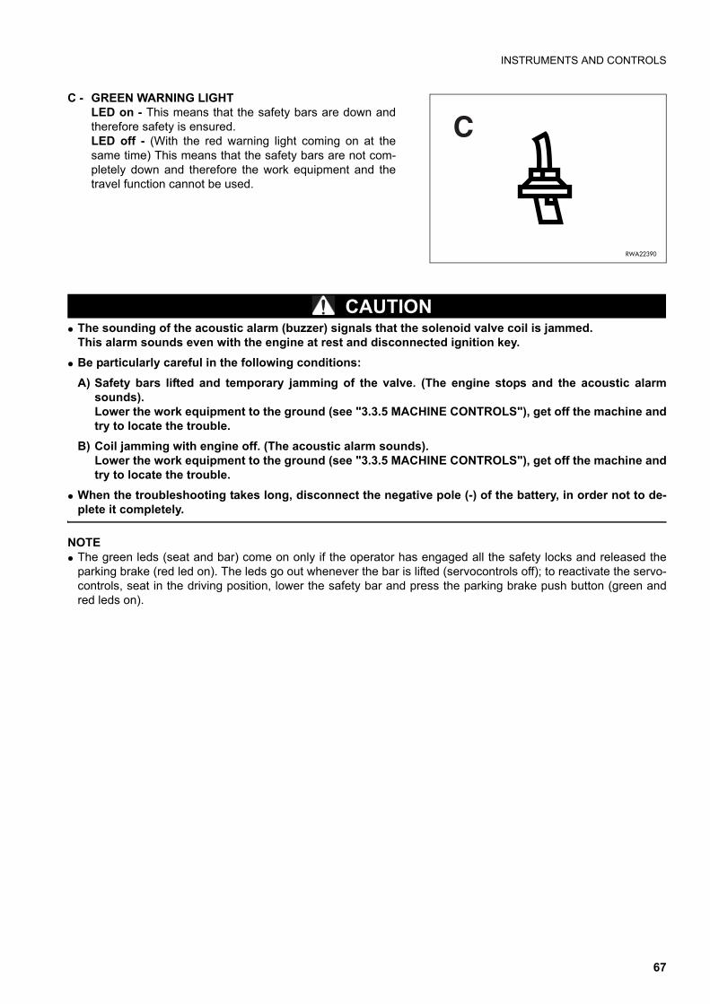
INSTRUMENTS AND CONTROLS
C - GREEN WARNING LIGHTLED on - This means that the safety bars are down andtherefore safety is ensured.LED off - (With the red warning light coming on at thesame time) This means that the safety bars are not com-pletely down and therefore the work equipment and thetravel function cannot be used.
CAUTIONq The sounding of the acoustic alarm (buzzer) signals that the solenoid valve coil is jammed.
This alarm sounds even with the engine at rest and disconnected ignition key.q Be particularly careful in the following conditions:
A) Safety bars lifted and temporary jamming of the valve. (The engine stops and the acoustic alarmsounds).Lower the work equipment to the ground (see "3.3.5 MACHINE CONTROLS"), get off the machine andtry to locate the trouble.
B) Coil jamming with engine off. (The acoustic alarm sounds).Lower the work equipment to the ground (see "3.3.5 MACHINE CONTROLS"), get off the machine andtry to locate the trouble.
q When the troubleshooting takes long, disconnect the negative pole (-) of the battery, in order not to de-plete it completely.
NOTEq The green leds (seat and bar) come on only if the operator has engaged all the safety locks and released the
parking brake (red led on). The leds go out whenever the bar is lifted (servocontrols off); to reactivate the servo-controls, seat in the driving position, lower the safety bar and press the parking brake push button (green andred leds on).
RWA22390
C
67

INSTRUMENTS AND CONTROLS
3.3.3 SWITCHES UND PUSH BUTTONS1 - Parking brake push button2 - Revolving light switch3 - Left stabilizer button (if installed)4 - Right stabilizer button (if installed)5 - Working light switch6 - Emergency switch (HAZARD)7 - Parking light and low beam switch8 - Direction indicator switch 9 - Ignition switch10 - Horn11 - "High flow" hydraulic system switch (3 lines)
for front equipment (if installed)
���������
�� ��
����� �
����
������� �
� ��
��
�������
68

INSTRUMENTS AND CONTROLS
12 - “Super flow" hydraulic system switch (5 lines)for front equipment (if installed)
13 - Speed increase button 14 - Floating device button (if installed)15 - Available for other functions
1 - PARKING BRAKE PUSH BUTTON When pressed, this button comes on and applies the parkingbrake.When pressed again (LED off), it releases the parking brake.
NOTEq The parking brake is automatically engaged whenever the
engine stops; this is due to the lack of pressure in the hy-draulic circuit.
q The push button releases the brake only when the engine isrunning and all the safety devices are in function (warninglights off).
2 - REVOLVING LIGHT SWITCHSwitches on the revolving light and must be operated when itis necessary to travel on roads.
���������
� ��
��
���������
��
��
��
RWA20230
P
RWA07210
69

INSTRUMENTS AND CONTROLS
3 - LEFT STABILIZER BUTTON (if installed)This is a button with two temporary positions and the neutralposition at its centre.Press the button forward or backward to lower or raise the sta-bilizer.
For use, see "3.3.5 pos. 14 - LEFT STABILIZER CONTROL(IF INSTALLED)".
4 - RIGHT STABILIZER BUTTON (if installed)This is a button with two temporary positions and the neutralposition at its centre.Press the button forward or backward to lower or raise the sta-bilizer.For use, see "3.3.5 pos. 13 - RIGHT STABILIZER CONTROL(IF INSTALLED)".
5 - WORKING LIGHT SWITCH Enables the circuit of the working lights.
6 - EMERGENCY SWITCH (HAZARD)Operates all the direction lights at the same time and must beused whenever the machine is temporarily parked on the road-side or in anomalous position while travelling on roads.
RWA23320
RWA23310
RWA07180
RWA20210
70

INSTRUMENTS AND CONTROLS
7 - PARKING LIGHT AND LOW BEAM SWITCH This is a two-position switch:
The 1st click enables the circuit of the instrument lights and theparking lights.
The 2nd click enables the general circuit of the low beam orworking lights, according to the position of the switch (2).
8 - DIRECTION INDICATOR SWITCH This is a lever switch with three positions. The neutral positionis at the centre.Shift the switch lever to the right or to the left to indicate theturn direction.
9 - IGNITION SWITCH This is a rotary key switch with four positions marked by thefollowing symbols « » - (OFF) - I - « » (START).For further details on the use of this switch, see "3.6.2 STAR-TING THE ENGINE".
10 - HORN This push button is positioned on the left lever grip and servesto warn the persons in the vicinity of the machine at the begin-ning of work and in case of danger.
RWA22400
RWA20200
RWA23290
RWA20870
71
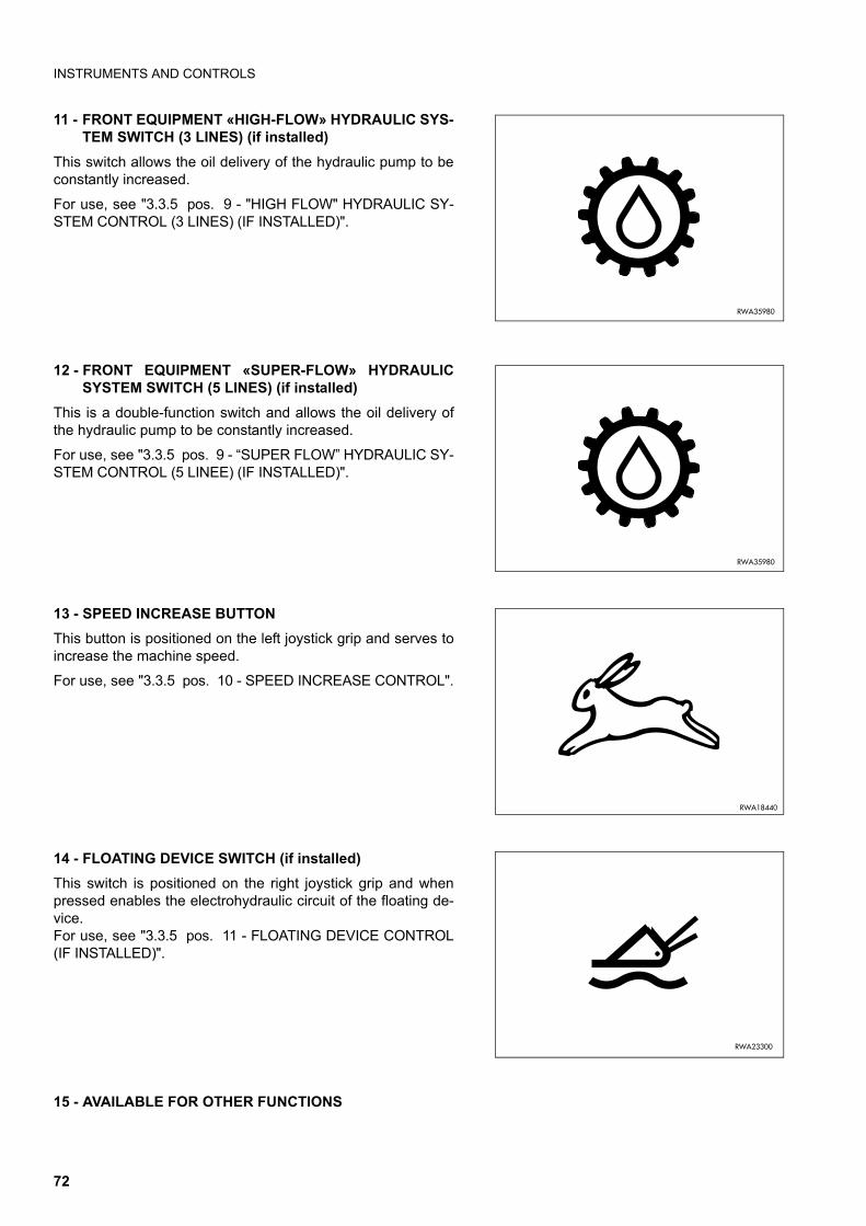
INSTRUMENTS AND CONTROLS
11 - FRONT EQUIPMENT «HIGH-FLOW» HYDRAULIC SYS-TEM SWITCH (3 LINES) (if installed)
This switch allows the oil delivery of the hydraulic pump to beconstantly increased.
For use, see "3.3.5 pos. 9 - "HIGH FLOW" HYDRAULIC SY-STEM CONTROL (3 LINES) (IF INSTALLED)".
12 - FRONT EQUIPMENT «SUPER-FLOW» HYDRAULICSYSTEM SWITCH (5 LINES) (if installed)
This is a double-function switch and allows the oil delivery ofthe hydraulic pump to be constantly increased.
For use, see "3.3.5 pos. 9 - “SUPER FLOW” HYDRAULIC SY-STEM CONTROL (5 LINEE) (IF INSTALLED)".
13 - SPEED INCREASE BUTTON This button is positioned on the left joystick grip and serves toincrease the machine speed.
For use, see "3.3.5 pos. 10 - SPEED INCREASE CONTROL".
14 - FLOATING DEVICE SWITCH (if installed)This switch is positioned on the right joystick grip and whenpressed enables the electrohydraulic circuit of the floating de-vice. For use, see "3.3.5 pos. 11 - FLOATING DEVICE CONTROL(IF INSTALLED)".
15 - AVAILABLE FOR OTHER FUNCTIONS
RWA35980
RWA35980
RWA18440
RWA23300
72

INSTRUMENTS AND CONTROLS
3.3.4 ELECTRICAL ACCESSORIES 1 - Acoustic alarm2 - Electric outlet3 - Accumulator disconnection switch (if provided)
1 - ACOUSTIC ALARM This acoustic alarm sounds when the circuits are energizedwith the ignition key (rotation to position ìIî) and is automatical-ly disconnected when the engine is started.The sounding of the alarm during operation signals:
q insufficient engine oil pressure;
q overheating of the engine cooling circuit;
q jamming of the servo control solenoid valve coil
�������
�
��������
�
������ �
�
RWA07200
73

INSTRUMENTS AND CONTROLS
2 - ELECTRIC OUTLET An electric outlet is positioned on the right side of the cab innerwall for the connection of a lighting device for routine andmaintenance operations.It is a two-pole outlet and is in compliance with the ISO 4165-1979 standard.Power supply 12 V.
3 - ACCUMULATOR DISCONNECTION SWITCH (if provided)
This is a removable lever-type switch positioned near the ac-cumulator; to reach it, it is necessary to open the engine hood(see "3.5.1 ENGINE HOOD").The current transmitted by the accumulator to the electric sys-tem of the machine can be interrupted by rotating the switchclockwise (position B).Always rotate the switch to “position B” if it is necessary towork on the accumulator or the electric system, or if electricwelds must be carried out on the machine.The electric contact can be restored by rotating the switch an-ticlockwise (position A).
RWA07250
������ ��
�
���������
�
74

INSTRUMENTS AND CONTROLS
3.3.5 MACHINE CONTROLS
CAUTIONq The procedures to be followed to use any control systems different from the ISO and OPTION PATTER-
NS are described in section "OPTIONAL EQUIPMENT" (See "6.5 HAND & FOOT CONTROL SYSTEM").Carefully read and be sure to understand the contents of this section before using the machine.
1 - Safety bars2 - Left servo control lever
- (ISO PATTERN) - travel and steering- (OPTION PATTERN) - left wheel travel and loader arm
control 3 - Right servo control lever
- (ISO PATTERN) - loader arm and bucket control- (OPTION PATTERN) - right wheel travel and bucket con-
trol 4 - Auxiliary hydraulic kit control pedal (if installed)5 - Foot accelerator 6 - Hand accelerator 7 - Parking brake8 - Equipment control locking lever (if installed)9 - "High flow" hydraulic system control (3 lines) (if installed)
- "Super flow" hydraulic system control (5 lines) (if installed)10 - Speed increase control
RWA31880
11
2 3
7
4 5
6
���������
�
���������
�
75

INSTRUMENTS AND CONTROLS
11 - Floating device control (if installed)12 - Pattern shifting control (if installed)13 - Right stabilizer control (if installed)14 - Left stabilizer control (if installed)15 - Optionals
������ ��
��
�����������
RWA36000
14 13
���������
��
��
76

INSTRUMENTS AND CONTROLS
1 - SAFETY BARS
WARNINGq Before leaving the operating position, lower the equip-
ment to the ground and lock the safety bars.q The safety devices of the machine are composed of
electric parts.Therefore, before modifying or replacing wirings andelectrical components, which may result in malfunc-tions of the devices, contact your Komatsu Dealer.
The locking of the servo control safety device is obtained bylifting the bars (1) in vertical position.The safety device can be released by lowering the bars to thehorizontal position and pressing the parking brake push button(warning light off).
NOTEq The equipment movements and the travel function are inhib-
ited when the safety bars (1) are locked.
���������
� �
���������
� �
77

INSTRUMENTS AND CONTROLS
ISO PATTERN CONTROL SYSTEM
CAUTIONq The procedures to be followed to use any control systems different from the ISO and OPTION PATTER-
NS are described in section "OPTIONAL EQUIPMENT" (See "6.5 HAND & FOOT CONTROL SYSTEM").Carefully read and be sure to understand the contents of this section before using the machine.
2 - LEFT SERVO CONTROL LEVER (TRAVEL AND STEERING)
WARNINGq Before carrying out any manoeuvre with this lever, the operator must be seated in the work position with
fastened safety belt; before every manoeuvre the operator must take all the precautions indicated "3.6.5HOW TO MOVE THE MACHINE (ISO PATTERN CONTROL SYSTEMERN)".
q Before moving, make sure that the parking brake is disengaged.q When travelling on roads, make sure that all the safety devices have been engaged.q Failure to comply with these rules may lead to serious accidents.
The travel control lever (2) is positioned on the operatorís leftand serves to control the forward and reverse movements andthe steering of the machine, according to the movements indi-cated in the diagram.
N - NeutralA - Forward gearB - Counterrotation to the rightC - Reverse gearD - Counterrotation to the left
������
�
RWA22410
D
A
B
C
N
F
R
78

INSTRUMENTS AND CONTROLS
If the lever is operated in directions that are inclined with re-spect to the machine axis, simultaneous steering movementsproportional to the angle of inclination are obtained, since thetwo hydraulic pumps corresponding to each single function areengaged at the same time.
N - NeutralA - Forward left steeringB - Forward right steeringC - Reverse left steeringD - Reverse right steering
CAUTIONq Always travel at moderate speed, in order to obtain maximum precision and maximum efficiency during
work.q During work, the use of the lever must be proportional to the required effort and such as to obtain con-
stant engine speed.q Manoeuvre the lever smoothly, without abrupt movements and avoid counterrotations as much as pos-
sible, since these manoeuvres involve untimely wear of the tyres.
NOTEq The lever grip is provided with the horn, which must be used to warn the persons in the vicinity of the machine at
the beginning of work and in case of danger.
q To inhibit all movements, lock the controls by lifting the safety bars in vertical position "3.3.5 pos. 1 - SAFETYBARS").
RWA22420
D
A B
CN
79

INSTRUMENTS AND CONTROLS
3 - RIGHT SERVO CONTROL LEVER (LOADER ARM AND BUCKET)
WARNINGq Before carrying out any manoeuvre with this lever, the operator must be seated in the work position with
fastened safety belt; before any manoeuvre he must perform the operations described in"3.13 USINGTHE WORK EQUIPMENT".
q When travelling on roads, always lock the equipment control (see "3.3.5 pos. 8 - EQUIPMENT CONTROLLOCKING LEVER (IF INSTALLED)").
q Before leaving the operating position, lower the equipment to the ground and lock the safety bars (verti-cal position), then stop the engine.
q Failure to comply with these instructions may lead to serious accidents.
CAUTIONq The self-leveling system is operated automatically only when the loader arm is lifted with loaded bucket.
When the arm is in the lowering phase the system cannot be operated.q At the maximum height the self-leveling system keeps the bucket partially folded to prevent the material
from falling out of the bucket itself.
The equipment control lever (3) is positioned on the operatorísright and controls the loader arm lifting and lowering and thebucket dumping and folding functions.The following diagrams show the basic manoeuvres and thepossible combined manoeuvres.
BASIC MANOEUVRES N - NeutralA - Loader arm loweringB - Bucket dumpingC - Loader arm liftingD - Bucket folding
�������
�
RWA22430
D
A
B
C
N
80

INSTRUMENTS AND CONTROLS
If the lever is operated in directions that are inclined with re-spect to the machine axis, simultaneous movements propor-tional to the angle of inclination are obtained, since the twohydraulic distributors corresponding to each single functionare engaged at the same time.
COMBINED MANOEUVRES N - NeutralA - Loader arm lowering - Bucket folding B - Loader arm lowering - Bucket opening C - Loader arm lifting - Bucket opening D - Loader arm lifting - Bucket folding
NOTEq To inhibit all movements, lock the controls by lifting the safe-
ty bars in vertical position . (see "3.3.5 pos. 1 - SAFETYBARS").
RWA22440
D
A B
C
N
81

INSTRUMENTS AND CONTROLS
OPTIONAL PATTERN CONTROL SYSTEM
CAUTIONq The procedures to be followed to use any control systems different from the ISO and OPTION PATTER-
NS are described in section "OPTIONAL EQUIPMENT" (See "6.5 HAND & FOOT CONTROL SYSTEM").Carefully read and be sure to understand the contents of this section before using the machine
2 - LEFT SERVO CONTROL LEVER (LEFT WHEEL TRAVEL AND LOADER ARM CONTROL)
WARNINGq Before carrying out any manoeuvre with this lever, the operator must be seated in the work position with
fastened safety belt; before every manoeuvre the operator must take all the precautions indicated in"3.6.6 HOW TO MOVE THE MACHINE (OPTIONAL PATTERN CONTROL SYSTEM)" and "3.13 USING THEWORK EQUIPMENT".
q Before moving, make sure that the parking brake is disengaged.q When travelling on roads, always lock the equipment control (see "3.3.5 pos. 8 - EQUIPMENT CONTROL
LOCKING LEVER (IF INSTALLED)".q When travelling on roads, make sure that all the safety devices have been engaged.q Before leaving the work position, lower the equipment to the ground and lock the safety bars (vertical
position), then stop the engine.q Failure to comply with these rules may lead to serious accidents.
CAUTIONq The self-leveling system is operated automatically only when the loader arm is lifted with loaded bucket.
When the arm is in the lowering phase the system cannot be operated.q At the maximum height the self-leveling system keeps the bucket partially folded to prevent the material
from falling out of the bucket itself.
The servo control lever (2) is positioned on the Operator's leftand controls the forward and reverse movements of the ma-chine, as weel as the steering to the right and the lifting andlowering of the loader arm according to the movements indica-ted in the diagram.
IMPORTANTq To move the machine forward or backward, shift the
control levers (2) and (3) at the same time and in thesame direction.
������
�
�������
�
82

INSTRUMENTS AND CONTROLS
N - NeutralA - Forward right steering B - Loader arm lowering C - Reverse right steering D - Loader arm lifting
CAUTIONq Always travel at moderate speed, in order to obtain maximum precision and maximum efficiency during
work.q During work, the use of the lever must be proportional to the required effort and such as to obtain con-
stant engine speed.q Manoeuvre the lever smoothly, without abrupt movements and avoid counterrotations as much as pos-
sible, since these manoeuvres involve untimely wear of the tyres.
NOTEq The lever grip is provided with the horn, which must be used to warn the persons in the vicinity of the machine at
the beginning of work and in case of danger.
q To inhibit all movements, lock the controls by lifting the safety bars in vertical position "3.3.5 pos. 1 - SAFETYBARS").
RWA32220
D
A
B
C
N
F
R
83

INSTRUMENTS AND CONTROLS
3 - RIGHT SERVO CONTROL LEVER (RIGHT WHEEL TRAVEL AND BUCKET FOLDING)
WARNINGq Before carrying out any manoeuvre with this lever, the operator must be seated in the work position with
fastened safety belt; before every manoeuvre the operator must take all the precautions indicated in"3.6.6 HOW TO MOVE THE MACHINE (OPTIONAL PATTERN CONTROL SYSTEM)" and "3.13 USING THEWORK EQUIPMENT".
q Before moving, make sure that the parking brake is disengaged.q When travelling on roads, always lock the equipment control (see "3.3.5 pos. 8 - EQUIPMENT CONTROL
LOCKING LEVER (IF INSTALLED)").q When travelling on roads, make sure that all the safety devices have been engaged.q Before leaving the work position, lower the equipment to the ground and lock the safety bars (vertical
position), then stop the engine.q Failure to comply with these rules may lead to serious accidents.
The servo control lever (3) is positioned on the Operator's rightand controls the forward and reverse movements of the ma-chine, as weel as the steering to the left and the bucket foldingand dumping according to the movements indicated in the dia-gram.
IMPORTANTq To move the machine forward or backward, shift the
control levers (2) and (3) at the same time and in thesame direction
N - NeutralA - Forward left steering B - Bucket dumping C - Reverse left steering D - Bucket folding
�������
�
������
�
RWA32230
D
A
B
C
N
R
F
84

INSTRUMENTS AND CONTROLS
CAUTIONq Always travel at moderate speed, in order to obtain maximum precision and maximum efficiency during
work.q During work, the use of the lever must be proportional to the required effort and such as to obtain con-
stant engine speed.q Manoeuvre the lever smoothly, without abrupt movements and avoid counterrotations as much as pos-
sible, since these manoeuvres involve untimely wear of the tyres.
NOTEq To inhibit all movements, lock the controls by lifting the safety bars in vertical position (see "3.3.5 pos. 1 - SA-
FETY BARS").
85

INSTRUMENTS AND CONTROLS
4 - AUXILIARY HYDRAULIC KIT CONTROL PEDAL(IF INSTALLED)
CAUTIONq The procedures to be followed to use any control sy-
stems different from the ISO and OPTION PATTERNSare described in section "OPTIONAL EQUIPMENT" (See"6.5 HAND & FOOT CONTROL SYSTEM"). Carefully readand be sure to understand the contents of this sectionbefore using the machine.
WARNINGq Always apply the safety guard (2) when the use of this
control is not required, during travel and when parkingthe machine.
q When installing any hydraulic control equipment, makesure that the control pedal (1) is always in neutral posi-tion and covered by the safety guard (2).
q Never set the control pedal in the "maximum flow" posi-tion (B), unless the machine is stationary, with raised sa-fety bars, and the operator is seated in driving positionwith fastened safety belt.
The pedal (1) controls the opening and closing of the oil flow tothe equipment and has three fixed positions (left, neutral, ri-ght).
NOTEq To use the pedal (1), lift the safety guard (2).
1 - Neutral position (A) (HYDRAULIC CIRCUIT CLOSED).When the pedal is in this position, it isn't possible to usethe optional equipment in any way.
2 - Pressed pedal (B) (HYDRAULIC CIRCUIT OPEN)When the pedal is pressed with the left side of the footand locked in this position with the lever (3), a continuousoil flow is delivered to the equipment (excavator, demoli-tion hammer, asphalt cutter, etc.).To release the pedal (1) and set it in neutral or horizontalposition, push the locking lever (3) forward as indicated inthe figure (A).
3 - Bidirectional flow position.The pedal is also used to control the oil flow to the equip-ment with bidirectional hydraulic circuit (multi-purposebuckets, drills, asphat cutters, etc.). Shift the locking lever(3) to the release position and press the pedal (1) to posi-tion L or R to control the oil flow to the equipment. Thequantity of oil conveyed in each direction is proportional tothe pressure exerted on the pedal.
����� �
�
���������
�
�
�
�
�
�
�������
�
��������
�
�
�
86

INSTRUMENTS AND CONTROLS
5 - FOOT ACCELERATOR The accelerator pedal (1) is positioned on the operator’s rightand serves to control the engine speed and power.Use the accelerator pedal with care, especially when the ma-chine is under strain or is working in difficult conditions. Avoid useless accelerations, in order to reduce consumptionand extend the life of both the engine and the machine.
6 - HAND ACCELERATOR
WARNINGq The use of the hand accelerator is allowed only under
the indicated conditions; its use in other conditions maylead to accidents.
The hand accelerator must be used during the warming up ofthe engine and successively when operations with the optionalequipment are to be carried out; it can also be used for somemaintenance operations.
q Idling position (A):lever completely pushed forward.
q Maximum speed position (B):lever completely pulled backward.
�
��������
�������
�
��������
�
87

INSTRUMENTS AND CONTROLS
7 - PARKING BRAKE
WARNINGq The parking brake must be applied whenever the opera-
tor leaves the driving position, even if for a short time.q The machine must be positioned with the wheels resting
firmly on the ground. If one of the wheels is unstable oris resting on a small obstacle, the machine may move.
q Periodically check the functionality of the parking brake.Failure to comply with these instructions may lead toserious accidents or even death.
q In case of failure of the hydraulic system, before the re-covery of the machine release the negative brake in-stalled on the travel hydraulic motors (see "4.8.1.dRELEASING THE PARKING BRAKE").
The braking action is obtained by pressing the switch (1) (LEDON); the release is obtained by pressing the switch again(LED OFF).
IMPORTANTq The parking brake is automatically engaged whenever
the engine stops; this is due to the lack of pressure inthe hydraulic system.
q Every time the engine is started or restarted, it is neces-sary to release the parking brake before moving the ma-chine.
8 - EQUIPMENT CONTROL LOCKING LEVER (IF INSTALLED)
WARNINGq When travelling on roads, always lock the equipment
control.
When shifted to the lock position, the lever inhibits the equip-ment control.Before travelling on roads, always lock the equipment control.The positions of use of the lever are those indicated in the fig-ures.
�
������ ��
���������
���������
88

INSTRUMENTS AND CONTROLS
9 - STANDARD FLOW HYDRAULIC SYSTEM CONTROL(2 LINES)
WARNINGq Avoid connecting any equipment to the hydraulic lines
before said equipment has been correctly installed froma mechanical point of view and secured to the machinefront coupling.
q Avoid connecting any manually-controlled equipment ortool (for example, hand hammer) to the hydraulic lineswhile the equipment/tool is working.
q Connect the hydraulic lines only with the engine off andthe parking brake applied.
q To avoid serious injury, always operate the equipmentwhile seated in driving position. Do not allow anyone toget too close the machine or the equipment.
q Read the contents of the equipment instruction manualcarefully before using the machine or carrying out main-tenance operations.
The bidirectional oil flow to the equipment is controlled by thepedal (A) (see "3.3.5 pos. 4 - AUXILIARY HYDRAULIC KITCONTROL PEDAL (IF INSTALLED)") and is proportional tothe pressure exerted on the pedal in both directions. Thehydraulic lines are positioned on the left side of the arm.
����� ��
�
������ ��
89

INSTRUMENTS AND CONTROLS
9 - "HIGH FLOW" HYDRAULIC SYSTEM CONTROL (3 LINES) (IF INSTALLED)
WARNINGq Avoid connecting any equipment to the hydraulic lines
before said equipment has been correctly installed froma mechanical point of view and secured to the machinefront coupling.
q Avoid connecting any manually-controlled equipment ortool (for example, hand hammer) to the hydraulic lineswhile the equipment/tool is working.
q Connect the hydraulic and electric lines only with theengine off and the parking brake applied.
q To avoid serious injury, always operate the equipmentwhile seated in driving position. Do not allow anyone toget too close the machine or the equipment.
q Read the contents of the equipment instruction manualcarefully before using the machine or carrying out main-tenance operations.
IMPORTANTq When the HIGH FLOW hydraulic button (1) is pressed,
the flow conveyed to the hydraulic connections positio-ned on the left side of the loader arm for the operation ofthe equipment is higher than the standard flow.
DANGERq If the engine is running and the parking brake isn't ap-
plied, when the HIGH FLOW button (1) is pressed theLED on the button comes on and the hydraulic oil flowrate through the front auxiliary rapid couplings is high.
q The HIGH FLOW hydraulic system can be operated onlywith the equipment installed on the machine.
q Press the HIGH FLOW button again to stop the increa-sed hydraulic flow.
The "High Flow" to the equipment is bidirectional, is controlledby the pedal (A) (see "3.3.5 pos. 4 - AUXILIARY HYDRAULICKIT CONTROL PEDAL (IF INSTALLED)") and is proportional tothe pressure exerted on the pedal in both directions. Thehydraulic and electric lines are positioned on the left side ofthe loader arm.
������ �
�
����� ��
�
������ �
90

INSTRUMENTS AND CONTROLS
9 - “SUPER FLOW” HYDRAULIC SYSTEM CONTROL(5 LINEE) (IF INSTALLED)
WARNINGq Avoid connecting any equipment to the hydraulic lines
before said equipment has been correctly installed froma mechanical point of view and locked to the machinefront coupling.
q Avoid connecting any manually-controlled equipment ortool (for example, hand hammer) to the hydraulic lineswhile the equipment/tool is working.
q Connect the hydraulic lines only with the engine off andthe parking brake applied.
q To avoid serious injury, always operate the equipmentwhile seated in driving position. Do not allow anyone toget too close the machine or the equipment.
q Read the contents of the equipment instruction manualcarefully before using the machine or carrying out main-tenance operations.
The Super Flow hydraulic controls can be used when the ope-rator needs to increase the oil delivery to the hydraulic systemof the equipment. With the SUPER FLOW hydraulic system itis possible to use equipment that require a high-flow hydraulicline (left) and at the same time a standard-flow hydraulic line(right) with limited oil flow for secondary functions (auxiliaryhydraulic kit control pedal).Thanks to the Super Flow hydraulic control, the operator canuse two independent hydraulic circuits (positioned on the rightand on the left side of the loader arm). In the Super Flowhydraulic system, the standard-flow lines are positioned on theright side of the arm. The quantity of oil in the right hydraulic li-nes and the flow reversal are controlled by the pedal (see"3.3.5 pos. 4 - AUXILIARY HYDRAULIC KIT CONTROL PE-DAL (IF INSTALLED)").The left hydraulic lines are used only for equipment requiringhigh flow rates and are controlled by the buttons (1) and (2) onthe left joystick.To deliver oil to the equipment, press the push button (2) (redLED on the button ON); press the button again to stop the oilflow in the hydraulic lines completely (red LED OFF).To deliver the oil flow in the reverse direction, press the button(1) and keep it pressed. Release the button (1) to restore nor-mal operating conditions.
����� ��
��������
��
����� ��
�
������ �
91

INSTRUMENTS AND CONTROLS
10 - SPEED INCREASE CONTROLThe button (1) that allows the machine travel speed to be in-creased is positioned on the left joystick grip.When the button is pressed, the speed increases; release thebutton to return to normal speed.
CAUTIONq The speed increase function should be used only for the
fast speed transfers of the machine; in any other case, itis advisable to use the normal speed.
q Do not use the speed increase control when performingsteering or counterrotation manoeuvres.
11 - FLOATING DEVICE CONTROL (IF INSTALLED)
The right joystick grip is provided with a switch (1) that whenpressed (WARNING LIGHT ON) (see "3.3.2 pos. 8 - FLOA-TING DEVICE WARNING LIGHT"), frees the loader arm (float-ing position), that is, allows it to automatically follow theundulations of the ground.Press the switch again to restore the standard operating con-ditions (WARNING LIGHT OFF) ("3.3.2 pos. 8 - FLOATINGDEVICE WARNING LIGHT").
���������
�
���������
�
RWA35990
92

INSTRUMENTS AND CONTROLS
12 - PATTERN SHIFTING CONTROL (IF INSTALLED)
WARNINGq Before changing the setting of the pattern change valve, lower the equipment to the ground, engage the
safety locks and stop the engine.q After changing the control operating pattern, carry out the first manoeuvres slowly and very carefully, in
order to understand the new controls correctly and avoid any damage or fatal injury that may be causedby incorrect movements.
The pattern change valve (1) is positioned inside the enginehood, on the cab's rear wall, and it can be reached after ope-ning the engine hood.The valve controls the selection of:
q ISO PATTERN CONTROL SYSTEM
q OPTION PATTERN CONTROL SYSTEM
NOTEq For details on the procedure to be followed to change the
operating pattern of the machine, see "6.4 CHANGING THEOPERATING PATTERN".
RWA37070
����� ��
�
93

INSTRUMENTS AND CONTROLS
13 - RIGHT STABILIZER CONTROL (IF INSTALLED)
WARNINGq Before moving the machine in any way, make sure that
the stabilizer feet are completely raised.q Before travelling on roads, make sure that the safety
locks of the stabilizer feet have been applied.
The right stabilizer is operated by means of the button (1) in-stalled on the left console and according to the indicated posi-tions.1 - Press the button forward to lower the stabilizer feet.2 - Press the button backward to raise the stabilizer feet.
14 - LEFT STABILIZER CONTROL (IF INSTALLED)
WARNINGq Before moving the machine in any way, make sure that
the stabilizer feet are completely raised.q Before travelling on roads, make sure that the safety
locks of the stabilizer feet have been applied.
The left stabilizer is operated by means of the button (1) in-stalled on the left console and according to the indicated posi-tions.1 - Press the button forward to lower the stabilizer feet.2 - Press the button backward to raise the stabilizer feet.
15 - OPTIONALS The right three-button joystick is used when the operatorneeds to connect electro-hydraulic equipment with severalfunctions.Each push button corresponds to an electric line activated bya pulse control: press the push button to activate the electriccontact; release the push button to deactivate the contact.
1
RWA36010
N
1
RWA36020
N
��������
�
�
��
� �
�
�
��
�
94

FUSES AND RELAYS
3.4 FUSES AND RELAYS
CAUTIONq When changing a fuse, make sure that the ignition key is in position « ».q If the fuses are oxidized, corroded or do not fit perfectly in their seat, replace them only with new fuses
having the same capacity.q If the engine does not run when the ignition switch is brought to position « » STARTcheck the main
fuse and if necessary change it.
3.4.1 MACHINE FUNCTION FUSES The fuses relevant to the machine functions are grouped on a single base positioned on the dashboard behind theseat.
STANDARD VERSION
������� �
1 2 3 4
5 6 7 8
9 10 11
RWA35800
POSITION COLOUR CAPACITY (A) INVOLVED CIRCUIT
1 Violet 3 Left parking lights
2 Violet 3 Control panel lights, (right parking lights)
3 Light blue 15 Horn, low beam or front working lights
4 Brown 7.5 Switch lights
5 Light blue 15 Rear working lights
6 Red 10 Power supply of joystick switches, floating device, pattern shifting
7 Red 10 12 V electric outlet, revolving light
8 Red 10 Power supply of control panel, safety unit, solenoid valve stop, controlbar sensor, seat sensor, brake switch
9 Brown 7.5 Reverse alarm
10 Brown 7.5 Fuel pump, safety relay (against repeated starting), generator
11 Green 30 Solenoid pull relay, servo control safety pressure switch
95

FUSES AND RELAYS
VERSION WITH OPTIONALS
3.4.2 MAIN FUSE The main fuse (1) is positioned near the battery and can bereached by raising the cab (see "3.5.3.1 RAISING THE CAB").
POSITION COLOUR CAPACITY (A) INVOLVED CIRCUIT
1 Violet 3 Left parking lights, number plate light
2 Violet 3 Control panel lights, right parking lights
3 Light blue 15 Horn, low beam or front working lights
4 Red 10 Switch, direction indicator lights
5 Light blue 15 Rear working lights, stop lights
6 Red 10 Power supply of joystick switches, floating device, pattern shifting
7 Red 10 12 V electric outlet, revolving light, emergency lights (HAZARD)
8 Red 10 Power supply of control panel, safety unit, solenoid valve stop, controlbar sensor, seat sensor, brake switch
9 Brown 7.5 Reverse alarm, power supply of High-flow 3-way equipment hydraulicsystem, stabilizers, safety valves
10 Brown 7.5 Fuel pump, safety relay (against repeated starting), generator
11 Green 30 Solenoid pull relay, servo control safety pressure switch
���������
�
POSITION COLOUR CAPACITY (A) INVOLVED CIRCUIT
1 Red 50 System general circuit
96

FUSES AND RELAYS
3.4.3 RELAYS The relays are positioned inside the engine compartment andcan be reached by raising the cab (see "3.5.3.1 RAISING THECAB").Some relays are grouped inside the container fixed to the rightside of the machine frame and can be reached by removingthe cover (A).
Other relays are grouped inside the base installed on the pan-el (B) behind the seat and can be reached by removing thepanel (B).
POSITION DESCRIPTION
1 Solenoid pull timer (1”)
2 Solenoid pull relay (engine stop)
3 Safety relay (against repeated starting)
�������
�
�������
RWA32540
1
2
3
������ �
�
97

FUSES AND RELAYS
POSITION DESCRIPTION
4 Safety unit
POSITION DESCRIPTION
5
Relay board:A - Stop lightsB - 1 wayC - 3 wayD - Momentary high-flowE - 2 wayF - BlinkingG - Detent high-flow
POSITION DESCRIPTION
6 Parking brake relay
POSITION DESCRIPTION
7 Floating device control relay
RWA36050
4
RWA36060
5
A
E F G
B C D
RWA36070
6
RWA36080
7
98

GUARDS AND DRIVER’S SEAT
3.5 GUARDS AND DRIVER’S SEAT
3.5.1 ENGINE HOOD
WARNINGq Do not open the engine hood when the engine is run-
ning.q Do not use the machine without engine hood and do not
start the engine when the hood is open, unless this isexpressly prescribed for certain maintenance opera-tions.
q Non-compliance with these rules may lead to seriousaccidents.
CAUTIONq The opening and closing of the engine hood must be
carried out with the bucket resting on the ground.
OPENING THE HOOD
After releasing the lock, press the push button (1) and raisethe engine hood (2).The maximum opening position is maintained by the lifting pis-ton (3), which is locked in position by the safety retainer (4).
CLOSING THE HOOD
Press the safety retainer (4) of the lifting piston (3) and at thesame time lower the hood.Push it downwards until the lock snaps.Lock the hood.
IMPORTANTq Make sure that the safety retainer (4) is engaged every
time you open the hood.
�
�
���������
������� �
�
�
99

GUARDS AND DRIVER’S SEAT
3.5.2 REAR PANEL
WARNINGq Do not open the rear panel when the engine is running.q Do not use the machine without the rear panel and do
not start the engine with open panel if this is not ex-pressly prescribed for certain maintenance operations.
q Non-compliance with these rules may lead to seriousaccidents.
q When inspecting or carrying out a maintenance opera-tion inside the rear panel, always engage the panel inthe safety coupling to keep it open.
NOTEq The rear panel can be opened only after opening the engine
hood.
To reach the release lever (2) of the rear panel (1), raise theengine hood (see "3.5.1 ENGINE HOOD").
To open the rear cover (1), lift the lever (2) positioned on theinner left side of the machine, at the same time rotate the cov-er to the maximum opening position and fix it with the retainer(3), by proceeding as follows:1 - Lift the retainer (3) and rotate it clockwise until it rests
against the rear cover (1).2 - Release the retainer (3) and make sure that it has been
engaged correctly.
To close the rear cover (1), release the retainer (3), rotate itanticlockwise and make it rest against the rear cover (1).
���������
�
���������
�
��������
�
���������
��������
�
100

GUARDS AND DRIVER’S SEAT
3.5.3 CAB
WARNINGq The cab is ROPS and FOPS homologated - level I; if the
cab is subjected to an impact, or if the machine over-turns, immediately contact your Komatsu Dealer, whowill check the stiffness of the cab and make sure thatthe operatorís safety is guaranteed.
q For maintenance or routine operations, the cab must beraised; carry out this operation according to the proce-dure described in section "3.5.3.1 RAISING THE CAB"and keep to all the safety precautions indicated therein.
The cab is of the semi-closed type.The windows are positioned on the rear and upper part andthe rear window can be removed.In a special version of the machine, available on request, thecab can be completely closed through the addition of side win-dows and front door.
���������
101

GUARDS AND DRIVER’S SEAT
3.5.3.1 RAISING THE CAB
WARNINGq Raise the cab only with the machine parked on a firm
and level surface and with arm lowered to the groundcomplete with bucket or any other optional equipment.Make sure that the surface on which the machine isparked is not slippery.
q Before raising the cab, make sure that the engine hoodis open.
q The cab must be raised or lowered by two persons, oneper side, and it is important to make sure that the han-dles and hold points are not dirty with oil or grease.
q After raising the cab, always engage the safety split pinof the cab overturning protection lock.
q Do not carry out any operation on the machine if thesafety split pin of the cab overturning protection lock isnot engaged.
q Always tighten the cab fastening screws with the torqueindicated in "4.4.2 SPECIFIC DRIVING TORQUES".
To carry out some maintenance or routine operations it is nec-essary to raise the cab, an operation that must be carried outby two persons according to the prescribed procedure.1 - Stop the machine on firm and level ground.2 - Lower the equipment to the ground.3 - Apply the parking brake and lock the controls by lifting the
safety bars.4 - Stop the engine as indicated in "3.8 STOPPING THE EN-
GINE".5 - Open the engine hood (see "3.5.1 ENGINE HOOD") and
remove the rear screws (1) that fasten the cab.Use a 19 mm hexagon spanner.
6 - With the help of another person, raise the rear part of thecab using the appropriate handles and overturn it forwar-ds until it stops.
7 - Engage the safety split pin (2) of the cab overturning pro-tection lock (3).
���������
���������
�
��������
�
�
102

GUARDS AND DRIVER’S SEAT
CAUTIONq When lowering the cab, be careful to the hold points and
carry out the operation with the help of another person.
1 - Remove the safety split pin (2) of the cab overturning pro-tection lock (3) and put it in the appropriate seat (4).
2 - Lower the cab until it touches the support surface.3 - Put back the fastening screws (1), tighten them applying
the torque indicated in paragraph "4.4.2 SPECIFIC DRI-VING TORQUES" and close the engine hood (see "3.5.1ENGINE HOOD").
��������
��������
��������
�
�
������ �
�
�
�
103

GUARDS AND DRIVER’S SEAT
3.5.4 STANDARD SEAT The seat can be adjusted longitudinally and the operator canchoose the driving position that is most suitable for his phy-sique.The longitudinal adjustment of the seat is obtained by operat-ing the lever (1) and making the seat slide on the guides; oncethe desired position has been found, release the lever and car-ry out slight movements, in order to make sure that the lock pinis engaged in its seat.
3.5.5 CUSHIONED SEAT This seat is extremely comfortable, offering four adjustmentoptions:a - longitudinal adjustment;b - back inclination adjustment;c - adjustment of the suspension, aimed at dampening the
inevitable vibrations and jerks as much as possible;d - seat cushion inclination adjustment.
The operator can choose the driving position that is most suit-able for his physique.The longitudinal adjustment of the seat is obtained by operat-ing the lever (1) and making the seat slide on the guides; oncethe desired position has been found, release the lever and car-ry out slight movements, in order to make sure that the lock pinis engaged in its seat.The back adjustment is achieved by operating the lever (2);operate the lever and try to find the position that is most suita-ble for the operatorís physical structure. Three different de-grees of inclination are possible.The adjustment of the suspension is carried out with the lever(3), according to the operatorís weight. The suspension can bestiffened or lightened according to the operatorís needs; adjustthe seat suspension by positioning the lever (3) in one of thefive seats available for this purpose. Shift the lever to the left tostiffen the suspension or to the right to lighten it.The inclination of the seat cushion is obtained by operating thelever (4) and positioning the front part of the cushion at thesame time; it is possible to select 2 different positions.
���������
�
������ ��
��
�
���������
�
104

GUARDS AND DRIVER’S SEAT
3.5.6 SAFETY BELT
WARNINGq Before starting the engine, fasten the safety belt.q The safety belt must be changed when it is frayed, dam-
aged or worn and in any case every 4 years.
The safety belt (1) is of the type with two coupling points andadjustable length (2); it must be well tightened and hold the op-eratorís hips, while leaving the upper part of his body complete-ly free.
3.5.7 EMERGENCY EXITThe machine is provided with an emergency exit located in therear window (1).In case of emergency, pull the plate (2) positioned on the up-per side of the window and remove the weather strip com-pletely.Push the window toward the outside.
�������
� �
����������
���������
�
RWA36330
2
105

GUARDS AND DRIVER’S SEAT
3.5.8 TECHNICAL DOCUMENTATION CASE
CAUTIONq The operation manual and the spare parts catalogue are
integral parts of the machine and must accompany iteven in case of resale.
The operation and maintenance manual must be handled withcare and kept aboard, so that it can be easily consulted at anymoment; put the manual in the technical documentation casepositioned inside the cab, where also the ownership docu-ments and the logbook are usually kept.
3.5.9 FIRE EXTINGUISHER
CAUTIONq The machineís owner must provide for installing and fix-
ing the fire extinguisher where prescribed.q Controllare periodicamente lo stato di carica dell’estin-
tore.
If the operator expects that he may need a fire extinguisher (1)on the machine, he must install it by fixing it on the rear leftside of the cab
3.5.10 FIRST AID KIT
CAUTIONq Periodically make sure that the first aid kit contains the
necessary disinfectants, bandages, medicins, etc. andcheck their conditions and expiry date.
The first aid kit must be installed by the owner of the machineand positioned inside the cab, on to the right side of the rearwall.
������ ��
������ ��
�
������ �
106

USE OF THE MACHINE
3.6 USE OF THE MACHINE
3.6.1 CHECKS BEFORE STARTING THE ENGINE
3.6.1.1 VISUAL CHECKS
WARNINGq Dirt, oil and fuel in the engine compartment near its hot parts may damage the machine and even cause
fires.Check frequently and eliminate any leakage; if leakages occur repeatedly, contact your Komatsu Dealer.
Before starting the engine, check around and under the machine to verify:1 - if there are loose screws or nuts;2 - if there are oil, fuel or coolant leakages;3 - the wear of the work equipment;4 - the fastening of the electrical connections;5 - the fastening of the engine exhaust pipe and manifold;6 - the condition of the rims and the wear and condition of the tyres;7 - if the safety and warning plates are sufficiently clean;8 - if the access handles and footboards of the operatorís cab are clean.
Any leak or anomaly must immediately be repaired and any trace of oil or grease must be removed.Further visual checks concern:9 - the condition of the safety belt; 10 - the efficiency of the instruments and of the dashboard;11 - the condition of the cab windows and the efficiency of the working lights and direction indicators on the machi-
nes provided with them.
3.6.1.2 DAILY CHECKS
WARNINGq Do not smoke while refuelling or topping up the oils and do not use naked flames or non-homologated
lighting means to check the fuel and oil levels, in order not to cause fires.q If fuel, oil, or lubricant are spilled while filling the tanks, clean the dirty areas immediately.
Before starting any operation, check the engine coolant, engine oil and hydraulic circuit oil levels.At the end of work, provide for refuelling, in order to avoid the formation of condensation, always checking the fuellevel on the indicator provided on the dashboard.
IMPORTANTq Avoid filling the tank completely, in order to leave room for the diesel oil to expand.q After refuelling, put back the filler cap, making sure that the breather hole is completely open.q Check the engine oil level and the hydraulic circuit oil level with the machine in horizontal position and
the bucket resting on the ground.
107

USE OF THE MACHINE
3.6.1.3 OPERATIONAL CHECKS
WARNINGq All the checks must be carried out by the operator while
seated, with fastened safety belt.q If the machine has been stopped after use or in order to
carry out maintenance operations, the safety devicesmay have been inadvertently disconnected; when theoperator gets on the cab, he must make sure that all thesafety locks of the equipment controls are in the correctposition and therefore that the equipment cannot movesuddenly and cause accidents.
The checks concern:1 - the locking of the safety bars;2 - the hand accelerator idling position;3 - the neutral position of the controls;4 - the application of the parking brake.
The following check is carried out by turning the ignition key toposition « » in order to apply voltage to the control panel andcheck the functionality of the acoustic alarm, of the fuel levelindicator and of the engine oil pressure, generator and prehea-ting warning lights.
RWA01960
108

USE OF THE MACHINE
3.6.2 STARTING THE ENGINE
WARNINGq Before starting the engine, carefully read the instructions and information regarding safety given in this
manual and make sure that you know the controls perfectly.From the moment in which the engine is started, the operator is directly responsible for any damage thatmay be caused by wrong manoeuvres and non-compliance with the safety regulations in force.
q Before starting the engine, make sure that there is no one within the operating radius of the machine andsound the horn.
3.6.2.1 STARTING WITH WARM ENGINE OR IN TEMPERATE CLIMATES
1 - Turn the ignition key directly to position « » (START).2 - As soon as the engine starts, release the ignition key, whi-
ch will automatically return to position « ».
IMPORTANTq If the engine does not start within 15 seconds, release
the key, which will automatically return to position « »and wait for 30 seconds before trying again.
RWA01970
RWA01980
109

USE OF THE MACHINE
3.6.2.2 STARTING WITH COLD ENGINE OR IN COLD CLIMATES
WARNINGq Do not use any fluids or products that facilitate the cold
starting of the engine, since these are ether-based andmay cause explosions.
1 - Pull the accelerator lever until reaching half of its strokeand turn the ignition key to the preheating position « »for maximum 13 seconds in the coldest weather.The preheating is signalled by the warning light positionedon the dashboard.
2 - Turn the ignition key to position « » (START) until theengine starts and for maximum 15 seconds.
3 - As soon as the engine starts, release the ignition key, whi-ch will automatically return to position « » release the igni-tion key, which will automatically return to position ´Iª andreduce the speed to idling.
IMPORTANTq If the engine does not start at the first attempt, repeat
the operations 1 and 2 after waiting for at least 1 minute,in order not to overload the battery.
RWA32490
RWA01990
RWA01970
RWA32500
110

USE OF THE MACHINE
3.6.3 WARMING THE ENGINE 1 - After starting the engine, let it warm up before starting work.2 - The ideal warming up of the engine is achieved by making the engine run at idling speed by means of the
hand accelerator.
IMPORTANTq Do not accelerate completely or abruptly until the coolant temperature has reached at least 60ºC, which
can be checked on the indicator positioned on the dashboard.3 - To reduce the time necessary to warm up the engine, accelerate now and then.4 - During the warming up of the engine, check the colour of the exhaust gas and if there are abnormal noises or
vibrations; any anomaly must be verified and its cause must be eliminated.
3.6.4 HEATING THE HYDRAULIC OIL When warming up the engine, especially in the cold season, it is advisable to heat also the hydraulic system oil.For this reason, when the coolant temperature has reached approximately 60ºC, proceed as follows:1 - Release the safety device of the controls by lowering the safety bars (see "3.3.5 pos. 1 - SAFETY BARS").2 - Slowly extend and retract the lifting and bucket cylinders completely for several times.3 - Lower the bucket to the ground and lock the safety device again by lifting the safety bars (see "3.3.5 pos. 1 -
SAFETY BARS").
3.6.5 HOW TO MOVE THE MACHINE (ISO PATTERN CONTROL SYSTEMERN)
CAUTIONq The procedures to be followed to use any control systems different from the ISO and OPTION PATTER-
NS are described in section "OPTIONAL EQUIPMENT" (See "6.5 HAND & FOOT CONTROL SYSTEM").Carefully read and be sure to understand the contents of this section before using the machine.
WARNINGq Before moving the machine, make sure that you know the control functions and all the relevant safety
regulations perfectly.q The operator must be seated in the driving position with fastened safety belt.q Before moving the machine, check the position of the rear-view mirrors and make sure that there is no
one within the operating radius of the machine and that there are no obstacles in the surrounding area.q Be extremely careful when engaging the reverse and make sure that there are no persons, working me-
ans or obstacles in the way.q Avoid manoeuvres or changes of direction when travelling at full speed, since the manoeuvres carried
out in these conditions cause abrupt movements.q Do not use the speed increase function when changing direction or carrying out a counter-rotation.q The use of the speed increase function is allowed only for the fast speed transfers of the machine.
111

USE OF THE MACHINE
Before moving the machine, check the instruments, warm up the engine and the hydraulic system oil, make surethat the safety device of the controls is released (safety bars down) and the bucket is folded; the equipment controllever must be in neutral position.Release the parking brake.
1 - Pull the hand accelerator lever and set the engine runningat idling speed.
2 - Operate the lever (1), shifting it forward to make the ma-chine advance or backward to make it move in reverse.
RWA32510
�
������ �
RWA31930
N
112

USE OF THE MACHINE
3.6.5.1 STEERING (CHANGING DIRECTION)
WARNINGq If possible, avoid any abrupt change of direction. Counterrotations should be carried out with the ma-
chine running at moderate speed.q When travelling on roads, avoid carrying out counterrotations, since they may create dangerous situa-
tions; carry out counterrotations only during work.
CHANGING DIRECTION WHEN THE MACHINE IS NOTMOVINGTo turn to the LEFT, operate the travel lever as indicated be-low. To move FORWARD, push the lever to the left with 45º in-clination. To move BACKWARD, pull the lever to the right with45º inclination.
To turn to the RIGHT, operate the travel lever as indicated be-low. To move FORWARD, push the lever to the right with 45ºinclination. To move BACKWARD, pull the lever to the left with45º inclination.
RWA31940
N
RWA31950
N
113

USE OF THE MACHINE
CHANGING DIRECTION WHEN THE MACHINE IS MOVING To turn to the LEFT, rotate the travel lever anticlockwise by ap-proximately 45°.
To turn to the RIGHT, rotate the travel lever clockwise by ap-proximately 45°.
HOW TO CARRY OUT A COUNTERROTATION (with the machine not moving)To turn to the LEFT, shift the travel lever to the left with an an-gle of 90º with respect to the longitudinal axis.
To turn to the RIGHT, shift the travel lever to the right with anangle of 90º with respect to the longitudinal axis.
RWA31960
N
RWA31970
N
RWA31980
N
RWA31990
N
114

USE OF THE MACHINE
3.6.6 HOW TO MOVE THE MACHINE (OPTIONAL PATTERN CONTROL SYS-TEM)
CAUTIONq The procedures to be followed to use any control systems different from the ISO and OPTION PATTER-
NS are described in section "OPTIONAL EQUIPMENT" (See "6.5 HAND & FOOT CONTROL SYSTEM").Carefully read and be sure to understand the contents of this section before using the machine.
WARNINGq Before moving the machine, make sure that you know the control functions and all the relevant safety
regulations perfectly.q The operator must be seated in the driving position with fastened safety belt.q Before moving the machine, check the position of the rear-view mirrors and make sure that there is no
one within the operating radius of the machine and that there are no obstacles in the surrounding area.q Be extremely careful when engaging the reverse and make sure that there are no persons, working me-
ans or obstacles in the way.q Avoid manoeuvres or changes of direction when travelling at full speed, since the manoeuvres carried
out in these conditions cause abrupt movements.q Do not use the speed increase function when changing direction or carrying out a counter-rotation.q The use of the speed increase function is allowed only for the fast speed transfers of the machine.
Before moving the machine, check the instruments, warm up the engine and the hydraulic system oil, make surethat the safety device of the controls is released (safety bars down) and the bucket is folded; the equipment controllevers must be in neutral position.Release the parking brake.
1 - Pull the hand accelerator lever and set the engine runningat idling speed.
RWA32510
115

USE OF THE MACHINE
2 - Operate the joysticks (1) and (2) at the same time, shiftingthem forward or backward to move the machine.
������� �
��
RWA32270
N N
116

USE OF THE MACHINE
3.6.6.1 STEERING (CHANGING DIRECTION)
WARNINGq If possible, avoid any abrupt change of direction. Counterrotations should be carried out with the ma-
chine running at moderate speed.q When travelling on roads, avoid carrying out counterrotations, since they may create dangerous situa-
tions; carry out counterrotations only during work.
CHANGING DIRECTION WHEN THE MACHINE IS NOTMOVINGTo turn to the LEFT, operate the right joystick by proceeding asfollows: to move FORWARD, push the joystick; to moveBACKWARD, pull the joystick.
To turn to the RIGHT, operate the left joystick by proceeding asfollows: to move FORWARD, push the joystick; to moveBACKWARD, pull the joystick.
RWA32280
N N
RWA32290
N N
117

USE OF THE MACHINE
CHANGING DIRECTION WHEN THE MACHINE IS MOVING(THE TWO JOYSTICKS ARE IN THE SAME POSITION)To turn to the LEFT, shift the left joystick to the NEUTRAL posi-tion (N): the machine will turn to the LEFT.
To turn to the RIGHT, shift the right joystick to the NEUTRALposition (N): the machine will turn to the RIGHT.
HOW TO CARRY OUT A COUNTERROTATION (with the machine not moving) To turn to the LEFT, pull the left joystick backward and pushthe right joystick forward.
To turn to the RIGHT, pull the right joystick backward and pushthe left joystick forward
RWA32300
N N
RWA32310
N N
RWA32320
N N
RWA32330
N N
118

USE OF THE MACHINE
3.6.7 MOVING ON SLOPES
WARNINGq Before working on slopes, always check the functionali-
ty of the parking brake.q Always go up or down slopes at moderate speed and
with the heavier end of the loader always directed towar-ds the top of the slope.
q When going up or down slopes, keep the equipmentlowered; movements with raised arm may cause the ma-chine to overturn.
q Do not use the speed increase function when the ma-chine travels on slopes.
When working on slopes some precautions should be taken toavoid risks for the operator and anyone in the vicinity; the che-cks and operations to be carried out are the following:1 - Always check the work area for snow, landslips, gravel, lo-
ose ground and anything that may suddenly modify thework conditions and the stability of the machine.
2 - When going up or down a slope with empty bucket, makesure that the bucket is always directed downwards withrespect to the machine body.
3 - When going up or down a slope with full bucket, make su-re that the bucket is always directed upwards with respectto the machine body.
4 - When moving the machine during work, always lower thebucket.
5 - Carry out any lateral movement on a flat surface at thebeginning or at the end of the slope; if this is not possible,move obliquely, keeping the machine axis as parallel tothe slope direction as possible.Do not move too obliquely or, even worse, with the machi-ne axis rotated by 90º with respect to the slope direction.
RWA37340
RWA37350
RWA37370
RWA37360
119

USE OF THE MACHINE
3.6.8 MAXIMUM IMMERSION DEPTH
WARNINGq If it is necessary to work with the machine immersed in water on river banks or sea shores, always
check the water depth and the current flownte.q Make sure that the surface on which you are working is sufficiently firm.
If it is necessary to work with the machine immersed in water, make sure that the maximum immersion depth doesnot exceed 21 cm and in any case that the engine cooling fan does not touch the water, since it may get damagedor even break.
CAUTIONq When working in water or on muddy ground, lubricate the articulated joints more frequently than usual.q After work, remove any dirt or mud and lubricate the articulated joints.
RWA37450
21 cm (8 in)
120

PARKING THE MACHINE
3.7 PARKING THE MACHINE
3.7.1 PARKING ON LEVEL GROUND
WARNINGq Park the machine on firm and level ground, in a suffi-
ciently wide space, so that checks, daily lubrication andrefuelling can be carried out without problems.
q Lower the work equipment to the ground.q Keep to all the safety rules, in order to avoid any move-
ment of the machine when the operator is absent.q When leaving the machine, remove the ignition key.
1 - Park the machine on firm and level ground, in a sufficien-tly wide space.
2 - Lower the bucket to the ground.3 - Lock the equipment and travel hydraulic control by shifting
the safety bars to the lock position (see "3.3.5 pos. 1 -SAFETY BARS").
4 - Engage the retainer to lock the optional equipment controlpedal.
5 - Apply the parking brake.6 - Stop the engine following the procedure indicated in para-
graph "3.8 STOPPING THE ENGINE".7 - Remove the ignition key.8 - Leave the cab using the handles and the footboards.9 - Refuel, taking the necessary precautions.
RWA37070
���������
���������
���������
�
RWA02000
121

PARKING THE MACHINE
3.7.2 PARKING ON SLOPES
WARNINGq The movement of the machine when the operator is not
on board may cause serious accidents and even death;to prevent this, carry out the operations described be-low.
q Park on slopes only when it is absolutely necessary.q Park only with the bucket directed downwards.
1 - Park the machine with the bucket directed downwardsand resting against an obstacle.If this is not possible due to the absence of natural ob-stacles, rotate the bucket forward and thrust its teeth intothe ground.
2 - Lock the equipment and travel hydraulic control by shiftingthe safety bars to the lock position (see "3.3.5 pos. 1 -SAFETY BARS").
3 - Engage the retainer to lock the optional equipment controlpedal.
4 - Apply the parking brake.5 - Stop the engine following the procedure indicated in para-
graph "3.8 STOPPING THE ENGINE".6 - Remove the ignition key.7 - Leave the cab using the handles and the footboards.8 - Position safety wedges under the wheels.9 - Refuel, taking the necessary precautions.
RWA37390
���������
���������
���������
�
RWA02000
122

STOPPING THE ENGINE
3.8 STOPPING THE ENGINEIMPORTANTq Do not stop the engine suddenly, except in case of
emergency; the sudden stop of the engine while it isrunning shortens its life.
q It is likewise recommended not to stop the engine sud-denly if it has been running for a long period and is stillhot; in this case, let the engine idle for about 5 minutes,in order to allow it to cool down gradually before stop-ping it.
Before stopping the engine, proceed as follows:1 - Rest the work equipment on to the ground.2 - Shift the levers to the neutral position and engage the sa-
fety devices.3 - Shift the accelerator lever to the idling position.
Stop the engine by turning the ignition key to position « »(OFF).
RWA32520
RWA02000
123

TRANSPORTING THE MACHINE ON OTHER VEHICLES
3.9 TRANSPORTING THE MACHINE ON OTHER VEHICLES3.9.1 LOADING AND UNLOADING THE
MACHINE
CAUTIONq The procedures to be followed to use any control sy-
stems different from the ISO and OPTION PATTERNSare described in section "OPTIONAL EQUIPMENT" (See"6.5 HAND & FOOT CONTROL SYSTEM").Carefully read and be sure to understand the contents ofthis section before using the machine.
WARNINGq The loading and unloading of the machine on/from the
means of transport must be carried out on a flat surfaceand at a safety distance from the edges of ditches orfrom roadsides.
q Block the means of transport by positioning wedges be-fore and behind each wheel.
q Make sure that the ramps have the same length, are fir-mly anchored to the vehicle, are parallel to each otherand perpendicular to the loading board; the distancebetween the ramps must be suitable for the machinegauge.
q Assicurarsi che le rampe siano di pari lunghezza, sianofermamente ancorate all’automezzo, siano parallele fraloro e perpendicolari alla sponda di carico; I’interassedeve essere adatto alla carreggiata della macchina.
q Position the ramps with a maximum inclination of 15º°.q Remove any trace of oil, grease or ice from the ramps
and the loading board.q Do not change direction when the machine is already on
the ramps; if necessary, go down and find the correct di-rection.
������ ��
�
������ ��
�
124

TRANSPORTING THE MACHINE ON OTHER VEHICLES
1 - The machine with empty bucket or without optional accessories must get on the ramps with the bucket (1) atthe back and raised from the ground.
2 - Once the machine has been loaded, lower the work equipment to the ground and shift the safety bars to thelock position.
3 - Apply the parking brake.4 - Stop the engine and remove the ignition key.5 - Keep the machine in position by putting wedges (2) before and behind the wheels.6 - Fix the machine with tie-downs or chains (3) in the anchorage points (5) and (6).7 - Protect the end of the exhaust pipe (4).
3.9.2 TRANSPORT1 - Check the overall dimensions of the means of transport: the height, width and weight of the vehicle - machine
included - must be compatible with the road and any tunnel, underpass, bridge, electric or telephone line thatmay be found on the way.
2 - Keep to the regulations in force regarding signals, speed limits, road traffic, authorizations, etc.
RWA37460
Max. 15˚
31 3 2 2 4
125

HOW TO LIFT THE MACHINE
3.10 HOW TO LIFT THE MACHINE
DANGERq To lift the machine use sufficiently dimensioned cables; do not use worn cables or cables with broken
strands.q Do not lift the machine with the operator on board and make sure that no one is approaching the machi-
ne before lifting it.q Before lifting the machine, make sure that the eye bolts are correctly fixed to the cab roof.
IMPORTANTq The owner of the machine is responsible for installing
the eyebolts correctly on the cab roof.q Use only eyebolts homologated by Komatsu for this
specific type of machine.q Homologated eyebolts must be requested to Komatsu
Spare Parts Dpt., specifying the machine model and se-rial number.
To lift the machine, proceed as follows:1 - Lower the loader arm to the ground and fold the bucket
completely.2 - Shift the safety bars to the lock position and stop the engi-
ne.3 - Insert metal or nylon ropes in the four eye bolts on the cab
roof and fix with the appropriate retainers or safety pins.4 - Connect the ropes to the upper lifting bar as indicated in
the figure.
IMPORTANTq Always use the four coupling points provided for the lift-
ing of the machine.5 - Lift slowly until the ropes are tensioned and make sure
that the machine is fastened correctly before lifting it.
CAUTIONq When lifting the machine, make sure that it is correctly
balanced and that it can be lifted horizontally.q Do not lift the machine with optional equipment installed
on it.
RWA37470
126
PRECAUTIONS TO BE TAKEN IN THE COLD SEASON
3.11 PRECAUTIONS TO BE TAKEN IN THE COLD SEASONDuring the cold season or in areas where the temperature is particularly low, especially during the night, it is ne-cessary to take some countermeasures meant to limit the damage deriving from low temperatures.
3.11.1 FUEL AND LUBRICANTS 1 - Change the fuel and use the winter fuel ASTM D975 No. 1.2 - Change the engine oil with an oil with suitable viscosity.
For the relevant specifications, see "4.3 FUEL, COOLANT AND LUBRICANTS".
3.11.2 COOLANT
WARNINGq The coolant containing antifreeze is flammable; do not smoke and do not use naked flames during the
checks and when preparing the mixture.q Do not use methanol-, ethanol- or propanol-based antifreeze.
1 - If no permanent antifreeze is available, use an antifreeze mixture made of ethylene glycol with the addition ofanticorrosion and antifoam products.Use this mixture only during the winter and when changing the coolant (in autumn or spring) wash the coolingcircuit (see "4.8.1 WHEN REQUIRED").
2 - The antifreeze-water ratio must be 50% (see "4.2.1.2 COOLANT"»).3 - Do not use plugging additives, either alone or added to the antifreeze, to eliminate leakages.4 - Do not mix antifreeze of different brands.5 - If permanent antifreeze is used during the year, it is not necessary to change it and to wash the circuit.6 - The required standards for permanent antifreeze are the following: SAE-J1034 and FEDERAL STANDARD
O-A-548DIn case of doubt regarding the compliance of the antifreeze used with the standards, contact the manufacturerand ask for precise information.
127

PRECAUTIONS TO BE TAKEN IN THE COLD SEASON
3.11.3 BATTERY
WARNINGq To avoid explosions due to the presence of gas, do not provoke sparks and do not use naked flames
near the battery.q The battery electrolyte is dangerous. If it comes in contact with the eyes or the skin, immediately rinse
with plenty of water and consult a doctor without delay.
1 - When the ambient temperature decreases, the battery capacity decreases accordingly and, if the batterycharge is low, the electrolyte may freeze.Keep the battery completely charged and insulate it to protect it from low temperatures, so that the machinecan be started without problems the following day.
2 - Measure the specific weight of the fluid and check the battery charge percentage, making reference to the fol-lowing table:
3 - When the electrolyte level is low, add distilled water before starting work, rather than after work, in order toprevent the fluid from freezing during the night.
3.11.4 OTHER PRECAUTIONS1 - Before using the machine in normal operating conditions, carry out some slow movements either forward and
in reverse, and operate all the work equipment cylinders slowly more than once.These operations serve to warm up and decrease the viscosity of the oil in the hydraulic circuit and the trans-mission.
3.11.5 PRECAUTIONS TO BE TAKEN AT THE END OF WORK1 - Completely remove mud and water from the machine body.
Park the machine on firm ground; if the machine must be parked near banks or ditches, park it on wooden bo-ards in order to distribute the weight of the machine on a larger surface.
2 - Be careful to water drops forming on the hydraulic cylinder rods: these drops must be completely removed,since if they freeze the cylinder gaskets may be damaged.After removing the water drops, protect the rods with oil.
3 - Drain the condensate that may have formed in the tank, to prevent the water from freezing during the night.4 - Since the battery capacity may decrease considerably at low temperatures, after work cover the battery or re-
move it and store it at a suitable temperature.
CHARGE PERCENTA-
GE
FLUID TEMPERATURE
20°C 0°C -10°C -20°C
100% 1.28 1.29 1.30 1.31
90% 1.26 1.27 1.28 1.29
80% 1.24 1.25 1.26 1.27
75% 1.23 1.24 1.25 1.26
128

PRECAUTIONS TO BE TAKEN IN THE WARM SEASON
3.12 PRECAUTIONS TO BE TAKEN IN THE WARM SEASON1 - At the end of the cold season, change the lubricants, the coolant and the fuel.
IMPORTANTq The coolant must be changed only if it is not permanent.
For the relevant specifications, see "4.3 FUEL, COOLANT AND LUBRICANTS".2 - Make sure that the cooling fan belt is in good conditions.3 - Make sure that the fins of the radiator and of the heat exchanger are clean.4 - Check the radiator cap gasket and spring; in case of doubt regarding tightness and setting, change the cap.>
129

USING THE WORK EQUIPMENT
3.13 USING THE WORK EQUIPMENT
CAUTIONq The procedures to be followed to use any control systems different from the ISO and OPTION PATTER-
NS are described in section "OPTIONAL EQUIPMENT" (See "6.5 HAND & FOOT CONTROL SYSTEM").Carefully read and be sure to understand the contents of this section before using the machine.
WARNINGq Always fasten the safety belt before any manoeuvre.q Before moving the equipment, make sure that there is no one standing in the work area.q Carry out all the possible movements and make sure that the control levers operate correctly.q If visibility is insufficient or there are ducts of any kind, proceed at low speed and ask the assistance of
another person.q Before starting work, warn the persons in the vicinity by sounding the horn positioned on the left lever.
IMPORTANTq The basic illustrations shown are those necessary for a correct use and exploitment of the machine; the
operator must get to know the controls and the described operating method and learn how to organizework in a free area while seated in the driving position.
3.13.1 LOWERING THE EQUIPMENT IN CASE OF MACHINE FAILURE
WARNINGq Carry out the operations remaining seated in the work position with fastened safety belt.q After lowering the equipment to the ground, move the control levers more than once to release any re-
sidual pressure.
If the machine should suddenly stop with raised work equipment due to a mechanical or hydraulic failure, the ope-rator must lower the equipment to the ground before leaving the machine to locate the trouble.Make sure that the safety bars are lowered (open hydraulic circuit), turn the ignition key to position « » and lowerthe bucket to the ground by shifting the equipment control lever; only few movements are possible.
130

USING THE WORK EQUIPMENT
3.13.2 ORGANIZING THE WORK AREIf after a first inspection the area results to be uneven, encum-bered with big obstacles or characterized by considerable hei-ght differences, before starting work it is advisable to level theground as much as possible, both for the machine and for thevehicles to be loaded.This preliminary operations will make work quicker, ensurebetter results and at the same time reduce the operatorísstress and the straining of the machine components; further-more, this will considerably reduce the time necessary to loadthe trucks destined to transport the material.To obtain the best performance from the machine it is neces-sary to synchronize the movements of the equipment with thetravelling movements, by operating the levers smoothly andwithout jerks.The changes of direction must be carried out correctly withample steering radiuses; short steering radiuses or counterro-tations involve useless efforts of the machine and untimely we-ar of the tyres.
RWA32010
CORRECT
RWA32120
WRONG
131

USING THE WORK EQUIPMENT
3.13.3 LOADING MATERIAL ON HEAPS AND ON LEVEL SURFACES
The efficiency of the bucket depends on how the operator be-gins to load; keep to the following rules:1 - Start moving with the arm completely lowered and direct
the bucket toward the base of the heap.2 - While the material on top of the heap falls into the bucket,
gradually raise the arm and at the same time fold the buc-ket until reaching the end of stroke.
3 - Invert the machine motion and dump the bucket on to thetruck.
NOTEq Start loading the truck from the cab side and, if the material
is sufficiently homogeneous, dump from the maximumheight in order to increase the compactness of the materialand its distribution on the loading surface.
4 - After removing the heap completely, incline the bucket for-ward, lower the arm until raising the front wheels slightlyand, proceeding in reverse, level the ground distributingthe material uniformly.Repeat the operation reducing the inclination of the buck-et for the finishing work.
RWA37480
RWA37490
RWA37510
RWA37500
132

USING THE WORK EQUIPMENT
3.13.4 LOADING MATERIAL ON SLOPES
WARNINGq The loading of material on slopes is to be carried out on-
ly if absolutely necessary, always going up with thebucket directed forward.
q Go down slopes in reverse, with the loader directedforward and lowered bucket.
q Move changing direction slowly and with the bucketlowered as much as possible.
q Absolutely avoid reaching the transversal position withrespect to the slope direction.
q Sudden movements of the bucket and dangerous posi-tions may cause the machine to overturn and cause se-rious damage or even death.
RWA37520
RWA37530
133

USING THE WORK EQUIPMENT
3.13.5 DIGGING METHOD 1 - At the beginning of work, keep the bucket at the correct penetration angle.2 - Once the desired digging depth has been reached, position the bucket with its back parallel to bottom of the
excavation and then start filling.3 - During the collection phase, make the bucket and the arm move simultaneously; combined movements facili-
tate the filling of the bucket and therefore increase productivity.4 - The removal depth must be correct and suitable for the type of ground; an excessive digging depth may cause
the locking of the movements due to the overloading of the engine and pump, and therefore slow down thedigging operations.
5 - To dump material on heaps, unload the bucket as soon as it gets near the dumping area; the inertia resultingfrom the movement will ensure the compaction of the material with no need to use the bucket for this purpose,which avoids impacts and vibrations that facilitate the wear of pins and bushings.
CORRECTThe bucket starts digging with a slight pe-netration angle.
DIGGING METHOD CORRECT DIGGING METHOD(Sequence 1 - 2 - 3)
INCORRECTIf the penetration angle is too wide, thebucket is thrusted downwards, slowingdown the digging work
RWA37540
1
RWA37560
3
RWA37550
2
RWA22930
RWA22940
134

USING THE WORK EQUIPMENT
3.13.6 CHANGING THE BUCKET OR THE EQUIPMENT WITH STANDARD RAPID COUPLING
WARNINGq Stop the machine on a firm and level surface and lower the equipment to the ground.q Before getting off the machine, stop the engine, release the residual pressure by moving the equipment
control lever more than once in all directions and lock the controls (safety bars lifted in vertical posi-tion).
q Clean the upper and lower areas involved in the installation of the bucket or the equipment, removingany trace of dirt or debris, before connecting or disconnecting them to/from the rapid coupling.
q Before starting work, make sure that the pins of the rapid coupling are completely engaged in their seatsin the equipment and that the control lever is completely shifted to the right.
q Lubricate the levers as required and remove any dirt or debris. Lubricate the connection pins as requi-red and keep the area around the pins free of dirt and debris. Always grease the pins with the bucket re-sting on the ground. Grease according to the routine maintenance schedule or when changing thebucket.
q Avoid using your fingers to align the holes, since they may be cut in case of sudden or uncontrolled mo-vements.
The loader is designed in such a way as to permit the applica-tion of various types of bucket or special tools.To ensure their rapid and comfortable change, a special, uni-versal tool-holder called «PAN-TACH» is provided, which per-mits the disconnection and coupling of the equipment bymeans of two pins controlled by a lever.Rotate the lever (1) completely to the right to fix the couplingposition after the installation of the bucket or of a special tool.To release the bucket from the tool-holder (2), rotate the lever(1) completely to the left.
�
���������
�
���������
135

USING THE WORK EQUIPMENT
3.13.6.1 RELEASING THE BUCKET1 - Lower the arm completely and rest the bucket on to the
ground in horizontal position.2 - Stop the engine, release the residual pressures and lock
the safety bars.3 - Rotate the lever (1) to the left to release the coupling pins
(2).4 - Start the machine again and move gradually in reverse, at
the same time rotating the tool-holder plate (3) completelyforward until releasing it from the upper seat on the bucket(4).
3.13.6.2 COUPLING THE BUCKET1 - Make sure that the lever (1) is rotated completely to the
left and that the coupling pins (2) have moved completelybackward.
2 - Incline the tool-holder (3) forward and gradually approachthe bucket (4) until centering its upper lip with the edge ofthe tool-holder cross member.
�
�������
�
�
�
�������
�
�
�������
�
�
�
��������
�
136

USING THE WORK EQUIPMENT
3 - Slowly raise the arm and at the same time fold the tool-holder until it is completely engaged in its seat.
4 - Fold the bucket completely.5 - Stop the engine, release the residual pressures and lock
the safety bars.6 - Couple the bucket by rotating the lever (1) completely to
the right and fix it in this position with the retainer (5).Before moving the machine, make sure that the pins (2)are completely engaged in the seats provided on the buc-ket.
�
���������
����������
�
�
���������
137

USING THE WORK EQUIPMENT
3.13.7 CHANGING THE BUCKET OR THE EQUIPMENT WITH OPTIONAL RAPID COUPLING
WARNINGq Stop the machine on a firm and level surface and lower the equipment to the ground.q Before getting off the machine, stop the engine, release the residual pressure by moving the equipment
control lever more than once in all directions and lock the controls (safety bars lifted in vertical posi-tion).
q Clean the upper and lower areas involved in the installation of the bucket or the equipment, removingany trace of dirt or debris, before connecting or disconnecting them to/from the rapid coupling.
q Before starting work, make sure that the rapid coupling pins are completely engaged, that they protrudefrom the tabs (slots) provided on the bucket or on the equipment and that the coupling levers are lowe-red in horizontal position.
q After locking the equipment and before starting work, make sure that the locking pins are correctly en-gaged and that the length of the protruding parts of the pins is in compliance with the prescribed safetyvalues (see "3.13.7.3 CHECKING THE POSITION OF THE LOCKING PINS").
q Lubricate the levers as required and remove any dirt or debris. Lubricate the connection pins as requi-red and keep the area around the pins free of dirt and debris. Always grease the pins with the bucket re-sting on the ground. Grease according to the routine maintenance schedule or when changing thebucket.
q Avoid using your fingers to align the holes, since they may be cut in case of sudden or uncontrolled mo-vements.
The loader has been designed in such a way as to allow va-rious types of buckets or special equipment to be installed.To facilitate the change procedure, the machine is equippedwith a special universal tool carrier, called "PAN-TACH", whichmakes it possible to install and remove the bucket or the equi-pment by means of spring-loaded levers and a pin latching sy-stem that secures the machine coupling to the bucket or theequipment.
LOCKING THE BUCKET OR THE EQUIPMENTRotate the levers (1) downwards in horizontal position.
RELEASING THE BUCKET OR THE EQUIPMENTRotate the levers (1) upwards in vertical position.
CAUTIONq For the installation of equipment not described in this
manual, read and keep to the instructions given in theuser's manual supplied by the manufacturer of the equi-pment in question.
�
��������
��������
�
�
138

USING THE WORK EQUIPMENT
3.13.7.1 REMOVING THE BUCKET OR THE EQUIPMENT
WARNINGq Do not remove the bucket or the equipment when they
are lifted or when a suitable support is not available: ifthey fall down, they may cause serious damage andeven death. Carry out all the operations with the bucketor the equipment resting on the ground.
1 - Lower the arm completely and rest the bucket on to theground in horizontal position.
2 - Stop the engine, release the residual pressure and lockthe controls by lifting the safety bars in vertical position.
3 - Rotate the levers (1) towards the outside in vertical posi-tion to release the coupling pins (2).
4 - Start the machine again and move gradually in reverse, atthe same time rotating the tool-holder plate (3) forwarduntil releasing it from the upper seat on the bucket (4).
���������
�
�
���������
�
��������
�
139

USING THE WORK EQUIPMENT
3.13.7.2 CONNECTING THE BUCKET
WARNINGq Avoid using your fingers to align the holes, since they
may be cut in case of sudden or uncontrolled movemen-ts.
1 - Make sure that the lever (1) is rotated completely to theleft and that the coupling pins (2) have moved completelybackward.
2 - Incline the tool-holder (3) forward and gradually approachthe bucket (4) until centering its upper lip with the edge ofthe tool-holder cross member.
3 - Slowly raise the arm and at the same time fold the tool-holder until it is completely engaged in its seat.
4 - Fold the bucket completely.5 - Stop the engine, release the residual pressures and lock
the safety bars.6 - Couple the bucket by rotating the lever (1) completely to
the right and fix it in this position with the retainer (5).Before moving the machine, make sure that the pins (2)are completely engaged in the seats provided on the buc-ket.
�
������� �
�
�
��������
�
���������
�
�
���������
140

USING THE WORK EQUIPMENT
3.13.7.3 CHECKING THE POSITION OF THE LOCKING PINS
The position of the pins (1) must be checked with the levers inlocked or horizontal position. The length of the protruding partof the pins must be in compliance with the prescribed values,as indicated in the figure.
To check the length of the protruding part of the pins, proceedas follows:1 - Slowly raise the arm.2 - Rotate the bucket or the equipment forward, until the pro-
truding part of the pins can be seen by the operator withno need to leave his seat.
3 - If the length (1) is not within the specified range of values,adjust it by proceeding as indicated in paragraph "3.13.7.4ADJUSTING THE LOCKING PINS".
���������
�
RWA36370
1
43±2
141

USING THE WORK EQUIPMENT
3.13.7.4 ADJUSTING THE LOCKING PINSThe pins must be adjusted with the bucket resting flat on theground and the levers (1) of the rapid coupling in horizontal orlocking position, proceeding as indicated below: 1 - Check the protrusion of the locking pins, proceeding as in-
dicated in paragraph "3.13.7.3 CHECKING THE POSI-TION OF THE LOCKING PINS".
2 - Loosen the lock nut (3).3 - Adjust the nut (2) until reaching the prescribed value.4 - Tighten the lock nut (3) until it makes contact with the
adjusting nut (2), in order to maintain the specified length.
RWA36390
43±2
RWA36380
2
3
�������� �
142

LONG PERIODS OF INACTIVITY
3.14 LONG PERIODS OF INACTIVITY
3.14.1 BEFORE THE PERIOD OF INACTIV-ITY
WARNINGq When draining the fuel, do not smoke or bring naked
flames near the machine.Place a container under the machine to gather the fueland prevent it from spreading around.If some fuel is spilled, clean the dirty surface immediate-ly.
IMPORTANTq To protect the cylinder rods when the machine is not
used, position the work equipment as shown in the fig-ure.(This serves to prevent the cylinder rods from rusting).
If the machine must be stored for a long period of inactivity, it is advisable to put it in a sheltered place and to takethe following precautions, in order to keep all its components sound and efficient:1 - Clean the machine thoroughly, repainting it where necessary in order to prevent oxidation.2 - Drain and change all the fluids of the hydraulic circuits and the lubricants (engine and transmission), following
the maintenance rules.3 - Change all the filtering elements (air cleaner, engine oil filter, hydrulic circuit filters, diesel oil filter).4 - Drain the coolant and replace it with a corrosion inhibitor (permanent fluid).5 - Drain the normal fuel and fill the tank with at least 5 liters of special washing and protecting fuel.6 - Let the engine run for about 10 minutes, in such a way as to eliminate the residual normal fuel from the filters,
the injection pump and the entire fuel supply system. This operation avoids the locking of the injection pumpand the injectors.Stop the engine and refuel with normal diesel oil.
7 - Remove the battery, check the electrolyte level and make sure that the battery charge is sufficient. Store the battery in a room with suitable temperature and periodically recharge it.
8 - Grease the hydraulic cylinder rods and the equipment joints.9 - Seal the end of the exhaust pipe.10 - Move the machine controls to the neutral position and engage all the safety locks.11 - Hang a warning notice on the controls to indicate the condition of the machine.12 - Lock the engine hood.
RWA37070
143

LONG PERIODS OF INACTIVITY
3.14.2 DURING THE PERIOD OF INACTIVITY
WARNINGq If it is necessary to carry out a rust-prevention treatment while the machine is kept indoors, open doors
and windows to increase ventilation and avoid poisoning by gas.
Start the engine and move the machine for a short distance once a month, so that a new oil film covers all the mo-ving parts and the surfaces of the components. Provide also for charging the battery.
3.14.3 AFTER THE PERIOD OF INACTIVITYIMPORTANTq If the machine is stored without carrying out the monthly rust-prevention treatment, have maintenance
performed by your Komatsu Dealer.When using the machine after a long period of inactivity, proceed as follows:1 - Free the exhaust pipe from the sealing covers.2 - Check all the fluid levels (engine oil, coolant, fuel, hydraulic circuit and transmission oil).3 - Make sure that the battery is charged and install it on the machine.4 - Disconnect the engine stop solenoid.5 - Turn the ignition key directly to the start position and keep it there until the engine oil pressure warning light
goes out.This operation serves to restore the lubricating oil circulation and to carry out a first lubrication cycle.
6 - Reconnect the engine stop solenoid and start the engine.7 - Start the engine and let it idle for approximately 20 minutes.8 - While warming up the engine, remove the protection grease from the hydraulic cylinder rods.9 - Before moving the machine, make sure that the instruments, the warning lights and the working lights operate
correctly.10 - Warm up the hydraulic cylinders as soon as possible, by operating all the equipment slowly.
144

TROUBLESHOOTING
3.15 TROUBLESHOOTING
3.15.1 HOW TO REMOVE THE MACHINE
DANGERq When removing the machine, use a wire rope suitable
for the weight of the machine to be removed.
If the machine gets stuck in mud and cannot get out using onlyits motive power, or in case of breakdown, use a wire rope asshown in the figure on the right.
IMPORTANTq In case of failure of the hydraulic circuit, before recover-
ing the machine release the negative brake installed onthe rear axle ( "4.8.1.d RELEASING THE PARKINGBRAKE").
3.15.2 IF THE FUEL HAS BEEN COM-PLETELY DEPLETED
Before starting the engine when the fuel has been completelydepleted and therefore air has entered the fuel supply circuit, itis necessary to bleed the fuel supply circuit.For the necessary operations, see "4.8.8 MAINTENANCEEVERY 500 HOURS OF OPERATION".
RWA37570
145

TROUBLESHOOTING
3.15.3 IF THE BATTERY IS DEPLETED
WARNINGq When checking or carrying out any operation on the bat-
tery, stop the engine and make sure that the ignition keyis in position « ».
q The battery produces hydrogen, which may explode. Donot use naked flames and do not smoke near the batte-ry, and avoid producing sparks.
q The battery electrolyte is made of diluted sulphuric acidthat may corrode the clothes and even the skin; in caseof contact with this fluid, immediately rinse the involvedpart with plenty of water. If the acid gets into the eyes, immediately rinse withplenty of water and consult a doctor without delay.
q When working on the battery, always wear goggles andgloves.
q When removing the battery, disconnect first the earthcable (-); when installing the battery, connect first thepositive cable (+).
q If a tool comes into contact with the positive terminaland with the machine structure at the same time, thismay generate sparks with consequent risk of explosion.
q Tighten the connection terminals carefully, since falsecontacts may generate sparks with consequent risk ofexplosion.
RWA01060
1 2
RWA01370
REMOVAL
RWA01800
2 1
RWA01700
INSTALLATION
146

TROUBLESHOOTING
3.15.3.1 STARTING WITH BOOSTER CABLES
WARNINGq When starting the engine with the aid of another machine, connect the batteries in parallel.q When connecting the cables, avoid any contact between the positive cable (+) and the negative cable (-).q When starting the engine with booster cables, always wear safety goggles.q Take care to avoid any contact between the machine to be started and the machine used as starting aid,
in order to avoid sparks and therefore the explosion of the hydrogen produced by the batteries.The explosion of the battery causes serious damage and injuries.
q Take care not to invert the cables and connect the earth cable (-) last, as far from the battery as possible.q Remove the cables with great care; prevent the cables disconnected from the battery from touching oth-
er parts of the machine, in order to avoid explosions due to the presence of hydrogen.
IMPORTANTq The cables and pliers must be suitable for the current load that must be transferred.q The battery to be used for the starting must have greater capacity or at least the same capacity as the
battery of the machine to be started.q Make sure that the cables and pliers are neither corroded, nor damaged.q Make sure that the pliers hold the terminals firmly.
CONNECTING THE CABLES AND STARTING THE ENGINE1 - Make sure that the ignition key is in position « ».2 - Connect the positive poles (+) of the two batteries with ea-
ch other (A).3 - Connect the cable of the negative terminal (-) of the char-
ged battery to the earth block of the machine to be started(B).
4 - Start the engine of the machine that supplies current andincrease its speed.
5 - Start the engine of the machine that does not work (see"3.6.2 STARTING THE ENGINE").
REMOVING THE CABLES
When the engine has started, remove the cables in the rever-se order with respect to their connection.1 - Disconnect the negative cable (-) from the earth block of
the engine that has been started and then from the battery(B).
2 - Disconnect the positive cable (+) first from the batteryused for the starting and then from the depleted battery(A)
A
B
2 1
2
RWA00740
1Spentbattery
Chargedbattery
Engine blockto be starded
A
B
1 2
1
RWA00850
2Spentbattery
Chargedbattery
Engine motorto be started
147

TROUBLESHOOTING
3.15.4 OTHER TROUBLES(•) Always contact your Komatsu Dealer when you have to carry out this operation.• If the anomaly or its cause are not included in the failures indicated below, contact your Komatsu Dealer for the
necessary repair.
3.15.4.1 ELECTRICAL CIRCUIT
3.15.4.2 HYDRAULIC SYSTEM
TROUBLE CAUSE REMEDY
Lights do not work satisfactorily evenwith engine running at high speed
• Faulty cables
• Faulty fan belt tension
(•) Check and repair any loose terminal and connection.
• Adjust belt tension (see «EVERY 250 HOURS»).Lights come on intermittently with engine
running
Alternator charge warning light does notgo out with engine running and increa-sing speed
• Faulty alternator.• Faulty cables.
(•) Change.(•) Check and repair.
Alternator emits an abnormal noise • Faulty alternator. (•) Change.
Starter does not turn with key in STARTposition
• Faulty cables.• Battery charge insufficient.• Faulty main fuse.
(•) Check and repair.• Charge battery.• Change.
Starter pinion engages and then disen-gages
• Battery charge insufficient. • Charge battery.
Starter makes engine run slowly• Battery charge insufficient.• Faulty starter.
• Charge battery.(•) Change.
Starter disengages before engine hasstarted
• Faulty cables.• Battery charge insufficient.
(•) Check and repair.• Charge battery.
Engine oil pressure warning light doesnot come on when engine is stopped(ignition key in position « »):
• Faulty bulb.• Faulty pressure sensor.
(•) Change.(•) Change.
Alternator charge warning light does notcome on when engine is stopped (igni-tion key in position « »):
• Faulty bulb.• Faulty cables.
(•) Change.(•) Check and repair.
TROUBLE CAUSE REMEDY
Pump emits an abnormal noise
• No oil in the tank.• Faulty pump.• Hydraulic oil unsuitable for the tem-
perature.
• Top up.(•) Repair or change.• Change.
Equipment moves only at low speed
• Faulty pump.• Max. pressure valve setting incor-
rect, or valves not closed due to impurities.
• Dirty drain filter.
(•) Repair or change.(•) Set or change.
• Change.
148

TROUBLESHOOTING
3.15.4.3 ENGINE
TROUBLE CAUSE REMEDY
Oil pressure warning light remains oneven with engine at high speed
• Oil level in oil pan too low.• Oil filter clogged.• Oil unsuitable for the season.
• Top up..• Change filter.• Change.
Steam comes out of radiator breather pi-pe:
Engine coolant temperature indicator re-aches overheating red range:
• Fluid level low, fluid leakages.• Fan belt slackened.• Mud or limestone accumulated in
cooling system.• Radiator fins damaged or closed.• Faulty thermostat.• Radiator cap loose or broken.
Working at considerable altitude.
• Top up, repair.• Check belt tension.• Change fluid and clean cooling
system.• Repair or clean.
(•) Change.• Tighten cap or change unit.
Engine coolant temperature indicatoralways at the end of right scale
• Faulty instrument. (•) Change.
Engine coolant temperature indicatoralways at the end of left scale:
• Faulty thermostat.• Faulty instrument.
(•) Change.(•) Change.
Engine does not start with starter run-ning:
• No fuel.• Air in fuel system.• Compression defect (valves with
wrong clearance).
• Refuel.• Bleed system.
(•) Adjust valve clearance.
Exhaust gases white or light blue:• Too much oil in oil pan.• Unsuitable fuel.
• Correct oil level.• Change with fuel in compliance with
standards.
Exhaust gases occasionally tend to beblack:
• Air cleaner clogged.• Faulty injectors.• Faulty compression.
• Clean or change.(•) Change.(•) Adjust valve clearance.
Combustion noise occasionally resem-bles a blow:
• Faulty injectors. (•) Change.
Abnormal noises (during combustion orin mechanical parts):
• Fuel with low cetane rating.
• Overheating.
• Exhaust silencer inside damaged.• Excessive valve clearance.
• Change with fuel in compliance with standards.
• See «defects of temperature indica-tor».
(•) Change.(•) Adjust valve clearance.
149

TROUBLESHOOTING
3.15.4.4 HYDROSTATIC TRANSMISSION
TROUBLE CAUSE REMEDY
Machine moves neither forward, norbackward:
• Oil level insufficient.• Suction filter clogged.• Faulty flexible coupling.• Max. pressure valves faulty or dirty.• Positioning hydraulic connection
interrupted.• Travel motor faulty.
• Top up.• Change.
(•) Change coupling.(•) Clean or change valves.(•) Restore connection.
(•) Repair or change.
Machine moves with delay - Abnormalnoise
• Oil level too low.• Presence of foam.• Suction pipe tightness.• Suction filter clogged.• Fuel supply max. pressure valve
faulty.• Travel motor faulty.
• Top up.• Use the recommended oil.
(•) Check and eliminate leakage.• Change.
(•) Disassemble and clean or change.
(•) Repair or change.
Traction force in the two travel directionsis insufficient
• Endothermic engine does not reach max. speed.
• Auxiliary fuel pump (gear pump) faulty.
• Max. pressure valve setting incor-rect.
• Connection to servo control faulty ñ lever angle incorrect.
• Pressure relief valve setting incor-rect.
• Excessive oil temperature.
• Travel motor faulty.
(•) Change diesel oil filter and check injection pump.
(•) Repair or change.
(•) Set.
(•) Restore connection ñ shift lever to correct position.
(•) Set.
• Check oil level and clean exchan-ger.
(•) Repair or change.
Traction force is insufficient in one direc-tion only
• Endothermic engine strongly over-loaded.
• Incorrect setting of the max. pres-sure valve relevant to that direction.
• Reduce loads due to lifting.
(•) Set valve.
Oil overheating
• Oil level too low.• Exchanger clogged or dirty.• Unsuitable oil.• Suction pipe tightness.• Setting and operation of the max.
pressure valves.• Travel pump faulty.• Pressure relief valve with high set-
ting.• Travel motor faulty.
• Top up.(•) Check and change if necessary.• Use the recommended oil.
(•) Check and eliminate leakage.(•) Check setting, repair or change.
(•) Repair or change.(•) Set valve.
(•) Repair or change.
Machine does not reach max. speed se-lected
• Suction filter clogged.• Endothermic engine does not reach
max. speed.• Auxiliary pump (gear pump) faulty.• Pilot pressure insufficient.• Pressure relief valve setting incor-
rect.
• Change.(•) Change diesel oil filter and check
injection pump.(•) Check delivery, repair or change.(•) Set. (•) Set to rated value
Machine decelerates discontinuously: • Mechanical connection with servo control lever too hard.
(•) Check if rotation is smooth.
150

TROUBLESHOOTING
Machine accelerates slowly
• Engine power drop.
• Pressure relief valve setting incor-rect.
(•) Check clogging of diesel oil filter, injection pump and valves.
(•) Set to rated value.
Oil leakages from engine propellershaft and/or pump
• Sealing rings faulty.• Counterpressure in pump casing.• By-pass valve setting too high.
(•) Change.(•) Drain pipes clogged or damaged.(•) Check and restore.
TROUBLE CAUSE REMEDY
151

PAGE INTENTIONALLY LEFT BLANK
152

����������
153

GUIDE TO MAINTENANCE
4.1 GUIDE TO MAINTENANCEq Before opening the engine hood, engage all the safety devices and stop the engine.
q If it is necessary to check the hydraulic oil level, lower the arm and rest the bucket on to the ground.
q Carry out any operation on firm and level ground, applying the parking brake.
q Raise the cab taking all the precautions indicated in "3.5.3.1 RAISING THE CAB".
q Use Komatsu genuine oils and greases; choose oils suitable for the ambient temperature.
q Use clean oils and greases. Keep the oil and grease containers clean. Keep any foreign matter away from oilsand greases.
q Always keep the machine clean. This makes it easier to find out any part causing troubles. In particular, keep the grease nipples, the breathers and the areas near the openings for the level checks cleanand prevent any impurities from getting into/on them.
q Draining hot oil or coolant immediately after stopping the engine is hazardous. Wait for the engine to cool downuntil reaching at least 40÷50º C.
q When changing the oils and the filters, check if metal particles are present. If you find large quantities of metalparticles, contact your Komatsu Dealer.
q Check and change the oil in a clean place and prevent any impurities from getting into the tank.
q Before carrying out any maintenance operation, hang warning plates on the ignition switch and the control le-vers, in order to prevent anyone from starting the engine by mistake.
q When performing maintenance operations, always take the precautions indicated in the safety plates applied onto the machine.
q Instructions for arc welding:1 - Turn the ignition key to position « ».2 - Disconnect the battery (first the negative pole and then the positive pole).3 - Disconnect the alternator.4 - Do not apply more than 200 V continuously.5 - Connect the earth cable within 1 m from the point in which the welding must be carried out.6 - Avoid placing gaskets and bearings between the welding area and the earth cable.
q Do not use flammable fluids to clean the machine parts. Keep naked flames or lit cigarettes away from these flui-ds.
q When O-rings and gaskets are removed, clean the sealing surfaces thoroughly and replace the O-rings andgaskets with new ones. Fit the O-rings and gaskets correctly when reassembling.
q Avoid keeping loose objects or tools in your pockets: they may fall out and drop into the machine when you workon the machine while bending over it.
q When washing the machine, do not direct the high-pressure water jet on to the radiator and the heat exchanger.
q When washing the machine, protect the electric system connectors and avoid wetting the ignition switch.
q Before starting work in mud, under the rain, on seashores or river banks, carry out a general lubrication.Wash the machine immediately after work to protect the components from rust. Lubricate the equipment jointsmore frequently than usual.
q When working at dusty work sites, proceed as follows:1 - Check the air cleaner for any clogging and clean it more frequently than usual.2 - Clean the radiator and the heat exchanger frequently, to avoid any clogging of the fins.3 - Change the diesel oil filter more frequently than usual.4 - Clean the electrical components, especially the starter and the alternator, to avoid any accumulation of dust.
154

GUIDE TO MAINTENANCE
q Never mix oils of different brands. Do not top up with any oil different from the oil used in the machine. If necessary, drain all the oil and fill the tankwith oil of the available brand.
WARNINGq Oils, filters, coolants and batteries are considered special waste and must be collected and disposed of
according to the regulations in force.q The combustible material of some components may become extremely dangerous if it burns. For this
reason, avoid any contact of burnt material with your skin or eyes and do not inhale the fumes.
155

MAINTENANCE NOTES
4.2 MAINTENANCE NOTESq Use only Komatsu genuine spare parts.
q Do not mix different types of oil.
q Unless specified otherwise, the oils and the coolant used by Komatsu to fill the tanks before the delivery of themachine are the following:
4.2.1 NOTES REGARDING THE ENGINE
4.2.1.1 ENGINE OILq The engine oil must be selected very carefully, since it lubricates the engine, which is the machineís heart; the
main maintenance operations required for the engine oil are the following:1 - daily check of the oil level;2 - check of the oil pollution degree;3 - periodical change.
4.2.1.2 COOLANTq The coolant serves to keep the engine at the correct temperature and therefore to ensure optimal operating con-
ditions; check the coolant level in the expansion tank daily and top up if necessary.
q The coolant containing antifreeze is flammable; do not use naked flames near the coolant and do not smoke whi-le topping up.
q Use only permanent ethylene glycol-based antifreeze with the addition of anticorrosion and antifoam products.The antifreeze-water ratio must be 50% (50% antifreeze and 50% water).
q The use of permanent antifreeze requires only the routine change. It is not necessary to wash the cooling circuit.
q Use drinkable water and in any case soft water.
q Do not use corrosion inhibitors containing soluble oil, since they damage the rubber couplings.
q The required standards for permanent antifreeze are the following: SAE-J1034 and FEDERAL STANDARD O-A-548D.In case of doubt regarding the compliance of the antifreeze used with the standards, contact your Komatsu Dea-ler and ask for precise information.
ITEM SPECIFICATIONS
q Engine oil SAE 10W-30API classification CD
q Hydraulic system and hydrostatic transmission oil SAE 10WAPI classification CD
q Biodegradable hydraulic system oil (only for machines filled with synthetic biodegradable oiltype HEES not of plant origin)
SHELL NATURELLE HFX-32
q Final transmission oil SAE 10W-30API classification CD
q Fuel
Ambient temperature above -10ºC:ASTM D975 no. 2 diesel oil
Ambient temperature below -10ºC:ASTM D975 no. 1 diesel oil
q Radiator Permanent, ethylene glycol-based antifreeze, with corro-sion inhibitor for protection up to -36ºC.
156

MAINTENANCE NOTES
4.2.1.3 FUELq Always use fuel suitable for the engine. Other fuels with different specifications may damage the engine or redu-
ce its power.
q Always refuel at the end of the work day.
q When refuelling, make sure that there is no water on the fuel drum cover and take care not to draw the conden-sate from the drum bottom.
q If fuel runs out, or if the fuel filter has been replaced, it is necessary to bleed the pipes.
4.2.2 NOTES REGARDING THE HYDRAULIC SYSTEMq Be extremely careful when performing maintenance operations on the hydraulic system, since soon after work
the oil is very hot.The circuit is pressurized not only during work, but also at the end of work.
q The maintenance operations required for the hydraulic system are the following:1 - daily check of the oil level in the tank;2 - periodical change of the oil filter;3 - periodical change of the oil.
q Always bleed the circuit after changing the oil filter or the oil.
q When a component is removed from the circuit, check the gaskets and O-rings and change them if they are da-maged.
q When a cylinder or a component of the hydraulic circuit is removed, after reassembly bleed the circuit by proce-eding as follows:
1 - start the engine and let it idle;2 - make all the cylinders perform 4-5 movements, stopping them at approx. 100 mm from the end of their stroke;3 - slowly make all the cylinders reach the end of their stroke for 3-4 times.
4.2.3 NOTES REGARDING THE ELECTRICAL SYSTEMq If the cables are wet or their insulating material is damaged, the electrical system leaks and this may result in
malfunctions of the machine.
q The maintenance operations required for the electrical system are the following:1 - check of the alternator belt tension;2 - check of the alternator belt for damage or breakages;3 - check of the battery electrolyte level.
q Do not remove or eliminate any electrical component installed on the machine and do not install any electricalcomponent with characteristics different from those specified and approved by Komatsu.
q Be careful to keep the electrical system dry.
q When working on seashores or river or lake banks, protect the jack plugs from corrosion.
q Do not connect any optional device to the fuses, ignition switch, battery, relays, etc.; for the installation of any op-tional equipment, contact your Komatsu Dealer.
q If any electric welding operation has to be carried out, disconnect the battery and the alternator.
157

MAINTENANCE NOTES
4.2.4 NOTES REGARDING LUBRICATIONq Lubrication makes the operations carried out with the machine and work equipment smoother, while preventing
wear and the noise that may be produced if the articulated joints are dry.Lubrication is to be carried out with grease or oil.
q The maintenance operations required for the components that need lubricating are the following:1 - check of the levels;2 - oil change;3 - injection of grease through the grease nipples.
q Use only the specified lubricants, according to the ambient temperature.
q Always clean the grease nipples before injecting grease and remove any excess grease after lubrication; thiscleaning operation must be performed with extreme care on the revolving parts.
q Keep the lubricants at the correct levels; excessive or insufficient quantities are to be avoided.
4.2.5 PARTS SUBJECT TO WEAR THAT PERIODICALLY NEED CHANGINGThe parts subject to wear such as filters, bucket teeth, etc. must be replaced according to the periodic maintenan-ce intervals prescribed or when they reach the wear limit.The timely change of these parts ensures an economic use of the machine.Use only Komatsu genuine parts, which alone can guarantee excellent quality and interchangeability.
PARTICOLARE CODICE DENOMINAZIONE Q.tà FREQUENZADI SOSTITUZIONE
Engine oil filter YM129150-35152 Cartridge 1 EVERY 250 HOURS
Hydraulic oil filter 848100086 Cartridge (drain) 1 EVERY 500 HOURS
Fuel filter YM119802-55800 Cartridge 1 EVERY 500 HOURS
Air cleanerYM129062-12560YM119005-12571
Main cartridgeSafety cartridge
11
WHEN REQUIRED WHEN REQUIRED
Front bucket 825010053801015574801703210
ToothScrewNut
61212
———
158

FUEL, COOLANT AND LUBRICANTS
4.3 FUEL, COOLANT AND LUBRICANTS
LUBRICATION WITH GREASE
RESERVOIR FLUIDAMBIENT TEMPERATURE CAPACITY (l)
1st filling Change
Engine oil pan OILAPI CD 7.4 7.4
Hydraulic systemand hydrostatictransmission
OILAPI CD 39 27
Hydraulic systemwith biodegrada-ble oil
SEE «4.3.1» 39 27
Final transmis-sion case (ea.)
OILAPI CD 15.5 15.5
Fuel tank DIESEL OIL 50 —
Engine cooling system
PERMANENT COOLANT 9 —
LUBRICATION POINTS CONSISTENCY TYPE
Articulated joints NLGI 2 LITHIUM EP +MoS2
SAE 10W
✱
ASTM D975 N. 2
SAE 10W-30
✱ ASTM D975 N.1
SAE 40
SAE 30
SAE 10W
SAE 5W-30
SAE 10W-30
SAE 5W-30
-30 -20 -10 0 10 20 30 40 50°C-22 -4 14 32 50 68 86 104 122°F
159

FUEL, COOLANT AND LUBRICANTS
IMPORTANTq When the diesel oil sulphur content is less than 0.5%, change the engine oil according to the periodic
maintenance intervals indicated in the operation and maintenance manual. If the diesel oil sulphur con-tent exceeds 0.5%, change the engine oil according to the following table:
q When starting the engine at temperatures below 0ºC, use engine oil SAE 10W, 10W-30, 5W-30, even if duringthe day the temperature increases by 10ºC.
q Use engine oil with CD classification; if oil with CC classification is used, reduce the engine oil change interval bya half.
q Use Komatsu genuine products whose characteristics have been specifically formulated and approved for use inthe engine, in the equipment hydraulic circuit, in the reduction gears and in the transmission.
First filling quantity: total quantity of oil, including the oil for the components and pipes.
Oil change quantity: quantity of oil necessary to fill the system or unit during the normal inspection and mainte-nance operations.
ASTM: American Society of Testing and MaterialsSAE: Society of Automotive EngineersAPI: American Petroleum Institute
Sulphur content Engine oil change interval
da 0.5 a 1.0%oltre 1.0%
1/2 of regular interval1/4 of regular interval
160

FUEL, COOLANT AND LUBRICANTS
4.3.1 HOMOLOGATED SYNTHETIC BIODEGRADABLE LUBRICANTS TYPE HEES
Our machines can be filled with synthetic biodegradable hydraulic oil type HEES not of plant origin and thereforethe use of the oils indicated in the following table is authorized and recommended:
CAUTIONq It is not possible to mix the synthetic biodegradable oil type HEES with ordinary hydraulic oils, since
when the temperature increases insoluble compounds are generated, which are deposited on the filtersand clog them (the maximum concentration of ordinary oil cannot exceed 1% of the total quantity of oil).
q The biodegradable oil can be used only in the hydraulic system; it cannot be used for the endothermicengine, the transmissions, the braking system, etc.
q Before introducing the synthetic biodegradable oil in the hydraulic system, empty the system complete-ly, disconnecting the cylinders and all the parts that may contain ordinary oil, and replace the drain filterwith a new one.Start the engine and let it idle without using the work equipment, wait until the oil reaches a temperatureof at least 40ºC, then start moving the equipment, so that all the parts of the system are filled with oil.Stop the engine and check the oil level (see "4.8.2.e CHECKING THE OIL LEVEL IN THE HYDRAULICCIRCUIT").
SUPPLIER HEES SYNTHETIC BIODEGRADABLE OIL
KOMATSU BO 46 G4 (KES 07.872)
AGIP —
ARAL —
AVIA —
BP —
CONDAT CONDAT D 46 K
ELF —
ESSO —
FINA BIOHYDRAN SE 46
FUCHS —
KENDALL —
KUWAIT PETROLEUM K8 —
MOBIL EAL SYNDRAULIC
MOBIL (USA) —
PAKELO —
PANOLIN HLP SYNTH 46
SHELL NATURELLE HFX-32
TAMOIL —
TEXACO —
TOTAL HYDROBIO 46
VALVOLINE —
161

DRIVING TORQUES FOR SCREWS AND NUTS
4.4 DRIVING TORQUES FOR SCREWS AND NUTS
4.4.1 STANDARD DRIVING TORQUES
IMPORTANTq This driving torque table is not valid for screws or nuts that must lock parts made of nylon or similar ma-
terials on to washers or components made of nylon or nonferrous materials.
4.4.2 SPECIFIC DRIVING TORQUES
Threaddiameter (mm)
Pitch(mm)
Spanner size(mm)
8.8 10.9
kgm Nm kgm Nm
68101214
11.251.51.75
2
1013171922
0.96 ± 0.12.3 ± 0.24.6 ± 0.57.8 ± 0.812.5 ± 1
9.5 ± 123 ± 2
45 ± 4.977 ± 8
122 ± 13
1.3 ± 0.153.2 ± 0.36.5 ± 0.6
11 ± 117.5 ± 2
13.5 ± 1.532.2 ± 3.563 ± 6.5108 ± 11172 ± 18
1618202224
22.52.52.53
2427303236
19.5 ± 227 ± 338 ± 452 ± 666 ± 7
191 ± 21262 ± 28372 ± 40511 ± 57644 ± 70
27 ± 337 ± 453 ± 673 ± 892 ± 10
268 ± 29366 ± 36524 ± 57719 ± 80905 ± 98
2730
33.5
4146
96 ± 10131 ± 14
945 ± 1001287 ± 140
135 ± 15184 ± 20
1329 ± 1401810 ± 190
ITEM DESCRIPTION kgm Nm
Cab Rear fastening screws 10 ± 0.75 98 ± 7.3
EngineFront support central screwRear support central screw
6.75 ± 0.756.75 ± 0.75
66 ± 7.366 ± 7.3
WheelsFrontRear
19 ± 119 ± 1
186 ± 9.8186± 9.8
162

LUBRICATION
4.5 LUBRICATION
4.5.1 LUBRICATION DIAGRAMIMPORTANTq For the lubrication procedures for the single points, see "4.7 MAINTENANCE PLAN".q The type of lubricant to be used is indicated in the lubricant table (see "4.3 FUEL, COOLANT AND LUBRI-
CANTS").
RWA37580
500 h250 h
2000 h1000 h
Hydraulic oil
Grease
Engine oil
Transmission oil
163

PERIODICAL CHANGE OF THE COMPONENTS CONNECTED WITH SAFETY
4.6 PERIODICAL CHANGE OF THE COMPONENTS CONNECTED WITH SAFETY
To ensure safety at any moment while driving and using the machine, the operator must carry out all the periodicmaintenance operations prescribed. Furthermore, the operator must periodically change the components indica-ted in the table in the following page, which are especially related to safety and fire-prevention rules. These com-ponents are subject to wear and since it is particularly difficult to evaluate their conditions through simple periodicmaintenance, after a certain period it is advisable to change them independently of their state, in order to keepthem efficient over time. Repair or replace these components immediately in case of failures or anomalies, even ifthe time interval prescribed for their change has not elapsed yet.
If the pipe clamps show signs of deterioration, like deformations or cracks, provide for changing them together withthe pipes.
In addition to the periodical change of the components listed in the following page, carry out the inspections descri-bed here below on the hydraulic pipes. In case of anomalies, carry out the necessary adjustments and changes, oradopt any other measure required.
Type of check Check item
Check before starting Leakages from joints, hydraulic pipes or fuel pipes
Periodical check (monthly check) Leakages from joints, hydraulic pipes or fuel pipes. Damaged hydraulic orfuel pipes (cracks, wear and tear)
Periodical check (annual check)Leakages from joints, hydraulic pipes or fuel pipes. Deteriorated, twisted,damaged hydraulic or fuel pipes (cracks, wear and tear) or pipes in con-tact with other parts of the machine
164

PERIODICAL CHANGE OF THE COMPONENTS CONNECTED WITH SAFETY
4.6.1 CRITICAL PARTS FOR SAFETYFUEL SUPPLY SYSTEM
q For the serial numbers and the quantity of the components that periodically need changing, consult the spareparts catalogue section regarding the components connected with safety and the components that must be pe-riodically changed.
q When changing pipes, always change O-rings, gaskets and analogous components.
No. Components related to safety that periodically need changing Q.ty Change interval
1 Fuel pipe (Fuel tank - Precleaner) 1
Every 2 years or 4000hours, whichever oc-curs first
2 Fuel pipe (Precleaner - Fuel pump) 1
3 Fuel pipe (Fuel pump - Fuel filter) 1
4 Fuel pipe (Fuel filter - Injection pump) 1
5 Fuel pipe (Fuel filter - Fuel tank) 1
6 Fuel recovery pipe (Injection pump - Fuel filter) 1
7 Fuel recovery pipe (Injector - Injection pump) 1
8 Fuel recovery pipe (between the injectors) 3
9 Fuel recovery plug 1
RKA10520
78
9
6
5
3
4
2
1
165

PERIODICAL CHANGE OF THE COMPONENTS CONNECTED WITH SAFETY
STANDARD HYDRAULIC SYSTEM
q For the serial numbers and the quantity of the components that periodically need changing, consult the spareparts catalogue section regarding the components connected with safety and the components that must be pe-riodically changed.
q When changing pipes, always change O-rings, gaskets and analogous components.
No. Components related to safety that periodically need changing Q.ty Change interval
1 Hydraulic pipe (Travel pump delivery) 4 Every 2 years or 4000hours, whichever oc-curs first2 Hydraulic pipe (Machine function pump delivery) 1
RWA35940
1
1
1 2
166

PERIODICAL CHANGE OF THE COMPONENTS CONNECTED WITH SAFETY
No. Components related to safety that periodically need changing Q.ty Change interval
3 Hydraulic pipe (Lifting cylinder) 6Every 2 years or 4000hours, whichever oc-curs first
4 Hydraulic pipe (Bucket cylinder) 6
5 Hydraulic pipe (Auxiliary hydraulic kit) 2
RWA37630
3
3
3 4
5
44
167

PERIODICAL CHANGE OF THE COMPONENTS CONNECTED WITH SAFETY
HIGH-FLOW AND SUPER FLOW HYDRAULIC SYSTEM
q For the serial numbers and the quantity of the components that periodically need changing, consult the spareparts catalogue section regarding the components connected with safety and the components that must be pe-riodically changed.
q When changing pipes, always change O-rings, gaskets and analogous components.
No. Components related to safety that periodically need changing Q.ty Change interval
1 Hydraulic pipe (Travel pump delivery) 4Every 2 years or 4000hours, whichever oc-curs first
2 Hydraulic pipe (Machine function pump delivery) 1
3 Hydraulic pipe (Flow rate increase pump delivery) 1
RWA35960
1
1
1
3
2
168

PERIODICAL CHANGE OF THE COMPONENTS CONNECTED WITH SAFETY
No. Components related to safety that periodically need changing Q.ty Change interval
4 Hydraulic pipe (Lifting cylinder) 6Every 2 years or 4000hours, whichever oc-curs first
5 Hydraulic pipe (Bucket cylinder) 6
6 Hydraulic pipe (Auxiliary hydraulic kit) 2
RWA37640
4
4
4 5
6
55
169

PERIODICAL CHANGE OF THE COMPONENTS CONNECTED WITH SAFETY
OPERATORíS SAFETY
No.Components related
to safety that periodically need changing
Q.ty Change interval
1 Safety belt 1 Every 4 years
����� �
�
170

MAINTENANCE PLAN
4.7 MAINTENANCE PLAN
WHEN REQUIREDa. CHECKING, CLEANING OR CHANGING THE AIR CLEANER CARTRIDGE................................................................ 173b. TYRE ROTATION ............................................................................................................................................................ 174c. DRAINING THE FUEL TANK........................................................................................................................................... 175d. RELEASING THE PARKING BRAKE .............................................................................................................................. 176e. CHECKING THE BATTERY CHARGE LEVEL................................................................................................................ 177
CHECKS BEFORE STARTINGa. VARIOUS CHECKS ......................................................................................................................................................... 178b. CHECKING THE COOLANT LEVEL ............................................................................................................................... 178c. CHECKING THE FUEL LEVEL ....................................................................................................................................... 179d. CHECKING THE ENGINE OIL LEVEL ............................................................................................................................ 180e. CHECKING THE OIL LEVEL IN THE HYDRAULIC CIRCUIT......................................................................................... 181f. CHECKING THE WATER SEPARATOR FOR SEDIMENTS AND WATER..................................................................... 182g. CHECKING THE WIRING SYSTEM................................................................................................................................ 182
MAINTENANCE AFTER THE FIRST 50 HOURS OF OPERATION(Operations to be carried out together with those prescribed at point "4.8.4 MAINTENAN-CE EVERY 50 HOURS OF OPERATION")a. CHECKING THE GEARING CHAIN TENSION ............................................................................................................... 185b. CHECKING THE WHEEL NUT DRIVING TORQUE ....................................................................................................... 187c. CHANGING THE HYDRAULIC OIL DRAIN FILTER........................................................................................................ 194
MAINTENANCE EVERY 50 HOURS OF OPERATIONa. CHECKING THE TYRE PRESSURE .............................................................................................................................. 183b. CHECKING THE COOLANT LEVEL IN THE RADIATOR ............................................................................................... 183
MAINTENANCE AFTER THE FIRST 250 HOURS OF OPERATION(Operations to be carried out together with those prescribed at point "4.8.6 MAINTENAN-CE EVERY 250 HOURS OF OPERATION")a. CHANGING THE HYDRAULIC OIL DRAIN FILTER........................................................................................................ 194
MAINTENANCE EVERY 250 HOURS OF OPERATIONa. ADJUSTING THE FAN BELT TENSION.......................................................................................................................... 184b. CHECKING THE GEARING CHAIN TENSION ............................................................................................................... 185c. CLEANING THE OUTSIDE OF THE RADIATORS.......................................................................................................... 187d. CHECKING THE WHEEL NUT DRIVING TORQUE ....................................................................................................... 187e. CHECKING THE OIL LEVEL IN THE FINAL TRANSMISSIONS .................................................................................... 188f. LUBRICATING THE JOINTS ........................................................................................................................................... 189g. CHANGING THE ENGINE OIL........................................................................................................................................ 190h. CHANGING THE ENGINE OIL FILTER........................................................................................................................... 191
171

MAINTENANCE PLAN
MAINTENANCE AFTER THE FIRST 500 HOURS OF OPERATION (only for machines filled with synthetic biodegradable oil type HEES)(Operations to be carried out together with those prescribed at point "4.8.8 MAINTENAN-CE EVERY 500 HOURS OF OPERATION")a. CHANGING THE HYDRAULIC SYSTEM OIL AND CLEANING THE SUCTION FILTER............................................... 198
MAINTENANCE EVERY 500 HOURS OF OPERATIONa. CHANGING THE FUEL FILTER ...................................................................................................................................... 192b. CHANGING THE HYDRAULIC OIL DRAIN FILTER ....................................................................................................... 194c. CLEANING THE WATER SEPARATOR .......................................................................................................................... 195d. DRAINING THE HYDRAULIC OIL TANK (Only for machines filled with synthetic biodegradable oil type HEES) ............... 192
MAINTENANCE EVERY 1000 HOURS OF OPERATIONa. CHANGING THE OIL IN THE FINAL TRANSMISSION .................................................................................................. 197b. CHANGING THE HYDRAULIC SYSTEM OIL AND CLEANING THE SUCTION FILTER............................................... 198c. CHECKING AND ADJUSTING THE ENGINE VALVE CLEARANCE.............................................................................. 199
MAINTENANCE EVERY 2000 HOURS OF OPERATIONa. CHANGING THE COOLANT........................................................................................................................................... 200b. CHANGING THE SUCTION FILTER ............................................................................................................................... 201c. CHECKING THE ALTERNATOR AND THE STARTER................................................................................................... 202
172

MAINTENANCE PROCEDURE
4.8 MAINTENANCE PROCEDURE
4.8.1 WHEN REQUIRED
4.8.1.a CHECKING, CLEANING OR CHANGING THE AIR CLEANER CARTRIDGE
WARNINGq Remove the air cleaner only after stopping the engine
and do not start the engine if the air cleaner is open.q Always wear goggles while cleaning the filter.
IMPORTANTq The air filtering system comprises a primary filtering
element with great capacity and a secondary cartridgethat provides additional safety protection.The primary element can be cleaned with compressedair, while the safety cartridge must only be changed.
q The filtering element must be cleaned when the clog-ging warning light (A) positioned on the instrument pa-nel blinks or comes on completely.In any case, check whether the cartridge is clogged eve-ry 50 hours of operation.
q The filtering element must be cleaned even when theneed for cleaning is signalled by the clogging indicator.
The air cleaner can be reached after lifting the engine hood(see "3.5.1 ENGINE HOOD") and opening the rear panel (see"3.5.2 REAR PANEL").To clean the primary element, proceed as follows:1 - Remove the couplings (1) and remove the clogging filter
cover (2).2 - Extract the main filtering element (3).3 - Slightly strike the element on the palm of your hand to eli-
minate the dust and blow compressed air on the inner sur-face, keeping the air jet at a distance of approximately 15cm and making sure that the pressure does not exceed 4-5 bars.
4 - Carefully clean the filter casing (4), taking care to avoidthe introduction of foreign matters in the suction duct andreassemble the unit making sure that the ejector is posi-tioned vertically and at the bottom.
IMPORTANTq If the clogging warning light comes on after the engine
has started, it is necessary to change the primary filter-ing element and the safety cartridge.
q Change the primary filtering element after 5 cleaning op-erations or after one year.The safety cartridge must always be changed togetherwith the primary filtering element.
H
C
P
RWA32410
A
�
������
�
�
�������
�
�������
�
173

MAINTENANCE PROCEDURE
To change the safety cartridge after removing the primary ele-ment, proceed as follows:1 - Remove the used safety cartridge (5) and replace it with a
new one.
IMPORTANTq In case of doubts on the efficiency of the gasket, imme-
diately change it.4 - Put back the air cleaner.
4.8.1.b TYRE ROTATION
WARNINGq The tyres must not be inflated exceeding the recom-
mended pressure (see "5.1.3 TECHNICAL CHARACTE-RISTICS").
q Inflate all the tyres with the same pressure.
To avoid losing stability and manoeuvrability, always use themachine with properly inflated tyres and avoid incorrect mano-euvres that may shorten their life.The manoeuvres to be avoided are the following:1 - Excessive skidding when loading material.2 - Abrupt steering, starting and stopping manoeuvres.3 - Excessive use of counterrotations.
If excessive tyre wear is observed, it is advisable to exchangethe front wheels with the rear wheels immediately, so that thewear gets uniform on the four wheels over time. If two tyres are worn more than the others, change their posi-tion keeping them on the same side, so that the rolling diame-ter is the same on connected wheels.When it is necessary to change two tyres, adopt the same pro-cedure and eliminate the most worn ones, installing the newones on the same side.
IMPORTANTq Use only tyres recommended by the manufacturer.
�
�������
�
���������
174

MAINTENANCE PROCEDURE
4.8.1.c DRAINING THE FUEL TANK
WARNINGq When draining the fuel tank, avoid spilling fuel, since
this may cause fires.q If some fuel is accidentally spilled, clean the dirty area
immediately, in order to prevent it from getting slipperyand to avoid fires.
This operation serves to let all the impurities and the conden-sate flow out of the tank.Proceed as follows:1 - Raise the engine hood (see "3.5.1 ENGINE HOOD").2 - Lift the loader arm completely and engage the safety lock
(see "3.1.1 LOADER LOCKS").3 - Rotate the lever (1) anticlockwise, until only clean fuel
flows out of the pipe connected to the drain cock of thetank.
4 - Rotate the lever clockwise (1) to interrupt the fuel flow andclose the engine hood.
IMPORTANTq The tank must be drained before starting the engine,
with temperatures exceeding 0ºC; when the temperatureis below 0ºC, the tank must be drained at the end ofwork or in any case with the machine at operating tem-perature, to prevent the condensate from freezing.
q The condensate and the impurities that may have accu-mulated inside the tank must be eliminated before re-fuelling.
���������
�������
�
�������
�
175

MAINTENANCE PROCEDURE
4.8.1.d RELEASING THE PARKING BRAKE
WARNINGq In case of failure of the hydraulic system and before re-
moving the machine, release the negative brake in-stalled on the travel motors.
The release of the parking brake is obtained by acting on thenegative brake installed on the travel motors, according to thefollowing procedure.1 - Raise the cab (see "3.5.3.1 RAISING THE CAB").2 - Disconnect the pipe (1) that supplies pressure to the tra-
vel motors.3 - Connect the grease nipple (3) to the union (2).4 - Using the grease pump provided, inject grease until rea-
ching the minimum pressure required to release thebrake.
5 - After releasing the brake, carry out the necessary mainte-nance operations.
6 - To restore the braking circuit to the standard configura-tion, remove the grease nipple (3) from the coupling (2)and put back the pipe (1).
7 - Lower the cab (see "3.5.3.1 RAISING THE CAB").
NOTEq After restoring the circuit to the standard configuration, it is
not necessary to carry out any adjustment.
��������
RWA36030
1
RWA36040
3
2
176

MAINTENANCE PROCEDURE
4.8.1.e CHECKING THE BATTERY CHARGE LEVEL
WARNINGq Check the battery charge level only with the engine at rest.q To prevent gas explosions, do not use naked flames, do not smoke and avoid producing sparks due to
short circuits.q The battery electrolyte is dangerous: in case of contact with the eyes or the skin, wash with plenty of
running water and consult a doctor. The battery is maintenance-free.
IMPORTANTq Make sure that the connection terminals are not oxidized; if necessary, clean them and cover them with
anti-oxidation grease.The battery (1) can be reached after opening the engine hood(see "3.5.1 ENGINE HOOD".A visual indicator (2) signals the battery charge level with dif-ferent colours, according to the table positioned beside the in-dicator:
q Green: the charge is correct
q Grey: the battery needs recharging
q White: the battery must be changed
CAUTIONq If it is necessary to work on the battery, lift the loader
arm and secure it with the safety lock, proceeding as in-dicated in paragraph "3.1.1 LOADER LOCKS".
q If a dry battery is installed, check the electrolyte level,which must be approximately 6 mm above the plateedge; if necessary, top up using distilled water only.If, on the contrary, the level is low because some elec-trolyte has been spilt, add sulphuric acid, diluted asmuch as necessary to reach the concentration suitablefor the ambient temperature (see "3.11.3 BATTERY").
q It is advisable to add distilled water before startingwork, in order to prevent it from freezing.
q Before putting back the cell plugs, make sure that thebreather holes are not clogged.
������ �
� �
��������
177

MAINTENANCE PROCEDURE
4.8.2 CHECKS BEFORE STARTING
4.8.2.a VARIOUS CHECKS
WARNINGq Dirt, oil and fuel spread in the engine compartment near the hot areas may cause fires and damage the
machine.Check if there are leakages frequently and carry out the necessary repairs immediately; if this occurs re-peatedly, contact your Komatsu Dealer.
Before starting the engine, check:1 - if there are loose screws or nuts;2 - if there are oil, fuel or coolant leakages;3 - if the work equipment is worn;4 - the conditions of rims and tyres;5 - the conditions and efficiency of: instruments and warning lights on the dashboard, acoustic alarm, working li-
ghts and horn.
The other general checks concern safety, and precisely:6 - soundness of the safety belt;7 - soundness and legibility of the warning plates;8 - cleanliness of the handles and footboards used to reach the driver’s cab, cleanliness inside the driver’s cab.
4.8.2.b CHECKING THE COOLANT LEVEL
WARNINGq Carry out this check with the machine parked on a level
surface and the equipment resting on the ground.q Do not remove the radiator cap; the coolant level must
be checked with cold engine and by means of the com-pensation tank.
The coolant tank (1) can be reached by raising the engine ho-od (see "3.5.1 ENGINE HOOD") and opening the rear panel(see "3.5.2 REAR PANEL") and the level must be includedbetween the MIN. and MAX. marks.If necessary, add water or coolant and, if a constant and consi-derable decrease in the fluid level can be noticed, check the ti-ghtness of the radiator-engine unit and of the radiator casing.
�������
� ���
���
178

MAINTENANCE PROCEDURE
4.8.2.c CHECKING THE FUEL LEVEL
WARNINGq When refuelling, avoid spilling fuel to prevent any risk of
fire. If some fuel should inadvertently be spilled, cleanthe dirty area immediately.
q Fuel is flammable; neither use naked flames, nor smokewhile refuelling.
q Thrust the filling gun into the filler.
To check the level, use the indicator (1) positioned on thedashboard after turning the ignition key to position « ». While refuelling, check the fuel level on the sight gauge (2).The gauge shows only the last litres of fuel that can be contai-ned in the tank.Avoid filling the tank completely and leave enough space forthe fuel to expand.
IMPORTANTq It is advisable to refuel after work, in order to avoid the
formation of water condensate.q After refuelling, tighten the filler cap (3) thoroughly, low-
er the engine hood and lock the tank.
RWA32420
F
H
C
EP
1
�������
�
������ ��
��������
�
179

MAINTENANCE PROCEDURE
4.8.2.d CHECKING THE ENGINE OIL LEVEL
WARNINGq Soon after the machine has been stopped the engine is
very hot and may cause burns; let the engine cool downbefore carrying out any check.
The dipstick can be reached by raising the engine hood (see"3.5.1 ENGINE HOOD").The check must be carried out with cold engine and the machi-ne positioned on level ground.The oil level must be checked on the graduated dipstick (1)and must be included between the MIN. and MAX. marks; ifthe level is near the MIN. mark, top up through the filler (2)with oil suitable for the ambient temperature, as prescribed inthe lubricant chart (see "4.3 FUEL, COOLANT AND LUBRI-CANTS").
IMPORTANTq If it is necessary to check the oil level during or soon af-
ter work, stop the engine and wait for 15 minutes beforecarrying out the check.
��������
� ����
����
�
���������
180

MAINTENANCE PROCEDURE
4.8.2.e CHECKING THE OIL LEVEL IN THE HYDRAULIC CIRCUIT
WARNINGq The oil level in the hydraulic circuit must be checked
with cold oil and the machine positioned on a level sur-face with the bucket resting on the ground.
q Top up after stopping the engine and eliminating the re-sidual pressures from the equipment circuit (by operat-ing the controls more than once) and from the tank (byslowly loosening the filling cap).
To check the oil level in the hydraulic circuit, open the rearpanel (see "3.5.2 REAR PANEL").The oil level must be visible through the gauge (1) positionedon the tank and must be included between the MIN. and MAX.marks.If the level is near the MIN. mark, top up through the fillingopening (2) with suitable hydraulic oil (see "4.3 FUEL, COO-LANT AND LUBRICANTS").
IMPORTANTq When topping up, do not exceed the MAX. level.
This would damage the hydraulic circuit and make theoil flow out.
q If a constant or abnormal decrease in the oil level is ob-served, thoroughly check the hydraulic circuit, the pi-stons and the pump for leaks.
q After topping up, tighten the hydraulic tank cap (2) thor-oughly.
RWA37070
������ ��
��������
�
���������
������ ��
�
181

MAINTENANCE PROCEDURE
4.8.2.f CHECKING THE WATER SEPARATOR FOR SEDIMENTS AND WATER
WARNINGq Fuel is flammable; neither use naked flames, nor smoke
while draining it.q If some fuel should inadvertently be spilled, clean the
dirty area immediately.
The water separator can be reached after opening the enginehood (see "3.5.1 ENGINE HOOD"), lifting the loader arm andsecuring it with the safety lock (see "3.1.1 LOADER LOCKS").The check must be carried out by means of the red ring (1) in-stalled on the water separator.When the red ring floats on the surface of the water present inthe water separator, it is necessary to drain it. Proceed as fol-lows:1 - Turn the cock (2) to close the fuel flow.2 - Loosen the wing cap (3) and drain the condensate until
clear Diesel oil flows out.3 - Open the fuel cock (2).4 - Drain the fuel tank as described in paragraph "4.8.1.c
DRAINING THE FUEL TANK".5 - Bleed the fuel supply circuit as described in paragraph
"4.8.8.a CHANGING THE FUEL FILTER".
IMPORTANTq If the filtering element is considerably clogged or dam-
aged, change it.
4.8.2.g CHECKING THE WIRING SYSTEM
WARNINGq If the fuses are corroded, oxidized or they are not perfectly held in their seat, replace them only with fus-
es having the same capacity; before changing a fuse, make sure that the ignition key is in position « ».q If there are signs of short circuit on the cables, find out the cause and repair them; always contact your
Komatsu Dealer for the troubleshooting.q Before checking the wiring, take all the necessary precautions to ensure safety.
Make sure that there are no disconnected cables or signs of short circuits in the electrical system.Make sure that all the cables are well tightened in the corresponding terminals; tighten any loose cables.
��������
RWA36740
1
2
3
��������
�
�
182

MAINTENANCE PROCEDURE
4.8.3 MAINTENANCE AFTER THE FIRST 50 HOURS OF OPERATIONThese maintenance operations must be carried out after the first 50 hours of operation, together with those to becarried out “EVERY 50 HOURS”.q CHECK THE GEARING CHAIN TENSIONq CHECK THE TIGHTENING OF THE WHEEL FASTENING NUTSq HYDRAULIC OIL DRAIN FILTER (only for machines filled with biodegradable oil)
For details on the various maintenance operations, see sections "4.8.6 MAINTENANCE EVERY 250 HOURS OFOPERATION" and "4.8.8 MAINTENANCE EVERY 500 HOURS OF OPERATION".
4.8.4 MAINTENANCE EVERY 50 HOURS OF OPERATION
4.8.4.a CHECKING THE TYRE PRESSURE
WARNINGq Inflate the tyres standing beside the outer belt.q Do not exceed the pressures recommended in the "TE-
CHNICAL CHARACTERISTICS".
This check is indispensable for the preservation, exploitmentand duration of the tyres. The pressure must be as indicated in the specifications (see"5.1.3 TECHNICAL CHARACTERISTICS").While checking the tyre pressure, check also the conditions ofthe tread and sidewalls.
4.8.4.b CHECKING THE COOLANT LEVEL IN THE RADIATOR
WARNINGq Carry out this check with the machine parked on a level
surface and the equipment resting on the ground.q Do not remove the radiator cap when the fluid is hot,
since it may be sprayed out violently and cause burns.q Loosen the cap slowly in order to release the pressure
before removing it.
The radiator cap can be reached after raising the engine hood(see "3.5.1 ENGINE HOOD").Remove the cap (1) and make sure that the fluid level reachesthe filling hole.
IMPORTANTq If the fluid level in the radiator is low and the expansion
tank is full of coolant, check the tightness of the radiatorand make sure that there is no air leakage from the radi-ator-expansion tank coupling.If this inconvenience occurs repeatedly, contact yourKomatsu Dealer.
RWA20900
���������
�
183

MAINTENANCE PROCEDURE
4.8.5 MAINTENANCE AFTER THE FIRST 250 HOURS OF OPERATIONThese maintenance operations must be carried out after the first 250 hours of operation, together with those to becarried out “EVERY 250 HOURS”.
q HYDRAULIC OIL DRAIN FILTER
For details on the various maintenance operations, see section "4.8.8 MAINTENANCE EVERY 500 HOURS OFOPERATION".
4.8.6 MAINTENANCE EVERY 250 HOURS OF OPERATIONThese operations must be carried out together with those to be carried out “EVERY 50 HOURS”.
4.8.6.a ADJUSTING THE FAN BELT TENSIONThe fan belt can be reached after raising the engine hood (see"3.5.1 ENGINE HOOD") and the rear panel (see "3.5.2 REARPANEL").The check is manual: press the belt (1) with your thumb on theindicated point with a force equal to approx. 10 kg; the resul-ting deflection must be approximately 10-15 mm.If the deflection exceeds this value, loosen the screw (2) thatfastens the alternator (3) and, with a lever inserted betweenthe engine block and casing, make the alternator slide.Lock the screw (2) and check again.Use a 12 mm spanner.A - Fan pulleyB - Driving shaft pulleyC - Alternator pulley
IMPORTANTq If the belt is worn, change it and check the tension again
after a few hours of operation.
��������
�
�
�
RWA09220
10 ÷ 15 mm
A C
B
184

MAINTENANCE PROCEDURE
4.8.6.b CHECKING THE GEARING CHAIN TEN-SION
WARNINGq Stop the machine on firm and level ground, raise the
front and rear wheels until they are not in contact withthe ground any longer and engage all the safety locksbefore stopping the engine.
q Secure the machine in this position by applying bearingblocks under the front part of the frame.
FRONT CHAINS
After raising the front part of the machine and securing it in thisposition with safety blocks, mark a point on the outer perimeterof the front rim and, moving the wheel, make sure that thepoint moves of a distance included between 2 and 6 mm. Thisrange determines the correct tension of the chain.Repeat this operation also for the opposite wheel.
REAR CHAINS
After raising the rear part of the machine and securing it in thisposition with safety blocks, mark a point on the outer perimeterof the rear rim and, moving the wheel, make sure that the pointmoves of a distance included between 2 and 6 mm. This rangedetermines the correct tension of the chain.Repeat this operation also for the opposite wheel.
IMPORTANTq Check the tension on the front and rear wheels and if
the slack exceeds 6 mm, contact your Komatsu Dealer.
RWA37590
RWA37600
������ ��
�������������� �
������ �
�������������� �
185

MAINTENANCE PROCEDURE
ADJUSTING THE CHAINS
WARNINGq The adjustment must be carried out with the machine
parked on a firm, level and not slippery surface.q Before carrying out the adjustment, take all the neces-
sary safety precautions.
CAUTIONq When adjusting the hub-holding plate, do not loosen the
fastening nuts by giving them more than 2 turns, in or-der to prevent any oil leakage.
If the wheel slack exceeds 6 mm, carry out the following ope-rations:1 - Remove the wheel nuts using a 24 mm hexagon spanner.2 - Position the adjusting screw (3) included in the supply on
the appropriate hole and make it rest against the hub-hol-ding plate (1). Use a 17 mm hexagon spanner.
3 - Loosen the nuts (2) of the hub-holding plate (1), givingthem max. 2 turns. Use a 22 mm hexagon spanner.
4 - Adjust the screw (3), moving the hub-holding plate 1 or 2mm forwards.
5 - Fasten at least 3 diametrically opposite nuts (2) of thehub-holding plate.
6 - Install the wheel and check the wheel slack.
If the wheel slack value is not included within the prescribedvalue range, repeat the operations described above.
If, on the contrary, the wheel slack value is included within thisrange, proceed as follows:1 - Remove the wheel again.2 - Tighten all the nuts (2) of the hub-holding plate (1) by ap-
plying the prescribed driving torque (see "4.4.1 STAN-DARD DRIVING TORQUES").
3 - Remove the adjusting screw (3).4 - Put back the wheel definitively, tightening the nuts with the
prescribed torque (see "4.4.2 SPECIFIC DRIVING TOR-QUES").
Repeat this procedure also for the other wheels.
IMPORTANTq It is important to remember that each side of the final
transmission (right and left) is constituted by two chains(front and rear) that transmit motion to the correspond-ing wheels.Each chain can be adjusted independently of the others.
���������
�
�
�
���������
186

MAINTENANCE PROCEDURE
4.8.6.c CLEANING THE OUTSIDE OF THE RADIATORS
WARNINGq If compressed air, steam or water are directed against a
person, they may cause injuries.Always wear an eye shield and safety shoes.
The radiators can be cleaned after opening the rear panel (see"3.5.2 REAR PANEL"), using a compressed air jet and, if ne-cessary, carrying out a washing cycle with low pressure wateror steam; the specific detergents available on the market canbe used, provided that the instructions given on the packageare followed and that at the end of the operations the washedparts are carefully dried.
IMPORTANTq Do not use products containing oily substances, even if
in slight quantities, since these facilitate the adhesion ofdust, which affects the heat exchange adversely.
q Clean the outside of the radiators whenever the radiatorand the heat exchanger are dirtied, even if accidentally,with oil, diesel oil, greasy or oily substances.
q If the machine is used in dusty places, clean the radiatorand the heat exchanger more frequently, in order toavoid the clogging of the fins.
4.8.6.d CHECKING THE WHEEL NUT DRIVING TORQUE
CAUTIONq On new machines, check the wheel nut driving torque
after the first 50 hours of operation and successivelyevery 250 hours.
This check serves to restore the correct driving torque of thewheels on the hubs.The torque must be checked with a dynamometric spanner (1)calibrated with the values indicated in paragraph "4.4.2 SPE-CIFIC DRIVING TORQUES".Use a 24 mm spanner.
IMPORTANTq Do not increase the specified driving torque and keep it
within the prescribed values.q When checking the driving torque, do not lubricate the
thread.
������ ��
�
���������
187

MAINTENANCE PROCEDURE
4.8.6.e CHECKING THE OIL LEVEL IN THE FINAL TRANSMISSIONS
This check must be carried out on each transmission, with themachine at rest on level ground.The check is visual and serves to verify that the lubricant rea-ches the height of the hole (1); if this is not the case, top upusing the recommended type of oil.(See "4.3 FUEL, COOLANT AND LUBRICANTS").Use a 19 mm hexagon spanner.
���������
��������
�
188

MAINTENANCE PROCEDURE
4.8.6.f LUBRICATING THE JOINTS
IMPORTANTq Clean the grease nipples before applying the greasing pump.q After lubrication, remove any excess grease.q If the machine is used in difficult conditions, perform these maintenance operations more frequently.These maintenance operations must be carried out with the arm completely lowered and the bucket resting on theground. For the lubrication, use a syringe and the recommended grease.(See "4.3 FUEL, COOLANT AND LUBRICANTS").
NOTEq As a general rule, consider that each cylinder is provided with two grease nipples positioned on the couplings
and that each pin serving as fulcrum for a movement is provided with at least one grease nipple.
EQUIPMENT LUBRICATION POINTS
1 - Bucket coupling pin (2 points)
2 - Tool-holder plate fulcrum pin (2 points)
3 - Bucket cylinder head pin (2 points)
4 - Bucket cylinder base pin (2 points)
5 - Frame front lever pin (2 points)
6 - Arm front lever pin (2 points)
7 - Arm rear lever pin (2 points)
8 - Lifting cylinder head pin (2 points)
9 - Frame rear lever pin (2 points)
10 - Lifting cylinder base pin (2 points)
RWA37610
1
2
3
4 5 6 7
8
9
10
189

MAINTENANCE PROCEDURE
4.8.6.g CHANGING THE ENGINE OIL
WARNINGq Soon after the machine has been stopped the engine oil
is very hot and may cause burns; let the engine cooldown until it reaches a temperature of 40-45ºC beforedraining the oil.
q The oil that may be spilled during the change makes theground slippery, therefore, use anti-slip shoes and im-mediately remove any trace of oil from the floor.
q Oils, filters, coolants and batteries are considered spe-cial waste and must be collected and disposed of ac-cording to the anti-pollution regulations in force.
NOTEq Drain the oil after positioning the flexible pipe outside the en-
gine compartment.
Change the engine oil at the same time as the engine oil filter(see "4.8.6.h CHANGING THE ENGINE OIL FILTER").This operation must be carried out with the machine parked onfirm and level ground and the step succession is the following:1 - Detach the lower cover (1) after removing the fastening
screws (2). Use a 17 mm spanner.2 - Extract the oil drain flexible pipe (3) from the lower ope-
ning.3 - Raise the engine hood (see "3.5.1 ENGINE HOOD").4 - Remove the drain plug (4) of the flexible pipe (3), gathe-
ring the used oil that flows out into a container with suita-ble capacity. Use a 27 mm spanner.While the oil flows out, remove the filling cap (5), so thatthe oil can flow freely.
5 - Screw the plug (4) on to the flexible pipe and pour the pre-scribed quantity of new oil, using the dipstick (6) to makesure that the oil reaches the MAX. level.
6 - Put back the filling cap (5), start the engine, let it run for 5minutes and then stop it.Check the level again and top up if necessary.
7 - Close the lower cover (1).8 - Close the engine hood.
Use oil suitable for the ambient temperature (see "4.3 FUEL,COOLANT AND LUBRICANTS").
CAUTIONq After the oil change and after removing any trace of oil,
put back the flexible pipe inside the engine compart-ment.
�
���������
�
�
���������
1 2RWA37620
��������
� ����
����
190

MAINTENANCE PROCEDURE
Some versions of the machine come with special safety drainplugs and to change the oil it is necessary to proceed as fol-lows.Remove the plug (7), apply the special union provided andscrew manually until the oil flows out.At the same time, carry out the change procedures prescribedfor the standard version.At the end of the operation, remove the special union and putit in the appropriate tool container.Put back the plug (7).
4.8.6.h CHANGING THE ENGINE OIL FILTER
WARNINGq Soon after the machine has been stopped the engine oil
is very hot and may cause burns; let the engine cooldown until it reaches a temperature of 40-45ºC beforedraining the oil.
q The oil that may be spilled during the change makes theground slippery, therefore, use anti-slip shoes and im-mediately remove any trace of oil from the floor.
q Oils, filters, coolants and batteries are considered spe-cial waste and must be collected and disposed of ac-cording to the anti-pollution regulations in force.
This operation must be carried out on every oil change.Proceed as follows:1 - Raise the engine hood (see "3.5.1 ENGINE HOOD").2 - Lift the loader arm and secure it with the safety lock (see
"3.1.1 LOADER LOCKS").3 - Drain the engine oil (see "4.8.6.g CHANGING THE ENGI-
NE OIL").4 - Unscrew the used filter (1) with the special spanner provi-
ded and discard it.5 - Clean the contact surface between the seal and the filter
support (2).6 - Lubricate the seal of the new filter and screw thoroughly.7 - Give a further half turn by hand.8 - Fill the engine with new oil and complete the operations
as described in "4.8.6.g CHANGING THE ENGINE OIL".
Start the engine, make sure that there are no leakages andthat the oil pressure warning light goes out.Close the engine hood.
IMPORTANTq Do not use the spanner to lock the filter, since this may
be damaged and cause oil leakages.
��������
�
��������
��������
�
�
191

MAINTENANCE PROCEDURE
4.8.7 MAINTENANCE AFTER THE FIRST 500 HOURS OF OPERATION (Only for machines filled with synthetic biodegradable oil type HEES)
These maintenance operations must be carried out after the first 500 hours of operation, together with those to becarried out “EVERY 500 HOURS”.
q HYDRAULIC OIL CHANGE AND CLEANING OF THE SUCTION FILTER
For details on the various maintenance operations, see section "4.8.9 MAINTENANCE EVERY 1000 HOURS OFOPERATION".
4.8.8 MAINTENANCE EVERY 500 HOURS OF OPERATIONThese operations must be carried out together with those to be carried out EVERY 50 and 250 HOURS.
4.8.8.a CHANGING THE FUEL FILTER
WARNINGq Change the filtering element after work, when the engine
has cooled down to 40-45ºC.q When these operations are carried out, fuel may be spil-
led; clean the dirty areas immediately, in order to pre-vent any risk of slipping or fire.
q Oils, filters, coolants and batteries are considered spe-cial waste and must be collected and disposed of ac-cording to the anti-pollution regulations in force.
The fuel filter and the fuel pump can be reached after openingthe engine hood (see "3.5.1 ENGINE HOOD"), lifting the loa-der arm and securing it with the safety lock (see "3.1.1 LOA-DER LOCKS").
FUEL FILTER1 - Clean the outside surfaces of the unit and then unscrew
the used filter (1) with the special spanner provided andthrow it away.
2 - Clean the inside of the head (2).3 - Lubricate the new filter seal and screw thoroughly.4 - Give a further half turn by hand.5 - Bleed the fuel supply circuit.
��������
�������
�
�
192

MAINTENANCE PROCEDURE
BLEEDING THE CIRCUIT
After filling the tank, turn the ignition key to position « » andwait for approximately 15-20 seconds, in such a way as to ble-ed the fuel supply circuit.
IMPORTANTq After bleeding the circuit, turn the ignition key to posi-
tion « » for a few seconds and wait at least 2 minutesbefore starting the engine.
q If the engine starts without problems and then stops orworks irregularly, check if there is air in the circuit; if so,check the tightness of the fuel filter and of the fuel pumpprefilter.
q After the fuel has run out, bleed the circuit by proceed-ing as described above and repeat the operation for atleast 2-3 times.
RWA01960
RWA01970
193

MAINTENANCE PROCEDURE
4.8.8.b CHANGING THE HYDRAULIC OIL DRAIN FILTER
WARNINGq Soon after the machine has been stopped the hydraulic
oil is very hot; let it cool down until it reaches a temper-ature of 40-45ºC before changing the filter.
q The hydraulic system is pressurized; loosen the fillingcap slowly to release the residual pressure.
q Oils, filters, coolants and batteries are considered spe-cial waste and must be collected and disposed of ac-cording to the anti-pollution regulations in force.
CAUTIONq On new machines, change the hydraulic oil filter car-
tridge after the first 250 hours of operation and succes-sively every 500 hours.
q On machines filled with synthetic biodegradable oil typeHEES, the first change must be carried out after the first50 hours of operation and the successive changes eve-ry 500 hours.
The filter is positioned on the hydraulic system drain outlet andblocks the metal particles that come off the various componen-ts due to their wear. The filter can be reached after opening therear panel (see "3.5.2 REAR PANEL").To change it, proceed as follows:1 - Slowly loosen the filling cap (1) in order to release the re-
sidual pressure from the tank and then remove it.2 - Unscrew the used filter (2) and discard it.3 - Clean the contact surface between the seal and the filter
support (3), lubricate the seal of the new filter and screwthoroughly.
4 - Give a further half turn by hand.5 - Close the rear panel.
IMPORTANTq Do not use the spanner to lock the filter, since this may
be damaged and cause oil leakages.q If the machine contains synthetic biodegradable oil type
HEES, the filter must be changed after the first 50 hoursof operation.
������ ��
�
������ ��
������ �
�
�
194
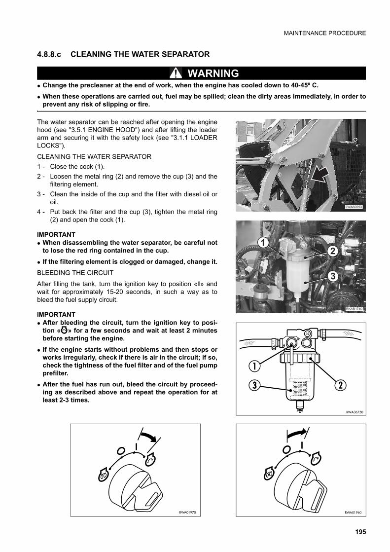
MAINTENANCE PROCEDURE
4.8.8.c CLEANING THE WATER SEPARATOR
WARNINGq Change the precleaner at the end of work, when the engine has cooled down to 40-45º C.q When these operations are carried out, fuel may be spilled; clean the dirty areas immediately, in order to
prevent any risk of slipping or fire.
The water separator can be reached after opening the enginehood (see "3.5.1 ENGINE HOOD") and after lifting the loaderarm and securing it with the safety lock (see "3.1.1 LOADERLOCKS").
CLEANING THE WATER SEPARATOR1 - Close the cock (1).2 - Loosen the metal ring (2) and remove the cup (3) and the
filtering element.3 - Clean the inside of the cup and the filter with diesel oil or
oil.4 - Put back the filter and the cup (3), tighten the metal ring
(2) and open the cock (1).
IMPORTANTq When disassembling the water separator, be careful not
to lose the red ring contained in the cup.q If the filtering element is clogged or damaged, change it.BLEEDING THE CIRCUIT
After filling the tank, turn the ignition key to position « » andwait for approximately 15-20 seconds, in such a way as tobleed the fuel supply circuit.
IMPORTANTq After bleeding the circuit, turn the ignition key to posi-
tion « » for a few seconds and wait at least 2 minutesbefore starting the engine.
q If the engine starts without problems and then stops orworks irregularly, check if there is air in the circuit; if so,check the tightness of the fuel filter and of the fuel pumpprefilter.
q After the fuel has run out, bleed the circuit by proceed-ing as described above and repeat the operation for atleast 2-3 times.
��������
RWA01970
��������
�
�
�
RWA01960
RWA36750
1
23
195

MAINTENANCE PROCEDURE
4.8.8.d DRAINING THE HYDRAULIC OIL TANK (Only for machines filled with synthetic biodegradable oil type HEES)
WARNINGq Lower the loader arm completely, rest the bucket on to
the ground and, after stopping the engine, eliminate theresidual pressures that may be present in the equip-ment (by operating the controls more than once) andlock the safety bars (see "3.3.5 pos. 1 - SAFETYBARS").
q Let the oil cool down until it reaches 40-45ºC before per-forming any maintenance operation.
q Immediately clean any area dirty with oil.
Stop the machine on a firm and level surface, lower the equip-ment to the ground, stop the engine and release the residualpressures that may be present in the equipment by operatingthe controls more than once.Raise the engine hood (see "3.5.1 ENGINE HOOD") and openthe rear panel (see "3.5.2 REAR PANEL").1 - Slowly loosen the filling cap (1) to release the residual
pressure from the tank and remove it.2 - Loosen the lower plug (2) until the condensate has flown
out of the tank completely.Use a 12 mm hexagon spanner.
3 - Put back the lower plug (2), the filling cap (1) and closethe rear panel and the engine hood.
IMPORTANTq The draining of the tank must be carried out at tempera-
tures exceeding 0ºC, before starting the engine; whenthe temperature is below 0ºC, the hydraulic oil tank mustbe drained at the end of work, or in any case when thetemperature of the machine is sufficiently high to pre-vent the condensate from freezing and to allow it to flowout of the tank without problems.
RWA37070
������ ��
�
������ ��
���������RWA34230
2
196

MAINTENANCE PROCEDURE
4.8.9 MAINTENANCE EVERY 1000 HOURS OF OPERATION These operations must be carried out together with those to be carried out EVERY 50, 250, 500 HOURS.
4.8.9.a CHANGING THE OIL IN THE FINAL TRANSMISSION
WARNINGq Oils, filters, coolants and batteries are considered spe-
cial waste and must be collected and disposed of ac-cording to the anti-pollution regulations in force.
This operation must be carried out on each transmission withthe machine parked on level ground and at operating tempera-ture, so that the oil becomes fluid and can be drained easily to-gether with the solid particles suspended in it.Before changing the oil, lift the loader arm and secure it withthe safety lock (see "3.1.1 LOADER LOCKS")1 - Remove the drain plug (1) and let the used oil flow out
completely. Use a 19 mm hexagon spanner.While the oil flows out, remove the plug (2). Use a 19 mmhexagon spanner.
2 - After draining the used oil, put back the plug (1) and fillwith the recommended oil through the hole (2) until the oilreaches the lower edge of the hole.
3 - Put back the plug (2).
Carry out some movements and check the level again with themachine at rest. Use only the recommended type of oil (see"4.3 FUEL, COOLANT AND LUBRICANTS").
���������
��������
���������
�
������� �
�
197

MAINTENANCE PROCEDURE
4.8.9.b CHANGING THE HYDRAULIC SYSTEM OIL AND CLEANING THE SUCTION FIL-TER
CAUTIONq On machines filled with synthetic biodegradable hy-
draulic oil type HEES the oil must be changed after thefirst 500 hours of operation and successively every 1000hours, and in any case at least once a year.
WARNINGq Lower the loader arm completely, lower the bucket to
the ground, stop the engine, release the residual pres-sures from the work equipment circuits (by operatingthe controls more than once) and lock the safety bars(see "3.3.5 pos. 1 - SAFETY BARS").
q Let the oil cool down until it reaches 40-45ºC before car-rying out any maintenance operation.
q Immediately clean any area dirty with oil.q Oils, filters, coolants and batteries are considered spe-
cial waste and must be collected and disposed of ac-cording to the anti-pollution regulations in force.
Stop the machine on a firm and level surface, lower the equip-ment to the ground, stop the engine and release the residualpressures from the work equipment circuits by operating thecontrols more than once. Raise the engine hood (see "3.5.1 ENGINE HOOD") and openthe rear panel (see "3.5.2 REAR PANEL").1 - Slowly loosen the filling cap (1) to release the residual
pressure from the tank and then remove it.2 - Remove the lower plug (2) and let the used oil flow out
completely, gathering it in a container with suitable capac-ity. Use a 12 mm hexagon spanner.
RWA37070
������ ��
�
������ ��
���������RWA34230
2
198

MAINTENANCE PROCEDURE
3 - Once the oil has been drained, disconnect the suctionpipe (3) and remove the flange (4) after removing thescrews (5). Use a 17 mm hexagon spanner.
4 - Clean the filtering element (6).5 - Put back the flange (4), the filter (6), the gasket (7) and
the lower plug (2).6 - Fill the tank with the prescribed oil until reaching the level
(8). Use only the prescribed type of oil (see "4.3 FUEL,COOLANT AND LUBRICANTS").
7 - Raise the cab (see "3.5.3.1 RAISING THE CAB") surethat the oil in the hydraulic pump reaches the maximumlevel. To do this, remove the upper plug (9 and make surethat the hole is completely filled with oil. Use a 1/2” squaresection spanner.
8 - If the oil does not reach the maximum level, top up withthe prescribed oil (see "4.3 FUEL, COOLANT AND LU-BRICANTS").
9 - After the check, lower the cab, screw the filling cap (1),close the rear panel and the engine hood and deaeratethe system.
10 - Make sure that all the control levers are in neutral positionand let the engine idle for 2-3 minutes before operatingthe work equipment.Move each piston more than once to deaerate the sy-stem; check again and top up if necessary.
CAUTIONq Never start the engine with empty tank, since this would
certainly damage the pump.
4.8.9.c CHECKING AND ADJUSTING THE ENGINE VALVE CLEARANCESince the check and adjustment of the engine valve clearance require the use of special tools, have these opera-tions carried out by your Komatsu Dealer.
RWA364005
74 63
���������
��������
�
��������
199
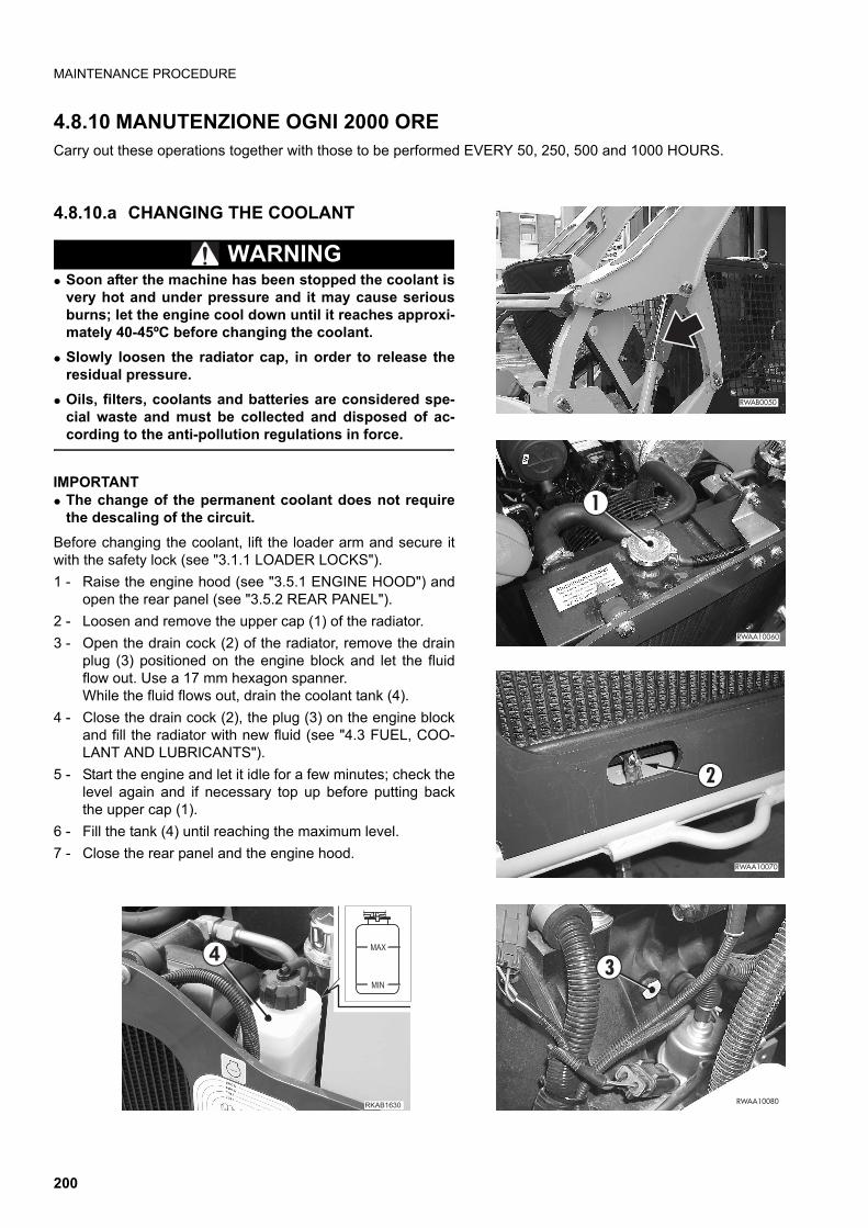
MAINTENANCE PROCEDURE
4.8.10 MANUTENZIONE OGNI 2000 ORE Carry out these operations together with those to be performed EVERY 50, 250, 500 and 1000 HOURS.
4.8.10.a CHANGING THE COOLANT
WARNINGq Soon after the machine has been stopped the coolant is
very hot and under pressure and it may cause seriousburns; let the engine cool down until it reaches approxi-mately 40-45ºC before changing the coolant.
q Slowly loosen the radiator cap, in order to release theresidual pressure.
q Oils, filters, coolants and batteries are considered spe-cial waste and must be collected and disposed of ac-cording to the anti-pollution regulations in force.
IMPORTANTq The change of the permanent coolant does not require
the descaling of the circuit.Before changing the coolant, lift the loader arm and secure itwith the safety lock (see "3.1.1 LOADER LOCKS").1 - Raise the engine hood (see "3.5.1 ENGINE HOOD") and
open the rear panel (see "3.5.2 REAR PANEL").2 - Loosen and remove the upper cap (1) of the radiator.3 - Open the drain cock (2) of the radiator, remove the drain
plug (3) positioned on the engine block and let the fluidflow out. Use a 17 mm hexagon spanner.While the fluid flows out, drain the coolant tank (4).
4 - Close the drain cock (2), the plug (3) on the engine blockand fill the radiator with new fluid (see "4.3 FUEL, COO-LANT AND LUBRICANTS").
5 - Start the engine and let it idle for a few minutes; check thelevel again and if necessary top up before putting backthe upper cap (1).
6 - Fill the tank (4) until reaching the maximum level.7 - Close the rear panel and the engine hood.
��������
���������
�
��������
�
�
�������������� �
� ���
���
200

MAINTENANCE PROCEDURE
4.8.10.b CHANGING THE SUCTION FILTER
WARNINGq Lower the loader arm completely, rest the bucket on to
the ground, stop the engine, eliminate the residual pres-sures that may be present in the equipment (by operat-ing the controls more than once) and lock the safetybars (see "3.3.5 pos. 1 - SAFETY BARS").
q Before carrying out any maintenance operation, let theoil cool down until it reaches 40-45º C.
q Immediately clean any area dirty with oil.q Oils, filters, coolants and batteries are considered spe-
cial waste and must be collected and disposed of ac-cording to the anti-pollution regulations in force.
Stop the machine on a firm and level surface, lower the equip-ment to the ground, stop the engine and release the residualpressures from the equipment by operating the controls morethan once.Raise the engine hood (see "3.5.1 ENGINE HOOD") and openthe rear panel (see "3.5.2 REAR PANEL").
The suction filter must be changed every two hydraulic oilchanges.1 - Slowly loosen the filling cap (1) in order to release the re-
sidual pressure from the tank and then remove it.
RWA37070
������ ��
�
������ ��
���������
201

MAINTENANCE PROCEDURE
2 - Drain the hydraulic oil (see "4.8.9.b CHANGING THEHYDRAULIC SYSTEM OIL AND CLEANING THE SUC-TION FILTER").
3 - Once the oil has been drained, disconnect the suctionpipe (3) and remove the flange (4) after removing thescrews (5). Use a 17 mm hexagon spanner.
4 - Change the filtering element (6).5 - Put back the flange (4), the filter (6), the gasket (7) and
the lower plug (2).6 - Complete the tank filling operations by proceeding as de-
scribed in paragraph "4.8.9.b CHANGING THE HYDRAU-LIC SYSTEM OIL AND CLEANING THE SUCTIONFILTER".
CAUTIONq Never start the engine with empty tank, since this would
certainly damage the pump.
4.8.10.c CHECKING THE ALTERNATOR AND THE STARTERFor any inspection and/or repair, contact your Komatsu Dealer.If the engine is started frequently, the alternator and the starter should be inspected every 1000 hours of operation.
RWA34230
2
RWA364005
74 63
202

�������������������
203

TECHNICAL DATA
5.1 TECHNICAL DATA
5.1.1 STANDARD MACHINE OVERALL DIMENSIONSIMPORTANTq The weight of the machine increases by 200 kg when it is equipped with solid tyres.q If the bucket is provided with teeth, the machine length increases by 100 mm.q With extended bucket the machine length increases by 130 mm.
OVERALL DIMENSIONS WITH STANDARD BUCKET L 1730 AND TYRES (10x16.5)
RWA36820
107020
7022
50
106012903420
180
1730
16701380
210
204

TECHNICAL DATA
OVERALL DIMENSIONS WITH BUCKET L 1550 AND TYRES (10x16.5)
OVERALL DIMENSIONS WITH BUCKET L 1800 AND TYRES (10x16.5)
RWA36810
1070
2070
2250
106012903420
180
1550
1380
210
RWA36830
1070
2070
2250
106012903420
180
1800
16701380
210
205

TECHNICAL DATA
5.1.2 MACHINE OVERALL DIMENSIONS WITH OPTIONAL EQUIPMENTIMPORTANTq The weight of the machine increases by 200 kg when it is equipped with solid tyres.
MACHINE OVERALL DIMENSIONS WITH EXCAVATOR (E30)
MACHINE OVERALL DIMENSIONS WITH ASPHALT CUTTER
RWA36840
1070
2250
2360
2070
106021604290
1380 1640 1670
150
RWA36850
1070
2220
2420
106018303960
190
1670
15601380
206

TECHNICAL DATA
OVERALL DIMENSIONS WITH PALLET FORKS
OVERALL DIMENSIONS WITH SNOW BLADE
RWA36860
1070
2250
106016003730
180
1670
1380
RWA36870
1070
2250
106013403470
150
1700
16701380
207

TECHNICAL DATA
OVERALL DIMENSIONS WITH MIXING BUCKET
OVERALL DIMENSIONS WITH SWEEPER
RWA36880
1070
2250
106014003530
225
1670
1380
RWA36890
1070
2250
106019204050
110
1680
16701550 80501380
208

TECHNICAL DATA
OVERALL DIMENSIONS WITH GRAPPLE FORK
RWA36900
1070
2250
106013203450
180
1670
14601380
209

TECHNICAL DATA
5.1.3 TECHNICAL CHARACTERISTICS
TOTAL MASS
Standard machine max. total mass . . . . . . . . . . . . . . . . . . . . . . . . . . . . . . . . . . . . . . . . . . . . . . . . kg 2820Max. total mass with bucket L 1550 . . . . . . . . . . . . . . . . . . . . . . . . . . . . . . . . . . . . . . . . . . . . . . . . kg 2810Max. total mass with bucket L 1800 . . . . . . . . . . . . . . . . . . . . . . . . . . . . . . . . . . . . . . . . . . . . . . . . kg 2850Max. total mass with excavator E30. . . . . . . . . . . . . . . . . . . . . . . . . . . . . . . . . . . . . . . . . . . . . . . . kg 3300Max. total mass with asphalt cutter . . . . . . . . . . . . . . . . . . . . . . . . . . . . . . . . . . . . . . . . . . . . . . . . kg 3470
BUCKET CAPACITY
Narrow bucket L 1550 capacity (SAE) . . . . . . . . . . . . . . . . . . . . . . . . . . . . . . . . . . . . . . . . . . . . . m3 0.35Standard bucket L 1730 capacity (SAE). . . . . . . . . . . . . . . . . . . . . . . . . . . . . . . . . . . . . . . . . . . . m3 0.40Wide bucket L 1800 capacity (SAE). . . . . . . . . . . . . . . . . . . . . . . . . . . . . . . . . . . . . . . . . . . . . . . m3 0.41
ENGINE
Komatsu diesel engine model . . . . . . . . . . . . . . . . . . . . . . . . . . . . . . . . . . . . . . . . . . . . . . . . . . . . . . 4D88E-5KFDRated power (2800 rpm EEC 80/1269) . . . . . . . . . . . . . . . . . . . . . . . . . . . . . . . . . . . . . . . . . . . . .kW 33,6Maximum torque (1200 rpm EEC 80/1269) . . . . . . . . . . . . . . . . . . . . . . . . . . . . . . . . . . . . . . . . Nm 145
ELECTRICAL SYSTEM
Alternator . . . . . . . . . . . . . . . . . . . . . . . . . . . . . . . . . . . . . . . . . . . . . . . . . . . . . . . . . . . . . . . . . . . . . . 12 VElectrical output . . . . . . . . . . . . . . . . . . . . . . . . . . . . . . . . . . . . . . . . . . . . . . . . . . . . . . . . . . . . . . . . . 40 AEarthing . . . . . . . . . . . . . . . . . . . . . . . . . . . . . . . . . . . . . . . . . . . . . . . . . . . . . . . . . . . . . . . . . . . . . . . negativeBattery . . . . . . . . . . . . . . . . . . . . . . . . . . . . . . . . . . . . . . . . . . . . . . . . . . . . . . . . . . . . . . . . . . . . . . . . 80 Ah-12 VStarter . . . . . . . . . . . . . . . . . . . . . . . . . . . . . . . . . . . . . . . . . . . . . . . . . . . . . . . . . . . . . . . . . . . . . kW 2.3
SPEED
TYRES
SIZE MAKE INFLATION PRESSURE10x16.5 PR8 ECOMEGA bar 4.2
10x16.5 SKS PR8 HAULER bar 3.7510x16.5 NHS SGL PR6 GOOD-YEAR bar 3.1
FORWARD REVERSE
GEARS 1 2 1 2
km/h 10.5 16 10.5 16
210

TECHNICAL DATA
SOLID TYRES
SIZE MAKE10x16.5 AIR BOSS
211

PAGE INTENTIONALLY LEFT BLANK
212

����� ��������������������
213

AUTHORIZED OPTIONAL EQUIPMENT
6.1 AUTHORIZED OPTIONAL EQUIPMENT
CAUTIONq Komatsu machines can be supplied with optional equipment in addition to the standard equipment; if
optional equipment is installed and used, carefully read the relevant operation manual and keep to theinstructions given therein.
q Use exclusively optional or special equipment recommended and approved by Komatsu and complyingwith the requisites indicated in the table (see "6.1.4 CHARACTERISTICS OF THE OPTIONAL EQUIPMENTOF THE MACHINE VERSION WITH HIGH-FLOW AND SUPER-FLOW HYDRAULIC SYSTEM").
q Komatsu cannot be held liable for any damage, accident, reduction of the machine efficiency due to theapplication and use of unauthorized equipment.
6.1.1 PRECAUTIONS REGARDING SAFETYThe installation of optional accessories or equipment other than those authorized by Komatsu shortens the life ofthe machine and may also cause problems concerning safety.It is advisable to contact a Komatsu Dealer before installing any accessory not indicated in this operation andmaintenance manual. In case of failure to comply with this recommendation, Komatsu declines any responsibility for accidents or dama-ge.
WARNINGq When removing or installing any equipment, take the following precautions and be careful to the safety
conditionsq Carry out installation and removal on a firm and flat surface.q When the operations are carried out by two or more operators, decide the communication signals in
advance and respect them during the operations.q Use a crane to handle objects weighing more than 25 kg.q Always support any heavy part before removing it. When heavy parts are lifted, be always careful to the
position of the center of gravity of the object being handled.q It is very dangerous to carry out any operation with a suspended load; therefore, always position the
load on a support and make sure that it is in a safe position.q When installing or removing any equipment, make sure that it is stable and cannot fall down.q Never stand under loads being lifted by a crane.
Take care to choose a safe position, where you do not run any risk in case the load should fall down.
IMPORTANTq Cranes must be operated by specialized personnel. Do not allow non-specialized personnel to use
cranes.For further details regarding installation and removal operations, contact your Komatsu Dealer.
214

AUTHORIZED OPTIONAL EQUIPMENT
6.1.2 PRECAUTIONS REGARDING THE INSTALLATION OF EQUIPMENT
WARNINGq The use of lengthened work equipment reduces the stability of the machine.
If it is necessary to go up or down a slope, be particularly careful, since the machine may lose its bal-ance and overturn.
q When installing work equipment with dimensions exceeding those of the standard equipment, be carefulto the space necessary for the movements of the equipment and of the machine.
215

AUTHORIZED OPTIONAL EQUIPMENT
6.1.3 CHARACTERISTICS OF THE STANDARD MACHINE OPTIONAL EQUIPMENT
(Specific weight of the handled material = 1,8 t/m3)
q Max. outreache Max. digging deptha The value is referred to the drill diameteru Max. tooth length
EQUIPMENTMAX.
WEIGHT (kg)
MAX. DIMENSIONS MAX. SAECAPACITY
(cu m)
MAX. OPERA-TING PRESSURE
(bar)
MAX. FLOW RATE (l/min.)
Width(mm)
Height (mm)
Front bucket 200 1800 600 0.422 — —
Multi-purpose front bucket — — — — 190 62
Excavator 680 q3150 e2800 Excavator0.052 155 62
Excavator bucket 66 600 — 0.052 — —
Hydraulic hammer 150 — 950 — 190 62
Drill 170 a300 1500 — 190 62
Pallet fork 125 1400 650 u800 — —
Manure fork 95 1450 510 — — —
Grapple fork 155 1450 580 — 190 62
216

AUTHORIZED OPTIONAL EQUIPMENT
6.1.4 CHARACTERISTICS OF THE OPTIONAL EQUIPMENT OF THE MACHINE VERSION WITH HIGH-FLOW AND SUPER-FLOW HYDRAULIC SYSTEM
(Specific weight of the handled material = 1,8 t/m3)
q Max. outreache Max. digging deptha The value is referred to the drill diameteru Max. tooth lengthT Cutting depth
EQUIPMENTMAX.
WEIGHT (kg)
MAX. DIMENSIONS MAX. SAECAPACITY
(cu m)
MAX. OPERA-TING PRESSURE
(bar)
MAX. FLOW RATE (l/min.)
Width(mm)
Height (mm)
Front bucket 200 1800 600 0.422 — —
Multi-purpose front bucket — — — — 190 62
Asphalt cutter 700 450 T150 — 190 100
Excavator 680 q3150 e2800 Excavator0.052 155 62
Excavator bucket 66 600 — 0.052 — —
Hydraulic hammer 150 — 950 — 190 62
Drill 170 a300 1500 — 190 62
Pallet fork 125 1400 650 u800 — —
Manure fork 95 1450 510 — — —
Grapple fork 155 1450 580 — 190 62
217

CHANGING THE AUTHORIZED EQUIPMENT
6.2 CHANGING THE AUTHORIZED EQUIPMENT
WARNINGq Stop the machine on a firm and level surface and lower the equipment to the ground.q Before getting off the machine, stop the engine, release the residual pressures by moving the equipment
control lever more than once in all directions and lock the safety bars (see "3.3.5 pos. 1 - SAFETYBARS").
q Before starting work, make sure that the PAN-TACH coupling pins are completely engaged in the seatsprovided on the equipment and that the control lever is completely turned rightwards.
q Do not use your fingers to center the holes, since they may be injured or even cut due to sudden or un-controlled movements.
The machine is provided with a special tool-holder, called «PAN-TACH», which is used for the installation of buc-kets or optional equipment.Change the optional equipment adopting the same procedure adopted to change the bucket.See "3.13.6 CHANGING THE BUCKET OR THE EQUIPMENT WITH STANDARD RAPID COUPLING".Besides the assembly on the tool-holder, the hydraulic excavator requires also the fastening to the machine bymeans of two connection tie-rods and the hydraulic connection for the independent control of the equipment.When changing equipment with independent hydraulic circuit, interrupt the oil flow to the equipment with the auxi-liary kit pedal and disconnect the union pipes before releasing the equipment from the tool-holder.See "6.2.2 CONNECTING THE HYDRAULIC CIRCUIT".
6.2.1 CONNECTING THE EXCAVATORCouple the excavator to the PAN-TACH with the same proce-dure adopted for the standard equipment and apply the con-nection tie-rods.1 - Apply the tie-rods (1) to the excavator and secure them
with the safety pins (2).2 - Engage the tie-rods with the couplings (3) and connect
the hydraulic circuit.See "6.2.2 CONNECTING THE HYDRAULIC CIRCUIT".
To disconnect the excavator from the PAN-TACH device, pro-ceed as follows:1 - Release the tie rods (1) from the plates (3) and disconnect
the hydraulic circuit of the excavator.2 - Raise the tie rods (1) and fix them with the safety locks
(4).
���������
��
���������
�
�
218

CHANGING THE AUTHORIZED EQUIPMENT
6.2.2 CONNECTING THE HYDRAULIC CIRCUIT
WARNINGq Before performing any operation on the hydraulic circuit, stop the engine and eliminate the residual
pressures from the equipment circuits by operating the controls more than once, then lock the safetybars (see "3.3.5 pos. 1 - SAFETY BARS").
q Immediately clean any area dirty with oil.
After the mechanical connection of equipment with indepen-dent hydraulic circuit, make sure that the auxiliary kit controlpedal is in position A - flow interrupted - and introduce theflexible pipes of the equipment connection in the unions (1)and (2). See B,C and DThe rapid coupling must be in compliance with the ISO 8434-3standard.
IMPORTANTq In case of doubts regarding the connection of the hy-
draulic circuit to the equipment, contact your KomatsuDealer
RWA36090
1" UNS
1" UNS
1
2
��������
��
�
��������
�
219

CHANGING THE AUTHORIZED EQUIPMENT
������ �
�
� �
RWA36110
1"3/16 UN
1"3/16 UN
1
2
��������
�
��
RWA36090
1" UNS
1" UNS
1
2
220

CHANGING THE AUTHORIZED EQUIPMENT
6.2.3 CONNECTING THE RETURN CIR-CUIT WITH DIRECT DRAINAGE INTO THE TANK
WARNINGq Before performing any operation on the hydraulic cir-
cuit, stop the engine and eliminate the residual pres-sures from the equipment circuits by operating thecontrols more than once, then lock the safety bars (see"3.3.5 pos. 1 - SAFETY BARS").
q Immediately clean any area dirty with oil.
The machine may be fitted for the application of equipmentwith separate return circuit directed into the tank.The return system is positioned on the left side of the loaderarm and the equipment drain pipe must be connected to theunion (1).
IMPORTANTq In case of doubts regarding the connection of the hy-
draulic circuit to the equipment, contact your KomatsuDealer.
RWA36100
1" UNS 1
���������
��������
�
221

CHANGING THE AUTHORIZED EQUIPMENT
6.2.4 PREPARING THE MACHINE FOR THE USE OF THE EXCAVATOR
After the installation of the excavator, make sure that themechanical and hydraulic connections have been carried outcorrectly and proceed as follows.1 - Press the auxiliary kit control pedal with your toe until en-
gaging it in position (B); this position ensures the flow ofoil to the equipment.
2 - For the use of the excavator, see the specific instructionmanual.
3 - If the machine is equipped with rear stabilizers, lowerthem until the rear wheels are partially raised; this ma-noeuvre stabilizes the machine and avoids any tyre over-load (see "3.3.5 pos. 13 - RIGHT STABILIZER CONTROL(IF INSTALLED)" e pos. 14 - LEFT STABILIZER CON-TROL (IF INSTALLED)").
6.2.5 USING THE MACHINE WITH THE EXCAVATOR
WARNINGq Before using the excavator, read the relevant operation and maintenance manual carefully and keep to
the instructions contained therein.q If the machine is equipped with rear stabilizers, always lower them before using the excavator.q After the digging operation and before moving the machine, bring the stabilizers back to their original
position.q If it is necessary to travel on roads, engage all the safety locks provided. See "3.1 SAFETY LOCKS".
���������
�
222

PALLET FORKS
6.3 PALLET FORKS
CAUTIONq Before using the forks for any operation, the operator must get acquainted with the increased dimen-
sions of the machine and must also practise the use of the swinging movements.q After grasping the material with the forks and before lifting the load, swing the equipment in such a way
as to lift the points and prevent the load from slipping.q Use the lifting, swing and travel controls slowly and smoothly, in order to avoid jerks that may cause the
load to move.q Use the maximum fork width possible.q The forks must always be resting on the plate and be secured in their position by means of the safety
pins.
The pallet forks make it possible to use the machine like a normal lift truck and the controls for lifting and swingingthe loads are the same used to control the standard bucket.See "3.3.5 MACHINE CONTROLS".The pallet forks may have different width (distance from each other) according to the load to be handled: it is suffi-cient to make them slide on the upper coupling bar; once the desired position has been found, carry out slight mo-vements to make sure that the upper lock pin is engaged in its seat.
223

CHANGING THE OPERATING PATTERN
6.4 CHANGING THE OPERATING PATTERN
WARNINGq Before changing the setting of the pattern change valve to modify the operating pattern of the machine,
lower the equipment to the ground, stop the engine and lock the controls by lifting the safety bars in ver-tical position (see "3.3.5 pos. 1 - SAFETY BARS")
q After changing the control operating pattern, carry out the first manoeuvres slowly and very carefully, inorder to understand the new controls correctly and avoid any damage or fatal injury that may be causedby incorrect movements.
q After changing the control operating pattern and before checking the movements of the machine, makesure that the area is clear of obstacles and that no one is standing in the range of movement of the ma-chine.
The pattern change valve (1) is positioned inside the enginehood, on the cab's rear wall, and it can be reached after open-ing the engine hood ( "3.5.1 ENGINE HOOD").
RWA37070
����� ��
�
224

CHANGING THE OPERATING PATTERN
The lever (2) controlling the pattern change valve has two po-sitions:A - Position for the ISO PATTERN CONTROL SYSTEM
B - Position for the OPTION PATTERN CONTROL SYSTEM
����� ��
� �
RKA10390
ISO PATTERN
N
F
N
R
��������
� �
RKA10400
OPTION PATTERN
N
F
R
N
F
R
225

CHANGING THE OPERATING PATTERN
6.4.1 HOW TO CHANGE THE OPERAT-ING PATTERN
After stopping the machine on a firm and level surface, lowerthe equipment to the ground, stop the engine and lock the con-trols by lifting the safety bars in vertical position.Open the engine hood and proceed as follows:1 - Loosen the safety screw (3) that holds the selection lever
(2) in position.Use a 13 mm hexagon wrench.
2 - Select the desired operating pattern by rotating the lever(2) to position "A" for the ISO PATTERN or to position "B"for the OPTION PATTERN.
3 - Secure the lever in the selected position with the safetyscrew (3).
IMPORTANTq Before moving the machine, the operator must make su-
re that the selected operating pattern corresponds tothe one desired.The control panels (4) positioned at the sides of the cen-tral dashboard are backlit.
q The lighting of the plates is useful for the operator toidentify the type of operating system selected. (ISO PAT-TERN or OPTION PATTERN control system).
��������
�
��������
�
��������
� �
����� ��
� �
226

HAND & FOOT CONTROL SYSTEM
6.5 HAND & FOOT CONTROL SYSTEM
6.5.1 MACHINE CONTROLS
CAUTIONq The controls represented in the figure and not described in this section remain unchanged and are the
same present on the standard version. For details on how to use them, see "3.3.5 MACHINE CON-TROLS".
1 - Left joystick control lever HAND & FOOT CONTROL SYSTEM(Left wheel travel)
2 - Right joystick control lever HAND & FOOT CONTROL SYSTEM (Right wheel travel and auxiliary hydraulic kit control)
3 - Left foot-operated servo control HAND & FOOT CONTROL SYSTEM(Loader arm lifting and lowering control)
4 - Right foot-operated servo control HAND & FOOT CONTROL SYSTEM (Bucket opening and folding control)
RKA10410
1 2
3 4
227

HAND & FOOT CONTROL SYSTEM
6.5.1.1 TRAVEL AND STEERING CONTROL LEVERS
WARNINGq Before carrying out any manoeuvre with the levers, the operator must be seated in driving position with
fastened safety belt and lowered safety bars; before any manoeuvre it is important to take all the precau-tions indicated in "6.5.2 HOW TO MOVE THE MACHINE (HAND & FOOT CONTROL SYSTEM)".
q Before moving the machine, make sure that the parking brake is released.q When travelling on roads, always inhibit the equipment control (see "3.3.5 pos. 8 - EQUIPMENT CON-
TROL LOCKING LEVER (IF INSTALLED)").q When travelling on roads, always make sure that all safety locks are engaged.q Before leaving the operator seat, stop the engine only after lowering the equipment to the ground and
locking the controls (safety bars lifted in vertical position).q Non-compliance with these rules may lead to serious accidents.
The travel control levers (1) and (2) are positioned on the Op-erator's left and right side, respectively, and they control theforward and reverse travel of the machine according to themovements shown in the diagram.
IMPORTANTq To move the machine forward or in reverse, shift the le-
vers (1) and (2) at the same time and in the same direc-tion.
q For further details on the use of the levers, see pos.6.5.2 HOW TO MOVE THE MACHINE (HAND & FOOTCONTROL SYSTEM)"
N - NeutralA - ForwardB - Reverse
�
������ �
�
�
��������
RKA10420
N
A A
B B
N
228

HAND & FOOT CONTROL SYSTEM
The lever (2) is used to control the right wheels and also to control the auxiliary hydraulic kit according to themovements indicated in the following diagram:
N - NeutralA - Right wheel forward travelB - Right wheel reverse travelC - Oil delivery from the male coupling of the auxiliary hydrau-
lic kitD - Oil delivery from the female coupling of the auxiliary hy-
draulic kit
For details on the use of the auxiliary hydraulic kit, see "6.5.1.3AUXILIARY HYDRAULIC KIT CONTROL"
CAUTIONq Always travel with the engine running at moderate speed, in order to obtain maximum precision and
maximum productivity during work.q During work, the use of the levers must be proportional to the effort required and such as to keep the en-
gine running at constant speed.q Operate the levers smoothly, without abrupt movements and avoid counter-rotations as much as possi-
ble, since this type of manoeuvre causes the untimely wear of the tyres.
NOTEq The horn (3) is positioned on the grip of the left lever (1) and must be used to warn all the people in the vicinity
before starting work and in case of danger.
q All movements can be inhibited by shifting the safety bars to the vertical locking position. (See "3.3.5 pos. 1 -SAFETY BARS").
RKA10430
N
A
B
C D
229

HAND & FOOT CONTROL SYSTEM
6.5.1.2 WORK EQUIPMENT CONTROL PEDALS (LOADER ARM AND BUCKET)
WARNINGq Before carrying out any manoeuvre with the pedals, the operator must be seated in driving position with
fastened safety belt and lowered safety bars; before any manoeuvre it is important to take all the precau-tions indicated in "3.13 USING THE WORK EQUIPMENT".
q When travelling on roads, always inhibit the equipment control (see "3.3.5 pos. 8 - EQUIPMENT CON-TROL LOCKING LEVER (IF INSTALLED)").
q Before leaving the operator seat, stop the engine only after lowering the equipment to the ground andlocking the controls (safety bars lifted in vertical position).
q Non-compliance with these rules may lead to serious accidents.
CAUTIONq The self-leveling system is operated automatically only when the loader arm is lifted with full bucket.
When the arm is being lowered, the self-leveling system doesn't start.q At the maximum height, the self-leveling system keeps the bucket partially folded to prevent the material
from being spread out.
The control pedals (1) and (2) are positioned on the footboardunder the operator seat and control the movements of theloader arm and the bucket. �
��������
�
230

HAND & FOOT CONTROL SYSTEM
The pedal (1), positioned on the operator's left, controls the lift-ing and lowering of the loader arm, as indicated in the follow-ing diagram:
N - NeutralA - Loader arm upB - Loader arm down
IMPORTANTq On machines provided with floating device, press the
pedal to position B (arm down) and press the switch po-sitioned under the right joystick (see "3.3.5 MACHINECONTROLS").
�
��������
N
N
A
ARKA10440
N
N
BB
RKA10450
231

HAND & FOOT CONTROL SYSTEM
The pedal (2), positioned on the operator's right, controls thefolding and dumping of the bucket, as indicated in the follow-ing diagram:
N - NeutralA - Bucket foldingB - Bucket dumping
�
��������
N
N
A
ARKA10460
N
N
BB
RKA10470
232

HAND & FOOT CONTROL SYSTEM
6.5.1.3 AUXILIARY HYDRAULIC KIT CONTROL
WARNINGq Before carrying out any manoeuvre with the control lever, the Operator must be seated in driving posi-
tion with fastened safety belt and lowered safety bars.
The control lever (1) is positioned on the operator's right andcontrols the movement of the right wheels and the auxiliary hy-draulic kit, according to the movements indicated on the plate(2) and in the following diagram:
N - NeutralA - Right wheel forward travelB - Right wheel reverse travelC - Oil delivery from the male coupling (3) of the auxiliary hy-
draulic kitD - Oil delivery from the female coupling (4) of the auxiliary
hydraulic kit
�
��������
�
�������
RKA10430
N
A
B
C D
233

HAND & FOOT CONTROL SYSTEM
The auxiliary hydraulic kit control starts and stops the oil flow to any optional equipment and has four positions(neutral, left, right and coupling position).
1 - Neutral position (N)(CLOSED HYDRAULIC CIRCUIT)This position doesn't allow the optional equipment to beused.
2 - Positions (C ) and (D)(OPEN HYDRAULIC CIRCUIT).These positions are used to control optional equipmentwith bidirectional oil flow (multi-purpose bucket, drill, as-phalt cutter, etc.). Rotate the lever (1) to position (C) to de-liver oil from the male coupling (3) positioned on the leftside of the loader arm, or to position (D) to deliver oil fromthe female coupling (4).
RKA10480
NC
D
E1
�������
�
�
NC
D1
RKA10490
234

HAND & FOOT CONTROL SYSTEM
3 - Coupling position (E)(OPEN HYDRAULIC CIRCUIT). This position is used to obtain a continuous unidirectionaloil flow for the operation of equipment such as excavator,demolition hammer, sweeper, etc. To hold the lever (1) incoupling position (E), rotate the lever further to the left.
NOTEq The lever (1) remains in coupling position (E) only with pres-
surised hydraulic system.When the lever (1) is in position (E), pressurised oil is deliv-ered from the male coupling (3), with return to the femalecoupling (4).
�������
�
�
�
�
RKA10500
NC
E1
235

HAND & FOOT CONTROL SYSTEM
6.5.2 HOW TO MOVE THE MACHINE (HAND & FOOT CONTROL SYSTEM)
WARNINGq Before moving the machine, make sure that you know the control functions and all the relevant safety
regulations perfectly.q The operator must be seated in driving position with fastened safety belt and lowered safety bars.q Before moving the machine, check the position of the rear-view mirrors (if installed) and make sure that
there is no one within the operating radius of the machine and that there are no obstacles in the sur-rounding area.
q Be extremely careful when engaging the reverse and make sure that there are no persons, other equip-ment or obstacles in the way.
q Avoid any travel manoeuvre or change of direction with the accelerator at maximum speed, since ma-noeuvres carried out in these conditions may cause dangerous movements.
q Do not use the speed increase function when changing direction or carrying out a counter-rotation.The speed increase function must be used only for travelling at high speed
Before moving the machine, after checking the instruments and heating the engine and the hydraulic system oil,make sure that the control safety device is released (safety bars lowered) and that the bucket is folded; the equip-ment control pedals must be in neutral position. At this point, release the parking brake.
1 - Pull the manual accelerator lever and run the engine atidle speed.
RKA10510
236

HAND & FOOT CONTROL SYSTEM
2 - Shift the joysticks (1) and (2) forwards or backwards at thesame time to move the machine.
������� �
��
RWA32270
N N
237

HAND & FOOT CONTROL SYSTEM
6.5.2.1 STEERING (CHANGING DIRECTION)
WARNINGq Avoid abrupt changes of direction as much as possible. Carry out counter-rotations at moderate speed.q Avoid carrying out counter-rotations when travelling on roads, since these manoeuvres may cause dangerous
situations; make counter-rotations only during work.q Do not use the speed increase function when changing direction or carrying out a counter-rotation.
CHANGING DIRECTION WITH MACHINE AT RESTTo turn to the LEFT, use the right joystick as follows: to moveFORWARD, push the joystick. To move BACKWARD, pull thejoystick.
To turn to the RIGHT, use the left joystick as follows : to modeFORWARD, push the joystick. To move BACKWARD, pull thejoystick.
RWA32280
N N
RWA32290
N N
238

HAND & FOOT CONTROL SYSTEM
CHANGING DIRECTION WITH MACHINE IN MOVEMENT(THE TWO JOYSTICKS ARE SHIFTED TO THE SAME PO-SITION)To turn to the LEFT, shift the left joystick to the NEUTRAL posi-tion (N) and the machine will turn to the LEFT.
To turn to the RIGHT, shift the right joystick to the NEUTRALposition (N) and the machine will turn to the RIGHT.
HOW TO PERFORM A COUNTER-ROTATION (with machine at rest) To perform a counter-rotation to the LEFT, pull the left joystickbackward and push the right joystick forward.
To perform a counter-rotation to the RIGHT, pull the right joy-stick backward and push the left joystick forward.
RWA32300
N N
RWA32310
N N
RWA32320
N N
RWA32330
N N
239

PAGE INTENTIONALLY LEFT BLANK
240


�������������� � �������������������������������������������� �!��