Size optimization of shoulder filleted shafts with relief grooves for ... · de concentración de...
7
INGENIERÍA E INVESTIGACIÓN VOL. 37 N.° 3, DECEMBER - 2017 (85-91) 85 Size optimization of shoulder filleted shafts with relief grooves for improving their fatigue life Optimización de tamaño de flechas escalonadas con ranuras de alivio para mejorar su vida a la fatiga Juan M. González-Mendoza 1 , Samuel Alcántara-Montes 2 , José de Jesús Silva-Lomelí 3 , Carlos de la Cruz-Alejo 4 , and Arturo Ocampo-Ramírez 5 ABSTRACT Although in scientific literature there are studies regarding the inclusion of relief grooves in order to diminish the amount of stress concentration in stepped shafts, the incorporation of optimization algorithms capable of parametrically determining their geometry remains unexplored. In this paper, an approach to the problem of size optimization of shoulder filleted shafts with relief grooves and subject to axial loads is presented. The objective of the optimization is to minimize the maximum value of stress at both, the root of the shoulder fillet, and the root of the groove, thus minimizing stress concentration and improving fatigue life of such elements. Under this methodology, different percentages of reduction of stress are achieved for the shafts with relief grooves, in comparison with the shafts without relief grooves. The novelty of this approach lies in the incorporation of an algorithm for the determination of the optimum geometry of the grooves. Keywords: Size optimization, stress concentration, relief groove RESUMEN Aun cuando en la literatura científica se puede hallar artículos sobre la inclusión de ranuras de alivio para disminuir el nivel de concentración de esfuerzo en flechas escalonadas, la incorporación de algoritmos de optimización capaces de determinar su geometría de manera paramétrica permanece sin explorarse. En este artículo se presenta un enfoque al problema de optimización de tamaño de flechas escalonadas con ranuras de alivio, sujetas a cargas axiales. El objetivo de la optimización es minimizar el valor máximo del esfuerzo, tanto en la raíz del escalón como en la raíz de la ranura, disminuyendo la concentración de esfuerzo y mejorando la vida a la fatiga de tales elementos mecánicos. Bajo esta metodología, se alcanzan diversos porcentajes de reducción del esfuerzo al comparar las flechas ranuradas con las flechas no ranuradas. El enfoque aporta la incorporación de un algoritmo para la determinación de la geometría óptima de las ranuras de alivio. Palabras clave: Optimización de tamaño, concentración de esfuerzo, ranura de alivio Received: June 9th 2016 Accepted: July 31st 2017 DOI: http://dx.doi.org/10.15446/ ing.investig.v37n3.57957 1 Ph.D. in Mechanical Engineering, S.E.P.I. Zacatenco, I.P.N., Mexico. Affiliation: S.E.P.I. Zacatenco, I.P.N., Mexico. E-mail: [email protected] 2 Ph.D. in Physics, Université Libre de Bruxelles, Belgium. Affiliation: S.E.P.I. Zacatenco, I.P.N., Mexico. E-mail: [email protected] 3 Ph.D. in Mechanical Engineering, S.E.P.I. Zacatenco, I.P.N., Mexico. Affilia- tion: U.P.I.I.T.A., I.P.N., Mexico. E-mail: [email protected] 4 M.Sc. in Mechanical Engineering, S.E.P.I. Zacatenco, I.P.N., Mexico. Affilia- tion: S.E.P.I. Zacatenco, I.P.N., Mexico. E-mail: [email protected] 5 Ph.D. in Mechanical Engineering, S.E.P.I. Zacatenco, I.P.N., Mexico. Affilia- tion: S.E.P.I. Zacatenco, I.P.N., Mexico. E-mail: [email protected] How to cite: González-Mendoza, J.M., Alcántara-Montes, S., Silva-Lomelí, J.J., De La Cruz-Alejo, C., Ocampo-Ramírez, A., (2017). Size Optimization of shoulder filleted shafts with relief grooves for improving their fatigue lives. Ingeniería e Investigación, 37(3), 85-91. DOI: 10.15446/ing.investig.v37n3.57957 Attribution 4.0 International (CC BY 4.0) Share - Adapt Introduction Most machine parts have varying cross sections, and shafts often include steps or shoulders to accommodate bearings, gears, and other mechanical elements. These changes in cross – sectional geometry cause local stress concentration and, while it is not practical to eliminate such features, it is necessary to minimize their effects, given that the degree of stress concentration is a factor in the evaluation of fatigue strength and fatigue life. Authors like Norton (2006) and Stephens et al. (1980) suggest the use of design modifications such as relief grooves to qualitatively reduce the stress concentration in stepped shafts, without giving quantitative details on the geometry of such grooves. Other authors have studied their effects with and without optimization algorithms, on mechanical structures as vessels or bars. Shin et al. (2014) pointed out the effectiveness of relief grooves as a mean to reduce stress concentration on notched shafts, while they also mentioned that the detailed geometry of such grooves is still subject to discussion.
Transcript of Size optimization of shoulder filleted shafts with relief grooves for ... · de concentración de...

IngenIería e InvestIgacIón vol. 37 n.° 3, december - 2017 (85-91)
85
Size optimization of shoulder filleted shafts with relief grooves for improving their fatigue life
Optimización de tamaño de flechas escalonadas con ranuras de alivio para mejorar su vida a la fatiga
Juan M. González-Mendoza1, Samuel Alcántara-Montes2, José de Jesús Silva-Lomelí3, Carlos de la Cruz-Alejo4, and Arturo Ocampo-Ramírez5
ABSTRACT
Although in scientific literature there are studies regarding the inclusion of relief grooves in order to diminish the amount of stress concentration in stepped shafts, the incorporation of optimization algorithms capable of parametrically determining their geometry remains unexplored. In this paper, an approach to the problem of size optimization of shoulder filleted shafts with relief grooves and subject to axial loads is presented. The objective of the optimization is to minimize the maximum value of stress at both, the root of the shoulder fillet, and the root of the groove, thus minimizing stress concentration and improving fatigue life of such elements. Under this methodology, different percentages of reduction of stress are achieved for the shafts with relief grooves, in comparison with the shafts without relief grooves. The novelty of this approach lies in the incorporation of an algorithm for the determination of the optimum geometry of the grooves.
Keywords: Size optimization, stress concentration, relief groove
RESUMEN
Aun cuando en la literatura científica se puede hallar artículos sobre la inclusión de ranuras de alivio para disminuir el nivel de concentración de esfuerzo en flechas escalonadas, la incorporación de algoritmos de optimización capaces de determinar su geometría de manera paramétrica permanece sin explorarse. En este artículo se presenta un enfoque al problema de optimización de tamaño de flechas escalonadas con ranuras de alivio, sujetas a cargas axiales. El objetivo de la optimización es minimizar el valor máximo del esfuerzo, tanto en la raíz del escalón como en la raíz de la ranura, disminuyendo la concentración de esfuerzo y mejorando la vida a la fatiga de tales elementos mecánicos. Bajo esta metodología, se alcanzan diversos porcentajes de reducción del esfuerzo al comparar las flechas ranuradas con las flechas no ranuradas. El enfoque aporta la incorporación de un algoritmo para la determinación de la geometría óptima de las ranuras de alivio.
Palabras clave: Optimización de tamaño, concentración de esfuerzo, ranura de alivio
Received: June 9th 2016Accepted: July 31st 2017
DOI: http://dx.doi.org/10.15446/ ing.investig.v37n3.57957
1 Ph.D. in Mechanical Engineering, S.E.P.I. Zacatenco, I.P.N., Mexico. Affiliation: S.E.P.I. Zacatenco, I.P.N., Mexico. E-mail: [email protected]
2 Ph.D. in Physics, Université Libre de Bruxelles, Belgium. Affiliation: S.E.P.I. Zacatenco, I.P.N., Mexico. E-mail: [email protected]
3 Ph.D. in Mechanical Engineering, S.E.P.I. Zacatenco, I.P.N., Mexico. Affilia-tion: U.P.I.I.T.A., I.P.N., Mexico. E-mail: [email protected]
4 M.Sc. in Mechanical Engineering, S.E.P.I. Zacatenco, I.P.N., Mexico. Affilia-tion: S.E.P.I. Zacatenco, I.P.N., Mexico. E-mail: [email protected]
5 Ph.D. in Mechanical Engineering, S.E.P.I. Zacatenco, I.P.N., Mexico. Affilia-tion: S.E.P.I. Zacatenco, I.P.N., Mexico. E-mail: [email protected]
How to cite: González-Mendoza, J.M., Alcántara-Montes, S., Silva-Lomelí, J.J., De La Cruz-Alejo, C., Ocampo-Ramírez, A., (2017). Size Optimization of shoulder filleted shafts with relief grooves for improving their fatigue lives. Ingeniería e Investigación, 37(3), 85-91.DOI: 10.15446/ing.investig.v37n3.57957
Attribution 4.0 International (CC BY 4.0) Share - Adapt
Introduction
Most machine parts have varying cross sections, and shafts often include steps or shoulders to accommodate bearings, gears, and other mechanical elements. These changes in cross – sectional geometry cause local stress concentration and, while it is not practical to eliminate such features, it is necessary to minimize their effects, given that the degree of stress concentration is a factor in the evaluation of fatigue strength and fatigue life.
Authors like Norton (2006) and Stephens et al. (1980) suggest the use of design modifications such as relief grooves to qualitatively reduce the stress concentration in stepped shafts, without giving quantitative details on the geometry of such grooves. Other authors have studied their effects with and without optimization algorithms, on mechanical structures as vessels or bars.
Shin et al. (2014) pointed out the effectiveness of relief grooves as a mean to reduce stress concentration on
notched shafts, while they also mentioned that the detailed geometry of such grooves is still subject to discussion.

SIZE OPTIMIZATION OF SHOULDER FILLETED SHAFTS WITH RELIEF GROOVES FOR IMPROVING THEIR FATIGUE LIFE
INGENIERÍA E INVESTIGACIÓN VOL. 37 N.° 3, DECEMBER - 2017 (85-91)86
They used fi nite element analysis to evaluate the stress distribution in the vicinity of a notch that caused a high stress concentration on an axle shaft, and compared this distribution with that of a shaft where two relief grooves were modeled at both sides of the notch, fi nding an increase of the fatigue life due to their application. In a similar manner, Robles et al. (2013) proved the benefi cial effect of relief grooves on stepped shafts using fi nite element analysis.
Otsuka et al. (2012) introduced relief grooves in the contact area of lever and lever guide of a sealing mechanism for ultra-high pressure processing equipment, achieving a decrease of stress levels at the zone of stress concentration.
Koh et al. (1997) used stress constraints in the parametric optimization of the size and number of the external grooves of a thick walled vessel under pulsating pressure, in order to minimize the stress concentration at the grooves, thus increasing the fatigue life of the vessel.
Ghelichi et al. (2011) optimized the shape of the notch geometry of components subject to multiaxial cyclic loads, using the Liu – Zenner criterion, decreasing the stress concentration at the notch. Sonmez (2009) used optimization to fi nd the best shape for fi llets in stepped bars, in order to minimize the value of the maximum equivalent stress, when such elements are subject to axial, bending, torsional, or combined loads.
Although studies can be found regarding shape optimization of fi llets, size optimization of grooves at vessels, as well as studies on the effect of relief grooves in the vicinity of notches, the study of the optimum geometry of relief grooves in fi lleted shafts using optimization algorithms is still lacking.
Thus, the main problem to be addressed in this paper is to present an approach to the size optimization of shoulder fi lleted shafts, including relief grooves as a mean to reduce the stress concentration, while the shafts under consideration are subject to axial loads.
Description of geometry and stresses
The objective of the optimization is to minimize the maximum stress at two points, i.e., the root of the shoulder fi llet and the root of the groove on a stepped shaft subjected to an axial load, and in which, a relief groove has been introduced. A comparison of stresses and fatigue lives on the shaft before and after the application of such design modifi cation is made.
Thus, it is required to describe the geometry of the shafts, as well as loads being applied and expected stresses.
Consider a shoulder fi lleted shaft, with maximum diameter do , minimum diameter di , radius of fi llet r, subject to an axial
load as in Figure 1. The load causes an axial stress, σ22, to develop in the shaft. The abrupt change in geometry creates a stress concentration, and the maximum value of stress,σ22 max , is expected to occur at the root of the shoulder fi llet.
Figure 1. Scheme of shaft without relief groove. Source: Authors
A model of this stepped shaft without relief groove is created using a student version of the ANSYS Parametric Design Language (APDL), Ansys, Inc., (2016), so that stresses at the aforementioned point can be found for various loading cases, i.e., various values of the ratio do/di . A comparison is performed between the FEM – based value of the stress concentration factor and its theoretical value given after Equation (1) to (5), according to Pilkey (1997) for validation purposes.
Kt = C1+C2 2t / do( )+C3 2t / do( )2+C4 2t / do( )3 (1)
C1=1,200+0,860 t / r( )1/2−0,022 t / r( ) (2)
C2=−1,805−0,346 t / r( )1/2−0,038 t / r( ) (3)
C3= 2,198−0,486 t / r( )1/2+0,165 t / r( ) (4)
C4=−0,593−0,028 t / r( )1/2−0,106 t / r( ) (5)
Next, another model of the stepped shaft is created using the APDL, this time including a relief groove, as shown in Figure 2. The radius of the groove and its position with respect to a specifi ed minimum distance from the shoulder, are identifi ed as u1 , u2 , respectively. The introduction of this feature is expected to diminish the stress at the root of the fi llet, and to improve fatigue life, with optimum values of the geometry.
Figure 2. Scheme of shaft with relief groove.Source: Authors
INGENIERÍA E INVESTIGACIÓN VOL. 37 N.° 3, DECEMBER - 2017 (85-91) 87
GONZÁLEZ, ALCÁNTARA, SILVA, DE LA CRUZ AND OCAMPO
Formulation of the optimization problem
The size optimization problem can be expressed as fi nding the set of design variables {u} that minimize the objective function, i. e., the maximum axial stress at both, the root of the shoulder fi llet and the root of the relief groove, Equations (6), (7), (8), while subjected to the constraints given by Equation (9), Pérez López (2002).
minumaxi
Fi u( ){ } (6)
F1u( )= σ22 (at root of the fi llet) (7)
F2u( )= σ22 (at root of the groove) (8)
lb≤ u≤ ub (upper, lower bounds) (9)
The optimization problem is solved using an in – house tool, developed in MATLAB®, applying the available optimization function fminimax, which minimizes the largest value of a set of multivariable functions, also known as the minimax problem, through the Sequential Quadratic Programming (SQP) algorithm.
Stress values to be minimized are not explicit functions of the design variables, u1 , u2 ; instead, stresses are parametrically calculated by the models built using the ANSYS Parametric Design Language, and their values are retrieved and updated by the optimization function. A proper interface between MATLAB® and ANSYS is established, following a procedure set in Gauchía et al. (2014).
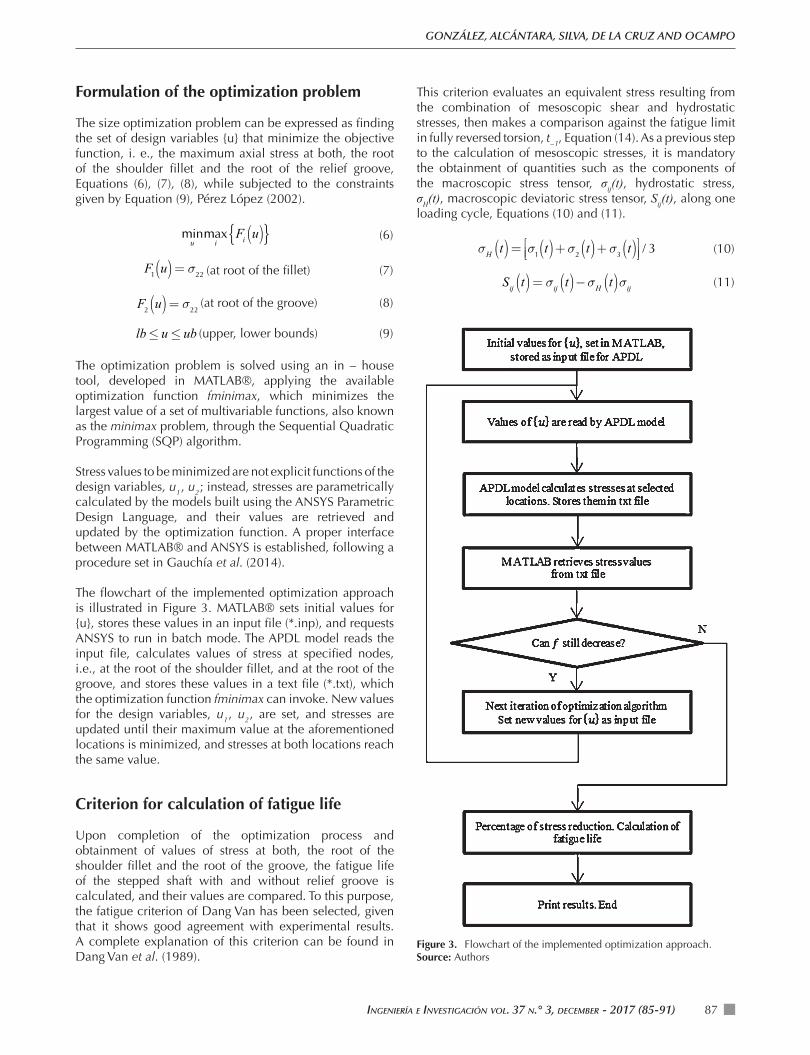
The fl owchart of the implemented optimization approach is illustrated in Figure 3. MATLAB® sets initial values for {u}, stores these values in an input fi le (*.inp), and requests ANSYS to run in batch mode. The APDL model reads the input fi le, calculates values of stress at specifi ed nodes, i.e., at the root of the shoulder fi llet, and at the root of the groove, and stores these values in a text fi le (*.txt), which the optimization function fminimax can invoke. New values for the design variables, u1 , u2 , are set, and stresses are updated until their maximum value at the aforementioned locations is minimized, and stresses at both locations reach the same value.
Criterion for calculation of fatigue life
Upon completion of the optimization process and obtainment of values of stress at both, the root of the shoulder fi llet and the root of the groove, the fatigue life of the stepped shaft with and without relief groove is calculated, and their values are compared. To this purpose, the fatigue criterion of Dang Van has been selected, given that it shows good agreement with experimental results. A complete explanation of this criterion can be found in Dang Van et al. (1989).
This criterion evaluates an equivalent stress resulting from the combination of mesoscopic shear and hydrostatic stresses, then makes a comparison against the fatigue limit in fully reversed torsion, t−1, Equation (14). As a previous step to the calculation of mesoscopic stresses, it is mandatory the obtainment of quantities such as the components of the macroscopic stress tensor, σij(t), hydrostatic stress, σH(t), macroscopic deviatoric stress tensor, Sij(t), along one loading cycle, Equations (10) and (11).
σH t( )= σ1 t( )+σ2 t( )+σ3 t( )⎡⎣⎢
⎤⎦⎥ / 3 (10)
Sij t( )= σij t( )−σH t( )σij (11)
Figure 3. Flowchart of the implemented optimization approach.Source: Authors
SIZE OPTIMIZATION OF SHOULDER FILLETED SHAFTS WITH RELIEF GROOVES FOR IMPROVING THEIR FATIGUE LIFE
INGENIERÍA E INVESTIGACIÓN VOL. 37 N.° 3, DECEMBER - 2017 (85-91)88
The calculation of the deviatoric local residual stress tensor ! ij*
, is not a trivial task when dealing with multiaxial or non – proportional loads, although for uniaxial loads evaluation of Equations (12) and (13) simplifi es. The value of α , is as in Equation (15), β = t −1 .
sij t( )= Sij t( )+ dev !ij* (12)
τ t( )= s1t( )− s3 t( )⎡
⎣⎢⎤⎦⎥ / 2 (13)
Max τ t( )+ασH t( )⎡⎣⎢
⎤⎦⎥ ≤ β (14)
α= 3t−1 / f−1⎡⎣⎢
⎤⎦⎥ −3 / 2 (15)
An in – house tool has been developed in MATLAB®, for the calculation of fatigue life using this criterion and Basquin’s equation (16). Stress components for calculation of fatigue life are taken from the value of σmax = σ22 max, assuming a ratio R = σmin / σmax = −1.
β = τ f' 2N f( )b (16)
Numerical examples
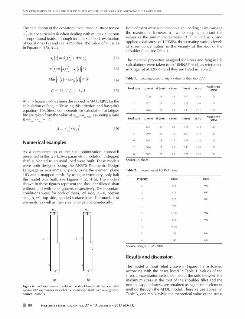
As a demonstration of the size optimization approach presented in this work, two parametric models of a stepped shaft subjected to an axial load were built. These models were both designed using the ANSYS Parametric Design Language as axisymmetric parts, using the element plane 183 and a mapped mesh. By using axisymmetry, only half the model was built, see Figures 4 a), 4 b). The models shown in these fi gures represent the shoulder fi lleted shaft without and with relief groove, respectively. The boundary conditions were, for both of them, left side, ux = 0, bottom side, uy = 0, top side, applied surface load. The number of elements, as well as their size, changed parametrically.
Both of them were subjected to eight loading cases, varying the maximum diameter, do , while keeping constant the values of the minimum diameter, di , fi llet radius, r, and applied axial stress of 120MPa, thus creating various levels of stress concentration in the vicinity of the root of the shoulder fi llet, see Table 1.
The material properties assigned for stress and fatigue life calculations were taken from 10HNAP steel, as referenced in Kluger et al. (2004), and they are listed in Table 2.
Table 1. Loading cases for eight values of the ratio do/di
Load case do (mm) di (mm) r (mm) t (mm) do / di
Axial stress (MPa)
1 27,0 25 0,3 1,00 1,08 120
2 27,5 25 0,3 1,25 1,10 120
3 28,0 25 0,3 1,50 1,12 120
Load case do (mm) di (mm) r (mm) t (mm) do / di
Axial stress (MPa)
4 28,5 25 0,3 1,75 1,14 120
5 29,0 25 0,3 2,00 1,16 120
6 29,5 25 0,3 2,25 1,18 120
7 30,0 25 0,3 2,50 1,20 120
8 30,5 25 0,3 2,75 1,22 120
Source: Authors
Table 2. Properties of 10HNAP steel
Property Value Units
Su 556 MPa
Sy 414 MPa
E 215 GPa
v 0,29 -
σ f´
1 136 MPa
τ f´
655 MPa
b -0.105 -
f−1 252 MPa
t−1 145 MPa
Source: Kluger, et al. (2004)
Results and discussion
The model without relief groove in Figure 4 a) is loaded according with the cases listed in Table 1. Values of the stress concentration factor, defi ned as the ratio between the maximum stress at the root of the shoulder fi llet and the nominal applied stress, are obtained using the fi nite element method through the APDL model. These values appear in Table 3, column 3, while the theoretical value of the stress
Figure 4. a) Axisymmetric model of the shouldered shaft, without relief groove. b) Axisymmetric model of the shouldered shaft, with relief groove.Source: Authors
INGENIERÍA E INVESTIGACIÓN VOL. 37 N.° 3, DECEMBER - 2017 (85-91) 89
GONZÁLEZ, ALCÁNTARA, SILVA, DE LA CRUZ AND OCAMPO
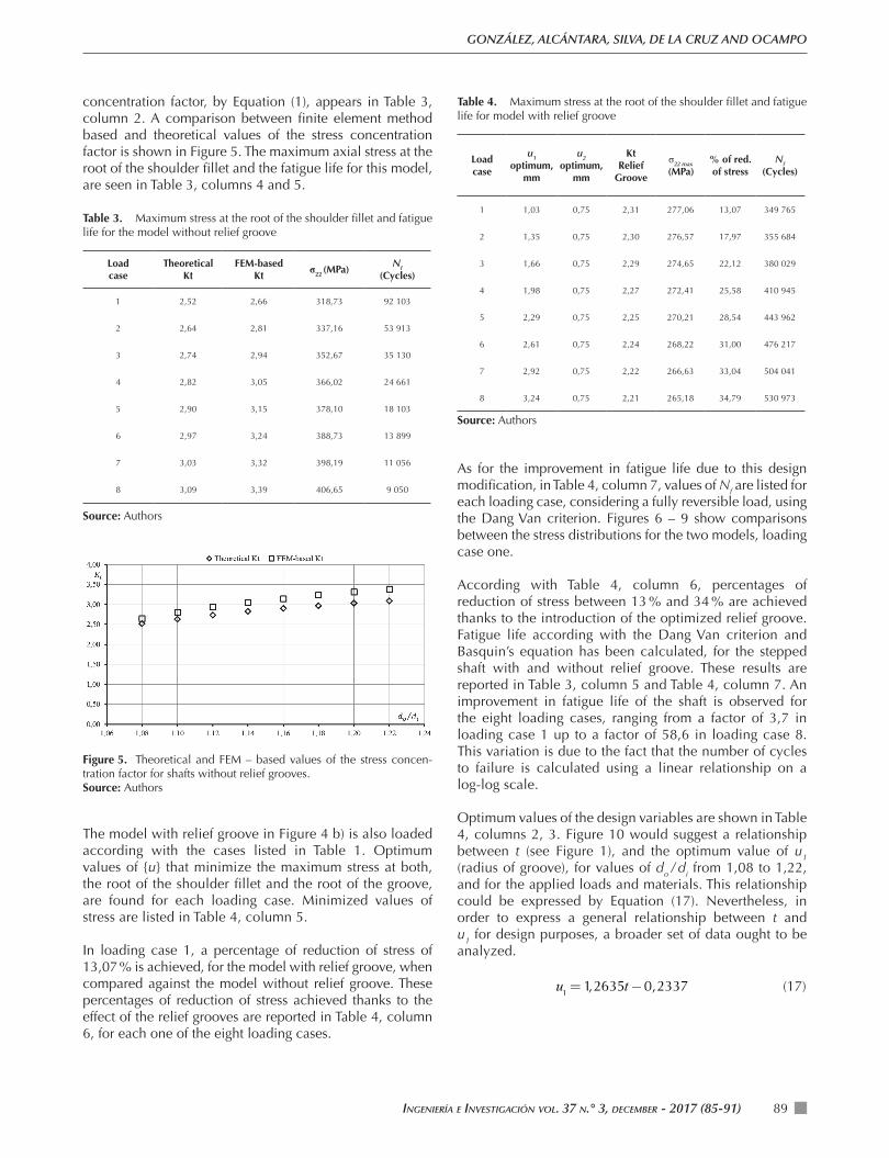
concentration factor, by Equation (1), appears in Table 3, column 2. A comparison between fi nite element method based and theoretical values of the stress concentration factor is shown in Figure 5. The maximum axial stress at the root of the shoulder fi llet and the fatigue life for this model, are seen in Table 3, columns 4 and 5.
Table 3. Maximum stress at the root of the shoulder fi llet and fatigue life for the model without relief groove
Load case
Theoretical Kt
FEM-based Kt
σ22 (MPa)Nf
(Cycles)
1 2,52 2,66 318,73 92 103
2 2,64 2,81 337,16 53 913
3 2,74 2,94 352,67 35 130
4 2,82 3,05 366,02 24 661
5 2,90 3,15 378,10 18 103
6 2,97 3,24 388,73 13 899
7 3,03 3,32 398,19 11 056
8 3,09 3,39 406,65 9 050
Source: Authors
Table 4. Maximum stress at the root of the shoulder fi llet and fatigue life for model with relief groove
Load case
u1 optimum,
mm
u2 optimum,
mm
Kt Relief
Groove
σ22 max
(MPa)% of red. of stress
Nf (Cycles)
1 1,03 0,75 2,31 277,06 13,07 349 765
2 1,35 0,75 2,30 276,57 17,97 355 684
3 1,66 0,75 2,29 274,65 22,12 380 029
4 1,98 0,75 2,27 272,41 25,58 410 945
5 2,29 0,75 2,25 270,21 28,54 443 962
6 2,61 0,75 2,24 268,22 31,00 476 217
7 2,92 0,75 2,22 266,63 33,04 504 041
8 3,24 0,75 2,21 265,18 34,79 530 973
Source: Authors
As for the improvement in fatigue life due to this design modifi cation, in Table 4, column 7, values of Nf are listed for each loading case, considering a fully reversible load, using the Dang Van criterion. Figures 6 – 9 show comparisons between the stress distributions for the two models, loading case one.
According with Table 4, column 6, percentages of reduction of stress between 13 % and 34 % are achieved thanks to the introduction of the optimized relief groove. Fatigue life according with the Dang Van criterion and Basquin’s equation has been calculated, for the stepped shaft with and without relief groove. These results are reported in Table 3, column 5 and Table 4, column 7. An improvement in fatigue life of the shaft is observed for the eight loading cases, ranging from a factor of 3,7 in loading case 1 up to a factor of 58,6 in loading case 8. This variation is due to the fact that the number of cycles to failure is calculated using a linear relationship on a log-log scale.
Optimum values of the design variables are shown in Table 4, columns 2, 3. Figure 10 would suggest a relationship between t (see Figure 1), and the optimum value of u1 (radius of groove), for values of do / di from 1,08 to 1,22, and for the applied loads and materials. This relationship could be expressed by Equation (17). Nevertheless, in order to express a general relationship between t and u1 for design purposes, a broader set of data ought to be analyzed.
u1=1,2635t−0,2337 (17)
Figure 5. Theoretical and FEM – based values of the stress concen-tration factor for shafts without relief grooves. Source: Authors
The model with relief groove in Figure 4 b) is also loaded according with the cases listed in Table 1. Optimum values of {u} that minimize the maximum stress at both, the root of the shoulder fi llet and the root of the groove, are found for each loading case. Minimized values of stress are listed in Table 4, column 5.
In loading case 1, a percentage of reduction of stress of 13,07 % is achieved, for the model with relief groove, when compared against the model without relief groove. These percentages of reduction of stress achieved thanks to the effect of the relief grooves are reported in Table 4, column 6, for each one of the eight loading cases.

SIZE OPTIMIZATION OF SHOULDER FILLETED SHAFTS WITH RELIEF GROOVES FOR IMPROVING THEIR FATIGUE LIFE
INGENIERÍA E INVESTIGACIÓN VOL. 37 N.° 3, DECEMBER - 2017 (85-91)90
Figure 7. Model without relief groove, case 1. Stress at the root of the fi llet: 318,72 MPa. Source: Authors, using Ansys Academic
Conclusions
Few studies have been devoted to the defi nition of the optimum geometry of relief grooves, when applied to shoulder fi lleted shafts in order to improve fatigue lives; therefore, an approach has been presented, aimed at minimizing the maximum axial stress at two points: the root of the shoulder fi llet and the root of the relief groove on a stepped shaft subject to axial stress.
This approach is based on the use of an in – house developed tool working with the SQP optimization algorithm within the fminimax function, and which in turn, interfaces with a parametric model for stress calculations. Finally, fatigue lives of the shaft with and without relief grooves are calculated and compared.
Figure 9. Model with relief groove, case 1. Stress at the root of the fi llet and root of the groove: 277,05 MPa. Source: Authors, using Ansys Academic.
Figure 6. Stress distribution for model without relief groove. Loading case 1.Source: Authors, using Ansys Academic.
Figure 8. Stress distribution for model with relief groove. Loading case 1. Source: Authors, using Ansys Academic.
Figure 10. Relationship between t and u1 for values of do / di from 1,08 to 1,22.Source: Authors
Percentages of reduction of stress in the range of 13 % to 34 % are achieved for values of do / di from 1,08 to 1,22.
IngenIería e InvestIgacIón vol. 37 n.° 3, december - 2017 (85-91) 91
GONZÁLEZ, ALCÁNTARA, SILVA, DE LA CRUZ AND OCAMPO
This slight change in design also causes an important improvement in fatigue life.
The novelty of the approach lies in the inclusion of an optimization algorithm for the determination of the optimum geometry of relief grooves, using an interface between MATLAB® and ANSYS.
Results are encouraging since this approach can lead to the optimization of shafts featuring various stress relieving methods, or subjected to multiaxial loads. Further developments and the application of this methodology to practical design cases must include the appropriate safety factors.
Nomenclature
u1, u2 - Design variables
Kt - Stress concentration factor
β - Equivalent stress, Dang Van criterion
τ f´ - Fatigue strength coefficient in shear
b - Fatigue strength exponent
Su - Ultimate strength
f−1 - Fatigue limit in fully reverse bending
t−1 - Fatigue limit in fully reverse torsion
σij - Macroscopic stress tensor
σH - Hydrostatic stress
Sij - Macroscopic deviatoric stress tenso
dev! ij* - Deviatoric local residual stress tensor
Sij - Mesoscopic deviatoric stress tensor
Nf - Fatigue life, number of cycles
R - Stress ratio
References
Ansys, Inc., (2016). Ansys Student retrieved from the website: http://www.ansys.com/Products/Academic/ANSYS-Student
Dang Van, K. Griveau, B., Message, O., (1989). On a new multiaxial fatigue limit criterion: theory and applications, Biaxial and Multiaxial Fatigue, EGF 3 (Edited by M. W. Brown and K. J. Miller). Mechanical Engineering Publications, London, 479 – 496.
Gauchía, A., Boada, B.L., Boada, M.J.L., Diaz, V., (2014). MATLAB applications for the practical engineer, Chapter 7: Integration of MATLAB and ANSYS for advanced analysis of vehicle structures. INTECH.
Ghelichi, R., Bernasconi, A., Guagliano, M., (2011). Geometrical optimization of notches under multiaxial fatigue loading. International Journal of Fatigue, 33, 985 – 991.
Kluger, K., Lagoda, T., (2004). Application of the Dang Van criterion for life determination under uniaxial random tension – compression with different mean values, Fatigue and Fracture of Engineering Materials and Structures, 27, 505 – 512.
Koh, S. K., Lee, S. I., Chung, S. H., Lee, K. Y., (1997). Fatigue design of an autofrettaged thick-walled pressure vessel using CAE techniques. International Journal of Pressure Vessels and Piping, 74, 19 – 32
Otsuka, Y., Bin Baron, H., Mutoh, Y., (2012). Design optimization of stress relief grooves in lever guide of pressure vessel for food processing, Open Journal of Safety Science and Technology, 2, 1 – 7.
Robles, S. I., et al., (2013). Diseño de concentradores de tensiones en elementos mecánicos, mediante las tensiones y desplazamientos superficiales, Mecánica Computacional Vol. XXXII, 3639 – 3650, C. G. García Garino, A. E. Mirasso, M. A. Storti, M. E. Tornello (Eds.) Mendoza, Argentina, 19 – 22.
Shin, J.M., Han, D.S., Lee, K.H., Han, S.H., (2014). Using stress relief grooves to reduce stress concentration on axle drive shaft, Journal of Mechanical Science and Technology, 28 (6), 2121 – 2127.
Norton, R. L., (2006). Machine design: an integrated approach. Pearson Prentice Hall. 3rd edition.
Pérez López, C., (2002). MATLAB y sus aplicaciones en las ciencias y la ingeniería, Pearson, Madrid.
Pilkey, W. D., (1997). Peterson’s stress concentration factors, Wiley. 2nd edition.
Stephens, R.I., Fatemi, A., Stephens, R.R., Fuchs, H.O., (1980). Metal fatigue in engineering, Wiley. 2nd edition.
Sonmez, F.O., (2009). Optimal shape design of shoulder fillets for flat and round bars under various loadings, Proceedings IMechE Vol. 223 Part C: J. Mechanical Engineering Science, 1741 – 1754.