SIWAREX FTA Device Manual Status 08.12 · Messages and Diagnostics 7 Programming in SIMATIC STEP 7...
221
Preface SIWAREX ® FTA Device Manual Status 08.12.2003
Transcript of SIWAREX FTA Device Manual Status 08.12 · Messages and Diagnostics 7 Programming in SIMATIC STEP 7...

Preface
SIWAREX® FTA
Device Manual Status 08.12.2003

Preface
iv SIWAREX FTA
Warning and Safety Terms This manual contains notices that are for your personal safety and to prevent damage to devices or surroundings. These notices are indicated by a warning triangle and are presented as follows depending on the degree of danger:
!
Danger means that serious material damage, severe injury or even death will result if the corresponding safety precautions are not followed carefully.
! Warning means that serious material damage, severe injury or even death can result if the corresponding safety precautions are not followed carefully.
! Caution means that material damage or minor injuries can result if the corresponding safety precautions are not followed carefully.
Caution
means that material damage can result if the corresponding safety precautions are not followed carefully.
Attention
refers to important information on the product, handling of a product or a corresponding segment of the documentation to which special attention should be given.
Qualified Personnel Installation and operation of a device may only be performed by qualified personnel. Qualified personnel in a technical safety sense within this manual are personnel that have the qualifications for installing, grounding and identifying all devices, systems and circuits according to the applicable technical safety standards. Intended Utilisation
! Warning The device may only be utilised with the replacement parts described in the catalogue and the technical description and only with foreign or external devices and components that are approved or suggested by Siemens. Fault-free and safe operation of the product depends on proper transport, proper storage, assembly, installation, operation and maintenance.
Brand names / Trademarks SIWAREX®, SIMATIC®, SIMATIC HMI® and SIMATIC NET® are registered trademarks of Siemens AG. Any other terms written as such can be trademarks for which the use by third-parties for the intended purpose can violate the rights of the owner. Copyright © Siemens AG 2003 All rights reserved Circulation or duplication of this document, utilisation and disclosure of its contents are not permitted as long as not explicitly approved. Offenders will be liable for damages. All rights, including rights created by patent grant or registration of a utility model or design, are reserved. Siemens AG Automation & Drives Dept. SIWAREX Weighing Systems A&D PI 14 Östliche Rheinbrückenstr. 50 D-76187 Karlsruhe
Disclaimer We have tested the contents of this document for compatibility with the described hardware and software. This does not exclude the possibility of discrepancies in which case, we do not guarantee the complete compatibility of this document. The information in this document is assessed regularly and any necessary corrections are included in the following revision. We are grateful for any suggestions of improvement. © Siemens AG 2003 Subject to change without notice.

SIWAREX FTA
SIWAREX FTA v
Warning and Safety Terms Contents Preface 1 Scope of Delivery 2 Product Overview 3 Hardware Planning and Assembly 4 Weighing Functions 5 Commands 6 Messages and Diagnostics 7 Programming in SIMATIC STEP 7 8 Project planning in SIMATIC PCS 7 9 Commissioning using a PC – SIWATOOL FTA 10 Firmware-Update with SIWATOOL FTA 11 Calibrating Applications 12 Accessories 13
SIWAREX FTA
Weighing Electronics for Automatic Scale Device Manual
Technical Data 14
Index 15
Abbreviations 16
Revision 12/2003 Order Number 7MH4900-2AB11

Preface
vi SIWAREX FTA
Contents
1 PREFACE............................................................................................................................................ 1-1 1.1 PURPOSE OF THIS MANUAL....................................................................................................... 1-1 1.2 FUNDAMENTAL KNOWLEDGE REQUIREMENTS.......................................................................... 1-1 1.3 SCOPE OF THIS MANUAL ........................................................................................................... 1-1 1.4 FURTHER SUPPORT.................................................................................................................... 1-2
2 SCOPE OF DELIVERY ..................................................................................................................... 2-4 2.1 SCOPE OF DELIVERY ................................................................................................................. 2-4
3 PRODUCT OVERVIEW.................................................................................................................... 3-5 3.1 GENERAL INFORMATION ........................................................................................................... 3-5 3.2 BENEFITS................................................................................................................................... 3-5 3.3 RANGE OF APPLICATION ........................................................................................................... 3-6 3.4 STRUCTURE............................................................................................................................... 3-6 3.5 FUNCTION ................................................................................................................................. 3-7 3.6 SYSTEM INTEGRATION IN SIMATIC ......................................................................................... 3-8 3.7 COMMISSIONING AND SERVICE WITH SIWATOOL FTA .......................................................... 3-9 3.8 FIRMWARE DOWNLOAD WITH SIWATOOL FTA ....................................................................3-11 3.9 READING THE STORED WEIGHING LOGS WITH SIWATOOL FTA.............................................3-11 3.10 QUICK INSTALLATION WITH SIWATOOL FTA WIZZARD.......................................................3-11
4 HARDWARE PLANNING AND ASSEMBLY ...............................................................................4-12 4.1 PLANNING THE HARDWARE IN SIMATIC ................................................................................4-13 4.2 EMC-COMPATIBLE STRUCTURE ..............................................................................................4-13
4.2.1 Definition: EMC ..............................................................................................................4-13 4.2.2 Introduction .....................................................................................................................4-13 4.2.3 Possible Effects of Interference .......................................................................................4-14 4.2.4 Coupling Mechanisms .....................................................................................................4-14 4.2.5 Five Basic Rules for Guaranteeing EMC ........................................................................4-14
4.3 ASSEMBLY ON THE PROFILE RAIL ............................................................................................4-16 4.4 CONNECTIONS AND CABLING...................................................................................................4-16
4.4.1 Connection areas for SIWAREX FTA..............................................................................4-16 4.4.2 Shield connection.............................................................................................................4-17 4.4.3 Connecting the 24 V power supply ..................................................................................4-18 4.4.4 Connection to front connector .........................................................................................4-19 4.4.5 Load cell connections ......................................................................................................4-19 4.4.6 Digital Inputs...................................................................................................................4-22 4.4.7 Counter Input...................................................................................................................4-23 4.4.8 Digital Outputs ................................................................................................................4-24 4.4.9 Analogue Output..............................................................................................................4-26 4.4.10 RS 485 Interface ..............................................................................................................4-26 4.4.11 Connecting the Remote Display by the Siebert company ................................................4-27 4.4.12 PC Connection for SIWATOOL FTA...............................................................................4-28 4.4.13 LED Indicators ................................................................................................................4-29 4.4.14 Using the Micro Memory Card........................................................................................4-30
4.5 OPERATIONAL PREPARATION ...................................................................................................4-30 5 WEIGHING FUNCTIONS................................................................................................................5-31
5.1 GENERAL INFORMATION ..........................................................................................................5-31 5.2 DS3 ADJUSTMENT PARAMETER (NAWI, AWI).......................................................................5-32
5.2.1 DS3 - Adjustment digits 0, 1, 2, 3, 4, for the zero point and Adjustment weights 1, 2, 3, 4 5-35 5.2.2 DS3 - Characteristic value range ....................................................................................5-38
SIWAREX FTA
SIWAREX FTA vii
5.2.3 DS3 – Filter sequence of the signal filter ........................................................................5-38 5.2.4 DS3 - Type of low pass filters ..........................................................................................5-39 5.2.5 DS3 - Limit frequency......................................................................................................5-39 5.2.6 DS3 - Type of average value filters .................................................................................5-39 5.2.7 DS3 - Scale Name............................................................................................................5-40 5.2.8 DS3 - Number o f weight ranges......................................................................................5-40 5.2.9 DS3 - Scale type...............................................................................................................5-40 5.2.10 DS3 - Activate zero setting on start-up............................................................................5-40 5.2.11 DS3 - Activated zero setting at start-up, if scale is tared ................................................5-40 5.2.12 DS3 - Automatic zero adjustment ....................................................................................5-40 5.2.13 DS3 - Minimum weight for weighing range 1..................................................................5-41 5.2.14 DS3 - Maximum weight for weighing range 1 .................................................................5-41 5.2.15 DS3 - Numeral Step for weighing range 1.......................................................................5-41 5.2.16 DS3 - Minimum weight for weighing range 2..................................................................5-41 5.2.17 DS3 - Maximum weight for weighing range 2 .................................................................5-41 5.2.18 DS3 - Numeral step for weighing range 2 .......................................................................5-42 5.2.19 DS3 - Minimum weight for weighing range 3..................................................................5-42 5.2.20 DS3 - Maximum weight for weighing range 3 .................................................................5-42 5.2.21 DS3 - Numeral step for weighing range 3 .......................................................................5-42 5.2.22 DS3 - Stand-still time 1....................................................................................................5-43 5.2.23 DS3 - Stand-still range 1 .................................................................................................5-43 5.2.24 DS3 - Waiting time for stand-still 1 .................................................................................5-44 5.2.25 DS3 - Maximum negative weight for zero setting at start-up ..........................................5-44 5.2.26 DS3 - Maximum positive weight for zero setting at start-up ...........................................5-44 5.2.27 DS3 - Maximum negative weight for zero setting............................................................5-44 5.2.28 DS3 - Maximum positive weight for zero setting .............................................................5-44 5.2.29 DS3 - Tare max. load T- ..................................................................................................5-44 5.2.30 DS3 - Regulations............................................................................................................5-45 5.2.31 DS3 - Unit of measurement..............................................................................................5-45 5.2.32 DS3 - Stand-still range 2 .................................................................................................5-45 5.2.33 DS3 - Stand-still time 2....................................................................................................5-45 5.2.34 DS3 - Minimum waiting time for stand-still 2 .................................................................5-45 5.2.35 DS 3 - Stand-still range 3 ................................................................................................5-46 5.2.36 DS3 - Stand-still time 3....................................................................................................5-46 5.2.37 DS3 - Minimum waiting time for stand-still 3 .................................................................5-46 5.2.38 DS 3 - Smallest set weight ∑min......................................................................................5-46 5.2.39 DS 3 - Totalising value dt ................................................................................................5-46
5.3 DS 4 BASIS PARAMETER (NAWI, AWI) .................................................................................5-47 5.3.1 DS 4 - Scale operating mode (Scale type) .......................................................................5-48 5.3.2 DS 4 - Weighing operating mode: NAWI Filling Procedure ...........................................5-48 5.3.3 DS 4 - Weighing operating mode: NAWI Emptying Procedure.......................................5-48 5.3.4 DS 4 - Weighing operating mode: AWI Single/Continuous Operation Filling................5-49 5.3.5 DS 4 - Weighing operating mode: AWI Catchw. Filling .................................................5-50 5.3.6 DS 4 - Weighing operating mode: AWI Catchw. Emptying.............................................5-51 5.3.7 DS 4 - Weighing operating mode: AWI Check ................................................................5-52 5.3.8 DS 4 - Weighing operating mode: AWI Totalising with Tare Re-weighing.....................5-53
5.4 WEIGHING STEPS – STANDARD WEIGHING PROCEDURE ...........................................................5-54 5.4.1 Processing weighing step 0 - Wait...................................................................................5-55 5.4.2 Description of Weighing step 1 – Taring/Zero setting.....................................................5-56 5.4.3 Description of Weighing step 2 – Coarse/Fine................................................................5-57 5.4.4 Description of weighing step 3 - Post dosing ..................................................................5-58 5.4.5 Description of weighing step 4 - End/Intermediate check ...............................................5-59 5.4.6 Description of weighing step 5 - Empty...........................................................................5-60 5.4.7 Description of weighing step 6 - End control AWI ..........................................................5-61 5.4.8 Description of Weighing Step 7 .......................................................................................5-62

Preface
viii SIWAREX FTA
5.4.9 DS 4 - Monitoring time for Logging ................................................................................5-62 5.4.10 DS 4 - Device for log output ............................................................................................5-62 5.4.11 DS 4 - Basis weight for the limit value 1 .........................................................................5-62 5.4.12 DS 4 - Basis weight for the limit value 2 .........................................................................5-62 5.4.13 DS 4 - Basis weight for monitoring the empty range.......................................................5-62 5.4.14 DS 4 - Empty range .........................................................................................................5-62 5.4.15 DS 4 - Switch-on weight limit value 1..............................................................................5-62 5.4.16 DS 4 - Shut-off weight limit value 1.................................................................................5-63 5.4.17 DS 4 - Switch-on weight limit value 2..............................................................................5-63 5.4.18 DS 4 - Shut-off weight limit value 2.................................................................................5-63 5.4.19 DS 4 - Switch-on weight limit value 3..............................................................................5-63 5.4.20 DS 4 - Shut-off weight limit value 3.................................................................................5-63 5.4.21 DS 4 - Minimum through-put limit value 1......................................................................5-64 5.4.22 DS 4 - Minimum through-put limit value 2......................................................................5-64 5.4.23 DS 4 - Filter depth of averaging filter for through-put calculation.................................5-64
5.5 DS 7 INTERFACES (NAWI, AWI) ...........................................................................................5-64 5.5.1 DS 7 - Source for Weight Simulation...............................................................................5-69 5.5.2 DS 7 - Decade used for rounding the decimal places of the process values....................5-69 5.5.3 DS 7 - Force in Service Operation ..................................................................................5-70 5.5.4 DS 7 - Process value 1 for fast output to the SIMATIC CPU .........................................5-70 5.5.5 DS 7 - Process value 2 for fast output to the SIMATIC CPU .........................................5-71 5.5.6 DS 7 - Definition of the process alarms 0, 1, 2, 3, 4, 5, 6, 7 ...........................................5-71 5.5.7 DS 7 - S7-FB-Life bit Monitoring Time ...........................................................................5-72 5.5.8 DS 7 - Weight for zero point (0 or 4 mA).........................................................................5-72 5.5.9 DS 7 - Weight for end value (20 mA)...............................................................................5-72 5.5.10 DS 7 - Replacement Value for the Analogue Output with OD.........................................5-72 5.5.11 DS 7 - Source for the Analogue Output ...........................................................................5-72 5.5.12 DS 7 - Current range for the Analogue Output ...............................................................5-72 5.5.13 DS 7 - RS232 Printer baud rate.......................................................................................5-73 5.5.14 DS 7 - RS232- Printer transfer control............................................................................5-73 5.5.15 DS 7 – Protocol selection for RS 485 ..............................................................................5-73 5.5.16 DS 7 - Decimal Place for Remote Display ......................................................................5-73 5.5.17 DS 7 – RS 485-Baudrate..................................................................................................5-73 5.5.18 DS 7 - RS485-character frame ........................................................................................5-74 5.5.19 DS 7 - Definition of the Digital Outputs 1, 2, 3, 4, 5, 6, 7, 8 ...........................................5-74 5.5.20 DS 7 - Level definitions for digital outputs 1 to 8............................................................5-74 5.5.21 DS 7 - Replacement value for DO 1 to 8 with Interference or Output Disable ...............5-74 5.5.22 DS 7 - Replacement values for digital outputs with operational faults ...........................5-75 5.5.23 DS 7 - Definition of the Digital Inputs 1, 2, 3, 4, 5, 6, 7..................................................5-76 5.5.24 DS 7 - Level definitions for digital inputs 1 to 7..............................................................5-76 5.5.25 DS 7 - Measurement time Pulse input .............................................................................5-76 5.5.26 DS 7 - MMC Log Overflow, MMC Trace Overflow, Target storage for trace function ..5-76 5.5.27 DS 7 - Memory segment for trace function......................................................................5-77 5.5.28 DS 7 - Memory segment for log.......................................................................................5-77 5.5.29 DS 7 - Trace function recording cycle.............................................................................5-77
5.6 DS 8 DATE / TIME (NAWI, AWI)...........................................................................................5-78 5.7 DS 9 INFO ON MODULE (NAWI, AWI)...................................................................................5-78
5.7.1 DS 9 - Info on Module .....................................................................................................5-79 5.8 DS 15 TARE ENTRY (NAWI, AWI).........................................................................................5-80
5.8.1 DS 15 - Tare Entry...........................................................................................................5-80 5.9 DS 16 WEIGHT SIMULATION ENTRY (NAWI, AWI)................................................................5-80
5.9.1 DS 16 - Weight simulation entry......................................................................................5-80 5.10 DS 17 ANALOGUE OUTPUT CONTROL (NAWI, AWI) .............................................................5-81
5.10.1 DS 17 - Ext. Definition for Analogue Output...................................................................5-81 5.11 DS 18 CONTROL DISPLAY (NAWI, AWI)...............................................................................5-81

SIWAREX FTA
SIWAREX FTA ix
5.12 DS 20 SET WEIGHT (AWI)......................................................................................................5-82 5.13 DS 21 LOAD SET VALUE (AWI) ..............................................................................................5-82 5.14 DS 22 SCALE PARAMETER 1 (AWI)........................................................................................5-83
5.14.1 DS 22 - Maximum Weighing Time...................................................................................5-83 5.14.2 DS 22 - Trailing Weight...................................................................................................5-84 5.14.3 DS 22 - Fine Weight ........................................................................................................5-84 5.14.4 DS 22 - Shut-off correction value ....................................................................................5-84 5.14.5 DS 22 - Timer pre-dosing ................................................................................................5-84 5.14.6 DS 22 –Tolerance TO1, Tolerance TU1, Tolerance TO2, Tolerance TU2...................5-84
5.15 DS 23 SCALE PARAMETER 2 (AWI) ........................................................................................5-86 5.15.1 DS 23 - Text Selection for automatic logging..................................................................5-90 5.15.2 DS 23 - Max. single set weight ........................................................................................5-90 5.15.3 DS 23 - Inhibition time - Coarse......................................................................................5-90 5.15.4 DS 23 - Fine Inhibition time ............................................................................................5-90 5.15.5 DS 23 - Inhibition time Set-Act comparison ....................................................................5-91 5.15.6 DS 23 - Default value for analogue output with course ..................................................5-91 5.15.7 DS 23 - Default value for analogue output with fine .......................................................5-91 5.15.8 DS 23 - Filter type for dosing ..........................................................................................5-91 5.15.9 DS 23 - Limit Frequency Filter for dosing ......................................................................5-91 5.15.10 DS 23 - Tare-/Zero setting mode .................................................................................5-91 5.15.11 DS 23 - Tare / Zero setting cycle .................................................................................5-92 5.15.12 DS 23 - Tare minimum weight .....................................................................................5-92 5.15.13 DS 23 - Tare max. weight ............................................................................................5-92 5.15.14 DS 23 - Time period for zero setting............................................................................5-92 5.15.15 DS 23 - Step control through digital input 1, 2, 3, 4, 5, 6, 7........................................5-93 5.15.16 DS 23 - Monitor time step control ...............................................................................5-93 5.15.17 DS 23 - Definition check stop points ...........................................................................5-93 5.15.18 DS 23 - Automatic post dosing ....................................................................................5-93 5.15.19 DS 23 - Post dosing type..............................................................................................5-93 5.15.20 DS 23 - Stop on TO1....................................................................................................5-94 5.15.21 DS 23 - Stop on TO2....................................................................................................5-94 5.15.22 DS 23 - Control pauses................................................................................................5-94 5.15.23 DS 23 - Pulse duration in pulse dosing ......................................................................5-94 5.15.24 DS 23 - Controller behaviour with dosage fault..........................................................5-95 5.15.25 DS 23 - Selection for type of controller .......................................................................5-95 5.15.26 DS 23 - Control factor Proportional controller ..........................................................5-95 5.15.27 DS 23 - Maximum one-time correction with the proportional controller....................5-96 5.15.28 DS 23 - Controller Optimum Plus ...............................................................................5-96 5.15.29 DS 23 - Controller Optimum Minus ............................................................................5-96 5.15.30 DS 23 - Set value for fine time .....................................................................................5-96 5.15.31 DS 23 - Control factor fine time controller .................................................................5-97 5.15.32 DS 23 - Overlapping time............................................................................................5-97 5.15.33 DS 23 - Emptying time.................................................................................................5-97 5.15.34 DS 23 - Maximum empty time......................................................................................5-98 5.15.35 DS 23 - Filling with coarse..........................................................................................5-98
5.16 DS 30 PROCESS VALUES 1 (NAWI, AWI) ...............................................................................5-98 5.16.1 DS 30 - NAWI-Status bits ................................................................................................5-99 5.16.2 DS 30 - AWI status flags..................................................................................................5-99 5.16.3 DS 30 - Gross process value..........................................................................................5-100 5.16.4 DS 30 - Net process value..............................................................................................5-100 5.16.5 DS 30 - Tare process value............................................................................................5-100 5.16.6 DS 30 - B/N weight ........................................................................................................5-100 5.16.7 DS 30 - B/N weight_x10 ................................................................................................5-100 5.16.8 DS 30 - Tare ..................................................................................................................5-100 5.16.9 DS 30 - Net weight.........................................................................................................5-100

Preface
x SIWAREX FTA
5.16.10 DS 30 - Pulse counter value ......................................................................................5-101 5.16.11 DS 30 - Totalising memory 1 (calibratable) ..............................................................5-101 5.16.12 DS 30 - Totalising memory 2 .....................................................................................5-101
5.17 DS 31 PROCESS VALUES 2 (NAWI, AWI) ............................................................................5-101 5.17.1 DS 31 - Through-put per second ...................................................................................5-102 5.17.2 DS 31 - Current trailing weight.....................................................................................5-102 5.17.3 DS 31 - Current fine weight...........................................................................................5-102 5.17.4 DS 31 - Unfiltered ADC value .......................................................................................5-102 5.17.5 DS 31 - Filtered ADC value after the signal filter.........................................................5-102 5.17.6 DS 31 - Filtered ADC value after the dosing filter ........................................................5-102 5.17.7 DS 31 - Current set value in load operation..................................................................5-102
5.18 DS 32 STATISTIC DATA (AWI)..............................................................................................5-102 5.18.1 DS 32 - Total number of weighing procedures..............................................................5-103 5.18.2 DS 32 - Number of weightings with tolerance check.....................................................5-103 5.18.3 DS 32 – Classification of tolerance evaluation .............................................................5-104 5.18.4 DS 32 - Set weight .........................................................................................................5-104 5.18.5 DS 32 - Average net weight value.................................................................................5-104 5.18.6 DS 32 - Standard deviation of net weight from 10.........................................................5-104 5.18.7 DS 32 - Performance per hour ......................................................................................5-104 5.18.8 DS 32 - Weightings per hour .........................................................................................5-104
5.19 DS 34 ASCII WEIGHT VALUE (NAWI, AWI) .......................................................................5-104 5.20 DS 35 CODED INFORMATION FOR CALIBRATABLE DISPLAY (NAWI, AWI) ..........................5-105 5.21 DS 40 TO 43 LOG TEXT 1 TO 4 (NAWI, AWI).....................................................................5-105 5.22 DS 44 LAST LOG (NAWI, AWI) ...........................................................................................5-107
5.22.1 DS 44 - MMC-ID ...........................................................................................................5-107 5.22.2 DS 44 - Log ID ..............................................................................................................5-107 5.22.3 DS 44 - Last log data.....................................................................................................5-107
5.23 DS 45 STRING (NAWI, AWI) ...............................................................................................5-107 5.24 DS 120/121 TRACE - DATA LOGGING ....................................................................................5-108 5.25 DS 123 DATA CONTENT MMC ..............................................................................................5-109 5.26 DS 122 LOG DATA MMC.......................................................................................................5-109
6 COMMANDS....................................................................................................................................6-111 6.1 COMMAND GROUPS ................................................................................................................6-111 6.2 COMMAND LIST......................................................................................................................6-112
7 MESSAGES AND DIAGNOSTICS................................................................................................7-119 7.1 MESSAGE TYPES.....................................................................................................................7-119 7.2 MESSAGE PATHS.....................................................................................................................7-119 7.3 RECOGNISING MESSAGES USING SIWATOOL FTA...............................................................7-120 7.4 RECOGNISING MESSAGES USING THE FB SIWA_FTA............................................................7-120 7.5 RECOGNISING MESSAGES USING THE DIAGNOSTIC ALARMS IN THE SIMATIC-CPU...............7-120 7.6 MESSAGE LISTS DATA AND OPERATING ERRORS ....................................................................7-120 7.7 MESSAGE LIST TECHNOLOGY MESSAGES................................................................................7-133 7.8 MESSAGE LIST OF OPERATING MESSAGES...............................................................................7-138
8 PROGRAMMING IN SIMATIC STEP 7......................................................................................8-141 8.1 GENERAL INFORMATION ........................................................................................................8-141 8.2 SIWAREX FTA IN THE HW CONFIGURATION ......................................................................8-141 8.3 SIWAREX FTA IN CYCLIC STEP 7 - PROGRAM ...................................................................8-142 8.4 CALL PARAMETERS FOR FB SIWA_FTA ...............................................................................8-143
8.4.1 ADDR:= 256, Input, INT...............................................................................................8-143 8.4.2 DB_SCALE:= 12, Input, INT.........................................................................................8-143 8.4.3 DB_VECTOR:= 11, Input, INT .....................................................................................8-143 8.4.4 CMD_IN:= "DB_SCALE".i_CMD_INPUT, Input, INT ................................................8-143

SIWAREX FTA
SIWAREX FTA xi
8.4.5 SIM_VAL:= "DB_SCALE".r_SIM_VALUE, Input, REAL.............................................8-143 8.4.6 ANA_OUT:= "DB_SCALE".r_ANALOG_OUT_VALUE, Input, REAL ........................8-143 8.4.7 DO_FORCE:= "DB_SCALE".b_DIG_OUTPUT_FORCE, Input, BYTE .....................8-144 8.4.8 TRANSITION:= "DB_SCALE".b_TRANSITIONS, Input, BYTE ...................................8-144 8.4.9 CMD_INPR:= "DB_SCALE".bo_CMD_IN_PROGRESS, Output, BOOL....................8-144 8.4.10 CMD_INPR:= "DB_SCALE".bo_CMD_FOK, Output, BOOL.....................................8-144 8.4.11 CMD_ERR:= "DB_SCALE".bo_CMD_ERR, Output, BOOL .......................................8-144 8.4.12 CMD_ERR_C:= "DB_SCALE".b_CMD_ERR_CODE, Output, BYTE.........................8-144 8.4.13 REF_COUNT:= "DB_SCALE".b_INFO_REFRESH_COUNT, Output, BYTE.............8-144 8.4.14 PROC_VAL1:= "DB_SCALE".r_PROCESS_VALUE1, Output, REAL ........................8-144 8.4.15 PROC_VAL2:= "DB_SCALE".w_PROCESS_VALUE2, Output, DWORD ..................8-145 8.4.16 SC_STATUS:= "DB_SCALE".dw_SCALE_STATUS, Output, DWORD .......................8-145 8.4.17 ERR_MSG:= "DB_SCALE".bo_ERR_MSG, Output, BOOL.........................................8-145 8.4.18 ERR_MSG_TYPE:= "DB_SCALE".b_ERR_MSG_TYPE, Output, BYTE .....................8-145 8.4.19 ERR_MSG_C:= "DB_SCALE".b_ERR_MSG_CODE, Output, BYTE ..........................8-145 8.4.20 FB_ERR:= "DB_SCALE".bo_FB_ERR, Output, BOOL ...............................................8-145 8.4.21 FB_ERR_C:= "DB_SCALE".b_FB_ERR_CODE .........................................................8-146 8.4.22 START_UP:= "DB_SCALE".bo_START_UP_IN_PROGRESS ....................................8-146 8.4.23 CMD_EN:= "DB_SCALE".bo_CMD_ENABLE............................................................8-146 8.4.24 ERR_MSG_Q:= "DB_SCALE".bo_ERR_MSG_QUIT..................................................8-146
8.5 ALLOCATION IN THE SCALE DB .............................................................................................8-147 8.6 CALIBRATABLE WEIGHT DISPLAY ON OP/TP/MP 170B, 270B, 370.......................................8-156
8.6.1 Functionality of the calibratable weight display ...........................................................8-157 8.6.2 Installation and Project Planning for the Calibratable Weight Display .......................8-157
9 PROJECT PLANNING IN SIMATIC PCS 7................................................................................9-160 9.1 GENERAL INFORMATION ........................................................................................................9-160 9.2 FB FOR SIWAREX FTA .......................................................................................................9-161
9.2.1 FB641 for CFC..............................................................................................................9-161 9.2.2 Function and Functionality ...........................................................................................9-161 9.2.3 Addressing and Driver Wizard ......................................................................................9-161 9.2.4 Manual/Automatic .........................................................................................................9-162 9.2.5 Data records..................................................................................................................9-163 9.2.6 Commands .....................................................................................................................9-163 9.2.7 Module error messages .................................................................................................9-163 9.2.8 Allocating message text and message class to the block parameters ............................9-164 9.2.9 Connections from SFTA (without data records)............................................................9-164 9.2.10 Calibration parameter (Data record 3): .......................................................................9-166 9.2.11 Base parameter (Data record 4): ..................................................................................9-169 9.2.12 Interface parameter (Data record 7):............................................................................9-170 9.2.13 Date/Time (Data record 8):...........................................................................................9-174 9.2.14 Application ID (Data record 9):....................................................................................9-174 9.2.15 Tare input weight (Data record 15): .............................................................................9-175 9.2.16 Weight simulation value (Data record 16): ...................................................................9-175 9.2.17 Ext. Analogue default value (Data record 17): .............................................................9-175 9.2.18 Ext. display default value (Data record 18): .................................................................9-175 9.2.19 Set value (Data record 20): ...........................................................................................9-176 9.2.20 Fill amount (Data record 21): .......................................................................................9-176 9.2.21 Fill parameter (Data record 22): ..................................................................................9-176 9.2.22 Dosing parameter (Data record 23):.............................................................................9-177 9.2.23 Process values (Data record 30):..................................................................................9-180 9.2.24 Extended process values (Data record 31):...................................................................9-182 9.2.25 Statistic data (Data record 32):.....................................................................................9-182 9.2.26 ASCII weight value (Data record 34):...........................................................................9-183 9.2.27 Encryption data (Data record 35):................................................................................9-183
Preface
xii SIWAREX FTA
9.2.28 Last log data (Data record 44):.....................................................................................9-183 9.2.29 Supplement string (Data record 45):.............................................................................9-183
9.3 EXAMPLES FOR IMAGE BLOCKS FOR SIWAREX FTA............................................................9-184 9.3.1 Faceplate display in OS.................................................................................................9-184 9.3.2 Faceplate Creation ........................................................................................................9-185
10 COMMISSIONING USING A PC – SIWATOOL FTA...........................................................10-188 10.1 GENERAL .............................................................................................................................10-188 10.2 WINDOWS AND FUNCTIONS OF THE SIWATOOL FTA ........................................................10-188 10.3 OFFLINE PROJECT PLANNING ...............................................................................................10-188 10.4 ONLINE OPERATION .............................................................................................................10-189 10.5 ASSISTANCE .........................................................................................................................10-190
11 FIRMWARE-UPDATE WITH SIWATOOL FTA...................................................................11-191 11.1 ADVANTAGES OF THE FIRMWARE-UPDATE ..........................................................................11-191
12 CALIBRATING APPLICATIONS ............................................................................................12-193 12.1 GENERAL NOTE....................................................................................................................12-193 12.2 CALIBRATABLE MAIN WEIGHT DISPLAY ...............................................................................12-194 12.3 READING THE CALIBRATABLE LOGS WITH SIWATOOL FTA..............................................12-194
13 ACCESSORIES............................................................................................................................13-195
14 TECHNICAL DATA....................................................................................................................14-198 14.1 24 V POWER SUPPLY ............................................................................................................14-198 14.2 POWER SUPPLY FROM S7 BACK-PLANE BUS..........................................................................14-198 14.3 LOAD CELL CONNECTION .....................................................................................................14-198 14.4 ANALOGUE OUTPUT .............................................................................................................14-199 14.5 DIGITAL INPUTS (DI), DIGITAL OUTPUTS (DO) ....................................................................14-199 14.6 COUNTER INPUT CI ..............................................................................................................14-200 14.7 RS 232C INTERFACE ............................................................................................................14-200 14.8 RS 485 INTERFACE...............................................................................................................14-200 14.9 DIMENSIONS AND WEIGHT ...................................................................................................14-201 14.10 MECHANICAL REQUIREMENTS AND DATA ........................................................................14-201 14.11 ELECTRICAL, EMC AND CLIMATIC REQUIREMENTS .........................................................14-201
14.11.1 Electrical protection and safety requirements.........................................................14-201 14.11.2 Electromagnetic Compatibility ................................................................................14-202
14.12 ENVIRONMENTAL CONDITIONS.........................................................................................14-202 15 INDEX ...........................................................................................................................................15-204
16 ABBREVIATIONS ......................................................................................................................16-207
Images
IMAGE 3-1 AREAS OF APPLICATION SIWAREX FTA IN THE PRODUCTION CHAIN.............................. 3-8 IMAGE 3-2 CONFIGURATION SIMATIC S7/PCS7 WITH SIWAREX FTA .......................................... 3-9 IMAGE 3-3 SIWATOOL FTA OVERVIEW .........................................................................................3-10 IMAGE 3-4 WEIGHING PROCEDURE PROGRESS DISPLAYED FROM THE TRACING IN SIWAREX FTA 3-11 IMAGE 4-1 SIWAREX FTA FRONT VIEW.........................................................................................4-17 IMAGE 4-2 SHIELD CLAMP ASSEMBLY................................................................................................4-18 IMAGE 4-3 LOAD CELL CONNECTION IN 4-WIRE SYSTEM....................................................................4-21 IMAGE 4-4 LOAD CELL CONNECTION IN 6-WIRE SYSTEM....................................................................4-21 IMAGE 4-5 DIGITAL INPUTS................................................................................................................4-23 IMAGE 4-6 COUNTER INPUT ...............................................................................................................4-24

SIWAREX FTA
SIWAREX FTA xiii
IMAGE 4-7 DIGITAL OUTPUTS ............................................................................................................4-25 IMAGE 4-8 ANALOGUE OUTPUT .........................................................................................................4-26 IMAGE 4-9 RS 485 CONNECTION........................................................................................................4-27 IMAGE 4-10 S11 DISPLAY CONNECTION..............................................................................................4-28 IMAGE 4-11 PC CONNECTION..............................................................................................................4-29 IMAGE 5-1 ADJUSTMENT DIGITS AND WEIGHT VALUE........................................................................5-37 IMAGE 5-2 LINEARISATION OF THE SCALE'S CHARACTERISTIC CURVE ..............................................5-38 IMAGE 5-3 DIGITAL LOW PASS FILTER STEP RESPONSE.......................................................................5-39 IMAGE 5-4 STAND-STILL MONITORING...............................................................................................5-43 IMAGE 5-5 WEIGHING STEPS IN AUTOMATIC FILLING OPERATION SAWI ...........................................5-49 IMAGE 5-6 WEIGHING STEPS FOR CATCH WEIGHING WITH FILLING AWI............................................5-50 IMAGE 5-7 WEIGHING STEPS FOR CATCH WEIGHING WITH EMPTYING AWI .......................................5-51 IMAGE 5-8 WEIGHING STEPS FOR A WEIGHT RECORDING (CHECK) AWI ............................................5-52 IMAGE 5-9 WEIGHING STEPS FOR AWI TOTALISING ..........................................................................5-53 IMAGE 5-10 DEFINING LIMIT VALUE PARAMETERS ..............................................................................5-63 IMAGE 5-11 TOLERANCE EVALUATION PROGRESS BY TIME WITH TU1 STATUS ...................................5-85 IMAGE 5-12 AUTOMATIC POST DOSING WITH TOLERANCE TU1 ...........................................................5-95 IMAGE 8-1 FB SIWA_FTA CALL PARAMETERS. .............................................................................8-142 IMAGE 8-2 CALIBRATABLE DISPLAY IN TP/OP ................................................................................8-157 IMAGE 8-3 "SECURE OUTPUT" FUNCTION IN PROTOOL ....................................................................8-158 IMAGE 8-4 PARAMETER OF THE SIWAREX FTA OCX...................................................................8-159 IMAGE 9-1 SFTA FUNCTION BLOCK IN CFC ....................................................................................9-162 IMAGE 9-2 STANDARD VIEW FOR SIWAREX FTA..........................................................................9-184 IMAGE 9-3 DOSING DATA VIEW........................................................................................................9-185 IMAGE 9-4 SERVICE VIEW ................................................................................................................9-185 IMAGE 9-5 COMBO-BOX WITH SEVERAL ENTRIES.............................................................................9-186 IMAGE 9-6 COMMAND SELECTION ...................................................................................................9-187 IMAGE 9-7 STANDARD VIEW ............................................................................................................9-187 IMAGE 10-1 SIWATOOL FTA WINDOW DISTRIBUTION ................................................................10-189 IMAGE 11-1 DOWNLOADING FIRMWARE WITH SIWATOOL FTA...................................................11-192 IMAGE 12-1 READ THE CALIBRATABLE MEMORY WITH SIWATOOL FTA......................................12-194
Tables
TABLE 1-1 VALIDITY OF THIS MANUAL.............................................................................................. 1-1 TABLE 1-2 CHAPTER OVERVIEW......................................................................................................... 1-2 TABLE 4-1 REQUIREMENTS FOR N SIWAREX FTA ..........................................................................4-13 TABLE 4-2 POWER SUPPLY CONNECTION ...........................................................................................4-19 TABLE 4-3 LOAD CELL CONNECTION .................................................................................................4-19 TABLE 4-4 DIGITAL INPUT CONNECTIONS ..........................................................................................4-22 TABLE 4-5 PULSE ENCODER CONNECTION..........................................................................................4-23 TABLE 4-6 DIGITAL OUTPUT CONNECTIONS .......................................................................................4-25 TABLE 4-7 ANALOGUE OUTPUT CONNECTIONS ..................................................................................4-26 TABLE 4-8 RS 485 CONNECTIONS......................................................................................................4-26 TABLE 4-9 PC CONNECTION..............................................................................................................4-28 TABLE 4-10 INDICATORS (LED) ..........................................................................................................4-29 TABLE 5-1 DS3 ALLOCATION............................................................................................................5-35 TABLE 5-2 DS4 ALLOCATION............................................................................................................5-48 TABLE 5-3 SIGNAL STATES IN STEP 0 .................................................................................................5-55 TABLE 5-4 SIGNAL STATES IN STEP 1 .................................................................................................5-56 TABLE 5-5 SIGNAL STATES IN STEP 2 .................................................................................................5-57 TABLE 5-6 SIGNAL STATES IN STEP 3 .................................................................................................5-58 TABLE 5-7 SIGNAL STATES IN STEP 4 .................................................................................................5-59 TABLE 5-8 SIGNAL STATES IN STEP 5 .................................................................................................5-60

Preface
xiv SIWAREX FTA
TABLE 5-9 SIGNAL STATES IN STEP 6 .................................................................................................5-61 TABLE 5-10 DS 7 ALLOCATION...........................................................................................................5-69 TABLE 5-11 SELECTION LIST FOR PROCESS VALUES.............................................................................5-71 TABLE 5-12 TRACE ELEMENT DATA.....................................................................................................5-78 TABLE 5-13 DS 8 ALLOCATION...........................................................................................................5-78 TABLE 5-14 DS 9 ALLOCATION...........................................................................................................5-79 TABLE 5-15 DS 15 ALLOCATION.........................................................................................................5-80 TABLE 5-16 DS 16 ALLOCATION.........................................................................................................5-80 TABLE 5-17 DS 17 ALLOCATION.........................................................................................................5-81 TABLE 5-18 DS 18 ALLOCATION.........................................................................................................5-82 TABLE 5-19 DS 20 ALLOCATION.........................................................................................................5-82 TABLE 5-20 DS 21 ALLOCATION.........................................................................................................5-82 TABLE 5-21 DS 20 ALLOCATION.........................................................................................................5-83 TABLE 5-22 TOLERANCE INFORMATION EVALUATION .........................................................................5-86 TABLE 5-23 DS 23 ALLOCATION.........................................................................................................5-90 TABLE 5-24 DS 30 ALLOCATION.........................................................................................................5-98 TABLE 5-25 DS 30 - NAWI STATUS BITS ............................................................................................5-99 TABLE 5-26 DS 30 - AWI STATUS FLAGS..........................................................................................5-100 TABLE 5-27 DS 31 ALLOCATION.......................................................................................................5-102 TABLE 5-28 DS 32 ALLOCATION.......................................................................................................5-103 TABLE 5-29 DS 34 ALLOCATION.......................................................................................................5-104 TABLE 5-30 DISPLAY EXAMPLE FOR WEIGHT DISPLAY.......................................................................5-105 TABLE 5-31 DS 35 ALLOCATION.......................................................................................................5-105 TABLE 5-32 DS 40 ALLOCATION.......................................................................................................5-106 TABLE 5-33 PROCESS VALUES FOR LOG FIELD ALLOCATION ..............................................................5-106 TABLE 5-34 DS 44 ALLOCATION.......................................................................................................5-107 TABLE 5-35 DS 45 ALLOCATION.......................................................................................................5-107 TABLE 5-36 CONSTRUCTION OF A LOGGING ELEMENT .......................................................................5-108 TABLE 5-37 OVERVIEW OF MMC DATA............................................................................................5-109 TABLE 5-38 MMC LOG......................................................................................................................5-110 TABLE 6-1 SIWAREX FTA COMMAND LIST ...................................................................................6-117 TABLE 6-2 COMMAND GROUPS OF SIWAREX FTA........................................................................6-118 TABLE 7-1 LIST OF DATA AND OPERATING ERRORS ........................................................................7-132 TABLE 7-2 LIST OF TECHNOLOGY MESSAGES..................................................................................7-137 TABLE 7-3 LIST OF OPERATING MESSAGES .....................................................................................7-140 TABLE 8-1 SCALE DB CONSTRUCTION ............................................................................................8-156 TABLE 9-1 CFC - MESSAGE TYPES ..................................................................................................9-163 TABLE 9-2 CFC – MESSAGE TEXT FROM SFTA...............................................................................9-164 TABLE 9-3 CFC – SFTA CONNECTION WITHOUT DATA RECORDS ...................................................9-166 TABLE 9-4 CFC – SFTA CONNECTIONS – DS3 INPUTS ...................................................................9-168 TABLE 9-5 CFC – SFTA CONNECTIONS – DS3 OUTPUTS ................................................................9-169 TABLE 9-6 CFC – SFTA CONNECTIONS – DS4 INPUTS ...................................................................9-170 TABLE 9-7 CFC – SFTA CONNECTIONS – DS4 OUTPUTS ................................................................9-170 TABLE 9-8 CFC – SFTA CONNECTIONS – DS7 INPUTS ...................................................................9-172 TABLE 9-9 CFC – SFTA CONNECTIONS – DS7 OUTPUTS ................................................................9-174 TABLE 9-10 CFC – SFTA CONNECTIONS – DS8................................................................................9-174 TABLE 9-11 CFC – SFTA CONNECTIONS – DS9................................................................................9-175 TABLE 9-12 CFC – SFTA CONNECTIONS – DS15..............................................................................9-175 TABLE 9-13 CFC – SFTA CONNECTIONS - DS16 .............................................................................9-175 TABLE 9-14 CFC – SFTA CONNECTIONS – DS17..............................................................................9-175 TABLE 9-15 CFC – SFTA CONNECTIONS – DS18..............................................................................9-175 TABLE 9-16 CFC – SFTA CONNECTIONS – DS20..............................................................................9-176 TABLE 9-17 CFC – SFTA CONNECTIONS – DS21..............................................................................9-176 TABLE 9-18 CFC – SFTA CONNECTIONS – DS22 MANUAL INPUTS...................................................9-176 TABLE 9-19 CFC – SFTA CONNECTIONS – DS22 AUTOMATIC INPUTS..............................................9-176

SIWAREX FTA
SIWAREX FTA xv
TABLE 9-20 CFC – SFTA CONNECTIONS - OUTPUTS .........................................................................9-177 TABLE 9-21 CFC – SFTA CONNECTIONS – DS23 INPUTS .................................................................9-178 TABLE 9-22 CFC – SFTA CONNECTIONS – DS23 OUTPUTS ..............................................................9-180 TABLE 9-23 CFC – SFTA CONNECTIONS – DS30 OUTPUTS ..............................................................9-182 TABLE 9-24 CFC – SFTA CONNECTIONS – DS31 OUTPUTS ..............................................................9-182 TABLE 9-25 CFC – SFTA CONNECTIONS – DS32 OUTPUTS ..............................................................9-183 TABLE 9-26 CFC – SFTA CONNECTIONS – DS34 OUTPUTS ..............................................................9-183 TABLE 9-27 CFC – SFTA CONNECTIONS – DS35 OUTPUTS ..............................................................9-183 TABLE 9-28 CFC – SFTA CONNECTIONS – DS44 OUTPUTS ..............................................................9-183 TABLE 9-29 CFC – SFTA CONNECTIONS – DS45 INPUTS .................................................................9-183 TABLE 9-30 CFC – SFTA CONNECTIONS – DS45 OUTPUTS ..............................................................9-184 TABLE 14-1 DATA: 24 V POWER SUPPLY.........................................................................................14-198 TABLE 14-2 DATA: POWER SUPPLY FROM S7 BACK-PLANE BUS ......................................................14-198 TABLE 14-3 DATA: LOAD CELL CONNECTION ..................................................................................14-199 TABLE 14-4 DATA: ANALOGUE OUTPUT ..........................................................................................14-199 TABLE 14-5 DATA: DIGITAL INPUTS, DIGITAL OUTPUTS..................................................................14-200 TABLE 14-6 DATA: COUNTER INPUT CI ...........................................................................................14-200 TABLE 14-7 DATA: RS 232C INTERFACE.........................................................................................14-200 TABLE 14-8 DATA: RS 485 INTERFACE ...........................................................................................14-200 TABLE 14-10 DATA: DIMENSIONS AND WEIGHT............................................................................14-201 TABLE 14-11 DATA: MECHANICAL REQUIREMENTS ......................................................................14-201 TABLE 14-12 DATA: ELECTRICAL PROTECTION AND SAFETY REQUIREMENTS ...............................14-202 TABLE 14-13 DATA: ELECTROMAGNETIC COMPATIBILITY ............................................................14-202 TABLE 14-14 DATA: CLIMATIC REQUIREMENTS ............................................................................14-203


Preface
SIWAREX FTA 1-1
1 Preface
1.1 Purpose of This Manual
All of the information required to construct and operation the SIWAREX FTA is found in this manual.
1.2 Fundamental Knowledge Requirements
To understand this manual, a general knowledge of SIMATIC automation technology is required. Weighing technology is also beneficial.
1.3 Scope of this Manual
This manual refers to the SIWAREX FTA module: Type Name Order number from product status
(Version) SIWAREX FTA SIWAREX
Flexible Technology Automatic Weighing Instrument*
7MH4900-2AA01 HW V1.0.0
FW V.1.1.1
Table 1-1 Validity of This Manual
*The name corresponds with the naming conventions of the OIML - Organisation Internationale de Metrologie Legale and means „Automatic Weighing Instrument“.
Note This manual contains the description of all modules that are valid at the time of publication.
We reserve the right to deliver production information along with new modules or modules with a newer product status that contains the current information on the module.

Preface
1-2 SIWAREX FTA
The layout of this manual is based on activities that must be performed in the scope of project planning, commissioning, operation and service / maintenance.
Chapter Description of Content 1 Preface Notes on using this manual 2 Scope of Delivery Description of the SIWAREX FTA scope of
delivery 3 Preface Overview of
-Structure - Functionality - System integration of SIWAREX FTA
4 Hardware Planning and Assembly
Description - of individual hardware components - of structure and installation - of connections - of operating preparation.
5 Weighing Functions Description of all weighing parameters and corresponding functions.
6 Commands Description of commands that can be executed by SIWAREX FTA
7 Messages and Diagnostics
Description of error messages with notes on problem solutions
8 Programming in SIMATIC STEP 7
Description of data exchange with the SIMATIC CPU. This chapter is only meant for users who wish to write their own application software.
9 Project planning in SIMATIC PCS 7
Description for the PCS 7 project planning package
10 Commissioning using a PC – SIWATOOL FTA
Description - Software installation - Software functions
11 Firmware-Update with SIWATOOL FTA
Description - Software installation - Software functions
12 Calibrating Applications Description of conditions for calibration 13 Accessories Ordering information for optional components
such as: - Digital remote display - Micro Memory Card - Exi-Interface
Technical Data 15 Index 16 Abbreviations
Table 1-2 Chapter Overview
1.4 Further Support
Do you have more questions about using the SIWAREX FTA? Then please contact your Siemens representative in the office or business location that is responsible for your area or technical support for SIWAREX - Tel.: +49 (0)721 595 2811.

Preface
SIWAREX FTA 1-3
Updated information on SIWAREX Weighing Technology can be found on the respective Internet Site.
http://www.siwarex.com

Scope of Delivery
SIWAREX FTA 2-4
2 Scope of Delivery
2.1 Scope of Delivery
A bus connector for the SIMATIC bus, the conformity details from the manufacturer and a sheet of additional product information belong to the SIWAREX FTA scope of delivery.
For planning your work with the SIWAREX FTA, you will need:
- The SIWAREX FTA project planning package for SIMATIC S7
or
- The SIWAREX FTA project planning package for SIMATIC PCS7
These are not components included in the scope of delivery and must be ordered separately.
The corresponding project planning package is combined of the following components:
- SIWATOOL commissioning program for Windows
- Set-up for the installation of the module in the SIMATIC Manager hardware catalogue
- Standard software for operating the SIWAREX FTA in SIMATIC S7
- Manual in several languages
- Set-up for PCS7 Library (Project planning package for PCS7 only)
- SIWAREX FTA OCX – AddOn for ProTool for project planning with the calibration display (TP/OP/MP 170B/270/370)
Application sample software can be very helpful for the first programming steps. This software can be downloaded, free-of-charge over the Internet (www.siwarex.com).
With software packages:
- SIWAREX Multiscale for batch systems
- SIWAREX Multifill for filling/bagging operations there is a specially designed STEP 7 software available which enables a very effective system software development.
The required optional accessories are provided in chapter 13 Accessories.

Product Overview
SIWAREX FTA 3-5
3 Product Overview
3.1 General Information
SIWAREX FTA (Flexible Technology, Automatic Weighing Instrument) is a versatile and flexible weighing module which can be utilised wherever a scale should fulfil its tasks automatically. Automatic scale operation is characterised by an weighing procedure performed automatically according to a defined plan.
The function module (FM) SIWAREX FTA is integrated in SIMATIC and uses all features of the modern automation system such as integrated communication, diagnostics system and project planning tools to its advantage.
The scale functionality of the SIWAREX FTA includes the non-automatic scale (Non automatic weighing instrument conforming with OIML R-76), the automatic scale for balancing (Automatic gravimetric filling Instrument conforming with OIML R-61), the automatic scale for catch weighing (Automatic catch weighing instrument conforming with OIML R-51) and the automatic scale for discontinuous totalising (Discontinuous totalising automatic weighing instrument conforming with OIML R-107)
3.2 Benefits
SIWAREX FTA is characterised by a few clear advantages:
o Uniform structure and universal communication through the integration in the SIMATIC S7 and SIMATIC PCS7
o Uniform project planning with SIMATIC
o Direct application in SIMATIC automation system
o Application in the decentralised system concept by connecting to PROFIBUS DP through ET 200M
o Weight measurement or force to resolutions of 16 million parts
o Precision of 3 x 6000d, calibratable (0.5 µV per e)
o Calibratable display with SIMATIC HMI standard operator panels
o Measurement rates of internal 2.5 msec, external 10 msec
o Exact dosage switching signals (< 1 msec)
o Several dosage speeds
o Smooth or step controlled dosage control
o Parameter definable inputs and outputs
o Automatic weighing operation parameter setting for different applications

3-6 SIWAREX FTA
o Flexible adjustment for various SIMATIC requirements
o Simple parameter definition with the SIWATOOL program through the RS 232 interface
o Theoretical adjustment without any adjustment weights possible
o Module exchanging without readjusting the scale is possible
o Scale status recording
o Intrinsically safe load cell supply for Ex-Zone 1 (optional)
o Application in Ex-Zone 2
o Extensive diagnostic functions
3.3 Range of Application
SIWAREX FTA is the optimal solution wherever weighing technology requires high speed and precision. Because of the high resolution (3 x 6000 d, calibratable), scales can be built to work precisely over broad areas. Calibratable weighing systems, whether a filling system, unloading station, bagging operation, rotopacker, mixer or control stations can be constructed with the SIWAREX FTA. Typical fields of application are e.g.:
o Liquid filling
o Bagging in a packaging system
o Weighing catch levels as well as level decrease weighing and fill weighing
o Catch level testing
o Material loading with totalising
3.4 Structure SIWAREX FTA is a function module (FM) of the SIMATIC S7-300 and can be read directly on the SIMATIC S7-300- or ET 200M bus board. Installation / cabling efforts for the 80 mm wide module are simplified with the profile rail assembly (snap-in technology).
Connecting load cells, power supply and the serial interface is all done through the 40 pin standard front connector.
Operation of the SIWAREX FTA in SIMATIC guarantees complete integration of weighing technology in the automation system.

Product Overview
SIWAREX FTA 3-7
3.5 Function The primary task of the SIWAREX FTA consists of the precise measurement of the current weight values in up to three measurement ranges and the exact control of the weighing procedure. The control of the weighing procedure is completely run from the weighing module as if in separately constructed weighing electronics. The integration in SIMATIC enables the progress of the weighing procedure to be influenced directly from the PLC program however. This enables reasonable task distribution: The extremely fast weighing functions are performed in the SIWAREX module, latching and signal linking is done in the PLC.
There are different automatic weighing procedures for which SIWAREX FTA can be configured optimally by defining the corresponding parameters.
The following operating modes can be defined:
- Non Automatic Weighing Instrument – conforming with OIML R-76
- Automatic Gravimetric Filling Instrument – conforming with OIML R-61 (AWI)
- Automatic catch weighing instrument – conforming with OIML R51 (AWI)
- Automatic Totalising Filling Instrument- totalising – conforming with OIML R 107 (AWI)
During the weighing procedure, SIWAREX FTA monitors and controls a multitude of signals. The optimised system internal data exchange enables a direct evaluation of weighing signals and states in the PLC program.
The weighing procedure influence on the PLC enables a flexible adjustment to suit the changes in the system technology.
SIWAREX FTA is already adjusted in-house. Therefore, the scale can be adjusted to theoretical settings without using any adjustment weights and modules can be exchanged without readjusting the scale. Exchanging modules during running operation is also possible when working with “active bus modules”.
The SIWAREX FTA has two serial interfaces. An RS 485 interface is used for connecting digital remote displays. A PC can be connected to the RS 232 interface for setting SIWAREX FTA parameters.
The weighing module SIWAREX FTA can also be used in explosion hazard areas (zones 21 and 22). Load cells are supplied with inherent safety with zone 1 applications using an optional Ex-interface SIWAREX IS.

3-8 SIWAREX FTA
Image 3-1 Areas of application SIWAREX FTA in the production chain
3.6 System Integration in SIMATIC
SIWAREX FTA is completely integrated in the SIMATIC S7 and SIMATIC PCS7. The user is absolutely free to configure his automation solution including the weighing application as desired. The optimal solution can be created for small, medium and large systems by selectively combining the SIMATIC components. The project planning package and the example applications for SIMATIC can help you to quickly and efficiently create customer specific or branch specific solutions. The following image shows a typical assembly for a medium sized system.
For project planning with SIMATIC PCS 7, the completed function block FB SIWA for the automation system and the graphic blocks for the operator station are used.

Product Overview
SIWAREX FTA 3-9
Image 3-2 Configuration SIMATIC S7/PCS7 with SIWAREX FTA
3.7 Commissioning and Service with SIWATOOL FTA
For commissioning, there is a special program SIWATOOL FTA for Windows operating systems.
The program enables commissioning of the scale without having to understand automation technology. During a service procedures, you can analyse the processes in the scale and test them with the help of a PC. Reading the diagnostics buffer from the SIWAREX FTA is very helpful in analysing events.
Besides complete access to all parameters, memory or print-outs of the weighing file, the program can create weighing curves as well.
SIWATOOL FTA can also be used for reading the contents of the calibratable records from the calibratable scale memory.
The following image shows the structure of the individual program windows.

3-10 SIWAREX FTA
Image 3-3 SIWATOOL FTA Overview
Not only does the SIWATOOL FTA support the user for program entry. Analysing the diagnostics buffer, the contents of which can be saved together with the parameters after reading from the module is also very helpful.
A trace mode exists in the SIWAREX FTA module for optimising weighing progress. The recorded data can be displayed in a curve diagram using the MS Excel.
The following image shows the progress of a weighing procedure displayed with the SIWATOOL FTA.

Product Overview
SIWAREX FTA 3-11
Image 3-4 Weighing procedure progress displayed from the tracing in SIWAREX FTA
3.8 Firmware Download with SIWATOOL FTA
Another feature of the SIWATOOL FTA program helps loading a new firmware version for SIWAREX FTA on-site. It allows you to perform firmware upgrades at any time and from anywhere.
3.9 Reading the stored weighing logs with SIWATOOL FTA
The weighing logs are stored on an MMC (Micro Memory Card) that is inserted into the SIWAREX FTA for the period of time defined in the weights and measures act. If a person disagrees with the results of a certain weighing procedure, the weighing data for that weighing procedure can be reconstructed from the MMC memory.
3.10 Quick Installation with SIWATOOL FTA Wizzard
The Function Wizzard is very helpful in defining parameters for the first time. The user answers several questions provided in dialogs and the program defines the correct parameters for SIWAREX FTA based on these answers.

4-12 SIWAREX FTA
4 Hardware Planning and Assembly
! Warning Notes
This chapter contains information required for hardware planning, assembly and preparations for operation.
The technical safety information is to be strictly adhered to.
! Warning
Unqualified intervention in the device/system or not adhering to the warning notices can result in serious injury or damage to equipment. Only qualified personnel are permitted access to the operational components of this device / system.
! Warning
The unit has been developed, manufactured, tested and documented according to the corresponding safety standards. The device itself will not cause any danger to equipment or personal health under normal circumstances.
! Danger
Installation and start-up operation is not permitted until it is guaranteed that the machine in which these components are to be integrated corresponds with the guidelines 89/392/EWG.

Hardware Planning and Assembly
SIWAREX FTA 4-13
4.1 Planning the Hardware in SIMATIC
SIWAREX FTA is a function module (FM) in the SIMATIC S7 300 automation system. It can be installed in all places that are constructed for function modules.
Utilisation with the SIMATIC S7 300 is possible in central operation, in an expansion device or decentralised in the ET 200M system.
Operation in the SIMATIC S7 400 is only possible decentralised in the ET 200M system. In this case, the active back-plane bus can be used.
In estimating the maximum number of SIWAREX FTA's that can be integrated within one system, the following information may be helpful.
Total width Current requirements (5V) from SIMATIC back-plane bus
Application memory requirements in the SIMATIC CPU
n x 80 mm n x 50 mA 3500 Bytes + n x 1200 Bytes
Table 4-1 Requirements for n SIWAREX FTA
Max. amount in central operation – 8 SIWAREX FTA
Max. amount with multi-line expansion – 8 SIWAREX FTA per line
Max. amount in system ET 200M – 7 SIWAREX FTA per station
Selecting the suitable SIMATIC CPU, the SIMATIC HMI (Human Machine Interface) and communication modules does not only depend on SIWAREX FTA requirements but also on the overall job that the automation system has to perform.
4.2 EMC-Compatible Structure
SIWAREX FTA is a high-precision measurement device which has to dependably measure the slightest signal. Proper assembly and cabling is an absolute must for interference free operation.
4.2.1 Definition: EMC
EMC (Electromagnetic Compatibility) describes the ability of an electrical device to function in a defined electromagnetic environment without being influenced by its surroundings and without negatively influencing the surroundings.
4.2.2 Introduction
Although SIWAREX FTA was developed for use in industrial environments and meets high EMC specifications, you should do some EMC planning before

4-14 SIWAREX FTA
installing your controller to determine and take into account any possible interference sources.
4.2.3 Possible Effects of Interference
Electromagnetic interference can influence the automation system and SIWAREX FTA in various ways:
- Electromagnetic fields that have direct influence on the system
- Interference that infiltrates the environment through the bus signals (PROFIBUS-DP etc.)
- Interference through process cabling (e.g. measurement lines)
- Interference infiltrating the system through the power supply and/or protective ground
Error-free functionality of the SIWAREX FTA can be influenced by interference.
4.2.4 Coupling Mechanisms
Depending on the means of distribution (conductive or non-conductive bound) and the distance between the interference source and the device, interference can be introduced through four different coupling mechanisms into the automation system.
Galvanic coupling
Capacitive coupling
Inductive coupling
Radiation coupling
4.2.5 Five Basic Rules for Guaranteeing EMC
If you follow these five basic rules, EMC can be guaranteed in most cases!
Rule 1: Large conductive grounding surface connections
Ensure that while installing the automation devices, a well-made ground connection is made between the inactive metal components (see following section).
Connect all inactive metal components and low-impedance components with ground (broad cross-section).
Use screw connections on painted or anodised metal surfaces either with special contact washers or remove the insulated protective surface in the contact areas.
Do not use aluminium if at all possible for ground connections. Aluminium oxidises easily and is therefore less suitable for grounding connections.
Find a central location for connections between the grounding point and the ground wiring system.

Hardware Planning and Assembly
SIWAREX FTA 4-15
Rule 2: Proper and organised wiring
Separate the cabling into groups (high-voltage lines, power supply lines, signal lines, ground wiring, data lines, etc.).
Run the high-voltage lines and ground wiring or data cables in separate channels or bundles.
Run measurement lines as close to grounding surfaces as possible (e.g. support beams, metal rails, cabinet panels).
Rule 3: Fasten cable shielding
Ensure that the cable shielding is connected properly.
Use shielded data wiring only. The shielding must be fastened to ground using a large surface area on both ends.
The shielding of measurement lines must be fastened to ground on both ends.
Run cable shielding directly under the SIWAREX FTA on the shielding channelling. The shielding is to be run to the connection terminal.
The connection between the shielding rail / ground rail and the cabinet /housing must be low impedance.
Use metallic or metal-plated connector housings for the shielded data lines.
Rule 4: Special EMC measures
All inductivity that is to be controlled should be connected with suppressors.
Use interference suppressed fluorescent lighting or incandescent lamps for illuminating cabinets or housings in the immediate vicinity of your controller.
Rule 5: Uniform reference potential
Create a uniform reference potential and ground all electrical operational elements.
Run sufficiently dimensioned potential equalizing cabling if potential differences exist or are to be expected between system components in the system. A potential equalisation is mandatory for Ex applications.

4-16 SIWAREX FTA
4.3 Assembly on the Profile Rail
When assembling the SIMATIC components and the SIWAREX FTA, the assembly regulations (AR) for the SIMATIC S7 must be fulfilled completely.
SIWAREX FT is assembled in the following steps.
1. Check for whether the SIMATIC bus connector is connected to the left of the SIWAREX FTA in the module group.
2. Connect the SIMATIC bus connector for the following module group in the SIWAREX if necessary.
3. Install the shielding strip under SIWAREX.
4. Hang the SIWAREX FTA in its place.
5. Fasten the SIWAREX FTA with 2 screws in the lower area of the module.
6. Label the SIWAREX FTA corresponding to your identification system.
4.4 Connections and Cabling
4.4.1 Connection areas for SIWAREX FTA
The following connection areas are found on the front:
- Screw-in connector for 24 V power supply
- 40 pin connector for load cell connection, digital input and output, RS 485, analogue output, counter input
- 9 pin (female) D-sub connector for RS 232 to PC or printer connection

Hardware Planning and Assembly
SIWAREX FTA 4-17
Image 4-1 SIWAREX FTA Front View
4.4.2 Shield connection
Special attention must be given to the shield strip for shielded lines. The interference resistance of the system can only be guaranteed if the properly constructed.
A cable is shielded to decrease the affects of magnetic, electrical and electromagnetic interference on this line. Interference on cable shielding is routed to ground through shielding rails that are conductively connected with the housing. To ensure that this interference stream does not become a source of interference, a low impedance connection to ground is especially important.
Use only lines with mesh-shielding. Shielding should provide at least 80% coverage.
For fastening the meshed shielding, use only metal cable clamps. The clamps must cover as much shielding as possible and ensure a good contact.
Shield clamps must be ordered separate to the grounding elements. The area covered by the shielding clamp is to be chosen corresponding with the cable diameter.

4-18 SIWAREX FTA
Approximately 1.5 cm of the cable insulation must be exposed in the area of the cable to be fastened with the shielding clamp. The exposed shielding is then pressed firmly against the grounding element with the shielding clamp.
The following figure shows a proper shielding clamp assembly
Image 4-2 Shield clamp assembly
The shielding should be pressed against the shielding rail by the shielding clamp.
4.4.3 Connecting the 24 V power supply
The 24 V supply voltage is connected with a screw connector. The connection is found in the lower area of the module groups next to the D-sub connector for RS 232.
Note
In central operation in the S7 300 system, the SIMATIC CPU and SIWAREX FTA is to be connected to the same 24 V power supply.

Hardware Planning and Assembly
SIWAREX FTA 4-19
Termination Signal Remark
1L+ 24 V DC 1L+ Power supply +
1M 24 V DC 1M Power supply M
Table 4-2 Power supply connection
4.4.4 Connection to front connector
The SIMATIC construction guidelines apply for connecting the 40 pin connector.
Flexible cables with a cross-section of 0.25 to 1.5 mm2 can be used. Remove the insulation from the cable for 6 mm and install wire end sleeves.
4.4.5 Load cell connections
Sensors equipped with strain gauges and that meet the following conditions can be connected to the SIWAREX FTA:
- Characteristic value 1.... 4 mV/V
- Supply voltage of 10.2 V is permitted
The connection is made to the 40 pin front connector. The connection should be made using the cable described in chapter Accessories.
Termination Clamp Signal Remark
X1.34 AGND Analogue ground (only if required)
X1.35 SEN+ Sensor line +
X1.36 SEN- Sensor line -
X1.37 SIG+ Measurement line +
X1.38 SIG- Measurement line -
X1.39 EXC+ Supply voltage +
X1.40 EXC- Supply voltage -
Table 4-3 Load cell connection
The following rules are to be followed when connecting load cells (WZ).

4-20 SIWAREX FTA
Using a junction box is required if more than one LC is connected (the LC must be connected parallel to one-another).
If the distance from LC to SIWAREX FTA is greater than the existing length of the LC connection cable then the extension box EB is to be used.
2. The cable shielding is normally run on the cable guide supports of the junction box. In case of the danger of potential equalisation currents on the cable shielding, a potential equalisation conductor is to be run parallel to the load cell cable or the shield clamp is to be used in the junction box to the shield strip. Using the potential equalisation conductor is the preferred method of dealing with EMC (Electromagnetic Compatibility).
3. Twisted pair cable is required for the indicated wiring:
- Sensor lines (+) and (-)
- Measurement voltage lines (+) and (-)
- Supply voltage lines (+) and (-)
4. The shielding must be attached to the shielding strip on the SIWAREX FTA.
The two images below show load cell connection using 4-wire and 6-wire systems.

Hardware Planning and Assembly
SIWAREX FTA 4-21
Image 4-3 Load cell connection in 4-wire system
Image 4-4 Load cell connection in 6-wire system

4-22 SIWAREX FTA
4.4.6 Digital Inputs
SIWAREX FTA has 7 digital inputs. These inputs are potentially isolated from the module group. They have a common reference point (M).
The functionality of each input can be defined with parameters.
DI status is indicated with LEDs on the front of the SIWAREX FTA.
! Warning
The inputs may only be activated if your functional allocation is known and the activation will not cause any harm.
Termination Clamp Signal Remark
X1.1 DI 1 Parameter definable function
X1.2 DI 2 Parameter definable function
X1.3 DI 3 Parameter definable function
X1.4 DI 4 Parameter definable function
X1.5 DI 5 Parameter definable function
X1.6 DI 6 Parameter definable function
X1.7 DI 7 Parameter definable function
X1.8 2M Reference ground for digital inputs
Table 4-4 Digital input connections

Hardware Planning and Assembly
SIWAREX FTA 4-23
Image 4-5 Digital inputs
4.4.7 Counter Input
The counter input serves as the connection to the pulse encoder which is required during weighing start-up for continuous operation. Twisted pair wiring should be used for the connections.
Termination Clamp Signal Remark
X1.9 CI+ Counter input +
X1.10 CI- Counter input -
Table 4-5 Pulse encoder connection

4-24 SIWAREX FTA
Image 4-6 Counter input
4.4.8 Digital Outputs
The SIWAREX FTA has eight potential isolated digital outputs (DO) with a nominal voltage of +24 V and an output current of maximum 0.5 A per output (max. total current 2 A).
These outputs are potentially isolated from the module group. The outputs share common potential. They have a common ground and a secure 24 V supply. They are short-circuit and overload protected.
DO status is indicated with LEDs on the front of the SIWAREX FTA. When connecting inductive consumers, the digital output that is used must be equipped with a free-wheeling diode.
Termination Clamp Signal Remark
X1.11 DO 1 Parameter definable function
X1.12 DO 2 Parameter definable function
X1.13 DO 3 Parameter definable function
X1.14 DO 4 Parameter definable function

Hardware Planning and Assembly
SIWAREX FTA 4-25
Termination Clamp Signal Remark
X1.15 DO 5 Parameter definable function
X1.16 DO 6 Parameter definable function
X1.17 DO 7 Parameter definable function
X1.18 DO 8 Parameter definable function
X1.19 3L+ 24 V for digital outputs
X1.20 3M Ground for digital outputs
Table 4-6 Digital output connections
Image 4-7 Digital outputs

4-26 SIWAREX FTA
4.4.9 Analogue Output
Termination Clamp Signal Remark
X1.29 IOUT+ Analogue output +
X1.30 IOUT- Analogue output -
Table 4-7 Analogue output connections
Image 4-8 Analogue output
4.4.10 RS 485 Interface
Termination Clamp Signal Remark
X1.21 485a Input Ta
X1.22 485b Input Tb
X1.23 485a Output Ta
X1.24 485a Output Tb
X1.25 RTa Termination resistor RTa
X1.26 RTb Termination resistor RTb
Table 4-8 RS 485 connections

Hardware Planning and Assembly
SIWAREX FTA 4-27
Image 4-9 RS 485 connection
4.4.11 Connecting the Remote Display by the Siebert company
One or more Siebert Type S11 displays can be connected to the RS485 interface. When connecting a single display, ensure that the RTa and RTb bridges are wired. When installing the S11 for operation, the same parameters that have been set by the SIWATOOL FTA for RS 485 are to be defined.

4-28 SIWAREX FTA
Image 4-10 S11 Display Connection
4.4.12 PC Connection for SIWATOOL FTA
Table RS 232 Interface
Termination Clamp Signal Remark
X2 9 pin D-type RS 232 Interface
Table 4-9 PC Connection
Cables are provided for connecting the PC (see Accessories)

Hardware Planning and Assembly
SIWAREX FTA 4-29
Image 4-11 PC Connection
4.4.13 LED Indicators
Label LED
colourLED Description
SF Red LED 1 upper left
System Fault Hardware fault
Green LED 2 Weighing cycle active (flashing) Green LED 3 Write protect for calibration data
activated Green LED 4 Scale in empty range
Green LED 5 Scale at stand-still
Green LED 6 Micro Memory Card is operation ready
EXC Green LED 7 Load cell supply
SEN Green LED 8 Supply voltage feedback from load cells
Table 4-10 Indicators (LED)

4-30 SIWAREX FTA
4.4.14 Using the Micro Memory Card
A SIMATIC Micro Memory Card can be used for saving the calibratable records or for recording weighing states. Approximately 16 MB of data can be stored on the MMC described in chapter Accessories.
! Warning notice
After formatting the MMC with SIWAREX FTA, it can no longer be used in the SIMATIC CPU. Therefore, the MMC should be labelled correspondingly.
4.5 Operational Preparation
Introduction At this point in the commissioning procedure, after assembling the module
group and making all connections, you should perform a partial functionality test for the SIWAREX FTA and the connected components. The individual steps for partial testing are to be performed in the following sequence:
Visual check Check all previously performed steps for proper execution, i.e.:
• Is there any external damage to the module group? • Are the modules situated in the proper positions? • Are all fastening screws properly tightened? • Are all connecting cables properly connected and fastened tightly? • Is the frontal connection made properly? • Is the shielding properly attached to the shielding conductor for all corresponding cables? • Is the profile rail connected to the ground conductor? • Are all tools, materials or components that do not belong to the S7 or SIWAREX FTA removed from the profile rail and the module group?
Connect SIWAREX FTA with 24 V supply
Switch power supply on. Proper initialisation of the SIWAREX FTA in the SIMATIC can only be guaranteed if: - the S7 SPU (with decentralised connection with IM 153-1) and the
SIWAREX FTA are switched on at the same time or - the SIWAREX FTA is switched on first
LED check on the SIWAREX FTA
After attaching the 24V supply voltage and a short initialisation phase (internal testing is indicated by LED running pattern), the SIWAREX FTA goes into operational status. The following LEDs must have the status that is indicated below if the unit is running correctly: LED (EXC) --> ON status LED (SEN) --> ON status LED (SF) --> OFF status

Weighing Functions
SIWAREX FTA 5-31
5 Weighing Functions
5.1 General Information The SIWAREX FTA can be used either as a non-automatic weighing instrument or an automatic weighing instrument. The operating mode is determined by the application and is defined during scale commissioning. The selected operating mode and the defined parameters are very important to the behaviour of the SIWAREX FTA in the process. The parameters are set with default values from the manufacturer. Using the "Load default values" command, the parameter definitions defined in manufacturing are loaded. The default parameters are defined so that the scale is immediately ready for each operating mode. Not all parameters must be re-entered for each operating mode. By changing a parameter, the behaviour of the scale is changed respectively. The advantage of this solution is that you can define how many default values should be retained and how much that the behaviour of the scale has to be changed for the application. All parameters are split into data records (DS). The data records are organised according to process steps (tasks) that you have to perform during the commissioning phase or during the process itself. In the following parameter description, you will find a description of the weighing functions that are influenced by that parameter. The parameters of a data record are shown in a table to start with. This is then followed by the exact parameter description for the parameters of that data record.
After receiving a new parameter, SIWAREX FTA runs a plausibility check. If there is a parameter error then the data record will not be accepted (stored) by the SIWAREX FTA and a "synchronous" message is generated (see chapter 7 Messages and Diagnostics).

5-32 SIWAREX FTA
5.2 DS3 Adjustment Parameter (NAWI, AWI)
The adjustment parameter must be tested for every weighing procedure and changed if necessary.
The scale is basically defined using the adjustment parameters and by performing the adjustments. In calibration operation, the data of the DS3 cannot be changed after the calibration is complete.
Procedure:
o Check all parameters and change if necessary.
o Send DS3 to the scale
o Perform scale adjustment
o Receive DS3 from the scale
Name Type Address Default Range of Values / Explanation Re-
ference (6) Adjustment Adjustment digits for Adjustment zero 0
DINT DBD000 1677722 0 to: 224 Other definitions not permitted.
5.2.1
Adjustment digits for Adjustment weight 1
DINT DBD004 15099494 0 to: 224 Other definitions not permitted.
5.2.1
Adjustment digits for Adjustment weight 2
DINT DBD008 0 0 to: 224 Other definitions not permitted.
5.2.1
Adjustment digits for Adjustment weight 3
DINT DBD012 0 0 to: 224 Other definitions not permitted.
5.2.1
Adjustment digits for Adjustment weight 4
DINT DBD016 0 0 to: 224 Other definitions not permitted.
5.2.1
Adjustment weight 1
REAL DBD020 50 > 0 Other definitions not permitted.
5.2.1
Adjustment weight 2
REAL DBD024 0 > 0 Other definitions not permitted.
5.2.1
Adjustment weight 3
REAL DBD028 0 > 0 Other definitions not permitted.
5.2.1
Adjustment weight 4
REAL DBD032 0 > 0 Other definitions not permitted.
5.2.1
Characteristic value range
BYTE DBB036 0 1: Characteristic value to 1mV/V 2: Characteristic value to 2mV/V 4: Characteristic value to 4mV/V Other definitions not permitted.
5.2.2
(5) Filter Filter sequence
BYTE DBB037 0 Bit 0 : 0: Averaging filter before digital filter 1: Digital filter before averaging filter Bits 1 to 7 not set
5.2.3
Type of low pass filters
BYTE DBB038 0 0: critically damped 1: Bessel-Filter 2: Butterworth Filter Other definitions not permitted.
5.2.4
Limit frequency
BYTE DBB039 4 0: No filter 1: fg = 20Hz 2: fg = 10Hz 3: fg = 5Hz 4: fg = 2Hz
5.2.5

Weighing Functions
SIWAREX FTA 5-33
Name Type Address Default Range of Values / Explanation Re- ference
5: fg = 1Hz 6: fg = 0,5Hz 7: fg = 0,2Hz 8: fg = 0,1Hz 9: fg = 0,05Hz Other definitions not permitted.
Depth of averaging filter
WORD DBW040 10 [0 ... 250] x 2.5 msec 0: Averaging filter deactivated Other definitions not permitted.
5.2.6
(1) Adjustment parameter I
0
Scale name
STRING [10]
DBB042 „SIWAREX XX“
5.2.7
Number of weight ranges
BYTE DBB054 1 1 Range 2 Ranges 3 Ranges Other definitions not permitted.
5.2.8
Scale type Zero setting activated at start-up Activated zero setting at start-up, if scale is tared Automatic zero adjustment
BYTE DBB055 0 0 0 0
Bit 0:: 0: Multi-range scale 1: Multi-resolution scale Bit 1 : 0: Switch-on zero setting device switched off; 1: Switch-on zero setting device switched on Bit 2 : 0: Switch-on zero setting, not when tare ≠ 0 1: Switch-on zero setting, when tare ≠ 0 Bit 3 : 0: Zero tracking device switched off; 1: Zero tracking device switched on Bit 4 - 7 not set
5.2.9 5.2.10 5.2.11 5.2.12
(2) Calibration parameter II
Min. weight for Weighing range 1
REAL DBD056 1 5.2.13
Max. weight for weighing range 1
REAL DBD060 100 5.2.14
Numeral step for weighing range 1
REAL DBD064 0,02 Numeral step weighing range 1 (1*10 k, 2*10k, 5*10k, k ? N0 ) Other definitions not permitted.
5.2.15
Min. weight for Weighing range 2
REAL DBD068 0 5.2.16
Maximum weight for weighing range 2
REAL DBD072 0 5.2.17
Numeral step for weighing range 2
REAL DBD076 0 Numeral step weighing range 2 (1*10 k, 2*10k, 5*10k, k ? N0 ) Other definitions not permitted.
5.2.18
Min. weight for Weighing range 3
REAL DBD080 0 5.2.19
Maximum weight for weighing range 3
REAL DBD084 0 5.2.20
Numeral step for weighing range 3
REAL DBD088 0 Numeral step weighing range 3 (1*10 k, 2*10k, 5*10k, k ? N0 )
5.2.21

5-34 SIWAREX FTA
Name Type Address Default Range of Values / Explanation Re- ference
Other definitions not permitted.
(3) Calibration parameter III
Stand-still time 1
TIME DBB092 1000sec msec 5.2.22Stand-still range 1
REAL DBD096 0,02 Stand-still range 1 in weight unit 5.2.23Waiting time for stand-still 1
TIME DBB100 2000 If there is no stand-still then the corresponding weighing command is cancelled with an operational instruction with 0 setting, otherwise the wait-time is waited out. If no stand-still has been achieved when the waiting time has elapsed then an error message is generated and the dosing is stopped. For weighing instructions that are activated by a user, a setting in the of approximately 2000 msec is recommended. (During the weighing cycle, this time is not monitored)
5.2.24
Max. negative weight for zero setting when switching on
BYTE DBB104 10 Negative range for Switch-on zero setting device [in % of weighing rangemax] (Entry of Pos- + Neg. zero set value must not exceed 20% with country code „OIML“)
5.2.25
Max. positive weight for zero setting when switching on
BYTE DBB105 10 Positive range for Switch-on zero setting device [in % of weighing rangemax] (Entry of Pos- + Neg. zero set value must not exceed 20% with country code „OIML“)
5.2.26
Maximum negative weight for zero setting
BYTE DBB106 1 Negative range for zero setting device [in % of weighing rangemax] (Entry of Pos- + Neg. zero set value must not exceed 4% with country code „OIML“)
5.2.27
Maximum positive weight for zero setting
BYTE DBB107 3 Negative range for zero setting device [in % of weighing rangemax] (Entry of Pos- + Neg. zero set value must not exceed 4% with country code „OIML“)
5.2.28
Tare max. weight T-
BYTE DBB108 100 Subtractive tare device range [in % of WRmax with multi-range scale] [in % of WR1 with multi-resolution scale] (Entry may not exceed 100% with country code "OIML")
5.2.29
Reserve 1
BYTE DBB109 0 Reserve 1
Reserve 2
WORD DBW110 0 Reserve 2
Regulations STRING [4]
DBB112 “----“ „OIML“ : = Regulation Code OIML „----„: = No Regulation Code
5.2.30
Unit of measurement
STRING [4]
DBB118 kg 5.2.31(4) Calibration parameter IV
Stand-still range 2 REAL DBD124 0,12 Stand-still range 2 cm weight unit Effective when starting a weighing procedure
5.2.32
Stand-still time 2
TIME DBB128 1000 msec 5.2.33
Minimum waiting time at stand-still 2
TIME DBB132 500 Minimum waiting time at standstill at the start of a weighing procedure (msec) 0: No waiting time active
5.2.34
Stand-still range 3 REAL DBD136 0,02 Stand-still range 3 cm weight unit Effective after switching off fine current.
5.2.35
Stand-still time 3
TIME DBB140 1000 msec 5.2.36
Minimum waiting time at stand-still 3
TIME DBB144 500 Minimum waiting time at stand-still after switching off fine signal (msec) 0 No waiting time active
5.2.37

Weighing Functions
SIWAREX FTA 5-35
Name Type Address Default Range of Values / Explanation Re- ference
Smallest set weight ∑min
REAL DBD148 100 Wizzard: = WBmax
Must only be entered with SWT operating mode. 5.2.38
Distribution value dt
REAL DBD152 0,1 dt can correspond with the numerical step in WBnmax 5.2.39
Reserve 3
REAL DBD156 0 Reserve 3
Reserve 4
BYTE DBB160 0 Reserve 4
Reserve 5
BYTE DBB162 0 Reserve 5
162
Table 5-1 DS3 Allocation
5.2.1 DS3 - Adjustment digits 0, 1, 2, 3, 4, for the zero point and Adjustment weights 1, 2, 3, 4
The analogue measurement value coming from the load cells is converted into a digital value with an analogue-digital converter. A weight value is then calculated from this digital value. All functions of the SIWAREX FTA then use this weight value for performing their tasks.
To calculate the weight value from the digital value, the characteristic curve of the measurement system must be determined. In the simplest case, the characteristic curve is defined through points 0 and 1. The first operating point (point 0) is always determined by the empty scale alone with its own construction weight. The weight of its own construction, the scale load cells deliver a measurement voltage to the SIWAREX FTA. After the analogue-digital conversion of the measurement voltage, the digital value (adjustment digit 0) is assigned the zero point.
If the scale is loaded with a known calibration weight (e.g. with 50 % of the measurement range), then the second operation point can be determined. The new digital value from the digital-digital converter is now assigned with the calibration weight.
The characteristic curve can be further adjusted using a maximum of three other points that must lie above point 1.
Ensure that the difference between two adjustment weights is at least 5% of the measurement range.

5-36 SIWAREX FTA
The adjustment consists of the following steps:
Define adjustment weights and other parameters of the DS 3 data record.
Send DS 3 to the scale
Give the instruction "Valid adjustment weight = 0"
Load the scale with the defined calibration weight
Give the instruction "Valid adjustment weight = 1"
Receive the DS 3 from the scale
Store the data to memory (disk)
The adjustment sequence for the increasing adjustment weight must be retained.
Example:
Zero point = 0.0 kg (always) results in 5.800.000 Digits
Adjustment weight 1 = 100 kg results in 10 100 000 Digits
This defines the characteristic curve (0 is entered as the weight value for further adjustment weights) and the scale can now perform the calculations for the weight values over the entire measurement range.
Note:
Since the maximum value for adjustment digits is 15 099 494 and the value for completely empty load cells (without the weight of the construction itself) is 1 677 722, the plausibility of the characteristic curve can be roughly estimated to determine load deviations for example.
The image clarifies the connection between the adjustment digits and the adjustment weight.

Weighing Functions
SIWAREX FTA 5-37
Image 5-1 Adjustment digits and weight value
If the adjustment weights and adjustment digits of a SIWAREX FTA are known then the adjustment procedure does not have to be performed. These are simply sent to the SIWAREX FTA with the DS3 data record and the scale is immediately operational (after an official calibration run on the scale, sending the DS3 is no longer possible).
The SIWATOOL FTA supports you in quickly performing an adjustment.
Possibility 1:
After commissioning and after the adjustment, all data records of the scale are read from SIWAREX FTA and are stored as scale file SceleX.FTA.
Identical scales can now be put into operation immediately. Connect the PC with the new scale and activate the "Send all data records" function. This also transfers the adjustment weights and the adjustment digits - the characteristic curve is defined immediately. The same applies for exchanging a SIWAREX FTA of course.
Possibility 2:
Use the SIWAREX FTA - function "Theoretical Adjustment" and determine the characteristic curve of the scale from the technical data of the load cells alone. In that case, proper construction of the scale is necessary.

5-38 SIWAREX FTA
Note
Normally, defining two operation points is sufficient to determine the characteristic curve of the scale. Other operation points must only be defined on non-linear systems - New digital values (adjustment digits 2, 3, 4) are assigned with other calibration weights (e.g. 70%, 80%, 100% of the measurement range).
Image 5-2 Linearisation of the Scale's Characteristic Curve
5.2.2 DS3 - Characteristic value range
Depending on the characteristic value of the connected load cells, the value 1 mV/V, 2 mV/V or 4 mV/V must be selected. Since the SIWAREX FTA supplies the load cells with approximately 10 V, the measuring input is redefined according to the expected measurement voltage (max. 10 mV, max. 20 mV or max. 40 mV).
If the characteristic value of the connected load cells is at e.g. 2.85 mV/V then the next higher characteristic value must be set normally, i.e. 4 mV/V.
5.2.3 DS3 – Filter sequence of the signal filter
Changing the filter sequence can be an advantage in some cases. Normally, the signal is first filtered by the average value filter.

Weighing Functions
SIWAREX FTA 5-39
5.2.4 DS3 - Type of low pass filters
3 types of filter are available to choose from, for suppressing interference
(critically damped, Bessel filter, Butterworth filter). The selection is performed empirically. The following figures show the step responses of the three filters (fg = 2 Hz).
Image 5-3 Digital low pass filter step response
5.2.5 DS3 - Limit frequency
Defining the limit frequency is very important for suppressing interference. The "speed" of the scale's reaction to the change in measurement value is set by defining the limit frequency.
A value of e.g. 2 Hz leads to a relatively quick scale reaction to a weight change, a value of e.g. 0.5 Hz makes the scale "sluggish".
5.2.6 DS3 - Type of average value filters
The average value filter is used to calm the weighing value compensating for random interference. The weight value is constructed from the average value of the n weight value, which is calculated by the SIWAREX FTA with a measurement rate of 10 msec, e.g. at n=10, 10 values are taken to create the average value Every 10 msec, the oldest value is dropped and the newest value is taken into account for the calculation.

5-40 SIWAREX FTA
5.2.7 DS3 - Scale Name
The name consists of maximum 10 characters and can be selected as you wish.
Note
The scale name can no longer be changed after the official calibration.
5.2.8 DS3 - Number o f weight ranges
SIWAREX FTA can be defined as a scale with one, two or three different measurement ranges. Depending on the construction type certification, the numeral step can be defined separately for every range.
5.2.9 DS3 - Scale type
If the number of ranges is greater than one then the scale type can be defined as a multi-range scale or a multi-resolution scale.
Information on the function of a multi-range- or multi-resolution-scale can be found in EN 45 501.
Note
If only one range is defined then this entry is meaningless.
5.2.10 DS3 - Activate zero setting on start-up
The scale can be set to zero automatically by switching the supply voltage on. On calibratable scales, a weight value of +/- 10% of the max. measurement range can be set to zero on start-up.
! Attention
In non-calibratable operation (no OIML restrictions), a full scale can also be set to zero after activating this function. Limiting the effectiveness is possible by entering the max. and min. weight however. See Max. Min. Weight for dss zero setting at start-up.
5.2.11 DS3 - Activated zero setting at start-up, if scale is tared
The scale can be set to zero automatically by switching the supply voltage on. If the above function is activated, there is still the question of whether zero setting at start-up should be run if the tare is unequal to zero.
If the answer is yes then the tare is also deleted with the zero setting, if no then no zero setting is performed on the scale.
5.2.12 DS3 - Automatic zero adjustment
Zero setting the scale can be performed with the "Zero setting" instruction if required.

Weighing Functions
SIWAREX FTA 5-41
The automatic zero adjustment sets the scale to zero without an instruction if it slowly drifts away from the zero point. Slow drifting is presumed if the conditions of standard EN45501 have been met.
! Attention
In non-calibratable operation (no OIML restrictions), a full scale can also indicate zero after a period of time subject to a slow drift when this function is activated. Using this function you must prevent an overload of the scale.
5.2.13 DS3 - Minimum weight for weighing range 1
The weight value can be used for calibratable recording with the numeral step for measurement range 1 only above the minimum weight. The minimum weight is defined by an adjustment or a calibration. The minimum weight depends on the number and type of load cells used.
The value can be set to 0 on non-calibratable scales.
5.2.14 DS3 - Maximum weight for weighing range 1
The weight can be used for calibrating purposes with the numeral step for measurement range 1 only under the maximum weight. The maximum weight is defined with the adjustment.
The maximum weight depends on the number and type of load cells used.
5.2.15 DS3 - Numeral Step for weighing range 1
The numeral step for weighing range 1 can be defined according to standard EN 45501 (0.0001 to 50)
5.2.16 DS3 - Minimum weight for weighing range 2
The weight value can be used for calibratable recording with the numeral step for measurement range 2 only above the minimum weight. The minimum weight is defined by an adjustment or a calibration. The minimum weight depends on the number and type of load cells used.
The value can be set to 0 on non-calibratable scales.
Note
If only one range is defined then this entry is meaningless.
5.2.17 DS3 - Maximum weight for weighing range 2
The weight can be used for calibrating purposes with the numeral step for measurement range 2 only under the maximum weight. The maximum weight is defined with the adjustment.

5-42 SIWAREX FTA
The maximum weight depends on the number and type of load cells used.
Note
If only one range is defined then this entry is meaningless.
5.2.18 DS3 - Numeral step for weighing range 2
The numeral step for weighing range 2 can be defined according to standard EN 45501 (0.0001 to 50)
If only one range is defined then this entry is meaningless.
5.2.19 DS3 - Minimum weight for weighing range 3
The weight value can be used for calibratable recording with the numeral step for measurement range 3 only above the minimum weight. The minimum weight is defined by an adjustment or a calibration. The minimum weight depends on the number and type of load cells used.
The value can be set to 0 on non-calibratable scales.
Note
If only one or two ranges are defined then this entry is meaningless.
5.2.20 DS3 - Maximum weight for weighing range 3
The weight can be used for calibrating purposes with the numeral step for measurement range 3 only under the maximum weight. The maximum weight is defined with the adjustment.
The maximum weight depends on the number and type of load cells used.
Note
If only one or two ranges are defined then this entry is meaningless.
5.2.21 DS3 - Numeral step for weighing range 3
The numeral step for weighing range 1 can be defined according to standard EN 45501 (0.0001 to 50)
Note
If only one or two ranges are defined then this entry is meaningless.

Weighing Functions
SIWAREX FTA 5-43
5.2.22 DS3 - Stand-still time 1
Stand-still monitoring is used for recognising a stable scale balance.
The scale stand-still is defined if the weight value is changed within a defined time (stand-still time) by less than a defined deviation range (Stand-still value). Stand-still 1 is used in static scale operation (Instructions: Zero setting, Taring, Log output).
5.2.23 DS3 - Stand-still range 1
Stand-still monitoring is used for recognising a stable scale balance.
The scale stand-still is defined if the weight value is changed within a defined time (stand-still time) by less than a defined deviation range (Stand-still value). Stand-still 1 is used in static scale operation (Instructions: Zero setting, Taring, Log output).
The functionality of the stand-still monitor clarifies the following image.
Image 5-4 Stand-still monitoring

5-44 SIWAREX FTA
5.2.24 DS3 - Waiting time for stand-still 1
To prevent the necessity of having to cancel a weighing instruction (only taring, printing and zero setting in static operation) when the stable weight of the scale is not defined, the waiting time is given for stand-still 1. Only the scale instruction tare, output log or zero setting was not possible after this time has elapsed is the corresponding technology message generated.
5.2.25 DS3 - Maximum negative weight for zero setting at start-up
Zero setting means automatic zero setting on the scale when the power supply is switched on.
If the zero setting when switching on the supply voltage has been activated then the definition will limit the affect of the function. The reference point for the effectiveness of the limitation is not the current weight, it is the weight that was displayed by the scale without a previous zero setting.
5.2.26 DS3 - Maximum positive weight for zero setting at start-up
Zero setting means automatic zero setting on the scale when the power supply is switched on.
If the zero setting when switching on the supply voltage has been activated then the definition will limit the affect of the function. The reference point for the effectiveness of the limitation is not the current weight, it is the weight that was displayed by the scale without a previous zero setting.
5.2.27 DS3 - Maximum negative weight for zero setting
The current gross weight of the scale is defined as zero for zero setting.
For the zero setting, the definition can be used to limit the influence of the function. The reference point for the effectiveness of the limitation is not the current gross weight, it is the weight that was displayed by the scale without a previous zero setting.
On scales in calibratable operation, the restriction between the negative and positive weight for zero setting is 4% of the maximum weighing range.
5.2.28 DS3 - Maximum positive weight for zero setting
For the zero setting, the definition can be used to limit the influence of the function. The reference point for the effectiveness of the limitation is not the current weight, it is the weight that was displayed by the scale without a previous zero setting.
On scales in calibratable operation, the restriction between the negative and positive weight for zero setting is 4% of the maximum weighing range.
5.2.29 DS3 - Tare max. load T-
SIWAREX FTA accepts every weight value which is less than %-record of the maximum weighing range with multi-range scales or weighing range 1 with multi-resolution scales.

Weighing Functions
SIWAREX FTA 5-45
On scales in calibratable application, the value is limited to 100% of the maximum weighing range.
5.2.30 DS3 - Regulations
Scales in calibratable application have certain restrictions. The "OIML" entry (country code) activates these restrictions They are deactivated by entering "----".
5.2.31 DS3 - Unit of measurement
A 4 character string can be used as the unit of measurement, e.g.: t, kg, lbs
5.2.32 DS3 - Stand-still range 2
Stand-still monitoring is used for recognising stable scale balance after starting an automatic weighing procedure.
After the start weighing procedure with taring instruction, the SIWAREX FTA waits for stand-still 2. The scale stand-still is defined if the weight value is changed within a defined time (stand-still time) by less than a defined deviation range (Stand-still value).
Note
With scales using calibration, the definition cannot be greater than for stand-still 1.
5.2.33 DS3 - Stand-still time 2
Stand-still monitoring is used for recognising stable scale balance after starting an automatic weighing procedure.
After the start weighing procedure with taring instruction, the SIWAREX FTA waits for stand-still 2. The scale stand-still is defined if the weight value is changed within a defined time (stand-still time) by less than a defined deviation range (Stand-still value).
Note
With scales using calibration, the definition cannot be less than for stand-still 1.
5.2.34 DS3 - Minimum waiting time for stand-still 2
To prevent the necessity of having to cancel a weighing instruction with taring or zero setting as soon as it is given, when the stable weight of the scale is not defined, the waiting time is given for stand-still 1. Only if the weighing instruction could not be executed after this time has elapsed is a corresponding technology error output.

5-46 SIWAREX FTA
5.2.35 DS 3 - Stand-still range 3
Stand-still monitoring is used for recognising stable scale balance after switching off the fine signal.
The scale stand-still is defined if the weight value is changed within a defined time (stand-still time) by less than a defined deviation range (Stand-still value).
Note
With scales using calibration, the definition cannot be greater than for stand-still 1.
5.2.36 DS3 - Stand-still time 3
Stand-still monitoring is used for recognising stable scale balance after switching off the fine signal.
The scale stand-still is defined if the weight value is changed within a defined time (stand-still time) by less than a defined deviation range (Stand-still value).
Note
With scales using calibration, the definition cannot be less than for stand-still 1.
5.2.37 DS3 - Minimum waiting time for stand-still 3
To delay the evaluation of the stand-still after switching off the fine signal, the minimum waiting time is given for stand-still 3. The evaluation of stand-still 3 is only begun after this time has elapsed.
5.2.38 DS 3 - Smallest set weight ∑min
If the scale is supposed to be used as an automatic weighing instrument with weight totalising, the smallest set weight (load) must be defined. The scale will only start a weighing procedure if the set value for the overall quantity is higher than this limit value.
5.2.39 DS 3 - Totalising value dt
If the scale is supposed to be used as an automatic weighing instrument with weight totalising, a scaling value must be defined. The total of several weighing procedures is output with this scaling value.

Weighing Functions
SIWAREX FTA 5-47
5.3 DS 4 Basis parameter (NAWI, AWI)
The base parameters determine further features of a scale which are responsible for its basic behaviour. The parameters must be checked and changed if necessary.
DS4 is not subject to the write protect in calibratable operation.
Procedure:
o Check all parameters and change if necessary.
o Send DS 4 to the scale
Name Type Address Default Range of Values / Explanation ReferenceOperating mode / Logs
0
Weighing operating mode
BYTE DBB000 3 Wizzard – Direct definition
0 - NAWI-filling procedure (see 5.3.2) 1 - NAWI-emptying procedure (see 5.3.3 ) 2 - AWI single/continuous operation Filling (see 5.3.4) 3 - AWI Catchw. filling (see 5.3.5) 4 - AWI Catchw. Emptying (see 5.3.6) 5 - AWI Check (see 5.3.7) 6 - AWI-Totalising with tare re-weighing (see 5.3.8)Other definitions not permitted.
5.3.1
Reserve 1
BYTE DBB001 0 Reserve 1
Reserve 2
WORD DBW002 0 Reserve 2
Monitoring time for recording
TIME DBD04 2000 Time within which, a recording task must be ended (msec)
5.4.9
Device for log output BYTE DBB008 1 Bit 0 : 0 = Log output to RS232 interface 1 = Log output to MMC Bits 1 to 7 not used
5.4.10
Reserve 3
BYTE DBB009 0 Reserve 3
Limit values Basis weight for limit value 1 Basis weight for limit value 2 Basis weight for monitoring the empty range
BYTE DBB010 0 0 0
Bit 0 : 0 = Basis for limit value 1 is the gross weight 1 = Basis for limit value 1 is the net weight Bit1 : 0 = Basis for limit value 2 is the gross weight 1 = Basis for limit value 2 is the net weight Bit 3 : 0: Basis for empty range is the gross weight 1: Basis for empty range is the net weight Bits 4 to 7 not used
5.4.11 5.4.12 5.4.13
Reserve 4
BYTE DBB011 0 Reserve 4
Empty range
REAL DBD012 1 Wizzard: WBmax*0,01
For filling procedures this depends on parameters, for emptying procedures relative to gross
5.4.14
Start-up weight limit value 1
REAL DBD016 1 Wizzard: WBmax*0,01
5.4.15
Shut-down weight limit value 1
REAL DBD020 1,1 Wizzard: WBmax*0,01
5.4.16

5-48 SIWAREX FTA
Name Type Address Default Range of Values / Explanation Reference1
Start-up weight limit value 2
REAL DBB024 50 Wizzard: WBmax*0,5
5.4.17
Shut-down weight limit value 2
REAL DBB028 49 Wizzard: WBmax*0,49
5.4.18
Start-up weight limit value 3
REAL DBB032 99 Wizzard: WBmax*0,99
Limit value 3 corresponds with overfill limit 5.4.19
Shut-down weight limit value 3
REAL DBB036 98 Wizzard: WBmax*0,98
5.4.20
Through-put Minimum through-put Limit value 1
REAL DBB040 0 0: No monitoring > 0 minimum through-put [1/sec]
5.4.21
Minimum through-put Limit value 2
REAL DBB044 0 0: No monitoring > 0 minimum through-put [1/sec]
5.4.22
Filter depth of average value filter for through-put calculation
BYTE DBB048 5 [0...255] X 10 msec
5.4.23
Reserve 5
BYTE DBB049 0 Reserve 5
50
Table 5-2 DS4 Allocation
5.3.1 DS 4 - Scale operating mode (Scale type)
This parameter is used to select the suitable weighing instrument program. One of these weighing operating modes applies depending on the task description.
5.3.2 DS 4 - Weighing operating mode: NAWI Filling Procedure
Non-automatic weighing instrument – according to OIML R-76 – only accepts service and adjustment commands and "zero setting" and "taring" weighing instructions. The net weight increases with increasing load on the scale. No dosing functions are supported.
5.3.3 DS 4 - Weighing operating mode: NAWI Emptying Procedure
Non-automatic weighing instrument – according to OIML R-76 – only accepts service and adjustment commands and "zero setting" and "taring" weighing instructions. The net weight increases with decreasing load on the scale. No dosing functions are supported.

Weighing Functions
SIWAREX FTA 5-49
5.3.4 DS 4 - Weighing operating mode: AWI Single/Continuous Operation Filling
Automatic Gravimetric Filling Instrument – conforming with OIML R-61 - Automatic Weighing Instrument (AWI) type. The scale doses individual amounts in single or continuous operation according to a repetitive schema. Emptying the scale is part of the automatic operation cycle.
The weighing procedure is clarified by the following image
Image 5-5 Weighing steps in automatic filling operation AWI
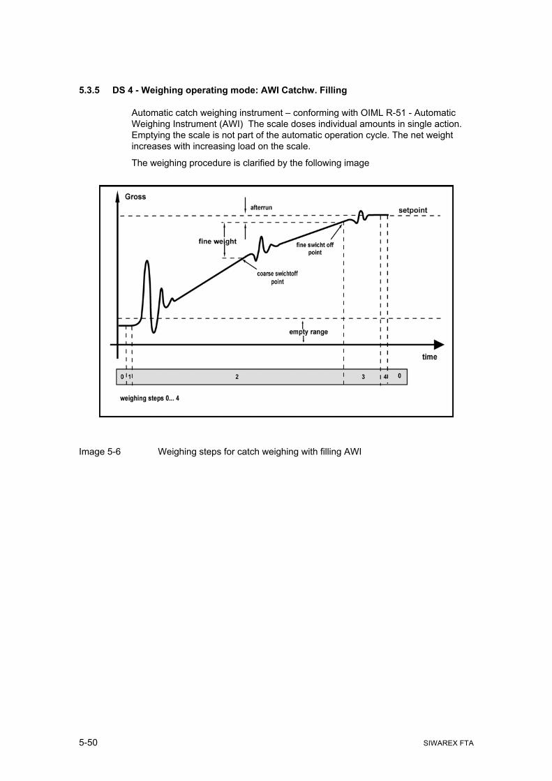
5-50 SIWAREX FTA
5.3.5 DS 4 - Weighing operating mode: AWI Catchw. Filling
Automatic catch weighing instrument – conforming with OIML R-51 - Automatic Weighing Instrument (AWI) The scale doses individual amounts in single action. Emptying the scale is not part of the automatic operation cycle. The net weight increases with increasing load on the scale.
The weighing procedure is clarified by the following image
Image 5-6 Weighing steps for catch weighing with filling AWI

Weighing Functions
SIWAREX FTA 5-51
5.3.6 DS 4 - Weighing operating mode: AWI Catchw. Emptying
Automatic catch weighing instrument – conforming with OIML R-51 - Automatic Weighing Instrument (AWI) The scale doses individual amounts in single action. Filling the scale is not part of the automatic operation cycle. The net weight decreases with increasing load on the scale.
The weighing procedure is clarified by the following image
Image 5-7 Weighing steps for catch weighing with emptying AWI

5-52 SIWAREX FTA
5.3.7 DS 4 - Weighing operating mode: AWI Check
Automatic catch weighing instrument – conforming with OIML R-51 – Automatic Weighing Instrument (AWI). The scale defines and tests the individual amounts in static single action. Putting the weighing part on the scale is done automatically, acquiring the weight is performed in static status.
The test procedure is clarified by the following image.
Image 5-8 Weighing steps for a weight recording (check) AWI

Weighing Functions
SIWAREX FTA 5-53
5.3.8 DS 4 - Weighing operating mode: AWI Totalising with Tare Re-weighing
Automatic Totalising Filling Instrument – conforming with OIML R-107 – Automatic Weighing Instrument (AWI). The scale doses out the entire amount in individual portions. Emptying the scale is part of the automatic operating cycle and is important for determining amounts.
The start of the weighing procedure sets the scale to zero. The scale container is then filled. After filling, the scale waits for stand-still 3, switches to sampling operation and tares. After emptying and achieving stand-still 2, the achieved net weight is totalised.
The weighing procedure is clarified by the following image
Image 5-9 Weighing steps for AWI Totalising

5-54 SIWAREX FTA
5.4 Weighing Steps – Standard weighing procedure
Every weighing procedure can be split into various steps.
Although weighing procedures are different for different operating modes, the individual steps can be standardised. These standardised steps enable the evaluation of the scale status at any point in time.
The user can pause the processing of a step by blocking it. The block affects the start of the step, i.e. SIWAREX FTA switches from step 2 to step for example, but if step 3 is blocked, it waits at the beginning of step 3 until the block for step 3 is deactivated.
A released block for a step cannot be used on that step again.
Activating the check stop with the "Check stop" instruction has another effect.
If a check-stop is activated before or during the processing of a step then SIWAREX FTA completes the current step and switches to "stopped" status. The "Continue" instruction starts the operation again from the current point.

Weighing Functions
SIWAREX FTA 5-55
5.4.1 Processing weighing step 0 - Wait
The scale is waiting in weighing step 0. If step 0 is blocked, no start instruction is accepted. After enabling step 0, the scale waits for the start instruction. When the start instruction is received, a check is performed to determine whether the instruction can be executed or not. If YES, it switches to step 1. If step 1 is blocked, SIWAREX FTA waits for the enable at the beginning of step 1.
Relevant Description of the Step 0 status bit status bit neutral phase
Beginning Run-time End NAWI
10 Waiting for stand-still 0 0 0 11 Standstill 1 1/0 1/0 1/0 25 Empty message 1/0 1/0 1/0
AWI 0 Weighing step 0 1 1 1 1 Weighing step 1 0 0 0 2 Weighing step 2 0 0 0 3 Weighing step 3 0 0 0 4 Weighing step 4 0 0 0 5 Weighing step 5 0 0 0 6 Weighing step 6 0 0 0 7 Weighing step 7 0 0 0 8 Post dosing active 0 0 0 9 Coarse signal 0 0 0
10 Fine signal 0 0 0 11 Timer pre-dosing 0 0 0 12 Empty signal 0 0 0 13 Weighing stopped 0 0 0 14 Halted for check stop 0 0 0 15 Check stop follows 1/0 1/0 0 16 Weighing aborted 0 0 0 17 Step blocked 1/0 0 0 18 To2 1/0 1/0 0 19 To1 1/0 1/0 0 20 Tolerance good 1/0 1/0 0 21 Tu1 1/0 1/0 0 22 Tu2 1/0 1/0 0 23 Tolerance bad 1/0 1/0 0 24 Standstill 2 1/0 1/0 1/0 25 Standstill 3 1/0 1/0 1/0 27 Block set/actual comparison 1/0 1/0 1/0 28 Continuous start active 1/0 1/0 1/0 30 Cycle end 0 0 0 31 End load operation 0 0 0
Table 5-3 Signal states in step 0
Note: 1/0 – can be 0 or 1

5-56 SIWAREX FTA
5.4.2 Description of Weighing step 1 – Taring/Zero setting
If step 1 is blocked, then no activities in step 1 are performed. After enabling step 1, the scale waits for standstill 2 (only if taring or zero setting is defined). When the standstill is achieved, the taring or the zero setting is performed. If no check stop has been activated, the SIWAREX FTA switches to step 2.
Relevant Description of the Step 1 status bit status bit Tare / Zero setting
Beginning Run-time End NAWI
10 Waiting for stand-still 1/0 1/0 0 11 Standstill 1 1/0 1/0 1 25 Empty message 1/0 1/0 1/0
AWI 0 Weighing step 0 0 0 0 1 Weighing step 1 1 1 1 2 Weighing step 2 0 0 0 3 Weighing step 3 0 0 0 4 Weighing step 4 0 0 0 5 Weighing step 5 0 0 0 6 Weighing step 6 0 0 0 7 Weighing step 7 0 0 0 P 8 Post dosing active 0 0 0 r 9 Coarse signal 0 0 0 ü
10 Fine signal 0 0 0 f 11 Timer pre-dosing 0 0 0 s 12 Empty signal 0 0 0 t 13 Weighing stopped 1/0 1/0 1/0 o 14 Halted for check stop 0 0 1/0 p 15 Check stop follows 1/0 1/0 0 16 Weighing aborted 0 1/0 1/0 m 17 Step blocked 0 0 0 ö 18 To2 0 0 0 g 19 To1 0 0 0 l 20 Tolerance good 0 0 0 i 21 Tu1 0 0 0 c 22 Tu2 0 0 0 h 23 Tolerance bad 0 0 0 24 Standstill 2 1/0 1/0 1/0 25 Standstill 3 1/0 1/0 1/0 27 Block set/actual comparison 1/0 1/0 1/0 28 Continuous start active 1/0 1/0 1/0 30 Cycle end 0 0 0 31 End load operation 0 0 0
Table 5-4 Signal states in step 1
Note: 1/0 – can be 0 or 1

Weighing Functions
SIWAREX FTA 5-57
5.4.3 Description of Weighing step 2 – Coarse/Fine
If step 2 is blocked, then no activities in step 2 are performed. After enabling step 2, the coarse and fine weighing procedures are performed When the fine signal is switched off, a check performed to determine whether a check stop requirement is active. If no check stop has been activated, the SIWAREX FTA switches to step 3.
Relevant Description of the Step 2 status bit status bit Weigh
Beginning Run-time End PS NAWI
10 Waiting for stand-still 0 0 0 11 Standstill 1 1/0 1/0 1/0 25 Empty message 1/0 0 0
AWI 0 Weighing step 0 0 0 0 1 Weighing step 1 0 0 0 2 Weighing step 2 1 1 1 3 Weighing step 3 0 0 0 4 Weighing step 4 0 0 0 5 Weighing step 5 0 0 0 6 Weighing step 6 0 0 0 7 Weighing step 7 0 0 0 P 8 Post dosing active 0 0 0 r 9 Coarse signal 1 1/0 0 ü
10 Fine signal 1 1 0 f 11 Timer pre-dosing 1/0 0 0 s 12 Empty signal 0 0 0 t 13 Weighing stopped 1/0 1/0 1/0 o 14 Halted for check stop 0 0 1/0 p 15 Check stop follows 1/0 1/0 0 16 Weighing aborted 1/0 1/0 1/0 m 17 Step blocked 1/0 0 0 ö 18 To2 0 0 0 g 19 To1 0 0 0 l 20 Tolerance good 0 0 0 i 21 Tu1 0 0 0 c 22 Tu2 0 0 0 h 23 Tolerance bad 0 0 0 24 Standstill 2 1/0 1/0 1/0 25 Standstill 3 1/0 1/0 1/0 27 Block set/actual comparison 1/0 1/0 1/0 28 Continuous start active 1/0 1/0 1/0 30 Cycle end 0 0 0 31 End load operation 0 0 0
Table 5-5 Signal states in step 2
Note: 1/0 – can be 0 or 1

5-58 SIWAREX FTA
5.4.4 Description of weighing step 3 - Post dosing
If step 3 is blocked, then no activities in step 3 are performed. After step 3 is enabled, SIWAREX FTA waits for standstill 2. If standstill 2 exists then the tolerance check is performed and post dosing occurs if necessary. If no check stop has been activated, the SIWAREX FTA switches to step 4.
Relevant Description of the Step 3 status bit status bit Trailing, Post dosing
Beginning Run-time End PSNAWI
10 Waiting for stand-still 0 0 0 11 Standstill 1 1/0 1/0 1/0 25 Empty message 0 0 0
AWI 0 Weighing step 0 0 0 0 1 Weighing step 1 0 0 0 2 Weighing step 2 0 0 0 3 Weighing step 3 1 1 1 4 Weighing step 4 0 0 0 5 Weighing step 5 0 0 0 6 Weighing step 6 0 0 0 7 Weighing step 7 0 0 0 P 8 Post dosing active 1/0 1/0 0 r 9 Coarse signal 0 0 0 ü
10 Fine signal 1/0 1/0 0 f 11 Timer pre-dosing 0 0 0 s 12 Empty signal 0 0 0 t 13 Weighing stopped 1/0 1/0 1/0 o 14 Halted for check stop 0 0 1/0 p 15 Check stop follows 1/0 1/0 0 16 Weighing aborted 1/0 1/0 1/0 m 17 Step blocked 1/0 0 0 ö 18 To2 0 0 0 g 19 To1 0 0 0 l 20 Tolerance good 0 0 0 i 21 Tu1 0 0 0 c 22 Tu2 0 0 0 h 23 Tolerance bad 0 0 0 24 Standstill 2 1/0 1/0 1/0 25 Standstill 3 1/0 1/0 1/0 27 Block set/actual comparison 1/0 1/0 1/0 28 Continuous start active 1/0 1/0 1/0 30 Cycle end 0 0 0 31 End load operation 0 0 0
Table 5-6 Signal states in step 3
Note: 1/0 – can be 0 or 1

Weighing Functions
SIWAREX FTA 5-59
5.4.5 Description of weighing step 4 - End/Intermediate check
If step 4 is blocked, then no activities in step 4 are performed. After enabling step 4, SIWAREX FTA waits for standstill 2, if a control weighing procedure has been performed, to perform the evaluation of the past weighing procedure. If no control weighing procedure is to be performed, a check is performed to determine whether a check stop is activated and if not, SIWAREX FTA switches to step 5. With the totalising scale (AWI), the switch is made to emptying weighing and taring.
Relevant Description of the Step 4 status bit status bit TOL check, Statistic data
Beginning Run-time End PSNAWI
10 Waiting for stand-still 0 0 0 11 Standstill 1 1/0 1/0 1 25 Empty message 0 0 0
AWI 0 Weighing step 0 0 0 0 1 Weighing step 1 0 0 0 2 Weighing step 2 0 0 0 3 Weighing step 3 0 0 0 4 Weighing step 4 1 1 1 5 Weighing step 5 0 0 0 6 Weighing step 6 0 0 0 7 Weighing step 7 0 0 0 P 8 Post dosing active 0 0 0 r 9 Coarse signal 0 0 0 ü
10 Fine signal 0 0 0 f 11 Timer pre-dosing 0 0 0 s 12 Empty signal 0 0 0 t 13 Weighing stopped 1/0 1/0 1/0 o 14 Halted for check stop 0 0 1/0 p 15 Check stop follows 1/0 1/0 0 16 Weighing aborted 1/0 1/0 1/0 m 17 Step blocked 1/0 0 0 ö 18 To2 0 0 1/0 g 19 To1 0 0 1/0 l 20 Tolerance good 0 0 1/0 i 21 Tu1 0 0 1/0 c 22 Tu2 0 0 1/0 h 23 Tolerance bad 0 0 1/0 24 Standstill 2 1/0 1/0 1/0 25 Standstill 3 1/0 1/0 1/0 27 Block set/actual comparison 1/0 1/0 1/0 28 Continuous start active 1/0 1/0 1/0 30 Cycle end 0 0 0 31 End load operation 0 0 0
Table 5-7 Signal states in step 4
Note: 1/0 – can be 0 or 1

5-60 SIWAREX FTA
5.4.6 Description of weighing step 5 - Empty
If step 5 is blocked, then no activities in step 5 are performed. After enabling step 5, the empty signal is output. If emptying has finished, a check is performed to determine whether a check stop requirement exists and if not, the switch to step 6 (only with totalising weighing - AWI) or to step 0.
Relevant Description of the Step 5 status bit status bit Empty
Beginning Run-time End PS NAWI
10 Waiting for stand-still 0 0 0 11 Standstill 1 1 1/0 1/0 25 Empty message 0 0 1
AWI 0 Weighing step 0 0 0 0 1 Weighing step 1 0 0 0 2 Weighing step 2 0 0 0 3 Weighing step 3 0 0 0 4 Weighing step 4 0 0 0 5 Weighing step 5 1 1 1 6 Weighing step 6 0 0 0 7 Weighing step 7 0 0 0 P 8 Post dosing active 0 0 0 r 9 Coarse signal 0 0 0 ü
10 Fine signal 0 0 0 f 11 Timer pre-dosing 0 0 0 s 12 Empty signal 1 1 0 t 13 Weighing stopped 1/0 1/0 1/0 o 14 Halted for check stop 0 0 1/0 p 15 Check stop follows 1/0 1/0 0 16 Weighing aborted 1/0 1/0 1/0 m 17 Step blocked 1/0 0 0 ö 18 To2 0 0 0 g 19 To1 0 0 0 l 20 Tolerance good 0 0 0 i 21 Tu1 0 0 0 c 22 Tu2 0 0 0 h 23 Tolerance bad 0 0 0 24 Standstill 2 1/0 1/0 1/0 25 Standstill 3 1/0 1/0 1/0 27 Block set/actual comparison 1/0 1/0 1/0 28 Continuous start active 1/0 1/0 1/0 30 Cycle end 0 0 0 31 End load operation 0 0 0
Table 5-8 Signal states in step 5
Note: 1/0 – can be 0 or 1

Weighing Functions
SIWAREX FTA 5-61
5.4.7 Description of weighing step 6 - End control AWI
If step 6 is blocked, then no activities in step 6 are performed. After step 6 is enabled, a check is performed to determine whether standstill 3 exists. If YES then the weight recording and totalling are performed. A check is then performed to determine whether a check stop requirement exists and if not, the switch to step 0 is made.
Relevant Description of the Step 6
status bit status bit Statistic data, Balance
(Tare re-weigh) Beginning Run-time End PS
NAWI 10 Waiting for stand-still 0 0 0 11 Standstill 1 1/0 1/0 1 25 Empty message 1 1 1
AWI 0 Weighing step 0 0 0 0 1 Weighing step 1 0 0 0 2 Weighing step 2 0 0 0 3 Weighing step 3 0 0 0 4 Weighing step 4 0 0 0 5 Weighing step 5 0 0 0 6 Weighing step 6 1 1 1 7 Weighing step 7 0 0 0 P 8 Post dosing active 0 0 0 r 9 Coarse signal 0 0 0 ü
10 Fine signal 0 0 0 f 11 Timer pre-dosing 0 0 0 s 12 Empty signal 0 0 0 t 13 Weighing stopped 1/0 1/0 1/0 o 14 Halted for check stop 0 0 1/0 p 15 Check stop follows 1/0 1/0 0 16 Weighing aborted m 17 Step blocked 1/0 0 0 ö 18 To2 0 0 0 g 19 To1 0 0 0 l 20 Tolerance good 0 0 0 i 21 Tu1 0 0 0 c 22 Tu2 0 0 0 h 23 Tolerance bad 0 0 0 24 Standstill 2 1/0 1/0 1/0 25 Standstill 3 1/0 1/0 1/0 27 Block set/actual comparison 1/0 1/0 1/0 28 Continuous start active 1/0 1/0 1/0 30 Cycle end 0 0 0 31 End load operation 0 0 0
Table 5-9 Signal states in step 6

5-62 SIWAREX FTA
5.4.8 Description of Weighing Step 7
Weighing step 7 is currently not utilised (Reserve).
5.4.9 DS 4 - Monitoring time for Logging
If weighing result logging is activated with an instruction or automatically, SIWAREX FTA monitors whether the procedure has been completed within the defined amount of time. If not, an error is generated.
5.4.10 DS 4 - Device for log output
Logs can be output to a connected printer or to the Micro Memory Card (MMC). The contents of the log are defined in data records DS 40 to DS 43.
5.4.11 DS 4 - Basis weight for the limit value 1
The limit values can be defined in reference to the gross weight or the net weight of the scale. This way, a very coarse dosage (net reference) or a refilling of the scale container (gross reference) can be defined for example.
5.4.12 DS 4 - Basis weight for the limit value 2
The limit values can be defined in reference to the gross weight or the net weight of the scale. This way, a very coarse dosage (net reference) or a refilling of the scale container (gross reference) can be defined for example.
5.4.13 DS 4 - Basis weight for monitoring the empty range
The limit value for monitoring the empty range can be defined in reference to the gross weight or the net weight of the scale.
5.4.14 DS 4 - Empty range
The value for the empty range is a limit value. If the weight value is below this limit value, SIWAREX FTA determines an "empty" status which is output as status information.
5.4.15 DS 4 - Switch-on weight limit value 1
Switch-on and shut-off weights can be defined separately for a limit value. This way, a minimum value monitor and a maximum value monitor can be made with a hysteresis.
Maximum value monitor is created with the following entry:
Switch-on value > shut-off value
Minimum value monitor is created with the following entry:
Switch-on value < shut-off value

Weighing Functions
SIWAREX FTA 5-63
The following image shows the functionality of limit values 1, 2, 3
Image 5-10 Defining limit value parameters
5.4.16 DS 4 - Shut-off weight limit value 1
See: Switch-on weight limit value 1
5.4.17 DS 4 - Switch-on weight limit value 2
See: Switch-on weight limit value 1
5.4.18 DS 4 - Shut-off weight limit value 2
See: Switch-on weight limit value 1
5.4.19 DS 4 - Switch-on weight limit value 3
Switch-on and shut-off weights can be defined separately for a limit value. With limit value 3, only the maximum weight monitor can be used The base weight for limit value 3 is always the gross weight.
5.4.20 DS 4 - Shut-off weight limit value 3
If the value is below the limit value, the status information is reset to "limit value 3".

5-64 SIWAREX FTA
5.4.21 DS 4 - Minimum through-put limit value 1
The through-put measurement is performed continuously. As soon as the determined through-put value falls below the limit value, it is indicated in the status display.
5.4.22 DS 4 - Minimum through-put limit value 2
The through-put measurement is performed continuously. As soon as the determined through-put value falls below the limit value, it is indicated in the status display.
5.4.23 DS 4 - Filter depth of averaging filter for through-put calculation
A separate average value filter is used for the through-put measurement. The through-put value is generated from the average value of the through-put value which SIWAREX FTA calculates with a measurement rate of 10 msec.
5.5 DS 7 Interfaces (NAWI, AWI)
The parameters that define the behaviour of the SIWAREX FT on the interfaces are defined in DS7. If an interface is not used the default values can be left alone.
o Change parameters if required.
o Send DS 7 to the scale
Name Type Address Default Range of Values / Explanation Refere
nce S7-Interface 0 Reserve BYTE DBB000 0 Source for the weight simulation
BYTE DBB001 0 0: Weight simulation inactive 1: Weight simulation value of SIMATIC 2: Weight simulation value of RS232 Other definitions not permitted.
5.5.1
Decade used for rounding the decimal places of the process values (Float weight values)
BYTE DBB002 3 0: Round to 0 decimal places 1: Round to 1 decimal place 2: Round to 2 decimal places 3: Round to 3 decimal places 4: Round to 4 decimal places 5: Round to 5 decimal places 6: Round to 6 decimal places
5.5.2
Reserve
BYTE DBB003 0 Reserve
Force service operation
BYTE DBB004 0 Bit 0 : 0: Outputs in service operation - Forced operation not possible 1: Outputs in service operation - Forced operation possible Bit 1 - 7 not used
5.5.3
Process value 1 for fast output to the SIMATIC CPU
BYTE DBB005 1 Various process values are available for selection after listing.
5.5.4
Process value 2 for fast output to the SIMATIC CPU
BYTE DBB006 2 Various process values are available for selection after listing.
5.5.5

Weighing Functions
SIWAREX FTA 5-65
Name Type Address Default Range of Values / Explanation Reference
Reserve 2
BYTE DBB007 0 Reserve 2
S7-Alarm Definition of process alarm 0
WORD DBB008 0 Value 0 - No process alarm generation Value range 1 – 0FFh Number of the technical error Value range 100h – 13Fh 100h+ 0...1Fh Bit-No. NAWI-status bit - coming 100h+ 20h...3Fh Bit-No. AWI Status flag - coming Value range 200h – 23Fh 200h+ 0...1Fh Bit-No. NAWI status bit - going 200h+ 20h...3Fh Bit-No. AWI status bit - going
5.5.6
Definition of process alarm 1
WORD DBB010 0 Value 0 - No process alarm generation Value range 1 – 0FFh Number of the technical error Value range 100h – 13Fh 100h+ 0...1Fh Bit-No. NAWI-status bit - coming 100h+ 20h...3Fh Bit-No. AWI Status bit - coming Value range 200h – 23Fh 200h+ 0...1Fh Bit-No. NAWI status bit - going 200h+ 20h...3Fh Bit-No. AWI status bit - going
5.5.6
Definition of process alarm 2
WORD DBB012 0 Value 0 - No process alarm generation Value range 1 – 0FFh Number of the technical error Value range 100h – 13Fh 100h+ 0...1Fh Bit-No. NAWI-status bit - coming 100h+ 20h...3Fh Bit-No. AWI Status bit - coming Value range 200h – 23Fh 200h+ 0...1Fh Bit-No. NAWI status bit - going 200h+ 20h...3Fh Bit-No. AWI status bit - going
5.5.6
Definition of process alarm 3
WORD DBB014 0 Value 0 - No process alarm generation Value range 1 – 0FFh Number of the technical error Value range 100h – 13Fh 100h+ 0...1Fh Bit-No. NAWI-status bit - coming 100h+ 20h...3Fh Bit-No. AWI Status bit - coming Value range 200h – 23Fh 200h+ 0...1Fh Bit-No. NAWI status bit - going 200h+ 20h...3Fh Bit-No. AWI status bit - going
5.5.6
Definition of process alarm 4
WORD DBB016 0 Value 0 - No process alarm generation Value range 1 – 0FFh Number of the technical error Value range 100h – 13Fh 100h+ 0...1Fh Bit-No. NAWI-status bit - coming 100h+ 20h...3Fh Bit-No. AWI Status bit - coming Value range 200h – 23Fh 200h+ 0...1Fh Bit-No. NAWI status bit - going
5.5.6

5-66 SIWAREX FTA
Name Type Address Default Range of Values / Explanation Reference
200h+ 20h...3Fh Bit-No. AWI status bit - going
Definition of process alarm 5
WORD DBB018 0 Value 0 - No process alarm generation Value range 1 – 0FFh Number of the technical error Value range 100h – 13Fh 100h+ 0...1Fh Bit-No. NAWI-status bit - coming 100h+ 20h...3Fh Bit-No. AWI Status bit - coming Value range 200h – 23Fh 200h+ 0...1Fh Bit-No. NAWI status bit - going 200h+ 20h...3Fh Bit-No. AWI status bit - going
5.5.6
Definition of process alarm 6
WORD DBB020 0 Value 0 - No process alarm generation Value range 1 – 0FFh Number of the technical error Value range 100h – 13Fh 100h+ 0...1Fh Bit-No. NAWI-status bit - coming 100h+ 20h...3Fh Bit-No. AWI Status bit - coming Value range 200h – 23Fh 200h+ 0...1Fh Bit-No. NAWI status bit - going 200h+ 20h...3Fh Bit-No. AWI status bit - going
5.5.6
Definition of process alarm 7
WORD DBB022 0 Value 0 - No process alarm generation Value range 1 – 0FFh Number of the technical error Value range 100h – 13Fh 100h+ 0...1Fh Bit-No. NAWI-status bit - coming 100h+ 20h...3Fh Bit-No. AWI Status bit - coming Value range 200h – 23Fh 200h+ 0...1Fh Bit-No. NAWI status bit - going 200h+ 20h...3Fh Bit-No. AWI status bit - going
5.5.6
S7 - FB Life bit monitoring time
TIME DBB024 0 0 = S7- Life bit monitor switched off 1 to n = Monitor time [msec]
5.5.7
Analogue output 0 Weight for zero point(0 or 4 mA)
REAL DBB028 0 Value output with the 0 or 4 mA 5.5.8
Reference for end value (20 mA)
REAL DBB032 0 Value output with the 20 mA. 5.5.9
Replacement value for the analogue output at OD
REAL DBB036 0 Replacement value which is output with the active OD signal if defined.
5.5.10
Source for the analogue output
BYTE DBB040 0 0 = Control signals-SIMATIC 1 = Ext. default value with DS 17 2 = Gross 3 = Net Coarse/fine default values Other definitions not permitted.
5.5.11
Current range for the analogue output
BYTE DBB041 0 Bit 0 : 0: 0 .. 20mA 1: 4 .. 20mA
5.5.12

Weighing Functions
SIWAREX FTA 5-67
Name Type Address Default Range of Values / Explanation Reference
Bit 1 – 7 unused RS232 0 RS232-printer baud rate
BYTE DBB042 3 0 = 1200 Bit/sec. 1 = 2400 Bit/sec. 2 = 4800 Bit/sec. 3 = 9600 Bit/sec. Other definitions not permitted.
5.5.13
RS232-XON/XOFF for printer RS232-RTS/CTS for printer
BYTE DBB043 1 Bit 0 : 0: XON/XOFF transmission control OFF 1: XON/XOFF transmission control ON Bit 1 : 0: CTS/RTS transmission control OFF 1: CTS/RTS transmission control ON Bit 2 : Reserved, must always be 0 Bit 3 – 7 unused
5.5.14
RS485 0 Log selection
BYTE DBB044 0 0: No device 1: SIEBERT Display S11
5.5.15
Decimal place for the remote display
BYTE DBB045 0 0 to 4 Other definitions not permitted.
5.5.16
RS485-Baudrate
BYTE DBB046 3 0 = 1200 Bit/sec. 1 = 2400 Bit/sec. 2 = 4800 Bit/sec. 3 = 9600 Bit/sec. 4 = 19200 Bit/sec. Other definitions not permitted.
5.5.17
RS485-character parity RS485-Data-Bits RS485-Stop-Bits
BYTE DBB047 0 1 0
Bit 0 : 0: Even 1: odd Bit 1 : 0: 7 data bits 1: 8 data bits Bit 2 : 0: 1 Stop Bit 1: 2 Stop Bits Bit 3 - 7 not used
5.5.18
Digital outputs 0 Definition of digital output 1
BYTE DBB048 0FFh Value range 00h – 3Fh 0...1Fh Bit-No. NAWI status flag 20h...3Fh Bit-No. AWI status flag FFh output always inactive
5.5.19
Definition of digital output 2
BYTE DBB049 0FFh Value range 00h – 3Fh 0...1Fh Bit-No. NAWI status flag 20h...3Fh Bit-No. AWI status flag FFh output always inactive
5.5.19
Definition of digital output 3
BYTE DBB050 0FFh Value range 00h – 3Fh 0...1Fh Bit-No. NAWI status flag 20h...3Fh Bit-No. AWI status flag FFh output always inactive
5.5.19
Definition of digital output 4
BYTE DBB051 0FFh Value range 00h – 3Fh 0...1Fh Bit-No. NAWI status flag 20h...3Fh Bit-No. AWI status flag
5.5.19

5-68 SIWAREX FTA
Name Type Address Default Range of Values / Explanation Reference
FFh output always inactive Definition of digital output 5
BYTE DBB052 0FFh Value range 00h – 3Fh 0...1Fh Bit-No. NAWI status flag 20h...3Fh Bit-No. AWI status flag FFh output always inactive
5.5.19
Definition of digital output 6
BYTE DBB053 0FFh Value range 00h – 3Fh 0...1Fh Bit-No. NAWI status flag 20h...3Fh Bit-No. AWI status flag FFh output always inactive
5.5.19
Definition of digital output 7
BYTE DBB054 0FFh Value range 00h – 3Fh 0...1Fh Bit-No. NAWI status flag 20h...3Fh Bit-No. AWI status flag FFh output always inactive
5.5.19
Definition of digital output 8
BYTE DBB055 0FFh Value range 00h – 3Fh 0...1Fh Bit-No. NAWI status flag 20h...3Fh Bit-No. AWI status flag FFh output always inactive
5.5.19
Level definition for digital outputs 1....8
BYTE DBB056 0 Bit 0 : DA1 -> 0 = high active: 1 = low active .... Bit 7 : DA8 -> 0 = high active: 1 = low active
5.5.20
Replacement values for digital outputs 1 .... 8 upon fault or OD signal
BYTE DBB057 0 Bit 0 : Replace value digital output 1 .... Bit 7 : Replace value digital output 8
5.5.21
Activate - Digital output replacement values for operational faults
BYTE DBB058 0 Bit 0 : 0: Replacement output upon operating error deactivated 1: Replacement output upon operating error activated Bit 1 - 7 not used
5.5.22
Reserve 3
BYTE DBB059 0 Reserve 3
Digital inputs 0 Definition of digital input 1
BYTE DBB060 0 0 = No command 1- 254 = Command code 255 = Step-on condition. (see DS -7 Scale parameter/Step control 5.15.15)
5.5.23
Definition of digital input 2 BYTE DBB061 0 0 = No command 1- 254 = Command code 255 = Step-on condition. (see DS - Scale parameter/Step control)
5.5.23
Definition of digital input 3 BYTE DBB062 0 0 = No command 1- 254 = Command code 255 = Step-on condition. (see DS - Scale parameter/Step control)
5.5.23
Definition of digital input 4 BYTE DBB063 0 0 = No command 1- 254 = Command code 255 = Step-on condition. (see DS - Scale parameter/Step control)
5.5.23
Definition of digital input 5 BYTE DBB064 0 0 = No command 1- 254 = Command code 255 = Step-on condition. (see DS - Scale parameter/Step control)
5.5.23
Definition of digital input 6 BYTE DBB065 0 0 = No command 1- 254 = Command code 255 = Step-on condition. (see DS - Scale parameter/Step control)
5.5.23
Definition of digital input 7 BYTE DBB066 0 0 = No command 1- 254 = Command code 255 = Step-on condition. (see DS - Scale
5.5.23

Weighing Functions
SIWAREX FTA 5-69
Name Type Address Default Range of Values / Explanation Reference
parameter/Step control) Level definition for digital inputs 1...7
BYTE DBB067 0 Bit 0 : Digital input 1 -> 0 = high active: 1 = low active .... Bit 6 : Digital input 7 -> 0 = high active: 1 = low active Bit 7 : not used.
5.5.24
Measurement time for pulse input
TIME DBB068 1 sec 100 to 10000 ms Other definitions not permitted.
5.5.25
Reserve 4
DWORD DBB072 0 Reserve 4
MMC Parameter 0 Log overflow Trace overflow Memory for trace
BYTE DBB076 3 Bit 0 : 0: with full memory, the logging procedures are stopped 1: with full memory, the oldest entries are overwritten Bit 1 : 0: No overwriting of trace data is possible 1: The oldest trace data is overwritten when the card is full Bit 2 : 0: Trace data is stored in RAM 1: Trace data is stored in the MMC Bit 3 - 7 not used
5.5.26
Memory segment for trace function
BYTE DBB077 50 Up to 100% but the total for trace function and log may not exceed 100%
5.5.27
Memory segment for logs
BYTE DBB078 50 Up to 100% but the total for trace function and log may not exceed 100%
5.5.28
Trace function Recording cycle
BYTE DBB079 1 1...n x 10 msec
5.5.29
80
Table 5-10 DS 7 Allocation
5.5.1 DS 7 - Source for Weight Simulation
Instead of the actual weight determination, a weight simulation can be activated for test purposes. The simulated weight values can be defined over the SIMATIC interface or the RS232 interface (SIWATOOL FTA). The weight simulation makes commissioning a scale much easier in certain situations.
5.5.2 DS 7 - Decade used for rounding the decimal places of the process values
This parameter can be used to define to how many decimal places that the (weight) process values should be rounded. This entry decouples the display of weight values which trigger the restrictions of the calibration requirements and the values that are used in the control software.

5-70 SIWAREX FTA
5.5.3 DS 7 - Force in Service Operation
After activating this function, the digital outputs can be forced independent of their parameter definitions. Force control is only possible in service operation and only with the SIMATIC interface.
! Warning
Before using this function, you must ensure that the system will not achieve any hazardous state that could be caused by forced control of digital outputs of the SIWAREX FTA.
5.5.4 DS 7 - Process value 1 for fast output to the SIMATIC CPU
The current process values can be read as data packages (data records in the SIMATIC CPU using function block FB41. Transferring a large data record can last for several CPU cycles and puts a load on system performance.
If a process value should be quickly transferred to the SIMATIC CPU immediately after its creation in the SIWAREX FTA then the peripheral interface of the SIWAREX FTA can be used. The data is read by the FB41 cyclically and provided for the user as an output variable. In automatic scale operation, the current net weight (Selection number 2) is normally important.
The selection is made from the following list.
Selection number Process value
0 NAWI-Status 1 Gross weight (Process value) 2 Net weight (Process value) 3 Tare (process value) 4 Gross-/Net weight (calibratable numeral step) 5 Gross-/Net weight (calibratable numeral step x 10) 6 Tare (calibratable) 7 Pulse counter value 8 Temperature 9 Operating error (32 bit information) 10 Unfiltered ADC value 11 Filtered ADC value (for process value) 12 Through-put / sec 30 AWI status 31 Distribution memory 1 32 Distribution memory 2 33 Total number of weightings 34 Number of control weigh procedures 35 Number of weightings over TO2 36 Number of weightings over TO1 37 Number of weightings opt. 38 Number of weightings less than TU1 39 Number of weightings less than TU2 40 Number of weightings bad 41 Reserve

Weighing Functions
SIWAREX FTA 5-71
Selection number Process value 42 Set value 43 Actual weight average value 44 Standard deviation 45 Last actual weight 46 Weighing procedures per hour 47 Performance per hour 48 Current trailing weight 49 Current fine weight 50 Filtered ADC value (for coarse-, fine signal) 51 Current load set value
Table 5-11 Selection list for process values
5.5.5 DS 7 - Process value 2 for fast output to the SIMATIC CPU
Process value 2 can be defined just the same as process value 1 (see above). In automatic scale operation, the current AWI status (Selection number 30) is normally important.
5.5.6 DS 7 - Definition of the process alarms 0, 1, 2, 3, 4, 5, 6, 7
The process alarms can be defined with this parameter. The module can generate process alarms in the SIMATIC CPU. The control program can react immediately to an event this way. Defining a process alarm is explained with the example of process alarm 0. The explanation applies for process alarms 1 to 7 as well.
If parameter value 0 is defined for process alarm 0 then no process alarms are generated.
By entering a value unequal to zero, a process alarm is allocated according to the following procedures:
Value range 1 to 255
Number of the technology message. If the defined technology error occurs then process alarm 0 is generated.
Value range 256 to 319
Number of the bit from the NAWI- or AWI status (see DS 30). If the defined status occurs then process alarm 0 is generated.
256+ 0... 31 Bit-No. NAWI Status bit - coming
288+ 0... 31 Bit-No. AWI Status bit - coming

5-72 SIWAREX FTA
Value range 512 to 575
Number of the bit from the NAWI- or AWI status (see DS 30). If the defined status goes then process alarm 0 is generated.
512+ 0... 31 Bit-No. NAWI Status bit - going
544+ 0... 31 Bit-No. AWI Status bit - going
5.5.7 DS 7 - S7-FB-Life bit Monitoring Time
By monitoring a life bit, the SIWAREX FTA can determine whether the FB is ensuring continuous communication with the SIMATIC CPU. If the FB does not respond then an operating error is output after the defined time-span has elapsed. Monitoring is active in SIMATIC_CPU RUN status.
5.5.8 DS 7 - Weight for zero point (0 or 4 mA)
A weight for the range start can be defined when defining the range parameters for the analogue output.
5.5.9 DS 7 - Weight for end value (20 mA)
A weight for the range end can be defined when defining the range parameters for the analogue output.
5.5.10 DS 7 - Replacement Value for the Analogue Output with OD
A weight can be defined for the analogue output, for which a corresponding signal is output if the OD signal (Output Disable) exists.
Normally this corresponds with the SIMATIC CPU status - STOP.
5.5.11 DS 7 - Source for the Analogue Output
The source for the analogue output can be defined with this parameter. The weight values from the defined source are output as current signals corresponding with the parameter definitions for start and end ranges.
The following sources are available:
0 - Control value form the SIMATIC (FB)
1 - Default value from the DS 17
2 - Gross weight
3 - Net weight
4 - Coarse/fine default values
5.5.12 DS 7 - Current range for the Analogue Output
The analogue output can be operated with current range 0 ... 20 mA or 4 ... 20 mA.

Weighing Functions
SIWAREX FTA 5-73
5.5.13 DS 7 - RS232 Printer baud rate
If a printer is connected to the RS232 interface, the following baud rates can be defined.
1200 Bit/sec
2400 Bit/sec
4800 Bit/sec
9600 Bit/sec
5.5.14 DS 7 - RS232- Printer transfer control
The transfer control parameters for the RS232 interfaces can be defined as follows:
XON/XOFF (for printer protocol only)
0: XON/XOFF transmission control OFF
1: XON/XOFF transmission control ON
RTS/CTS (for printer protocol only)
0: CTS/RTS transmission control OFF
1: CTS/RTS transmission control ON
5.5.15 DS 7 – Protocol selection for RS 485
The following protocols can be set for the RS485 interface
- No protocol
- Protocol for the Siebert Display S11
5.5.16 DS 7 - Decimal Place for Remote Display
If a Siebert display is to be connected to the RS485 interface then the decimal place for displaying the non-calibratable process values can be defined.
5.5.17 DS 7 – RS 485-Baudrate
The following protocols can be set for the RS485 interface:
0 = 1200 Bit/sec
1 = 2400 Bit/sec
2 = 4800 Bit/sec
3 = 9600 Bit/sec
4 = 19200 Bit/sec

5-74 SIWAREX FTA
5.5.18 DS 7 - RS485-character frame
Parity:
0: Even
1: odd
Number of data bits:
0: 7 data bits
1: 8 data bits
Number of stop bits:
0: 1 stop bit
1: 2 stop bits
5.5.19 DS 7 - Definition of the Digital Outputs 1, 2, 3, 4, 5, 6, 7, 8
The definition of the digital outputs can be defined with this parameter. Assigning a bit from the pool of status bits for the scale causes the output to be active (active can be signal level 0 or 1 - see below) if the bit is set.
When assigning a number between 0 and 63, the digital output is assigned to a status bit of the scale and when assigning a number > 63, the output remains inactive.
0... 31 Bit-No. NAWI status flag
31 + 0... 31 Bit-No. AWI status flag
Value range 64 to 255 Output always inactive
5.5.20 DS 7 - Level definitions for digital outputs 1 to 8
After assigning the definitions for digital outputs to a status bit, the signal that the output should have when it is active can be determined.
E.g. Digital output 1 (DO1) is determined with bit 0:
If bit 0 is 0 then DO1 is high active and if bit 0 is 1 then DO1 is low active,
If bit 1 is 0 then DO2 is high active and if bit 1 is 1 then DO2 is low active,
etc.
5.5.21 DS 7 - Replacement value for DO 1 to DO 8 with Interference or Output Disable
Normally, the outputs are reset with a SIMATIC CPU STOP. This behaviour corresponds with the default setting.

Weighing Functions
SIWAREX FTA 5-75
If it makes sense to set an output with a SIMATIC CPU STOP, you can define it with this parameter.
E.g. Digital output 1 (DO1) is determined with bit 0:
If bit 0 is 0 then DO1 is also 0 with OD signal.
If bit 0 is 1 then DO1 is 1 with OD signal.
The digital output 1 (DO2) is determined with bit 1:
If bit 1 is 0 then DO2 is also 0 with OD signal.
If bit 1 is 1 then DO2 is 1 with OD signal.
etc.
! Warning
If an output is to be set with the SIMATIC CPU STOP then you must ensure that it does not lead to a hazardous situation.
5.5.22 DS 7 - Replacement values for digital outputs with operational faults
Normally, the outputs are reset when there is a module group fault (operating error).. This behaviour corresponds with the default setting.
If it makes sense to set an output with a fault, you can define it with this parameter.
E.g. Digital output 1 (DO1) is determined with bit 0:
If bit 0 is 0 then DO1 is also 0 with fault.
If bit 0 is 1 then DO1 is 1 with fault.
The digital output 1 (DO2) is determined with bit 1:
If bit 1 is 0 then DO2 is also 0 with fault.
If bit 1 is 1 then DO2 is 1 with fault.
etc.
Warning
If an output is to be set with the fault (operating error) then you must ensure that it does not lead to a hazardous situation.

5-76 SIWAREX FTA
5.5.23 DS 7 - Definition of the Digital Inputs 1, 2, 3, 4, 5, 6, 7
The definition of the digital inputs can be defined with this parameter. This can be done by assigning a command or a step-on condition.
Commands:
If the signal 1 appears at the defined input then the assigned command is executed. To assign a command to an input, its command number (1 to 256) must be entered (see Command list). By entering 0, the input is assigned as unused.
Step-on condition
The step-on condition allows you to influence the weighing procedure through the control program of the SIMATIC (see chapter 8.4.8).
Entering the value 255 defines the input for the step-on conditions. In the second step, you must define which step-on condition that the input is responsible for. This is done by defining scale parameter 2 (see DS 23 – Step control ).
5.5.24 DS 7 - Level definitions for digital inputs 1 to 7
After assigning the definition for digital inputs to a command or a step-on condition, you can define which signal that the should be interpreted as active on the input.
E.g. Digital input 1 (DI1) is determined with bit 0:
If bit 0 is 0 then DI1 is high active and if bit 0 is 1 then DI1 is low active,
If bit 1 is 0 then DI2 is high active and if bit 1 is 1 then DI2 is low active,
etc.
5.5.25 DS 7 - Measurement time Pulse input
The measurement time can be defined between 1000 and 10000 Milliseconds for the counter input. Pulses are counted using the defined time intervals and are output as process values.
5.5.26 DS 7 - MMC Log Overflow, MMC Trace Overflow, Target storage for trace function
Bit 0 is used for defining how the logging should be performed in the calibratable MMC memory when the memory is full.
0: with full memory, the logging procedures are stopped
1: with full memory, the oldest entries are overwritten
Bit 1 is used for defining how the logging of trace data should continue if memory is full.
0: No overwriting of trace data is possible when MMC memory is full.
1: The oldest trace data is overwritten when MMC memory is full
The trace function is described in 5.5.29

Weighing Functions
SIWAREX FTA 5-77
Bit 2 defines which memory is used for recording the trace data.
0: Trace data is stored in RAM
1: Trace data is stored in the MMC
The trace function is described in 5.5.29
5.5.27 DS 7 - Memory segment for trace function
The MMC memory can be used for recording the trace data and for recording the calibratable scale logs.
The percentage of MMC memory that is available for the trace function is defined with this parameter.
Up to 100% is permitted in this definition but the total for trace function and calibratable log may not exceed 100%
The trace function is described in 5.5.29
5.5.28 DS 7 - Memory segment for log
The MMC memory can be used for recording the trace data and for recording the calibratable scale logs.
The percentage of MMC memory that is available for the calibratable logs is defined with this parameter.
Up to 100% is permitted in this definition but the total for trace function and calibratable log may not exceed 100%
The trace function is described in 5.5.29
5.5.29 DS 7 - Trace function recording cycle
Every n-te measurement (n x 10 msec) is recorded. When recording to RAM, n ≥ 1 is possible and when recording to MMC, n ≥ 5 is possible.
The recording can be started with the "Start Recording" 70 command and stopped with "End recording" 71 command.
A recording element has a length of 64 bytes and contains several measurement values and status bits.
Name Type Length Range of Values / Explanation Timestamp1 DATE&TIME 8 AWI status ULONG 4 status bit NAWI-Status ULONG 4 status bit Unfiltered raw value ULONG 4 Unfiltered digit value from ADC Filtered raw value LONG 4 Filtered digit value Net_Process FLOAT 4 Net weight Gross_Process FLOAT 4 Gross weight Filtered raw value 2 LONG 4 Filtered digit value from filter level 2

5-78 SIWAREX FTA
Name Type Length Range of Values / Explanation Net rough/fine shut-off FLOAT 4 Net weight for rough / fine shut-off Rough shut-off point FLOAT 4 Coarse current shut-off point Fine shut-off point FLOAT 4 Fine current shut-off point Reserved UBYTE[n] 16 Reserved 64
Table 5-12 Trace element data
The recorded values can be read with the SIWATOOL FTA and exported to MS Excel or text file.
If the trace function is defined for recording to circulating memory, it can be used for constructing a status recorder. The command for starting the recording can come from the SIMATIC control program and the command for stopping can also come from the control program, e.g. if you want to record and save the progress of a procedure.
5.6 DS 8 Date / Time (NAWI, AWI)
SIWAREX FTA has its own hardware clock. The actual date and time can be read through DS8. The date and time can be set on the module group using this data record if required.
Procedure:
o Set date and time.
o Send DS 8 to the scale
Name Type Address Default Range of Values / Explanation Refe-
rence Date / Time Date / Time
DATE_AND_TIME, DT
DBD000 01.01.01 00:00:00 000 Mo
Date&Time in SIMATIC-Format
4
Table 5-13 DS 8 Allocation
5.7 DS 9 Info on Module (NAWI, AWI)
No definitions can be made in DS9. The data record uses the information on the inner life of the module.

Weighing Functions
SIWAREX FTA 5-79
Name Type Address Default Range of Values / Explanation Reference
Info on module CRC Checksum
DWORD DBW000 0 -
Length of firmware in bytes
DWORD DBW004 0 -
Copyright
STRING [26]
DBB008 0 „Copyright Siemens AG “
Module name
STRING [10]
DBB036 SIWAREX XX
„AWI “ „NAWI“ „xxxx“ „xxxx“ „xxxx“ „xxxx“ „xxxx“
Application
STRING [4][8]
DBB048
„xxxx“
Application identification
File name
STRING [20]
DBB082 0
Version recognition Function status Data structure version Correction status
BYTE [4]
DBB104 0 Byte 0 (ASCII) before delivery approval B = Laboratory status P = Pilot R = Release S = Special status after delivery approval V = Version K = Correction status Byte 1 Function status xx (Main function changes or calibratable changes 0 ... 99) Byte 2 Version DS structure yy (indicated changes in the data structure) 0 ... 99 Byte 3 Correction status zz (small changes or error corrections) 0 ... 99
Creation date
STRING [10]
DBB108 0
Creation time
STRING [8]
DBB120 0
Boot loader version
WORD DBW130 0
Scale type
STRING [4]
DBB132 „AWI" or „NAWI“
Reserve WORD DBW138 0 Reserve 140
Table 5-14 DS 9 Allocation
5.7.1 DS 9 - Info on Module
The information on the SIWAREX FTA module are for identifying the module group at the manufacturer (e.g. for repair). This information has no influence on user operation.

5-80 SIWAREX FTA
5.8 DS 15 Tare entry (NAWI, AWI)
DS 15 is used for an external tare weight definition.
Procedure:
o Enter tare weight
o Send DS 15 to the scale
o Activate the "Accept tare entry (24)" command
Name Type Address Default Range of Values / Explanation Refe-
rence Tare entry Tare entry
REAL DBD000 0 External tare entry (Preset Tare). 5.8.1
4
Table 5-15 DS 15 Allocation
5.8.1 DS 15 - Tare Entry
DS 15 is used for an external tare weight definition. After the entry with the DS 15, the tare value is not yet activated. The transfer to the tare memory of the SIWAREX FTA is then made with the "Accept tare entry" command (see command code 24)
5.9 DS 16 Weight Simulation Entry (NAWI, AWI)
If the DS 16 has been defined as the source for the weight simulation (see DS 7 Source for the weight simulation ) then the measurement input of the SIWAREX FTA is deactivated by defining a weight value with the DS 16 and the defined value is "simulated" as a weight value.
Procedure:
o Check for whether DS 16 has been defined as the source for the weight simulation in DS 7
o Enter a value to be simulated
o Send DS 16 to the scale
Name Type Address Default Range of Values / Explanation Reference Simulation Weight simulation entry
REAL DBD000 0 Default value for weight simulation (is used instead of the gross weight e.g. for test)
5.9.1
4
Table 5-16 DS 16 Allocation
5.9.1 DS 16 - Weight simulation entry
If the DS 16 has been defined as the source for the weight simulation (see DS 7 Source for the weight simulation ) then the measurement input of the

Weighing Functions
SIWAREX FTA 5-81
SIWAREX FTA is deactivated by defining a weight value with the DS 16 and the defined value is "simulated" as a weight value. This way, system components can be tested although the scale is not yet completely constructed.
5.10 DS 17 Analogue Output Control (NAWI, AWI)
If DS17 has been defined as the source for the analogue output (see DS 7 Source for the analogue output) then sending a weight value will output a corresponding output stream on the analogue output.
Procedure:
o Check for whether DS 17 has been defined as the source for the analogue output in DS 7
o Check the parameter definition of the analogue output (see DS 7 Weight for zero point and following parameters).
o Enter value in DS 17
o Send DS 17 to the scale
Name Type Address Default Range of Values / Explanation Reference Analogue output Ext. Definition for analogue output
REAL DBD000 0 Analogue output control with a default value.
5.10.1
4
Table 5-17 DS 17 Allocation
5.10.1 DS 17 - Ext. Definition for Analogue Output
If the DS 17 has been defined as the source for controlling the analogue output (see DS 7 DS 7 - Source for the Analogue Output) then the analogue output is controlled with the defined value with a definition of a weight value on DS 17. This way, the analogue output can be set continuously from the SIMATIC control program.
5.11 DS 18 Control Display (NAWI, AWI)
A value can be defined through DS18 which is to be shown on the remote display. This way, the SIEBERT remote display can be used for displaying values that are calculated in the SIMATIC.
Procedure:
o Enter value in DS 18
o Send DS 18 to the scale

5-82 SIWAREX FTA
Name Type Address Default Range of Values / Explanation Reference Display Ext. Remote display definition
REAL DBD000 0 Remote display control with a default value.
4
Table 5-18 DS 18 Allocation
5.12 DS 20 Set Weight (AWI)
The set value for a weighing procedure that can change often in a process is passed onto the scale through DS 20. Normally, the set weight is changed when switching materials.
Procedure:
o Define the set weight
o Send DS 20 to the scale Name Type Address Default Range of Values / Explanation Reference Set weight Set weight
REAL DBD000 50 Wizzard: WRnmax*0.5
Set weight for the weighing procedure
4
Table 5-19 DS 20 Allocation
5.13 DS 21 Load set value (AWI)
In loading operation, the overall amount of the material to be loaded is defined. The scale performs the individual weighing procedure according to the defined set weight for an individual weighing procedure In loading operation , the set weight is defined with zero. Procedure:
o Define the set weight
o Send DS 20 to the scale Name Type Address Default Range of Values / Explanation Reference Load set value Load set value
REAL DBD000 1000 Wizzard: WBnmax*10
Total set weight for filling operation
4
Table 5-20 DS 21 Allocation

Weighing Functions
SIWAREX FTA 5-83
5.14 DS 22 Scale Parameter 1 (AWI)
The weighing parameters that change more often in the process are defined in DS 22. Normally, these parameters are changed for switching materials and are then sent to the SIWAREX FTA again.
Procedure:
o Define all parameters according to the material properties
o Send DS 22 to the scale
o If required, check parameters using tests
Name Type Address Default Range of Values / Explanation Reference Scale parameter 1 Maximum weighing time
Time DBD000 0 0: deactivated, Definition in msec. 5.14.1
Trailing weight
REAL DBD004 1 Wizzard WBnmax * 0,01
Trailing amount after switching fine signal off 5.14.2
Fine weight
REAL DBD008 20 Wizzard: WBnmax*0,2
Amount for dosing during the fine signal 5.14.3
Shut-off correction value
REAL DBD012 0 +/- value for moving the shut-off point for the fine signal
5.14.4
Timer pre-dosing
TIME DBD016 0 0: deactivated > 0: Pre-dosing time in msec
5.14.5
TO1
REAL DBD020 0,2 Wizzard: WBnmax * 0,002
Upper tolerance limit TO1 (entry of the permitted positive deviation from set weight)
5.14.6
TU1
REAL DBD024 0,2 Wizzard: WBnmax * 0,002
Lower tolerance limit TU1 (entry of the permitted negative deviation from set weight)
5.14.6
TO2
REAL DBB028 0,5 Wizzard: WBnmax * 0,005
Entry of the upper tolerance limit 2, must be greater than TO1.
5.14.6
TU2
REAL DBB032 0,5 Wizzard: WBnmax * 0,005
Entry of the lower tolerance limit 2, must be greater than TU1.
5.14.6
36
Table 5-21 DS 20 Allocation
5.14.1 DS 22 - Maximum Weighing Time
The weighing time is started with the start of a weighing procedure. After the defined time has elapsed, a test is performed to determine whether the weighing procedure will take longer. If yes then a technology error "Weighing time exceeded" is generated. The weighing procedure is not influenced by the technology error message.

5-84 SIWAREX FTA
5.14.2 DS 22 - Trailing Weight
The trailing weight should correspond with the amount to add to the amount of the dosage from the coarse- and fine-signal after switching the fine signal off. This means, the fine shut-off point can be calculated as follows:
Fine shut-off point = Set value – trailing weight
The proportional controllers can offset the fine shut-off point by determining the new trailing weight.
5.14.3 DS 22 - Fine Weight
The fine weight entry should correspond with the material amount that was dosed during the fine signal (after switching off the coarse signal until switching off the fine signal). The defined value should be measured so that the material flow can be stabilised by the time that the fine signal is switched off. This means, the coarse shut-off point can be calculated as follows:
coarse shut-off point = Set value – Fine weight – Trailing weight
The proportional controllers can offset the rough shut-off point by determining the new trailing weight.
5.14.4 DS 22 - Shut-off correction value
The shut-off correction value for the fine signal changes the fine shut-off point by the defined entry. The resulting fine shut-off point offset can be used to deliberately achieve an over-dosage or under-dosage. This can be used to compensate for interfering forces such as pressure, vacuum, etc., occurring with the dosage.
5.14.5 DS 22 - Timer pre-dosing
If an output has been defined for the pre-dosing (see DS 7 - Definition of the Digital Outputs 1, 2, 3, 4, 5, 6, 7, 8) then the time that is started with the weighing procedure start and which controls a coarse pre-dosing that depends on time can be defined with this parameter. This can be used if another dosing step (coarse 1, coarse 2) is required in addition to coarse and fine steps for example.
5.14.6 DS 22 –Tolerance TO1, Tolerance TU1, Tolerance TO2, Tolerance TU2
4 values can be defined for the tolerance evaluation. Based on this value, the results of the automatic operation are tested with reference to the set value. The values are defined so that TO2 > TO1 and TU2 > TU1.
This way, 2 tolerance bands are defined around the set value.

Weighing Functions
SIWAREX FTA 5-85
The tolerance evaluation is performed after switching the fine signal off if the scale stabilises and stands still.
The following image shows the progress of the tolerance evaluation over time.
Image 5-11 Tolerance evaluation progress by time with TU1 status
The result of the tolerance evaluation is output based on the defined tolerance values. All information on the weighing result is distributed with 6 status bits.
TO1 – upper tolerance value 1
TO2 – upper tolerance value 2
TU1 – lower tolerance value 1
TU2 – lower tolerance value 2
Good - within tolerance band from TU1 to TO1
Off - outside of tolerance TU2 to TO2 (can be used for sorting the weighing material)

5-86 SIWAREX FTA
Table 5-22 Tolerance information evaluation
5.15 DS 23 Scale parameter 2 (AWI)
Weighing parameters are held in DS23. These are normally typical to the scale and do not depend heavily on the changing material properties within a limited extent. Procedure:
o Adjust all parameters corresponding to their purpose
o Send DS 23 to the scale
o If required, check parameters using tests
Name Type Address Default Range of Values / Explanation ReferenceScale parameter 2 0 Text selection for automatic logging
BYTE DBB000 1 0: No autom. logging after the weighing procedure 1: autom. logging with text 1 2: autom. logging with text 2 3: autom. logging with text 3 4: autom. logging with text 4 Other definitions not permitted.
Reserve 1
BYTE DBB001 0 Reserve 1
Reserve 2
WORD DBB002 0 Reserve 2
Max. single set weight REAL DBD004 90 Wizzard: WBnmax *
Maximum set weight for a single 5.15.2
Inhibition time coarse
TIME DBD008 500 0: deactivated After switching the coarse signal on, no weight evaluation is performed for the defined amount of time (msec)!
Inhibition time fine
TIME DBD012 500 0: deactivated After switching the coarse signal off, no weight evaluation is performed for the defined amount of time (msec)!
5.15.4
Inhibition time Set-Act-comparison
TIME DBD016 0 After the command for starting the inhibition time, the actual weight is not monitored during the weighing procedure for the defined amount of time.
5.15.5
Default value for analogue output with coarse
BYTE DBB020 60 Analogue output value if coarse signal active (in %)
Default value for analogue output with fine
BYTE DBB021 40 Analogue output value if fine signal active (in %) 5.15.7
Dosing filter type
BYTE DBB022 0 Filter type for dosage control 0: critically damped 1: Bessel-Filter
5.15.8
Status output condition TO2 TO1 Good TU1 TU2 Off Net weight from TU1 to TO1 0 0 1 0 0 0 Net weight above TO1 to TO2 0 1 0 0 0 0 Net weight above TO2 1 0 0 0 0 1 Net weight from TU2 to under TU1 0 0 0 1 0 0 Net weight under TU2 0 0 0 0 1 1

Weighing Functions
SIWAREX FTA 5-87
Name Type Address Default Range of Values / Explanation Reference2: Butterworth Filter Other definitions not permitted.
Dosing filter limit frequency
BYTE DBB023 2 0: No filter 1: fg = 20Hz 2: fg = 10Hz 3: fg = 5Hz 4: fg = 2Hz 5: fg = 1Hz 6: fg = 0,5Hz 7: fg = 0,2Hz 8: fg = 0.1Hz 9: fg = 0´.05Hz Other definitions not permitted.
5.15.9
Tare / Zero setting 0 Tare / Zero setting mode
BYTE DBB024 0 0: No taring, no zero setting at weighing start 1: Zero setting 2: Tare 3: Taring with average value 4: Taring using external entry tare Other definitions not permitted.
5.15.10
Tare / Zero setting cycle
BYTE DBB025 0 0: Every weighing is nullified or tared 1: Tipping is not nullified or tared 2...99: 2…99 tippings not nullified or tared Other definitions not permitted.
5.15.11
Reserve 3
WORD DBB026 0 Reserve 3
Tare min. weight
REAL DBB028 0 Taring or ext. tare entries are only executed if gross > tare minimum weight 0: No monitoring of the tare minimum weight
5.15.12
Tare max. weight
REAL DBB032 0 Tarring or ext. Tare entries are only executed if gross < tare maximum weight 0: No monitoring of the tare maximum weight
5.15.13
Cycle time for zero setting
TIME DBB036 300000 msec
If 0, then no time controlled zero setting Unequal 0: Time between two zero settings Note: Zero setting / taring is performed after 15min at the latest with weighing operating mode AWI and country code "OIML"
5.15.14
Step control / check stop Step control through digital input 1
BYTE DBB040 0 Instead of defined command codes for the digital inputs, step-on conditions can be influenced through the inputs for dosing control (prerequisite in DS interface parameters is identification 0xFF). 0: Weighing waits at step 0 if DI1 is active; 1: Weighing waits at step 1 if DI1 is active 2: Weighing waits at step 2 if DI1 is active ... 7: Weighing waits at step 7 if DI1 is active Other definitions not permitted.
5.15.15
Step control through digital input 2
BYTE DBB041 0 Instead of defined command codes for the digital inputs, step-on conditions can be influenced through the inputs for weighing control (prerequisite in DS interface parameters is identification 0xFF). 0: Weighing waits at step 0 if DI2 is active; 1: Weighing waits at step 1 if DI2 is active 2: Weighing waits at step 2 if DI2 is active ... 7: Weighing waits at step 7 if DI2 is active Other definitions not permitted.
5.15.15
Step control through digital input 3
BYTE DBB042 0 Instead of defined command codes for the digital inputs, step-on conditions can be influenced through the inputs for weighing control (prerequisite in DS interface parameters is identification 0xFF).
5.15.15

5-88 SIWAREX FTA
Name Type Address Default Range of Values / Explanation Reference 0: Weighing waits at step 0 if DI3 is active; 1: Weighing waits at step 1 if DI3 is active 2: Weighing waits at step 2 if DI3 is active ... 7: Weighing waits at step 7 if DI3 is active Other definitions not permitted.
Step control through digital input 4
BYTE DBB043 0 Instead of defined command codes for the digital inputs, step-on conditions can be influenced through the inputs for weighing control (prerequisite in DS interface parameters is identification 0xFF). 0: Weighing waits at step 0 if DI4 is active; 1: Weighing waits at step 1 if DI4 is active 2: Weighing waits at step 2 if DI4 is active ... 7: Weighing waits at step 7 if DI4 is active Other definitions not permitted.
5.15.15
Step control through digital input 5
BYTE DBB044 0 Instead of defined command codes for the digital inputs, step-on conditions can be influenced through the inputs for weighing control (prerequisite in DS interface parameters is identification 0xFF). 0: Weighing waits at step 0 if DI5 is active; 1: Weighing waits at step 1 if DI5 is active 2: Weighing waits at step 2 if DI5 is active ... 7: Weighing waits at step 7 if DI5 is active Other definitions not permitted.
5.15.15
Step control through digital input 6
BYTE DBB045 0 Instead of defined command codes for the digital inputs, step-on conditions can be influenced through the inputs for weighing control (prerequisite in DS interface parameters is identification 0xFF). 0: Weighing waits at step 0 if DI6 is active; 1: Weighing waits at step 1 if DI6 is active 2: Weighing waits at step 2 if DI6 is active ... 7: Weighing waits at step 7 if DI6 is active Other definitions not permitted.
5.15.15
Step control through digital input 7
BYTE DBB046 0 Instead of defined command codes for the digital inputs, step-on conditions can be influenced through the inputs for weighing control (prerequisite in DS interface parameters is identification 0xFF). 0: Weighing waits at step 0 if DI7 is active; 1: Weighing waits at step 1 if DI7 is active 2: Weighing waits at step 2 if DI7 is active ... 7: Weighing waits at step 7 if DI7 is active Other definitions not permitted.
5.15.15
Reserve 4
BYTE DBB047 0 Reserve 4
Monitoring time step control
TIME DBB048 0 0: No monitoring >0 Time definition for the monitoring If no further stepping to the next weighing step is performed within the defined time then the "Step-on Timeout" technology error is generated.
5.15.16
Definition check stop
BYTE DBB052 0 Bit 0 : No check stop Bit 1 : Weighing goes to check stop after step 1 Bit 2 : Weighing goes to check stop after step 2 ... Bit 7 : Weighing goes to check stop after step 7 Other definitions not permitted.
5.15.17
Reserve 5
BYTE DBB053 0 Reserve 5
Post dosing tolerance

Weighing Functions
SIWAREX FTA 5-89
Name Type Address Default Range of Values / Explanation Referencecheck Automatic dosing Dosing method Stop if more than TO1 Stop if more than TO2
BYTE DBB054 0 Bit 0 : 0: No automatic post dosing 1: autom. post dosing for Tol-1 deviation Bit 1 : 0: post dosing with continuous fine signal 1: post dosing pulse mode Bit 2 : 0: Weighing procedures not stopped because of tolerance errors 1: Weighing stopped because of tolerance error (weight above TO1) Bit 3 : 0: autom. Weighing procedures not stopped because of tolerance errors 1: Weighing stopped because of tolerance error (weight above TO2) Bits 4 to 7 not used
5.15.18 5.15.19 5.15.20 5.15.21
Control pause
BYTE DBB055 0 0: All weighing procedures are checked for tolerance deviations 1: A weighing procedure is not checked for tolerance deviations 2...98: 2...98 weighing procedures are not checked for tolerance deviations, 99 no check Other definitions not permitted.
5.15.22
Pulse duration for pulse dosing
TIME DBD056 1000 msec Pulse duration of fine signal (in msec) 5.15.23
Controller Controller behaviour at scale fault
BYTE DBB060 0 Bit 0 : 0: Reset controller for technology error (weighing fault) 1: Limit controller to max. Access Bits 1 to 7 not used
Selection for type of controller
BYTE DBB061 0 0: No control for switching off the rough-/fine-signal 1: Proportional controller without fine signal time controller 2: Proportional controller with fine-signal time controller 3: Fine signal time controller without proportional controller Other definitions not permitted.
5.15.25
Control factor Proportional controller
BYTE DBB062 30 [0…100 %] Other definitions not permitted.
5.15.26
Reserve 5a BYTE 1 0 Reserve 5a Maximum one-time control access
REAL DBD064 1 Limitation for maximum one-time control access of proportional controller
5.15.27
Controller optimum Plus
REAL DBD068 0 0…WRmax
Controller optimum Minus
REAL DBD072 0 0…WRmax 5.15.29
Set value for fine time
TIME DBD076 3000 Definition of set time for the fine signal-time controller
5.15.30
Control factor fine time controller
BYTE DBB080 20 0...100 [%] Other definitions not permitted.
5.15.31
Reserve 6 BYTE DBB081 0 Reserve 6
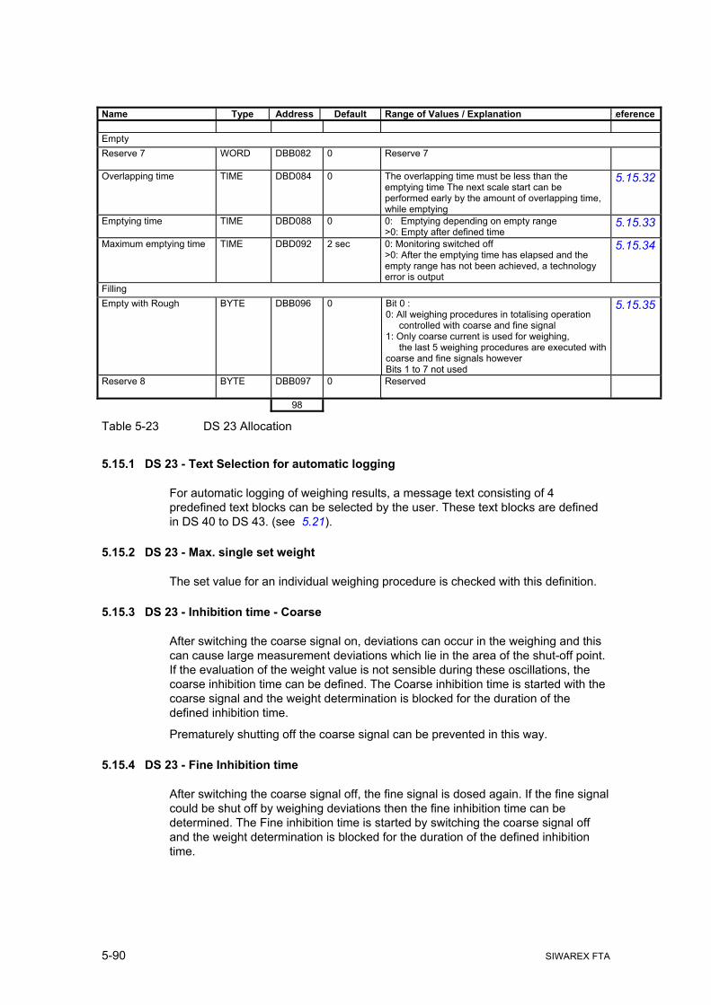
5-90 SIWAREX FTA
Name Type Address Default Range of Values / Explanation Reference Empty Reserve 7
WORD DBB082 0 Reserve 7
Overlapping time
TIME DBD084 0 The overlapping time must be less than the emptying time The next scale start can be performed early by the amount of overlapping time, while emptying
5.15.32
Emptying time
TIME DBD088 0 0: Emptying depending on empty range >0: Empty after defined time
5.15.33
Maximum emptying time
TIME DBD092 2 sec 0: Monitoring switched off >0: After the emptying time has elapsed and the empty range has not been achieved, a technology error is output
5.15.34
Filling Empty with Rough
BYTE DBB096 0 Bit 0 : 0: All weighing procedures in totalising operation controlled with coarse and fine signal 1: Only coarse current is used for weighing, the last 5 weighing procedures are executed with coarse and fine signals however Bits 1 to 7 not used
5.15.35
Reserve 8
BYTE DBB097 0 Reserved
98
Table 5-23 DS 23 Allocation
5.15.1 DS 23 - Text Selection for automatic logging
For automatic logging of weighing results, a message text consisting of 4 predefined text blocks can be selected by the user. These text blocks are defined in DS 40 to DS 43. (see 5.21).
5.15.2 DS 23 - Max. single set weight
The set value for an individual weighing procedure is checked with this definition.
5.15.3 DS 23 - Inhibition time - Coarse
After switching the coarse signal on, deviations can occur in the weighing and this can cause large measurement deviations which lie in the area of the shut-off point. If the evaluation of the weight value is not sensible during these oscillations, the coarse inhibition time can be defined. The Coarse inhibition time is started with the coarse signal and the weight determination is blocked for the duration of the defined inhibition time.
Prematurely shutting off the coarse signal can be prevented in this way.
5.15.4 DS 23 - Fine Inhibition time
After switching the coarse signal off, the fine signal is dosed again. If the fine signal could be shut off by weighing deviations then the fine inhibition time can be determined. The Fine inhibition time is started by switching the coarse signal off and the weight determination is blocked for the duration of the defined inhibition time.

Weighing Functions
SIWAREX FTA 5-91
5.15.5 DS 23 - Inhibition time Set-Act comparison
After the command that starts the inhibition time, the actual weight will not be monitored for the defined amount of time.
Deactivating the function is done when the defined inhibition time has elapsed or with a command. This function is advantageous when using discharge aids.
5.15.6 DS 23 - Default value for analogue output with course
If the output of a fixed value has been defined during the coarse-/fine-signal (see DS 7 Source for the analogue output ) then the output current during the coarse signal is defined with the parameter (1... 100%).
5.15.7 DS 23 - Default value for analogue output with fine
If the output of a fixed value has been defined during the coarse-/fine-signal (see DS 7 Source for the analogue output ) then the output current during the fine signal is defined with the parameter (1... 100%).
5.15.8 DS 23 - Filter type for dosing
A separate low-pass filter is used exclusively for the precise control of switching the coarse and fine signal off. Normally, these settings should correspond with the settings for the filter in DS3.
The filter type can be defined with this parameter.
5.15.9 DS 23 - Limit Frequency Filter for dosing
A separate low-pass filter is used exclusively for the precise control of switching the coarse and fine signal off. Normally, these settings should correspond with the settings for the filter in DS3.
The limit frequency of the low-pass filter can be defined with this parameter.
5.15.10 DS 23 - Tare-/Zero setting mode
This parameter defines whether the scale starts with:
o neither taring nor zero setting,
o zero setting,
o taring,
o taring with a tare average value (from 10 taring procedures),
o or the external tare definition (see DS 15 - Tare Entry ).

5-92 SIWAREX FTA
5.15.11 DS 23 - Tare / Zero setting cycle
The entry defined how often the scale must perform a taring or zero setting:
o 0: Every weighing is nullified or tared
o 1: Tipping is not nullified or tared
o 2 to 99: 2 to 99 tippings not nullified or tared
Note
In calibrating applications with the SIWAREX FTA as an automatic weighing instrument for emptying operation, a taring or zero setting is performed automatically after the defined time of 15 minutes has elapsed (see DS 3 Regulations ).
5.15.12 DS 23 - Tare minimum weight
Along with the parameter tare max. weight, a weighing range can be defined within which taring is permitted.
5.15.13 DS 23 - Tare max. weight
Along with the parameter tare min. weight, a weighing range can be defined within which taring is permitted.
5.15.14 DS 23 - Time period for zero setting
With a definition of "0", the time controlled zero setting for the scale is not performed. A definition unequal to "0" means that the scale performs a zero setting automatically after this time has elapsed.
Note
The time controlled zero setting is not performed in the scale cycle.
In calibrating applications with the SIWAREX FTA as an automatic weighing instrument for emptying operation, a taring or zero setting is performed automatically after the defined time of 15 minutes has elapsed (see DS 3 Regulations ).

Weighing Functions
SIWAREX FTA 5-93
5.15.15 DS 23 - Step control through digital input 1, 2, 3, 4, 5, 6, 7
Instead of definable command codes for the digital inputs, step-on conditions can be controlled by the inputs for scale control (in DS 7, designation 0xFF is defined with the definition of the digital inputs, see Definition of digital input 1).
The following applies for digital input DI1:
0: Weighing waits at step 0 if DI1 is active;
1: Weighing waits at step 1 if DI1 is active
2: Weighing waits at step 2 if DI1 is active
...
7: Weighing waits at step 7 if DI1 is active
The digital inputs 2 to 7 are defined similar to this.
5.15.16 DS 23 - Monitor time step control
This definition enables the monitoring of the duration of a process step:
- 0: No monitoring
- >0 Time definition for the monitoring
If no further stepping to the next process step is performed within the defined time then the "Step-on Timeout" technology error is generated.
5.15.17 DS 23 - Definition check stop points
A check stop can be effective at the end of a step. This parameter can be used to define the check stop points. After activating the command "Check stop" (see command 107), SIWAREX FTA stops at the next point of the process. With the "Continue" command (see command 103), the automatic processing can continue.
5.15.18 DS 23 - Automatic post dosing
After switching off the fine signal, the SIWAREX FTA waits for the stand-still. Next is the tolerance check. This parameter is for defining whether dosing should be done automatically if the weight is less than the set value minus the lower tolerance TU1:
0: No automatic post dosing
1: Automatic post dosing when below TU1 deviation
5.15.19 DS 23 - Post dosing type
The type of automatic post dosing is defined with this parameter:
0: post dosing with continuous fine signal
1: post dosing pulse mode

5-94 SIWAREX FTA
5.15.20 DS 23 - Stop on TO1
This parameter defines whether the automatic processing should stop if the current net weight increases to more than the set value plus TO1.
0: Weighing procedures not stopped for tolerance error
1: Weighing stopped because of tolerance error (weight above TO1)
5.15.21 DS 23 - Stop on TO2
This parameter defines whether the automatic processing should stop if the current net weight increases to more than the set value plus TO2.
0: Weighing procedures not stopped for tolerance error
1: Weighing stopped because of tolerance error (weight above TO2)
5.15.22 DS 23 - Control pauses
To increase the material throughput, it may be sensible in certain filling systems to avoid checking every weighing procedure (applies only in SWA operating mode).
This parameter defines how often that the tolerance check should be done.
0: Tolerance deviation checked every weighing procedure.
1: A weighing procedure is not checked for tolerance deviations
2 to 98: 2 to 98 weighing procedures are not checked for tolerance deviations
99: No tolerance deviation checking
5.15.23 DS 23 - Pulse duration in pulse dosing
If the automatic post dosing in pulse dosing operation is defined, this parameter can be used to define the fine signal pulse duration. The pause time is then made up of the minimum time value at stand-still 2 and from the waiting for meeting conditions for stand-still 2.

Weighing Functions
SIWAREX FTA 5-95
Image 5-12 Automatic post dosing with tolerance TU1
5.15.24 DS 23 - Controller behaviour with dosage fault
If used with parameters Fine weight, Inhibition times, Trailing
If a technology error occurs during the weighing procedure this parameter can define how the proportional controller or the fine-time-controller should act – limiting the control in this case only or reset the parameter to the original value.
5.15.25 DS 23 - Selection for type of controller
Two controllers are integrated in SIWAREX FTA: A proportional controller for correcting the definition for the trailing weight and a fine signal time controller for ensuring the defined duration for the fine signal.
It is also possible to run both controllers at the same time.
5.15.26 DS 23 - Control factor Proportional controller
The proportional controller sets the definition for the trailing weight to adjust it to the actual trailing amounts.
The determined deviation of the weighing net value from the weighing set value is multiplied with the defined control factor (Control factor Proportional controller) and is used for the next filling as a correction set amount.

5-96 SIWAREX FTA
The trailing weight for the following weighing procedures is calculated according to the following formula:
G(n+1) = Gn + (S – A)n • C/100%
G(n+1) Trailing weight for the next weighing procedure
Gn Trailing weight for the last weighing procedure
S Set weight
A Net weight for the last weighing procedure
C Control factor for proportional controller in %
n Current weighing procedure
n+1 Following weighing
5.15.27 DS 23 - Maximum one-time correction with the proportional controller
The proportional controller sets the definition for the trailing weight to adjust it to the actual trailing amounts. By defining the maximum correction value, the one-time change can be limited by the controller. This limits runaway values to the maximum correction value.
The trailing weight is modified by the value
(S – A)n • C/100%
If the calculation of a larger value as the maximum correction value, only the maximum correction value is used for the correction of the trailing weight. Therefore, the formula for calculating the trailing weight is now:
G(n+1) = Gn + maximum correction value
5.15.28 DS 23 - Controller Optimum Plus
By defining the Controller Optimum Plus parameter, a weight tolerance is defined above the set weight within which the proportional controller should not control to a finer degree.
5.15.29 DS 23 - Controller Optimum Minus
By defining the Controller Optimum Plus parameter, a weight tolerance is defined below the set weight within which the proportional controller should not control to a finer degree.
5.15.30 DS 23 - Set value for fine time
If the fine time controller has been activated (see controller type selection 5.15.25) then the desired duration can be set for the fine signal.
The fine time controller optimises the fine signal duration by setting the fine weight and therefore the rough current shut-off point. The shut-off point is set so that the

Weighing Functions
SIWAREX FTA 5-97
actual duration of the fine signal in a controlled status corresponds with the defined value. The control deviation is defined after the end of the fine dosing:
tDiff = tSet - tAct
tDiff = Control difference (s)
tSet = Fine set time (s) (=Default value)
tAct = Fine actual time (s)
The set value for the fine time is defined by the user depending on the material properties.
5.15.31 DS 23 - Control factor fine time controller
The controller sets the rough shut-off point by changing the fine weight.
Fn+1 = Fn + (K * DFine * tDiff)
Fn = Fine weight for current weighing procedure
Fn+1 = Fine weight for next weighing procedure
K = Control factor fine time controller
DFine = Throughput to shut-off time point for the
fine signal
tDiff = Control difference (deviation)
5.15.32 DS 23 - Overlapping time
The overlapping time can be used in combination with emptying over time.
The next start can be advanced by the overlapping time although the emptying procedure is not yet ended.
Note
For emptying over time, you should take measures to ensure that the scale is actually empty after the emptying time has elapsed.
5.15.33 DS 23 - Emptying time
Emptying over time is activated with an entry unequal to 0. The empty signal is activated for the defined time. When this time period has elapsed, the empty signal is reset.
The emptying procedure is ended when the empty range is achieved with a definition of =0.

5-98 SIWAREX FTA
5.15.34 DS 23 - Maximum empty time
If emptying is not ended after a duration of time and is performed after achieving the empty range instead, a monitoring time can be defined here. The monitoring time is started with the empty signal. If the empty range has not be been achieved when this time has elapsed, a technology message is output.
5.15.35 DS 23 - Filling with coarse
For filling operation, you can define whether filling should be completed with coarse and fine signals or only with coarse signals.
When filling with "Coarse signal only", the last 5 weighing procedures are run with coarse and fine signals.
5.16 DS 30 Process values 1 (NAWI, AWI)
The current states and data in the scale can be monitored using process values 1 and 2.
Observing the selected data is very helpful in test operation for optimising parameters. In addition, if the SIWAREX FTA is controlled by the SIMATIC CPU then the status can also be observed.
Name Type Address Range of Values / Explanation Referen
ce NAWI status bits
DWORD DBD000 32 status displays for NAWI
AWI status bits
DWORD DBD004 32 status displays for AWI
Gross process value
REAL DBD008 Current gross weight (Process value)
Net process value
REAL DBD012 Current net weight (Process value)
Tare process value
REAL DBD016 Current tare weight (Process value)
G/N weight
REAL DBD020 Current weight (numeral step from DS3)
G/N weight_x10
REAL DBD024 Current weight (numeral step from DS3)
Tare
REAL DBD028 Current tare weight (numeral step from DS3)
Last net weight REAL DBD032 Net weight of the last monitored weighing procedure (numeral step from DS3)
Pulse counter value
DWORD DBD036 Current pulse counter value
Distribution memory 1
REAL DOUBLE
DBD040 Current distribution memory 1 value. Format in STEP7 cannot be read (numeral step from DS3)
Distribution memory 2 REAL DBD048 Current distribution memory 2 value (numeral step from DS3)
52
Table 5-24 DS 30 Allocation

Weighing Functions
SIWAREX FTA 5-99
5.16.1 DS 30 - NAWI-Status bits
Bit No. Name Range of Values / Explanation Reference
0 WR1 Weight within weighing range 1 1 WR2 Weight within weighing range 2 2 WR3 Weight within weighing range 3 3 Limit 1 Limit value 1 activated 4 Limit 2 Limit value 2 activated 5 Limit 3 Limit value 3 activated 6 Tared (NET) Set if the scale is tared 7 Preset Tare Set if the scale was tared with tare input 8 Max+9e Set if maximum load is exceeded by 9 e 9 ¼d-Zero Set if the weight does not exceed ¼ d
10 Waiting for stand-still Set if the scale waits for a stand-still after the weighing start. 11 Standstill 1 Stand-still 1 exists 12 Scale adjusted Set if the scale is adjusted (calibrated) 13 Error on DI Set if a command could not be executed on a digital input 14 Simulation active Set if the weight simulation has been activated 15 Service operation active Set if service operation has been activated 16 Printing log The log is being printed. 17 RS232-Print not possible The log cannot be printed. 18 MMC inserted The MMC is in position 19 MMC ready The MMC is formatted and ready for recording 20 MMC-trace ready The MMC is ready for the trace function 21 MMC-log ready The MMC is ready for logging 22 Trace active The trace function is activated 23 Min. through-put 1 overshot Through-put monitor 1 activated 24 Min. through-put 2 overshot Through-put monitor 2 activated 25 Empty message Scale in empty range 26 Calibration data protection The switch for protecting the calibration data is switched on 27 28 29 30 31 Operating error At least one operating error (fault) exists
Table 5-25 DS 30 - NAWI status bits
5.16.2 DS 30 - AWI status flags
Bit No. Name Range of Values / Explanation Reference
0
1 2 3 4 5 6 7
Weighing steps Current weighing control step 0 to 7
8 Post dosing active Post dosing is active 9 Course signal The coarse signal is switched on
10 fine signal The fine signal is switched on 11 Timer pre-dosing The timer for pre-dosing is active 12 Empty signal The empty signal is switched on 13 Weighing stopped The weighing cycle has been stopped 14 Weighing stopped because
of check stop The weighing cycle has been stopped because of the check stop command

5-100 SIWAREX FTA
Bit No. Name Range of Values / Explanation Reference15 Check stop follows The weighing cycle will be stopped by a check stop
(is set with the check stop command and reset if the check stop is achieved)
16 Last weighing procedure aborted
Last weighing procedure aborted with "Residual weighing" or "Reset weighing control".
17 Weighing blocked Set if the step-on to the next step in the weighing cycle is blocked because of a missing step enable.
18 TO2 Net weight above the TO2 limit 19 TO1 Net weight above TO1 20 Good Net weight in tolerance TU1 to TO1 21 TU1 Net weight under TU1 but over TU2 22 TU2 Net weight under TU2 23 TOL bad Net weight under TU2 or over TO2 24 Standstill 2 Stand-still 2 exists 25 Standstill 3 Stand-still 3 exists 26 Reserve 1 27 Block set/actual comparison
active The set/actual comparison is blocked, the weighing procedure is running without a weight evaluation!
28 Continuous start active Continuous start for the cycle sequence is activated 29 Reserve 2 30 Cycle end The weighing cycle has ended 31 Charge end The emptying operation has ended
Table 5-26 DS 30 - AWI status flags
5.16.3 DS 30 - Gross process value
The momentary gross weight value
5.16.4 DS 30 - Net process value
The momentary net weight value
5.16.5 DS 30 - Tare process value
The momentary tare weight value
5.16.6 DS 30 - B/N weight
The momentary weight value which will be used for the main display.
5.16.7 DS 30 - B/N weight_x10
The momentary weight value in increased resolution which will be used for the main display.
5.16.8 DS 30 - Tare
The momentary tare weight value (numeral step from DS3).
5.16.9 DS 30 - Net weight
The net weight of the last weighing procedure with tolerance control (numeral step from DS3).

Weighing Functions
SIWAREX FTA 5-101
5.16.10 DS 30 - Pulse counter value
The momentary value of the pulse counter (counter input).
5.16.11 DS 30 - Totalising memory 1 (calibratable)
The current value in totalizing memory 1. Since the value can be very large, data type DOUBLE (REAL having 8 bytes) was selected. SIMATIC S7 does not support the data type but the value can be displayed on the PC for example (numeral step from DS3).
5.16.12 DS 30 - Totalising memory 2
The momentary value in totalising memory 2 (numeral step from DS3).
5.17 DS 31 Process values 2 (NAWI, AWI)
The current states and data in the scale can be monitored using process values 1 and 2.
Observing the selected data is very helpful in test operation for optimising parameters. In addition, if the SIWAREX FTA is controlled by the SIMATIC CPU then the status can also be observed.
Name Type Address Range of Values / Explanation Referen
ce Process values extended Through-put / sec
REAL DBD000 Actual through-put (amount per second)
Current trailing weight
REAL DBD004 Current trailing weight (initialised with default upon receipt of the filling parameter)
Current fine weight
REAL DBD008 Current fine weight (initialised with default upon receipt of the filling parameter)
Unfiltered ADC value
DINT DBW012 Direct value from the analogue/digital converter, unfiltered.
Filtered ADC value after filter 1
DINT DBW016 Direct value from the analogue/digital converter, after filter 1 (DS3).
Filtered ADC value after filter 2
DINT DBW020 Direct value from the analogue/digital converter, after filter 2 (DS23).
Reserved
REAL DBD024 Not used.
Current set value in load operation
REAL DBD028 Actual set weight of an individual weighing procedures in filling operation.
Operating error bit coded
DWORD DBB032 Current status of the 32 operating errors (faults).
Date / Time
DATE_AND_TIME
DBD036 Actual date and time in SIWAREX in SIMATIC format.
Current temperature
INT DBB044 Current temperature °C
Digital input states
BYTE DBB046 Current status of the digital inputs

5-102 SIWAREX FTA
Name Type Address Range of Values / Explanation Reference
Reserved
BYTE DBB047 Reserved
Impedance reference value
INT DBB048 Measured impedance value for load cells [0.1Ω]
Impedance value
INT DBB050 Current impedance value for load cells [0.1Ω]
52
Table 5-27 DS 31 Allocation
5.17.1 DS 31 - Through-put per second
The momentary through-put value in weight units per second.
5.17.2 DS 31 - Current trailing weight
The trailing weight that is being used.
5.17.3 DS 31 - Current fine weight
The fine weight that SIWAREX FTA is using at the moment.
5.17.4 DS 31 - Unfiltered ADC value
The value of the analogue/digital converter at the moment - not filtered.
5.17.5 DS 31 - Filtered ADC value after the signal filter
The value of the analogue/digital converter at the moment - after filtering in signal filter (DS3).
5.17.6 DS 31 - Filtered ADC value after the dosing filter
The value of the analogue/digital converter at the moment - after filtering in dosing filter (DS).
5.17.7 DS 31 - Current set value in load operation
The momentary value for the set value in load operation.
5.18 DS 32 Statistic data (AWI)
The statistic data provides information on weighing quality. Creating statistic data is restarted with the “Delete statistic data” command and will carry on until the next time that it is deleted.

Weighing Functions
SIWAREX FTA 5-103
Name Type Address Range of Values / Explanation Reference Statistic data Total number of weightings
DINT DBD000 Number of weighing procedures (with and without tolerance check)
Number of weighing procedures with tolerance check
DINT DBD004 Number of weighing procedures with tolerance check
Number of weighing procedures over TO2
DINT DBD008 Number of weighing procedures with tolerance check over tolerance limit TO2
No. weigh procedures over TO1
DINT DBD012 Number of weighing procedures with tolerance check over tolerance limit TO1
Number of weighing procedures good
DINT DBD016 Number of weighing procedures with tolerance check within tolerance limits TU1 to TO1.
No. weigh procedures under TU1
DINT DBD020 Number of weighing procedures with tolerance check under tolerance limit TU1
No. weigh procedures under TU2
DINT DBD024 Number of weighing procedures with tolerance check under tolerance limit TU2
Number of weighing procedures bad
DINT DBD028 Number of weighing procedures with tolerance check outside tolerance limits TU2 or TO2
Reserve 0
DINT DBD032 Reserve 0
Reserve 1
DINT DBD036 Reserve 1
Set weight
REAL DBD040 Current set weight (calibratable numeral step, with AWI application and country code "OIML" rounded to the corresponding numeral step)
Average value of net weight
REAL DBB044 Average value of the net weights checked for tolerance errors
Standard deviation of net weights
REAL DBB048 Standard deviation of the net weights checked for tolerance errors
Performance per hour
REAL DBB052 Performance per hour [e.g. g/h, kg/h or t/h] is projected based on the net weight of the last weighing procedure.
Weighing procedures per hour
INT DBW056 Weighing procedures per hour projected based on the last weighing procedure (time for one weighing cycle).
58
Table 5-28 DS 32 Allocation
5.18.1 DS 32 - Total number of weighing procedures
Number of weighing procedures since the last statistic data deletion.
5.18.2 DS 32 - Number of weightings with tolerance check
The number of weighing procedures in which a tolerance check has been performed.

5-104 SIWAREX FTA
5.18.3 DS 32 – Classification of tolerance evaluation
The statistics of the results of a tolerance check provides information on the quality of the weighing procedures. Following results are produced:
Number of weigh procedures over tolerance TO2
Number of weigh procedures over tolerance TO1 but not greater than TO2
Number of good weighing procedures (in tolerance band from TU1 to TO1)
Number of weigh procedures under tolerance TO1 but not less than TO2
Number of weigh procedures under tolerance TU2
Number of weigh procedures for sorting (bad), greater than TO2 or less then TU2
5.18.4 DS 32 - Set weight
The momentary set weight for automatic operation.
5.18.5 DS 32 - Average net weight value
The current average value of the net weight checked for tolerance errors.
5.18.6 DS 32 - Standard deviation of net weight from 10
The current standard deviation of the net weight checked for tolerance errors.
5.18.7 DS 32 - Performance per hour
Performance per hour [e.g. g/h, kg/h or t/h] is determined based on the net weight of the last weighing procedure and its duration.
5.18.8 DS 32 - Weightings per hour
The number of weigh procedures per hour is projected, based on the duration of the last weighing cycle for one hour.
5.19 DS 34 ASCII weight value (NAWI, AWI)
The ASCII weight value corresponds with the value on the main display of the scale.
The data record is displayed in a separate window by activating the function "ActValue" in SIWATOOL FTA.
Name Type Address Default Range of Values / Explanation Reference Current weight in ASCII format
STRING[16]
DBB000 - Current weight in ASCII format as output on the display
18
Table 5-29 DS 34 Allocation

Weighing Functions
SIWAREX FTA 5-105
SIWAREX FTA controls the content of the DS 34 depending on the technical weighing situation.
Display example:
Net Gross
Weigh range
Spa- ce
Weight value Weight Unit
Weight (Tare memory ≠ 0)
N 1 • • • • 2 2 0 , 5 0 •kg•
Weight B 2 • • • • • • 0 , 0 3 •t•• Weight
increase B 2 • • • • 1 0 , 0 0 3 •kg•
Operating error • • • • • • E r r • 0 1 •••• Total1 S • • • • • 1 0 , 0 0 3 •kg• Tare T • • • • • • • 0 , 0 3 •t••
Weight simulation
active
• • • • • • • t E S t • ••••
Max+9e exceeded
B 3 - - - - - - - - - - ••••
Table 5-30 Display example for weight display
If the scale is defined as a single range scale only, then a scale is displayed in place of the weighing range.
5.20 DS 35 Coded information for calibratable display (NAWI, AWI)
From the content of the DS 35, the calibratable display is shown on the display of the SIMATIC OP/TP.
Name Type Address
*1 Default Range of Values / Explanation Reference
Coded data fro calibratable weight display
Hex 32 Content is not made public
32
Table 5-31 DS 35 Allocation
5.21 DS 40 to 43 Log text 1 to 4 (NAWI, AWI)
The logs can be defined in data records DS40 to DS 43. A log text can either be printed automatically or on command or it can be saved in the calibratable MMC memory.
Log text entries 1 to 4 are composed of fixed segments such as title and label and of variable fields.
The variable fields can contain various values from the SIWAREX FTA.
In addition, 4 designation variables can be defined in addition to the process variables. These designations are 4*16 bytes long and can be specified at any time by the SIMATIC CPU. DS 40 to 43 cannot be defined through the SIMATIC CPU.

5-106 SIWAREX FTA
Name Type Address Default Range of Values / Explanation Reference Log text 1 Log text 1
STRING[160] DBB000 LF,’FF0C’,SP,’FF0D’,SP,’FF0F’,SP,SP,’FF05’,CR,EOT; (Prot.-ID, Date, Time, Weight)
Place holder for field functions "OFFh,Index" (here shown with ƒxx. Unused characters are initialised with 0 (for possible process values see below )
162
Table 5-32 DS 40 Allocation
Index
(for log output 0xFF,nn)
Value Field length Field layout (example) (for log field only)
NAWI fields 13 Gross process value 14 •12345.678•kg• 14 Net process value 14 •12345.678•kg• 15 Tare process value 14 •12345.678•kg• 16 B/N weight calibratable
(Format see 5.19) 18 <N1•12345.678•kg•>
<B1•-12345.67•kg•> 17 Tare (calibratable) 18 <PT•12345.678•kg•> 18 Pulse counter value 10 1234567890 19 Log ID 16 <No•1234567890•> 20 Date (dd.mm.yy) 8 27.12.02 21 Date (yy-mm-dd) 8 02-12-27 22 Time 8 13:05:00 23 String 1 16 Milk powder••••• 24 String 2 16 Bread crumbs•••• 25 String 3 16 Sugar•••••••••• 26 String 4 16 Flour••••••••••• 27 Through-put / sec 16 •1234567.8•kg•/sec 28 Scale name 10 <Flour_scale1>
AWI fields 52 Distribution memory 1 18 <S1•12345.678•kg•> 53 Distribution memory 2 16 S2•12345.678•kg• 54 Total number of weightings 6 •12345 55 Number of control weigh procedures 6 •12345 56 Number of weighing procedures over
TO2 6 •12345
57 No. weigh procedures over TO1 6 •12345 58 Number of weighing procedures good 6 •12345 59 No. weigh procedures under TU1 6 •12345 60 No. weigh procedures under TU2 6 •12345 61 Number of weighing procedures bad 6 •12345 62 Reserved 6 •12345 63 Set value 18 <Sp•12345.678•kg•> 64 Net weight average value 14 -12345.678•kg• 65 Standard deviation 14 •12345.678•kg• 66 Last net weight 14 •12345.678•kg• 67 Weighing procedures per hour 8 12345•/h 68 Performance per hour 16 •1234567.8•kg•/h 69 Reserved - - 70 Current load set value 14 •12345.678•kg
Table 5-33 Process values for log field allocation

Weighing Functions
SIWAREX FTA 5-107
5.22 DS 44 Last log (NAWI, AWI)
The log data up to the next logging procedure are stored in DS 44. If required, the contents can be output again.
Name Type Address Default Range of Values / Explanation Reference Last log MMC-ID
BYTE[5] DBB000 0 1 byte manufacturer identification + 4 bytes serial number, with log output to RS232 interface always 0
Reserve 1
BYTE DBB005 0 Reserve 1
Reserve 2
WORD DBB006 0 Reserve 2
Log ID
DINT DBD008 0 Identification for saved log text
Last log data
STRING[160] DBB012 STRING[160] = 0H Log text for last logging procedure
174
Table 5-34 DS 44 Allocation
5.22.1 DS 44 - MMC-ID
Identification of the MMC card.
5.22.2 DS 44 - Log ID
Log ID is a single time log number which can be used for identifying the log. The number is incremented with every logging procedure.
5.22.3 DS 44 - Last log data
The last log data that was output can be read until the next logging procedure.
5.23 DS 45 String (NAWI, AWI)
The strings are text that can be inserted in the logs as variables. The contents of the string can be defined using the SIWATOOL FTA or from the control program of the SIMATIC CPU.
Name Type Address Default Range of Values / Explanation Reference String String 1
STRING[16] DBB000 "String 1 " 16 string 1
String 2
STRING[16] DBB018 "String 2 " 16 string 2
String 3
STRING[16] DBB036 "String 3 " 16 string 3
String 4
STRING[16] DBB054 "String 4 " 16 string 4
72
Table 5-35 DS 45 Allocation

5-108 SIWAREX FTA
5.24 DS 120/121 Trace - Data logging
Measurement values and actual states in the weighing process can be stored in RAM memory of the SIWAREX FTA or in the MMC card with the trace function.
When recording to RAM, SIWATOOL FTA reads the trace elements through data record 120, when recording to MMC through data record 121.
The recording can be started with the "Start Recording" command 70 and stopped with "End recording" command 71.
By defining parameters in data record DS 7 MMC Parameter the trace function can be defined. The data record cannot be read through the SIMATIC CPU.
Name Type Length
bytes Range of Values / Explanation Reference
Timestamp1 DATE&TIME 8 Time stamp for data logging NAWI-Status bits ULONG 4 Status bits (see 5.16.1) AWI status bits ULONG 4 Status bits (see 5.16.2) Unfiltered ADC value ULONG 4 Unfiltered digit value from ADC Filtered ADC value ULONG 4 Filtered digit value from ADC Net process value FLOAT 4 Net weight Gross process value FLOAT 4 Gross weight Filtered ADC value G/F ULONG 4 Filtered digit value from ADC out of filter level 2 Net for rough/fine FLOAT 4 Net weight for rough/fine shut-off Coarse shut-off point FLOAT 4 Process weight value at coarse current shut-off
point
Fine shut-off point FLOAT 4 Process weight value at fine current shut-off point Reserve 1 UBYTE[n] 16 Reserve 1 64
Table 5-36 Construction of a logging element
The evaluation of the collected data can be completed with the SIWATOOL FTA and MS Excel or similar programms. All of the logged elements that have been recorded are stored in the Excel table or text files and can be read in a graph over time.
The progress of the weighing procedure can be analysed and optimised.
In the event of sporadic events in the system, the recording can be activated as circulating memory and can be ended with a condition in the SIMATIC control program at any time. The subsequent evaluation can help to explain a sporadic event in the system. A simultaneous evaluation of the message buffer, in which the last 100 events are stored (evaluation with SIWATOOL FTA) offers a good basis for an analysis or a remote analysis.
An element requires 64 bytes. If the recording is run e.g. once per 50 msec., memory of 1280 bytes per second is required.
In the simplest case, the RAM of the SIWAREX FTA can be used for the logging procedure. The measurement values can be recorded for approx. 10 minutes at the logging speed mentioned above.

Weighing Functions
SIWAREX FTA 5-109
5.25 DS 123 Data content MMC
By reading the DS 122, you can define which data are to be stored on the Micro Memory Card with the SIWATOOL FTA. Based on this information, the user can read targeted recordings and logs.
Name Type Length Range of Values / Explanation Refe-
rence Log ID
ULONG 4 Depending on the log output RS232 / MMC, this ID is shown as follows RS232 The ID is incremented with every log output (not with repeat") and is stored and managed in RAM memory. This number is only reset with default values. MMC The ID is incremented with every log output (not with repeat") and is stored and managed in MMC memory. This number can only be reset by deleting or formatting the card.
MMC ID UBYTE[5] 5 1 byte manufacturer ID and 4 bytes serial number Reserve 1 UBYTE 1 Reserve 1 Reserve 2 USHORT 2 Reserve 2 MMC – memory capacity ULONG 4 MMC - total memory capacity in bytes Available MMC capacity for log data
ULONG 4 Capacity of the MMC for log data [Bytes]
Available capacity for trace data
ULONG 4 Display depending on defined trace target; RAM or MMC in interface parameters [Bytes]
Oldest MMC-Log-ID ULONG 4 Oldest element Youngest MMC-Log-ID ULONG 4 Youngest element Oldest MMC-Trace-ID ULONG 4 Oldest element Youngest MMC-Trace-ID
ULONG 4 Youngest element
Oldest RAM-Trace-ID
ULONG 4 Oldest element
Youngest RAM-Trace-ID
ULONG 4 Youngest element
48
Table 5-37 Overview of MMC data
5.26 DS 122 Log data MMC
By reading the DS 122, you can define which log data are to be read from the MMC with the SIWATOOL FTA.
A log can then be read for a defined log ID.

5-110 SIWAREX FTA
Name Type Length Range of Values / Explanation ReferenceMMC-ID+
UBYTE[5] 5 1 byte manufacturer ID + 4 bytes serial number
Reserve 1 UBYTE 1 Reserve 1 Length
USHORT 2 [n] number of valid data bytes in the log text; if 0, then the requested log number does not exist
Log ID ULONG 4 Identification for saved log text Log text UBYTE[n] 174 Log text 1|2|3|4
Block check character
USHORT 2 CRC16 (MMC-ID + Log ID + Log text[n])
188
Table 5-38 MMC log

Commands
SIWAREX FTA 6-111
6 Commands
6.1 Command groups
The SIWAREX commands are divided into groups. The combining of the commands into a group is done according to their functionalities.
Every command has a unique number. A command can be sent via various interfaces (SIMATIC, SIWATOOL FTA, digital input).
Every time that a command is sent to SIWAREX FTA, a check must be made for whether the command has been executed correctly. The data and operating errors (synchronous errors) that are generated provide information on why the command could not be executed.
The group Service- and adjustment commands is used during the commissioning of the scale. As long as the scale is not adjusted, it can only be used in service operation. Switching to service operation is indicated in the status bits.
The group of Scale commands NAWI contains all commands that affect the handling of a statistic scale. Normally, commands that have anything to do with the operation of the SIWAREX FTA as a Non-Automatic Weighing Instrument (e.g. zero setting, taring).
The extensive group of Scale commands AWI is used for controlling scale processes. The basic behaviour of the SIWAREX FTA is defined one time by defining parameters. In the defined operating mode, the individual scale procedures are controlled by the commands from this command group.
The group of Log commands contains commands that control the log output to a printer or the calibratable storage of the logs to the MMC.
Use of the Micro Memory Card MMC is controlled with commands from the command group Micro Memory Commands.
After receiving a command, SIWAREX FTA checks for whether the command can be executed. If the check results are negative, the user is informed of the cause by an output of a "synchronous" message (see chapter 7 Messages and Diagnostics).
Note
If the module group is in operating status "Hardware fault" or operating error then only commands (8) Load Default Values, (1) Service On, (2) Service Off and (9) Acknowledge Error, (108) ABORT are accepted. All other commands are rejected with data/operating error 21.

6-112 SIWAREX FTA
6.2 Command list
Code Command explanation Executable in
following operating states
Service and adjustment commands 1 Switch on service mode
The SIWAREX must be switched to service operation to perform the adjustment. A non-adjusted scale cannot get out of service operation.
No weighing cycle
2 Switch off service mode After the adjustment, service operation can be switched off. Only then can the scale accept weighing commands.
Service operation
3 Adjustment zero valid The beginning of the characteristic curve - zero point of the scale - is defined with the momentary dead-load.
Service operation
4 Adjustment weight 1 valid The first adjustment weight is assigned with the momentary weight.
Service operation
5 Adjustment weight 2 valid The second adjustment weight is assigned with the momentary weight.
Service operation
6 Adjustment weight 3 valid The third adjustment weight is assigned with the momentary weight.
Service operation
7 Adjustment weight 4 valid The fourth adjustment weight is assigned with the momentary weight.
Service operation
8 Load factory settings All parameters are set to the status that was assigned originally by the manufacturer.
Service operation
9 Acknowledge error All

Commands
SIWAREX FTA 6-113
Code Command explanation Executable in following operating states
Operating errors and fatal system errors that have led to a reboot are acknowledged. The damaged operating status is aborted if no other operating errors exist.
10 Run impedance check The resistance of the load cells is measured and compared with the stored impedance reference value.
No weighing cycle, Service
11 Set impedance reference The resistance of the load cells is determined and stored as a reference value for future impedance checks.
No weighing cycle, Service
Scale commands 21 Zeroing
The current weight is set to zero. In calibratable operation ("OIML"), only possible with restrictions (-1%, +3%). The tare is deleted at the same time.
No weighing cycle, Service operation
22 Tare The current weight is set to zero and the weight display is designated as "Net" and "Tare" at the same time.
No weighing cycle
23 Delete tare The tare is deleted. The current weight is displayed and designations of "Net" are changed to "Gross", the designation "Tare" or "Preset-Tare" is reset.
No weighing cycle
24 Accept tare entry The defined tare is accepted as tare and at the same time, "Preset tare" is designated together with the weight display.
No weighing cycle
25 Switch on increased resolution Activate output / display of the calibratable weight value with increased resolution for 5 seconds.
All
26 Display tare weight All

6-114 SIWAREX FTA
Code Command explanation Executable in following operating states
Activate output / display of the tare value for 5 seconds.
Log commands 31 Output log text 1
Log output with text layout 1.
No weighing cycle
32 Output log text 2 Log output with text layout 2.
No weighing cycle
33 Output log text 3 Log output with text layout 3.
No weighing cycle
34 Output log text 4 Log output with text layout 4.
No weighing cycle
35 Repeat last logging procedure The last log output is repeated.
Not in service.
Micro Memory Commands 70 Start recording/trace
The recording (trace function) should start
Not in service.
71 End recording/trace The activated recording (trace function) is ended.
Not in service.
72 Delete logs in MMC The logs stored in the Micro Memory Card are deleted.
Service operation
73 Delete trace in MMC The recorded data (trace function) stored in the Micro Memory Card are deleted.
All
74 Delete trace in RAM The stored data (trace function) in the RAM memory are deleted.
All
75 Format MMC Service

Commands
SIWAREX FTA 6-115
Code Command explanation Executable in following operating states
The Micro Memory Card parameters are defined corresponding with the definitions in the module data. All of the stored content in the MMC is deleted.
operation
76 Delete all MMC data (log data, measurement data, …) The data stored in the Micro Memory Card are deleted.
Service operation
Scale commands 100 Start weighing with tare zero setting mode
Start weighing with previous zero setting or taring corresponding with the setting for tare / zero setting mode.
No weighing cycle, No service
101 Start weighing without tare zero setting mode Start weighing without zero setting or taring. This is only permitted in non-calibratable operation (country code not "OIML").
No weighing cycle, No service
102 Start continuous weighing Continuous start of sequential weighing cycles. (Only possible in operating AWI mode)
No weighing cycle, No service
103 Continue Continue the weighing cycle. Weighing and emptying are continued with this command.
Stopped
104 Continue weighing with pulse dosing Weighing is continued in pulse dosing operation only (Pulse / Pause).
Stopped
105 Stop (halt immediately) in weighing cycle Stops immediately for weighing or emptying, the scale stops and remains in "stopped" status. Possible commands to follow: 103 – Continue 104 – Continue weighing with pulse dosing 108 – Abort 110 – Residual weighing
Weighing cycle

6-116 SIWAREX FTA
Code Command explanation Executable in following operating states
106 End continuous operation The current weighing is completed and then the continuous operation is ended.
Stopped, weighing cycle
107 Activate check stop The scale is stopped at the next defined step for the check stop. Continued with: 103 – Continue 104 – Continue weighing with pulse dosing 108 – Abort 110 – Residual weighing
Not in service.
108 Abort The stopped weighing cycle is ended with no further activity. No automatic emptying is performed. The previous weight is not taken into account in the totalising calculation.
Stopped
109 Empty on This command activates the emptying signal in halted-state (no weighing active) If the emptying time is 0 then the emptying signal is activated until the weight is in the empty range. Independent from this, the emptying can be ended with command 118.
No weighing cycle
110 Residual weighing If required, a running weighing procedure is stopped and the emptying process is started immediately. The current weight is balanced before emptying. In certain cases, continuous operation is ended.
Stopped, Dosing cycle
111 Set-Act-comparison inhibition time activation The set-actual comparison is not performed for a defined time period. Shortening the defined time and therefore the immediate ending of the inhibition time set actual comparison can be achieved with command 112.
Weighing cycle
112 Stop inhibition time Set-Act-comparison Stopped,

Commands
SIWAREX FTA 6-117
Code Command explanation Executable in following operating states
The activated inhibition time is stopped early
weighing cycle
113 Logging and deleting totalising memory 1 This command is only executed if total 1 is contained in the log text.
No weighing cycle
114 Deletes totalizing memory 1 Permitted only if country code is not "OIML"
No weighing cycle
115 Deletes totalizing memory 2 Totalising memory 2 can be deleted at any time.
No weighing cycle
116 Delete statistic data The statistic data is deleted except for totalising memories
No weighing cycle
117 Output totalising memory 1 for 5 sec The content of the totalising memory 1 is output instead of the calibratable weight value.
No weighing cycle
118 Empty Off The empty that was started with command 109 is ended immediately.
No weighing cycle
Table 6-1 SIWAREX FTA command list
The commands in the table above can be activated over all interfaces. More commands can be activated on the SIMATIC S7 interface of the FB SIWA_FTA. Command group
Description
1... 199
Commands are passed on to the module group without reading or writing from or to data records (scale, weighing, logging commands). The meanings of these commands correspond with the settings in table XX.
203... 245...399
Read a data record 3 ... 45. The numbers 246 ... 399 are reserved for expansions.
403... 445...599
Write a data record 3 ... 45. The numbers 446 ... 599 are reserved for expansions.

6-118 SIWAREX FTA
Command group
Description
601... 699 601 602 649 651 652 653 654 699
Range for combined commands. The function block SIWA_FTA (FB41^) can transfer several data records in sequence. Read DS30 and DS31 Read DS34 and DS35 Read all data records in the SIWAREX FTA. Write scale data 1 (DS22) and set weight (DS20) to the SIWAREX FTA and then start the weighing procedures with command 100 (Start weighing with Tare / Zero setting mode) Write scale data 1 (DS22) and emptying quantity (DS21) to SIWAREX FTA and then start the weighing procedure with command 100 (Start weighing with Tare/Zero setting mode) Write scale data 1 (DS22) and set value (DS20) to SIWAREX FTA and then start the weighing procedure with command 102 (Start weighing in continuous operation with Tare/Zero setting mode) Write scale data 1 (DS22) and emptying quantity (DS21) to SIWAREX FTA and then start the weighing procedure with command 102 (Start weighing in continuous operation with Tare / Zero setting mode) Write data blocks DS3, DS4, DS7, DS8, DS15, DS18, DS21, DS22, DS23, DS45 to SIWAREX FTA.
Table 6-2 Command groups of SIWAREX FTA
More information on command transfers from the control program using the SIMATIC interface can be found in chapter 8 Programming in SIMATIC STEP 7

Messages and Diagnostics
SIWAREX FTA 7-119
7 Messages and Diagnostics
7.1 Message types
The SIWAREX FTA messages are divided into different types.
Asynchronous messages can be generated at any time by an unpredictable event. The internal and external hardware faults (operating messages) and the technology messages that can occur spontaneously during a weighing procedure.
Synchronous messages are always the response to user activity.
There are data errors if a plausibility error is determined in a data package that the user wants to send to the module group and the module does not accept that data package. These are operating errors if the module group in the current operating status cannot execute the given command.
The status displays are not messages in this respect. The status display describes the status of the scale in normal operation and can be monitored or evaluated at any time.
7.2 Message paths
The SIWAREX FTA messages are passed on to the user by various paths. During project planning, it is important to choose the right path for routing and processing the messages.
Basically, the messages are processed for two purposes:
• For display on an operating panel
• For connection to control software to control certain reactions in a process.

7-120 SIWAREX FTA
The following message paths are possible:
• Message buffer output to the SIWATOOL FTA commissioning program
• Output through the SIWA_FTA function block to its message outputs
• Diagnostics alarms in SIMATIC CPU with OB82 evaluation
• Process alarms in the SIMATIC CPU with evaluation in the process alarm OBs.
7.3 Recognising messages using SIWATOOL FTA
A message buffer is integrated in the module and holds up to 99 entries. If the number of messages in the message buffer reaches 99 then a new message will immediately delete the oldest message. The message buffer can be read at any time with SIWATOOL FTA (menu point "Read all data records") and can be saved together with the scale parameters. This helps in recognising, analysing and solving problems in the system.
7.4 Recognising messages using the FB SIWA_FTA
All of the messages of the SIWAREX module can be recognised and processed in the controller using the FB SIWA_FTA. Additional errors in the processing of the FB SWIA_FTA are put out through the FB_ERR output variable (see chapter 8 Programming in SIMATIC STEP 7.)
7.5 Recognising messages using the diagnostic alarms in the SIMATIC-CPU
Operating messages (hardware faults) are recognised in the SIMATIC CPU with diagnostic alarms. For more information, see chapter 8 Programming in SIMATIC STEP 7. Recognising messages with process alarms. Process alarms enable the user to respond flexibly to technology messages or to the corresponding status information. For more information, see chapter 8 Programming in SIMATIC STEP 7.
7.6 Message lists Data and operating errors Error No.
Data and operating errors - description
Solution
1-1 Unknown command code 1 Unknown command code The SIWAREX does not recognise the command code
and cannot execute the command Check the command code.
2-3 Action not allowed in service operation
2 Action not permitted in service operation
Only certain commands or data entries are permitted in service operation. The last command or the last sent

Messages and Diagnostics
SIWAREX FTA 7-121
Error No.
Data and operating errors - description
Solution
data cannot be accepted by the scale in service operation. The following commands are not allowed: Start a weighing procedure (100, 101, 102) Taring (22, 24) Output log (31 to 35) Trace Start/Stop (70, 71) Switch to normal operation.
3 Service operation cannot be deactivated since the assembly is not adjusted
A non-adjusted module group cannot be switched to normal operation. Fist, adjust the scale and then you can get out of service operation. A theoretical adjustment can be performed with SIWATOOL FTA.
4-4 Action only permitted in service operation
4 Action only permitted in service operation
Only certain commands or data entries are permitted in normal operation. The last command or the last sent data cannot be accepted by the scale in normal operation. Switch to service operation. The following activities are only possible in service operation: Load factory settings command (8) Switch off service operation (2) Adjustment commands (3, 4, 5, 6, 7) Delete/Format MMC (72 to 75) Send DS3
5-10 Action only permitted in service operation
5 Calibration parameter transfer with active write protect not permitted
The calibration parameters (DS3) can only be changed with non-active write protection (switch on the front down). First, deactivate the write protection. This also applies for internal data records DS26, DS27. Attention! A pre-calibrated scale will lose its calibration.
6 Adjustment command with active write protect not permitted
The adjustment commands can only be executed with the write protect active (switch on the front in lower position). First, deactivate the write protection. Attention! A pre-calibrated scale will lose its calibration.
7 Download not possible since write protect is active
Downloading the firmware may only be done if the write protection is inactive (switch on front down). First, deactivate the write protection. Attention! A pre-calibrated scale will lose its calibration.
8 Reserved 9 Reserved
10 Reserved 11-19 Action not permitted in
weighing cycle

7-122 SIWAREX FTA
Error No.
Data and operating errors - description
Solution
11 Data record transfer or command transfer to weighing cycle not permitted
The data record or the command is not permitted to be activated during the weighing cycle. Send the data or the command outside of the weighing cycle. The following commands are not permitted in weighing cycle: Switch on service operation (1) Impedance measurements (10, 11) Zero setting-, Tare commands (21, 22, 23, 24) Print log (31, 32, 33, 34) Deleting, formatting MMC (72, 73, 74, 75) Start commands (100, 101, 102) Abort (108) Emptying on / off (109, 118) Delete total, statistic (113, 114, 115, 116
12 Command cannot be executed because the previous command is not finished yet.
A new command cannot interrupt the execution of the current command. Activate the command after the current command has finished executing. This message is generated in the following instances: Start command (100, 101, 102) while log output to printer is still running Repeated setting of the data records with default values (8) within one second Execute one of the following commands if the required stand-still has not occurred:
Continue a weighing procedure (103, 104), Adjustment commands (3, 4, 5, 6, 7), Tare command (22, 23, 24), Print log (31, 32, 33, 34)
13 Command or data transfer not allowed in this operating status
A new command cannot be executed in this operating status.
14 Continue command (104, 104) not possible
The command can no longer be executed since a scale error caused implausible switching points.
15 Set value in cycle not plausible
The set value to be used is greater then the maximum set value in DS23.
16 Reserved 17 Reserved 18 Reserved 19 Reserved
20-20 Command not permitted since scale is not adjusted
20 Command not allowed, scale not adjusted
The activated command is not allowed since the scale is not yet adjusted. Switch to service operation and adjust the scale.
21-21 Command not allowed since the assembly is damaged the OD is active
21 Command not allowed since the assembly is damaged the OD is active
The activated command is not allowed since the scale has a fault or SIMATIC CPU is in STOP status. Correct the error (red LED on the front must go off).
22-28 Error in the DI/DO interface parameters

Messages and Diagnostics
SIWAREX FTA 7-123
Error No.
Data and operating errors - description
Solution
22 DI assignment not allowed You have assigned the digital inputs incorrectly. Correct your assignments.
23 DO assignment not allowed You have assigned the digital outputs incorrectly. Correct your assignments. The outputs may only be defined with numbers 0 to 63 and 255.
24 DI assignment for step-on condition not permitted
You have assigned the digital inputs incorrectly for enabling weighing steps. Correct your assignments. In NAWI operating mode, no step-on conditions can be defined.
25 Time range for pulse input not allowed
The definition of the measurement time for the pulse input is incorrect. The permitted range lies between 100 msec and 10000 msec. Correct your definition.
26 Reserved 27 Reserved 28 Reserved
29-34 Error in the interface parameters Analogue output
29 Ext. Analogue default value not plausible
Current value entry for the analogue output lies outside the defined (DS7) range. Enter a smaller value.
30 Analogue output replacement value not plausible.
The replacement value for the analogue output lies outside the defined (DS7) range. Enter a smaller value.
31 Analogue zero value to analogue end value implausible
The default analogue zero value or analogue end value is incorrect. Change at least one of the values.
32 Reserved 33 Reserved 34 Reserved
35-42 Interface parameter error 35 Baud rate not permitted for
RS232 The baud rate for the RS232 interface is not permitted. Define the baud rate.
36 Process alarm assignment or process value assignment implausible
The assignment of the process alarm or the process values in DS7 for the S7 interface is incorrect. Change your assignment.
37 Baud rate not defined for RS485
The baud rate for the RS485 interface is not defined. Define the baud rate.
38 Reserved 39 Reserved 40 Reserved 41 Reserved 42 Reserved
43-50 Trace not possible 43 Trace task not possible
since MMC full
44 Trace task cannot be executed, since MMC is defective or non-existent
45 Trace recording cycle too small
The trace cycle in DS7 is too short. Define parameters for a longer trace cycle (for MMC minimum 5 x 10 msec).
46 Reserved

7-124 SIWAREX FTA
Error No.
Data and operating errors - description
Solution
47 Reserved 48 Reserved 49 Reserved 50 Reserved 51 Reserved 51 Reserved 52 Reserved 53 Reserved 54 Reserved 55 Reserved
56-62 Log text not plausible 56 Log text too long The log text with the fill parameters is too long of the
end character (EOT) is missing. Change the log text. Ensure that the proper number of characters for the corresponding field are used in place of the respective print field code. The overall length of the text filled with values may not exceed 160 characters (including printer control character but not the terminating EOT).
57 Log text contains fields that are not permitted
Log text contains fields that are not permitted Change the log text.
58 Log text contains angle-brackets
Log text contains angle-brackets Remove the angle-brackets from the log text.
59 Reserved 60 Reserved 61 Reserved
62-75 Log or MMC command not possible
62 Logging not possible since the weight lies outside of the weighing range
The logs can only be output within the weighing range in calibratable operation (Code OIML in DS3).
63 Logging output not possible since the SIWATOOL FTA driver is active
The log cannot be output at this time since the SIWATOOL FTA program is active on the interface. Disconnect the PC and connect the printer.
64 Logging output not possible since the printer is not ready
The log cannot be printed since the printer is not ready. Check the printer.
65 Logging output not possible since a print job is still running
The log cannot be printed since another print job is still running. Wait until the current print job is complete.
66 Logging not possible since the MMC is full
Logging is not possible since the MMC is full. Switch MMCs.
67 Logging task cannot be executed, since MMC is defective or non-existent
Logging is not possible since the MMC is defective. Switch MMCs.
68 Log output not possible since there is no data available.
Repeating the last log printout not possible since there was no print-out or the stored data is defective.
69 Reserved 70 Logging output not possible
since the log ID is not in the print text
Log output is not possible since the content of the text does not contain the log ID. Define the log ID in the text. This entry is necessary if the calibratable weight is contained in the log text in calibratable operation

Messages and Diagnostics
SIWAREX FTA 7-125
Error No.
Data and operating errors - description
Solution
(Specifications Code OIML in DS 3). 71 Reserved 72 Reserved 73 Reserved 74 Reserved 75 Reserved
76-93 Plausibility error Calibration parameter
76 Value range Adjustment digits exceeded
The adjustment digits definition is too large. Enter a smaller value. The highest permitted value is 16 777 215.
77 Regulation code not permitted
The regulation code is incorrect. Enter the proper code. Permitted is ---- or OIML..
78 Zero setting range > 4% or zero setting range exceeded
The zero definition range or zero setting range is too large. This is the case if you have entered a zero setting range > 4% of the maximum weighing range or > 20 % in the zero setting range in DS 3 in calibratable operation (Specifications Code OIML in DS 3). The sum of negative and positive values always apply here. Reduce the zero definition range or zero setting range.
79 Number of weight ranges not allowed
The number of the weighing range is incorrect. Enter 1, 2 or 3.
80 Reserved 81 Relationship between
weighing ranges implausible The definitions for the weighing range (Max. and Numerical step) are incorrect. With a multi-segment scale, the min-value of the next higher range must equal the max-value of the next lower range. The max-value must be higher than the min-value. With a multi-range scale, the min-value and max-value in sequential ranges must always be greater and the max-value of a range just always be greater than the min-value. Check parameter definitions.
82 Numeral step not plausible At least one numeral step in DS 3 is incorrect. The following numeral steps are permitted as numeral steps for the three weighing ranges and the distribution value: 50, 20, 10, 5, 2, 1, .., 0.5, 0.2, 0.1, 0.05, 0.02, 0.01, 0.005, 0.002, 0.001, 0.0005, 0.0002, 0.0001. In calibratable operation (Specifications Code OIML in DS 3) the numeral step in all three weighing ranges may not be less than one 6000th of the weighing range max-value. In calibratable operation, the total numeral step (Specifications Code OIML in DS 3) may not be less than the numeral step of weighing range 1. The numeral step of a weighing range may not be less than the numeral step in the next lower lying weighing range. Check the parameter.
83 Filter parameter implausible Filter parameter definitions in DS 3 not plausible. Check the codes for the filter type (0..2) and the limit

7-126 SIWAREX FTA
Error No.
Data and operating errors - description
Solution
frequency (0..9). 84 Characteristic value not
plausible The characteristic value defined in DS 3 is incorrect. Set the parameter to a valid value (1, 2 or 4).
85 Averaging filter length not permitted
The mean value filter in DS 3 has incorrectly defined parameters. Set the parameter for the depth of the mean value filter to maximum 250.
86 Adjustment weight error The defined adjustment weights are incorrect. The weight values must increase or be 0 if not used.
87 Reserved 88 Reserved 89 Reserved 90 Reserved 91 Reserved 92 Reserved 93 Reserved 94-104
Scale command cannot be executed
94 Adjustment weight too small The adjustment weight in DS 3 is too low. Increase the difference to the adjustment weight. The measurement value between two sequential adjustment weights must have a difference of at least 2% of the measurement range.
95 Reserved Reserved 96 Tare T exceeded The subtractive Tare has been exceeded. This error is
generated in the following cases: With the Tare command, the gross value lies over the defined permitted tare range. An externally defined tare value is negative. An externally defined tare value is greater than the max-value of weighing range 1 on a multi-segment scale. An externally defined tare value is greater than the defined max tare value [%] of the largest weighing range in calibratable operation (specifications Code OIML in DS 3) of a multi-range scale.
97 Totalising memory 1 deletion not permitted
The distribution memory cannot be deleted. The command "Delete distribution memory 1" (114) is not permitted in calibratable operation. Use command (113) - "Delete/Log calibratable distribution memory 1". The command "Delete calibratable distribution memory 1" (113) can only be terminated in calibratable operation (Specifications Code OIML in DS 3) if log text 1 (DS40) contains the distribution memory 1 field.
Check the parameters. 98 Totalising memory already
deleted The delete totalizing memory command could not be executed since the memory is already deleted.
99 Totalising memory 1 could not be logged
Logging the distribution memory has failed. Check the output device. Check additional technological faults for indications as to the cause of the fault. A technology fault is generated indicating the cause.
100 Weight outside zero definition range
Zero setting cannot be performed since the current zero

Messages and Diagnostics
SIWAREX FTA 7-127
Error No.
Data and operating errors - description
Solution
point lies outside the defined zero setting range in DS 3 or the current gross value lies above the largest defined weighing range value.
101 Scale command cannot be executed since not at standstill 1
The weighing command (Taring, Zero setting, Logging) cannot be executed because Standstill 1 does not lie within the standstill time defined in DS 3.
102 Adjustment weight missing Adjustment command cannot be executed because the respective adjustment weight in DS 3 has not been entered.
103 Reserved 104 Reserved 105-110
Plausibility error Base parameter
105 Weighing operating mode not allowed or unknown
Weighing operating mode in DS 4 is not correct. Enter a correct weighing operating mode.
106 Limit values implausible The default limit values in DS 4 are not plausible. Limit value 3 may only be operated as a max-limit value (On ≥ Off). Correct limit value 3.
107 Reserved 108 Reserved 109 Reserved 110 Reserved 111-135
Plausibility error Weighing parameter
111 Number tare-zero position cycles not allowed
The number for the tare/zero definition cycle is incorrect (max. 100). Enter a correct value.
112 Value for control weighing pauses incorrect
The default for pauses between the control weighing procedures is incorrect (max. 100). Correct the definition.
113 Empty overlapping time too long
The emptying overlap time in DS 23 is too large. The maximum may only correspond with the emptying time that is defined there.
114 Min.-/Max.-tare implausible The limits for tare in DS 23 are not plausible. Tare minimum and maximum weight may not be less. The tare maximum weight must be larger than the minimum weight. Correct the entry.
115 Log text No. assignment for automatic logging is incorrect
The log text number in DS 23 is incorrect. Correct the number (0...4).
116 Operating mode not allowed or unknown
The default for the tare/zero setting mode in DS 23 is incorrect. Correct the default (0..4).
117 Fine time too short Fine time must be greater than Inhibition time Fine. Correct the default in DS 23.
118 Tolerance range implausible The default for tolerance ranges TO1, TU1, TO2, TU2 must be corrected. TU2 must be greater than TU1 and TO2 greater than TO1. Check parameter definitions in DS 22.
119 Reserved 120 Reserved 121 Reserved 122 Reserved

7-128 SIWAREX FTA
Error No.
Data and operating errors - description
Solution
123 Reserved 124 Reserved 125 Reserved 126 Reserved 127 Reserved 128 Reserved 129 Reserved 130 Reserved 131 Reserved 132 Reserved 133 Reserved 134 Reserved 135 Reserved 136-165
Plausibility error Weighing parameter
136 Start not possible because the set value is not permitted
The set value in DS 20 is invalid. It may not be 0 nor may it be greater than the maximum permitted set value for a single fill in DS 23. Correct the parameter.
137 Reserved 138 Start not possible since the
fine shut-off point is not plausible.
Start not possible since the default for the trailing weight or the shut-off correction value is not plausible. The following must apply: (Current trailing - shut-off correction value) <= Set value. Check the default in DS 22.
139 Reserved 140 Reserved 141 Start not possible because
of possible overfilling Start not possible since the defined set value does not match the current scale status. The following must apply: Current gross + set value (DS20) – current trailing + shut-off correction value < maximum weighing range
142 Start blocked Start not possible since a blockage is set in weighing step 0.
143 Start not possible since the loading quantity or the residual quantity is too small
The defined loading quantity is too low or start is not possible because the residual quantity that is still to be loaded is too little. The quantity to be loaded in DS 21 is less than the defined minimum weight definition in DS 3. Correct the value. The quantity to be loaded in DS 21 is lower than the current trailing weight in DS 22. Correct the value. The quantity to be loaded in DS 21 is lower than the minimum weighing range value in DS 3. Correct the values. A dosage in SWT-loading operation cannot be started since the residual quantity is less than the defined minimum weight. E.G. If everything has been loaded already or the loading procedure has been aborted. Give command "Delete calibratable distribution memory" (113) to activate a new loading procedure.
144 Reserved 145 Start not possible since the Start not possible since the set value is less than the

Messages and Diagnostics
SIWAREX FTA 7-129
Error No.
Data and operating errors - description
Solution
set value < min. WB1 minimum weight of weighing range 1 DS 3. Increase the set value.
146 Reserved Reserved 147 Start not possible since
tolerance limit (n) is implausible
The tolerance definitions are not plausible. During the start or while transferring the DS 20 or 22 in the cycle, a set value was set which is less than at least one of the tolerance limits TU2, TU1, TO1, TO2. Check tolerance definitions or the set value.
148 Check stop not possible Check stop not possible since no check stop has been defined.
149 Start not possible since the distribution memory 1 can overflow
Start not possible since the totalising of actual values in distribution memory 1 overflowed in calibratable operation (Specifications Code OIML in DS 3). Evaluate the distribution memory and them delete them.
150 Command impossible since SIMATIC CPU is in STOP
The command can only be executed in SIMATIC CPU RUN status. This applies for the following commands (Codes): Start a dosing procedure (100, 101, 102) Step-on (103, 104) Residual weighing (110) Emptying on/off (109, 118)
151 Reserved 152 Reserved 153 Reserved 154 Reserved 155 Reserved 156 Reserved 157 Reserved 158 Reserved 159 Reserved 160 Reserved 161 Reserved 162 Reserved 163 Reserved 164 Reserved 165 Reserved 166-175
Number format error in data record
166 Date Time implausible Data and time definition not plausible. Correct the definition. The following are allowed: Year: 0..99 Month: 1..12 Day: 1..28/29/30/31 (depending on the month) Hours: 0..23 Minutes: 0..59 Seconds: 0..59 Weekday: 1..7
167 Time definition implausible The definition for a time definition is not plausible. Check the following conditions: DS3: Standstill times 1, 2 or 3 must be at least

7-130 SIWAREX FTA
Error No.
Data and operating errors - description
Solution
100 msec DS4: Timeout value for the log output monitor must be at least 1000 msec DS23: Inching time must be greater than 0 DS23: The emptying time may not be greater than the maximum emptying time
168 Default percentage value > 100%
The percentage definition is greater than 100%. Decrease one of the following entries. DS3: Maximum weight for zero setting and zero setting (pos. / neg.) and tare max. load DS7: Sum of memory segment for trace function and log function DS23: Default value for analogue output (Coarse, Fine) DS23: Control factor Fine time controller DS23: Control factor Proportional controller
169 Negative default value not permitted
Negative default value not permitted. Change the entry. The following values may not be negative: DS 3: Adjustment weight 1..4 Numeral steps 1..3, Total numeral step Standstill value 1..3 Transfer-Minimum weight DS 15: Tare default value DS 20: Set value DS 21: Loading quantity DS 22: Tolerance limits TU1, TU2, TO1, TO2 DS 23: Max. Single fill Maximum controller access Controller optimum plus/minus
170 Number range for weighing values exceeded
The number range of a definition is not permitted. The following values must be larger -100 000 000 and less than 100 000 000: DS3: Adjustment weight 1, 2, 3 or 4 Minimum, maximum weight and numeral step of weighing range 1, 2 or 3 Standstill range 1, 2 or 3 Smallest set weight and distribution value (in addition, the lowest set weight must be greater than or equal to the minimum weight for weighing range 1) DS4: Empty range Switch on or shut-off weight of limit value 1, 2 or 3 DS7 - Analogue output: Weight for zero value, End value Replacement value DS15: Tare definition DS16: Weight simulation definition

Messages and Diagnostics
SIWAREX FTA 7-131
Error No.
Data and operating errors - description
Solution
DS20: Set value DS22: (All weights in addition < Maximum weighing range + 9 weighing steps) Trailing weight Fine weight Shut-off correction value TO1, TO2, TU1, TU2 DS23: Max. Single set value Max. Single controller access Controller Optimum Plus/Minus
171 Checksum error Checksum error in data record 26 or 27. The data was falsified or the DS versions do not match.
172 Selection code unknown In the parameters, there is a number for selecting a characteristic which has no meaning. The following values must be retained: DS3: Source for weight simulation 0..2 Decade for the curve 0..6 Source for the analogue output 0..4 DS23: Filter type 0..2 Limit frequency Filter 0..9 Tare-/Zero setting mode 0..4 Controller type selection 0..3
173 Reserved 174 Reserved 175 Reserved 176-177
Impedance error
176 Impedance error Impedance error is generated if the deviation in impedance is greater than 10 % of the reference value or if an error has occurred in the measurement
177 Reserved 178-199
Standard Data-/op-error
178 Reserved Reserved
180 Reserved 181 Reserved 182 Reserved 183 Reserved 184 Reserved 185 Reserved 186 Reserved 187 Reserved 188 Reserved 189 Reserved 190 Reserved 191 Reserved 192 Reserved

7-132 SIWAREX FTA
Error No.
Data and operating errors - description
Solution
193 Reserved 194 Reserved 195 Reserved 196 Reserved 197 Reserved 198 Reserved 199 Reserved
Table 7-1 List of Data and Operating Errors

Messages and Diagnostics
SIWAREX FTA 7-133
7.7 Message list Technology messages Error No.
Technology message - description
Solution
1-10 MMC error 1 Card function not executable MMC defect or non-existent. MMC check
required. This error is generated: If a trace entry should be made on the
MMC but no formatted MMC is available. If the MMC is deleted while a log-/trace
entry is being made. If after inserting the MMC, it contains data
errors that cannot be restored. 2 Trace recording aborted since the MMC
is full The trace recording was aborted since no further memory is available. If this recording is defined on the MMC, insert a new MMC. Set the method of recording before formatting the MMC so that the oldest data is automatically overwritten by the new data. If record to RAM is set then read the data, if desired, and delete the trace memory. Set the method of recording if you want to automatically overwrite the oldest data.
3 Recording aborted since the parameters have been changed
Trace-recording aborted since the recording device was redefined during the recording procedure.
4 Automatic logging not possible since the MMC is full
Logging to MMC cannot be performed since there is no more memory left on the MMC. Insert a new MMC.
5 MMC error The defined cycle for the trace recording cannot be processed. There could be problems with the MMC. Insert a new MMC. If the problem still occurs, decrease the recording cycle of the trace function in the DS7 or record to the RAM memory (MMC Parameter in DS 7).
6 Reserved 7 Reserved 8 Reserved 9 Reserved 10 Reserved
11-20 Log output error 11 Log error Logging the used text is not possible since a
code that is not defined for a variable field has been entered. Check the log text in DS40, 41, 42 or 43.
12 Timeout print-out A print job was not complete within the predefined monitor time for logging in DS4. Check the output device or increase the

7-134 SIWAREX FTA
Error No.
Technology message - description
Solution
monitoring time. 13 Error Output device not ready Logging not possible because the defined
output device is not ready. If the printer is defined as the output device, check whether the printer is connected properly and that it is installed and ready for operation. If the MMC is defined as the output device, check whether a formatted MMC is inserted.
14 Logging not possible since the weight lies outside of the weighing range
Logging is not possible because the weight lie outside of the weighing range for a calibratable application (Code in DS3 OIML).
15 Reserved
16 Logging not possible, Protokoll-ID error Logging is not possible because no protocol ID was defined in the protocol string (calibratable application, Code in DS3 - OIML).
17 Logging is not possible, printer not ready Logging is not possible because the printer has not indicated that it is ready. Check the printer.
18 Logging is not possible, MMC is defective
Logging is not possible because the MMC is defective or has been removed. Change the MMC or insert a formatted MMC.
19 Logging is not possible, SIWATOOL program is active
Logging is not possible because the SIWATOOL program is active on the interface. Disconnect the connection to the PC and connect a printer.
20 Reserved 21-40 Weighing function error
21 Weighing command thrown out for lack of a standstill
Taring/zero setting or logging is not possible because no standstill was achieved within standstill time 1 in DS 3.
22 Zero setting is not possible
The start-up weight lies outside of the defined value range defined in DS 3 for the maximum positive and negative weight for zero setting.
23 Zero setting / taring not possible
Zero positions or zero setting not possible because the gross lies outside the zero setting range or taring not possible because the tare maximum load has been exceeded.
24 Reserved 25 Reserved 26 Reserved 27 Reserved 28 Reserved 29 Reserved 30 Reserved 31 Reserved

Messages and Diagnostics
SIWAREX FTA 7-135
Error No.
Technology message - description
Solution
32 Reserved 33 Reserved 34 Reserved 35 Reserved 36 Reserved 37 Reserved 38 Reserved 39 Reserved 40 Reserved
41-100 Error in the weighing cycle 41 Timeout step switching Step-on to next weighing step has not
occurred within the time defined in DS23. 42 Inhibition time violation coarse After the coarse inhibition time has elapsed or
during the inhibition time set/actual comparison, the fine shut-off point was exceeded.
43 Inhibition time violation fine After the fine inhibition time has elapsed or during the inhibition time set/actual comparison, the fine shut-off point was exceeded.
44 Weighing time exceeded Weighing procedure not completed within the weighing time defined in DS22.
45 Empty time exceeded Emptying was not completed within the weighing time defined in DS23.
46 Weighing procedure stopped, range exceeded for zero setting or with taring
The weighing procedure was stopped because zeroing or zero setting or taring was not possible. Gross outside of zero setting range Tare maximum load exceeded
Current gross weight is less than the minimum tare weight defined in DS 23.
47 Control range exceeded The determined set quantity for the proportional or fine time controller is greater than the maximum one-time control access defined in DS 23. Depending on the definition for controller behaviour for weighing faults in DS23, no regulating is performed or the set amount is limited to the maximum control access value.
48 Weighing stopped because of CPU stop A dosing is stopped if the S7-CPU is set to stop status.
49 Weighing stopped because of dosing error
A dosing error leads to shut-off points for coarse and fine current that are not plausible.
50 Reserved 51 Reserved 52 Weighing stopped, shut-off point is not
plausible Dosing stopped since a dosing error led to shut-off points for coarse and fine signals that were not plausible.
53 Weighing was stopped because set Dosing stopped because a set value was

7-136 SIWAREX FTA
Error No.
Technology message - description
Solution
value < minimum weight determined which was less than the minimum weight of the weighing range 1 in DS 3 or is equal to 0 during a SWT fill.
54 Weighing procedure stopped because weighing range was exceeded
Dosing stopped because the set value does not match the current scale status. The following must apply: Current gross + set value (DS20 or current loading set value with SWT) – current trailing + shut-off correction value < maximum weighing range
55 Weighing stopped because the fine shut-off point is not plausible
Dosing is stopped because the definition for the trailing weight or the shut-off correction value is not plausible. The following must apply: ( Current trailing - shut-off correction value) <= set value.
56 Weighing stopped because of overflow in totalizing memory 1
Dosing stopped because totalising the actual values caused an overflow in distribution memory 1 in calibratable operation (Specifications Code OIML in DS 3). Evaluate the distribution memory and delete it.
57 Weighing stopped because the residual set value is too low
Dosing stopped because the quantity to still be loaded is too small. The set value to be loaded is less than the minimum weighing range value in DS 3.
58 Weighing stopped because weight is outside measurement range
Dosing stopped because current weight is higher than the permitted measurement value range by at least 9 weighing steps.
59 Weighing stopped because there is a tolerance error
Dosing stopped because there is a tolerance error. This error is only generated if a test has been defined for tolerance band 1 or 2 in DS 23.
60 Weighing stopped because nothing is loaded
Loading stopped because nothing has been emptied for the last fill or less than the minimum weight of weighing range 1 (DS3) was emptied with specification code = OIML (DS3).
61 Weighing stopped because net weight was too high
Dosing stopped because the net weight already lies above the coarse weight.
62 Reserved 63 Reserved 64 Reserved 65 Reserved 66 Reserved 67 Reserved 68 Reserved 69 Reserved 70 Reserved 71 Reserved 72 Reserved

Messages and Diagnostics
SIWAREX FTA 7-137
Error No.
Technology message - description
Solution
73 Reserved 74 Reserved 75 Reserved 76 Reserved 77 Reserved 78 Reserved 79 Reserved
Table 7-2 List of Technology Messages

7-138 SIWAREX FTA
7.8 Message list of operating messages
If an error generates an operating message, the red SF LED on the front of the assembly is illuminated. The operating messages are generated coming and going.
(K) - coming, (G) - going Error No.
Operating messages - description
Solution
1-16 Internal module error Going 1 (G) Reboot caused by error in RAM
read-write testing The error can mean that the module is defective. This error must be reset with the "Error acknowledge" command. Note: The error is deleted with the acknowledgement but is not set anywhere because there is no longer any activity with a RAM error Watchdog, Error 2
2 (G) Reboot caused by watchdog error (mandatory acknowledgment)
The module must be reset because of a critical error. This error must be reset with the "Error acknowledge" command.
3 (G) Reboot caused by program code error (mandatory acknowledgment)
The error can mean that the module is defective. This error must be reset with the "Error acknowledge" command. Contact the SIWAREX hotline.
4 (G) Lost process alarm Process alarm on the S7 interface
5 (G) Parameter error (data loss) Parameter error (Data loss). One or more data records stored in retentive memory are defective. Load the defective data records e.g. using command Set default values or transfer the affected records individually.
6 Reserved 7 Reserved 8 Reserved 9 Reserved 10 Reserved 11 Reserved 12 Reserved 13 Reserved 14 Reserved
15 Reserved 16 Reserved
17-32 External error Going 17 (G) Limits for load cell signals exceeded
or undershot The measurement is too high. Measure the measurement voltage with a multi-metre and check the load cells. Check the characteristic

Messages and Diagnostics
SIWAREX FTA 7-139
Error No.
Operating messages - description
Solution
value set in DS3. 18 (G) line-break The connection to the load cells has been
broken. Check the load cell connection. 19 (G) ADC error The AD converter must be reset because of a
fault. 20 (G) Timeout Lifebit The SIMATIC-CPU not updated the lifebit
within the defined period of time. Communication through the FB SIWA has been disturbed.
21 22 23 24 25 26 27 28 29 30 31 32
129-144
Internal module error Coming
129 (K) Reboot caused by error in RAM read-write testing
The error can mean that the module is defective. This error must be reset with the "Error acknowledge" command. Note: The error is deleted with the acknowledgement but is not set anywhere because there is no longer any activity with a RAM error Watchdog, Error 2
130 (K) Reboot caused by watchdog error (mandatory acknowledgment)
The module had to reboot because of a critical error. This error must be reset with the "Error acknowledge" command.
131 (K) Reboot caused by program code error (mandatory acknowledgment)
The error can mean that the module is defective. This error must be reset with the "Error acknowledge" command. Contact the SIWAREX-Hotline.
132 (K) Lost process alarm Process alarm lost on the S7 interface 133 (K) Parameter error (data loss) Parameter error (Data loss).
One or more data records stored in retentive memory are defective. Load the defective data records e.g. using command Set default values or transfer the affected records individually.
134 135

7-140 SIWAREX FTA
Error No.
Operating messages - description
Solution
136 137 138 139 140 141 142 143 144-160
External error Coming
144 145 (K) Limits for load cell signals exceeded
or undershot The measurement signal is too high. Measure the measurement voltage with a multi-metre and check the load cells. Check the characteristic value in DS3.
146 (K) line-break The connection to the load cells has been broken. Check the load cell connection.
147 (K) ADC error The AD converter must be reset because of a fault.
148 (K) Timeout Lifebit The SIMATIC-CPU not updated the lifebit within the defined period of time. Communication through the FB SIWA has been disturbed.
149 150 151 152 153 154 155 156 157 158 159 160
Table 7-3 List of Operating Messages

Programming in SIMATIC STEP 7
SIWAREX FTA 8-141
8 Programming in SIMATIC STEP 7
8.1 General Information SIWAREX FTA was developed specifically for operation with the SIMATIC S7. The hardware construction is described in detail in chapter 4. SIWAREX FTA is projected as a function module in the SIMATIC manager. In order for the SIWAREX FTA to be accepted into the module assembly catalogue of the SIMATIC manager, the SETUP program (SETUP_FOR_SIMATIC on the project planning package CD) must be executed. A project is delivered with the standard software that is required for the operation with the SIWAREX FTA and is included with the project planning package. Example programs are also available on the Internet. An example program shows how application software can be created and how simply messages can be generated. Using an example program (S7_SAMPLES)and creating your own supplements for various applications is recommended e.g. using the message block for SIWAREX FTA since the processing and displaying of errors exhibited by SIWAREX is performed very simply. Another level concerns programs that can be pre-fabricated for certain applications (SIWAREX Multiscale and SIWAREX Multifill). These programs are professional extensions of the example programs concerning functionality, number of weighing procedures and/or materials.
8.2 SIWAREX FTA in the HW Configuration
During project planning for the hardware configuration in the SIMATIC manager, the basic properties of the module are defined:
- The peripheral address of the module
- Diagnostic alarm enable
- Process alarm enable
- Behaviour for CPU stop
SIWAREX FTA requires 16 bytes in the input and output areas.
Other scale specific parameters that are also changed during the control program run-time can be defined in two different ways:
- Using the SIWATOOL FTA parameter definition tool
- By defining the parameters in a scale data block and then transferring them to the SIWAREX FTA. Cyclic communication between the SIWAREX FTA module and the SIMATIC CPU is established through the FB SIWA_FTA function block (FB41).

8-142 SIWAREX FTA
8.3 SIWAREX FTA in cyclic STEP 7 - Program
SIWAREX FTA communicates with the SIMATIC CPU with the function block FB SIWA_FTA. While programming the call, an instance data block is created for the FB SIWA_FTA. Besides the instance data block, a scale DB is required for every Scale SIWAREX FTA, in which the scale parameters are stored. The UDT that comes with it can also be used for creating the scale DB.
The vector DB must also be loaded in the SIMATIC CPU. A vector DB can be used by more than one SIWAREX FTA.
The function block FB SIWA_FTA and the data block are found on the CD for the project planning package SIWAREX FTA for SIMATIC S7 in the S7_Software directory.
The function block FB SIWA_FTA is called one time for each scale in the application program cyclically in a program level (e.g. in OB1) and provided with call parameters.
Image 8-1 FB SIWA_FTA call parameters.

Programming in SIMATIC STEP 7
SIWAREX FTA 8-143
8.4 Call parameters for FB SIWA_FTA
The call parameters of the FB SIWA_FTA are described in the following section. The call parameters are defined as variables in the scales DB when delivered. It is possible to define the call parameters with other variables of the same type.
While calling the FB SIWA_FTA, the number of the instance DB to be generated must be defined.
8.4.1 ADDR:= 256, Input, INT
SIWAREX FTA requires 16 bytes in the input and output range of the SIMATIC CPU for operation. The ADDR parameter must correspond wit the definition in the HW configuration.
8.4.2 DB_SCALE:= 12, Input, INT
A scale DB must be defined for every scale, in which the parameter of the SIWAREX FTA and the current actual value are found. The number of the DB can be selected as desired. DB12 has been defined as the scale DB in the project planning package. In addition, the UDT12 is also provided as a template for creating block modules.
8.4.3 DB_VECTOR:= 11, Input, INT
The content of the vector DB may not be modified by the user. It must be loaded one time only per SIMATIC CPU, independent of the number of SIWAREX FTA modules that are used. The number of the DB can be selected as desired.
8.4.4 CMD_IN:= "DB_SCALE".i_CMD_INPUT, Input, INT
The user controls all command using this input variable, whether for transferring a data record or executing a weighing task. The commands are described in chapter 6. The user prepares the command number using this variable and triggers the command using variable CMD_EN:= "DB_SCALE".bo_CMD_ENABLE (see chapter 8.4.23). The FB SIWA_FTA does not delete the command number, it resets the trigger variable CMD_EN:= "DB_SCALE".bo_CMD_ENABLE after detecting the trigger instead.
8.4.5 SIM_VAL:= "DB_SCALE".r_SIM_VALUE, Input, REAL
If the simulation has been enabled (see chapter 5.5.1), the value to be simulated can be defined on this input. The value should be found in the weighing range of the weighing instrument.
8.4.6 ANA_OUT:= "DB_SCALE".r_ANALOG_OUT_VALUE, Input, REAL
If control of the analogue outputs has been enabled (see chapter 5.5.11), the value to be controlled can be defined on this input. The value should be found in the defined range of the weighing instrument.

8-144 SIWAREX FTA
8.4.7 DO_FORCE:= "DB_SCALE".b_DIG_OUTPUT_FORCE, Input, BYTE
If forced control of the digital outputs has been enabled (see chapter 5.5.3), the value to be controlled can be defined on this input. Bit 0 corresponds with digital output 0, bit 1 corresponds with digital output 1, etc.
8.4.8 TRANSITION:= "DB_SCALE".b_TRANSITIONS, Input, BYTE
The user can influence the continuation of the weighing procedure. The weighing process is split into steps and one step is only executed if the respective bit for the transition is not set (see chapter 5.4). If the value of the variable is set to 0, then the weighing progress is not halted in any segment and its continuance is exclusively the result of the weighing process.
8.4.9 CMD_INPR:= "DB_SCALE".bo_CMD_IN_PROGRESS, Output, BOOL
This bit informs the user that a command is being processed at the moment.
8.4.10 CMD_INPR:= "DB_SCALE".bo_CMD_FOK, Output, BOOL
This bit informs the user that a command has been executed successfully (Command complete without errors).
8.4.11 CMD_ERR:= "DB_SCALE".bo_CMD_ERR, Output, BOOL
This bit informs the user that a command has not been executed. The bit is set for one cycle (edge) only. The cause can be evaluated in the same cycle with variable CMD_ERR_C:= "DB_SCALE".b_CMD_ERR_CODE. The number is decoded in the table „Data and Operating Errors“ in chapter 7.6. If no error code is defined, the error must be evaluated in "DB_SCALE".b_FB_ERR_CODE.
8.4.12 CMD_ERR_C:= "DB_SCALE".b_CMD_ERR_CODE, Output, BYTE
If a command is not executed (completed with error) the error code number is output here. The number that is output is decoded in the table „Data and Operating Errors“ in chapter 7.6. The value remains in the output until the next command is triggered. The evaluation is to be performed when the set bit CMD_ERR:= "DB_SCALE".bo_CMD_ERR appears. If an error code is defined, the error must be evaluated in "DB_SCALE".b_FB_ERR_CODE.
8.4.13 REF_COUNT:= "DB_SCALE".b_INFO_REFRESH_COUNT, Output, BYTE
The current output values which are prepared as output variables of the FB SIWA_FTA are read cyclically by the FB through the peripheral range. SIWAREX FTA updates the values internally in a 10 msec rhythm. Every update is assigned a number which can be used in the SIMATIC CPU like a time stamp.
8.4.14 PROC_VAL1:= "DB_SCALE".r_PROCESS_VALUE1, Output, REAL
The selected process value can be output using this variable (See chapter 5.5.4). The gross weight or the net weight of the scale is normally output here.

Programming in SIMATIC STEP 7
SIWAREX FTA 8-145
8.4.15 PROC_VAL2:= "DB_SCALE".w_PROCESS_VALUE2, Output, DWORD
The selected process value is output using this variable (See chapter 5.5.5). The status of the automatic weighing instrument AWI (see chapter 5.16.2 ) is normally output here.
8.4.16 SC_STATUS:= "DB_SCALE".dw_SCALE_STATUS, Output, DWORD
The status of the non-automatic weighing instrument NAWI (see chapter 5.16.1) is always output through this variable.
8.4.17 ERR_MSG:= "DB_SCALE".bo_ERR_MSG, Output, BOOL
All messages that are prepared by SIWAREX FTA are prepared in an output buffer on the module. If a new message appears, this bit is set. The user can evaluate the meaning using variables RR_MSG_TYPE:= "DB_SCALE".b_ERR_MSG_TYPE and ERR_MSG_C:= "DB_SCALE".b_ERR_MSG_CODE. After the message is acknowledged by the user (ERR_MSG_Q:= "DB_SCALE".bo_ERR_MSG_QUIT), the bit is reset by the function block.
8.4.18 ERR_MSG_TYPE:= "DB_SCALE".b_ERR_MSG_TYPE, Output, BYTE
The user is shown which message is there with variable:
Bit 0 – Operating message (Fault)
Bit 1 – Technology error
Bit 2 – Data or operating error
8.4.19 ERR_MSG_C:= "DB_SCALE".b_ERR_MSG_CODE, Output, BYTE
The user is informed of the message number with this variable (suitable for ERR_MSG_TYPE:= "DB_SCALE".b_ERR_MSG_TYPE). After the evaluation of the message, the user indicates to the FB that the message has been evaluated (with variable ERR_MSG_Q:= "DB_SCALE".bo_ERR_MSG_QUIT) and the FB SIWA_FTA is ready to output the next message if one exists.
8.4.20 FB_ERR:= "DB_SCALE".bo_FB_ERR, Output, BOOL
If an error has occurred during the processing of the function block itself, it is indicated through this variable.
! Warning
If a processing error occurs for FB SIWA_FTA, we have to assume that the variables that have been output do not correspond with the actual status in the module.

8-146 SIWAREX FTA
8.4.21 FB_ERR_C:= "DB_SCALE".b_FB_ERR_CODE
The error number of the FB SIWA_FTA is output through this variable.
The following messages can be output:
Bit 0 - DB_SCALE or DB_VECTOR are missing or have incorrect lengths
Bit 1 - Error with internal call for SFC58 or SFC59, the value RET_VAL is entered in DW4 for one cycle in the scale DB
Bit 2 - Error interpreting a data record / command, defined data record or command number is incorrect.
Bit 3 - Lifebit error, SIWAREX FTA not responding
Bit 4 - Peripheral data could not be read in this cycle
Bit 5 - Activated command was interrupted with a restart
Bit 6 - Reserved
Bit 7 - Reserved
! Warning
If a processing error occurs for FB SIWA_FTA, we have to assume that the variables that have been output do not correspond with the actual status in the module.
8.4.22 START_UP:= "DB_SCALE".bo_START_UP_IN_PROGRESS
Communication between the SIWAREX FTA and the FB SIWA_FTA is synchronised when the SIWAREX FTA module is restarted (normally when the SIMATIC CPU is started). The bit can be output for more than one cycle.
8.4.23 CMD_EN:= "DB_SCALE".bo_CMD_ENABLE
After entering the command number in the CMD_IN:= "DB_SCALE".i_CMD_INPUT variable, the execution of the command is triggered with this bit. To prevent the command from being triggered more than one time, the bit should be created as an edge.
8.4.24 ERR_MSG_Q:= "DB_SCALE".bo_ERR_MSG_QUIT
After evaluating a message with variable ERR_MSG_C:= "DB_SCALE".b_ERR_MSG_CODE the user acknowledges this message. FB SIWA_FTA can then output the next message.

Programming in SIMATIC STEP 7
SIWAREX FTA 8-147
8.5 Allocation in the Scale DB
The following describes the contents of the scale DB. All components of the SIMATIC STEP7 software for SIWAREX FTA are in the English language.
DB DS Name Type Default Comment
0.0 0.0 i_DB_Lenght INT 1128 Length of DB
2.0 2.0 i_MaxLifeBitCyc INT 10 Lifebit error message after n cycles
4.0 4.0 i_SFC_Err_C INT 0 Error code of SFC58/59 when occurred
6.0 6.0 i_CMD_INPUT INT 0 Command code input
8.0 8.0 bo_CMD_ENABLE BOOL FALSE Command enable
8.1 8.1 bo_CMD_IN_PROGRESS BOOL FALSE Command in progress
8.2 8.2 bo_CMD_FINISHED_OK BOOL FALSE Command finished ok
8.3 8.3 bo_CMD_ERR BOOL FALSE Command error occurred
9.0 9.0 b_CMD_ERR_CODE BYTE B#16#0 Command error code
10.0 10.0 r_SIM_VALUE REAL 0.000000e+000 Simulation value for weight
14.0 14.0 r_ANALOG_OUT_VALUE REAL 0.000000e+000 Analogue output value
18.0 18.0 b_TRANSITIONS BYTE B#16#0 Transition for automatic weighing step
19.0 19.0 b_DIG_OUTOUT_FORCE BYTE B#16#0 Force digital output for service
20.0 20.0 b_REFRESH_COUNT BYTE B#16#0 Refresh counter
22.0 22.0 r_PROCESS_VALUE1 REAL 0.000000e+000 Process value 1
26.0 26.0 w_PROCESS_VALUE2 DWORD DW#16#0 Process value 2
30.0 30.0 dw_SCALE_STATUS DWORD DW#16#0 Scale status info
34.0 34.0 bo_ERR_MSG BOOL FALSE New error message occurred
34.1 34.1 bo_ERR_MSG_QUIT BOOL FALSE Error message quit
35.0 35.0 b_ERR_MSG_TYPE BYTE B#16#0 Error messages type
36.0 36.0 b_ERR_MSG_CODE BYTE B#16#0 Error message code
37.0 37.0 bo_FB_ERR BOOL FALSE Error in function block occurred
38.0 38.0 b_FB_ERR_CODE BYTE B#16#0 Error code for function block
39.0 39.0 bo_START_UP_IN_PROGRESS BOOL FALSE Start up of function block in progress
40.0 40.0 S_CMD_STATUS_ 1 BYTE B#16#0 Command status input (additional fc1)
44.0 44.0 S_CMD_STATUS_ 2 BYTE B#16#0 Command status input (additional fc1)
48.0 48.0 S_CMD_STATUS_ 3 BYTE B#16#0 Command status input (additional fc1)
52.0 52.0 r_DB_RES92 WORD W#16#0
54.0 54.0 r_DB_RES93 WORD W#16#0
56.0 56.0 r_DB_RES94 WORD W#16#0
58.0 58.0 r_DB_RES95 WORD W#16#0
60.0 60.0 r_DB_RES96 WORD W#16#0
62.0 62.0 r_DB_RES97 WORD W#16#0
64.0 64.0 r_DB_RES98 WORD W#16#0
66.0 66.0 r_DB_RES99 WORD W#16#0
68.0 68.0 W_Intern WORD W#16#0 Reserved for internal use
70.0 70.0 s_JUST_DAT STRUCT DR3: Calibration parameters
70.0 0.0 d_CALIB_DIGITS0 DINT L#1677722 Calibration digits for 0
74.0 4.0 d_CALIB_DIGITS1 DINT L#15099494 Calibration digits for 1
78.0 8.0 d_CALIB_DIGITS2 DINT L#0 Calibration digits for 2

8-148 SIWAREX FTA
DB DS Name Type Default Comment
82.0 12.0 d_CALIB_DIGITS3 DINT L#0 Calibration digits for 3
86.0 16.0 d_CALIB_DIGITS4 DINT L#0 Calibration digits for 4
90.0 20.0 r_CALIB_WEIGHT1 REAL 0.000000e+000 Calibration weight for 1
94.0 24.0 r_CALIB_WEIGHT2 REAL 0.000000e+000 Calibration weight for 2
98.0 28.0 r_CALIB_WEIGHT3 REAL 0.000000e+000 Calibration weight for 3
102.0 32.0 r_CALIB_WEIGHT4 REAL 0.000000e+000 Calibration weight for 4
106.0 36.0 b_SIGAL_RANGE BYTE B#16#2 Signal range (1=1mV/v, 2=2mV/V, 4=4mV/V)
107.0 37.0 bo_FILT_PARA BOOL FALSE Position of the average value filter ( Average first=0, low pass=1)
108.0 38.0 b_FILT_TYPE BYTE B#16#0 Filter type
109.0 39.0 b_FILT_FREQ BYTE B#16#1 Filter low pass frequency
110.0 40.0 i_FILT_DEPTH INT 128 Filter depth of average value filter
112.0 42.0 s_SCALE_ID STRING[10] 'SIWAREX FT' Scale identity
124.0 54.0 b_RANGES BYTE B#16#1 Amount of weighing ranges
125.0 55.0 bo_SCALE_TYPE_BY_RANGE BOOL FALSE Multi range (0), multi resolution (1)
125.1 55.1 bo_ZERO_POWER_ON BOOL FALSE Automatic zero by power on (yes=1, no=0)
125.2 55.2 bo_ZERO_POWER_ON_TARE BOOL FALSE Automatic zero by power on and 0<tare>0 (yes=1, no=0)
125.3 55.3 bo_ZERO_AUTOMATIC BOOL FALSE Automatic zeroing (yes=1, no=0)
126.0 56.0 r_MIN_WR1 REAL 0.000000e+000 Minimum for weighing range 1
130.0 60.0 r_MAX_WR1 REAL 0.000000e+000 Maximum for weighing range 1
134.0 64.0 r_INCREMENT_WR1 REAL 0.000000e+000 Digital increment for weighing range 1
138.0 68.0 r_MIN_WR2 REAL 0.000000e+000 Minimum for weighing range 2
142.0 72.0 r_MAX_WR2 REAL 0.000000e+000 Maximum for weighing range 2
146.0 76.0 r_INCREMENT_WR2 REAL 0.000000e+000 Digital increment for weighing range 2
150.0 80.0 r_MIN_WR3 REAL 0.000000e+000 Minimum for weighing range 3
154.0 84.0 r_MAX_WR3 REAL 0.000000e+000 Maximum for weighing range 3
158.0 88.0 r_INCREMENT_WR3 REAL 0.000000e+000 Digital increment for weighing range 3
162.0 92.0 t_TIME_ST_STILL_SCALE TIME T#1S Stand still time in ms
166.0 96.0 r_WEIGHT_ST_STILL_SCALE REAL 0.000000e+000 Stand still weight
170.0 100.0 t_TIME_WAIT_ST_STILL TIME T#5S Min waiting time for stand still
174.0 104.0 b_PWRON_ZERO_NEG_VALUE BYTE B#16#10 Zeroing negative range by power on (% of WR3)
175.0 105.0 b_PWRON_ZERO_POS_VALUE BYTE B#16#10 Zeroing positive range by power on % of WR3
176.0 106.0 b_ZERO_NEG_VALUE BYTE B#16#1 Zeroing negative range (% of WR3)
177.0 107.0 b_ZERO_POS_VALUE BYTE B#16#3 Zeroing positive range (% of WR3)
178.0 108.0 b_TARA_MAX BYTE B#16#0 Tara range (% of WR3)
179.0 109.0 b_Reserve BYTE B#16#0 Reserve
180.0 110.0 i_Reserve INT 0 Reserve
182.0 112.0 s_LEGAL_TRADE STRING[4] 'OIML' OIML or no OIML
188.0 118.0 s_WEGHT_UNIT STRING[4] 'kg ' Unit for weight
194.0 124.0 r_WEIGHT_ST_STILL_2 REAL 0.000000e+000 Stand still weight 2
198.0 128.0 t_TIME_ST_STILL_2 TIME T#1S Stand still time 2 in ms
202.0 132.0 t_MIN_TIME_ST_STILL_2 TIME T#0MS Min waiting time for stand still 2
206.0 136.0 r_WEIGHT_ST_STILL_3 REAL 0.000000e+000 Stand still weight 3
210.0 140.0 t_TIME_ST_STILL_3 TIME T#0MS Stand still time 3 in ms
214.0 144.0 t_MIN_TIME_ST_STILL_3 TIME T#0MS Min waiting time for stand still 3
218.0 148.0 r_MIN_DOSING_VALUE REAL 0.000000e+000 Minimum dosing value for totalising
222.0 152.0 r_INCREMENT_TOTAL REAL 0.000000e+000 Digital increment for totalised weight value

Programming in SIMATIC STEP 7
SIWAREX FTA 8-149
DB DS Name Type Default Comment
226.0 156.0 r_Reserve REAL 0.000000e+000 Reserve (max. load)
230.0 160.0 b_Reserve1 BYTE B#16#0 Reserve
231.0 161.0 b_Reserve2 BYTE B#16#0 Reserve
=162 END_STRUCT
232.0 232.0 s_BASIC_PARA STRUCT DR4: Basic scale parameters
232.0 0.0 b_SCALE_TYPE BYTE B#16#0 Scale type (all types non automatic/automatic)
233.0 1.0 b_Reserve1 BYTE B#16#0 Reserve
234.0 2.0 i_Reserve2 WORD W#16#0 Reserve
236.0 4.0 t_TIME_OUT_PRINT TIME T#2S Time out printer
240.0 8.0 bo_PROT_PARA BOOL FALSE Weighing protocol output (printer=0, memory card=1)
241.0 9.0 b_Reserve3 BYTE B#16#0 Reserve
242.0 10.0 bo_LIMIT1_PARA BOOL FALSE Limit 1 based on gross weight (0) or net weight (1)
242.1 10.1 bo_LIMIT2_PARA BOOL FALSE Limit 2 based on gross weight (0) or net weight (1)
242.2 10.2 bo_EMPTY_G_N BOOL FALSE Basic for empty detection gross/net
243.0 11.0 b_Reserve4 BYTE B#16#0 Reserve
244.0 12.0 r_EMPTY_RANGE REAL 0.000000e+000 Empty range
248.0 16.0 r_LIMIT1_ON REAL 0.000000e+000 Value for limit 1 on
252.0 20.0 r_LIMIT1_OFF REAL 0.000000e+000 Value for limit 1 off
256.0 24.0 r_LIMIT2_ON REAL 0.000000e+000 Value for limit 2 on
260.0 28.0 r_LIMIT2_OFF REAL 0.000000e+000 Value for limit 2 off
264.0 32.0 r_LIMIT3_ON REAL 0.000000e+000 Value for limit 3 on
268.0 36.0 r_LIMIT3_OFF REAL 0.000000e+000 Value for limit 3 off
272.0 40.0 r_MIN_FLOW1 REAL 0.000000e+000 Minimum flow (1/s) limit value 1
276.0 44.0 r_MIN_FLOW2 REAL 0.000000e+000 Minimum flow (1/s) limit value 2
280.0 48.0 b_MIN_FILTER_DEPTH_FLOW BYTE B#16#0 Filter depth of average value filter for minimum flow check
281.0 49.0 b_Reserve5 BYTE B#16#0
=50 END_STRUCT
282.0 s_INTERFACES_PARA STRUCT DR7: Parameter for interfaces
282.0 0.0 Reserve BOOL FALSE Reserve
283.0 1.0 b_SIM_SOURCE_ACTIV BYTE B#16#0 Source for simulation of weight
284.0 2.0 b_VAL_AFTER_DEC_POINT BYTE B#16#0 Weight value correction after decimal point
285.0 3.0 b_Reserve1 BYTE B#16#0 Reserve 1
286.0 4.0 bo_FORCE_IN_SERVICE_EN BOOL FALSE Enable force digital output in service mode (yes=1, no=0)
287.0 5.0 b_PROCESS_VALUE1 BYTE B#16#0 Index for process value 1
288.0 6.0 b_PROCESS_VALUE2 BYTE B#16#0 Index for process value 2
289.0 7.0 b_Reserve2 BYTE B#16#0 Reserve 2
290.0 8.0 w_PROCESS_ALARM0 WORD W#16#0 Process alarm 0
292.0 10.0 w_PROCESS_ALARM1 WORD W#16#0 Process alarm 1
294.0 12.0 w_PROCESS_ALARM2 WORD W#16#0 Process alarm 2
296.0 14.0 w_PROCESS_ALARM3 WORD W#16#0 Process alarm 3
298.0 16.0 w_PROCESS_ALARM4 WORD W#16#0 Process alarm 4
300.0 18.0 w_PROCESS_ALARM5 WORD W#16#0 Process alarm 5
302.0 20.0 w_PROCESS_ALARM6 WORD W#16#0 Process alarm 6
304.0 22.0 w_PROCESS_ALARM7 WORD W#16#0 Process alarm 7
306.0 24.0 t_S7_FB_LIFEBIT TIME T#0MS Lifebit check (0=off, 1.....n=sec)
310.0 28.0 r_ANALOG_OUT_ZERO REAL 0.000000e+000 Value for analogue output for 0/4 mA

8-150 SIWAREX FTA
DB DS Name Type Default Comment
314.0 32.0 r_ANALOG_OUT_END REAL 0.000000e+000 Value for analogue output for 20 mA
318.0 36.0 r_ANALOG_OUT_CONST REAL 0.000000e+000 Value for analogue output when OD-signal
322.0 40.0 b_ANALOG_OUT_SOURCE BYTE B#16#0 Source for control of analogue output
323.0 41.0 bo_ANALOG_OUT_0_4_20_MA BOOL FALSE Parameter for analogue output (0=0.....20 mA, 1=4....20 mA)
324.0 42.0 b_PRINTER_BD_RATE BYTE B#16#0 Printer baud rate
325.0 43.0 bo_RS232_XON_XOFF BOOL FALSE 0=XON/XOFF off, 1=XON/XOFF on
325.1 43.1 bo_RS232_RTS_CTS BOOL FALSE 0=RTS/CTS off, 1=RTS/CTS on
326.0 44.0 b_RS485_PROT BYTE B#16#0 Protocol for RS484(0=non, 1=SIEBERT S11)
327.0 45.0 b_DEC_POINT_DISPLAY BYTE B#16#0 Decimal point for SIEBERT Display
328.0 46.0 b_RS485_BD_RATE BYTE B#16#0 RS485- baud rate
329.0 47.0 bo_RS485_PARITY BOOL FALSE Parity
329.1 47.1 bo_RS485_DATA_BITS BOOL FALSE Data bits
329.2 47.2 bo_RS485_STOP_BITS BOOL FALSE Stop bits
330.0 48.0 b_DO1_FUNC BYTE B#16#0 Function for digital output 1
331.0 49.0 b_DO2_FUNC BYTE B#16#0 Function for digital output 2
332.0 50.0 b_DO3_FUNC BYTE B#16#0 Function for digital output 3
333.0 51.0 b_DO4_FUNC BYTE B#16#0 Function for digital output 4
334.0 52.0 b_DO5_FUNC BYTE B#16#0 Function for digital output 5
335.0 53.0 b_DO6_FUNC BYTE B#16#0 Function for digital output 6
336.0 54.0 b_DO7_FUNC BYTE B#16#0 Function for digital output 7
337.0 55.0 b_DO8_FUNC BYTE B#16#0 Function for digital output 8
338.0 56.0 b_DO1_H_L_ACTIV1 BOOL FALSE High/low active for digital output 1
338.1 56.1 b_DO2_H_L_ACTIV2 BOOL FALSE High/low active for digital output 2
338.2 56.2 b_DO3_H_L_ACTIV3 BOOL FALSE High/low active for digital output 3
338.3 56.3 b_DO4_H_L_ACTIV4 BOOL FALSE High/low active for digital output 4
338.4 56.4 b_DO5_H_L_ACTIV5 BOOL FALSE High/low active for digital output 5
338.5 56.5 b_DO6_H_L_ACTIV6 BOOL FALSE High/low active for digital output 6
338.6 56.6 b_DO7_H_L_ACTIV7 BOOL FALSE High/low active for digital output 7
338.7 56.7 b_DO8_H_L_ACTIV8 BOOL FALSE High/low active for digital output 8
339.0 57.0 b_DO1_BY_ERROR1 BOOL FALSE Digital output 1 active by error or OD-signal
339.1 57.1 b_DO2_BY_ERROR2 BOOL FALSE Digital output 2 active by error or OD-signal
339.2 57.2 b_DO3_BY_ERROR3 BOOL FALSE Digital output 3 active by error or OD-signal
339.3 57.3 b_DO4_BY_ERROR4 BOOL FALSE Digital output 4 active by error or OD-signal
339.4 57.4 b_DO5_BY_ERROR5 BOOL FALSE Digital output 5 active by error or OD-signal
339.5 57.5 b_DO6_BY_ERROR6 BOOL FALSE Digital output 6 active by error or OD-signal
339.6 57.6 b_DO7_BY_ERROR7 BOOL FALSE Digital output 7 active by error or OD-signal
339.7 57.7 b_DO8_BY_ERROR8 BOOL FALSE Digital output 8 active by error or OD-signal
340.0 58.0 bo_OUT_DIGIT_BY_ERR_EN BOOL FALSE Enable digital output by error (1=active, 0=not active)
341.0 59.0 b_Reserve4 BYTE B#16#0 Reserve
342.0 60.0 b_DI1_FUNC BYTE B#16#0 Function for digital input 1
343.0 61.0 b_DI2_FUNC BYTE B#16#0 Function for digital input 2
344.0 62.0 b_DI3_FUNC BYTE B#16#0 Function for digital input 3
345.0 63.0 b_DI4_FUNC BYTE B#16#0 Function for digital input 4
346.0 64.0 b_DI5_FUNC BYTE B#16#0 Function for digital input 5
347.0 65.0 b_DI6_FUNC BYTE B#16#0 Function for digital input 6
348.0 66.0 b_DI7_FUNC BYTE B#16#0 Function for digital input 7

Programming in SIMATIC STEP 7
SIWAREX FTA 8-151
DB DS Name Type Default Comment
349.0 67.0 b_DI1_PARA1 BOOL FALSE High/low active for digital input 1
349.1 67.1 b_DI2_PARA1 BOOL FALSE High/low active for digital input 2
349.2 67.2 b_DI3_PARA1 BOOL FALSE High/low active for digital input 3
349.3 67.3 b_DI4_PARA1 BOOL FALSE High/low active for digital input 4
349.4 67.4 b_DI5_PARA1 BOOL FALSE High/low active for digital input 5
349.5 67.5 b_DI6_PARA1 BOOL FALSE High/low active for digital input 6
349.6 67.6 b_DI7_PARA1 BOOL FALSE High/low active for digital input 7
350.0 68.0 t_COUNT_TIME TIME T#1S Time basic for input counter
354.0 72.0 dw_Reserve5 DWORD DW#16#0 Reserve
358.0 76.0 bo_MMC_PROT_OVERWR_MODE BOOL FALSE MMC Protocol data storage overwrite mode (0=no, 1=yes)
358.1 76.1 bo_MMC_TRACE_OVERWR_MODE BOOL FALSE MMC Trace date storage overwrite mode (0=no, 1=yes)
358.2 76.2 bo_MMC_RAM_TRACE BOOL FALSE Trace data write in 0=RAM, 1=MMC
359.0 77.0 b_MMC_TRACE_SIZE BYTE B#16#0 MMC Trace memory size (%)
360.0 78.0 b_MMC_PROT_SIZE BYTE B#16#0 MMC memory size (%) for protocol
361.0 79.0 b_MMC_TRACE_CYCLE BYTE B#16#0 Trace cycle
=80.0 END_STRUCT
362.0 s_DATE_TIME STRUCT DR8: Date and time
362.0 0.0 s_DATE_TIME_DATA DATE_AND_TIME
DT#90-1-1-0:0:0.000 Date and time for siwarex
=8.0 END_STRUCT
370.0 s_APPL_ID_DATA STRUCT DR9: Application identification
370.0 0.0 dw_CRC_CHECK DWORD DW#16#0 CRC checksum of the application software
374.0 4.0 dw_LENGHT DWORD DW#16#0 Application software length
378.0 8.0 s_COPYRIGHT STRING[26] ''
406.0 36.0 s_MODUL_NAME STRING[10] ''
418.0 48.0 s_APPL_ID STRING[32] ''
452.0 82.0 s_FILE_NAME STRING[20] ''
474.0 104.0 ch_APPL_VERSION CHAR ' ' Application version
475.0 105.0 b_APPL_F_Version BYTE B#16#0 Function identification
476.0 106.0 b_APPL_DR_Version BYTE B#16#0 Data record structure identification
477.0 107.0 b_APPL_VERSION_NO BYTE B#16#0 Application version number
478.0 108.0 s_CREATION_DATE STRING[10] '' Creation date
490.0 120.0 s_CREATION_TIME STRING[8] '' Creation time
500.0 130.0 w_VERSION_BOOT WORD W#16#0 Boot version
502.0 132.0 s_SCALE_TYPE STRING[4] '' Type of scale
508.0 138.0 Reserve WORD W#16#0 Reserve
=140.0 END_STRUCT
510.0 s_TARE_CONTROL STRUCT DR15: Tare control
510.0 0.0 r_TARE_VALUE REAL 0.000000e+000 Tare set value
=4.0 END_STRUCT
514.0 s_SIMULATION_CONTROL STRUCT DR16: Simulation control
514.0 0.0 r_SIMULATION_VALUE REAL 0.000000e+000 Simulation value for weight
=4.0 END_STRUCT
518.0 s_ANALOG_OUT_CONTROL STRUCT DR17: Analogue output control
518.0 0.0 r_ANALOG_OUT_VALUE REAL 0.000000e+000 analogue output value
=4.0 END_STRUCT

8-152 SIWAREX FTA
DB DS Name Type Default Comment
522.0 s_DISPLAY_CONTROL STRUCT DR18: Additional control for digital display
522.0 0.0 r_DISPLAY_VALUE_ADD REAL 0.000000e+000 Additional value for digital display
=4.0 END_STRUCT
526.0 s_DOSING_SET_POINT STRUCT DR20: Dosing set point
526.0 0.0 r_SET_POINT_VALUE REAL 0.000000e+000 Set point for dosing cycle
=4.0 END_STRUCT
530.0 s_DOSING_LOAD STRUCT DR21: Dosing set point for load
530.0 0.0 r_SET_POINT_LOAD_VALUE REAL 0.000000e+000 Set point for load
=4.0 END_STRUCT
534.0 s_DOSING_PARA STRUCT DR22: Dosing parameters
534.0 0.0 t_MAX_DOS_TIME TIME T#10S Maximum time for dosing cycle
538.0 4.0 r_IN_FLIGHT_VALUE REAL 0.000000e+000 In flight value
542.0 8.0 r_FINE_VALUE REAL 0.000000e+000 Fine value
546.0 12.0 r_COMPENSATION_VALUE REAL 0.000000e+000 Fine switch off correction
550.0 16.0 t_TIMER_FOR_PREDOSING TIME T#0MS Timer for pre-dosing
554.0 20.0 r_TOL_VAL_TO1 REAL 0.000000e+000 First tolerance band plus
558.0 24.0 r_TOL_VAL_TU1 REAL 0.000000e+000 First tolerance band minus
562.0 28.0 r_TOL_VAL_TO2 REAL 0.000000e+000 Second tolerance band plus
566.0 32.0 r_TOL_VAL_TU2 REAL 0.000000e+000 Second tolerance band minus
=36.0 END_STRUCT
570.0 s_DOSING_SYSTEM_PARA STRUCT DR23: Dosing system parameter
570.0 0.0 b_TEXT_NO_AUTO BYTE B#16#0 Text number for automatic protocol by finished
571.0 1.0 b_Reserve1 BYTE B#16#0 Reserve
572.0 2.0 w_Reserve2 WORD W#16#0 Reserve
574.0 4.0 r_MAX_SETPOINT_UNLOAD REAL 0.000000e+000 Maximum set-point for one dosing (unload scale type)
578.0 8.0 t_DISABLE_TIME_COARSE TIME T#500MS Disable time for coarse dosing
582.0 12.0 t_DISABLE_TIME_FINE TIME T#500MS Disable time for fine dosing
586.0 16.0 t_DISABLE_TIME_COMPARE TIME T#0MS Max disable time for dosing comparator
590.0 20.0 b_COARSE_ANALOG_OUT_VAL BYTE B#16#0 Analogue value when coarse signal on
591.0 21.0 b_FINE_ANALOG_OUT_VAL BYTE B#16#0 Analogue value when fine signal on
592.0 22.0 b_FILTER_TYPE_DOSING BYTE B#16#0 Filter type for coarse/fine control
593.0 23.0 b_FILTER_FREQ_DOSING BYTE B#16#0 Filter coarse/fine low pass frequency
594.0 24.0 b_TARA_ZERO_PROG BYTE B#16#0 Selection of tare/zeroing programme for automatic dosing
595.0 25.0 b_TARA_ZERO_CYCLE BYTE B#16#0 Cycle for not tarring or zeroing by automatic dosing
596.0 26.0 w_Reserve3 WORD W#16#0 Reserve
598.0 28.0 r_TARA_MINIMUM_VAL REAL 0.000000e+000 Minimum tare value
602.0 32.0 r_TARA_MAXIMUM_VAL REAL 0.000000e+000 Maximum tare value
606.0 36.0 t_TIME_FOR_ZEROING TIME T#5M TIME between two automatic zeroing
610.0 40.0 b_WAIT_BY_DI_0_IN_STEP_N BYTE B#16#0 Dosing is waiting in step n (0.....7) by digital input no 0 on
611.0 41.0 b_WAIT_BY_DI_1_IN_STEP_N BYTE B#16#0 Dosing is waiting in step n (0.....7) by digital input no 1 on
612.0 42.0 b_WAIT_BY_DI_2_IN_STEP_N BYTE B#16#0 Dosing is waiting in step n (0.....7) by digital input no 2 on
613.0 43.0 b_WAIT_BY_DI_3_IN_STEP_N BYTE B#16#0 Dosing is waiting in step n (0.....7) by digital input no 3 on
614.0 44.0 b_WAIT_BY_DI_4_IN_STEP_N BYTE B#16#0 Dosing is waiting in step n (0.....7) by digital input no 4 on
615.0 45.0 b_WAIT_BY_DI_5_IN_STEP_N BYTE B#16#0 Dosing is waiting in step n (0.....7) by digital input no 5 on
616.0 46.0 b_WAIT_BY_DI_6_IN_STEP_N BYTE B#16#0 Dosing is waiting in step n (0.....7) by digital input no 6 on
617.0 47.0 b_Reserve4 BYTE B#16#0 Reserve

Programming in SIMATIC STEP 7
SIWAREX FTA 8-153
DB DS Name Type Default Comment
618.0 48.0 t_TIME_FOR_NEXT_STEP TIME T#0MS Waiting time for one step while dosing
622.0 52.0 bo_Reserve5 BOOL FALSE Reserve
622.1 52.1 bo_CHECK_STOP_END_STEP_1 BOOL FALSE Check stop after step 1
622.2 52.2 bo_CHECK_STOP_END_STEP_2 BOOL FALSE Check stop after step 2
622.3 52.3 bo_CHECK_STOP_END_STEP_3 BOOL FALSE Check stop after step 3
622.4 52.4 bo_CHECK_STOP_END_STEP_4 BOOL FALSE Check stop after step 4
622.5 52.5 bo_CHECK_STOP_END_STEP_5 BOOL FALSE Check stop after step 5
622.6 52.6 bo_CHECK_STOP_END_STEP_6 BOOL FALSE Check stop after step 6
622.7 52.7 bo_CHECK_STOP_END_STEP_7 BOOL FALSE Check stop after step 7
623.0 53.0 b_Reserve6 BYTE B#16#0 Reserve
624.0 54.0 bo_AUTOM_AFTER_DOSING BOOL FALSE Automatic after dosing when tol-
624.1 54.1 bo_AFTER_DOSING_METHOD BOOL FALSE Method for after dosing (0=conti, 1=inching)
624.2 54.2 bo_TOL_1_STOP BOOL FALSE Dosing stop when outrange TOL_1
624.3 54.3 bo_TOL_2_STOP BOOL FALSE Dosing stop when outrange TOL_2
625.0 55.0 b_PERIOD_NO_TOL_CHECK BYTE B#16#0 Period for no tolerance check
626.0 56.0 t_TIME_INCHING_PULS TIME T#1S Time for fine signal pulse by inching mode
630.0 60.0 bo_CONTROLLER_RESET_ERR BOOL FALSE Controller reset by error
631.0 61.0 b_CONTROLLER_TYPE BYTE B#16#0 Controller type
632.0 62.0 b_PROP_CONTR_FACTOR BYTE B#16#0 Factor for proportional controller
634.0 64.0 b_PROP_CONTR_LIMIT REAL 0.000000e+000 Limit for proportional controller
638.0 68.0 r_PROP_CONTR_OPTI_PLUS REAL 0.000000e+000 Proportional controller optimum plus
642.0 72.0 r_PROP_CONTR_OPTI_MINUS REAL 0.000000e+000 Proportional controller optimum minus
646.0 76.0 t_MIN_FINE_TIME TIME T#1S Minimum time for fine signal
650.0 80.0 b_F_TIME_CONTR_FACTOR BYTE B#16#0 Factor for fine time controller
651.0 81.0 b_Reserve7 BYTE B#16#0 Reserve
652.0 82.0 w_Reserve8 WORD W#16#0 Reserve
654.0 84.0 t_TIME_OVERLAP TIME T#0MS Overlap time while emptying
658.0 88.0 t_TIME_EMPTYING TIME T#0MS Emptying time
662.0 92.0 t_MAX_TIME_EMPTYING TIME T#0MS Max time for emptying
666.0 96.0 bo_UNLOAD_ONLY_COARSE BOOL FALSE Unload only coarse
667.0 97.0 b_Reserve9 BYTE B#16#0 Reserve
=98 END_STRUCT
668.0 s_PROCESS_VALUES STRUCT DR30: Process values
668.0 0.0 bo_STA_MIN_FLOW2 BOOL FALSE Status min flow 2
668.1 0.1 bo_STA_EMPTY BOOL FALSE Status scale empty
668.2 0.2 bo_STA_LEGAL_DATA_PROT BOOL FALSE Status legal data protection on
668.3 0.3 bo_STA_Reserve1 BOOL FALSE Status reserve
668.4 0.4 bo_STA_Reserve2 BOOL FALSE Status reserve
668.5 0.5 bo_STA_Reserve3 BOOL FALSE Status reserve
668.6 0.6 bo_STA_Reserve4 BOOL FALSE Status reserve
668.7 0.7 bo_STA_ERROR_OCURED BOOL FALSE Status module error
669.0 1.0 bo_STA_PRINTING BOOL FALSE Status printing protocol
669.1 1.1 bo_STA_RS232_BUSY_PC BOOL FALSE Status rs232 busy by siwarex protocol
669.2 1.2 bo_STA_MMC_CONECTED BOOL FALSE Status micro memory card conected

8-154 SIWAREX FTA
DB DS Name Type Default Comment
669.3 1.3 bo_STA_MMC_READY BOOL FALSE Status mmc ready and formated
669.4 1.4 bo_STA_MMC_READY_F_TRACE BOOL FALSE Status mmc is ready for trace
669.5 1.5 bo_STA_MMC_READY_WEIGHT BOOL FALSE Status mmc is ready for legal data
669.6 1.6 bo_STA_MMC_TRACE_ACTIV BOOL FALSE Status mmc trace data is activ
669.7 1.7 bo_STA_MIN_FLOW1 BOOL FALSE Status min flow 1
670.0 2.0 bo_STA_MAX_9E BOOL FALSE Status max plus 9 e
670.1 2.1 bo_STA_025_D_ZERO BOOL FALSE Status zero 0.25 d
670.2 2.2 bo_STA_WAIT_STAND_ST1 BOOL FALSE Status waiting for stand still 1
670.3 2.3 bo_STA_ST_STAND_SCALE_ON BOOL FALSE Status stand still 1 on
670.4 2.4 bo_STA_SCALE_CALIBRATED BOOL FALSE Status scale ist calibrated
670.5 2.5 bo_STA_CMD_ERROR_ON_DI BOOL FALSE Status comand error on digital input
670.6 2.6 bo_STA_SIMULATION_ON BOOL FALSE Status weighing simulation is on
670.7 2.7 bo_STA_SERVICE_MODE_ON BOOL FALSE Status service mode is on
671.0 3.0 bo_STA_WR1 BOOL FALSE Status weighing range 1
671.1 3.1 bo_STA_WR2 BOOL FALSE Status weighing range 2
671.2 3.2 bo_STA_WR3 BOOL FALSE Status weighing range 3
671.3 3.3 bo_STA_LIMIT1_ON BOOL FALSE Status limit 1 is on
671.4 3.4 bo_STA_LIMIT2_ON BOOL FALSE Status limit 2 is on
671.5 3.5 bo_STA_LIMIT3_ON BOOL FALSE Status limit 3 is on
671.6 3.6 bo_STA_TARED BOOL FALSE Status scale tared
671.7 3.7 bo_STA_TARED_BY_MANUAL BOOL FALSE Status scale tared by manual
672.0 4.0 bo_STA_ST_STILL_PROC1_ON BOOL FALSE Status stand still 2 on
672.1 4.1 bo_STA_ST_STILL_PROC2_ON BOOL FALSE Status stand still 3 on
672.2 4.2 bo_STA_Reserve5 BOOL FALSE Status reserve
672.3 4.3 bo_STA_DISABL_COMPARA BOOL FALSE Status disable set point comparator
672.4 4.4 bo_STA_CONTI_MODE_DOSING BOOL FALSE
672.5 4.5 bo_STA_Reserve6 BOOL FALSE Status reserve
672.6 4.6 bo_STA_END_DOSING_CYCLE BOOL FALSE Status continus mode on by dosing
672.7 4.7 bo_STA_END_CHARGE BOOL FALSE Status end of one dosing cyclus
673.0 5.0 bo_STA_DOSING_CY_ABORTED BOOL FALSE Status dosing is aborted
673.1 5.1 bo_STA_NEXT_STEP_WAITING BOOL FALSE Status next step is waiting for trigger
673.2 5.2 bo_STA_TOL_PLUS_TO2 BOOL FALSE Status tol plus 2 on
673.3 5.3 bo_STA_TOL_PLUS_TO1 BOOL FALSE Status tol plus 1 on
673.4 5.4 bo_STA_TOL_OK BOOL FALSE Status tol ok
673.5 5.5 bo_STA_TOL_MINUS_TU1 BOOL FALSE Status tol minus 1 on
673.6 5.6 bo_STA_TOL_MINUS_TU2 BOOL FALSE Status tol minus 2 on
673.7 5.7 bo_STA_TOL_BAD BOOL FALSE Status tol bad
674.0 6.0 bo_STA_AFTER_DOSING BOOL FALSE Status after dosing is activ
674.1 6.1 bo_STA_COARSE_SIGNAL_ON BOOL FALSE Status coarse signal on
674.2 6.2 bo_STA_FINE_SIGNAL_ON BOOL FALSE Status fine signal on
674.3 6.3 bo_STA_TIMER_PREDOSING BOOL FALSE Status timer predosing is running
674.4 6.4 bo_STA_EMPTYING_SIG_ON BOOL FALSE Status emptying signal is on
674.5 6.5 bo_STA_STOPPED BOOL FALSE Status dosing cyclus temporarly stopped
674.6 6.6 bo_STA_CHECK_STPD BOOL FALSE Status check stop follows
674.7 6.7 bo_STA_CHECK_STP_FOLLOW BOOL FALSE Status check stop follows

Programming in SIMATIC STEP 7
SIWAREX FTA 8-155
DB DS Name Type Default Comment
675.0 7.0 bo_STA_DOSING_STEP_0 BOOL FALSE Status dosing cyclus in step 0
675.1 7.1 bo_STA_DOSING_STEP_1 BOOL FALSE Status dosing cyclus in step 1
675.2 7.2 bo_STA_DOSING_STEP_2 BOOL FALSE Status dosing cyclus in step 2
675.3 7.3 bo_STA_DOSING_STEP_3 BOOL FALSE Status dosing cyclus in step 3
675.4 7.4 bo_STA_DOSING_STEP_4 BOOL FALSE Status dosing cyclus in step 4
674.5 7.5 bo_STA_DOSING_STEP_5 BOOL FALSE Status dosing cyclus in step 5
674.6 7.6 bo_STA_DOSING_STEP_6 BOOL FALSE Status dosing cyclus in step 6
675.7 7.7 bo_STA_DOSING_STEP_7 BOOL FALSE Status dosing cyclus in step 7
676.0 8.0 r_GROSS_WEIGHT_PROC REAL 0.000000e+000 Actual weight process value gross
680.0 12.0 r_NET_WEIGHT_PROC REAL 0.000000e+000 Actual weight process value net
684.0 16.0 r_TARE_WEIGHT_PROC REAL 0.000000e+000 Actual weight process value tare
688.0 20.0 r_GROSS_NET_VALUE REAL 0.000000e+000 Actual weight process legal value
692.0 24.0 r_GROSS_NET_VALUE_10X REAL 0.000000e+000 Actual weight process legal value x 10
696.0 28.0 r_TARE_VALUE REAL 0.000000e+000 Actual weight tare process legal value
700.0 32.0 r_LAST_DOSING_VALUE REAL 0.000000e+000 Actual weight process last dosing cycle
704.0 36.0 d_COUNTER_VALUE DINT L#0 Actual counter value
708.0 40.0 r_TOTAL_VALUE1 DOUBLE 0.000000e+000 Actual total of loaded weight 1 (Non SIMATIC TYPE)
716.0 44.0 r_TOTAL_VALUE2 REAL 0.000000e+000 Actual total of loaded weight 2
=52 END_STRUCT
720.0 s_PROCESS_VALUES_ADD STRUCT DR31: Additional process values
720.0 0.0 r_MATERIAL_FLOW REAL 0.000000e+000 Actual material flow (Weight/s)
724.0 4.0 r_ACTUAL_IN_FLIHGT_VALUE REAL 0.000000e+000 Actual in flight value calculated by siwarex
728.0 8.0 r_ACTUAL_FINE_VALUE REAL 0.000000e+000 Actual fine value calculated by siwarex
732.0 12.0 d_ACTUAL_DIGIT DINT L#0 Actual digit value by AD-converter
736.0 16.0 d_ACTUAL_DIGIT_FILTER1 DINT L#0 Actual digit value by AD-converter filter stage 1
740.0 20.0 d_ACTUAL_DIGIT_FILTER2 DINT L#0 Actual digit value by AD-converter filter stage 2
744.0 24.0 r_NET_WEIGHT_FAST REAL 0.000000e+000 Actual weight process value net fast
748.0 28.0 r_ACT_SETPOINT_UNLOAD REAL 0.000000e+000 Actual set-point for unload
752.0 32.0 d_ACT_ERROR_SERVICE DWORD DW#16#0 Actual error (only for service)
756.0 36.0 s_ACTUAL_DATE_TIME_DATA DATE_AND_TIME
DT#90-1-1-0:0:0.000 Actual date and time in siwarex
764.0 44.0 i_ANALOG_OUT_VALUE INT 0 Actual analogue output value
766.0 46.0 b_ACTUAL_DI_INPUT BYTE B#16#0 Actual state of digital input
767.0 47.0 b_Reserve BYTE B#16#0 Reserve
768.0 48.0 i_SUPPLY_CURRENT_REF INT 0 Supply current reference value
770.0 50.0 i_SUPPLY_CURRENT_CHECKED INT 0 Supply current checked value
=52 END_STRUCT
772.0 s_STATISTICS_DATA STRUCT DR32: Statistics data
772.0 0.0 i_COUNTER_CYCLE_TOTAL DINT 0 Cycle counter
776.0 4.0 i_COUNTER_CHECKED_CYCL DINT 0 Counter for checked cycle
780.0 8.0 i_COUNT_TO2_EX DINT 0 Counter - more than tol plus2 band
784.0 12.0 i_COUNT_TO1_EX DINT 0 Counter - inside tol plus2 band and more than tol plus1
788.0 16.0 i_COUNT_TOL_OK DINT 0 Counter – tolerance ok
792.0 20.0 i_COUNT_TU1_LESS DINT 0 Counter – less than tol minusTU1
796.0 24.0 i_COUNT_TU2_LESS DINT 0 Counter – less than tol minusTU2
800.0 28.0 i_COUNT_TOL_BAD DINT 0 Counter – tolerance bad

8-156 SIWAREX FTA
DB DS Name Type Default Comment
804.0 32.0 i_Reserve0 DINT 0 Reserve
808.0 36.0 i_Reserve1 DINT 0 Reserve
812.0 40.0 r_ACTUAL_SETPOINT REAL 0.000000e+000 Actual set point
816.0 44.0 r_ACTUAL_AVERAGE_VALUE REAL 0.000000e+000 Actual average value by checked cycle
820.0 48.0 r_STANDARD_DEVIATION REAL 0.000000e+000 Standard deviation
824.0 52.0 r_THRUPUT_PER_HOUR REAL 0.000000e+000 Throughput per hour
828.0 56.0 i_CYCLUS_PER_HOUR INT 0 Dosing cycles per hour
=58 END_STRUCT
830.0 s_ASCII_VALUE STRUCT DR34: ASCII weight value
830.0 0.0 s_ASCII_WEIGHT STRING[16] '' Actual ASCII weight (same as for display)
=18 END_STRUCT
848.0 s_KRYPTO_DATA STRUCT DR35: Crypto data for legal display
848.0 0.0 s_DATA ARRAY[1..32] Crypto data
BYTE
=32 END_STRUCT
880.0 s_LAST_PROTOCOL_DATA STRUCT DR44: Last protocol data
880.0 0.0 s_MMC_ID1 WORD W#16#0 MMC Id number1
882.0 2.0 s_MMC_ID2 WORD W#16#0 MMC Id number2
884.0 4.0 s_MMC_ID3 BYTE B#16#0 MMC Id number3
885.0 5.0 b_Reserve BYTE B#16#0 Reserve
886.0 6.0 w_Reserve WORD W#16#0 Reserve
888.0 8.0 d_PROTOCOL_ID DINT L#0 Id of protocol
892.0 12.0 s_LAST_PROTOCOL_DATA STRING[160] '' Text of last protocol
=174 END_STRUCT
1054.0 s_ADD_TEXT STRUCT DR45: Additional text
1054.0 0.0 s_ADD_TEXT1 STRING[16] '' Additional text 1
1072.0 18.0 s_ADD_TEXT2 STRING[16] '' Additional text 2
1090.0 36.0 s_ADD_TEXT3 STRING[16] '' Additional text 3
1108.0 54.0 s_ADD_TEXT4 STRING[16] '' Additional text 4
=72 END_STRUCT
1126.0 I_DB_Lenght1 INT 1128
=1126 END_STRUCT
Table 8-1 Scale DB Construction
8.6 Calibratable weight display on OP/TP/MP 170B, 270B, 370
For displaying the calibratable weight value, the same device that the operator uses for running the system can be used.

Programming in SIMATIC STEP 7
SIWAREX FTA 8-157
The calibratable main display for one or more scales can be one of the following devices:
TP170B, OP170B
TP270, OP270, MP270B
MP370
The SIMATIC HMI device can be connected with the MPI or to PROFIBUS. The calibratable display of the weight value can be connected to any position in the system hierarchy. The connection does not have to be sealed and future planning for operator windows are also not influenced by the calibratable weight display.
8.6.1 Functionality of the calibratable weight display
The value for the calibratable weight display is generated internally by the SIWAREX FTA, it is encoded and then provided in the data record DS 35 for the user.
The DS 35 data record is read by the FB SIWA_FTA and is put in the scale DB just like every other data record in a defined address.
The content of the DS 35 can be sent through bus connections to other SIMATIC CPUs or can be evaluated locally.
An AddOn for ProTool is used for evaluating - a special function which is in the position to decode the contents of the DS 35 and to display it in a special output field. This AddOn is called "Secured output" and must be installed separately to ProTool.
Image 8-2 Calibratable display in TP/OP
8.6.2 Installation and Project Planning for the Calibratable Weight Display
First, the OCX must be linked into the project planning environment of ProTool for the secured output. This is possible with version 6.0 SP2 ProTool(Pro) or higher.
The setup.bat program which can be used for performing the installation is found in the OCX_DISPLAY directory of the project planning package.

8-158 SIWAREX FTA
If the ProTool is not on drive C: or D: then the setup.bat program must be edited in an editor and rewritten to correspond with the drive that it is on.
After executing the setup.bat program, the Prootool.ini file must be changed according to the note in setup.bat.
Image 8-3 "Secure output" function in ProTool
If ProTool is called again afterwards, a new function appears in the tool-bar (see arrow) - "Secure output", which is projected just as all other functions.
During planning, the address of the data record DS 35 must be defined. The variable is BYTE and has a length of 32 bytes.
The refresh rate lies somewhere around 200 to 300 msec which is comfortable to the eye.
Note
After converting a project to another target device, the secured output must be deleted in the images and projected again.

Programming in SIMATIC STEP 7
SIWAREX FTA 8-159
Note
When loading the project to the target device, a notice can be displayed which indicates that the OCX is not certified. This notice has no influence on the functionality of the AddOn.
Image 8-4 Parameter of the SIWAREX FTA OCX

9-160 SIWAREX FTA
9 Project planning in SIMATIC PCS 7
9.1 General Information
The integration of SIWAREX FTA is possible as of PCS 7 version 6.0.
In the first step, SIWAREX FTA must be added to the hardware catalogue by running the SETUP_FOR_SIMATIC.
While planning the hardware configuration in the SIMATIC Manager, the basic features of the module are defined:
- The peripheral address of the module
- Enabling the diagnostic alarms
- Enabling the process alarms
- Behaviour in the case of a CPU-Stop
SIWAREX FTA takes up 16 bytes in the input and output area.
Other scale specific parameters that are also changed while the control program is running can be defined in three different ways.
- Using the SIWATOOL FTA parameter definition tool
- Internally by making the definition in FB641 and then transferring to SIWAREX FTA
- In the OS using the Faceplate.
The provided example – Faceplate can be expanded or modified using the Faceplate Designer.
The SIWAREX FB is described to start with, then the Face Plate from the operator's viewpoint and finally there are notes on project planning with the Faceplate.

Project planning in SIMATIC PCS 7
SIWAREX FTA 9-161
9.2 FB for SIWAREX FTA
9.2.1 FB641 for CFC
The SFTA function block is integrated into an interrupt alarm-OB e.g. OB32. The block must also be integrated in the following OBs in the run sequence (done automatically in CFC):
OB82 Diagnostics alarm
OB100 New start
After starting up, the module identification for the installed module is read in order to determine parameter errors. The messages remain blocked for the number of cycles that have been defined in the parameters on input RUNUPCYC.
9.2.2 Function and Functionality
The block is used for controlling a SIWAREX FTA module group. Data is transferred cyclically through the peripheral interface and the various data records are read from the modules or transferred to the modules acyclically. The message queue of the modules is read continuously and respective WinCC messages are generated.
Note:
In the definition of the S7 interface in DS7, the values for PROCESS_VALUE_1 (5.5.4) and PROZESS_VALUE_2 (5.5.5) must be assigned as follows:
PROCESS_VALUE_1 = 2 (Net weight)
PROZESS_VALUE_2 = 30 (Scale status AWI)
9.2.3 Addressing and Driver Wizard
The IO addresses for the SIWAREX FTA modules must lie completely within the process image of the CPU. The LADDR input is switched with the base address of the SIWAREX FTA modules. Procedures:
Select input -> right mouse key -> switch to operand ... -> entry of e. g. EW512. The PCS7 driver wizard then automatically constructs all required driver blocks. Function block inputs MODF, PERAF and RACKF are defined by the driver wizard, the inputs SUBN1_ID, SUBN2_ID, RACK_NO, SLOT_NO, BASADR and DADDR are defined according to the data in the HW configuration.

9-162 SIWAREX FTA
9.2.4 Manual/Automatic
Switching between the two operating modes is either done using the OS operations via AUT_ON_OP (LIOP_SEL = 0) or by switching the input AUT_L (LIOP_SEL = 1). By selecting using the OS system, the corresponding AUTOP_EN and MANOP_EN enables are required. The defined operating mode is displayed on output QMAN_AUT (1: Auto, 0: Manual).
Manual operation: The commands are sent from the operator to the module through input MAN_CMD. Each change in the command code on this input is recognized as a new command. The source of data records to be sent to the modules are the manual inputs (extension ‘_M’).
Automatic operation: The function block takes its commands on a positive edge on input AUTCMDEN from the switchable AUT_CMD input. The source of data records to be sent to the modules are - as long as they exist - the automatic inputs (extension ‘_A’), and otherwise the manual inputs (extension ‘_M’).
E A command sequence (e.g. read all data records) will only be interrupted by a new command code after the current command is completely executed.
Image 9-1 SFTA function block in CFC

Project planning in SIMATIC PCS 7
SIWAREX FTA 9-163
9.2.5 Data records
All data records that the S7 controller can access exist as individual parameters of the function block. The parameters of the data blocks that can be read have the extension ‘_O’ for Output. The parameters of the data blocks that can be written to have the extension ‘_M’ for Manual and are transferred to WinCC for visualization.
In addition, there are switchable automatic inputs (extension “_A”) for data records 15 to 18 and 20 to 23 and these are used in automatic operation instead of the manual inputs as a source for writing the data records. If no automatic inputs exist for a data records then the values of the manual inputs are transferred to the modules in automatic operation. In certain cases, the manual inputs can be switched in the AS program but then they can no longer be used in WinCC.
9.2.6 Commands
The commands can also be taken from the command list.
9.2.7 Module error messages
The error message buffer on the SIWAREX FTA module group is read continuously by the block. If a message is read then the ERR_MSG output is set to “TRUE” for one cycle. Outputs ERR_MSG_TYPE and ERR_MSG_C contain the type of error and the error code of the respective message.
ERR_MSG_TYPE Meaning
16#01 Operating messages (Fault)
16#02 Technological fault
16#04 Data or Operating Error
16#80 sent in addition with operating message (fault).
Table 9-1 CFC - Message types
The meaning of the error number codes can be found in the message lists.

9-164 SIWAREX FTA
Corresponding with the type of error, WinCC sets messages with text, technological error, data/operating error, internal or external error with the error code attached. These messages always have either a received or sent status. The error code of the last read error message is always present. The most important operating error messages are generated individually.
9.2.8 Allocating message text and message class to the block parameters
Message block ALARM_8P
Message-No.
Block parameter Default message text Message class
EV_ID1 1 QPARF Parameter error S 2 CSF/QCSF External error S 3 ERR_MSG/
ERR_MSG_TYPE/ ERR_MSG_C
Data/Operating error: @9%d@ S
4 ERR_MSG/ ERR_MSG_TYPE/ ERR_MSG_C
Technological error: @10%d@ S
5 QINT_03, 06..16 Internal error @8%d @1) S 6 QEXT_23..32 External error @8%d @2) S 7 QE_RDWR Error during write-read test
RAM S
8 QE_WDOG Watchdog error S EV_ID2 1 QE_PALM Process alarm lost S 2 QE_PARA Parameter error (Data loss) S 3 QE_LIM Control limits exceeded or
undershot S
4 QE_WIRE Line break S 5 QE_ADC ADU error S 6 QE_TIMEOUT Timeout Lifebit S 7 QE_MCC MMC connected incorrectly S 8 QE_COMM Comm.fault on ser. interface S
1) Operating error with numbers 3 and 6 to 16 2) Operating error with numbers 23 to 32
Table 9-2 CFC – Message text from SFTA
9.2.9 Connections from SFTA (without data records) Connection (Parameter)
Meaning Data type Default Type O&O
MODF 1=Module error (switched by driver wizard)
BOOL FALSE I
PERAF 1=Peripheral access error (switched by driver wizard)
BOOL FALSE I
RACKF 1=Rack error (switched by driver wizard)
BOOL FALSE I
SUBN1_ID ID of primary Subnet (parameters set by driver wizard)
BYTE 16#FF I
SUBN2_ID ID of redundant Subnet (parameters set by driver wizard)
BYTE 16#FF I

Project planning in SIMATIC PCS 7
SIWAREX FTA 9-165
Connection (Parameter)
Meaning Data type Default Type O&O
RACK_NO Rack number (parameters set by driver wizard)
BYTE 0 I
SLOT_NO Slot number (parameters set by driver wizard)
BYTE 0 I
BASADR Base address of Siwarex-FT modules (parameters set by driver wizard)
INT 0 I
DADDR Diagnosis address of Siwarex-FT modules (parameters set by driver wizard)
INT 0 I
LADDR Base address of Siwarex-FT modules This input must be switched with the base address: Right mouse key -> Switch to Operand... -> e.g. EW512
WORD 0 I
MANOP_EN 1= Enable for manual operation BOOL FALSE I AUTOP_EN 1= Enable for Auto operation BOOL FALSE I LIOP_SEL Switchable input for Man/Auto switch
AUT_L)1=Switching is active0= Operation is active
BOOL FALSE I
AUT_L Switchable input for MAN/AUTO (0=Man/1=Auto
BOOL FALSE I
MSG_LOCK 1=Block messages BOOL FALSE I + SAMPLE_T Sample rate [sec] REAL 0.1 I RUNUPCYC Number of initial cycles INT 10 I EV_ID1 Message ID DWORD 0 I EV_ID2 Message ID DWORD 0 I BA_EN BATCH occupation enable BOOL FALSE I + OCCUPIED BATCH occupation identification BOOL FALSE I + BA_ID BATCH: running batch number DWORD 0 I + BA_NA BATCH batch designation STRING[32] I + STEP_NO BATCH step number DWORD 0 I + AUT_CMD Automatic command INT 0 I AUTCMDEN 1= Execute automatic command BOOL FALSE I SIM_VAL Simulation of weight value REAL 0.0 I ANA_OUT Value for analogue output REAL 0.0 I DO_FORCE Value for digital output BYTE 16#00 I TRANSITION Transition condition BYTE 16#00 I SIG1_6 Free message EV_ID1/Message 6 BOOL FALSE I SIG1_7 Free message EV_ID1/Message 7 BOOL FALSE I SIG1_8 Free message EV_ID1/Message 8 BOOL FALSE I AUX2PR08 Message auxiliary value 8/ EV_ID2 ANY IO AUX2PR09 Message auxiliary value 9/ EV_ID2 ANY IO AUX2PR10 Message auxiliary value 10/ EV_ID2 ANY IO AUT_ON_OP Operating input: 0=Man, 1= Auto BOOL FALSE IO + MAN_CMD Manual command INT 0 IO + CPY_M_A 1= Copy manual values to automatic values BOOL FALSE IO + QCSF 1=External error BOOL FALSE O + QPARF 1=Parameter error BOOL FALSE O QMODF 1=Module error BOOL FALSE O QPERAF 1=Peripheral access error BOOL FALSE O QRACKF 1=Rack error BOOL FALSE O SFC_ERR_C Error code of the last SFC error WORD 0 O L_DR_NO Number of the last data record that was
transferred INT 0 O
L_CMD Number of the last command that was transferred
INT 0 O
QMAN_AUT 1=AUTO, 0=Manual BOOL FALSE O + QMANOP 1=Enable for manual operation BOOL FALSE O + QAUTOP 1=Enable for automatic operation BOOL FALSE O +

9-166 SIWAREX FTA
Connection (Parameter)
Meaning Data type Default Type O&O
M_CMD_EN 1=Enable operation for entering a new command
BOOL FALSE O +
QMSG_ERR 1=Message error BOOL FALSE O QMSG_SUP 1=Message suppression active BOOL FALSE O + QMSGERR1 1=Message error 1 BOOL FALSE O QMSGERR2 1=Message error 2 BOOL FALSE O MSG_STAT1 Message status1 WORD 0 O MSG_ACK1 Messages acknowledged 1 WORD 0 O MSG_STAT2 Message status 2 WORD 0 O MSG_ACK2 Messages acknowledged 2 WORD 0 O CMD_INPR Command is being executed BOOL FALSE O CMD_FOK Command has ended without errors BOOL FALSE O CMD_ERR Command finished but has errors BOOL FALSE O CMD_ERR_C Code of the last command error BYTE 16#00 O REF_COUNT Refresh counter BYTE 16#00 O PROC_VAL1 Process value 1 REAL 0.0 O + PROC_VAL2 Process value 2 DWORD 16#00 O + SC_STATUS Status DWORD 16#00 O ERR_MSG 1= new error message BOOL FALSE O ERR_MSG_TYPE Type of error message BYTE 16#00 O ERR_MSG_C Code of the error message BYTE 16#00 O FB_ERR 1=Error in the function block BOOL FALSE O FB_ERR_C Error code of the function block error BYTE 16#00 O START_UP Siwarex start-up BOOL FALSE O
QINT_x x=3 or 06.<= x <=.16
Internal error with number x BOOL FALSE O
QEXT_x 23.<= x <=.32
External error with number x BOOL FALSE O
QE_RDWR Error during write-read test RAM BOOL FALSE O QE_WDOG Watchdog error BOOL FALSE O QE_PALM Process alarm lost BOOL FALSE O QE_PARA Parameter error (Data loss) BOOL FALSE O QE_LIM Control limits exceeded or undershot BOOL FALSE O QE_WIRE Line break BOOL FALSE O QE_ADC ADU error BOOL FALSE O QE_TIMEOUT Timeout Lifebit BOOL FALSE O QE_MCC MMC connected incorrectly BOOL FALSE O QE_COMM Communication fault on serial interface BOOL FALSE O
Table 9-3 CFC – SFTA connection without data records
9.2.10 Calibration parameter (Data record 3): Inputs: Connection (Parameter)
Meaning Data type Default Type O&O
CAL_D0_M DR03: Calibration digits for 0 DINT 1677722 I + CAL_D1_M DR03: Calibration digits for 1 DINT 15099494 I + CAL_D2_M DR03: Calibration digits for 2 DINT I + CAL_D3_M DR03: Calibration digits for 3 DINT I + CAL_D4_M DR03: Calibration digits for 4 DINT I + CAL_W1_M DR03: Calibration weight for 1 REAL I + CAL_W2_M DR03: Calibration weight for 2 REAL I + CAL_W3_M DR03: Calibration weight for 3 REAL I + CAL_W4_M DR03: Calibration weight for 4 REAL I +

Project planning in SIMATIC PCS 7
SIWAREX FTA 9-167
Connection (Parameter)
Meaning Data type Default Type O&O
SI_RNG_M DR03: Signal range (1=1mV/v, 2=2mV/V, 4=4mV/V)
BYTE B#16#2 I +
F_PARA_M DR03: Position of the average value filter ( Average first=0, low pass=1)
BOOL B#16#2 I +
F_TYPS_M DR03: Signal filter type BYTE I + F_FRQS_M DR03: Signal filter low pass frequency BYTE B#16#1 I + F_DEPTH_M DR03: Filter depth of average value filter INT 128 I + SC_ID_M DR03: Scale identity STRING
[10] I +
RNG_M DR03: Amount of weighing ranges BYTE B#16#1 I + TYPE_RNG_M DR03: Multi range (0), multi resolution (1) BOOL B#16#1 I + Z_P_ON_M DR03: Automatic zero by power on
(yes=1, no=0) BOOL B#16#1 I +
Z_P_ON_TARA_M
DR03: Automatic zero by power on and 0<tara>0 (yes=1, no=0)
BOOL B#16#1 I +
Z_AUTO_M DR03: Automatic zeroing (yes=1, no=0) BOOL B#16#1 I + MIN_WR1_M DR03: Minimum for weighing range 1 REAL I + MAX_WR1_M DR03: Maximum for weighing range 1 REAL I + INC_WR1_M DR03: Digital increment for weighing
range 1 REAL I +
MIN_WR2_M DR03: Minimum for weighing range 2 REAL I + MAX_WR2_M DR03: Maximum for weighing range 2 REAL I + INC_WR2_M DR03: Digital increment for weighing
range 2 REAL I +
MIN_WR3_M DR03: Minimum for weighing range 3 REAL I + MAX_WR3_M DR03: Maximum for weighing range 3 REAL I + INC_WR3_M DR03: Digital increment for weighing
range 3 REAL I +
T_STILL1_M DR03: Stand still time in ms TIME T#1S I + W_STILL1_M DR03: Stand still weight REAL I + T_WAIT_STILL1_M
DR03: Min waiting time for stand still TIME T#5S I +
PON_Z_NEG_M DR03: Zeroing negative range by power on (% of WR3)
BYTE B#16#10 I +
PON_Z_POS_M DR03: Zeroing positive range by power on % of WR3
BYTE B#16#10 I +
Z_NEG_V_M DR03: Zeroing negative range (% of WR3)
BYTE B#16#1 I +
Z_POS_V_M DR03: Zeroing positive range (% of WR3)
BYTE B#16#3 I +
TARA_MAX_M DR03: Tara range (% of WR3) BYTE I + Res103_M DR03: Reserve BYTE I + Res203_M DR03: Reserve INT I + LEG_TRADE_M DR03: OIML or no ---- STRING
[4] I +
W_UNIT_M DR03: Unit for weight STRING [4]
I +
W_STILL2_M DR03: Stand still weight 2 REAL I + T_STILL2_M DR03: Stand still time 2 in ms TIME T#1S I + MIN_T_STILL2_M
DR03: Min waiting time for stand still 2 TIME I +
W_STILL3_M DR03: Stand still weight 3 REAL I +

9-168 SIWAREX FTA
Connection (Parameter)
Meaning Data type Default Type O&O
T_STILL3_M DR03: Stand still time 3 in ms TIME I + MIN_T_STILL3_M
DR03: Min waiting time for stand still 3 TIME I +
MIN_V_TOT_M DR03: Minimum dosing value for totlising REAL I + INC_TOT_M DR03: Digital increment for totalised
weight value REAL I +
Res303_M DR03: Reserve (max. load) REAL I + Res403_M DR03: Reserve BYTE I + Res503_M DR03: Reserve BYTE I + Res504_M DR03: Reserve BYTE I +
Table 9-4 CFC – SFTA connections – DS3 inputs
Outputs: Connection (Parameter)
Meaning Data type Default Type O&O
CAL_D0_O DR03: Calibration digits for 0 DINT 1677722 O CAL_D1_O DR03: Calibration digits for 1 DINT 15099494 O CAL_D2_O DR03: Calibration digits for 2 DINT O CAL_D3_O DR03: Calibration digits for 3 DINT O CAL_D4_O DR03: Calibration digits for 4 DINT O CAL_W1_O DR03: Calibration weight for 1 REAL O CAL_W2_O DR03: Calibration weight for 2 REAL O CAL_W3_O DR03: Calibration weight for 3 REAL O CAL_W4_O DR03: Calibration weight for 4 REAL O SI_RNG_O DR03: Signal range (1=1mV/v, 2=2mV/V,
4=4mV/V) BYTE B#16#2 O
F_PARA_O DR03: Position of the average value filter ( Average first=0, low pass=1)
BOOL B#16#2 O
F_TYPS_O DR03: Signal filter type BYTE O F_FRQS_O DR03: Signal filter low pass frequency BYTE B#16#1 O F_DEPTH_O DR03: Filter depth of average value filter INT 128 O SC_ID_O DR03: Scale identity STRING
[10] O
RNG_O DR03: Amount of weighing ranges BYTE B#16#1 O TYPE_RNG_O DR03: Multi range (0), multi resolution (1) BOOL B#16#1 O Z_P_ON_O DR03: Automatic zero by power on (yes=1,
no=0) BOOL B#16#1 O
Z_P_ON_TARA_O DR03: Automatic zero by power on and 0<tara>0 (yes=1, no=0)
BOOL B#16#1 O
Z_AUTO_O DR03: Automatic zeroing (yes=1, no=0) BOOL B#16#1 O MIN_WR1_O DR03: Minimum for weighing range 1 REAL O MAX_WR1_O DR03: Maximum for weighing range 1 REAL O INC_WR1_O DR03: Digital increment for weighing range 1 REAL O MIN_WR2_O DR03: Minimum for weighing range 2 REAL O MAX_WR2_O DR03: Maximum for weighing range 2 REAL O INC_WR2_O DR03: Digital increment for weighing range 2 REAL O MIN_WR3_O DR03: Minimum for weighing range 3 REAL O MAX_WR3_O DR03: Maximum for weighing range 3 REAL O INC_WR3_O DR03: Digital increment for weighing range 3 REAL O T_STILL1_O DR03: Stand still time in ms TIME T#1S O W_STILL1_O DR03: Stand still weight REAL O T_WAIT_STILL1_O
DR03: Min waiting time for stand still TIME T#5S O

Project planning in SIMATIC PCS 7
SIWAREX FTA 9-169
Connection (Parameter)
Meaning Data type Default Type O&O
PON_Z_NEG_O DR03: Zeroing negative range by power on (% of WR3)
BYTE B#16#10 O
PON_Z_POS_O DR03: Zeroing positive range by power on % of WR3
BYTE B#16#10 O
Z_NEG_V_O DR03: Zeroing negative range (% of WR3) BYTE B#16#1 O Z_POS_V_O DR03: Zeroing positive range (% of WR3) BYTE B#16#3 O TARA_MAX_O DR03: Tara range (% of WR3) BYTE O Res103_O DR03: Reserve BYTE O Res203_O DR03: Reserve INT O LEG_TRADE_O DR03: OIML or no ---- STRING [4] O W_UNIT_O DR03: Unit for weight STRING [4] O W_STILL2_O DR03: Stand still weight 2 REAL O T_STILL2_O DR03: Stand still time 2 in ms TIME T#1S O MIN_T_STILL2_O DR03: Min waiting time for stand still 2 TIME O W_STILL3_O DR03: Stand still weight 3 REAL O T_STILL3_O DR03: Stand still time 3 in ms TIME O MIN_T_STILL3_O DR03: Min waiting time for stand still 3 TIME O MIN_V_TOT_O DR03: Minimum dosing value for totlising REAL O INC_TOT_O DR03: Digital increment for totalised weight
value REAL O
Res303_O DR03: Reserve (max. load) REAL O Res403_O DR03: Reserve BYTE O Res503_O DR03: Reserve BYTE O
Table 9-5 CFC – SFTA connections – DS3 outputs
9.2.11 Base parameter (Data record 4): Inputs: Connection (Parameter)
Meaning Data type Default Type O&O
SC_TYPE_M04 DR04: Scale type (all types non automatic/automatic)
BYTE I +
Res104_M DR04: Reserve BYTE I + Res204_M DR04: Reserve WORD I + T_OUT_PR_M DR04: Time out printer TIME T#2S I + PROT_PARA_M DR04: Weighing protocol output (printer=0,
memory card=1) BOOL T#2S I +
Res304_M DR04: Reserve BYTE I + LIMIT1_M DR04: Limit 1 beased on gross weight (0) or
net weight (1) BOOL I +
LIMIT2_M DR04: Limit 2 beased on gross weight (0) or net weight (1)
BOOL I +
EMPTY_GN_M DR04: Basic for empty detection gross/netto BOOL I + Res404_M DR04: Reserve BYTE I + EMPTY_RNG_M DR04: Empty range REAL I + LIM1_ON_M DR04: Value for limit 1 on REAL I + LIM1_OFF_M DR04: Value for limit 1 off REAL I + LIM2_ON_M DR04: Value for limit 2 on REAL I + LIM2_OFF_M DR04: Value for limit 2 off REAL I +

9-170 SIWAREX FTA
Connection (Parameter)
Meaning Data type Default Type O&O
LIM3_ON_M DR04: Value for limit 3 on REAL I + LIM3_OFF_M DR04: Value for limit 3 off REAL I + MIN_FL1_M DR04: Minimum flow (1/s) limit value 1 REAL I + MIN_FL2_M DR04: Minimum flow (1/s) limit value 2 REAL I + MIN_F_D_FL_M DR04: Filter depth of average value filter for
minimum flow check BYTE I +
Table 9-6 CFC – SFTA connections – DS4 inputs
Outputs: Connection (Parameter)
Meaning Data type Default Type O&O
SC_TYPE_O04 DR04: Scale type (all types non automatic/automatic)
BYTE O
Res104_O DR04: Reserve BYTE O Res204_O DR04: Reserve WORD O T_OUT_PR_O DR04: Time out printer TIME T#2S O PROT_PARA_O DR04: Weighing protocol output (printer=0,
memory card=1) BOOL T#2S O
Res304_O DR04: Reserve BYTE O LIMIT1_O DR04: Limit 1 beased on gross weight (0)
or net weight (1) BOOL O
LIMIT2_O DR04: Limit 2 beased on gross weight (0) or net weight (1)
BOOL O
EMPTY_GN_O DR04: Basic for empty detection gross/netto
BOOL O
Res404_O DR04: Reserve BYTE O EMPTY_RNG_O DR04: Empty range REAL O LIM1_ON_O DR04: Value for limit 1 on REAL O LIM1_OFF_O DR04: Value for limit 1 off REAL O LIM2_ON_O DR04: Value for limit 2 on REAL O LIM2_OFF_O DR04: Value for limit 2 off REAL O LIM3_ON_O DR04: Value for limit 3 on REAL O LIM3_OFF_O DR04: Value for limit 3 off REAL O MIN_FL1_O DR04: Minimum flow (1/s) limit value 1 REAL O MIN_FL2_O DR04: Minimum flow (1/s) limit value 2 REAL O MIN_F_D_FL_O DR04: Filter depth of average value filter
for minimum flow check BYTE O
Res504_O BYTE O
Table 9-7 CFC – SFTA connections – DS4 outputs
9.2.12 Interface parameter (Data record 7): Inputs: Connection (Parameter)
Meaning Data type Default Type O&O
CLK_REQ_M DR07: Request for time synchronization (yes=0, no=1)
BOOL I +
SIM_SRC_W_M DR07: Source for simulation of weight BYTE I + DECPNT_M DR07: Weight value correction after decimal
point BYTE I +
Res107_M DR07: Reserve 1 BYTE I + FRC_SERV_EN_M DR07: Enable force digital output in service
mode (yes=1, no=0) BOOL I +

Project planning in SIMATIC PCS 7
SIWAREX FTA 9-171
Connection (Parameter)
Meaning Data type Default Type O&O
PROC_V1_M DR07: Index for process value 1 BYTE I + PROC_V2_M DR07: Index for process value 2 BYTE I + Res207_M DR07: Reserve 2 BYTE I + PR_AL0_M DR07: Process alarm 0 WORD I + PR_AL1_M DR07: Process alarm 1 WORD I + PR_AL2_M DR07: Process alarm 2 WORD I + PR_AL3_M DR07: Process alarm 3 WORD I + PR_AL4_M DR07: Process alarm 4 WORD I + PR_AL5_M DR07: Process alarm 5 WORD I + PR_AL6_M DR07: Process alarm 6 WORD I + PR_AL7_M DR07: Process alarm 7 WORD I + S7_LB_M DR07: Lifebit check (0=off, 1.....n=sec) TIME I + AO_ZERO_M DR07: Value for analog output for 0/4 mA REAL I + AO_END_M DR07: Value for analog output for 20 mA REAL I + AO_CST_M DR07: Value for analog output when OD-
signal REAL I +
AO_SRC_M DR07: Source for control of analog output BYTE I + AO4_20_M DR07: Parameter for analog output (0=0.....20
mA, 1=4....20 mA) BOOL I +
PRT_BD_M DR07: Printer baud rate BYTE I + RS232XONOFF_M DR07: 0=XON/XOFF off, 1=XON/XOFF on BOOL I + RS232RTSCTS_M DR07: 0=RTS/CTS off, 1=RTS/CTS on BOOL I + RS485_PROT_M DR07: Protocoll for RS484(0=non,
1=SIEBERT S11) BYTE I +
DECPNT_D_M DR07: Decimal point for SIEBERT Display BYTE I + RS485_BD_M DR07: RS485- baud rate BYTE I + RS485_PAR_M DR07: Parity BOOL I + RS485_DATA_M DR07: Data bits BOOL I + RS485_STOP_M DR07: Stop bits BOOL I + DOF1_M DR07: Function for digital output 1 BYTE I + DOF2_M DR07: Function for digital output 2 BYTE I + DOF3_M DR07: Function for digital output 3 BYTE I + DOF4_M DR07: Function for digital output 4 BYTE I + DOF5_M DR07: Function for digital output 5 BYTE I + DOF6_M DR07: Function for digital output 6 BYTE I + DOF7_M DR07: Function for digital output 7 BYTE I + DOF8_M DR07: Function for digital output 8 BYTE I + DO_HL_A1_M DR07: High/low active for digital output 1 BOOL I + DO_HL_A2_M DR07: High/low active for digital output 2 BOOL I + DO_HL_A3_M DR07: High/low active for digital output 3 BOOL I + DO_HL_A4_M DR07: High/low active for digital output 4 BOOL I + DO_HL_A5_M DR07: High/low active for digital output 5 BOOL I + DO_HL_A6_M DR07: High/low active for digital output 6 BOOL I + DO_HL_A7_M DR07: High/low active for digital output 7 BOOL I + DO_HL_A8_M DR07: High/low active for digital output 8 BOOL I + DO_BY_E1_M DR07: Digital output 1 activ by error or OD-
signal BOOL I +
DO_BY_E2_M DR07: Digital output 2 activ by error or OD-signal
BOOL I +
DO_BY_E3_M DR07: Digital output 3 activ by error or OD-signal
BOOL I +
DO_BY_E4_M DR07: Digital output 4 activ by error or OD-signal
BOOL I +
DO_BY_E5_M DR07: Digital output 5 activ by error or OD-signal
BOOL I +
DO_BY_E6_M DR07: Digital output 6 activ by error or OD-signal
BOOL I +

9-172 SIWAREX FTA
Connection (Parameter)
Meaning Data type Default Type O&O
DO_BY_E7_M DR07: Digital output 7 activ by error or OD-signal
BOOL I +
DO_BY_E8_M DR07: Digital output 8 activ by error or OD-signal
BOOL I +
DO_BY_E_EN_M DR07: Enable digital output by error (1=aktiv, 0=not aktiv)
BOOL I +
Res407_M DR07: Reserve BYTE I + DIF1_M DR07: Function for digital input 1 BYTE I + DIF2_M DR07: Function for digital input 2 BYTE I + DIF3_M DR07: Function for digital input 3 BYTE I + DIF4_M DR07: Function for digital input 4 BYTE I + DIF5_M DR07: Function for digital input 5 BYTE I + DIF6_M DR07: Function for digital input 6 BYTE I + DIF7_M DR07: Function for digital input 7 BYTE I + DI_HL_A1_M DR07: High/low active for digital input 1 BOOL I + DI_HL_A2_M DR07: High/low active for digital input 2 BOOL I + DI_HL_A3_M DR07: High/low active for digital input 3 BOOL I + DI_HL_A4_M DR07: High/low active for digital input 4 BOOL I + DI_HL_A5_M DR07: High/low active for digital input 5 BOOL I + DI_HL_A6_M DR07: High/low active for digital input 6 BOOL I + DI_HL_A7_M DR07: High/low active for digital input 7 BOOL I + CNT_T_M DR07: Scanning time for input counter TIME T#1S I + Res507_M DR07: Reserve DWORD I + MMC_PR_OWR_M
DR07: MMC Protocol data storage overwrite mode (0=no, 1=yes)
BOOL I +
MMC_TR_OWR_M DR07: MMC Trace date storage overwrite mode (0=no, 1=yes)
BOOL I +
MMC_RAM_TR_M DR07: Trace data write in 0=RAM, 1=MMC BOOL I + MMC_TR_S_M DR07: MMC Trace memory size (%) BYTE I + MMC_PR_S_M DR07: MMC memory size (%) for protokoll BYTE I + MMC_TR_CYC_M DR07: Trace cycle (1=10ms) BYTE I +
Table 9-8 CFC – SFTA connections – DS7 inputs
Outputs: Connection (Parameter)
Meaning Data type Default Type O&O
CLK_REQ_O DR07: Request for time synchronization (yes=0, no=1)
BOOL O
SIM_SRC_W_O DR07: Source for simulation of weight BYTE O DECPNT_O DR07: Weight value correction after decimal
point BYTE O
Res107_O DR07: Reserve 1 BYTE O FRC_SERV_EN_O DR07: Enable force digital output in service
mode (yes=1, no=0) BOOL O
PROC_V1_O DR07: Index for process value 1 BYTE O PROC_V2_O DR07: Index for process value 2 BYTE O Res207_O DR07: Reserve 2 BYTE O PR_AL0_O DR07: Process alarm 0 WORD O PR_AL1_O DR07: Process alarm 1 WORD O PR_AL2_O DR07: Process alarm 2 WORD O PR_AL3_O DR07: Process alarm 3 WORD O PR_AL4_O DR07: Process alarm 4 WORD O PR_AL5_O DR07: Process alarm 5 WORD O PR_AL6_O DR07: Process alarm 6 WORD O PR_AL7_O DR07: Process alarm 7 WORD O

Project planning in SIMATIC PCS 7
SIWAREX FTA 9-173
Connection (Parameter)
Meaning Data type Default Type O&O
S7_LB_O DR07: Lifebit check (0=off, 1.....n=sec) TIME O AO_ZERO_O DR07: Value for analog output for 0/4 mA REAL O AO_END_O DR07: Value for analog output for 20 mA REAL O AO_CST_O DR07: Value for analog output when OD-
signal REAL O
AO_SRC_O DR07: Source for control of analog output BYTE O AO4_20_O DR07: Parameter for analog output (0=0.....20
mA, 1=4....20 mA) BOOL O
PRT_BD_O DR07: Printer baud rate BYTE O RS232XONOFF_O DR07: 0=XON/XOFF off, 1=XON/XOFF on BOOL O RS232RTSCTS_O DR07: 0=RTS/CTS off, 1=RTS/CTS on BOOL O RS485_PROT_O DR07: Protocoll for RS484(0=non,
1=SIEBERT S11) BYTE O
DECPNT_D_O DR07: Decimal point for SIEBERT Display BYTE O RS485_BD_O DR07: RS485- baud rate BYTE O RS485_PAR_O DR07: Parity BOOL O RS485_DATA_O DR07: Data bits BOOL O RS485_STOP_O DR07: Stop bits BOOL O DOF1_O DR07: Function for digital output 1 BYTE O DOF2_O DR07: Function for digital output 2 BYTE O DOF3_O DR07: Function for digital output 3 BYTE O DOF4_O DR07: Function for digital output 4 BYTE O DOF5_O DR07: Function for digital output 5 BYTE O DOF6_O DR07: Function for digital output 6 BYTE O DOF7_O DR07: Function for digital output 7 BYTE O DOF8_O DR07: Function for digital output 8 BYTE O DO_HL_A1_O DR07: High/low active for digital output 1 BOOL O DO_HL_A2_O DR07: High/low active for digital output 2 BOOL O DO_HL_A3_O DR07: High/low active for digital output 3 BOOL O DO_HL_A4_O DR07: High/low active for digital output 4 BOOL O DO_HL_A5_O DR07: High/low active for digital output 5 BOOL O DO_HL_A6_O DR07: High/low active for digital output 6 BOOL O DO_HL_A7_O DR07: High/low active for digital output 7 BOOL O DO_HL_A8_O DR07: High/low active for digital output 8 BOOL O DO_BY_E1_O DR07: Digital output 1 activ by error or OD-
signal BOOL O
DO_BY_E2_O DR07: Digital output 2 activ by error or OD-signal
BOOL O
DO_BY_E3_O DR07: Digital output 3 activ by error or OD-signal
BOOL O
DO_BY_E4_O DR07: Digital output 4 activ by error or OD-signal
BOOL O
DO_BY_E5_O DR07: Digital output 5 activ by error or OD-signal
BOOL O
DO_BY_E6_O DR07: Digital output 6 activ by error or OD-signal
BOOL O
DO_BY_E7_O DR07: Digital output 7 activ by error or OD-signal
BOOL O
DO_BY_E8_O DR07: Digital output 8 activ by error or OD-signal
BOOL O
DO_BY_E_EN_O DR07: Enable digital output by error (1=aktiv, 0=not aktiv)
BOOL O
Res407_O DR07: Reserve BYTE O DIF1_O DR07: Function for digital input 1 BYTE O DIF2_O DR07: Function for digital input 2 BYTE O DIF3_O DR07: Function for digital input 3 BYTE O DIF4_O DR07: Function for digital input 4 BYTE O

9-174 SIWAREX FTA
Connection (Parameter)
Meaning Data type Default Type O&O
DIF5_O DR07: Function for digital input 5 BYTE O DIF6_O DR07: Function for digital input 6 BYTE O DIF7_O DR07: Function for digital input 7 BYTE O DI_HL_A1_O DR07: High/low active for digital input 1 BOOL O DI_HL_A2_O DR07: High/low active for digital input 2 BOOL O DI_HL_A3_O DR07: High/low active for digital input 3 BOOL O DI_HL_A4_O DR07: High/low active for digital input 4 BOOL O DI_HL_A5_O DR07: High/low active for digital input 5 BOOL O DI_HL_A6_O DR07: High/low active for digital input 6 BOOL O DI_HL_A7_O DR07: High/low active for digital input 7 BOOL O CNT_T_O DR07: Scanning time for input counter TIME T#1S O Res507_O DR07: Reserve DWORD O MMC_PR_OWR_O DR07: MMC Protocol data storage overwrite
mode (0=no, 1=yes) BOOL O
MMC_TR_OWR_O DR07: MMC Trace date storage overwrite mode (0=no, 1=yes)
BOOL O
MMC_RAM_TR_O DR07: Trace data write in 0=RAM, 1=MMC BOOL O MMC_TR_S_O DR07: MMC Trace memory size (%) BYTE O MMC_PR_S_O DR07: MMC memory size (%) for protokoll BYTE O MMC_TR_CYC_O DR07: Trace cycle (1=10ms) BYTE O
Table 9-9 CFC – SFTA connections – DS7 outputs
9.2.13 Date/Time (Data record 8): Input/output: Connection (Parameter)
Meaning Data type Default Type O&O
DT_M DR08: Date and time for siwarex DATE_AND_TIME
I
DT_O DR08: Date and time for siwarex DATE_AND_TIME
O
Table 9-10 CFC – SFTA connections – DS8
9.2.14 Application ID (Data record 9): Outputs: Connection (Parameter)
Meaning Data type Default Type O&O
CRC_CH_M DR09: CRC checksum of the application software
DWORD I +
LENGTH_M DR09: Application software lengh DWORD I + COPYRT_M DR09: Copywrite STRING
[26] I +
MOD_NAME_M DR09: Module name STRING [10]
I +
APPL_ID_M DR09: Application identifier STRING [32]
I +
FILE_NAME_M DR09: File name STRING [20]
I +
A_VER_M DR09: Application version CHAR I + A_F_VER_M DR09: Function identification BYTE I + A_DR_VER_M DR09: Data record structure identification BYTE I + A_VER_NO_M DR09: Application version number BYTE I +

Project planning in SIMATIC PCS 7
SIWAREX FTA 9-175
Connection (Parameter)
Meaning Data type Default Type O&O
CREAT_D_M DR09: Creation date STRING [10]
I +
CREAT_T_M DR09: Creation time STRING [8] I + VER_BOOT_M DR09: Boot version WORD I + SC_TYPE_M9 DR09: Type of scale STRING [4] I +
Table 9-11 CFC – SFTA connections – DS9
9.2.15 Tare input weight (Data record 15): Manual-, Automatic input and output: Connection (Parameter)
Meaning Data type Default Type O&O
TARE_V_M DR15: Tare set value REAL I + TARE_V_A DR15: Tare set value REAL I TARE_V_O DR15: Tare set value REAL O
Table 9-12 CFC – SFTA connections – DS15
9.2.16 Weight simulation value (Data record 16): Manual-, Automatic input and output: Connection (Parameter)
Meaning Data type Default Type O&O
SIM_V_M DR16: Simulation value for weight REAL I + SIM_V_A DR16: Simulation value for weight REAL I SIM_V_O DR16: Simulation value for weight REAL O
Table 9-13 CFC – SFTA connections - DS16
9.2.17 Ext. Analogue default value (Data record 17): Manual-, Automatic input and output: Connection (Parameter)
Meaning Data type Default Type O&O
AO_V_M17 DR17: analog output value REAL I + AO_V_A17 DR17: analog output value REAL I AO_V_O17 DR17: analog output value REAL O
Table 9-14 CFC – SFTA connections – DS17
9.2.18 Ext. display default value (Data record 18): Manual-, Automatic input and output: Connection (Parameter)
Meaning Data type Default Type O&O
DISP_V_ADD_M DR18: Additional value for digital display REAL I + DISP_V_ADD_A DR18: Additional value for digital display REAL I DISP_V_ADD_O DR18: Additional value for digital display REAL O
Table 9-15 CFC – SFTA connections – DS18

9-176 SIWAREX FTA
9.2.19 Set value (Data record 20): Manual-, Automatic input and output: Connection (Parameter)
Meaning Data type Default Type O&O
SP_V_M DR20: Set point for dosing cycle REAL I + SP_V_A DR20: Set point for dosing cycle REAL I SP_V_O DR20: Set point for dosing cycle REAL O
Table 9-16 CFC – SFTA connections – DS20
9.2.20 Fill amount (Data record 21): Manual-, Automatic input and output: Connection (Parameter)
Meaning Data type Default Type O&O
SP_LOAD_V_M DR21: Set point for load (totalizing) REAL I + SP_LOAD_V_A DR21: Set point for load (totalizing) REAL I SP_LOAD_V_O DR21: Set point for load (totalizing) REAL O
Table 9-17 CFC – SFTA connections – DS21
9.2.21 Fill parameter (Data record 22): Manual inputs: Connection (Parameter)
Meaning Data type Default Type O&O
MAX_DOS_T_M DR22: Maximum time for dosing cycle TIME T#10S I + IN_FL_V_M DR22: In flight value REAL I + FINE_V_M DR22: Fine value REAL I + COMP_V_M DR22: Fine switch off correction REAL I + T_PREDOS_M DR22: Timer for predosing TIME I + TO1_M DR22: First tolerance band plus REAL I + TU1_M DR22: First tolerance band minus REAL I + TO2_M DR22: Second tolerance band plus REAL I + TU2_M DR22: Second tolerance band minus REAL I +
Table 9-18 CFC – SFTA connections – DS22 manual inputs
Automatic inputs: Connection (Parameter)
Meaning Data type Default Type O&O
MAX_DOS_T_A DR22: Maximum time for dosing cycle TIME T#10S I IN_FL_V_A DR22: In flight value REAL I FINE_V_A DR22: Fine value REAL I COMP_V_A DR22: Fine switch off correction REAL I T_PREDOS_A DR22: Timer for predosing TIME I TO1_A DR22: First tolerance band plus REAL I TU1_A DR22: First tolerance band minus REAL I TO2_A DR22: Second tolerance band plus REAL I TU2_A DR22: Second tolerance band minus REAL I
Table 9-19 CFC – SFTA connections – DS22 automatic inputs

Project planning in SIMATIC PCS 7
SIWAREX FTA 9-177
Outputs: Connection (Parameter)
Meaning Data type Default Type O&O
MAX_DOS_T_O DR22: Maximum time for dosing cycle TIME T#10S O IN_FL_V_O DR22: In flight value REAL O FINE_V_O DR22: Fine value REAL O COMP_V_O DR22: Fine switch off correction REAL O T_PREDOS_O DR22: Timer for predosing TIME O TO1_O DR22: First tolerance band plus REAL O TU1_O DR22: First tolerance band minus REAL O TO2_O DR22: Second tolerance band plus REAL O TU2_O DR22: Second tolerance band minus REAL O
Table 9-20 CFC – SFTA connections - outputs
9.2.22 Dosing parameter (Data record 23): Inputs: Connection (Parameter)
Meaning Data type Default Type O&O
TXTNO_A_M DR23: Text number for automatic protocol by finished
BYTE I +
Res123_M DR23: Reserve BYTE I + Res223_M DR23: Reserve WORD I + MAX_SP_UNLD_M
DR23: Maximum setpoint for one dosing (totalizing scale type)
REAL I +
DIS_COARSE_M DR23: Disable time for coarse dosing TIME T#500MS I + DIS_FINE_M DR23: Disable time for fine dosing TIME T#500MS I + DIS_COMPARE_M DR23: Max disable time for dosing
comparator TIME I +
COARSE_AO_V_M
DR23: Analog value when coarse signal on BYTE I +
FINE_AO_V_M DR23: Analog value when fine signal on BYTE I + F_TYPE_D_M DR23: Fllter type for dosing filter BYTE I + F_FREQ_D_M DR23: Dosing filter low pass frequency BYTE I + TARA_Z_PROG_M
DR23: Selection of tara/zeroing programm for automatic dosing
BYTE I +
TARA_Z_CYC_M DR23: Cycle for not tarring or zeroing by automatic dosing
BYTE I +
Res323_M DR23: Reserve WORD I + TARA_MIN_V_M DR23: Minimum tare value REAL I + TARA_MAX_V_M DR23: Maximum tare value REAL I + T_FOR_Z_M DR23: TIME between two automatic zeroing TIME T#5M I + W_DI0_STEP_N_M
DR23: Dosing is waiting in step n (0.....7) by digital input no 0 on
BYTE I +
W_DI1_STEP_N_M
DR23: Dosing is waiting in step n (0.....7) by digital input no 1 on
BYTE I +
W_DI2_STEP_N_M
DR23: Dosing is waiting in step n (0.....7) by digital input no 2 on
BYTE I +
W_DI3_STEP_N_M
DR23: Dosing is waiting in step n (0.....7) by digital input no 3 on
BYTE I +
W_DI4_STEP_N_M
DR23: Dosing is waiting in step n (0.....7) by digital input no 4 on
BYTE I +
W_DI5_STEP_N_M
DR23: Dosing is waiting in step n (0.....7) by digital input no 5 on
BYTE I +
W_DI6_STEP_N_M
DR23: Dosing is waiting in step n (0.....7) by digital input no 6 on
BYTE I +
Res423_M DR23: Reserve BYTE I + T_ONE_STEP_M DR23: Time for one step while dosing TIME I +

9-178 SIWAREX FTA
Connection (Parameter)
Meaning Data type Default Type O&O
Res523_M DR23: Reserve BOOL I + CH_STOP_STEP1_M
DR23: Check stop at the end of step 1 BOOL I +
CH_STOP_STEP2_M
DR23: Check stop at the end of step 2 BOOL I +
CH_STOP_STEP3_M
DR23: Check stop at the end of step 3 BOOL I +
CH_STOP_STEP4_M
DR23: Check stop at the end of step 4 BOOL I +
CH_STOP_STEP5_M
DR23: Check stop at the end of step 5 BOOL I +
CH_STOP_STEP6_M
DR23: Check stop at the end of step 6 BOOL I +
CH_STOP_STEP7_M
DR23: Check stop at the end of step 7 BOOL I +
Res623_M DR23: Reserve BYTE I + AUTO_AFTER_DOS_M
DR23: Automatic after dosing when tol- BOOL I +
AFTER_DOS_METH_M
DR23: Method for after dosing (0=conti, 1=inching)
BOOL I +
TO1_STOP_M DR23: Dosing stop when outrange TO1 BOOL I + TO2_STOP_M DR23: Dosing stop when outrange TO2 BOOL I + PER_NOTOL_CH_M
DR23: Period for no tolerance check BYTE I +
T_INCH_P_M DR23: Time for fine signal pulse by inching mode
TIME T#1S I +
CNTR_R_ERR_M DR23: Controller reset by error BOOL T#1S I + CNTR_TYPE_M DR23: Controller type BYTE I + PR_CNTR_F_M DR23: Factor for proportional controller BYTE I + PR_CNTR_LIM_M DR23: Limit for proportional controller REAL I + PR_CNTR_OPP_M
DR23: Proportional controller optimum plus REAL I +
PR_CNTR_OPM_M
DR23: Proportional controller optimum minus REAL I +
MIN_FINE_T_M DR23: Minimum time for fine signal TIME T#1S I + F_T_CNTR_M DR23: Factor for fine time controller BYTE I + Res723_M DR23: Reserve BYTE I + Res823_M DR23: Reserve WORD I + T_OVLAP_M DR23: Overlap time while emptying TIME I + T_EMPTY_M DR23: Emptying time TIME I + MAX_T_EMPTY_M
DR23: Max time for emptying TIME I +
UNLD_ONLY_COARSE_M
DR23: Unload only coarse BOOL I +
Res923_M DR23: Reserve BYTE I +
Table 9-21 CFC – SFTA connections – DS23 inputs
Outputs: Connection (Parameter)
Meaning Data type Default Type O&O
TXTNO_A_O DR23: Text number for automatic protocol by finished
BYTE O
Res123_O DR23: Reserve BYTE O Res223_O DR23: Reserve WORD O MAX_SP_UNLD_O DR23: Maximum setpoint for one dosing
(totalizing scale type) REAL O

Project planning in SIMATIC PCS 7
SIWAREX FTA 9-179
Connection (Parameter)
Meaning Data type Default Type O&O
DIS_COARSE_O DR23: Disable time for coarse dosing TIME T#500MS O DIS_FINE_O DR23: Disable time for fine dosing TIME T#500MS O DIS_COMPARE_O DR23: Max disable time for dosing
comparator TIME O
COARSE_AO_V_O
DR23: Analog value when coarse signal on BYTE O
FINE_AO_V_O DR23: Analog value when fine signal on BYTE O F_TYPE_D_O DR23: Fllter type for dosing filter BYTE O F_FREQ_D_O DR23: Dosing filter low pass frequency BYTE O TARA_Z_PROG_O DR23: Selection of tara/zeroing programm for
automatic dosing BYTE O
TARA_Z_CYC_O DR23: Cycle for not tarring or zeroing by automatic dosing
BYTE O
Res323_O DR23: Reserve WORD O TARA_MIN_V_O DR23: Minimum tare value REAL O TARA_MAX_V_O DR23: Maximum tare value REAL O T_FOR_Z_O DR23: TIME between two automatic zeroing TIME T#5M O W_DI0_STEP_N_O
DR23: Dosing is waiting in step n (0.....7) by digital input no 0 on
BYTE O
W_DI1_STEP_N_O
DR23: Dosing is waiting in step n (0.....7) by digital input no 1 on
BYTE O
W_DI2_STEP_N_O
DR23: Dosing is waiting in step n (0.....7) by digital input no 2 on
BYTE O
W_DI3_STEP_N_O
DR23: Dosing is waiting in step n (0.....7) by digital input no 3 on
BYTE O
W_DI4_STEP_N_O
DR23: Dosing is waiting in step n (0.....7) by digital input no 4 on
BYTE O
W_DI5_STEP_N_O
DR23: Dosing is waiting in step n (0.....7) by digital input no 5 on
BYTE O
W_DI6_STEP_N_O
DR23: Dosing is waiting in step n (0.....7) by digital input no 6 on
BYTE O
Res423_O DR23: Reserve BYTE O T_ONE_STEP_O DR23: Time for one step while dosing TIME O Res523_O DR23: Reserve BOOL O CH_STOP_STEP1_O
DR23: Check stop at the end of step 1 BOOL O
CH_STOP_STEP2_O
DR23: Check stop at the end of step 2 BOOL O
CH_STOP_STEP3_O
DR23: Check stop at the end of step 3 BOOL O
CH_STOP_STEP4_O
DR23: Check stop at the end of step 4 BOOL O
CH_STOP_STEP5_O
DR23: Check stop at the end of step 5 BOOL O
CH_STOP_STEP6_O
DR23: Check stop at the end of step 6 BOOL O
CH_STOP_STEP7_O
DR23: Check stop at the end of step 7 BOOL O
Res623_O DR23: Reserve BYTE O AUTO_AFTER_DOS_O
DR23: Automatic after dosing when tol- BOOL O
AFTER_DOS_METH_O
DR23: Method for after dosing (0=conti, 1=inching)
BOOL O
TO1_STOP_O DR23: Dosing stop when outrange TO1 BOOL O TO2_STOP_O DR23: Dosing stop when outrange TO2 BOOL O PER_NOTOL_CH_O
DR23: Period for no tolerance check BYTE O

9-180 SIWAREX FTA
Connection (Parameter)
Meaning Data type Default Type O&O
T_INCH_P_O DR23: Time for fine signal pulse by inching mode
TIME T#1S O
CNTR_R_ERR_O DR23: Controller reset by error BOOL T#1S O CNTR_TYPE_O DR23: Controller type BYTE O PR_CNTR_F_O DR23: Factor for proportional controller BYTE O PR_CNTR_LIM_O DR23: Limit for proportional controller REAL O PR_CNTR_OPP_O
DR23: Proportional controller optimum plus REAL O
PR_CNTR_OPM_O
DR23: Proportional controller optimum minus REAL O
MIN_FINE_T_O DR23: Minimum time for fine signal TIME T#1S O F_T_CNTR_O DR23: Factor for fine time controller BYTE O Res723_O DR23: Reserve BYTE O Res823_O DR23: Reserve WORD O T_OVLAP_O DR23: Overlap time while emptying TIME O T_EMPTY_O DR23: Emptying time TIME O MAX_T_EMPTY_O DR23: Max time for emptying TIME O UNLD_ONLY_COARSE_O
DR23: Unload only coarse BOOL O
Res923_O DR23: Reserve BYTE O
Table 9-22 CFC – SFTA connections – DS23 outputs
9.2.23 Process values (Data record 30): Outputs: Connection (Parameter)
Meaning Data type Default Type O&O
SWR1_O DR30: Status weighing range 1 BOOL O + SWR2_O DR30: Status weighing range 2 BOOL O + SWR3_O DR30: Status weighing range 3 BOOL O + SLIM1_ON_O DR30: Status limit 1 is on BOOL O + SLIM2_ON_O DR30: Status limit 2 is on BOOL O + SLIM3_ON_O DR30: Status limit 3 is on BOOL O + STARED_O DR30: Status scale tared BOOL O + STARED_BY_M_O DR30: Status scale tared by manual BOOL O + SMAX_9E_O DR30: Status max plus 9 e BOOL O + S025D_Z_O DR30: Status zero 0.25 d BOOL O + SWAIT_STILL1_O DR30: Status waiting for stand still 1 BOOL O + SSTILL1_ON_O DR30: Status stand still 1 on BOOL O + SSC_CAL_O DR30: Status scale ist calibrated BOOL O + SCMDERR_DI_O DR30: Status comand error on digital input BOOL O + SSIM_ON_O DR30: Status weighing simulation is on BOOL O + SSERV_MODE_ON_O
DR30: Status service mode is on BOOL O +
SPRT_O DR30: Status printing protocol BOOL O + SRS232_BUSY_O DR30: Status rs232 busy by siwarex protocol BOOL O + SMMC_CON_O DR30: Status micro memory card conected BOOL O + SMMC_RDY_O DR30: Status mmc ready and formated BOOL O + SMMC_RDY_F_TR_O
DR30: Status mmc is ready for trace BOOL O +
SMMC_RDY_W_O DR30: Status mmc is ready for legal data BOOL O + SMMC_TR_A_O DR30: Status mmc trace data is activ BOOL O + SMIN_FLOW1_O DR30: Status min flow 1 BOOL O + SMIN_FLOW2_O DR30: Status min flow 2 BOOL O + SEMPTY_O DR30: Status scale empty BOOL O + SL_DATA_PROT_ DR30: Status legal data protection on BOOL O +

Project planning in SIMATIC PCS 7
SIWAREX FTA 9-181
Connection (Parameter)
Meaning Data type Default Type O&O
O SRes130_O DR30: Status reserve BOOL O + SRes230_O DR30: Status reserve BOOL O + SRes330_O DR30: Status reserve BOOL O + SRes430_O DR30: Status reserve BOOL O + SERR_OC_O DR30: Status module error BOOL O + SDOS_STEP0_O DR30: Status dosing cyclus in step 0 BOOL O + SDOS_STEP1_O DR30: Status dosing cyclus in step 1 BOOL O + SDOS_STEP2_O DR30: Status dosing cyclus in step 2 BOOL O + SDOS_STEP3_O DR30: Status dosing cyclus in step 3 BOOL O + SDOS_STEP4_O DR30: Status dosing cyclus in step 4 BOOL O + SDOS_STEP5_O DR30: Status dosing cyclus in step 5 BOOL O + SDOS_STEP6_O DR30: Status dosing cyclus in step 6 BOOL O + SDOS_STEP7_O DR30: Status dosing cyclus in step 7 BOOL O + SAFTER_DOS_O DR30: Status after dosing is activ BOOL O + SCOARSE_ON_O DR30: Status coarse signal on BOOL O + SFINE_ON_O DR30: Status fine signal on BOOL O + ST_PREDOS_O DR30: Status timer predosing is running BOOL O + SEMPTY_ON_O DR30: Status emptying signal is on BOOL O + SSTOPPED_O DR30: Status dosing cyclus temporarly
stopped BOOL O +
SCH_STPD_O DR30: Status check stop BOOL O + SCH_STP_FOL_O DR30: Status check stop follows BOOL O + SDOS_CY_ABO_O
DR30: Status dosing cyclus aborted BOOL O +
SN_STEP_W_O DR30: Status next step is waiting for trigger BOOL O + STO2_O DR30: Status tol plus to2 on BOOL O + STO1_O DR30: Status tol plus to1 on BOOL O + STOL_OK_O DR30: Status tolerance ok BOOL O + STU1_O DR30: Status tol minus to1 on BOOL O + STU2_O DR30: Status tol minus to2 on BOOL O + STOL_BAD_O DR30: Status tolerance bad BOOL O + SSTILL2_ON_O DR30: Status stand still 2 on BOOL O + SSTILL3_ON_O DR30: Status stand still 3 on BOOL O + SRes523_O DR30: Status reserve BOOL O + SDIS_COMPARA_O
DR30: Status disable set point comparator BOOL O +
SCONTI_MODE_DOS_O
DR30: Status continus mode on by dosing BOOL O +
SRes630_O DR30: Status reserve BOOL O + SEND_DOS_CYC_O
DR30: Status end of one dosing cyclus BOOL O +
SEND_CHARGE_O
DR30: Status end of charge (unload mode) BOOL O +
SGROS_WGT_O DR30: Actual weight process value gross REAL O + SNET_WGT_O DR30: Actual weight process value netto REAL O + STARE_WGT_O DR30: Actual weight process value tare REAL O + SGROS_NET_V_O
DR30: Actual weihgt process legal value REAL O +
SGROS_NET_V_10X_O
DR30: Actual weight process legal value x 10 REAL O +
STARE_V_O DR30: Actual weight tare process legal value REAL O +

9-182 SIWAREX FTA
Connection (Parameter)
Meaning Data type Default Type O&O
SLAST_DOS_V_O DR30: Actual weight process last dosing cyclus
REAL O +
SCOUNTER_V_O DR30: Actual counter value DINT O + STOT_V1_O DR30: Actual total of loaded weight 1 STRUCT O STOT_V2_O DR30: Actual total of loaded weight 2 REAL O +
Table 9-23 CFC – SFTA connections – DS30 outputs
9.2.24 Extended process values (Data record 31): Outputs: Connection (Parameter)
Meaning Data type Default Type O&O
M_FLOW_O DR31: Actual materilaflow (Weight/s) REAL O + ACT_AFTERRUN_V_O
DR31: Actual in flight value calculated by siwarex
REAL O +
ACT_FINE_V_O DR31: Actual fine value calculated by siwarex REAL O + ACT_TEMP_O DR31: Actual Temperature DINT O + ACT_DIG_FS_O DR31: Actual digit value by AD-converter
signal filter DINT O +
ACT_DIG_FD_O DR31: Actual digit value by AD-converter dosing filter
DINT O +
NET_WGT_FAST_O
DR31: Actuel weight process value netto REAL O +
ACT_SP_UNLD_O DR31: Actual setpoint for unload REAL O + ACT_ERR_SERV_O
DR31: Actual error (only for service) DWORD O +
ACT_DT_O DR31: Actual date and time in siwarex DATE_AND_TIME
O
AO_V_O31 DR31: Actual analog output value INT O + ACT_DI_O DR31: Actual state of digital input BYTE O + Res131_O DR31: Reserve BYTE O + SEN_RES_REF_O DR31: Sensor resistance reference value INT O + SEN_RES_CH_O DR31: Sensor resistance actual check value INT O +
Table 9-24 CFC – SFTA connections – DS31 outputs
9.2.25 Statistic data (Data record 32): Outputs: Connection (Parameter)
Meaning Data type Default Type O&O
CNT_CYC_TOT_O DR32: Cyclus counter INT O + CNT_CH_CYC_O DR32: Counter for tolerance checked cyclus INT O + CNT_TO2_EX_O DR32: Counter - more than to2 plus band INT O + CNT_TO1_BAND_O
DR32: Counter - more than to1 plus band INT O +
CNT_TOL_OK_O DR32: Counter - tolerance ok INT O + CNT_TU1_BAND_O
DR32: Counter - less than TU1 INT O +
CNT_TU2_BAND_O
DR32: Counter - less than TU2 INT O +
CNT_TOL_BAD_O DR32: Counter - Tolerance bad INT O + Res132_O DR32: Reserve INT O + Res133_O DR32: Reserve INT O + ACT_SP_O DR32: Actual set point REAL O +

Project planning in SIMATIC PCS 7
SIWAREX FTA 9-183
Connection (Parameter)
Meaning Data type Default Type O&O
ACT_AV_V_O DR32: Actual average value by checked cyclus
REAL O +
STD_DEV_O DR32: Standard deviation REAL O + THRU_PER_H_O DR32: Thruput per hour REAL O + CYC_PER_H_O DR32: Dosing cyclus per hour INT O +
Table 9-25 CFC – SFTA connections – DS32 outputs
9.2.26 ASCII weight value (Data record 34): Output: Connection (Parameter)
Meaning Data type Default Type O&O
ASCII_WGT_O DR34: Actual ASCII weigt (same as for display)
STRING [16] O +
Table 9-26 CFC – SFTA connections – DS34 outputs
9.2.27 Encryption data (Data record 35): Output: Connection (Parameter)
Meaning Data type Default Type O&O
DATAx_O 01<=x<=32
DR35: Kryptodata BYTE O +
Table 9-27 CFC – SFTA connections – DS35 outputs
9.2.28 Last log data (Data record 44): Outputs: Connection (Parameter)
Meaning Data type Default Type O&O
MMC_ID1_O DR44: MMC Id number1 WORD O + MMC_ID2_O DR44: MMC Id number2 WORD O + MMC_ID3_O DR44: MMC Id number3 BYTE O + Res144_O DR44: Reserve BYTE O + Res244_O DR44: Reserve WORD O + PROT_ID_O DR44: Id of protocol DINT O + L_PROT_O Text of last protocol STRING [160] O +
Table 9-28 CFC – SFTA connections – DS44 outputs
9.2.29 Supplement string (Data record 45): Inputs (Manual or Automatic): Connection (Parameter)
Meaning Data type Default Type O&O
ADD_TXT1_M DR45: Additional text 1 STRING [16] I + ADD_TXT2_M DR45: Additional text 2 STRING [16] I + ADD_TXT3_M DR45: Additional text 3 STRING [16] I + ADD_TXT4_M DR45: Additional text 4 STRING [16] I +
Table 9-29 CFC – SFTA connections – DS45 inputs

9-184 SIWAREX FTA
Outputs: Connection (Parameter)
Meaning Data type Default Type O&O
ADD_TXT1_O DR45: Additional text 1 STRING [16] O ADD_TXT2_O DR45: Additional text 2 STRING [16] O ADD_TXT3_O DR45: Additional text 3 STRING [16] O ADD_TXT4_O DR45: Additional text 4 STRING [16] O
Table 9-30 CFC – SFTA connections – DS45 outputs
9.3 Examples for image blocks for SIWAREX FTA
9.3.1 Faceplate display in OS
The example faceplate for the SIWAREX FTA modules was created with the Faceplate Designer from PCS7 version 6.0. The WinCC images and scripts that are created can be modified according to individual requirements.
The example faceplate includes the following views:
Image 9-2 Standard view for SIWAREX FTA
The operator can view the current net weight of the scale in this view, Stati. The Manual/Automatic operating modes can also be switched.

Project planning in SIMATIC PCS 7
SIWAREX FTA 9-185
Image 9-3 Dosing data view
Parameters for the following weighing procedures can be defined in the dosing data view.
Image 9-4 Service view
There are several service views. Editing the data for all service views enables scale adjustment from the OS.
9.3.2 Faceplate Creation
Mainly, those standard items that are described in the documentation on the Faceplate Designer and that have been delivered with the Faceplate Designer are used. This description concentrates on the features that have been implemented for the SIWAREX FTA Faceplate.
Tabs
To help clarify matters, two Faceplate view with up to 4 tabs have been shown in different images. Switching between the tabs is done using function „SH6_ChangeView_tab.fct“. Each tab must have the name of the image that it is calling.

9-186 SIWAREX FTA
Operating authorization
In every view, an element having the name „Level5_MODE“ or „Level6_MODE“ is found. These elements do not only the enable operating authorization from the User Administrator but they also deny operating authorization in Automatic operating mode. This is done with function „SH6_CheckPermission_Plus.fct“, which is called when the image is loaded and when the operating mode is changed. Passing the operating mode to the individual elements is performed through direct connections.
Only the Manual-Automatic switch with the "single operating authorization" (level5) can be used with the default settings. All other operations require the "higher value operating authorization“ (level6).
Combo-boxes with several entries
Various combo-boxes have 3 or more entries. These combo-boxes are described further using an example of the combo-box for the dosing commands.
With a mouse click on the combo-box, the image „@PG_SFT_AWI_SCROLL_DOSEING.pdl“ is opened:
Image 9-5 Combo-box with several entries
The image „@PG_SFT_AWI_SCROLL_DOSEING.pdl“ is based on the „@FPD_BedAnalog.PDL“ image. The main difference is that the analogue value is not entered in the IO-field, instead, a command which has an analogue value assigned as the command code is selected. The commands are listed in individual text fields in the image @PG_SFT_AWI_CMD_DOSING.pdl“:

Project planning in SIMATIC PCS 7
SIWAREX FTA 9-187
Image 9-6 Command selection
While selecting a command with the mouse, the command code is written into the IO-field "Value" of the „@PG_SFT_AWI_SCROLL_DOSEING.pdl“ image. If the output value „Value“ is changed then the transmitted command is highlighted in colour and the respective command code is transferred to the block with „OK“.
Faceplate Views
In all Faceplate views, the invisible objects in the WinCC runtime are also displayed. The switching of the individual elements can also be handled in the WinCC images.
Image 9-7 Standard view
The net weight value and the various Stati are shown in this view. The operating mode can also be switched.

10-188 SIWAREX FTA
10 Commissioning using a PC – SIWATOOL FTA
10.1 General The scale can be put into operation using the SIWAREX FTA program independent of commissioning the SIMATIC automation system. The program is included with the delivery of the project planning package. The program (Catalogue SIWATOOL_FTA) must be installed in the first step. Memory requirements on the hard disk are less than 50 MB.
10.2 Windows and functions of the SIWATOOL FTA The program windows are constructed so that navigating through the parameters of the SIWAREX FTA is made easier. In the left-hand portion, an overview of the parameters is shown in a tree structure. Grouping the parameters corresponds with the various activities which can occur during project planning, commissioning, testing and during service. A data record in SIWAREX FTA belongs with every branch of the tree structure. Several parameters are combined in one data record. In the right-hand window, the parameters of a data record can be edited in index card format. An information sheet is shown as the first index card. This information sheet informs the user of which tasks can be edited with the parameters of the selected data record. Sending, receiving or transferring always involves the entire data record and not an index card.
10.3 Offline Project Planning All scale parameters can be edited and stored without the SIWAREX FTA. This can decrease the start-up time. The parameters for several scales can be prepared in the office and only have to be transferred to the SIWAREX for commissioning. Data can also be read from one scale in the operation and used for commissioning other scales.

Commissioning using a PC – SIWATOOL FTA
SIWAREX FTA 10-189
10.4 Online Operation To switch to online operation, the PC must be connected through the SIWATOOL cable (see Accessories) with SIWAREX FTA. The COM interface can be set up in the communications menu. All parameters can be changed in online operation. A message window shows the current contents of the message buffer from SIWAREX FTA. The current process values can be observed in various windows. For testing purposes, all commands can be sent to the SIWAREX FTA. For archiving, all data can be read and stored in a file or can be printed.
! Warning In online operation, all data in the module can be edited. The changes are not automatically fed into the respective scales-data records. You, as the user, must decide whether the data adjustment is necessary and whether it should be performed or not.
Image 10-1 SIWATOOL FTA Window Distribution

10-190 SIWAREX FTA
10.5 Assistance
After clicking on a data record in the left-hand program window, the „Info“ card can be selected from the right-hand program window. A description on a white area indicates the affect that the data record has on the scale's behaviour.
After selecting a card, a section of the respective data record is displayed as input and output fields. Besides the parameter identification, Tool Tips (text is displayed when the mouse is over the field) help to describe the parameter.
Clicking on the menu point "Help" opens the „SIWAREX FTA“ manual. The Acrobat Reader program must be installed in order to read the manual.

Firmware-Update with SIWATOOL FTA
SIWAREX FTA 11-191
11 Firmware-Update with SIWATOOL FTA
11.1 Advantages of the Firmware-Update
If you want to utilize the firmware update offer on the SIWAREX internet pages (www.siwarex.com / Support), you are able to download the latest firmware cost-free and using the SIWATOOL FTA, you can transfer it to the modules.
The firmware is located in Flash memory. If required, new firmware can be transferred to the modules.
The new firmware can slightly vary from the earlier version - this is the case if the data structures of SIWAREX FTA parameters are not changed. In this case, loading the new firmware does not change the actual data.
If function expansion in the new firmware results in new internal data structures, new data records or changes within existing data records then the SIWAREX FTA assigns the parameters with default values after the download. Therefore, the original parameter status is read using the SIWATOOL FTA („Communication menu“, „Retrieve all data records“) and stored in a file.
Loading the firmware onto the SIWAREX FTA module is performed over several steps:
1. Switch the SIMATIC CPU to STOP.
2. Log SIWATOOL FTA in (online)
3. Select Firmware Download
4. Select Firmware file
5. Activate download mode with the checkmark
6. Start the transfer
The transfer can take up to several minutes.
After the transfer, SIWAREX FTA is restarted. Communication with SIWATOOL FTA must be reactivated.

11-192 SIWAREX FTA
Image 11-1 Downloading Firmware with SIWATOOL FTA
! Warning notice
During the firmware download, SIWAREX FTA down not respond to communication requests from the SIMATIC CPU. The CUP indicates the peripheral access error and if no respective organization block (OB) is programmed then the CPU can go to STOP.
Therefore, loading the firmware should only be done when the CPU is in STOP status.

Calibrating Applications
SIWAREX FTA 12-193
12 Calibrating Applications
12.1 General Note
!
Attention Calibratable scales may only be certified by a calibration expert or qualified representative.
Preparations The following preparations must be made by the scale users before the
actual certification by the calibration expert: Start SIWAREX FTA • Adjust the scale according to the device manual • Check all of the points corresponding with (1), (2), (3) and (4). (1) = European Regulations ER (90/384/EWG) on non-automatic weighing instruments (2) = European Standards EN 45 501 for non-automatic weighing instruments (3) = National regulations for automatic weighing instruments (4) = The corresponding OIML recommendations for automatic weighing instruments
Calibration sticker
The calibration sticker is found in the calibration set which you can get as an accessory.
Certifying the SIWAREX FTA
The certification of the calibrated scale is done by a calibration expert from a recognised position.
Stamp of approval on SIWAREX FTA
After activating the write protection (WRP switch on the front), the calibration expert attaches the certification stamp and the calibration mark.

12-194 SIWAREX FTA
12.2 Calibratable main weight display
The calibratable main display for SIWAREX can either be done on a calibratable S11 display by the company Siebert or with certain standard SIMATIC OP/TPs (8.6). The application conditions and details can be found in the design certification for SIWAREX FTA.
12.3 Reading the calibratable logs with SIWATOOL FTA
The weighing log can be created on a calibratable printer or in the calibratable memory in the optional Micro Memory Card.
The capacity of the MMC should normally be sufficient for recording the scale logs for a period of 3 months. The MMC can be configured with SIWATOO FTA so that the data will overwrite older data when the memory is full. This creates a circulating buffer that conforms with the documentation of the calibration regulations.
A unique log ID is found in every weighing log that is stored. The log ID is very important because it is also printed out on the non-calibratable delivery note next to the amounts.
If anyone objects to a fixed delivery because of the delivered amount, the log ID is used to help find the log - either in a stack of paper logs or on the Micro Memory Card.
The SIWATOOL FTA is connected with SIWAREX for this reason. After entering the log ID, the data to be checked is read from the MMC, which is still in the SIWAREX FTA and is continuously storing the production scale data, and this data is then displayed.
Image 12-1 Read the calibratable memory with SIWATOOL FTA

Accessories
SIWAREX FTA 13-195
13 Accessories
There are necessary and optional accessories for the SIWAREX FTA.
The required accessories are indicated in the following table.
Description Order No. SIWAREX FTA Calibration weighing electronics for automatic weighing instruments for S7-300 and ET200M. EU Type Certification 3 x 6000d Application areas: Fast dosing, filling / bagging and emptying. Attention: Pay attention to certification conditions for calibrating applications.
7MH4900-2AA01
• SIWAREX FTA Manual (The device manual must be ordered separately.)
• German 7MH4900-2AB11
• English 7MH4900-2AB21
SIWAREX FTA Project Planning Package for SIMATIC S7 on CD-ROM
• SETUP for S7- Integration Step7 V5.2
• S7- Function block
• PC parameter software SIWATOOL FTA
• Manual on CD-ROM
7MH4900-2AK01
SIWAREX FTA Project Planning Package for PCS7 V6.0 on CD-ROM
• SETUP for S7- Integration
• Function block for the CFC-Plan
• Face plate for WINCC
• PC parameter software SIWATOOL FTA
• Manual on CD-ROM
7MH4900-2AK61
SIWAREX Multiscale STEP 7-Software for SIWAREX FTA. Control of one or more scales for an expandable number of components and an optional number of recipes. Applications. Batch systems, mixing in production processes, CD-ROM
7MH4900-2AL01
SIWAREX Multifill STEP 7-Software for SIWAREX FTA. Control for filling and bagging operations for one or more filling stations and an optional number of materials, CD-ROM
7MH4900-2AM01
SIWATOOL connection cable from SIWAREX FTA with a serial PC interface, for 9 pin PC interfaces (RS 232)
• Length 2 m 7MH4702-8CA
• Length 5 m 7MH4702-8CB
• 40-pin front connector with screw contacts (required for every SIWAREX assembly), alternatively with spring-clamps - see next point
6ES7 392-1AM00-0AA00

13-196 SIWAREX FTA
Description Order No.
• 40-pin front connector with spring-clamps (required for every SIWAREX assembly), alternatively with screw contacts - see next point
6ES7 392-1BM00-0AA00
• Shielding contact rail sufficient for a SIWAREX FTA assembly
6ES7 390-5AA00-0AA0
• Shielding connection clamp Content: 2 pieces (suitable for cable of diameter 4 to 13 mm) Note: One shielding connection clamp is required for each of the following:
- Scale connection
- RS 485 interface
- RS 232 interface
6ES7 390-5CA00-0AA0
• S7 profile rail - 160 mm 6ES7 390-1AB60-0AA0
- 480 mm 6ES7 390-1AE80-0AA0
- 530 mm 6ES7 390-1AF30-0AA0
- 830 mm 6ES7 390-1AJ30-0AA0
- 2.000 mm 6ES7 390-1BC00-0AA0
Power supply PS 307 (only required if no DC 24 V is available)
AC 120/230 V; DC 24 V
• PS 307-1B; 2 A 6ES7 307-1BA00-0AA0
• PS 307-1E; 5 A 6ES7 307-1EA00-0AA0
• PS 307-1K; 10 A 6ES7 307-1KA00-0AA0
Label strips (10 pieces, replacements) 6ES7 392-2XX00-0AA0
Remote display (optional) The digital remote display model Siebert S11 can be connected directly through an RS 485 interface to the SIWAREX FTA
Siebert Industrieelektronik GmbH Box 1180 D-66565 Eppelborn Tel.: 06806/980-0 Fax: 06806/980-999 Internet: http://www.siebert.de
For detailed information, please contact the manufacturer.
Connection and distribution box SIWAREX JB
for parallel switching for load cells, optional
7MH4710-1BA
Expansion box SIWAREX EB
for extending load cell cables, optional
7MH4710-2AA
Micro Memory Card (SIMATIC), optional 6ES7953-8LF00-0AA0
Calibration set – Accessories for a calibration certification (sticker plate, calibration marks, CD with samples and information) 7MH4900-2AY10
Ex-Interface, Type SIWAREX IS with ATEX certification for intrinsically safe connection of load cells, including the manual
• • with short-circuit current < DC 199 mA 7MH4710-5BA
• • with short-circuit current < DC 137 mA 7MH4710-5CA
Cables (optional)

Accessories
SIWAREX FTA 13-197
Description Order No.
Cable Li2Y 1 x 2 x 0.75 ST + 2 x (2 x 0.34 ST) – CY for connecting a SIWAREX FTA with connection and distribution box (JB), expansion box (EB) or Ex-Interface (Ex-I) as well as between two JBs, for stationary cabling, occasional bending is possible, 10.8 mm outer diameter for Environmental temperatures –20 to +70°C
7MH4702-8AG
Cable Li2Y 1 x 2 x 0.75 ST + 2 x (2 x 0.34 ST) – CY, blue covered for connecting connection and distribution box (JB) or expansion box (EB) in explosion hazard areas and Ex-Interface (Ex-I) for stationary cabling, occasional bending is possible, blue PVC insulating cover, approx., 10.8 mm outer diameter for Environmental temperatures –20 to +70°C
7MH4702-8AF
Cable LiYCY 4 x 2 x 0.25 mm² for RS 485 7MH4407-8BD0

14-198 SIWAREX FTA
14 Technical Data
14.1 24 V power supply An isolated function low voltage (according to EN60204-1) is to be ensured by
the system power supply.
Rated voltage DC 24 V Static upper / lower limits DC 20.4 V/28.8V Dynamic upper / lower limits DC 18.5 V/30.2 V Non-periodic over-voltages DC 35 V for 500 msec
with a recovery time of 50 sec. Max. current consumption 500 mA Typical assembly power loss 7.5 W
Table 14-1 Data: 24 V power supply
14.2 Power supply from S7 back-plane bus Current consumption from S7-
300 back-plane bus Typical 55 mA
Table 14-2 Data: Power supply from S7 back-plane bus
14.3 Load cell connection EU type certification as non-automatic weighing
instrument, class III 3 x 6000 d (pi = 0.4)
Precision with Ex-i-Interface 3 x 6000 d (pi = 0,5)
Error limits conforming with DIN1319-1 from measurement range end value at 20 °C + 10 K
Measurement range 1m V/V: = 0,01 % Measurement range 2/4mV/V: = 0,005 %
Refresh rate internal / external 2.5 msec/10 msec Internal resolution 16 million parts 3 measuring ranges 0 to 1 mV/V
0 to 2 mV/V 0 to 4 mV/V
Max. distance to load cell (calibratable) 1000 m (500 m) Max. distance from load cell to Ex-i-Interface in Ex range
150/500 m for gas group IIC 1000 m for gas group IIB (see SIWAREX IS manual)
Lowest permitted input signal for a calibration value in calibrating operation
= 0.5 µV/e
Load cell power Voltage Type DC 10.2 V *

Technical Data
SIWAREX FTA 14-199
Current = 184 mA Permitted load cell resistance without Ex-i-Interface > 56 Ω
< 4010 Ω Permitted load cell resistance with Ex-i-Interface > 87 Ù
< 4010 Ù Monitor for sensing inputs Typical = 5 V
Hysteresis 120 mV Response time for sense line monitor = 1 sec Common mode rejection CMRR @50 Hz Typical 120 dB Measuring value filtering for low pass filter 0.05...20 Hz Measuring value filtering for average value filter 2...250 values Impedance measurement for load cells Measuring range 56 Ω...4010 Ω
Precision ±5% Repeat accuracy <1 %
Potential separation
500 V
* Values apply to assembly output
Table 14-3 Data: Load cell connection
14.4 Analogue output The defined replacement value is output for active BASP-/OD signal
(S7 CPU). Range 1 0 to 20 mA Range 2 4 to 20 mA Max. total error at 25 °C < 0,5 % * Refresh rate 10 msec Load (incl. line resistance) = 250 Ω, = 30 nF Line length 0.5 mm 2 200 m Temperature coefficient max. ± 75 ppm / K Resolution 12 Bit (4096 parts) ** Potential separation
500 V
* Definitions apply with current >0.5mA ** Resolution reduced by 20 % with operations 4 to 20 mA
Table 14-4 Data: Analogue output
14.5 Digital inputs (DI), Digital outputs (DO) The defined value is always output on the DO for active BASP-/OD
signal (S7 CPU). An inverse diode (recovery diode) is to be used on the consuming component with inductive loads on the DO. DI DO Number 7 8 Rated voltage DC 24 V Potential separation
500 V
Voltage range for H signal DC 15 V to 30 V
Voltage range for L signal DC -3 V to 5 V
Input current (15 to 30 V) 2 to 15 mA Switching frequency max. 50 Hz max. 50 Hz

14-200 SIWAREX FTA
Rated current 0,5 A Max. output current 0.6 A max. total current of all outputs 2 A Potential isolation 500 V Voltage drop on assembly < 0.25 V Switching delay = 12 msec Short-circuit protection Yes1
1 output current pulsed with short-circuit
Table 14-5 Data: Digital inputs, Digital outputs
14.6 Counter input CI
Number 1 Rated voltage DC 24 V Potential separation conforming with IEC 1131, UL 508, CSA C22.2 NO. 142
500 V
Voltage range for H signal DC 9 V to 30 V Voltage range for L signal DC -3 V to 5 V Input current (15 to 30 V) 2 to 15 mA Switching frequency max. 10 kHz Potential separation 500 V
Table 14-6 Data: Counter input CI
14.7 RS 232C interface Baud rate 1200 to 115200 Baud
Data bits 8 Parity Even Stop bits 1 Max. distance 15 m Signal level Conforms with EIA-RS232C Potential separation 500 V
Table 14-7 Data: RS 232C interface
14.8 RS 485 interface Baud rate 1200 to 19200 Baud
Data bits 7 or 8 Parity even / odd Stop bits 1 or 2 Max. distance 1000m at 1200 Baud Signal level Conforms with EIA-RS485 Termination resistance 390Ω / 220Ω / 390Ω Potential separation 500 V
Table 14-8 Data: RS 485 interface

Technical Data
SIWAREX FTA 14-201
14.9 Dimensions and Weight
Dimensions W x H x D 80 x 125 x130 mm Weight 600 g
Table 14-9 Data: Dimensions and Weight
14.10 Mechanical requirements and data Testing Standards Test values Vibration in operation
DIN IEC 68-2-6 DIN IEC 721, Part 3-3 IEC 1131-2
Class 3M3 Testing Fc 10 ... 58 Hz: 0.075 mm amplitude 58 ...150 Hz: 9.8 m/s2
10 cycles per axis 1 octave / min.
Shock in operation
DIN IEC 68-2-27 DIN IEC 721, Part 3-3 IEC 1131-2
Class 3M3 Test Ea 150 m/s2 , Half sinus Duration: 11 msec Number: 3 per axis each in neg. and pos. directions
Table 14-10 Data: Mechanical requirements
14.11 Electrical, EMC and climatic requirements
14.11.1 Electrical protection and safety requirements
Met requirements Standards Remarks Safety guidelines EN60204; DIN VDE 0113;
IEC 1131; UL 508; CSA C22.2 No.142; FM class I, Div.2; UL/CSA
UL-/CSA-/FM Zone 2 certification upon request
Protection class VDE 0106 Part 1 IEC 536
Protection class I, with protective conductor
IP protection DIN 60529 IEC 529
In S7 frame: IP20 only SIWAREX FTA: IP10
Air and creepage distances IEC 1131 UL508 CSA C22.2 No.142
Surge category II Pollution degree 2 Circuit board material IIIa Circuit track spacing 0.5 mm

14-202 SIWAREX FTA
Met requirements Standards Remarks Isolation test IEC 1131-2: 1992
CSA C22.2 No.142 Rated voltage 24 V Test voltage 500 V DC
Fire and burn protection for ”Open Type Controller”: IEC 1131-2: 1992; UL 508
Material SN 36350 (3.93)
Table 14-11 Data: Electrical protection and safety requirements
14.11.2 Electromagnetic Compatibility
Remarks Standard Degree of severity Burst - Pulses on power supply lines:
DIN EN 61000-4-4 (DIN VDE 0843 T4)
2 kV (acc. 90/384/EWG 1 kV)
Burst- Pulses on data and signal lines :
DIN EN 61000-4-4 (DIN VDE 0843 T4)
2 kV (acc. 90/384/EWG 0,5 kV)
Electrostatic discharge (ESD) DIN EN 61000-4-4 (DIN VDE 0843 T2)
6 kV
Electrostatic air discharge (ESD)
DIN EN 61000-4-4 (DIN VDE 0843 T4)
8 kV
Surge on power supply lines DIN EN 61000-4-5 (DIN VDE 0839 T10)
+ 2 kV unsym.* + 1 kV sym.
Surge on data and signal lines :
DIN EN 61000-4-5 (DIN VDE 0839 T10)
+ 1 kV unsym.*
HF disturbance (electromagnetic fields) 10 kHz to 80 MHz
DIN EN 61000-4-3 (DIN VDE 0843 T3)
up to 3 V/m
HF disturbance (electromagnetic fields) 80 MHz to 1000 MHz
DIN EN 61000-4-3 (DIN VDE 0843 T3)
up to 10 V/m (acc. 90/384/EWG 3 V/m)
Table 14-12 Data: Electromagnetic Compatibility
* must be protected with external protection elements ** for use in living areas, additional measures are required (e.g.: 8MC cabinets) EMC For EMC, guidelines according to NAMUR NE21 Part1, as well as the
European guidelines 90/384/EWG for non-automatic weighing instruments and 89/336/EWG concerning the emission and sensitivity of electromagnetic disturbance are taken into account.
14.12 Environmental conditions

Technical Data
SIWAREX FTA 14-203
The SIWAREX FTA is suitable for weather protected, stationary application in SIMATIC S7-300 systems. Conditions for application conforming with IEC 1131-2. For use in extreme operating conditions (e.g. heavy dust, acidic moisture or gasses etc.), additional measures are to be taken such as B. Encapsulation.
Climatic requirements Remarks Environmental conditions Application ranges Operating temperature: Vertical installation in S7-300 Horizontal installation in S7-300 Calibrated operation
-10 to +60 °C -10 to +40 °C -10 to +40 °C
The S7-300 standard module groups may not be operated under 0°C
Storage and transport temperature
-40 to +70 °C
Relative humidity 5 to 95 % Without condensation, corresponding with relative humidity (RH) - Exposure level 2 according to DIN IEC 1131-2
Barometric pressure in operation
795 to 1080 hPa
Barometric pressure in storage
660 to 1080 hPa
Pollutant concentration SO2: < 0,5 ppm; H2S: < 0.1 ppm;
RH < 60% no condensation
Table 14-13 Data: Climatic requirements

15-204 SIWAREX FTA
15 Index
24 V power supply ...................................... 4-18 24 V Supply ................................................ 4-30 4-wire system .............................................. 4-21 6-wire system .............................................. 4-21 Accessories ............................................. 13-195 Adjustment digits...................................... 5-32, 5-37 Adjustment digits 0, 1, 2, 3, 4 ..................... 5-35 Adjustment parameter ......................................... 5-33 Adjustment weight ............................................. 5-32 Adjustment weight 0, 1, 2, 3, 4 .................. 5-35 ADU value ................................................ 5-102 Analogue output.............. 4-26, 5-72, 5-81, 5-91 Application range.......................................... 3-6 Areas of Application ..................................... 3-8 ASCII weight value................................... 5-104 Assembly............................................4-12, 4-16 Asynchronous messages .......................... 7-119 Automatic catch weighing instrument........... 3-7 Automatic Gravimetric Filling Instrument.... 3-7 Automatic Totalising Filling Instrument....... 3-7 Automatic weighing instruments ............ 12-193 Automatic zero adjustment ......................... 5-40 Average value ........................................... 5-104 Average value filter..................................... 5-39 Averaging filter ................................................. 5-33 AWI Catchw. Emptying.............................. 5-51 AWI Catchw. Filling................................... 5-50 AWI Check ................................................. 5-52 AWI Single/Continuous Operation ............. 5-49 AWI status flags.......................................... 5-99 AWI Totalising ........................................... 5-53 Basic Knowledge .......................................... 1-1 Basis parameter ........................................... 5-47 Benefits ......................................................... 3-5 Cable shielding............................................ 4-15 Cabling........................................................ 4-16 Calibratable weight display....................... 8-156 Calibrating Applications ......................... 12-193 Calibration............................................... 12-193 Calibration sticker ................................... 12-193 Call parameters ......................................... 8-143 Certification (Calibration) ....................... 12-193 Certification Stamp ................................. 12-193 Certification, Calibration......................... 12-193 Characteristic value..................................... 5-38 Check stop points ........................................ 5-93
Climatic requirements..............................14-203 Command groups........................... 6-111, 6-118 Command list.............................................6-112 Commands.................................................6-111 Commissioning............................ v, 1-2, 10-188 Connection areas..........................................4-16 Connections .................................................4-16 Control Display ...........................................5-81 Control factor fine time controller ...............5-97 Control factor Proportional controller .........5-95 Control pauses .............................................5-94 Controller behaviour....................................5-95 Controller optimum .....................................5-96 Controller type.............................................5-95 Counter input ...............................................4-23 Cycle time for zero setting...........................5-92 Data and operating errors ..........................7-120 Data content MMC ....................................5-109 Data logging ..............................................5-108 Date / Time ..................................................5-78 Diagnostic alarms ......................................7-120 Diagnostics ................................................7-119 Digital input.................................................5-76 Digital inputs ...............................................4-22 Digital outputs .......................... 4-24, 5-74, 5-84 DS3 adjustment parameter...........................5-32 Effects of Interference .................................4-14 EMC ........................................................14-202 Empty range.................................................5-62 Emptying time .............................................5-97 EMV-Compatible Structure.........................4-13 Environmental conditions........................14-203 Example software ......................................... 2-4 FB SIWA_FTA ............................ 8-142, 8-143 Filling with coarse .......................................5-98 Filter ............................................................... 5-32 Filter sequence of the signal filter................5-38 Filter type for dosing ...................................5-91 Fine weight ..................................................5-84 Firmware Download ....................................3-11 Firmware-Update......................... v, 1-2, 11-191 Force............................................................5-70 Function........................................................ 3-7 Further Support............................................. 1-2 Gross process value ...................................5-100 Hardware Planning .......................... v, 1-2, 4-12

Index
SIWAREX FTA 15-205
HW Config................................................ 8-141 Info on module ............................................ 5-78 Inhibition time............................................. 5-90 Inhibition time Set-Act comparison ............ 5-91 Installation, operation.................................... 3-9 Interfaces..................................................... 5-64 Internet Site ................................................... 1-3 Last log...................................................... 5-107 Last log data .............................................. 5-107 LED............................................................. 4-30 LED colour.................................................. 4-29 LED Indicators............................................ 4-29 Life bit......................................................... 5-72 Limit frequency........................................ 5-32, 5-39 Limit Frequency.......................................... 5-91 Limit value .................................................. 5-62 Limit values ................................................ 5-63 Linearisation................................................ 5-38 Load cells .................................................... 4-19 Load set value ............................................. 5-82 Log .................................................5-77, 12-194 Log commands..............................6-111, 6-114 Log data MMC.......................................... 5-109 Log ID....................................................... 5-107 Log overflow............................................... 5-76 Log text ..................................................... 5-105 Low pass filter ......................................... 5-32, 5-39 Max. single set weight................................. 5-90 Max. weight ..................................................... 5-33 Maximum control access............................. 5-96 Maximum weighing time ............................ 5-83 Maximum weight for weighing range......... 5-41 Measurement time....................................... 5-76 Message list....................................7-133, 7-138 Message lists ............................................. 7-120 Message paths ........................................... 7-119 Message types ........................................... 7-119 Messages ................... v, 1-2, 5-31, 6-111, 7-119 Micro Memory Card ................................... 4-30 Micro Memory Commands .........6-111, 6-114 Min. weight ...................................................... 5-33 Minimum waiting time for stand-still 2 ...... 5-45 Minimum waiting time for stand-still 3 ...... 5-46 Minimum weight for weighing range.......... 5-41 MMC-ID ................................................... 5-107 Multifill ......................................................... 2-4 Multiscale...................................................... 2-4 NAWI Emptying Procedure........................ 5-48 NAWI filling procedure .............................. 5-48 NAWI-Status bits ........................................ 5-99 Net process value ...................................... 5-100 Net weight................................................. 5-100 Non Automatic Weighing Instrument ........... 3-7 non-automatic weighing instruments ...... 12-193 Number of weight ranges ..................................... 5-33 Number of weightings............................... 5-103
Numeral step ..................................................... 5-33 Numeral Step for weighing range................5-41 OIML R 107 ................................................. 3-7 OIML R51 .................................................... 3-7 OIML R-61................................................... 3-7 OIML R-76................................................... 3-7 Online Operation .....................................10-189 Operating messages ...................................7-138 Operational preparation ...............................4-30 Output Disable.............................................5-74 Overlapping time .........................................5-97 PC connection..............................................4-28 Performance per hour ................................5-104 Planning.......................................................4-13 Post dosing...................................................5-93 Post dosing type...........................................5-93 Potential equalization conductor..................4-20 Power supply ...............................................4-30 Preface .......................................................... 1-1 Printer ..........................................................5-73 Process alarm...............................................5-71 Process value 1 ............................................5-70 Process value 2 ............................................5-71 Process values I ..........................................5-98 Process values II .......................................5-101 Product Overview......................................... 3-5 Programming in SIMATIC STEP 7 ..........8-141 Project planning in SIMATIC PCS 7 ........9-160 Project planning package.............................. 2-4 Pulse dosing.................................................5-94 Pulse duration ..............................................5-94 Pulse input ...................................................5-76 Quick Install ................................................3-11 Recording cycle ...........................................5-77 Regulations ..................................................5-45 Remote display ............................................5-73 Replacement value.......................................5-74 Replacement values .....................................5-75 Rounding .....................................................5-69 RS 485 ............................................... 4-26, 5-73 Scale commands ........................... 6-111, 6-113 Scale DB........................................ 8-142, 8-147 Scale functionality ........................................ 3-5 Scale name ..............................................5-33, 5-40 Scale operating mode...................................5-48 Scale parameter I .........................................5-83 Scale parameter II........................................5-86 Scale type................................................5-33, 5-40 Scope of Delivery ......................................... 2-4 Service .......................................................... 3-9 Service and adjustment commands............6-112 Service- and adjustment commands ......6-111 Set value for fine time .................................5-96 Set weight ........................................ 5-82, 5-104 Shield connection ........................................4-17

15-206 SIWAREX FTA
Shut-off correction value............................. 5-84 SIWALOAD FTA..........................3-11, 11-191 SIWATOOL FTA .................. 3-9, 3-10, 10-188 SIWATOOL FTA Quick Install.................. 3-11 SIWATOOL FTA READ ........................... 3-11 Smallest set weight...................................... 5-46 Standard deviation..................................... 5-104 Standards................................................. 14-201 Stand-still monitoring.................................. 5-43 Stand-still range 1 ..................................... 5-34, 5-43 Stand-still range 2 ....................................... 5-45 Stand-still range 3 ....................................... 5-46 Stand-still time 1....................................... 5-34, 5-43 Stand-still time 2 ......................................... 5-45 Stand-still time 3 ......................................... 5-46 Step control ................................................. 5-93 Stop on TO1................................................ 5-94 String......................................................... 5-107 Structure........................................................ 3-6 Synchronous messages ............................ 7-119 System integration in SIMATIC ................... 3-8 Tare ............................................................. 5-80 Tare / Zero setting cycle.............................. 5-92 Tare max. load T-........................................ 5-44 Tare max. weight......................................... 5-92 Tare max. weight T- ........................................... 5-34 Tare minimum weight ................................. 5-92 Tare process value..................................... 5-100 Tare-/Zero setting mode.............................. 5-91 Technical data ......................................... 14-198 Technology messages................................ 7-133 Test values .............................................. 14-201 Text selection .............................................. 5-90
Through-put...............................................5-102 Through-put calculation ..............................5-64 Timer pre-dosing .........................................5-84 TO1..............................................................5-85 Tolerance .....................................................5-84 Tolerance evaluation........................ 5-85, 5-104 Totalising memory.....................................5-101 Totalising value ...........................................5-46 Trace..........................................................5-108 Trace function..............................................5-77 Trace overflow.............................................5-76 Trailing weight ............................................5-84 TU1..............................................................5-85 Unit of measurement ...................................5-45 Vector DB .................................................8-142 Visual check ...............................................4-30 Waiting time for stand-still 1 ........................5-34, 5-44 Weighing Functions.....................................5-31 Weighing logs..............................................3-11 Weighing progress.......................................3-11 Weighing step 0 ...........................................5-55 Weighing step 1 ...........................................5-56 Weighing step 2 ...........................................5-57 Weighing step 3 ...........................................5-58 Weighing step 4 ...........................................5-59 Weighing step 5 ...........................................5-60 Weighing step 6 ................................. 5-61, 5-62 Weighing steps ............................................5-54 Weight ranges..............................................5-40 Weight simulation.............................. 5-69, 5-80 Zero adjustment ........................................5-33, 5-40 Zero setting.................................... 5-33, 5-40, 5-44

Abbreviations
SIWAREX FTA 16-207
16 Abbreviations
ADC Analogue-Digital Converter ASCII American Standard Code for Information Interchange AWI automatic weighing instrument CPU Central Processing Unit DO Digital output DR Data record DI Digital input FC STEP7 Function call FB Function block (S7) FM Function module (for S7-300) G Gross weight HMI Human machine interface (SIMATIC Operator Panel) HW Hardware LC Load cell(s) MG Module group MMC Micro-Memory-Card / Multi-Media-Card MPI Multi-Point-Interface NAWI non automatic weighing instrument NSW non automatic weighing instrument OD Output Disable (S7) OIML Organisation Internationale de Metrologie Legale OM Object manager for STEP 7 objects O&O Operating & Observing OP Operator Panel (SIMATIC) P-BUS Peripheral bus (S7) PC Personal-Computer pT preset Tara (predefined tare-weight for manual taring) PTB Physical-Technical-Organization (Certification authorities for
calibratable scales) RAM random- access-memory S7-300 Siemens Automation System for mid-range applications S7-400 Siemens Automation System for the upper application range SFC System Function Call (S7) STEP 7 Programming device software for SIMATIC S7 SWA Automatic gravimetric filling instrument SWE Automatic Catchweighing instrument SWT Discontinuous totalising automatic weighing instrument T Tare weight TIA Totally Integrated Automation TP Touch Panel (SIMATIC) UDT Universal Data Table (S7) WRP Write Protection