SITRANS F flowmeters SITRANS F X - Siemens · SITRANS F flowmeters SITRANS F X SITRANS FX300...
13
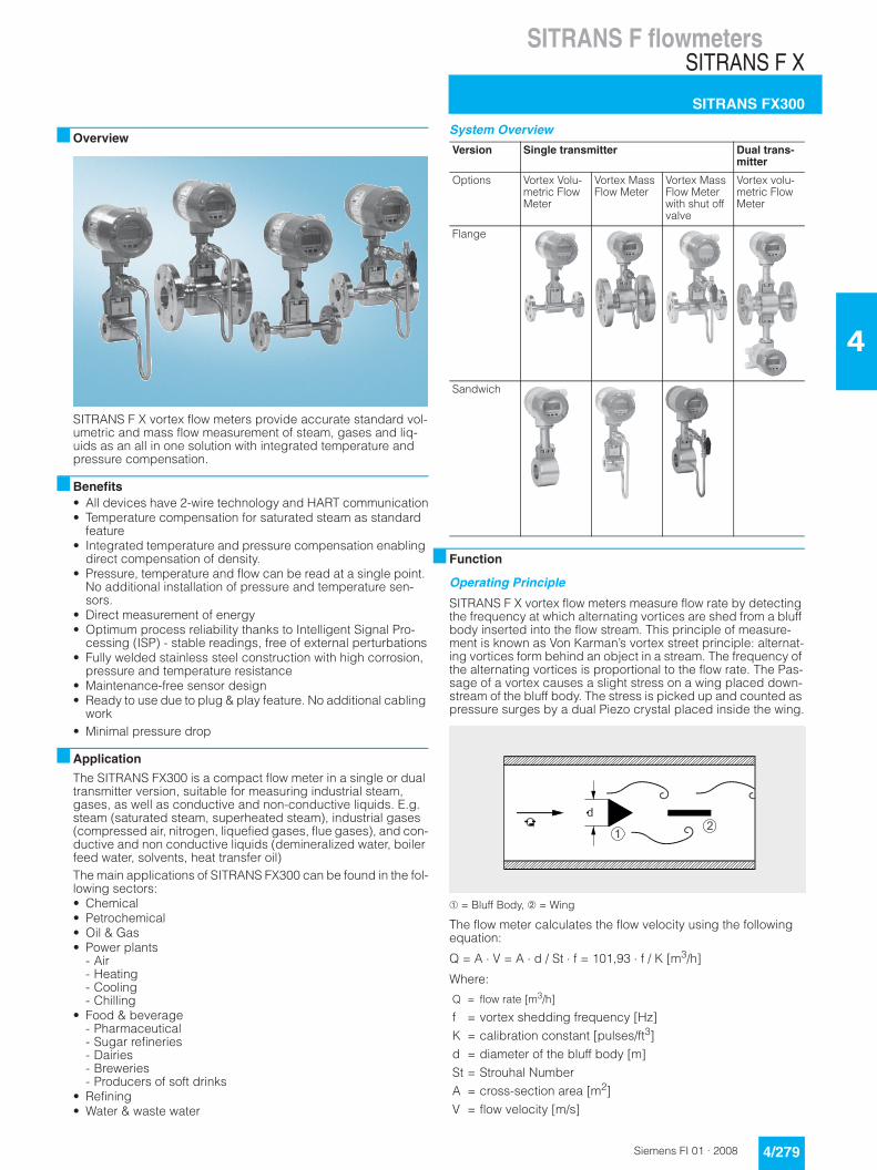
SITRANS F flowmeters SITRANS F X SITRANS FX300 4/279 Siemens FI 01 · 2008 4 ■ Overview SITRANS F X vortex flow meters provide accurate standard vol- umetric and mass flow measurement of steam, gases and liq- uids as an all in one solution with integrated temperature and pressure compensation. ■ Benefits • All devices have 2-wire technology and HART communication • Temperature compensation for saturated steam as standard feature • Integrated temperature and pressure compensation enabling direct compensation of density. • Pressure, temperature and flow can be read at a single point. No additional installation of pressure and temperature sen- sors. • Direct measurement of energy • Optimum process reliability thanks to Intelligent Signal Pro- cessing (ISP) - stable readings, free of external perturbations • Fully welded stainless steel construction with high corrosion, pressure and temperature resistance • Maintenance-free sensor design • Ready to use due to plug & play feature. No additional cabling work • Minimal pressure drop ■ Application The SITRANS FX300 is a compact flow meter in a single or dual transmitter version, suitable for measuring industrial steam, gases, as well as conductive and non-conductive liquids. E.g. steam (saturated steam, superheated steam), industrial gases (compressed air, nitrogen, liquefied gases, flue gases), and con- ductive and non conductive liquids (demineralized water, boiler feed water, solvents, heat transfer oil) The main applications of SITRANS FX300 can be found in the fol- lowing sectors: • Chemical • Petrochemical • Oil & Gas • Power plants - Air - Heating - Cooling - Chilling • Food & beverage - Pharmaceutical - Sugar refineries - Dairies - Breweries - Producers of soft drinks • Refining • Water & waste water System Overview ■ Function Operating Principle SITRANS F X vortex flow meters measure flow rate by detecting the frequency at which alternating vortices are shed from a bluff body inserted into the flow stream. This principle of measure- ment is known as Von Karman’s vortex street principle: alternat- ing vortices form behind an object in a stream. The frequency of the alternating vortices is proportional to the flow rate. The Pas- sage of a vortex causes a slight stress on a wing placed down- stream of the bluff body. The stress is picked up and counted as pressure surges by a dual Piezo crystal placed inside the wing. ➀ = Bluff Body, ➁ = Wing The flow meter calculates the flow velocity using the following equation: Q = A ⋅ V = A ⋅ d / St ⋅ f = 101,93 ⋅ f / K [m 3 /h] Where: Version Single transmitter Dual trans- mitter Options Vortex Volu- metric Flow Meter Vortex Mass Flow Meter Vortex Mass Flow Meter with shut off valve Vortex volu- metric Flow Meter Flange Sandwich Q = flow rate [m 3 /h] f = vortex shedding frequency [Hz] K = calibration constant [pulses/ft 3 ] d = diameter of the bluff body [m] St = Strouhal Number A = cross-section area [m 2 ] V = flow velocity [m/s]
Transcript of SITRANS F flowmeters SITRANS F X - Siemens · SITRANS F flowmeters SITRANS F X SITRANS FX300...
SITRANS F flowmetersSITRANS F X
SITRANS FX300
4/279Siemens FI 01 · 2008
4
■ Overview
SITRANS F X vortex flow meters provide accurate standard vol-umetric and mass flow measurement of steam, gases and liq-uids as an all in one solution with integrated temperature and pressure compensation.
■ Benefits• All devices have 2-wire technology and HART communication• Temperature compensation for saturated steam as standard
feature• Integrated temperature and pressure compensation enabling
direct compensation of density. • Pressure, temperature and flow can be read at a single point.
No additional installation of pressure and temperature sen-sors.
• Direct measurement of energy• Optimum process reliability thanks to Intelligent Signal Pro-
cessing (ISP) - stable readings, free of external perturbations• Fully welded stainless steel construction with high corrosion,
pressure and temperature resistance• Maintenance-free sensor design• Ready to use due to plug & play feature. No additional cabling
work• Minimal pressure drop
■ Application
The SITRANS FX300 is a compact flow meter in a single or dual transmitter version, suitable for measuring industrial steam, gases, as well as conductive and non-conductive liquids. E.g. steam (saturated steam, superheated steam), industrial gases (compressed air, nitrogen, liquefied gases, flue gases), and con-ductive and non conductive liquids (demineralized water, boiler feed water, solvents, heat transfer oil)The main applications of SITRANS FX300 can be found in the fol-lowing sectors:• Chemical• Petrochemical• Oil & Gas• Power plants
- Air- Heating- Cooling- Chilling
• Food & beverage - Pharmaceutical - Sugar refineries- Dairies- Breweries- Producers of soft drinks
• Refining• Water & waste water
System Overview
■ Function
Operating Principle
SITRANS F X vortex flow meters measure flow rate by detecting the frequency at which alternating vortices are shed from a bluff body inserted into the flow stream. This principle of measure-ment is known as Von Karman’s vortex street principle: alternat-ing vortices form behind an object in a stream. The frequency of the alternating vortices is proportional to the flow rate. The Pas-sage of a vortex causes a slight stress on a wing placed down-stream of the bluff body. The stress is picked up and counted as pressure surges by a dual Piezo crystal placed inside the wing.
➀ = Bluff Body, ➁ = Wing
The flow meter calculates the flow velocity using the following equation:
Q = A ⋅ V = A ⋅ d / St ⋅ f = 101,93 ⋅ f / K [m3/h]
Where:
Version Single transmitter Dual trans-mitter
Options Vortex Volu-metric Flow Meter
Vortex Mass Flow Meter
Vortex Mass Flow Meter with shut off valve
Vortex volu-metric Flow Meter
Flange
Sandwich
Q = flow rate [m3/h]
f = vortex shedding frequency [Hz]K = calibration constant [pulses/ft3]d = diameter of the bluff body [m]St = Strouhal NumberA = cross-section area [m2]V = flow velocity [m/s]

SITRANS F flowmetersSITRANS F X
SITRANS FX300
4/280 Siemens FI 01 · 2008
4
Requirements
In order to generate the vortex streets, the medium must have a minimum of velocity: • for steam and gases, the flow rate must be between 2 to
80 m/s (6.6 to 262 ft/s)• for liquids the flow rate must be between 0.4 to 10 m/s (1.3 to
32.8 ft/s).
Design
SITRANS FX300 is available in the following configurations:
SITRANS FX300 single transmitter
The single converter is available in a flange or sandwich version volumetric flow meter (standard) and as a mass flow meter (op-tional):• Vortex volumetric flow meter
Measurement with integrated temperature sensor for satu-rated steam compensation as standard feature
• Vortex mass flow meterMeasurement with integrated temperature and pressure sen-sors for compensation of gases, wet gases, gas mixtures or steam (for engergy measurement).The SITRANS FX300 mass flow meter is optionally available with: - Shut-off valves
Allowing the pressure sensor to be shut off for the purpose of pressure or leak testing of the pipeline or for being ex-changed without interrupting the process. Using the built-in two-way valve, the pressure sensor can also be calibrated and tested at a later time.
SITRANS FX300 Dual transmitter
This is a genuine redundant system with two independent sen-sors and two converters providing twofold functional reliability and availability of the measurement. This variant is optimally suited for measurements in multi product pipelines, where differ-ent products are moved through one after the other. Here one converter can be programmed for one product, and the other converter for the other.
The dual converter is available as: • Vortex volumetric flow meter
Measurement with temperature sensor for saturated steam compensation as standard feature
■ Technical specifications
Input
Measuring range limits See „Dimensional Drawings“
Media pressure 1 ... 100 bar (Higher pressures on request)
Output
Current output
• Measuring range 4 … 20 mA
• Over range 20.8 mA ± 1 % (105 % ± 1 %)
• Load Min. 100 Ω; max. Rges = (UB - 14 V) / 22 mA
• Error signal NAMUR NE 43
• Maximum output 22 mA (112.5 %)
• Multidrop mode 4 mA
Digital output
• Communication HART
• Physical layer FSK
• Device category Transmitter
Pulse Output
• Pulse frequency Max. 0.5 Hz
Power supply
• Standard version 24 V DC as NAMUR or open < 1 mA, max. 36 V, closed 100 mA, U < 2 V
• Ex version 24 V DC as NAMUR or open < 1 mA, max. 30 V, closed 100 mA, U < 2 V
Accuracy
Standard version
• For liquids- Re ≥ 20 000 ± 0.75 %
• For steam and gases- Re ≥ 20 000 ± 1 %
• For steam, gases and liquids- 10 000 < Re < 20 000 ± 2 %
Pressure and temperature compensated version
• For liquids- 10 000 < Re < 20 000 ± 2 %- Re ≥ 20 000 ± 0.75 %
• For gases and steam- 10 000 < Re < 20 000 ± 2.5 %- Re ≥ 20 000 ± 1.5 %
Installation conditions
• Inlet run ≥ 20 x DN
• Outlet run ≥ 5 x DN
Rated operation conditions
Ambient temperature
• Standard version -40 … +85 °C (-40 … +185 °F)
• Ex version -20 … +65 °C (-4 … +149 °F)
Storage temperature -50 … +85 °C (-58 … +185 °F)
Media temperature -40 … +240 °C (-40 … +464 °F)
Density Taken into consideration when rat-ing
Viscosity < 10 cP
Reynolds number 10 000 … 2 300 000
Media pressure limit Max. 100 bar(Higher pressure on request)
Design
Material
• Sensor 1.4404/316L
Hastelloy C22 (on request)
• Housing Aluminium
Aluminium seawater resistant
• Sensor gasket 1.4435/316L/FPM
Hastelloy C22/FFKM (on request)
Process connections EN or ASME flanges
• Flange version DN 15 … 300 (½ … 12")
• Sandwich version DN 15 … 100 (½ … 4")
Degree of protection IP66/IP67 (NEMA 6)
Dimensions and weights See „Dimensional Drawings“
Display and operating interface
Local display 2 lines, 10 characters per line
Languages German, English, French
Power supply
• Standard version 14 … 36 V DC
• Ex version 14 … 30 V DC
Certificates and approvals
Explosion protection
• ATEX II 2G EEx d ia [ia] IIC T6
• FM Class I, Div 1

SITRANS F flowmetersSITRANS F X
SITRANS FX300
4/281Siemens FI 01 · 2008
4
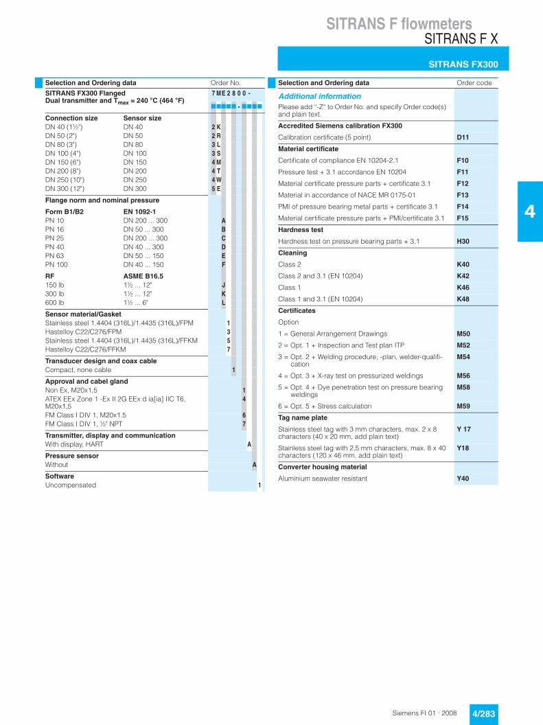
Selection and Ordering data Order No.
SITRANS FX300 FlangedSingle transmitter and Tmax = 240 °C (464 °F)
7 ME 2 6 0 0 -
77777 - 7777
Connection size Sensor size
DN 15 (½") DN 15 1 ADN 25 (1") DN 25 2 BDN 40 (1½") DN 40 2 KDN 50 (2") DN 50 2 RDN 80 (3") DN 80 3 LDN 100 (4") DN 100 3 SDN 150 (6") DN 150 4 MDN 200 (8") DN 200 4 TDN 250 (10") DN 250 4 WDN 300 (12") DN 300 5 E
Flange norm and nominal pressure
Form B1/B2 EN 1092-1PN 10 DN 200 ... 300 APN 16 DN 50 ... 300 BPN 25 DN 200 ... 300 CPN 40 DN 15 ... 300 DPN 63 DN 50 ... 150 EPN 100 DN 15 ... 150 F
RF ASME B16.5150 lb 1½ ... 12" J300 lb 1½ ... 12" K600 lb 1½ ... 6" L
Sensor material/GasketStainless steel 1.4404 (316L)/1.4435 (316L)/FPM 1Hastelloy C22/C276/FPM 3Stainless steel 1.4404 (316L)/1.4435 (316L)/FFKM 5Hastelloy C22/C276/FFKM 7
Transducer design and coax cableCompact, none cable 1
Approval and cable glandNon Ex, M20x1,5 1ATEX EEx Zone 1 -Ex II 2G EEx d ia[ia] IIC T6, M20x1,5
4
FM Class I DIV 1, M20x1.5 6FM Class I DIV 1, ½" NPT 7
Transmitter, display and communicationWith display, HART A
Pressure sensorWithout A4 bar B6 bar D10 bar E16 bar G25 bar H40 bar K60 bar L100 bar N
With iso valve4 bar P6 bar Q10 bar R16 bar S25 bar U40 bar V60 bar W100 bar Y
SoftwareUncompensated 1Density compensation for superheated steam (option only with pressure sensor)
4
Density compensation for gas-wet-mix (option only with pressure sensor)
7
Selection and Ordering data Order code
Additional informationPlease add “-Z“ to Order No. and specify Order code(s) and plain text.
Accredited Siemens calibration FX300
Calibration certificate (5 point) D11
Material certificate
Certificate of compliance EN 10204-2.1 F10
Pressure test + 3.1 accordance EN 10204 F11
Material certificate pressure parts + certificate 3.1 F12
Material in accordance of NACE MR 0175-01 F13
PMI of pressure bearing metal parts + certificate 3.1 F14
Material certificate pressure parts + PMI/certificate 3.1 F15
Hardness test
Hardness test on pressure bearing parts + 3.1 H30
Cleaning
Class 2 K40
Class 2 and 3.1 (EN 10204) K42
Class 1 K46
Class 1 and 3.1 (EN 10204) K48
Certificates
Option
1 = General Arrangement Drawings M50
2 = Opt. 1 + Inspection and Test plan ITP M52
3 = Opt. 2 + Welding procedure, -plan, welder-qualifi-cation
M54
4 = Opt. 3 + X-ray test on pressurized weldings M56
5 = Opt. 4 + Dye penetration test on pressure bearingweldings
M58
6 = Opt. 5 + Stress calculation M59
Tag name plate
Stainless steel tag with 3 mm characters, max. 2 x 8 characters (40 x 20 mm, add plain text)
Y 17
Stainless steel tag with 2,5 mm characters, max. 8 x 40 characters (120 x 46 mm, add plain text)
Y18
Converter housing material
Aluminium seawater resistant Y40
Selection and Ordering data Order No.
SITRANS FX300 FlangedSingle transmitter and Tmax = 240 °C (464 °F)
7 ME 2 6 0 0 -
77777 - 7777

SITRANS F flowmetersSITRANS F X
SITRANS FX300
4/282 Siemens FI 01 · 2008
4
Selection and Ordering data Order No.
SITRANS FX300 SandwichSingle transmitter and Tmax = 240 °C (464 °F)
7 ME 2 7 0 0 -
77777 - 7777
Connection size Sensor size
DN 15 (½") DN 15 1 ADN 25 (1") DN 25 2 BDN 40 (1½") DN 40 2 KDN 50 (2") DN 50 2 RDN 80 (3") DN 80 3 LDN 100 (4") DN 100 3 S
Nominal pressure
ENPN 100 DN 40 ... 100 R
ASME 150 lb 1½ ... 4" S300 lb 1½ ... 4" T600 lb 1½ ... 4" U
Sensor material/GasketStainless steel 1.4404 (316L)/1.4435 (316L)/FPM 1Hastelloy C22/C276/FPM 3Stainless steel 1.4404 (316L)/1.4435 (316L)/FFKM 5Hastelloy C22/C276/FFKM 7
Transducer design and coax cableCompact, none cable 1
Approval and cable glandNon Ex, M20x1,5 1ATEX EEx Zone 1 -Ex II 2G EEx d ia[ia] IIC T6, M20x1,5
4
FM Class I DIV 1, M20x1.5 6FM Class I DIV 1, ½" NPT 7
Transmitter, display and communicationWith display, HART A
Pressure sensorWithout A4 bar B6 bar D10 bar E16 bar G25 bar H40 bar K60 bar L100 bar N
With iso valve4 bar P6 bar Q10 bar R16 bar S25 bar U40 bar V60 bar W100 bar Y
SoftwareUncompensated 1Density compensation for superheated steam (option only with pressure sensor)
4
Density compensation for gas-wet-mix (option only with pressure sensor)
7
Selection and Ordering data Order code
Additional informationPlease add “-Z“ to Order No. and specify Order code(s) and plain text.
Accredited Siemens calibration FX300
Calibration certificate (5 point) D11
Material certificate
Certificate of compliance EN 10204-2.1 F10
Pressure test + 3.1 accordance EN 10204 F11
Material certificate pressure parts + certificate 3.1 F12
Material in accordance of NACE MR 0175-01 F13
PMI of pressure bearing metal parts + certificate 3.1 F14
Material certificate pressure parts + PMI/certificate 3.1 F15
Hardness test
Hardness test on pressure bearing parts + 3.1 H30
Cleaning
Class 2 K40
Class 2 and 3.1 (EN 10204) K42
Class 1 K46
Class 1 and 3.1 (EN 10204) K48
Certificates
Option
1 = General Arrangement Drawings M50
2 = Opt. 1 + Inspection and Test plan ITP M52
3 = Opt. 2 + Welding procedure, -plan, welder-qualifi-cation
M54
4 = Opt. 3 + X-ray test on pressurized weldings M56
5 = Opt. 4 + Dye penetration test on pressure bearingweldings
M58
6 = Opt. 5 + Stress calculation M59
Tag name plate
Stainless steel tag with 3 mm characters, max. 2 x 8 characters (40 x 20 mm, add plain text)
Y 17
Stainless steel tag with 2,5 mm characters, max. 8 x 40 characters (120 x 46 mm, add plain text)
Y18
Converter housing material
Aluminium seawater resistant Y40
Selection and Ordering data Order No.
SITRANS FX300 SandwichSingle transmitter and Tmax = 240 °C (464 °F)
7 ME 2 7 0 0 -
77777 - 7777
SITRANS F flowmetersSITRANS F X
SITRANS FX300
4/283Siemens FI 01 · 2008
4
Selection and Ordering data Order No.
SITRANS FX300 FlangedDual transmitter and Tmax = 240 °C (464 °F)
7 ME 2 8 0 0 -
77777 - 7777
Connection size Sensor sizeDN 40 (1½") DN 40 2 KDN 50 (2") DN 50 2 RDN 80 (3") DN 80 3 LDN 100 (4") DN 100 3 SDN 150 (6") DN 150 4 MDN 200 (8") DN 200 4 TDN 250 (10") DN 250 4 WDN 300 (12") DN 300 5 E
Flange norm and nominal pressure
Form B1/B2 EN 1092-1PN 10 DN 200 ... 300 APN 16 DN 50 ... 300 BPN 25 DN 200 ... 300 CPN 40 DN 40 ... 300 DPN 63 DN 50 ... 150 EPN 100 DN 40 ... 150 F
RF ASME B16.5150 lb 1½ ... 12" J300 lb 1½ ... 12" K600 lb 1½ ... 6" L
Sensor material/GasketStainless steel 1.4404 (316L)/1.4435 (316L)/FPM 1Hastelloy C22/C276/FPM 3Stainless steel 1.4404 (316L)/1.4435 (316L)/FFKM 5Hastelloy C22/C276/FFKM 7
Transducer design and coax cableCompact, none cable 1
Approval and cabel glandNon Ex, M20x1,5 1ATEX EEx Zone 1 -Ex II 2G EEx d ia[ia] IIC T6, M20x1,5
4
FM Class I DIV 1, M20x1.5 6FM Class I DIV 1, ½" NPT 7
Transmitter, display and communicationWith display, HART A
Pressure sensorWithout A
SoftwareUncompensated 1
Selection and Ordering data Order code
Additional informationPlease add “-Z“ to Order No. and specify Order code(s) and plain text.
Accredited Siemens calibration FX300
Calibration certificate (5 point) D11
Material certificate
Certificate of compliance EN 10204-2.1 F10
Pressure test + 3.1 accordance EN 10204 F11
Material certificate pressure parts + certificate 3.1 F12
Material in accordance of NACE MR 0175-01 F13
PMI of pressure bearing metal parts + certificate 3.1 F14
Material certificate pressure parts + PMI/certificate 3.1 F15
Hardness test
Hardness test on pressure bearing parts + 3.1 H30
Cleaning
Class 2 K40
Class 2 and 3.1 (EN 10204) K42
Class 1 K46
Class 1 and 3.1 (EN 10204) K48
Certificates
Option
1 = General Arrangement Drawings M50
2 = Opt. 1 + Inspection and Test plan ITP M52
3 = Opt. 2 + Welding procedure, -plan, welder-qualifi-cation
M54
4 = Opt. 3 + X-ray test on pressurized weldings M56
5 = Opt. 4 + Dye penetration test on pressure bearingweldings
M58
6 = Opt. 5 + Stress calculation M59
Tag name plate
Stainless steel tag with 3 mm characters, max. 2 x 8 characters (40 x 20 mm, add plain text)
Y 17
Stainless steel tag with 2,5 mm characters, max. 8 x 40 characters (120 x 46 mm, add plain text)
Y18
Converter housing material
Aluminium seawater resistant Y40
SITRANS F flowmetersSITRANS F X
SITRANS FX300
4/284 Siemens FI 01 · 2008
4
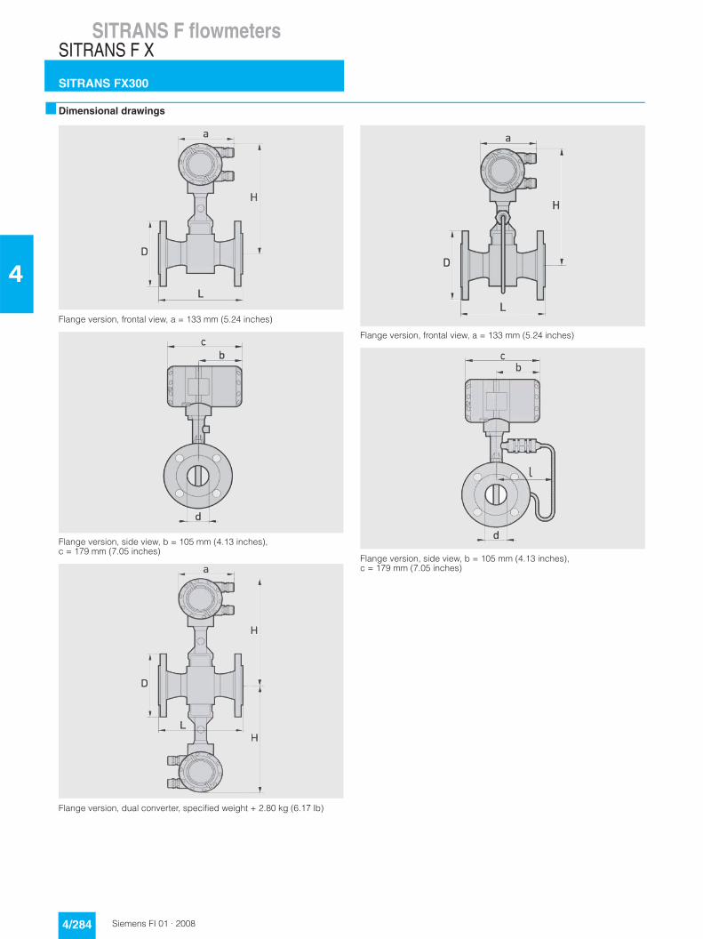
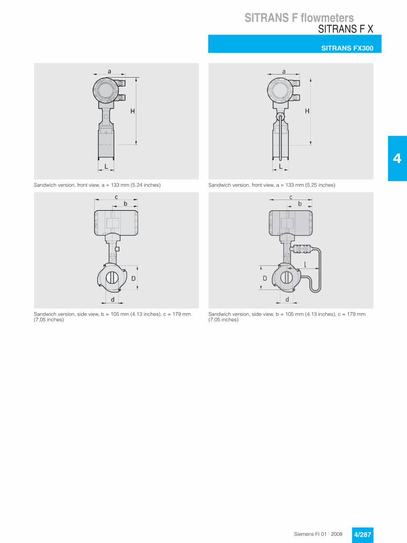
■ Dimensional drawings
Flange version, frontal view, a = 133 mm (5.24 inches)
Flange version, side view, b = 105 mm (4.13 inches), c = 179 mm (7.05 inches)
Flange version, dual converter, specified weight + 2.80 kg (6.17 lb)
Flange version, frontal view, a = 133 mm (5.24 inches)
Flange version, side view, b = 105 mm (4.13 inches), c = 179 mm (7.05 inches)

SITRANS F flowmetersSITRANS F X
SITRANS FX300
4/285Siemens FI 01 · 2008
4
Flange version EN1092-1
Size Pressure rating
Dimensions [mm (inches)] Weight [kg (lb)]
DN PN d D L H l Mass meter (with pressure sensor)
Volumetric meter (without pressure sen-sor)
15 40 17.3 (0.68) 95 (3.74) 200 (7.87) 265 (10.43) 144 (5.67) 6.1 (13.45) 5.5 (12.13)
15 100 17.3 (0.68) 105 (4.13) 200 (7.87) 265 (10.43) 144 (5.67) 7.1 (15.65) 6.5 (14.33)
25 40 28.5 (1.12) 115 (4.53) 200 (7.87) 265 (10.43) 144 (5.67) 7.9 (17.42) 7.3 (16.09)
25 100 28.5 (1.12) 140 (5.51) 200 (7.87) 265 (10.43) 144 (5.67) 9.9 (21.83) 9.3 (20.50)
40 40 43.1 (1.70) 150 (5.91) 200 (7.87) 270 (10.63) 144 (5.67) 10.8 (23.81) 10.2 (22.49)
40 100 42.5 (1.67) 170 (6.69) 200 (7.87) 270 (10.63) 144 (5.67) 14.8 (32.63) 14.2 (31.31)
50 16 54.5 (2.15) 165 (6.50) 200 (7.87) 275 (10.83) 144 (5.67) 12.7 (28.00) 12.1 (26.68)
50 40 54.5 (2.15) 165 (6.50) 200 (7.87) 275 (10.83) 144 (5.67) 12.9 (28.44) 12.3 (27.12)
50 63 54.5 (2.15) 180 (7.09) 200 (7.87) 275 (10.83) 144 (5.67) 16.9 (37.26) 16.3 (35.94)
50 100 53.9 (2.12) 195 (7.68) 200 (7.87) 275 (10.83) 144 (5.67) 18.4 (40.57) 17.8 (39.24)
80 16 82.5 (3.25) 200 (7.87) 200 (7.87) 290 (11.42) 154 (6.06) 17.4 (38.36) 16.8 (37.04)
80 40 82.5 (3.25) 200 (7.87) 200 (7.87) 290 (11.42) 154 (6.06) 19.4 (42.77) 18.8 (41.45)
80 63 81.7 (3.22) 215 (8.46) 200 (7.87) 290 (11.42) 154 (6.06) 23.4 (51.59) 22.8 (50.27)
80 100 80.9 (3.19) 230 (9.06) 200 (7.87) 290 (11.42) 154 (6.06) 27.4 (60.41) 26.8 (59.08)
100 16 107.1 (4.22) 220 (8.66) 250 (9.84) 310 (12.20) 164 (6.46) 22 (48.50) 21.4 (47.18)
100 40 107.1 (4.22) 235 (9.25) 250 (9.84) 310 (12.20) 164 (6.46) 25 (55.12) 24.4 (53.79)
100 63 106.3 (4.19) 250 (9.84) 250 (9.84) 310 (12.20) 164 (6.46) 30 (66.14) 29.4 (64.82)
100 100 104.3 (4.11) 265 (10.43) 250 (9.84) 310 (12.20) 164 (6.46) 36 (79.37) 35.4 (78.04)
150 16 159.3 (6.27) 285 (11.22) 300 (11.81) 325 (12.80) 174 (6.85) 35.8 (78.93) 35.2 (77.60)
150 40 159.3 (6.27) 300 (11.81) 300 (11.81) 325 (12.80) 174 (6.85) 41.8 (92.15) 41.2 (90.83)
150 63 157.1 (6.19) 345 (13.58) 300 (11.81) 325 (12.80) 174 (6.85) 59.8 (131.84) 59.2 (130.51)
150 100 154.1 (6.07) 355 (13.98) 300 (11.81) 325 (12.80) 174 (6.85) 67.8 (149.47) 67.2 (148.15)
200 10 206.5 (8.13) 340 (13.39) 300 (11.81) 350 (13.78) 194 (7.64) 38.4 (84.66) 37.8 (83.33)
200 16 206.5 (8.13) 340 (13.39) 300 (11.81) 350 (13.78) 194 (7.64) 38.4 (84.66) 37.8 (83.33)
200 25 206.5 (8.13) 360 (14.17) 300 (11.81) 350 (13.78) 194 (7.64) 47.4 (104.50) 46.8 (103.18)
200 40 206.5 (8.13) 375 (14.76) 300 (11.81) 350 (13.78) 194 (7.64) 55.4 (122.14) 54.8 (120.81)
250 10 260.4 (10.25) 395 (15.55) 380 (14.96) 370 (14.57) 224 (8.82) 58.0 (127.87) 57.4 (126.55)
250 16 260.4 (10.25) 405 (15.94) 380 (14.96) 370 (14.57) 224 (8.82) 59.0 (130.07) 58.4 (128.75)
250 25 258.8 (10.19) 425 (16.73) 380 (14.96) 370 (14.57) 224 (8.82) 75.0 (165.35) 74.4 (164.02)
250 40 258.8 (10.19) 450 (17.72) 380 (14.96) 370 (14.57) 224 (8.82) 93.0 (205.03) 92.4 (203.71)
300 10 309.7 (12.19) 445 (17.52) 450 (17.72) 395 (15.55) 244 (9.61) 76.3 (168.21) 75.7 (166.89)
300 16 309.7 (12.19) 460 (18.11) 450 (17.72) 395 (15.55) 244 (9.61) 82.8 (182.54) 82.2 (181.22)
300 25 307.9 (12.12) 485 (19.09) 450 (17.72) 395 (15.55) 244 (9.61) 99.3 (218.92) 98.7 (217.60)
300 40 307.9 (12.12) 515 (20.28) 450 (17.72) 395 (15.55) 244 (9.61) 128.1 (282.41) 127.5 (281.09)

SITRANS F flowmetersSITRANS F X
SITRANS FX300
4/286 Siemens FI 01 · 2008
4
Flange version ASME B16.5
Size Pressure rating
Dimensions [mm (inches)] Weight [kg (lb)]
DN class d D L H l Mass meter (with pressure sensor)
Volumetric meter (without pressure sen-sor)
½ 150 15.8 (0.62) 90 (3.54) 200 (7.87) 265 (10.43) 144 (5.67) 5.1 (11.24) 4.5 (9.92)
½ 300 15.8 (0.62) 95 (3.74) 200 (7.87) 265 (10.43) 144 (5.67) 5.5 (12.13) 4.9 (10.80)
½ 600 13.9 (0.55) 95 (3.74) 200 (7.87) 265 (10.43) 144 (5.67) 5.7 (12.57) 5.1 (11.24)
1 150 26.6 (1.05) 110 (4.33) 200 (7.87) 265 (10.43) 144 (5.67) 6.8 (14.99) 6.2 (13.67)
1 300 26.6 (1.05) 125 (4.92) 200 (7.87) 265 (10.43) 144 (5.67) 7.8 (17.20) 7.2 (15.87)
1 600 24.3 (0.96) 125 (4.92) 200 (7.87) 265 (10.43) 144 (5.67) 8.1 (17.86) 7.5 (16.53)
1½ 150 40.9 (1.61) 125 (4.92) 200 (7.87) 270 (10.63) 144 (5.67) 8.9 (19.62) 8.3 (18.30)
1½ 300 40.9 (1.61) 155 (6.10) 200 (7.87) 270 (10.63) 144 (5.67) 11 (24.25) 10.4 (22.93)
1½ 600 38.1 (1.50) 155 (6.10) 200 (7.87) 270 (10.63) 144 (5.67) 12 (26.46) 11.4 (25.13)
2 150 52.6 (2.07) 150 (5.91) 200 (7.87) 275 (10.83) 144 (5.67) 11.6 (25.57) 11 (24.25)
2 300 52.6 (2.07) 165 (6.50) 200 (7.87) 275 (10.83) 144 (5.67) 13 (28.66) 12.4 (27.34)
2 600 49.3 (1.94) 165 (6.50) 200 (7.87) 275 (10.83) 144 (5.67) 14.5 (31.97) 13.9 (30.64)
3 150 78 (3.07) 190 (7.48) 200 (7.87) 290 (11.42) 154 (6.06) 20.4 (44.97) 19.8 (43.65)
3 300 78 (3.07) 210 (8.27) 200 (7.87) 290 (11.42) 154 (6.06) 23.4 (51.59) 22.8 (50.27)
3 600 73.7 (2.90) 210 (8.27) 200 (7.87) 290 (11.42) 154 (6.06) 24.4 (53.79) 23.8 (52.47)
4 150 102.4 (4.03) 230 (9.06) 250 (9.84) 310 (12.20) 164 (6.46) 24 (52.91) 23.4 (51.59)
4 300 102.4 (4.03) 255 (10.04) 250 (9.84) 310 (12.20) 164 (6.46) 32 (70.55) 31.4 (69.23)
4 600 97.2 (3.83) 275 (10.83) 250 (9.84) 310 (12.20) 164 (6.46) 41 (90.39) 40.4 (89.07)
6 150 154.2 (6.07) 280 (11.02) 300 (11.81) 325 (12.80) 174 (6.85) 36.8 (81.13) 36.2 (79.81)
6 300 154.2 (6.07) 320 (12.60) 300 (11.81) 325 (12.80) 174 (6.85) 51.8 (114.20) 51.2 (112.88)
6 600 146.3 (5.76) 355 (13.98) 300 (11.81) 325 (12.80) 174 (6.85) 76.8 (169.31) 46.2 (101.85)
8 150 202.7 (7.98) 345 (13.58) 300 (11.81) 350 (13.78) 194 (7.64) 50.6 (111.55) 50.0 (110.23)
8 300 202.7 (7.98) 380 (14.96) 300 (11.81) 350 (13.78) 194 (7.64) 75.4 (166.23) 74.8 (164.91)
10 150 254.5 (10.02) 405 (15.94) 380 (14.96) 370 (14.57) 224 (8.82) 75.0 (165.35) 74.4 (164.02)
10 300 254.5 (10.02) 455 (17.91) 380 (14.96) 370 (14.57) 224 (8.82) 107.0 (235.89) 106.4 (234.57)
12 150 304.8 (12.00) 485 (19.09) 450 (17.72) 395 (15.55) 244 (9.61) 106.9 (235.67) 106.3 (234.35)
12 300 304.8 (12.00) 520 (20.47) 450 (17.72) 395 (15.55) 244 (9.61) 151.9 (334.88) 151.3 (333.56)
SITRANS F flowmetersSITRANS F X
SITRANS FX300
4/287Siemens FI 01 · 2008
4
Sandwich version, front view, a = 133 mm (5.24 inches)
Sandwich version, side view, b = 105 mm (4.13 inches), c = 179 mm (7,05 inches)
Sandwich version, front view, a = 133 mm (5.25 inches)
Sandwich version, side view, b = 105 mm (4.13 inches), c = 179 mm (7.05 inches)
SITRANS F flowmetersSITRANS F X
SITRANS FX300
4/288 Siemens FI 01 · 2008
4
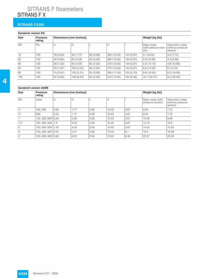
Sandwich version EN
Size Pressure rating
Dimensions [mm (inches)] Weight [kg (lb)]
DN PN d D L H l Mass meter (with pressure sen-sor)
Volumetric meter (without pressure sensor)
15 100 16 (0.63) 45 (1.77) 65 (2.56) 265 (10.43) 144 (5.67) 4.1 (9.04) 3.5 (7.72)
25 100 24 (0.94) 65 (2.56) 65 (2.56) 265 (10.43) 144 (5.67) 4.9 (10.80) 4.3 (9.48)
40 100 38 (1.50) 82 (3.23) 65 (2.56) 270 (10.63) 144 (5.67) 5.5 (12.13) 4.9 (10.80)
50 100 50 (1.97) 102 (4.02) 65 (2.56) 275 (10.83) 144 (5.67) 6.6 (14.55) 6 (13.23)
80 100 74 (2.91) 135 (5.31) 65 (2.56) 290 (11.42) 155 (6.10) 8.8 (19.40) 8.2 (18.08)
100 100 97 (3.82) 158 (6.22) 65 (2.56) 310 (12.20) 164 (6.46) 10.1 (22.27) 9.5 (20.94)
Sandwich version ASME
Size Pressure rating
Dimensions [mm (inches)] Weight [kg (lb)]
DN class d D L H l Mass meter (with pressure sensor)
Volumetric meter (without pressure sensor)
½" 150, 300 0.63 1.77 2.56 10.43 5.67 9.04 7.72
½" 600 0.55 1.77 2.56 10.43 5.67 9.04 7.72
1" 150, 300, 600 0.94 2.56 2.56 10.43 5.67 10.08 9.48
1½" 150, 300, 600 1.5 3.23 2.56 10.43 5.67 12.13 10.8
2" 150, 300, 600 1.97 4.02 2.56 10.43 5.67 14.55 13.23
3" 150, 300, 600 2.91 5.31 2.56 10.43 6.1 19.4 18.08
4" 150, 300, 600 3.82 6.22 2.56 10.43 6.46 22.27 20.94
SITRANS F flowmetersSITRANS F X
SITRANS FX300
4/289Siemens FI 01 · 2008
4
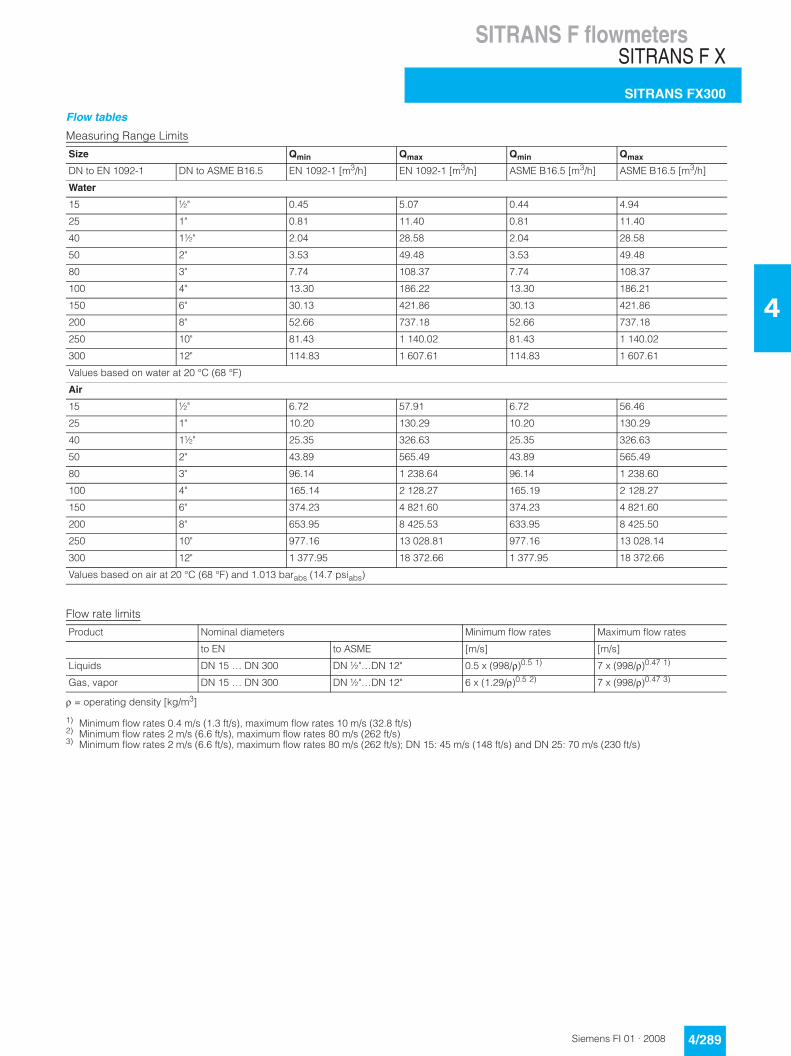
Flow tables
Measuring Range Limits
Flow rate limits
ρ = operating density [kg/m3]
1) Minimum flow rates 0.4 m/s (1.3 ft/s), maximum flow rates 10 m/s (32.8 ft/s)2) Minimum flow rates 2 m/s (6.6 ft/s), maximum flow rates 80 m/s (262 ft/s)3) Minimum flow rates 2 m/s (6.6 ft/s), maximum flow rates 80 m/s (262 ft/s); DN 15: 45 m/s (148 ft/s) and DN 25: 70 m/s (230 ft/s)
Size Qmin Qmax Qmin Qmax
DN to EN 1092-1 DN to ASME B16.5 EN 1092-1 [m3/h] EN 1092-1 [m3/h] ASME B16.5 [m3/h] ASME B16.5 [m3/h]
Water
15 ½" 0.45 5.07 0.44 4.94
25 1" 0.81 11.40 0.81 11.40
40 1½" 2.04 28.58 2.04 28.58
50 2" 3.53 49.48 3.53 49.48
80 3" 7.74 108.37 7.74 108.37
100 4" 13.30 186.22 13.30 186.21
150 6" 30.13 421.86 30.13 421.86
200 8" 52.66 737.18 52.66 737.18
250 10" 81.43 1 140.02 81.43 1 140.02
300 12" 114.83 1 607.61 114.83 1 607.61
Values based on water at 20 °C (68 °F)
Air
15 ½" 6.72 57.91 6.72 56.46
25 1" 10.20 130.29 10.20 130.29
40 1½" 25.35 326.63 25.35 326.63
50 2" 43.89 565.49 43.89 565.49
80 3" 96.14 1 238.64 96.14 1 238.60
100 4" 165.14 2 128.27 165.19 2 128.27
150 6" 374.23 4 821.60 374.23 4 821.60
200 8" 653.95 8 425.53 633.95 8 425.50
250 10" 977.16 13 028.81 977.16 13 028.14
300 12" 1 377.95 18 372.66 1 377.95 18 372.66
Values based on air at 20 °C (68 °F) and 1.013 barabs (14.7 psiabs)
Product Nominal diameters Minimum flow rates Maximum flow rates
to EN to ASME [m/s] [m/s]
Liquids DN 15 … DN 300 DN ½"…DN 12" 0.5 x (998/ρ)0.5 1) 7 x (998/ρ)0.47 1)
Gas, vapor DN 15 … DN 300 DN ½"…DN 12" 6 x (1.29/ρ)0.5 2) 7 x (998/ρ)0.47 3)

SITRANS F flowmetersSITRANS F X
SITRANS FX300
4/290 Siemens FI 01 · 2008
4
Measuring range saturated steam: 1 to 7 bar
Measuring range saturated steam: 10.5 to 20 bar
Overpressure [bar] 1 3.5 5.2 7
Density [kg/m³] 1.13498 2.4258 3.27653 4.16732
Temperature [°C] 120.6 148.2 160.4 170.6
Flow [kg/h] min. max. min. max. min. max. min. max.
DN to EN 1092-1
DN to ASME B16.5
15 ½" 5.25 65.72 7.68 140.47 8.93 189.73 10.06 241.31
25 1" 11.82 147.87 17.28 316.05 20.09 426.89 22.66 542.95
40 1½" 29.64 370.71 43.33 792.33 50.63 1 070.2 56.8 1 361.2
50 2" 51.31 641.82 75.02 1 371.8 87.19 1 852.8 98.33 2 356.6
80 3" 112.41 1 405.8 164.33 3 004.7 191 4 058.4 215.39 5 161.8
100 4" 193.14 2 415.5 282.36 5 162.7 328.16 6 973.3 370.09 8 869.2
150 6" 437.56 5 472.4 639.69 11 696 743.45 15 798 838.44 20 093
200 8" 764.62 9 562.8 1 117.8 20 439 1 299.2 27 606 1 465.1 35 112
250 10" 1 177.07 14 655.07 1 716.4 31 161.66 1 993.6 42 039.68 2 247.44 53 426.86
300 12" 1 659.85 20 665.94 2 420.39 43 942.81 2 811.29 58 282.52 3 169.24 75 340.22
Overpressure [bar] 10.5 14 17.5 20
Density [kg/m³] 5.88803 7.60297 9.31702 10.5442
Temperature [°C] 186.2 198.5 208.5 215
Flow [kg/h] min. max. min. max. min. max. min. max.
DN to EN 1092-1
DN to ASME B16.5
15 ½" 12.78 332.97 16.51 381.28 20.23 424.66 22.89 453.44
25 1" 26.93 749.18 30.6 857.88 33.87 955.48 36.04 1 020.2
40 1½" 67.51 1 878.2 76.72 2 150.7 84.93 2 395.3 90.35 2 557.7
50 2" 116.89 3 251.7 132.82 3 723.4 147.03 4 147 156.42 4 428.1
80 3" 256.03 7 122.4 290.93 8 155.8 322.06 9 083.7 342.62 9 699.3
100 4" 439.91 12 238 499.9 14 013 553.38 15 608 588.69 16 666
150 6" 996.62 27 725 1 132.5 31 747 1 253.7 35 359 1 333.7 37 756
200 8" 1 741.6 48 449 1 979 55 478 2 190.7 61 789 2 330.6 65 977
250 10" 2 670.28 66 065.16 3 033.45 75 626.77 3 357.4 84 214.04 3 571 89 910.45
300 12" 3 765.52 93 162.2 4 277.65 106 645.56 4 737.45 118 754 5 036.01 126 787.78

SITRANS F flowmetersSITRANS F X
SITRANS FX300
4/291Siemens FI 01 · 2008
4
Measuring range saturated steam: 15 to 100 psig
Measuring range saturated steam: 150 to 300 psig
Overpressure [psig] 15 50 75 100
Density [lbs/ft³] 0.0719 0.1497 0.2036 0.2569
Temperature [°F] 249.98 297.86 320.36 338.184
Flow [lbs/h] min. max. min. max. min. max. min. max.
DN to EN 1092-1
DN to ASME B16.5
15 ½" 11.6 147.08 16.83 306 19.62 416.04 22.04 524.86
25 1" 26.25 330.92 37.86 688.48 44.15 936.09 49.59 1 180.9
40 1½" 65.81 829.61 94.92 1 726 110.68 2 346.7 124.32 2 960.5
50 2" 113.94 1 436.3 164.34 2 988 191.63 4 062.9 215.23 5 125.6
80 3" 249.57 3 146.1 360 6 545.3 419.74 8 899.4 471.45 11 227
100 4" 428.81 5 405.7 618.51 11 246 721.21 15 291 810.06 19 291
150 6" 971.47 12 246 1 401.2 25 478 1 633.9 34 642 1 835.2 43 703
200 8" 1 697.6 21 400 2 448.6 44 523 2 855.2 60 536 3 206.9 76 369
250 10" 2 562.72 32 308.86 3 777.85 68 699.63 4 371.7 92 681.52 4 946.03 117 785.23
300 12" 3 613.84 45 560.54 5 327.61 96 877.61 6 164.78 130 695.42 6 974.68 166 096.57
Overpressure [psig] 150 200 250 300
Density [lbs/ft³] 0.3627 0.4681 0.5735 0.6792
Temperature [°F] 366.08 388.04 406.22 422.06
Flow [lbs/h] min. max. min. max. min. max. min. max.
DN to EN 1092-1
DN to ASME B16.5
15 ½" 27.79 728.25 35.86 833.73 43.94 928.44 52.04 1 015.5
25 1" 58.93 1 638.6 66.94 1 875.9 74.1 2 089 80.63 2 284.9
40 1½" 147.72 4 107.2 167.83 4 702.8 185.76 5 237 202.15 5 728
50 2" 255.75 7 111.9 290.56 8 141.9 321.6 9 066.8 350 9 917
80 3" 560.19 15 578 636.44 17 834 704.43 19 860 766.6 21 722
100 4" 962.54 26 766 1 093.5 30 643 1 210.4 34 124 1 317.2 37 324
150 6" 2 180.6 60 639) 2 477.4 69 421 2 742.1 77 307 2 984 84 556
200 8" 3 810.6 105 96054 4 329.2 121 310 4 791.7 135 090 5 214.5 147 760
250 10" 5 876.29 145 648.57 6 674.55 166 728.29 7 386.91 185 659.96 7 680.16 198 218.37
300 12" 8 286.49 205 387.25 9 412.15 235 112.94 10 416.7 261 809.55 10 830.22 279 518.87