
SITOP Power Supply - Siemens
44
siemens.com/sitop Edition 01/2021 SITOP Power Supply Top integration. Top efficiency. Top reliability.
Transcript of SITOP Power Supply - Siemens

siemens.com/sitop
Edition 01/2021
SITOP Power Supply Top integration. Top efficiency. Top reliability.

SITOP power supplies bring production plants to life.
An efficient power supply is a basic requirement for operating any plant, no matter
the industry or need. Critical production processes can only be maintained if a con-
stant power supply of the necessary quality is available for the automation system.
For decades, SITOP – the heart of automation – has been bringing production plants
to life. The complete, precisely coordinated range of products guarantees a reliable
power supply, and is especially suited to the growing demands of our time.
SITOP PSU6200 – the all-around power supply for a wide range of applications, now also for deployment in hazardous areas – see page 8/9 and technical data on page 26/27.
2
SITOP PSU8600 – A new basic 4 x 5 A device enables the power supply system’s unique functions, including in single-phase networks – see page 6/7 and technical data on page 20.

SITOP means top reliability
SITOP has proven its reliability in nearly all networks around the world. With a flexible, wide-range input, outstanding load characteristics, and all the relevant certifications, SITOP power supply units safeguard the availability of your plant. Add-on modules prevent problems on the line or DC side. And when upgraded to an uninterruptible power supply, the 24-V power supply units bridge power failures for a period of seconds, minutes, or hours. In the event of a fault-specific overload or short circuit in the output circuit, selective disconnection of
The switched-mode power supply units in the Advanced performance class are the optimal choice for maximum reliability and functionality as required in the process and automotive industries, in special-purpose machine manufac-turing, and in harsh environments. The SITOP PSU8200 product line meets these extreme requirements thanks, for example, to their overload behavior, efficiency, and compact-ness. SITOP PSU8600 also offers a power supply system with open communication for optimal integration into the digital environment.
Our standard portfolio was designed for industrial applica-tions like those in special-purpose machine manufacturing. Development of the new SITOP PSU6200 all-around power supply was based on our experience with the proven SITOP smart product line. This new SITOP standard power supply features even higher efficiency, comprehensive diagnostic options, and greater ruggedness.
From flat power supplies for distribution boards to costeffec-tive basic power supplies and slim power supply units for control boxes – even in the low-performance range, SITOP leaves nothing to be desired. LOGO!Power offers you minia-ture power supply units in the LOGO!8 module design. And SITOP lite meets the most mportant requirements for reliable primary switched-mode regulators at an affordable price.
SITOP means top efficiency
Reduced energy costs are a valuable competitive advantage. SITOP makes an important contribution, because the primary switched-mode power supply units operate highly efficiently. For example, SITOP PSU8200 and 6200 have an efficiency of up to 96 percent. Losses are low throughout the entire load range, even in no-load operation. This is because a power supply is rarely operated at full load. SITOP PSU8600, on the other hand, records power data from all outputs, which is then further processed in energy management systems. And via PROFIenergy, power supply outputs can be switched off selectively: for example, during breaks.
SITOP is top in integration
SITOP sets a benchmark in terms of integration: Complete integration of the SITOP PSU8600 power supply system and SITOP UPS1600 DC UPS in Totally Integrated Automation, the TIA Portal, and the new SITOP Manager saves time and money and facilitates fail-safe engineering. For the selec-tivity modules and the SITOP PSU6200 product line, S7 function blocks evaluate important diagnostic information. The SITOP UPS1600 can easily be integrated via USB or Ethernet to protect PC-based automation systems from power failures. And the SITOP library for SIMATIC PCS 7
Three SITOP categories for the different demands on an industrial power supply
the feeder ensures continued operation, because the supply to other loads is maintained. For highly critical applications, redundant power supply solutions are also an option. If a replacement is ever needed, our global customer service ensures the fastest possible delivery: All SITOP products can be supplied from stock.
enables a transparent 24-V supply in the process control system during ongoing operation.Besides PROFINET, SITOP PSU8600 and SITOP UPS1600 also communicate via OPC UA. With the OPC UA server, it’s also possible to directly integrate units such as control-lers or PCs into automation applications with OPC UA clients from different vendors.
Efficiency also characterizes the product lifecycle. With the TIA Selection Tool, we offer you special tools to make it easy to select a power supply and DC UPS. We provide you with all the design data for all common CAE systems as well as the corresponding product documentation.
Advanced power supplies
Standard power supplies
Basic power supplies
3

What an optimal power supply looks like depends on numerous factors –
size, performance range, and functions, to name but a few. The extensive
range of SITOP products ensures that your power supply will always match
your requirements.
Overview of SITOP product lines
SITOP PSU6200
The all-around power supply for a wide range of applications
SITOP PSU6200 is the extremely high- performance power supply for standard 24-, 12-, and 48-V applications. The com-pact and energy-efficient power supply units offer comprehensive functions and features for focused diagnostics, fast installation, and dependable operation. Whether it’s LED status indicators, inte-gration into preventive maintenance, push-in terminals, or rugged input – SITOP PSU6200 has it all.
Pages 26–27
SITOP smart
The powerful standard power supply
SITOP smart is the optimal power supply for many 24-V and 12-V applications, featuring powerful performance and an affordable price. Even large loads can be easily switched on, thanks to its overload characteristics that provide 1.5 times the rated current for 5 seconds. And with a rated capacity of 120 percent at ambient temperatures up to 45°C, these slim power supply units are among the most reliable of their kind.
Pages 28–29
SITOP PSU8200
The technology power supply for demanding solutions
SITOP PSU8200 is ideal for complex plants and machines. The wide-range input allows it to be connected to any supply system and also to withstand large voltage fluctuations. The power boost briefly delivers up to three times the rated current. And in the event of an overload, you can choose between constant current with automatic restart or latching shutdown. The high degree of efficiency reduces energy consumption, while the compact metal enclosure saves space.
Pages 24–25
Advanced power supplies Standard power supplies
New: now also for hazardous areas
4
SITOP PSU8600
The power supply system for digitaliza-tion and Industry 4.0
The innovative SITOP PSU8600 power sup-ply system is fully integrated into Totally Integrated Automation and the TIA Portal. It’s integrated directly into networked automation applications via its Ethernet/PROFINET interface or OPC UA. SITOP PSU8600 offers unique functions and diag-nostics options. The modular system can be expanded to 36 outputs and provides buffer and DC UPS modules for protection against power failures.
Pages 20–23

SITOP DC/DC converter
Stable power supply despite fluctuat-ing DC voltage
SITOP DC/DC converters provide a stable control voltage: in battery-powered vehicles, as a “refresher” on long lines, in power plants, and at the DC link converter of wind energy plants and machine tools.
Page 34–35
LOGO!Power
The flat power supply for distribution boards
Small. Clever. LOGO!Power. The fourth generation of the globally proven miniature power supply units with a flat, stepped profile features high perfor-mance in a small space. The comprehen-sive functionality with flexible installa-tion, current monitoring, and high energy efficiency permits universal use in appli-cations with 5 V, 12 V, 15 V, and 24 V.
Pages 30–31
SITOP lite
The cost-effective basic power supply
SITOP lite is the power supply series for basic requirements in the industrial environment, offering all the important functions at a low cost – without compro-mising quality and reliability. The wide-range input with manual switchover supports connection to a wide range of single-phase supply systems.
Page 32
The optimal supply for SIMATIC S7 and more
Page 33
Equipped for special functions and conditions
Pages 36–37
Basic power supplies SIMATIC Design
Special designs
SITOP DC/DC converters
5

Advanced power supplies
Did you know that… even in buffer operation, the outputs exactly hold their set voltage and do not vary with battery voltage, as is common in other DC UPS systems?
Complex plants set high requirements for the efficiency, flexibility and reliability of
the components used. The innovative power supply system SITOP PSU8600 fulfills
them all – thanks to its unique functionality, diagnostics capability, modular ex-
pandability and complete integration in TIA or via an OPC-UA server in many other
systems.
SITOP PSU8600 – the power supply system for digitalization and Industry 4.0
SITOP PSU8600 – in dialog with your power supply
The SITOP power supply system includes the SITOP PSU8600 basic unit, the SITOP CNX8600 add-on modules, the SITOP BUF8600 buffer modules and the SITOP UPS8600 UPS mod-ule with the BAT8600 battery modules. It can be integrated seamlessly in TIA Portal, SIMATIC PCS 7 and WinCC. Due to the comprehensive data exchange over PROFINET or OPC-UA, the power supply is in constant dialog with the control unit and thus enables preventive maintenance and energy man-agement in the control and load circuit.
SITOP PSU8600 System – modular and integrated
SITOP BUF8600 buffer modules
SITOP CNX8600expansion modules
SITOP PSU8600base units
Integration PROFINET, OPC-UA
Controller Monitoring Engineering with TIA Portal Open communication
SITOP PSU8600UPS modules
SITOP PSU8600battery modules
6
Advanced power supplies
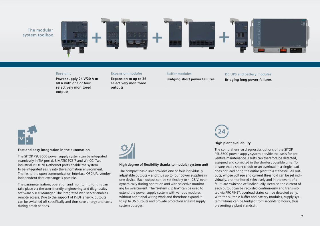
Fast and easy integration in the automation
The SITOP PSU8600 power supply system can be integrated seamlessly in TIA portal, SIMATIC PCS 7 and WinCC. Two industrial PROFINET/ethernet ports enable the system to be integrated easily into the automation environment. Thanks to the open communication interface OPC UA, vendor-independent data exchange is possible.
The parameterization, operation and monitoring for this can take place via the user-friendly engineering and diagnostics software SITOP Manager. The integrated web server enables remote access. Due to the support of PROFIenergy, outputs can be switched off specifically and thus save energy and costs during break periods.
Buffer modulesBridging short power failures
Base unitPower supply 24 V/20 A or 40 A with one or four selectively monitored outputs
Expansion modulesExpansion to up to 36 selectively monitored outputs
The modular system toolbox
DC UPS and battery modulesBridging long power failures
High degree of flexibility thanks to modular system unit
The compact basic unit provides one or four individually adjustable outputs – and thus up to four power supplies in one device. Each output can be set flexibly to 4–28 V, even dynamically during operation and with selective monitor-ing for overcurrent. The “system clip link” can be used to extend the power supply system with various modules without additional wiring work and therefore expand it to up to 36 outputs and provide protection against supply system outages.
High plant availability
The comprehensive diagnostics options of the SITOP PSU8600 power supply system provide the basis for pre-ventive maintenance. Faults can therefore be detected, assigned and corrected in the shortest possible time. To ensure that a short-circuit or an overload in a single load does not lead bring the entire plant to a standstill. All out-puts, whose voltage and current threshold can be set indi-vidually, are monitored selectively and in the event of a fault, are switched off individually. Because the current of each output can be recorded continuously and transmit-ted via PROFINET, overload states can be detected early. With the suitable buffer and battery modules, supply sys-tem failures can be bridged from seconds to hours, thus preventing a plant standstill.
7

Standard power supplies
Output voltage o.k.
Output voltage o.k.
Utilization > 30% < 30% > 60% > 90%
< 10%
Diagnostics monitor/Diagnostics interfaceSITOP PSU6200 power supply units as of 24 V/10 A, 12 V/12 A and 48 V/5 A have a diagnostics monitor and a diagnostics interface. The diagnostics monitor indicates their operating status, current utilization, and end of service life via 5 LEDs.
Focused diagnostics. Top integration.
With SITOP PSU6200 you benefit from a high degree of transpar-ency during operation. Thanks to the integrated diagnostics mon-itor, in the more powerful units, an LED display on the housing enables immediate identification of how high the power supply’s load is or whether the unit is coming to the end of its life. In this way it is possible to respond to critical states to prevent unfore-seen plant failure.
Via the power supply unit’s diagnostics interface, additional important operating parameters and statuses such as current, voltage, overload, operating hours, temperature, and device/type can be transferred to the controller and incorporated in condition monitoring. The signal is evaluated by means of a free S7 func-tion block. In addition, a faceplate for visualizing the data on an HMI is available for download.
Did you know that ... … only one digital input is required on the PLC for transferring comprehensive diagnoses?
A new benchmark in the area of standard power supplies: With its award-winning
industrial design, space-saving width, optimized terminals, comprehensive diagnos-
tics options, and high operational reliability, SITOP PSU6200 offers attractive
prospects for a variety of different applications and areas of operations.
SITOP PSU6200 – the all-around power supply for a wide range of applications
The diagnostics interface outputs a serial code to a digital input of a PLC that is evaluated by a function block. A WinCC faceplate makes visualization easy:
8
Service life

Standard power supplies
Fast installation. Top efficiency.
Space savings, front labeling, push-in terminals – with SITOP PSU6200, you make no compromises when installing and wiring. Inside the control cabinet, space is a valuable commodity. You can make even better use of this space, thanks to the extremely narrow width of the new power supply units. And thanks to optimized heat dissipation and an efficiency rate up to 96 percent, the units require no lateral clearance between components, which also saves space on the DIN rail.
The all-around power supplies also facilitate and speed up fail-safe wiring. Unique terminal labeling makes correct wire connection easier, and push-in terminals make wiring fast. An additional, uniquely identified minus terminal also makes it easier to ground PELV (protective extra-low voltage) circuits according to the Machinery Directive.
Dependable operation. Top reliability.
Dependable overload behavior, robust input, and a metal enclosure for optimal heat dissipation – with SITOP PSU6200, you’re on the safe side. Their extra power means that the high-performance power supply units provide a 50 percent higher rated current for up to five seconds in the event of an over-load. If the overload is extremely high, they keep the current constant and change to hiccup mode for self-protection only when the output voltage drops to 15 volts. Once the verload has been corrected, they continue in normal operation. You’re also optimally equipped to handle bad line quality. Thanks to the robust wide-range input for AC and DC voltage, these all-around power supplies are well-protected against undervoltages and overvoltages from the grid. In the event of a phase failure, the 400-V units even permit continuous two-phase operation. The higher-performance power supply units also have active power factor correction (PFC) that keeps the reactive current and inrush current low. New redundancy, buffer, and selectivity modules in the attractive SITOP PSU6200 design ensure even higher availability. See pages 12 and 13.
The all-aroundpower supply
New: Single-phase 24-V power supply units with PCBs with a protective coating for deployment in hazardous areas
9

Uninterruptible power supply
DC UPS moduleFor expansion to an uninterruptible 24-V power supply
Power outages can bring a plant to a standstill, with high costs in terms of both
time and money. The SITOP DC UPS systems with different types of energy
storage devices and communication interfaces offer solutions for all buffering
time and plant integration requirements.
SITOP ensures reliable 24-V supply – even when the power fails
For use both inside and outside the control cabinet
The buffering time of the UPS500S for DIN rail mounting can be extended by adding UPS501S expansion modules.
• Variant expandable up to 20 kWs for longer buffering times
• Capacitors eliminate replacement of batteries• Long life even at high temperatures• No ventilation of the installation site required• Communication via contacts or USB• Easy engineering via SITOP Manager (as of V1.1,
see page 16 for more details)
SITOP DC UPS with capacitors
These high-capacitance double-layer capacitors (Ultracaps) store sufficient energy to shut down PC-based systems safely.
Totally maintenance-free
The capacitors have an extremely long life even at high ambient temperatures. No maintenance or replacement of the energy buffer is required, which means that the DC UPS pays for itself within a short time. And because the capacitors do not emit any gas, no ventilation of the control cabinet is required. Short recharging times quickly restore buffering capability following a power failure.
SITOP DC UPS with battery modules
Compact DC UPS modules ensure continued operation, even over a period of hours, depending on battery capacity and power requirements.
High system availability thanks to battery management
Sophisticated battery management ensures optimal battery charging. The charging process is temperature-controlled thanks to the innovative SITOP UPS1600, which also increases the service life of the UPS1100 battery module.
• DC PSU module SITOP UPS1600 with 24 V and up to 40 A as well as battery module UPS1100 up to 12 Ah (total 72 Ah)
• SITOP UPS1100 5-Ah lithium battery module (LiFePo) with a constant power output and voltage throughout the discharging range as well as a long service life even with high ambient temperatures
• Monitoring of operational readiness, battery feeder, and charging status
• Extended battery life thanks to battery management
DC UPS moduleFor expansion to an uninterruptible
24-V power supply
10

Extremely communicative
Optional communication via USB or Industrial Ethernet/ PROFINET. With open communication via Ethernet, configura-tion and diagnostics are conveniently performed by the SITOP Manager. This PC software with a user interface based on a Web browser permits simple parameterization: for example, for safely shutting down multiple PCs.
The UPS1600 can even be fully integrated into TIA via PROFINET. Remote monitoring is possible with support from the integrated web server.
• Communication via contacts, USB, or two Ethernet/ PROFINET ports
• Easy engineering and extensive diagnostics in the TIA Portal
• OPC UA server for the flexible integration of a wide variety of automation, operating, and monitoring systems
• User-friendly SITOP Manager engineering and diagnostics tool for simple integration into open systems (more details on page 16)
Did you know that … you can connect the uninterruptible power supply SITOP UPS1600 to various different systems via OPC UA?
SITOP power supply
Power supply
SITOP UPS500
SITOP UPS501S
Industrial PCUSB
24 V DC unbuffered 24 V DC unbuffered24 V DC buffered 24 V DC buffered
PROFINET
Distributed peripherals with sensors
Signal light
HMI
Actuators(e.g., motor drives and valves)
SITOP UPS1600
SwitchCon-verter
SITOP UPS1100
PLC
Motor with incremental transducer
Sensors (e.g., temperature,
proximity switch)
Actuators (e.g., motor drives and valves)
SITOP DC UPS configuration with battery modules
24-V buffering for saving process data and for correct PC shutdown
24-V buffering for maintaining communications, signaling, sensor-measured values, and position values
SITOP DC UPS configuration with capacitors
SITOP module for 24-V buffering Buffer module UPS500 UPS1600Energy storage deviceBuffer time up to Second Minutes Hours
Storage medium Electrolytic capacitors
Double-layer capacitors
Lead batteries
Lithium batteries
Service life (also temperature-dependent) ++ ++ • +Application area (temperature, ventilation) + + • +UPS module/electronicsmax. rated output current 40 A 15 A 40 AOverload capacity ++ + ++
Interfaces I/O, serial, USB I/O, USB, Ethernet/PROFINET
Operating and diagnostic information via– Signaling contacts • •– OPC UA server, Web server, S7 FBs, WinCC faceplate •Shutting down multiple PCs/PLCs •Start from battery without mains voltage (island operation) •Engineering via SITOP Manager • •Engineering via TIA Portal, STEP 7, WinCC, or OPC UA •SITOP library for SIMATIC PCS 7 •
11

Add-on-Module
Selection matrix of the SITOP add-on modules for protection from...Failure of a power supply unit •
Overload in the 24-V circuit •
Power failure up to the seconds range • • •
Power failure up to the minutes range • •
Power failure up to the hours range •
Redu
ndan
cy
mod
ule
Buffe
r mod
uleDC
UPS
with
capa
citor
s
Selec
tivity
/dia
gnos
tic m
odule
DC U
PSwith
batte
ries
Processes and plants that are critical for a company’s business generally require
additional protection measures. SITOP add-on modules individually protect your
production against many sources of risk.
SITOP add-on modules – all-round protection à la carte
Selective disconnection of faulty 24-V feeders
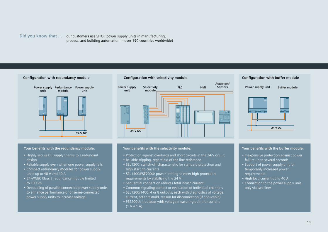
The SITOP selectivity modules are specifically tailored to switched-mode power supplies. The modules permit brief current peaks and switch off the electricity for longer over-loads, even on long, thin cables and with creeping short circuits in which the current is limited by the high ohmic resistance. In this case the circuit-breakers do not trip, or they trip too late, even if the power supply could deliver the current. The selectivity modules reliably disconnect the faulty load circuits, and the supply to the other loads con-tinues with absolutely no interruption so that total failure of the plant can be avoided. The affected feeder is indi-cated by an LED. The option with single-channel signaling also allows remote output-specific fault location. The new SEL1200 and SEL1400 four or eight-channel modules also have an interface with comprehensive diagnostics options for each output.
Safeguarding against failure through redundancy
Two power supply units can be connected via the SITOP redundancy module for additional failure safety. If one unit fails, the other automatically takes over the power supply function. Even in the event of a short circuit inside a power supply unit, the power supply remains reliable. Thanks to its high dielectric strength, the new RED1200 redundancy module also decouples power supplies without output voltages up to 48 V.
Buffer module bridges brief power failures
Although power failures usually last only a fraction of a second, they can cause costly and time-consuming damage. In combination with the 24-V power supply units, the buffer module bridges short-duration voltage dips with its electro-lyte capacitors.
Add-on modulesFor increasing system availability to all-round protection
12
Add-on-Module
Did you know that … our customers use SITOP power supply units in manufacturing, process, and building automation in over 190 countries worldwide?
Power supply unit
Power supply unit
Redundancy module
Configuration with redundancy module Configuration with selectivity module Configuration with buffer module
Power supply unit
Selectivity module
PLC HMIActuators/
Sensors
24 V DC24 V DC
Power supply unit
Buffer module
24 V DC
Your benefits with the redundancy module:
• Highly secure DC supply thanks to a redundant design
• Reliable supply even when one power supply fails• Compact redundancy modules for power supply
units up to 48 V and 40 A• 24-V/NEC Class 2 redundancy module limited
to 100 VA• Decoupling of parallel-connected power supply units
to enhance performance or of series-connected power supply units to increase voltage
Your benefits with the selectivity module:
• Protection against overloads and short circuits in the 24-V circuit• Reliable tripping, regardless of the line resistance• SEL1200: switch-off characteristic for standard protection and
high starting currents • SEL1400/PSE200U: power limiting to meet high protection
requirements by stabilizing the 24 V• Sequential connection reduces total inrush current • Common signaling contact or evaluation of individual channels• SEL1200/1400: 4 or 8 outputs, each with diagnostics of voltage,
current, set threshold, reason for disconnection (if applicable)• PSE200U: 4 outputs with voltage measuring point for current
(1 V ≙ 1 A)
Your benefits with the buffer module:
• Inexpensive protection against power failure up to several seconds
• Support of power supply unit for temporarily increased power requirements
• High load current up to 40 A• Connection to the power supply unit
only via two lines
13

No matter how many requirements a power supply must meet, SITOP always optimally
supports your planning process – from product selection and mechanical and electrical
design to project-specific plant documentation and engineering. With the TIA Selection
Tool, you can select your power supply, add-on modules, and DC UPS faster and order it directly.
In addition, you will automatically receive the required CAD data and circuit diagram macros.
And using the TIA portal, you can even simply and reliably parameterize and diagnose the modular
SITOP UPS8600 power supply system and the SITOP UPS1600 DC uninterruptible power supply.
Everything you need for planning
Additional information – including 3D data, circuit diagram macros according to IEC or ANSI, certificates, and operating instructions – are available at the click of a mouse. With the aid of the CAx Manager, you can download engineering data in the DXF, STEP, EPLAN, and eCl@ss advanced formats and apply it directly to your project engineering. Not only does this save you a significant amount of valuable engi-neering time, but you also benefit from the configurable manuals when creating custom project documentation using My Documentation Manager.
TIA Selection Tool: Power supply selection based on technical specifications
TIA Selection Tool: In the 24-V DC power consumer view, the necessary SITOP power supply can be easily selected for the chosen automation products.
CAD and CAE data in the image database for simple configuration
All product information is available per download via the CAx download manager.
Comprehensive support from planning to operation
Efficiency starts with selection
With just a few mouse clicks, the TIA Selection Tool guides you to the optimal power supply for your requirements. Simply enter the relevant parameters. If there are multiple solutions, an overview offers a comparison table containing several devices. Once you’ve opted for a power supply, you can easily select the appropriate redundancy, selectivity, and DC UPS modules. You can then export the resulting product configuration to various CAD, CAE, and engineering systems (like the TIA Portal) and continue to use it. With a single mouse click, you can transfer the selected products to the Industry Mall shopping cart and conveniently order them from there. The 24-V consumer view in the TIA Selection Tool helps you easily select the power supply for your project by automatically calculating the power requirements of the automation products to be supplied.
14

Convenient engineering in the TIA Portal
You can easily perform the engineering tasks for the SITOP PSU8600 power supply system and the SITOP UPS1600 uninterruptible power supply via the TIA Portal. Device selec-tion and network connection are a simple matter of drag-and-drop or copy-and-paste. In addition, function blocks for SIMATIC S7-300, 400, 1200, and 1500 are available for inte-grating the power supply system and DC UPS into STEP 7 user programs. There are also tailor-made faceplates to visualize the operational and diagnostic data using SIMATIC operating and monitoring systems. All of this helps reduce engineering effort and saves costs.
Your advantages through system integration of SITOP UPS1600 and SITOP PSU8600
• Time and cost savings during configuration and operation• Convenient engineering in the TIA portal• Quick product selection and network integration
in PROFINET• Comprehensive parameterization of devices• Comprehensive diagnostic options• Simple integration into STEP 7 user programs with function
blocks for S7-300/400/1200/1500• Fast integration into operation and monitoring with
faceplates for SIMATIC panels and SIMATIC WinCC
Integrating the SITOP UPS1600 DC UPS into PROFINET is easy and fail-safe via the TIA Portal.
Configuring and setting parameters for the PSU8600 power supply system in the TIA Portal is both intuitive and convenient.
Did you know that … SITOP PSU8600 and SITOP UPS1600 (version with IE/PN interface) have integrated Web servers that they can use for commissioning and remote diagnostics?
siemens.com/ tia-selection-tool
15

Did you know that … with the new SITOP Manager V1.1, you can configure and diagnose uninterruptible SITOP power supplies with a USB interface, which also includes SITOP UPS500 and predecessors of UPS1600?
The status of the communication-capable SITOP devices can be conveniently obtained via online diagnostics in the SITOP Manager. Here is the operating data for the SITOP UPS1600/UPS1100.
Optimal interoperability with different control systems: SITOP Manager –
the Windows software for the SITOP PSU8600 power supply system and
SITOP uninterruptible power supplies – is available free of charge.
SITOP Manager – the software for easy integration of SITOP PSU8600, UPS500, and UPS1600 in open systems
High performance for configuration
With the SITOP Manager software, all the power supplies in a network can be parameterized and diagnosed by a PC with the Windows 7 or 10 operating system. This is ideal, especially if plant configuration and programming isn’t performed via the TIA Portal or SIMATIC Step 7. Thanks to a user interface based on a Web browser, the application can also run on mobile terminals and automatically adapts the display size.
With the user-friendly SITOP Manager software, it’s easy to parameterize the SITOP PSU8600 power supply system and the SITOP uninterruptible power supplies – for example, to define output voltages and current thresholds or to safely shut down PCs in the event of a power failure.
Uncompromising when it comes to security
Communication between SITOP Manager and the con-nected power supplies is via the open, multi-vendor, Ethernet-based OPC UA communication standard. This standard meets extremely high security requirements for secure data transmission.
siemens.com/download-smgr
16

Our answers to your require-
ments with regard to a high-
performance power supply:
The selection of the power sup-ply unit is based on the input and output data. On the following two pages (pages 18 and 19), you will find a selection table with the available SITOP power supply units and the product lines to which they belong. The technical data is located on the subse-quent pages under the corre-sponding product line.But which product line is the right one for my application?As a decision-making aid, you can refer to the selection matrix containing the most important data, properties, functions, certificates, and expansion options for increasing 24-V availability.
Advanced power supplies Standard power supplies Basic power suppliesSITOP PSU8600 – power supply system with PROFINET and OPC UA
SITOP PSU8200 – The technology power supply for demanding solutions
SITOP PSU6200 – the all-around power supply for a wide range of applications
SITOP smart – The powerful standard power supply
SITOP lite – The costeffec-tive basic power supply
LOGO!Power – The flat power supply for distribution boards
Input/output Input AC/DC 1,3 1,2,3 = 1,3 = 1,3 1 1 =Rated power up to approx. P 960 W 960 W 480 W 960 W 480 W 100 W
Rated output voltages U 5–24 V DC 24/36/48 V DC 12/24/48 V DC 12/24 V DC 24 V DC 5/12/15/24 V DC
Rated output currents (24 V) I 20–40 A 5–40 A 1.3–20 A 2.5–40 A 2.5–20 A 0.6–4.0 A
Properties Overload behavior Pmax Extra Power Extra Power Power Boost Extra Power Extra Power
Extra power on startup
Energy efficiency +++ +++ +++ ++ + ++
Automation integration
DC o.k.Remote on/off
DC o.k.Diagnostics interface
DC o.k.
Safety, environment
Explosion protection: ATEX, IECEx, CCC, or FM
● ● ● ● ●
Marine approval: DNV GL or ABS
● ● in preparation ● ●
Ambient temperature range
–25 ... +60 °C –25 ... +70 °C –30 ... +70 °C –25 ... +70 °C 0 ... +60 °C –25 ... +70 °C
24-V power supply units expandable with …
Redundancy module ● ● ● ● ● ●
Selectivity module I > integrated ● ● ● ● ●
Buffer modules
integrated ● ● ● ● ●
DC UPS with Ultracaps min
integrated ● ● ● ● ●
DC UPS with batteries h
integrated ● ● ● ● ●
SITOP – the right power supply for every application
Selection matrix of the SITOP DIN rail power supply units according to performance data and range of functions
17

Selection table SITOP power suppliesInput voltage Output
currentAdvanced power supplies Standard power supplies Basic power supplies SIMATIC design SITOP DC/DC converter Special designs
SITOP PSU8600 SITOP PSU8200 SITOP PSU6200 SITOP smart SITOP lite LOGO!Power SITOP compactDC 24-V output voltage1-phase 120 V, 230 V AC
0.6 A 6EP3330-6SB00-0AY0 6EP1331-5BA001.3 A 6EP3331-7SB00-0AX0 6EP3331-6SB00-0AY0 6EP1331-5BA102 A 6ES7307-1BA01-0AA0 6EP1331-1LD002.5 A 6EP3332-7SB00-0AX0 6EP1332-2BA20 6EP1332-1LB00 6EP3332-6SB00-0AY0 6EP1332-5BA00 6EP1332-1SH713 A 6EP1332-4BA00 6EP1332-1LD003.5 A 6EP1332-1SH313.7 A 6EP3333-7LB00-0AX0 6EP1332-5BA204 A 6EP3333-6SB00-0AY0 6EP1332-5BA10 6EP1332-1LD105 A 6EP1333-3BA10 6EP3333-7SB00-0AX0 6EP1333-2BA20 6EP1333-1LB00 6ES7307-1EA01-0AA0 6EP1333-1AL12
6EP3333-8SB00-0AY0 6ES7307-1EA80-0AA0 6EP1333-7CA006EP7133-6AB00-0BN0
6.2 A 6EP1333-1LD008 A 6EP1333-4BA00 6EP1334-7CA0010 A 6EP1334-3BA10 6EP3334-7SB00-3AX0 6EP1334-2BA20 6EP1334-1LB00 6ES7307-1KA02-0AA0 6EP1334-1AL12
6EP3334-8SB00-0AY0 6EP1334-2AA01-0AB0 6EP7133-6AE00-0BN0 6EP3343-0SA00-0AY012.5 A 6EP1334-1LD0020 A 6EP1336-3BA10 6EP3336-7SB00-3AX0 6EP1336-2BA10 6EP1336-1LB0020 A/4 x 5 A 6EP3336-8MB00-2CY040 A 6EP3337-8SB00-0AY0
3-phase 400–500 V AC
5 A 6EP1333-3BA101) 6EP3433-7SB00-0AX0 6EP1433-2BA20 6EP1433-0AA008 A 6ES7148-4PC00-0HA0 6ES7148-4PC00-0HA010 A 6EP1334-3BA101) 6EP3434-7SB00-3AX0 6EP1434-2BA2017A 6EP3436-8UB00-0AY020 A 6EP3436-8SB00-0AY0 6EP3436-7SB00-3AX0 6EP1436-2BA10
6EP3436-8SB00-2AY020 A/ 4 x 5 A 6EP3436-8MB00-2CY0
30 A 6EP3437-8UB00-0AY040 A 6EP3437-8SB00-0AY0 6EP1437-2BA20 6EP3437-8UB00-0AY0
6EP3437-8SB00-2AY040 A/ 4 x 10 A 6EP3437-8MB00-2CY0
12 V DC 4 A 6EP3133-0TA10-0AY024–110 V DC 2 A 6ES7305-1BA80-0AA0 6EP1732-0AA0 (as of 48 V DC)24 V DC 5 A 6EP3133-0TA00-0AY0
10 A 6EP3134-0TA00-0AY0
48 V DC3,5 A 6EP3233-0TA10-0AY05 A 6EP3233-0TA00-0AY010 A 6EP3234-0TA00-0AY0
110–300 V DC120–240 V DC
0.6 A 6EP3330-6SB00-0AY0 6EP1331-5BA001.3 A 6EP3331-7SB00-0AX0 6EP3331-6SB00-0AY0 6EP1331-5BA102.5 A 6EP3332-7SB00-0AX0 6EP3332-6SB00-0AY0 6EP1332-5BA003.7 A 6EP3333-7LB00-0AX0 6EP1332-5BA204 A 6EP3333-6SB00-0AY0 6EP1332-5BA105 A 6EP3333-7SB00-0AX010 A 6EP3334-7SB00-3AX020 A 6EP3336-7SB00-3AX0
110–220 V DC 20 A/4 x 5 A 6EP3336-8MB00-2CY088–350 V DC 20 A 6EP1336-3BA10 6EP1336-1LB00600 V DC 20 A 6EP1536-3AA00
1) Connection to two phases 230–500 V AC – sheet 24/25, SITOP PSU200M 1-/2-phase Gray: more information in the Industry Mall
18

Input voltage Output current
Advanced power supplies Standard power supplies Basic power supplies SIMATIC design SITOP DC/DC converter Special designsSITOP PSU8600 SITOP PSU8200 SITOP PSU6200 SITOP smart SITOP lite LOGO!Power SITOP compact
DC 24-V output voltage1-phase 120 V, 230 V AC
0.6 A 6EP3330-6SB00-0AY0 6EP1331-5BA001.3 A 6EP3331-7SB00-0AX0 6EP3331-6SB00-0AY0 6EP1331-5BA102 A 6ES7307-1BA01-0AA0 6EP1331-1LD002.5 A 6EP3332-7SB00-0AX0 6EP1332-2BA20 6EP1332-1LB00 6EP3332-6SB00-0AY0 6EP1332-5BA00 6EP1332-1SH713 A 6EP1332-4BA00 6EP1332-1LD003.5 A 6EP1332-1SH313.7 A 6EP3333-7LB00-0AX0 6EP1332-5BA204 A 6EP3333-6SB00-0AY0 6EP1332-5BA10 6EP1332-1LD105 A 6EP1333-3BA10 6EP3333-7SB00-0AX0 6EP1333-2BA20 6EP1333-1LB00 6ES7307-1EA01-0AA0 6EP1333-1AL12
6EP3333-8SB00-0AY0 6ES7307-1EA80-0AA0 6EP1333-7CA006EP7133-6AB00-0BN0
6.2 A 6EP1333-1LD008 A 6EP1333-4BA00 6EP1334-7CA0010 A 6EP1334-3BA10 6EP3334-7SB00-3AX0 6EP1334-2BA20 6EP1334-1LB00 6ES7307-1KA02-0AA0 6EP1334-1AL12
6EP3334-8SB00-0AY0 6EP1334-2AA01-0AB0 6EP7133-6AE00-0BN0 6EP3343-0SA00-0AY012.5 A 6EP1334-1LD0020 A 6EP1336-3BA10 6EP3336-7SB00-3AX0 6EP1336-2BA10 6EP1336-1LB0020 A/4 x 5 A 6EP3336-8MB00-2CY040 A 6EP3337-8SB00-0AY0
3-phase 400–500 V AC
5 A 6EP1333-3BA101) 6EP3433-7SB00-0AX0 6EP1433-2BA20 6EP1433-0AA008 A 6ES7148-4PC00-0HA0 6ES7148-4PC00-0HA010 A 6EP1334-3BA101) 6EP3434-7SB00-3AX0 6EP1434-2BA2017A 6EP3436-8UB00-0AY020 A 6EP3436-8SB00-0AY0 6EP3436-7SB00-3AX0 6EP1436-2BA10
6EP3436-8SB00-2AY020 A/ 4 x 5 A 6EP3436-8MB00-2CY0
30 A 6EP3437-8UB00-0AY040 A 6EP3437-8SB00-0AY0 6EP1437-2BA20 6EP3437-8UB00-0AY0
6EP3437-8SB00-2AY040 A/ 4 x 10 A 6EP3437-8MB00-2CY0
12 V DC 4 A 6EP3133-0TA10-0AY024–110 V DC 2 A 6ES7305-1BA80-0AA0 6EP1732-0AA0 (as of 48 V DC)24 V DC 5 A 6EP3133-0TA00-0AY0
10 A 6EP3134-0TA00-0AY0
48 V DC3,5 A 6EP3233-0TA10-0AY05 A 6EP3233-0TA00-0AY010 A 6EP3234-0TA00-0AY0
110–300 V DC120–240 V DC
0.6 A 6EP3330-6SB00-0AY0 6EP1331-5BA001.3 A 6EP3331-7SB00-0AX0 6EP3331-6SB00-0AY0 6EP1331-5BA102.5 A 6EP3332-7SB00-0AX0 6EP3332-6SB00-0AY0 6EP1332-5BA003.7 A 6EP3333-7LB00-0AX0 6EP1332-5BA204 A 6EP3333-6SB00-0AY0 6EP1332-5BA105 A 6EP3333-7SB00-0AX010 A 6EP3334-7SB00-3AX020 A 6EP3336-7SB00-3AX0
110–220 V DC 20 A/4 x 5 A 6EP3336-8MB00-2CY088–350 V DC 20 A 6EP1336-3BA10 6EP1336-1LB00600 V DC 20 A 6EP1536-3AA00
1) Connection to two phases 230–500 V AC – sheet 24/25, SITOP PSU200M 1-/2-phase Gray: more information in the Industry Mall
Input voltage Output current Advanced power supplies Standard power supplies Basic power supplies SITOP DC/DC
converterSpecial designs
and applicationsSITOP PSU8600 SITOP PSU8200 SITOP PSU6200 SITOP smart LOGO!Power SITOP compact
Output voltage 5, 12, 15, 48, etc., V DC1-phase 120 V, 230 V AC
4–28 V/ 4 x 5 A 6EP3336-8SB00-2CY0
5 V/3 A 6EP3310-6SB00-0AY05 V/6.3 A 6EP3311-6SB00-0AY012 V/0.9 A 6EP3320-6SB00-0AY012 V/1.9 A 6EP3321-6SB00-0AY012 V/2.0 A 6EP3321-7SB00-0AX0 6EP1321-5BA0012 V/3.0 A 6EP1321-1LD0012 V/4.5 A 6EP3322-6SB00-0AY012 V/6.5 A 6EP1322-5BA1012 V/7 A 6EP3323-7SB00-0AX0 6EP1322-2BA0012 V/8.3 A 6EP1322-1LD0012 V/12 A 6EP3324-7SB00-3AX012 V/14 A 6EP1323-2BA0015 V/1.9 A 6EP3321-6SB10-0AY015 V/4 A 6EP3322-6SB10-0AY048 V/5 A 6EP3344-7SB00-3AX0 6EP3344-0SB00-0AY03–52 V/ 2–10 A 6EP3343-0SA00-0AY0
2 x 15 V/ 3.5 A 6EP3323-0SA00-0BY0
24 V DC 12 V/2.5 A 6EP1621-2BA0012 V/8 A 6EP3123-0TA00-0AY012 V/15 A 6EP3124-0TA00-0AY0
3-phase 400–500 V AC
4–28 V/20 A 6EP3436-8SB00-2CY04–28 V/ 4 x 5 A
6EP3436-8MB00-2CY0
4–28 V/ 40 A
6EP3437-8SB00-2CY0
4–28 V/ 4 x 10 A
6EP3437-8MB00-2CY0
12 V/20 A 6EP3424-8UB00-0AY036 V/13 A 6EP3446-8SB10-0AY048 V/10 A 6EP3446-8SB00-0AY048 V/20 A 6EP3447-8SB00-0AY0
19

Technical data SITOP PSU8600 1- and 2-phase1) basic unit, 4 outputs
SITOP PSU8600 3-phase basic unit, 1 output
SITOP PSU8600 3-phase basic unit, 4 outputs
SITOP PSU8600 3-phase basic unit, 4 outputs
Output voltage/current, type 24 V/20 A/4x5 A, PSU8600 24 V/20 A, PSU8600 24 V/40 A, PSU8600 24 V/20 A/4x5 A, PSU8600 24 V/40 A/4x10 A, PSU8600Article No. 6EP3336-8MB00-2CY0 6EP3436-8SB00-2AY0 6EP3437-8SB00-2AY0 6EP3436-8MB00-2CY0 6EP3437-8MB00-2CY0Rated input voltage 100-240 V AC, 110-220 V DC 400–500 V 3 AC 400–500 V 3 AC 400–500 V 3 AC 400–500 V 3 AC
– Range 85...275 V AC, 93...275 V DC 320…575 V 3 AC 320…575 V 3 AC 320…575 V 3 AC 320…575 V 3 AC Mains buffering > 20 ms (at 100 V), extendable via buffer mod-
ule or UPS module> 15 ms (at 400 V), extendable via buffer modules and UPS module
Rated line frequency 50/60 Hz 50/60 Hz 50/60 Hz 50/60 Hz 50/60 HzRated input current 5.4–2.4 A, 4.8–2.4 A 1.4–1.1 A 2.75–2.2 A 1.4–1.1 A 2.75–2.2 A
– Inrush current < 15 A < 14 A < 14 A < 14 A < 14 A – Recommended protection 10–32 A character C or time-lag fuses 6–16 A charact. C 3-ph. coupled or 3RV2011-1DA10 (setting 3 A) or 3RV2711-1DD10
Rated output voltage 24 V DC 24 V DC 24 V DC 24 V DC 24 V DC – Tolerance ± 3% ± 3 % ± 3 % ± 3 % ± 3 % – Setting range 4…28 V DC 4…28 V DC 4…28 V DC 4…28 V DC 4…28 V DC – Rated output current 20 A, 4 outputs each with 5 A, number
expandable via CNX modules20 A, one output, number can be increased via CNX module
40 A, one output, number can be increased via CNX module
20 A, four outputs at 5 A each, num-ber can be increased via CNX module
40 A, four outputs at 10 A each, number can be increased via CNX module
– Overload behavior (Extra Power) 30 A for 5 s/min 30 A for 5 s/min 60 A for 5 s/min 30 A for 5 s/min 60 A for 5 s/min – Derating - From +50 °C (2.5%/K); no derating in connection with expansion module and total load of basic devices’ ouput up to 240 W (20-A devices) or
up to 480 W (40-A devices)Switching threshold adjustment range 0.5…5 A 2…20 A 4…40 A 0.5…5 A 0.5…10 AShutdown behavior per output Load current 101...149 % of the setting: shutdown after 5 s; load current >150 % of the setting: Current limitation and shutdown after 200 msEfficiency at rated values, approx. 92% 93 % 94 % 93 % 94 %Signaling contact “DC o. k.” Yes Yes Yes Yes YesInterface Industrial Ethernet/PROFINET with two portsParallel switching Yes, output 1 with 2 or 3 with 4 Yes Yes Yes, output 1 with 2 or 3 with 4 Yes, output 1 with 2 or 3 with 4Radio interference suppression (EN 55022) Class B Class B Class B Class B Class BLine harmonics limitation (EN 61000-3-2) Yes Yes Yes Yes YesDegree of protection (EN 60529) IP 20 IP20 IP20 IP20 IP20Ambient temperature –25…+60 °C –25…+60 °C –25…+60 °C –25…+60 °C –25…+60 °CDimensions (W x H x D) in mm 125 x 125 x 150 80 x 125 x 150 125 x 125 x 150 100 x 125 x 150 125 x 125 x 150Weight approx. 2.65 kg 1.8 kg 2.65 kg 2.0 kg 2.65 kgCertification CE, cULus, CB, cCSAus, IECEx, ATEX, CCC
(further in preparation))CE, cULus, CB, cCSAus, IECEx, ATEX, CCC, cCSAus Class I Div 2, SEMI F47, DNV GL, ABS
System expandability Up to 4 expansion modules (CNX8600) and up to 2 buffer components (BUF8600, UPS8600)
SITOP PSU8600 advanced power supplies The power supply system for digitalization and industry 4.0
20

Technical data SITOP PSU8600 1- and 2-phase1) basic unit, 4 outputs
SITOP PSU8600 3-phase basic unit, 1 output
SITOP PSU8600 3-phase basic unit, 4 outputs
SITOP PSU8600 3-phase basic unit, 4 outputs
Output voltage/current, type 24 V/20 A/4x5 A, PSU8600 24 V/20 A, PSU8600 24 V/40 A, PSU8600 24 V/20 A/4x5 A, PSU8600 24 V/40 A/4x10 A, PSU8600Article No. 6EP3336-8MB00-2CY0 6EP3436-8SB00-2AY0 6EP3437-8SB00-2AY0 6EP3436-8MB00-2CY0 6EP3437-8MB00-2CY0Rated input voltage 100-240 V AC, 110-220 V DC 400–500 V 3 AC 400–500 V 3 AC 400–500 V 3 AC 400–500 V 3 AC
– Range 85...275 V AC, 93...275 V DC 320…575 V 3 AC 320…575 V 3 AC 320…575 V 3 AC 320…575 V 3 AC Mains buffering > 20 ms (at 100 V), extendable via buffer mod-
ule or UPS module> 15 ms (at 400 V), extendable via buffer modules and UPS module
Rated line frequency 50/60 Hz 50/60 Hz 50/60 Hz 50/60 Hz 50/60 HzRated input current 5.4–2.4 A, 4.8–2.4 A 1.4–1.1 A 2.75–2.2 A 1.4–1.1 A 2.75–2.2 A
– Inrush current < 15 A < 14 A < 14 A < 14 A < 14 A – Recommended protection 10–32 A character C or time-lag fuses 6–16 A charact. C 3-ph. coupled or 3RV2011-1DA10 (setting 3 A) or 3RV2711-1DD10
Rated output voltage 24 V DC 24 V DC 24 V DC 24 V DC 24 V DC – Tolerance ± 3% ± 3 % ± 3 % ± 3 % ± 3 % – Setting range 4…28 V DC 4…28 V DC 4…28 V DC 4…28 V DC 4…28 V DC – Rated output current 20 A, 4 outputs each with 5 A, number
expandable via CNX modules20 A, one output, number can be increased via CNX module
40 A, one output, number can be increased via CNX module
20 A, four outputs at 5 A each, num-ber can be increased via CNX module
40 A, four outputs at 10 A each, number can be increased via CNX module
– Overload behavior (Extra Power) 30 A for 5 s/min 30 A for 5 s/min 60 A for 5 s/min 30 A for 5 s/min 60 A for 5 s/min – Derating - From +50 °C (2.5%/K); no derating in connection with expansion module and total load of basic devices’ ouput up to 240 W (20-A devices) or
up to 480 W (40-A devices)Switching threshold adjustment range 0.5…5 A 2…20 A 4…40 A 0.5…5 A 0.5…10 AShutdown behavior per output Load current 101...149 % of the setting: shutdown after 5 s; load current >150 % of the setting: Current limitation and shutdown after 200 msEfficiency at rated values, approx. 92% 93 % 94 % 93 % 94 %Signaling contact “DC o. k.” Yes Yes Yes Yes YesInterface Industrial Ethernet/PROFINET with two portsParallel switching Yes, output 1 with 2 or 3 with 4 Yes Yes Yes, output 1 with 2 or 3 with 4 Yes, output 1 with 2 or 3 with 4Radio interference suppression (EN 55022) Class B Class B Class B Class B Class BLine harmonics limitation (EN 61000-3-2) Yes Yes Yes Yes YesDegree of protection (EN 60529) IP 20 IP20 IP20 IP20 IP20Ambient temperature –25…+60 °C –25…+60 °C –25…+60 °C –25…+60 °C –25…+60 °CDimensions (W x H x D) in mm 125 x 125 x 150 80 x 125 x 150 125 x 125 x 150 100 x 125 x 150 125 x 125 x 150Weight approx. 2.65 kg 1.8 kg 2.65 kg 2.0 kg 2.65 kgCertification CE, cULus, CB, cCSAus, IECEx, ATEX, CCC
(further in preparation))CE, cULus, CB, cCSAus, IECEx, ATEX, CCC, cCSAus Class I Div 2, SEMI F47, DNV GL, ABS
System expandability Up to 4 expansion modules (CNX8600) and up to 2 buffer components (BUF8600, UPS8600)
Technical data Expansion moduleOutput current, typ 4 x 5 A, CNX8600 4 x 10 A, CNX8600 8 x 2.5 A, CNX8600Article No. 6EP4436-8XB00-0CY0 6EP4437-8XB00-0CY0 6EP4436-8XB00-0DY0Product/function description Expansion module for PSU8600 basic devices for distribution of the direct current to other load circuits
and monitoring for overload; selective switch-off of defective circuits, switching threshold individually configurable; a total of four modules can be used in a group of systems; data and power are transmitted via the System Clip Link connector
Rated output voltage 24 V DC 24 V DC 24 V DC – Tolerance ± 3 % ± 3 % ± 3 % – Setting range 4…28 V DC 4…28 V DC 4…28 V DC
Rated output current 20 A/4 outputs of 5 A each 40 A/4 outputs of 10 A each 20 A/8 outputs of 2.5 A eachComment: The max. output capacity of the overall PSU8600 system cannot be increased via expansion modules
– Switching threshold adjustment range 0.5…5 A 0.5…10 A 0.5...2.5 A – Shutdown behavior per output Load current 101...149 % of the setting: shutdown after 5 s; load current >150 % of the setting:
Current limitation and shutdown after 200 msDegree of protection (EN 60529) IP 20 IP 20 IP 20Ambient temperature –25…+60 °C –25…+60 °C –25…+60 °CDimensions (W x H x D) in mm 60 x 125 x 150 60 x 125 x 150 100 x 125 x 150Weight approx. 1.15 kg 1.15 kg 1.29 kgCertification CE, cULus, CB, cCSAus, IECEx, ATEX, CCC, cCSAus Class I Div 2, SEMI F47, DNV GL, ABS,
6EP4436-8XB00-0DY0: NEC Class 2
1) 2-phase connection to 240 V, e.g. in North America Specifications at rated input voltage and ambient temperature at +25 °C (unless otherwise specified)
21

SITOP PSU8600 advanced power supplies The power supply system for digitalization and industry 4.0
Technical data Buffer moduleBuffer time, type 100 ms/40 A, BUF8600 300 ms/40 A, BUF8600 4 s/40 A, BUF8600 10 s/40 A, BUF8600Article No. 6EP4297-8HB00-0XY0 6EP4297-8HB10-0XY0 6EP4293-8HB00-0XY0 6EP4295-8HB00-0XY0Product/function description
Expansion module for PSU8600 basic devices to extend buffering time during power failures. A total of two buffer components (BUF8600, UPS8600) can be used in a group of systems. Data and power are transmitted via the System Clip Link connector.
Internal energy storage Electrolytic capacitors Double-layer capacitors (Ultracaps)Buffer time with 24 V DC and load current5 A 800 ms 2.4 s 40 s 80 s10 A 400 ms 1.2 s 20 s 40 s20 A 200 ms 600 ms 10 s 20 s40 A 100 ms 300 ms 4 s 10 sTypical charging time 19 s 54 s 5 min 10 minMax. power during buffer operation 60 A for 5 s/min 60 A for 5 s/min 40 A 60 A for 5 s/minStatus messages via 3-color LED Normal operation, state of charge, buffer operation, error Normal operation, state of charge, buffer operation, errorStatus messages via signal contact
– State of charge > x %, buffer operation
Status messages via PROFINET (basic unit) Normal operation, state of charge, buffer operation, error Normal operation, state of charge, buffer operation, errorAdditional functions _ Remote on/off contact for deactivating buffering, e.g., when shutting down the
plant to prevent unnecessary discharge
Degree of protection (EN 60529) IP 20 IP 20 IP 20 IP 20Ambient temperature –25…+60 °C –25…+60 °C –25…+60 °C –25…+60 °CDimensions (W x H x D) in mm 60 x 125 x 150 125 x 125 x 150 60 x 125 x 150 125 x 125 x 150Weight approx. 1.33 kg 2.26 kg 1.25 kg 1.95 kgCertification CE, cULus, CB, cCSAus, IECEx, ATEX, CCC, cCSAus Class I Div 2, SEMI F47, DNV GL, ABS CE, cULus, CB, cCSAus, IECEx, ATEX, CCC, cCSAus Class I Div 2, SEMI F47, DNV GL, ABs
Specifications at rated input voltage and ambient temperature at +25 °C (unless otherwise specified)
22
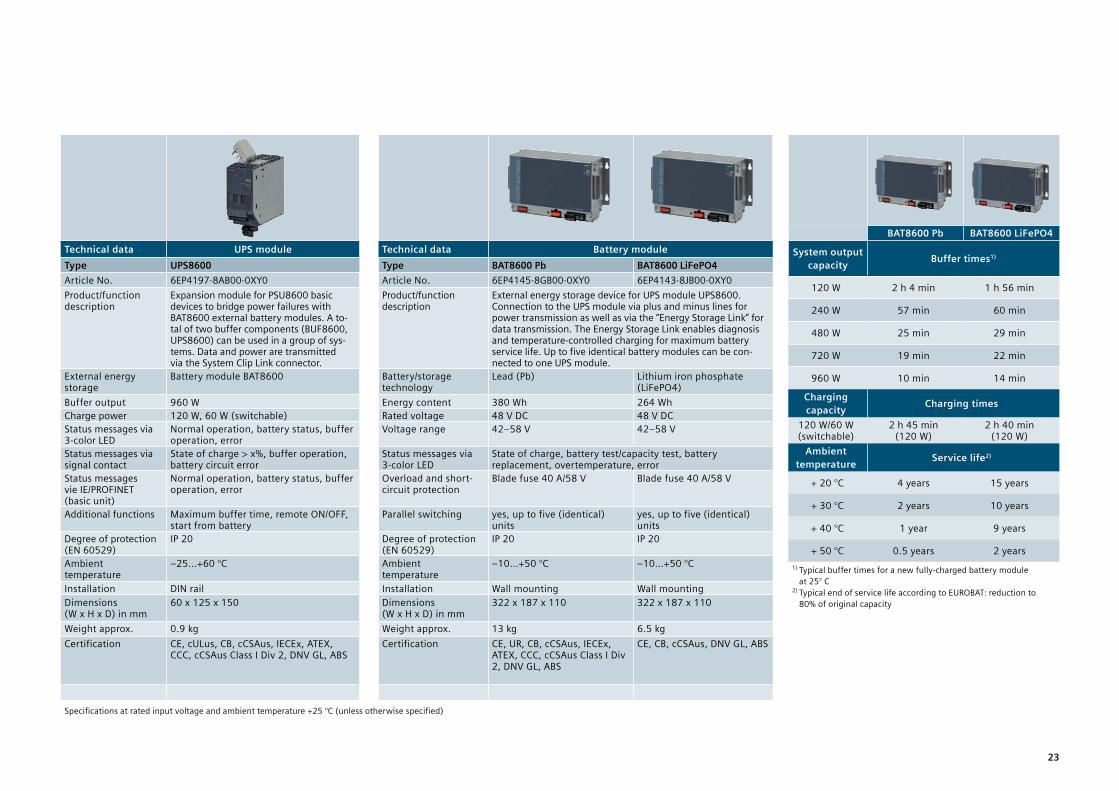
Technical data UPS module Technical data Battery moduleType UPS8600 Type BAT8600 Pb BAT8600 LiFePO4Article No. 6EP4197-8AB00-0XY0 Article No. 6EP4145-8GB00-0XY0 6EP4143-8JB00-0XY0Product/function description
Expansion module for PSU8600 basic devices to bridge power failures with BAT8600 external battery modules. A to- tal of two buffer components (BUF8600, UPS8600) can be used in a group of sys-tems. Data and power are transmitted via the System Clip Link connector.
Product/function description
External energy storage device for UPS module UPS8600. Connection to the UPS module via plus and minus lines for power transmission as well as via the “Energy Storage Link” for data transmission. The Energy Storage Link enables diagnosis and temperature-controlled charging for maximum battery service life. Up to five identical battery modules can be con-nected to one UPS module.
External energy storage
Battery module BAT8600 Battery/storage technology
Lead (Pb) Lithium iron phosphate (LiFePO4)
Buffer output 960 W Energy content 380 Wh 264 WhCharge power 120 W, 60 W (switchable) Rated voltage 48 V DC 48 V DCStatus messages via 3-color LED
Normal operation, battery status, buffer operation, error
Voltage range 42–58 V 42–58 V
Status messages via signal contact
State of charge > x%, buffer operation, battery circuit error
Status messages via 3-color LED
State of charge, battery test/capacity test, battery replacement, overtemperature, error
Status messages vie IE/PROFINET (basic unit)
Normal operation, battery status, buffer operation, error
Overload and short-circuit protection
Blade fuse 40 A/58 V Blade fuse 40 A/58 V
Additional functions Maximum buffer time, remote ON/OFF, start from battery
Parallel switching yes, up to five (identical) units
yes, up to five (identical) units
Degree of protection (EN 60529)
IP 20 Degree of protection (EN 60529)
IP 20 IP 20
Ambient temperature
–25…+60 °C Ambient temperature
–10…+50 °C –10…+50 °C
Installation DIN rail Installation Wall mounting Wall mountingDimensions (W x H x D) in mm
60 x 125 x 150 Dimensions (W x H x D) in mm
322 x 187 x 110 322 x 187 x 110
Weight approx. 0.9 kg Weight approx. 13 kg 6.5 kgCertification CE, cULus, CB, cCSAus, IECEx, ATEX,
CCC, cCSAus Class I Div 2, DNV GL, ABSCertification CE, UR, CB, cCSAus, IECEx,
ATEX, CCC, cCSAus Class I Div 2, DNV GL, ABS
CE, CB, cCSAus, DNV GL, ABS
Specifications at rated input voltage and ambient temperature +25 °C (unless otherwise specified)
BAT8600 Pb BAT8600 LiFePO4
System output capacity Buffer times1)
120 W 2 h 4 min 1 h 56 min
240 W 57 min 60 min
480 W 25 min 29 min
720 W 19 min 22 min
960 W 10 min 14 min
Charging capacity Charging times
120 W/60 W (switchable)
2 h 45 min (120 W)
2 h 40 min (120 W)
Ambient temperature Service life2)
+ 20 °C 4 years 15 years
+ 30 °C 2 years 10 years
+ 40 °C 1 year 9 years
+ 50 °C 0.5 years 2 years1) Typical buffer times for a new fully-charged battery module
at 25° C2) Typical end of service life according to EUROBAT: reduction to
80% of original capacity
23

SITOP PSU8200 advanced power supplies Technology power supply for demanding applications
Technical data SITOP PSU8200 1-phase SITOP PSU200M 1-phase/2-phase2)
Output voltage/current, type 24 V/5 A, PSU8200 24 V/10 A, PSU8200 24 V/20 A, PSU8200 24 V/40 A, PSU8200 24 V/5 A, PSU200MArticle No. 6EP3333-8SB00-0AY0 6EP3334-8SB00-0AY0 6EP1336-3BA10 6EP3337-8SB00-0AY0 6EP1333-3BA10Rated input voltage
– Range120–230 V AC 85…132/170…264 V AC, automatic range switching
120–230 V AC 85…275 V AC or 88…350 V DC
120/230 V AC 85...132/170...264 V AC, automatic range switching
120–230/230–500 V AC 85…264/176…550 V AC
Mains buffering > 35 ms (at 120/230 V) > 35 ms (at 120/230 V) > 20 ms (at 120/230 V) > 25 ms (at 230 V) > 25 ms (at 120/230 V)Rated line frequency 50/60 Hz 50/60 Hz 50/60 Hz 50/60 Hz 50/60 HzRated input current
– Inrush current1)
– Recommended miniature circuit breaker
2.1/1.2 A< 10 A6 A charact. Cor 3RV1021-1xA10
4.0/1.9 A< 10 A10 A charact. Cor 3RV1021-1xA10
4.6–2.5 A < 20 A 10 A charact. C or 3RV1021-1xA10
15.0/8.0 A < 50 A 20 A charact. C or 3RV2411-xxA10
2.2–1.2/1.2–0.61 A < 35 A 6 A charact. C or 3RV2011 -1xA10
Rated output voltage – Tolerance – Setting range
24 V DC ± 3 % 24…28.8 V DC
24 V DC ± 3 % 24…28.8 V DC
24 V DC ± 3 % 24…28.8 V DC
24 V DC ± 3 % 24…28.8 V DC
24 V DC ± 3 % 24…28.8 V DC
Rated output current 5 A 10 A 20 A 40 A 5 A – Overload behavior (power boost for 25 ms)
15 A 30 A 60 A 120 A 15 A
– Overload behavior (extra power for 5 s/min)
7.5 A 15 A 30 A 60 A No
– Derating - from +60 °C (2 %/K) from +60 °C (3 %/K) from +60 °C (2.5 %/K) from +60 °C (2 %/K)Efficiency at rated values, approx. 93 % 94 % 93 % 92 % 88 %Signaling contact “DC o. k.” Yes Yes Yes Yes YesRemote On/Off Yes Yes No No NoParallel switching Yes, output characteristic can be switched to parallel operationElectronic short-circuit protection Yes, constant current or latching shutdown selectable; constant current: approx. 1.15 x rated output currentRadio interference suppression (EN 55022)
Class B Class B Class B Class B Class B
Supply harmonics limitation yes (EN 61000-3-2) yes (EN 61000-3-2) yes (EN 61000-3-2) yes (EN 61000-3-2) yes (EN 61000-3-2)Degree of protection (EN 60529) IP20 IP20 IP20 IP20 IP20Ambient temperature –25…+70 °C –25…+70 °C –25…+70 °C –25…+70 °C –25…+70 °CDimensions (W x H x D) in mm 45 x 125 x 125 55 x 125 x 125 90 x 125 x 125 145 x 145 x 150 70 x 125 x 121Weight approx. 0.8 kg 1 kg 1.5 kg 3.1 kg 0.6 kgCertification CE, cULus, CB, ATEX, IECEx, CCC, cCSAus Class I Div 2, SEMI F473),
DNV GL, ABSCE, cULus, ATEX, IECEx, CCC, UL Class I Div 2, DNV GL, ABS
CE, cULus, CB, ATEX, IECEx, CCC, cCSAus Class I Div 2, SEMI F474), DNV GL, ABS
CE, cULus, CB, ATEX, IECEx, CCC, UL Class I Div 2, SEMI F473), DNV GL, ABS
1) Inrush current can be limited by using a SITOP inrush current limiter: 6EP4683-6LB00-0AY0 (max. 5 A, 100–240 V AC) or 6EP1967-2AA00 (max. 10 A, 100–480 V AC, 1 unit per phase required). 2) Connection to two phases of a three-phase supply network 3) At an input voltage of 208–230 V AC 4) In combination with two buffer modules. Technical data applies at rated input voltage and ambient temperature of +25°C (unless otherwise specified).24

SITOP PSU200M 1-phase/2-phase2) SITOP PSU8200 3-phase SITOP PSU8200 3-phase, 36 V SITOP PSU8200 3-phase, 48 V24 V/10 A, PSU200M 24 V/20 A, PSU8200 24 V/40 A, PSU8200 36 V/13 A, PSU8200 48 V/10 A, PSU8200 48 V/20 A, PSU82006EP1334-3BA10 6EP3436-8SB00-0AY0 6EP3437-8SB00-0AY0 6EP3446-8SB10-0AY0 6EP3446-8SB00-0AY0 6EP3447-8SB00-0AY04)
120–230/230–500 V AC 85…264/176…550 V AC
400–500 V 3 AC 320…575 V 3 AC
400–500 V 3 AC 320…575 V 3 AC
400–500 V 3 AC 320…575 V 3 AC
400–500 V 3 AC 320…575 V 3 AC
400–500 V 3 AC 320...575 V 3 AC
> 25 ms (at 120/230 V) > 15 ms (at 400 V) > 10 ms (at 400 V) > 15 ms (at 400 V) > 15 ms (at 400 V) > 10 ms (at 400 V)50/60 Hz 50/60 Hz 50/60 Hz 50/60 Hz 50/60 Hz 50/60 Hz4.4–2.4/2.4–1.1 A < 35 A 6 A charact. C or 3RV2011-1xA10
1.2–1.0 A < 18 A 6–16 A charact. C 3-ph. coupled or 3RV2011-1DA10 or 3RV2711-1DD10
2.1–1.7 A < 13 A 10–16 A charact. C 3-ph. coupled or 3RV2011-1DA10 or 3RV2711-1DD10
1.2–1.0 A < 18 A 6–16 A charact. C 3-ph. coupled or 3RV2011-1DA10 or 3RV2711-1DD10
1.2–1.0 A < 18 A 6 –16 A charact. C 3-ph. coupled or 3RV2011-1DA10 or 3RV2711-1DD10
2–1.7 A < 13 A 10 –16 A charact. C 3-ph. coupled or 3RV2011-1DA10 or 3RV2711-1DD10
24 V DC ± 3 % 24…28.8 V DC
24 V DC ± 3 % 24...28.8 V DC
24 V DC ± 3 % 24...28 V DC
36 V DC ± 3 % 32...40 V DC
48 V DC ± 3 % 42…56 V DC
48 V DC ± 3 % 46…56 V DC
10 A 20 A 40 A 13 A 10 A 20 A30 A 60 A 120 A 39 A 23 A 60 A
No 30 A 60 A 19.5 A 15 A 30 A
from +60 °C (2 %/K) from +60 °C (3 %/K) from +60 °C (4 %/K) from +60 °C (3 %/K) from +60 °C (3 %/K) from +60 °C (4 %/K)91 % 94 % 94 % 94 % 93 % 94 %Yes Yes Yes Yes Yes YesNo Yes Yes Yes Yes YesYes, output characteristic can be switched to parallel operationYes, constant current or latching shutdown selectable; constant current: approx. 1.15 x rated output currentClass B Class B Class B Class B Class B Class B
yes (EN 61000-3-2) yes (EN 61000-3-2) yes (EN 61000-3-2) yes (EN 61000-3-2) yes (EN 61000-3-2) yes (EN 61000-3-2) IP20 IP20 IP20 IP20 IP20 IP20–25…+70 °C –25…+70 °C –25…+70 °C –10…+70 °C –25...+70 °C –25...+70 °C70 x 125 x 121 70 x 125 x 125 135 x 145 x 150 70 x 125 x 125 70 x 125 x 125 135 x 145 x 1501.4 kg 1.2 kg 3.3 kg 1.2 kg 1.2 kg 3.3 kgCE, cULus, CB, ATEX, IECEx, CCC, UL Class I Div 2, SEMI F473), DNV GL, ABS
CE, cULus, CB, ATEX, IECEx, CCC, UL Class I Div 2, SEMI F47, DNV GL, ABS
CE; cULus, CB, ATEX, IECEx, CCC, cCSAus Class I Div 2, SEMI F47, DNV GL, ABS
CE, cULus, CB, CCC, cCSAus Class I Div 2
CE, cULus, CB, ATEX, IECEx, CCC, cCSAus Class I Div 2, DNV GL, ABS
CE, cULus, CB, ATEX, IECEx, CCC, cCSAus Class I Div 2, SEMI F47
25

New: SITOP PSU6200 standard power supplies The all-around power supply for a wide range of applications
Technical data SITOP PSU6200 1-phaseOutput voltage/current, type 12 V/2 A, PSU6200 24 V/1.3 A, PSU6200 24 V/2,5 A, PSU6200 12 V/7 A, PSU6200 24 V/3,7 A, PSU6200 24 V/5 A, PSU6200Article No. Article No. Ex version
6EP3321-7SB00-0AX0 6EP3331-7SB00-0AX0 6EP3332-7SB00-0AX0 6EP3323-7SB00-0AX0 6EP3333-7LB00-0AX0 6EP3333-7SB00-0AX0 6EP3333-7SC00-0AX0
Rated input voltage 120–230 V AC/120–240 V DC 120–230 V AC/120–240 V DC – Range 85–264 V AC/110–275 V DC 85–264 V AC/99–275 V DC
Mains buffering 150 ms at Uin = 230 V 150 ms at Uin = 230 V 150 ms at Uin = 230 V 90 ms at Uin = 230 V 90 ms at Uin = 230 V 80 ms at Uin = 230 VRated line frequency 50/60 Hz 50/60 Hz 50/60 Hz 50/60 Hz 50/60 Hz 50/60 HzRated input current 0.5/0.3 A 0.6/0.3 A 1.1/0.6 A 1.4/0.8 A 1.5/0.9 A 1.9/1.1 A
– Inrush current1) < 32 A < 32 A < 32 A < 29 A < 29 A < 29 A – Recom. miniature circuit breaker from 6 A characteristic C from 6 A characteristic C from 6 A characteristic C from 6 A characteristic C from 6 A characteristic C from 6 A characteristic C
Rated output voltage 12 V 24 V 24 V 12 V 24 V 24 V – Tolerance ± 3% ± 3% ± 3% ± 3% ± 3% ± 3% – Setting range 10.5–12.9 V 22.2–26.4 V 22.2–26.4 V 12–15.5 V 24–28 V 24–28 V
Rated output current 2 A 1.3 A 2.5 A 7 A 3.7 A 5 A – Permanently up to +45 °C 2 A 1.3 A 2.5 A 8.4 A 3.7 A 6 A – Overload behavior (extra power for 5 s/min)
– – – 150% – 150%
– Derating – from +60 °C (2.5%/K) from +60 °C (1.5%/K) from +60 °C (2%/K) – from +60 °C (2%/K)Efficiency at rated values, approx. 83.3% 86.3% 89% 87.1% 89.3% 90.2%Signaling contact No No No DC o.k. DC o.k. DC o.k.Parallel switching No No No No No NoElectronic short-circuit protection Yes, restart Yes, restart Yes, restart Yes, constant current
(< 9 V hiccup)Yes, constant current (< 15 V hiccup)
Yes, constant current (< 15 V hiccup)
Radio interfer. suppression (EN 55022) Class B Class B Class B Class B Class B Class BSupply harmonics limitation (EN 61000-3-2)
Not applicable Not applicable Not applicable Yes Yes Yes
Degree of protection (EN 60529) IP 20 IP 20 IP 20 IP 20 IP 20 IP 20Ambient temperature Operation –25...+70 °C Operation –30 ... +70 °C, startup starting from –40°CDimensions (W x H x D) in mm 25 x 100 x 88 25 x 100 x 88 40 x 100 x 88 35 x 135 x 125 35 x 135 x 125 35 x 135 x 125 Weight approx. 0.2 kg 0.2 kg 0.25 kg 0.7 kg 0.7 kg 0.7 kgCertification CE, cULus, cCSAus, CB, SEMI F47, in preparation: DNV GL, ABS. NEC Class 2: 12 V/2 A, 24 V/1.3 A; 2.5 A. NEC Class 2: 3.7 A. ATEX, IECEx, CCC: 6EP3333-7SC00-0AX0
1) Inrush current can be limited by means of a SITOP inrush current limiter: Article no. 6EP4683-6LB00-0AY0 (max. 5 A, 100–240 V AC) or 6EP1967-2AA00 (max. 10 A, 100–480 V AC) 1 unit per phase required 2) or 3RV2011-1EA10 or 3RV2711-1ED10
Technical data applies at rated input voltage and ambient temperature of +25°C (unless otherwise specified)
New: Ex version
26

SITOP PSU6200 1-phase SITOP PSU6200 3-phase12 V/12 A, PSU6200 24 V/10 A, PSU6200 48 V/5 A, PSU6200 24 V/20 A, PSU6200 24 V/5 A, PSU6200 24 V/10 A, PSU6200 24 V/20 A, PSU62006EP3324-7SB00-3AX0 6EP3334-7SB00-3AX0
6EP3334-7SC00-3AX06EP3344-7SB00-3AX0 6EP3336-7SB00-3AX0
6EP3336-7SC00-3AX06EP3433-7SB00-0AX0 6EP3434-7SB00-3AX0 6EP3436-7SB00-3AX0
120–230 V AC/110–240 V DC 400–500 V 3 AC85–264 V AC/85–275 V DC 323 ... 576 V 3 AC/450...600 V DC 70 ms at Uin = 230 V 45 ms at Uin = 230 V 46 ms at Uin = 230 V 25 ms at Uin = 230 V 20 ms at Uin = 400 V 30 ms at Uin = 400 V 25 ms at Uin = 400 V50/60 Hz 50/60 Hz 50/60 Hz 50/60 Hz 50/60 Hz 50/60 Hz 50/60 Hz1.4/0.8 A 2.2/1.2 A 2.2/1.2 A 4.3/2.3 A 0.33/0.28 A 0.39/0.32 A 0.77/0.62 A< 6 A < 6 A < 6 A < 12 A < 22 A < 13 A < 17 Afrom 6 A characteristic C from 10 A characteristic C from 10 A characteristic C from 10 A characteristic C 4...10 A char. C 3-ph. coupled2) 4...16 A characteristic C 3-ph. coupled2)
12 V 24 V 48 V 24 V 24 V 24 V 24 V± 3% ± 3% ± 3% ± 3% ± 3% ± 3% ± 3%12–15.5 V 24–28 V 48–56 V 24–28 V 24–28 V 24–28 V 24–28 V12 A 10 A 5 A 20 A 5 A 10 A 20 A14.4 A 12 A 6 A 24 A 6 A 12 A 24 A150% 150% 150% 150% 150% 150% 150%
from +60 °C (2%/K) from +60 °C (2%/K) from +60 °C (3%/K) from +60 °C (1%/K) from +60 °C (3%/K) from +60 °C (3%/K) from +60 °C (3%/K)89.3% 92.8% 93.9% 95.5% 91.2% 95.4% 95.9%DC o.k./Diagnose DC o.k./Diagnose DC o.k./Diagnose DC o.k./Diagnose DC o.k. DC o.k./Diagnose DC o.k./DiagnoseYes, 2 units Yes, 2 units Yes, 2 units Yes, 2 units No Yes, 2 units Yes, 2 unitsYes, constant current (< 9 V hiccup)
Yes, constant current (< 15 V hiccup)
Yes, constant current (< 30 V hiccup)
Yes, constant current (< 15 V hiccup)
Yes, constant current (< 15 V hiccup)
Yes, constant current (< 15 V hiccup)
Yes, constant current (< 15 V hiccup)
Class B Class B Class B Class B Class B Class B Class BYes Yes yes Yes Yes Yes Yes
IP 20 IP 20 IP 20 IP 20 IP 20 IP 20 IP 20–25...+70 °C, startup starting from –40 °C
Operation –30 ... +70 °C, startup starting from –40°C
45 x 135 x 125 45 x 135 x 125 45 x 135 x 125 70 x 135 x 155 35 x 135 x 125 45 x 135 x 155 70 x 135 x 1550.9 kg 0.9 kg 0.9 kg 1.5 kg 0.7 kg 0.9 kg 1.5 kgCE, cULus, cCSAus, CB, SEMI F47, in preparation: DNV GL, ABS. ATEX, IECEx, CCC: 6EP3334-7SC00-3AX0, 6EP3336-7SC00-3AX0
CE, cULus, SEMI F47, in preparation: DNV GL, ABS
New: Ex versionNew: Ex version
27

SITOP smart standard power supplies The high-performance standard power supply
Technical data SITOP smart 1-phaseOutput voltage/current, type 24 V/2.5 A, PSU100S 24 V/5 A, PSU100S 12 V/7 A, PSU100S 24 V/10 A, PSU100S 12 V/14 A, PSU100S 24 V/20 A, PSU100SArticle No. 6EP1332-2BA20 6EP1333-2BA20 6EP1322-2BA00 6EP1334-2BA20 6EP1323-2BA00 6EP1336-2BA10Rated input voltage 120/230 V AC 120/230 V AC 120/230 V AC 120/230 V AC 120/230 V AC 120/230 V AC
– Range 85...132/170...264 V AC, automatic range switchingMains buffering > 20 ms (at 93/187 V) > 20 ms (at 93/187 V) > 20 ms (at 93/187 V) > 20 ms (at 93/187 V) > 20 ms (at 93/187 V) > 20 ms (at 120/230 V)Rated line frequency 50/60 Hz 50/60 Hz 50/60 Hz 50/60 Hz 50/60 Hz 50/60 HzRated input current
– Inrush current1)
– Recommended miniature circuit breaker
1.25 A/0.74 A < 33 A from 3 A characteristic C
2.34 A/1.36 A < 40 A from 6 A characteristic C
1.73 A/0.99 A < 45 A from 6 A characteristic C
4.49 A/1.91 A < 60 A from 10 A characteristic C
3.24 A/1.41 A < 60 A from 10 A characteristic C
7.5/3.5 A < 11 A from 10 A characteristic C
Rated output current – Tolerance – Setting range
24 V DC ± 3 % 22.8...28 V DC
24 V DC ± 3 % 22.8...28 V DC
12 V DC ± 3 % 11.5…15.5 V DC
24 V DC ± 3 % 22.8...28 V DC
12 V DC ± 3 % 11.5…15.5 V DC
24 V DC ± 3 % 24...28 V DC
Rated output current – Permanently up to +45 °C – Overload behavior (extra power for 5 s/min)
– Derating
2.5 A 3 A 3.75 A from +60 °C (3 %/K)
5 A 6 A 7.5 A from +60 °C (3 %/K)
7 A 7 A 10.5 A from +55 °C (5 %/K)
10 A 12 A 15 A from +60 °C (3 %/K)
14 A 14 A 21 A from +55 °C (5 %/K)
20 A 24 A 30 A from + 60 °C (5 %/K)
Efficiency at rated values, approx.
85 % 88 % 84 % 90 % 87 % 90 %
Signaling contact “DC o. k.” Yes Yes Yes Yes Yes YesParallel switching Yes Yes Yes Yes Yes YesElec. short-circuit protection Yes, constant current Yes, constant current Yes, constant current Yes, constant current Yes, constant current Yes, restartRadio int. sup. (EN 55022) Class B Class B Class B Class B Class B Class BSupply harmonics limitation (EN 61000-3-2)
Not applicable Yes Yes Yes Yes Yes
Degree of protection (EN 60529)
IP20 IP20 IP20 IP20 IP20 IP20
Ambient temperature –25…+70 °C –25…+70 °C –25…+70 °C –25…+70 °C –25…+70 °C –25...+70 °CDimensions (W x H x D) in mm 32.5 x 125 x 120 50 x 125 x 120 50 x 125 x 120 70 x 125 x 120 70 x 125 x 120 115 x 145 x 150Weight approx. 0.32 kg 0.5 kg 0.5 kg 0.8 kg 0.8 kg 2.4 kgCertification CE, cULus, CB, ATEX, IECEx,
CCC, cCSAus Class I Div 2, DNV GL, BV
CE, cULus, CB, ATEX, IECEx, CCC, cCSAus Class I Div 2, DNV GL, BV
CE, cULus, CB, ATEX, IECEx, CCC, cCSAus Class l Div 2, DNV GL
CE, cULus, CB, ATEX, IECEx, CCC, cCSAus Class l Div 2, DNV GL, BV
CE, cULus, CB, ATEX, IECEx, CCC, cCSAus Class l Div 2, DNV GL
CE, cULus, CB, ATEX, IECEx, CCC, cCSAus Class I Div 2, DNV GL
1) Inrush current can be limited by a SITOP inrush current limiter: 6EP4683-6LB00-0AY0 (max. 5 A, 100–240 V AC) or 6EP1967-2AA00 (max. 10 A, 100–480 V AC, 3 units required for 3 phases) Technical data applies at rated input voltage and ambient temperature of +25°C (unless otherwise specified).
28

SITOP smart 3-phase24 V/5 A, PSU300S 24 V/10 A, PSU300S 24 V/20 A, PSU300S 24 V/40 A, PSU300S6EP1433-2BA20 6EP1434-2BA20 6EP1436-2BA10 6EP1437-2BA20400–500 V 3 AC 400–500 V 3 AC 400–500 V 3 AC 400–500 V 3 AC340…550 V 3 AC 340…550 V 3 AC 340…550 V 3 AC 340…550 V 3 AC> 6 ms (at 400 V) > 6 ms (at 400 V) > 6 ms (at 400 V) > 6 ms (at 400 V) 50/60 Hz 50/60 Hz 50/60 Hz 50/60 Hz0.45–0.4 A < 40 A 6–16 A charact. C 3-ph. coupled or 3RV2011-1DA10 or 3RV2711-1DD10
0.7–0.6 A < 50 A 6–16 A charact. C 3-ph. coupled or 3 RV2011-1DA10 or 3 RV2711-1DD10
1.2–1.0 A < 36 A 6–16 A charact. C 3-ph. coupled or 3 RV2011-1DA10 or 3 RV2711-1DD10
2.0–1.5 A < 60 A 10–16 A charact. C 3-ph. coupled or 3 RV2011-1DA10 or 3 RV2711-1DD10
24 V DC ± 3 % 24...28 V DC
24 V DC ± 3 % 24...28 V DC
24 V DC ± 3 % 24...28 V DC
24 V DC ± 3 % 24...28 V DC
5 A 6 A 7.5 A from +60 °C (3 %/K)
10 A 12 A 15 A from +60 °C (3 %/K)
20 A 24 A 30 A from +60 °C (5 %/K)
40 A 48 A 60 A from +60 °C (2.5 %/K)
89 % 91 % 91 % 91.5 %
Yes Yes Yes YesYes Yes Yes YesYes, constant current Yes, constant current Yes, restart Yes, restartClass B Class B Class B Class BYes Yes Yes Yes
IP20 IP20 IP20 IP20
–25...+70 °C –25...+70 °C 0…+70 °C 0...+70 °C50 x 125 x 120 70 x 125 x 120 90 x 145 x 150 150 x 145 x 1500.43 kg 0.67 kg 1.6 kg 3.7 kgCE, cULus, CB, ATEX, UL Class I Div 2, IECEx, CCC, DNV GL, ABS
CE, cULus, CB, ATEX, UL Class I Div 2, IECEx, CCC, DNV GL, ABS
CE, cULus, CB, ATEX, UL Class I Div 2, IECEx, CCC, DNV GL, ABS
CE, cULus, CB, ATEX, cCSAus Class I Div 2, IECEx, CCC, DNV GL, ABS
29

LOGO!Power basic power supplies Flat power supply for distribution boards
Technical data 18-mm design 36-mm design Technical data 72-mm design 72-mm designOutput voltage/current 12 V/0.9 A 24 V/0.6 A 5 V/3 A 12 V/1.9 A 15 V/1.9 A 24 V/1.3 A Output voltage/current 5 V/6.3 A 12 V/4.5 A 15 V/4 A 24 V/2.5 A 24 V/4 A NEC Class 2 Yes Yes Yes Yes Yes Yes NEC Class 2 no no yes yes noArticle No. 6EP3320-6SB00-0AY0 6EP3330-6SB00-0AY0 6EP3310-6SB00-0AY0 6EP3321-6SB00-0AY0 6EP3321-6SB10-0AY0 6EP3331-6SB00-0AY0 Article No. 6EP3311-6SB00-0AY0 6EP3322-6SB00-0AY0 6EP3322-6SB10-0AY0 6EP3332-6SB00-0AY0 6EP3333-6SB00-0AY0 Rated input voltage
– Range100–240 V AC 85...264 V AC/110…300 V DC
100–240 V AC 85...264 V AC/110…300 V DC
Rated input voltage – Range
100–240 V AC85...264 V AC/110…300 V DC
100–240 V AC 85...264 V AC/110…300 V DC
Mains buffering > 40 ms (at 187 V) > 40 ms (at 187 V) > 40 ms (at 187 V) Mains buffering > 40 ms (at 187 V) > 40 ms (at 187 V) Rated line frequency 50/60 Hz 50/60 Hz 50/60 Hz Rated line frequency 50/60 Hz 50/60 Hz Rated input current
– Inrush current1)0.3–0.2 A < 20 A
0.3–0.2 A < 20 A
0.36–0.22 A < 26 A
0.53–0.30 A < 25 A
0.63–0.33 A < 25 A
0.70–0.35 A < 25 A
Rated input current – Inrush current 1)
0.71–0.37 A < 50 A
1.13–0.61 A < 50 A
1.24–0.68 A < 55 A
1.22–0.66 A < 52 A
1.95–0.97 A < 31 A
– Recommended miniature circuit breaker
from 6 A characteristic B or from 2 A characteristic C from 6 A characteristic B or from 2 A characteristic C – Recommended miniature circuit breaker
from 10 A characteristic B or from 6 A characteristic C from 10 A characteristic B or from 6 A characteristic C
Rated output voltage – Tolerance – Setting range
12 V DC ± 3 % None
24 V DC
5 V DC ± 3 % 4.6...5.4 V DC
12 V DC 10.5...16.1 V DC
15 V DC
10.5...16.1 V DC
24 V DC 22.2...26.4 V DC
Rated output voltage – Tolerance – Setting range
5 V DC ± 3 %4.6...5.4 V DC
12 V DC 10.5...16.1 V DC
15 V DC 10.5...16.1 V DC
24 V DC 22.2...26.4 V DC
24 V DC± 3 % 22.2...26.4 V DC
Rated output current – Overload behavior on startup – Derating
0.9 A 1.35 A (for 200 ms)
0.6 A 0.9 A (for 200 ms)
3.0 A 4.5 A (for 200 ms) from +55 °C (2 %/K)
1.9 A 2.85 A (for 200 ms) from +55 °C (2 %/K)
1.9 A2.85 A (for 200 ms) from +55 °C (2 %/K)
1.3 A 1.95 A (for 200 ms) from +55 °C (2 %/K)
Rated output current – Overload behavior on startup – Derating
6.3 A 9.45 A (for 200 ms) from +55 °C (2 %/K)
4.5 A 6.75 A (for 200 ms) from +55 °C (2 %/K)
4.0 A 6.0 A (for 200 ms) from +55 °C (2 %/K)
2.5 A 3.75 A (for 200 ms) from +55 °C (2 %/K)
4.0 A 6.0 A (for 200 ms) from +55 °C (2 %/K)
Efficiency at rated values, approx. 78 % 81 % 76 % 81 % 83 % 86 % Efficiency at rated values, approx. 80 % 87 % 88 % 90 % 89 %Signaling contact “DC o. k.” No No No No No Signaling contact “DC o. k.” No No No No NoParallel switching No No Yes Yes Yes Yes Parallel switching Yes Yes Yes Yes YesNo-load loss < 0.3 W < 0.3 W No-load loss < 0.3 W < 0.3 WElectronic short-circuit protection Yes, constant current Yes, constant current Electronic short-circuit protection Yes, constant current Yes, constant currentRadio interference suppression (EN 55022)
Class B Class B Radio interference suppression (EN 55022)
Class B Class B
Supply harmonics limitation (EN 61000-3-2)
Not applicable Not applicable Supply harmonics limitation (EN 61000-3-2)
Not applicable Yes
Degree of protection (EN 60529) IP20 IP20 Degree of protection (EN 60529) IP20 IP20 Ambient temperature –25… +70 °C –25… +70 °C Ambient temperature –25… +70 °C –25… +70 °C Dimensions (W x H x D) in mm 18 x 90 x 53 36 x 90 x 53 Dimensions (W x H x D) in mm 54 x 90 x 53 72 x 90 x 53 Weight approx. 0.07 kg 0.07 kg 0.12 kg Weight approx. 0.2 kg 0.29 kg Certification CE, CB Scheme, cULus, cURus, NEC Class 2, ATEX, IECEx, CCC,
Class 1 Div 2, FM, SEMI F47, DNV GL, ABS, EAC CE, CB Scheme, cULus, cURus, NEC Class 2, ATEX, IECEx, CCC, Class 1 Div 2, FM, SEMI F47, DNV GL, ABS, EAC
CE, CB Scheme, cULus, cURus, NEC Class 2, ATEX, IECEx, CCC, Class 1 Div 2, FM, SEMI F47, DNV GL, ABS, EAC
CE, CB Scheme, cULus, cURus, NEC Class 2, ATEX, IECEx, CCC, Class 1 Div 2, FM, SEMI F47, DNV GL, ABS, BV, LRS, EAC
Certification CE, CB Scheme, cULus, cURus, ATEX, IECEx, CCC, Class 1 Div 2, FM, SEMI F47, DNV GL, ABS, EAC
CE, CB Scheme, cULus, cURus, NEC Class 2, ATEX, IECEx, CCC, Class 1 Div 2, FM, SEMI F47, DNV GL, ABS, EAC
CE, CB Scheme, cULus, cURus, NEC Class 2, ATEX, IECEx, CCC, Class 1 Div 2, FM, SEMI F47, DNV GL, ABS, EAC
CE, CB Scheme, cULus, cURus, NEC Class 2, ATEX, IECEx, CCC, Class 1 Div 2, FM, SEMI F47, DNV GL, ABS, SEMI 47, BV, LRS, EAC
CE, CB Scheme, cULus, cURus, ATEX, IECEx, CCC, Class 1 Div 2, FM, SEMI F47, DNV GL, ABS, SEMI F47, BV, LRS, EAC
1) Inrush current can be limited by the SITOP LOGO! ICL 230 inrush current limiter: 6EP4683-6LB00-0AY0 (max. 5 A, 100–240 V AC) Specifications at rated input voltage and ambient temperature +25 °C (unless otherwise specified)30

Technical data 18-mm design 36-mm design Technical data 72-mm design 72-mm designOutput voltage/current 12 V/0.9 A 24 V/0.6 A 5 V/3 A 12 V/1.9 A 15 V/1.9 A 24 V/1.3 A Output voltage/current 5 V/6.3 A 12 V/4.5 A 15 V/4 A 24 V/2.5 A 24 V/4 A NEC Class 2 Yes Yes Yes Yes Yes Yes NEC Class 2 no no yes yes noArticle No. 6EP3320-6SB00-0AY0 6EP3330-6SB00-0AY0 6EP3310-6SB00-0AY0 6EP3321-6SB00-0AY0 6EP3321-6SB10-0AY0 6EP3331-6SB00-0AY0 Article No. 6EP3311-6SB00-0AY0 6EP3322-6SB00-0AY0 6EP3322-6SB10-0AY0 6EP3332-6SB00-0AY0 6EP3333-6SB00-0AY0 Rated input voltage
– Range100–240 V AC 85...264 V AC/110…300 V DC
100–240 V AC 85...264 V AC/110…300 V DC
Rated input voltage – Range
100–240 V AC85...264 V AC/110…300 V DC
100–240 V AC 85...264 V AC/110…300 V DC
Mains buffering > 40 ms (at 187 V) > 40 ms (at 187 V) > 40 ms (at 187 V) Mains buffering > 40 ms (at 187 V) > 40 ms (at 187 V) Rated line frequency 50/60 Hz 50/60 Hz 50/60 Hz Rated line frequency 50/60 Hz 50/60 Hz Rated input current
– Inrush current1)0.3–0.2 A < 20 A
0.3–0.2 A < 20 A
0.36–0.22 A < 26 A
0.53–0.30 A < 25 A
0.63–0.33 A < 25 A
0.70–0.35 A < 25 A
Rated input current – Inrush current 1)
0.71–0.37 A < 50 A
1.13–0.61 A < 50 A
1.24–0.68 A < 55 A
1.22–0.66 A < 52 A
1.95–0.97 A < 31 A
– Recommended miniature circuit breaker
from 6 A characteristic B or from 2 A characteristic C from 6 A characteristic B or from 2 A characteristic C – Recommended miniature circuit breaker
from 10 A characteristic B or from 6 A characteristic C from 10 A characteristic B or from 6 A characteristic C
Rated output voltage – Tolerance – Setting range
12 V DC ± 3 % None
24 V DC
5 V DC ± 3 % 4.6...5.4 V DC
12 V DC 10.5...16.1 V DC
15 V DC
10.5...16.1 V DC
24 V DC 22.2...26.4 V DC
Rated output voltage – Tolerance – Setting range
5 V DC ± 3 %4.6...5.4 V DC
12 V DC 10.5...16.1 V DC
15 V DC 10.5...16.1 V DC
24 V DC 22.2...26.4 V DC
24 V DC± 3 % 22.2...26.4 V DC
Rated output current – Overload behavior on startup – Derating
0.9 A 1.35 A (for 200 ms)
0.6 A 0.9 A (for 200 ms)
3.0 A 4.5 A (for 200 ms) from +55 °C (2 %/K)
1.9 A 2.85 A (for 200 ms) from +55 °C (2 %/K)
1.9 A2.85 A (for 200 ms) from +55 °C (2 %/K)
1.3 A 1.95 A (for 200 ms) from +55 °C (2 %/K)
Rated output current – Overload behavior on startup – Derating
6.3 A 9.45 A (for 200 ms) from +55 °C (2 %/K)
4.5 A 6.75 A (for 200 ms) from +55 °C (2 %/K)
4.0 A 6.0 A (for 200 ms) from +55 °C (2 %/K)
2.5 A 3.75 A (for 200 ms) from +55 °C (2 %/K)
4.0 A 6.0 A (for 200 ms) from +55 °C (2 %/K)
Efficiency at rated values, approx. 78 % 81 % 76 % 81 % 83 % 86 % Efficiency at rated values, approx. 80 % 87 % 88 % 90 % 89 %Signaling contact “DC o. k.” No No No No No Signaling contact “DC o. k.” No No No No NoParallel switching No No Yes Yes Yes Yes Parallel switching Yes Yes Yes Yes YesNo-load loss < 0.3 W < 0.3 W No-load loss < 0.3 W < 0.3 WElectronic short-circuit protection Yes, constant current Yes, constant current Electronic short-circuit protection Yes, constant current Yes, constant currentRadio interference suppression (EN 55022)
Class B Class B Radio interference suppression (EN 55022)
Class B Class B
Supply harmonics limitation (EN 61000-3-2)
Not applicable Not applicable Supply harmonics limitation (EN 61000-3-2)
Not applicable Yes
Degree of protection (EN 60529) IP20 IP20 Degree of protection (EN 60529) IP20 IP20 Ambient temperature –25… +70 °C –25… +70 °C Ambient temperature –25… +70 °C –25… +70 °C Dimensions (W x H x D) in mm 18 x 90 x 53 36 x 90 x 53 Dimensions (W x H x D) in mm 54 x 90 x 53 72 x 90 x 53 Weight approx. 0.07 kg 0.07 kg 0.12 kg Weight approx. 0.2 kg 0.29 kg Certification CE, CB Scheme, cULus, cURus, NEC Class 2, ATEX, IECEx, CCC,
Class 1 Div 2, FM, SEMI F47, DNV GL, ABS, EAC CE, CB Scheme, cULus, cURus, NEC Class 2, ATEX, IECEx, CCC, Class 1 Div 2, FM, SEMI F47, DNV GL, ABS, EAC
CE, CB Scheme, cULus, cURus, NEC Class 2, ATEX, IECEx, CCC, Class 1 Div 2, FM, SEMI F47, DNV GL, ABS, EAC
CE, CB Scheme, cULus, cURus, NEC Class 2, ATEX, IECEx, CCC, Class 1 Div 2, FM, SEMI F47, DNV GL, ABS, BV, LRS, EAC
Certification CE, CB Scheme, cULus, cURus, ATEX, IECEx, CCC, Class 1 Div 2, FM, SEMI F47, DNV GL, ABS, EAC
CE, CB Scheme, cULus, cURus, NEC Class 2, ATEX, IECEx, CCC, Class 1 Div 2, FM, SEMI F47, DNV GL, ABS, EAC
CE, CB Scheme, cULus, cURus, NEC Class 2, ATEX, IECEx, CCC, Class 1 Div 2, FM, SEMI F47, DNV GL, ABS, EAC
CE, CB Scheme, cULus, cURus, NEC Class 2, ATEX, IECEx, CCC, Class 1 Div 2, FM, SEMI F47, DNV GL, ABS, SEMI 47, BV, LRS, EAC
CE, CB Scheme, cULus, cURus, ATEX, IECEx, CCC, Class 1 Div 2, FM, SEMI F47, DNV GL, ABS, SEMI F47, BV, LRS, EAC
1) Inrush current can be limited by the SITOP LOGO! ICL 230 inrush current limiter: 6EP4683-6LB00-0AY0 (max. 5 A, 100–240 V AC) Specifications at rated input voltage and ambient temperature +25 °C (unless otherwise specified) 31

32
SITOP lite basic power supplies The cost-effective basic power supply
Technical data SITOP liteOutput voltage / current, type 24 V/2.5 A, PSU100L 24 V / 5 A, PSU100L 24 V/10 A, PSU100L 24 V/20 A, PSU100LArticle No. 6EP1332-1LB00 6EP1333-1LB00 6EP1334-1LB00 6EP1336-1LB00Rated input voltage
– Range120/230 V AC 93...132/187...264 V AC
120/230 V AC 93...132/187...264 V AC
120/230 V AC93...132/187...264 V AC
100–240 V AC 85…264 V AC/88…370 V DC
Mains buffering > 20 ms (at 93/187 V) > 20 ms (at 93/187 V) > 20 ms (at 93/187 V) > 20 ms (at 93/187 V)Rated line frequency 50/60 Hz 50/60 Hz 50/60 Hz 50/60 HzRated input current
– Inrush current1)1.0/0.65 A < 27 A
2.1/1.15 A < 32 A
4.3/2.0 A < 65 A
5.55 / 2.35 A < 45 A
– Recommended miniature circuit breaker
3 A characteristic C 6 A characteristic C 10 A characteristic C 10 A characteristic C
Rated output voltage – Tolerance – Setting range
24 V DC ± 3 % 22.8...26.4 V DC
24 V DC ± 3 % 22.8...26.4 V DC
24 V DC ± 3 % 22.8...26.4 V DC
24 V DC ± 3 % 22.8...28 V DC
Rated output current – Derating
2.5 A from +45 °C (1.5 %/K)
5 A from +45 °C (1.5 %/K)
10 A from +45 °C (2 %/K)
20 A from +45 °C (2.5 %/K)
Efficiency at rated values, approx. 85 % 86 % 89 % 92 %Signaling contact “DC o. k.” No No No NoParallel switching Yes Yes Yes YesElectronic short-circuit protection Yes, constant current Yes, constant current Yes, constant current Yes, constant currentRadio int. sup. (EN 55022) Class A Class A Class A Class BSupply harmonics limitation (EN 61000-3-2)
Not applicable No No Yes
Degree of protection (EN 60529) IP20 IP20 IP20 IP20Ambient temperature 0… +60 °C 0… +60 °C 0… +60 °C –25… +70 °CDimensions (W x H x D) in mm 32.5 x 125 x 120 50 x 125 x 120 70 x 125 x 120 110 x 125 x 125Weight approx. 0.4 kg 0.5 kg 0.75 kg 1.8 kgCertification CE, cULus, CB-Scheme CE, cULus, CB-Scheme CE, cULus, CB-Scheme CE, cULus, CB-Scheme
1) Inrush current can be limited by a SITOP inrush current limiter: 6EP4683-6LB00-0AY0 (max. 5 A, 100–240 V AC) or 6EP1967-2AA00 (max. 10 A, 100–480 V AC)
Specifications at rated input voltage and ambient temperature +25 °C (unless otherwise specified)

SITOP in SIMATIC design
Technical dataSIMATIC S7-1200
designSIMATIC S7-300 design SIMATIC S7-1500 design SIMATIC ET 200SP PS
SIMATIC ET 200pro design
Output voltage/current, type 24 V/2.5 A, PM1207 24 V/2 A, PS307 24 V/5 A, PS307 24 V/10 A, PS307 24 V/3 A, PM1507 24 V/8 A, PM1507 24 V/5 A, PS 24 V/10 A, PS 24 V/8 A, ET 200pro PSArticle No. 6EP1332-1SH71 6ES7307-1BA01-0AA0 6ES7307-1EA01-0AA0 6ES7307-1KA02-0AA0 6EP1332-4BA00 6EP1333-4BA00 6EP7133-6AB00-
0BN06EP7133-6AE00-0BN0
6ES7148-4PC00-0HA0
Rated input voltage 120/230 V AC, automatic range selection 380–480 V 3 AC – Range 85...132/176...264 V AC 85…132/170…264 V AC 85…132/176...264 V AC 85...132/170...264 V AC 340…550 V 3 AC
Mains buffering > 20 ms (at 93/187 V) 3 ms (at 400 V)Rated line frequency 50/60 Hz Rated input current 1.2/0.67 A 0.9/0.5 A 2.3/1.2 A 4.2/1.9 A 1.4 A/0.8 A 3.7 A/1.7 A 2.3/ 1.4 A 4.5/1.9 A 1 A
– Inrush current1) < 13 A < 22 A < 20 A < 55 A < 23 A < 67 A < 40 A < 60 A < 40 A – Recommended miniature circuit breaker
16 A charact. B, 10 A charact. C
3 A charact. C 6 A charact. C 10 A charact. C from 6 A charact. C,from 10 A charact. B
from 10 A charact. C,from 16 A charact. B
6 A charact. C 10 A charact. C 3RV2021-4NA10
Rated output voltage 24 V DC 24 V DC 24 V DC 24 V DC 24 V DC 24 V DC 24 V DC 24 V DC 24 V DC
– Tolerance ± 3 % ± 3 % ± 3 % ± 3 % ± 3 % ± 3 % ± 3% ± 3% – 5 %/+3 % – Setting range – – – – – – 22.8...28 V DC 22.8...28 V DC – – On/off switch No Yes Yes Yes Yes Yes Yes Yes No
Rated output current 2.5 A 2 A 5 A 10 A 3 A 8 A 5 A 10 A 8 A– Overload behavior
(Extra Power for 5 s/min)– – – – 4.5 A 12 A 7.5 A 15 A –
Efficiency at rated values, approx.
83 % 84 % 87 % 90 % 87 % 90 % 88% 90% 88 %
Signaling contact “DC o. k.” No No No No No No Yes Yes Yes, and for overtemperatureParallel switching Yes Yes Yes Yes Yes Yes Yes Yes NoElectronic short-circuit protection
Yes, constant current characteristic
Yes, restart Yes, restart Yes, restart Yes, restart Yes, restart Yes, constant current characteristic Yes, restart
Radio interference suppression (EN 55022)
Class B Class B Class B Class B Class B Class B Class B Class B EN 61000-6-4 (Class A)
Supply harmonics limitation (EN 61000-3-2)
Not applicable Not applicable Yes Yes Not applicable Yes Yes Yes No
Degree of protection (EN 60529)
IP20 IP20 IP20 IP20 IP20 IP20 IP20 IP20 IP67, UL: encl. type 5 indoor
Ambient temperature 0…+60 °C 0…+60 °C 0…+60 °C 0…+60 °C 0…+60 °C 0…+60 °C –30…+70 °C –30…+70 °C –25...+55 °CInstallation DIN rail or wall
mountingCan be mounted on S7 rail; mounting adapter for DIN rail 35 x15 mm: 6EP1971-1BA00
on S7-1500 system carrier
on S7-1500 system carrier
DIN rail Screw mounting, e.g., on ET 200pro system rail
Dimensions (W xH x D) in mm 70 x 100 x 75 40 x 125 x 120 60 x 125 x 120 80 x 125 x 120 50 x 147 x 135 75 x 147 x 135 160 x 117 x 75 310 x 135.5 x 90 Weight approx. 0.3 kg 0.4 kg 0.6 kg 0.8 kg 0.45 kg 0.74 kg 0.5 kg 0.8 kg 2.8 kgCertification CE, cULus, CB, FM, ATEX,
CCC, cCSAus Class I Div 2, DNV GL, ABS
CE, cULus, ATEX, CCC, cULus Class I Div 2, DNV GL, ABS CE, cULus, CB, ATEX, IECEx, CCC, cULus Class l Div 2, FM, DNV GL, ABS, BV
CE, cULus, CSA/UL, CCC, ABS, DNV GL, FM
CE, cULus508
´1)Inrush current can be limited by a SITOP inrush current limiter: 6EP4683-6LB00-0AY0 (max. 5 A, 100–240 V AC) or 6EP1967-2AA00 (max. 10 A, 100–480 V AC, 1 unit per phase required). Technical data applies at rated input voltage and ambient temperature of +25°C (unless otherwise specified 33

DC/DC converter
Areas of application for DC/DC convertersTypical voltage 12 – 60 V DC 110 – 220 V DC 600 – 900 V DC
Applications Battery power, DC refreshing, galvanic isolation Supply voltage DC link converter
Industries, areas of application Automated guided vehicles, ships Power plants Machine tools, wind energy plants
Suiting product line SITOP:
Summary table of SITOP DC/DC converters and power supply units with DC inputSITOP PSU3400 PSU3600 PSU6200 PSU8600 LOGO!Power PSU8200 Lite PSU400M
9…18 V 14…32 V 28…60 V 88...250 V 85...275 V 99...275 V 110...275 V 93…275 V 110...300 V 88...350 V 88...370 V 300...900 V
5 V 3 A, 6.3 A
12 V 8 A, 15 Adual 3.5 A (2x12…28 V)
12 A 7 A 2 A 0.9 A, 1.9 A, 4.5 A
15 V 1.9 A, 4 A
24 V 4 A 5 A, 10 A 3.5 A, 5 A, 10 A 10 A, 20 A 3.7 A, 5 A 1.3 A, 2,5 A 0.6 A, 1.3 A, 2.5 A, 4 A 20 A 20 A 20 A
4…28 V 4 x 5 A
48 V 5 A
0…52 V flexi 10 A
PSU3400 PSU3600 PSU6200 PSU8600 LOGO!Power PSU8200 Lite PSU400M
DC input voltage range
Rated output voltage/current
34
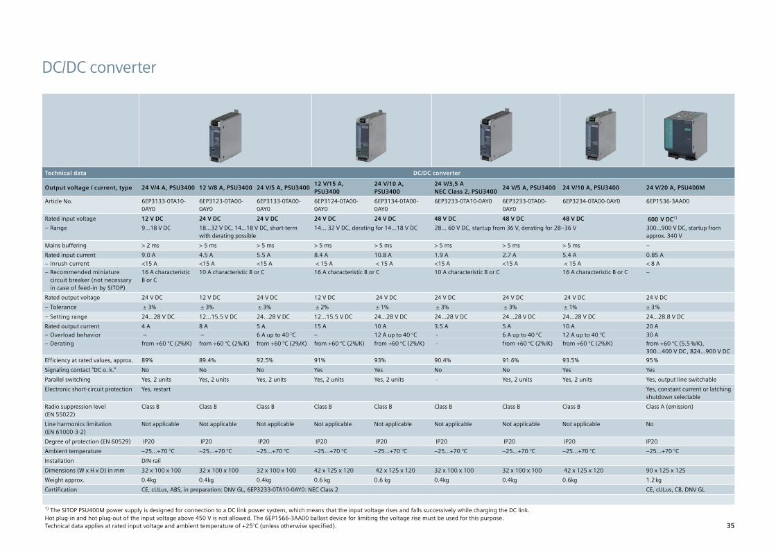
DC/DC converter
Technical data DC/DC converter
Output voltage / current, type 24 V/4 A, PSU3400 12 V/8 A, PSU3400 24 V/5 A, PSU3400 12 V/15 A, PSU3400
24 V/10 A, PSU3400
24 V/3,5 A NEC Class 2, PSU3400 24 V/5 A, PSU3400 24 V/10 A, PSU3400 24 V/20 A, PSU400M
Article No. 6EP3133-0TA10-0AY0
6EP3123-0TA00-0AY0
6EP3133-0TA00-0AY0
6EP3124-0TA00-0AY0
6EP3134-0TA00-0AY0
6EP3233-0TA10-0AY0 6EP3233-0TA00-0AY0
6EP3234-0TA00-0AY0 6EP1536-3AA00
Rated input voltage 12 V DC 24 V DC 24 V DC 24 V DC 24 V DC 48 V DC 48 V DC 48 V DC 600 V DC1)
– Range 9…18 V DC 18...32 V DC, 14...18 V DC, short-term with derating possible
14… 32 V DC, derating for 14…18 V DC 28… 60 V DC, startup from 36 V, derating for 28–36 V 300...900 V DC, startup from approx. 340 V
Mains buffering > 2 ms > 5 ms > 5 ms > 5 ms > 5 ms > 5 ms > 5 ms > 5 ms –Rated input current 9.0 A 4.5 A 5.5 A 8.4 A 10.8 A 1.9 A 2.7 A 5.4 A 0.85 A
– Inrush current <15 A <15 A <15 A < 15 A < 15 A <15 A <15 A < 15 A < 8 A – Recommended miniature circuit breaker (not necessary in case of feed-in by SITOP)
16 A characteristic B or C
10 A characteristic B or C 16 A characteristic B or C 10 A characteristic B or C 16 A characteristic B or C –
Rated output voltage 24 V DC 12 V DC 24 V DC 12 V DC 24 V DC 24 V DC 24 V DC 24 V DC 24 V DC – Tolerance ± 3% ± 3% ± 3% ± 2% ± 1% ± 3% ± 3% ± 1% ± 3 % – Setting range 24…28 V DC 12…15.5 V DC 24…28 V DC 12…15.5 V DC 24…28 V DC 24…28 V DC 24…28 V DC 24…28 V DC 24…28.8 V DC
Rated output current 4 A 8 A 5 A 15 A 10 A 3.5 A 5 A 10 A 20 A – Overload behavior – – 6 A up to 40 °C – 12 A up to 40 °C - 6 A up to 40 °C 12 A up to 40 °C 30 A – Derating from +60 °C (2%/K) from +60 °C (2%/K) from +60 °C (2%/K) from +60 °C (2%/K) from +60 °C (2%/K) - from +60 °C (2%/K) from +60 °C (2%/K) from +60 °C (5.5 %/K),
300...400 V DC , 824…900 V DC Efficiency at rated values, approx. 89% 89.4% 92.5% 91% 93% 90.4% 91.6% 93.5% 95 %Signaling contact “DC o. k.” No No No Yes Yes No No Yes YesParallel switching Yes, 2 units Yes, 2 units Yes, 2 units Yes, 2 units Yes, 2 units - Yes, 2 units Yes, 2 units Yes, output line switchableElectronic short-circuit protection Yes, restart Yes, constant current or latching
shutdown selectableRadio suppression level (EN 55022)
Class B Class B Class B Class B Class B Class B Class B Class B Class A (emission)
Line harmonics limitation (EN 61000-3-2)
Not applicable Not applicable Not applicable Not applicable Not applicable Not applicable Not applicable Not applicable No
Degree of protection (EN 60529) IP20 IP20 IP20 IP20 IP20 IP20 IP20 IP20 IP20Ambient temperature –25…+70 °C –25…+70 °C –25…+70 °C –25…+70 °C –25…+70 °C –25…+70 °C –25…+70 °C –25…+70 °C –25…+70 °CInstallation DIN railDimensions (W x H x D) in mm 32 x 100 x 100 32 x 100 x 100 32 x 100 x 100 42 x 125 x 120 42 x 125 x 120 32 x 100 x 100 32 x 100 x 100 42 x 125 x 120 90 x 125 x 125Weight approx. 0.4kg 0.4kg 0.4kg 0.6 kg 0.6 kg 0.4kg 0.4kg 0.6kg 1.2 kgCertification CE, cULus, ABS, in preparation: DNV GL, 6EP3233-0TA10-0AY0: NEC Class 2 CE, cULus, CB, DNV GL
1) The SITOP PSU400M power supply is designed for connection to a DC link power system, which means that the input voltage rises and falls successively while charging the DC link. Hot plug-in and hot plug-out of the input voltage above 450 V is not allowed. The 6EP1566-3AA00 ballast device for limiting the voltage rise must be used for this purpose. Technical data applies at rated input voltage and ambient temperature of +25°C (unless otherwise specified). 35

SITOP in special designs and applications
Technical data Wall mountingOutput voltage/current, type 12 V/3 A, PSU100D 24 V/2,1 A, PSU100D 24 V/3,1 A, PSU100D 24 V/4,1 A, PSU100D 12 V/8,3 A, PSU100D 24 V/6,2 A, PSU100D 24 V/12,5 A, PSU100DArticle No. 6EP1321-1LD00 6EP1331-1LD00 6EP1332-1LD00 6EP1332-1LD10 6EP1322-1LD00 6EP1333-1LD00 6EP1334-1LD00Rated input voltage 100–240 V AC 100–240 V AC 100–240 V AC 100–240 V AC 100–240 V AC 100–240 V AC 100–240 V AC
– Range 85...264 V AC 85...264 V AC 85...264 V AC 85...264 V AC 85...264 V AC 85...264 V AC 85...264 V ACMains buffering > 15 ms
(at 115/230 V)> 15 ms (at 115/230 V)
> 15 ms (at 115/230 V)
> 15 ms (at 115/230 V)
> 15 ms (at 115/230 V)
> 15 ms (at 115/230 V)
> 15 ms (at 115/230 V)
Rated line frequency 50/60 Hz 50/60 Hz 50/60 Hz 50/60 Hz 50/60 Hz 50/60 Hz 50/60 HzRated input current 0.75–0.5 A 1.1–0.7 A 1.5–1.0 A 2.0–1.1 A 2.0–1.1 A 3.1–2.0 A 4.0–2.0 A
– Inrush current1) < 60 A < 60 A < 60 A < 75 A < 75 A < 75 A < 60 A – Recommended miniature circuit breaker
10 A characteristic C, 16 A characteristic B
Rated output voltage 12 V DC 24 V DC 24 V DC 24 V DC 12 V DC 24 V DC 24 V DC – Tolerance ± 2 % ± 2 % ± 2 % ± 2 % ± 2 % ± 2 % ± 2 % – Setting range 11…14 V DC 22...28 V DC 22...28 V DC 22...28 V DC 11…14 V DC 22...28 V DC 22...28 V DC
Rated output current – Derating
3 A from +50 °C (2.5 %/K)
2.1 A from +50 °C (2.5 %/K)
3.1 A from +50 °C (2.5 %/K)
4.1 A from +50 °C (2.5 %/K)
8.3 A from +50 °C (2.5 %/K)
6.2 A from +50 °C (2.5 %/K)
12.5 A from +50 °C (2.5 %/K)
Efficiency at rated values, approx.
84 % 86 % 86 % 86 % 84 % 86 % 86 %
Signaling contact “DC o. k.” No No No No No No No
Remote On/Off No No No No No No NoParallel switching Yes Yes Yes Yes Yes Yes YesElectronic short-circuit protection Yes, restart Yes, restart Yes, restart Yes, restart Yes, restart Yes, restart Yes, restartRadio interference suppression (EN 55022)
Class B Class B Class B Class B Class B Class B Class B
Supply harmonics limitation (EN 61000-3-2)
Not applicable Not applicable Yes Yes Yes No Yes
Degree of protection (EN 60529)
IP20 IP20 IP20 IP20 IP20 IP20 IP20
Ambient temperature –10...+70 °C –10...+70 °C –10...+70 °C –10...+70 °C –10...+70 °C –10...+70 °C –10...+70 °CInstallation Wall mounting, variable installation positionDimensions (W x H x D) in mm 97 x 98 x 38 97 x 128 x 38 97 x 128 x 38 97 x 158 x 38 97 x 158 x 38 97 x 178 x 38 105 x 199 x 41Weight approx. 0.37 kg 0.35 kg 0.37 kg 0.50 kg 0.57 kg 0.55 kg 0.81 kgCertification
CE, cULu, cURus CE, cULus, cURus CE, cULus, cURus CE, cULus, cURus CE, cULus, cURus CE, cULus, cURus CE, cULus, cURus
1) Inrush current can be limited by a SITOP inrush current limiter: 6EP4683-6LB00-0AY0 (max. 5 A, 100–240 V AC). Technical data applies at rated input voltage and ambient temperature of +25°C (unless otherwise specified).
36

Two outputs Flexible output 0–52 V High degree of protection Slim design Flat design Slim design Power supplies for charging batteries2 x 15 V/3,5 A, SITOP PSU3600 3…52 V/10A, SITOP PSU3600 24 V/5 A, PSU100P 24 V/8 A, PSU100P1) 24 V/5 A, PSU300E 48 V/5 A, PSU100E 12 V/20 A, PSU3800 24 V/17 A, PSU3800 24 V/30 A, 40 A, PSU38006EP3323-0SA00-0BY0 6EP3343-0SA00-0AY0 6EP1333-7CA00 6EP1334-7CA00 6EP1433-0AA00 6EP3344-0SB00-0AY0 6EP3424-8UB00-0AY0 6EP3436-8UB00-0AY0 6EP3437-8UB00-0AY01)
120–230 V AC, 110-220 V DC 120–230 V AC, 110–220 V DC 120/230 V AC, automatic range switching 400 V 3 AC 120/230 V AC 400–500 V 3 AC 400–500 V 3 AC 400–500 V 3 AC85...264 V AC, 88...250 V DC 85...264 V AC, 88...250 V DC 85… 132/170… 264 V AC 320…480 V 3 AC 85...132/170...264 V AC 320…575 V 3 AC 320…575 V 3 AC 320…575 V 3 AC> 80 ms (at 230 V) > 80 ms (at 230 V) > 40 ms (at IOut rated) > 40 ms (at IOut rated) > 50 ms (at 400 V) > 20 ms (at 93/187 V) > 15 ms (at 400 V) > 15 ms (at 400 V) > 10 ms (at 400 V)
50/60 Hz 50/60 Hz 50/60 Hz 50/60 Hz 50/60 Hz 50/60 Hz 50/60 Hz 50/60 Hz 50/60 Hz2.2-1.3 A 2.6-1.3 A 2.25 A/1.24 A 3.5 A/1.52 A 0.36 A 4.4–2 A 0.7–0.6 A 1.2–1.0 A 2.1–1.7 A< 35 A < 35 A < 15 A < 15 A < 15 A < 58 A < 18 A < 18 A < 13 A6–10 A characteristic C 6–10 A characteristic C from 6 A charact. C/B from 6 A charact. C/B 6–10 A charact. C 10 A charact. C 6–16 A charact. C 3-ph. coupled or 3RV2011-1DA10
or 3RV2711-1DD1010 –16 A charact. C 3-ph. coupled or 3RV2011-1DA10 or 3RV2711-1DD10
2 x 15 V DC 24 V DC 24 V DC 24 V DC 24 V DC 48 V DC 12 V DC 24 V DC 24 V DC± 1% ± 1 % ± 3% ± 3% ± 3 % ± 3% ± 3 % ± 3 % ± 3 %12…28 V DC 0…52 V DC2) – – 24…29 V DC 48...54 V DC 12…14 V DC 24...28.8 V DC 24...28.8 V DC2 x 3.5 A (max. 60 W per output)–
2–10 A (max. 120 W) –
5 A –
8 A –
5 A–
5 Afrom +60 °C
20 A–
17 Afrom +60 °C (1.7%/K)
30 A/40 A switchablefrom +60 °C (5%/K)
88% 88 % 90 % 93 % 90 % 92 % 94 % 94 % 94 %
No Yes, and current monitor Yes Yes Yes Yes Yes Yes Yes
No No No No No No Yes Yes YesYes Yes Yes, two units Yes, two units No Yes, two units Yes Yes YesYes, restart Yes, constant current Yes, restart Yes, restart Yes, restart Yes, restart Yes, constant current or latching shutdown selectableClass B
Class B Class B Class B Class A Class A Class B Class B Class B
Yes Yes Yes Yes Yes Yes Yes Yes Yes
IP20
IP20 IP67, UL: enclosure type 4 indoor IP20 IP20 IP20 IP20 IP20
–25…+70 °C –25…+70 °C –25...+60 °C –25...+60 °C 0…+60 °C –25…+70 °C –25...+70 °C –25…+70 °C –25...+70 °CDIN rail DIN rail Screw mounting Screw mounting DIN rail DIN rail DIN rail DIN rail DIN rail42 x 125 x 125 42 x 125 x 135 120 x 181x 60,5 42 x 125 x 125 42 x 125 x 125 70 x 125 x 125 70 x 125 x 125 135 x 145 x 1500.55 kg 0.55 kg 1.1 kg 1.3 kg 0.6 kg 0.5 kg 1.2 kg 1.2 kg 3.3 kg CE, cULus, NEC Class 2 CE, cULus CE, cULus CE, cULus CE, cULus CE, cULus CE, cULus, ATEX, CCC, cCSAus Class I Div. 2, DNV GL, ABS CE; cULus, CB, ATEX, IECEx, CCC,
cCSAus Class I Div 2, SEMI F47,
1) Inrush current can be limited by a SITOP inrush current limiter: 6EP4683-6LB00-0AY0 (max. 5 A, 100–240 V AC) or 6EP1967-2AA00 (max. 10 A, 100–480 V AC, 1 unit per phase required). 2) Via analog voltage signal 0....2.5 VSpecifications at rated input voltage and ambient temperature +25 °C (unless otherwise specified)
37

SITOP expansion modules to increase system availability
Technical data RedundancySITOP SITOP RED1200 redundancy module SITOP PSE202U redundancy moduleArticle No. 6EP4346-7RB00-0AX0 6EP4347-7RB00-0AX0 6EP1964-2BA00 6EP1962-2BA00 6EP1961-3BA21Rated input voltage
– Range12 V, 24 V, 48 V DC10…58 V DC
12 V, 24 V, 48 V DC10…58 V DC
24 V DC 19…29 V DC
24 V DC 19…29 V DC
24 V DC 24…28.8 V DC
Brief description of product/function Module for redundancy mode and for decoupling power supplies with output voltages from 12 to 48 V, e.g. for series connection to increase voltage to up to 96 V or parallel connection of more than 2 power supplies to enhance performance.
Module for redundancy mode; floating relay contact and green LED for signaling “Infeed 1 and 2 o.k.”, switching threshold adjustable between 20 and 25 V DC
Possible combinations Decoupling of two 12 V to 48 V power supplies with output currents up to 10 A or one 20-A power supply per redundancy module
Decoupling of two 12 V to 48 V power supplies with output currents up to 20 A or one 40-A power supply per redundancy module
Decoupling of two 24-V power supplies up to 5 A or one 10-A power supply per redundancy module
Decoupling and limitation of the output to Class-2 limit (100 VA) of two 24-V power supplies 5 to 40 A
Decoupling of two 24-V power supplies 5 A to 20 A or one 40-A power supply per redundancy module
Rated output current 20 A (total output current) 40 A (total output current) 10 A (total output current) 3.5 A1) 40 A (total output current)Reverse voltage protection 200 V DC 200 V DC 52 V DC 52 V DC 52 V DC Efficiency at rated values, approx. 97.5 % 97.5 % 97 % 95 % 97 %Radio interference suppression (EN 55022)
Class B Class B Class B Class B Class B
Degree of protection (EN 60529) IP20 IP20 IP20 IP20 IP20Terminals Push-in Push-in Screw terminals Screw terminals Screw terminalsAmbient temperature –30…+70 °C –30…+70 °C –20…+70 °C –20…+70 °C –25…+60 °C Dimensions (W x H x D) in mm 35 x 135 x 125 45 x 135 x 125 30 x 80 x 100 30 x 80 x 100 70 x 125 x 125Weight approx. 0.35 kg 0.35 kg 0.125 kg 0.125 kg 0.5 kgCertification CE, cULus, CB, ATEX, IECex, CCC, in preparation: cCSAus Class1 div2,
DNV GL, ABS CE, cULus CE, cULus, NEC Class 2 CE, cULus, cCSAus Class I Div 2,
ATEX, IECEx, CCC, DNV GL, ABS
1) Max. 8 A summation current in fault case in accordance with NEC Class 2 Specifications at rated input voltage and ambient temperature +25 °C (unless otherwise specified)
38

Technical data MonitoringSITOP SITOP SEL1200 selectivity module with switching
characteristicSITOP SEL1400 selectivity module with current limiting characteristic
SITOP PSE200U selectivity module with current limiting characteristic and common signaling contact
SITOP PSE200U selectivity module with current limiting characteristic and single-channel signaling
Article No. 6EP4437-7FB00-3CX0
6EP4437-7FB00-3DX0
6EP4438-7FB00-3DX0
6EP4437-7EB00-3CX0
6EP4437-7EB00-3DX0
6EP4438-7EB00-3DX0
6EP1961-2BA11 6EP1961-2BA21 6EP1961-2BA31 6EP1961-2BA41
Article No. with NEC Class 2 6EP1961-2BA51 6EP1961-2BA61Rated input voltage/range 24 V DC/20.4…30 V DC 24 V DC/20.4…30 V DC 24 V DC/22…30 V DC 24 V DC/22…30 V DC Brief product description Module for distributing the 24-V supply over up to four or eight load circuits and their monitoring for overload; selective shutdown of faulty load circuits, rated current individually adjustable; universal use
for all power suppliesSwitch-off characteristic Switching – for standard protection. Release time depending
on overcurrentCurrent limiting – for increased safeguarding requirements; current limitation to 150 % (110 % for NEC Class 2 variants) of the set threshold value, then shutdown. Voltage dip below 20 V not possible, therefore also suitable for loads that do not meet the PLC standard
Status indication per output 3-color LED: green – connected, yellow – manually disconnected, red – disconnected due to overcurrentSignal outputs Diagnostics interface for common signaling or single-channel diagnostics. Analysis of single-channel diagnostics via SIMATIC S7
function block: current, set current threshold value, status (on/off), reason for disconnection (if applicable)Common signaling contact. Voltage measuring points for current value per output (1 V ≙ 1 A)
Single-channel signaling for channel-specific analysis via SIMATIC S7-function block. Voltage measuring points for current value per output (1 V ≙ 1 A)
Reset, outputs switched on/off Remote reset with 24-V signal. Reset and each output switched on/off via push buttonIndividual load circuits switched on sequentially
Load-optimized (previous output less than set rated value) + 25 ms, + 200 ms, or + 500 ms 0 ms (simultaneously), 25 ms,100 ms or load-optimized (previous output less that set rated value)
Rated output current 4 x 10 A 8 x 5 A 8 x 10 A 4 x 10 A 8 x 5 A 8 x 10 A 4 x 3 A 4 x 10 A 4 x 3 A 4 x 10 A – Setting range 2…10 A 1…5 A 2…10 A 2…10 A 1…5 A 2…10 A 0,5…3 A 3…10 A 0,5…3 A 3…10 A
Efficiency at rated values, approx. typ. 98% typ. 98% typ. 98% typ. 98% typ. 98% typ. 98% 97 % 99 % 97 % 99 %Parallel switching of 2 outputs Yes (max. 15 A) Yes (max. 7.5 A) Yes (max. 15 A) Yes (max. 15 A) Yes (max. 7.5 A) Yes (max. 15 A) No No No NoElectronic short-circuit protection Yes Yes Yes Yes Yes Yes Yes Yes Yes YesRadio interference suppression (EN 55022)
Class B Class B Class B Class B Class B Class B Class B Class B Class B Class B
Degree of protection (EN 60529) IP20 IP20 IP20 IP20 IP20 IP20 IP20 IP20 IP20 IP20Terminals Push-in Push-in Push-in Push-in Push-in Push-in Screw terminals Screw terminals Screw terminals Screw terminalsAmbient temperature –25…+70 °C –25…+70 °C –25…+70 °C –25…+70 °C –25…+70 °C –25…+70 °C –25…+60 °C –25…+60 °C –25…+60 °C –25…+60 °CDimensions (W x H x D) in mm 45 x 135 x 125 45 x 135 x 125 45 x 135 x 125 45 x 135 x 125 45 x 135 x 125 45 x 135 x 125 72 x 80 x 72 72 x 80 x 72 72 x 80 x 72 72 x 80 x 72 Weight approx. 0.3 kg 0.3 kg 0.3 kg 0.3 kg 0.3 kg 0.3 kg 0.2 kg 0.2 kg 0.2 kg 0.2 kgCertification CE, UL, cULus, CB, CSA, ATEX, IECEx, CCC, in preparation: cCSAus Class I Div 2, GL und ABS CE, UL, cURus, CB, cULus Class I Div 2, ATEX, IECEx, CCC, DNV GL, ABS, 6EP1961-
BA51/6EP1961-2BA61: NEC Class 2
Technical data applies at rated input voltage and ambient temperature of +25°C (unless otherwise specified)
new! new! new! new!
39

Uninterruptible power supplies – SITOP UPS500 maintenance-free DC UPS with capacitor technology
Technical data Mains buffering up to the seconds range Mains buffering up to the minutes range
SITOP Buffer module1) SITOP PSE201U Buffer module SITOP BUF1200 UPS500S–basic unit 15 A UPS501S – expansion module
Buffer time/Energy 200 ms/40 A 300 ms/40 A 2.5 kWs 5 kWs 5 kWs
Article No. 6EP1961-3BA01 6EP4231-7HB00-0AX0 6EP1933-2EC41 6EP1933-2EC51 6EP1935-5PG01
Input voltage 24 V DC/24…28.8 V DC 24 V DC/20…30 V DC 24 V DC, 22…29 V, infeed from SITOP 24 V Infeed from basic unit
Rated input current Module for buffering during short power failures; parallel connection at output of 24-V power supplies1). Buffering time 200 ms at 40 A up to 1.6 s at 5 A load current; multiplication possible through parallel connection; maximum buffering time 10 s
Module for buffering during short power failures; parallel connection at output of 24-V power supplies. Buffering time 300 ms at 40 A up to 2.4 s at 5 A load current; multiplication possible through parallel connection
15.2 A + approx. 2.3 A in charging mode Description: expansion module for extending the buffering time, up to three units can be switched in parallel with one UPS500S basic unit
Rated output voltage In buffer and normal mode 24 V DC ± 3 %
Rated output current 15 A, charging current 1 A (factory setting) or 2 A selectable
Efficiency at rated values, approx. 97.5 %
Overload and short-circuit protection Electronic, automatic restart
Parallel switching Yes Yes No Yes, up to three units
Radio interference suppression (EN 55022)
Class B Class B Class B Class B Class B
Degree of protection (EN 60529) IP20 IP20 IP20 IP20 IP20
Ambient temperature 0…+60 °C –30 …+70 °C 0…+60 °C 0…+60 °C 0…+60 °C
Dimensions (W x H x D) in mm 70 x 125 x 125 70 x 135 x 155 120 x 125 x 125 120 x 125 x 125 70 x 125 x 125
Weight approx. 1.2 kg 1.5 kg 1.0 kg 1.0 kg 0.7 kg
Certification CE, UL, CSA, ATEX, CCC, UL Class I Div 2, DNV GL, ABS
CE, cULus, CB, SEMI F47, ATEX, CCC, in preparation: cCSAus Class I Div 2, DNV GL, ABS
CE, cULus, CB, ATEX, CCC, cCSAus Class I Div 2, DNV GL, ABS
1) Can be combined with SITOP PSU8200, PSU6200 and SITOP smart 24-V power supplies (except 6EP1 336-2BA10) Specifications at rated input voltage and ambient temperature +25 °C (unless otherwise specified)
SITOP expansion modules to increase system availability
40
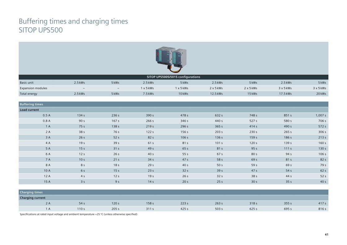
Buffering times and charging times SITOP UPS500
SITOP UPS500S/501S configurations
Basic unit 2.5 kWs 5 kWs 2.5 kWs 5 kWs 2.5 kWs 5 kWs 2.5 kWs 5 kWs
Expansion modules – – 1 x 5 kWs 1 x 5 kWs 2 x 5 kWs 2 x 5 kWs 3 x 5 kWs 3 x 5 kWs
Total energy 2.5 kWs 5 kWs 7.5 kWs 10 kWs 12.5 kWs 15 kWs 17.5 kWs 20 kWs
Buffering times
Load current
0.5 A 134 s 236 s 390 s 478 s 632 s 748 s 851 s 1,007 s
0.8 A 90 s 167 s 266 s 346 s 440 s 527 s 580 s 706 s
1 A 75 s 138 s 219 s 296 s 365 s 414 s 490 s 572 s
2 A 38 s 76 s 122 s 156 s 203 s 230 s 265 s 306 s
3 A 26 s 52 s 82 s 106 s 136 s 159 s 186 s 213 s
4 A 19 s 39 s 61 s 81 s 101 s 120 s 139 s 160 s
5 A 15 s 31 s 49 s 65 s 81 s 95 s 111 s 130 s
6 A 12 s 26 s 40 s 55 s 67 s 80 s 94 s 106 s
7 A 10 s 21 s 34 s 47 s 58 s 69 s 81 s 82 s
8 A 8 s 18 s 29 s 40 s 50 s 59 s 69 s 79 s
10 A 6 s 15 s 23 s 32 s 39 s 47 s 54 s 62 s
12 A 4 s 12 s 19 s 26 s 32 s 38 s 44 s 52 s
15 A 3 s 9 s 14 s 20 s 25 s 30 s 35 s 40 s
Charging times
Charging current
2 A 54 s 120 s 158 s 223 s 263 s 318 s 355 s 417 s
1 A 110 s 205 s 311 s 425 s 503 s 625 s 695 s 816 sSpecifications at rated input voltage and ambient temperature +25 °C (unless otherwise specified)
41

Technical data Mains buffering up to the hours range Mains buffering up to the hours rangeSITOP UPS1600 UPS1600 UPS1600 Battery module UPS1100 Battery module UPS1100 UPS1100 battery module UPS1100 battery module UPS1100 battery module with
extended temperature rangeUPS1100 battery module, lithium technology
Energy storage Lead storage batteries Lead storage batteries Lead batteries Lead batteries Pure-lead batteries LiFePO batteriesOutput voltage/current or charge 24 V/10 A 24 V/20 A 24 V/40 A 24 V/1.2 Ah 24 V/3.2 Ah 24 V/7 Ah 24 V/12 Ah 24 V/2.5 Ah 24 V/5 Ah
for UPS1600 10 A for UPS1600 10 A and 20 A for UPS1600 10 A, 20 A, and 40 A
for UPS1600 10 A, 20 A and 40 A
for UPS1600 10 A and 20 A for UPS1600 10 A and 20 A
Article No. 6EP4134-3AB00-0AY0 6EP4136-3AB00-0AY0 6EP4137-3AB00-0AY0 6EP4131-0GB00-0AY0 6EP4133-0GB00-0AY0 6EP4134-0GB00-0AY0 6EP4135-0GB00-0AY0 6EP4132-0GB00-0AY0 6EP4133-0JB00-0AY0– with USB interface 6EP4134-3AB00-1AY0 6EP4136-3AB00-1AY0 6EP4137-3AB00-1AY0– with Ethernet/PROFINET interface 6EP4134-3AB00-2AY0 6EP4136-3AB00-2AY0 6EP4137-3AB00-2AY0Input voltage 24 V DC, 22...29 V, infeed from 24-V SITOP power supply Recommended end-of-charge voltage
(set automatically by SITOP UPS1600)Recommend end-of-charge voltage: set automatically by SITOP UPS1600
Rated input current approx. 14 A at max. charging current (3 A)
approx. 25 A at max. charging (4 A)
approx. 46 A at max. charging (5 A) Charging current max. 0.3 A Charging current max. 0.9 A Charging current max. 2.1 A
Charging current max. 3.6 A
Charging current max. 0.7 A Charging current max. 2.1 A
Rated output voltage 24 V DC (upstream SITOP device or battery), charging voltage: 27.0 V 24 V DC, 22...27.0 V DC (no-load operation) 24 V DC, 22...27.0 V DC (no-load operation) 24 V DC, 22...28.8 V DC (no-load operation)
Rated output current 10 A, charging current 20 A, charging current 40 A, charging current max. 5 A 10 A 20 A 40 A 40 A 20 A 20 A– Overload behavior (power boost for 30 ms) 30 A 60 A 120 A– Overload behavior (extra power for 5 s/min) 15 A 30 A 60 AEfficiency at rated values, approx. > 97.7 % > 98.2 % > 98.8 % Not applicable Not applicable Not applicable Not applicable Not applicable Not applicableOverload and shortcircuit protection Yes, restart in normal mode Installed battery fuse: 15 A/32 V Installed battery fuse: 25 A/32 V Installed battery fuse: 2 x
25 A/32 VInstalled battery fuse: 2 x 25 A/32 V
Installed battery fuse: 25 A/32 V
Installed battery fuse: 25 A/32 V
Parallel switching No No No Yes, up to six units Yes, up to six units Yes, up to six units Yes, up to six units Yes, up to six units Yes, up to six unitsRadio interference suppression Class B (EN 55022) Class B (EN 55022) Class B (EN 55022) – – – – – –Degree of protection (EN 60529) IP20 IP20 IP20 IP20 IP20 IP20 IP20 IP20 IP20Ambient temperature (derating from +60 °C) –25...+70 °C –25...+70 °C –25...+70 °C –15...+50 °C –15...+50 °C –15...+50 °C –15...+50 °C –40…+60 °C –20…+50 °CInstallation DIN rail DIN rail DIN rail DIN rail or wall mounting DIN rail or wall mounting Wall mounting Wall mounting DIN rail or wall mounting DIN rail or wall mountingDimensions (W x H x D) in mm 50 x 125 x 125 50 x 125 x 125 70 x 125 x 150 89 x 130 x 107 190 x 169 x 79 186 x 186 x 110 253 x 186 x 110 265 x 115 x 76 189 x 186 x 113Weight approx. 0.38/0.4/0.44 kg 0.39/0.41/0.45 kg 0.65/0.65/0.7 kg 1.9 kg 3.8 kg 6.1 kg 9.3 kg 3.7 kg 3.4 kgCertification CE, cULus, CB, ATEX, IECEx, CCC, cCSAus Class I Div 2,
DNV GL, ABSCE, cULus, CB, ATEX, IECEx, CCC, cCSAus Class I Div 2, DNV GL, ABS
CE, cURus, CB, ATEX, IECEx, CCC, cCSAus Class I Div 2, DNV GL, ABS
CE, cURus, CB, ATEX, IECEx, CCC, cCSAus Class I Div 2, DNV GL, ABS
CE, cURus, CB, ATEX, IECEx, CCC, cCSAus Class I Div 2, DNV GL, ABS
CE, cURus, CB, ATEX, IECEx, CCC, cCSAus Class I Div 2, DNV GL, ABS
CE, cURus, CB, ATEX, IECEx, CCC, cCSAus Class I Div 2, DNV GL, ABS
CE, cURus, CB, DNV GL, ABS
Specifications at rated input voltage and ambient temperature +25 °C (unless otherwise specified) 1) Buffer time determination is based on the discharging time of new and completely charged battery modules with a minimum battery temperature of +25 °C until DC UPS (19 V) turns off. The SITOP Selection Tool can be used to determine buffer times for additional temperatures and buffer voltages: siemens.com/tst-powersupply 2) With two parallel connected UPS1100 battery modules and UPS1600 40 A
Uninterruptible power supplies SITOP DC UPS with battery modules for bridging longer power failures
42

Technical data Mains buffering up to the hours range Mains buffering up to the hours rangeSITOP UPS1600 UPS1600 UPS1600 Battery module UPS1100 Battery module UPS1100 UPS1100 battery module UPS1100 battery module UPS1100 battery module with
extended temperature rangeUPS1100 battery module, lithium technology
Energy storage Lead storage batteries Lead storage batteries Lead batteries Lead batteries Pure-lead batteries LiFePO batteriesOutput voltage/current or charge 24 V/10 A 24 V/20 A 24 V/40 A 24 V/1.2 Ah 24 V/3.2 Ah 24 V/7 Ah 24 V/12 Ah 24 V/2.5 Ah 24 V/5 Ah
for UPS1600 10 A for UPS1600 10 A and 20 A for UPS1600 10 A, 20 A, and 40 A
for UPS1600 10 A, 20 A and 40 A
for UPS1600 10 A and 20 A for UPS1600 10 A and 20 A
Article No. 6EP4134-3AB00-0AY0 6EP4136-3AB00-0AY0 6EP4137-3AB00-0AY0 6EP4131-0GB00-0AY0 6EP4133-0GB00-0AY0 6EP4134-0GB00-0AY0 6EP4135-0GB00-0AY0 6EP4132-0GB00-0AY0 6EP4133-0JB00-0AY0– with USB interface 6EP4134-3AB00-1AY0 6EP4136-3AB00-1AY0 6EP4137-3AB00-1AY0– with Ethernet/PROFINET interface 6EP4134-3AB00-2AY0 6EP4136-3AB00-2AY0 6EP4137-3AB00-2AY0Input voltage 24 V DC, 22...29 V, infeed from 24-V SITOP power supply Recommended end-of-charge voltage
(set automatically by SITOP UPS1600)Recommend end-of-charge voltage: set automatically by SITOP UPS1600
Rated input current approx. 14 A at max. charging current (3 A)
approx. 25 A at max. charging (4 A)
approx. 46 A at max. charging (5 A) Charging current max. 0.3 A Charging current max. 0.9 A Charging current max. 2.1 A
Charging current max. 3.6 A
Charging current max. 0.7 A Charging current max. 2.1 A
Rated output voltage 24 V DC (upstream SITOP device or battery), charging voltage: 27.0 V 24 V DC, 22...27.0 V DC (no-load operation) 24 V DC, 22...27.0 V DC (no-load operation) 24 V DC, 22...28.8 V DC (no-load operation)
Rated output current 10 A, charging current 20 A, charging current 40 A, charging current max. 5 A 10 A 20 A 40 A 40 A 20 A 20 A– Overload behavior (power boost for 30 ms) 30 A 60 A 120 A– Overload behavior (extra power for 5 s/min) 15 A 30 A 60 AEfficiency at rated values, approx. > 97.7 % > 98.2 % > 98.8 % Not applicable Not applicable Not applicable Not applicable Not applicable Not applicableOverload and shortcircuit protection Yes, restart in normal mode Installed battery fuse: 15 A/32 V Installed battery fuse: 25 A/32 V Installed battery fuse: 2 x
25 A/32 VInstalled battery fuse: 2 x 25 A/32 V
Installed battery fuse: 25 A/32 V
Installed battery fuse: 25 A/32 V
Parallel switching No No No Yes, up to six units Yes, up to six units Yes, up to six units Yes, up to six units Yes, up to six units Yes, up to six unitsRadio interference suppression Class B (EN 55022) Class B (EN 55022) Class B (EN 55022) – – – – – –Degree of protection (EN 60529) IP20 IP20 IP20 IP20 IP20 IP20 IP20 IP20 IP20Ambient temperature (derating from +60 °C) –25...+70 °C –25...+70 °C –25...+70 °C –15...+50 °C –15...+50 °C –15...+50 °C –15...+50 °C –40…+60 °C –20…+50 °CInstallation DIN rail DIN rail DIN rail DIN rail or wall mounting DIN rail or wall mounting Wall mounting Wall mounting DIN rail or wall mounting DIN rail or wall mountingDimensions (W x H x D) in mm 50 x 125 x 125 50 x 125 x 125 70 x 125 x 150 89 x 130 x 107 190 x 169 x 79 186 x 186 x 110 253 x 186 x 110 265 x 115 x 76 189 x 186 x 113Weight approx. 0.38/0.4/0.44 kg 0.39/0.41/0.45 kg 0.65/0.65/0.7 kg 1.9 kg 3.8 kg 6.1 kg 9.3 kg 3.7 kg 3.4 kgCertification CE, cULus, CB, ATEX, IECEx, CCC, cCSAus Class I Div 2,
DNV GL, ABSCE, cULus, CB, ATEX, IECEx, CCC, cCSAus Class I Div 2, DNV GL, ABS
CE, cURus, CB, ATEX, IECEx, CCC, cCSAus Class I Div 2, DNV GL, ABS
CE, cURus, CB, ATEX, IECEx, CCC, cCSAus Class I Div 2, DNV GL, ABS
CE, cURus, CB, ATEX, IECEx, CCC, cCSAus Class I Div 2, DNV GL, ABS
CE, cURus, CB, ATEX, IECEx, CCC, cCSAus Class I Div 2, DNV GL, ABS
CE, cURus, CB, ATEX, IECEx, CCC, cCSAus Class I Div 2, DNV GL, ABS
CE, cURus, CB, DNV GL, ABS
Specifications at rated input voltage and ambient temperature +25 °C (unless otherwise specified) 1) Buffer time determination is based on the discharging time of new and completely charged battery modules with a minimum battery temperature of +25 °C until DC UPS (19 V) turns off. The SITOP Selection Tool can be used to determine buffer times for additional temperatures and buffer voltages: siemens.com/tst-powersupply 2) With two parallel connected UPS1100 battery modules and UPS1600 40 A
Battery module selection table: buffer times and service life
UPS1100 battery module
1.2 Ah 3.2 Ah 7 Ah 12 Ah 2.5 Ah 5 Ah
Load current Buffering times 1)
1 A 27 min 2 h 5 h 8 h 30 min
1 h 30 min
4 h
2 A 14 min 1 h 2 h 40 min
4 h 30 min
50 min 2 h 10 min
3 A 10 min 45 min 1 h 50 min
3 h 10 min
36 min 1 h 30 min
4 A 7 min 50 s
34 min 1 h 20 min
2 h 30 min
26 min 1 h 10 min
6 A 4 min 40 s
21 min 48 min 1 h 30 min
15 min 48 min
8 A 3 min 15 min 34 min 1 h 11 min 37 min
10 A 1 min 30 s
9 min 30 s
21 min 42 min 6 min 40 s
26 min
12 A – 8 min 10 s
19 min 37 min 5 min 40 s
23 min
14 A – 6 min 50 s
16 min 32 min 4 min 40 s
21 min
16 A – 5 min 30 s
13 min 27 min 3 min 40 s
18 min
20 A – 2 min 50 s
7 min 50 s
17 min 1 min 40 s
13 min
30 A – – 3 min 50 s
10 min 3 min 20 s, 2x2)
17 min, 2x2)
40 A – – 1 min 40 s
5 min 30 s
1 min 40 s, 2x2)
13 min, 2x2)
Ambient temperature
Approximate service life (drop to 80% of the original capacity), depending on battery temperature
+20 °C 4 years 4 years 4 years 4 years 10 years 15 years
+30 °C 2 years 2 years 2 years 2 years 7 years 10 years
+40 °C 1 year 1 year 1 year 1 year 3 years 9 years
+50 °C 0.5 years 0.5 years 0.5 years 0.5 years 1.5 years 2 years
+60 °C 1 year
43

Find out more:siemens.com/sitop
More about SITOP on YouTube
Additional information on SITOP:
TIA Selection Tool: siemens.com/tst-powersupply
Operating instructions as download: siemens.com/sitop/manuals
Request CAx data via the CAx download manager: siemens.com/cax
Published by Siemens AG
Digital Industries Process Automation Östliche Rheinbrückenstr. 50 76187 Karlsruhe, Germany
For the U.S. published by Siemens Industry Inc 100 Technology Drive Alpharetta, GA 30005 United States
Follow us on: twitter.com/siemensindustry youtube.com/siemens
Subject to changes and errors. The information provided in this brochure contains descriptions or performance characteristics which, in case of actual use, do not always apply as described or which may change as a result of further development of the products. The desired performance characteristics are only binding if expressly agreed in the contract. Availability and technical specifications are subject to change without notice.
All product designations may be trademarks or product names of Siemens AG or supplier companies, the use of which by third parties for their own purposes may violate the rights of the owners.
Industrial Security Siemens provides automation and drive products with industrial-security functions that support the secure operation of plants or machines. They are an important component in a holistic industrial-security concept. With this in mind, our products undergo continuous development. We therefore recommend that you keep yourself informed with respect to our product updates and that you use only the latest versions. Please find further information on this subject at automation.siemens.com/support. You may also register for a product-specific newsletter at this address.
To ensure the secure operation of a plant or machine it is also necessary to take suitable preventive action (e.g., cell protection concept) and to integrate the automa- tion and drive components into a state-of-the-art holistic industrial-security concept for the entire plant or machine. Any third-party products that may be in use must also be taken into account. Please find further information at siemens.com/industrialsecurity.
Article No.: DIPA-B10072-02-7600 Dispo 10001 WS 01211.5 Printed in Germany © Siemens 2021


