
Site Soil Evaluation Design Report - Kingborough Council
26
1 Site & soil evaluation and design report. Proposed on-site wastewater management system at 23 Stuart Street, Alonnah, TAS 7150 Richard Mason, Onsite Assessments Tas 20 Adelong Drive, Kingston [email protected] Mobile 0418 589309
Transcript of Site Soil Evaluation Design Report - Kingborough Council
1
Site & soil evaluation and design report. Proposed on-site wastewater management system at 23 Stuart Street, Alonnah, TAS 7150
Richard Mason, Onsite Assessments Tas
20 Adelong Drive, Kingston
Mobile 0418 589309

2
SITE AND SOIL EVALUATION REPORT
BACKGROUND This report and design information has been provided in order to assist the client in considering options an onsite wastewater management system to service a new house at 23 Stuart Street, Alonnah. The information provided in this Report provides Design Information, Plans and Specifications suitable for inclusion in supporting documentation to enable the client to apply for a Plumbing Permit for an on-site wastewater management system.
SITE INFORMATION Location: 23 Stuart Street, Alonnah, TAS 7150. PID: 3481049 TITLE REF: 168800/8 Client/owner: Andrew Boyd Project Summary: The developer proposes to construct a new 2-bedroom house. Soil profile and site characteristics limit the prospects for installing an in-ground land application area on the site. It is therefore proposed to install an aerobic wastewater treatment system discharging disinfected secondary treated wastewater to a subsurface irrigation system. The natural soil profile in the proposed land application area is gradational, with clay loam (depth 100mm) overlying Category 6 medium clay to 1400mm+. Site area: 0.2579Ha. Soil profile 1. A Horizon: 0-100mm: silty clay loam, greyish brown 5Y 3/2, moderate structure; fine roots,
damp, Category 4. 2. B Horizon: 100 – 1400mm+; medium clay, moderate brown 5YR 4/4, damp to moist with depth,
massive; Category 6. Measured or Estimated Soil Permeability (m/d) Estimated from textural classification.
A Horizon 0.12-0.5m/day B Horizon <0.06m/day Effluent Application Rates (This is a recommendation to the designer advising how many litres of effluent should be applied to the soil for every square metre of absorption trench or other land application system.) AWTS & irrigation 2⁰ treated effluent – 2mm/day (1mm/day – slope factor adjustment.)
3
Absorption trench/bed - not suitable Soil profile characteristics (Cat 6) preclude use of in-ground trenches or beds. Topography The slope within the land application area is 15° / 25%, towards the SSE. Drainage lines / water courses: Minor drainage line runs a minimum of 15m downslope-slope from the proposed land application area. Vegetation: The land application area has been previously cleared of native forest vegetation and is now dominated by low/recent regrowth of along with sparse grass, blackberries, thistles and flat weeds. Geology: Shown on LISTmap geological layer as Jurassic dolerite, which is consistent with site observations. Site History (land use) Site subdivided for medium density residential use in 2016; there are no known prior uses of the site which would compromise the installation and sustainable operation of an onsite wastewater management system. Site Exposure and Climate. Aspect: The proposed land application area site has a southerly aspect. Pre-dominant wind direction: North-west to south-westerly. Climate: Annual rainfall averages 947mm/year (Great Bay), retained rain (RR) of 805mm/year with maximum daily average temperature of 18.3ºC and minimum of 11.3ºC (Cape Bruny)), giving an annual evapotranspiration (ET) of 613mm. Annual average RR on this site is predicted to exceed average annual ET by 192mm. Environmental Issues Location of sensitive vegetation, high water table, swamps, waterways etc. The vegetation on this site has been highly altered by the previous subdivision works, with all mature native vegetation having been removed from the proposed land application area; the operation of an on-site wastewater management system on this site would not result in harm to natural flora values. There are no water bores depicted on the MRT Groundwater Information Portal within 200m of this site. A minor drainage line runs through the centre of the lot; location and design of the land application area with respect to the drainage line is consistent with Code E23 Part 10.1 Clause P2. Drainage/Groundwater Depth to seasonal groundwater (m) Shallow groundwater was not detected in test borings to 1400mm depth, however soils are damp to moist with increasing depth.
4
Site Stability The site is not shown as being affected by a Landslide layer under the Interim Planning Scheme or MRT Landslide Hazard Band. Wastewater application by shallow subsurface irrigation at low DIR is considered to present a low risk for slope stability. On Site Wastewater Management System Options. Given the soil profile constraints of the site and proximity to creekline, secondary treatment of wastewater is required prior to land disposal/absorption by subsurface irrigation; an accredited aerobic wastewater treatment system meets this requirement. Land Application Area The land application area is to comprise a subsurface irrigation system, which will be located 15m to the north of the drainage line running through the centre of the lot. Water Supply Rainwater tank.
Loadings. Accommodation will comprise a 2-bedroom house, with assumed maximum occupancy of four persons; per capita wastewater loading is assumed to be 120 litres per day, giving a total loading of 480 litres per day. This assumes rainwater tank supply as per AS/NZS1547.2012, Table H1. Design Irrigation Rate A DIR of 2mm per day appropriate for the Category 6 soil profile is selected; as the slope lies in the 20-30% range, a 50% slope reduction factor is applicable; DIR is therefore reduced to 1mm/day. Wastewater Land Application Area. Subsurface irrigation area required:
= daily wastewater loading / Design irrigation rate = 480 litres per day / 1mm day = 480m2
The covered surface irrigation system dripper line is fitted with pressure compensated drippers which trigger at 1.4m static head, therefore the unregulated fall across the irrigation field should not exceed this figure. Slope measurement in the land application area indicates a likely maximum fall across the land application area of approximately 4.75m; subdivision of the irrigation system into zones not exceeding 1.3m vertical fall, by installation of zone/non-return valves is therefore required.

5
Irrigation area hydraulic design summary
Length dripperline (m)
Dripper spacing
Dripper flow rate (l/hr)
Number of drippers
Total dripper flow rate L/hr
Total dripper flow rate (L/min) Head loss (m)
480 0.3 2.3 1600 3680 61.33333333
Length supply pipe
Material supply pipe ID pipe
Friction loss (m) at flow rate
L/min
44 LDPE 32 3.1 3.1
Friction loss from other pipe fittings
25% 0.78 0.78
Type of filter Make Model Friction loss
(m) at flow rate L/min
disc Netafim 1.5” (35mm) 0.733 0.733
Type of indexing valve Model
Friction loss (m) at flow rate
L/min
K Rain RCW4402 0
Total Friction head (m) 4.61
Differential elevation (pump to
irrigation area) in (m)
3 Elevation head (m) 3
Operating head of
dripperline (m) Operating head (m)
10 10 10
Total Dynamic Head (TDH) in m 17.61
Required pump capacity (minimum) @ 62 L/min 17.61 TDH
Pump selection
AWTS unit Pump as supplied Minimum required operating head at 62L/min
Operating head at 62L/min (from published pump curve data)
Pump suitable for flow/head
requirement? Fujiclean
CE1500EX Claytech Blue Diver 30 18m 20m Yes
Taylex ABS
Davey D42 18m 26m Yes
Envirocycle 10ANR
Zenox ZHS-040 18m 16m No
Graf EPro 15 Three O+
Zenox ZHS-040 18m 16m No
Zenox ZHS-075 18m 20m Yes

6
Standard pumps as supplied with the Fujiclean and Taylex units will supply the irrigation area zones at the required pressure and flow rate. The Envirocycle and Graf units will require fitting with a Zenox ZHS-075 or similar; (supplies 62L/min @ 20m head.)
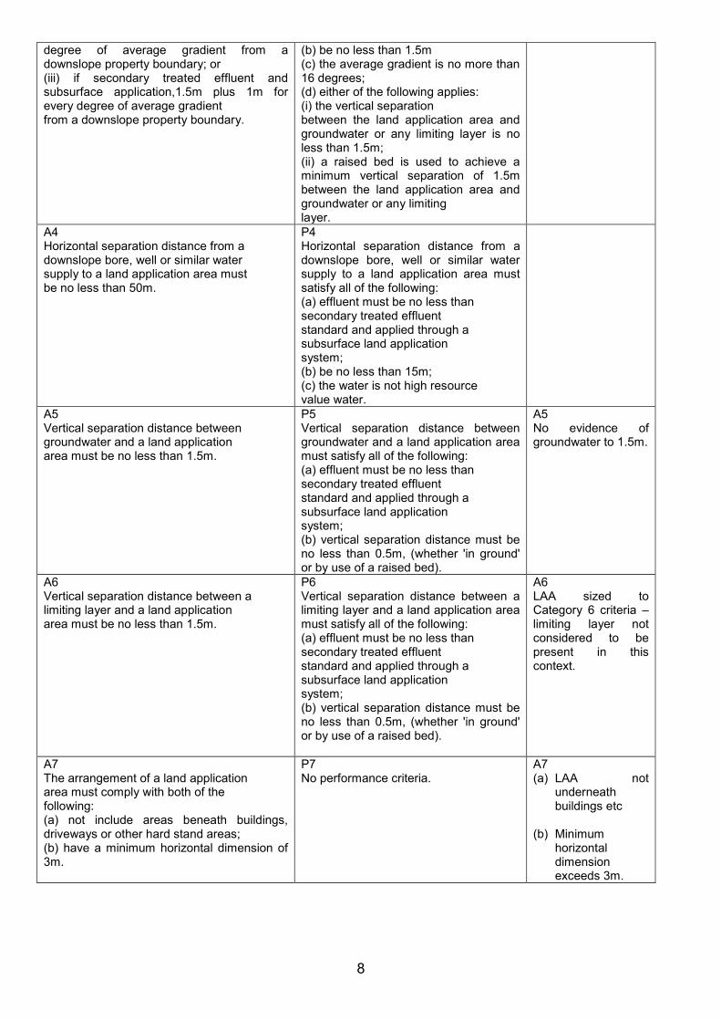
Compliance Table Code E23 Acceptable Solutions Performance Criteria Compliance
achieved by E.23.7.1 Development Standards for Residential Development
A1 A new dwelling must be provided with a land application area that complies with Table E23.1.
P1 The land application area is of sufficient size to comply with the requirements of AS/NZ1547.
P1 Land application area size meets AS/NZS1547.2012.
A2 An addition or alteration to an existing dwelling, or change of use to a dwelling, must not encroach onto an existing land application area and comply with at least one of the following: (a) not increase the number of bedrooms or otherwise increase the potential volume of wastewater generated onsite; (b) not increase the number of bedrooms or otherwise increase the potential volume of wastewater generated onsite to greater than that allowed for in the design of the existing OWMS; (c) provide a land application area that complies with Table E23.1.
P2 The land application area is of sufficient size to comply with the requirements of AS/NZ1547.
n/a
E.23.8.1 Development Standards for Non-Residential Development
A1 A land application area for non-residential development must comply with the following: (a) if including bedrooms, (such as visitor accommodation), the size of the land application areas must comply with Table E.23.1; (b) if other development, design flow rates must be no less than the rates provided in the following table: Wastewater Fixture: Flow Design Allowance per person per day: Closet Pan: 50L Urinals 25L Washbasin: 10L Shower: 30L Bath: 30L Laundry: 30L
P1 The land application area is of sufficient size to comply with the requirements of AS/NZ1547.
n/a
E.23.9.1 Development Standards for New Lots
A1 A new lot must have an area no less than:
P1 The area of a new lot must be adequate to accommodate a land application area of sufficient size to
n/a
7
5,000 m2. comply with the requirements of AS/NZ1547 for a dwelling containing a minimum of 3 bedrooms.
E.23.9.2 Development Standards for New Boundaries
A1 A new boundary must have a separation distance from an existing land application area that complies with E.23.10.1 A3.
P1 A new boundary must have a separation distance from an existing land application area that satisfies E.23.10.1 P3.
n/a
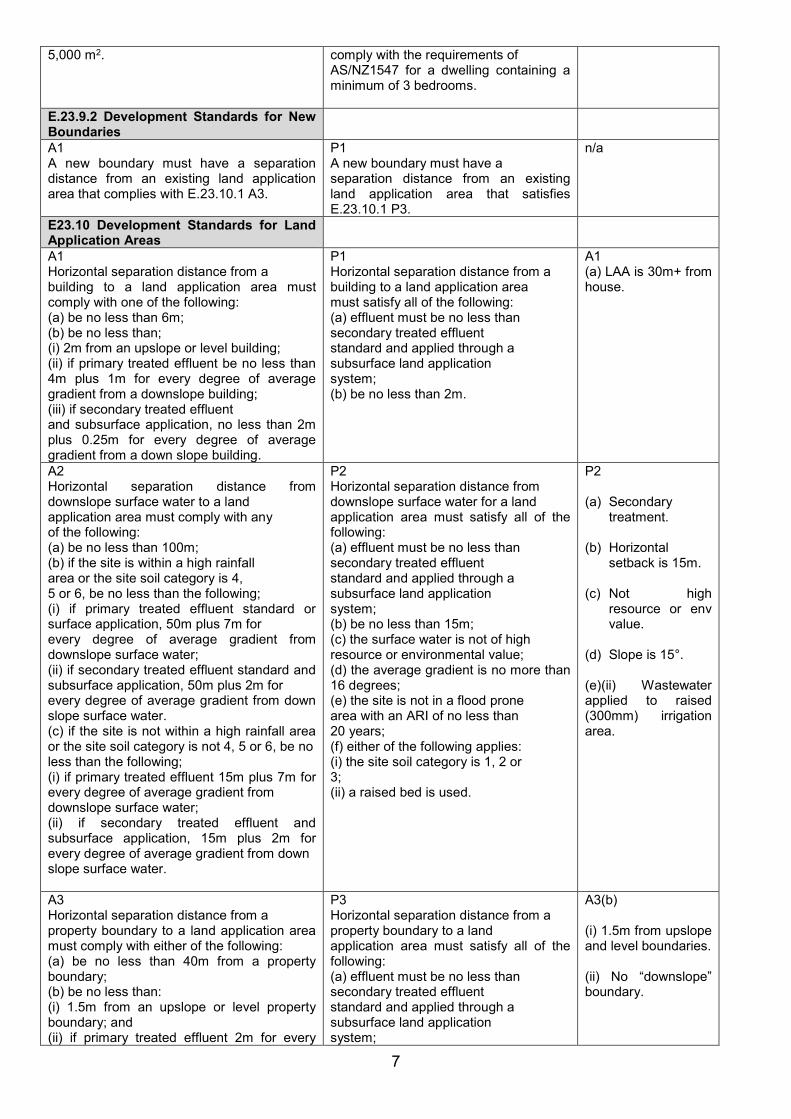
E23.10 Development Standards for Land Application Areas
A1 Horizontal separation distance from a building to a land application area must comply with one of the following: (a) be no less than 6m; (b) be no less than; (i) 2m from an upslope or level building; (ii) if primary treated effluent be no less than 4m plus 1m for every degree of average gradient from a downslope building; (iii) if secondary treated effluent and subsurface application, no less than 2m plus 0.25m for every degree of average gradient from a down slope building.
P1 Horizontal separation distance from a building to a land application area must satisfy all of the following: (a) effluent must be no less than secondary treated effluent standard and applied through a subsurface land application system; (b) be no less than 2m.
A1 (a) LAA is 30m+ from house.
A2 Horizontal separation distance from downslope surface water to a land application area must comply with any of the following: (a) be no less than 100m; (b) if the site is within a high rainfall area or the site soil category is 4, 5 or 6, be no less than the following; (i) if primary treated effluent standard or surface application, 50m plus 7m for every degree of average gradient from downslope surface water; (ii) if secondary treated effluent standard and subsurface application, 50m plus 2m for every degree of average gradient from down slope surface water. (c) if the site is not within a high rainfall area or the site soil category is not 4, 5 or 6, be no less than the following; (i) if primary treated effluent 15m plus 7m for every degree of average gradient from downslope surface water; (ii) if secondary treated effluent and subsurface application, 15m plus 2m for every degree of average gradient from down slope surface water.
P2 Horizontal separation distance from downslope surface water for a land application area must satisfy all of the following: (a) effluent must be no less than secondary treated effluent standard and applied through a subsurface land application system; (b) be no less than 15m; (c) the surface water is not of high resource or environmental value; (d) the average gradient is no more than 16 degrees; (e) the site is not in a flood prone area with an ARI of no less than 20 years; (f) either of the following applies: (i) the site soil category is 1, 2 or 3; (ii) a raised bed is used.
P2 (a) Secondary
treatment.
(b) Horizontal setback is 15m.
(c) Not high
resource or env value.
(d) Slope is 15°.
(e)(ii) Wastewater applied to raised (300mm) irrigation area.
A3 Horizontal separation distance from a property boundary to a land application area must comply with either of the following: (a) be no less than 40m from a property boundary; (b) be no less than: (i) 1.5m from an upslope or level property boundary; and (ii) if primary treated effluent 2m for every
P3 Horizontal separation distance from a property boundary to a land application area must satisfy all of the following: (a) effluent must be no less than secondary treated effluent standard and applied through a subsurface land application system;
A3(b) (i) 1.5m from upslope and level boundaries. (ii) No “downslope” boundary.
8
degree of average gradient from a downslope property boundary; or (iii) if secondary treated effluent and subsurface application,1.5m plus 1m for every degree of average gradient from a downslope property boundary.
(b) be no less than 1.5m (c) the average gradient is no more than 16 degrees; (d) either of the following applies: (i) the vertical separation between the land application area and groundwater or any limiting layer is no less than 1.5m; (ii) a raised bed is used to achieve a minimum vertical separation of 1.5m between the land application area and groundwater or any limiting layer.
A4 Horizontal separation distance from a downslope bore, well or similar water supply to a land application area must be no less than 50m.
P4 Horizontal separation distance from a downslope bore, well or similar water supply to a land application area must satisfy all of the following: (a) effluent must be no less than secondary treated effluent standard and applied through a subsurface land application system; (b) be no less than 15m; (c) the water is not high resource value water.
A5 Vertical separation distance between groundwater and a land application area must be no less than 1.5m.
P5 Vertical separation distance between groundwater and a land application area must satisfy all of the following: (a) effluent must be no less than secondary treated effluent standard and applied through a subsurface land application system; (b) vertical separation distance must be no less than 0.5m, (whether 'in ground' or by use of a raised bed).
A5 No evidence of groundwater to 1.5m.
A6 Vertical separation distance between a limiting layer and a land application area must be no less than 1.5m.
P6 Vertical separation distance between a limiting layer and a land application area must satisfy all of the following: (a) effluent must be no less than secondary treated effluent standard and applied through a subsurface land application system; (b) vertical separation distance must be no less than 0.5m, (whether 'in ground' or by use of a raised bed).
A6 LAA sized to Category 6 criteria – limiting layer not considered to be present in this context.
A7 The arrangement of a land application area must comply with both of the following: (a) not include areas beneath buildings, driveways or other hard stand areas; (b) have a minimum horizontal dimension of 3m.
P7 No performance criteria.
A7 (a) LAA not
underneath buildings etc
(b) Minimum horizontal dimension exceeds 3m.

9
On Site Wastewater Management System Summary. The client proposes to install either a Taylex ABS, a Fujiclean CE1500EX, an Envirocycle 10ANR or a Graf Claro EPro15 aerobic wastewater treatment system unit, all of which are accredited as approved systems by the Director of Building; Certificate of Accreditation. Date of Site Visit: 07.01.2019 Weather conditions: Warm and fine on day of visit, with 62mm of rain (Alonnah School) falling since 01/12/2018. Further Information. For further detailed assessment and design information, together with operation and maintenance advice, please refer to the Appendices.
10
Statement. I certify that this Site and Soil Evaluation and Design for an on-site wastewater management system for the proposed residential development at 23 Stuart Street, Alonnah has been undertaken in accordance with the relevant provisions of AS/NZS 1547:2012. Onsite Domestic Wastewater Management, with respect to the design of on-site wastewater management systems requiring a Plumbing Permit. The design of this on-site wastewater system is suitable for the proposed residence referred to in this report. This report is copyrighted to me as the author. I authorise Andrew Boyd, Kingborough Council and their respective agents and/or employees to make copies or extracts of this report for the purposes of Planning and/or Building Applications etc for the above-mentioned project on this site by or on behalf of Michelle Woodgate. Please Note: It is generally understood that the successful operation of an on-site wastewater disposal system is dependent upon a number of complex, interacting factors and that the operating life of in-ground absorption systems in particular may be limited. This system may require future maintenance or modification to ensure its continued satisfactory operation. The client is advised that such works are the responsibility of the property owner. SITE ASSESSOR AND SYSTEM DESIGNER NAME: Richard Mason, Environmental Health Professional & Accredited Building Services Hydraulic Designer. NAME OF ORGANISATION: Onsite Assessment Tas. ADDRESS: 20 Adelong Drive, Kingston, Tasmania, 7050 CONTACT DETAILS: 0418 589 309; [email protected]
SIGNED: DATED: 19.02.2019
11
APPENDICES 1 - Site Location 12 2 – Site Photos 13 3 – Soil testing 14 4 – Design plans 15 5 – Design specifications 20 6 – Advice to project manager and installer 22 7 - Loading Certificate and O & M requirements 23 8 – Form 35 27
12
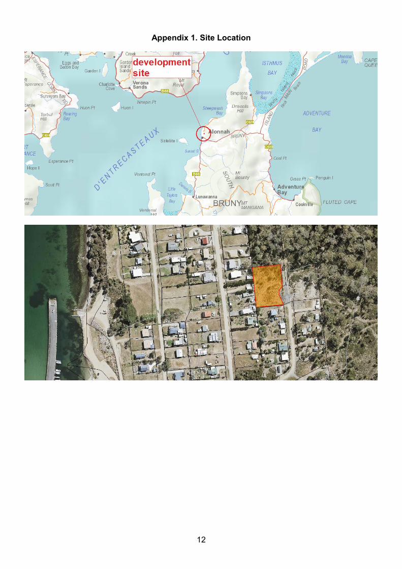
Appendix 1. Site Location
13
Appendix 2 - Site photos
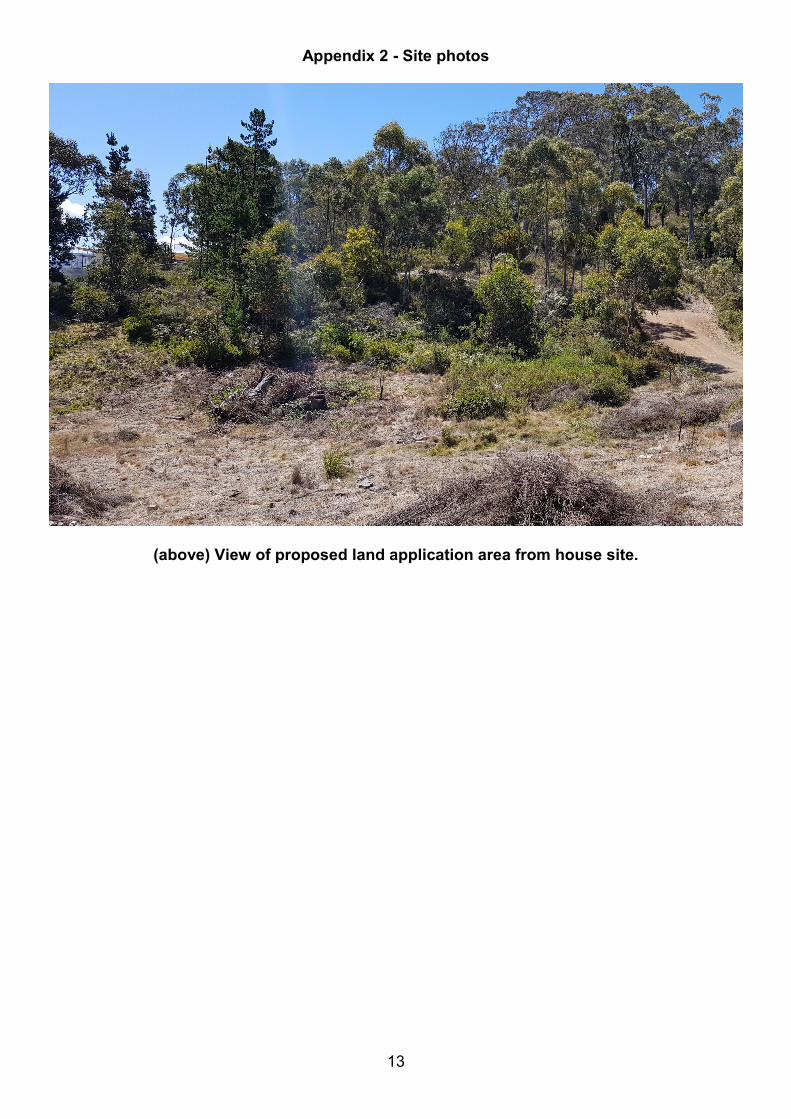
(above) View of proposed land application area from house site.
14
Appendix 3 – Soil testing
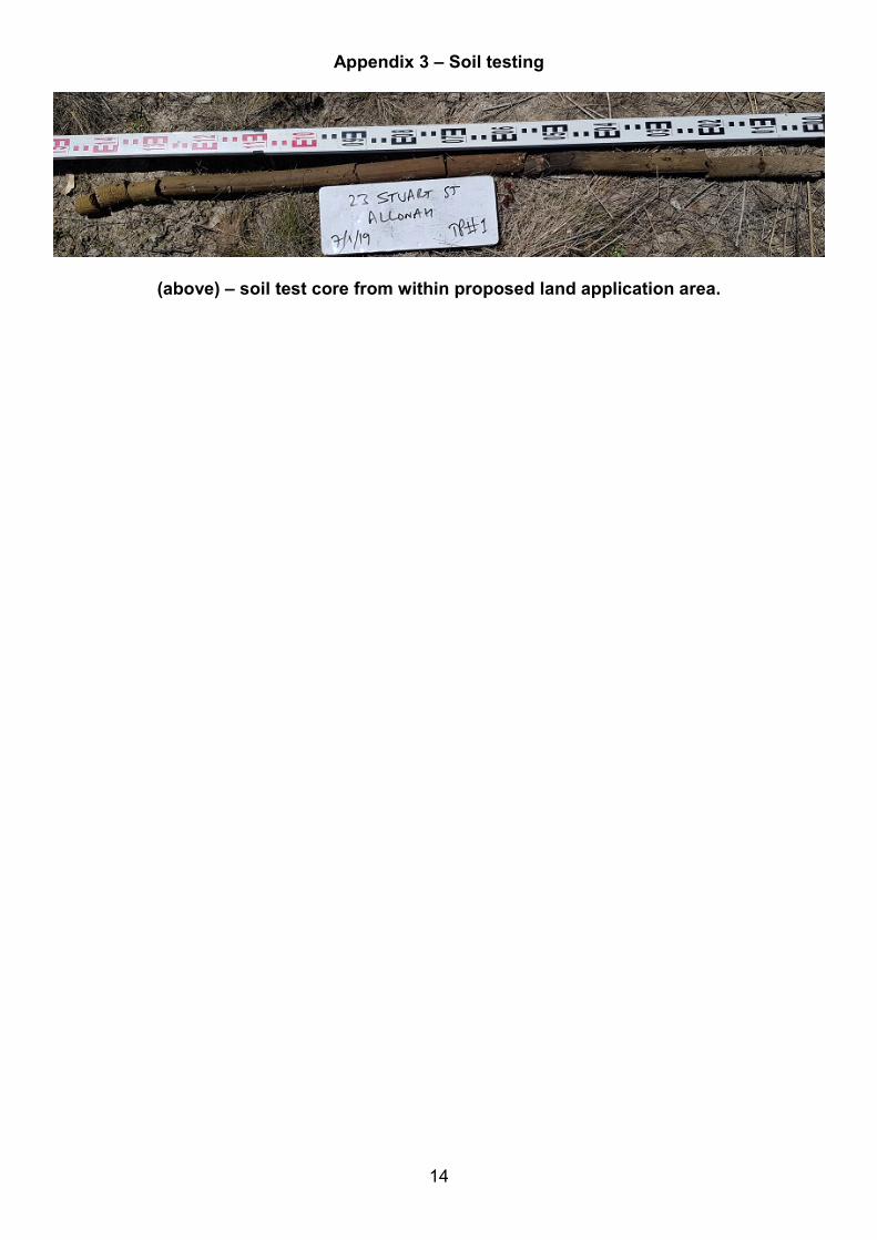
(above) – soil test core from within proposed land application area.
15
Appendix 4 - Design plans.
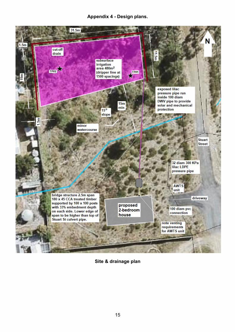
Site & drainage plan
16
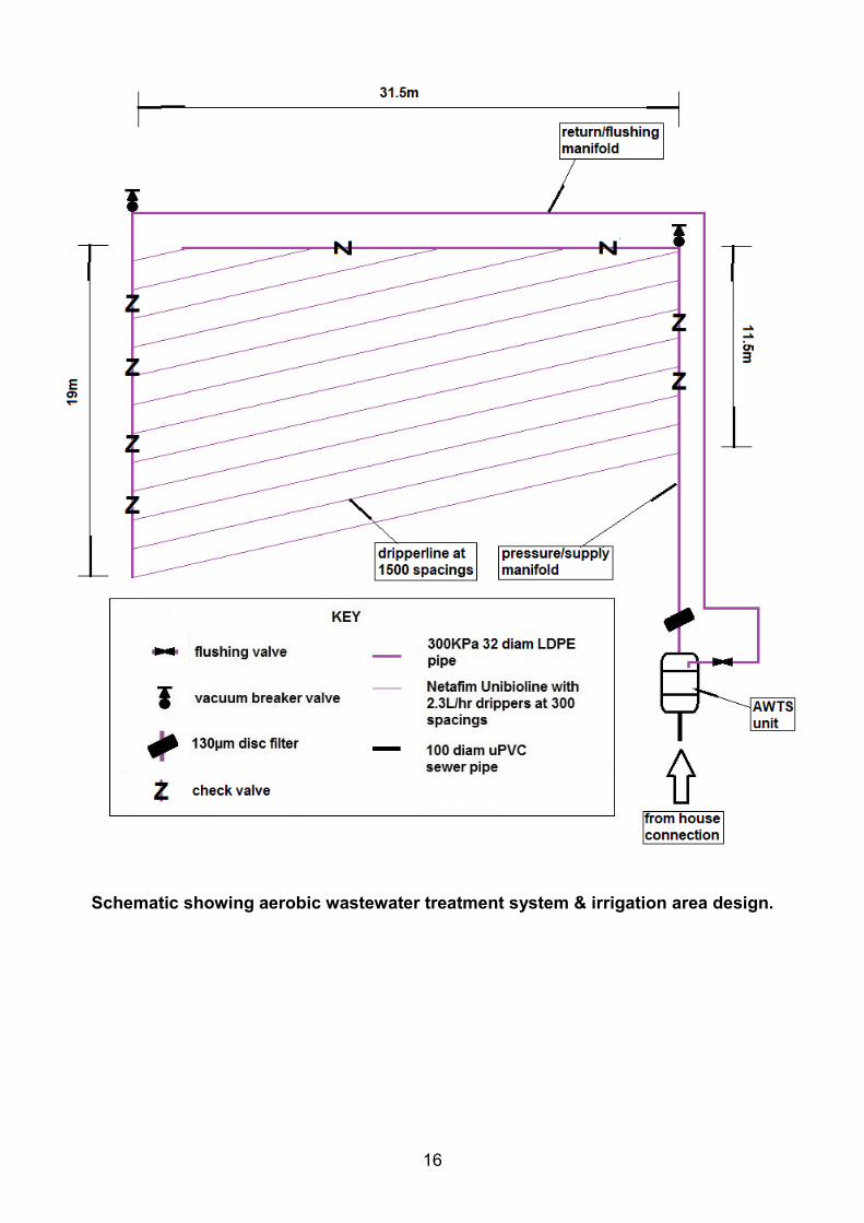
Schematic showing aerobic wastewater treatment system & irrigation area design.
17
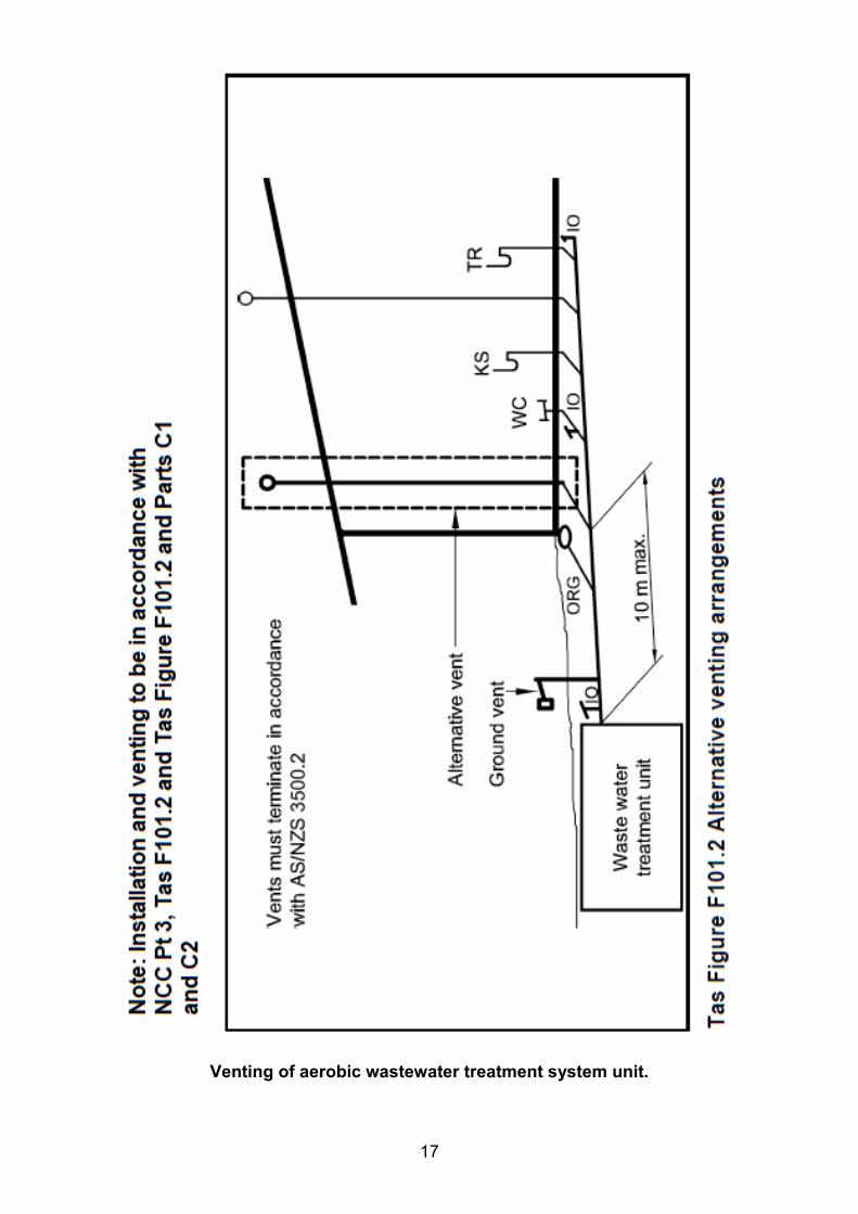
Venting of aerobic wastewater treatment system unit.
18
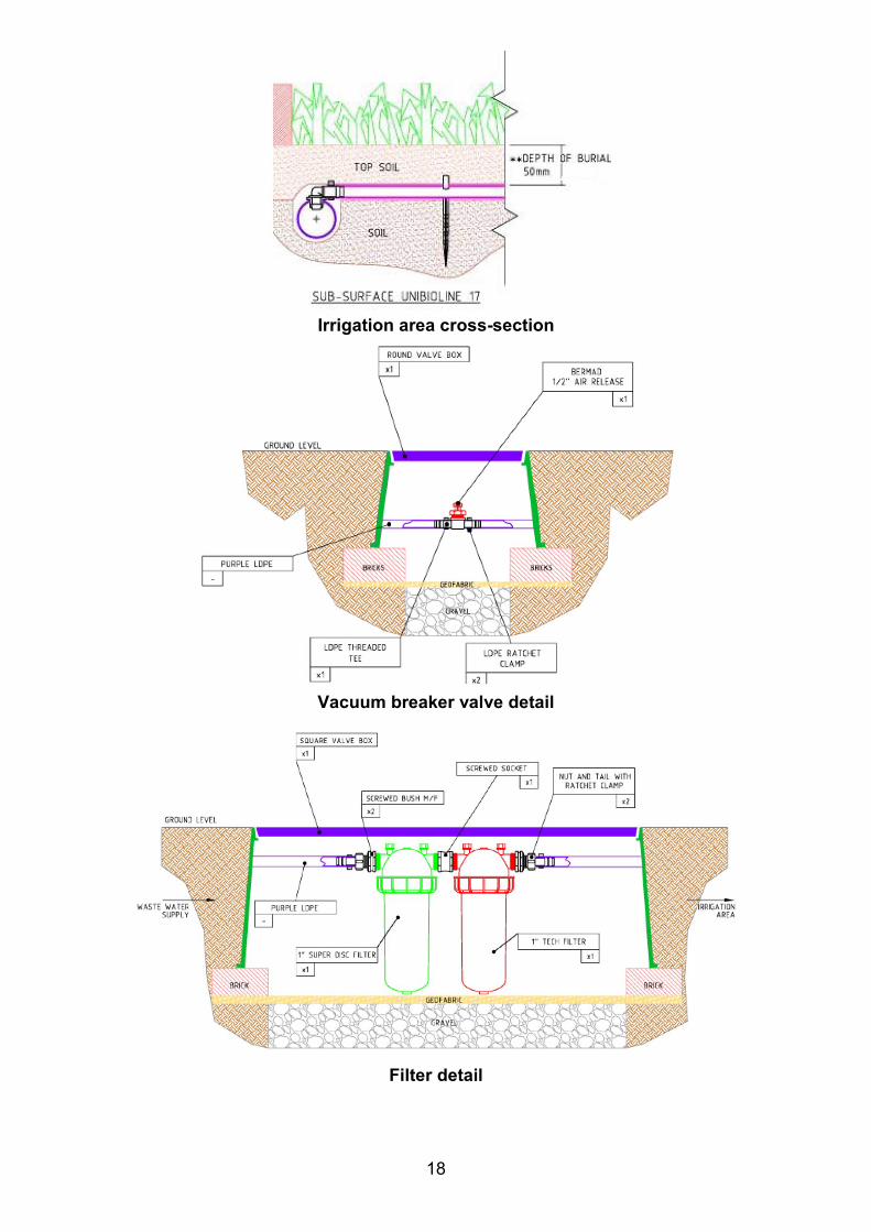
Irrigation area cross-section
Vacuum breaker valve detail
Filter detail
19
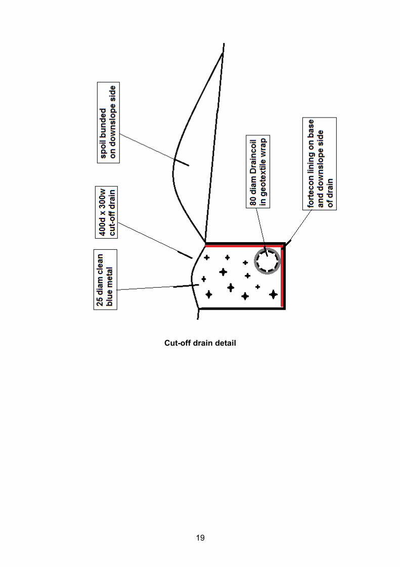
Cut-off drain detail
20
Appendix 5 – Design specifications.
1. Recommended aerobic wastewater treatment system units for this application are as follows:
2. Taylex ABS - Certificate of Accreditation – FOL/16/5463 Graf EPro 15 Three O+ Certificate of Accreditation – DOC/16/69061
Fuji Clean CE1500EX - Certificate of Accreditation – DOC/16/84418
Envirocycle 10ANR - Certificate of Accreditation – DOC/17/44413
3. AWTS unit installation and venting to be in accordance with NCC Pt 3, Tas F101.2 and Tas Figure F101.2 and Parts C1 and C2.
4. Supply manifold from aerobic wastewater treatment system to be fitted with a 130µm
disc filter.
5. Drip irrigation system is “UniBioline” by Netafim or Toro; 16-17mm OD polypipe with inbuilt 2.0- 2.3L/hr drip emitters, (or similar), at 1000mm spacings.
6. Irrigation area to be ripped/scarified to a depth of 150mm and treated with gypsum at a
rate of 0.5kg/m2, prior to placement of irrigation infrastructure.
7. Lay dripper line at 1500mm centres between Supply and Return manifolds, each comprising 32mm diameter 300KPa lilac LD polyethylene pipe, as per irrigation area details in Appendix 4.
8. Spread imported sand and sandy loam to a depth of 150mm over the nominated
irrigation area, with 1500mm wide batter to original ground surface
9. Vacuum breakers cut into highest point on the Return Manifold as per attached plan in Appendix 4.
10. Install non-return/check valves in supply and return manifolds at 1.3m vertical intervals. 11. All valves and breakers to be placed in valve boxes with lilac screw-down covers flush to
finished ground surface.
12. Supply manifold connected to lowest points on irrigation area, return manifold runs from highest points on irrigation area.
13. Manual or automatic flushing valve to be provided in return line, discharging back to
secondary settlement chamber of Aerated Wastewater Treatment unit. 14. Drainage from upslope areas etc to be directed away from irrigation area by means of
upslope cut-off drain constructed as per details in Appendix 4. Drain to be configured and orientated to discharge surface water flows clear of the irrigation area.
15. AWTS unit and irrigation area to be commissioned and reported in accordance with
Clauses M11, M12, M13 & M14 of AS/NZS1547.2012
21
16. Condition and performance of wastewater land application area to be monitored and reported during routine quarterly maintenance inspections.
17. L7 CONSTRUCTION TECHNIQUES (AS/NZS1547.2012 On-site domestic
wastewater management.) L7.1 Good construction technique The following excavation techniques shall be observed so as to minimise the risk of damage to the soil: (a) Plan to excavate only when the weather is fine;
(b) Avoid excavation when the soil has a moisture content above the plastic limit. This can
be tested by seeing if the soil forms a ‘wire’ when rolled between the palms; (c) During wet seasons or when construction cannot be delayed until the weather becomes fine, smeared soil surfaces may be raked to reinstate a more natural soil surface, taking care to use fine tines and only at the surface; (d) When excavating by machine, fit the bucket with ‘raker teeth’ if possible, and excavate in small ‘bites’ to minimise compaction; and (e) Avoid compaction by keeping people off the finished trench or bed floor. In particular for trenches and beds: (f) If rain is forecast then cover any open trenches, to protect them from rain damage; (g) Excavate perpendicular to the line of fall or parallel to the contour of sloping ground; and (h) Ensure that the inverts are excavated level.
CL7.1 Damage can be done by: (a) Smearing, where the soil surface is smoothed, filling cracks and pores;
(b) Compacting, where the soil porosity is reduced; and
(c) Puddling, where washed clay settles on the base of the trench to form a relatively impermeable layer. In particular, cohesive soils, or soils containing a significant quantity of clay, are susceptible to damage by excavation equipment during construction.
22
Appendix 6 – Advice to Project manager.
Important notes for Project Manager. It is vitally important to the future of the on-site wastewater management system to avoid damage to soil structure on the site, which would reduce soil permeability, leading to possible early failure of the effluent absorption trenches. Actions that may damage soil structure include: • Compaction, which reduces soil porosity; • Smearing, where soil surfaces are smoothed, filling pores and cracks; and, The Effluent Irrigation Area must be carefully constructed to ensure its optimal operation. Project Manager Responsibilities. The Project Manager must ensure that: 1. Before project construction work commences, the Effluent Absorption Area is properly
identified on site and barricaded, fenced, roped or taped to prevent unauthorised access. This action should be documented both on the site plan and with the local Council.
2. Vehicles, earth-moving plant etc do not park or manoeuvre on the Effluent Absorption Area. 3. The Effluent Absorption Area is not used for the stockpiling of construction materials,
excavated fill or other materials. 4. All water runoff resulting from the construction of driveways, cut & fill and other excavations
is directed to discharge well away from and downslope of the Effluent Absorption Area.
23
Appendix 7 – Loading Certificate and Operation & Maintenance Requirements
A copy of the relevant aerobic wastewater treatment system Certificate of Accreditation and Owners' Manual is to be provided by the supplier; the home owner is advised to print two hard copies of the Accreditation publication, one of which should be submitted to the Council in support of the Special Plumbing Permit Application, and one copy of the Owners' Manual. Both should be retained and read for familiarisation purposes and the recommendations therein carefully followed in order to ensure optimal, nuisance free operation of the system with minimal environmental health impacts. This loading certificate is provided in accordance with Clause 7.4.2(d) of AS/NZS 1547.2012. Loading Certificate for proposed aerobic wastewater treatment system with covered surface wastewater irrigation at 23 Stuart Street, Alonnah.
i. System capacity (medium-long term) – 4 persons / 480 litres/day.
ii. Design criteria summary: • Effluent quality – secondary with disinfection • Soil category - 6 (1mm/day DIR) • Land application system - Subsurface irrigation (see Appendix M of AS/NZS1547.2012)
iii. Reserve area.
Sufficient land is available on site for secondary land application area if required.
iv. Water efficient fittings etc Design assumes use of water efficient fixtures and fittings, eg 3L/4.5L flush toilets, 9L/min (max) showerheads, aerator fittings on taps and clothes washing machines/dishwashers with WELSS star ratings of 4.5 stars or above. (see http://www.waterrating.gov.au/ )
v. Variation from design flows etc. The system should successfully manage additional peak loadings which may result from occasional social gatherings provided that this does not exceed use by more 15 persons in an 8-hour period or a total of 2 visitors temporarily resident (i.e. total of 6 persons) for a period not exceeding 14 days. Visitors should be advised of the requirement to minimise time spent in showers; avoid running taps whilst cleaning teeth and other common-sense water conservation measures.
vi. Consequences of changing wastewater characteristics. The home owner should avoid disposing of wastes which would be additional to those normally disposed in a household sewerage system; in particular increases, in organic loadings such as from the use of sink-waste disposal units are to be avoided. Use of household disinfectants or bactericides in anything more than small amounts and at recommended rates of dilution should also be avoided, as should the disposal of solvents and other chemicals or pharmaceuticals such as antibiotics or antimicrobials which may kill bacteria and other microorganisms required for effective wastewater treatment.
vii. Consequences of overloading the system. Long term use by more than 4 residents or equivalent may result in hydraulic overloading of the irrigation system, surfacing of effluent, public and environmental health nuisances, pollution of surface waters etc. Overloading may also result from such uses as residential childcare, home-catering and other wastewater-intensive home-based businesses etc.
viii. Consequences of underloading the system.
24
The system will work effectively with as few as one person in residence, however long periods of zero-occupancy may result in poor functioning of the system when normal use recommences. If you plan to leave the building unoccupied for more than one month, please advise the maintenance contractor. Similarly, if occupancy levels are suddenly changed such as if family or friends move in with you, or if usage changes markedly such as when changing from full time occupancy to part time usage, the maintenance contractor should also be advised.
ix. Consequences of lack of operation, maintenance and monitoring attention.
The AWTS requires regular 3-monthly maintenance by an authorised, trained technician, undertaken in accordance with a written maintenance contract. (Or at intervals specified in the aerobic wastewater treatment system unit’s Certificate of Accreditation.) Consequences of failure to observe the regular maintenance requirements may include any of the following:
• Spread of infectious diseases to your family and neighbours. • Nuisance and unpleasant odours. • Pollution of waterways, streams, beaches and shellfish beds. • Contamination of bores, wells and groundwater. • Excessive and unsightly weed growth. • Alteration of local ecology
• Operation & Maintenance Requirements
• Make sure that you have the septic tank desludged by an authorised contractor at three
yearly intervals. Failure to do this at the required frequency may result in carry-over of solids into the aerobic wastewater treatment and irrigation systems, causing failure of the land application area, which may then require expensive reconstruction works.
• Discourage access by visitors or pets to the land application area. • Livestock should not be allowed on or near the irrigation area; if such animals are kept, the
land application area should be fenced off to prevent system damage and/or soil compaction.
• Do not allow vehicles on or near the land application area. • Keep the surface and sub-surface cut-off drain above the land application area open and
clear of debris to prevent rainwater flowing into the effluent absorption area. • Surface cover mulch should be replaced when it decomposes or is blown away. • Problems may occur with systems which have not been properly maintained and where
absorption areas have become blocked or clogged. The warning signs are obvious and include:
• Effluent land application area is wet or soggy with wastewater ponding on the surface of the ground.
• “Sewage” smells near the aerobic wastewater treatment system.

25
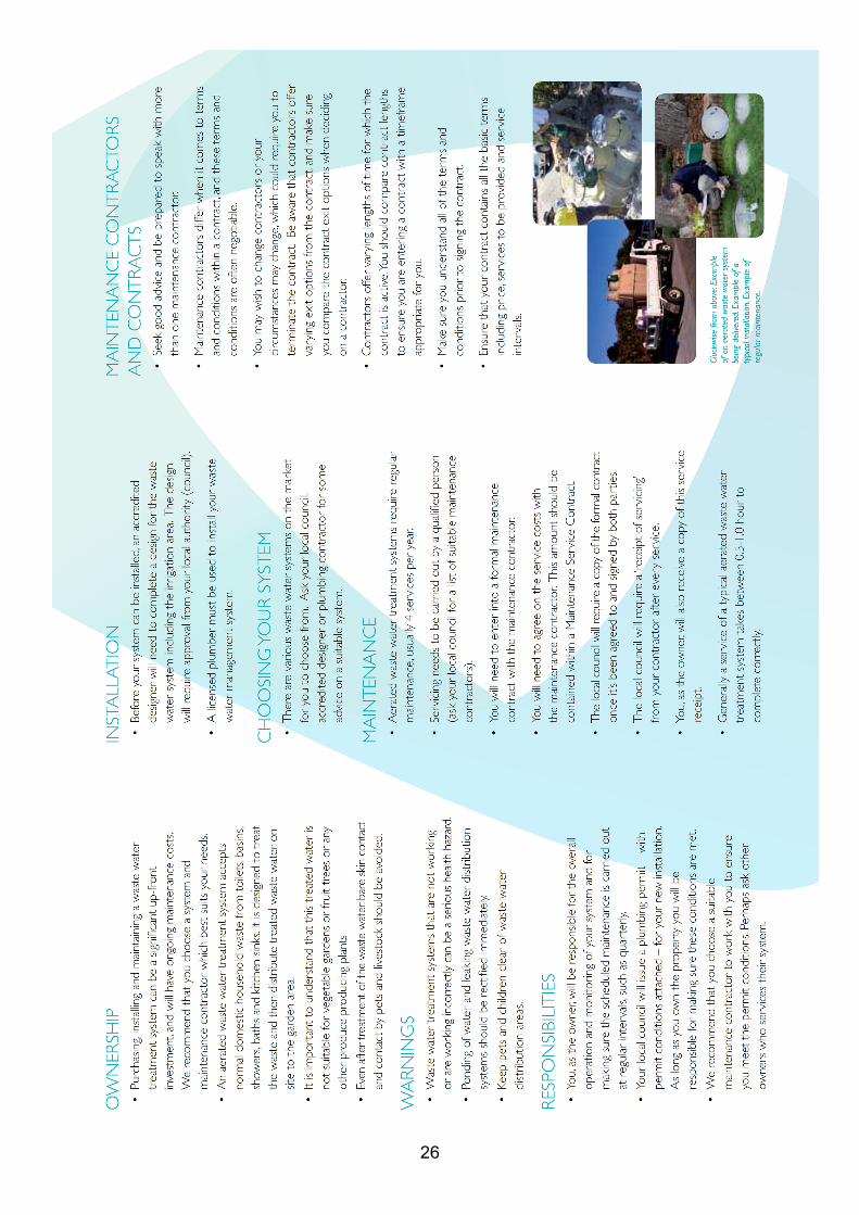
26