Site Preparation Guide - agilent.com · Site Preparation Guide 3 Contents 1 Agilent 8890 GC Site...
62
Agilent 8890 Gas Chromatograph Site Preparation Guide
Transcript of Site Preparation Guide - agilent.com · Site Preparation Guide 3 Contents 1 Agilent 8890 GC Site...
Agilent 8890 Gas Chromatograph
Site Preparation Guide
Site Preparation Guide
Notices© Agilent Technologies, Inc. 2019
No part of this manual may be reproduced in any form or by any means (including electronic storage and retrieval or translation into a foreign language) without prior agreement and written consent from Agilent Technologies, Inc. as governed by United States and international copyright laws.
Manual Part NumberG3540-90012
EditionFirst edition, January 2019Printed in USA
Agilent Technologies, Inc. 2850 Centerville Road Wilmington, DE 19808-1610 USA
安捷伦科技 (上海)有限公司上海市浦东新区外高桥保税区英伦路 412 号联系电话:(800)820 3278
WarrantyThe material contained in this document is provided “as is,” and is subject to being changed, without notice, in future editions. Further, to the maximum extent permitted by applicable law, Agilent disclaims all warranties, either express or implied, with regard to this manual and any information contained herein, including but not limited to the implied warranties of merchantability and fitness for a particular purpose. Agilent shall not be liable for errors or for incidental or consequential damages in connection with the furnishing, use, or performance of this document or of any information contained herein. Should Agilent and the user have a separate written agreement with warranty terms covering the material in this document that conflict with these terms, the warranty terms in the separate agreement shall control.
Technology Licenses The hardware and/or software described in this document are furnished under a license and may be used or copied only in accordance with the terms of such license.
Restricted Rights LegendU.S. Government Restricted Rights. Software and technical data rights granted to the federal government include only those rights customarily provided to end user customers. Agilent provides this customary commercial license in Software and technical data pursuant to FAR 12.211 (Technical Data) and 12.212 (Computer Software) and, for the Department of Defense, DFARS 252.227-7015 (Technical Data -Commercial Items) and DFARS 227.7202-3 (Rights in Commercial Computer Software or Computer Software Documentation).
Safety Notices
CAUTION
A CAUTION notice denotes a hazard. It calls attention to an operating procedure, practice, or the like that, if not correctly performed or adhered to, could result in damage to the product or loss of important data. Do not proceed beyond a CAUTION notice until the indicated conditions are fully understood and met.
WARNING
A WARNING notice denotes a hazard. It calls attention to an operating procedure, practice, or the like that, if not correctly performed or adhered to, could result in personal injury or death. Do not proceed beyond a WARNING notice until the indicated conditions are fully understood and met.
Site Preparation Guide 3
Contents
1 Agilent 8890 GC Site Preparation
Site Preparation Checklist 6
Bench Preparation 7
Maximum Length of Cables and Hoses 12
2 GC Installation Kits
Installation Kits 14
3 Dimensions and Weights
Dimensions and Weight 18
Foreline Pump Requirements for Systems Including an MSD 21
ALS Dimensions and Weight 22
4 Environmental Conditions
Environmental Conditions 24Heat Dissipation 25
ALS Environmental Conditions 26
5 Exhaust Venting
Exhaust Venting 28Venting hot air 28Venting other gases 29Exhaust vent fittings 30
6 GC System Power Requirements
Power Requirements 32USA fast heating oven, 240 V 34Canadian installation 34Common instrument power cord plugs 34
ALS Power Requirements 38
7 Gas Selection and Plumbing
Gas and Reagent Selection 40Hydrogen Carrier Gas 42Gas and Reagent Purity 42Gas Supplies 43
4 Site Preparation Guide
GC/MS Gas Requirements 45Performance verification 48
Gas Plumbing 49Supply tubing for most carrier and detector gases 50Supply tubing for hydrogen gas 50Two-stage pressure regulators 51Pressure regulator-gas supply tubing connections 51Filters and traps 52
8 Cryogenic Cooling Requirements
Cryogenic Cooling Requirements 56Using carbon dioxide 56Using liquid nitrogen 57Using compressed air 58
A LAN Requirements
Site LAN Network 60
Site Preparation Guide 5
1 Agilent 8890 GC Site PreparationSite Preparation Checklist 6
Bench Preparation 7
Maximum Length of Cables and Hoses 12
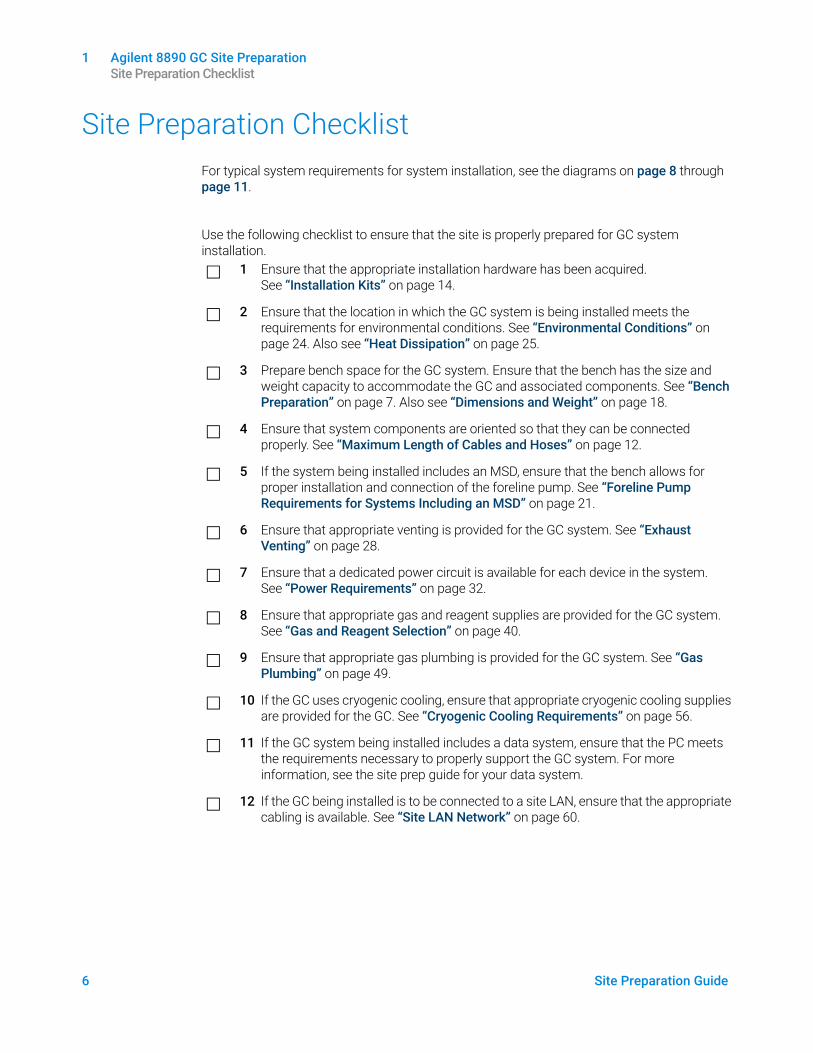
This guide outlines the site requirements for GC, GC/MS, and automatic liquid sampler (ALS) installation. Site requirements include the necessary space, electrical supplies, gas supplies, operating supplies and consumables required to successfully install the GC and related instruments and systems.
The site must meet the requirements specified in this guide before beginning installation.
Refer to the Agilent Web site at www.agilent.com for the most up-to-date listing of GC, GC/MS, and ALS supplies and consumables.
1 Agilent 8890 GC Site Preparation Site Preparation Checklist
6 Site Preparation Guide
Site Preparation ChecklistFor typical system requirements for system installation, see the diagrams on page 8 through page 11.
Use the following checklist to ensure that the site is properly prepared for GC system installation.
1 Ensure that the appropriate installation hardware has been acquired. See “Installation Kits” on page 14.
2 Ensure that the location in which the GC system is being installed meets the requirements for environmental conditions. See “Environmental Conditions” on page 24. Also see “Heat Dissipation” on page 25.
3 Prepare bench space for the GC system. Ensure that the bench has the size and weight capacity to accommodate the GC and associated components. See “Bench Preparation” on page 7. Also see “Dimensions and Weight” on page 18.
4 Ensure that system components are oriented so that they can be connected properly. See “Maximum Length of Cables and Hoses” on page 12.
5 If the system being installed includes an MSD, ensure that the bench allows for proper installation and connection of the foreline pump. See “Foreline Pump Requirements for Systems Including an MSD” on page 21.
6 Ensure that appropriate venting is provided for the GC system. See “Exhaust Venting” on page 28.
7 Ensure that a dedicated power circuit is available for each device in the system. See “Power Requirements” on page 32.
8 Ensure that appropriate gas and reagent supplies are provided for the GC system. See “Gas and Reagent Selection” on page 40.
9 Ensure that appropriate gas plumbing is provided for the GC system. See “Gas Plumbing” on page 49.
10 If the GC uses cryogenic cooling, ensure that appropriate cryogenic cooling supplies are provided for the GC. See “Cryogenic Cooling Requirements” on page 56.
11 If the GC system being installed includes a data system, ensure that the PC meets the requirements necessary to properly support the GC system. For more information, see the site prep guide for your data system.
12 If the GC being installed is to be connected to a site LAN, ensure that the appropriate cabling is available. See “Site LAN Network” on page 60.
1 Agilent 8890 GC Site Preparation Bench Preparation
Site Preparation Guide 7
Bench PreparationWhen planning a bench layout:
• Consider component dimensions, weights, and space requirements. See “Dimensions and Weight” on page 18.
• Consider the lengths of cables and hoses for connection of components. See “Maximum Length of Cables and Hoses” on page 12.
• For systems that include an MS, consider foreline pump requirements. See “Foreline Pump Requirements for Systems Including an MSD” on page 21.
• Allow space for operational access.
• Note that the 7200 Q-TOF requires 48 cm (1.6 ft) of space in front to allow for the RIS probe extraction tool handle when installed.
• Note that some repairs to the GC/MS, or to the GC itself, will require access to the back of the instrument(s).
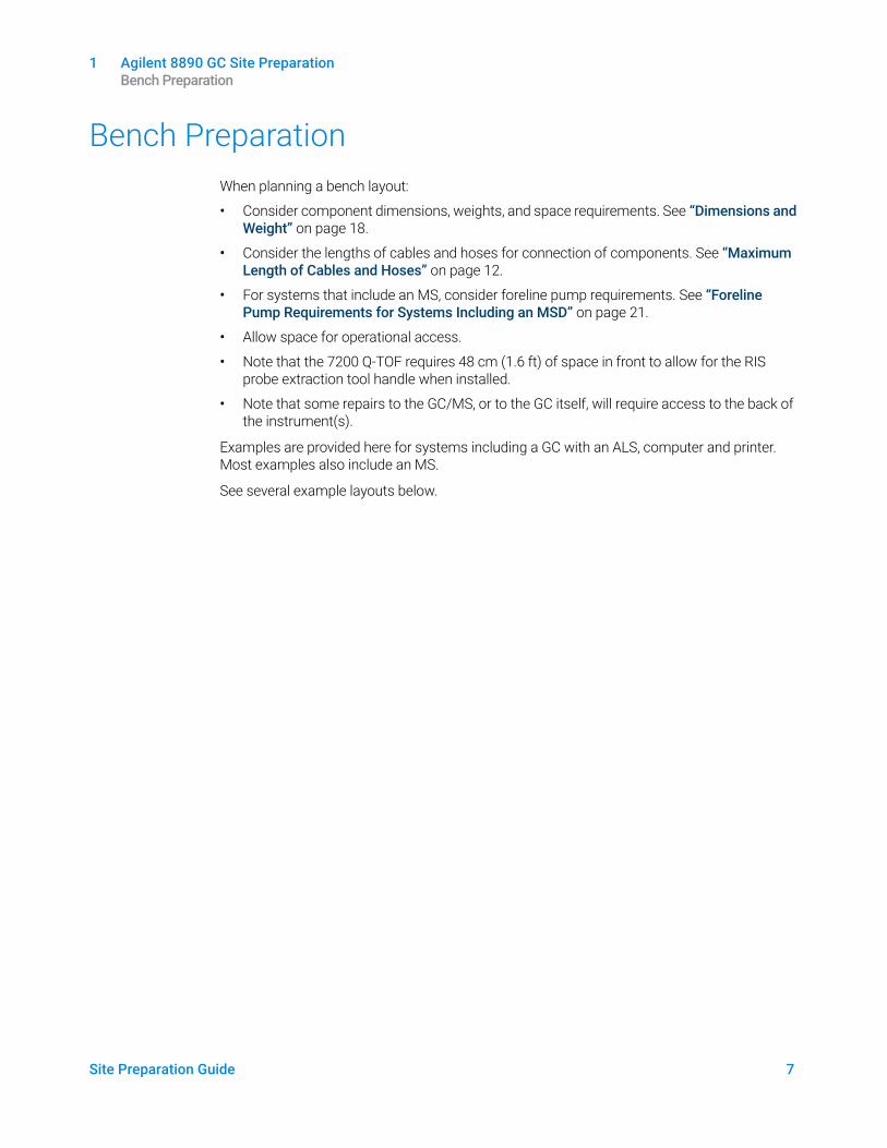
Examples are provided here for systems including a GC with an ALS, computer and printer. Most examples also include an MS.
See several example layouts below.
8 Site Preparation Guide
1 Agilent 8890 GC Site Preparation Bench Preparation
Typi
cal G
C Sy
stem
- 88
90 G
C w
ith c
ompu
ter a
nd p
rinte
r.
Tota
l wei
ght:
~84
kg (1
86 lb
) M
axim
um p
ower
con
sum
ptio
n: ~
3,95
0 VA
(13,
478
btu/
hr)
78 c
m (3
1-in
.) (w
ithou
t hea
t de
flect
or)
65 c
m (2
6-in
.) (w
ith
heat
def
lect
or)
Leav
e 30
cm
(12-
in.)
open
spa
ce fo
r op
erat
iona
l acc
ess
Use
dedi
cate
d ci
rcui
ts fo
r GC
and
MSD
.
Appl
icat
ion
Gas
*
*Us
e 1/
8-in
Sw
agel
ok g
as c
onne
ctio
ns
Purit
y
Supp
ly
Pres
sure
(p
si)†
†1
psi =
6.8
9 kP
a
Carri
erH
eliu
m
Hyd
roge
n N
itrog
en
99.9
995
99.9
995
99.9
995
50 -
80
50 -
80
50 -
80
Dete
ctor
s
TCD
Hel
ium
99.9
995
50 -
80
FID,
NPD
, FP
D, T
CDH
ydro
gen
99.9
995
50 -
80
ECD,
FID
, FP
D, N
PD,
TCD
Nitr
ogen
99.9
995
50 -
80
FID,
NPD
, FP
DAi
rZe
ro
grad
e50
- 80
Cryo
Coo
ling
(Liq
uid)
Tubi
ng
Supp
ly
Pres
sure
(p
si)*
*1
psi =
6.8
9 kP
a
CO2
1/8-
inch
sta
inle
ss tu
bing
700-
900
N2
1/4-
inch
insu
late
d tu
bing
20-2
5
80 c
m
(32-
in.)
(with
out
ALS)
100
cm (4
0-in
.) (w
ith A
LS)
~2.3
5 m
(7.7
ft.)
~86
cm (3
4-in
.)~5
6 cm
(22-
in.)
~56
cm (2
2-in
.)~4
4 cm
(17.
3-in
.)
1 Agilent 8890 GC Site Preparation Bench Preparation
Site Preparation Guide 9
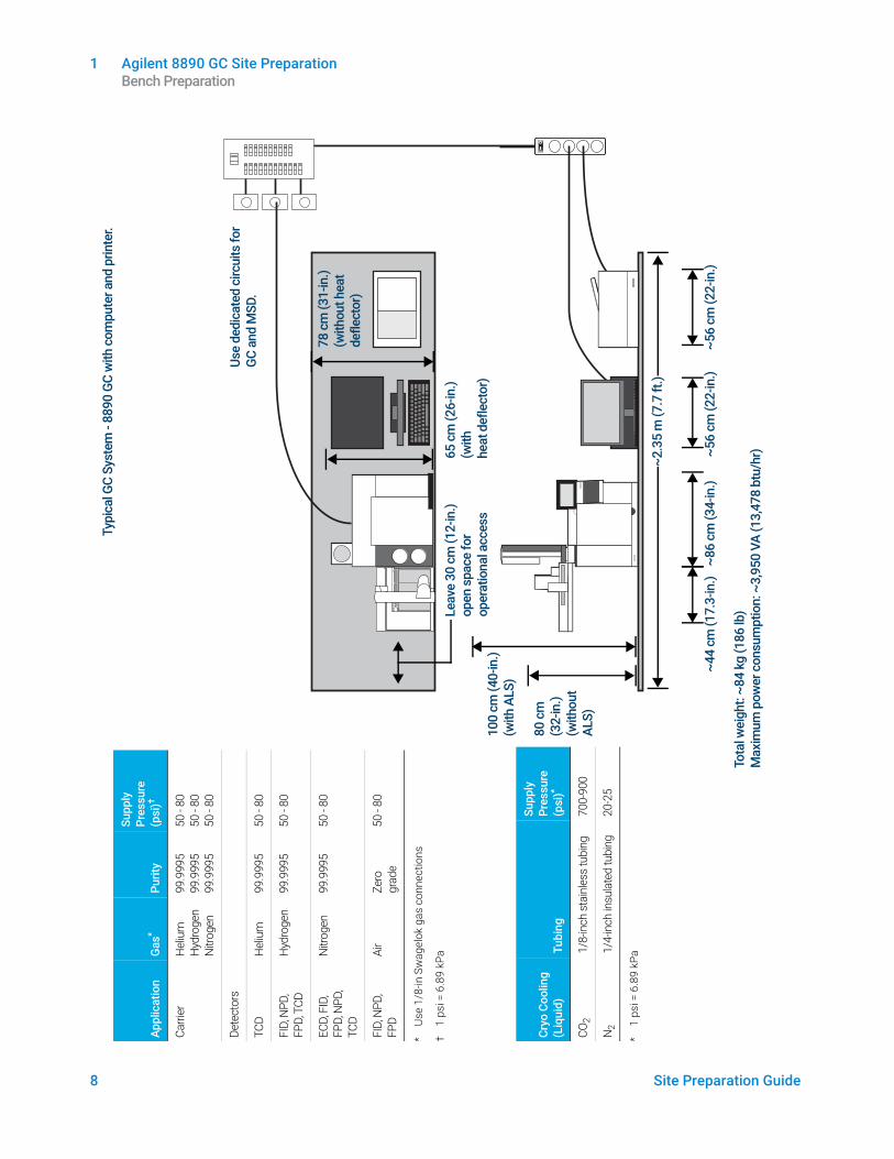
Typi
cal G
C/M
S Sy
stem
- 88
90 G
C, 5
977
MSD
, with
com
pute
r and
pr
inte
r.
Tota
l wei
ght:
~123
kg
(271
lb)
Max
imum
pow
er c
onsu
mpt
ion:
~5,
050
VA (1
7,23
2 bt
u/hr
)
78 c
m (3
1-in
.) (w
ithou
t hea
t de
flect
or)
65 c
m (2
6-in
.) (w
ith h
eat
defle
ctor
)
If be
nch
back
s up
to
wal
l, dril
l 1.5
-in. h
ole
for f
orel
ine
pum
p ho
se.
Leav
e 30
cm
(12-
in.)
open
sp
ace
for o
pera
tiona
l ac
cess
Use
dedi
cate
d ci
rcui
ts fo
r GC
and
MSD
.
Plac
e fo
relin
e pu
mp
on fl
oor o
r on
vib
ratio
n re
duci
ng b
ench
.
Appl
icat
ion
Gas
*
*Us
e 1/
8-in
Sw
agel
ok g
as c
onne
ctio
ns
Purit
y
Supp
ly
Pres
sure
(p
si)†
†1
psi =
6.8
9 kP
a
Carri
erH
eliu
m
Hyd
roge
n N
itrog
en
99.9
995
99.9
995
99.9
995
50 -
80
50 -
80
50 -
80
Dete
ctor
s
TCD
Hel
ium
99.9
995
50 -
80
FID,
NPD
, FP
D, T
CDH
ydro
gen
99.9
995
50 -
80
ECD,
FID
, FP
D, N
PD,
TCD
Nitr
ogen
99.9
995
50 -
80
FID,
NPD
, FP
DAi
rZe
ro
grad
e50
- 80
Cryo
Coo
ling
(Liq
uid)
Tubi
ng
Supp
ly
Pres
sure
(p
si)*
*1
psi =
6.8
9 kP
a
CO2
1/8-
inch
sta
inle
ss tu
bing
700-
900
N2
1/4-
inch
insu
late
d tu
bing
20-2
5
80 c
m
(32-
in.)
(with
out
ALS)
100
cm (4
0-in
.) (w
ith A
LS)
~2.3
5 m
(7.7
ft.)
~86
cm (3
4-in
.)~5
6 cm
(22-
in.)
~56
cm (2
2-in
.)~4
4 cm
(17.
3-in
.)
10 Site Preparation Guide
1 Agilent 8890 GC Site Preparation Bench Preparation
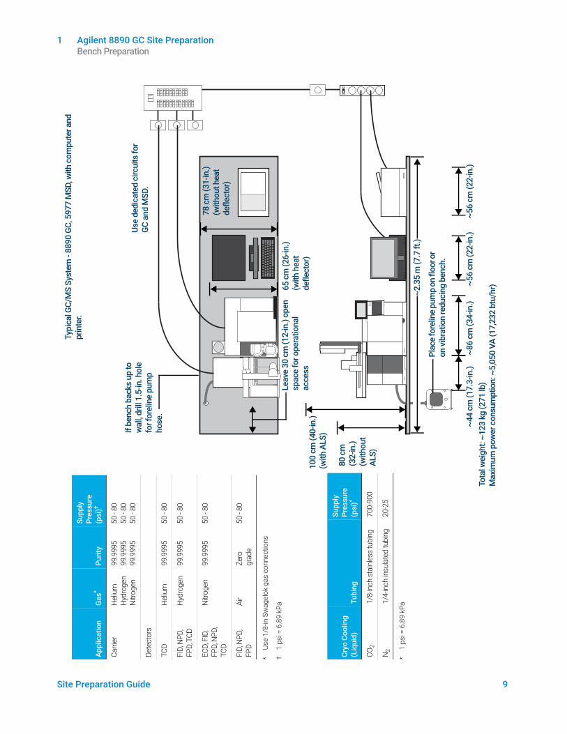
Typi
cal G
C/M
S Sy
stem
- 88
90 G
C, 7
000
or 7
010
MSD
, with
co
mpu
ter a
nd p
rinte
r.
Tota
l wei
ght:
~142
kg
(311
lb)
Max
imum
pow
er c
onsu
mpt
ion:
~5,
550
VA (1
8,93
8 bt
u/hr
)
78 c
m (3
1-in
.) (w
ithou
t hea
t de
flect
or)
65 c
m (2
6-in
.) (w
ith h
eat
defle
ctor
)
If be
nch
back
s up
to
wal
l, dril
l 1.5
-in. h
ole
for f
orel
ine
pum
p ho
se.
Leav
e 30
cm
(12-
in.)
open
sp
ace
for o
pera
tiona
l ac
cess
Use
dedi
cate
d ci
rcui
ts fo
r GC
and
MSD
.
Plac
e fo
relin
e pu
mp
on fl
oor o
r on
vib
ratio
n re
duci
ng b
ench
.
Appl
icat
ion
Gas
*
*Us
e 1/
8-in
Sw
agel
ok g
as c
onne
ctio
ns
Purit
y
Supp
ly
Pres
sure
(p
si)†
†1
psi =
6.8
9 kP
a
Carri
erH
eliu
m
Hyd
roge
n N
itrog
en
99.9
995
99.9
995
99.9
995
50 -
80
50 -
80
50 -
80
Dete
ctor
s
TCD
Hel
ium
99.9
995
50 -
80
FID,
NPD
, FP
D, T
CDH
ydro
gen
99.9
995
50 -
80
ECD,
FID
, FP
D, N
PD,
TCD
Nitr
ogen
99.9
995
50 -
80
FID,
NPD
, FP
DAi
rZe
ro
grad
e50
- 80
Cryo
Coo
ling
(Liq
uid)
Tubi
ng
Supp
ly
Pres
sure
(p
si)*
*1
psi =
6.8
9 kP
a
CO2
1/8-
inch
sta
inle
ss tu
bing
700-
900
N2
1/4-
inch
insu
late
d tu
bing
20-2
5
80 c
m
(32-
in.)
(with
out
ALS)
100
cm
(40-
in.)
(with
ALS
)
~2.3
5 m
(7.7
ft.)
~86
cm (3
4-in
.)~5
6 cm
(22-
in.)
~56
cm (2
2-in
.)~4
4 cm
(17.
3-in
.)
1 Agilent 8890 GC Site Preparation Bench Preparation
Site Preparation Guide 11
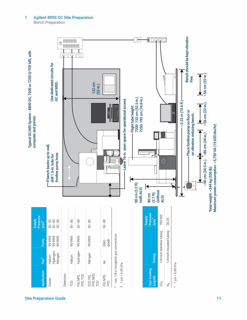
Typi
cal G
C/M
S Sy
stem
- 88
90 G
C, 7
200
or 7
250
Q-TO
F M
S, w
ith
com
pute
r and
prin
ter.
Tota
l wei
ght:
~244
kg
(536
lb)
Max
imum
pow
er c
onsu
mpt
ion:
~5,
750
VA (1
9,62
0 bt
u/hr
)
132
cm
(5
2-in
.)
If be
nch
back
s up
to w
all,
drill
1.5
-in. h
ole
for
fore
line
pum
p ho
se.
Leav
e 16
-in. o
pen
spac
e fo
r ope
ratio
nal a
cces
sUse
dedi
cate
d ci
rcui
ts fo
r GC
and
MSD
.
Plac
e fo
relin
e pu
mp
on fl
oor o
r on
vib
ratio
n re
duci
ng b
ench
.
Appl
icat
ion
Gas
*
*Us
e 1/
8-in
Sw
agel
ok g
as c
onne
ctio
ns
Purit
y
Supp
ly
Pres
sure
(p
si)†
†1
psi =
6.8
9 kP
a
Carri
erH
eliu
m
Hyd
roge
n N
itrog
en
99.9
995
99.9
995
99.9
995
50 -
80
50 -
80
50 -
80
Dete
ctor
s
TCD
Hel
ium
99.9
995
50 -
80
FID,
NPD
, FP
D, T
CDH
ydro
gen
99.9
995
50 -
80
ECD,
FID
, FP
D, N
PD,
TCD
Nitr
ogen
99.9
995
50 -
80
FID,
NPD
, FP
DAi
rZe
ro
grad
e50
- 80
Cryo
Coo
ling
(Liq
uid)
Tubi
ng
Supp
ly
Pres
sure
(p
si)*
*1
psi =
6.8
9 kP
a
CO2
1/8-
inch
sta
inle
ss tu
bing
700-
900
N2
1/4-
inch
insu
late
d tu
bing
20-2
5
80 c
m
(2.7
ft)
(with
out
ALS)
98 c
m (3
.2 ft
) (w
ith A
LS)
~3.2
3 m
(10.
6 ft.
)
Flig
ht tu
be h
eigh
t: 72
00: 1
33 c
m (5
2.5-
in.)
7250
: 190
cm
(74.
8-in
.)
Benc
h sh
ould
be
kept
vibr
atio
n fre
e.
~86
cm (3
4-in
.)~5
6 cm
(22-
in.)
~56
cm (2
2-in
.)~9
0 cm
(34.
5-in
.)
1 Agilent 8890 GC Site Preparation Maximum Length of Cables and Hoses
12 Site Preparation Guide
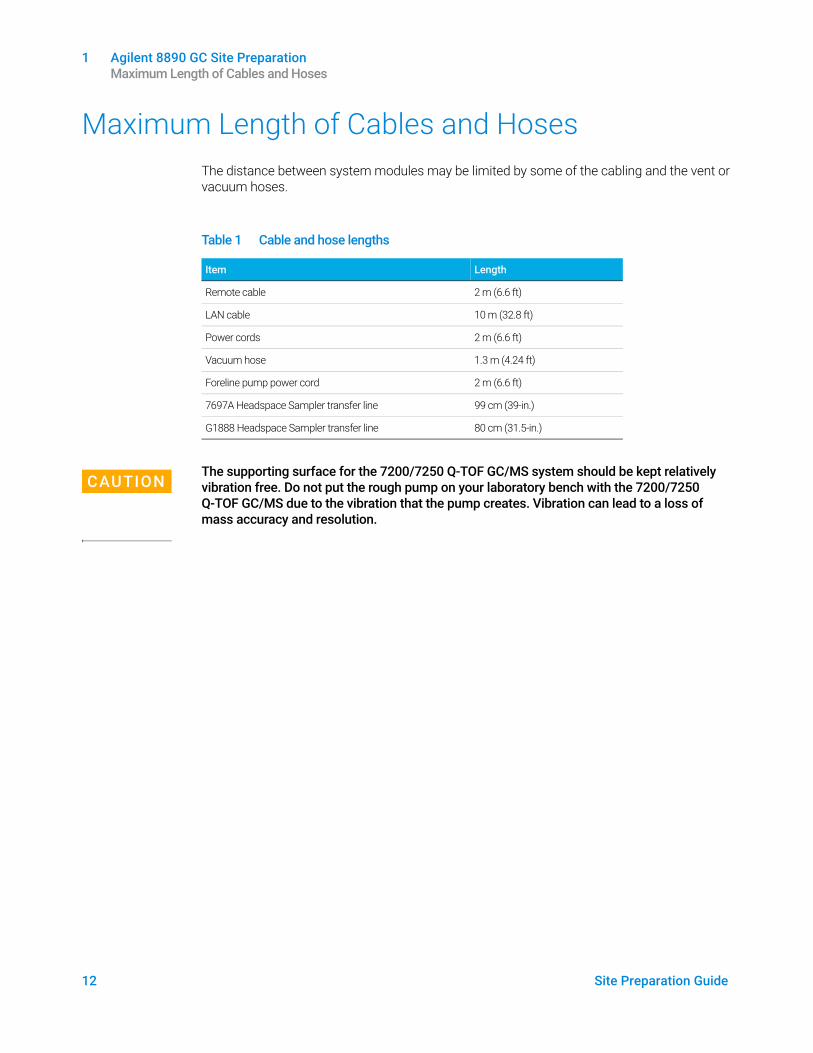
Maximum Length of Cables and HosesThe distance between system modules may be limited by some of the cabling and the vent or vacuum hoses.
CAUTIONThe supporting surface for the 7200/7250 Q-TOF GC/MS system should be kept relatively vibration free. Do not put the rough pump on your laboratory bench with the 7200/7250 Q-TOF GC/MS due to the vibration that the pump creates. Vibration can lead to a loss of mass accuracy and resolution.
Table 1 Cable and hose lengths
Item Length
Remote cable 2 m (6.6 ft)
LAN cable 10 m (32.8 ft)
Power cords 2 m (6.6 ft)
Vacuum hose 1.3 m (4.24 ft)
Foreline pump power cord 2 m (6.6 ft)
7697A Headspace Sampler transfer line 99 cm (39-in.)
G1888 Headspace Sampler transfer line 80 cm (31.5-in.)
Site Preparation Guide 13
2 GC Installation KitsInstallation Kits 14
This section provides details for available installation hardware.
Refer to the Agilent Web site at www.agilent.com for the most up-to-date listing of GC, GC/MS, and ALS supplies and consumables.
2 GC Installation Kits Installation Kits
14 Site Preparation Guide
Installation Kits
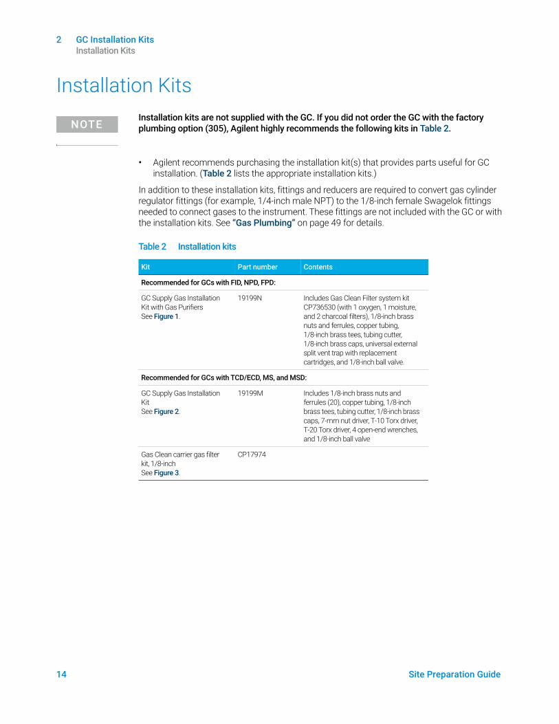
NOTEInstallation kits are not supplied with the GC. If you did not order the GC with the factory plumbing option (305), Agilent highly recommends the following kits in Table 2.
• Agilent recommends purchasing the installation kit(s) that provides parts useful for GC installation. (Table 2 lists the appropriate installation kits.)
In addition to these installation kits, fittings and reducers are required to convert gas cylinder regulator fittings (for example, 1/4-inch male NPT) to the 1/8-inch female Swagelok fittings needed to connect gases to the instrument. These fittings are not included with the GC or with the installation kits. See “Gas Plumbing” on page 49 for details.
Table 2 Installation kits
Kit Part number Contents
Recommended for GCs with FID, NPD, FPD:
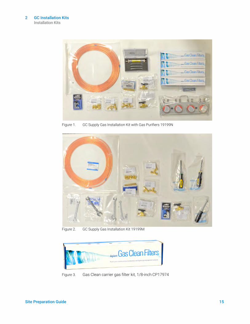
GC Supply Gas Installation Kit with Gas Purifiers See Figure 1.
19199N Includes Gas Clean Filter system kit CP736530 (with 1 oxygen, 1 moisture, and 2 charcoal filters), 1/8-inch brass nuts and ferrules, copper tubing, 1/8-inch brass tees, tubing cutter, 1/8-inch brass caps, universal external split vent trap with replacement cartridges, and 1/8-inch ball valve.
Recommended for GCs with TCD/ECD, MS, and MSD:
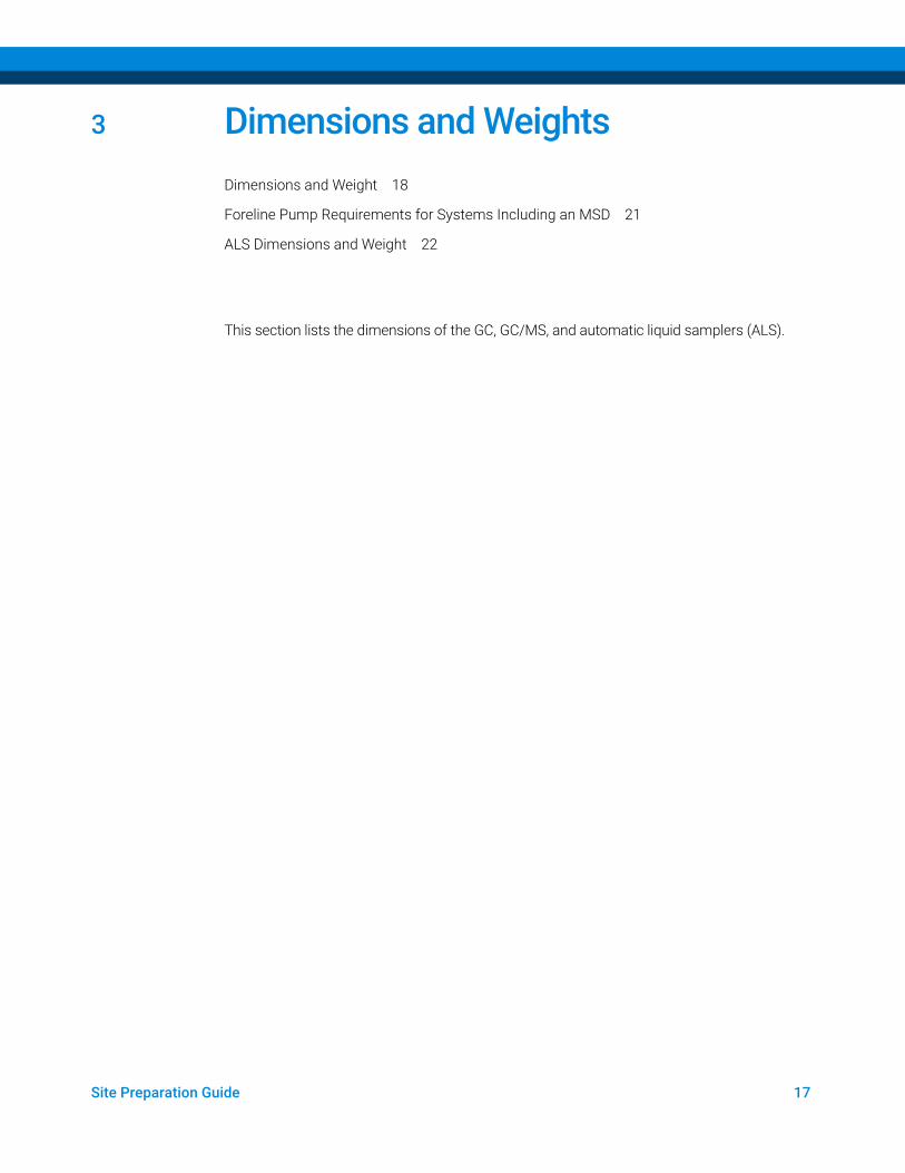
GC Supply Gas Installation Kit See Figure 2.
19199M Includes 1/8-inch brass nuts and ferrules (20), copper tubing, 1/8-inch brass tees, tubing cutter, 1/8-inch brass caps, 7-mm nut driver, T-10 Torx driver, T-20 Torx driver, 4 open-end wrenches, and 1/8-inch ball valve
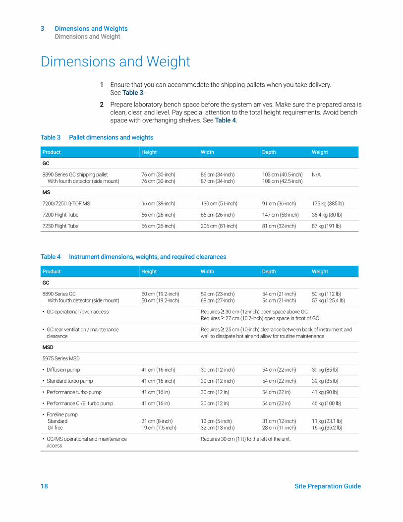
Gas Clean carrier gas filter kit, 1/8-inch See Figure 3.
CP17974
2 GC Installation Kits Installation Kits
Site Preparation Guide 15
Figure 1. GC Supply Gas Installation Kit with Gas Purifiers 19199N
Figure 2. GC Supply Gas Installation Kit 19199M
Figure 3. Gas Clean carrier gas filter kit, 1/8-inch CP17974

2 GC Installation Kits Installation Kits
16 Site Preparation Guide
Site Preparation Guide 17
3 Dimensions and WeightsDimensions and Weight 18
Foreline Pump Requirements for Systems Including an MSD 21
ALS Dimensions and Weight 22
This section lists the dimensions of the GC, GC/MS, and automatic liquid samplers (ALS).
3 Dimensions and Weights Dimensions and Weight
18 Site Preparation Guide
Dimensions and Weight1 Ensure that you can accommodate the shipping pallets when you take delivery.
See Table 3.
2 Prepare laboratory bench space before the system arrives. Make sure the prepared area is clean, clear, and level. Pay special attention to the total height requirements. Avoid bench space with overhanging shelves. See Table 4.
Table 3 Pallet dimensions and weights
Product Height Width Depth Weight
GC
8890 Series GC shipping palletWith fourth detector (side mount)
76 cm (30-inch)76 cm (30-inch)
86 cm (34-inch)87 cm (34-inch)
103 cm (40.5-inch)108 cm (42.5-inch)
N/A
MS
7200/7250 Q-TOF MS 96 cm (38-inch) 130 cm (51-inch) 91 cm (36-inch) 175 kg (385 lb)
7200 Flight Tube 66 cm (26-inch) 66 cm (26-inch) 147 cm (58-inch) 36.4 kg (80 lb)
7250 Flight Tube 66 cm (26-inch) 206 cm (81-inch) 81 cm (32-inch) 87 kg (191 lb)
Table 4 Instrument dimensions, weights, and required clearances
Product Height Width Depth Weight
GC
8890 Series GCWith fourth detector (side mount)
50 cm (19.2-inch)50 cm (19.2-inch)
59 cm (23-inch)68 cm (27-inch)
54 cm (21-inch)54 cm (21-inch)
50 kg (112 lb)57 kg (125.4 lb)
• GC operational /oven access Requires ≥ 30 cm (12-inch) open space above GC. Requires ≥ 27 cm (10.7-inch) open space in front of GC.
• GC rear ventilation / maintenance clearance
Requires ≥ 25 cm (10-inch) clearance between back of instrument and wall to dissipate hot air and allow for routine maintenance.
MSD
5975 Series MSD
• Diffusion pump 41 cm (16-inch) 30 cm (12-inch) 54 cm (22-inch) 39 kg (85 lb)
• Standard turbo pump 41 cm (16-inch) 30 cm (12-inch) 54 cm (22-inch) 39 kg (85 lb)
• Performance turbo pump 41 cm (16 in) 30 cm (12 in) 54 cm (22 in) 41 kg (90 lb)
• Performance CI/EI turbo pump 41 cm (16 in) 30 cm (12 in) 54 cm (22 in) 46 kg (100 lb)
• Foreline pumpStandard Oil-free
21 cm (8-inch)19 cm (7.5-inch)
13 cm (5-inch)32 cm (13-inch)
31 cm (12-inch)28 cm (11-inch)
11 kg (23.1 lb)16 kg (35.2 lb)
• GC/MS operational and maintenance access
Requires 30 cm (1 ft) to the left of the unit.
3 Dimensions and Weights Dimensions and Weight
Site Preparation Guide 19
5977 Series MSD
• Diffusion pump 41 cm (16-inch) 30 cm (12-inch) 54 cm (22-inch) 39 kg (85 lb)
• Performance turbo pump 41 cm (16-inch) 30 cm (12-inch) 54 cm (22-inch) 41 kg (90 lb)
• Performance CI/EI turbo pump 41 cm (16 in) 30 cm (12 in) 54 cm (22 in) 46 kg (100 lb)
• Foreline pumpStandard Oil-free (MVP-070)Oil-free (IDP3)
21 cm (8-inch)19 cm (7.5-inch)18 cm (7-inch)
13 cm (5-inch)32 cm (13-inch)35 cm (14-incn)
31 cm (12-inch)28 cm (11-inch)14 cm (6-inch)
11 kg (23.1 lb)16 kg (35.2 lb)10 kg (21 lb)
• GC/MS operational and maintenance access
Requires 30 cm (1 ft) to the left of the unit.
MS
7000 and 7010 Triple Quad MS
• EI Mainframe 47 cm (18.5-inch) 35 cm (14-inch) 86 cm (34-inch) 59 kg (130 lb)
• EI/CI Mainframe 47 cm (18.5-inch) 35 cm (14-inch) 86 cm (34-inch) 63.5 kg (140 lb)
• Foreline pump 28 cm (11-inch) 18 cm (7-inch) 35 cm (14-inch) 21.5 kg (47.3 lb)
• GC/MS operational and maintenance access
Requires 30 cm (1 ft) to the left of the unit.
7200 Q-TOF MS
• Mainframe 133 cm (52.5-inch) 90 cm (34.5-inch) 100 cm (39.5-inch) 138 kg (305 lb)
• Foreline pump 28 cm (11-inch) 18 cm (7-inch) 35 cm (14-inch) 21.5 kg (47.3 lb)
7250 Q-TOF MS
• Mainframe 190 cm (74.8-inch) 90 cm (34.5-inch) 100 cm (39.5-inch) 138 kg (350 lb)
• Foreline pump DS202 28 cm (11-inch) 18 cm (7-inch) 35 cm (14-inch) 21.5 kg (47.3 lb)
• Foreline pump IDP-15 36.4 cm (14.3-inch) 33.3 cm (13.1-inch) 48.5 cm (19.1-inch) 45.5 kg (100 lb)
• GC/Q-TOF operational and maintenance access
Requires 40 cm (16-inch) clearance on both sides of the unit. Requires 30 cm (12-inch) clearance behind the unit.
Headspace sampler (HS)
7697A Headspace sampler111 vial model12 vial model
80 cm (32-inch)61 cm (24-inch)
69 cm (27-inch)64 cm (25-inch)
70 cm (27.5-inch)69 cm (27-inch)
46 kg (101 lb)38.2 kg (84 lb)
• GC with 7697A Headspace sampler Requires 69 cm (27-inch) to the right of the GC (G4557A), or 64 cm (25-inch) to the right of the GC (G4556A).
G1888 Headspace sampler 56 cm (22-inch) 46 cm (18.1-inch) 64 cm (25-inch) 46.3 kg (102 lb)
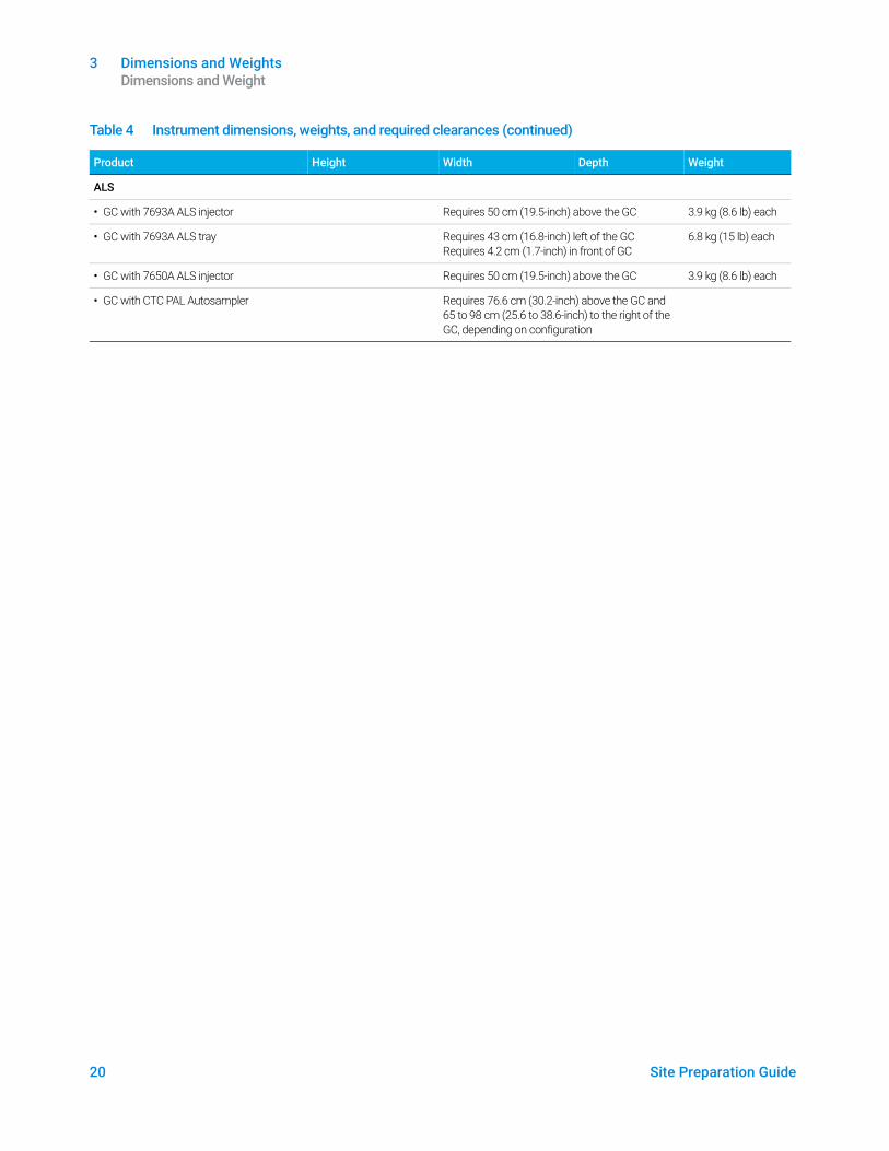
Table 4 Instrument dimensions, weights, and required clearances (continued)
Product Height Width Depth Weight
3 Dimensions and Weights Dimensions and Weight
20 Site Preparation Guide
ALS
• GC with 7693A ALS injector Requires 50 cm (19.5-inch) above the GC 3.9 kg (8.6 lb) each
• GC with 7693A ALS tray Requires 43 cm (16.8-inch) left of the GC Requires 4.2 cm (1.7-inch) in front of GC
6.8 kg (15 lb) each
• GC with 7650A ALS injector Requires 50 cm (19.5-inch) above the GC 3.9 kg (8.6 lb) each
• GC with CTC PAL Autosampler Requires 76.6 cm (30.2-inch) above the GC and 65 to 98 cm (25.6 to 38.6-inch) to the right of the GC, depending on configuration
Table 4 Instrument dimensions, weights, and required clearances (continued)
Product Height Width Depth Weight
3 Dimensions and Weights Foreline Pump Requirements for Systems Including an MSD
Site Preparation Guide 21
Foreline Pump Requirements for Systems Including an MSD
1 If using a 7200 or 7250 Q-TOF MS, the length of the quadrupole vacuum hose is 130 cm (4 ft 3-inch) from the high vacuum pump to the foreline pump, and the length of the foreline pump power cord is 2 m (6 ft 6-inch).
2 If your bench abuts a wall, drill 4 cm (1.5-inch) diameter holes through the rear of the bench for the vacuum hose and power cord.
CAUTIONMake sure the 7200/7250 Q-TOF GC/MS foreline pump is located where it is not likely to be touched by operators.
3 Dimensions and Weights ALS Dimensions and Weight
22 Site Preparation Guide
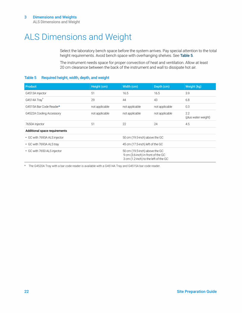
ALS Dimensions and WeightSelect the laboratory bench space before the system arrives. Pay special attention to the total height requirements. Avoid bench space with overhanging shelves. See Table 5.
The instrument needs space for proper convection of heat and ventilation. Allow at least 20 cm clearance between the back of the instrument and wall to dissipate hot air.
Table 5 Required height, width, depth, and weight
Product Height (cm) Width (cm) Depth (cm) Weight (kg)
G4513A Injector 51 16.5 16.5 3.9
G4514A Tray* 29 44 43 6.8
G4515A Bar Code Reader* not applicable not applicable not applicable 0.3
G4522A Cooling Accessory not applicable not applicable not applicable 2.2 (plus water weight)
7650A Injector 51 22 24 4.5
Additional space requirements
• GC with 7693A ALS injector 50 cm (19.5-inch) above the GC
• GC with 7693A ALS tray 45 cm (17.5-inch) left of the GC
• GC with 7650 ALS injector 50 cm (19.5-inch) above the GC 9 cm (3.6-inch) in front of the GC 3 cm (1.2-inch) to the left of the GC
* The G4520A Tray with a bar code reader is available with a G4514A Tray and G4515A bar code reader.
Site Preparation Guide 23
4 Environmental ConditionsEnvironmental Conditions 24
Heat Dissipation 25
ALS Environmental Conditions 26
This section outlines the environmental requirements for use or storage of the GC, GC/MS, and automatic liquid sampler (ALS). Heat dissipation information is also provided.
4 Environmental Conditions Environmental Conditions
24 Site Preparation Guide
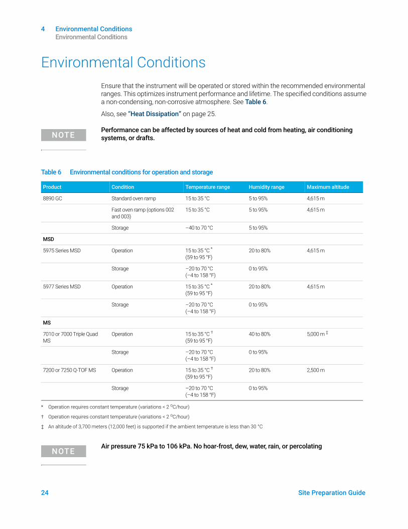
Environmental ConditionsEnsure that the instrument will be operated or stored within the recommended environmental ranges. This optimizes instrument performance and lifetime. The specified conditions assume a non-condensing, non-corrosive atmosphere. See Table 6.
Also, see “Heat Dissipation” on page 25.
NOTEPerformance can be affected by sources of heat and cold from heating, air conditioning systems, or drafts.
NOTEAir pressure 75 kPa to 106 kPa. No hoar-frost, dew, water, rain, or percolating
Table 6 Environmental conditions for operation and storage
Product Condition Temperature range Humidity range Maximum altitude
8890 GC Standard oven ramp 15 to 35 °C 5 to 95% 4,615 m
Fast oven ramp (options 002 and 003)
15 to 35 °C 5 to 95% 4,615 m
Storage –40 to 70 °C 5 to 95%
MSD
5975 Series MSD Operation 15 to 35 °C * (59 to 95 °F)
20 to 80% 4,615 m
Storage –20 to 70 °C (–4 to 158 °F)
0 to 95%
5977 Series MSD Operation 15 to 35 °C * (59 to 95 °F)
20 to 80% 4,615 m
Storage –20 to 70 °C (–4 to 158 °F)
0 to 95%
MS
7010 or 7000 Triple Quad MS
Operation 15 to 35 °C † (59 to 95 °F)
40 to 80% 5,000 m ‡
Storage –20 to 70 °C (–4 to 158 °F)
0 to 95%
7200 or 7250 Q-TOF MS Operation 15 to 35 °C †
(59 to 95 °F)20 to 80% 2,500 m
Storage –20 to 70 °C (–4 to 158 °F)
0 to 95%
* Operation requires constant temperature (variations < 2 oC/hour)
† Operation requires constant temperature (variations < 2 oC/hour)
‡ An altitude of 3,700 meters (12,000 feet) is supported if the ambient temperature is less than 30 °C
4 Environmental Conditions Heat Dissipation
Site Preparation Guide 25
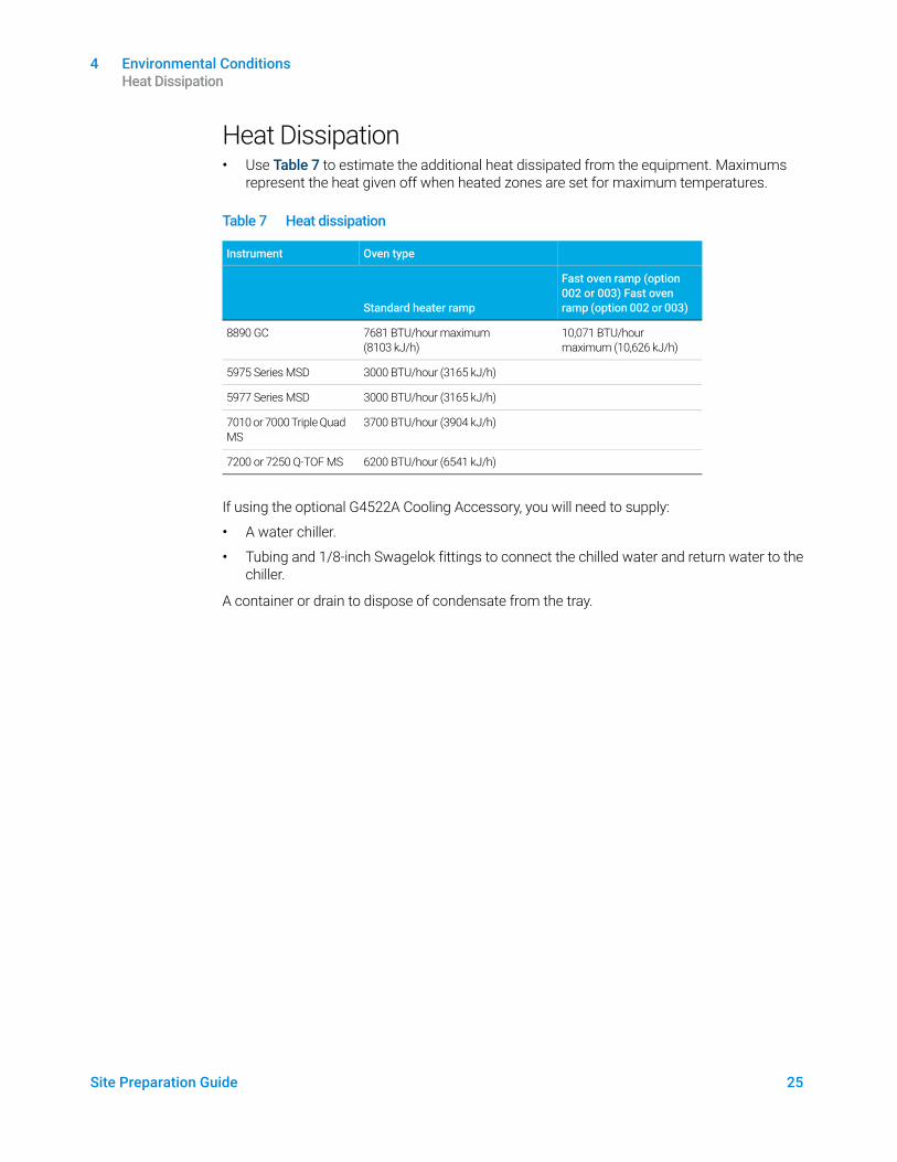
Heat Dissipation• Use Table 7 to estimate the additional heat dissipated from the equipment. Maximums
represent the heat given off when heated zones are set for maximum temperatures.
If using the optional G4522A Cooling Accessory, you will need to supply:
• A water chiller.
• Tubing and 1/8-inch Swagelok fittings to connect the chilled water and return water to the chiller.
A container or drain to dispose of condensate from the tray.
Table 7 Heat dissipation
Instrument Oven type
Standard heater ramp
Fast oven ramp (option 002 or 003) Fast oven ramp (option 002 or 003)
8890 GC 7681 BTU/hour maximum (8103 kJ/h)
10,071 BTU/hour maximum (10,626 kJ/h)
5975 Series MSD 3000 BTU/hour (3165 kJ/h)
5977 Series MSD 3000 BTU/hour (3165 kJ/h)
7010 or 7000 Triple Quad MS
3700 BTU/hour (3904 kJ/h)
7200 or 7250 Q-TOF MS 6200 BTU/hour (6541 kJ/h)
4 Environmental Conditions ALS Environmental Conditions
26 Site Preparation Guide
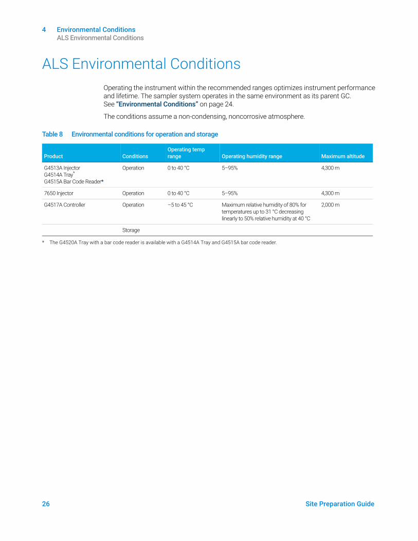
ALS Environmental ConditionsOperating the instrument within the recommended ranges optimizes instrument performance and lifetime. The sampler system operates in the same environment as its parent GC. See “Environmental Conditions” on page 24.
The conditions assume a non-condensing, noncorrosive atmosphere.
Table 8 Environmental conditions for operation and storage
Product
Conditions
Operating temp range
Operating humidity range
Maximum altitude
G4513A Injector G4514A Tray* G4515A Bar Code Reader*
Operation 0 to 40 °C 5–95% 4,300 m
7650 Injector Operation 0 to 40 °C 5–95% 4,300 m
G4517A Controller Operation –5 to 45 °C Maximum relative humidity of 80% for temperatures up to 31 °C decreasing linearly to 50% relative humidity at 40 °C
2,000 m
Storage
* The G4520A Tray with a bar code reader is available with a G4514A Tray and G4515A bar code reader.
Site Preparation Guide 27
5 Exhaust VentingExhaust Venting 28
Venting hot air 28Venting other gases 29Exhaust vent fittings 30
This section outlines the exhaust venting requirements for GC, GC/MS, and automatic liquid sampler (ALS) installation.
5 Exhaust Venting Exhaust Venting
28 Site Preparation Guide
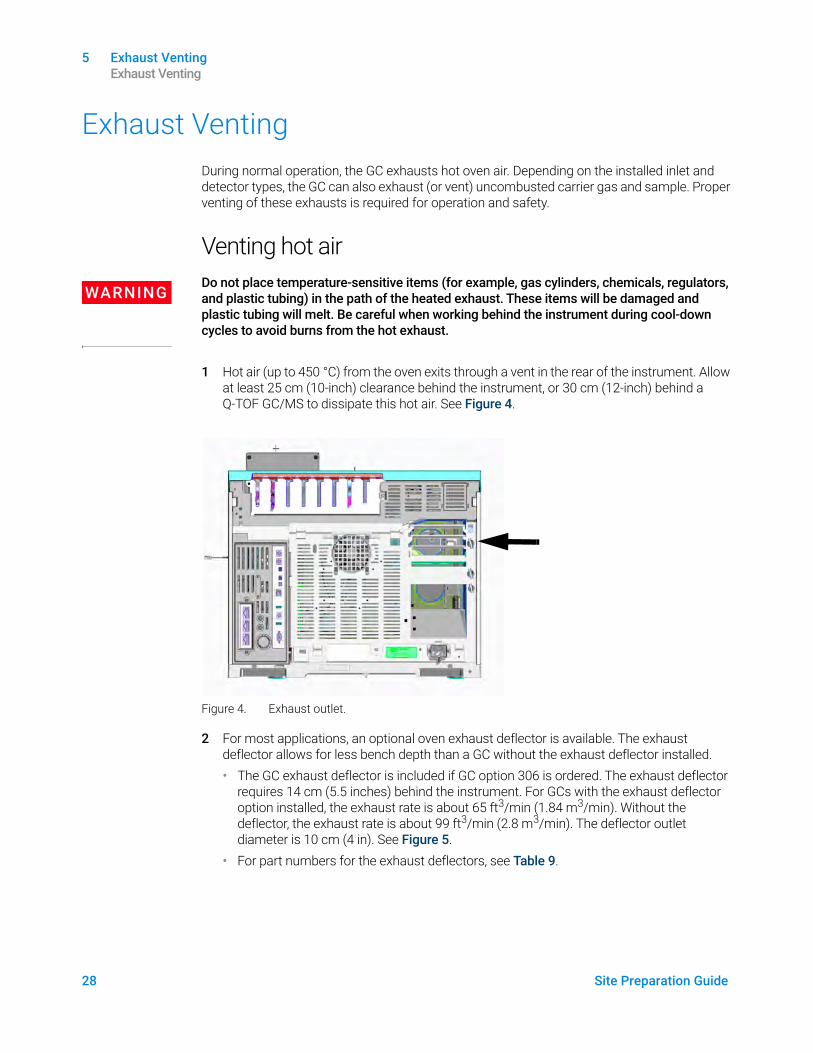
Exhaust VentingDuring normal operation, the GC exhausts hot oven air. Depending on the installed inlet and detector types, the GC can also exhaust (or vent) uncombusted carrier gas and sample. Proper venting of these exhausts is required for operation and safety.
Venting hot air
WARNINGDo not place temperature-sensitive items (for example, gas cylinders, chemicals, regulators, and plastic tubing) in the path of the heated exhaust. These items will be damaged and plastic tubing will melt. Be careful when working behind the instrument during cool-down cycles to avoid burns from the hot exhaust.
1 Hot air (up to 450 °C) from the oven exits through a vent in the rear of the instrument. Allow at least 25 cm (10-inch) clearance behind the instrument, or 30 cm (12-inch) behind a Q-TOF GC/MS to dissipate this hot air. See Figure 4.
Figure 4. Exhaust outlet.
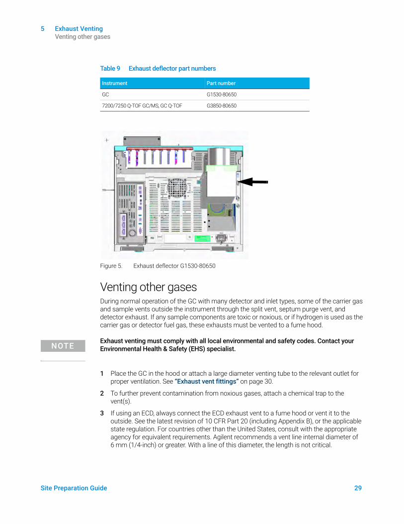
2 For most applications, an optional oven exhaust deflector is available. The exhaust deflector allows for less bench depth than a GC without the exhaust deflector installed.• The GC exhaust deflector is included if GC option 306 is ordered. The exhaust deflector
requires 14 cm (5.5 inches) behind the instrument. For GCs with the exhaust deflector option installed, the exhaust rate is about 65 ft3/min (1.84 m3/min). Without the deflector, the exhaust rate is about 99 ft3/min (2.8 m3/min). The deflector outlet diameter is 10 cm (4 in). See Figure 5.
• For part numbers for the exhaust deflectors, see Table 9.
5 Exhaust Venting Venting other gases
Site Preparation Guide 29
Figure 5. Exhaust deflector G1530-80650
Venting other gasesDuring normal operation of the GC with many detector and inlet types, some of the carrier gas and sample vents outside the instrument through the split vent, septum purge vent, and detector exhaust. If any sample components are toxic or noxious, or if hydrogen is used as the carrier gas or detector fuel gas, these exhausts must be vented to a fume hood.
NOTEExhaust venting must comply with all local environmental and safety codes. Contact your Environmental Health & Safety (EHS) specialist.
1 Place the GC in the hood or attach a large diameter venting tube to the relevant outlet for proper ventilation. See “Exhaust vent fittings” on page 30.
2 To further prevent contamination from noxious gases, attach a chemical trap to the vent(s).
3 If using an ECD, always connect the ECD exhaust vent to a fume hood or vent it to the outside. See the latest revision of 10 CFR Part 20 (including Appendix B), or the applicable state regulation. For countries other than the United States, consult with the appropriate agency for equivalent requirements. Agilent recommends a vent line internal diameter of 6 mm (1/4-inch) or greater. With a line of this diameter, the length is not critical.
Table 9 Exhaust deflector part numbers
Instrument Part number
GC G1530-80650
7200/7250 Q-TOF GC/MS, GC Q-TOF G3850-80650
5 Exhaust Venting Exhaust vent fittings
30 Site Preparation Guide
4 Vent the GC/MS system externally to the building via an ambient-pressure vent system, within 460 cm (15 ft) of both the GC split vent and GC/MS foreline pump, or vent to a fume hood.
Exhaust vent fittingsThe various inlet and detector vents terminate in the following fittings:
• TCD, ECD: The detector exhaust terminates in a 1/8-inch od tube.
• SSL, MMI, PTV, VI: The split vent terminates in a 1/8-inch Swagelok female fitting.
• All inlets: The septum purge vent terminates in 1/8-inch od tubing.
Site Preparation Guide 31
6 GC System Power RequirementsPower Requirements 32
USA fast heating oven, 240 V 34Canadian installation 34Common instrument power cord plugs 34
ALS Power Requirements 38
This section details the power requirements for GC, GC/MS, and automatic liquid sampler (ALS) installation.
6 GC System Power Requirements Power Requirements
32 Site Preparation Guide
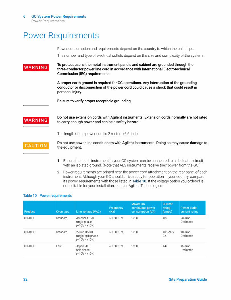
Power RequirementsPower consumption and requirements depend on the country to which the unit ships.
The number and type of electrical outlets depend on the size and complexity of the system.
WARNINGTo protect users, the metal instrument panels and cabinet are grounded through the three-conductor power line cord in accordance with International Electrotechnical Commission (IEC) requirements.
A proper earth ground is required for GC operations. Any interruption of the grounding conductor or disconnection of the power cord could cause a shock that could result in personal injury.
Be sure to verify proper receptacle grounding.
WARNINGDo not use extension cords with Agilent instruments. Extension cords normally are not rated to carry enough power and can be a safety hazard.
The length of the power cord is 2 meters (6.6 feet).
CAUTIONDo not use power line conditioners with Agilent instruments. Doing so may cause damage to the equipment.
1 Ensure that each instrument in your GC system can be connected to a dedicated circuit with an isolated ground. (Note that ALS instruments receive their power from the GC.)
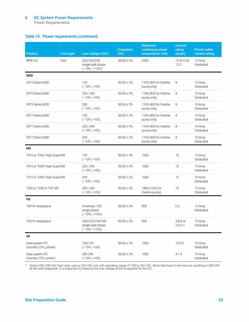
2 Power requirements are printed near the power cord attachment on the rear panel of each instrument. Although your GC should arrive ready for operation in your country, compare its power requirements with those listed in Table 10. If the voltage option you ordered is not suitable for your installation, contact Agilent Technologies.
Table 10 Power requirements
Product
Oven type
Line voltage (VAC)
Frequency (Hz)
Maximum continuous power consumption (VA)
Current rating (amps)
Power outlet current rating
8890 GC Standard Americas: 120 single phase (–10% / +10%)
50/60 ± 5% 2250 18.8 20 Amp Dedicated
8890 GC Standard 220/230/240 single/split phase (–10% / +10%)
50/60 ± 5% 2250 10.2/9.8/ 9.4
10 Amp Dedicated
8890 GC Fast Japan 200 split phase (–10% / +10%)
50/60 ± 5% 2950 14.8 15 Amp Dedicated
6 GC System Power Requirements Power Requirements
Site Preparation Guide 33
8890 GC Fast 220/230/240 single/split phase (–10% / +10%)*
50/60 ± 5% 2950 13.4/12.8/ 12.3
15 Amp Dedicated
MSD
5975 Series MSD 120 (–10% / +5%)
50/60 ± 5% 1100 (400 for foreline pump only)
8 10 Amp Dedicated
5975 Series MSD 220–240 (–10% / +5%)
50/60 ± 5% 1100 (400 for foreline pump only)
8 10 Amp Dedicated
5975 Series MSD 200 (–10% / +5%)
50/60 ± 5% 1100 (400 for foreline pump only)
8 10 Amp Dedicated
5977 Series MSD 120 (–10% / +5%)
50/60 ± 5% 1100 (400 for foreline pump only)
8 10 Amp Dedicated
5977 Series MSD 220–240 (–10% / +5%)
50/60 ± 5% 1100 (400 for foreline pump only)
8 10 Amp Dedicated
5977 Series MSD 200 (–10% / +5%)
50/60 ± 5% 1100 (400 for foreline pump only)
8 10 Amp Dedicated
MS
7010 or 7000 Triple Quad MS 120 (–10% / +5%)
50/60 ± 5% 1600 15 15 Amp Dedicated
7010 or 7000 Triple Quad MS 220–240 (–10% / +5%)
50/60 ± 5% 1600 15 15 Amp Dedicated
7010 or 7000 Triple Quad MS 200 (–10% / +5%)
50/60 ± 5% 1600 15 15 Amp Dedicated
7200 or 7250 Q-TOF MS 200–240 (–10% / +5%)
50/60 ± 5% 1800 (1200 for foreline pump)
15 15 Amp Dedicated
HS
7697A Headspace Americas: 120 single phase (–10% / +10%)
50/60 ± 5% 850 6.2 15 Amp Dedicated
7697A Headspace 200/220/230/240 single/split phase (–10% / +10%)
50/60 ± 5% 850 3.8/3.4/ 3.3/3.1
10 Amp Dedicated
All
Data system PC (monitor, CPU, printer)
100/120 (–10% / +5%)
50/60 ± 5% 1000 10/8.3 15 Amp Dedicated
Data system PC (monitor, CPU, printer)
200-240 (–10% / +5%)
50/60 ± 5% 1000 4.1-5 10 Amp Dedicated
* Option 003, 208 VAC fast oven, uses a 220 VAC unit with operating range of 198 to 242 VAC. Most labs have 4-wire service resulting in 208 VAC at the wall receptacle. It is important to measure the line voltage at the receptacle for the GC.
Table 10 Power requirements (continued)
Product
Oven type
Line voltage (VAC)
Frequency (Hz)
Maximum continuous power consumption (VA)
Current rating (amps)
Power outlet current rating
6 GC System Power Requirements USA fast heating oven, 240 V
34 Site Preparation Guide
NOTEThe GC and related equipment meet the following International Electrotechnical Commission (IEC) classifications: Equipment Class I, Laboratory Equipment, Installation Category II, and Pollution Degree 2.
USA fast heating oven, 240 VThe 240 V fast heating oven requires 240 V/15 A power. Do not use 208 V power. Lower voltage causes slow oven ramps and prevents proper temperature control. The power cord supplied with your GC is rated for 250 V/15 A, and is a two-pole, three-wire cord with grounding (type L6-15R/L6-15P).
Canadian installationWhen installing a GC in Canada, make sure your GC power supply circuit meets the following additional requirements:
• The circuit breaker for the branch circuit, which is dedicated to the instrument, is rated for continuous operation.
• The service box branch circuit is marked as a “Dedicated Circuit.”
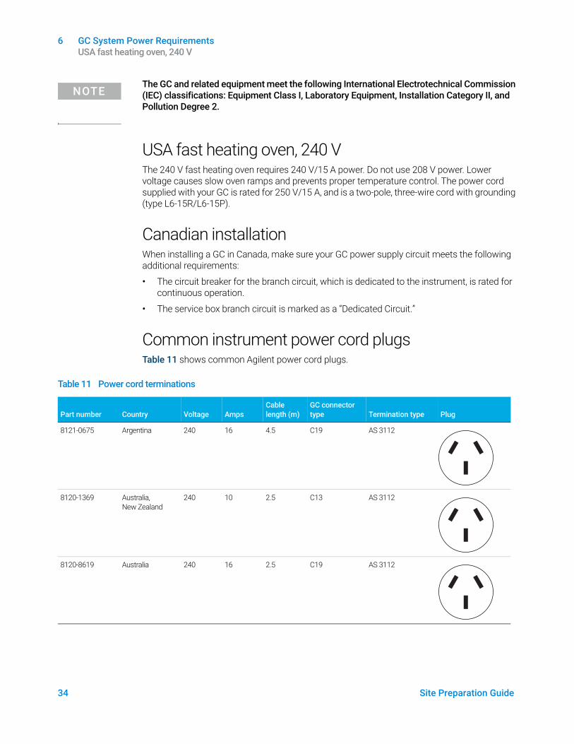
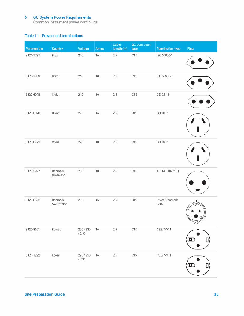
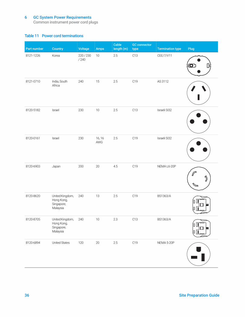
Common instrument power cord plugsTable 11 shows common Agilent power cord plugs.
Table 11 Power cord terminations
Part number
Country
Voltage
Amps
Cable length (m)
GC connector type
Termination type
Plug
8121-0675 Argentina 240 16 4.5 C19 AS 3112
8120-1369 Australia, New Zealand
240 10 2.5 C13 AS 3112
8120-8619 Australia 240 16 2.5 C19 AS 3112
6 GC System Power Requirements Common instrument power cord plugs
Site Preparation Guide 35
8121-1787 Brazil 240 16 2.5 C19 IEC 60906-1
8121-1809 Brazil 240 10 2.5 C13 IEC 60906-1
8120-6978 Chile 240 10 2.5 C13 CEI 23-16
8121-0070 China 220 16 2.5 C19 GB 1002
8121-0723 China 220 10 2.5 C13 GB 1002
8120-3997 Denmark, Greenland
230 10 2.5 C13 AFSNIT 107-2-01
8120-8622 Denmark, Switzerland
230 16 2.5 C19 Swiss/Denmark 1302
8120-8621 Europe 220 / 230 / 240
16 2.5 C19 CEE/7/V11
8121-1222 Korea 220 / 230 / 240
16 2.5 C19 CEE/7/V11
Table 11 Power cord terminations
Part number
Country
Voltage
Amps
Cable length (m)
GC connector type
Termination type
Plug
6 GC System Power Requirements Common instrument power cord plugs
36 Site Preparation Guide
8121-1226 Korea 220 / 230 / 240
10 2.5 C13 CEE/7/V11
8121-0710 India, South Africa
240 15 2.5 C19 AS 3112
8120-5182 Israel 230 10 2.5 C13 Israeli SI32
8120-0161 Israel 230 16, 16 AWG
2.5 C19 Israeli SI32
8120-6903 Japan 200 20 4.5 C19 NEMA L6-20P
8120-8620 United Kingdom, Hong Kong, Singapore, Malaysia
240 13 2.5 C19 BS1363/A
8120-8705 United Kingdom, Hong Kong, Singapore, Malaysia
240 10 2.3 C13 BS1363/A
8120-6894 United States 120 20 2.5 C19 NEMA 5-20P
Table 11 Power cord terminations
Part number
Country
Voltage
Amps
Cable length (m)
GC connector type
Termination type
Plug
6 GC System Power Requirements Common instrument power cord plugs
Site Preparation Guide 37
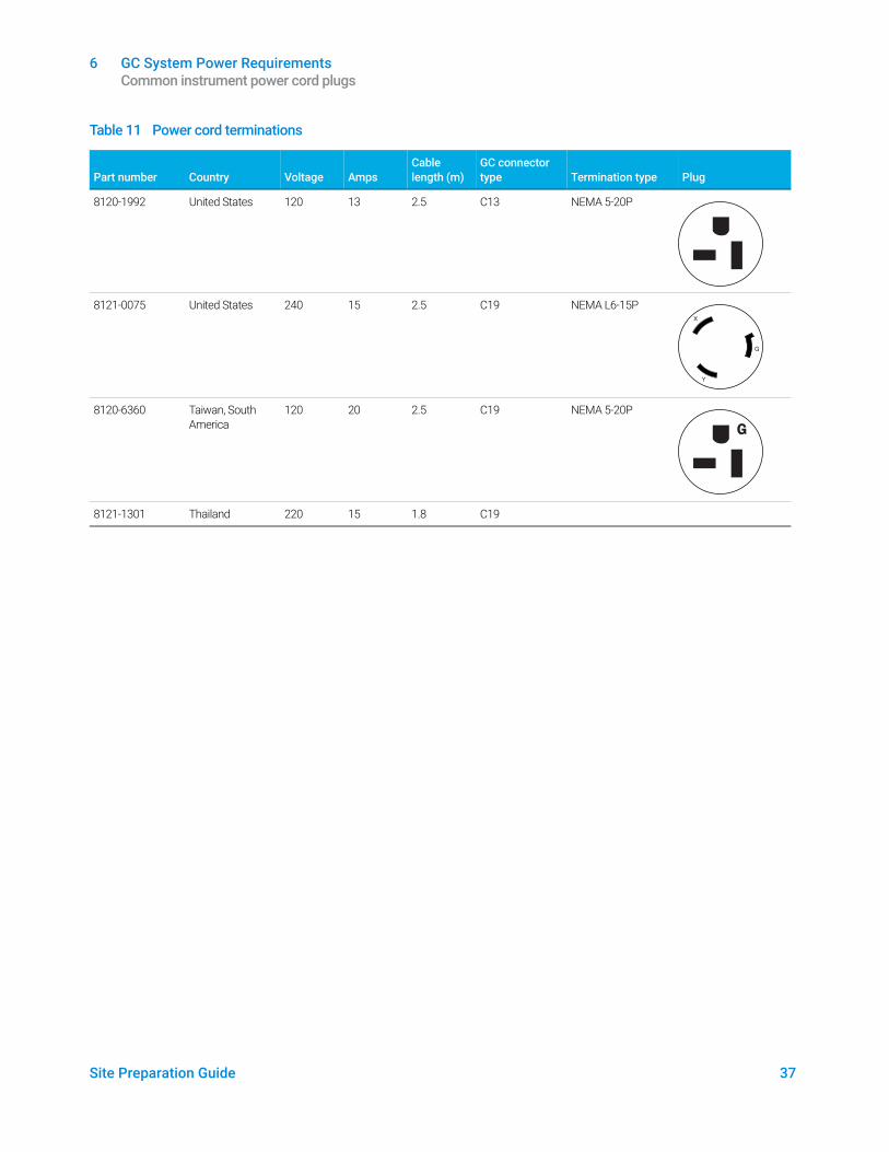
8120-1992 United States 120 13 2.5 C13 NEMA 5-20P
8121-0075 United States 240 15 2.5 C19 NEMA L6-15P
8120-6360 Taiwan, South America
120 20 2.5 C19 NEMA 5-20P
8121-1301 Thailand 220 15 1.8 C19
Table 11 Power cord terminations
Part number
Country
Voltage
Amps
Cable length (m)
GC connector type
Termination type
Plug
G
6 GC System Power Requirements ALS Power Requirements
38 Site Preparation Guide
ALS Power RequirementsThe ALS components draw power from the GC. No other power source is required.
The G4517A controller, used with the 8890 series GC, requires one electrical outlet with a dedicated ground. The controller can be set for either 100-120 V or 200-240 V.
WARNINGDo not use extension cords with Agilent instruments. Extension cords normally are not rated to carry enough power and can be a safety hazard.
The length of the power cord is 2 meters (6.6 feet).
Site Preparation Guide 39
7 Gas Selection and PlumbingGas and Reagent Selection 40
Hydrogen Carrier Gas 42Gas and Reagent Purity 42Gas Supplies 43GC/MS Gas Requirements 45
Gas Plumbing 49Supply tubing for most carrier and detector gases 50Supply tubing for hydrogen gas 50Two-stage pressure regulators 51Pressure regulator-gas supply tubing connections 51Filters and traps 52
This section outlines the requirements for gas selection and plumbing.
Refer to the Agilent Web site at www.agilent.com for the most up-to-date listing of GC, GC/MS, and ALS supplies and consumables.
7 Gas Selection and Plumbing Gas and Reagent Selection
40 Site Preparation Guide
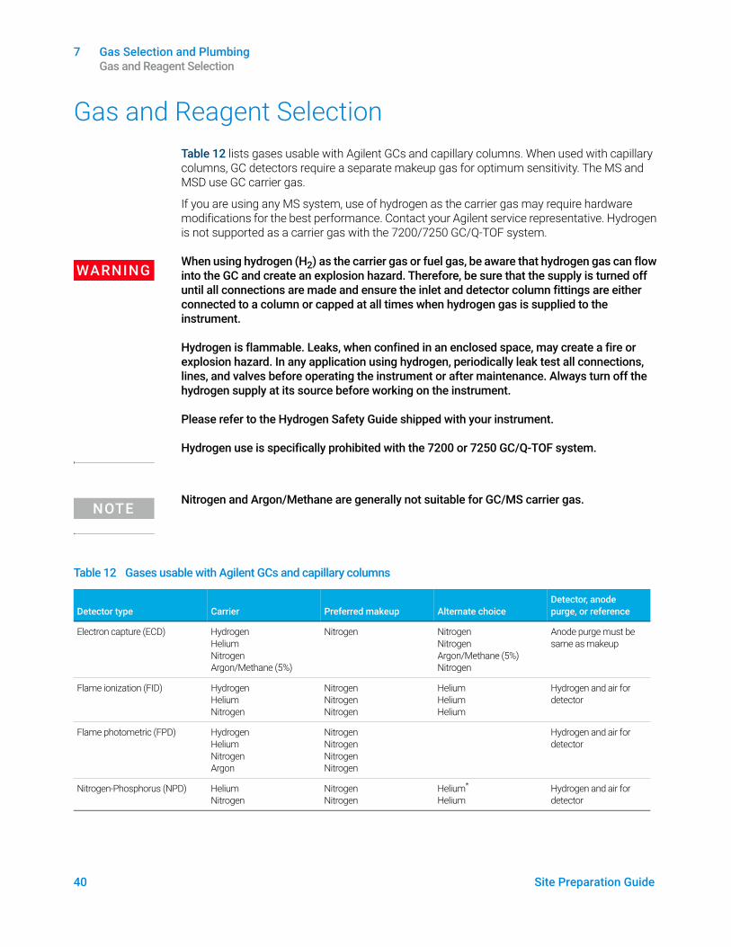
Gas and Reagent SelectionTable 12 lists gases usable with Agilent GCs and capillary columns. When used with capillary columns, GC detectors require a separate makeup gas for optimum sensitivity. The MS and MSD use GC carrier gas.
If you are using any MS system, use of hydrogen as the carrier gas may require hardware modifications for the best performance. Contact your Agilent service representative. Hydrogen is not supported as a carrier gas with the 7200/7250 GC/Q-TOF system.
WARNINGWhen using hydrogen (H2) as the carrier gas or fuel gas, be aware that hydrogen gas can flow into the GC and create an explosion hazard. Therefore, be sure that the supply is turned off until all connections are made and ensure the inlet and detector column fittings are either connected to a column or capped at all times when hydrogen gas is supplied to the instrument.
Hydrogen is flammable. Leaks, when confined in an enclosed space, may create a fire or explosion hazard. In any application using hydrogen, periodically leak test all connections, lines, and valves before operating the instrument or after maintenance. Always turn off the hydrogen supply at its source before working on the instrument.
Please refer to the Hydrogen Safety Guide shipped with your instrument.
Hydrogen use is specifically prohibited with the 7200 or 7250 GC/Q-TOF system.
NOTENitrogen and Argon/Methane are generally not suitable for GC/MS carrier gas.
Table 12 Gases usable with Agilent GCs and capillary columns
Detector type
Carrier
Preferred makeup
Alternate choice
Detector, anode purge, or reference
Electron capture (ECD) Hydrogen Helium Nitrogen Argon/Methane (5%)
Nitrogen Nitrogen Nitrogen Argon/Methane (5%) Nitrogen
Anode purge must be same as makeup
Flame ionization (FID) Hydrogen Helium Nitrogen
Nitrogen Nitrogen Nitrogen
Helium Helium Helium
Hydrogen and air for detector
Flame photometric (FPD) Hydrogen Helium Nitrogen Argon
Nitrogen Nitrogen Nitrogen Nitrogen
Hydrogen and air for detector
Nitrogen-Phosphorus (NPD) Helium Nitrogen
Nitrogen Nitrogen
Helium* Helium
Hydrogen and air for detector
7 Gas Selection and Plumbing Gas and Reagent Selection
Site Preparation Guide 41
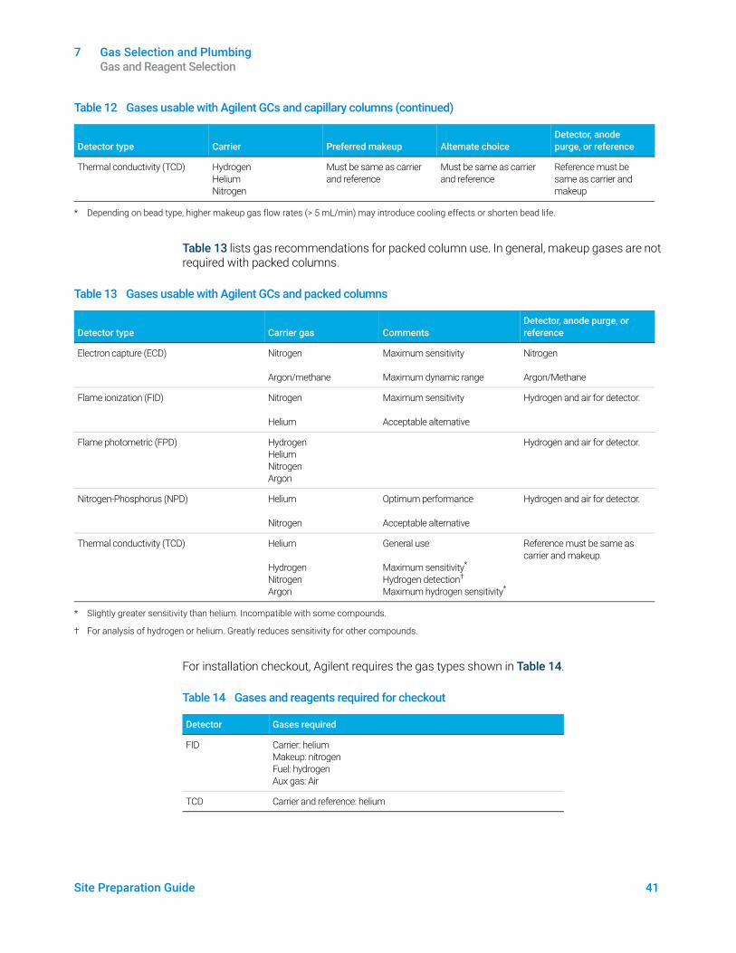
Table 13 lists gas recommendations for packed column use. In general, makeup gases are not required with packed columns.
For installation checkout, Agilent requires the gas types shown in Table 14.
Thermal conductivity (TCD) Hydrogen Helium Nitrogen
Must be same as carrier and reference
Must be same as carrier and reference
Reference must be same as carrier and makeup
* Depending on bead type, higher makeup gas flow rates (> 5 mL/min) may introduce cooling effects or shorten bead life.
Table 12 Gases usable with Agilent GCs and capillary columns (continued)
Detector type
Carrier
Preferred makeup
Alternate choice
Detector, anode purge, or reference
Table 13 Gases usable with Agilent GCs and packed columns
Detector type
Carrier gas
Comments
Detector, anode purge, or reference
Electron capture (ECD) Nitrogen
Argon/methane
Maximum sensitivity
Maximum dynamic range
Nitrogen
Argon/Methane
Flame ionization (FID) Nitrogen
Helium
Maximum sensitivity
Acceptable alternative
Hydrogen and air for detector.
Flame photometric (FPD) HydrogenHeliumNitrogenArgon
Hydrogen and air for detector.
Nitrogen-Phosphorus (NPD) Helium
Nitrogen
Optimum performance
Acceptable alternative
Hydrogen and air for detector.
Thermal conductivity (TCD) Helium
HydrogenNitrogenArgon
General use
Maximum sensitivity*
Hydrogen detection†
Maximum hydrogen sensitivity*
Reference must be same as carrier and makeup.
* Slightly greater sensitivity than helium. Incompatible with some compounds.
† For analysis of hydrogen or helium. Greatly reduces sensitivity for other compounds.
Table 14 Gases and reagents required for checkout
Detector Gases required
FID Carrier: heliumMakeup: nitrogenFuel: hydrogenAux gas: Air
TCD Carrier and reference: helium
7 Gas Selection and Plumbing Hydrogen Carrier Gas
42 Site Preparation Guide
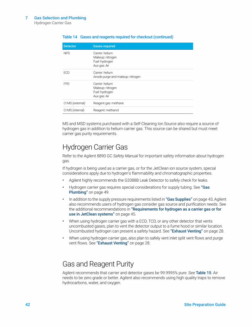
MS and MSD systems purchased with a Self-Cleaning Ion Source also require a source of hydrogen gas in addition to helium carrier gas. This source can be shared but must meet carrier gas purity requirements.
Hydrogen Carrier GasRefer to the Agilent 8890 GC Safety Manual for important safety information about hydrogen gas.
If hydrogen is being used as a carrier gas, or for the JetClean ion source system, special considerations apply due to hydrogen’s flammability and chromatographic properties.
• Agilent highly recommends the G3388B Leak Detector to safely check for leaks.
• Hydrogen carrier gas requires special considerations for supply tubing. See “Gas Plumbing” on page 49.
• In addition to the supply pressure requirements listed in “Gas Supplies” on page 43, Agilent also recommends users of hydrogen gas consider gas source and purification needs. See the additional recommendations in “Requirements for hydrogen as a carrier gas or for use in JetClean systems” on page 45.
• When using hydrogen carrier gas with a ECD, TCD, or any other detector that vents uncombusted gases, plan to vent the detector output to a fume hood or similar location. Uncombusted hydrogen can present a safety hazard. See “Exhaust Venting” on page 28.
• When using hydrogen carrier gas, also plan to safely vent inlet split vent flows and purge vent flows. See “Exhaust Venting” on page 28.
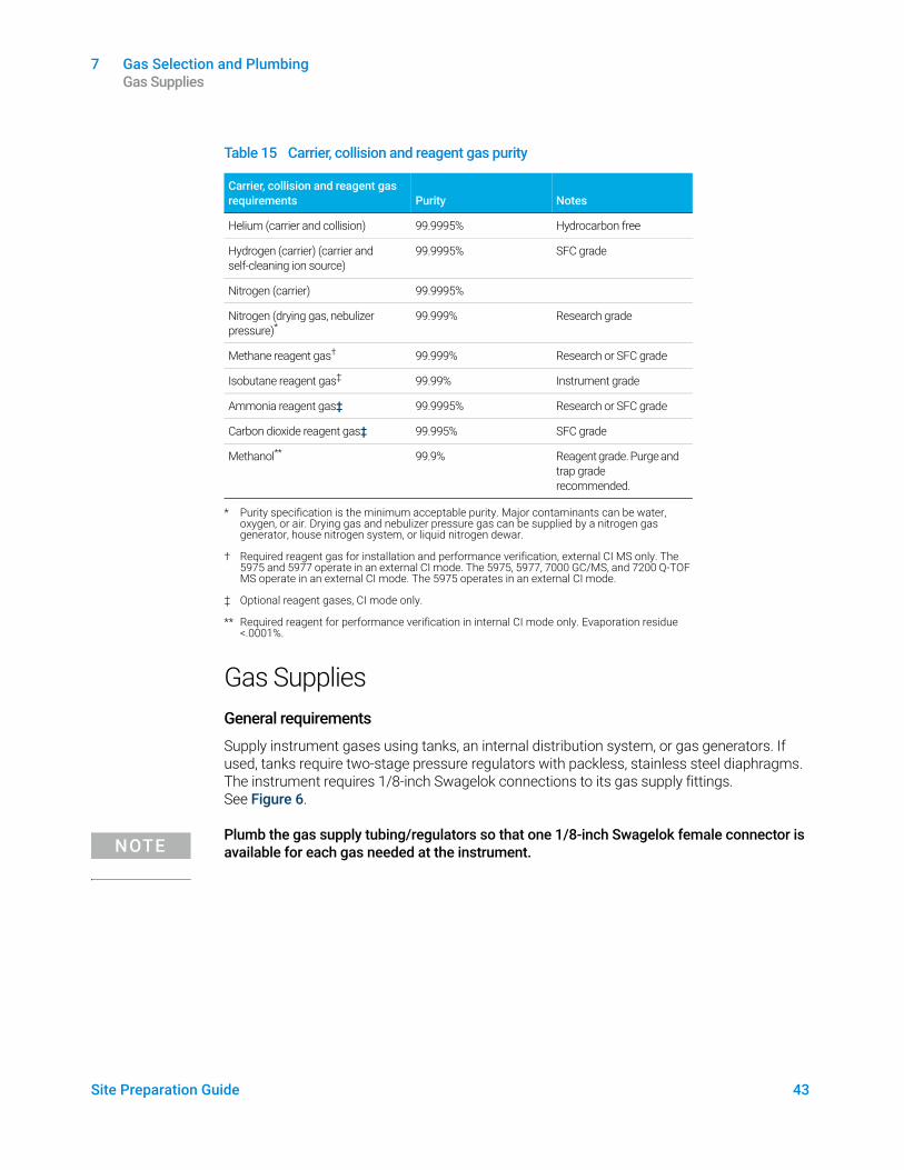
Gas and Reagent PurityAgilent recommends that carrier and detector gases be 99.9995% pure. See Table 15. Air needs to be zero grade or better. Agilent also recommends using high quality traps to remove hydrocarbons, water, and oxygen.
NPD Carrier: heliumMakeup: nitrogenFuel: hydrogenAux gas: Air
ECD Carrier: heliumAnode purge and makeup: nitrogen
FPD Carrier: heliumMakeup: nitrogenFuel: hydrogenAux gas: Air
CI MS (external) Reagent gas: methane
CI MS (internal) Reagent: methanol
Table 14 Gases and reagents required for checkout (continued)
Detector Gases required
7 Gas Selection and Plumbing Gas Supplies
Site Preparation Guide 43
Gas SuppliesGeneral requirements
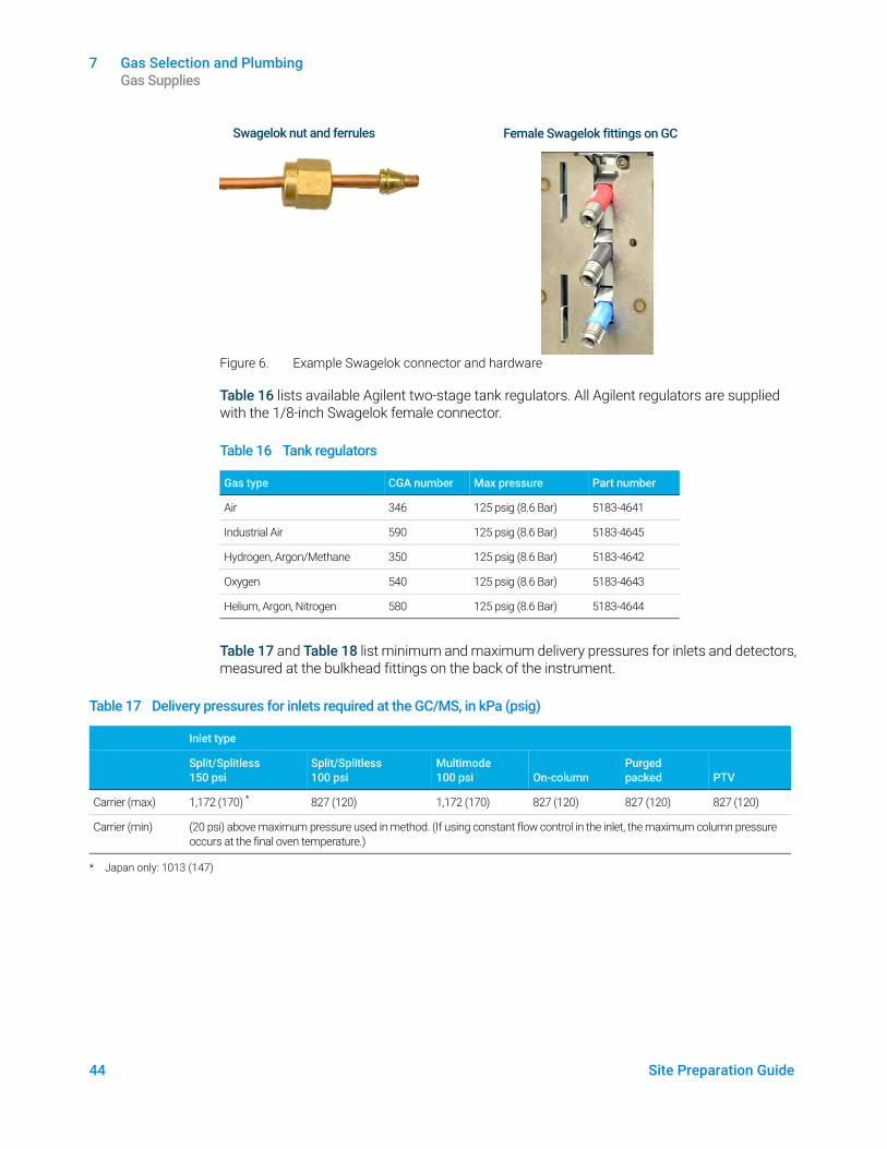
Supply instrument gases using tanks, an internal distribution system, or gas generators. If used, tanks require two-stage pressure regulators with packless, stainless steel diaphragms. The instrument requires 1/8-inch Swagelok connections to its gas supply fittings. See Figure 6.
NOTEPlumb the gas supply tubing/regulators so that one 1/8-inch Swagelok female connector is available for each gas needed at the instrument.
Table 15 Carrier, collision and reagent gas purity
Carrier, collision and reagent gas requirements
Purity
Notes
Helium (carrier and collision) 99.9995% Hydrocarbon free
Hydrogen (carrier) (carrier and self-cleaning ion source)
99.9995% SFC grade
Nitrogen (carrier) 99.9995%
Nitrogen (drying gas, nebulizer pressure)*
* Purity specification is the minimum acceptable purity. Major contaminants can be water, oxygen, or air. Drying gas and nebulizer pressure gas can be supplied by a nitrogen gas generator, house nitrogen system, or liquid nitrogen dewar.
99.999% Research grade
Methane reagent gas†
† Required reagent gas for installation and performance verification, external CI MS only. The 5975 and 5977 operate in an external CI mode. The 5975, 5977, 7000 GC/MS, and 7200 Q-TOF MS operate in an external CI mode. The 5975 operates in an external CI mode.
99.999% Research or SFC grade
Isobutane reagent gas‡
‡ Optional reagent gases, CI mode only.
99.99% Instrument grade
Ammonia reagent gas‡ 99.9995% Research or SFC grade
Carbon dioxide reagent gas‡ 99.995% SFC grade
Methanol**
** Required reagent for performance verification in internal CI mode only. Evaporation residue <.0001%.
99.9% Reagent grade. Purge and trap grade recommended.
7 Gas Selection and Plumbing Gas Supplies
44 Site Preparation Guide
Figure 6. Example Swagelok connector and hardware
Table 16 lists available Agilent two-stage tank regulators. All Agilent regulators are supplied with the 1/8-inch Swagelok female connector.
Table 17 and Table 18 list minimum and maximum delivery pressures for inlets and detectors, measured at the bulkhead fittings on the back of the instrument.
Table 16 Tank regulators
Gas type CGA number Max pressure Part number
Air 346 125 psig (8.6 Bar) 5183-4641
Industrial Air 590 125 psig (8.6 Bar) 5183-4645
Hydrogen, Argon/Methane 350 125 psig (8.6 Bar) 5183-4642
Oxygen 540 125 psig (8.6 Bar) 5183-4643
Helium, Argon, Nitrogen 580 125 psig (8.6 Bar) 5183-4644
Swagelok nut and ferrules Female Swagelok fittings on GC
Table 17 Delivery pressures for inlets required at the GC/MS, in kPa (psig)
Inlet type
Split/Splitless 150 psi
Split/Splitless 100 psi
Multimode 100 psi
On-column
Purged packed
PTV
Carrier (max) 1,172 (170) * 827 (120) 1,172 (170) 827 (120) 827 (120) 827 (120)
Carrier (min) (20 psi) above maximum pressure used in method. (If using constant flow control in the inlet, the maximum column pressure occurs at the final oven temperature.)
* Japan only: 1013 (147)
7 Gas Selection and Plumbing GC/MS Gas Requirements
Site Preparation Guide 45
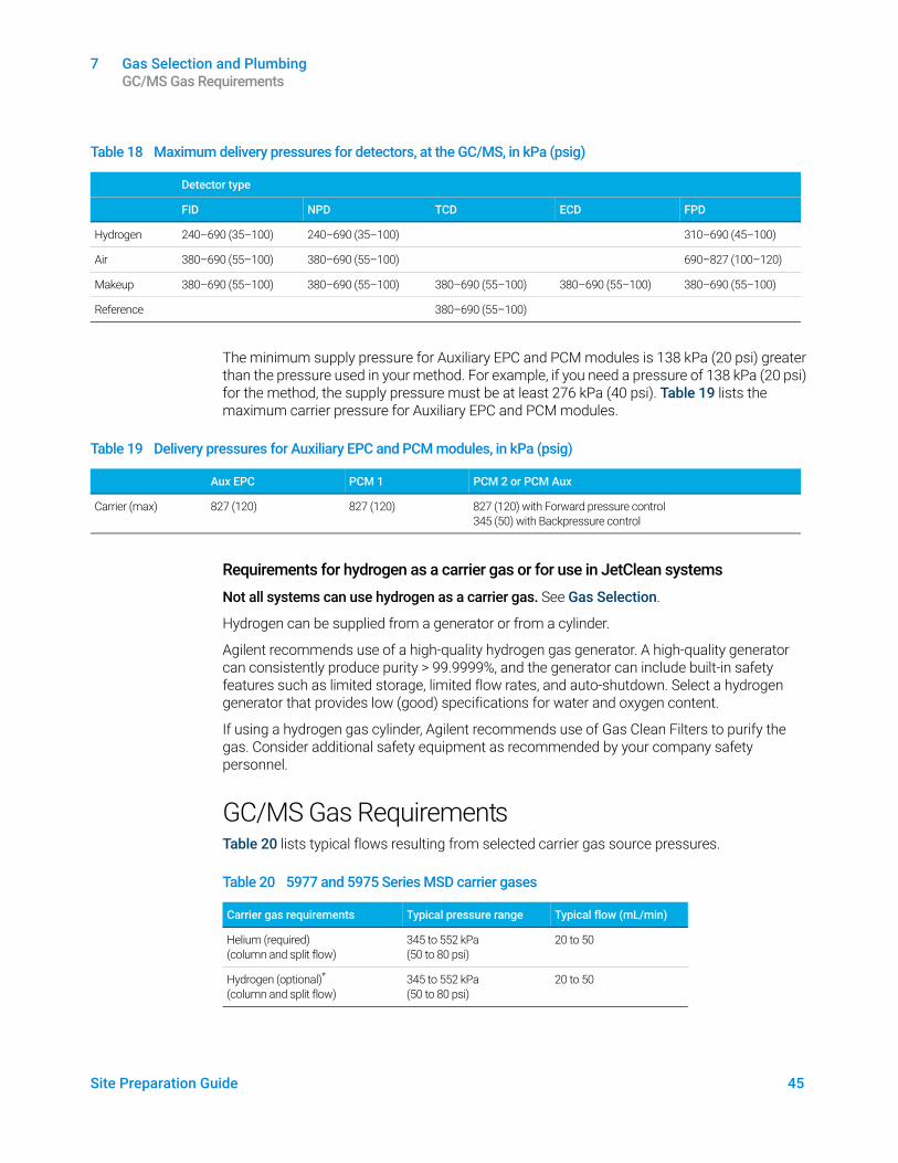
The minimum supply pressure for Auxiliary EPC and PCM modules is 138 kPa (20 psi) greater than the pressure used in your method. For example, if you need a pressure of 138 kPa (20 psi) for the method, the supply pressure must be at least 276 kPa (40 psi). Table 19 lists the maximum carrier pressure for Auxiliary EPC and PCM modules.
Requirements for hydrogen as a carrier gas or for use in JetClean systems
Not all systems can use hydrogen as a carrier gas. See Gas Selection.
Hydrogen can be supplied from a generator or from a cylinder.
Agilent recommends use of a high-quality hydrogen gas generator. A high-quality generator can consistently produce purity > 99.9999%, and the generator can include built-in safety features such as limited storage, limited flow rates, and auto-shutdown. Select a hydrogen generator that provides low (good) specifications for water and oxygen content.
If using a hydrogen gas cylinder, Agilent recommends use of Gas Clean Filters to purify the gas. Consider additional safety equipment as recommended by your company safety personnel.
GC/MS Gas RequirementsTable 20 lists typical flows resulting from selected carrier gas source pressures.
Table 18 Maximum delivery pressures for detectors, at the GC/MS, in kPa (psig)
Detector type
FID NPD TCD ECD FPD
Hydrogen 240–690 (35–100) 240–690 (35–100) 310–690 (45–100)
Air 380–690 (55–100) 380–690 (55–100) 690–827 (100–120)
Makeup 380–690 (55–100) 380–690 (55–100) 380–690 (55–100) 380–690 (55–100) 380–690 (55–100)
Reference 380–690 (55–100)
Table 19 Delivery pressures for Auxiliary EPC and PCM modules, in kPa (psig)
Aux EPC PCM 1 PCM 2 or PCM Aux
Carrier (max) 827 (120) 827 (120) 827 (120) with Forward pressure control345 (50) with Backpressure control
Table 20 5977 and 5975 Series MSD carrier gases
Carrier gas requirements Typical pressure range Typical flow (mL/min)
Helium (required) (column and split flow)
345 to 552 kPa (50 to 80 psi)
20 to 50
Hydrogen (optional)* (column and split flow)
345 to 552 kPa (50 to 80 psi)
20 to 50
7 Gas Selection and Plumbing GC/MS Gas Requirements
46 Site Preparation Guide
7010 and 7000 Series MS
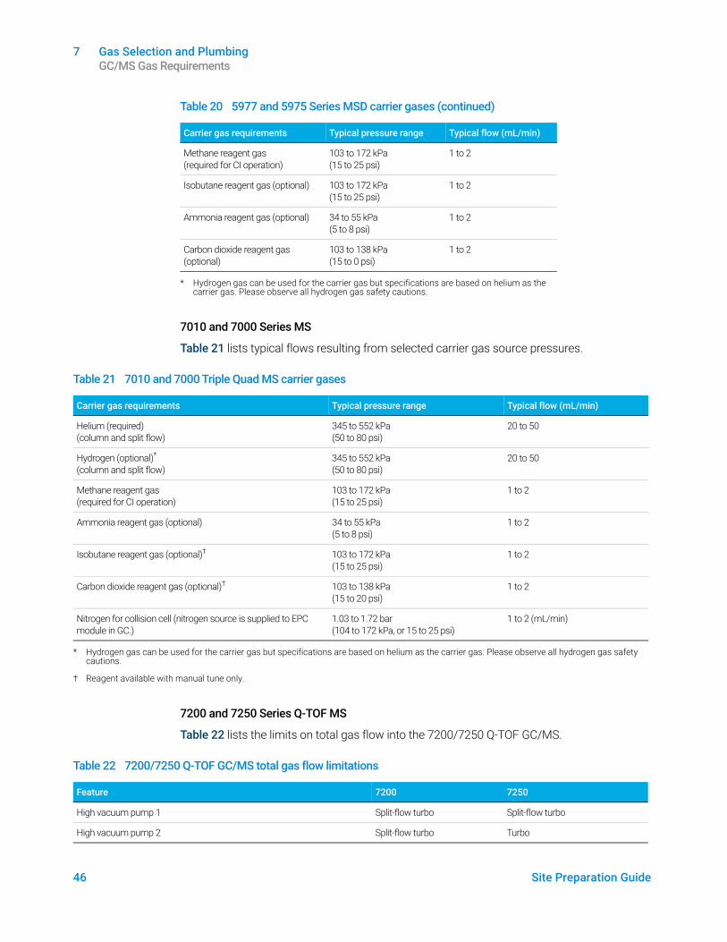
Table 21 lists typical flows resulting from selected carrier gas source pressures.
7200 and 7250 Series Q-TOF MS
Table 22 lists the limits on total gas flow into the 7200/7250 Q-TOF GC/MS.
Methane reagent gas (required for CI operation)
103 to 172 kPa (15 to 25 psi)
1 to 2
Isobutane reagent gas (optional) 103 to 172 kPa (15 to 25 psi)
1 to 2
Ammonia reagent gas (optional) 34 to 55 kPa (5 to 8 psi)
1 to 2
Carbon dioxide reagent gas (optional)
103 to 138 kPa (15 to 0 psi)
1 to 2
* Hydrogen gas can be used for the carrier gas but specifications are based on helium as the carrier gas. Please observe all hydrogen gas safety cautions.
Table 20 5977 and 5975 Series MSD carrier gases (continued)
Carrier gas requirements Typical pressure range Typical flow (mL/min)
Table 21 7010 and 7000 Triple Quad MS carrier gases
Carrier gas requirements Typical pressure range Typical flow (mL/min)
Helium (required) (column and split flow)
345 to 552 kPa (50 to 80 psi)
20 to 50
Hydrogen (optional)* (column and split flow)
345 to 552 kPa (50 to 80 psi)
20 to 50
Methane reagent gas (required for CI operation)
103 to 172 kPa (15 to 25 psi)
1 to 2
Ammonia reagent gas (optional) 34 to 55 kPa (5 to 8 psi)
1 to 2
Isobutane reagent gas (optional)† 103 to 172 kPa (15 to 25 psi)
1 to 2
Carbon dioxide reagent gas (optional)† 103 to 138 kPa (15 to 20 psi)
1 to 2
Nitrogen for collision cell (nitrogen source is supplied to EPC module in GC.)
1.03 to 1.72 bar (104 to 172 kPa, or 15 to 25 psi)
1 to 2 (mL/min)
* Hydrogen gas can be used for the carrier gas but specifications are based on helium as the carrier gas. Please observe all hydrogen gas safety cautions.
† Reagent available with manual tune only.
Table 22 7200/7250 Q-TOF GC/MS total gas flow limitations
Feature 7200 7250
High vacuum pump 1 Split-flow turbo Split-flow turbo
High vacuum pump 2 Split-flow turbo Turbo
7 Gas Selection and Plumbing GC/MS Gas Requirements
Site Preparation Guide 47
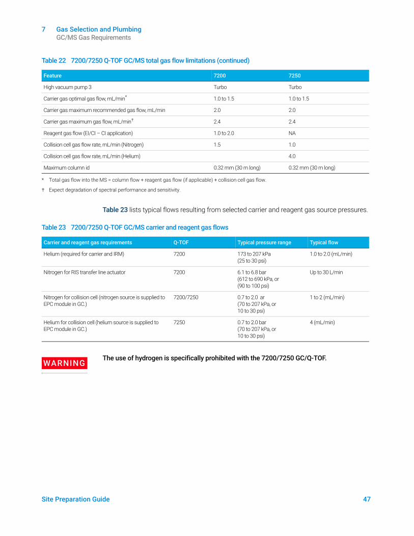
Table 23 lists typical flows resulting from selected carrier and reagent gas source pressures.
WARNINGThe use of hydrogen is specifically prohibited with the 7200/7250 GC/Q-TOF.
High vacuum pump 3 Turbo Turbo
Carrier gas optimal gas flow, mL/min* 1.0 to 1.5 1.0 to 1.5
Carrier gas maximum recommended gas flow, mL/min 2.0 2.0
Carrier gas maximum gas flow, mL/min† 2.4 2.4
Reagent gas flow (EI/CI – CI application) 1.0 to 2.0 NA
Collision cell gas flow rate, mL/min (Nitrogen) 1.5 1.0
Collision cell gas flow rate, mL/min (Helium) 4.0
Maximum column id 0.32 mm (30 m long) 0.32 mm (30 m long)
* Total gas flow into the MS = column flow + reagent gas flow (if applicable) + collision cell gas flow.
† Expect degradation of spectral performance and sensitivity.
Table 22 7200/7250 Q-TOF GC/MS total gas flow limitations (continued)
Feature 7200 7250
Table 23 7200/7250 Q-TOF GC/MS carrier and reagent gas flows
Carrier and reagent gas requirements Q-TOF Typical pressure range Typical flow
Helium (required for carrier and IRM) 7200 173 to 207 kPa (25 to 30 psi)
1.0 to 2.0 (mL/min)
Nitrogen for RIS transfer line actuator 7200 6.1 to 6.8 bar (612 to 690 kPa, or (90 to 100 psi)
Up to 30 L/min
Nitrogen for collision cell (nitrogen source is supplied to EPC module in GC.)
7200/7250 0.7 to 2.0 ar (70 to 207 kPa, or 10 to 30 psi)
1 to 2 (mL/min)
Helium for collision cell (helium source is supplied to EPC module in GC.)
7250 0.7 to 2.0 bar (70 to 207 kPa, or 10 to 30 psi)
4 (mL/min)
7 Gas Selection and Plumbing Performance verification
48 Site Preparation Guide
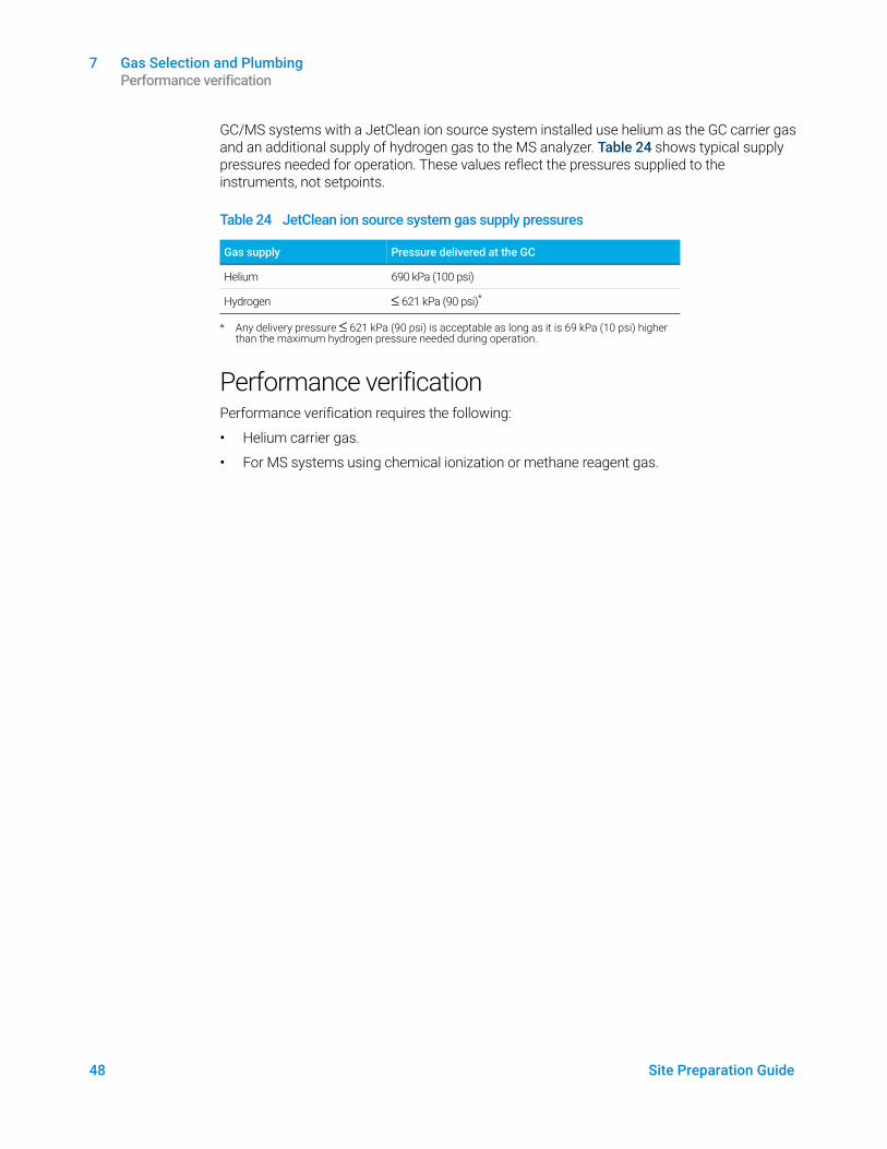
GC/MS systems with a JetClean ion source system installed use helium as the GC carrier gas and an additional supply of hydrogen gas to the MS analyzer. Table 24 shows typical supply pressures needed for operation. These values reflect the pressures supplied to the instruments, not setpoints.
Performance verificationPerformance verification requires the following:
• Helium carrier gas.
• For MS systems using chemical ionization or methane reagent gas.
Table 24 JetClean ion source system gas supply pressures
Gas supply Pressure delivered at the GC
Helium 690 kPa (100 psi)
Hydrogen ≤ 621 kPa (90 psi)*
* Any delivery pressure ≤ 621 kPa (90 psi) is acceptable as long as it is 69 kPa (10 psi) higher than the maximum hydrogen pressure needed during operation.
7 Gas Selection and Plumbing Gas Plumbing
Site Preparation Guide 49
Gas Plumbing
WARNINGAll compressed gas cylinders should be securely fastened to an immovable structure or permanent wall. Compressed gases should be stored and handled in accordance with the relevant safety codes.
Gas cylinders should not be located in the path of heated oven exhaust.
To avoid possible eye injury, wear eye protection when using compressed gas.
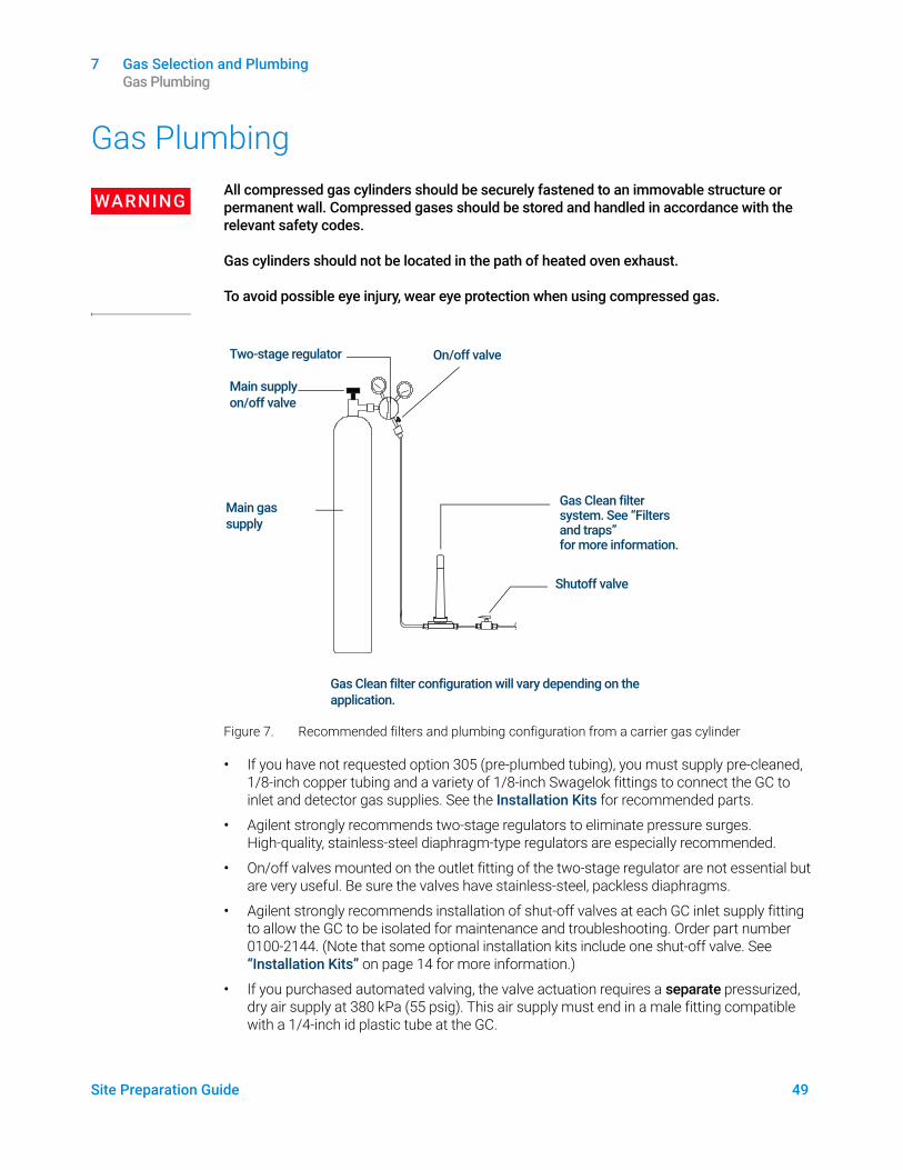
Figure 7. Recommended filters and plumbing configuration from a carrier gas cylinder
• If you have not requested option 305 (pre-plumbed tubing), you must supply pre-cleaned, 1/8-inch copper tubing and a variety of 1/8-inch Swagelok fittings to connect the GC to inlet and detector gas supplies. See the Installation Kits for recommended parts.
• Agilent strongly recommends two-stage regulators to eliminate pressure surges. High-quality, stainless-steel diaphragm-type regulators are especially recommended.
• On/off valves mounted on the outlet fitting of the two-stage regulator are not essential but are very useful. Be sure the valves have stainless-steel, packless diaphragms.
• Agilent strongly recommends installation of shut-off valves at each GC inlet supply fitting to allow the GC to be isolated for maintenance and troubleshooting. Order part number 0100-2144. (Note that some optional installation kits include one shut-off valve. See “Installation Kits” on page 14 for more information.)
• If you purchased automated valving, the valve actuation requires a separate pressurized, dry air supply at 380 kPa (55 psig). This air supply must end in a male fitting compatible with a 1/4-inch id plastic tube at the GC.
Two-stage regulator
Main supply on/off valve
Main gas supply
On/off valve
Gas Clean filter system. See “Filters and traps” on page 52 for more information.
Shutoff valve
Gas Clean filter configuration will vary depending on the application.
7 Gas Selection and Plumbing Supply tubing for most carrier and detector gases
50 Site Preparation Guide
• FID, FPD, and NPD detectors require a dedicated air supply. Operation may be affected by pressure pulses in air lines shared with other devices.
• Flow- and pressure-controlling devices require at least 10 psi (138 kPa) pressure differential across them to operate properly. Set source pressures and capacities high enough to ensure this.
• Situate auxiliary pressure regulators close to the GC inlet fittings. This ensures that the supply pressure is measured at the instrument (rather than at the source); pressure at the source may be different if the gas supply lines are long or narrow.
• Never use liquid thread sealer to connect fittings.
• Never use chlorinated solvents to clean tubing or fittings.
See “Installation Kits” on page 14 for more information.
Supply tubing for most carrier and detector gasesUse only preconditioned copper tubing (part number 5180-4196) to supply gases to the instrument. Do not use ordinary copper tubing—it contains oils and contaminants.
CAUTIONDo not use methylene chloride or other halogenated solvent to clean tubing that will be used with an electron capture detector. They will cause elevated baselines and detector noise until they are completely flushed out of the system.
CAUTIONDo not use plastic tubing for suppling detector and inlet gases to the GC. It is permeable to oxygen and other contaminants that can damage columns and detectors.
Plastic tubing can melt if near hot exhaust or components.
The tubing diameter depends on the distance between the supply gas and the GC and the total flow rate for the particular gas. Tubing of 1/8-in diameter is adequate when the supply line is less than 15 feet (4.6 m) long.
Use larger diameter tubing (1/4-inch) for distances greater then 15 feet (4.6 m) or when multiple instruments are connected to the same source. Use larger diameter tubing if high demand is anticipated (for example, air for an FID).
Be generous when cutting tubing for local supply lines—a coil of flexible tubing between the supply and the instrument lets you move the GC without moving the gas supply. Take this extra length into account when choosing the tubing diameter.
Supply tubing for hydrogen gasAgilent recommends using new chromatographic quality stainless steel tubing and fittings when using hydrogen.
• Do not re-use old tubing when installing or switching to hydrogen supply lines for carrier gas or the JetClean ion source system. Hydrogen gas tends to remove contaminants left on old tubing by previous gases (by helium, for example). These contaminants can appear in output as high background noise or hydrocarbon contamination for several weeks.
• Especially do not use old copper tubing, which can become brittle.
7 Gas Selection and Plumbing Two-stage pressure regulators
Site Preparation Guide 51
WARNINGDo not use old copper tubing with hydrogen gas. Old copper tubing can become brittle and create a safety hazard.
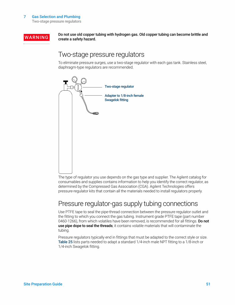
Two-stage pressure regulatorsTo eliminate pressure surges, use a two-stage regulator with each gas tank. Stainless steel, diaphragm-type regulators are recommended.
The type of regulator you use depends on the gas type and supplier. The Agilent catalog for consumables and supplies contains information to help you identify the correct regulator, as determined by the Compressed Gas Association (CGA). Agilent Technologies offers pressure-regulator kits that contain all the materials needed to install regulators properly.
Pressure regulator-gas supply tubing connectionsUse PTFE tape to seal the pipe-thread connection between the pressure regulator outlet and the fitting to which you connect the gas tubing. Instrument grade PTFE tape (part number 0460-1266), from which volatiles have been removed, is recommended for all fittings. Do not use pipe dope to seal the threads; it contains volatile materials that will contaminate the tubing.
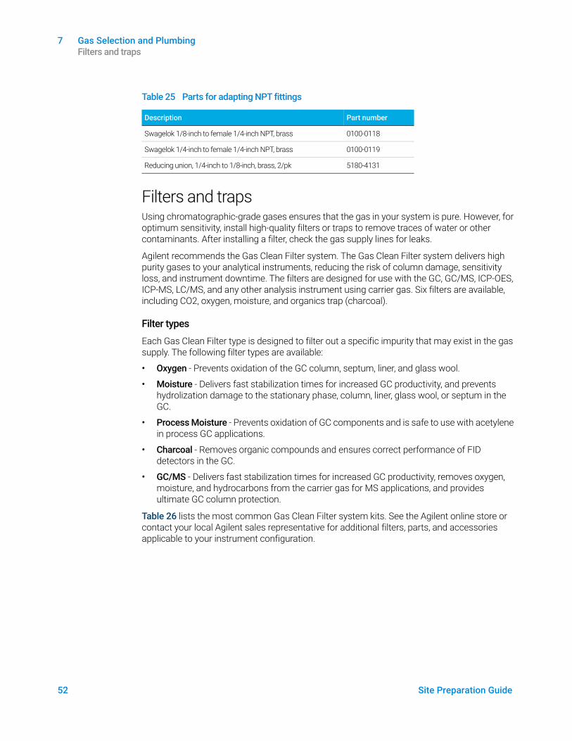
Pressure regulators typically end in fittings that must be adapted to the correct style or size. Table 25 lists parts needed to adapt a standard 1/4-inch male NPT fitting to a 1/8-inch or 1/4-inch Swagelok fitting.
Two-stage regulator
Adapter to 1/8-inch female Swagelok fitting
7 Gas Selection and Plumbing Filters and traps
52 Site Preparation Guide
Filters and trapsUsing chromatographic-grade gases ensures that the gas in your system is pure. However, for optimum sensitivity, install high-quality filters or traps to remove traces of water or other contaminants. After installing a filter, check the gas supply lines for leaks.
Agilent recommends the Gas Clean Filter system. The Gas Clean Filter system delivers high purity gases to your analytical instruments, reducing the risk of column damage, sensitivity loss, and instrument downtime. The filters are designed for use with the GC, GC/MS, ICP-OES, ICP-MS, LC/MS, and any other analysis instrument using carrier gas. Six filters are available, including CO2, oxygen, moisture, and organics trap (charcoal).
Filter types
Each Gas Clean Filter type is designed to filter out a specific impurity that may exist in the gas supply. The following filter types are available:
• Oxygen - Prevents oxidation of the GC column, septum, liner, and glass wool.
• Moisture - Delivers fast stabilization times for increased GC productivity, and prevents hydrolization damage to the stationary phase, column, liner, glass wool, or septum in the GC.
• Process Moisture - Prevents oxidation of GC components and is safe to use with acetylene in process GC applications.
• Charcoal - Removes organic compounds and ensures correct performance of FID detectors in the GC.
• GC/MS - Delivers fast stabilization times for increased GC productivity, removes oxygen, moisture, and hydrocarbons from the carrier gas for MS applications, and provides ultimate GC column protection.
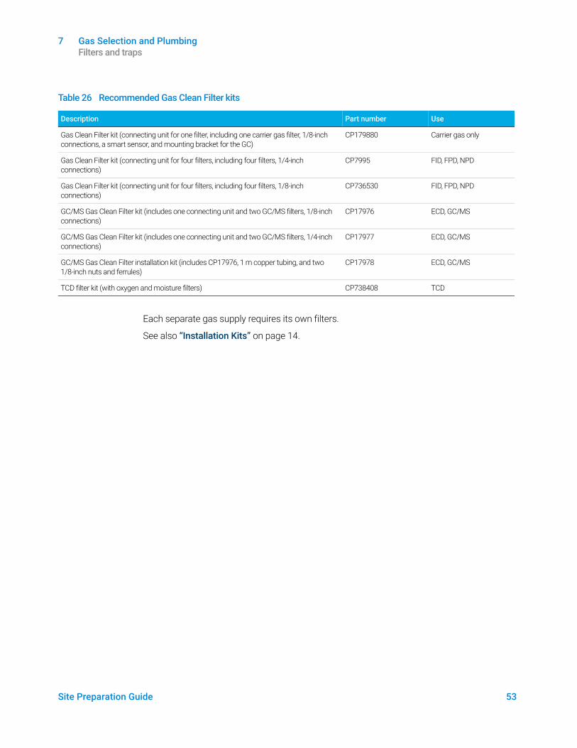
Table 26 lists the most common Gas Clean Filter system kits. See the Agilent online store or contact your local Agilent sales representative for additional filters, parts, and accessories applicable to your instrument configuration.
Table 25 Parts for adapting NPT fittings
Description Part number
Swagelok 1/8-inch to female 1/4-inch NPT, brass 0100-0118
Swagelok 1/4-inch to female 1/4-inch NPT, brass 0100-0119
Reducing union, 1/4-inch to 1/8-inch, brass, 2/pk 5180-4131
7 Gas Selection and Plumbing Filters and traps
Site Preparation Guide 53
Each separate gas supply requires its own filters.
See also “Installation Kits” on page 14.
Table 26 Recommended Gas Clean Filter kits
Description Part number Use
Gas Clean Filter kit (connecting unit for one filter, including one carrier gas filter, 1/8-inch connections, a smart sensor, and mounting bracket for the GC)
CP179880 Carrier gas only
Gas Clean Filter kit (connecting unit for four filters, including four filters, 1/4-inch connections)
CP7995 FID, FPD, NPD
Gas Clean Filter kit (connecting unit for four filters, including four filters, 1/8-inch connections)
CP736530 FID, FPD, NPD
GC/MS Gas Clean Filter kit (includes one connecting unit and two GC/MS filters, 1/8-inch connections)
CP17976 ECD, GC/MS
GC/MS Gas Clean Filter kit (includes one connecting unit and two GC/MS filters, 1/4-inch connections)
CP17977 ECD, GC/MS
GC/MS Gas Clean Filter installation kit (includes CP17976, 1 m copper tubing, and two 1/8-inch nuts and ferrules)
CP17978 ECD, GC/MS
TCD filter kit (with oxygen and moisture filters) CP738408 TCD

7 Gas Selection and Plumbing Filters and traps
54 Site Preparation Guide
Site Preparation Guide 55
8 Cryogenic Cooling RequirementsCryogenic Cooling Requirements 56
Using carbon dioxide 56Using liquid nitrogen 57Using compressed air 58
This section outlines the site requirements for cryogenic cooling for the GC inlets and oven.
Refer to the Agilent Web site at www.agilent.com for the most up-to-date listing of GC, GC/MS, and ALS supplies and consumables.
8 Cryogenic Cooling Requirements Cryogenic Cooling Requirements
56 Site Preparation Guide
Cryogenic Cooling RequirementsCryogenic cooling allows you to cool the oven or inlet, including cooling to setpoints below ambient temperature. A solenoid valve controls the flow of coolant to the inlet or oven. The oven can use either liquid carbon dioxide (CO2) or liquid nitrogen (N2) as a coolant. All inlets except the multimode inlet must use the same coolant type as the oven. (The multimode inlet can use a different coolant than configured for the oven, and can also use compressed air as a coolant.)
CO2 and N2 coolants require different hardware on the GC. (You can use air cooling on a multimode inlet, with either the CO2 or N2 solenoid valves and hardware.)
Oven cryogenic cooling is not compatible with the 7000 Triple Quad MS or 7200/7250 Q-TOF MS. If your application requires GC oven cryogenic cooling, contact your Agilent sales representative.
Using carbon dioxide
WARNINGPressurized liquid CO2 is a hazardous material. Take precautions to protect personnel from high pressures and low temperatures. CO2 in high concentrations is toxic to humans; take precautions to prevent hazardous concentrations. Consult your local supplier for recommended safety precautions and delivery system design.
CAUTIONLiquid CO2 should not be used as a coolant for oven temperatures below –40 °C because the expanding liquid may form solid CO2—dry ice—in the GC oven. If dry ice builds up in the oven, it can seriously damage the GC.
Liquid CO2 is available in high-pressure tanks containing liquid. Typical liquid CO2 tank pressure will be 4830 to 6900 kPa (700 to 1,000 psi) at a temperature of 25 °C. The CO2 should be free of particulate material, oil, and other contaminants. These contaminants could clog the expansion orifice or affect the proper operation of the GC.
WARNINGDo not use copper tubing or thin-wall stainless steel tubing with liquid CO2. Both harden at stress points and may explode.
Additional requirements for the liquid CO2 system include:
• The tank must have an internal dip tube or eductor tube to deliver liquid CO2 instead of gas (see the figure below).
• Use 1/8-inch diameter heavy-wall stainless steel tubing for supply tubing. The tubing should be between 1.5 and 15 m (5 and 50 feet) long. (Agilent part number 7157-0210, 20 ft)
• Coil and fasten the ends of the tubing to prevent it from “whipping” if it breaks.
8 Cryogenic Cooling Requirements Using liquid nitrogen
Site Preparation Guide 57
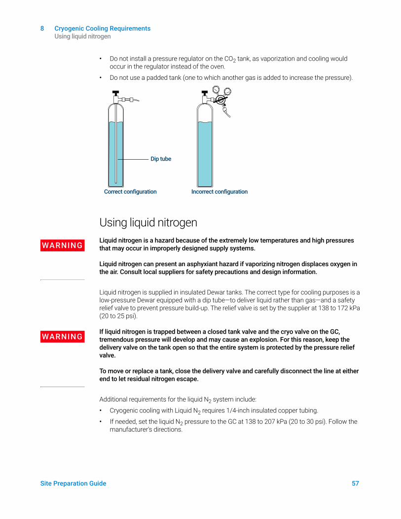
• Do not install a pressure regulator on the CO2 tank, as vaporization and cooling would occur in the regulator instead of the oven.
• Do not use a padded tank (one to which another gas is added to increase the pressure).
Using liquid nitrogen
WARNINGLiquid nitrogen is a hazard because of the extremely low temperatures and high pressures that may occur in improperly designed supply systems.
Liquid nitrogen can present an asphyxiant hazard if vaporizing nitrogen displaces oxygen in the air. Consult local suppliers for safety precautions and design information.
Liquid nitrogen is supplied in insulated Dewar tanks. The correct type for cooling purposes is a low-pressure Dewar equipped with a dip tube—to deliver liquid rather than gas—and a safety relief valve to prevent pressure build-up. The relief valve is set by the supplier at 138 to 172 kPa (20 to 25 psi).
WARNINGIf liquid nitrogen is trapped between a closed tank valve and the cryo valve on the GC, tremendous pressure will develop and may cause an explosion. For this reason, keep the delivery valve on the tank open so that the entire system is protected by the pressure relief valve.
To move or replace a tank, close the delivery valve and carefully disconnect the line at either end to let residual nitrogen escape.
Additional requirements for the liquid N2 system include:
• Cryogenic cooling with Liquid N2 requires 1/4-inch insulated copper tubing.
• If needed, set the liquid N2 pressure to the GC at 138 to 207 kPa (20 to 30 psi). Follow the manufacturer's directions.
Dip tube
Correct configuration Incorrect configuration
8 Cryogenic Cooling Requirements Using compressed air
58 Site Preparation Guide
• Make sure the supply tubing for liquid N2 is insulated. Foam tubing used for refrigeration and air-conditioning lines is suitable for insulation. (Foam tubing insulation is not supplied by Agilent. Contact a local supplier.) Since pressures are low, insulated copper tubing is adequate.
• Situate the liquid nitrogen tank close (within 1.5 to 3 m, or 5 to 10 feet) to the GC to ensure that liquid, not gas, is supplied to the inlet.
Using compressed airThe multimode inlet can also use compressed air cooling with the liquid N2 inlet cooling option. Requirements for compressed air cooling:
• The compressed air should be free of particulate material, oil, and other contaminants. These contaminants could clog the inlet's cryo valve and expansion orifice or impact the proper operation of the GC.
• The required air supply pressure depends on the installed solenoid valve type. For a multimode inlet with N2 cooling, set the air supply pressure to 138 to 208 kPa (20 and 30 psig).
While air supplied from tanks can meet these criteria, the consumption rate of air can be 80 L/min, varying based on supply pressure.
Installation of a compressed air line to the inlet cryo coolant valve requires 1/4-inch copper or stainless steel tubing for supply tubing to the N2 valve.
Site Preparation Guide 59
A LAN RequirementsSite LAN Network 60
This section outlines the site LAN requirements for GC, GC/MS, and automatic liquid sampler (ALS) installation.
A LAN Requirements Site LAN Network
60 Site Preparation Guide
Site LAN Network
NOTEAgilent Technologies is not responsible for connecting to or establishing communication with your site LAN network. The Agilent representative will test the system’s ability to communicate on a mini-hub or LAN switch only.
If you intend to connect your system to your site’s LAN network, you must have an additional shielded twisted pair network cable (8121-0940).
NOTEThe IP addresses assigned to the instrument(s) must be fixed (permanently assigned) addresses. If you intend to connect your system to your site’s network, each piece of equipment must have a unique, fixed (static) IP address assigned to it.
NOTEFor a Single Quad GC/MS system, Agilent recommends, sells, and supports the use of a PC with one (1) network interface card (NIC) and a network switch to isolate the GC/MS system from the site LAN. The network switch supplied with Agilent systems prevents instrument-to-PC network traffic from entering the site LAN and keeps site LAN network traffic from interfering with instrument-to-PC communications. Agilent develops and tests all Single Quad GC/MS hardware and software using the single NIC configuration and has no known network configuration issues. Alternate network configurations can be configured and managed by the end user at their own risk and expense.
NOTEFor Triple Quad and 7200 Q-TOF GC/MS systems, Agilent recommends, sells, and supports the use of a PC with two network interface cards (NIC) to provide both a site LAN connection and an isolated GC/MS system connection. Agilent develops and tests all Triple Quad and Q-TOF GC/MS hardware and software using the dual NIC configuration, and has no known network configuration issues. Alternate network configurations can be configured and managed by the end user at their own risk and expense.
NOTEFor the 7250 Q-TOF GC/MS systems, Agilent recommends, sells, and supports the use of a PC with three network interface cards (NIC) to provide a site LAN connection, MS only connection, and an isolated GC/MS system connection. Agilent develops and tests Q-TOF GC/MS hardware and software using the triple NIC configuration, and has no known network configuration issues. Alternate network configurations can be configured and managed by the end user at their own risk and expense.

61 Site Preparation Guide
This page intentionally left blank.