
Site Planning for AVANCE Systems 750-950 MHz -...
126
Version Site Planning for AVANCE Systems 750-950 MHz User Guide 002
Transcript of Site Planning for AVANCE Systems 750-950 MHz -...

Site Planning forAVANCE Systems
750-950 MHzUser Guide
Version
002
The information in this manual may be altered without notice.
BRUKER BIOSPIN accepts no responsibility for actions takenas a result of use of this manual. BRUKER BIOSPIN acceptsno liability for any mistakes contained in the manual, leading tocoincidental damage, whether during installation or operation ofthe instrument. Unauthorized reproduction of manual contents,without written permission from the publishers, or translationinto another language, either in full or in part, is forbidden.
This manual was written by
Razvan Theodorescu
This manual was desktop published by
Stanley J. Niles
© August 11, 2006: Bruker Biospin GmbH
Rheinstetten, Germany
P/N: Z31686DWG-Nr.: 1393002
Contents
Contents ............................................................... 3
1 Introduction ........................................................... 71.1 Introduction ......................................................................... 7
How to Use This Manual ..................................................8Units Used Within This Manual ........................................8
1.2 Warnings and Notes .......................................................... 101.3 Contact for Additional Technical Assistance ....................... 10
2 Safety ....................................................................112.1 Introduction ....................................................................... 112.2 The Magnetic Field ............................................................ 11
Exclusion Zone .............................................................. 11Security Zone ................................................................12Standards on Health and Safety in the Workplace ..........12
2.3 Ventilation ......................................................................... 13Regular Ventilation ........................................................13Emergency Ventilation ...................................................13Oxygen Sensors ............................................................14
2.4 Safe Handling of Cryogenic Substances ............................ 14Refill of Liquid Nitrogen ..................................................14Refill of Liquid Helium ....................................................14
2.5 Earthquake Safety ............................................................. 162.6 Country-specific Safety Regulations .................................. 16
3 Equipment ............................................................ 173.1 Introduction ....................................................................... 173.2 Superconducting Magnet Components ............................... 173.3 Console, Monitoring & Control Unit .................................... 183.4 CryoProbe System (Optional) ............................................ 21
4 Magnet Access and Rigging ................................ 234.1 Introduction ....................................................................... 234.2 Off-loading on Site ............................................................. 244.3 Access to the NMR Room .................................................. 254.4 Magnet Transport Weights ................................................. 264.5 Rigging Equipment ............................................................ 27
5 Ceiling Height Requirements .............................. 295.1 Introduction ....................................................................... 29
User Guide Version 002 BRUKER BIOSPIN 3

Contents
6 Magnetic Stray Fields ...........................................336.1 Introduction ....................................................................... 33
7 Floor Plan .............................................................437.1 Size and Mass of Equipment ............................................. 437.2 Magnet Location ............................................................... 457.3 Magnet Slab ...................................................................... 467.4 Magnet Platform ................................................................ 477.5 Sample Changer Considerations ....................................... 487.6 Magnet Pump Line ............................................................ 487.7 Magnet Pits ....................................................................... 497.8 Maximum Field Strengths for NMR Equipment ................... 507.9 Worktable Position ............................................................ 517.10 Layout Examples .............................................................. 51
8 Environment and Site Survey Measurement .......578.1 Introduction ....................................................................... 578.2 Vibrations .......................................................................... 57
Vibration Guidelines ...................................................... 58Vibration Damping Measures ......................................... 58
8.3 Magnetic Environment ....................................................... 59Minimum Requirements ................................................. 59
Static Iron Distribution ........................................... 59Moveable Magnetic Material .................................. 59
Acceptable Environment ................................................ 60Static Objects ........................................................ 60 60Moving Objects ...................................................... 60
8.4 Electromagnetic Interference ............................................. 61Types of EMF Interference ..................................... 61
DC EMF Interference ..................................................... 61Measuring DC Fluctuating Fields ........................... 61Reducing DC Interference ..................................... 61Guidelines: DC Interference ................................... 62
50/60 Hz EMF Interference ............................................ 62Measuring 50/60 Hz Fluctuating Fields .................. 62Guidelines: 50/60 Hz Interference .......................... 63
RF Interference ............................................................. 63Measuring RF Fluctuating Fields ............................ 63Guidelines: RF Interference ................................... 63Reducing RF Interference ...................................... 63
9 Utility Requirements .............................................659.1 Electrical Power Requirements .......................................... 659.2 Telecommunication ........................................................... 669.3 Compressed Gas .............................................................. 67
General Requirements ........................................... 67Compressed Gas Options .............................................. 67
Option 1 (preferred): .............................................. 67Option 2: ............................................................... 67
4 BRUKER BIOSPIN User Guide Version 002

Contents
Option 3 (not recommended unless exclusive use of a CryoProbe is expected) ..........................................67Note: .....................................................................67
Gas Requirements For Accessories ...............................68Compressed Gas Specifications .....................................68
Oil Content: ...........................................................68Water Content ........................................................68Solid Impurities ......................................................68
Air Compressors ............................................................699.4 Water ................................................................................ 709.5 Lighting ............................................................................. 709.6 HVAC (Heating Ventilation Air Conditioning) ...................... 719.7 Fire Detection System and Fire Extinguishers .................... 729.8 Emergency Gas Exhaust ................................................... 729.9 Oxygen Monitor and Level Sensors ................................... 75
10 Installation ........................................................... 7710.1 Introduction ....................................................................... 7710.2 Overview ........................................................................... 7710.3 Accessibility ...................................................................... 7810.4 Checklist of Installation Requirements ............................... 7810.5 Installation Procedure ........................................................ 79
Magnet Assembly ..........................................................79Magnet Evacuation and Flushing with Nitrogen Gas .......79Cooling the Magnet to Liquid Nitrogen Temperatures .....79Cooling the Magnet to Liquid Helium Temperatures ........80Sub-cooling and Charging the Magnet ...........................80
Figures ................................................................ 83
Tables .................................................................. 85
Index ................................................................... 87
User Guide Version 002 BRUKER BIOSPIN 5

Contents
6 BRUKER BIOSPIN User Guide Version 002

1Introduction 1
Introduction 1.1
The fundamentally superior precision of fully digital signal generation and pro-cessing was introduced and established by the precedent-setting series of BrukerBioSpin AVANCETM NMR spectrometers. With its digital advantage, the AVAN-CETM series set revolutionary standards for performance, long-term reliability andease-of-use, whether for routine applications or the most demanding research.
The next-generation Avance II NMR spectrometer series features a second-gen-eration digital receiver technology (2G-DRTM), a new milestone in NMR detectionfidelity. The 2G-DR provides significant benefits for the most demanding NMR ap-plications, e.g., materials science, polymer analysis, trace analysis, LC-NMR, MRimaging and structural biology, particularly for measurements with ultrasensitiveCryoProbesTM.
Through its advanced modular design the AVANCE II can be optimally configuredfor any modern application: from classical analytical work to the most demandingstructural proteomics; from high-throughput screening to high-power solids NMRto microimaging. The AVANCE II can be delivered in a variety of configurations,ranging from a minimum-footprint microbay system up to a three cabinet instru-ment fully equipped for high power solids NMR with four or more channels.
Site planning requirements for Avance and AVANCE II are identical, so in thismanual they will be referred to as simply AVANCE systems.
Recommendations regarding site planning are based on the experience gainedby Bruker BioSpin engineers through the years. Every effort has been made tomake the site requirements realistic and readily achievable. It must be stressedhowever, that the figures quoted are only recommendations. Likewise, anyperformance values that are used are minimum values that should be readilyachievable by every system. Predicting NMR performance is complicated by thefact that every site is unique. This manual has been written to help you plan thesite, but it carries no guarantee of ultimate NMR performance.
While every effort has been made to ensure the information contained here-in is accurate, Bruker BioSpin accepts no liability for consequential loss ordamage arising from its use. Specifications are subject to change withoutnotice and where a value (e.g., ceiling height) lies close to a recommendedminimum value you are advised to check with Bruker BioSpin before finaldelivery
User Guide Version 002 BRUKER BIOSPIN 7 (93)

Introduction
How to Use This Manual 1.1.1
This manual contains information about site planning and preparation prior to de-livery of a Bruker BioSpin AVANCE system. After reading this manual you shouldhave enough information to make an initial decision as to whether a proposed siteis suitable for locating an AVANCE spectrometer and magnet. The manual shouldbe read through carefully as mistakes made initially may be costly to remedy at alater stage.
The systems covered by this manual are AVANCE spectrometers in the range of750-900 MHz. A separate manual is available for 300-700 MHz systems.
If you are considering a CryoProbe system be sure to request a copy of our latestCryoProbe System Site Planning Guide.
If you are considering a LC-NMR/MS system be sure to request a copy of our lat-est LC-(SPE)-NMR(/MS) Site Planning Guide.
The chapters within this manual deal with various points that need to be consid-ered for successful system operation. They have been included to familiarize youwith general principles of successful site planning.
If you have a specific question, try using the "Contents" or "Index" section of thismanual.
For specific questions that may not be addressed in this manual, or for further in-formation on a topic, do not hesitate to contact your local Bruker BioSpin office.
Units Used Within This Manual 1.1.2
The SI Unit Tesla (mT) is used throughout this manual whenever magnetic fieldstrengths are discussed. Some readers may however be more familiar with theGauss (G) Unit.
For comparison the conversion fact is: 1 mT=10 G
Likewise the unit kilowatt is used for the measure of heat energy (e.g. amount ofheat generated by a device per hour). Some readers may be more familiar withthese measurements in BTU/hour:
For comparison the conversion factor is: 1 BTU/hour=0.000293 kW.
(BTU = British Thermal Unit which is the required heat to raise 1 pound of H2O by1 degree Fahrenheit).
Whereever possible both the metric and American (North and South) measureunits have been used throughout this manual. In most cases the weights andmeasures have been rounded upwards where necessary. The following table of-fers the common metric to American conversion factors used in this manual:
8 (93) BRUKER BIOSPIN User Guide Version 002

Introduction
Table 1.1. Metric to American Conversion Factors
Measure Metric Units American Standard Units
Conversion Factor (rounded to nearest
hundredth)
Linear meter (m)centimeter (cm)
feet (ft.)inch (in.)
1 m = 3.28 ft.1 m = 39.37 in.1 cm = 0.394 in.
Distance kilometer (km) mile (mi.) 1 km = 0.62 mi.
Area square meter (m2) square foot (ft2) 1 m2 = 10.76 ft2
Volume cubic meter (m3)liter (l)
cubic foot (ft3)quart (qt.)
1 m3 = 35.32 ft31 l = 1.06 qt. (liquid)
Weight kilogram (kg) pounds (lbs.) 1 kg. = 2.21 lbs.
Pressure bar pounds/square inch (psi)atmosphere (ATM)
1 bar = 14.51 psi1 bar = 0.99 ATM (stan-
dard)
Flow (e.g. gas flow) cubic meter/minute (m3/min.)
cubic feet/minute (ft3/min.)
1 m3/min. = 35.32 ft3/min.
Temperature degree Celius (°C) degree Fahrenheit (°F) F = C × 1.8 + 32
Table 1.2. Temperature Convesion Formulas
Conversion From To Formula
degree Celius (°C) degree Fahrenheit (°F) F = C × 1.8 + 32
degree Fahrenheit (°F) degree Celius (°C) C = ( F - 32) / 1.8
degree Celius (°C) kelvin K = C + 273.15
kelvin degree Celius (°C) C = K - 273.15
degree Fahrenheit kelvin K = ( F + 459.67) / 1.8
kelvin degree Fahrenheit F = K × 1.8 - 459.67
User Guide Version 002 BRUKER BIOSPIN 9 (93)

Introduction
Warnings and Notes 1.2
There are two types of information notices used in this manual. These noticeshighlight important information or warn the user of a potentially dangerous situa-tion. The following notices will have the same level of importance throughout thismanual.
Note: Indicates important information or helpful hints
WARNING: Indicates the possibility of severe personal injury, loss of life orequipment damage if the instructions are not followed.
Contact for Additional Technical Assistance 1.3
For further technical assistance concerning site planning, please do not hesitateto contact your nearest BRUKER dealer or contact us directly at:
BRUKER BioSpin GMBHSilberstreifenD-76287 RheinstettenGermany
Phone: + 49 721 5161 0FAX: + 49 721 5171 01E-mail: [email protected]: www.bruker.de
BRUKER BioSpin Corporation15 Fortune DriveBillerica, MA 01821-3991USA
Phone: + 1 (978) 667-9580FAX: + 1 (978) 667-0985E-mail: [email protected]: www.bruker.com
10 (93) BRUKER BIOSPIN User Guide Version 002

2Safety 2
Introduction 2.1
These safety notes must be read and understood by everyone who comes intocontact with superconducting NMR Magnet Systems. Proper training proceduresmust be undertaken to educate all people concerned with such equipment aboutthese requirements. It is essential that clear notices are placed and maintained toeffectively warn people that they are entering a hazardous area. Please refer toBruker Biospin’s General Safety Considerations for the Installation and Op-eration of Superconducting Magnets, attached at the end of this manual oravailable from Bruker BioSpin.
The Magnetic Field 2.2
Since the magnetic field of the NMR magnet system is three dimensional, consid-eration must be given to floors above and below the magnet, as well as to the sur-rounding space on the floor the magnet resides on. The magnetic field exertsattractive forces on equipment and objects in its vicinity. These forces, which in-crease drastically approaching the magnet, may become strong enough to movelarge equipment and to cause small objects or equipment to become projectiles.
The magnetic field may affect the operation of electronic medical implants such aspacemakers, if exposed to fields greater than 5 gauss. Medical implants such asaneurysm clips, surgical clips or prostheses may also be attracted. Further caremust be taken around changing fields (e.g. pulsed gradient fields). Eddy currentscould be generated in the implant resulting in heat generation and/or unwantedtorques.
Ensure that all loose ferromagnetic objects are outside the 5 gauss field zone ofthe magnet before the magnet is ramped to field. Human experience and reactionspeed are totally inadequate to cope with the extremely nonlinear forces the mag-net exerts on iron objects. Therefore no ferromagnetic objects should be allowedto enter the magnet room after the magnet is energized.
Exclusion Zone 2.2.1
The Exclusion Zone is the area inside the magnet's 5 gauss field line, extendedin all directions, including rooms above and below the magnet area.
Individuals with cardiac or other medically active implants must be prevented fromentering this area. The exclusion zone must be enforced with a combination ofwarning signs and physical barriers.
User Guide Version 002 BRUKER BIOSPIN 11 (93)

Safety
Security Zone 2.2.2
The Security Zone is usually confined to the room that houses the magnet.
Ferromagnetic objects should not be allowed inside the security zone to preventthem from becoming projectiles.
Standards on Health and Safety in the Workplace 2.2.3
The maximum length of time human beings can be exposed in the stray field ofstrong magnets is given by country-specific standards on health and safety in theworkplace. It is the customer’s responsibility to choose and evaluate the rightcountry-specific regulation and to ensure that maximum doses are not exceededby anyone with access to the system.
We strongly recommend using all the mounting devices supplied to change gradi-ent coils or probes. Furthermore, samples should be exchanged by using thesample supports without entering the extremities inside the magnet’s bore. Thesepreventive measures minimize doses of magnetic flux and must be applied as ageneral rule of thumb.
Example:
In Germany, regulation BGV B11 describes the maximum exposure doses in twobasic tables. Table 2.1. applies to situation under the standard precautionary con-ditions, whereas Table 2.3. applies to systems with field strengths above 5 Teslaand can only be applied to certain subgroups of people, which meet nonstandardprecautionary conditions. Details on the different precautionary conditions andsubgroups of people are given in the document BGV B11 document.
Table 2.1. BGV B11 Standards for Standard Precautions and Users
Exposure Maximum Magnetic Flux Density
Average over 8 hours 212mT
Peak values for head and body 2T
Peak values for extremities 5T
Standards on health and safety in the workplace for standard precautions and users, according to BGV B11
Table 2.2. BGV B11 Standards Under Special Conditions for Selected Subgroups
Exposure Maximum Magnetic Flux Density
Average over 8 hours 4T
Peak values for head and body Table 2.1. is valid
Peak values for extremities 10T
Health and safety standard in the workplace applicable under special conditions to selected subgroups of people, according to BGV B11
12 (93) BRUKER BIOSPIN User Guide Version 002

Ventilation
Table 2.3. shows the maximum retention periods within different stray field re-gions below 5 Tesla for standard precautionary situations. The correspondingspatial regions within and around the super-conducting magnet can be worked outfrom the stray-field plots of the magnet being used.
If higher field strength is accessible inside the magnet by a user’s extremities, acorresponding table for non-standard situations can be worked out from Table 2.3.. However, the analysis must be carried out in a more detailed and dif-ferentiated manner and a greater number of more important conditions must bestrictly fulfilled.
Ventilation 2.3
A very large increase in volume accompanies vaporization of the cryogenic liquidsinto gas. The cryogenic gas to liquid volume ratios are approximately 740:1 for he-lium; 680:1 for nitrogen. Due to this large increase in volume the vapor may dis-place the air in an enclosed room If someone is in the room, this may lead toasphyxiation. To prevent this, adequate ventilation of the magnet room must beprovided. All doors to the magnet room should open outwards to allow safeexit in the event the room becomes pressurized by helium gas during a magnetquench.
Regular Ventilation 2.3.1
Regular HVAC systems should be able to handle 3-5 room air exchanges perhour, and provide temperature stability of +/-0.5°C (+/-1°F). Please refer to"HVAC (Heating Ventilation Air Conditioning)" on page 71 for more details.
Emergency Ventilation 2.3.2
Depending on the actual size of the magnet room, a large amount of He and/or N2gas could displace the air in the room. This is possible during the initial cooling ofthe magnet, during follow-up cryogen fills, or in case of a quench. Therefore, an
Table 2.3. Example of Maximum Retention Periods
Magnetic Flux Retention Period Parts of the Body
5T < 20 Minutes Extremities
4T < 25 Minutes Extremities
3T < 34 Minutes Extremities
2T < 52 Minutes Head/Body
1T < 1 Hour 42 Minutes Head/Body
0.5T < 3 Hours 23 Minutes Head/Body
0.3T < 5 Hours 39 Minutes Head/Body
We do not take any responsibility for the numbers given in this table!
User Guide Version 002 BRUKER BIOSPIN 13 (93)

Safety
emergency exhaust system may be required to avoid asphyxiation. Please referto the section "Emergency Gas Exhaust" on page 72, for more details.
Oxygen Sensors 2.3.3
Oxygen (O2) sensors are required in the magnet room to detect low levels of O2due to cryogenic gases. Please refer to "Compressed Gas Options" on page67 for more details.
Safe Handling of Cryogenic Substances 2.4
Croygenic liquids are usually stored at their boiling temperature. As a result, afraction of the liquid constantly evaporates into the gas phase, leading to a pres-sure build-up inside the storage dewar. A very important characteristic of cryo-gens is their enormous increase in volume during the conversion from liquid togaseous phase. This conversion follows a raise in gas temperature starting at theboiling temperatures of the cryogenic liquids and going up towards room tempera-ture. Cryogenic liquids must be handled and stored in well ventilated areas.Containers for cryogenic liquids must be constructed with non-magnetic materialsand should be specifically designed for use with particular cryogens. Be sure toread and follow any specific instructions provided by the container manufacturerconcerning their individual products.
Refill of Liquid Nitrogen 2.4.1
Keep contact with air at a minimum. When liquid nitrogen is exposed to air, itcan condense and become as hazardous as liquid oxygen. The pressure reliefvalve for the nitrogen vessel should be mounted at all times, even when the ves-sel is being refilled.
When the vessel is being refilled, liquid nitrogen should not be allowed to spillonto the room temperature bore closure flanges. Place gum rubber or Teflontubes on the nitrogen neck tubes during refill. The transfer should be stopped im-mediately when the vessel is full. Failure to observe this can lead to the freezingof the o-rings and a subsequent vacuum loss of the magnet cryostat.
The liquid cryogen transport dewars used to refill the magnet should be of the lowpressure type. Never use high pressure gas-packs.
Refill of Liquid Helium 2.4.2
Avoid contact with air. Air that has been exposed to liquid helium will solidify. Vac-uum insulated pipes should be used for transferring liquid helium. The helium ves-sel should be checked weekly for helium level and overpressure.
14 (93) BRUKER BIOSPIN User Guide Version 002

Safe Handling of Cryogenic Substances
A one-way valve is supplied to avoid air or moisture from entering the He vessel.This is to prevent ice from building and plugging the neck tubes. The 0.2 bar valvemust be mounted at all times even during a helium transfer.
Important Note: The transfer of liquid helium can be done easily and safely, pro-vided the helium transfer line is in good condition, is handled correctly, and thetransfer pressure does not exceed 3.5 psi (0.24 bar). Never connect a warm heli-um transfer line to the magnet as the warm helium gas could disturb the magnettemperature. Always allow the helium transfer line to cool down to helium temper-ature before connecting it to the short end inserted into the helium fill port. Thisshort end is cooled down by inserting it - both ends open - into the magnet at thesame time, while the long part of the transfer line is cooled from the supply vessel.
Figure 2.1. Stronger Stray Fields in Vertical Direction than in Horizontal Direction
User Guide Version 002 BRUKER BIOSPIN 15 (93)

Safety
Earthquake Safety 2.5
In regions where there is a potential risk of earthquakes, additional measuresshould be taken to reduce the chance of personal or property damage throughmovement or tipping of the magnet.
Many countries or regions have documented regulations, including buildingcodes, regarding earthquakes. Before installing a magnet system, it is highly ad-visable that you check with local authorities on whether your area is prone toearthquakes and if there are any regulations in effect.
If your area is regarded as an earthquake area there are several shock absorbingmeasures or riggings available to reduce the likelihood of damage during anearthquake. Please contact Bruker for more information on earthquake securingequipment.
Country-specific Safety Regulations 2.6
In addition to the above safety precautions, any country-specific safety regula-tions for operating NMR systems must be fulfilled. These may include, for exam-ple, regulations on:
• Facilities of a controlled access area around the magnet
• Working conditions at computer stations
• Use of anesthesia gases
• Handling of laboratory and transgenic animals
16 (93) BRUKER BIOSPIN User Guide Version 002

3Equipment 3
Introduction 3.1
This section describes the types and functions of the various sub-systems that aredelivered as part of our AVANCE UltraStabilized NMR systems. These include thefollowing:
• The superconducting magnet system.
• The console, monitoring & control unit.
• The CryoProbeTM system.
Superconducting Magnet Components 3.2
This section describes the basic operation of an NMR superconducting magnet.
Purpose: The superconducting magnet is a complex system producing a verystrong, homogeneous, and stable magnetic field, which is required for NMR.
Magnet temperature: The magnet uses both liquid nitrogen and liquid helium.The magnet coil is immersed in liquid helium inside a dedicated helium vessel.Liquid nitrogen fills a different vessel and reduces the helium evaporation rate.
UltraStabilized Magnets: The magnet coil is immersed in a liquid helium bath ata sub-cooled temperature (~2 K). An additional liquid helium bath operating at astandard temperature of 4.2 K is located above the sub-cooled helium section.
Magnet current: After the initial charging with electrical current, the magnet runsin persistent mode. The current runs in a closed loop inside the system and themagnet itself is no longer connected to a continuous power supply.
Pump-line: The sub-cooled systems are equipped with a special pump line in or-der to reduce the liquid helium temperature from 4.2 K to ~2 K. The pump lineconnects one port of the magnet to a set of pumps. Pumping is done on a Joule-Thompson Cooling Unit located inside the cryostat in order to reduce the temper-ature of the liquid helium (by using this method the large volumes of liquid andgaseous helium in both temperature zones can be kept slightly above atmospher-ic pressure).
Maintenance: The magnet maintenance consists of refilling the system with cryo-genic fluids at defined time intervals (refer to "Refill Time Intervals for UltraSta-bilized Magnets" on page 18).
User Guide Version 002 BRUKER BIOSPIN 17 (93)

Equipment
Console, Monitoring & Control Unit 3.3
Table 3.2. lists the various parts of the console, monitoring & control units. Pleasealso refer to the floor plan diagrams beginning on "Floor Plan" on page 43.These scaled diagrams provide an idea of where the various pieces of NMRequipment should be placed.
Table 3.1. Refill Time Intervals for UltraStabilized Magnets
750WB 800 800 US Plus 800 US2, 850 US2, 850WB US2, 900, 900US2, 950US2
LN2:Refill VolumeHold Time
230 liters10 days
230 liters13 days
170 liters14 days
400 liters21 days
LHe:Refill VolumeHold Time
240 liters 45 days
245 liters56 days
190 liters56 days
350 liters60 days
18 (93) BRUKER BIOSPIN User Guide Version 002

Console, Monitoring & Control Unit
Table 3.2. Spectrometer and Magnet Controls
Name Function Picture
AVANCE console main cabinet
•Performs the actual NMR data acquisi-tion.
Bruker Magnet Pump Control (BMPC II)
•Monitors the magnet status and cryo-genic parameters.
•Includes the pumps that drive the Joule-Thompson cooling unit in order to maintain the temperature of ~2K.
•Interfaces between the magnet, pump system, and user.
Uninterruptable Power Supply(UPS)
•Feeds the BMPC and provides contin-uous power in case of power failure.
•Acts as a power conditioner.•It is recommended to have the UPS on emergency power.
User Guide Version 002 BRUKER BIOSPIN 19 (93)

Equipment
Workstation •Acts as operational computer for the user.
•Processes NMR data.•Sends/receives data to/from the acqui-sition computer in the main console.
BCU-05 cooling unit
•Cools VT gas to allow proper sample temperature regulation.
•Reduces the temperature of the air in-put (supplied by the variable-tempera-ture unit) and provides cooling of the NMR sample within the magnet to at least -5 °C for a room temperature of 25 °C.
Imaging acces-sory cabinet option
•Houses the gradient amplifiers for mi-cro-imaging applications.
Table 3.2. Spectrometer and Magnet Controls
Name Function Picture
20 (93) BRUKER BIOSPIN User Guide Version 002

CryoProbe System (Optional)
CryoProbe System (Optional) 3.4
The Bruker CryoProbeTM Accessory for the AVANCE NMR Spectrometers offersdramatic increases in signal to noise ratio, stability, and ease of use. For site plan-ning details for the CryoProbe Accessory, refer to the “CryoProbeTM Purchaseand Siting Guide”.
The CryoProbe system consists of the following components:
Table 3.3. CryoProbe System
Item Description and Function Picture
CryoProbeTM •Represents the NMR probe inside the magnet bore.
•Is cooled by cryogenic helium gas•Maximizes efficiency and reduces ther-mal noise, thus enhancing the signal-to-noise ratio.
CryoCooling Unit •Contains a cryocooler, a cryocontroller, a vacuum system, and He transfer lines.
•Cools compressed helium gas by ex-pansion.
•Provides and maintains the vacuum in-sulation.
•Supervises all CryoProbe operations.
Buck Boost Trans-former
•1kVA transformer steps up the 208V voltage to 230V for the CryoCooling unit.
User Guide Version 002 BRUKER BIOSPIN 21 (93)

Equipment
He compressor •Provides compressed helium gas to the CryoCooling unit.
•Connects to the CryoCooling unit by means of helium gas pressure lines.
•The indoor water-cooled He compres-sor is shown to the right. Other models, including indoor air-cooled and outdoor air-cooled, are available.
Research GradeHe gas cylinder
•Provides research grade helium gas (99.9999%) at high pressure (min. 300 psi or 20 bar) for flushing the probe prior to a cool-down cycle.
•Includes a regulator, an outlet valve, and a charging hose.
Transfer line supports •Provides support for the probe•Isolates probe against vibrations.
Table 3.3. CryoProbe System
Item Description and Function Picture
22 (93) BRUKER BIOSPIN User Guide Version 002

4Magnet Access and Rigging 4
Introduction 4.1
Important Note: As the magnet is very heavy and fragile, the majority of thischapter focuses on movement of the magnet. The remaining crates (spectrome-ter, BMPC, etc..) are typically removed from the trucks with forklifts and are posi-tioned in the NMR lab with a pallet jack.
On the morning of delivery, the magnet, the electronics, all accessories, and therequired rigging equipment will arrive on 2-3 flatbed trucks. A crane will also arriveon site that morning.
The crane will unload the forklifts and pallet jacks. The forklifts will be used to un-load the equipment crates, and the pallet jacks will be used to transport the equip-ment crates into the NMR building. (The equipment may be uncrated outside ifdoorway space is limited.)
The crane will be used to pick the magnet from the flatbed truck and place it on alevel surface to be uncrated. Most of the time, the uncrated magnet is lifted, andplaced on special air-skates on a slab or dock in front of the access doors/open-ing to the NMR building. Then, the magnet will be air-skated into place in the NMRlab. This process depends on the particularities of the loading dock, the NMRbuilding, and the pathway to the lab. Sometimes, the magnet can be lifted by thecrane directly into the NMR building through a hatch. Figure 4.1. shows this pro-cess.
Once the magnet is in place in the NMR room, a gantry will be erected over themagnet, in order to lift it for assembly. When the assembly is complete, the mag-net will be lowered onto its legs.
The remainder of this chapter describes, in detail, how each of these steps arecompleted.
User Guide Version 002 BRUKER BIOSPIN 23 (93)

Magnet Access and Rigging
Figure 4.1. Unloading the Magnet
Off-loading on Site 4.2
When planning to offload the magnet on site, the following must be considered:
• An overhead crane is required to unload the magnet off the truck and positionit correctly for access into the building. The size of the crane will depend on themagnet transport weight (Table 4.2.) and size (Table 4.1.), as well as the dis-tance of reach (horizontal and vertical) to the access point into the building(e.g. access door, airway, etc.). This detail is usually attended to by the riggingfirm.
• Where will the crane and delivery vehicles park?
• Where will the magnet be uncrated?
• The entry way of the NMR building must be large enough to accommodate themagnet with any rigging equipment necessary. Please refer to Table 4.1. forminimum doorway dimensions.
• What is the load-bearing capacity of the entry-way? The loading dock or en-trance into the building must be able to handle the load safely. Please refer toTable 4.2. for magnet transport weights.
24 (93) BRUKER BIOSPIN User Guide Version 002

Access to the NMR Room
Access to the NMR Room 4.3
Before delivery the customer must ensure that the system and magnet can betransported to the site. Table 4.1. on page 25 gives the sizes of the crates inwhich the magnets are shipped. The following must be considered:
• The access clearance (height x width) and floor loading capacity must bechecked along the entire route that the magnet will take from the access pointinto the building to the NMR room. Refer to Table 4.1. for minimum door sizes.Refer to Table 4.2. for magnet system transport weights.
• Special air-skates are often used to transport the magnet from the accesspoint into the building to the final magnet location inside the NMR room. Alarge air compressor is required to operate these skates. Refer to the section"Rigging Equipment" on page 27.
• Transport will also be affected by any floor irregularities and the presence ofdoor jams and steps. Use masonite sheets with air skates to traverse floor ir-regularities such as cracks and door seals.
• Elevator capacity and dimensions must also be considered if the magnet mustmake an elevation change within the building.
.
Table 4.1. Door Dimensions for Magnet Access
Crate Size (m) Minimum Door Dimensions (m)
System L W H Width Uncrated
Height Uncrated*
Height if Crane is Used**
750 WB, 800 2.00 1.80 3.00 1.40 2.90 4.4
800 US Plus 2.00 1.80 2.50 1.40 2.50 3.9
800 US2,850 US2, 850 WB US2,900, 900 US2, 950 US2
2.40 2.20 3.00 1.80 3.00 4.6
WB = Wide Bore (89 mm),US2 = UltraShield-UltraStabilized* Including air skates (cushions) required to move the magnet.** These numbers are approximate; the true number will depend on the distance between the boom of
the crane and the bottom of the magnet.
User Guide Version 002 BRUKER BIOSPIN 25 (93)

Magnet Access and Rigging
Magnet Transport Weights 4.4
The transport weights for each magnet are listed below. For the weights of therest of NMR equipment, please refer to "Dimensions and Weights of NMREquipment" on page 43.Table 4.2. Magnet Transport Weights
Magnet Type Approx. Transportation weights - crated (kg/lbs.)
750 WB 4,350 / 9,600
800 4,000 / 8,800
800 US Plus 4,000 / 8,800
800 US2 6,800 / 15,000
850 US2 6,900 / 15,200
850 WB US2 8,200 / 18,100
900 6,800 / 15,000
900 US2 8,200 / 18,100
950 US2 8,200 / 18,100
26 (93) BRUKER BIOSPIN User Guide Version 002

Rigging Equipment
Rigging Equipment 4.5
All rigging equipment must be selected to handle the size (Table 4.1.) and trans-port weights (Table 4.2.) of the magnet system. For Ultra High Field magnet sys-tems, a crane is required to remove the magnet from the truck and place it on thethe dock or slab in front of the access doors to the building. Air skates should beused during transport over floors and through passage ways whenever possible.For lifting during installation, hydraulic lifts are preferred.
Rigging equipment is not included with the NMR system order. The following rig-ging equipment will be needed for a typical delivery and installation of an UltraSt-abilized magnet system:
• Crane: A crane able to handle magnet load is required to:
- lift the magnet off the truck,
- place it on a flat surface for uncrating, and
- lift it again and place it on air-skates in front of the access doors
- or to place the magnet inside the building (e.g. roof hatch).
• Air-Skates: A set of four air-skates is required to transport the magnet fromthe access doors. The air-skates require an air-compressor capable of supply-ing up to ca. 1.72 bar (25 psi) at ca. 2 cu. meter/minute.
• Leveling Sheets: Masonite (or other suitable material) sheets may be tempo-rarily required to level the transport route from the access doors to the NMRroom, in case of small imperfections.
• Pallet Jack and/or Fork Lift: For transporting system accessories to the NMRroom.
• Lifting Hook or Hydraulic Lifting System: Lifting the magnet inside the NMRroom for assembly purposes requires either a fixed lifting hook or a hydrauliclifting system capable of handling the magnet load within the given ceilingheight requirements (please refer to "Minimum Ceiling Height Require-ments and Lifting Weights" on page 30).
User Guide Version 002 BRUKER BIOSPIN 27 (93)

Magnet Access and Rigging
Figure 4.2. Unloading the Magnet Crate and Posi-tioning for Uncrating
Figure 4.3. Lifting the Magnet and Placing it on Air Skates in Front of the Access Doors
Figure 4.4. Air Skates Figure 4.5. Magnet Positioned on Air Skates
28 (93) BRUKER BIOSPIN User Guide Version 002

5Ceiling Height Requirements 5
Introduction 5.1
The assembly of the magnet system, the magnet energization, and refills with liq-uid helium require minimum height clearances as specified in Table 5.1. on page30.
• The ceiling height requirements do not need to be met over the entire NMRroom. Figure 5.2. illustrates that the height requirements need only be met im-mediately above the magnet, over an area to allow for assembly of the gantry(if applicable), and over an area to allow for insertion of the helium transferline.
• If a soffit is to be used, it is important to consider ceiling height for magnet as-sembly. If a hydraulic gantry is used to assemble the magnet, the horizontalbeam must fit within the confines of the soffit.
• An alternate hydraulic lift system supporting the magnet at the flanges may beused in rooms with limited ceiling height.
• In lieu of a gantry, or a fixed lifting hook capable of supporting the magnet at asufficient height can be used to assemble the magnet. However, this option isusually not ideal. See notes below.
FIXED HOOK: It is important to consider how the hoist system and harnesswill be removed from a fixed lifting hook after the magnet is installed. Re-moving the heavy hoist directly over the magnet can be very difficult anddangerous for both the safety of personnel and the magnet.
Due to the additional hand chain hoist required, the minimum ceiling heightto lift the magnet with a fixed lifting hook is typically greater than when us-ing a hydraulic lifting system.
User Guide Version 002 BRUKER BIOSPIN 29 (93)

Ceiling Height Requirements
Figure 5.1. Minimum Hook Height for Assembly
Table 5.1. Minimum Ceiling Height Requirements and Lifting Weights
Minimum Ceiling Height
Magnet Type For Magnet(m)
For He Transport Dewar (m)
Minimum Hook Height (m)
Total Lifting Weight (kg)*
750 WB 4.95 3.6 4.25 3600
800 4.88 3.6 4.25 3400
800 US Plus 3.66 3.6 3.10 3400**
800 US2 5.3 3.6 4.75 5300
850 US2 5.3 3.6 4.75 5300
850 WB US2 5.3 3.6 4.75 6600
900 5.3 3.6 4.75 5500
900 US2 5.3 3.6 4.75 6600
950 US2 5.3 3.6 4.75 6600
WB = Wide Bore (89 mm); US2 = UltraShield-UltraStabilized* Lifting weight uncrated without stand.** For 800 US Plus - lifting weight uncrated with stand.
30 (93) BRUKER BIOSPIN User Guide Version 002

Introduction
Figure 5.2. Helium Transfer Line Insertion
Transfer Line Length = 3.6 meters (11’ 10“) for the flexible section.
When using ceiling boxes (soffits), sufficient space must be left for the required transfer line length. The magnet may need to be off-center within the soffit.
Respective ceiling height require-ments must be met over this area.
MagnetLHe
Dewar
He port
User Guide Version 002 BRUKER BIOSPIN 31 (93)

Ceiling Height Requirements
32 (93) BRUKER BIOSPIN User Guide Version 002

6Magnetic Stray Fields 6
Introduction 6.1
Magnetic stray fields are three dimensional, and they extend further in the verticaldirection than in the horizontal direction. Table 6.1. displays the horizontal strayfields in the radial, direction, while Table 6.2. displays the vertical stray field in theaxial direction.
All measurements in table 6.1 and 6.2 are in meters!
Table 6.1. Horizontal Stray Fields (distances are measured in radial directions from magnet center)
Magnet type 50 G 10 G 5 G 2 G 1 G 0.5 G
750 WB 2.9 4.9 6.2 8.4 10.6 13.4
800 2.8 4.8 6.1 8.2 10.3 13.0
800 US Plus 1.0 1.35 1.5 2.0 2.5 3.3
800 US2 1.45 1.9 2.2 2.95 3.8 4.95
850 US2 1.3 1.8 2.2 2.8 3.7 4.6
850 WB US2 2.0 2.7 3.3 4.6 6.0 7.7
900 3.7 6.3 7.8 10.7 13.4 17.0
900 US2 2.0 2.7 3.3 4.6 6.0 7.7
950 US2 2.0 2.7 3.3 4.6 6.0 7.7
WB= Wide Bore (89 mm); US2= UltraShield-UltraStabilized
Table 6.2. Vertical Stray Fields (distances are measured in axial directions from magnet center)
Magnet TypeDistance from
Floor to Magnet Center
50 G 10 G 5 G 2 G 1 G 0.5 G
750 WB 1.5 3.65 6.2 7.8 10.6 13.4 16.8
800 1.5 3.55 6.1 7.6 10.3 13.0 16.4
800 US Plus 1.2 1.5 2.2 2.5 3.2 3.9 4.8
800 US2 1.6 1.95 2.85 3.4 4.35 5.25 6.45
850 US2 1.6 2.0 2.9 3.4 4.5 5.5 6.7
User Guide Version 002 BRUKER BIOSPIN 33 (93)

Magnetic Stray Fields
850 WB US2 1.6 2.6 3.9 4.6 6.0 7.3 9.0
900 1.6 4.8 7.8 9.8 13.5 16.9 21.5
900 US2 1.6 2.6 3.9 4.6 6.0 7.3 9.0
950 US2 1.6 2.6 3.9 4.6 6.0 7.3 9.0
WB= Wide Bore (89 mm); US2= UltraShield-UltraStabilized
Table 6.2. Vertical Stray Fields (distances are measured in axial directions from magnet center)
Magnet TypeDistance from
Floor to Magnet Center
50 G 10 G 5 G 2 G 1 G 0.5 G
34 (93) BRUKER BIOSPIN User Guide Version 002

Introduction
Figure 6.1. Magnetic Stray Field Plot 750 WB
User Guide Version 002 BRUKER BIOSPIN 35 (93)

Magnetic Stray Fields
Figure 6.2. Magnetic Stray Field Plot 800
36 (93) BRUKER BIOSPIN User Guide Version 002

Introduction
Figure 6.3. Magnetic Stray Field Plot 800 US Plus
User Guide Version 002 BRUKER BIOSPIN 37 (93)

Magnetic Stray Fields
Figure 6.4. Magnetic Stray Field Plot 800 US2
38 (93) BRUKER BIOSPIN User Guide Version 002

Introduction
Figure 6.5. Magnetic Stray Field Plot 850 US2
User Guide Version 002 BRUKER BIOSPIN 39 (93)

Magnetic Stray Fields
Figure 6.6. Magnetic Stray Field Plot 900
40 (93) BRUKER BIOSPIN User Guide Version 002
Introduction
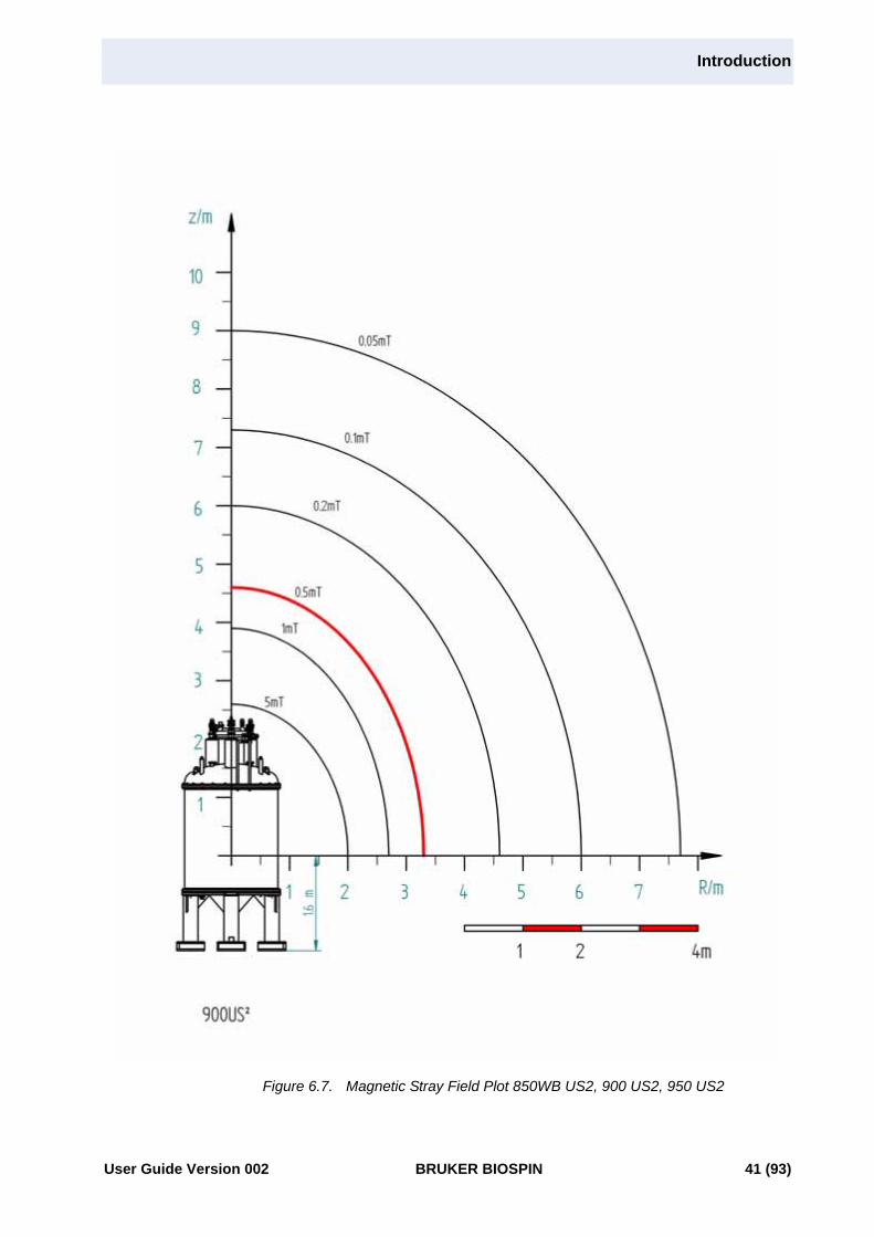
Figure 6.7. Magnetic Stray Field Plot 850WB US2, 900 US2, 950 US2
User Guide Version 002 BRUKER BIOSPIN 41 (93)

Magnetic Stray Fields
42 (93) BRUKER BIOSPIN User Guide Version 002

7Floor Plan 7
Size and Mass of Equipment 7.1
The floor of the NMR room must be sufficiently strong to support the console,magnet, and ancillary equipment. Table 7.1. gives the dimensions and weights ofNMR equipment. Table 7.2. gives the footprint and weight of magnets (filled withcryogens and including stand). The floor should also be as rigid as possible to re-duce the effect of vibrations.
Table 7.1. Dimensions and Weights of NMR Equipment
Component Width (m) Depth (m) Height (m) Weight (kg)
AVANCE Cabinet 1.31 0.83 1.55 454
Table / Workstation 1.20 1.00 0.75 68
Microimaging Cabinets 0.69 0.83 1.55 205 / 150
BMPC II 0.85 0.70 1.70 254
UPS - Main Unit- Battery Pack
0.320.34
0.690.62
0.720.79
165216
B-CU 05 0.50 0.55 0.48 50
For CryoProbe Option:
CryoCooling Unit 0.69 0.89 0.96 400
Helium CompressorIndoor Water Cooled 0.46 0.51 0.69 118
Helium CompressorOutdoor Air CooledIndoor partOutdoor part
0.310.92
0.610.41
0.311.05
11546
Helium CompressorIndoor Air Cooled 0.56 0.56 0.89 141
User Guide Version 002 BRUKER BIOSPIN 43 (93)

Floor Plan
The values in the following table correspond to Figure 7.1..
Figure 7.1. Magnet Dimensions
Table 7.2. Mass of UltraStabilized Magnets
Magnets
AMaximum
Magnet Diameter(m)
BMagnet Height from the Floor
Including Stand(m)
COverall Footprint
Diameter(m)
Total Magnet Weight Incl. Stand and Cryogens
(kg)
750 WB 1.295 3.641 1.818 4,400
800 1.295 3.641 1.818 4,200
800 US Plus 1.280 3.084 1.965 3,500
800 US2 1.688 3.865 2.10 5,900
850 US2 1.688 3.865 2.10 6,000
850 WB US2 1.688 3.865 2.10 7,300
900 1.688 3.865 2.10 6,000
900 US2 1.688 3.865 2.10 7,300
950 US2 1.688 3.865 2.10 7,300
US2= UltraShield-UltraStabilized; WB= Wide Bore (89 mm)
Refer to Table 7.2. for the values of A, B, and C for each magnet.
44 (93) BRUKER BIOSPIN User Guide Version 002

Magnet Location
Magnet Location 7.2
When locating the magnet, certain considerations must be made with regards tothe laboratory environment:
• To increase magnet homogeneity, the magnet should be located away frompermanent iron structures such as support beams in walls and floors. Refer-ence "Magnetic Environment" on page 59
• To increase temperature stability, the magnet should not be placed in directsunlight or near any artificial heat source. The magnet should also not beplaced under or in close proximity to air-vents or in an area that experiencesair drafts. Air should not be blown directly down or towards the NMR magnet.
• When possible, avoid a situation where a significant stray field (>5 G) extendsinto adjacent rooms.
• There should be free access to the magnet from all sides.
It is important to determine the optimal position in the NMR room, based on thefollowing orientation elements:
• The front of the manifold: The front of the He manifold is defined by a U-shaped opening. The manifold connects the three He turrets at the top of themagnet.
• The He fill port: The left turret (when looking at the front of the magnet) is thehelium fill port. It is necessary to provide a path to either the left side or thefront of the magnet so liquid helium transport dewars can be rolled in place.
• Magnet pump line: The magnet pump line connects to the back of the mani-fold (see Figure 7.2.).
• The front of the stand: The magnet stand also has a front side. The CryoPro-beTM transfer lines coming from the “Cryo” unit connect to the probe on thefront side of the magnet stand. The shim cable comes out through the backside, 180 degrees apart from the CryoProbe transfer lines.
NOTE: The front of the magnet stand does not necessarily have to match the frontof the manifold.
Figure 7.2. UltraStabilized Magnet Orientation
User Guide Version 002 BRUKER BIOSPIN 45 (93)

Floor Plan
Magnet Slab 7.3
In larger buildings, it is strongly recommended to design an isolated magnet slabthat separates (isolates) the magnet from the rest of the floor and building. Thisreduces vibrations that are transmitted to the magnet from the building (electro-mechanical equipment, HVAC, personnel, etc.). The slab must be large andstrong enough to safely support the load of the magnet.
It is important to achieve a full isolation of the slab on the sides as well as under-neath it in order to reduce both vertical and horizontal vibrations.
It is recommended to build first a thinner slab of ~15cm (6") on grade with a layerof sand underneath this slab. The main thick slab for the magnet would be addedon top of the thinner slab, and could be isolated from it with a pattern of smallpads made of special rubber isolation material. The main slab could be finishedon top with silicon filler. The separation gap on the sides can be filled with neo-prene or foam type material
The recommended dimensions are as follows:
750 WB, 800, and 800 US Plus: Length = 3.6 m (12’)Width = 3.6 m (12’)Depth = 0.3 m (1’)
800 US2, 850 US2, 850WB, 900, 900US2, and 950US2:
Length = 3.6 m (12’)Width = 3.6 m (12’)Depth = 0.6 m (1 1/2’)
NOTE: These dimensions are guidelines, not specifications, and remainsubject to approval by the project’s structural engineer.
Reinforcement: The slab must be reinforced with non-magnetic reinforcement(e.g. fiberglass, or non-magnetic stainless steel).
An isolated slab may not be necessary if the structure contains no sources of vi-brations, or if the foundation is on bedrock. In this case, it is still recommended toperform a vibration analysis. Please consult with Bruker BioSpin regarding themagnet slab and to arrange for analysis.
Please refer to "Vibrations" on page 57 for more information on vibration isola-tion and site analysis.
46 (93) BRUKER BIOSPIN User Guide Version 002

Magnet Platform
Magnet Platform 7.4
The purpose of a platform is provide safe access to the top of the magnet for sam-ple insertion, cryogen fills, etc. The basic design requirements for the platform in-clude, but are not limited to the following:
• Material: It must be non-magnetic. Wood and aluminum are used most often.
• Height of platform deck: The top of the deck must be located approx. at2.44m (8’) above the finished floor. The 800 US Plus does not require a plat-form given its compact size. An aluminum rolling ladder is sufficient.
• Railing: The height of the railing will be determined by local building codes.However, if the ceiling height is low it may be necessary to make a section ofthe railing removable. When the gantry is used to pick the magnet off the airskates, the cross-bar must not crush the railings.
• Footprint: The total footprint of the platform should be large enough to accom-modate a person, but small enough that the helium transfer line will reachacross the footprint without trouble. A footprint of 4m x 4m without taking intoaccount the stairs is generally adequate.
• Opening diameter: The circular opening must be centered with the magnetand have the following diameters:
- 750 WB and 800: 1.32m (52") diameter
- 800 US2, 850 US2, 850 WB, 900, 900 US2, and 950 US2: 1.71m (67") di-ameter
This will leave ca. 5 cm (2") clearance around the magnet cryostat, not theflanges. The diameter of the flanges is larger (please refer to the maxi-mum magnet diameter identified with „A“ in Figure 7.1. and correspond-ing Table 7.2..
• Border around the opening by the magnet and the outer platform rim:Borders, or lips, are recommended to prevent anything from falling off themagnet platform.
• Support posts: Given the larger magnet diameter at the flanges relative to theopening in the platform, care should be used when designing the support postto prevent obstructons. It is recommended to have the support posts awayfrom the magnet and closer to the outside perimeter of the platform to provideoptimal access to the bottom of the magnet and allow sufficient clearances foraccessories.
• Stairs: The access stairs shall be positioned to allow easy access to the frontof the upper manifold. This facilitates sample insertion.
• Magnet assembly time: As stated in "Rigging Equipment" on page 27, themagnet will be slid into place, and then a hydraulic gantry will be used to as-semble the magnet. For this reason, it is recommended to construct the plat-form in two parts. The first piece can be installed before the magnet isdelivered. The second piece should be installed shortly after the magnet hasbeen assembled. Please refer to "Magnet Installation Stages" on page 77for the stages of installation.
User Guide Version 002 BRUKER BIOSPIN 47 (93)

Floor Plan
Sample Changer Considerations 7.5
A B-ACS (Bruker Automatic Control System) has been developed for the UltraHigh Field magnet systems. This sample changer holds up to 60 NMR sampletubes and can be used the in conjunction with any of the ultra high field magnets.
This B-ACS utilizes a new kind of mechanical mounting equipment to attach thesample changer to the magnet. This allows for easy B-ACS adjustment in X, Y,and Z directions.
The mounting hardware descends along the Z-axis, down the front of the magnet.This may cause a slight interference with the decking of the magnet platform. Thiscould be solved by either lowering the height of the deck or implementing an addi-tional opening in the deck.
Magnet Pump Line 7.6
This section briefly describes the purpose, fabrication, and route of the pump line.
• Purpose: The pump line connects the pump to the Joule Thompson coolingunit located inside the helium dewar of the magnet system.
• Fabrication: It is custom-made out of stainless steel to fit site requirements.
• Route: The pump line connects the rear side of the helium manifold to theBMPC II cabinet. Most of the time it runs across the floor, although sometimesit is partially elevated:
- Keeping the pump line at floor level is the preferred route as it is the most ef-ficient way to prevent vibrations from entering the magnet. The pump line runsdown to the floor near the magnet stand, then continues across the floor to thewall. It runs along the wall to the BMPC II. A 15cm x 15 cm (6” x 6“) trenchwould be sufficient to conceal the pump line and sensor cable.
- It is always important to design the route to avoid tripping and obstructions,and to protect the pysical integritity of the pump line at all times.
48 (93) BRUKER BIOSPIN User Guide Version 002

Magnet Pits
Magnet Pits 7.7
If the ceiling height is not sufficient, and/or the stray fields in the room above arebeyond the acceptable range, then a magnet pit may be an option. Important is-sues that need attention include but are not limited to the following:
• Special rigging equipment and a temporary platform to support and lower mag-net inside the pit.
• Continuous ventilation and emergency exhaust inside the pit (please refer tospecial notes related to pits in sections 9.6 and 9.8 for HVAC and EmergencyGas Exhaust).
• Magnet refills and access for transport dewars.
• Cable lengths.
• Tuning and matching the probe.
• Siting the BCU05 cooling unit.
• Siting the CryoPlatformTM.
Consult your local Bruker Installation Engineer for pit design and construction de-tails.
Figure 7.3. Magnet in Pit with Customized Platform
User Guide Version 002 BRUKER BIOSPIN 49 (93)

Floor Plan
Maximum Field Strengths for NMR Equipment 7.8
Once the location of the magnet has been decided, it is time to determine wherethe remainder of the equipment will be placed. Protection of motors and electron-ics from magnetic stray fields is crucial.
Table 7.3. Maximum Field Strength for NMR Equipment
Unit Maximum Field Strength
Computers e.g. NMR workstation, PC 0.5 mT (5 G)
Printer Plotter 0.5 mT (5 G)
Gas cylinders 0.5 mT (5 G)
Heavy metal office furniture e.g. filing cabinet** 0.5 mT (5 G) - not recommended in magnet room
LC-NMR System & Accessories 0.5 mT (5 G)
He Compressor (CryoCooling) 0.5 mT (5 G)
Gilson 0.5 mT (5 G)
AVANCE cabinet 1.0 mT (10 G) line
TFT computer monitor 1.0 mT (10 G)*
BMPC II 1.0 mT (10 G)
BCU 05 5.0 mT (50G) - max. 2.7m from magnet center
CryoCooling unit 5.0 mT (50 G)
Movable metal chair not recommended in magnet room
* The working place for personnel should be outside the 0.5 mT (5 G) line. An additional TFT monitor and keyboard can be located at the 1.0 mT (10 G) line for probe adjustments etc.** Use wooden furniture if access during critical measurements is required.
50 (93) BRUKER BIOSPIN User Guide Version 002

Worktable Position
Worktable Position 7.9
Magnetic storage devices are sensitive to the stray field and attention must be giv-en to their position relative to the magnet.
• The flat LCD panel should be turned (or able to be turned) towards the magnetto facilitate tuning and matching.
• The workstation and additional disks, CD-ROM drives, etc., which are normallyplaced on the worktable, should not be exposed to fields greater than 1.0 mT(10 G).
• For convenience of operation, no direct light should fall on the LCD panel, norshould there be a strong light source at the back of the panel. A separate dim-mer or at least partial switching is recommended for the lights in the worktablearea.
Layout Examples 7.10
The following layout examples of an 800 US Plus, 850 US2, and 900 US NMRsystem include the equipment and utilities. A description of each of the NMR sys-tem components is presented in the chapter "Equipment" on page 17, while thedetails regarding the utility requirements are presented in the chapter "Utility Re-quirements" on page 65.
User Guide Version 002 BRUKER BIOSPIN 51 (93)

Floor Plan
The next table refers to the numbered items in the sample site layouts that follow.
Table 7.4. Utility Requirements
Device Number International America Purpose/Comments
UPS #1 230V, 50/60Hz 50A 1-Ph 208V, 60Hz, 60A, 1-Ph Disconnect, on emer-gency generator.
BMPC II #2 230, 50/60Hz, 32A 1-Ph 208V, 60Hz, 30A, 1-Ph, L6-30R
For installation and service.
#3 Distribution box for wire-in conduit (230V, 50/60Hz, 32A from BMPC to AVANCE),
J-box termination for wire-in conduit (208V, 60Hz, 30A from BMPC to AVANCE),
For providing power from BMPC to AVANCE.
#4 Analog fax modem line.
AVANCE #6 230V, 50/60Hz, 32A, 1-Ph
208V, 60Hz, 30A, 1-Ph, L6-30R
For installation and sevice
#7 Cekon connector, 1-Ph. Wire-in conduit coming from #3
L6-20R termination of wire-in conduit coming from #3
#8 Cable with Cekon male plug for wire-in conduit (to plug into Avance and feed BCU-05)
Cable with L6-20P ter-mination for wire-in conduit (to plug into Avance and feed BCU-05)
Power from Avance
#9 Regulated compressed gas 6.9 bar (100 psi).
BCU-05 #10 Cekon connector, 1-Ph. Wire-in conduit coming from #8
L6-20R termination of wire-in conduit coming from #8
Cryo Cool-ing Unit
#11 230V, 50/60Hz, 16A, 1-Ph
208V, 60Hz, 20A, 1-Ph, L6-20R
For buck-booster 208V/230V on sepa-rate UPS.
#12 Regulated compressed gas 4.1 bar (60 psi).
He Com-pressor
#13 400V, 50Hz, 30A (fused), 3-Phor 480V, 60Hz, 30A (fused), 3-Ph
208V, 60Hz, 60A (fused), 3-Ph
Disconnect, on emer-gency power.
Workstation #14 230V, 50/60Hz, 16A, 1-Ph
110V, 20A, 1-Ph On separate UPS
#15 Telephone port
#16 Data port
Imaging Accessory
230, 50/60Hz, 32A, 1-Ph 208V, 60Hz, 40A, 1-Ph Optional cabinet.
52 (93) BRUKER BIOSPIN User Guide Version 002

Layout Examples
Figure 7.4. AVANCE 800 US Plus NMR Layout Example
User Guide Version 002 BRUKER BIOSPIN 53 (93)

Floor Plan
Figure 7.5. AVANCE 900 UltraStabilized NMR Layout Example
54 (93) BRUKER BIOSPIN User Guide Version 002

Layout Examples
Figure 7.6. AVANCE 900 US2 NMR Layout Example
User Guide Version 002 BRUKER BIOSPIN 55 (93)

Floor Plan
56 (93) BRUKER BIOSPIN User Guide Version 002

8Environment and Site Survey Measurement 8
Introduction 8.1
This chapter covers the various site survey topics related to the NMR laboratory.The measurements and associated guidelines include:
• Vibrations
• Magnetic Environment
• Electromagnetic Interference: DC and 60Hz AC EMF
• RF Interference
The results of measurements carried-out during a site survey only reflect the spe-cific conditions that were present during the survey. Although these results areuseful as a reference, they would not be conclusive for the after-the-installationsystem performance if one or more site conditions change. These changes maybe related but not limited to sources of vibrations and electromagnetic field andRF interference like electro-mechanical equipment (HVAC, motors, pumps, freez-ers, etc.), elevators, car/bus/train traffic, power lines, transformers, radio/TV sta-tions and other possible RF sources, etc.
Vibrations 8.2
External vibrations may cause field modulations in the sample cavity. This couldresult in vibration sidebands, matched NMR signals that appear on either side of amain signal peak.
• Ideally the site should be at basement level to minimize building vibrations.
• Possible sources of vibrations are generators, compressors, fans, machineryetc. Vibrations from external sources such as cars, trains, airplanes, and con-struction sites can also cause problems.
User Guide Version 002 BRUKER BIOSPIN 57 (93)

Environment and Site Survey Measurement
• Measuring the extent of vibrations at the magnet location is a relatively simplematter; if you suspect that a problem you should contact your local Bruker Bio-spin office.
• Various measures to dampen floor vibrations are available. Please refer to "Vi-bration Damping Measures" on page 58.
Vibration Guidelines 8.2.1
Measurements of floor accelerations (mm/sec2) are required in both vertical andhorizontal directions over a minimum frequency range of 0 to 100 Hz. Recordingboth average and peak-hold values is recommended.
All magnets are equipped with vibration dampers in order to reduce vibrations onthe magnet. The isolation performance is given by a transmissibility characteristicfor the specific dampers integrated within the magnet. The higher the frequency offloor vibrations, the better the damping (less of the vibration is transmitted). Also,the smaller the natural frequency of the dampers and the smaller their “Q” (ampli-fication factor at the natural frequency), the higher the isolation performance.
The acceleration peaks measured directly on the proposed magnet floor must bemultiplied by the transmissibility factor of the dampers at the specific frequenciesat which these acceleration peaks have been recorded. The results must then becompared to the maximum 0.1 mm/sec2 that can be tolerated at the magnet.
Vibration Damping Measures 8.2.2
All UltraStabilized magnet systems are equipped with pneumatic vibration damp-ers (vibration isolation units). Two options are available:
• Air-Spring dampers have a natural frequency of ~2.5 Hz and become effectiveat floor vibration frequencies above 4 Hz.
• Advanced dampers - vibration isolation columns having a natural frequencybelow 1.5Hz, and become effective at floor vibration frequencies above 2.5 Hz.This superior isolation solution is suitable for very low frequency vibrations(vertical and horizontal).
It is strongly recommended to design an isolated magnet slab that separates (iso-lates) the magnet from the rest of the floor and building. This should reduce themagnitude of vibrations that are transmitted to the magnet from the building (elec-tromechanical equipment, HVAC, personnel, etc.). For guidelines on the magnetslab please refer to the section "Magnet Slab" on page 46.
58 (93) BRUKER BIOSPIN User Guide Version 002
Magnetic Environment
Magnetic Environment 8.3
The presence of any ferromagnetic materials in the immediate vicinity of the mag-net will decrease the magnet´s homogeneity and may degrade overall perfor-mance. Although minimum requirements for routine NMR are not stringent, themagnetic environment must be optimized if more sophisticated experiments arebeing carried out. Usually, the effect of metal pipes, radiators, and other such ob-jects can be “shimmed out”, but whenever possible, this should be avoided.
To assist in site planning two sets of guidelines are given below: “minimum re-quirements” and “acceptable environment”.
If minimum requirements can not be met, the customer should consider adifferent site because NMR performance is likely to be reduced. By accept-able environment we mean an environment with which most customer sitescomply. This is a situation which is desirable, though not always achiev-able.
Minimum Requirements 8.3.1
Static Iron DistributionAny iron within the confines of the NMR lab should be located at least 3.66m (12’)from the center of the magnet. Removal of iron piping in this vicinity should beconsidered prior to installation. If the magnet must be located close to iron or steelsupport beams proper alignment is important; support beams should passthrough or be symmetric to the magnet axis.
Any static iron mass (0-227kg/0-500lbs.) must be at least at 3.66m (12’) from themagnet center. For heavier masses, the limiting area must be extended accord-ingly. The presence of static magnetic material near the magnet assumes thatthese masses are firmly secured e.g. radiators, pipes.
Moveable Magnetic MaterialNo moveable masses should be located within a ~6.1 m (20’) radius. Potentialsources of moving iron are metal doors, drawers, tables, chairs etc. For larger ironmasses (> 227 kg/500 lbs.) distorting effects may be experienced when thosemasses are moving as far as 12.2 m (40’) or more from the magnetic center.
For high precision work (e.g. NOE difference experiments) increasing the exclu-sion zone for moveable magnetic material may be justified.
User Guide Version 002 BRUKER BIOSPIN 59 (93)

Environment and Site Survey Measurement
Acceptable Environment 8.3.2
Static ObjectsTable 8.1. gives a list of common sources of magnetic interference. These itemsshould be located according to the recommendations below. It must be empha-sized however, that such recommendations represent a situation that may not beachievable. Please consult with Bruker BioSpin for possible solutions if one ormore of these recommendations cannot be satisfied.
Table 8.1. Recommendations for Static Magnetic Objects
Moving ObjectsThe table below serves as a guideline for moveable magnetic material.
Table 8.2. Recommendations for Moveable Magnetic Objects
* Note that D.C. operated elevators, trains, and trams may cause disturbancesover much larger distances (see Table 8.3.). In addition, these may also cause vi-brational disturbances.
Object Actual distance from magnetic center (m)
Iron or steel Beams 4
Steel reinforced walls 4
Radiators, Plumbing pipes 4
Metal table, metal door 4
Filing cabinet, steel cabinet 4
Massive objects e.g. Boiler 4
Object Actual distance from magnetic center (m)
Steel cabinet doors 6
Large metal door, hand trolley 9
Elevators* 12
Cars, Fork-lifts 12
Trains, Subways, Trams* 30
60 (93) BRUKER BIOSPIN User Guide Version 002

Electromagnetic Interference
Electromagnetic Interference 8.4
Possible sources of interference are power lines which may carry fluctuatingloads, heavy duty transformers, large electric motors, air conditioning systems,power transformers, etc. The fluctuating electromagnetic fields arising from suchdevices can interfere with the magnet homogeneity. Of particular concern aresudden changes in load as may be produced by elevators, trams, subways etc.Some laboratory equipment such as mass spectrometers and centrifuges will alsogive rise to fluctuating fields. Other sources of interference include radio and tele-vision stations, satellites and other RF transmitters that may operate in the vicinityof NMR frequencies of interest.
If you suspect that you have a source of interference located near the pro-posed magnet site then you should contact Bruker Biospin for a site survey.
Types of EMF Interference• DC Interference
• 50/60 Hz Interference
• RF Interference
DC EMF Interference 8.4.1
DC interference generally comes from devices operated on DC, such as eleva-tors, trains, subways, trams, etc. The locations of both the device and its powersupply & lines relative to the proposed NMR site are essential to the amplitudeand orientation of DC fields and how they may interfere with the NMR system. DCfeeder lines are just as disturbing as a subway, and they do not run necessarilyparallel to the track.
Measuring DC Fluctuating FieldsDC EMF measurements should be conducted using a fluxgate magnetometer.The fluxgate sensor is capable of accurately measuring magnetic field changesbelow 1mG. The sensor is connected to a magnetometer, and the voltage outputfrom the meter is then converted into digital form. The magnetic field is recordedand plotted on a computer display in real time.
Reducing DC InterferenceThe amplitude of the “full external perturbation” (peak-to-peak) is measured withthe fluxgate magnetometer at the proposed magnet location but in the absence ofmagnet. There are two levels of compensation against these external DC fieldperturbations:
1. First, the magnet screens itself against external perturbations, hence only afraction of the full perturbation is left at the magnet center. We call this residualfield perturbation after magnet screening. It’s value is relevant to NMR experi-ments without lock, relevant to many solids experiments and high resolutionexperiments using gradients which require lock hold.
2. Second, the advanced digital NMR lock further minimizes the interference aftermagnet screening. The digital lock is less susceptible to field perturbationsthan the older analog lock. The final response may depend on the lock sub-stance and concentration.
User Guide Version 002 BRUKER BIOSPIN 61 (93)

Environment and Site Survey Measurement
Guidelines: DC InterferenceWhen determining the effect of fluctuating magnetic fields, two parameters are im-portant: the size of the fluctuation and the rate of change.
• Field changes of up to 5 mG, regardless of the rate of change, are generallyconsidered harmless for standard NMR work.
• Field changes larger than 5 mG will be compensated by the digital NMR lock,as long as their rate of change is less than 10 mG/sec.
• Field changes faster than 10 mG/sec need to be addressed in more detailalong with the types of NMR experiments to be performed, in order to betterassess whether the NMR performance will be affected. Please consult withBruker Biospin to assess the level of interference and explore solutions.
Table 8.3. lists the minimum distances between the source of interference andthe magnet center.
* Elevators, trains, subways, and trams are also a source of vibrational interfer-ence.
50/60 Hz EMF Interference 8.4.2
The 50/60 Hz interference generally comes from electrical wiring, transformersand fluorescent lights located in the vicinity of the magnet as well as near theNMR cabinet and workstation. The magnetic field further modulates this interfer-ence, increasing the likelihood of disturbances.
Measuring 50/60 Hz Fluctuating FieldsThe amplitude and orientation of the 50/60 Hz fluctuating fields should be mappedwithin the proposed NMR room. The sources of such fields should be identified.Specific locations that must be checked carefully include:
• Magnet area
• Console area
• Along the wall inside the NMR room at 5 cm (~2”) from wall, and 3.8 cm (4”)from wall
• Approximately 5 cm (~2”) below the existing lights in the room
• Near the main outlets 230V (USA - 208V) locations in the room.
Table 8.3. Minimum Distances from Sources of DC EMF Interference
Source of InterferenceRecommended Minimum
Distance from Magnet Center (m)
DC Trains, subways, trams* 150
DC Elevators* 12
Mass Spectrometer (slow ramp) 12
Mass Spectrometer (sudden flyback) 30
62 (93) BRUKER BIOSPIN User Guide Version 002

Electromagnetic Interference
Guidelines: 50/60 Hz InterferenceThe amplitude at which interference is likely is ~ 1.8mG RMS. Since this ampli-tude is based on laboratory tests, ideal values should be well below 1.8 mG RMS.
The magnet should not be placed within a 6.1 m (20’) radius of a normally-sizedtransformer. If there is a large transformer adjacent to the proposed magnet loca-tion, measurements will be required to determine if the transformer will adverselyaffect NMR spectra.
The magnet should not be placed directly under fluorescent lights. Fluorescentlighting may cause interference, and may switch off temporarily during a quench.
RF Interference 8.4.3
The NMR instrument is effectively a very sensitive radio frequency receiver. Pos-sible sources of interference are local radio or television broadcasts, low Earth or-bit satellite systems, and signals emitted by personal paging systems. Ofparticular concern will be interference at frequencies at which NMR experimentsare carried out. Although the interference effects will depend greatly on thestrength of the transmitter, as a rule of thumb only broadcasting transmitters locat-ed within a radius of approximately 5 kilometers (3 miles) are likely sources of in-terference.
RF interference may also occur between two or more spectrometers located inclose proximity and operating at the same nominal 1H resonance frequency.
Measuring RF Fluctuating FieldsRadio Frequency Interference measurements should be conducted using a spec-trum analyzer. The analysis should be done for the resonance frequency of eachof the nuclei of interest (proportional to the 1H resonance frequency of the spec-trometer). The minimum frequency sweep is 400 kHz. Any peaks with RF fieldsabove -80 dBm should be recorded, as well as any broad frequency ranges withany level of RF signals.
"Table 8.4." on page 64 contains a list of the most common studied nuclei at thecorresponding frequencies for the 750, 800, 850, and 900 MHz NMR systems.
Guidelines: RF InterferenceAs a general guideline the level of any RF interference should be less than anelectrical field strength of -65 dBm at the side of the magnet. However, past expe-rience has shown that broadband RF fields having smaller intensity (about -80dBm) may interfere with the NMR experiments. Therefore, it is important tomake a note of any measurements exceeding -80 dBm.
Reducing RF InterferenceScreening a site for possible RF Interference is complicated and expensive.Shielding of the NMR room with a Faraday cage is a possible solution, thoughhaving to take such measures is quite rare.
When designing and manufacturing the Bruker BioSpin spectrometers, care istaken to provide adequate shielding and the instruments rarely suffer from inter-ference in normal RF environments. Furthermore, the advanced BSMS digitallock system - included with all Bruker BioSpin AVANCE spectrometers - allows ashift in the 2H lock frequency with certain limits. This may allow enough variation
User Guide Version 002 BRUKER BIOSPIN 63 (93)

Environment and Site Survey Measurement
in the absolute magnet field strength to shift the NMR signal away from that of lo-cal broadcasting frequencies.
RF interference may occur between two or more spectrometers located in closeproximity and operating at the same nominal 1H resonance frequency. Theseproblems can be avoided by energizing the different magnets at slightly differentfields, such that their operational frequencies are separated by ~ 200 kHz of thenominal 1H resonance frequency.
Table 8.4. List of Most Commonly Studied Nuclei and Corresponding Resonance Frequencies
Nuclei NMR Frequency (MHz)
Magnets 750 800 850 900
1H 750.131 800.131 850.131 900.131
2H 115.151 122.827 130.502 138.177
11B 240.697 256.740 272.786 288.828
13C 188.631 201.204 213.777 226.350
15N 76.145 81.221 86.285 91.372
19F 705.948 753.003 800.055 847.113
27Al 195.603 208.647 221.687 234.718
29Si 149.202 159.147 169.094 179.037
31P 303.963 324.224 344.488 364.745
64 (93) BRUKER BIOSPIN User Guide Version 002
9Utility Requirements 9
Electrical Power Requirements 9.1
The Bruker UltraStabilized systems operate at a reduced temperature which canonly be maintained by uninterrupted power to one helium pump. These systemswill stay operational for several hours, but it requires a knowledgeable person tobring them back to normal operating conditions. A longer failure of the coolingsystem will inevitably result in a quench. In such a failure, the system may bedown for several weeks and will require reinstallation.
The standard system is equipped with 9 hours of backup capacity for the magnetpump assembly. If power failures longer than 9 hours are likely in the area of in-stallation, it is the responsibility of the customer to take appropriate provisions.
The power for the AVANCE UltraStabilized NMR systems is exclusively controlledby the BMPC (Bruker Monitoring and Pump Control) Unit. This unit provides therequired power to the main AVANCE two-bay cabinet, the cooling pumps, and an-cillary units such as the BCU-05 cooling unit.
Table 7.4. includes the electrical power requirements.
Figure 9.1. displays the BMPC and the various units to which it distributes power.
Other important considerations include:
• All power is routed through the UPS which also has the advantage of servingas a line conditioner. In the event of a power failure, the power source auto-matically switches to the UPS batteries.
• Though the UPS is hard wired to a distribution box which feeds the BMPC andthe Avance console, the power for the Avance console is still exclusively con-trolled by the BMPC.
• If the power failure exceeds 6 minutes, the supply to the two-bay cabinet willbe cut off automatically. This will enable the UPS to power the helium pump forabout 9 hours. As most (more than 90%) power failures are much shorter than6 minutes, this compromise reserves most of the battery capacity for the mag-net and allows NMR measurements to run undisturbed in case of short powerinterruptions.
User Guide Version 002 BRUKER BIOSPIN 65 (93)

Utility Requirements
• If the power failure exceeds 9 hours, it is recommended to provide backupemergency power to maintain the operation of the helium pumps. This powercan come from the building’s emergency generator or from a small, dedicatedgenerator. If a power failure continues for more than 4 hours, the customer willbe alarmed by telephone through the Bruker Monitoring System (BMS).
• Standard-length power and communication cables are provided with the instru-ment. If the placement of the NMR cabinets does not allow for the use of thesecables, the customer may be required to provide electrical power conduits.
Figure 9.1. Main Electrical Power Requirements Flowchart
The AVANCE cabinet comes supplied with four electrical outlets (230V/16A - Eu-ropean Shuko receptacles) which can be used to power standard ancillary equip-ment. Two outlets are designed to power the NMR Workstation and (optional)Imaging Cabinet. This leaves two outlets free for accessories such as the BCU-05or Automatic Sample Changer etc.
Telecommunication 9.2
Please refer to the AVANCE UltraStabilized NMR layout in "Layout Examples"on page 51. The following ports are required:
• Telephone/data ports behind the workstation
Main Supply230V 50A
(208V 40A)Disconnect
UPS8.5 KVA
DistributionBox
BMPC IIincluding pumpsI
Backup Generator230V 32A
(208V 40A)AVANCE
2.2-9.6 kW NMRWorkstation
Available230V 16A
(208V 20A)
Available230V 16A
(208V 20A)
BCU-050.45 kW
Notes:- Values in parathesis are for America.- 230V 16A (208V 20A) outlets should be plentiful.- The AVANCE console has 3 outlets that may be used for Bruker equipment.- Service outlets are used for matintenance purposes.
Service Outlet230V 32A
(208V 30A)AVANCE
Service Outlet230V 32A
(208V 30A)
Outlet230V 16A
(110V 20A)
66 (93) BRUKER BIOSPIN User Guide Version 002

Compressed Gas
• Dedicated analog modem (telefax) port behind the monitoring unit (BMPC).
Compressed Gas 9.3
General RequirementsCompressed gas line: The standard AVANCE system requires one compressedgas line with two regulated outputs. Two additional secondary connectors are per-ferred.
Regulators: Watts Regulator R119-03C (Watts Fluid Air Company), pressurerange 0-8.6 bar (0 - 125 psi), with gage head included.
• Compressed nitrogen gas needed for temperature control with VT experimentsin order to achieve optimal NMR performance. The BCU-05 cooling unit re-quires a DEW point of -51°C (-60°F) for the compressed gas.
• Compressed air or nitrogen gas for spinning.
• Compressed air or nitrogen gas for sample ejection, and for the magnet’s vi-bration isolation units.
• Compressed air or nitrogen gas for the optional CryoProbe system.
Compressed Gas Options 9.3.1
Option 1 (preferred):
Nitrogen gas only: 57 l/min. (2 scfm) for non-MAS experiments, or 227 l/min. (8scfm) for MAS experiments. The pressure should be 6-8 bar (80-120 psi).
Option 2: Nitrogen gas for VT work only: flow 5.7-34 l/min. (0.2 - 1.2 scfm), minimum pres-sure 4.2 bar (60 psi). This can be provided by a nitrogen separator or using boil-off from a LN2 dewar.
Dry air for the rest: 22.7-51 l/min. (0.8-1.8 scfm) for liquid NMR experiments, 193-221 l/min. (6.8-7.8 scfm) for MAS experiments. Pressure 6-8 bar (80-120 psi).
Option 3 (not recommended unless exclusive use of a CryoProbe isexpected)Dry air only: minimum flow 85 l/min. (3 scfm) for non-MAS experiments, 255 l/min.(9 scfm) for MAS experimetns. The pressure should be 6-8 bar (80-120) psi.
Note:A nitrogen separator (supplied by Bruker BioSpin) can be built into the AVANCEcabinet as an available solution for option 3. This will produce the nitrogen gas re-quired for VT work. However, this is not suitable for larger flow rates required byMAS experiments.
The nitrogen separator is suitable for use with the BCU-05 cooling unit. Howeverthe nitrogen output from the separator is not pure enough and this unit should notbe used with a N2 exchanger or BCU-X cooling unit for low temperature work.
User Guide Version 002 BRUKER BIOSPIN 67 (93)
Utility Requirements
Gas Requirements For Accessories 9.3.2
• If use of a Bruker Automatic Sample Changer (BACS) in high throughput modeis planned, a secondary regulator, T-split from the supply line, is recommend-ed.
• For MAS (Double Bearing) a second regulator is mandatory. Make sure thesupply line cross-section is sufficient to deliver the necessary volume at the re-quired pressure.
• If a CryoCooling unit is to be installed, a secondary regulator, T-split from thesupply line is recommended.
• If the Emergency Sample Protection Device is to be used in conjunction withthe CryoProbe System, a cylinder of air or nitrogen gas is required.
Compressed Gas Specifications 9.3.3
Oil Content: < 0.005 ppm (0.005 mg/m3)
Water Content
For the BCU05 cooling unit the compressed gas should have a DEW Pointof -51°C (–60°F). For the BCU-X cooling unit, the DEW Point requirement is-100°C (-148°F).
For room temperature work and higher: DEW Point of < 4°C (39.2°F)
For low temperature work: The DEW Point must be at least 20°C (68°F) be-low the operating temperature.
If a cooling unit is used, then the DEW Point of the compressed nitrogenshould be at least 10°C (50°F) below the temperature at the heat exchang-er output.
Solid ImpuritiesUse 5 micron filters for high resolution NMR. For MAS probes use 1 micronfilters. The filters should retain a minimum of 99.99% of the specified parti-cles.
68 (93) BRUKER BIOSPIN User Guide Version 002

Compressed Gas
Air Compressors 9.3.4
When choosing an air compressor the following points should be considered:
1. Ideally the compressor should be installed in a dust free, cool and dry place.
2. The compressor must be oil-free. This can be achieved by using membrane orTeflon coated piston compressors. The compressor should be fitted with a finedust inlet filter.
3. The compressor must be capable of delivering the required flow rate and pres-sure suited to your particular system (see Table 9.1.). Generally the compres-sor should be large enough so it does not run continuously (e.g. > 50% of thetime), which will cause overheating.
The extra cost of choosing an oversized system may often be justified. The re-duction in duty cycles will lower maintenance costs and extend the life of thesystem. A suitable compressor coupled to an adequate buffer will ensure amore constant flow rate leading to better performance. When spinning, thesystem uses a constant flow of air, but surges will occur during sample lift.When referring to Table 9.1. you should add on 10 l/min. to the average con-sumption if the system is fitted with anti-vibration devices such as pneumaticdampers or a VIP system.
4. Take into account the pressure loss along the line between the compressorand the final gate valve. The pressure drop depends on the pipe diameters. Aninternal diameter of 8 mm has been found to be suitable. The plastic tubingused to carry the supply from the final gate valve to the console has an outsidediameter of 8 mm and is supplied by Bruker BioSpin.
5. Some types of dryers, e.g., absorption dryers can use up to 25% of the air flowto regenerate the drying material. If this type of dryer is used then the outputcapacity of the compressor must be sufficient to supply this requirement.
Table 9.1. Compressed Gas Requirements
System Operating Pressure Average Consumption
Recommended Minimum Gas Supply***
Two-Bay 6-8 bar (80-120 psi) 45 l/min. (~1.6 cfm) 57 l/min. (~2 cfm)
Two-Bay + BACS* or NMR CASE
6-8 bar (80-120 psi) 52 l/min. (~1.8 cfm) 57 l/min. (~2 cfm)
Two-Bay + MAS (DB**) 6-8 bar (80-120 psi) 220 l/min. (~8 cfm) 300 l/min. (~11 cfm)
* Bruker Automatic Sample Changer** DB= Double Bearing*** This is the actual consumption and minimum needed at the instrument input after the N2 supply
(either a bulk tank, or a N2 separator).
For non-MAS work, if a an air-compressor and N2 separator are used, the flow requirements are 50% higher, i.e. 3 cfm. It is recommended to use a dual unit oil-less air-compressor rated at min. double capacity of the specified requirement. Please refer to the next section on air compressors.
User Guide Version 002 BRUKER BIOSPIN 69 (93)
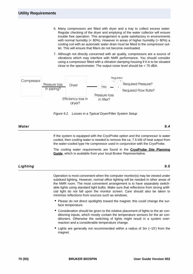
Utility Requirements
6. Many compressors are fitted with dryer and a tray to collect excess water.Regular checking of the dryer and emptying of the water collector will ensuretrouble free operation. This arrangement is quite satisfactory in environmentswith normal humidity (< 80%). However in areas of higher humidity (> 80%) acooling coil with an automatic water drain must be fitted to the compressor out-let. This will ensure that filters do not become overloaded.
7. Although not directly concerned with air quality, compressors are a source ofvibrations which may interfere with NMR performance. You should considerusing a compressor fitted with a vibration damping housing if it is to be situatedclose to the spectrometer. The output noise level should be < 75 dBA.
Figure 9.2. Losses in a Typical Dryer/Filter System Setup
Water 9.4
If the system is equipped with the CryoProbe option and the compressor is watercooled, then cooling water is needed to remove the ca. 7.5 kW of heat output fromthe water-cooled type He compressor used in conjunction with the CryoProbe.
The cooling water requirements are found in the CryoProbe Site PlanningGuide, which is available from your local Bruker Representative.
Lighting 9.5
Operation is most convenient when the computer monitor(s) may be viewed undersubdued lighting. However, normal office lighting will be needed in other areas ofthe NMR room. The most convenient arrangement is to have separately switch-able lights using standard light bulbs. Make sure that reflections from strong artifi-cial light do not fall upon the monitor screen. Care should also be taken tominimize reflections from sources such as windows.
• Please do not direct spotlights toward the magnet; this could change the sur-face temperature.
• Consideration should be given to the relative placement of lights to the air con-ditioning inputs, which mostly contain the temperature sensors for the air con-ditioners. Otherwise the switching of lights might result in a system over-reaction and a considerable temperature change.
• Lights are generally not recommended within a radius of 3m (~10’) from themagnet.
70 (93) BRUKER BIOSPIN User Guide Version 002

HVAC (Heating Ventilation Air Conditioning)
HVAC (Heating Ventilation Air Conditioning) 9.6
Constant temperature and humidity is crucial for high performance operation.
Room temperature should be kept between 63 and 77°F.
Room temperature should not fluctuate more than +/-0.5 °C (1°F) per hour. Nearthe magnet or cabinets, the temperature fluctuation should not exceed +/-0.5°C(1°F). Air drafts, particularly those created from air conditioning or heating sys-tems, can have negative effects on the magnet.
The location and orientation of air-diffusers must prevent the air from blowing to-wards the magnet and spectrometer cabinet, since this would have a negative im-pact on the system stability and its performance.
The heat output of the standard AVANCE UltraStabilized system for high resolu-tion work is about 4.6 kW (18,000 BTU/hr.). This includes the main AVANCE cabi-net, the BMPC, the BCU-05, and the workstation.
The heat output of the AVANCE UltraStabilized system equipped with High Poweramplifiers for solids NMR is between 6 kW (25,000 BTU/hr.) to 10 kW (40,000BTU/hr.) depending on the high power configuration.
Humidity should be kept between 30% and 80%. Conditions other than these maywarrant the installation of an air conditioner with appropriate humidity controls.
Magnet Stability: The heat output is constant and it is essential to minimize oravoid short term oscillations of the HVAC system, and provide a continuous slowflow of air that in turn reduces the speed of any temperature changes. In otherwords, it is recommended to have a continuous and slow exchange of air in theNMR room, hence minimizing fluctuations.
Most of the heat is generated in the AVANCE cabinet, the magnet pump assem-bly and the BCU05. The magnet itself does not dissipate any heat. Special careshould be taken so the air does not blow towards the magnet and spectrometercabinet.
Pits: When a magnet is installed in a pit, it is important to ensure there is continu-ous air-flow (or exhaust) within the pit. This is done to prevent any buildup of nitro-gen gas in the confines of the pit, not to reduce the temperature stability of themagnet. If more circulation is required, emergency exhaust will be discussed inSection 9.8: "Emergency Gas Exhaust"
User Guide Version 002 BRUKER BIOSPIN 71 (93)

Utility Requirements
Fire Detection System and Fire Extinguishers 9.7
Rooms containing NMR magnets should be equipped with temperature sensorsfor fire detection. These must respond only to a sudden rise of temperature, andnot be triggered by a quench (sudden drop of temperature).
Optical sensors cannot discriminate between smoke from a fire and fog caused bya quench so these may not be used.
Fire extinguishers in the vicinity of the magnet room must be non-magnetic(stainless steel or aluminum). It is the obligation of the customer to inform the lo-cal fire department about the dangers of magnetic fields. These magnets stay atfield for a long time even in a most blazing fire!
Ceiling sprinkler heads should be made of metal instead of glass. A quench couldfalsely trigger the alcohol-filled glass vials, which can shatter in the presence ofcold helium gas. Sprinklers should not be located directly over the magnet.
Any sprinkler lines or other metal pipes located above the magnet should be ther-mally-insulated to prevent O2 condensation or water freezing in the line from thelarge amount of cold He gas following a magnet quench.
Emergency Gas Exhaust 9.8
Due to the large amount of liquid He contained in the magnet, an emergency ex-haust system may be required to prevent O2 depletion during a magnet quench.Table 9.2. lists the amount of LHe and He gas after a quench for the UltraStabi-lized magnets.
Regarding the emergency gas exhaust, important considerations include, but arenot limited to, the following:
• Amount of liquid He: Taking the 850 US2 magnet as an example, the totalamount of liquid He is 1200 liters. In case of a quench, the liquid transformsinto gas and expands by a factor of 740. Therefore, the total amount of Heevaporated gas in case of a quench will be ca. 888 m3 (31,400 ft3).
Table 9.2. He Gas After a Quench
UltraStabilized magnets
Amount LHe (liters)
He gas after a quench(per minute)
750 WB ~ 450 333 m3 (~11,800 ft3)
800 ~ 450 333 m3 (~11,800 ft3)
800 US Plus ~ 350 296 m3 (~10,500 ft3)
800US2 ~ 1,200 888 m3 (~31,400 ft3)
850 US2 ~ 1,200 888 m3 (~31,400 ft3)
850WB US2 ~ 1200 518 m3 (~18,300 ft3)
900 ~ 800 518 m3 (~18,300 ft3)
900 US2 ~ 1300 518 m3 (~18,300 ft3)
950 US2 ~ 1300 518 m3 (~18,300 ft3)
72 (93) BRUKER BIOSPIN User Guide Version 002

Emergency Gas Exhaust
• Maximum He gas flow: The maximum flow of He gas is calculated on the as-sumption that half of the volume of liquid evaporates in 1 minute, thus the max-imum flow would be 444 m3 (15,700 ft3) for the 850 US2 magnet. The gasshould be removed from the room immediately through an emergency exhaustsystem.
• O2 level sensors: Oxygen level sensors are required to detect low O2 levelswithin the NMR room for each system. One sensor is needed above the mag-net for detecting low O2 levels due to He gas exhaust in case of a quench orduring He fills. An additional sensor is needed close to the floor for detectinglow O2 levels due to N2 gas exhaust during magnet cooling or regular N2 fills.In case of placing the magnet inside a pit, a third sensor is needed inside a pitto detect low O2 levels from N2 gas.
• Emergency exhaust solutions: The following exhaust solutions are recom-mended:
Passive exhaust: This system is based on louvers in the ceiling, or upperparts of outside walls, that open up due to the pressure of He gas.
Active exhaust: In addition, an active system based on a motorized fan in,or close to, the ceiling is recommended. This way, adequate exhaust ofcryogenic gases will be provided not only during a quench, but also duringthe initial cooling of the magnet and regular cryogen refills.
Normally it is sufficient to operate this fan manually, as the probability of anunattended quench after the installation is rather low.
If desired, this fan can be operated with an automatic switch:
a) it should be installed in addition to a manual switch.
b) measures should be taken to prevent it from being turned on duringa fire.
Quench pipes: This solution may be required when the NMR room is smalland any of the other options are not sufficient to ensure safety after a mag-net quench.
This solution is based on a pipe connected directly to the magnet, which isthen routed to the outside of the building. It is important to note the follow-ing:
- The helium exhaust from the magnet should be vented directly to the out-side of the building.
- The ducts should have sufficient diameter to avoid excessive pressurebuild-up due to the flow impedance of the duct.
- The location of the exit end of the duct must not be accessible to anyoneother than service personnel. In addition the exit opening should be pro-tected from the ingress of rain, snow, animals, etc.
- It is also essential that any gas which vents from the exhaust duct cannotbe drawn into the air conditioning or ventilation system intakes. The loca-tion of the duct’s output should be carefully sited to prevent this from hap-pening during any adverse atmospheric conditions and winds.
User Guide Version 002 BRUKER BIOSPIN 73 (93)
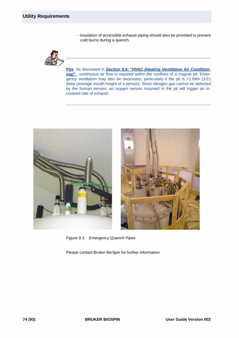
Utility Requirements
- Insulation of accessible exhaust piping should also be provided to preventcold burns during a quench.
Pits: As discussed in Section 9.6: "HVAC (Heating Ventilation Air Condition-ing)" , continuous air flow is required within the confines of a magnet pit. Emer-gency ventilation may also be necessary, particularly if the pit is >1.09m (3.5’)deep (average mouth-height of a person). Since nitrogen gas cannot be detectedby the human senses, an oxygen sensor mounted in the pit will trigger an in-creased rate of exhaust.
Figure 9.3. Emergency Quench Pipes
Please contact Bruker BioSpin for further information.
74 (93) BRUKER BIOSPIN User Guide Version 002
Oxygen Monitor and Level Sensors
Oxygen Monitor and Level Sensors 9.9
Oxygen monitors or level sensors are required inside the magnet room. The mini-mum number of oxygen sensors follows:
Above the mag-net on the wall:
One oxygen level sensor should be above the magnet, to detect low oxygen levels caused by high He gas levels.
Close to the floor on the wall:
One oxygen level sensor approx. 30 cm off the floor of the magnet room.
Down in the pit: One additional oxygen level sensor approximately 30 cm off the bottom of the pit, in case the magnet is located inside a pit.
User Guide Version 002 BRUKER BIOSPIN 75 (93)

Utility Requirements
76 (93) BRUKER BIOSPIN User Guide Version 002

10Installation 10
Introduction 10.1
Please fill out and return the Site Planning Checklist prior to the delivery of themagnet system. If this checklist was not provided, please contact your Bruker Bio-Spin representative immediately.
All general requirements such as power supply, compressed air supply, etc. mustbe installed before the system can be delivered. Installation requirements such ascryogen supplies are totally separate from normal operation requirements. Thesystem can only be delivered and installed after the completion of all constructionwork in the lab. The lab must be cleaned from all remaining dirt, dust, particles,etc.
The magnet transport crates should be kept indoors out of direct sunlight. Thecrates should not be opened until a Bruker BioSpin magnet engineer arrives. Fail-ure to do so may invalidate the warranty. The crates are shipped with Shock-watchTM and TiltwatchTM indicators.
Overview 10.2
The spectrometer system will arrive at the site in crates. The crates should onlybe opened by the Bruker BioSpin service engineer. The commissioning of themagnet involves several stages as outlined in Table 10.1.. The installation time-line given below is an approximation; each site is slightly different.
Table 10.1. Magnet Installation Stages
Days Procedures
Day 1 Delivery of the magnet
Days 2 - 5 Assembly of the magnet
Days 6 - 12 Flushing, vacuum, leak detection, installation of the pump line
Days 13 - 17 Precooling with liquid N2
Days 18 - 19 Cooling with liquid He
Days 20 - 23 Subcooling to reduced temperature
Days 24 - 38 Energizing and Cryoshimming
Days 38 - 48 Running NMR experiments to demonstrate standard specifica-tions.
User Guide Version 002 BRUKER BIOSPIN 77 (93)

Installation
Accessibility 10.3
Before the arrival on site, the customer must ensure the equipment can be deliv-ered, and transported safely to the final location inside the NMR room. Please re-fer to "Magnet Access and Rigging" on page 23 for the details.
Checklist of Installation Requirements 10.4
For the installation the customer must provide the following:
• Lifting equipment and minimum ceiling height as outlined in Table 10.2.
• Pallet jack and/or fork lift for transporting system accessories.
• Two cylinders of N2 gas 50l/200 bar (~2 cu.ft, 3000 psi) with reducing regulatorvalves to deliver pressure of 0.5 bar (~8 psi), as specified in "CompressedGas Specifications" on page 68.
• Six cylinders of He gas 50l/200 bar (~2 cu.ft, 3000 psi) with reducing regulatorvalves to deliver a pressure of 0.2 bar (~3 psi), as specified in the section"Compressed Gas Specifications" on page 68.
• Quantities of liquid helium and nitrogen as specified in Table 10.2..
• Liquid helium and nitrogen transport dewars as specified in "CompressedGas" on page 67.
• One power outlet 230V/16A (USA 208V/30A) single phase and two more230V/16A (USA 208V/20A) single phase power outlets are needed to run avacuum pump, a heat gun, and a power supply unit. These power outlets mustbe available in addition to the main power source used to run the spectrome-ter.
• Minimum two standard doublet outlets 230V/16A (USA 110V/20A); ideally,these should be plentiful around the laboratory.
• Step ladder (non-magnetic e.g. aluminum, fiberglass, or wood).
• Platform to access the top of the magnet with opening suitable for magnetplacement. Please refer to "Magnet Platform" on page 47 for more details.
Where possible the customer should provide the following:
• Heat gun or hand held hair dryer (min. 1200 W)
• Roughing pump 10-2 mbar (14.5 x 10⁻⁵ psi)
• Pair of insulated gloves
• Electric screwdriver
78 (93) BRUKER BIOSPIN User Guide Version 002
Installation Procedure
Installation Procedure 10.5
The various steps and procedures mentioned in Table 10.1. will be discussed indetail.
Magnet Assembly 10.5.1
Once the magnet is lifted off the delivery truck using a suitable overhead crane, itwill be uncrated by the Bruker BioSpin magnet engineers outside the building.
It will then be transported using special air-skates to the NMR room. Or, if accessis through a hatch in the roof, the crane will be used to lower it safely inside theroom to its final position. The crane will then be used in lieu of a gantry during themagnet assembly phase.
A hydraulic lifting device (when access is NOT through hatch in the roof above themagnet location) or a fixed lifting hook must be provided to lift the magnet for as-sembly. The assembly area should be clean, dry and free of dust. Under certaincircumstances, hydraulic lifting equipment may be provided by Bruker Biospin.Table 10.2. lists the minimum ceiling height, minimum hook height, and theweight for each magnet.
When arranging suitable lifting gear, the customer is asked to ensure a safetymargin of at least 100%.
Magnet Evacuation and Flushing with Nitrogen Gas 10.5.2
Once the magnet has been assembled and placed in the magnet room, roughpumping of the cryostat can begin. At the same time the cryostat is flushedthrough with dry nitrogen gas. The customer must provide a 50l/200 bar (~2 cu.ft,3000 psi) cylinder of dry nitrogen gas (99.9999% purity). The cylinder should befitted with a secondary regulator valve to deliver a pressure of 0.5 bar (~8 psi).
For some installations the customer is asked to provide a roughing pump, e.g. ro-tary pump capable of reducing pressures within the cryostat to 10-3 mbar. Furtherpumping of the cryostat is then carried out to reduce the internal pressure to 10-6
mbar. It is convenient, if the customer can provide a suitable pump such as a diffu-sion or turbo pump. If such a pump is available the customer should contact Bruk-er Biospin to confirm its suitability. Where no such pump is available then it will besupplied by Bruker BioSpin.
Cooling the Magnet to Liquid Nitrogen Temperatures 10.5.3
This next stage involves filling the magnet with liquid nitrogen. The quantity of liq-uid nitrogen required is listed in Table 10.2.. The transfer dewars used for precoolgenerally have a capacity of 250 - 500 liters with a fixture for pressuring and trans-ferring via a rubber hose of 10 mm (~3/8”) diameter.
User Guide Version 002 BRUKER BIOSPIN 79 (93)

Installation
Cooling the Magnet to Liquid Helium Temperatures 10.5.4
For this procedure, the customer must provide the following:
• Six cylinders of helium gas: 50l/200 bar (~2 cu.ft, 3000 psi), 99.996%, withsecondary regulator value to deliver pressure of max 0.2 bar (~3 psi).
• Quantities of liquid helium as specified in Table 10.2..
• Liquid helium dewar: 250 - 500 liter capacity, with NW25 flange or suitable out-let compatible with the 12.7mm (1/2“).
When ordering the helium the customer should arrange to have it delivered imme-diately before cooling the magnet to liquid helium temperature. If delivered to thesite much earlier, losses due to evaporation will occur and must be taken into ac-count (usually 1% of nominal volume/day).
Sub-cooling and Charging the Magnet 10.5.5
The final stage involves sub-cooling the magnet to reduced temperature (~2K)and bringing the magnet to field. During the charging there is a possibility for themagnet to experience a quench. The quantities of liquid helium for final cool downand energization/cryoshimming as well as extra liquid helium required after onequench are specified in Table 10.2.. The customer is required to provide the cryo-gens needed for the complete installation including up to two training quenches.
The values of liquid nitrogen and helium in Table 10.2. are the minimum require-ments. An extra 20-30% of each is advisable, particularly as many suppliers willtake back unused cryogens.
80 (93) BRUKER BIOSPIN User Guide Version 002
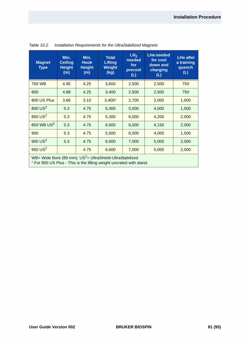
Installation Procedure
Table 10.2. Installation Requirements for the UltraStabilized Magnets
Magnet Type
Min. Ceiling Height
(m)
Min. Hook
Height (m)
Total Lifting Weight
(kg)
LN2needed
for precool
(L)
LHe needed for cool
down and charging
(L)
LHe after a training quench
(L)
750 WB 4.95 4.25 3,600 2,500 2,500 750
800 4.88 4.25 3,400 2,500 2,500 750
800 US Plus 3.66 3.10 3,400* 2,700 2,000 1,000
800 US2 5.3 4.75 5,300 5,000 4,000 1,500
850 US2 5.3 4.75 5,300 6,000 4,200 2,000
850 WB US2 5.3 4.75 6,600 6,000 4,150 2,000
900 5.3 4.75 5,500 6,000 4,000 1,500
900 US2 5.3 4.75 6,600 7,000 5,000 2,000
950 US2 4.75 6,600 7,000 5,000 2,000
WB= Wide Bore (89 mm); US2= UltraShield-UltraStabilized* For 800 US Plus - This is the lifting weight uncrated with stand.
User Guide Version 002 BRUKER BIOSPIN 81 (93)

Installation
82 (93) BRUKER BIOSPIN User Guide Version 002

Figures
1 Introduction 7
2 Safety 11Figure 2.1. Stronger Stray Fields in Vertical Direction than in Horizontal Di-
rection .................................................................................15
3 Equipment 17
4 Magnet Access and Rigging 23Figure 4.1. Unloading the Magnet .........................................................24
5 Ceiling Height Requirements 29Figure 5.1. Minimum Hook Height for Assembly ....................................30Figure 5.2. Helium Transfer Line Insertion .............................................31
6 Magnetic Stray Fields 33Figure 6.1. Magnetic Stray Field Plot 750 WB ........................................35Figure 6.2. Magnetic Stray Field Plot 800 ..............................................36Figure 6.3. Magnetic Stray Field Plot 800 US Plus .................................37Figure 6.4. Magnetic Stray Field Plot 800 US2 ......................................38Figure 6.5. Magnetic Stray Field Plot 850 US2 ......................................39Figure 6.6. Magnetic Stray Field Plot 900 ..............................................40Figure 6.7. Magnetic Stray Field Plot 850WB US2, 900 US2, 950 US2 ..41
7 Floor Plan 43Figure 7.1. Magnet Dimensions .............................................................44Figure 7.2. UltraStabilized Magnet Orientation .......................................45Figure 7.3. Magnet in Pit with Customized Platform ...............................49Figure 7.4. AVANCE 800 US Plus NMR Layout Example .......................53Figure 7.5. AVANCE 900 UltraStabilized NMR Layout Example .............54Figure 7.6. AVANCE 900 US2 NMR Layout Example .............................55
8 Environment and Site Survey Measurement 57
9 Utility Requirements 65Figure 9.1. Main Electrical Power Requirements Flowchart ....................66Figure 9.2. Losses in a Typical Dryer/Filter System Setup .....................70Figure 9.3. Emergency Quench Pipes ...................................................74
10 Installation 77
User Guide Version 002 BRUKER BIOSPIN 83 (93)

Figures
84 (93) BRUKER BIOSPIN User Guide Version 002

Tables
1 Introduction 7Table 1.1. Metric to American Conversion Factors ............................ 9Table 1.2. Temperature Convesion Formulas .................................... 9
2 Safety 11Table 2.1. BGV B11 Standards for Standard Precautions and Users ...
........................................................................................12Table 2.2. BGV B11 Standards Under Special Conditions for Selected
Subgroups 12Table 2.3. Example of Maximum Retention Periods ........................ 13
3 Equipment 17Table 3.1. Refill Time Intervals for UltraStabilized Magnets ............. 18Table 3.2. Spectrometer and Magnet Controls ................................ 19Table 3.3. CryoProbe System ......................................................... 21
4 Magnet Access and Rigging 23Table 4.1. Door Dimensions for Magnet Access .............................. 25Table 4.2. Magnet Transport Weights ............................................. 26
5 Ceiling Height Requirements 29Table 5.1. Minimum Ceiling Height Requirements and Lifting Weights
....................................................................................... 30
6 Magnetic Stray Fields 33Table 6.1. Horizontal Stray Fields (distances are measured in radial di-
rections from magnet center) 33Table 6.2. Vertical Stray Fields (distances are measured in axial direc-
tions from magnet center) 33
7 Floor Plan 43Table 7.1. Dimensions and Weights of NMR Equipment .................. 43Table 7.2. Mass of UltraStabilized Magnets .................................... 44Table 7.3. Maximum Field Strength for NMR Equipment ................. 50Table 7.4. Utility Requirements ....................................................... 52
8 Environment and Site Survey Measurement 57Table 8.1. Recommendations for Static Magnetic Objects .............. 60Table 8.2. Recommendations for Moveable Magnetic Objects ....... 60Table 8.3. Minimum Distances from Sources of DC EMF Interference .
........................................................................................62
User Guide Version 002 BRUKER BIOSPIN 85 (93)

Tables
Table 8.4. List of Most Commonly Studied Nuclei and Corresponding Resonance Frequencies 64
9 Utility Requirements 65Table 9.1. Compressed Gas Requirements .................................... 69Table 9.2. He Gas After a Quench ................................................. 72
10 Installation 77Table 10.1. Magnet Installation Stages ............................................ 77Table 10.2. Installation Requirements for the UltraStabilized Magnets ...
....................................................................................... 81
86 (93) BRUKER BIOSPIN User Guide Version 002

Index
A
Active exhaust.................................................................................................................. 73
Air Conditioning................................................................................................... 71Air conditioning.................................................................................................... 61Air Skates............................................................................................................ 79Airplanes ............................................................................................................. 57Air-skates ............................................................................................................ 25Automatic Sample Changer ................................................................................ 66Automobiles ........................................................................................................ 57AVANCE Cabinet
Dimensions and weight............................................................................. 43AVANCE Cabinets .............................................................................................. 50
B
BACS .................................................................................................................. 68B-CU 05
Dimensions and weight............................................................................. 43BCU05................................................................................................................. 68BCU-05 cooling unit ............................................................................................ 67BMPC.................................................................................................................. 65
Dimensions and weight............................................................................. 43Bruker Monitoring System................................................................................... 66
C
Centrifuges.......................................................................................................... 61Components
Avance ...................................................................................................... 19CryoProbe................................................................................................. 21
Compressors....................................................................................................... 57Constant flow rate ..................................................................................... 69
Construction sites................................................................................................ 57crates .................................................................................................................. 25Croygenic liquids................................................................................................. 14Cryocooling Unit
Dimensions and weight............................................................................. 43Cryogenic liquids
Storage containers.................................................................................... 14Cryogens
Cryogenic gas to liquid volume ratios ....................................................... 13High pressure gas-packs .......................................................................... 14pressure relief valve.................................................................................. 14Refill intervals............................................................................................ 18Safe handling of cryogenic liquids ............................................................ 14
User Guide Version 002 BRUKER BIOSPIN 87 (93)

Index
Safe handling of helium transfer line......................................................... 15Transport dewars ...................................................................................... 14
CryoProbeDimensions and weights of components .................................................. 43
CryoProbe System .............................................................................................. 21
D
D.C. operated trains ............................................................................................ 60DC EMF .............................................................................................................. 61
Guidelines ................................................................................................. 62Digital Lock.......................................................................................................... 61Dimensions & Weights
Magnets .................................................................................................... 44NMR equipment ........................................................................................ 43
Door dimensions ................................................................................................. 25
E
Electric motors .................................................................................................... 61Electromagnetic Interference ........................................................................ 61, 64elevators.............................................................................................................. 61Emergency power ............................................................................................... 66EMF Interference ................................................................................................ 61Exclusion Zone.................................................................................................... 11
F
Fans .................................................................................................................... 57Ferromagnetic objects................................................................................... 12, 59
Moving objects .......................................................................................... 60Field strength
Office furniture .......................................................................................... 50Field strength for NMR Equipment...................................................................... 50Fluctuating fields ................................................................................................. 62Fluxgate magnetometer ...................................................................................... 61
G
Generators .......................................................................................................... 57
H
He fill port ............................................................................................................ 45He manifold ......................................................................................................... 45Heat output.......................................................................................................... 71heat source ......................................................................................................... 45Helium
Helium transfer line ................................................................................... 15Transfer of liquid helium............................................................................ 15
Helium CompressorDimensions and weight............................................................................. 43
Helium pumps ..................................................................................................... 65
88 (93) BRUKER BIOSPIN User Guide Version 002

Index
Helium transfer line ............................................................................................. 29Hold Time............................................................................................................ 18Homogeneity ....................................................................................................... 59Hydraulic lifting system ....................................................................................... 29
J
Joule-Thompson Cooling Unit............................................................................. 17
L
LCD display......................................................................................................... 51Lifting hook.......................................................................................................... 29
M
Machinery............................................................................................................ 57Magnet
Stand......................................................................................................... 58Magnet orientation .............................................................................................. 45Magnet Pits ......................................................................................................... 49Magnet platforms ................................................................................................ 47Magnet Pump Line .............................................................................................. 48Magnet pump line................................................................................................ 45Magnet Slab ........................................................................................................ 46Magnet stand ...................................................................................................... 45Magnetic environment......................................................................................... 59Magnetic Field..................................................................................................... 11
Exclusion Zone ......................................................................................... 11MAS .................................................................................................................... 68Mass spectrometers............................................................................................ 61Medical implants ................................................................................................. 11MicroImaging Cabinet
Dimensions and weight............................................................................. 43Minimum Distances from Sources of Electromagnetic Interference ................... 62Minimum Door Size............................................................................................. 25
N
NitrogenSafe handling during refills........................................................................ 14
NMR EquipmentMaximum field strength............................................................................. 50
NMR workstation................................................................................................. 50
O
Oil Content .......................................................................................................... 68Oxygen level sensors.......................................................................................... 73
P
Passive exhaust .................................................................................................. 73
User Guide Version 002 BRUKER BIOSPIN 89 (93)

Index
PC ....................................................................................................................... 50Pits ...................................................................................................................... 49
Exhaust ............................................................................................... 71, 74Platforms ............................................................................................................. 47Plotter.................................................................................................................. 50power lines .......................................................................................................... 61Pressure relief valve............................................................................................ 14Printer.................................................................................................................. 50Pump-line ............................................................................................................ 17
Q
QuenchHe evaporation.......................................................................................... 72
Quench pipes ...................................................................................................... 73
R
Radio’s ................................................................................................................ 63Refilling
Refill Time Intervals .................................................................................. 18Refill Volume............................................................................................. 18Safe handling of liquid nitrogen................................................................. 14Safe transfer of liquid helium .................................................................... 15
RF interference ................................................................................................... 63Rigging Equipment
Air-Skates ................................................................................................. 27Crane ........................................................................................................ 27Hydraulic lifting system ............................................................................. 29Leveling sheets ......................................................................................... 27Lifting hook................................................................................................ 29Lifting hook or hydraulic lifting system ...................................................... 27Pallet jack and/or forklift ............................................................................ 27
Rigging equipment .............................................................................................. 27
S
SafetyExclusion Zone ......................................................................................... 11Ferromagnetic objects .............................................................................. 12Magnetic field............................................................................................ 11Medically active implants .......................................................................... 11Safe handling of cryogenic liquids ............................................................ 14Safe handling of liquid nitrogen................................................................. 14Ventilation ................................................................................................. 13
Specifications ...................................................................................................... 68Steel reinforced walls .......................................................................................... 60Stray Fields
Horizontal.................................................................................................. 33Stronger stray fields in vertical direction ................................................... 15Vertical ...................................................................................................... 33
Subways.............................................................................................................. 61sunlight................................................................................................................ 45support beams .................................................................................................... 45
90 (93) BRUKER BIOSPIN User Guide Version 002

Index
T
Television broadcasts ......................................................................................... 63Trains .................................................................................................................. 57Trams.................................................................................................................. 61Transformers....................................................................................................... 61Transportation
Air-skates .................................................................................................. 25Door dimensions ....................................................................................... 25Overhead crane ........................................................................................ 24Rigging...................................................................................................... 27Weights ..................................................................................................... 26
U
UltraStabilized Magnets ...................................................................................... 17UPS..................................................................................................................... 65
Dimensions and weight............................................................................. 43
V
Ventilation ........................................................................................................... 13Emergency ventilation............................................................................... 13HVAC systems.......................................................................................... 13When using a magnet pit .......................................................................... 49
Vibrations ............................................................................................................ 57Guidelines ................................................................................................. 58Slab........................................................................................................... 46Sources..................................................................................................... 57
W
Water Content ..................................................................................................... 68Workstation
Dimensions and weight............................................................................. 43
User Guide Version 002 BRUKER BIOSPIN 91 (93)

Index
92 (93) BRUKER BIOSPIN User Guide Version 002

User Guide Version 002 BRUKER BIOSPIN 93 (93)
Notes:

General Safety Considerations for the Installation and
Operation of Superconducting Magnet Systems
Revision 1.1. Last updated: March 29, 2002
Revision: 1.1. Last Updated: March 29, 2002
1

Bruker BioSpin Corporation • 978-667-9580 • www.bruker-biospin.com
List of Contents
Topic Page Introduction 1 Magnetic Field 2 Magnet Zones 5 Safe Handling of Cryogenic Substances 6 Refill of Liquid Nitrogen 10 Refill of Liquid Helium 11 Ventilation 13 Appendix A: Site Survey Checklist
1. Introduction
1.1 Read this first!
Please read it carefully and make it accessible to everybody working with the magnet system.
• A superconducting NMR Magnet System can be operated easily and safely provided the correct procedures are obeyed and certain precautions observed.
• These notes must be read and understood by everyone who comes into contact with a superconducting NMR Magnet System. They are not for the sole information of senior or specialist staff.
• Proper training procedures must be undertaken to educate effectively all people concerned with such equipment with these requirements.
• Since the field of the NMR magnet system is three dimensional, consideration must be given to floors above and below the magnet as well as to the surrounding space at the same level
Revision: 1.1. Last Updated: March 29, 2002
2

1.2 Warning areas
The installation and operation of a superconducting NMR magnet system presents a number of hazards of which all personnel must be aware. It is essential that:
• Areas, in which NMR magnet systems are to be installed and operated, are planned with full consideration for safety.
• Such premises and installations are operated in a safe manner and in accordance with proper procedures.
• Adequate training is given to personnel. • Clear notices are placed and maintained to effectively warn people that they
are entering a hazardous area. • All health and safety procedures are observed. These notes outline aspects of operation and installation which are of particular importance. However, the recommendations given cannot cover every eventuality and if any doubt arises during the operation of the system the user is strongly advised to contact the supplier.
Revision: 1.1. Last Updated: March 29, 2002
3

2. Magnetic Field
2.1 Overview Superconducting NMR magnets pose numerous hazards related to the forces
caused by the strong magnetic fields associated to these magnets. Precautions must be taken to ensure that hazards will not occur due to the effects of a magnetic field on magnetic materials, or on surgical implants. Such effects include, but are not limited to: • Large attractive forces may be exerted on equipment in the proximity of the
NMR magnet system. The force may become large enough to move the equipment uncontrollably towards the NMR magnet system. Small pieces of equipment may therefore become projectiles.
• Large equipment (e.g. gas bottles, power supplies) could cause bodies or limbs to become trapped between the equipment and the magnet.
• The closer a ferromagnetic object gets to the magnet, the larger the force. Also, the larger the equipment mass, the larger the force.
2.2 Shielding Most of the newer NMR magnet systems are actively shielded. The
following must be understood when installing or working with such a shielded magnet: • The active shielding of the superconducting coil reduces the stray magnetic
fields, and therefore its effects. • Nevertheless, the magnetic field gradient is much stronger compared to
non-shielded magnets, hence the distance interval between various stray field contour lines (for instance distance between 5G and 50G) is much smaller, and caution must be taken to avoid bringing ferromagnetic objects close to the magnet.
• In spite of the active shielding, the stray magnetic field directly above and directly below the magnet is very high and the attractive forces on ferromagnetic objects are very strong!
2.3 Electronic, electrical and mechanical medical implants
The following must be understood concerning the effects on electronic, electrical and mechanical medical implants and devices: • The operation of electronic, electrical or mechanical medical implants, such
as cardiac pacemakers, biostimulators, and neurostimulators may be affected or even stopped in the presence of either static or changing magnetic fields.
• Not all pacemakers respond in the same way or at the same field strength if exposed to fields above 5 gauss.
Continued on next page
Revision: 1.1. Last Updated: March 29, 2002
4

2. Magnetic Field, Continued
2.4. Surgical implants and prosthetic devices
The following must be understood concerning the effects on surgical implants and prosthetic devices: • Besides electronic, electrical, and mechanical medical implants, other
medical surgical implants such as aneurysm clips, surgical clips or prostheses, may contain ferromagnetic materials and therefore would be subject to strong attractive forces near to the NMR magnet system. This could result in injury or death.
• Additionally, in the vicinity of rapidly changing fields (e.g. pulsed gradient fields) eddy currents may be induced in the implant, hence resulting in heat generation and possibly create a life-threatening situation.
2.5 Operation of equipment
The operation of equipment may be directly affected by the presence of strong magnetic fields. • Items such as watches, tape recorders and cameras may be magnetized and
irreparably damaged if exposed to fields above 10 gauss. • Information encoded magnetically on credit cards and magnetic tapes may
be irreversibly corrupted. • Electrical transformers may become magnetically saturated in fields above
50 gauss. The safety characteristics of equipment may also be affected.
2.6 Before ramping the magnet to field
Prior to start energizing the magnet system, one must: • Ensure all loose ferromagnetic objects are removed from within 5 gauss
field of the NMR magnet system. • Display magnet warning signs at all points of access to the magnet room. • Display warning signs giving notice of the possible presence of magnetic
fields and of the potential hazards in all areas where the field may exceed 5 gauss.
2.7 After ramping the magnet to field
After energizing the magnet to field, one must: • Not bring ferromagnetic objects into the magnet room. • Use only nonmagnetic cylinders and dewars for storage and transfer of
compressed gas or cryogenic liquids. • Use only non-magnetic equipment to transport cylinders and dewars
Continued on next page
Revision: 1.1. Last Updated: March 29, 2002
5

2. Magnetic Field, Continued
2.8 General safety precautions
To prevent situations as described above to occur, the following precautions are provided as guidelines, and they should be regarded as minimum requirements. • Every magnet site location should be reviewed individually to determine the
precautions needed to be taken against these hazards. • Consideration must be given to floors above and below the magnet as well
as the surrounding space at the same level, since the magnetic field produced by the NMR magnets is three dimensional.
Revision: 1.1. Last Updated: March 29, 2002
6

3. Magnet Zones
3.1 Introduction
The FDA requires that the hazards listed above are prevented by establishing two secure and clearly marked zones, as follows: • The exclusion zone, and • The security zone.
3.2 Exclusion Zone
The following must be understood concerning the exclusion zone: • Definition: The exclusion zone comprises the area (rooms, hallways and so
on) inside the magnets 5-gauss line. Individuals with cardiac or other mechanically active implants must be prevented from entering this area.
• Extension of magnetic field: The magnetic field surrounds the magnet in a three dimensional fashion. Access must be limited and warning given to individuals who are potentially at risk, not only at the same floor as the magnet, but also at the levels above and below the magnet.
• Warning signs: The exclusion zone must be enforced with a combination of warning signs and physical barriers. Figure 1 shows the recommended layout of the warning sign
Figure 1 Warning Sign
3.3 Security Zone
The security zone is usually confined to the room that houses the magnet. The security zone is established to prevent ferromagnetic objects from becoming projectiles. Ferromagnetic objects shall not be allowed inside the security zone.
Revision: 1.1. Last Updated: March 29, 2002
7

4. Safe Handling of Cryogenic Substances
4.1 Overview A superconducting magnet uses two types of cyrogens, liquid helium and
liquid nitrogen. Cryogenic liquids can be handled easily and safely provided certain precautions are obeyed. The recommendations in this section are by no means exhaustive, and when in doubt the user is advised to consult the supplier. • Types of substances: The substances referred to in these recommendations
are nitrogen, helium and air. Contact your cryogen supplier for the appropriate MSDS sheets for these cryogens.
Helium: This is a naturally occurring, inert gas that becomes a liquid at approximately 4K. It is colorless, odorless, non-flammable and non-toxic. In order to remain in a superconducting state the magnet is immersed in a bath of liquid helium. Nitrogen: This is a naturally occurring gas that becomes liquid at approximately 77K. It is also colorless, odorless, non-flammable and non-toxic. It is used to cool the shields, which surround the liquid helium reservoir.
• Cryogen transport dewars: During normal operation, liquid cryogens evaporate and will require replenishment on a regular basis. The cryogens will be delivered to site in transport dewars. It is essential that these cryogen transport dewars are non-magnetic.
• Physical properties: Safe handling of cryogenic liquids requires some knowledge of the physical properties of these liquids, common sense and sufficient understanding to predict the reactions of such liquids under certain physical conditions.
4.2 General safety rules
General safety rules for handling cryogenic substances include, but are not limited to: • Cryogenic liquids remain at a constant temperature by their respective
boiling points and will gradually evaporate, even when kept in insulated storage vessels (dewars)
• Cryogenic liquids must be handled and stored in well ventilated areas. • Passengers should never accompany cryogens in an elevator. There is a
risk of asphyxiation. • The very large increase in volume accompanying the vaporization of the
liquid into gas and the subsequent process of warming up is approximately 740:1 for helium and 680:1 for nitrogen.
Continued on next page
Revision: 1.1. Last Updated: March 29, 2002
8

4. Safe Handling of Cryogenic Substances, Continued
4.3 Cryogen transport dewars
The rules concerning the cryogen dewars used to transport cryogenic liquids include, but are not limited to: • All cryogen dewars transporting cryogenic liquids must not be closed
completely as this would result in a large build up of pressure. This will present an explosion hazard and may lead to large product losses!
• All cryogen transport dewars must be constructed of non-magnetic materials.
4.4 Health hazards
Main health hazard related rules include, but are not limited to: • Evacuate the area immediately in the event of a large spillage • Provide adequate ventilation in the room to avoid oxygen depletion.
Helium can displace air in the upper area of a room and cold nitrogen can displace air in the lower area. Please see the “Ventilation” section for detailed information.
• Do not come in direct contact with cryogenic substances in liquid or vapor form (or as low temperature gases), since they will produce “cold burns” on the skin similar to burns.
• Do not allow insufficiently protected parts of the body to come in contact with non-insulated venting pipes or vessels (see “Ventilation” section), since the body parts will immediately stick to them. This will cause the flesh be torn if the affected body part is removed.
4.5 First aid First aid rules include, but are not limited to:
• If any of the cryogenic liquids come into contact with eyes or skin, immediately flood the affected area with large quantities of cold or tepid water and then apply cold compresses.
• Never use hot water or dry heat. • Medical advice should be sought immediately!
Continued on next page
Revision: 1.1. Last Updated: March 29, 2002
9

4. Safe Handling of Cryogenic Substances, Continued
4.6 Protective clothing
Protective clothing rules include, but are not limited to: • Protective clothing must be worn mainly to avoid cold burns. Therefore dry
leather or cryogenic gloves must be worn when handling or working with cryogenic liquids.
• Gloves must be loose fitting so that they can be removed easily in case of liquid spillage.
• Goggles must be worn to protect the eyes. • Any metallic objects (e.g. jewelry) should not be worn on those parts of the
body, which may come into contact with the liquid.
4.7 Others Other rules of handling cryogens include, but are not limited to:
• Handle the liquids carefully at all times. Boiling and splashing will always occur when filling a warm container.
• Beware of liquid splashing and rapid flash off of cryogens when immersing equipment at ambient temperature into the liquid cryogens. This operation must be carried out very slowly.
• When inserting open ended pipes into the liquid, never allow open ended pipes to point directly towards any person
• Use only metal or Teflon tubing connected by flexible metal or Teflon hose for transferring liquid nitrogen. Use only gum rubber or Teflon tubing.
• Do not use tygon or plastic tubing. They may split or shatter when cooled by the liquid flowing through it and could cause injury to personnel.
4.8 Smoking Please obey the following basic rules concerning smoking:
• Do not smoke in any rooms in which cryogenic liquids are being handled • Designate all rooms in which cryogenic liquids are being handled as “No
Smoking” areas, using appropriate signs Additional facts and precautions: • While nitrogen and helium do not support combustion, their extreme cold
dewar causes oxygen from the air to condense on the dewar surfaces, which may increase the oxygen concentration locally.
• There is a particular fire danger if the cold surfaces are covered with oil or grease, which are combustible. Self-ignition could occur!
Continued on next page
Revision: 1.1. Last Updated: March 29, 2002
10

4. Safe Handling of Cryogenic Substances, Continued
4.9 Properties of cryogenic substances
Properties Nitrogen Helium
Molecular weight 28 4
Normal boiling point [oC] [oK]
-196 77
-269 4.2
Approximate expansion ration (volume of gas at 15’C and atmospheric pressure produced by unit volume of liquid at normal boiling point).
680 740
Density of liquid at normal boiling point [kg m-3]
810 125
Color (liquid) none none
Color (gas) none none
Odor (gas) none none
Toxicity very low very low
Explosion hazard with combustible material
no no
Pressure rupture if liquid or cold gas is trapped.
yes yes
Fire hazard: combustible no no
Fire hazard: promotes ignition directly no no
Fire hazard: liquefies oxygen and promotes ignition
no no
Revision: 1.1. Last Updated: March 29, 2002
11

5. Refill of Liquid Nitrogen
5.1 Read this first!
Please read this carefully and make it accessible to anybody working with the magnet system. • A shielded superconducting NMR Magnet System can be operated easily
and safely provided the correct procedures are obeyed and certain precautions observed.
• The recommendations in this section cannot cover every eventuality and if any doubt arises during the operation of the system, the user is strongly advised to contact the supplier.
5.2 Condensing oxygen
Minimize contact with air. Be aware of the following facts and precautions, contact with air occurs: • Since liquid nitrogen is colder than liquid oxygen, the oxygen in the air will
condense out. • If this happens for a period of time, the oxygen concentration in the liquid
nitrogen may become so high that it becomes as dangerous as handling liquid oxygen. This applies particularly to wide necked dewars due to the large surface area.
• Therefore, ensure that contact with air is kept to a minimum.
5.3 Nitrogen flow system
A pressure relief valve is provided for the nitrogen vessel to ensure that at least the rear neck tube cannot be blocked by the ingress of air or moisture. This valve shall be mounted at all times even when the vessel is being refilled.
5.4 Refill of liquid nitrogen
Other general rules include, but are not limited to: • Do not allow liquid nitrogen to spill onto the room temperature bore closure
flanges when the refilling the nitrogen vessel • Place gum rubber tubes or Teflon tubes on the nitrogen neck tubes during
refill! • Stop the transfer immediately when the vessel is full. Failure to observe
this can lead to the freezing of the o-rings and a subsequent vacuum loss of the magnet cryostat.
Revision: 1.1. Last Updated: March 29, 2002
12

6. Refill of Liquid Helium
6.1 Read this first!
Please read this carefully and make it accessible to anybody working with the magnet system. • A shielded superconducting NMR Magnet System can be operated easily
and safely provided the correct procedures are obeyed and certain precautions observed.
The recommendations in this section cannot cover every eventuality and if any doubt arises during the operation of the system, the user is strongly advised to contact the supplier.
6.2 General rules when handling liquid helium
Be aware of these general rules including, but not limited to: • Liquid helium is the coldest of all cryogenic liquids. • Liquid helium will condense and solidify any other gas (air) coming into
contact with it. • Liquid helium must be kept in specially designed storage or transport
dewars. • Dewars should have a one way valve fitted on the helium neck at all times,
in order to avoid air entering the neck and plugging it with ice. • Only vacuum insulated pipes should be used for liquid helium transfer.
Breakdown of the insulation may give rise to the condensation of oxygen.
6.3 The helium vessel
The superconducting NMR magnets contain an inner vessel with liquid helium. • The helium vessel should be checked weekly for boil-off and helium level. • Use a helium flow meter or a helium gas counter! • A one way valve is supplied to be mounted on the helium manifold to
ensure that the helium neck tubes cannot be locked by the ingress of air or moisture. This valve should be mounted at all times except during a helium transfer
Continued on next page
Revision: 1.1. Last Updated: March 29, 2002
13

6. Refill of Liquid Helium, Continued
6.4 Refill of liquid helium
Please follow the following instructions concerning the refill of NMR magnets with liquid helium: • Refill the helium vessel within the specified hold time period and certainly
before the level falls below the allowed minimum level listed in the magnet manual.
• Important Note: Transfer of liquid helium can be done easily and safely, provided:
the handling of the helium transfer line is correct, the helium transfer line is not damaged, and the transfer pressure does not exceed 2 psi.
• Never insert a warm helium transfer line into the cryostat, since the warm helium gas could lead to a quench of the magnet!
• Always allow the helium transfer line to cool down to helium temperature before inserting it into the right helium neck tube. You should see liquid helium leaving of the short end transfer lines for a few moments, before inserting it into the right helium neck tube.
6.5 Rapid Helium transfer
Do not remove the nitrogen security flow system during any transfer liquid helium! During a rapid transfer of liquid helium, super cooling of the liquid nitrogen occurs. This can lead to the following: • Decrease of static boil off to zero, and producing a negative pressure in the
nitrogen vessel • Transfer of air or moisture that can be sucked into the necks of the vessel,
and which would solidify and create ice blockages.
Revision: 1.1. Last Updated: March 29, 2002
14

7. Ventilation
7.1 General safety rules concerning ventilation
General safety rules concerning ventilation include, but are no limited to: • Cryogenic liquids, even when kept in insulated storage dewars, remain at a
constant temperature by their respective boiling points and will gradually evaporate. These dewars must always be allowed to vent or dangerous pressure buildup will occur.
• Cryogenic liquids must be handled and stored in well ventilated areas. • The very large increase in volume accompanying the vaporization of the
liquid into gas and the subsequent process of warming up is approximately 740:1 for helium and 680:1 for nitrogen.
7.2 Ventilation during normal operation
Superconducting magnets use liquid nitrogen and liquid helium as cooling agents, and a boil-off of liquid cryogens is expected during the normal operation of the magnet system, as follows: • Normal boil-off of liquids contained in the magnet based on the given boil-
off specifications • Boil-off of cryogens during the regular refills with liquid nitrogen and
liquid helium. The gases are nontoxic and completely harmless as long as adequate ventilation is provided to avoid suffocation. Rules for ventilation during normal operation include but are not limited to: • The NMR magnet system should never be in an airtight room. The magnet
location should be selected such that the door and the ventilation can be easily reached from all places in the room.
• Room layout, ceiling clearance and magnet height should be such that an easy transfer of liquid nitrogen and helium is possible. This will considerably reduce the risk of accidents.
7.3 Emergency Ventilation during a quench and during magnet installation
A separate emergency ventilation system should be provided to prevent oxygen depletion in case of a quench or during the magnet installation. During a quench, an extremely large quantity of helium gas (i.e. 1,500 to 21,000 ft3 depending on the magnet type) are produced within a short time During the installation and cooling of superconducting magnets, under certain conditions, large volumes of nitrogen or helium gases may be generated.
Continued on next page
Revision: 1.1. Last Updated: March 29, 2002
15

7. Ventilation, Continued
7.3 Emergency Ventilation during a quench and during magnet installation (continued)
Although these gases are inert, if generated in large enough quantities, they can create dangerous circumstances if they displace the oxygen in the room. The table below illustrates this with examples. Notes: • The values below are approximate may not reflect actual conditions. They
are to be used for example only. • Pre-cool times vary. • Quench times are generally longer. • Please consult with Bruker BioSpin for values associated to your NMR
magnet system
Magnet type N2 gas liberated during
pre-cool
Time to liberate N2 gas during
pre-cool
He gas liberated during
Cooling and filling
Time to evolve He gas during cooling and
filling
He gas liberated during a “quench”
Time to liberate He gas
during a “quench”
UltraShield 300/54
3,600 ft3 4 hours 5,300 ft3 3 hours 1,400 ft3 0.5 minute
UltraShield 700/54
31,500 ft3 24 hours 30,000 ft3 6 hours 11,800 ft3 1 minute
7.4 Emergency exhaust
There are various types of emergency exhaust that can be implemented to avoid oxygen depletion during a quench or during the installation of the magnet system. These include, but are not limited to: • Active exhaust: This solution is based on a motorized fan, vents, and
exhaust duct pipe that is not connected to the magnet itself. The exhaust should be activated both automatically by an O2 sensor, as well as manually by a switch in the room. The latter is needed during magnet installation and regular refills to prevent cryogen build-up in the room by evacuating them faster than the regular HVAC system.
• Passive exhaust: This solution is based on louvers in the ceiling that open by the gas due to the overpressure of helium gas during a quench.
Continued on next page
Revision: 1.1. Last Updated: March 29, 2002
16

Revision: 1.1. Last Updated: March 29, 2002
17
7. Ventilation, Continued
7.4 Emergency exhaust (continued)
• Quench pipe: This solution is based on a pipe connected directly to the magnet, which is then routed to the outside of the building. It is important to note the following:
Ideally, the helium exhaust from the magnet should be vented directly to the outside of the building in case a quench occurs. The ducting to the outside of the building should be of large enough diameter to avoid excessive pressure build up due to the flow impedance of the duct. The location of the exit end of the exhaust duct must not allow unrestricted access to anyone other than service personnel; in addition the exit opening should be protected from the ingress of rain, snow or any debris which could block the system. It is also essential to ensure that any gas which vents from the exhaust duct cannot be drawn in to any air conditioning or ventilation system intakes. The location of duct’s exit should be carefully sited to prevent this from happening in all atmospheric conditions and winds. Insulation of accessible exhaust piping should also be provided to prevent cold burns during a quench.
• Exhaust for magnet pits: Special attention to ventilation and emergency exhaust must be given when magnets are placed inside pits. Magnet pits are confined spaces with a possibility of increased risk of oxygen depletion if appropriate exhaust measures are not taken.
Nitrogen is heavier than the air and starts filling the pit from the bottom during the magnet pre-cool or regular nitrogen fills It is essential to provide a low exhaust system down inside the pit to efficiently evacuate the nitrogen gas and prevent oxygen depletion
7.5 Oxygen monitor and level sensors
An oxygen monitor is required inside the magnet room. The following sensors should be provided: • Above the magnet: One oxygen level sensor above the magnet, to detect
low oxygen levels due mainly to He gas • Close to floor: One oxygen level sensor 1’ off the floor of the magnet room • Down in the pit: One additional oxygen level sensor 1’ off the bottom of
the pit, in case the magnet is located inside a pit.

Avance UltraStabilized Site Planning Checklist Version 3.0, January 2006
1
AVANCE™ UltraStabilized™ PRE-INSTALLATION SITING REVIEW, Rev. 3.0, January 2006 CUSTOMER INFORMATION Institution:
Users Name/Title:
E-mail Phone Name of person
filling out this form:
Date:
Magnet Type Accessories
750 MHz WB MAS 800 MHz Solids 800 US2 MHz BCU-05 Cooling Unit 900 MHz BACS Sample Changer, NMR Case
Other ______ CryoProbe u Imaging
Other _______________
Expected Date of Delivery and Start of Installation:

Avance UltraStabilized Site Planning Checklist Version 3.0, January 2006
2
NMR SYSTEM AND LARGE PACKAGES DELIVERY ADDRESS:
End Users Name: Phone: E-mail:
Facility manager: Phone:
E-mail:
Receiving hours of operation: FEDEX , UPS, MAIL – REGULAR PACKAGES DELIVERY ADDRESS
Receiving hours of operation:

Avance UltraStabilized Site Planning Checklist Version 3.0, January 2006
3
1. ACCESS AND RIGGING
Delivery Area and Off-loading
• Is there sufficient space in the driveway or parking for the overhead crane and for the delivery flat-bed truck?
• Is there sufficient leveled area for uncrating the magnet crate?
• Distance of reach for the crane, estimated crane size needed
• Is access to the NMR room being done with a crane through hatch in the
roof?
• Is the NMR room at a different elevation relative to the delivery area? If
yes, explain how is the access to the NMR room being done
• Is access to the NMR room requiring air-skates?
Continued on next page

Avance UltraStabilized Site Planning Checklist Version 3.0, January 2006
4
ACCESS AND RIGGING, Continued
Access to the NMR Room
• Is there a suitable leveled slab (pad) in front of the access doors for positioning the magnet on air-skates? Is the slab capable to handle the size and weight of the magnet?
• Are masonite sheets needed to correct imperfections and protect flooring?
• Clearances along the access path from the delivery area to the NMR room
• Load bearing capacity along the access path
• Access of fork-truck or palette-jack
Rigging inside the lab for magnet lifting
• Fixed lifting hook in the ceiling/beam: Hook height (floor to bottom of ceiling hook)
Max. lifting load
Height clearance from floor to hook of hoist system
• Hydraulic lift system with I-beam
Height clearance for setting-up the hydraulic lift system:
• Bruker special hydraulic lift system:

Avance UltraStabilized Site Planning Checklist Version 3.0, January 2006
5
2. CEILING HEIGHT REQUIREMENTS
Height for lifting magnet
• Ceiling height from the floor to underside of ceiling: • Ceiling hook height if applicable: • Footprint of ceiling above magnet with max. height clearance:
Height for magnet energization
• Final ceiling height above magnet measured from the floor: • Type of energizing rods (standard or bendable):
Height above He dewars
• Ceiling height above He transport dewar measured from the floor:
Obstructions above and below magnet
•

Avance UltraStabilized Site Planning Checklist Version 3.0, January 2006
6
3. FLOOR PLAN
Stray Fields • Is the 5G line completely enclosed within the NMR room?
• Is the magnet He cooling pump unit as well as the He compressor for the
CryoProbe going to be located outside the 5G line?
Magnet Pit • Footprint of the magnet pit:
• Depth of the pit: • Reinforcement in the slab and walls of the pit:
Magnet Slab • Is the magnet going to be placed on its own slab, isolated from the rest of
the floor of the NMR room?
• Is the isolation preventing the transmission of both vertical and horizontal vibrations? How is the isolation being done?
• Size of the magnet slab: • Type of reinforcement used for the magnet slab: • Type of reinforcement is used for the main floor of the NMR room:
Magnet Platform
• Material: • Overall footprint of the magnet platform: • Is the magnet platform going to be supported from the outside the magnet
slab?
• Are the support posts going to interfere with the magnet, with the access to the magnet, or with the installation of the CryoProbe?
• Diameter of the circular opening: • Height of the platform deck: • Border around the opening: • Removable section to allow for magnet access:
Continued on next page

Avance UltraStabilized Site Planning Checklist Version 3.0, January 2006
7
3. FLOOR PLAN, Continued
Magnet Orientation
• Stairs of the platform: • Magnet Manifold: • He fill port, He supply dewars • Front of magnet stand, CryoProbe, Shims:
Trenches • Are there any trenches? If yes, please describe the scope and provide
dimensions.
Magnet Pump Line – Route to the Pump Unit
• Route of magnet pump line:
NMR Equipment
• UPS, Pump unit, BMPC, Avance cabinet, workstation: • BCU-05:
CryoProbe Siting
• CryoCooling unit: • Transfer lines from CryoProbe to the CryoCooling unit: • Buck-booster transformer: • He compressor: • Water chiller, and water quality: • He gas cylinder (high purity): • Back-up gas cylinder:
Continued on next page

Avance UltraStabilized Site Planning Checklist Version 3.0, January 2006
8
3. FLOOR PLAN, Continued
Floor plan drawing

Avance UltraStabilized Site Planning Checklist Version 3.0, January 2006
9
4. ENVIRONMENT AND SITE SURVEY MEASUREMENTS
Vibrations • Measurements on the magnet slab and outside the slab
• Sources of vibrations: • Expected vertical accelerations on the magnet with the standard vibration
isolation units (inflatable Firestone tires) activated:
Magnetic Environment
• Is there any iron mass including reinforcement in the walls and floor that is present within an area of 12’ (4 m) radius from the magnet center (MC)?
• Are there any steel beams, columns radiators, plumbing pipes, metal tables,
metal doors, filing cabinets, or other massive static steel objects within an area of 14’ (4.3 m) radius from MC?
• Is there any moving iron mass present within an area of 20’ (6 m) from
MC?
• Are there any moving steel objects as large metal doors, hand trolley, or any large steel parts of rotatory machines and other mechanical equipment present within an area of 30’ (10 m) radius from MC?
• Are there any elevators, trucks, cars, fork-lifts and alike being operated
within 45’ (14 m) distance from MC?
• Are there any trains passing within 120’ (37 m) distance from MC?
Continued on next page

Avance UltraStabilized Site Planning Checklist Version 3.0, January 2006
10
4. ENVIRONMENT AND SITE SURVEY MEASUREMENTS, Continued
EMF Interference
• DC: a) Are there any trains, subways, trams or associated DC power lines present within 600’ (~ 190 m) distance from MC? b) Are there any mass spectrometers located into the room or adjacent spaces?
DC EMF measurements
• AC: Are there any large transformers, AC power lines, or powerful lighting in close proximity to the magnet location?
AC 60Hz EMF measurements
• RF: a) Are there any known TV / Radio Stations, Cellular Phone Towers and Antennas, or other possible sources of RF in the building or within a radius of 5 miles (~8 km)? b) Are there any other NMR or MRI systems operating at the same resonance frequency?
Details on possible RF sources RF analysis

Avance UltraStabilized Site Planning Checklist Version 3.0, January 2006
11
5. UTILITY REQUIREMENTS
Electrical Power, phone line commun.
• Main Power Disconnect Box: 208V/60A single phase
• Additional 208V single phase NEMA L6-30R (1), L6-20R (2)
• 110V outlets:
• Power for the CryoCooling. Would a UPS cover it?
• Power for the He compressor. Is it on emergency power?
• Power for BCU-05:
• Power for the workstation. Would a UPS cover it?
• Back-up emergency generator:
• Fax / modem dedicated line:
(Refer to the Site Planning Manual for non-North American requirements)
Compressed gas
• Air:
• Nitrogen:
• Pressure • Flow: • N2 separator:
Water • Chiller and quality specs for water (CryoProbe with indoor water-cooled He
compressor
Continued on next page

Avance UltraStabilized Site Planning Checklist Version 3.0, January 2006
12
5. UTILITY REQUIREMENTS, Continued
Lighting • Types of lights:
• Are all lights at least 10’ (3 m) away from the magnet center?
• Are there any spot lights on the magnet?
HVAC • Is there an HVAC system dedicated to the NMR room?
• Is the air flow into the NMR room continuous:
• How is the air temperature control being done? Are there any control
switches operating the HVAC that may cause oscillations in flow/temperature:
• Is the HVAC exchanging a large air-volume and are there any air drafts
inside the NMR room associated to it?
• Is there noticeable noise (acoustical vibrations) produced by the HVAC system?
• Is there ductwork present in the room or adjacent space, what is the material
that is made out of, and does it show signs of vibrations?
• Location of air supply diffusers and return (exhaust) grills
• Is there any air draft towards magnet or console?
• Are there any windows in the NMR room and any direct sunlight in the space?
• What is expected temperature stability inside the NMR room, in the area of
the magnet and console?
Continued on next page

Avance UltraStabilized Site Planning Checklist Version 3.0, January 2006
13
5. UTILITY REQUIREMENTS, Continued
Emergency Gas Exhaust, and misc. utilities
• Space volume available in the NMR room (approx.): • Volume of He gas after a quench: • Calculated height of He gas cloud (measured from the floor) after a quench: • Type of emergency exhaust:
Passive (louver): Active (fan) and activation: Quench pipe:
• Ventilation required during the installation (cooling of magnet) and follow-
up cryogen fills: • Make-up air for emergencies: • Location of smoke detectors: • Location and type of sprinkler heads” • O2 sensors - in the upper part as well as lower part of the room?
Location Automatic switch-on of the emergency exhaust Heat sensors wired-in to the O2 sensors
• Manual override button for emergency exhaust / conditions:
Cryogens • Cryogen storage room:
• Cryogens needed for the installation: Liquid cryogens: LN2 and LHe Gases
• What is the access path for cryogen supply dewars, and are all openings large enough for these dewars. Is the access path for the cryogen dewars intrude into the 5G areas of adjacent magnets?
• High purity He gas for the CryoProbe: • Back-up N2 or air for the CryoProbe (assumes the sample protection is
included with the order):

Avance UltraStabilized Site Planning Checklist Version 3.0, January 2006
14
6. DECLARATION BY THE INSTALLATION CONTACT
Declaration by the Installation Contact
I acknowledge receipt of the Bruker BioSpin document entitled “General Safety Considerations for the Operation and Installation of Superconducting Magnets”.
I confirm that, to the best of my knowledge and belief, the information that I have given in sections 1 – 5 of this Site Planning Checklist is accurate.
For safety reasons I agree that the Bruker BioSpin installation engineer will not be allowed to work alone at any time, and his work will be suspended if left unaccompanied. I understand that after the magnet has been installed, for safety reasons, routine maintenance tasks involving transfer of cryogenic liquids must be performed by personnel formally trained to do so.
Signature of Installation Contact: …………………………..
Name of Installation Contact: …………………………..
Date: …………………………..

Avance UltraStabilized Site Planning Checklist Version 3.0, January 2006
15
7. DECLARATION BY THE SAFETY OFFICER
Safety Officer Your Site Safety Officer must complete this section.
Magnet Lab Safety Officer’s name ………………………… Magnet Lab Safety Officer’s telephone number ………………………… Magnet Lab Safety Officer’s e-mail address ………………………… Safety Hazards: Please describe any existing hazards present on your site that our Installation Engineer should be aware of e.g. chemicals/acids, laser equipment, radioactive sources, other magnetic devices, etc.
.............................................................................................................................
............………………………………please continue on separate sheets if necessary
Induction Training: If you feel that our Installation Engineer will require Induction Training to prepare him for the hazards on your site, please indicate the type and duration of such training:
............................................................................................................................. Cryogen Storage: Is there a facility for the safe storage of cryogens and gas cylinders on your site?
Yes If no, briefly explain………………………………………… No ……………………………………………………………………….
Cryogen Transportation: What arrangements do you have to safely transport cryogen dewars from the delivery point to their final point of use? …………………………………………………………………………………. …………………………………………………………………………………. Note: Users are reminded that personnel must never accompany cryogen dewars in elevators. O2 Monitor: Will an oxygen level monitoring device be available at the magnet’s location?
Yes If no, briefly explain………………………………………… No ……………………………………………………………………….
Lifting Equipment: Are records/certificates available to confirm that the lifting equipment to be used to move and assemble the magnet is in sound condition and subject to regular examinations?
Yes If no, briefly explain………………………………………… No ……………………………………………………………………….
Continued on next page

Avance UltraStabilized Site Planning Checklist Version 3.0, January 2006
16
7. DECLARATION BY THE SAFETY OFFICER, Continued
Declaration by the Safety Officer
I acknowledge receipt of the Bruker BioSpin document entitled “General Safety Considerations for the Operation and Installation of Superconducting Magnets”.
I confirm that, to the best of my knowledge and belief, the safety information that I have given in this section 7 of the Site Planning Checklist is accurate. For safety reasons I agree that the Bruker BioSpin installation engineer will not be allowed to work alone at any time, and his work will be suspended if left unaccompanied. I understand that after the magnet has been installed, for safety reasons, routine maintenance tasks involving transfer of cryogenic liquids must be performed by personnel formally trained to do so. Signature of Site Safety Officer: ………………………….. Date: ……………...................... Name of Site Safety Officer: ………………………….. Telephone: ………………………….. Fax: ………………………….. E-mail: …………………………..