
Site Exploration and Characterization; Part I
41
1 Site Exploration and Characterization; Part I
Transcript of Site Exploration and Characterization; Part I

1
Site Exploration and Characterization; Part I

2
The Context for
Geotechnical Exploration
What you know….
Planned site development
Proposed structure information
Surface and subsurface data
What you want to know…
Geotechnical Design Recommendations
Preliminary
Final

3
What is Site Characterization?
One working definition:
“The process by which a [geo-professional]
identifies and describes both the surface and the
subsurface materials and conditions at a project
site relative to an established design objective.”
Or:
“A project site so described.”

Why Do It?
“Subsurface material
properties cannot be
specified; they must be
deduced through
exploration.”
Charles Dowding (1979)

5
Some Common Objectives
Identify & describe pertinent surface
conditions
Determine location and thickness of soil and
rock strata (subsurface soil profile)
Determine location of groundwater table
Recover samples for laboratory testing
Conduct lab and/or field testing
Identify special problems and concerns

Geotechnical Project Sequence
Site Research
Field Reconnaissance
Field Exploration
Laboratory Investigations
Geotechnical Interpretations, Analysis
Report of Exploration

7
Non-Intrusive Exploration

8
Site Research (Published Information)
Development Plans
Construction Plans
Site Location Maps
Topographic Maps
Aerial Photographs
Geologic Maps
Soil Survey Maps

9
Geologic
Maps

10
Field Reconnaissance
Observation of Surface Conditions
Accessibility
Traffic Control
Surface Drainage
Geologic Features
Vegetation
Slopes
Water

11
Geophysical Methods
Electrical Resistivity
Surveys
Geophysical Logging

12
Example Non-Intrusive Exploration

13
Example Non-Intrusive Exploration

14
Intrusive (Field) Exploration

15
Reference: Braja M. Das, Principles of Geotechnical Engineering, 6th Edition
Preliminaries: How Many Borings
& How Deep?
“No hard-and-fast rule exists for
determining the number of borings or
the depth to which borings are to be
advanced.”

16
Conventional Wisdom :
The number (density) of borings will increase:
• As soil variability increases
• As the loads increase
• For more critical/significant structures
Rules of Thumb :
Soft Soils (<10 bpf) - Space 100’ to 200’
As soils become harder, spacing may be
increased up to 500’
Preliminaries:
How Many Borings?

17
Preliminaries:
How Many Borings?
Source: Sowers 1979
Structure or
Project
Subsurface
Variability
Spacing of Borings (ft)
Highway
Subgrade
Irregular 100-1000 (200, typical)
Average 200-2000 (500, typical)
Uniform 400-4000 (1000, typical)
Multistory
Building
Irregular 25-75
Average 50-150
Uniform 100-300
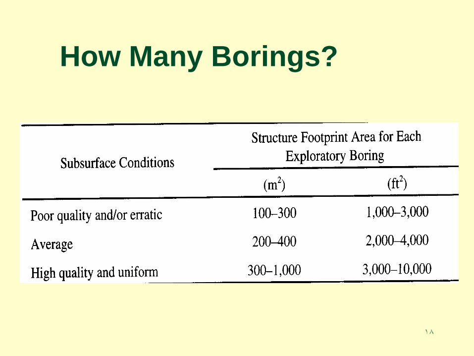
18
How Many Borings?

19
How Deep?

20
Preliminaries:
How Deep (Bridges)?
Boring depth is governed by various factors, including:
Foundation type
Foundation load
Lowering of grade line at underpass?
Channel relocation, widening, dredging?
Scour?
Rules of Thumb
Generally speaking, 50’- 80’ is reasonable
Local experience is helpful
Look at nearby structures if available
If no experience or other info available, plan for long first hole, then adjust.

21
Boring depth is governed by various factors, including:
Wall type (Fill vs. Cut)
Lowering of grade line at wall?
Scour?
Rules of Thumb :
Fill Walls: Depth = Wall Height +/-
Soil Nailed Walls: Depth = Through Nailed Area, plus 10’
Drilled Shaft Walls: Depth = Through Exposed Wall Height, plus 150% of Wall Height
Preliminaries:
How Deep (Retaining Walls)?

22
Types of Drilling Equipment

23
Truck-Mounted Drill Rig
Typical Equipment
Used for
Geotechnical
Drilling
Truck Mounted
Drill Rig &
Support Truck
(Water Tank)

24
Field Drilling and Sampling
Air or Mud Rotary
Drilling

25
Angle Drilling
Assess geologic
features (dip, strike,
joints, etc.)
Foundation testing for
bridge abutments.

26
Confined Access/ Interior
Drilling
Limited Access Drill Rigs are small in size, but have the torque of many full size truck rigs.
Capability, boring depths, size, etc. vary
Esp. useful for remedial sampling

27
Exploration for
abutments,
bridges,
docks, etc.
Offshore Drilling/ Barge Rig

28
Congested Busy Sites
Reliable underground
utility locate is critical
Traffic control is a must
Large percentage of effort
is in the planning
Special ordinances/
regulations may apply

29
Soil & Rock
Drilling & Sampling

30
Drilling vs. Sampling
Think in terms
of a continuum
Many methods
to advance an
exploratory shaft
You get what
you pay for
Drilling ▼
Sampling▼
Effort LOW HIGH
Cost LOW HIGH
Time LOW HIGH
Data LOW HIGH
Quality LOW HIGH
Samples
NO
TH
ING
CU
TT
ING
S
CU
TT
ING
S A
T
DE
PT
H
CU
TT
ING
S W
/
PE
NE
TR
AT
ION
TE
ST
INT
ER
MIT
TE
NT
DIS
TU
RB
ED
INT
ER
MIT
TE
NT
UN
DIS
TU
RB
ED
CO
NT
INU
OU
S/
UN
DIS
TU
RB
ED

31
Drilling vs. Sampling
Drilling – “Just” a hole… no sample
Disturbed Sampling
“…Estimating the nature of the formation
from the cuttings is like identifying the cow
from the hamburgers.” G.F. Sowers
Undisturbed Sampling Retrieve a continuous core
Applicable to both soil and rock

32
Bit at the end of drill rod
rotated and advanced
Soil/rock cuttings removed by
circulating drilling fluid
Common drilling fluid;
bentonite in water with slurry
density 68-72pcf
Air may be used as drilling
fluid
Drilling:
Rotary Bit

33
Drilling:
Continuous Flight Auger

34
Casing with outer spiral
Inner rod with plug/or pilot
assembly
For sampling, remove pilot
assembly and insert sampler
Typically 5ft sections, keyed,
box & pin connections
Maximum depth 60-150ft
Drilling & Sampling
Hollow Stem Auger

35
Drilling & Sampling
Hollow Stem Auger

36
Double-tube core
barrel is typical
Diamond or tungsten-
carbide tooth bit
Size of core samples
varies (NX, NQ, HQ,
etc.)
Drilling & Sampling
Rock Coring

37
Core recovery percentage
Rock Quality Designation
(RQD)
• Defines the fraction of solid core
recovered greater than 4 inches
in length
• Calculated as the ratio of the
sum of length of core fragments
greater than 4 inches to the total
drilled footage per run,
expressed as a percentage
Drilling & Sampling
Rock Core Quality

38
Drilling & Sampling
Shelby Tube Sampler
Suitable for SOIL
Thin-wall Steel Tubes
3.0" OD, 2.875" ID, 30.0" long,
7.2 lbs

39
Ground Water

40
Groundwater Monitoring
Groundwater level must be determined during geotechnical exploration
Measure at time of drilling and later (24 hrs, 1 week, etc.)
Can be accomplished by leaving selected soil borings open
Or, install a piezometer

41
Ground Water
Piezometers
Monitor Wells &
Sampling
Permeability Tests


