SISTM1040-262D-LRT-B User Guide Rev A May 11, 2016
125
SISTM1040-262D-LRT-B Hardened Managed Ethernet Switch User Guide PN 33617 Rev. A Version 1.3 May 2015
Transcript of SISTM1040-262D-LRT-B User Guide Rev A May 11, 2016
SISTM1040-262D-LRT-B
Hardened Managed
Ethernet Switch
User Guide
PN 33617 Rev. A Version 1.3 May 2015

Transition Networks SISTM1040-262D-LRT-B User Guide
33617 Rev. A www.transition.com Page 1 of 125
Trademarks
All trademarks and registered trademarks are the property of their respective owners.
Copyright Notice/Restrictions
Copyright © 2015 Transition Networks. All rights reserved.No part of this work may be
reproduced or used in any form or by any means (graphic, electronic or mechanical) without
written permission from Transition Networks. The information contained herein is confidential
property of Transition Networks, Inc. The use, copying, transfer or disclosure of such
information is prohibited except by express written agreement with Transition Networks, Inc.
Printed in the U.S.A.
Contact Information
Transition Networks
10900 Red Circle Drive
Minnetonka, MN 55343 USA
Tel: 952- 941-7600 or 1-800-526-9267
Fax: 952-941-2322
SISTM1040-262D-LRT-B Industrial Managed Ethernet Switch User Guide PN 33617 Rev. A
Revision History
Rev Date Description
A 6/1/15 Initial release for SISTM1040-262D-LRT-B at v 1.3.

Transition Networks SISTM1040-262D-LRT-B User Guide
33617 Rev. A www.transition.com Page 2 of 125
Table of Contents 1. Getting to Know Your Switch ............................................................................................ 5
1.1 Introduction ............................................................................................................. 5
1.2 Software Features ................................................................................................... 5
1.3 Hardware Features ................................................................................................. 5
1.4 Packing List ................................................................................................................. 6
1.5 Optional Accessories ................................................................................................... 6
2.1 Installing the Switch on DIN-Rails ........................................................................... 7
2.1.1 Mount on DIN-Rails ............................................................................................ 7
2.2 Wall Mounting Installation ....................................................................................... 8
2.2.1 Mount on Wall ..................................................................................................... 8
3. Hardware Overview ............................................................................................................ 9
3.1 Front Panel ............................................................................................................. 9
3.2 Front Panel LEDs .................................................................................................. 10
3.3 Top Panel .............................................................................................................. 11
3.4 Rear Panel ............................................................................................................ 11
4. Cables ............................................................................................................................... 12
4.1 Ethernet Cables .................................................................................................... 12
4.1.1 10/100/100BASE-TX/10BASE-T Pin Assignments ............................................ 12
4.2 SFPs ..................................................................................................................... 14
4.3 Console Cable ...................................................................................................... 14
5. WEB Management ............................................................................................................ 15
5.1 Configuration by Web Browser .............................................................................. 15
5.1.1 About Web-based Management ....................................................................... 15
5.1.2 System Information ........................................................................................... 17
5.1.3 Front Panel ....................................................................................................... 17
5.1.4 Basic setting ..................................................................................................... 18
5.1.4.1 Switch Setting .......................................................................................... 18
5.1.4.2 Admin Password ...................................................................................... 19
5.1.4.3 IP Setting .................................................................................................. 20
5.1.4.4 IPv6 Setting .............................................................................................. 21
5.1.4.5 SNTP (Time) ............................................................................................ 22
5.1.4.6 LLDP ........................................................................................................ 24
5.1.4.7 Auto Provision .......................................................................................... 25
5.1.4.8 Backup & Restore .................................................................................... 26
5.1.4.9 Upgrade Firmware ................................................................................... 27

Transition Networks SISTM1040-262D-LRT-B User Guide
33617 Rev. A www.transition.com Page 3 of 125
5.1.5 DHCP Server .................................................................................................... 28
5.1.5.1 DHCP Server – Setting ............................................................................ 28
5.1.5.2 DHCP Server – Client List ........................................................................ 29
5.1.5.3 DHCP Server – Port and IP bindings ........................................................ 29
5.1.6 Port Setting ....................................................................................................... 30
5.1.6.1 Port Control .............................................................................................. 30
5.1.6.2 Port Status ................................................................................................ 31
Rate Limit .................................................................................................................. 32
5.1.6.3 Port Trunk ................................................................................................ 33
5.1.7 Redundancy ..................................................................................................... 35
5.1.7.1 Redundant Ring ....................................................................................... 35
5.1.7.2 Redundant Ring ....................................................................................... 37
5.1.7.3 RSTP ....................................................................................................... 40
5.1.7.4 MSTP ....................................................................................................... 43
5.1.7.5 G.8032 (ERPS) ......................................................................................... 50
5.1.8 VLAN ................................................................................................................ 51
5.1.8.1 VLAN Setting ............................................................................................ 51
5.1.8.2 VLAN Setting – Port Based ...................................................................... 53
5.1.9 SNMP ............................................................................................................... 55
5.1.9.1 SNMP – Agent Setting .............................................................................. 55
5.1.9.2 SNMP – Trap Setting ................................................................................ 57
5.1.10 Traffic Prioritization ....................................................................................... 58
5.1.11 Multicast ........................................................................................................... 62
5.1.11.1 IGMP Snooping ........................................................................................ 62
5.1.11.2 Static Group List ....................................................................................... 63
5.1.12 Security ........................................................................................................ 64
5.1.12.1 IP Security ................................................................................................ 64
5.1.12.2 Port Security ............................................................................................. 65
5.1.12.3 MAC Blacklist ........................................................................................... 66
5.1.12.4 802.1x ...................................................................................................... 67
5.1.13 Warning ........................................................................................................ 70
5.1.13.1 Fault Alarm ............................................................................................... 71
5.1.13.2 System Warning ....................................................................................... 72
5.1.14 Monitor and Diagnostics ............................................................................... 76
5.1.14.1 MAC Address Table .................................................................................. 76
5.1.14.2 MAC Address Aging ................................................................................. 77
5.1.14.3 Port Statistics ........................................................................................... 78

Transition Networks SISTM1040-262D-LRT-B User Guide
33617 Rev. A www.transition.com Page 4 of 125
5.1.14.4 Port Monitoring ......................................................................................... 79
5.1.14.5 System Event Log .................................................................................... 80
5.1.15 Save Configuration ................................................................................... 81
5.1.16 Factory Default ............................................................................................. 81
5.1.17 System Reboot ................................................................................................ 82
6. Command Line Interface Management ........................................................................... 83
6.1 About CLI Management ........................................................................................ 83
6.2 System Commands ............................................................................................... 88
6.3 Port Commands .................................................................................................... 90
6.4 Trunk Commands .................................................................................................. 93
6.5 VLAN Commands ................................................................................................. 94
6.6 Spanning Tree Commands .................................................................................... 95
6.7 QoS Commands ................................................................................................... 98
6.8 IGMP Sommands .................................................................................................. 98
6.9 MAC/Filter Table Sommands ................................................................................. 99
6.10 SNMP Commands .......................................................................................... 100
6.11 Port Mirroring Commands ............................................................................... 101
6.12 802.1x Commands .......................................................................................... 101
6.13 TFTP Commands ........................................................................................... 104
6.14 SYSLOG, SMTP, EVENT Commands ............................................................. 104
6.15 SNTP Commands ........................................................................................... 106
6.16 Ring Commands ............................................................................................. 107
7. Technical Specifications ................................................................................................ 108
Dimensions ...................................................................................................................... 109
8. Service, Warranty & Compliance Information .............................................................. 111
Service ............................................................................................................................. 111
Warranty .......................................................................................................................... 111
9. Regulatory Agency Information .................................................................................... 113
Declaration of Conformity ................................................................................................ 113
10. Differences between -A and -B Models ...................................................................... 114
11. Power Supply Information ........................................................................................... 117
12. Radius Server and Switch Settings ............................................................................ 118
Radius Server and Switch Setting .................................................................................... 118
User PC Settings ............................................................................................................. 120
13. SNTP Server Setup ...................................................................................................... 122

Transition Networks SISTM1040-262D-LRT-B User Guide
33617 Rev. A www.transition.com Page 5 of 125
1. Getting to Know Your Switch
1.1 Introduction The SISTM1040-262D-LRT-B Ethernet switch is powerful managed hardened switch with
many features. It operates in a wide temperature range, and dusty and humid conditions. It can
be managed via the Web, Telnet, Console port, or third-party SNMP software.
1.2 Software Features
Redundant Ethernet Ring (Recovery time < 10ms over 250 units connection)
Supports Ring Coupling, Dual Homing and standard STP/RSTP
Supports SNMPv1/v2c/v3 & RMON & Port base/802.1Q VLAN Network Management
Event notification by Email, SNMP trap, and Relay Output
Web-based ,Telnet, Console, CLI configuration
Enable/disable ports, MAC based port security
Port based network access control (802.1x)
VLAN (802.1Q ) to segregate and secure network traffic
Radius centralized password management
SNMPv3 encrypted authentication and access security
RSTP (802.1w)
Quality of Service (802.1p) for real-time traffic
VLAN (802.1Q) with double tagging and GVRP supported
IGMP Snooping for multicast filtering
Port configuration, status, statistics, mirroring, security
Remote Monitoring (RMON)
1.3 Hardware Features
Two redundant DC power inputs
Wide Operating Temperature: -40 oC to +70oC
Storage Temperature: -40 to 85oC
Operating Humidity: 5% to 95%, non-condensing
Casing: IP-30; Dimensions : 96.4 mm (W) x 108.5 mm ( D ) x 154 mm (H)
10/100/1000Base-T(X) Gigabit Ethernet port (combo ports)
10/100Base-T(X) Ethernet ports
100/1000Base-X on SFP port (combo ports)
Console Port

Transition Networks SISTM1040-262D-LRT-B User Guide
33617 Rev. A www.transition.com Page 6 of 125
1.4 Packing List
One SISTM1040-262D-LRT-B Managed Hardened Switch
One DIN-Rail Kit
One Wall-mount Kit
One Quick Start Guide
One Console Cable
One 6-Pin Terminal block
1.5 Optional Accessories
25083 (24-Watt DIN-Rail Power Supply)
25131 (40-Watt DIN Rail Power Supply)
Transition Networks SISTM1040-262D-LRT-B User Guide
33617 Rev. A www.transition.com Page 7 of 125
2. Hardware Installation
2.1 Installing the Switch on DIN-Rails Each switch has a Din-Rail clip on rear panel. The Din-Rail clip can be used to mount the
switch on a 35mm Din-Rail.
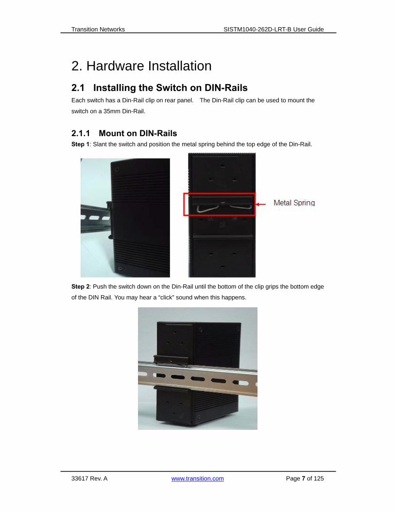
2.1.1 Mount on DIN-Rails Step 1: Slant the switch and position the metal spring behind the top edge of the Din-Rail.
Step 2: Push the switch down on the Din-Rail until the bottom of the clip grips the bottom edge
of the DIN Rail. You may hear a “click” sound when this happens.

Transition Networks SISTM1040-262D-LRT-B User Guide
33617 Rev. A www.transition.com Page 8 of 125
Pozidrive
2.2 Wall Mounting Installation
Each switch has also contains a wall mount bracket that can be found in the package. The
following steps show how to mount the switch on a panel or wall:
2.2.1 Mount on Wall
Step 1: Remove the Din-Rail clip by removing the 3 screws.
Step 2: Use the screws that can be found in the package to install the wall mount bracket.
The screw specifications are shown below. In order to prevent damage to the
SDSTX3110-121-LRT, the size of screws should not be larger or longer than the size used for
the DIN Rail clip.

Transition Networks SISTM1040-262D-LRT-B User Guide
33617 Rev. A www.transition.com Page 9 of 125
3. Hardware Overview
3.1 Front Panel
The following table describes the SISTM1040-262D-LRT-B front panel.
Port Description
10/100 RJ-45 fast
Ethernet ports
8 10/100Base-T(X) RJ-45 fast Ethernet ports support auto-negotiation.
Default Settings: Speed: auto, Duplex: auto, Flow control: disabled.
Gigabit RJ-45 port 2 10/100/1000Base-TX Giga ports (combo)
Fiber port 2 100/1000Base-X on SFP port (combo)
Console Use RS-232 to RJ-45 connecter to manage switch.
Reset Push Reset button for 2 to 3 seconds to reset the switch.
Push Reset button for 5 seconds to reset the switch to Factory default.
1. PWR: When the PWR UP, the green LED lights.
2. PWR1: When the PWR2 links, the green LED lights.
3. PWR2: When the PWR2 links, the green LED lights.
4. RM (Ring master): When lit, the switch is the ring master.

Transition Networks SISTM1040-262D-LRT-B User Guide
33617 Rev. A www.transition.com Page 10 of 125
5. Ring: When lit, the Ring is activated.
6. Fault: Indicates a Power failure or Port down/fail when lit.
7. Console port (RJ-45).
8. Reset button. Push the button 3 seconds for reset; 5 seconds for factory default.
9. 1000Base-X COMBO SFP Port Link/Act LED.
10. 1000Base-T gigabits Ethernet port COMBO 1000Base-X Fiber port on SFP.
11. 10/100/1000 Base-T(X) Ethernet ports Link LED.
12. 10/100/1000 Base-T(X) Ethernet ports ACT LED.
13. 10/100/1000 Base-T(X) Ethernet ports.
3.2 Front Panel LEDs
LED Color Status Description
PWR Green On DC power ready
PW1 Green On DC power module 1 activated.
PW2 Green On DC power module 2 activated.
R.M Green On O-Ring Master.
Ring Green
On Ring enabled.
Slowly blinking Ring has only One link (lack
of one link to build the ring).
Fast blinking Ring work normally.
Fault Amber On Fault relay. Power failure or
Port down/fail.
10/100Base-T(X) Fast Ethernet ports
LNK / ACT Green On Port link up.
Blinking Data transmitted.
Full Duplex Amber On Port works under full duplex.
Gigabit Ethernet ports
LNK/ACT Green On Port link up.
Blinking Data transmitted.
Indicator Amber On Port link on 100Mbps
SFP ports
LNK / ACT Green On Port link up.
Blinking Data transmitted.
Transition Networks SISTM1040-262D-LRT-B User Guide
33617 Rev. A www.transition.com Page 11 of 125
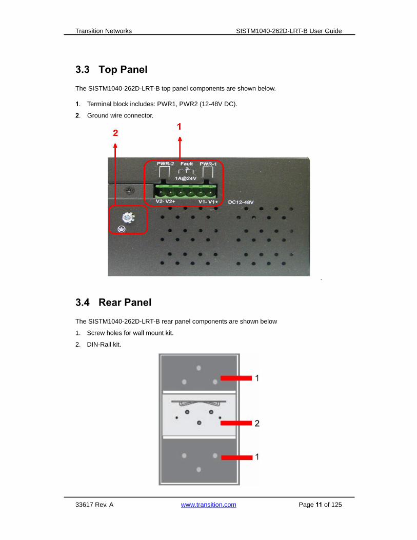
3.3 Top Panel
The SISTM1040-262D-LRT-B top panel components are shown below.
1. Terminal block includes: PWR1, PWR2 (12-48V DC).
2. Ground wire connector.
.
3.4 Rear Panel
The SISTM1040-262D-LRT-B rear panel components are shown below
1. Screw holes for wall mount kit.
2. DIN-Rail kit.

Transition Networks SISTM1040-262D-LRT-B User Guide
33617 Rev. A www.transition.com Page 12 of 125
4. Cables
4.1 Ethernet Cables
The SISTM1040-262D-LRT-B switch has standard Ethernet ports. Based on the link type, the
switch uses CAT 3, 4, 5, or 5e UTP cables to connect to other network equipment (PCs,
servers, switches, routers, or hubs). Refer to the following table for cable specifications.
Cable Types and Specifications:
Cable Type Max. Length Connector
10BASE-T Cat.3, 4, 5 100-ohm UTP 100 m (328 ft) RJ-45
100BASE-TX Cat.5 100-ohm UTP UTP 100 m (328 ft) RJ-45
1000BASE-TX Cat.5/Cat.5e 100-ohm UTP UTP 100 m (328ft) RJ-45
4.1.1 10/100/100BASE-TX/10BASE-T Pin Assignments For 100BASE-TX/10BASE-T cables, pins 1 and 2 are used for transmitting data, and pins 3
and 6 are used for receiving data.
1000 Base-T RJ-45 Pin Assignments :
Pin Number Assignment
1 BI_DA+
2 BI_DA-
3 BI_DB+
4 BI_DC+
5 BI_DC-
6 BI_DB-
7 BI_DD+
8 BI_DD-

Transition Networks SISTM1040-262D-LRT-B User Guide
33617 Rev. A www.transition.com Page 13 of 125
The SISTM1040-262D-LRT-B supports auto MDI/MDI-X operation. Straight- through or
cross-over cables can be used to connect the switch to other equipment. The following table
below shows the 10BASE-T/ 100BASE-TX MDI and MDI-X port pin outs.
10/100 Base-TX MDI/MDI-X pins assignment:
Pin Number MDI port MDI-X port
1 TD+(transmit) RD+(receive)
2 TD-(transmit) RD-(receive)
3 RD+(receive) TD+(transmit)
4 Not used Not used
5 Not used Not used
6 RD-(receive) TD-(transmit)
7 Not used Not used
8 Not used Not used
1000 Base-T MDI/MDI-X pins assignment:
Pin Number MDI port MDI-X port
1 BI_DA+ BI_DB+
2 BI_DA- BI_DB-
3 BI_DB+ BI_DA+
4 BI_DC+ BI_DD+
5 BI_DC- BI_DD-
6 BI_DB- BI_DA-
7 BI_DD+ BI_DC+
8 BI_DD- BI_DC-
Note: “+” and “-” signs represent the polarity of the wires that make up each wire pair.

Transition Networks SISTM1040-262D-LRT-B User Guide
33617 Rev. A www.transition.com Page 14 of 125
4.2 SFPs
The ISTM1040-262D-LRT-B has fiber optical ports with SFP connectors. The fiber optical ports
are in multi-mode and single-mode with LC connector. Note that the TX port of Switch A should
be connected to the RX port of Switch B.
4.3 Console Cable
SISTM1040-262D-LRT-B switch can be managed through the serial console port. A DB-9 to
RJ-45 cable can be found in the package. This cable can be used to connect a PC via a
RS-232 cable with DB-9 female connector and the other end (RJ-45 connector) connects to
console port of switch.
PC pin out (male) RS-232 with DB9 female connector DB9 to RJ-45
Pin #2 RD Pin #2 TD Pin #2
Pin #3 TD Pin #3 RD Pin #3
Pin #5 GD Pin #5 GD Pin #5
Transition Networks SISTM1040-262D-LRT-B User Guide
33617 Rev. A www.transition.com Page 15 of 125
5. WEB Management Warning!!! While configuring or upgrading firmware, please remove physical loop connection
first. DO NOT power off equipment during firmware upgrading!
5.1 Configuration by Web Browser
This section introduces the configuration via a Web browser.
5.1.1 About Web-based Management
The switch contains an embedded HTML web server. It contains advanced management
features and allows you to manage the switch from anywhere on the network through a
standard web browser such as Microsoft Internet Explorer. The Web-Based Management
function supports Internet Explorer 5.0 or later. It is based on Java Applets with an aim to
reduce network bandwidth consumption, enhance access speed and present an easy viewing
screen. Note: By default, IE5.0 or later versions do not allow Java Applets to open sockets.
You must explicitly modify the browser setting in order to enable Java Applets to use network
ports.
Preparing for Web Management
The default values are:
IP Address: 192.168.1.77
Subnet Mask: 255.255.255.0
Default Gateway: 192.168.1.254
User Name: root
Password: root

Transition Networks SISTM1040-262D-LRT-B User Guide
33617 Rev. A www.transition.com Page 16 of 125
System Login
1. Launch the web browser (e.g., Internet Explorer).
2. Type http:// and the IP address of the switch. Press “Enter”.
3. The login screen displays.
4. Key in the username and password. The default username and password is “admin”.
5. Click the ”OK” button. The main interface of the Web-based management displays.
Main Interface

Transition Networks SISTM1040-262D-LRT-B User Guide
33617 Rev. A www.transition.com Page 17 of 125
5.1.2 System Information
System Information
The system information will display the Basic Setting / Switch Setting page.
Enable Location Alert
When you click , the front panel PWR1, PWR2 and PWR3 LEDs
start flashing. Click to cause the LEDs to stop flashing.
5.1.3 Front Panel Show the panel of the SISTM1040-262D-LRT-B. Click “Close” to close panel on web.

Transition Networks SISTM1040-262D-LRT-B User Guide
33617 Rev. A www.transition.com Page 18 of 125
5.1.4 Basic setting
5.1.4.1 Switch Setting
The following table describes the labels in this screen.
Label Description
System Name Assign the name of switch. The maximum length is 64 bytes.
System Description Display the description of switch.
System Location Assign the switch physical location. The maximum length is 64
bytes.
System Contact Enter the name of contact person or organization.
System OID Display the switch’s OID (object identifier) information.
Firmware Version Display the switch’s firmware version.
Kernel Version Display the kernel software version.
Device MAC Display the unique hardware address assigned by manufacturer
(default).

Transition Networks SISTM1040-262D-LRT-B User Guide
33617 Rev. A www.transition.com Page 19 of 125
5.1.4.2 Admin Password
Change web management login username and password for the management security issue
The following table describes the labels in this screen.
Label Description
User Name Key in the new username (the default is “root”).
New Password Key in the new password (the default is “root”).
Confirm password Re-type the new password.
Apply Click “Apply” to activate the configurations.
Transition Networks SISTM1040-262D-LRT-B User Guide
33617 Rev. A www.transition.com Page 20 of 125
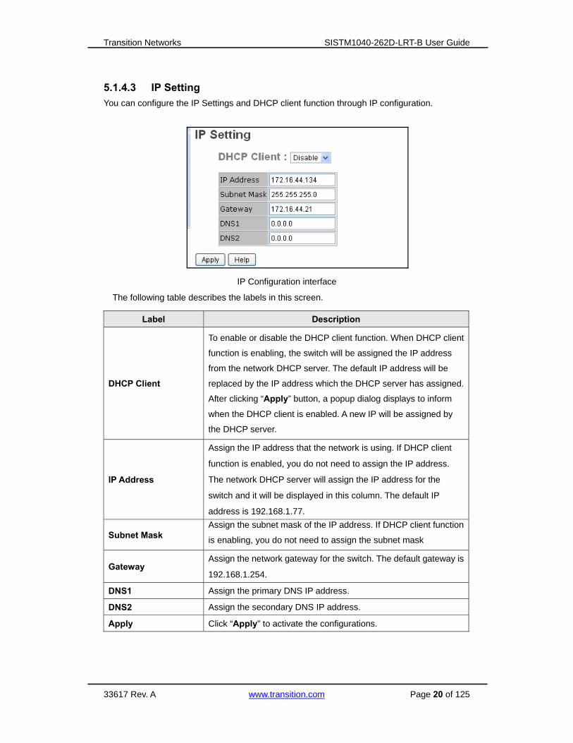
5.1.4.3 IP Setting
You can configure the IP Settings and DHCP client function through IP configuration.
IP Configuration interface
The following table describes the labels in this screen.
Label Description
DHCP Client
To enable or disable the DHCP client function. When DHCP client
function is enabling, the switch will be assigned the IP address
from the network DHCP server. The default IP address will be
replaced by the IP address which the DHCP server has assigned.
After clicking “Apply” button, a popup dialog displays to inform
when the DHCP client is enabled. A new IP will be assigned by
the DHCP server.
IP Address
Assign the IP address that the network is using. If DHCP client
function is enabled, you do not need to assign the IP address.
The network DHCP server will assign the IP address for the
switch and it will be displayed in this column. The default IP
address is 192.168.1.77.
Subnet Mask Assign the subnet mask of the IP address. If DHCP client function
is enabling, you do not need to assign the subnet mask
Gateway Assign the network gateway for the switch. The default gateway is
192.168.1.254.
DNS1 Assign the primary DNS IP address.
DNS2 Assign the secondary DNS IP address.
Apply Click “Apply” to activate the configurations.
Transition Networks SISTM1040-262D-LRT-B User Guide
33617 Rev. A www.transition.com Page 21 of 125
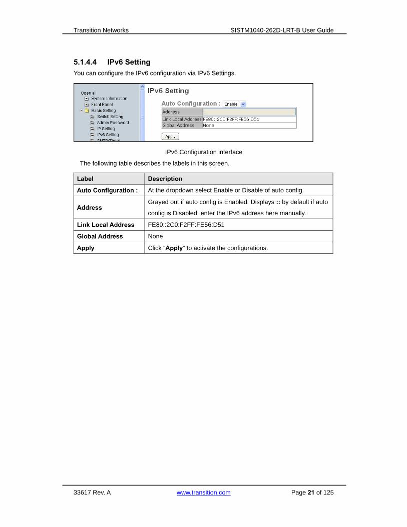
5.1.4.4 IPv6 Setting
You can configure the IPv6 configuration via IPv6 Settings.
IPv6 Configuration interface
The following table describes the labels in this screen.
Label Description
Auto Configuration : At the dropdown select Enable or Disable of auto config.
Address Grayed out if auto config is Enabled. Displays :: by default if auto
config is Disabled; enter the IPv6 address here manually.
Link Local Address FE80::2C0:F2FF:FE56:D51
Global Address None
Apply Click “Apply” to activate the configurations.
Transition Networks SISTM1040-262D-LRT-B User Guide
33617 Rev. A www.transition.com Page 22 of 125
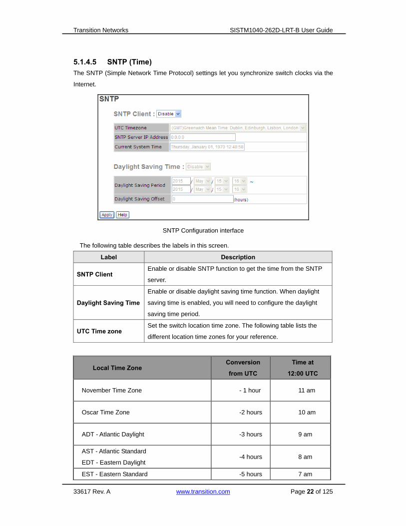
5.1.4.5 SNTP (Time)
The SNTP (Simple Network Time Protocol) settings let you synchronize switch clocks via the
Internet.
SNTP Configuration interface
The following table describes the labels in this screen.
Label Description
SNTP Client Enable or disable SNTP function to get the time from the SNTP
server.
Daylight Saving Time
Enable or disable daylight saving time function. When daylight
saving time is enabled, you will need to configure the daylight
saving time period.
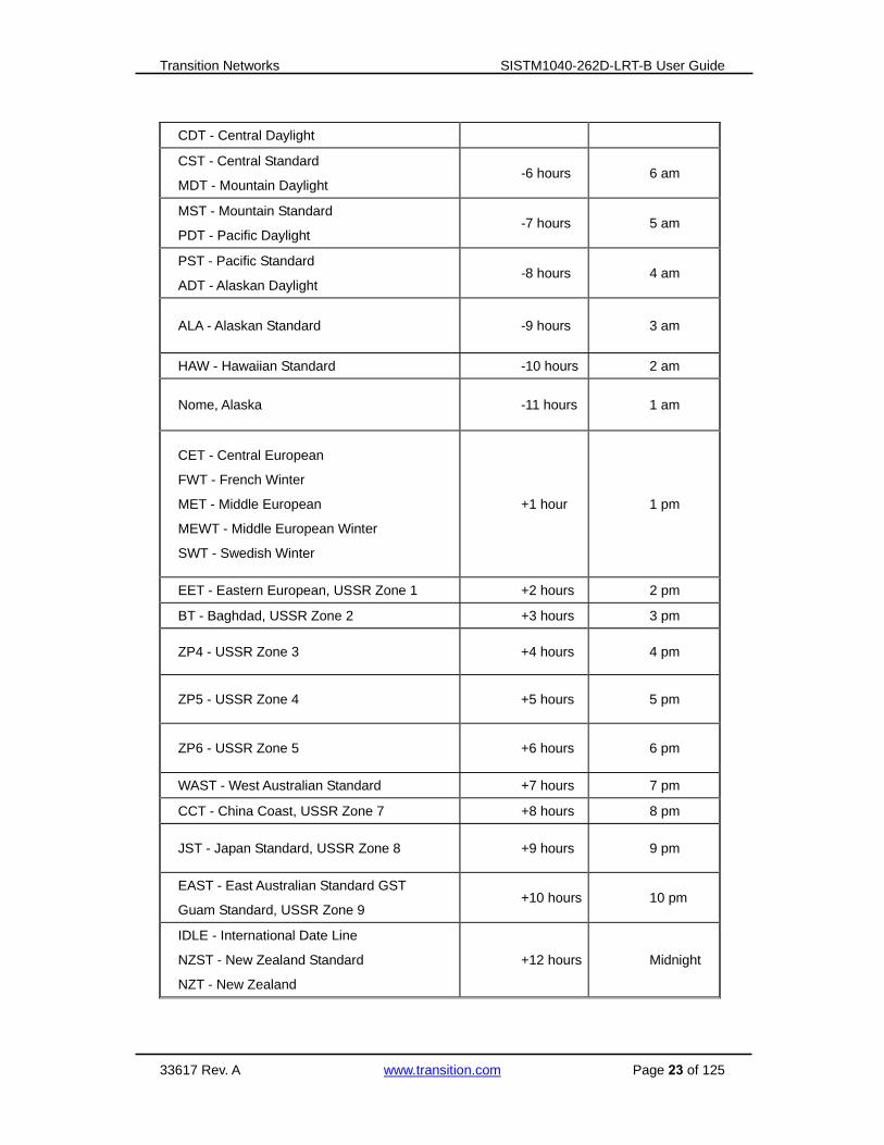
UTC Time zone Set the switch location time zone. The following table lists the
different location time zones for your reference.
Local Time Zone Conversion
from UTC
Time at
12:00 UTC
November Time Zone - 1 hour 11 am
Oscar Time Zone -2 hours 10 am
ADT - Atlantic Daylight -3 hours 9 am
AST - Atlantic Standard
EDT - Eastern Daylight -4 hours 8 am
EST - Eastern Standard -5 hours 7 am
Transition Networks SISTM1040-262D-LRT-B User Guide
33617 Rev. A www.transition.com Page 23 of 125
CDT - Central Daylight
CST - Central Standard
MDT - Mountain Daylight -6 hours 6 am
MST - Mountain Standard
PDT - Pacific Daylight -7 hours 5 am
PST - Pacific Standard
ADT - Alaskan Daylight -8 hours 4 am
ALA - Alaskan Standard -9 hours 3 am
HAW - Hawaiian Standard -10 hours 2 am
Nome, Alaska -11 hours 1 am
CET - Central European
FWT - French Winter
MET - Middle European
MEWT - Middle European Winter
SWT - Swedish Winter
+1 hour 1 pm
EET - Eastern European, USSR Zone 1 +2 hours 2 pm
BT - Baghdad, USSR Zone 2 +3 hours 3 pm
ZP4 - USSR Zone 3 +4 hours 4 pm
ZP5 - USSR Zone 4 +5 hours 5 pm
ZP6 - USSR Zone 5 +6 hours 6 pm
WAST - West Australian Standard +7 hours 7 pm
CCT - China Coast, USSR Zone 7 +8 hours 8 pm
JST - Japan Standard, USSR Zone 8 +9 hours 9 pm
EAST - East Australian Standard GST
Guam Standard, USSR Zone 9 +10 hours 10 pm
IDLE - International Date Line
NZST - New Zealand Standard
NZT - New Zealand
+12 hours Midnight

Transition Networks SISTM1040-262D-LRT-B User Guide
33617 Rev. A www.transition.com Page 24 of 125
Label Description
SNTP Sever IP Address Set the SNTP server IP address.
Daylight Saving Period Set up the Daylight Saving beginning time and Daylight
Saving ending time. Both will be different each year.
Daylight Saving Offset Set up the offset time.
Switch Timer Display the switch current time.
Apply Click “Apply” to activate the configurations.
5.1.4.6 LLDP
LLDP (Link Layer Discovery Protocol) function allows the switch to provide its information to
other nodes on the network and store the information it discovers.
LLDP configuration interface
The following table describes the labels in this screen.
Label Description
LLDP Protocol “Enable” or “Disable” LLDP function.
LLDP Interval The interval of sending LLDP information (the default is 30 seconds)
Apply Click “Apply” to activate the configurations.
Help Show help file.

Transition Networks SISTM1040-262D-LRT-B User Guide
33617 Rev. A www.transition.com Page 25 of 125
5.1.4.7 Auto Provision
Auto Provision allows you to update the switch firmware automatically. You can put the
firmware or configuration file on a TFTP server. When you reboot the switch, it will upgrade
automatically. Before updating, make sure you have your TFTP server ready and the firmware
image and configuration file on the TFTP server.
Auto Provision interface
Label Description
Auto Install
Configuration file from
TFTP server?
Check to “Enable” or uncheck to “Disable” the Auto Install
function.
TFTP Server IP Address Enter the IP address of the TFTP server.
Configuration File Name Enter the config filename with a .bin suffix.
Auto Install Firmware
image file from TFTP
server?
Check to “Enable” or uncheck to “Disable” the Auto Install
function.
TFTP Server IP Address Enter the IP address of the TFTP server.
Firmware File Name Enter the config filename with a .bin suffix.
Apply Click “Apply” to activate the configuration settings.
Help Show help file.

Transition Networks SISTM1040-262D-LRT-B User Guide
33617 Rev. A www.transition.com Page 26 of 125
5.1.4.8 Backup & Restore
You can save the current configuration from the switch to a TFTP server, or restore the
configuration from a TFTP server on this page.
Backup & Restore interface
The following table describes the labels in this screen.
Label Description
TFTP Server IP Address Fill in the TFTP server IP address.
Restore File Name Type in the file name (xxxxx.bin).
Restore Click the “Restore” button to restore the configurations.
Backup File Name Type in the file name (xxxxx.bin).
Backup Click “backup” to backup the configurations.

Transition Networks SISTM1040-262D-LRT-B User Guide
33617 Rev. A www.transition.com Page 27 of 125
5.1.4.9 Upgrade Firmware
Upgrade Firmware allows you to update the firmware of the switch. Before updating, make
sure you have your TFTP server ready and the firmware image is on the TFTP server.
Update Firmware interface
Label Description
TFTP Server IP Enter the IP address of the TFTP server.
Firmware File Name Enter the firmware filename with a .bin suffix.
Upgrade Click the Upgrade button to update the switch firmware.

Transition Networks SISTM1040-262D-LRT-B User Guide
33617 Rev. A www.transition.com Page 28 of 125
5.1.5 DHCP Server 5.1.5.1 DHCP Server – Setting
The system provides a DHCP server function. If enabled the switch system will be a DHCP
server.
DHCP Server Configuration interface
The following table describes the labels in this screen.
Label Description
DHCP Server Enable or Disable the DHCP Server function. Enable – the
switch will be the DHCP server on your local network
Start IP Address
The dynamic IP assign range. Low IP address is the beginning
of the dynamic IP assigns range. For example: dynamic IP
assign range is from 192.168.1.100 to 192.168.1.200.
192.168.1.100 will be the Start IP address.
End IP Address
The dynamic IP assign range. High IP address is the end of the
dynamic IP assigns range. For example: dynamic IP assign
range is from 192.168.1.100 to 192.168.1.200. 192.168.1.200
will be the End IP address
Subnet Mask The dynamic IP assign range subnet mask
Gateway The gateway in your network.
DNS Domain Name Server IP Address in your network.
Lease Time (Hour) It is the period of time before the system will reset the assigned
dynamic IP to ensure the IP address is in used.
Apply Click “Apply” to activate the configurations.

Transition Networks SISTM1040-262D-LRT-B User Guide
33617 Rev. A www.transition.com Page 29 of 125
5.1.5.2 DHCP Server – Client List
When the DHCP server function is activated, the system will collect the DHCP client
information and display it here.
DHCP Server Client Entries interface
5.1.5.3 DHCP Server – Port and IP bindings
You can assign the specific IP addresses that are in the assigned dynamic IP range to specific
ports. When a device is connecting to the port and asks for an IP address, the system will
assign the IP address that was assigned to the previous device connected to that port.
DHCP Server Port and IP Binding interface

Transition Networks SISTM1040-262D-LRT-B User Guide
33617 Rev. A www.transition.com Page 30 of 125
5.1.6 Port Setting 5.1.6.1 Port Control
This function lets you set the state, speed/duplex, flow control, and security of the ports.
Port Control interface
The following table describes the labels in this screen.
Label Description
Port No. Port number for setting.
State Dropdown to select Enable or Disable.
Speed/Duplex You can set AutoNegotiation, 100 full, 100 half, 10 full or 10 half.
Flow Control Select Symmetric or Asymmetric mode to avoid packet loss when
congestion occurres.
Security Enable or Disable port security function. When enabled, the port will
STOP learning MAC address dynamically.
Apply Click “Apply” to activate the configurations.

Transition Networks SISTM1040-262D-LRT-B User Guide
33617 Rev. A www.transition.com Page 31 of 125
5.1.6.2 Port Status
The following information provides the current port status information:
Port Status interface
Transition Networks SISTM1040-262D-LRT-B User Guide
33617 Rev. A www.transition.com Page 32 of 125
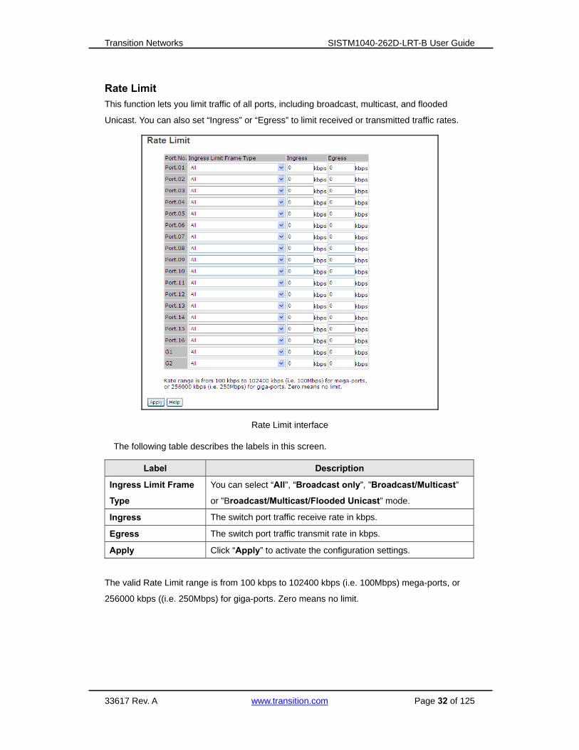
Rate Limit
This function lets you limit traffic of all ports, including broadcast, multicast, and flooded
Unicast. You can also set “Ingress” or “Egress” to limit received or transmitted traffic rates.
Rate Limit interface
The following table describes the labels in this screen.
Label Description
Ingress Limit Frame
Type
You can select “All”, “Broadcast only”, ”Broadcast/Multicast”
or ”Broadcast/Multicast/Flooded Unicast” mode.
Ingress The switch port traffic receive rate in kbps.
Egress The switch port traffic transmit rate in kbps.
Apply Click “Apply” to activate the configuration settings.
The valid Rate Limit range is from 100 kbps to 102400 kbps (i.e. 100Mbps) mega-ports, or
256000 kbps ((i.e. 250Mbps) for giga-ports. Zero means no limit.
Transition Networks SISTM1040-262D-LRT-B User Guide
33617 Rev. A www.transition.com Page 33 of 125
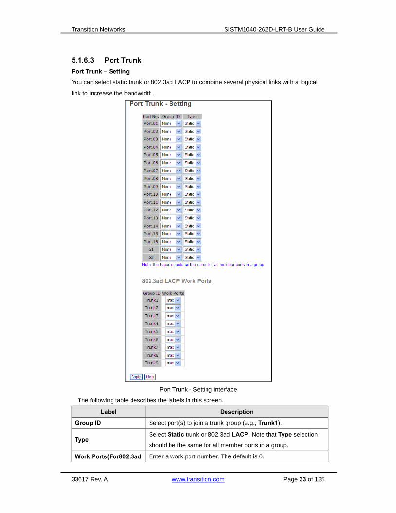
5.1.6.3 Port Trunk
Port Trunk – Setting
You can select static trunk or 802.3ad LACP to combine several physical links with a logical
link to increase the bandwidth.
Port Trunk - Setting interface
The following table describes the labels in this screen.
Label Description
Group ID Select port(s) to join a trunk group (e.g., Trunk1).
Type Select Static trunk or 802.3ad LACP. Note that Type selection
should be the same for all member ports in a group.
Work Ports(For802.3ad Enter a work port number. The default is 0.

Transition Networks SISTM1040-262D-LRT-B User Guide
33617 Rev. A www.transition.com Page 34 of 125
LACP only)
Apply Click “Apply” to activate the configuration settings.
Port Trunk – Status
You can check the configuration of port trunk.
Port Trunk - Status interface
The following table describes the labels in this screen.
Label Description
Group ID Select port to join a trunk group.
Trunk Member Whether a member of the trunk group.
Type Support Static trunk and 802.3ad LACP.

Transition Networks SISTM1040-262D-LRT-B User Guide
33617 Rev. A www.transition.com Page 35 of 125
5.1.7 Redundancy 5.1.7.1 Redundant Ring
This feature provides one of the most powerful Redundant Ring technologies in the world.
The recovery time is less than 10 ms over 250 units of connections. It can reduce unexpected
malfunctions caused by network topology changes. O-Ring technology supports three Ring
topologies for network redundancy: O-Ring, Coupling Ring, and Dual Homing.
O-Ring interface
The following table describes the labels in this screen.
Label Description
O-Ring Tick the checkbox to enable O-Ring.
Ring Master
There should be one and only one Ring Master in a ring. However, if
there are two or more switches set as the Ring Master, the switch with
the lowest MAC address will be the actual Ring Master and others will
be Backup Ring Masters.
1st Ring Port The primary port, when this switch is configured in O-Ring.
2nd Ring Port The backup port, when this switch is configured in O-Ring.
Coupling Ring
Tick the checkbox to enable Coupling Ring. Coupling Ring can be used
to divide a big ring into two smaller Rings to avoid effecting all switches
when network topology changes. It is a good application for connecting
two Rings.
Coupling Port
Set a port as coupling port to link to the Coupling Port of the switch in
another ring. Coupling Ring needs four switches to construct an active
and a backup link. The coupled four ports of four switches will be
operated at active/backup mode.
Control Port Set a port as Control Port to link to the Control Port of the switch in the
same ring. Control Port used to transmit control signals.

Transition Networks SISTM1040-262D-LRT-B User Guide
33617 Rev. A www.transition.com Page 36 of 125
Dual Homing
Tick the checkbox to enable Dual Homing mode. By selecting Dual
Homing mode, the Ring will be connected to normal switches through
two RSTP links (i.e., backbone Switch). The two links act as
active/backup mode, and connect each Ring to the normal switches in
RSTP mode.
Apply Click the “Apply” button to activate the configuration.
Note: It is not recommended to set one switch as a Ring Master and as Coupling Ring at the
same time due to heavy load of system.

Transition Networks SISTM1040-262D-LRT-B User Guide
33617 Rev. A www.transition.com Page 37 of 125
5.1.7.2 Redundant Ring
Redundant Ring technology can be applied for other vendor’s proprietary ring. Thus, you can
add SISTM switches into the network constructed by other ring technology and enable
Redundant Ring to inter-operate with other vendor’s managed switches.
Redundant Ring interface
Label Description
Ring Master Select Enable to select the the Redundant Ring function.
1st Ring Port Choose the port which connects to the ring.
2nd Ring Port Choose the port which connects to the ring.
Messages: This switch is Master switch.

Transition Networks SISTM1040-262D-LRT-B User Guide
33617 Rev. A www.transition.com Page 38 of 125
A Redundant Ring connection application example is shown below.
Open-Ring connection

Transition Networks SISTM1040-262D-LRT-B User Guide
33617 Rev. A www.transition.com Page 39 of 125
Multiple Ring
Multiple Ring interface
Label Description
Enable Check to Enable the Open-Ring function.
1st Choose the first Uplink port.
2nd Choose the second Uplink port.
Uplink Port At the dropdown, select the port number(s).
Edge Port Check the checkbox if the port is to be an Edge Port.
State e.g., Forwarding, Linkdown.

Transition Networks SISTM1040-262D-LRT-B User Guide
33617 Rev. A www.transition.com Page 40 of 125
5.1.7.3 RSTP
The Rapid Spanning Tree Protocol (RSTP) is an evolution of the Spanning Tree Protocol (STP).
It provides faster convergence of spanning tree after a topology change. The system also
supports STP and the system will detect if the connected device is running STP or RSTP
protocol automatically.
RSTP Setting
You can enable/disable RSTP function, and set parameters for each port.
RSTP Setting interface
The following table describes the RSTP Setting screen labels.
Label Description
RSTP Mode You must enable the RSTP function before configuring the related
parameters.
Priority (0-61440)
A value used to identify the root bridge. The bridge with the lowest value
has the highest priority and is selected as the root. If the value changes,
you must restart the switch. The Bridge Priority value must be a multiple
of 4096 according to the protocol rules.
Max Age Time
(6-40)
The number of seconds (6-40) for a bridge to wait without receiving
Spanning-tree Protocol configuration messages before reconfiguration.

Transition Networks SISTM1040-262D-LRT-B User Guide
33617 Rev. A www.transition.com Page 41 of 125
Hello Time (1-10) The time interval when a switch sends out the BPDU (Bridge Protocol
Data Unit) packet to check RSTP current status. Enter a value of 1 - 10.
Forwarding Delay
Time (4-30)
The number of seconds a port waits before changing from its
learning/listening state to forwarding state. Enter a value of 4 - 30.
Path Cost
(1-200000000)
The cost of the path to the other bridge from this transmitting bridge at
the specified port. Enter a number 1 - 200000000.
Priority (0-240) Decide which port should be blocked by setting the priority in LAN.
Enter a number 0 - 240. The Port Priority value must be a multiple of 16.
Admin P2P
Some of the rapid state transactions that are possible within RSTP
depend on whether the port can only be connected to exactly one other
bridge (i.e., it is served by a point-to-point LAN segment), or it can be
connected to two or more bridges (i.e., it is served by a shared medium
LAN segment). This function allows the P2P status of the link to be
manipulated administratively. True means P2P enabled. False means
P2P disabled.
Admin Edge
The port directly connected to end stations that cannot create a bridging
loop in the network. To configure the port as an edge port, set the port to
“True”.
Admin Non STP The port includes the STP mathematic calculation. True: STP algorithm
is included, False: STP algorithm is not included.
Apply Click “Apply” to activate the configurations.
NOTE: Follow the rule to configure the MAX Age, Hello Time, and Forward Delay Time:
2 x (Forward Delay Time value –1) ≥ Max Age value ≥ 2 x (Hello Time value +1)
Messages

Transition Networks SISTM1040-262D-LRT-B User Guide
33617 Rev. A www.transition.com Page 42 of 125
RSTP Information
This table shows the RSTP algorithm results.
RSTP Information interface
See the previous section for the RSTP Information screen label descriptions.

Transition Networks SISTM1040-262D-LRT-B User Guide
33617 Rev. A www.transition.com Page 43 of 125
5.1.7.4 MSTP
Multiple Spanning Tree Protocol (MSTP) is a standard protocol based on IEEE 802.1s.
MSTP maps several VLANs to a reduced number of spanning tree instances since most
networks do not need more than a few logical topologies. It supports a load balancing scheme
and is less CPU intensive than PVST (Cisco proprietary technology).
MSTP > Bridge Setting
MSTP Setting interface
The following table describes the labels in this screen.
Label Description
MSTP Enable You must enable or disable MSTP function before configuring the
related parameters.
Force Version The Force Version parameter can be used to force a VLAN Bridge
that supports RSTP to operate in an STP-compatible manner.
Configuration Name The same MST Region must have the same MST configuration
name.
Revision Level
(0-65535) The same MST Region must have the same revision level.
Priority (0-61440)
A value used to identify the root bridge. The bridge with the lowest
value has the highest priority and is selected as the root. If the
value changes, You must reboot the switch. The value must be a
multiple of 4096 per the protocol standard rule.

Transition Networks SISTM1040-262D-LRT-B User Guide
33617 Rev. A www.transition.com Page 44 of 125
Max Age Time(6-40)
The number of seconds a bridge waits without receiving
Spanning-tree Protocol configuration messages before attempting
a reconfiguration. Enter a value of 6 - 40.
Hello Time (1-10)
The setting follows the rule below to configure the MAX Age, Hello
Time, and Forward Delay Time before a controlled switch sends
out the BPDU packet to check RSTP current status. Enter a value
of 1 - 10.
2 x (Forward Delay Time value –1) ≥ Max Age value ≥ 2 x (Hello Time value
+1)
Forwarding Delay
Time (4-30)
The number of seconds a port waits before changing from its
Rapid Spanning-Tree Protocol learning and listening states to the
forwarding state. Enter a value of 4 - 30.
Max Hops (1-40)
This parameter is additional to those specified for RSTP. A single
value applies to all Spanning Trees within an MST Region (the
CIST and all MSTIs) for which the Bridge is the Regional Root.
Apply Click “Apply” to activate the configurations.
After the settings are applied, the CIST Root Bridge Information displays:
Transition Networks SISTM1040-262D-LRT-B User Guide
33617 Rev. A www.transition.com Page 45 of 125
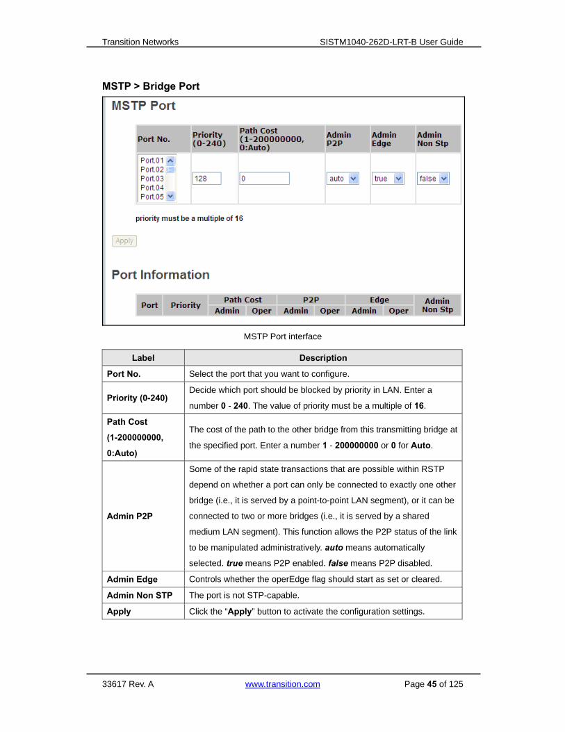
MSTP > Bridge Port
MSTP Port interface
Label Description
Port No. Select the port that you want to configure.
Priority (0-240) Decide which port should be blocked by priority in LAN. Enter a
number 0 - 240. The value of priority must be a multiple of 16.
Path Cost
(1-200000000,
0:Auto)
The cost of the path to the other bridge from this transmitting bridge at
the specified port. Enter a number 1 - 200000000 or 0 for Auto.
Admin P2P
Some of the rapid state transactions that are possible within RSTP
depend on whether a port can only be connected to exactly one other
bridge (i.e., it is served by a point-to-point LAN segment), or it can be
connected to two or more bridges (i.e., it is served by a shared
medium LAN segment). This function allows the P2P status of the link
to be manipulated administratively. auto means automatically
selected. true means P2P enabled. false means P2P disabled.
Admin Edge Controls whether the operEdge flag should start as set or cleared.
Admin Non STP The port is not STP-capable.
Apply Click the “Apply” button to activate the configuration settings.

Transition Networks SISTM1040-262D-LRT-B User Guide
33617 Rev. A www.transition.com Page 46 of 125
After the settings are applied, the CIST Root Bridge Information displays:
Transition Networks SISTM1040-262D-LRT-B User Guide
33617 Rev. A www.transition.com Page 47 of 125
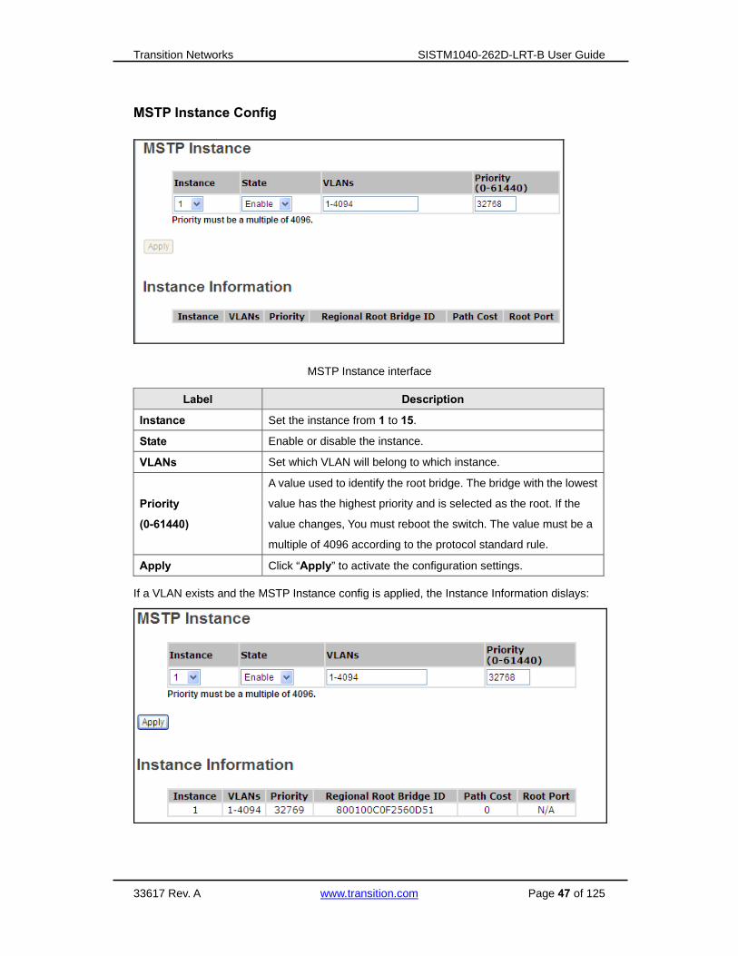
MSTP Instance Config
MSTP Instance interface
Label Description
Instance Set the instance from 1 to 15.
State Enable or disable the instance.
VLANs Set which VLAN will belong to which instance.
Priority
(0-61440)
A value used to identify the root bridge. The bridge with the lowest
value has the highest priority and is selected as the root. If the
value changes, You must reboot the switch. The value must be a
multiple of 4096 according to the protocol standard rule.
Apply Click “Apply” to activate the configuration settings.
If a VLAN exists and the MSTP Instance config is applied, the Instance Information dislays:

Transition Networks SISTM1040-262D-LRT-B User Guide
33617 Rev. A www.transition.com Page 48 of 125
MSTP Instance Port Config
MSTP Instance Port interface
Label Description
Instance Set the instance’s information except CIST.
Port Select the port that you want to configure.
Priority
(0-240)
Select the port to be blocked by priority in LAN. Enter 0 - 240.
The value of priority must be a multiple of 16.
Path Cost
(1-200000000, 0:Auto
The cost of the path to the other bridge from this transmitting
bridge at the specified port. Enter a number 1 - 200000000 or 0
for Auto.
Apply Click the “Apply” button to set the configurations.
Messages: Apply fail - Another redundancy protocol is running. Only one could be run at
the same time

Transition Networks SISTM1040-262D-LRT-B User Guide
33617 Rev. A www.transition.com Page 49 of 125
After the settings are applied, the Instance Port Information displays:
Transition Networks SISTM1040-262D-LRT-B User Guide
33617 Rev. A www.transition.com Page 50 of 125
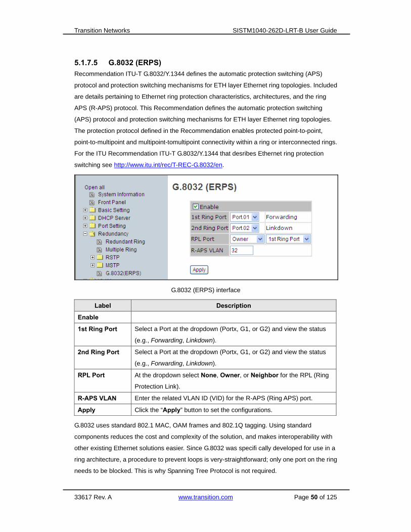
5.1.7.5 G.8032 (ERPS)
Recommendation ITU-T G.8032/Y.1344 defines the automatic protection switching (APS)
protocol and protection switching mechanisms for ETH layer Ethernet ring topologies. Included
are details pertaining to Ethernet ring protection characteristics, architectures, and the ring
APS (R-APS) protocol. This Recommendation defines the automatic protection switching
(APS) protocol and protection switching mechanisms for ETH layer Ethernet ring topologies.
The protection protocol defined in the Recommendation enables protected point-to-point,
point-to-multipoint and multipoint-tomultipoint connectivity within a ring or interconnected rings.
For the ITU Recommendation ITU-T G.8032/Y.1344 that desribes Ethernet ring protection
switching see http://www.itu.int/rec/T-REC-G.8032/en.
G.8032 (ERPS) interface
Label Description
Enable
1st Ring Port Select a Port at the dropdown (Portx, G1, or G2) and view the status
(e.g., Forwarding, Linkdown).
2nd Ring Port Select a Port at the dropdown (Portx, G1, or G2) and view the status
(e.g., Forwarding, Linkdown).
RPL Port At the dropdown select None, Owner, or Neighbor for the RPL (Ring
Protection Link).
R-APS VLAN Enter the related VLAN ID (VID) for the R-APS (Ring APS) port.
Apply Click the “Apply” button to set the configurations.
G.8032 uses standard 802.1 MAC, OAM frames and 802.1Q tagging. Using standard
components reduces the cost and complexity of the solution, and makes interoperability with
other existing Ethernet solutions easier. Since G.8032 was specifi cally developed for use in a
ring architecture, a procedure to prevent loops is very-straightforward; only one port on the ring
needs to be blocked. This is why Spanning Tree Protocol is not required.
Transition Networks SISTM1040-262D-LRT-B User Guide
33617 Rev. A www.transition.com Page 51 of 125
5.1.8 VLAN A Virtual LAN (VLAN) is a logical network grouping that limits the broadcast domain, which
allows you to isolate network traffic. Only the members of the same VLAN will receive the
traffic from the other members. Basically, to create a VLAN from a switch is logically equivalent
to separating a group of network devices. However, all the network devices are still plugged
into the same switch physically. This switch supports port-based and 802.1Q (tagged-based)
VLAN. The default configuration of VLAN operation mode is at “802.1Q”.
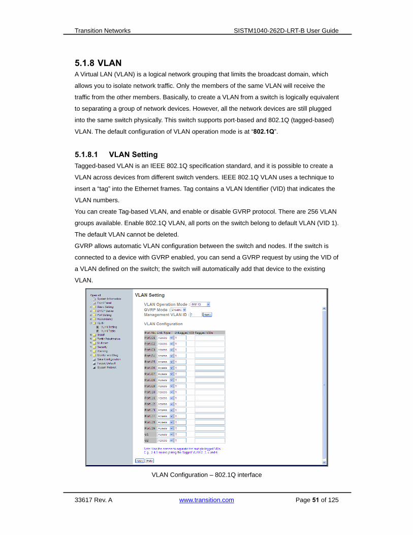
5.1.8.1 VLAN Setting
Tagged-based VLAN is an IEEE 802.1Q specification standard, and it is possible to create a
VLAN across devices from different switch venders. IEEE 802.1Q VLAN uses a technique to
insert a “tag” into the Ethernet frames. Tag contains a VLAN Identifier (VID) that indicates the
VLAN numbers.
You can create Tag-based VLAN, and enable or disable GVRP protocol. There are 256 VLAN
groups available. Enable 802.1Q VLAN, all ports on the switch belong to default VLAN (VID 1).
The default VLAN cannot be deleted.
GVRP allows automatic VLAN configuration between the switch and nodes. If the switch is
connected to a device with GVRP enabled, you can send a GVRP request by using the VID of
a VLAN defined on the switch; the switch will automatically add that device to the existing
VLAN.
VLAN Configuration – 802.1Q interface

Transition Networks SISTM1040-262D-LRT-B User Guide
33617 Rev. A www.transition.com Page 52 of 125
The following table describes the 802.1Q VLAN labels on this screen. Note that the ports
with the same VID means in the same VLAN group.
Label Description
VLAN Operation
Mode Configure VLAN Operation Mode: Disable, Port Based, or 802.1Q.
GVRP Mode Enable or Disable the GVRP function globally.
Management
VLAN ID
Management VLAN provides network administrators a secured VLAN
for switch management. Only the devices in the Management VLAN
can access the switch. Zero (0) means this function is disabled.
Link Type
The available Link Types are:
Access: single switch only; allows you to group ports by setting the
same VID. The Access link only supports an untagged VID.
1QTrunk: extended application of Access Link, allows you to group
ports by setting the same VID with 2 or more switches. The 1Q Trunk
link only supports multiple tagged VIDs.
Hybrid: Both Access Link and Trunk Link are available. The Hybrid
link supports an untagged VID and multiple tagged VIDs.
Untagged VID Set the port default VLAN ID for untagged devices that connect to the
port. The range is 1 - 4094.
Tagged VIDs
Set the tagged VIDs to carry different VLAN frames to the other switch.
Tagged VIDs support 1~4094 and multiple VIDs. Use the comma to
separate the multiple tagged VIDs (e.g., 2,3,4 means joining the
Tagged VLAN 2,3 and 4).
Apply Click the “Apply” button to activate the configurations.

Transition Networks SISTM1040-262D-LRT-B User Guide
33617 Rev. A www.transition.com Page 53 of 125
5.1.8.2 VLAN Setting – Port Based
Packets can go among only members of the same VLAN group. Note all unselected ports are
treated as belonging to another single VLAN. If the port-based VLAN is enabled, the
VLAN-tagging is ignored.
VLAN Configuration – Port Based interface-1
The following table describes the labels in this screen.
Label Description
Add Click “Add” to enter a VLAN add interface. See below.
Edit Edit exist VLAN.
Delete Delete exist VLAN.
Help Show help file.
Port-based VLAN
Traffic is forwarded to the member ports of the same VLAN Group. To create a VLAN and add
member ports to it:
1. Click the Add button.
2. Type a name for the new VLAN.
3. Type a VID (1-4094).
4. From the Available ports box, select ports to add to the switch and click the Add button.
5. Click the Apply button.

Transition Networks SISTM1040-262D-LRT-B User Guide
33617 Rev. A www.transition.com Page 54 of 125
Click the Add button to continue configuration.
VLAN Configuration – Port Base interface-2
The following table describes the labels in this screen.
Label Description
VLAN Operation Mode The VLAN Operation Mode: Disable, Port Based, or 802.1Q.
Group Name VLAN group name.
VLAN ID Specify the VLAN ID (VID).
Add Select the port(s) to join the VLAN group.
Remove Remove ports from the VLAN group.
Apply Click “Apply” to activate the configurations.
Help Show the online help file.
Messages: Please Select VLAN Port.
Apply fail - The VLAN name or VLAN ID has exist

Transition Networks SISTM1040-262D-LRT-B User Guide
33617 Rev. A www.transition.com Page 55 of 125
5.1.9 SNMP Simple Network Management Protocol (SNMP) is the protocol developed to manage nodes
(servers, workstations, routers, switches and hubs etc.) on an IP network. SNMP enables
network administrators to manage network performance, find and solve network problems, and
plan for network growth. Network management systems learn of problems by receiving traps
or change notices from network devices implementing SNMP.
5.1.9.1 SNMP – Agent Setting
You can set the SNMP agent related information with the Agent Setting Function.
SNMP Agent Setting interface
The following table describes the labels in this screen.
Label Description
SNMP Agent Version
Three SNMP versions are supported (SNMP v1, SNMP V1/ V2c,
and SNMP V3). The SNMP V1/ V2c agent uses a community
string match for authentication, which means SNMP servers
access objects with read-only or read/write permissions with the
community default string public/private. SNMP V3 requires an
authentication level of MD5 or DES to encrypt data to enhance
data security.
Transition Networks SISTM1040-262D-LRT-B User Guide
33617 Rev. A www.transition.com Page 56 of 125
SNMP V1/V2c
Community String
SNMP Community should be set for SNMP V1/V2c. Four sets of
"Community String/Privilege" are supported. Each Community
String can have up to 32 characters. Keep empty to remove this
Community string.
SNMP V1/V2c
Community Privilege
Select Read Only or Read and Write privilege level for each
Community String.
SNMPv3User
If SNMP V3 agent is selected, the SNMPv3 you profiled should be
set for authentication. The User Name is required. The Auth
Password is encrypted by MD5 and the Privacy Password which
is encrypted by DES. You can have up to 8 sets of SNMPv3
Users and up to 16 characters in the Username, and Password.
When the SNMP V3 agent is selected, you can:
1. Input SNMPv3 User Name only.
2. Input SNMPv3 User Name and Auth Password.
3. Input SNMPv3 User Name, Auth Password, and Privacy
Password, which can be different from Auth Password.
To remove a current user profile:
1. Input the SNMPv3 user name you want to remove.
2. Click "Remove" button
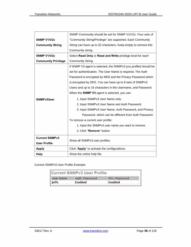
Current SNMPv3
User Profile Show all SNMPv3 user profiles.
Apply Click “Apply” to activate the configurations.
Help Show the online help file.
Current SNMPv3 User Profile Example:

Transition Networks SISTM1040-262D-LRT-B User Guide
33617 Rev. A www.transition.com Page 57 of 125
5.1.9.2 SNMP – Trap Setting
A trap manager is a management station that receives traps, the system alerts generated by
the switch. If no trap manager is defined, no traps will issued. Create a trap manager by
entering the IP address of the station and a community string. Selects the SNMP version and
click the Add button.
SNMP Trap Setting interface
The following table describes the labels in this screen.
Label Description
Server IP The server IP address to receive Traps.
Community Community for authentication.
Trap Version Trap Version supports V1 and V2c.
Add Click to add a Trap Server Profile.
Remove Click to remove an existing Trap Server Profile.
Help Show the online help file.
Current SNMPv3 User Profile Example:

Transition Networks SISTM1040-262D-LRT-B User Guide
33617 Rev. A www.transition.com Page 58 of 125
5.1.10 Traffic Prioritization Traffic Prioritization includes three modes: Port-based, 802.1p/COS, and TOS/DSCP. You can
use the traffic prioritization function to classify the traffic into four classes for different network
applications. The SISTM1040-262D-LRT-B supports four priority queues.
Polocy Setting interface
Label Description
QoS Mode
Port-base: the output priority is determined by ingress port.
COS only: the output priority is determined by COS only.
TOS only: the output priority is determined by TOS only.
COS first: the output priority is determined by COS and TOS, but
COS first.
TOS first: the output priority is determined by COS and TOS, but
TOS first.
Save changes by clicking Save at the Save Configuration menu option.
QoS policy
Use an 8,4,2,1 weight fair queuing scheme: the output queues will
follow 8:4:2:1 ratio to transmit packets from the highest to lowest
queue. For example: 8 high queue packets, 4 middle queue packets,
2 low queue packets, and the one lowest queue packets are
transmitted in one turn.
Use a strict priority scheme: always transmit the packets in the
higher queue first until the higher queue is empty.
Save changes by clicking Save at the Save Configuration menu option.
Help Show the online help file.
Apply Click “Apply” to activate the configuration settings.
Transition Networks SISTM1040-262D-LRT-B User Guide
33617 Rev. A www.transition.com Page 59 of 125
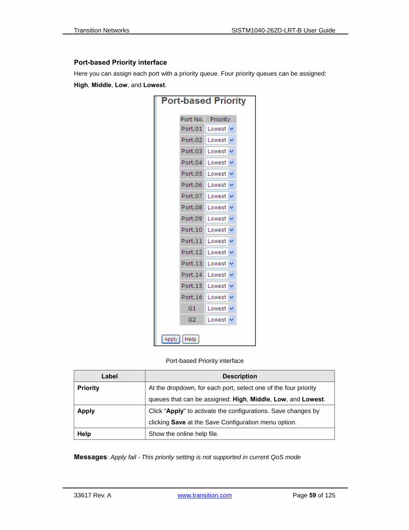
Port-based Priority interface
Here you can assign each port with a priority queue. Four priority queues can be assigned:
High, Middle, Low, and Lowest.
Port-based Priority interface
Label Description
Priority At the dropdown, for each port, select one of the four priority
queues that can be assigned: High, Middle, Low, and Lowest.
Apply Click “Apply” to activate the configurations. Save changes by
clicking Save at the Save Configuration menu option.
Help Show the online help file.
Messages: Apply fail - This priority setting is not supported in current QoS mode

Transition Networks SISTM1040-262D-LRT-B User Guide
33617 Rev. A www.transition.com Page 60 of 125
COS/802.1p interface
COS/802.1p interface
Label Description
COS/802.1p
COS (Class Of Service) is known as 802.1p. It describes that the
output priority of a packet is determined by the user priority field in a
802.1Q VLAN tag. The priority values 0 - 7 are supported. COS value
maps to four priority queues: High, Middle, Low, and Lowest.
COS Port Default When an ingress packet has no VLAN tag, a default priority value is
considered and determined by the ingress port.
Apply Click “Apply” to activate the configurations. Save changes by
clicking Save at the Save Configuration menu option.
Help Show help file.

Transition Networks SISTM1040-262D-LRT-B User Guide
33617 Rev. A www.transition.com Page 61 of 125
TOS/DSCP interface
TOS/DSCP interface
Label Description
TOS/DSCP
Priority
TOS (Type of Service) is a field in the IP header of a packet. This TOS
field is also used by Differentiated Services and is called the
Differentiated Services Code Point (DSCP). The output priority of a
packet can be determined by this field and priority values 0 - 63 are
supported. DSCP value maps to four priority queues: High, Middle,
Low, and Lowest.
Apply Click “Apply” to activate the configuration settings. Save changes by
clicking Save at the Save Configuration menu option.
Help Show the online help file.
Messages: Apply fail - Table full

Transition Networks SISTM1040-262D-LRT-B User Guide
33617 Rev. A www.transition.com Page 62 of 125
5.1.11 Multicast 5.1.11.1 IGMP Snooping
Internet Group Management Protocol (IGMP) is used by IP hosts to register their dynamic
multicast group membership. IGMP has 3 versions, IGMP v1, v2 and v3. Refer to RFC 1112,
2236 and 3376. IGMP Snooping improves the performance of networks that carry multicast
traffic. It provides the ability to prune multicast traffic so that it travels only to those end
destinations that require that traffic and reduces the amount of traffic on the Ethernet LAN.
IGMP Snooping interface
The following table describes the labels in this screen.
Label Description
IGMP Snooping Enable/Disable IGMP snooping.
IGMP Query Mode
Switch will be IGMP querier or not. There should exist one and
only one IGMP querier in an IGMP application. The "Auto" mode
means that the querier is the one with lower IP address.
IGMP Snooping Table Shows the current IP multicast list.
Apply Click “Apply” to activate the configurations.
Help Show the online help file.

Transition Networks SISTM1040-262D-LRT-B User Guide
33617 Rev. A www.transition.com Page 63 of 125
5.1.11.2 Static Group List
Multicasts are similar to broadcasts; they are sent to all end stations on a LAN or VLAN. Static
Group is the system by which end stations only receive multicast traffic if they register to join
specific multicast groups. With Static Group, network devices only forward multicast traffic to
the ports that are connected to registered end stations.
Multicast Filtering interface
The following table describes the labels in this screen.
Label Description
IP Address Assign a multicast group IP address in the range of 224.0.0.0 ~
239.255.255.255.
Member Ports Tick the check box beside the port number to include it as a
member port in the specific multicast group IP address.
Add Show current IP multicast list.
Delete Delete a selected entry from table.
Help Show the online help file.

Transition Networks SISTM1040-262D-LRT-B User Guide
33617 Rev. A www.transition.com Page 64 of 125
5.1.12 Security Five useful functions can enhance security of switch: IP Security, Port Security, MAC Blacklist,
and MAC address Aging and 802.1x protocol.
5.1.12.1 IP Security
IP Security can enable/disable remote management from WEB or Telnet or SNMP. Additionally,
IP security can restrict remote management to some specific IP addresses. Only these secure
IP addresses can manage this switch remotely.
IP Security interface
The following table describes the labels in this screen.
Label Description
IP Security Mode Enable/Disable the IP Security function globally.
Enable WEB Management Tick the check box to enable WEB Management.
Enable Telnet Management Tick the check box to enable Telnet Management.
Enable SNMP Management Tick the check box to enable MPSN Management.
Secure IP List Enter IP addresses; restrict remote management to some
specific IP addresses.
Apply Click “Apply” to activate the configurations.
Help Show help file.

Transition Networks SISTM1040-262D-LRT-B User Guide
33617 Rev. A www.transition.com Page 65 of 125
5.1.12.2 Port Security
Port security is used to add static MAC addresses to the hardware forwarding database. If port
security is enabled at Port Control page, only the frames with MAC addresses in this list will
be forwarded, otherwise they will be discarded.
Port Security interface
The following table describes the labels in this screen.
Label Description
MAC Address Input a MAC Address to a specific port.
Port No. Select a switch port from the dropdown.
Add Click to add an entry of MAC and port information to the list.
Delete Delete an existing entry from the list.
Help Show the online help file.
To add a static MAC address
1. In the MAC address box, enter a MAC address, e.g. "001122334455".
2. In the Port Number box, select a port number.
3. Click the Add button.
To delete a static MAC address
1. In the MAC address box, enter a MAC address.
2. Click the Delete button.

Transition Networks SISTM1040-262D-LRT-B User Guide
33617 Rev. A www.transition.com Page 66 of 125
5.1.12.3 MAC Blacklist
The MAC Blacklist can eliminate the traffic forwarding to specific MAC addresses in the list.
Any frames forwarding to MAC addresses in this list will be discarded. Thus the target device
will never receive any frame.
MAC Blacklist interface
The following table describes the labels in this screen.
Label Description
MAC Address Input MAC Address to add to the MAC Blacklist.
Add Add an entry to Blacklist table.
Delete Delete the entry from the list.
Help Show the online help file.
Messages: Apply fail - Entry existed and can't be modified

Transition Networks SISTM1040-262D-LRT-B User Guide
33617 Rev. A www.transition.com Page 67 of 125
5.1.12.4 802.1x
802.1x - Radius Server
IEEE 802.1x uses the physical access characteristics of IEEE802 LAN infrastructures to
provide an authenticated and authorized device attached to a LAN port. Refer to IEEE 802.1X
- Port Based Network Access Control for more information.
802.1x Radius Server interface
The following table describes the labels in this screen.
Label Description
Radius Server Setting
802.1X Protocol Enable or Disable RADIUS at the dropdown.
Radius Server IP The IP address of the authentication server.
Server Port Set the UDP port number used by the authentication server to
authenticate.
Accounting Port Set the UDP destination port for accounting requests to the
specified Radius Server.
Shared Key A key shared between this switch and authentication server.
NAS, Identifier A string used to identify this switch.

Transition Networks SISTM1040-262D-LRT-B User Guide
33617 Rev. A www.transition.com Page 68 of 125
Advanced Setting
Quiet Period
Set the time interval between authentication failure and the start
of a new authentication attempt. The Quiet Period is the period of
time during which it will not attempt to acquire a supplicant.
The default time is 60 seconds.
Tx Period
Set the time that the switch can wait for response to an EAP
request/identity frame from the client before resending the
request. The TX Period is the period of time to transmit an EAPOL
PDU. The default value is 30 seconds.
Supplicant Timeout
Set the period of time the switch waits for a supplicant response
to an EAP request. Supplicant Timeout: the timeout conditions in
the exchanges between the supplicant and authentication server.
The default value is 30 seconds.
Server Timeout
Set the period of time the switch waits for a Radius server
response to an authentication request. Server Timeout: is the
timeout condition in the exchanges between the authenticator and
authentication server. The default value is 30 seconds.
Max Requests
Set the maximum number of times to retry sending packets to the
supplicant. ReAuthMax is the number of reauthentication
attempts that are permitted before the specific port becomes
unauthorized. The default value is 2 times).
Re-Auth Period
Set the period of time after which clients connected must be
re-authenticated. Enter a nonzero number of seconds between
periodic reauthentication of the supplications. The default value is
3600 seconds).
Apply Click “Apply” to activate the configurations.
Help Show the online help file.
Transition Networks SISTM1040-262D-LRT-B User Guide
33617 Rev. A www.transition.com Page 69 of 125
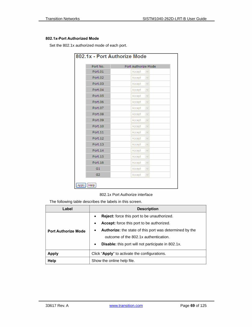
802.1x-Port Authorized Mode
Set the 802.1x authorized mode of each port.
802.1x Port Authorize interface
The following table describes the labels in this screen.
Label Description
Port Authorize Mode
Reject: force this port to be unauthorized.
Accept: force this port to be authorized.
Authorize: the state of this port was determined by the
outcome of the 802.1x authentication.
Disable: this port will not participate in 802.1x.
Apply Click “Apply” to activate the configurations.
Help Show the online help file.

Transition Networks SISTM1040-262D-LRT-B User Guide
33617 Rev. A www.transition.com Page 70 of 125
802.1x-Port Authorized State
Shows the 802.1x port authorized state.
802.1x Port Authorize State interface
5.1.13 Warning The Warning function is very important for managing the switch.
You can monitor the switch via Syslog, E-Mail, and Fault Relay from
a remote site. When events occur, the warning message is sent to
the configured E-Mail server, or the fault is relayed to the switch
panel.

Transition Networks SISTM1040-262D-LRT-B User Guide
33617 Rev. A www.transition.com Page 71 of 125
5.1.13.1 Fault Alarm
When any selected fault event occurs, the Fault LED on the switch panel lights and the electric
relay will signal at the same time.
Fault Alarm interface
The following table describes the labels in this screen.
Label Description
Power Failure Tick the PWR 1 or PWR 2 checkbox to enable monitoring this fault.
Port Link
Down/Broken
Tick the Port.01 to Port.18 checkbox to monitor for Port Link Down /
Port Link Broken fault on the port.
Apply Click “Apply” to activate the configurations.
Help Show the online help file.

Transition Networks SISTM1040-262D-LRT-B User Guide
33617 Rev. A www.transition.com Page 72 of 125
5.1.13.2 System Warning
System Warning suppors two warning modes: SYSLOG and E-MAIL. You can monitor the
switch via selected system events.
System Warning – SYSLOG Setting
The SYSLOG protocol is used to transmit event notification messages across networks.
Please refer to RFC 3164 - The BSD SYSLOG Protocol.
System Warning – SYSLOG Setting interface
The following table describes the labels in this screen.
Label Description
SYSLOG Mode
Disable: disable SYSLOG logging.
Client Only: log to local system.
Server Only: log to a remote SYSLOG server.
Both: log to both the local and remote servers.
SYSLOG Server IP
Address The remote SYSLOG Server IP address.
Apply Click “Apply” to activate the configurations.
Help Show the online help file.
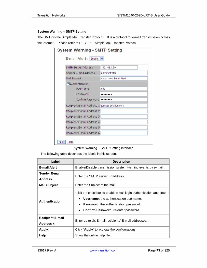
Transition Networks SISTM1040-262D-LRT-B User Guide
33617 Rev. A www.transition.com Page 73 of 125
System Warning – SMTP Setting
The SMTP is the Simple Mail Transfer Protocol. It is a protocol for e-mail transmission across
the Internet. Please refer to RFC 821 - Simple Mail Transfer Protocol.
System Warning – SMTP Setting interface
The following table describes the labels in this screen.
Label Description
E-mail Alert Enable/Disable transmission system warning events by e-mail.
Sender E-mail
Address Enter the SMTP server IP address.
Mail Subject Enter the Subject of the mail.
Authentication
Tick the checkbox to enable Email login authentication and enter:
Username: the authentication username.
Password: the authentication password.
Confirm Password: re-enter password.
Recipient E-mail
Address x Enter up to six E-mail recipients’ E-mail addresses.
Apply Click “Apply” to activate the configurations.
Help Show the online help file.

Transition Networks SISTM1040-262D-LRT-B User Guide
33617 Rev. A www.transition.com Page 74 of 125
System Warning – Event Selection
SYSLOG and SMTP are the two warning methods that supported by the system.
Check the corresponding box to enable the system event warning method you wish to choose.
Please note that the checkbox cannot be checked when SYSLOG or SMTP is disabled.
System Warning – Event Selection interface

Transition Networks SISTM1040-262D-LRT-B User Guide
33617 Rev. A www.transition.com Page 75 of 125
The following table describes the labels in this screen.
System Warning – Event Selection
Label Description
System Event
System Cold Start Alert when system restarts (cold restart).
Power Status Alert when a power up or down occurs.
SNMP Authentication Failure Alert when an SNMP authentication failure occurs.
Redundant Ring Topology
Change Alert when Redundant Ring topology changes.
Port Event
Port No.
SYSLOG Event
SMTP event
For Port.01 - Port.16 select:
Disable
Link Up
Link Down
Link Up & Link Down
Apply Click “Apply” to activate the configurations.
Help Show the online help file.

Transition Networks SISTM1040-262D-LRT-B User Guide
33617 Rev. A www.transition.com Page 76 of 125
5.1.14 Monitor and Diagnostics
5.1.14.1 MAC Address Table
Refer to IEEE 802.1 D Sections 7.9. The MAC Address Table (Filtering Database,)supports
queries by the Forwarding Process, as to whether a frame received by a given port with a
given destination MAC address is to be forwarded through a given potential transmission port.
MAC Address Table interface
The following table describes the labels in this screen.
Label Description
Port No : Show all MAC addresses mapping to the selected port.
Current MAC Address Displays the current MAC address for the port (if any).
Dynamic Address Count: Displays the number of dynamically assigned IP addresses.
Static Address Count: Displays the current number of statically assigned IP addresses.
Clear MAC Table Click to clear all MAC addresses in table.
Help Show the online help file.

Transition Networks SISTM1040-262D-LRT-B User Guide
33617 Rev. A www.transition.com Page 77 of 125
5.1.14.2 MAC Address Aging
You can set the MAC Address aging timer so that after the specified time has expired, the
unused MAC will be cleared from MAC table. The SISTM1040-262D-LRT-B also supports Auto
Flush MAC Address Table When ports Link Down.
MAC Address Aging interface
The following table describes the labels in this screen.
Label Description
MAC Address Table Aging
Time
Set the aging time for MAC table. The value is 0 - 3825
seconds. The default setting is 300 seconds.
Auto Flush MAC Address
Table When Ports Link
Down
Tick the checkbox to enable this function.
Apply Click “Apply” to activate the configurations.
Help Show the online help file.

Transition Networks SISTM1040-262D-LRT-B User Guide
33617 Rev. A www.transition.com Page 78 of 125
5.1.14.3 Port Statistics
Port statistics show several statistics counters for all ports.
Port Statistics interface
The following table describes the labels in this screen.
Label Description
Type Show port speed and media type (e.g., 100TX or 1GTX/SFP).
Link Show port link status (Up or Down).
State Show ports’ sttes (Enable or Disable).
TX Good Packet The number of good packets sent by this port.
TX Bad Packet The number of bad packets sent by this port.
RX Good Packet The number of good packets received by this port.
RX Bad Packet The number of bad packets received by this port.
TX Abort Packet The number of packets aborted by this port.
Packet Collision The number of times a collision was detected by this port.
Clear Clear all counters in this table.
Help Show the online help file.

Transition Networks SISTM1040-262D-LRT-B User Guide
33617 Rev. A www.transition.com Page 79 of 125
5.1.14.4 Port Monitoring
Port monitoring function supports TX (egress) only, RX (ingress) only, and both TX/RX
monitoring.
TX monitoring sends any data that egress out checked TX source ports to a selected TX
destination port as well.
RX monitoring sends any data that ingress in checked RX source ports out to a selected RX
destination port as well as sending the frame where it normally would have gone.
Note: to disable port monitoring, keep all source ports unchecked.
Port monitoring interface
Label Description
Destination Port The port(s) to receive a copied frame from Source port for monitoring
purpose. Tick the desired radio buttons.
Source Port The port(s) to be monitored. Tick the checkbox of for the ports whose
TX or RX is to be monitored.
TX The frames that come into switch port.
RX The frames that are received by switch port.
Apply Click “Apply” to activate the configurations.
Clear Click the button to clear all marked blank (disable the function).
Help Show the online help file.

Transition Networks SISTM1040-262D-LRT-B User Guide
33617 Rev. A www.transition.com Page 80 of 125
5.1.14.5 System Event Log
If the system log client is enabled, the system event logs will display in this table.
System event log interface
The following table describes the labels in this screen.
Label Description
Page Select the desired Log page at the dropdown.
Reload Click the button to get the newest event logs and refresh this page.
Clear Clear the log.
Help Show the online help file.
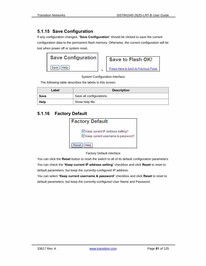
Transition Networks SISTM1040-262D-LRT-B User Guide
33617 Rev. A www.transition.com Page 81 of 125
5.1.15 Save Configuration If any configuration changed, “Save Configuration” should be clicked to save the current
configuration data to the permanent flash memory. Otherwise, the current configuration will be
lost when power off or system reset.
>
System Configuration interface
The following table describes the labels in this screen.
Label Description
Save Save all configurations.
Help Show help file.
5.1.16 Factory Default
Factory Default interface
You can click the Reset button to reset the switch to all of its default configuration parameters.
You can check the “Keep current IP address setting” checkbox and click Reset to reset to
default parameters, but keep the currently-configured IP address.
You can select “Keep current username & password” checkbox and click Reset to reset to
default parameters, but keep the currently-configured User Name and Password.

Transition Networks SISTM1040-262D-LRT-B User Guide
33617 Rev. A www.transition.com Page 82 of 125
5.1.17 System Reboot
System Reboot interface
You can click the Reboot button to restart the switch.
Messages: Rebooting ... After several seconds, reconnect the system.

Transition Networks SISTM1040-262D-LRT-B User Guide
33617 Rev. A www.transition.com Page 83 of 125
6. Command Line Interface Management
6.1 About CLI Management Besides Web-based management, the SISTM1040-262D-LRT-B also supports CLI
management. You can use a console or Telnet to manage the switch via the CLI.
CLI Management by RS-232 Serial Console (9600, 8, none, 1, none)
Before configuring by RS-232 serial console, use an RJ45 to DB9-F cable to connect the
RS-232 Console port on the Switch to the COM Port on your PC.
Follow the steps below to access the console via RS-232 serial cable.
Step 1. From the Windows desktop, click on Start -> Programs -> Accessories ->
Communications -> Hyper Terminal.
Step 2. Input a name for new connection.

Transition Networks SISTM1040-262D-LRT-B User Guide
33617 Rev. A www.transition.com Page 84 of 125
Step 3. Select to use COM port number.
Step 4. The COM port properties setting, 9600 for Bits per second, 8 for Data bits, None for
Parity, 1 for Stop bits and none for Flow control.
Step 5. The Console login screen displays. Use the keyboard to enter the Username and
Password (the same with the password for Web browser), then press “Enter”.
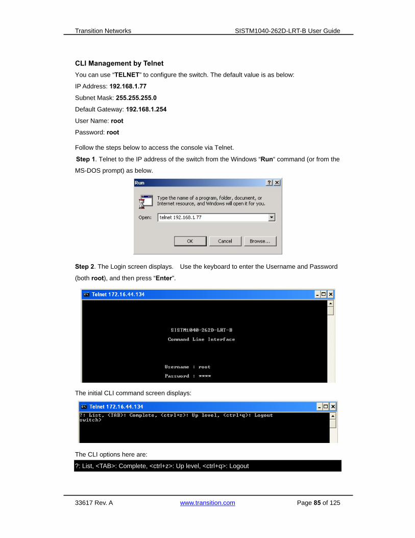
Transition Networks SISTM1040-262D-LRT-B User Guide
33617 Rev. A www.transition.com Page 85 of 125
CLI Management by Telnet
You can use “TELNET” to configure the switch. The default value is as below:
IP Address: 192.168.1.77
Subnet Mask: 255.255.255.0
Default Gateway: 192.168.1.254
User Name: root
Password: root
Follow the steps below to access the console via Telnet.
Step 1. Telnet to the IP address of the switch from the Windows “Run“ command (or from the
MS-DOS prompt) as below.
Step 2. The Login screen displays. Use the keyboard to enter the Username and Password
(both root), and then press “Enter”.
The initial CLI command screen displays:
The CLI options here are:
?: List, <TAB>: Complete, <ctrl+z>: Up level, <ctrl+q>: Logout

Transition Networks SISTM1040-262D-LRT-B User Guide
33617 Rev. A www.transition.com Page 86 of 125
Step 3. Use the ? command to list the varous available commands.
show commands:
Configure commands

Transition Networks SISTM1040-262D-LRT-B User Guide
33617 Rev. A www.transition.com Page 87 of 125
Command Levels
Mode Access Method Prompt Exit Method About This Mode
User EXEC Begin a session with
your switch. switch>
Enter logout or
quit.
The user commands
available at this level are a
subset of those available at
the privileged level. Use this
mode to
• Enter menu mode.
• Display system information.
Privileged
EXEC
Enter the enable
command while in user
EXEC mode.
switch# Enter disable to
exit.
The privileged commands are
more advanced
Use this mode to
• Display advance function
status
• save configurations
Global
configuration
Enter the configure
command while in
privileged EXEC mode.
switch(confi
g)#
To exit to
privileged
EXEC mode,
enter exit or end
Use this mode to configure
parameters that apply to your
Switch as a whole.
VLAN
database
Enter the vlan database
command while in
privileged
EXEC mode.
switch(vlan)
#
To exit to user
EXEC mode,
enter exit.
Use this mode to configure
VLAN-specific parameters.
Interface
configuration
Enter the interface
command (with a
specific interface)while
in global configuration
mode
switch(confi
g-if)#
To exit to global
configuration
mode,
enter exit.
To exit privileged
EXEC mode or
end.
Use this mode to configure
parameters for the switch and
Ethernet ports.

Transition Networks SISTM1040-262D-LRT-B User Guide
33617 Rev. A www.transition.com Page 88 of 125
Symbol of Command Level
Mode Symbol for Command Level
User EXEC E
Privileged EXEC P
Global configuration G
VLAN database V
Interface configuration I
6.2 System Commands
Command Level Description Example
show config E Show switch
configuration
switch>show config
show terminal P Show console
information
switch#show terminal
write memory P Save your
configuration into
permanent memory
(flash rom)
switch#write memory
system name
[System Name]
G Configure system
name
switch(config)#system name xxx
system location
[System Location]
G Set switch system
location string
switch(config)#system location xxx
system description
[System Description]
G Set switch system
description string
switch(config)#system description
xxx
system contact
[System Contact]
G Set switch system
contact window string
switch(config)#system contact xxx
show system-info E Show system
information
switch>show system-info
ip address
[Ip-address]
[Subnet-mask]
[Gateway]
G Configure the IP
address of switch
switch(config)#ip address
192.168.1.1 255.255.255.0
192.168.1.254
ip dhcp
G Enable DHCP client
function of switch
switch(config)#ip dhcp
show ip P Show IP information of
switch
switch#show ip

Transition Networks SISTM1040-262D-LRT-B User Guide
33617 Rev. A www.transition.com Page 89 of 125
no ip dhcp
G Disable DHCP client
function of switch
switch(config)#no ip dhcp
reload G Halt and perform a
cold restart
switch(config)#reload
default G Restore to default Switch(config)#default
admin username
[Username]
G Changes a login
username.
(maximum 10 words)
switch(config)#admin username
xxxxxx
admin password
[Password]
G Specifies a password
(maximum 10 words)
switch(config)#admin password
xxxxxx
show admin P Show administrator
information
switch#show admin
dhcpserver enable G Enable DHCP Server switch(config)#dhcpserver enable
dhcpserver lowip
[Low IP]
G Configure low IP
address for IP pool
switch(config)# dhcpserver lowip
192.168.1.1
dhcpserver highip
[High IP]
G Configure high IP
address for IP pool
switch(config)# dhcpserver highip
192.168.1.50
dhcpserver subnetmask
[Subnet mask]
G Configure subnet
mask for DHCP clients
switch(config)#dhcpserver
subnetmask 255.255.255.0
dhcpserver gateway
[Gateway]
G Configure gateway for
DHCP clients
switch(config)#dhcpserver gateway
192.168.1.254
dhcpserver dnsip
[DNS IP]
G Configure DNS IP for
DHCP clients
switch(config)# dhcpserver dnsip
192.168.1.1
dhcpserver leasetime
[Hours]
G Configure lease time
(in hour)
switch(config)#dhcpserver
leasetime 1
dhcpserver ipbinding
[IP address]
I Set static IP for DHCP
clients by port
switch(config)#interface
fastEthernet 2
switch(config-if)#dhcpserver
ipbinding 192.168.1.1
show dhcpserver
configuration
P Show configuration of
DHCP server
switch#show dhcpserver
configuration
show dhcpserver clients P Show client entries of
DHCP server
switch#show dhcpserver clinets
show dhcpserver
ip-binding
P Show IP-Binding
information of DHCP
server
switch#show dhcpserver ip-binding
no dhcpserver G Disable DHCP server switch(config)#no dhcpserver

Transition Networks SISTM1040-262D-LRT-B User Guide
33617 Rev. A www.transition.com Page 90 of 125
function
security enable G Enable IP security
function
switch(config)#security enable
security http G Enable IP security of
HTTP server
switch(config)#security http
security telnet G Enable IP security of
telnet server
switch(config)#security telnet
security ip
[Index(1..10)] [IP
Address]
G Set the IP security list switch(config)#security ip 1
192.168.1.55
show security P Show the information
of IP security
switch#show security
no security G Disable IP security
function
switch(config)#no security
no security http G Disable IP security of
HTTP server
switch(config)#no security http
no security telnet G Disable IP security of
telnet server
switch(config)#no security telnet
6.3 Port Commands
Command Level Description Example
interface fastEthernet
[Portid]
G Choose the port for
modification.
switch(config)#interface
fastEthernet 2
duplex
[full | half]
I Use the duplex
configuration
command to specify
the duplex mode of
operation for Fast
Ethernet.
switch(config)#interface
fastEthernet 2
switch(config-if)#duplex full
speed
[10|100|1000|auto]
I Use the speed
configuration
command to specify
the speed mode of
operation for Fast
Ethernet., the speed
can’t be set to 1000 if
switch(config)#interface
fastEthernet 2
switch(config-if)#speed 100

Transition Networks SISTM1040-262D-LRT-B User Guide
33617 Rev. A www.transition.com Page 91 of 125
the port isn’t a gigabit
port..
flowcontrol mode
[Symmetric|Asymmetric]
I Use the flowcontrol
configuration
command on Ethernet
ports to control traffic
rates during
congestion.
switch(config)#interface
fastEthernet 2
switch(config-if)#flowcontrol mode
Asymmetric
no flowcontrol I Disable flow control of
interface
switch(config-if)#no flowcontrol
security enable I Enable security of
interface
switch(config)#interface
fastEthernet 2
switch(config-if)#security enable
no security I Disable security of
interface
switch(config)#interface
fastEthernet 2
switch(config-if)#no security
bandwidth type all I Set interface ingress
limit frame type to
“accept all frame”
switch(config)#interface
fastEthernet 2
switch(config-if)#bandwidth type all
bandwidth type
broadcast-multicast-floo
ded-unicast
I Set interface ingress
limit frame type to
“accept broadcast,
multicast, and flooded
unicast frame”
switch(config)#interface
fastEthernet 2
switch(config-if)#bandwidth type
broadcast-multicast-flooded-unicast
bandwidth type
broadcast-multicast
I Set interface ingress
limit frame type to
“accept broadcast and
multicast frame”
switch(config)#interface
fastEthernet 2
switch(config-if)#bandwidth type
broadcast-multicast
bandwidth type
broadcast-only
I Set interface ingress
limit frame type to
“only accept
broadcast frame”
switch(config)#interface
fastEthernet 2
switch(config-if)#bandwidth type
broadcast-only
bandwidth in
[Value]
I Set interface input
bandwidth. Rate
Range is from 100
kbps to 102400 kbps
switch(config)#interface
fastEthernet 2
switch(config-if)#bandwidth in 100

Transition Networks SISTM1040-262D-LRT-B User Guide
33617 Rev. A www.transition.com Page 92 of 125
or to 256000 kbps for
giga ports,
and zero means no
limit.
bandwidth out
[Value]
I Set interface output
bandwidth. Rate
Range is from 100
kbps to 102400 kbps
or to 256000 kbps for
giga ports,
and zero means no
limit.
switch(config)#interface
fastEthernet 2
switch(config-if)#bandwidth out 100
show bandwidth I Show interfaces
bandwidth control
switch(config)#interface
fastEthernet 2
switch(config-if)#show bandwidth
state
[Enable | Disable]
I Use the state interface
configuration
command to specify
the state mode of
operation for Ethernet
ports. Use the
disable form of this
command to disable
the port.
switch(config)#interface
fastEthernet 2
switch(config-if)#state Disable
show interface
configuration
I show interface
configuration status
switch(config)#interface
fastEthernet 2
switch(config-if)#show interface
configuration
show interface status I show interface actual
status
switch(config)#interface
fastEthernet 2
switch(config-if)#show interface
status
show interface
accounting
I show interface
statistic counter
switch(config)#interface
fastEthernet 2
switch(config-if)#show interface
accounting
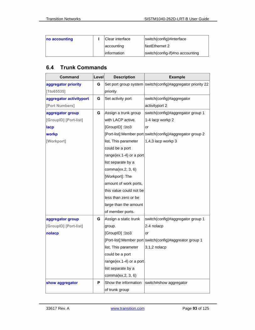
Transition Networks SISTM1040-262D-LRT-B User Guide
33617 Rev. A www.transition.com Page 93 of 125
no accounting I Clear interface
accounting
information
switch(config)#interface
fastEthernet 2
switch(config-if)#no accounting
6.4 Trunk Commands
Command Level Description Example
aggregator priority
[1to65535]
G Set port group system
priority
switch(config)#aggregator priority 22
aggregator activityport
[Port Numbers]
G Set activity port switch(config)#aggregator
activityport 2
aggregator group
[GroupID] [Port-list]
lacp
workp
[Workport]
G Assign a trunk group
with LACP active.
[GroupID] :1to3
[Port-list]:Member port
list, This parameter
could be a port
range(ex.1-4) or a port
list separate by a
comma(ex.2, 3, 6)
[Workport]: The
amount of work ports,
this value could not be
less than zero or be
large than the amount
of member ports.
switch(config)#aggregator group 1
1-4 lacp workp 2
or
switch(config)#aggregator group 2
1,4,3 lacp workp 3
aggregator group
[GroupID] [Port-list]
nolacp
G Assign a static trunk
group.
[GroupID] :1to3
[Port-list]:Member port
list, This parameter
could be a port
range(ex.1-4) or a port
list separate by a
comma(ex.2, 3, 6)
switch(config)#aggregator group 1
2-4 nolacp
or
switch(config)#aggreator group 1
3,1,2 nolacp
show aggregator P Show the information
of trunk group
switch#show aggregator

Transition Networks SISTM1040-262D-LRT-B User Guide
33617 Rev. A www.transition.com Page 94 of 125
no aggregator lacp
[GroupID]
G Disable the LACP
function of trunk group
switch(config)#no aggreator lacp 1
no aggregator group
[GroupID]
G Remove a trunk group switch(config)#no aggreator group 2
6.5 VLAN Commands Command Level Description Example
vlan database P Enter VLAN configure
mode
switch#vlan database
vlan
[8021q | gvrp]
V To set switch VLAN
mode.
switch(vlan)# vlanmode 802.1q
or
switch(vlan)# vlanmode gvrp
no vlan
[VID]
V Disable vlan group(by
VID)
switch(vlan)#no vlan 2
no gvrp V Disable GVRP switch(vlan)#no gvrp
IEEE 802.1Q VLAN
vlan 8021q port
[PortNumber]
access-link untag
[UntaggedVID]
V Assign a access link
for VLAN by port, if the
port belong to a trunk
group, this command
can’t be applied.
switch(vlan)#vlan 802.1q port 3
access-link untag 33
vlan 8021q port
[PortNumber]
trunk-link tag
[TaggedVID List]
V Assign a trunk link for
VLAN by port, if the
port belong to a trunk
group, this command
can’t be applied.
switch(vlan)#vlan 8021q port 3
trunk-link tag 2,3,6,99
or
switch(vlan)#vlan 8021q port 3
trunk-link tag 3-20
vlan 8021q port
[PortNumber]
hybrid-link untag
[UntaggedVID]
tag
[TaggedVID List]
V Assign a hybrid link for
VLAN by port, if the
port belong to a trunk
group, this command
can’t be applied.
switch(vlan)# vlan 8021q port 3
hybrid-link untag 4 tag 3,6,8
or
switch(vlan)# vlan 8021q port 3
hybrid-link untag 5 tag 6-8
vlan 8021q aggreator
[TrunkID]
access-link untag
[UntaggedVID]
V Assign a access link
for VLAN by trunk
group
switch(vlan)#vlan 8021q aggreator 3
access-link untag 33
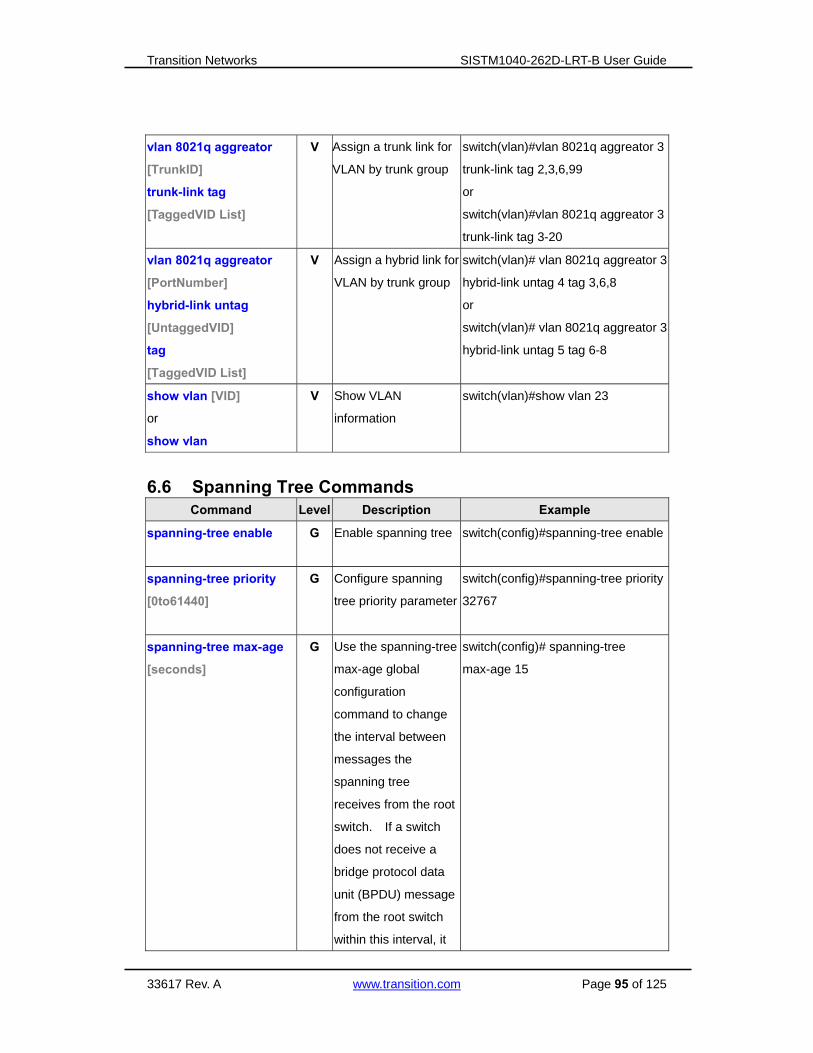
Transition Networks SISTM1040-262D-LRT-B User Guide
33617 Rev. A www.transition.com Page 95 of 125
vlan 8021q aggreator
[TrunkID]
trunk-link tag
[TaggedVID List]
V Assign a trunk link for
VLAN by trunk group
switch(vlan)#vlan 8021q aggreator 3
trunk-link tag 2,3,6,99
or
switch(vlan)#vlan 8021q aggreator 3
trunk-link tag 3-20
vlan 8021q aggreator
[PortNumber]
hybrid-link untag
[UntaggedVID]
tag
[TaggedVID List]
V Assign a hybrid link for
VLAN by trunk group
switch(vlan)# vlan 8021q aggreator 3
hybrid-link untag 4 tag 3,6,8
or
switch(vlan)# vlan 8021q aggreator 3
hybrid-link untag 5 tag 6-8
show vlan [VID]
or
show vlan
V Show VLAN
information
switch(vlan)#show vlan 23
6.6 Spanning Tree Commands Command Level Description Example
spanning-tree enable G
Enable spanning tree switch(config)#spanning-tree enable
spanning-tree priority
[0to61440]
G Configure spanning
tree priority parameter
switch(config)#spanning-tree priority
32767
spanning-tree max-age
[seconds]
G Use the spanning-tree
max-age global
configuration
command to change
the interval between
messages the
spanning tree
receives from the root
switch. If a switch
does not receive a
bridge protocol data
unit (BPDU) message
from the root switch
within this interval, it
switch(config)# spanning-tree
max-age 15
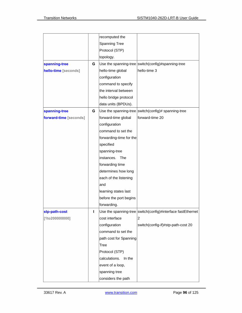
Transition Networks SISTM1040-262D-LRT-B User Guide
33617 Rev. A www.transition.com Page 96 of 125
recomputed the
Spanning Tree
Protocol (STP)
topology.
spanning-tree
hello-time [seconds]
G Use the spanning-tree
hello-time global
configuration
command to specify
the interval between
hello bridge protocol
data units (BPDUs).
switch(config)#spanning-tree
hello-time 3
spanning-tree
forward-time [seconds]
G Use the spanning-tree
forward-time global
configuration
command to set the
forwarding-time for the
specified
spanning-tree
instances. The
forwarding time
determines how long
each of the listening
and
learning states last
before the port begins
forwarding.
switch(config)# spanning-tree
forward-time 20
stp-path-cost
[1to200000000]
I Use the spanning-tree
cost interface
configuration
command to set the
path cost for Spanning
Tree
Protocol (STP)
calculations. In the
event of a loop,
spanning tree
considers the path
switch(config)#interface fastEthernet
2
switch(config-if)#stp-path-cost 20

Transition Networks SISTM1040-262D-LRT-B User Guide
33617 Rev. A www.transition.com Page 97 of 125
cost when selecting
an interface to place
into the forwarding
state.
stp-path-priority
[Port Priority]
I Use the spanning-tree
port-priority interface
configuration
command to configure
a port priority that
is used when two
switches tie for
position as the root
switch.
switch(config)#interface fastEthernet
2
switch(config-if)# stp-path-priority
127
stp-admin-p2p
[Auto|True|False]
I Admin P2P of STP
priority on this
interface.
switch(config)#interface fastEthernet
2
switch(config-if)# stp-admin-p2p
Auto
stp-admin-edge
[True|False]
I Admin Edge of STP
priority on this
interface.
switch(config)#interface fastEthernet
2
switch(config-if)# stp-admin-edge
True
stp-admin-non-stp
[True|False]
I Admin NonSTP of
STP priority on this
interface.
switch(config)#interface fastEthernet
2
switch(config-if)# stp-admin-non-stp
False
show spanning-tree
E Display a summary of
the spanning-tree
states.
switch>show spanning-tree
no spanning-tree
G Disable spanning-tree. switch(config)#no spanning-tree

Transition Networks SISTM1040-262D-LRT-B User Guide
33617 Rev. A www.transition.com Page 98 of 125
6.7 QoS Commands
Command Level Description Example
qos policy
[weighted-fair|strict]
G Select QOS policy
scheduling
switch(config)#qos policy
weighted-fair
qos prioritytype
[port-based|cos-only|tos
-only|cos-first|tos-first]
G Setting of QOS
priority type
switch(config)#qos prioritytype
qos priority portbased
[Port]
[lowest|low|middle|high]
G Configure Port-based
Priority
switch(config)#qos priority portbased
1 low
qos priority cos
[Priority][lowest|low|mid
dle|high]
G Configure COS
Priority
switch(config)#qos priority cos 22
middle
qos priority tos
[Priority][lowest|low|mid
dle|high]
G Configure TOS
Priority
switch(config)#qos priority tos 3 high
show qos P Display the
information of QoS
configuration
switch>show qos
no qos G Disable QoS function switch(config)#no qos
6.8 IGMP Sommands
Command Level Description Example
igmp enable G Enable IGMP
snooping function
switch(config)#igmp enable
Igmp-query auto G Set IGMP query to
auto mode
switch(config)#Igmp-query auto
Igmp-query force G Set IGMP query to
force mode
switch(config)#Igmp-query force
show igmp
configuration
P Displays the details of
an IGMP
configuration.
switch#show igmp configuration
show igmp multi P Displays the details of
an IGMP snooping
entries.
switch#show igmp multi
no igmp G Disable IGMP switch(config)#no igmp

Transition Networks SISTM1040-262D-LRT-B User Guide
33617 Rev. A www.transition.com Page 99 of 125
snooping function
no igmp-query G Disable IGMP query switch#no igmp-query
6.9 MAC/Filter Table Sommands
Command Level Description Example
mac-address-table static
hwaddr
[MAC]
I Configure MAC
address table of
interface (static).
switch(config)#interface fastEthernet
2
switch(config-if)#mac-address-table
static hwaddr 000012345678
mac-address-table filter
hwaddr
[MAC]
G Configure MAC
address table(filter)
switch(config)#mac-address-table
filter hwaddr 000012348678
show mac-address-table P Show all MAC
address table
switch#show mac-address-table
show mac-address-table
static
P Show static MAC
address table
switch#show mac-address-table
static
show mac-address-table
filter
P Show filter MAC
address table.
switch#show mac-address-table filter
no mac-address-table
static hwaddr
[MAC]
I Remove an entry of
MAC address table of
interface (static)
switch(config)#interface fastEthernet
2
switch(config-if)#no
mac-address-table static hwaddr
000012345678
no mac-address-table
filter hwaddr
[MAC]
G Remove an entry of
MAC address table
(filter)
switch(config)#no mac-address-table
filter hwaddr 000012348678
no mac-address-table G Remove dynamic
entry of MAC address
table
switch(config)#no mac-address-table

Transition Networks SISTM1040-262D-LRT-B User Guide
33617 Rev. A www.transition.com Page 100 of 125
6.10 SNMP Commands Command Level Description Example
snmp agent-mode
[v1v2c | v3]
G Select the agent mode
of SNMP
switch(config)#snmp agent-mode
v1v2c
snmp-server host
[IP address]
community
[Community-string]
trap-version
[v1|v2c]
G Configure SNMP
server host
information and
community string
switch(config)#snmp-server host
192.168.10.50 community public
trap-version v1
(remove)
Switch(config)#
no snmp-server host
192.168.10.50
snmp
community-strings
[Community-string]
right
[RO|RW]
G Configure the
community string right
switch(config)#snmp
community-strings public right RO
or
switch(config)#snmp
community-strings public right RW
snmp snmpv3-user
[User Name]
password
[Authentication
Password] [Privacy
Password]
G Configure the
userprofile for
SNMPV3 agent.
Privacy password
could be empty.
switch(config)#snmp snmpv3-user
test01 password AuthPW PrivPW
show snmp P Show SNMP
configuration
switch#show snmp
show snmp-server P Show specified trap
server information
switch#show snmp-server
no snmp
community-strings
[Community]
G Remove the specified
community.
switch(config)#no snmp
community-strings public
no snmp snmpv3-user
[User Name]
password
[Authentication
Password] [Privacy
Password]
G Remove specified
user of SNMPv3
agent. Privacy
password could be
empty.
switch(config)# no snmp
snmpv3-user test01 password
AuthPW PrivPW
no snmp-server host
[Host-address]
G Remove the SNMP
server host.
switch(config)#no snmp-server
192.168.10.50

Transition Networks SISTM1040-262D-LRT-B User Guide
33617 Rev. A www.transition.com Page 101 of 125
6.11 Port Mirroring Commands
Command Level Description Example
monitor rx G Set RX destination
port of monitor
function
switch(config)#monitor rx
monitor tx G Set TX destination
port of monitor
function
switch(config)#monitor tx
show monitor P Show port monitor
information
switch#show monitor
monitor
[RX|TX|Both]
I Configure source port
of monitor function
switch(config)#interface fastEthernet
2
switch(config-if)#monitor RX
show monitor I Show port monitor
information
switch(config)#interface fastEthernet
2
switch(config-if)#show monitor
no monitor I Disable source port of
monitor function
switch(config)#interface fastEthernet
2
switch(config-if)#no monitor
6.12 802.1x Commands Command Level Description Example
8021x enable G
Use the 802.1x global
configuration
command to enable
802.1x protocols.
switch(config)# 8021x enable
8021x system radiousip
[IP address]
G Use the 802.1x
system radious IP
global configuration
command to change
the radious server IP.
switch(config)# 8021x system
radiousip 192.168.1.1
8021x system serverport
[port ID]
G Use the 802.1x
system server port
global configuration
command to change
the radious server port
switch(config)# 8021x system
serverport 1815

Transition Networks SISTM1040-262D-LRT-B User Guide
33617 Rev. A www.transition.com Page 102 of 125
8021x system
accountport
[port ID]
G Use the 802.1x
system account port
global configuration
command to change
the accounting port
switch(config)# 8021x system
accountport 1816
8021x system sharekey
[ID]
G Use the 802.1x
system share key
global configuration
command to change
the shared key value.
switch(config)# 8021x system
sharekey 123456
8021x system nasid
[words]
G Use the 802.1x
system nasid global
configuration
command to change
the NAS ID
switch(config)# 8021x system nasid
test1
8021x misc quietperiod
[sec.]
G Use the 802.1x misc
quiet period global
configuration
command to specify
the quiet period value
of the switch.
switch(config)# 8021x misc
quietperiod 10
8021x misc txperiod
[sec.]
G Use the 802.1x misc
TX period global
configuration
command to set the
TX period.
switch(config)# 8021x misc txperiod
5
8021x misc
supportimeout [sec.]
G Use the 802.1x misc
supp timeout global
configuration
command to set the
supplicant timeout.
switch(config)# 8021x misc
supportimeout 20
8021x misc
servertimeout [sec.]
G Use the 802.1x misc
server timeout global
configuration
command to set the
server timeout.
switch(config)#8021x misc
servertimeout 20

Transition Networks SISTM1040-262D-LRT-B User Guide
33617 Rev. A www.transition.com Page 103 of 125
8021x misc maxrequest
[number]
G Use the 802.1x misc
max request global
configuration
command to set the
MAX requests.
switch(config)# 8021x misc
maxrequest 3
8021x misc
reauthperiod [sec.]
G Use the 802.1x misc
reauth period global
configuration
command to set the
reauth period.
switch(config)# 8021x misc
reauthperiod 3000
8021x portstate
[disable | reject | accept |
authorize]
I Use the 802.1x port
state interface
configuration
command to set the
state of the selected
port.
switch(config)#interface fastethernet
3
switch(config-if)#8021x portstate
accept
show 8021x E Display a summary of
the 802.1x properties
and also the port
sates.
switch>show 8021x
no 8021x G Disable 802.1x
function
switch(config)#no 8021x
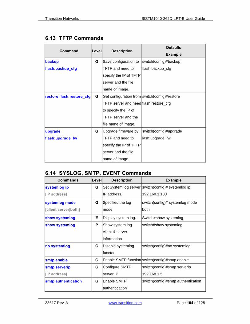
Transition Networks SISTM1040-262D-LRT-B User Guide
33617 Rev. A www.transition.com Page 104 of 125
6.13 TFTP Commands
Command Level Description Defaults
Example
backup
flash:backup_cfg
G Save configuration to
TFTP and need to
specify the IP of TFTP
server and the file
name of image.
switch(config)#backup
flash:backup_cfg
restore flash:restore_cfg G Get configuration from
TFTP server and need
to specify the IP of
TFTP server and the
file name of image.
switch(config)#restore
flash:restore_cfg
upgrade
flash:upgrade_fw
G Upgrade firmware by
TFTP and need to
specify the IP of TFTP
server and the file
name of image.
switch(config)#upgrade
lash:upgrade_fw
6.14 SYSLOG, SMTP, EVENT Commands Commands Level Description Example
systemlog ip
[IP address]
G Set System log server
IP address.
switch(config)# systemlog ip
192.168.1.100
systemlog mode
[client|server|both]
G Specified the log
mode
switch(config)# systemlog mode
both
show systemlog E Display system log. Switch>show systemlog
show systemlog P Show system log
client & server
information
switch#show systemlog
no systemlog G Disable systemlog
functon
switch(config)#no systemlog
smtp enable G Enable SMTP function switch(config)#smtp enable
smtp serverip
[IP address]
G Configure SMTP
server IP
switch(config)#smtp serverip
192.168.1.5
smtp authentication G Enable SMTP
authentication
switch(config)#smtp authentication

Transition Networks SISTM1040-262D-LRT-B User Guide
33617 Rev. A www.transition.com Page 105 of 125
smtp account
[account]
G Configure
authentication
account
switch(config)#smtp account User
smtp password
[password]
G Configure
authentication
password
switch(config)#smtp password
smtp rcptemail
[Index] [Email address]
G Configure Rcpt e-mail
Address
switch(config)#smtp rcptemail 1
show smtp P Show the information
of SMTP
switch#show smtp
no smtp G Disable SMTP
function
switch(config)#no smtp
event device-cold-start
[Systemlog|SMTP|Both]
G Set cold start event
type
switch(config)#event
device-cold-start both
event
authentication-failure
[Systemlog|SMTP|Both]
G Set Authentication
failure event type
switch(config)#event
authentication-failure both
event
O-Ring-topology-change
[Systemlog|SMTP|Both]
G Set s ring topology
changed event type
switch(config)#event
ring-topology-change both
event systemlog
[Link-UP|Link-Down|Bot
h]
I Set port event for
system log
switch(config)#interface fastethernet
3
switch(config-if)#event systemlog
both
event smtp
[Link-UP|Link-Down|Bot
h]
I Set port event for
SMTP
switch(config)#interface fastethernet
3
switch(config-if)#event smtp both
show event P Show event selection switch#show event
no event
device-cold-start
G Disable cold start
event type
switch(config)#no event
device-cold-start
no event
authentication-failure
G Disable Authentication
failure event typ
switch(config)#no event
authentication-failure
no event
O-Ring-topology-change
G Disable O-Ring
topology changed
event type
switch(config)#no event
ring-topology-change
no event systemlog I Disable port event for
system log
switch(config)#interface fastethernet
3
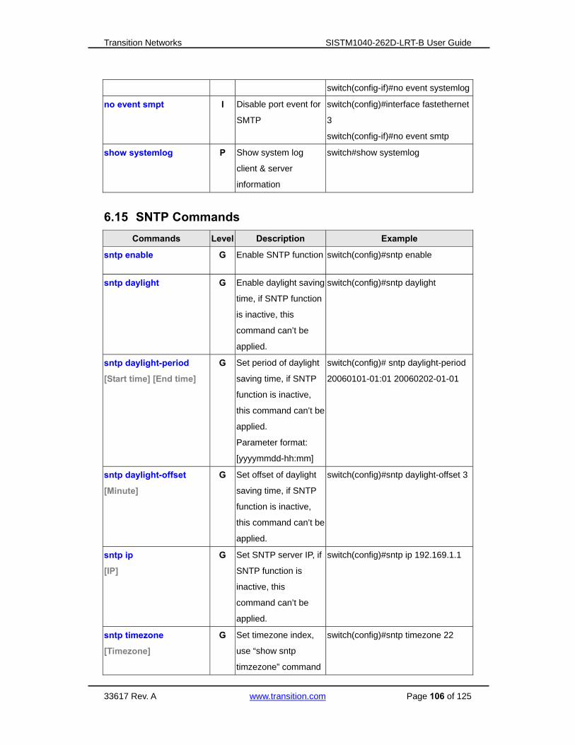
Transition Networks SISTM1040-262D-LRT-B User Guide
33617 Rev. A www.transition.com Page 106 of 125
switch(config-if)#no event systemlog
no event smpt I Disable port event for
SMTP
switch(config)#interface fastethernet
3
switch(config-if)#no event smtp
show systemlog P Show system log
client & server
information
switch#show systemlog
6.15 SNTP Commands
Commands Level Description Example
sntp enable G Enable SNTP function switch(config)#sntp enable
sntp daylight G Enable daylight saving
time, if SNTP function
is inactive, this
command can’t be
applied.
switch(config)#sntp daylight
sntp daylight-period
[Start time] [End time]
G Set period of daylight
saving time, if SNTP
function is inactive,
this command can’t be
applied.
Parameter format:
[yyyymmdd-hh:mm]
switch(config)# sntp daylight-period
20060101-01:01 20060202-01-01
sntp daylight-offset
[Minute]
G Set offset of daylight
saving time, if SNTP
function is inactive,
this command can’t be
applied.
switch(config)#sntp daylight-offset 3
sntp ip
[IP]
G Set SNTP server IP, if
SNTP function is
inactive, this
command can’t be
applied.
switch(config)#sntp ip 192.169.1.1
sntp timezone
[Timezone]
G Set timezone index,
use “show sntp
timzezone” command
switch(config)#sntp timezone 22

Transition Networks SISTM1040-262D-LRT-B User Guide
33617 Rev. A www.transition.com Page 107 of 125
to get more
information of index
number
show sntp P Show SNTP
information
switch#show sntp
show sntp timezone P Show index number of
time zone list
switch#show sntp timezone
no sntp G Disable SNTP
function
switch(config)#no sntp
no sntp daylight G Disable daylight
saving time
switch(config)#no sntp daylight
6.16 Ring Commands
Commands Level Description Example
Ring enable G Enable O-Ring switch(config)# ring enable
Ring master G Enable ring master switch(config)# ring master
Ring couplering G Enable couple ring switch(config)# ring couplering
Ring dualhoming G Enable dual homing switch(config)# ring dualhoming
Ring ringport
[1st Ring Port] [2nd Ring
Port]
G Configure 1st/2nd
Ring Port
switch(config)# ring ringport 7 8
Ring couplingport
[Coupling Port]
G Configure Coupling
Port
switch(config)# ring couplingport 1
Ring controlport
[Control Port]
G Configure Control Port switch(config)# ring controlport 2
Ring homingport
[Dual Homing Port]
G Configure Dual
Homing Port
switch(config)# ring homingport 3
show Ring P Show the information
of O-Ring
switch#show ring
no Ring G Disable O-Ring switch(config)#no ring
no Ring master G Disable ring master switch(config)# no ring master
no Ring couplering G Disable couple ring switch(config)# no ring couplering
no Ring dualhoming G Disable dual homing switch(config)# no ring dualhoming

Transition Networks SISTM1040-262D-LRT-B User Guide
33617 Rev. A www.transition.com Page 108 of 125
7. Technical Specifications
Technology
Ethernet Standards
802.3 - 10Base-T,
802.3u - 100Base-TX, 100Base-FX,
802.3z - 1000Base-LX
802.3ab - 1000Base-TX,
802.3ad - Link Aggregation Control Protocol
802.3x - Flow Control
802.1D - Spanning Tree Protocol
802.1p - Class of Service,
802.1Q - VLAN Tagging
802.1w - Rapid Spanning Tree Protocol,
802.1X - Authentication
802.1ad - VLAN QinQ
802.1AB - LLDP
802.1s - MSTP
MAC addresses 8192
Priority Queues 4
Flow Control IEEE 802.3x Flow Control and Back-pressure
Processing Store-and-Forward
Interface
RJ45 Ports 10/100Base-T(X), Auto MDI/MDI-X
Giga SFP Ports 1000 Base-SFP & 1000 Base-T(X) combo
LED Indicators Per Unit : Power x 3(Green)
RJ45 Ports:
Per Port : Link/Activity(Green/Blinking Green), Full
duplex(Amber)
Giga SFP Ports:
Per Port : Activity(Green), Link (Green)
Power Requirements
Power Input Voltage PWR1/2: 12-48VDC in 6-pin Terminal Block
Reverse Polarity Protection Not Present
Power Consumption 12 Watts

Transition Networks SISTM1040-262D-LRT-B User Guide
33617 Rev. A www.transition.com Page 109 of 125
Environmental
Operating Temperature -40 oC to +70 oC
Storage Temperature -40 oC to +85 oC
Operating Humidity 5% to 95%, non-condensing
Mechanical
Dimensions(W x D x H) 96.4(W)x108.5(D)x154(H) mm (3.8 x 4.27 x 6.06 inch)
Casing IP-30 protection
Regulatory Approvals
Regulatory Approvals FCC Part 15, CISPER (EN55022) class A
EMS EN61000-4-2 (ESD), EN61000-4-3 (RS), EN61000-4-4
(EFT), EN61000-4-5 (Surge), EN61000-4-6 (CS),
EN61000-4-8,EN61000-4-11
Shock IEC 60068-2-27
Free Fall IEC 60068-2-32
Vibration IEC 60068-2-6
Warranty Limited Lifetime
Dimensions

Transition Networks SISTM1040-262D-LRT-B User Guide
33617 Rev. A www.transition.com Page 110 of 125

Transition Networks SISTM1040-262D-LRT-B User Guide
33617 Rev. A www.transition.com Page 111 of 125
8. Service, Warranty & Compliance Information
Service
Direct Contact Numbers:
Domestic: + 1 800-260-1312
International: + 1 952-358-3601
Fax +1 952-941-2322
Email: [email protected]
Service Hours:
USA: 7 AM until 8 PM CST Monday to Friday.
Out of Hours the calls will be answered by an on-call engineer.
Live Help Online Support: Chat live with a Transition Networks representative at
http://www.livehelpnow.net/lhn/lcv_custom.aspx?d=0&ms=&zzwindow=0&lhnid=4085&custom1=&custo
m2=&custom3=&time=9/19/2011%202:07:14%20PM.
Warranty
Effective for Products Shipped May 1, 1999 and After. Every Transition Networks labeled product
purchased after May 1, 1999, and not covered by a fixed-duration warranty will be free from defects in
material and workmanship for its lifetime. This warranty covers the original user only and is not
transferable.
This warranty does not cover damage from accident, acts of God, neglect, contamination, misuse or
abnormal conditions of operation or handling, including over-voltage failures caused by use outside of the
product's specified rating, or normal wear and tear of mechanical components. If the user is unsure about
the proper means of installing or using the equipment, contact Transition Networks's free technical
support services. Transition Networks will, at its option:
• Repair the defective product to functional specification at no charge
• Replace the product with an equivalent functional product
• Refund a portion of purchase price based on a depreciated value
Warning: You must use an isolated power supply in order for Transition Networks to honor
the warranty.
Return Authorization
To return a defective product for warranty coverage, contact Transition Networks's technical support
department for a return authorization number. Transition's technical support department can be reached
through any of the following means:

Transition Networks SISTM1040-262D-LRT-B User Guide
33617 Rev. A www.transition.com Page 112 of 125
Service Hours
USA: 8:00 PM Sunday through 8:00 PM Friday CST. After Hours: Calls answered by an on call engineer.
Direct Contact Numbers
Domestic: + 1 800-260-1312
International: + 1 952-358-3601
Fax: +1 952-941-2322
Email: [email protected] Online Support
Live Help: Chat live with a Transition Networks representative.
Return Instructions
Send the defective product postage and insurance prepaid to the following address:
Transition Networks, Inc.
10900 Red Circle Drive
Minnetonka, MN 55343 USA
Attn: RETURNS DEPT: CRA/RMA # ___________
Failure to properly protect the product during shipping may void this warranty. The return authorization number must
be written on the outside of the carton to ensure its acceptance. We cannot accept delivery of any equipment that is
sent to us without a CRA or RMA number. CRA’s are valid for 60 days from the date of issuance. An invoice will be
generated for payment on any unit(s) not returned within 60 days.
Upon completion of a demo/ evaluation test period, units must be returned or purchased within 30 days. An invoice will
be generated for payment on any unit(s) not returned within 30 days after the demo/ evaluation period has expired.
The customer must pay for the non-compliant product(s) return transportation costs to Transition Networks for
evaluation of said product(s) for repair or replacement. Transition Networks will pay for the shipping of the repaired or
replaced in-warranty product(s) back to the customer (any and all customs charges, tariffs, or/and taxes are the
customer's responsibility).
Before making any non-warranty repair, Transition Networks requires a $200.00 charge plus actual shipping costs to
and from the customer. If the repair is greater than $200.00, an estimate is issued to the customer for authorization of
repair. If no authorization is obtained, or the product is deemed ‘not repairable’, Transition Networks will retain the
$200.00 service charge and return the product to the customer not repaired. Non-warranted products that are repaired
by Transition Networks for a fee will carry a 180-day limited warranty. All warranty claims are subject to the restrictions
and conventions set forth by this document.
Transition Networks reserves the right to charge for all testing and shipping incurred, if after testing, a return is
classified as "No Problem Found."
THIS WARRANTY IS YOUR ONLY REMEDY. NO OTHER WARRANTIES, SUCH AS FITNESS FOR A PARTICULAR
PURPOSE, ARE EXPRESSED OR IMPLIED. TRANSITION NETWORKS IS NOT LIABLE FOR ANY SPECIAL,
INDIRECT, INCIDENTAL OR CONSEQUENTIAL DAMAGES OR LOSSES, INCLUDING LOSS OF DATA, ARISING
FROM ANY CAUSE OR THEORY. AUTHORIZED RESELLERS ARE NOT AUTHORIZED TO EXTEND ANY
DIFFERENT WARRANTY ON TRANSITION NETWORKS'S BEHALF.

Transition Networks SISTM1040-262D-LRT-B User Guide
33617 Rev. A www.transition.com Page 113 of 125
9. Regulatory Agency Information
Regulatory approvals
EMI FCC Part 15, CISPR (EN55022) Class A
EMS EN61000-4-2 (ESD)
EN61000-4-3 (RS), EN61000-4-4 (EFT), EN61000-4-5 (Surge), EN61000-4-6 (CS),
EN61000-4-8,
EN61000-4-11
Shock IEC60068-2-27
Free Fall IEC60068-2-32
Vibration IEC60068-2-6
Safety EN60950-1
cUL
Class 1/Div 2
ATEX
Declaration of Conformity
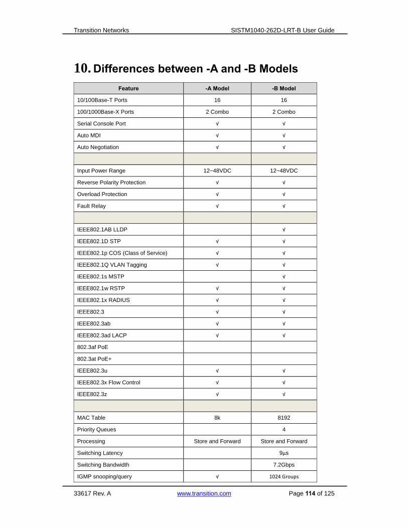
Transition Networks SISTM1040-262D-LRT-B User Guide
33617 Rev. A www.transition.com Page 114 of 125
10. Differences between -A and -B Models
Feature -A Model -B Model
10/100Base-T Ports 16 16
100/1000Base-X Ports 2 Combo 2 Combo
Serial Console Port √ √
Auto MDI √ √
Auto Negotiation √ √
Input Power Range 12~48VDC 12~48VDC
Reverse Polarity Protection √ √
Overload Protection √ √
Fault Relay √ √
IEEE802.1AB LLDP √
IEEE802.1D STP √ √
IEEE802.1p COS (Class of Service) √ √
IEEE802.1Q VLAN Tagging √ √
IEEE802.1s MSTP √
IEEE802.1w RSTP √ √
IEEE802.1x RADIUS √ √
IEEE802.3 √ √
IEEE802.3ab √ √
IEEE802.3ad LACP √ √
802.3af PoE
802.3at PoE+
IEEE802.3u √ √
IEEE802.3x Flow Control √ √
IEEE802.3z √ √
MAC Table 8k 8192
Priority Queues 4
Processing Store and Forward Store and Forward
Switching Latency 9µs
Switching Bandwidth 7.2Gbps
IGMP snooping/query √ 1024 Groups

Transition Networks SISTM1040-262D-LRT-B User Guide
33617 Rev. A www.transition.com Page 115 of 125
SNMPv1/v2/v3 √ √
SNTP √ √
DHCP √ √
PTP √
MVR √
SMTP √
GVRP √ √
VLAN √ 4096
Modbus TCP √
O-Ring √
Open-Ring √
Multi-ring √
X-Ring √
Dual Homing √ √
Dual Ring √ √
Couple Ring √ √
MRP √
IP Access Security √ √
Port and IP Binding √ √
SSL √
SYSLOG √ √
IPv4/IPv6 √ √
Power LEDS Power, P1, P2 Power, P1, P2
Ring Master LED 1 1
Ring Indicator 1
Fault Indicator 1 1
10/100/1000Base-T Link/Act/100Mbps 1/Port 1/Port
100/1000Base-X Link/Act 1/Port 1/Port
Enclosure IP-30 IP-30
Dimensions 79 X 105 X 152 96.4 X 108.5 X 154
Operating Temperature -40⁰C to +75⁰C -40⁰C to +70⁰C
MTBF 295000 Hrs

Transition Networks SISTM1040-262D-LRT-B User Guide
33617 Rev. A www.transition.com Page 116 of 125
Feature -A Model -B Model
FCC Part 15 √ √
CISPR(EN55022) class A √ √
EN61000-4-2 (ESD) √ √
EN61000-4-3 (RS) √ √
EN61000-4-4 (EFT) √ √
EN61000-4-5 (Surge) √ √
EN61000-4-6 (CS) √ √
EN61000-4-8 √ √
EN61000-4-11 √
IEC60068-2-27 (Shock) √ √
IEC60068-2-32 (Free Fall) √ √
IEC60068-2-6 (Vibration) √ √
IEC61000-6-2
IEC61000-6-4
UL √ √
UL508
cUL √ √
Class 1/Div 2 √
CE Mark √ √
ATEX √
GL

Transition Networks SISTM1040-262D-LRT-B User Guide
33617 Rev. A www.transition.com Page 117 of 125
11. Power Supply Information
Several power supply models are available from Transition Networks.
Warning: You must use an isolated power supply in order for Transition Networks to honor
the warranty.
Transition Networks recommended power supply:
25083: 24 Watt 12VDC DIN-Rail power supply.
Alternate Power Supply:
25130: 40 Watt 48VDC DIN-Rail power supply.

Transition Networks SISTM1040-262D-LRT-B User Guide
33617 Rev. A www.transition.com Page 118 of 125
12. Radius Server and Switch Settings This section provides MS WinRadius and Windows / PC settings. See section 5.1.12.4 -
“802.1x - Radius Server” for the switch’s RADIUS parameter descriptions.
Radius Server and Switch Setting
1. Enable the WinRadius tool.
2. Set the Radius Server IP、NSA and Port.
3. Create a new User.
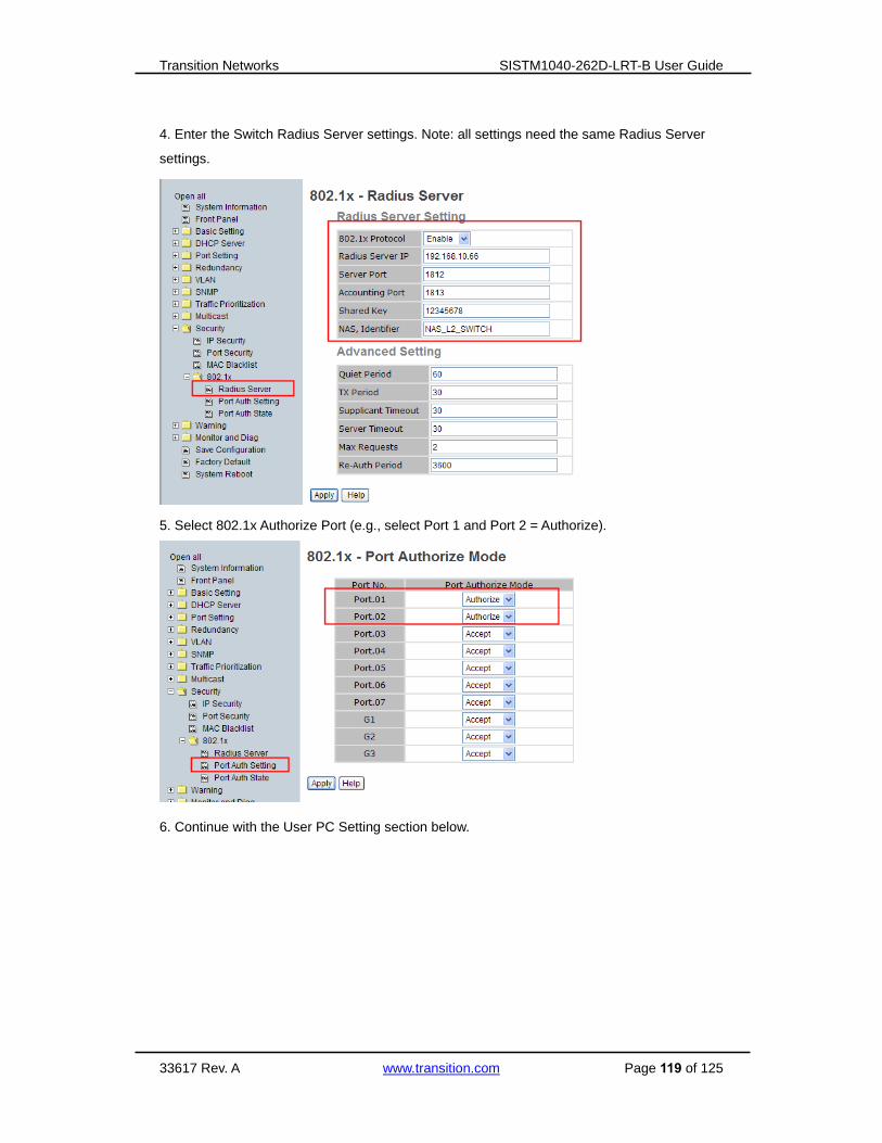
Transition Networks SISTM1040-262D-LRT-B User Guide
33617 Rev. A www.transition.com Page 119 of 125
4. Enter the Switch Radius Server settings. Note: all settings need the same Radius Server
settings.
5. Select 802.1x Authorize Port (e.g., select Port 1 and Port 2 = Authorize).
6. Continue with the User PC Setting section below.

Transition Networks SISTM1040-262D-LRT-B User Guide
33617 Rev. A www.transition.com Page 120 of 125
User PC Settings
1. Enable Windows 802.1x Services: To complete this procedure, you must first enable
the Wired AutoConfig service, which is turned off by default.
a. Click the Start button . In the search box, type services.msc, and then
press Enter. If you are prompted for an administrator password or
confirmation, type the password or provide confirmation.
b. In the Services dialog box, click the Standard tab at the bottom of main pane,
right-click Wired AutoConfig, and then click Start.
c. Open Network Connections by clicking the Start button , and then clicking
Control Panel. In the search box, type adapter, and then, under Network and
Sharing Center, click View network connections.
d. Right-click the connection that you want to enable 802.1X authentication for,
and then click Properties. If you are prompted for an administrator
password or confirmation, type the password or provide confirmation.

Transition Networks SISTM1040-262D-LRT-B User Guide
33617 Rev. A www.transition.com Page 121 of 125
a. Click the Authentication tab, and then select the Enable IEEE 802.1X
authentication check box.
b. In the Choose a network authentication method list, click the method you want to
use.
To configure additional settings, click Settings.

Transition Networks SISTM1040-262D-LRT-B User Guide
33617 Rev. A www.transition.com Page 122 of 125
13. SNTP Server Setup
This section provides a sample setup procedure for the following SNTP server/client
configuration.
1. Set up IP of PC (e.g., 192.168.1.66 / 24).
2. Start the SNTP Server software, making the PC into an SNTPand Syslog Server (this
example uses the free tool tftpd32).

Transition Networks SISTM1040-262D-LRT-B User Guide
33617 Rev. A www.transition.com Page 123 of 125
3. Confirm whether to open the SNTP function.
4. Set up and finish, then restart the software.
5. At the Basic Setting > SNTP(Time) page, set the SNTP Server IP Address and the set
the UTC Timezone, and click the Apply button.
6. Observe the system time at the System Information page in the System Timezone Offset
field.

Transition Networks SISTM1040-262D-LRT-B User Guide
33617 Rev. A www.transition.com Page 124 of 125
Transition Networks
10900 Red Circle Drive
Minnetonka, MN 55343 USA
Tel: 952- 941-7600 or 1-800-526-9267
Fax: 952-941-2322
Copyright © 2015 Transition Networks. All rights reserved.
Printed in the U.S.A.
SISTM1040-262D-LRT-B Hardened Managed Ethernet Switch User Guide, 33617 Rev. A

![[A4] GOALOU Bertrand_Astana LRT](https://static.fdocuments.net/doc/165x107/54521cd7b1af9f72248b4d80/a4-goalou-bertrandastana-lrt.jpg)