
SISTEMI EMBEDDED AA 2012/2013
23
SISTEMI EMBEDDED AA 2012/2013 SOPC Nios II Interval Timer Core
Transcript of SISTEMI EMBEDDED AA 2012/2013
SISTEMI EMBEDDEDAA 2012/2013
SOPC Nios II
Interval Timer Core
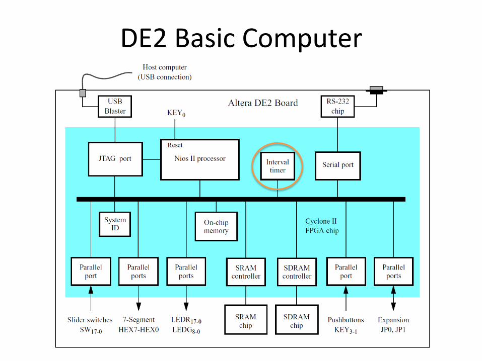
DE2 Basic Computer
Interval timer core (1)
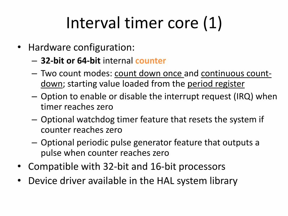
• Hardware configuration:– 32-bit or 64-bit internal counter
– Two count modes: count down once and continuous count-down; starting value loaded from the period register
– Option to enable or disable the interrupt request (IRQ) when timer reaches zero
– Optional watchdog timer feature that resets the system if counter reaches zero
– Optional periodic pulse generator feature that outputs a pulse when counter reaches zero
• Compatible with 32-bit and 16-bit processors
• Device driver available in the HAL system library

Interval timer core (2)
• Block diagram
– 6x (32-bit counter) or 10x (64-bit counter) 16-bit registers (certain registers may not be present depending on the core configuration)

Interval timer core (3)• Nios II processor writes the core's control register to:
– Start and stop the counter– Enable/disable the IRQ – Specify count-down once or continuous count-down mode
• A processor reads the status register to gather current timer activity • A processor can specify the timer period by writing
a value to the period registers – An internal counter counts down to zero, and whenever it reaches zero,
it is immediately reloaded from the period registers
• A processor can read the current counter value by first writing to one of the snap registers to request a coherent snapshot of the counter, and then reading the snap registers for the full value
• When the count reaches zero, one or more of the following events are triggered: – If IRQs are enabled, an IRQ is generated – The optional pulse-generator output is asserted for one clock period – The optional watchdog output resets the system
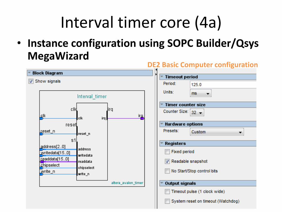
Interval timer core (4a)• Instance configuration using SOPC Builder/Qsys
MegaWizardDE2 Basic Computer configuration
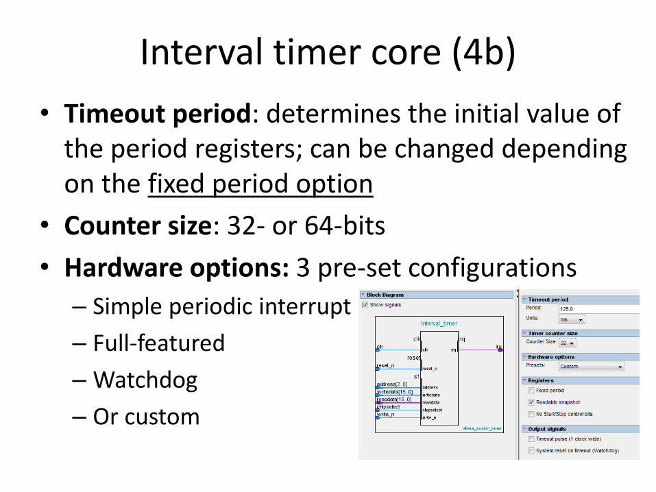
Interval timer core (4b)
• Timeout period: determines the initial value of the period registers; can be changed depending on the fixed period option
• Counter size: 32- or 64-bits
• Hardware options: 3 pre-set configurations
– Simple periodic interrupt
– Full-featured
– Watchdog
– Or custom
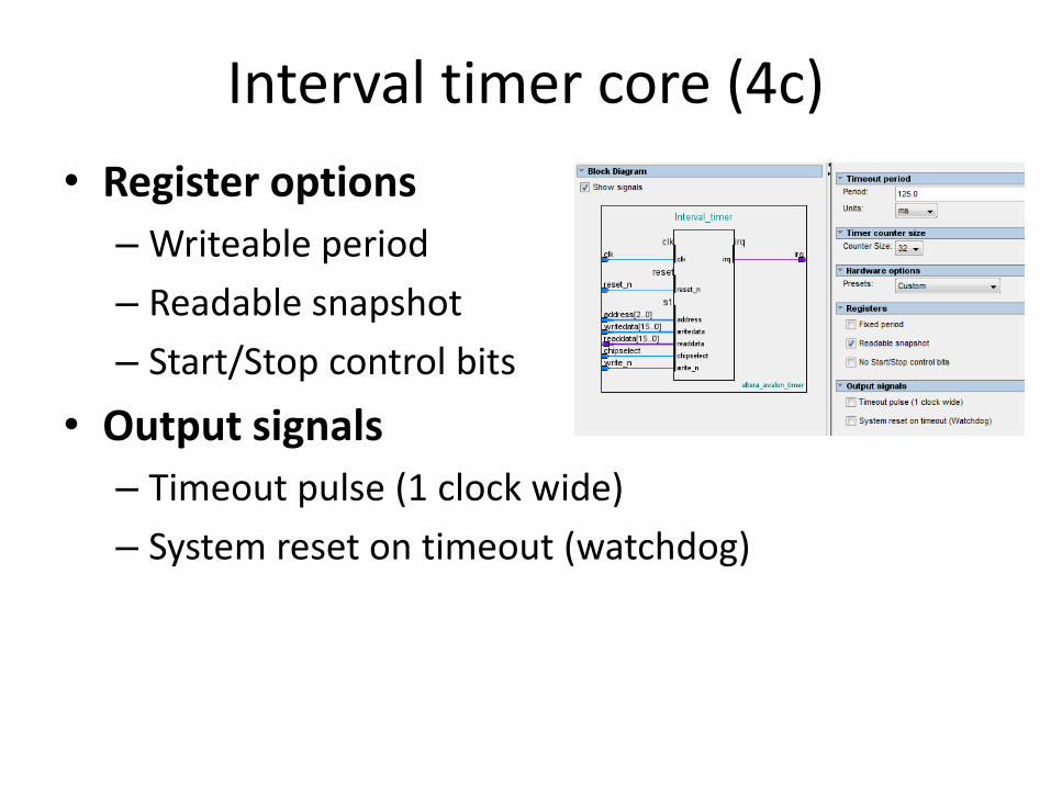
Interval timer core (4c)
• Register options
– Writeable period
– Readable snapshot
– Start/Stop control bits
• Output signals
– Timeout pulse (1 clock wide)
– System reset on timeout (watchdog)

Interval timer core (4d)
• Watchdog configuration:
– Set the Timeout Period to the desired "watchdog" period
– Turn off Writeable period
– Turn off Readable snapshot
– Turn off Start/Stop control bits
– Turn off Timeout pulse
– Turn on System reset on timeout (watchdog)

Interval timer core (4d)• Watchdog behaviour:
– After reset, counter is stopped – It must be started by writing a 1 to the control register's
START bit. Once started, the timer can never be stopped – If the internal counter reaches zero, the watchdog timer
resets the system by generating a pulse on its reset request output
– To prevent the system from resetting, the processor/program must periodically reset the counter's count-down value by writing one of the period registers (the written value is ignored)
– If the processor fails to access the timer because, for example, software has stopped executing normally, the watchdog timer resets the system and returns the system to a defined state

Interval timer core (5a)
• Register map (32-bit internal counter)
• Offset must be multiplied by 4 (32-bit Avalon data bus) and added to the Interval timer BASE ADDRESS to obtain the register address

Interval timer core (5b)
• Status register

Interval timer core (5c)
• Control register

Interval timer core (5d)
• period_n Registers – The period_n registers store the timeout period value – The internal counter is loaded with the value stored in
these registers whenever one of the following occurs: • A write operation to one of the period_n register • The internal counter reaches 0
– Writing to one of the period_n registers stops the internal counter, except when the hardware is configured with Start/Stop control bits off
– When the hardware is configured with Writeable period disabled, writing to one of the period_n registers causes the counter to reset to the fixed Timeout Period specified at system generation time
– The timer's actual period is one cycle greater than the value stored in the period_n registers

Interval timer core (5d)
• snap_n registers
– A master peripheral may request a coherent snapshot of the current internal counter by performing a write operation (write-data ignored) to one of the snap_n registers
– When a write occurs, the value of the counter is copied to the snap_n registers

Interval timer core (6)
• Interrupt Behaviour
– The interval timer core generates an IRQ whenever the internal counter reaches zero and the ITO bit of the control register is set to 1
– Acknowledging the IRQ in one of two ways:
• Clear the TO bit of the status register
• Disable interrupts by clearing the ITO bit of the control register
– Failing to acknowledge the IRQ produces an undefined result

Software programming model (1)
STATUS
Interval timer core
system.h
DeviceDriver
HAL(Custom Device)
altera_up_avalon_timer_regs.h
sys/alt_alarm.h
altera_avalon_timer_sc.c
048
12
altera_up_avalon_timer.h
sys/alt_timestamp.h
altera_avalon_timer_tc.c
Address - base 31 15 0
CONTROLPERIOD_LPERIOD_H
SNAP_L
SNAP_H
1620

Software programming model (2a)
• The device model of the interval timer can be chosen through the BSP editor
• This property is recorded in system.h
/*
* hal configuration
*
*/
#define ALT_MAX_FD 32
#define ALT_SYS_CLK INTERVAL_TIMER
#define ALT_TIMESTAMP_CLK none

Software programming model (2b)• HAL/sys_clk_timer mapped to Interval_timer
• HAL/timestamp_timer mapped to Interval_timer

System clock HAL• Useful for scheduling periodic tasks
– Can generate the system tick – The period of the system tick is a multiple of the Timeout
period of the interval timer
• Basic HAL functions: – int alt_alarm_start( alt_alarm* alarm, alt_u32 nticks,
alt_u32 (*callback) (void* context), void* context ); – void alt_alarm_stop(alt_alarm* alarm); – alt_u32 alt_ticks_per_second(void); – alt_u32 alt_nticks(void); – See the HAL API Reference for how to use these
functions!

Timestamp HAL
• Useful for measuring interval times with high resolution (period of the interval timer clock!)
– The interval timer peripheral must have the period_nregister which is set to the maximum value by the relevant HAL
• Basic HAL functions:
– int alt_timestamp_start(void);
– alt_u32 alt_timestamp(void);
– alt_u32 alt_timestamp_freq(void);
– See the HAL API Reference for how to use these functions!
Putting into practice
• Use the Timestamp HAL to:
– check the delay generated by the Wait_ms() function: displays the result on stdio mapped to JTAG_UART
– measure reaction times
• int printf(const char* format,…)
– Format examples:
• %d integer decimal
• %u unsigned decimal
• %x unsigned hex
• %f double
• …

References
• Altera, “Embedded Peripherals IP User Guide,” ug_embedded_ip.pdf
– 28. Interval Timer
• Altera “Nios II Software Developer’s Handbook,” n2sw_nii5v2.pdf
– Chapters 6. Developing Programs Using Hardware Abstraction Layer