SIRIUS - AiSrl...SIRIUS industrial controls The SIRIUS range has everything you need for switching,...
488
s Answers for industry. SIRIUS Datasheet 2012
Transcript of SIRIUS - AiSrl...SIRIUS industrial controls The SIRIUS range has everything you need for switching,...
s
Answers for industry.
SIRIUSDatasheet 2012
Introduction
Contactors and Contactor Assemblies
SIRIUS 3RW Soft Starter
Protection Equipment
Load Feeders and Motor Starters for Use in the Control Cabinet
Monitoring and Control Devices
2
Introduction
1/2 Answers for Industry.
1/4 Energy efficiency – Benefits for the environment and for your competitiveness.
1/6 Industrial controls. The basis for advanced solutions.
1
1/2
1
Answers for industry.
Siemens Industry answers the challenges in the manufacturing
and the process industry as well as in the building automation
business. Our drive and automation solutions based on Totally
Integrated Automation (TIA) and Totally Integrated Power (TIP)
are employed in all kinds of industry. In the manufacturing
and the process industry. In industrial as well as in functional
buildings.
Siemens offers automation, drive, and low-voltage switching technology as well as industrial software from standard products up to entire industry solutions. The industry software enables our industry customers to optimize the entire value chain – from product design and development through manufacture and sales up to after-sales service. Our electrical and mechanical components offer integrated technologies for the entire drive train – from couplings to gear units, from motors to control and drive solutions for all engineering industries. Our technology platform TIP offers robust solutions for power distribution.
The high quality of our products sets industry-wide benchmarks. High environmental aims are part of our eco-management, and we implement these aims consistently. Right from product design, possible effects on the environment are examined. Hence many of our products and systems are RoHS compliant (Restriction of Hazardous Substances). As a matter of course, our production sites are certified according to DIN EN ISO 14001, but to us, environmental protection also means most efficient utilization of valuable resources. The best example are our energy-efficient drives with energy savings up to 60 %.
Check out the opportunities our automation and drive solutions provide. And discover how you can sustainably enhance your competitive edge with us.
1/3
1

Energy efficiency - benefits for the environment and for your competitiveness.
With its energy-efficient solutions and green technologies, the Siemens
environmental portfolio offers a threefold benefit: for our customers,
improving their bottom line through lower energy costs and higher
productivity; for future generations, helping to maintain and improve
the environment and living conditions; and for Siemens itself, tapping
into attractive markets and securing the company's future.
A wide range of environmental technologies and energy-efficient solutions
Siemens has been supplying products and solutions for environmental protection and climate control since its earliest beginnings. To name but one example, it was back in 1873 that Werner von Siemens developed a technology for avoiding ash emissions from chimneys.
Today, we have the Siemens environmental portfolio in which we bundle those technologies which have been shown to help our customers with pollution control. These include the following:
Products and systems which are far more energy-efficient than comparable solutions, such as gas and steam turbines for solar power, low-energy light bulbs, and intelligent building services engineering
Systems which use renewable sources of energy and their components, such as wind power plants and steam turbines for solar power
Environmental technologies which we harness for the provision of clean water and purer air
The Siemens environmental portfolio covers the entire energy conversion chain – from efficient power generation and energy distribution right through to usage – and green technologies.
SIRIUS industrial controls
The industrial control components are fine-tuned to minimize power loss and thus provide both passive and active support in implementing efficient systems and applications.
The components of SIRIUS Innovations perform at extremely low levels of inherent loss. The new generation heralded a further significant reduction of 10 % on average. This means that not only is it possible to save on energy costs but also to reduce the amount of waste heat in the control cabinet. This then translates to a higher packing density in the control cabinet and a reduction in the required cooling efficiency.
1/4
1
SIRIUS reduces power loss
Our most energy-efficient contactors are fitted with an electronic coil control. This reduces the power loss by up to 92 %.
Our soft starters use intelligent, integrated current bypass circuits. The power loss is thereby reduced by 92 % during operation.
Overload relays are fitted with an electronic release instead of a bimetal trip unit and boast not only a wider setting range but also a reduction of up to 98 % in no-load loss.
In comparison with conventional feeders, the power loss in the compact feeder has been reduced by up to 80 %. This is due to the combination of the most efficient technologies in one unit.
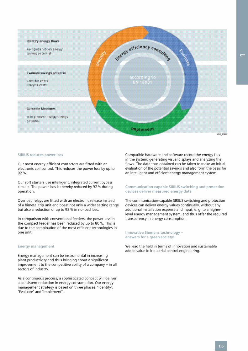
Energy management
Energy management can be instrumental in increasing plant productivity and thus bringing about a significant improvement to the competitive ability of a company – in all sectors of industry.
As a continuous process, a sophisticated concept will deliver a consistent reduction in energy consumption. Our energy management strategy is based on three phases: “Identify”, “Evaluate” and “Implement”.
Compatible hardware and software record the energy flux in the system, generating visual displays and analyzing the flows. The data thus obtained can be taken to make an initial evaluation of the potential savings and also form the basis for an intelligent and efficient energy management system.
Communication-capable SIRIUS switching and protection devices deliver measured energy data
The communication-capable SIRIUS switching and protection devices can deliver energy values continually, without any additional installation expense and input, e. g. to a higher-level energy management system, and thus offer the required transparency in energy consumption.
Innovative Siemens technology – answers for a green society!
We lead the field in terms of innovation and sustainable added value in industrial control engineering.
1/5
1
SIRIUS industrial controls
The SIRIUS range has everything you need for switching, protecting and starting loads. Products for monitoring, control, detection, commanding, signaling and power supply round off the spectrum of industrial controls.
Building control cabinets should be quick, easy, flexible and space-saving. But how can all these requirements be met simultaneously? The answer lies in the unique SIRIUS modular system up to 250 kW / 400 V, where you will find everything that you need for switching, protecting and starting motors and industrial systems.
Furthermore, all components of the SIRIUS modular system are characterized by a space-saving design and high flexibility and are optimally coordinated with each other. Configuring, installing, wiring and maintenance are extremely easy and time-saving to perform.
Regardless of whether you want to build up your own load feeders with motor starter protectors/circuit breakers or overload relays, contactors or soft starters, or decide instead in favor of preassembled feeders: SIRIUS has the right product for every application.
Continuous further development and regular innovations ensure that our customers are optimally equipped with SIRIUS and benefit from efficient solutions − today and tomorrow.
Systematic further development – SIRIUS Innovations
SIRIUS has long been synonymous world-wide with industrial controls and has been a trendsetter in this field from the very beginning. The SIRIUS modular system with its components for the switching, starting, protection and monitoring of motors and industrial systems stands for the fast, flexible and space-saving construction of control cabinets.
With its latest innovations for the main and control circuit, the new SIRIUS modular system has underlined its leading position once again.
The consistent further development of SIRIUS takes even better account of current market requirements, particularly the call for fewer variants, greater flexibility and reduced cost and time. The advantages for you are: higher productivity and cost efficiency in your company.
Clicking replaces wiring
In the portfolio of the SIRIUS modular system you can trust on finding perfectly coordinated and flexibly combinable components which now are even easier to install: plug in place, connect, click and that’s it! Complicated wiring is a thing of the past, as are wiring errors. For you this means a significant reduction of time and cost.
Innovative through and through
The SIRIUS modular system in sizes S00 and S0 up to 40 A has been completely revised − with respect to the main and control circuit. As the result, the innovative basic components such as motor starter protectors and contactors provide a host of advantages to optimize your plant, today and in the future. Often the innovation is to be found in the details. For example, more power in the same design and the bundling of functions in basic devices for notable space savings.
At the same time the innovations enable the greatest flexibility. Be it direct starting, reverse starting or wye-delta starting for customer assembly, as a tested combination or an “all-in-one” solution complete with the compact starter, for soft starting or for frequent switching: the SIRIUS modular system offers the perfect answer.
Industrial controls. The basis for innovative solutions.
High demands are made in the field of industrial controls:
Users want cost-effective solutions which can be easily integrated in
control cabinets, distribution boards and distributed systems and which
can communicate perfectly with each other.
Our response to their demands are SIRIUS industrial controls.
1/6
1
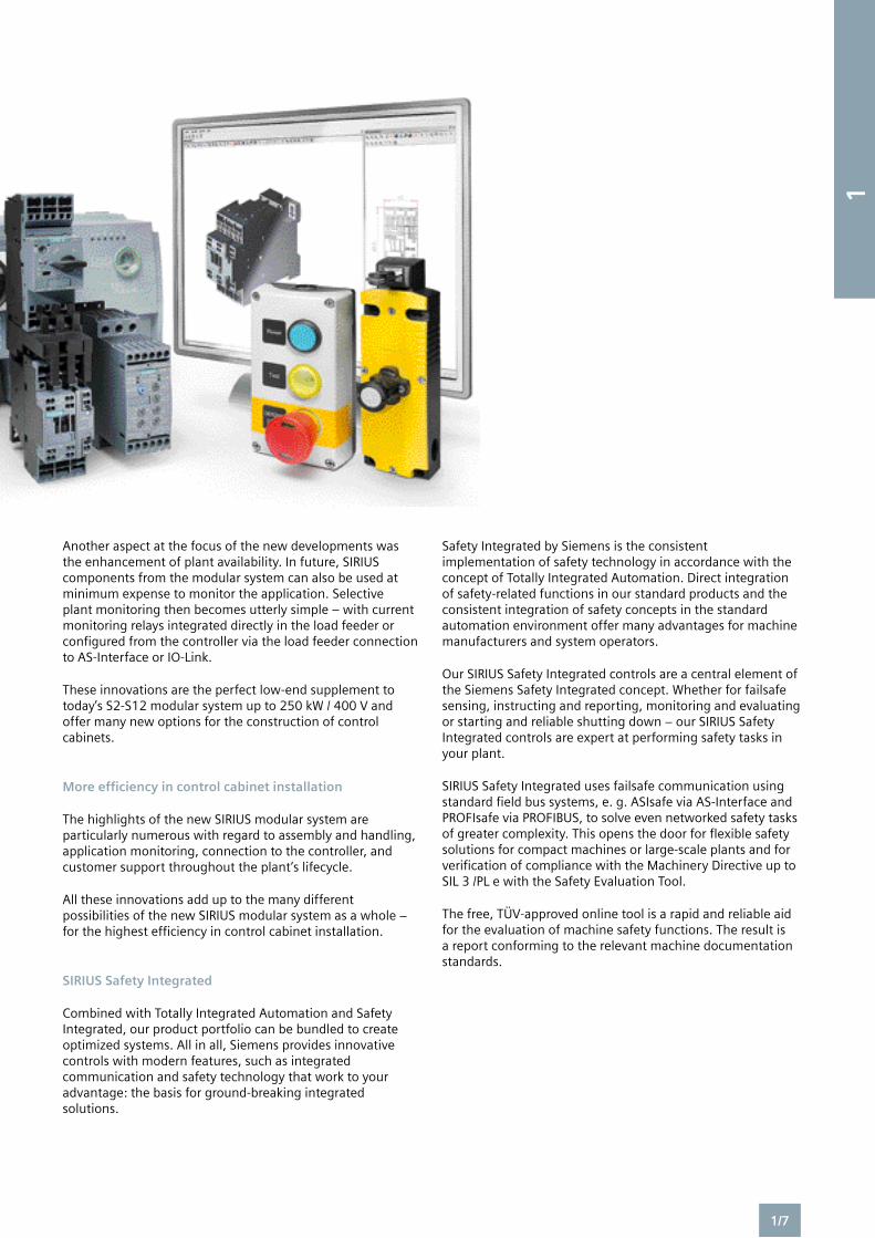
Another aspect at the focus of the new developments was the enhancement of plant availability. In future, SIRIUS components from the modular system can also be used at minimum expense to monitor the application. Selective plant monitoring then becomes utterly simple – with current monitoring relays integrated directly in the load feeder or configured from the controller via the load feeder connection to AS-Interface or IO-Link.
These innovations are the perfect low-end supplement to today’s S2-S12 modular system up to 250 kW / 400 V and offer many new options for the construction of control cabinets.
More efficiency in control cabinet installation
The highlights of the new SIRIUS modular system are particularly numerous with regard to assembly and handling, application monitoring, connection to the controller, and customer support throughout the plant’s lifecycle.
All these innovations add up to the many different possibilities of the new SIRIUS modular system as a whole − for the highest efficiency in control cabinet installation.
SIRIUS Safety Integrated
Combined with Totally Integrated Automation and Safety Integrated, our product portfolio can be bundled to create optimized systems. All in all, Siemens provides innovative controls with modern features, such as integrated communication and safety technology that work to your advantage: the basis for ground-breaking integrated solutions.
Safety Integrated by Siemens is the consistent implementation of safety technology in accordance with the concept of Totally Integrated Automation. Direct integration of safety-related functions in our standard products and the consistent integration of safety concepts in the standard automation environment offer many advantages for machine manufacturers and system operators.
Our SIRIUS Safety Integrated controls are a central element of the Siemens Safety Integrated concept. Whether for failsafe sensing, instructing and reporting, monitoring and evaluating or starting and reliable shutting down − our SIRIUS Safety Integrated controls are expert at performing safety tasks in your plant.
SIRIUS Safety Integrated uses failsafe communication using standard field bus systems, e. g. ASIsafe via AS-Interface and PROFIsafe via PROFIBUS, to solve even networked safety tasks of greater complexity. This opens the door for flexible safety solutions for compact machines or large-scale plants and for verification of compliance with the Machinery Directive up to SIL 3 /PL e with the Safety Evaluation Tool.
The free, TÜV-approved online tool is a rapid and reliable aid for the evaluation of machine safety functions. The result is a report conforming to the relevant machine documentation standards.
1/7
1

Notes
1/8
1
2Contactors for Switching DC voltage
2/117 3TC contactors, 1- and 2-pole, 32 ... 400 A
Contactor Relays
2/121 SIRIUS 3RH2 contactor relays, 4-pole new
2/130 SIRIUS 3RH24 latched contactor relays, 4-pole new
2/131 SIRIUS 3RH21 coupling relays for switching auxiliary circuits, 4-pole new
Coupling Contactors
2/133 SIRIUS 3RT20 coupling contactors (interface), 3-pole, 3 ... 15 kW new
Function Modules for Mounting onto SIRIUS 3RT2 Contactors new
2/137 Introduction
2/138 SIRIUS function modules
2/142 SIRIUS function modules for IO-Link
2/147 SIRIUS function modules for AS-Interface
Accessories and Spare Parts
For 3RT2, 3RH2 Contactors and Contactor Relays new
2/151 Accessories for 3RT2, 3RH2 contactors and contactor relays
2/168 Spare parts for 3RT2 contactors
For 3RT1, 3RH1 Contactors and Contactor Relays
2/169 Accessories for 3RT1, 3RH1 contactors and contactor relays
2/186 Spare parts for 3RT1 contactors
For 3T Contactors and Contactor Relays
2/188 Accessories for 3TC, 3TF6 contactors
2/191 Spare parts for 3TC, 3TF, 3TK contactors
Controls – Contactors and Contactor Assemblies
2/2 Introduction
Power Contactors for Switching Motors
2/5 General data
2/11 SIRIUS 3RT20 contactors, 3-pole, 3 ... 18.5 kW new
2/30 SIRIUS 3RT10 contactors, 3-pole, 15 ... 250 kW
2/50 SIRIUS 3RT12 vacuum contactors, 3-pole, 110 ... 250 kW
2/55 3TF6 vacuum contactors, 3-pole, 335 ... 450 kW
Contactor Assemblies
3RA23, 3RA13, 3RA24, 3RA14 Contactor Assemblies
2/61 SIRIUS 3RA23 reversing contactor assemblies new
2/69 SIRIUS 3RA13 reversing contactor assemblies
2/75 SIRIUS 3RA24 contactor assemblies for wye-delta starting new
2/84 SIRIUS 3RA14 contactor assemblies for wye-delta starting
Contactors for Special Applications
2/91 SIRIUS 3RT14 contactors for resistive loads (AC-1), 3-pole, 140 ... 690 A
2/98 SIRIUS 3RT23 contactors for resistive loads (AC-1), 4-pole, 4 NO, 18 ... 50 A new
2/102 SIRIUS 3RT13 contactors for resistive loads (AC-1), 4-pole, 4 NO, 60 ... 140 A
2/105 3TK1 contactors for resistive loads (AC-1), 4-pole, 4 NO, 200 ... 1000 A
2/108 SIRIUS 3RT25 contactors, 4-pole, 2 NO + 2 NC, 4 ... 11 kW
2/112 SIRIUS 3RT15 contactors, 4-pole, 2 NO + 2 NC, 18.5 kW
2/114 SIRIUS 3RT16 capacitor contactors, 12.5 ... 50 kvar
2
Overview
SizeType
S00 3RT20 1
S0 3RT20 2
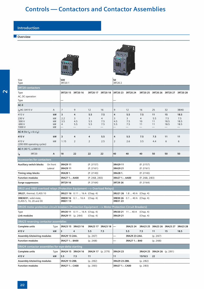
3RT20 contactors
Type
AC, DC operation
Type
3RT20 15
—
3RT20 16 3RT20 17 3RT20 18 3RT20 23
—
3RT20 24 3RT20 25 3RT20 26 3RT20 27 3RT20 28
AC-3
Ie/AC-3/415 V A 7 9 12 16 9 12 16 25 32 38/40
415 V
230 V 500 V 690 V 1000 V
kW
kW kW kW kW
3
2.2 3.5 4 —
4
3 4.5 5.5 —
5.5
3 5.5 5.5 —
7.5
4 7.5 7.5 —
4
3 4.5 5.5 —
5.5
3 7.5 7.5 —
7.5
4 10 11 —
11
5.5 11 11 —
15
7.5 18.5 18.5 —
18.5
7.5 18.5 18.5 —
AC-4 (for Ia = 6 x Ie)
415 V kW 3 4 4 5.5 4 5.5 7.5 7.5 11 11
415 V (200 000 operating cycles)
kW 1.15 2 2 2.5 2 2.6 3.5 4.4 6 6
AC-1 (40 °C, ≤ 690 V)
Ie 3RT20 A 18 22 22 22 40 40 40 50 50 50
Accessories for contactors
Auxiliary switch blocks On front
Lateral
3RH29 11
3RH29 11
(P. 2/157)
(P. 2/161)
3RH29 11
3RH29 21
(P. 2/157)
(P. 2/161)
Timing relay blocks 3RA28 1. (P. 2/140) 3RA28 1. (P. 2/140)
Function modules 3RA27 1.-. AA00 (P. 2/68, 2/83) 3RA27 1.-. AA00 (P. 2/68, 2/83)
Surge suppressors 3RT29 16 (P. 2/164) 3RT29 26 (P. 2/164)
3RU2 and 3RB3 overload relays (Protection Equipment —> Overload Relays)
3RU21, thermal, CLASS 10 3RU21 16 0.11 ... 16 A (Chap. 4) 3RU21 26 1.8 ... 40 A (Chap. 4)
3RB30/31, solid-state, CLASS 5, 10, 20 and 30
3RB30 16 3RB31 13
0.1 ... 16 A (Chap. 4) 3RB30 26 3RB31 23
0.1 ... 40 A (Chap. 4)
3RV20 motor protection circuit breakers (Protection Equipment —> Motor Protection Circuit Breakers)
Type
Link modules
3RV20 11
3RA29 11
0.11 ... 16 A
(p. 2/64)
(Chap. 4)
(Chap. 4)
3RV20 21
3RA29 21
11 ... 40 A (Chap. 4)
(Chap. 4)
3RA23 reversing contactor assemblies
Complete units Type 3RA23 15 3RA23 16 3RA23 17 3RA23 18 — 3RA23 24 3RA23 25 3RA23 26 3RA23 27 3RA23 28
415 V kW 3 4 5.5 7.5 5.5 7.5 11 15 18.5
Assembly kits/wiring modules 3RA29 13-2AA. (p. 2/67) — 3RA29 23-2AA. (p. 2/67)
Function modules 3RA27 1.-. BA00 (p. 2/68) — 3RA27 1.-. BA0 (p. 2/68)
3RA24 contactor assemblies for wye-delta starting
Complete units Type 3RA24 15 3RA24 16 3RA24 17 (p. 2/79) 3RA24 23 3RA24 25 3RA24 26 (p. 2/81)
415 V kW 5.5 7.5 11 11 15/18.5 22
Assembly kits/wiring modules 3RA29 13-2BB. (p. 2/82) 3RA29 23-2BB. (p. 2/82)
Function modules 3RA27 1.-. CA00 (p. 2/83) 3RA27 1.-. CA00 (p. 2/83)
Controls — Contactors and Contactor Assemblies
Introduction Introduction
2/2
2
Controls — Contactors and Contactor Assemblies
Introduction
SizeType
S23RT10 3
S33RT1. 4
S63RT1. 5
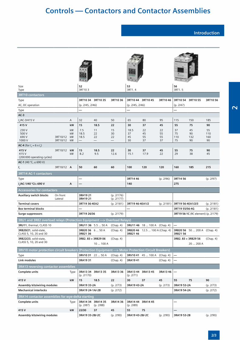
3RT10 contactors
Type 3RT10 34 3RT10 35 3RT10 36 3RT10 44 3RT10 45 3RT10 46 3RT10 54 3RT10 55 3RT10 56
AC, DC operation (p. 2/45, 2/46) (p. 2/45, 2/46) (p. 2/47)
Type — — —
AC-3
Ie/AC-3/415 V A 32 40 50 65 80 95 115 150 185
415 V kW 15 18.5 22 30 37 45 55 75 90
230 V 500 V 690 V 1000 V
3RT10/12 3RT10/12
kW kW kW kW
7.5 18.5 18.5 —
11 22 22 —
15 30 22 —
18.5 37 45 30
22 45 55 37
22 55 55 37
37 75 110 75
45 90 132 90
55 110 160 90
AC-4 (for Ia = 6 x Ie)
415 V 415 V (200 000 operating cycles)
3RT10/12 kW kW
15 8.2
18.5 9.5
22 12.6
30 15.1
37 17.9
45 22
55 29
75 38
90 45
AC-1 (40 °C, ≤ 690 V)
Ie 3RT10/12 A 50 60 60 100 120 120 160 185 215
3RT14 AC-1 contactors
Type — 3RT14 46 (p. 2/96) 3RT14 56 (p. 2/97)
Ie/AC-1/40 °C/≤ 690 V A — 140 275
Accessories for contactors
Auxiliary switch blocks On frontLateral
3RH19 213RH19 21
(p. 2/176)(p. 2/177)
Terminal covers 3RT19 36-4EA2 (p. 2/181) 3RT19 46-4EA1/2 (p. 2/181) 3RT19 56-4EA1/2/3 (p. 2/181)
Box terminal blocks — — 3RT19 55/56-4G (p. 2/181)
Surge suppressors 3RT19 26/36 (p. 2/179) 3RT19 56-1C (RC element) (p. 2/179)
3RU1 and 3RB2 overload relays (Protection Equipment —> Overload Relays)
3RU11, thermal, CLASS 10 3RU11 36 5.5 ... 50 A (Chap. 4) 3RU11 46 18 ... 100 A (Chap. 4) —
3RB20/21, solid-state, CLASS 5, 10, 20 and 30
3RB20 363RB21 36
6 ... 50 A (Chap. 4) 3RB20 463RB21 46
12.5 ... 100 A (Chap. 4) 3RB20 563RB21 56
50 ... 200 A (Chap. 4)
3RB22/23, solid-state, CLASS 5, 10, 20 and 30
3RB2. 83 + 3RB29 06 (Chap. 4) 3RB2. 83 + 3RB29 56 (Chap. 4)
10 ... 100 A 20 ... 200 A
3RV10 motor protection circuit breakers (Protection Equipment —> Motor Protection Circuit Breakers)
Type 3RV10 31 22 ... 50 A (Chap. 4) 3RV10 41 45 ... 100 A (Chap. 4) —
Link modules 3RA19 31 (Chap. 4) 3RA19 41 (Chap. 4) —
3RA13 reversing contactor assemblies
Complete units Type 3RA13 34(p. 2/170)
3RA13 35 3RA13 36 3RA13 44(p. 2/71)
3RA13 45 3RA13 46 —
415 V kW 15 18.5 22 30 37 45 55 75 90
Assembly kits/wiring modules 3RA19 33-2A (p. 2/73) 3RA19 43-2A (p. 2/73) 3RA19 53-2A (p. 2/73)
Mechanical interlocks 3RA19 24-1A/-2B (p. 2/72) 3RA19 54-2A (p. 2/72)
3RA14 contactor assemblies for wye-delta starting
Complete units Type 3RA14 34(p. 2/87)
3RA14 35(p. 2/88)
3RA14 36 3RA14 44(p. 2/89)
3RA14 45 —
415 V kW 22/30 37 45 55 75 —
Assembly kits/wiring modules 3RA19 33-2B/-2C (p. 2/90) 3RA19 43-2B/-2C (p. 2/90) 3RA19 53-2B (p. 2/90)
Introduction
2/3
2
Controls — Contactors and Contactor Assemblies
Introduction
SizeType
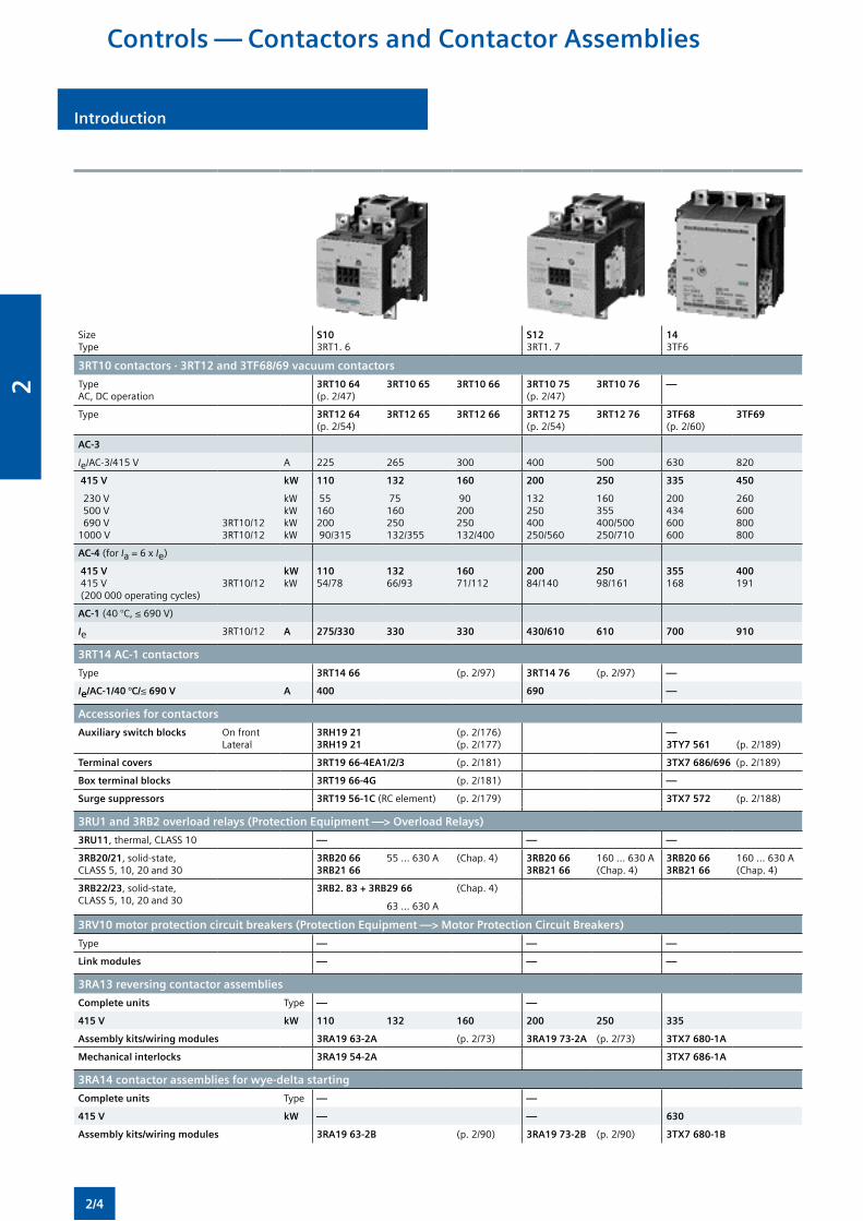
S103RT1. 6
S123RT1. 7
143TF6
3RT10 contactors · 3RT12 and 3TF68/69 vacuum contactors
TypeAC, DC operation
3RT10 64(p. 2/47)
3RT10 65 3RT10 66 3RT10 75(p. 2/47)
3RT10 76 —
Type 3RT12 64(p. 2/54)
3RT12 65 3RT12 66 3RT12 75(p. 2/54)
3RT12 76 3TF68(p. 2/60)
3TF69
AC-3
Ie/AC-3/415 V A 225 265 300 400 500 630 820
415 V kW 110 132 160 200 250 335 450
230 V 500 V 690 V 1000 V
3RT10/12 3RT10/12
kW kW kW kW
55 160 200 90/315
75 160 250 132/355
90 200 250 132/400
132 250 400 250/560
160 355 400/500 250/710
200 434 600 600
260 600 800 800
AC-4 (for Ia = 6 x Ie)
415 V 415 V (200 000 operating cycles)
3RT10/12kWkW
11054/78
13266/93
16071/112
20084/140
25098/161
355168
400191
AC-1 (40 °C, ≤ 690 V)
Ie 3RT10/12 A 275/330 330 330 430/610 610 700 910
3RT14 AC-1 contactors
Type 3RT14 66 (p. 2/97) 3RT14 76 (p. 2/97) —
Ie/AC-1/40 °C/≤ 690 V A 400 690 —
Accessories for contactors
Auxiliary switch blocks On frontLateral
3RH19 213RH19 21
(p. 2/176)(p. 2/177)
—3TY7 561 (p. 2/189)
Terminal covers 3RT19 66-4EA1/2/3 (p. 2/181) 3TX7 686/696 (p. 2/189)
Box terminal blocks 3RT19 66-4G (p. 2/181) —
Surge suppressors 3RT19 56-1C (RC element) (p. 2/179) 3TX7 572 (p. 2/188)
3RU1 and 3RB2 overload relays (Protection Equipment —> Overload Relays)
3RU11, thermal, CLASS 10 — — —
3RB20/21, solid-state, CLASS 5, 10, 20 and 30
3RB20 663RB21 66
55 ... 630 A (Chap. 4) 3RB20 663RB21 66
160 ... 630 A(Chap. 4)
3RB20 663RB21 66
160 ... 630 A(Chap. 4)
3RB22/23, solid-state, CLASS 5, 10, 20 and 30
3RB2. 83 + 3RB29 66 (Chap. 4)
63 ... 630 A
3RV10 motor protection circuit breakers (Protection Equipment —> Motor Protection Circuit Breakers)
Type — — —
Link modules — — —
3RA13 reversing contactor assemblies
Complete units Type — —
415 V kW 110 132 160 200 250 335
Assembly kits/wiring modules 3RA19 63-2A (p. 2/73) 3RA19 73-2A (p. 2/73) 3TX7 680-1A
Mechanical interlocks 3RA19 54-2A 3TX7 686-1A
3RA14 contactor assemblies for wye-delta starting
Complete units Type — —
415 V kW — — 630
Assembly kits/wiring modules 3RA19 63-2B (p. 2/90) 3RA19 73-2B (p. 2/90) 3TX7 680-1B
Introduction
2/4
2
General data
Overview
General data
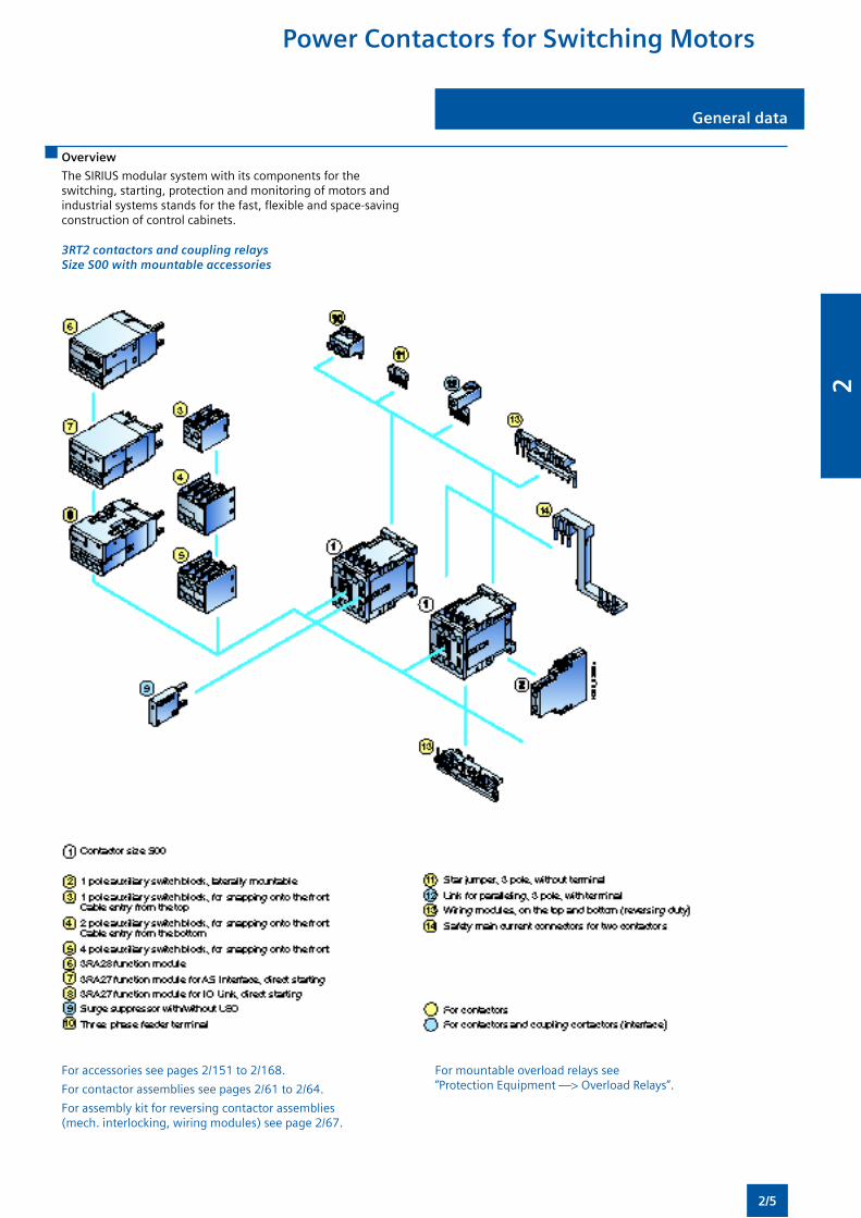
The SIRIUS modular system with its components for the switching, starting, protection and monitoring of motors and industrial systems stands for the fast, flexible and space-saving construction of control cabinets.
3RT2 contactors and coupling relays Size S00 with mountable accessories
For accessories see pages 2/151 to 2/168.
For contactor assemblies see pages 2/61 to 2/64.
For assembly kit for reversing contactor assemblies (mech. interlocking, wiring modules) see page 2/67.
For mountable overload relays see “Protection Equipment —> Overload Relays”.
Power Contactors for Switching Motors
2/5
2
Power Contactors for Switching Motors
General data General data
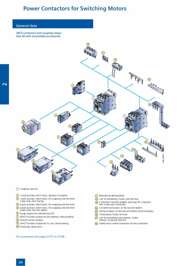
3RT2 contactors and coupling relays Size S0 with mountable accessories
For accessories see pages 2/151 to 2/168.
2/6
2
General dataGeneral data
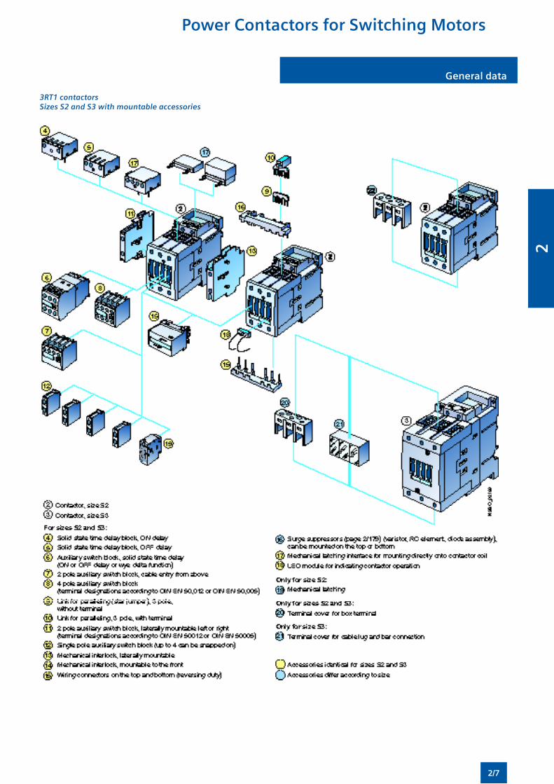
3RT1 contactors Sizes S2 and S3 with mountable accessories
Power Contactors for Switching Motors
2/7
2
Power Contactors for Switching Motors
General data General data
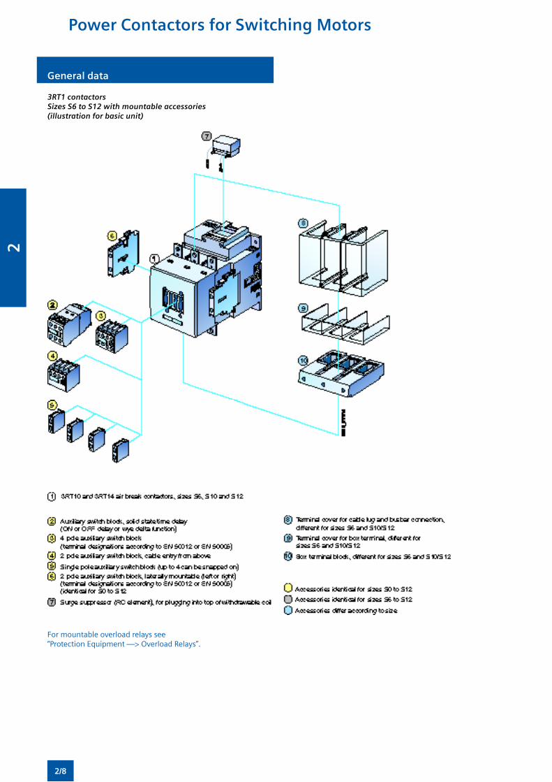
3RT1 contactors Sizes S6 to S12 with mountable accessories (illustration for basic unit)
For mountable overload relays see “Protection Equipment —> Overload Relays”.
2/8
2
General dataGeneral data
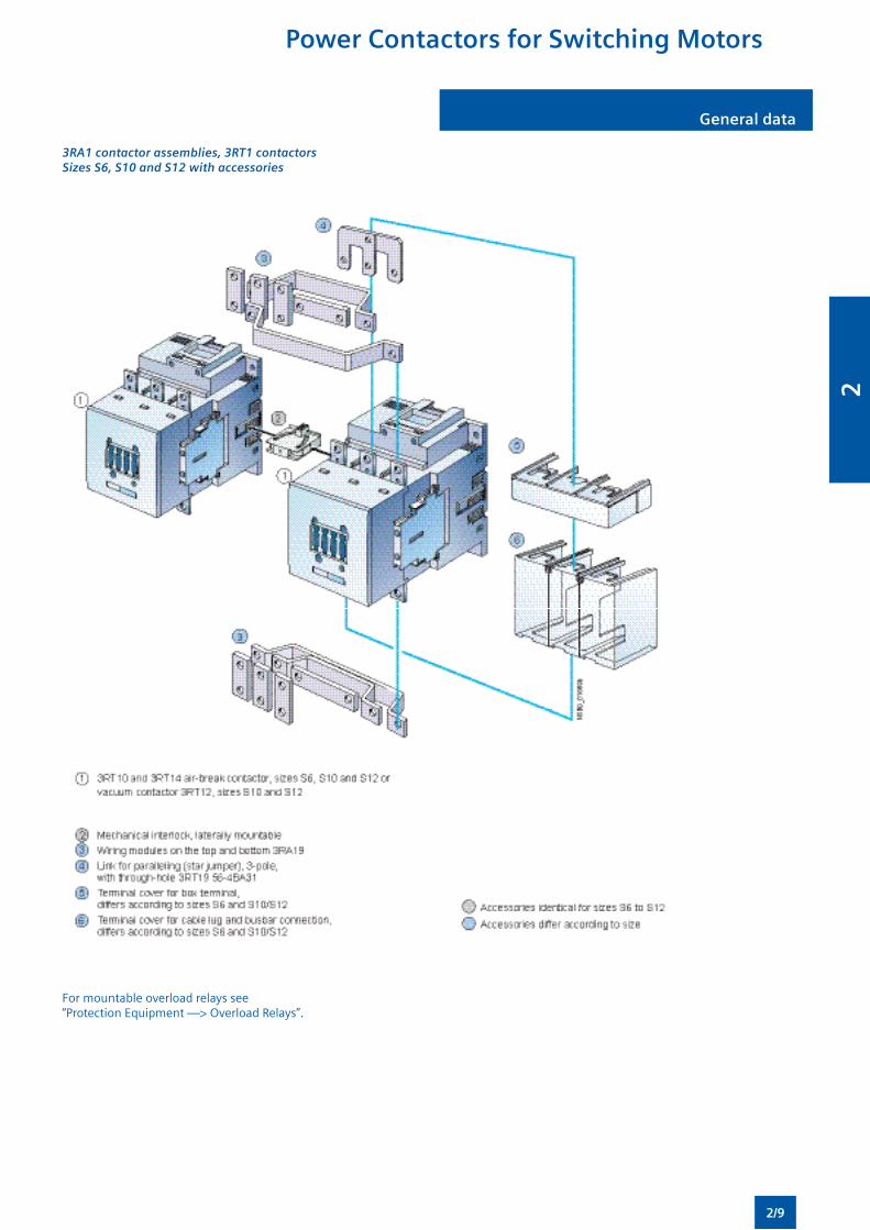
3RA1 contactor assemblies, 3RT1 contactors Sizes S6, S10 and S12 with accessories
For mountable overload relays see “Protection Equipment —> Overload Relays”.
Power Contactors for Switching Motors
2/9
2
Power Contactors for Switching Motors
General data General data
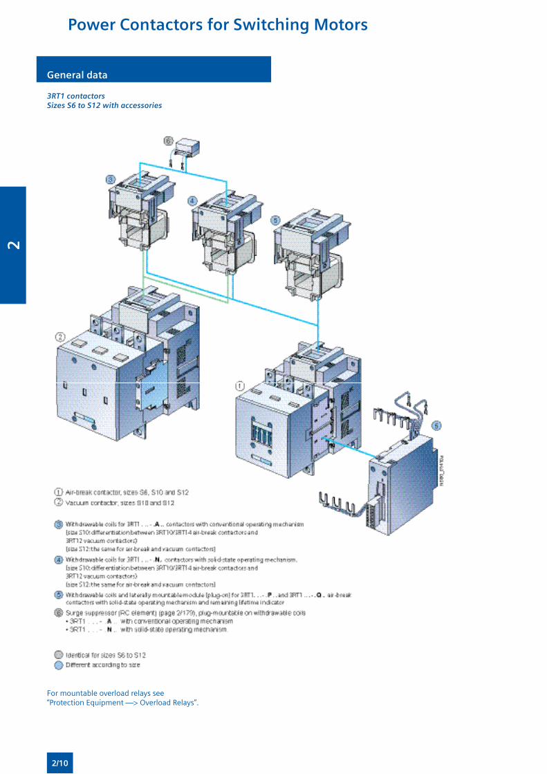
3RT1 contactors Sizes S6 to S12 with accessories
For mountable overload relays see “Protection Equipment —> Overload Relays”.
2/10
2
SIRIUS 3RT20 contactors,3-pole, 3 ... 18.5 kW
SIRIUS 3RT20 contactors,3-pole, 3 ... 18.5 kW
Overview
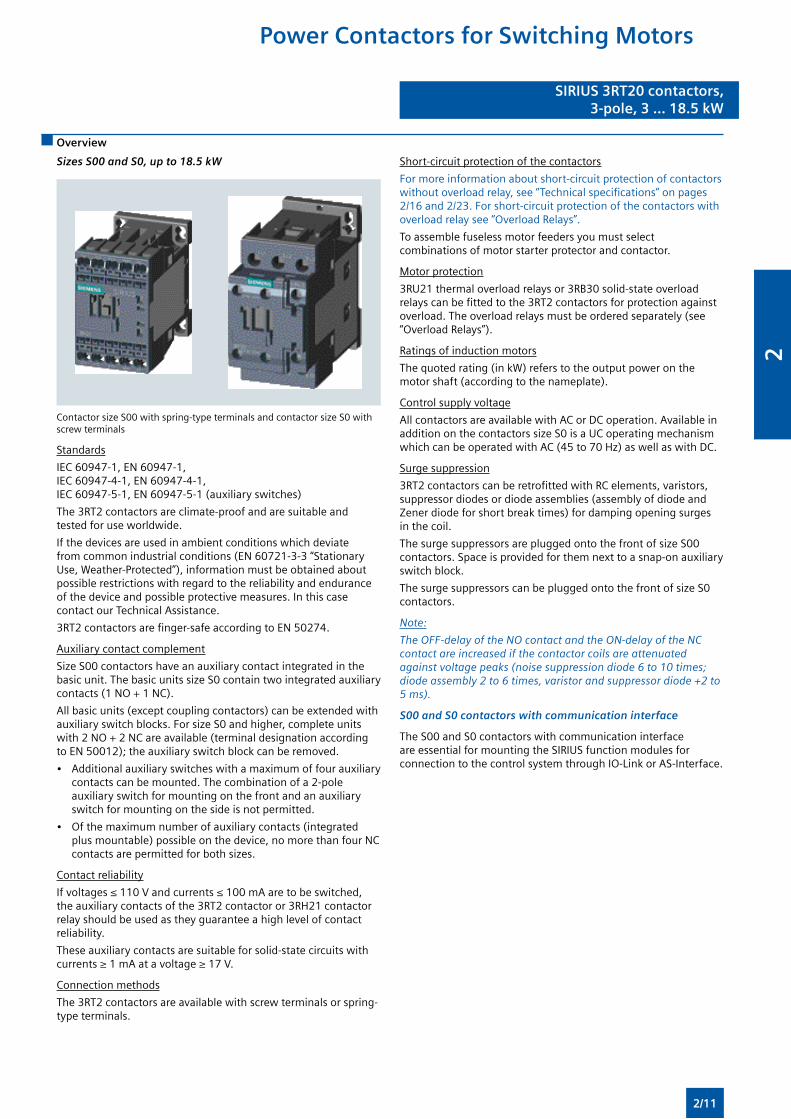
Sizes S00 and S0, up to 18.5 kW
Contactor size S00 with spring-type terminals and contactor size S0 with screw terminals
Standards
IEC 60947-1, EN 60947-1, IEC 60947-4-1, EN 60947-4-1, IEC 60947-5-1, EN 60947-5-1 (auxiliary switches)
The 3RT2 contactors are climate-proof and are suitable and tested for use worldwide.
If the devices are used in ambient conditions which deviate from common industrial conditions (EN 60721-3-3 “Stationary Use, Weather-Protected”), information must be obtained about possible restrictions with regard to the reliability and endurance of the device and possible protective measures. In this case contact our Technical Assistance.
3RT2 contactors are finger-safe according to EN 50274.
Auxiliary contact complement
Size S00 contactors have an auxiliary contact integrated in the basic unit. The basic units size S0 contain two integrated auxiliary contacts (1 NO + 1 NC).
All basic units (except coupling contactors) can be extended with auxiliary switch blocks. For size S0 and higher, complete units with 2 NO + 2 NC are available (terminal designation according to EN 50012); the auxiliary switch block can be removed.
• Additional auxiliary switches with a maximum of four auxiliary contacts can be mounted. The combination of a 2-pole auxiliary switch for mounting on the front and an auxiliary switch for mounting on the side is not permitted.
• Of the maximum number of auxiliary contacts (integrated plus mountable) possible on the device, no more than four NC contacts are permitted for both sizes.
Contact reliability
If voltages ≤ 110 V and currents ≤ 100 mA are to be switched, the auxiliary contacts of the 3RT2 contactor or 3RH21 contactor relay should be used as they guarantee a high level of contact reliability.
These auxiliary contacts are suitable for solid-state circuits with currents ≥ 1 mA at a voltage ≥ 17 V.
Connection methods
The 3RT2 contactors are available with screw terminals or spring-type terminals.
Short-circuit protection of the contactors
For more information about short-circuit protection of contactors without overload relay, see “Technical specifications” on pages 2/16 and 2/23. For short-circuit protection of the contactors with overload relay see “Overload Relays”.
To assemble fuseless motor feeders you must select combinations of motor starter protector and contactor.
Motor protection
3RU21 thermal overload relays or 3RB30 solid-state overload relays can be fitted to the 3RT2 contactors for protection against overload. The overload relays must be ordered separately (see “Overload Relays”).
Ratings of induction motors
The quoted rating (in kW) refers to the output power on the motor shaft (according to the nameplate).
Control supply voltage
All contactors are available with AC or DC operation. Available in addition on the contactors size S0 is a UC operating mechanism which can be operated with AC (45 to 70 Hz) as well as with DC.
Surge suppression
3RT2 contactors can be retrofitted with RC elements, varistors, suppressor diodes or diode assemblies (assembly of diode and Zener diode for short break times) for damping opening surges in the coil.
The surge suppressors are plugged onto the front of size S00 contactors. Space is provided for them next to a snap-on auxiliary switch block.
The surge suppressors can be plugged onto the front of size S0 contactors.
Note:
The OFF-delay of the NO contact and the ON-delay of the NC contact are increased if the contactor coils are attenuated against voltage peaks (noise suppression diode 6 to 10 times; diode assembly 2 to 6 times, varistor and suppressor diode +2 to 5 ms).
S00 and S0 contactors with communication interface
The S00 and S0 contactors with communication interface are essential for mounting the SIRIUS function modules for connection to the control system through IO-Link or AS-Interface.
Power Contactors for Switching Motors
2/11
2
Power Contactors for Switching Motors
SIRIUS 3RT20 contactors,3-pole, 3 ... 18.5 kW
SIRIUS 3RT20 contactors,3-pole, 3 ... 18.5 kW
Order No. scheme
Digit of the Order No. 1st - 3rd 4th 5th 6th 7th 8th 9th 10th 11th 12th 13th 14th 15th 16th
– –
SIRIUS power contactors 3 R T
Innovations 2
Device type (e. g. 0 = 3-pole motor contactor, 3 = 4-pole AC-1 contactor)
Contactor size (1 = S00, 2 = S0)
Power dependent on size (e. g. 27 = 15 kW)
Connection type (1 = screw, 2 = spring)
Operating range / solenoid coil circuit (e. g. A = AC standard / without)
Rated control supply voltage (e. g. P0 = 230 V, 50 Hz)
Auxiliary switches (e. g. S0: 0 = 1 NO + 1 NC integrated)
Special version
Example 3 R T 2 0 2 7 – 1 A P 0 0
Note: The Order No. scheme is presented here merely for information purposes and for better understanding of the logic behind the order numbers.
For your orders, please use the order numbers quote in the catalog in the Selection and ordering data.
Accessories
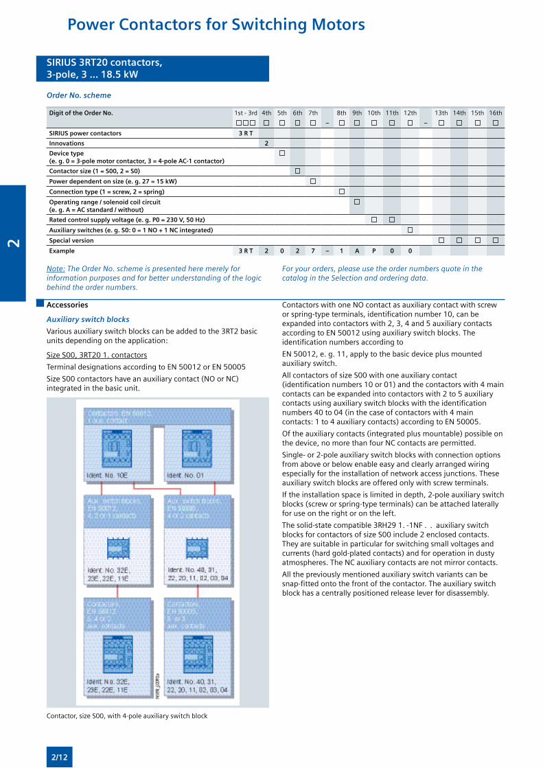
Auxiliary switch blocks
Various auxiliary switch blocks can be added to the 3RT2 basic units depending on the application:
Size S00, 3RT20 1. contactors
Terminal designations according to EN 50012 or EN 50005
Size S00 contactors have an auxiliary contact (NO or NC) integrated in the basic unit.
Contactors with one NO contact as auxiliary contact with screw or spring-type terminals, identification number 10, can be expanded into contactors with 2, 3, 4 and 5 auxiliary contacts according to EN 50012 using auxiliary switch blocks. The identification numbers according to
EN 50012, e. g. 11, apply to the basic device plus mounted auxiliary switch.
All contactors of size S00 with one auxiliary contact (identification numbers 10 or 01) and the contactors with 4 main contacts can be expanded into contactors with 2 to 5 auxiliary contacts using auxiliary switch blocks with the identification numbers 40 to 04 (in the case of contactors with 4 main contacts: 1 to 4 auxiliary contacts) according to EN 50005.
Of the auxiliary contacts (integrated plus mountable) possible on the device, no more than four NC contacts are permitted.
Single- or 2-pole auxiliary switch blocks with connection options from above or below enable easy and clearly arranged wiring especially for the installation of network access junctions. These auxiliary switch blocks are offered only with screw terminals.
If the installation space is limited in depth, 2-pole auxiliary switch blocks (screw or spring-type terminals) can be attached laterally for use on the right or on the left.
The solid-state compatible 3RH29 1. -1NF . . auxiliary switch blocks for contactors of size S00 include 2 enclosed contacts. They are suitable in particular for switching small voltages and currents (hard gold-plated contacts) and for operation in dusty atmospheres. The NC auxiliary contacts are not mirror contacts.
All the previously mentioned auxiliary switch variants can be snap-fitted onto the front of the contactor. The auxiliary switch block has a centrally positioned release lever for disassembly.
Contactor, size S00, with 4-pole auxiliary switch block
2/12
2
SIRIUS 3RT20 contactors,3-pole, 3 ... 18.5 kW
SIRIUS 3RT20 contactors,3-pole, 3 ... 18.5 kW
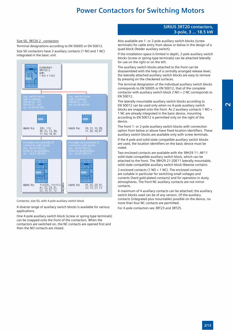
Size S0, 3RT20 2 . contactors
Terminal designations according to EN 50005 or EN 50012.
Size S0 contactors have 2 auxiliary contacts (1 NO and 1 NC) integrated in the basic unit.
Contactor, size S0, with 4-pole auxiliary switch block
A diverse range of auxiliary switch blocks is available for various applications.
One 4-pole auxiliary switch block (screw or spring-type terminals) can be snapped onto the front of the contactors. When the contactors are switched on, the NC contacts are opened first and then the NO contacts are closed.
Also available are 1- or 2-pole auxiliary switch blocks (screw terminals) for cable entry from above or below in the design of a quad block (feeder auxiliary switch).
If the installation space is limited in depth, 2-pole auxiliary switch blocks (screw or spring-type terminals) can be attached laterally for use on the right or on the left.
The auxiliary switch blocks attached to the front can be disassembled with the help of a centrally arranged release lever; the laterally attached auxiliary switch blocks are easy to remove by pressing on the checkered surfaces.
The terminal designation of the individual auxiliary switch blocks corresponds to EN 50005 or EN 50012, that of the complete contactor with auxiliary switch block 2 NO + 2 NC corresponds to EN 50012.
The laterally mountable auxiliary switch blocks according to EN 50012 can be used only when no 4-pole auxiliary switch blocks are snapped onto the front. As 2 auxiliary contacts 1 NO + 1 NC are already integrated in the basic device, mounting according to EN 50012 is permitted only on the right of the device.
The front 1- or 2-pole auxiliary switch blocks with connection option from below or above have fixed location identifiers. These auxiliary switch blocks are available only with screw terminals.
If the 4-pole and solid-state compatible auxiliary switch blocks are used, the location identifiers on the basic device must be noted.
Two enclosed contacts are available with the 3RH29 11-.NF11 solid-state compatible auxiliary switch block, which can be attached to the front. The 3RH29 21-2DE11 laterally mountable, solid-state compatible auxiliary switch block likewise contains
2 enclosed contacts (1 NO + 1 NC). The enclosed contacts are suitable in particular for switching small voltages and currents (hard gold-plated contacts) and for operation in dusty atmospheres. The front NC auxiliary contacts are not mirror contacts.
A maximum of 4 auxiliary contacts can be attached; the auxiliary switch blocks used can be of any version. Of the auxiliary contacts (integrated plus mountable) possible on the device, no more than four NC contacts are permitted.
For 4-pole contactors see 3RT23 and 3RT25.
Power Contactors for Switching Motors
2/13
2
Power Contactors for Switching Motors
SIRIUS 3RT20 contactors,3-pole, 3 ... 18.5 kW
SIRIUS 3RT20 contactors,3-pole, 3 ... 18.5 kW
Technical specifications
Contactor TypeSize
3RT2S00 and S0
Rated data of the auxiliary contacts
Acc. to IEC 60947-5-1/EN 60947-5-1The data apply to integrated auxiliary contacts and contacts in the auxiliary switch blocks for contactor sizes S00 to S01)
Rated insulation voltage Ui (pollution degree 3) V 690
Conventional thermal current Ith = Rated operational current Ie/AC-12
A 10
AC load
Rated operational current Ie/AC-15/AC-14
• For rated operational voltage Ue 24 V110 V125 V220 V230 V
AAAAA
101)
101)
101)
101)
101)
380 V415 V500 V660 V690 V
AAAAA
33211
DC load
Rated operational current Ie/DC-12
• For rated operational voltage Ue 24 V60 V
110 V125 V
AAAA
6632
220 V440 V600 V
AAA
10.30.15
Rated operational current Ie/DC-13
• For rated operational voltage Ue 24 V60 V
110 V125 V
AAAA
6210.9
220 V440 V600 V
AAA
0.30.140.1
Contact reliability at 17 V, 1 mA Acc. to EN 60947-5-4
Frequency of contact faults < 10-8 i. e. <1 fault per 100 million operating cycles
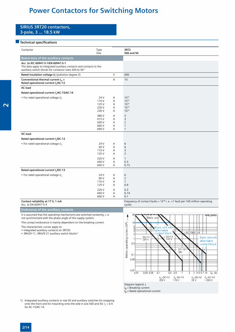
Endurance of the auxiliary contacts
It is assumed that the operating mechanisms are switched randomly, i. e. not synchronized with the phase angle of the supply system.
The contact endurance is mainly dependent on the breaking current.
The characteristic curves apply to:• Integrated auxiliary contacts on 3RT20• 3RH29 11, 3RH29 21 auxiliary switch blocks1)
Diagram legend: | Ia = Breaking current Ie = Rated operational current
1) Integrated auxiliary contacts in size S0 and auxiliary switches for snapping onto the front and for mounting onto the side in size S00 and S0: Ie = 6 A for AC-15/AC-14.
2/14
2
SIRIUS 3RT20 contactors,3-pole, 3 ... 18.5 kW
SIRIUS 3RT20 contactors,3-pole, 3 ... 18.5 kW
Contactor Type
Size
3RT2
S00 and S0
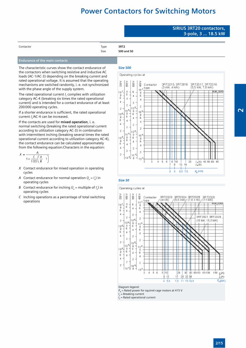
Endurance of the main contacts
The characteristic curves show the contact endurance of the contactors when switching resistive and inductive AC loads (AC-1/AC-3) depending on the breaking current and rated operational voltage. It is assumed that the operating mechanisms are switched randomly, i. e. not synchronized with the phase angle of the supply system.
The rated operational current Ie complies with utilization category AC-4 (breaking six times the rated operational current) and is intended for a contact endurance of at least 200 000 operating cycles.
If a shorter endurance is sufficient, the rated operational current Ie/AC-4 can be increased.
If the contacts are used for mixed operation, i. e. normal switching (breaking the rated operational current according to utilization category AC-3) in combination with intermittent inching (breaking several times the rated operational current according to utilization category AC-4), the contact endurance can be calculated approximately from the following equation:Characters in the equation:
X Contact endurance for mixed operation in operating cycles
A Contact endurance for normal operation (Ia = Ie) in operating cycles
B Contact endurance for inching (Ia = multiple of Ie) in operating cycles
C Inching operations as a percentage of total switching operations
Size S00
Size S0
Diagram legend: PN = Rated power for squirrel-cage motors at 415 V Ia = Breaking current Ie = Rated operational current
Power Contactors for Switching Motors
2/15
2
Power Contactors for Switching Motors
SIRIUS 3RT20 contactors,3-pole, 3 ... 18.5 kW
SIRIUS 3RT20 contactors,3-pole, 3 ... 18.5 kW
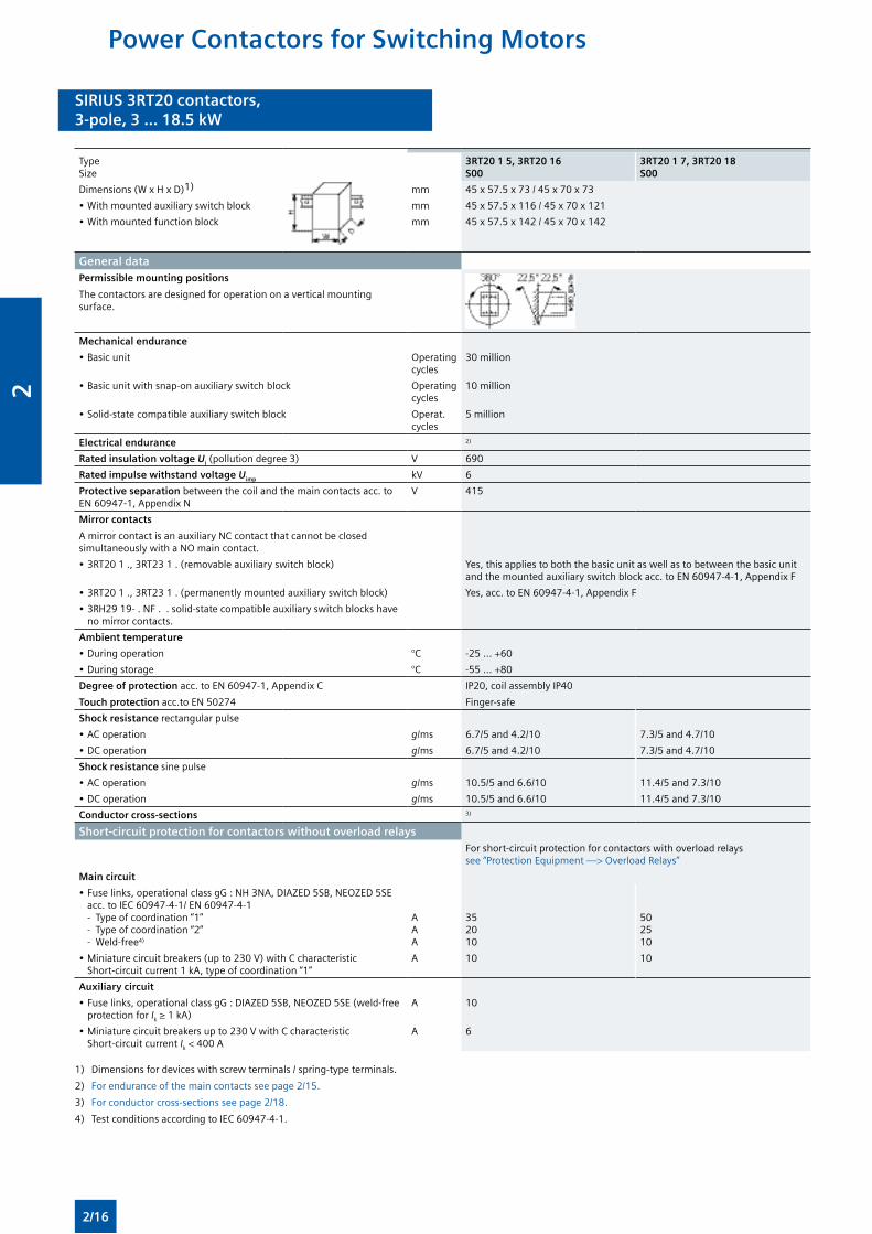
TypeSize
3RT20 1 5, 3RT20 16S00
3RT20 1 7, 3RT20 18S00
Dimensions (W x H x D)1) mm 45 x 57.5 x 73 / 45 x 70 x 73
• With mounted auxiliary switch block mm 45 x 57.5 x 116 / 45 x 70 x 121
• With mounted function block mm 45 x 57.5 x 142 / 45 x 70 x 142
General dataPermissible mounting positions
The contactors are designed for operation on a vertical mounting surface.
Mechanical endurance
• Basic unit Operating cycles
30 million
• Basic unit with snap-on auxiliary switch block Operating cycles
10 million
• Solid-state compatible auxiliary switch block Operat. cycles
5 million
Electrical endurance 2)
Rated insulation voltage Ui (pollution degree 3) V 690
Rated impulse withstand voltage Uimp kV 6
Protective separation between the coil and the main contacts acc. to EN 60947-1, Appendix N
V 415
Mirror contacts
A mirror contact is an auxiliary NC contact that cannot be closed simultaneously with a NO main contact.
• 3RT20 1 ., 3RT23 1 . (removable auxiliary switch block) Yes, this applies to both the basic unit as well as to between the basic unit and the mounted auxiliary switch block acc. to EN 60947-4-1, Appendix F
• 3RT20 1 ., 3RT23 1 . (permanently mounted auxiliary switch block) Yes, acc. to EN 60947-4-1, Appendix F
• 3RH29 19- . NF . . solid-state compatible auxiliary switch blocks have no mirror contacts.
Ambient temperature
• During operation °C -25 ... +60
• During storage °C -55 ... +80
Degree of protection acc. to EN 60947-1, Appendix C
Touch protection acc.to EN 50274
IP20, coil assembly IP40
Finger-safe
Shock resistance rectangular pulse
• AC operation g/ms 6.7/5 and 4.2/10 7.3/5 and 4.7/10
• DC operation g/ms 6.7/5 and 4.2/10 7.3/5 and 4.7/10
Shock resistance sine pulse
• AC operation g/ms 10.5/5 and 6.6/10 11.4/5 and 7.3/10
• DC operation g/ms 10.5/5 and 6.6/10 11.4/5 and 7.3/10
Conductor cross-sections 3)
Short-circuit protection for contactors without overload relaysFor short-circuit protection for contactors with overload relays see “Protection Equipment —> Overload Relays”
Main circuit
• Fuse links, operational class gG : NH 3NA, DIAZED 5SB, NEOZED 5SE acc. to IEC 60947-4-1/ EN 60947-4-1
- Type of coordination “1” - Type of coordination “2” - Weld-free4)
AAA
35 2010
502510
• Miniature circuit breakers (up to 230 V) with C characteristic Short-circuit current 1 kA, type of coordination “1”
A 10 10
Auxiliary circuit
• Fuse links, operational class gG : DIAZED 5SB, NEOZED 5SE (weld-free protection for Ik ≥ 1 kA)
A 10
• Miniature circuit breakers up to 230 V with C characteristic Short-circuit current Ik < 400 A
A 6
1) Dimensions for devices with screw terminals / spring-type terminals.
2) For endurance of the main contacts see page 2/15.
3) For conductor cross-sections see page 2/18.
4) Test conditions according to IEC 60947-4-1.
2/16
2
SIRIUS 3RT20 contactors,3-pole, 3 ... 18.5 kW
SIRIUS 3RT20 contactors,3-pole, 3 ... 18.5 kW
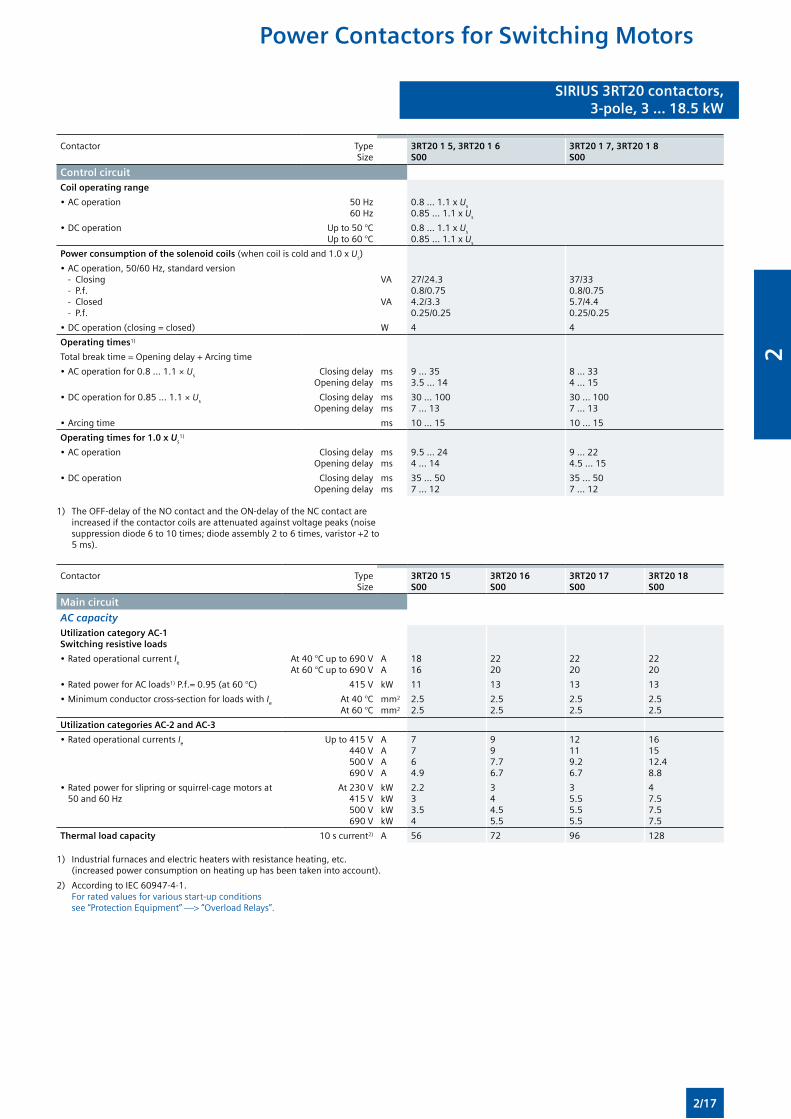
Contactor TypeSize
3RT20 1 5, 3RT20 1 6S00
3RT20 1 7, 3RT20 1 8S00
Control circuitCoil operating range
• AC operation 50 Hz 60 Hz
0.8 ... 1.1 x Us
0.85 ... 1.1 x Us
• DC operation Up to 50 °CUp to 60 °C
0.8 ... 1.1 x Us
0.85 ... 1.1 x Us
Power consumption of the solenoid coils (when coil is cold and 1.0 x Us)
• AC operation, 50/60 Hz, standard version - Closing - P.f. - Closed - P.f.
VA VA
27/24.30.8/0.754.2/3.30.25/0.25
37/330.8/0.755.7/4.40.25/0.25
• DC operation (closing = closed) W 4 4
Operating times1)
Total break time = Opening delay + Arcing time
• AC operation for 0.8 ... 1.1 × Us Closing delayOpening delay
msms
9 ... 353.5 ... 14
8 ... 334 ... 15
• DC operation for 0.85 ... 1.1 × Us Closing delayOpening delay
msms
30 ... 1007 ... 13
30 ... 1007 ... 13
• Arcing time ms 10 ... 15 10 ... 15
Operating times for 1.0 x Us1)
• AC operation Closing delayOpening delay
msms
9.5 ... 244 ... 14
9 ... 224.5 ... 15
• DC operation Closing delayOpening delay
msms
35 ... 507 ... 12
35 ... 507 ... 12
1) The OFF-delay of the NO contact and the ON-delay of the NC contact are increased if the contactor coils are attenuated against voltage peaks (noise suppression diode 6 to 10 times; diode assembly 2 to 6 times, varistor +2 to 5 ms).
Contactor TypeSize
3RT20 15S00
3RT20 16S00
3RT20 17S00
3RT20 18S00
Main circuit
AC capacityUtilization category AC-1 Switching resistive loads
• Rated operational current Ie At 40 °C up to 690 VAt 60 °C up to 690 V
AA
1816
2220
2220
2220
• Rated power for AC loads1) P.f.= 0.95 (at 60 °C) 415 V kW 11 13 13 13
• Minimum conductor cross-section for loads with Ie At 40 °CAt 60 °C
mm2
mm2
2.52.5
2.52.5
2.52.5
2.52.5
Utilization categories AC-2 and AC-3
• Rated operational currents Ie Up to 415 V440 V500 V690 V
AAAA
7764.9
997.76.7
12119.26.7
161512.48.8
• Rated power for slipring or squirrel-cage motors at 50 and 60 Hz
At 230 V415 V500 V690 V
kWkWkWkW
2.233.54
344.55.5
35.55.55.5
47.57.57.5
Thermal load capacity 10 s current2) A 56 72 96 128
1) Industrial furnaces and electric heaters with resistance heating, etc. (increased power consumption on heating up has been taken into account).
2) According to IEC 60947-4-1. For rated values for various start-up conditions see “Protection Equipment” —> “Overload Relays”.
Power Contactors for Switching Motors
2/17
2
Power Contactors for Switching Motors
SIRIUS 3RT20 contactors,3-pole, 3 ... 18.5 kW
SIRIUS 3RT20 contactors,3-pole, 3 ... 18.5 kW
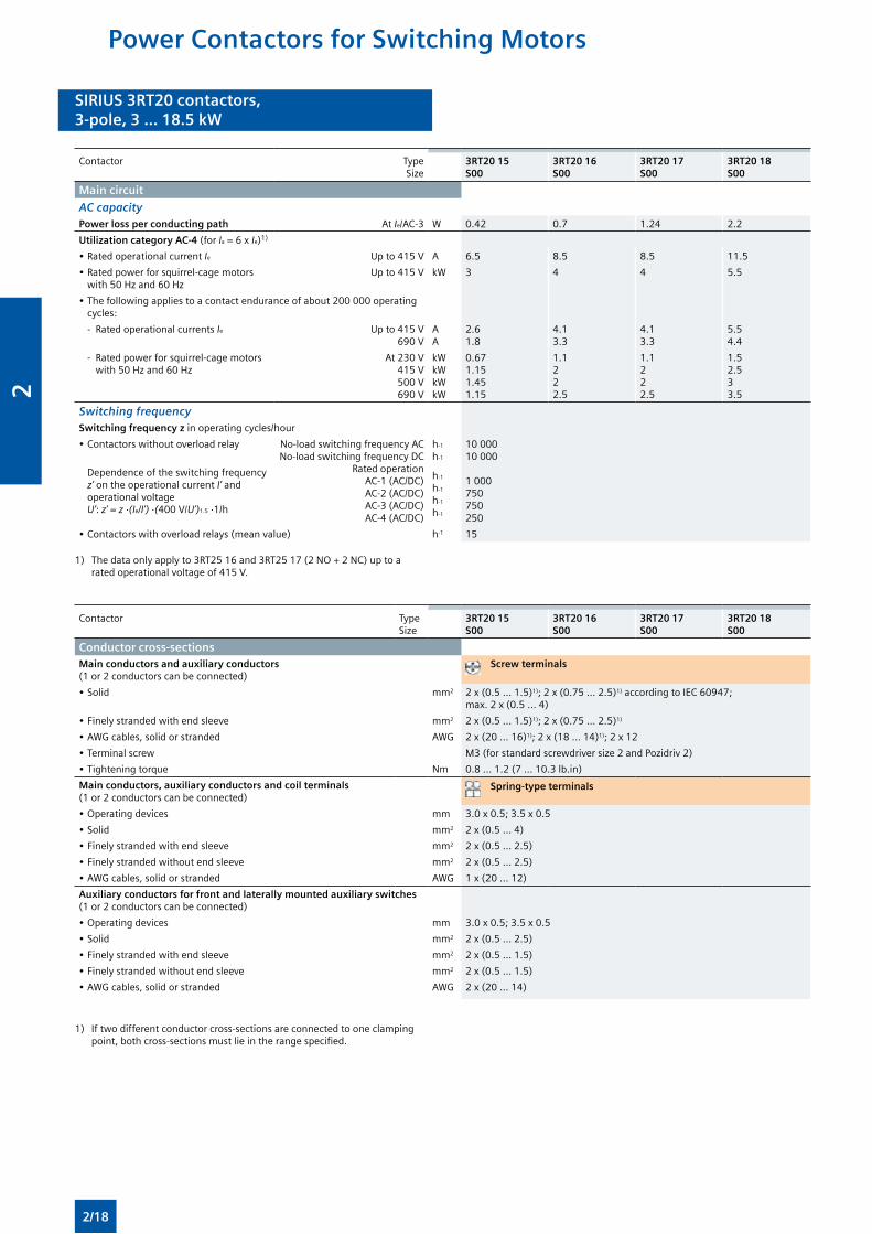
Contactor TypeSize
3RT20 15S00
3RT20 16S00
3RT20 17S00
3RT20 18S00
Main circuit
AC capacityPower loss per conducting path At Ie/AC-3 W 0.42 0.7 1.24 2.2
Utilization category AC-4 (for Ia = 6 x Ie)1)
• Rated operational current Ie Up to 415 V A 6.5 8.5 8.5 11.5
• Rated power for squirrel-cage motors with 50 Hz and 60 Hz
Up to 415 V kW 3 4 4 5.5
• The following applies to a contact endurance of about 200 000 operating cycles:
- Rated operational currents Ie Up to 415 V690 V
AA
2.61.8
4.13.3
4.13.3
5.54.4
- Rated power for squirrel-cage motors with 50 Hz and 60 Hz
At 230 V415 V500 V690 V
kWkWkWkW
0.671.151.451.15
1.1222.5
1.1222.5
1.52.533.5
Switching frequency Switching frequency z in operating cycles/hour
• Contactors without overload relay No-load switching frequency ACNo-load switching frequency DC
Rated operationAC-1 (AC/DC)AC-2 (AC/DC)AC-3 (AC/DC)AC-4 (AC/DC)
h-1
h-1
h-1
h-1
h-1
h-1
10 00010 000
1 000750750250
Dependence of the switching frequency z’ on the operational current I’ and operational voltage U’: z’ = z ·(Ie/I’) ·(400 V/U’)1.5 ·1/h
• Contactors with overload relays (mean value) h-1 15
1) The data only apply to 3RT25 16 and 3RT25 17 (2 NO + 2 NC) up to a rated operational voltage of 415 V.
Contactor TypeSize
3RT20 15S00
3RT20 16S00
3RT20 17S00
3RT20 18S00
Conductor cross-sections Main conductors and auxiliary conductors (1 or 2 conductors can be connected)
Screw terminals
• Solid mm2 2 x (0.5 ... 1.5)1); 2 x (0.75 ... 2.5)1) according to IEC 60947; max. 2 x (0.5 ... 4)
• Finely stranded with end sleeve mm2 2 x (0.5 ... 1.5)1); 2 x (0.75 ... 2.5)1)
• AWG cables, solid or stranded AWG 2 x (20 ... 16)1); 2 x (18 ... 14)1); 2 x 12
• Terminal screw M3 (for standard screwdriver size 2 and Pozidriv 2)
• Tightening torque Nm 0.8 ... 1.2 (7 ... 10.3 lb.in)
Main conductors, auxiliary conductors and coil terminals (1 or 2 conductors can be connected)
Spring-type terminals
• Operating devices mm 3.0 x 0.5; 3.5 x 0.5
• Solid mm2 2 x (0.5 ... 4)
• Finely stranded with end sleeve mm2 2 x (0.5 ... 2.5)
• Finely stranded without end sleeve mm2 2 x (0.5 ... 2.5)
• AWG cables, solid or stranded AWG 1 x (20 ... 12)
Auxiliary conductors for front and laterally mounted auxiliary switches (1 or 2 conductors can be connected)
• Operating devices mm 3.0 x 0.5; 3.5 x 0.5
• Solid mm2 2 x (0.5 ... 2.5)
• Finely stranded with end sleeve mm2 2 x (0.5 ... 1.5)
• Finely stranded without end sleeve mm2 2 x (0.5 ... 1.5)
• AWG cables, solid or stranded AWG 2 x (20 ... 14)
1) If two different conductor cross-sections are connected to one clamping point, both cross-sections must lie in the range specified.
2/18
2
SIRIUS 3RT20 contactors,3-pole, 3 ... 18.5 kW
SIRIUS 3RT20 contactors,3-pole, 3 ... 18.5 kW
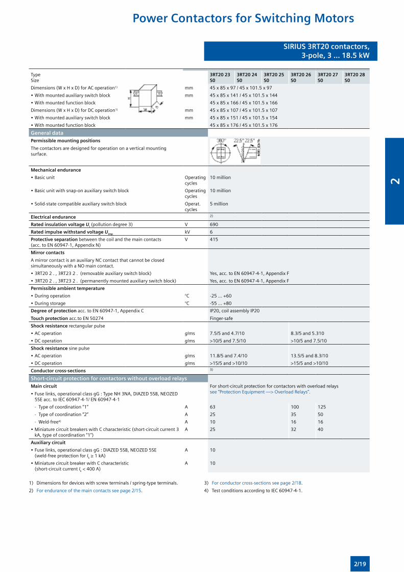
TypeSize
3RT20 23S0
3RT20 24S0
3RT20 25S0
3RT20 26S0
3RT20 27S0
3RT20 28S0
Dimensions (W x H x D) for AC operation1) mm 45 x 85 x 97 / 45 x 101.5 x 97
• With mounted auxiliary switch block mm 45 x 85 x 141 / 45 x 101.5 x 144
• With mounted function block 45 x 85 x 166 / 45 x 101.5 x 166
Dimensions (W x H x D) for DC operation1) mm 45 x 85 x 107 / 45 x 101.5 x 107
• With mounted auxiliary switch block mm 45 x 85 x 151 / 45 x 101.5 x 154
• With mounted function block 45 x 85 x 176 / 45 x 101.5 x 176
General dataPermissible mounting positions
The contactors are designed for operation on a vertical mounting surface.
Mechanical endurance
• Basic unit Operating cycles
10 million
• Basic unit with snap-on auxiliary switch block Operating cycles
10 million
• Solid-state compatible auxiliary switch block Operat. cycles
5 million
Electrical endurance 2)
Rated insulation voltage Ui (pollution degree 3) V 690
Rated impulse withstand voltage Uimp kV 6
Protective separation between the coil and the main contacts (acc. to EN 60947-1, Appendix N)
V 415
Mirror contacts
A mirror contact is an auxiliary NC contact that cannot be closed simultaneously with a NO main contact.
• 3RT20 2 . , 3RT23 2 . (removable auxiliary switch block) Yes, acc. to EN 60947-4-1, Appendix F
• 3RT20 2 . , 3RT23 2 . (permanently mounted auxiliary switch block) Yes, acc. to EN 60947-4-1, Appendix F
Permissible ambient temperature
• During operation °C -25 ... +60
• During storage °C -55 ... +80
Degree of protection acc. to EN 60947-1, Appendix C
Touch protection acc.to EN 50274
IP20, coil assembly IP20
Finger-safe
Shock resistance rectangular pulse
• AC operation g/ms 7.5/5 and 4.7/10 8.3/5 and 5.310
• DC operation g/ms >10/5 and 7.5/10 >10/5 and 7.5/10
Shock resistance sine pulse
• AC operation g/ms 11.8/5 and 7.4/10 13.5/5 and 8.3/10
• DC operation g/ms >15/5 and >10/10 >15/5 and >10/10
Conductor cross-sections 3)
Short-circuit protection for contactors without overload relaysMain circuit
• Fuse links, operational class gG : Type NH 3NA, DIAZED 5SB, NEOZED 5SE acc. to IEC 60947-4-1/ EN 60947-4-1
For short-circuit protection for contactors with overload relays see “Protection Equipment —> Overload Relays”.
- Type of coordination “1” A 63 100 125
- Type of coordination “2” A 25 35 50
- Weld-free4) A 10 16 16
• Miniature circuit breakers with C characteristic (short-circuit current 3 kA, type of coordination “1”)
A 25 32 40
Auxiliary circuit
• Fuse links, operational class gG : DIAZED 5SB, NEOZED 5SE (weld-free protection for Ik ≥ 1 kA)
A 10
• Miniature circuit breaker with C characteristic (short-circuit current Ik < 400 A)
A 10
1) Dimensions for devices with screw terminals / spring-type terminals.
2) For endurance of the main contacts see page 2/15.
3) For conductor cross-sections see page 2/18.
4) Test conditions according to IEC 60947-4-1.
Power Contactors for Switching Motors
2/19
2
Power Contactors for Switching Motors
SIRIUS 3RT20 contactors,3-pole, 3 ... 18.5 kW
SIRIUS 3RT20 contactors,3-pole, 3 ... 18.5 kW
Contactor Type
Size
3RT20 23 ... 3RT20 25
S0
3RT20 26 ... 3RT20 28
S0
3RT20 2. -.NB3
S0
3RT20 2. -.NF3..
S0
3RT20 2. -.NP3
S0
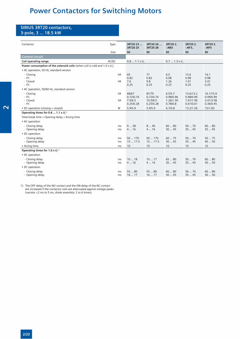
Control circuitCoil operating range AC/DC 0.8 ... 1.1 x Us 0.7 ... 1.3 x Us
Power consumption of the solenoid coils (when coil is cold and 1.0 x Us)
• AC operation, 50 Hz, standard version
- Closing - P.f. - Closed - P.f.
VA VA
650.827.60.25
770.829.80.25
6.50.981.260.25
13.60.981.910.25
16.10.983.410.25
• AC operation, 50/60 Hz, standard version
- Closing - P.f. - Closed - P.f.
VA VA
68/670.72/0.747.9/6.50.25/0.28
81/790.72/0.7410.5/8.50.25/0.28
6.5/5.70.98/0.961.26/1.300.78/0.8
13.6/13.20.98/0.991.91/1.900.61/0.61
16.1/15.90.99/0.993.41/3.580.36/0.45
• DC operation (closing = closed) W 5.9/5.9 5.9/5.9 6.7/0.8 13.2/1.56 15/1.83
Operating times for 0.8 ... 1.1 x Us1)
Total break time = Opening delay + Arcing time
• AC operation
- Closing delay - Opening delay
msms
9 ... 384 ... 16
8 ... 404 ... 16
60 ... 8030 ... 45
50 ... 7035 ... 45
60 ... 8035 ... 45
• DC operation
- Closing delay - Opening delay
msms
50 ... 17015 ... 17.5
50 ... 17015 ... 17.5
60 ... 7530 ... 45
50 ... 7035 ... 45
50 ... 7540 ... 50
• Arcing time ms 10 10 10 10 10
Operating times for 1.0 x Us1)
• AC operation
- Closing delay - Opening delay
msms
10 ... 184 ... 16
10 ... 174 ... 16
65 ... 8030 ... 45
50 ... 7035 ... 45
60 ... 8030 ... 50
• DC operation
- Closing delay - Opening delay
msms
55 ... 8016 ... 17
55 ... 8016 ... 17
60 ... 8030 ... 45
56 ... 7035 ... 45
60 ... 8030 ... 50
1) The OFF-delay of the NO contact and the ON-delay of the NC contact are increased if the contactor coils are attenuated against voltage peaks (varistor +2 ms to 5 ms, diode assembly: 2 to 6 times).
2/20
2
SIRIUS 3RT20 contactors,3-pole, 3 ... 18.5 kW
SIRIUS 3RT20 contactors,3-pole, 3 ... 18.5 kW
Contactor Type
Size
3RT20 23
S0
3RT20 24
S0
3RT20 25
S0
3RT20 26
S0
3RT20 27
S0
3RT20 28
S0
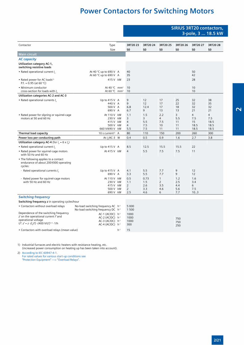
Main circuit
AC capacityUtilization category AC-1, switching resistive loads
• Rated operational current Ie At 40 °C up to 690 VAt 60 °C up to 690 V
AA
4035
5042
• Rated power for AC loads1)
P.f. = 0.95 (at 60 °C)415 V kW 23 28
• Minimum conductor cross-section for loads with Ie
At 40 °CAt 60 °C
mm2
mm2
1010
1010
Utilization categories AC-2 and AC-3
• Rated operational currents Ie Up to 415 V440 V500 V690 V
AAAA
996.86.7
121212.49
17171713
25221813
32323221
38353221
• Rated power for slipring or squirrel-cage motors at 50 and 60 Hz
At 110 V230 V415 V500 V
660 V/690 V
kWkWkWkWkW
1.13445.5
1.535.57.57.5
2.247.51011
35.5111111
47.51518.518.5
47.518.518.518.5
Thermal load capacity 10 s current2) A 80 110 150 200 260 300
Power loss per conducting path At Ie/AC-3 W 0.4 0.5 0.9 1.6 2.7 3.8
Utilization category AC-4 (for Ia = 6 x Ie)
• Rated operational current Ie Up to 415 V A 8.5 12.5 15.5 15.5 22
• Rated power for squirrel-cage motors with 50 Hz and 60 Hz
At 415 V kW 4 5.5 7.5 7.5 11
• The following applies to a contact endurance of about 200†000 operating cycles:
- Rated operational currents Ie Up to 415 V690 V
AA
4.13.3
5.55.5
7.77.7
99
1212
- Rated power for squirrel-cage motors with 50 Hz and 60 Hz
At 110 V230 V415 V500 V690 V
kWkWkWkWkW
0.51.1222.5
0.731.52.63.34.6
123.54.66
1.22.54.45.67.7
1.63.467.510..3
Switching frequencySwitching frequency z in operating cycles/hour
• Contactors without overload relays
Dependence of the switching frequency z’ on the operational current I’ and operational voltage U’: z’ = z ·(Ie/I’) ·(400 V/U’)1.5 ·1/h
No-load switching frequency ACNo-load switching frequency DC
h-1
h-1
5 0001 500
AC-1 (AC/DC)AC-2 (AC/DC)AC-3 (AC/DC)AC-4 (AC/DC)
h-1
h-1
h-1
h-1
100010001000300
750750250
• Contactors with overload relays (mean value) h-1 15
1) Industrial furnaces and electric heaters with resistance heating, etc. (increased power consumption on heating up has been taken into account).
2) According to IEC 60947-4-1. For rated values for various start-up conditions see “Protection Equipment” —> “Overload Relays”.
Power Contactors for Switching Motors
2/21
2
Power Contactors for Switching Motors
SIRIUS 3RT20 contactors,3-pole, 3 ... 18.5 kW
SIRIUS 3RT20 contactors,3-pole, 3 ... 18.5 kW
Contactor Type
Size
3RT20 23
S0
3RT20 24
S0
3RT20 25
S0
3RT20 26
S0
3RT20 27
S0
3RT20 28
S0
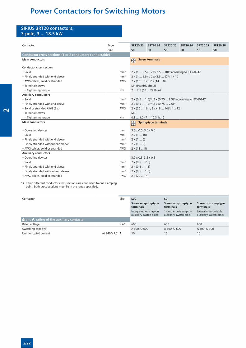
Conductor cross-sections (1 or 2 conductors connectable)Main conductors Screw terminals
Conductor cross-section
• Solid mm² 2 x (1 ... 2.5)1); 2 x (2.5 ... 10)1) according to IEC 60947
• Finely stranded with end sleeve mm² 2 x (1 ... 2.5)1); 2 x (2.5 ... 6)1); 1 x 10
• AWG cables, solid or stranded AWG 2 x (16 ... 12); 2 x (14 ... 8)
• Terminal screws M4 (Pozidriv size 2)
- Tightening torque Nm 2 ... 2.5 (18 ... 22 lb.in)
Auxiliary conductors
• Solid mm2 2 x (0.5 ... 1.5)1); 2 x (0.75 ... 2.5)1) according to IEC 60947
• Finely stranded with end sleeve mm2 2 x (0.5 ... 1.5)1); 2 x (0.75 ... 2.5)1)
• Solid or stranded AWG (2 x) AWG 2 x (20 ... 16)1); 2 x (18 ... 14)1); 1 x 12
• Terminal screws M3
- Tightening torque Nm 0.8 ... 1.2 (7 ... 10.3 lb.in)
Main conductors Spring-type terminals
• Operating devices mm 3.0 x 0.5; 3.5 x 0.5
• Solid mm2 2 x (1 ... 10)
• Finely stranded with end sleeve mm2 2 x (1 ... 6)
• Finely stranded without end sleeve mm2 2 x (1 ... 6)
• AWG cables, solid or stranded AWG 2 x (18 ... 8)
Auxiliary conductors
• Operating devices 3.0 x 0.5; 3.5 x 0.5
• Solid mm2 2 x (0.5 ... 2.5)
• Finely stranded with end sleeve mm2 2 x (0.5 ... 1.5)
• Finely stranded without end sleeve mm2 2 x (0.5 ... 1.5)
• AWG cables, solid or stranded AWG 2 x (20 ... 14)
1) If two different conductor cross-sections are connected to one clamping point, both cross-sections must lie in the range specified.
Contactor Size S00 S0
Screw or spring-type terminals
Screw or spring-type terminals
Screw or spring-type terminals
Integrated or snap-on auxiliary switch block
1- and 4-pole snap-on auxiliary switch block
Laterally mountable auxiliary switch block
and rating of the auxiliary contactsRated voltage V AC 600 600 600
Switching capacity A 600, Q 600 A 600, Q 600 A 300, Q 300
Uninterrupted current At 240 V AC A 10 10 10
2/22
2
SIRIUS 3RT20 contactors,3-pole, 3 ... 18.5 kW
SIRIUS 3RT20 contactors,3-pole, 3 ... 18.5 kW
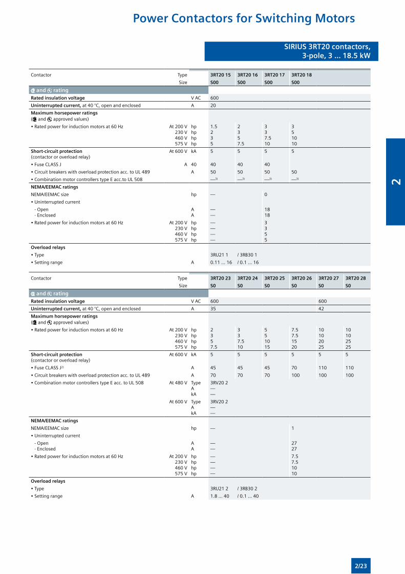
Contactor Type 3RT20 15 3RT20 16 3RT20 17 3RT20 18
Size S00 S00 S00 S00
and ratingRated insulation voltage V AC 600
Uninterrupted current, at 40 °C, open and enclosed A 20
Maximum horsepower ratings ( and approved values)
• Rated power for induction motors at 60 Hz At 200 V230 V460 V575 V
hphphphp
1.5235
2357.5
337.510
351010
Short-circuit protection(contactor or overload relay)
At 600 V kA 5 5 5 5
• Fuse CLASS J A 40 40 40 40
• Circuit breakers with overload protection acc. to UL 489 A 50 50 50 50
• Combination motor controllers type E acc.to UL 508 —3) —3) —3) —3)
NEMA/EEMAC ratings
NEMA/EEMAC size hp — 0
• Uninterrupted current
- Open - Enclosed
AA
——
1818
• Rated power for induction motors at 60 Hz At 200 V230 V460 V575 V
hphphphp
————
3355
Overload relays
• Type 3RU21 1 / 3RB30 1
• Setting range A 0.11 ... 16 / 0.1 ... 16
Contactor Type 3RT20 23 3RT20 24 3RT20 25 3RT20 26 3RT20 27 3RT20 28
Size S0 S0 S0 S0 S0 S0
and ratingRated insulation voltage V AC 600 600
Uninterrupted current, at 40 °C, open and enclosed A 35 42
Maximum horsepower ratings ( and approved values)
• Rated power for induction motors at 60 Hz At 200 V230 V460 V575 V
hphphphp
2357.5
337.510
551015
7.57.51520
10102025
10102525
Short-circuit protection(contactor or overload relay)
At 600 V kA 5 5 5 5 5 5
• Fuse CLASS J2) A 45 45 45 70 110 110
• Circuit breakers with overload protection acc. to UL 489 A 70 70 70 100 100 100
• Combination motor controllers type E acc. to UL 508 At 480 V TypeAkA
3RV20 2——
At 600 V TypeAkA
3RV20 2——
NEMA/EEMAC ratings
NEMA/EEMAC size hp — 1
• Uninterrupted current
- Open - Enclosed
AA
——
2727
• Rated power for induction motors at 60 Hz At 200 V230 V460 V575 V
hphphphp
————
7.57.51010
Overload relays
• Type 3RU21 2 / 3RB30 2
• Setting range A 1.8 ... 40 / 0.1 ... 40
Power Contactors for Switching Motors
2/23
2
SIRIUS 3RT20 contactors,3-pole, 3 ... 18.5 kW
SIRIUS 3RT20 contactors,3-pole, 3 ... 18.5 kW
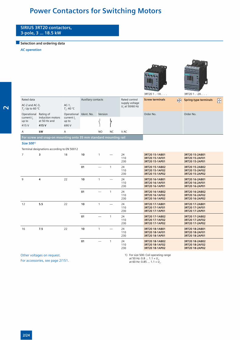
Selection and ordering data
AC operation
3RT20 1 . -1A . . . 3RT20 1 . -2A . . .
Rated data Auxiliary contacts Rated control supply voltage Us at 50/60 Hz
Screw terminals Spring-type terminals
AC-2 and AC-3, Tu: Up to 60 °C
AC-1, Tu: 40 °C
Operational current Ie up to
415 V
Rating of induction motors at 50 Hz and
415 V
Operational current Ie up to
690 V
Ident. No. Version Order No. Order No.
A kW A NO NC V AC
For screw and snap-on mounting onto 35 mm standard mounting rail
Size S001)
Terminal designations according to EN 50012
7 3 18 10 1 — 24110230
3RT20 15-1AB013RT20 15-1AF013RT20 15-1AP01
3RT20 15-2AB013RT20 15-2AF013RT20 15-2AP01
01 — 1 24110230
3RT20 15-1AB023RT20 15-1AF023RT20 15-1AP02
3RT20 15-2AB023RT20 15-2AF023RT20 15-2AP02
9 4 22 10 1 — 24110230
3RT20 16-1AB013RT20 16-1AF013RT20 16-1AP01
3RT20 16-2AB013RT20 16-2AF013RT20 16-2AP01
01 — 1 24110230
3RT20 16-1AB023RT20 16-1AF023RT20 16-1AP02
3RT20 16-2AB023RT20 16-2AF023RT20 16-2AP02
12 5.5 22 10 1 — 24110230
3RT20 17-1AB013RT20 17-1AF013RT20 17-1AP01
3RT20 17-2AB013RT20 17-2AF013RT20 17-2AP01
01 — 1 24110230
3RT20 17-1AB023RT20 17-1AF023RT20 17-1AP02
3RT20 17-2AB023RT20 17-2AF023RT20 17-2AP02
16 7.5 22 10 1 — 24110230
3RT20 18-1AB013RT20 18-1AF013RT20 18-1AP01
3RT20 18-2AB013RT20 18-2AF013RT20 18-2AP01
01 — 1 24110230
3RT20 18-1AB023RT20 18-1AF023RT20 18-1AP02
3RT20 18-2AB023RT20 18-2AF023RT20 18-2AP02
Other voltages on request.
For accessories, see page 2/151.
1) For size S00: Coil operating range at 50 Hz: 0.8 ... 1.1 × Us, at 60 Hz: 0.85 ... 1.1 × Us.
Power Contactors for Switching Motors
2/24
2
SIRIUS 3RT20 contactors,3-pole, 3 ... 18.5 kW
SIRIUS 3RT20 contactors,3-pole, 3 ... 18.5 kW
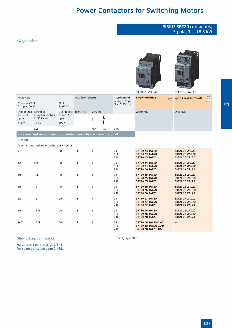
AC operation
3RT20 2 . -1A . 00 3RT20 2 . -2A . 00
Rated data Auxiliary contacts Rated control supply voltage Us at 50/60 Hz
Screw terminals Spring-type terminals
AC-2 and AC-3, Tu: Up to 60 °C
AC-1, Tu: 40 °C
Operational current Ie up to
415 V
Rating of induction motors at 50 Hz and
415 V
Operational current Ie up to
690 V
Ident. No. Version Order No. Order No.
A kW A NO NC V AC
For screw and snap-on mounting onto 35 mm standard mounting rail
Size S0
Terminal designations according to EN 50012
9 4 40 11 1 1 24110230
3RT20 23-1AC203RT20 23-1AG203RT20 23-1AL20
3RT20 23-2AC203RT20 23-2AG203RT20 23-2AL20
12 5.5 40 11 1 1 24110230
3RT20 24-1AC203RT20 24-1AG203RT20 24-1AL20
3RT20 24-2AC203RT20 24-2AG203RT20 24-2AL20
16 7.5 40 11 1 1 24110230
3RT20 25-1AC203RT20 25-1AG203RT20 25-1AL20
3RT20 25-2AC203RT20 25-2AG203RT20 25-2AL20
25 11 40 11 1 1 24110230
3RT20 26-1AC203RT20 26-1AG203RT20 26-1AL20
3RT20 26-2AC203RT20 26-2AG203RT20 26-2AL20
32 15 50 11 1 1 24110230
3RT20 27-1AC203RT20 27-1AG203RT20 27-1AL20
3RT20 27-2AC203RT20 27-2AG203RT20 27-2AL20
38 18.5 50 11 1 1 24110230
3RT20 28-1AC203RT20 28-1AG203RT20 28-1AL20
3RT20 28-2AC203RT20 28-2AG203RT20 28-2AL20
401) 18.5 50 11 1 1 24110230
3RT20 28-1AC20-0JA03RT20 28-1AG20-0JA03RT20 28-1AL20-0JA0
———
Other voltages on request.
For accessories, see page 2/151. For spare parts, see page 2/168.
1) Tu: upto 50°C
Power Contactors for Switching Motors
2/25
2
SIRIUS 3RT20 contactors,3-pole, 3 ... 18.5 kW
SIRIUS 3RT20 contactors,3-pole, 3 ... 18.5 kW
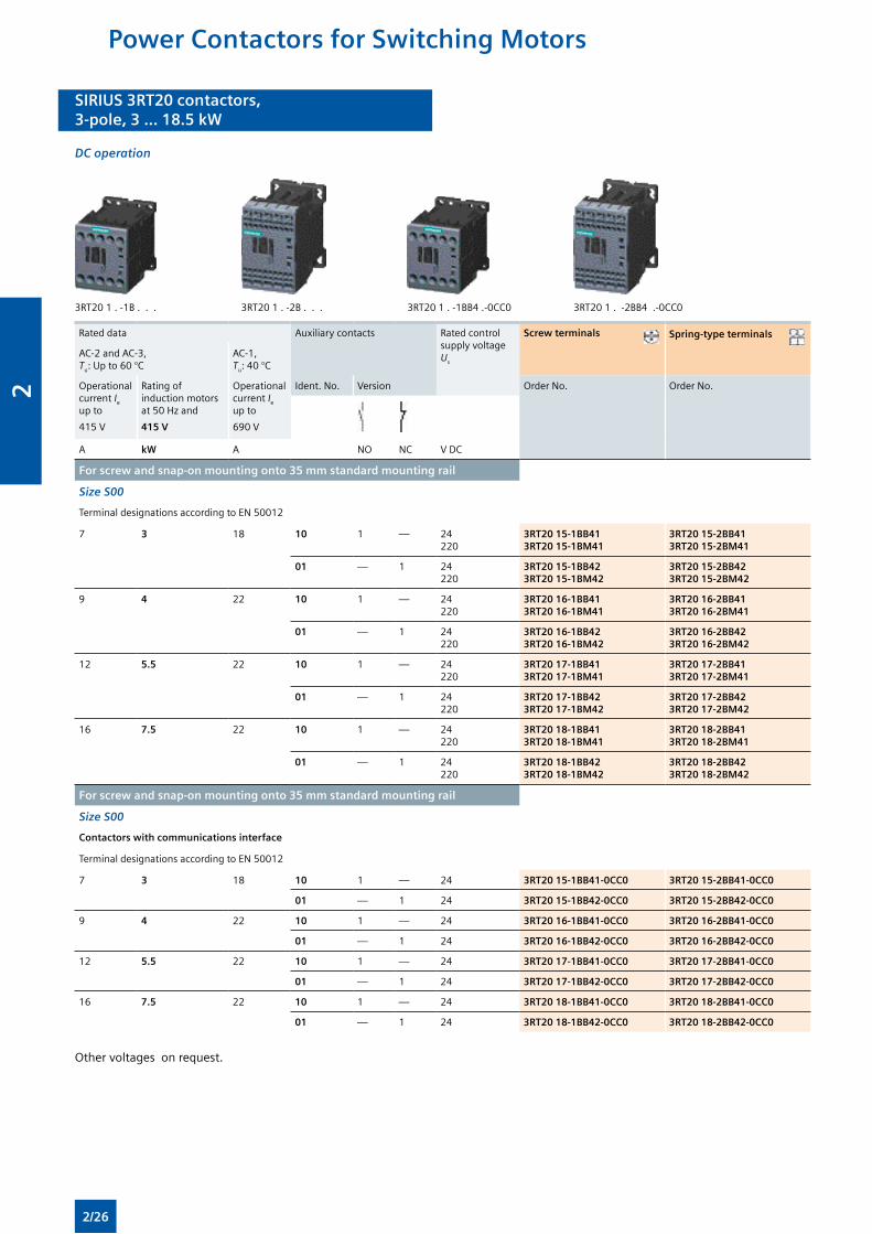
DC operation
3RT20 1 . -1B . . . 3RT20 1 . -2B . . . 3RT20 1 . -1BB4 .-0CC0 3RT20 1 . -2BB4 .-0CC0
Rated data Auxiliary contacts Rated control supply voltage Us
Screw terminals Spring-type terminals
AC-2 and AC-3, Tu: Up to 60 °C
AC-1, Tu: 40 °C
Operational current Ie up to
415 V
Rating of induction motors at 50 Hz and
415 V
Operational current Ie up to
690 V
Ident. No. Version Order No. Order No.
A kW A NO NC V DC
For screw and snap-on mounting onto 35 mm standard mounting rail
Size S00
Terminal designations according to EN 50012
7 3 18 10 1 — 24220
3RT20 15-1BB413RT20 15-1BM41
3RT20 15-2BB413RT20 15-2BM41
01 — 1 24220
3RT20 15-1BB423RT20 15-1BM42
3RT20 15-2BB423RT20 15-2BM42
9 4 22 10 1 — 24220
3RT20 16-1BB413RT20 16-1BM41
3RT20 16-2BB413RT20 16-2BM41
01 — 1 24220
3RT20 16-1BB423RT20 16-1BM42
3RT20 16-2BB423RT20 16-2BM42
12 5.5 22 10 1 — 24220
3RT20 17-1BB413RT20 17-1BM41
3RT20 17-2BB413RT20 17-2BM41
01 — 1 24220
3RT20 17-1BB423RT20 17-1BM42
3RT20 17-2BB423RT20 17-2BM42
16 7.5 22 10 1 — 24220
3RT20 18-1BB413RT20 18-1BM41
3RT20 18-2BB413RT20 18-2BM41
01 — 1 24220
3RT20 18-1BB423RT20 18-1BM42
3RT20 18-2BB423RT20 18-2BM42
For screw and snap-on mounting onto 35 mm standard mounting rail
Size S00
Contactors with communications interface
Terminal designations according to EN 50012
7 3 18 10 1 — 24 3RT20 15-1BB41-0CC0 3RT20 15-2BB41-0CC0
01 — 1 24 3RT20 15-1BB42-0CC0 3RT20 15-2BB42-0CC0
9 4 22 10 1 — 24 3RT20 16-1BB41-0CC0 3RT20 16-2BB41-0CC0
01 — 1 24 3RT20 16-1BB42-0CC0 3RT20 16-2BB42-0CC0
12 5.5 22 10 1 — 24 3RT20 17-1BB41-0CC0 3RT20 17-2BB41-0CC0
01 — 1 24 3RT20 17-1BB42-0CC0 3RT20 17-2BB42-0CC0
16 7.5 22 10 1 — 24 3RT20 18-1BB41-0CC0 3RT20 18-2BB41-0CC0
01 — 1 24 3RT20 18-1BB42-0CC0 3RT20 18-2BB42-0CC0
Other voltages on request.
Power Contactors for Switching Motors
2/26
2
SIRIUS 3RT20 contactors,3-pole, 3 ... 18.5 kW
SIRIUS 3RT20 contactors,3-pole, 3 ... 18.5 kW
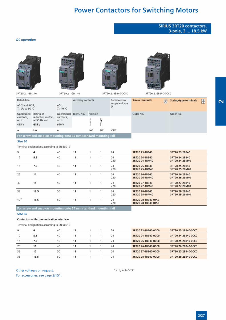
DC operation
3RT20 2 . -1B . 40 3RT20 2 . -2B . 40 3RT20 2.-1BB40-0CC0 3RT20 2.-2BB40-0CC0
Rated data Auxiliary contacts Rated control supply voltage Us
Screw terminals Spring-type terminals
AC-2 and AC-3, Tu: Up to 60 °C
AC-1, Tu: 40 °C
Operational current Ie up to
415 V
Rating of induction motors at 50 Hz and
415 V
Operational current Ie up to
690 V
Ident. No. Version Order No. Order No.
A kW A NO NC V DC
For screw and snap-on mounting onto 35 mm standard mounting rail
Size S0
Terminal designations according to EN 50012
9 4 40 11 1 1 24 3RT20 23-1BB40 3RT20 23-2BB40
12 5.5 40 11 1 1 24220
3RT20 24-1BB403RT20 24-1BM40
3RT20 24-2BB403RT20 24-2BM40
16 7.5 40 11 1 1 24220
3RT20 25-1BB403RT20 25-1BM40
3RT20 25-2BB403RT20 25-2BM40
25 11 40 11 1 1 24220
3RT20 26-1BB403RT20 26-1BM40
3RT20 26-2BB403RT20 26-2BM40
32 15 50 11 1 1 24220
3RT20 27-1BB403RT20 27-1BM40
3RT20 27-2BB403RT20 27-2BM40
38 18.5 50 11 1 1 24220
3RT20 28-1BB403RT20 28-1BM40
3RT20 28-2BB403RT20 28-2BM40
401) 18.5 50 11 1 1 24220
3RT20 28-1BB40-0JA03RT20 28-1BB40-0JA0
——
For screw and snap-on mounting onto 35 mm standard mounting rail
Size S0
Contactors with communication interface
Terminal designations according to EN 50012
9 4 40 11 1 1 24 3RT20 23-1BB40-0CC0 3RT20 23-2BB40-0CC0
12 5.5 40 11 1 1 24 3RT20 24-1BB40-0CC0 3RT20 24-2BB40-0CC0
16 7.5 40 11 1 1 24 3RT20 25-1BB40-0CC0 3RT20 25-2BB40-0CC0
25 11 40 11 1 1 24 3RT20 26-1BB40-0CC0 3RT20 26-2BB40-0CC0
32 15 50 11 1 1 24 3RT20 27-1BB40-0CC0 3RT20 27-2BB40-0CC0
38 18.5 50 11 1 1 24 3RT20 28-1BB40-0CC0 3RT20 28-2BB40-0CC0
Other voltages on request.
For accessories, see page 2/151.
1) Tu: upto 50°C
Power Contactors for Switching Motors
2/27
2
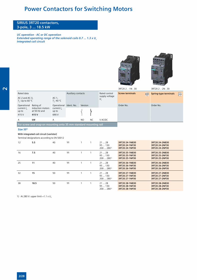
SIRIUS 3RT20 contactors,3-pole, 3 ... 18.5 kW
SIRIUS 3RT20 contactors,3-pole, 3 ... 18.5 kW
UC operation · AC or DC operation Extended operating range of the solenoid coils 0.7 ... 1.3 x Us Integrated coil circuit
3RT20 2 . -1N . 30 3RT20 2 . -2N . 30
Rated data Auxiliary contacts Rated control supply voltage Us
Screw terminals Spring-type terminals
AC-2 and AC-3, Tu: Up to 60 °C
AC-1, Tu: 40 °C
Operational current Ie up to
415 V
Rating of induction motors at 50 Hz and
415 V
Operational current Ie up to
690 V
Ident. No. Version Order No. Order No.
A kW A NO NC V AC/DC
For screw and snap-on mounting onto 35 mm standard mounting rail
Size S01)
With integrated coil circuit (varistor)
Terminal designations according to EN 50012
12 5.5 40 11 1 1 21 ... 2895 ... 130200 ... 2801)
3RT20 24-1NB303RT20 24-1NF303RT20 24-1NP30
3RT20 24-2NB303RT20 24-2NF303RT20 24-2NP30
16 7.5 40 11 1 1 21 ... 2895 ... 130200 ... 2801)
3RT20 25-1NB303RT20 25-1NF303RT20 25-1NP30
3RT20 25-2NB303RT20 25-2NF303RT20 25-2NP30
25 11 40 11 1 1 21 ... 2895 ... 130200 ... 2801)
3RT20 26-1NB303RT20 26-1NF303RT20 26-1NP30
3RT20 26-2NB303RT20 26-2NF303RT20 26-2NP30
32 15 50 11 1 1 21 ... 2895 ... 130200 ... 2801)
3RT20 27-1NB303RT20 27-1NF303RT20 27-1NP30
3RT20 27-2NB303RT20 27-2NF303RT20 27-2NP30
38 18.5 50 11 1 1 21 ... 2895 ... 130200 ... 2801)
3RT20 28-1NB303RT20 28-1NF303RT20 28-1NP30
3RT20 28-2NB303RT20 28-2NF303RT20 28-2NP30
1) At 280 V: upper limit =1.1 x Us.
Power Contactors for Switching Motors
2/28
2
SIRIUS 3RT20 contactors,3-pole, 3 ... 18.5 kW
SIRIUS 3RT20 contactors,3-pole, 3 ... 18.5 kW
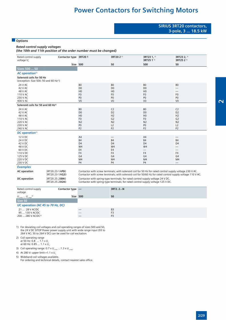
Options
Rated control supply voltages (the 10th and 11th position of the order number must be changed)
Rated control supply voltage Us
Contactor type
Size
3RT20 1
S00
3RT20 2 5)
S0
3RT23 1, 5) 3RT25 1 5)
S00
3RT23 2, 5) 3RT25 2 5)
S0
Sizes S00 ... S0
AC operation1)
Solenoid coils for 50 Hz (exception: Size S00: 50 and 60 Hz2))
24 V AC 42 V AC 48 V AC110 V AC230 V AC400 V AC
B0D0H0F0P0V0
B0D0H0F0P0V0
B0D0H0F0P0V0
B0——F0P0V0
Solenoid coils for 50 and 60 Hz2)
24 V AC 42 V AC 48 V AC110 V AC220 V AC230 V AC240 V AC
B0D0H0F0N2P0P2
C2D2H2G2N2L2P2
B0D0H0F0N2P0P2
C2D2H2G2N2L2P2
DC operation1)
12 V DC 24 V DC 42 V DC 48 V DC 60 V DC110 V DC125 V DC220 V DC230 V DC
A4B4D4W4E4F4G4M4P4
—B4D4W4E4F4G4M4P4
A4B4D4W4—F4G4M4P4
—B4D4——F4G4M4—
ExamplesAC operation 3RT20 23-1AP00
3RT20 23-1AG20Contactor with screw terminals; with solenoid coil for 50 Hz for rated control supply voltage 230 V AC.Contactor with screw terminals; with solenoid coil for 50/60 Hz for rated control supply voltage 110 V AC.
DC operation 3RT20 25-2BB403RT20 25-2BG40
Contactor with spring-type terminals; for rated control supply voltage 24 V DC.Contactor with spring-type terminals; for rated control supply voltage 125 V DC.
Rated control supply voltage
Contactor type — 3RT2. 2.-.N
Us min ... Us max3) Size S00 S0
Size S0
UC operation (AC 45 to 70 Hz, DC) 21 ... 28 V AC/DC 95 ... 130 V AC/DC200 ... 280 V AC/DC4)
———
B3F3P3
1) For deviating coil voltages and coil operating ranges of sizes S00 and S0, the 24 V DC SITOP Power power supply unit with wide range input (93 to 264 V AC; 30 to 264 V DC) can be used for coil excitation.
2) Coil operating range at 50 Hz: 0.8 ... 1.1 x Us at 60 Hz: 0.85 ... 1.1 x Us.
3) Coil operating range: 0.7 x Us min ...1.3 x Us max.
4) At 280 V: upper limit =1.1 x Us.
5) Wideband coil voltages available. For ordering and technical details, contact nearest sales office.
Power Contactors for Switching Motors
2/29
2
SIRIUS 3RT10 contactors,3-pole, 15 ... 250 kW
SIRIUS 3RT10 contactors,3-pole, 15 ... 250 kW
Overview
Standards
IEC 60947-1, EN 60947-1, IEC 60947-4-1, EN 60947-4-1, IEC 60947-5-1, EN 60947-5-1 (auxiliary switches)
The 3RT1 contactors are climate-proof. They are finger-safe according to EN 50274.
Contact reliability
If voltages ≤ 110 V and currents ≤ 100 mA are to be switched, the auxiliary contacts of the 3RT1 contactor or 3RH11 contactor relay should be used as they guarantee a high level of contact reliability.
These auxiliary contacts are particularly suitable for solid-state circuits with currents ≥ 1 mA at a voltage ≥ 17 V.
Short-circuit protection of the contactors
For more information about short-circuit protection of contactors without overload relay, see “Technical specifications”. For short-circuit protection of the contactors with overload relay see “Overload Relays”.
To assemble fuseless motor feeders you must select combinations of motor starter protector and contactor as explained in “Fuseless Load Feeders”.
Motor protection
3RU11 thermal overload relays or 3RB20/3RB21 solid-state overload relays can be fitted to the 3RT1 contactors for protection against overload. The overload relays must be ordered separately.
Ratings of induction motors
The quoted rating (in kW) refers to the output power on the motor shaft (according to the nameplate).
Surge suppression
3RT1 contactors can be retrofitted with RC elements, varistors, diodes or diode assemblies (assembly of diode and Zener diode for short break times) for damping opening surges in the coil.
Note:
The OFF-delay of the NO contact and the ON-delay of the NC contact are increased if the contactor coils are attenuated against voltage peaks (noise suppression diode 6 to 10 times; diode assembly 2 to 6 times, varistor +2 to 5 ms).
Sizes S00 and S0, up to 11 kW
The 3RT1 devices in these sizes can be found in SIRIUS datasheet 2009.
Sizes S2 and S3, up to 45 kW
Auxiliary contact complement
The basic units of sizes S2 and S3 are delivered only with the main contacts and can be extended with auxiliary switch blocks.
Surge suppression
For size S2 and S3 contactors, varistors and RC elements can be snapped on either on the top or directly below the coil terminals. Diode assemblies are available in 2 different versions on account of their polarity. Depending on the application they can be connected either only at the bottom (assembly with motor starter protector) or only at the top (assembly with overload relay).
The plug-in direction of the diodes and diode assemblies is specified by coding.
Exceptions: 3RT19 26-1T . 00 and 3RT19 36-1T . 00, in this case the plug-in direction is marked with “+” and “-”.
Sizes S6 to S12, > 45 to 250 kW
• 3RT10, contactors for switching motors,
• 3RT12, vacuum contactors for switching motors,
• 3RT14, contactors for AC-1 applications.
Operating mechanism types
Two types of solenoid operation are available:
• Conventional operating mechanism
• Solid-state operating mechanism (with 3 performance levels)
Control supply voltage
The contactors have a UC operating mechanism which can be operated with AC (40 to 60 Hz) as well as with DC.
Withdrawable coils
For simple coil replacement, e. g. if the application is replaced, the solenoid coil can be pulled out upwards after the release mechanism has been actuated and can be replaced by any other coil of the same size.
Auxiliary contact complement
Contactor sizes S6 to S12 are supplied with mounted auxiliary switch blocks.
• 3RT10 and 3RT14 contactors: Auxiliary contacts mounted laterally and on front
• 3RT12 vacuum contactors: Auxiliary contacts mounted laterally
Contactors with conventional operating mechanism
Version 3RT1 . . . - . A:
The solenoid coil is switched directly on and off with the control supply voltage Us by way of terminals A1/A2.
Multi-voltage range for the control supply voltage Us:
Only one coil covers several close-lying control supply voltages which are used worldwide, e. g. 110–115–120–127 V AC/DC or 220–230–240 V AC/DC. Allowance is made in addition for am operating range of 0.8 times the lower (Us min) and 1.1 times the upper (Us max) rated control supply voltage within which the contactor switches reliably and no thermal overload occurs.
Contactors with solid-state operating mechanism
The solenoid coil is supplied selectively with the power required for reliable switching and holding by upstream control electronics.
• Wide voltage range for the control supply voltage Us: Compared with the conventional operating mechanism, the solid-state operating mechanism covers an even broader range of control supply voltages used worldwide within one coil variant. For example, the coil for 200 to 277 V AC/DC (Us min to Us max) covers the voltages 200-208-220-230-240-254-277 V used worldwide.
• Extended operating range 0.7 to 1.25 x Us: The wide range for the rated control supply voltage and the additionally allowed coil operating range of 0.8 x Us min to 1.1 x Us max results in an extended coil operating range of at least 0.7 to 1.25 x Us, within which the contactors will operate reliably, for the most common control supply voltages of 24, 110 and 230 V.
Power Contactors for Switching Motors
2/30
2
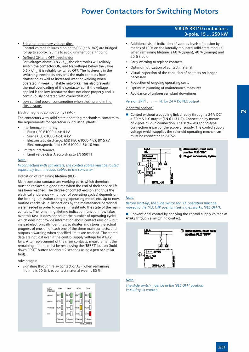
SIRIUS 3RT10 contactors,3-pole, 15 ... 250 kW
SIRIUS 3RT10 contactors,3-pole, 15 ... 250 kW
• Bridging temporary voltage dips: Control voltage failures dipping to 0 V (at A1/A2) are bridged for up to approx. 25 ms to avoid unintentional tripping.
• Defined ON and OFF thresholds: For voltages above 0.8 x Us min the electronics will reliably switch the contactor ON, and for voltages below the value 0.5 x Us min it is reliably switched OFF. The hysteresis in the switching thresholds prevents the main contacts from chattering as well as increased wear or welding when operated in weak, unstable networks. This also prevents thermal overloading of the contactor coil if the voltage applied is too low (contactor does not close properly and is continuously operated with overexcitation).
• Low control power consumption when closing and in the closed state.
Electromagnetic compatibility (EMC)
The contactors with solid-state operating mechanism conform to the requirements for operation in industrial plants:
• Interference immunity - Burst (IEC 61000-4-4): 4 kV - Surge (IEC 61000-4-5): 4 kV - Electrostatic discharge, ESD (IEC 61000-4-2): 8/15 kV - Electromagnetic field (IEC 61000-4-3): 10 V/m
• Emitted interference - Limit value class A according to EN 55011
Note:
In connection with converters, the control cables must be routed separately from the load cables to the converter.
Indication of remaining lifetime (RLT)
Main contactor contacts are working parts which therefore must be replaced in good time when the end of their service life has been reached. The degree of contact erosion and thus the electrical endurance (= number of operating cycles) depends on the loading, utilization category, operating mode, etc. Up to now, routine checks/visual inspections by the maintenance personnel were needed in order to gain an insight into the state of the main contacts. The remaining lifetime indication function now takes over this task. It does not count the number of operating cycles – which does not provide information about contact erosion – but instead electronically identifies, evaluates and stores the actual progress of erosion of each one of the three main contacts, and outputs a warning when specified limits are reached. The stored data are not lost even if the control supply voltage for A1/A2 fails. After replacement of the main contacts, measurement the remaining lifetime must be reset using the “RESET” button (hold down RESET button for about 2 seconds using a pen or similar tool).
Advantages:
• Signaling through relay contact or AS-i when remaining lifetime is 20 %, i. e. contact material wear is 80 %.
• Additional visual indication of various levels of erosion by means of LEDs on the laterally mounted solid-state module when remaining lifetime is 60 % (green), 40 % (orange) and 20 % (red).
• Early warning to replace contacts
• Optimum utilization of contact material
• Visual inspection of the condition of contacts no longer necessary
• Reduction of ongoing operating costs
• Optimum planning of maintenance measures
• Avoidance of unforeseen plant downtimes
Version 3RT1 . . . - . N: for 24 V DC PLC output
2 control options:
n Control without a coupling link directly through a 24 V DC/ ≥ 30 mA PLC output (EN 61131-2). Connection by means of 2-pole plug-in connection. The screwless spring-type connection is part of the scope of supply. The control supply voltage which supplies the solenoid operating mechanism must be connected to A1/A2.
Note:
Before start-up, the slide switch for PLC operation must be moved to the “PLC ON” position (setting ex works: “PLC OFF”).
n Conventional control by applying the control supply voltage at A1/A2 through a switching contact.
Note:
The slide switch must be in the “PLC OFF” position (= setting ex works).
Power Contactors for Switching Motors
2/31
2
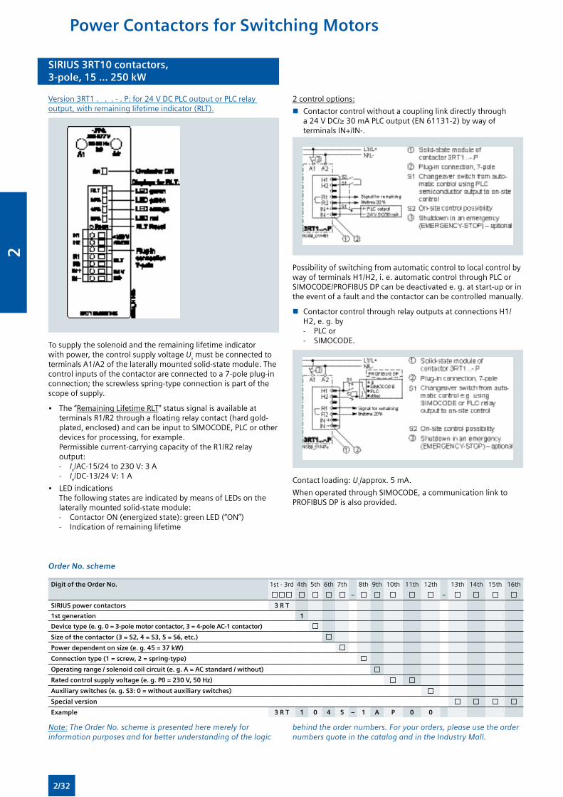
SIRIUS 3RT10 contactors,3-pole, 15 ... 250 kW
SIRIUS 3RT10 contactors,3-pole, 15 ... 250 kW
Version 3RT1 . . . - . P: for 24 V DC PLC output or PLC relay output, with remaining lifetime indicator (RLT).
To supply the solenoid and the remaining lifetime indicator with power, the control supply voltage Us must be connected to terminals A1/A2 of the laterally mounted solid-state module. The control inputs of the contactor are connected to a 7-pole plug-in connection; the screwless spring-type connection is part of the scope of supply.
• The “Remaining Lifetime RLT” status signal is available at terminals R1/R2 through a floating relay contact (hard gold-plated, enclosed) and can be input to SIMOCODE, PLC or other devices for processing, for example. Permissible current-carrying capacity of the R1/R2 relay output: - Ie/AC-15/24 to 230 V: 3 A - Ie/DC-13/24 V: 1 A
• LED indications The following states are indicated by means of LEDs on the laterally mounted solid-state module: - Contactor ON (energized state): green LED (“ON”) - Indication of remaining lifetime
2 control options:
n Contactor control without a coupling link directly through a 24 V DC/≥ 30 mA PLC output (EN 61131-2) by way of terminals IN+/IN-.
Possibility of switching from automatic control to local control by way of terminals H1/H2, i. e. automatic control through PLC or SIMOCODE/PROFIBUS DP can be deactivated e. g. at start-up or in the event of a fault and the contactor can be controlled manually.
n Contactor control through relay outputs at connections H1/H2, e. g. by - PLC or - SIMOCODE.
Contact loading: Us/approx. 5 mA.
When operated through SIMOCODE, a communication link to PROFIBUS DP is also provided.
Order No. scheme
Digit of the Order No. 1st - 3rd 4th 5th 6th 7th 8th 9th 10th 11th 12th 13th 14th 15th 16th
– –
SIRIUS power contactors 3 R T
1st generation 1
Device type (e. g. 0 = 3-pole motor contactor, 3 = 4-pole AC-1 contactor)
Size of the contactor (3 = S2, 4 = S3, 5 = S6, etc.)
Power dependent on size (e. g. 45 = 37 kW)
Connection type (1 = screw, 2 = spring-type)
Operating range / solenoid coil circuit (e. g. A = AC standard / without)
Rated control supply voltage (e. g. P0 = 230 V, 50 Hz)
Auxiliary switches (e. g. S3: 0 = without auxiliary switches)
Special version
Example 3 R T 1 0 4 5 – 1 A P 0 0
Note: The Order No. scheme is presented here merely for information purposes and for better understanding of the logic
behind the order numbers. For your orders, please use the order numbers quote in the catalog and in the Industry Mall.
Power Contactors for Switching Motors
2/32
2
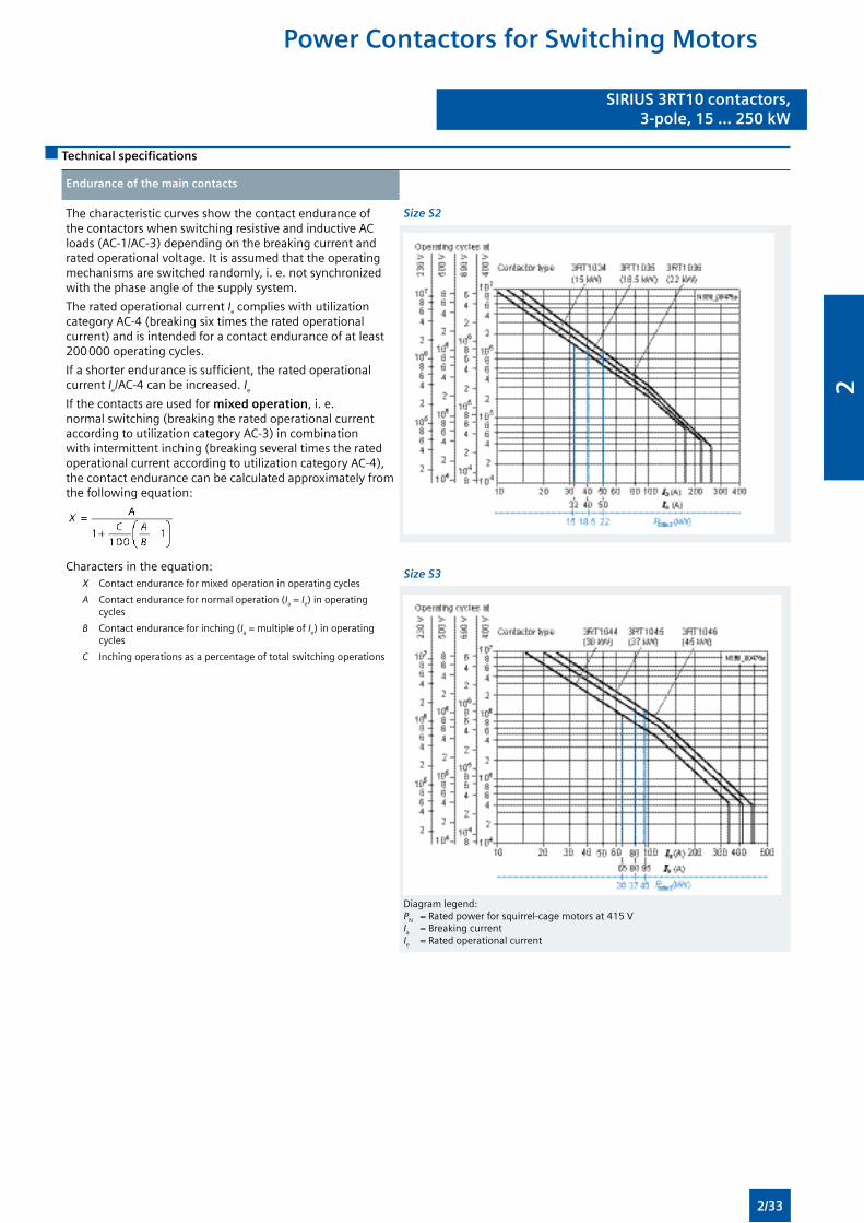
SIRIUS 3RT10 contactors,3-pole, 15 ... 250 kW
SIRIUS 3RT10 contactors,3-pole, 15 ... 250 kW
Technical specifications
Endurance of the main contacts
The characteristic curves show the contact endurance of the contactors when switching resistive and inductive AC loads (AC-1/AC-3) depending on the breaking current and rated operational voltage. It is assumed that the operating mechanisms are switched randomly, i. e. not synchronized with the phase angle of the supply system.
The rated operational current Ie complies with utilization category AC-4 (breaking six times the rated operational current) and is intended for a contact endurance of at least 200 000 operating cycles.
If a shorter endurance is sufficient, the rated operational current Ie/AC-4 can be increased. Ie
If the contacts are used for mixed operation, i. e. normal switching (breaking the rated operational current according to utilization category AC-3) in combination with intermittent inching (breaking several times the rated operational current according to utilization category AC-4), the contact endurance can be calculated approximately from the following equation:
Characters in the equation:X Contact endurance for mixed operation in operating cycles
A Contact endurance for normal operation (Ia = Ie) in operating cycles
B Contact endurance for inching (Ia = multiple of Ie) in operating cycles
C Inching operations as a percentage of total switching operations
Size S2
Size S3
Diagram legend:PN = Rated power for squirrel-cage motors at 415 VIa = Breaking currentIe = Rated operational current
Power Contactors for Switching Motors
2/33
2
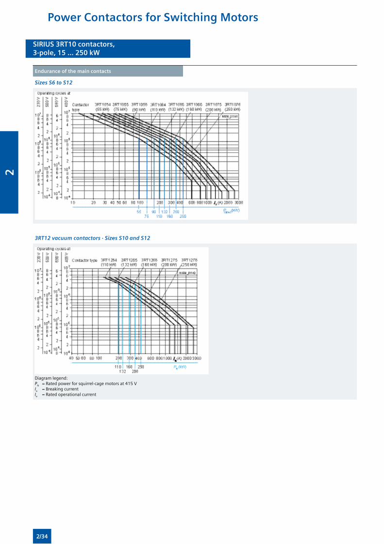
SIRIUS 3RT10 contactors,3-pole, 15 ... 250 kW
SIRIUS 3RT10 contactors,3-pole, 15 ... 250 kW
Endurance of the main contacts
Sizes S6 to S12
3RT12 vacuum contactors · Sizes S10 and S12
Diagram legend:PN = Rated power for squirrel-cage motors at 415 VIa = Breaking currentIe = Rated operational current
Power Contactors for Switching Motors
2/34
2
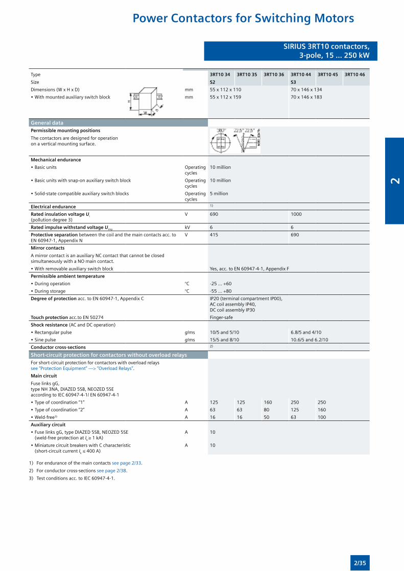
SIRIUS 3RT10 contactors,3-pole, 15 ... 250 kW
SIRIUS 3RT10 contactors,3-pole, 15 ... 250 kW
Type
Size
3RT10 34
S2
3RT10 35 3RT10 36 3RT10 44
S3
3RT10 45 3RT10 46
Dimensions (W x H x D) mm 55 x 112 x 110 70 x 146 x 134
• With mounted auxiliary switch block mm 55 x 112 x 159 70 x 146 x 183
General dataPermissible mounting positions
The contactors are designed for operation on a vertical mounting surface.
Mechanical endurance
• Basic units Operating cycles
10 million
• Basic units with snap-on auxiliary switch block Operating cycles
10 million
• Solid-state compatible auxiliary switch blocks Operating cycles
5 million
Electrical endurance 1)
Rated insulation voltage Ui (pollution degree 3)
V 690 1000
Rated impulse withstand voltage Uimp kV 6 6
Protective separation between the coil and the main contacts acc. to EN 60947-1, Appendix N
V 415 690
Mirror contacts
A mirror contact is an auxiliary NC contact that cannot be closed simultaneously with a NO main contact.
• With removable auxiliary switch block Yes, acc. to EN 60947-4-1, Appendix F
Permissible ambient temperature
• During operation °C -25 ... +60
• During storage °C -55 ... +80
Degree of protection acc. to EN 60947-1, Appendix C IP20 (terminal compartment IP00), AC coil assembly IP40, DC coil assembly IP30
Touch protection acc.to EN 50274 Finger-safe
Shock resistance (AC and DC operation)
• Rectangular pulse g/ms 10/5 and 5/10 6.8/5 and 4/10
• Sine pulse g/ms 15/5 and 8/10 10.6/5 and 6.2/10
Conductor cross-sections 2)
Short-circuit protection for contactors without overload relaysFor short-circuit protection for contactors with overload relays see “Protection Equipment” —> “Overload Relays”.
Main circuit
Fuse links gG, type NH 3NA, DIAZED 5SB, NEOZED 5SE according to IEC 60947-4-1/ EN 60947-4-1
• Type of coordination “1” A 125 125 160 250 250
• Type of coordination “2” A 63 63 80 125 160
• Weld-free3) A 16 16 50 63 100
Auxiliary circuit
• Fuse links gG, type DIAZED 5SB, NEOZED 5SE (weld-free protection at Ik ≥ 1 kA)
A 10
• Miniature circuit breakers with C characteristic (short-circuit current Ik ≤ 400 A)
A 10
1) For endurance of the main contacts see page 2/33.
2) For conductor cross-sections see page 2/38.
3) Test conditions acc. to IEC 60947-4-1.
Power Contactors for Switching Motors
2/35
2
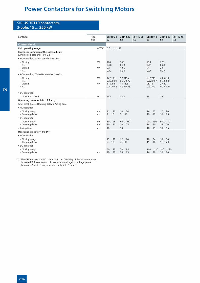
SIRIUS 3RT10 contactors,3-pole, 15 ... 250 kW
SIRIUS 3RT10 contactors,3-pole, 15 ... 250 kW
Contactor TypeSize
3RT10 34S2
3RT10 35S2
3RT10 36S2
3RT10 44S3
3RT10 45S3
3RT10 46S3
Control circuitCoil operating range AC/DC 0.8 ... 1.1 x Us
Power consumption of the solenoid coils (when coil is cold and 1.0 x Us)
• AC operation, 50 Hz, standard version
- Closing - P.f. - Closed - P.f.
VA VA
1040.789.70.42
1450.7912.50.36
2180.61210.26
2700.68220.27
• AC operation, 50/60 Hz, standard version
- Closing - P.f. - Closed - P.f.
VA VA
127/1130.73/0.6911.3/9.50.41/0.42
170/1550.76/0.7215/11.80.35/0.38
247/2110.62/0.5725/180.27/0.3
298/2740.7/0.6227/200.29/0.31
• DC operation
- Closing = Closed W 13.3 13.3 15 15
Operating times for 0.8 ... 1.1 x Us1)
Total break time = Opening delay + Arcing time
• AC operation
- Closing delay - Opening delay
msms
11 ... 307 ... 10
10 ... 247 ... 10
16 ... 5710 ... 19
17 ... 9010 ... 25
• DC operation
- Closing delay - Opening delay
msms
50 ... 9520 ... 30
60 ... 10020 ... 25
90 ... 23014 ... 20
90 ... 23014 ... 20
• Arcing time ms 10 10 10 ... 15 10 ... 15
Operating times for 1.0 x Us1)
• AC operation
- Closing delay - Opening delay
13 ... 227 ... 10
12 ... 207 ... 10
18 ... 3411 ... 18
18 ... 3011 ... 23
• DC operation
- Closing delay - Opening delay
ms
60 ... 7520 ... 30
70 ... 8520 ... 25
100 ... 12016 ... 20
100 ... 12016 ... 20
1) The OFF-delay of the NO contact and the ON-delay of the NC contact are increased if the contactor coils are attenuated against voltage peaks (varistor +2 ms to 5 ms, diode assembly: 2 to 6 times).
Power Contactors for Switching Motors
2/36
2
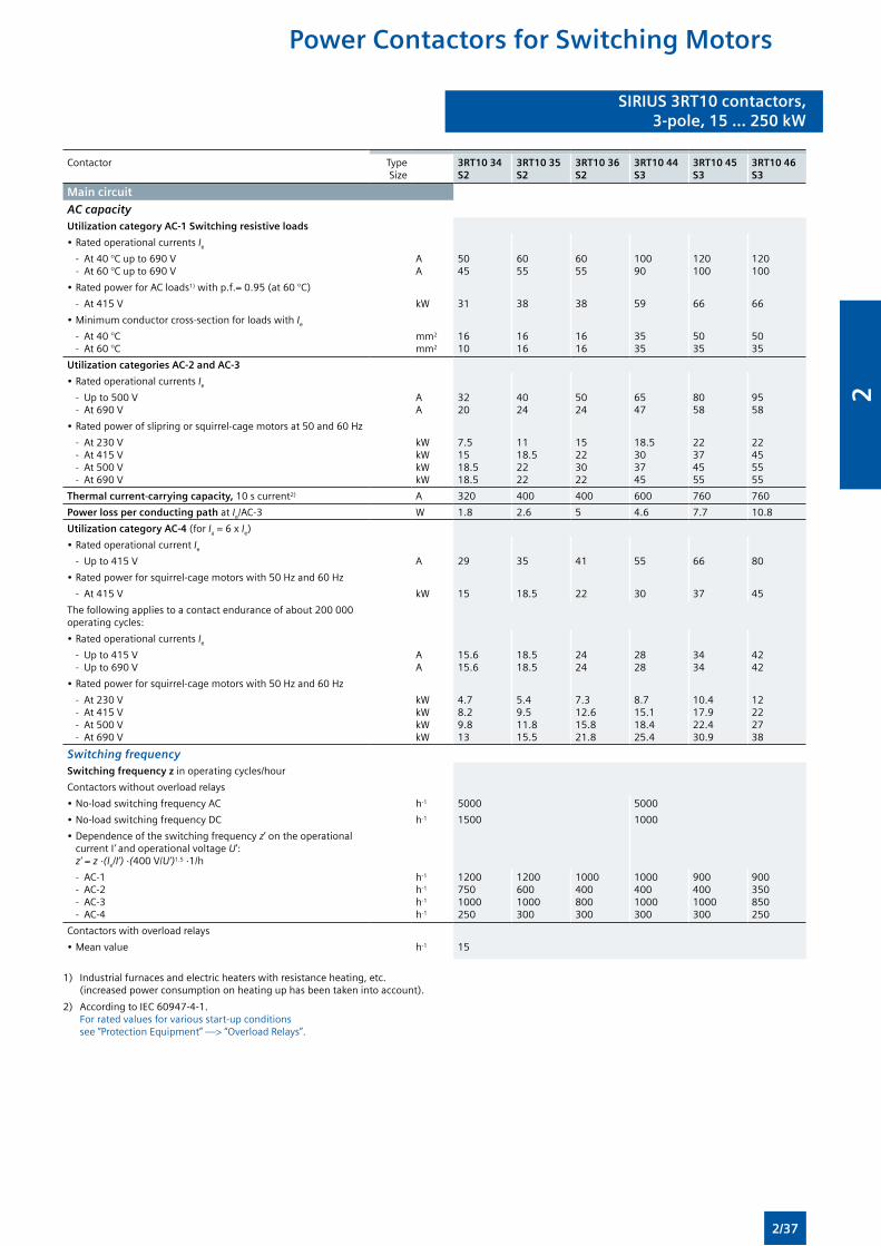
SIRIUS 3RT10 contactors,3-pole, 15 ... 250 kW
SIRIUS 3RT10 contactors,3-pole, 15 ... 250 kW
Contactor TypeSize
3RT10 34S2
3RT10 35S2
3RT10 36S2
3RT10 44S3
3RT10 45S3
3RT10 46S3
Main circuit
AC capacityUtilization category AC-1 Switching resistive loads
• Rated operational currents Ie
- At 40 °C up to 690 V - At 60 °C up to 690 V
AA
5045
6055
6055
10090
120100
120100
• Rated power for AC loads1) with p.f.= 0.95 (at 60 °C)
- At 415 V kW 31 38 38 59 66 66
• Minimum conductor cross-section for loads with Ie
- At 40 °C - At 60 °C
mm2
mm2
1610
1616
1616
3535
5035
5035
Utilization categories AC-2 and AC-3
• Rated operational currents Ie
- Up to 500 V - At 690 V
AA
3220
4024
5024
6547
8058
9558
• Rated power of slipring or squirrel-cage motors at 50 and 60 Hz
- At 230 V - At 415 V - At 500 V - At 690 V
kWkWkWkW
7.51518.518.5
1118.52222
15223022
18.5303745
22374555
22455555
Thermal current-carrying capacity, 10 s current2) A 320 400 400 600 760 760
Power loss per conducting path at Ie/AC-3 W 1.8 2.6 5 4.6 7.7 10.8
Utilization category AC-4 (for Ia = 6 x Ie)
• Rated operational current Ie
- Up to 415 V A 29 35 41 55 66 80
• Rated power for squirrel-cage motors with 50 Hz and 60 Hz
- At 415 V kW 15 18.5 22 30 37 45
The following applies to a contact endurance of about 200 000 operating cycles:
• Rated operational currents Ie
- Up to 415 V - Up to 690 V
AA
15.615.6
18.518.5
2424
2828
3434
4242
• Rated power for squirrel-cage motors with 50 Hz and 60 Hz
- At 230 V - At 415 V - At 500 V - At 690 V
kWkWkWkW
4.78.29.813
5.49.511.815.5
7.312.615.821.8
8.715.118.425.4
10.417.922.430.9
12222738
Switching frequencySwitching frequency z in operating cycles/hour
Contactors without overload relays
• No-load switching frequency AC h-1 5000 5000
• No-load switching frequency DC h-1 1500 1000
• Dependence of the switching frequency z’ on the operational current I’ and operational voltage U’: z’ = z ·(Ie/I’) ·(400 V/U’)1.5 ·1/h
- AC-1 - AC-2 - AC-3 - AC-4
h-1
h-1
h-1
h-1
12007501000250
12006001000300
1000400800300
10004001000300
9004001000300
900350850250
Contactors with overload relays
• Mean value h-1 15
1) Industrial furnaces and electric heaters with resistance heating, etc. (increased power consumption on heating up has been taken into account).
2) According to IEC 60947-4-1. For rated values for various start-up conditions see “Protection Equipment” —> “Overload Relays”.
Power Contactors for Switching Motors
2/37
2
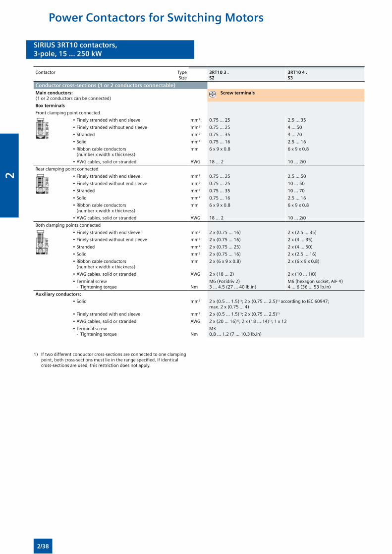
SIRIUS 3RT10 contactors,3-pole, 15 ... 250 kW
SIRIUS 3RT10 contactors,3-pole, 15 ... 250 kW
Contactor TypeSize
3RT10 3 . S2
3RT10 4 . S3
Conductor cross-sections (1 or 2 conductors connectable)Main conductors:(1 or 2 conductors can be connected)
Screw terminals
Box terminals
Front clamping point connected
• Finely stranded with end sleeve mm² 0.75 ... 25 2.5 ... 35
• Finely stranded without end sleeve mm² 0.75 ... 25 4 ... 50
• Stranded mm² 0.75 ... 35 4 ... 70
• Solid mm² 0.75 ... 16 2.5 ... 16
• Ribbon cable conductors (number x width x thickness)
mm 6 x 9 x 0.8 6 x 9 x 0.8
• AWG cables, solid or stranded AWG 18 ... 2 10 ... 2/0
Rear clamping point connected
• Finely stranded with end sleeve mm² 0.75 ... 25 2.5 ... 50
• Finely stranded without end sleeve mm² 0.75 ... 25 10 ... 50
• Stranded mm² 0.75 ... 35 10 ... 70
• Solid mm² 0.75 ... 16 2.5 ... 16
• Ribbon cable conductors (number x width x thickness)
mm 6 x 9 x 0.8 6 x 9 x 0.8
• AWG cables, solid or stranded AWG 18 ... 2 10 ... 2/0
Both clamping points connected
• Finely stranded with end sleeve mm² 2 x (0.75 ... 16) 2 x (2.5 ... 35)
• Finely stranded without end sleeve mm² 2 x (0.75 ... 16) 2 x (4 ... 35)
• Stranded mm² 2 x (0.75 ... 25) 2 x (4 ... 50)
• Solid mm² 2 x (0.75 ... 16) 2 x (2.5 ... 16)
• Ribbon cable conductors (number x width x thickness)
mm 2 x (6 x 9 x 0.8) 2 x (6 x 9 x 0.8)
• AWG cables, solid or stranded AWG 2 x (18 ... 2) 2 x (10 ... 1/0)
• Terminal screw - Tightening torque
Nm
M6 (Pozidriv 2)3 ... 4.5 (27 ... 40 lb.in)
M6 (hexagon socket, A/F 4)4 ... 6 (36 ... 53 lb.in)
Auxiliary conductors:
• Solid mm² 2 x (0.5 ... 1.5)1); 2 x (0.75 ... 2.5)1) according to IEC 60947; max. 2 x (0.75 ... 4)
• Finely stranded with end sleeve mm² 2 x (0.5 ... 1.5)1); 2 x (0.75 ... 2.5)1)
• AWG cables, solid or stranded AWG 2 x (20 ... 16)1); 2 x (18 ... 14)1); 1 x 12
• Terminal screw - Tightening torque
Nm
M30.8 ... 1.2 (7 ... 10.3 lb.in)
1) If two different conductor cross-sections are connected to one clamping point, both cross-sections must lie in the range specified. If identical cross-sections are used, this restriction does not apply.
Power Contactors for Switching Motors
2/38
2
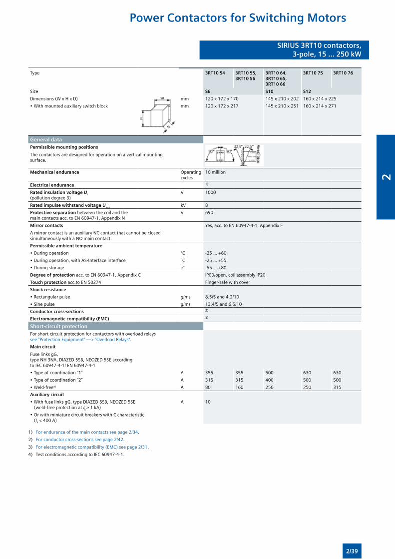
SIRIUS 3RT10 contactors,3-pole, 15 ... 250 kW
SIRIUS 3RT10 contactors,3-pole, 15 ... 250 kW
Type 3RT10 54 3RT10 55, 3RT10 56
3RT10 64, 3RT10 65, 3RT10 66
3RT10 75 3RT10 76
Size S6 S10 S12
Dimensions (W x H x D) mm 120 x 172 x 170 145 x 210 x 202 160 x 214 x 225
• With mounted auxiliary switch block mm 120 x 172 x 217 145 x 210 x 251 160 x 214 x 271
General dataPermissible mounting positions
The contactors are designed for operation on a vertical mounting surface.
Mechanical endurance Operating cycles
10 million
Electrical endurance 1)
Rated insulation voltage Ui (pollution degree 3)
V 1000
Rated impulse withstand voltage Uimp kV 8
Protective separation between the coil and the main contacts acc. to EN 60947-1, Appendix N
V 690
Mirror contacts
A mirror contact is an auxiliary NC contact that cannot be closed simultaneously with a NO main contact.
Yes, acc. to EN 60947-4-1, Appendix F
Permissible ambient temperature
• During operation °C -25 ... +60
• During operation, with AS-Interface interface °C -25 ... +55
• During storage °C -55 ... +80
Degree of protection acc. to EN 60947-1, Appendix C IP00/open, coil assembly IP20
Touch protection acc.to EN 50274 Finger-safe with cover
Shock resistance
• Rectangular pulse g/ms 8.5/5 and 4.2/10
• Sine pulse g/ms 13.4/5 and 6.5/10
Conductor cross-sections 2)
Electromagnetic compatibility (EMC) 3)
Short-circuit protectionFor short-circuit protection for contactors with overload relays see “Protection Equipment” —> “Overload Relays”.
Main circuit
Fuse links gG, type NH 3NA, DIAZED 5SB, NEOZED 5SE according to IEC 60947-4-1/ EN 60947-4-1
• Type of coordination “1” A 355 355 500 630 630
• Type of coordination “2” A 315 315 400 500 500
• Weld-free4) A 80 160 250 250 315
Auxiliary circuit
• With fuse links gG, type DIAZED 5SB, NEOZED 5SE (weld-free protection at Ik ≥ 1 kA)
A 10
• Or with miniature circuit breakers with C characteristic (Ik < 400 A)
1) For endurance of the main contacts see page 2/34.
2) For conductor cross-sections see page 2/42.
3) For electromagnetic compatibility (EMC) see page 2/31.
4) Test conditions according to IEC 60947-4-1.
Power Contactors for Switching Motors
2/39
2
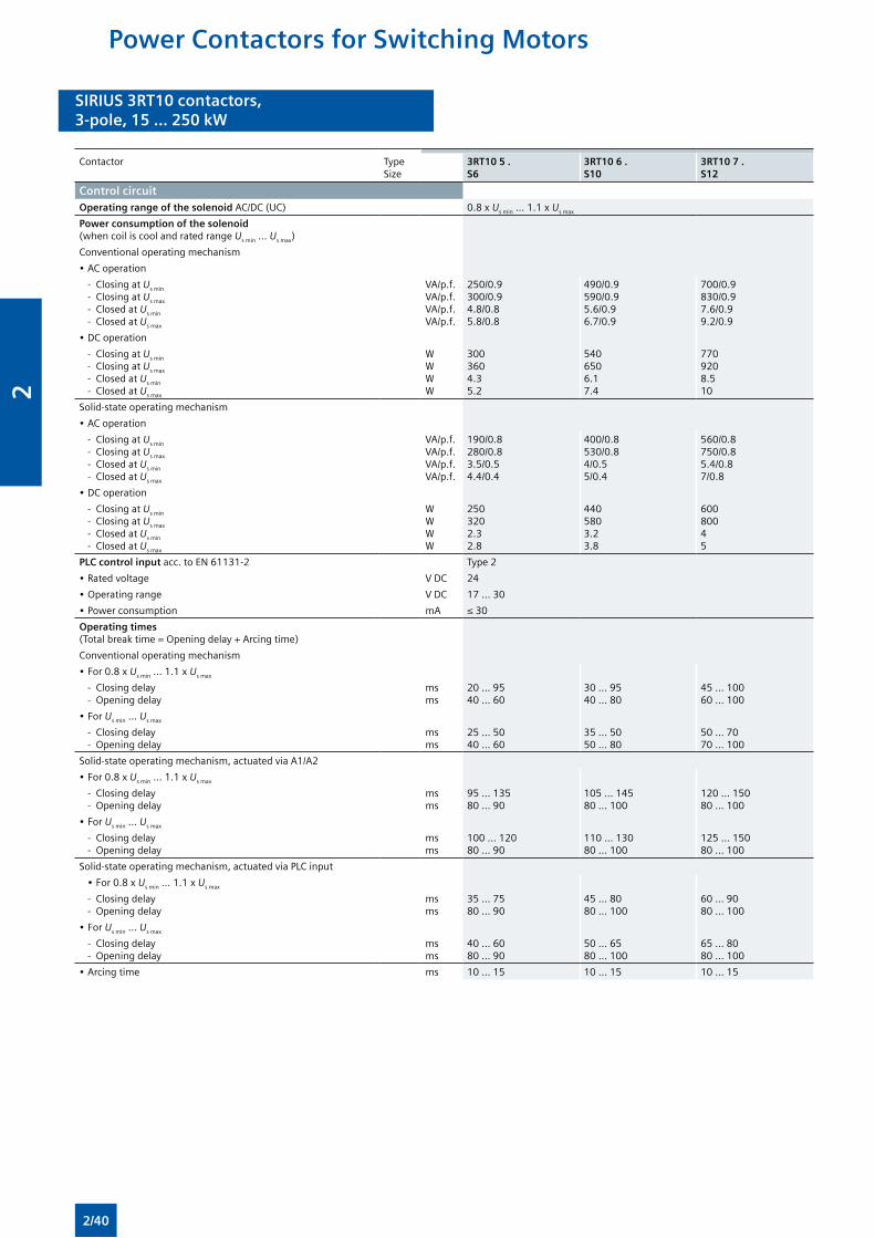
SIRIUS 3RT10 contactors,3-pole, 15 ... 250 kW
SIRIUS 3RT10 contactors,3-pole, 15 ... 250 kW
Contactor TypeSize
3RT10 5 . S6
3RT10 6 . S10
3RT10 7 . S12
Control circuitOperating range of the solenoid AC/DC (UC) 0.8 x Us min ... 1.1 x Us max
Power consumption of the solenoid (when coil is cool and rated range Us min ... Us max)
Conventional operating mechanism
• AC operation
- Closing at Us min
- Closing at Us max
- Closed at Us min
- Closed at Us max
VA/p.f.VA/p.f.VA/p.f.VA/p.f.
250/0.9300/0.94.8/0.85.8/0.8
490/0.9590/0.95.6/0.96.7/0.9
700/0.9830/0.97.6/0.99.2/0.9
• DC operation
- Closing at Us min
- Closing at Us max
- Closed at Us min
- Closed at Us max
WWWW
3003604.35.2
5406506.17.4
7709208.510
Solid-state operating mechanism
• AC operation
- Closing at Us min
- Closing at Us max
- Closed at Us min
- Closed at Us max
VA/p.f.VA/p.f.VA/p.f.VA/p.f.
190/0.8280/0.83.5/0.54.4/0.4
400/0.8530/0.84/0.55/0.4
560/0.8750/0.85.4/0.87/0.8
• DC operation
- Closing at Us min
- Closing at Us max
- Closed at Us min
- Closed at Us max
WWWW
2503202.32.8
4405803.23.8
60080045
PLC control input acc. to EN 61131-2 Type 2
• Rated voltage V DC 24
• Operating range V DC 17 ... 30
• Power consumption mA ≤ 30
Operating times (Total break time = Opening delay + Arcing time)
Conventional operating mechanism
• For 0.8 x Us min ... 1.1 x Us max
- Closing delay - Opening delay
msms
20 ... 9540 ... 60
30 ... 9540 ... 80
45 ... 10060 ... 100
• For Us min ... Us max
- Closing delay - Opening delay
msms
25 ... 5040 ... 60
35 ... 5050 ... 80
50 ... 7070 ... 100
Solid-state operating mechanism, actuated via A1/A2
• For 0.8 x Us min ... 1.1 x Us max
- Closing delay - Opening delay
msms
95 ... 13580 ... 90
105 ... 14580 ... 100
120 ... 15080 ... 100
• For Us min ... Us max
- Closing delay - Opening delay
msms
100 ... 12080 ... 90
110 ... 13080 ... 100
125 ... 15080 ... 100
Solid-state operating mechanism, actuated via PLC input
• For 0.8 x Us min ... 1.1 x Us max
- Closing delay - Opening delay
msms
35 ... 7580 ... 90
45 ... 8080 ... 100
60 ... 9080 ... 100
• For Us min ... Us max
- Closing delay - Opening delay
msms
40 ... 6080 ... 90
50 ... 6580 ... 100
65 ... 8080 ... 100
• Arcing time ms 10 ... 15 10 ... 15 10 ... 15
Power Contactors for Switching Motors
2/40
2
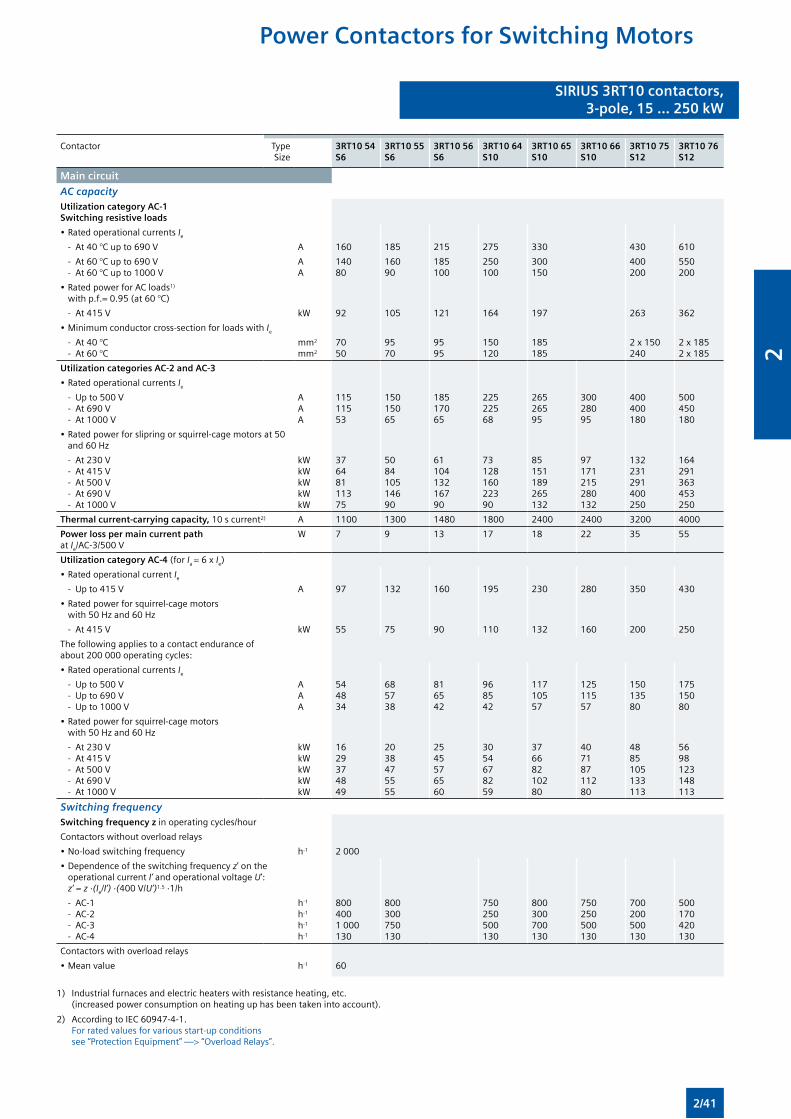
SIRIUS 3RT10 contactors,3-pole, 15 ... 250 kW
SIRIUS 3RT10 contactors,3-pole, 15 ... 250 kW
Contactor TypeSize
3RT10 54S6
3RT10 55S6
3RT10 56S6
3RT10 64S10
3RT10 65S10
3RT10 66S10
3RT10 75S12
3RT10 76S12
Main circuit
AC capacityUtilization category AC-1 Switching resistive loads
• Rated operational currents Ie
- At 40 °C up to 690 V A 160 185 215 275 330 430 610
- At 60 °C up to 690 V - At 60 °C up to 1000 V
AA
14080
16090
185100
250100
300150
400200
550200
• Rated power for AC loads1)
with p.f.= 0.95 (at 60 °C)
- At 415 V kW 92 105 121 164 197 263 362
• Minimum conductor cross-section for loads with Ie
- At 40 °C - At 60 °C
mm2
mm2
7050
9570
9595
150120
185185
2 x 150240
2 x 1852 x 185
Utilization categories AC-2 and AC-3
• Rated operational currents Ie
- Up to 500 V - At 690 V - At 1000 V
AAA
11511553
15015065
18517065
22522568
26526595
30028095
400400180
500450180
• Rated power for slipring or squirrel-cage motors at 50 and 60 Hz
- At 230 V - At 415 V - At 500 V - At 690 V - At 1000 V
kWkWkWkWkW
37648111375
508410514690
6110413216790
7312816022390
85151189265132
97171215280132
132231291400250
164291363453250
Thermal current-carrying capacity, 10 s current2) A 1100 1300 1480 1800 2400 2400 3200 4000
Power loss per main current path at Ie/AC-3/500 V
W 7 9 13 17 18 22 35 55
Utilization category AC-4 (for Ia = 6 x Ie)
• Rated operational current Ie
- Up to 415 V A 97 132 160 195 230 280 350 430
• Rated power for squirrel-cage motors with 50 Hz and 60 Hz
- At 415 V kW 55 75 90 110 132 160 200 250
The following applies to a contact endurance of about 200 000 operating cycles:
• Rated operational currents Ie
- Up to 500 V - Up to 690 V - Up to 1000 V
AAA
544834
685738
816542
968542
11710557
12511557
15013580
17515080
• Rated power for squirrel-cage motors with 50 Hz and 60 Hz
- At 230 V - At 415 V - At 500 V - At 690 V - At 1000 V
kWkWkWkWkW
1629374849
2038475555
2545576560
3054678259
37668210280
40718711280
4885105133113
5698123148113
Switching frequencySwitching frequency z in operating cycles/hour
Contactors without overload relays
• No-load switching frequency h-1 2 000
• Dependence of the switching frequency z’ on the operational current I’ and operational voltage U’: z’ = z ·(Ie/I’) ·(400 V/U’)1.5 ·1/h
- AC-1 - AC-2 - AC-3 - AC-4
h-1
h-1
h-1
h-1
8004001 000130
800300750130
750250500130
800300700130
750250500130
700200500130
500170420130
Contactors with overload relays
• Mean value h-1 60
1) Industrial furnaces and electric heaters with resistance heating, etc. (increased power consumption on heating up has been taken into account).
2) According to IEC 60947-4-1. For rated values for various start-up conditions see “Protection Equipment” —> “Overload Relays”.
Power Contactors for Switching Motors
2/41
2
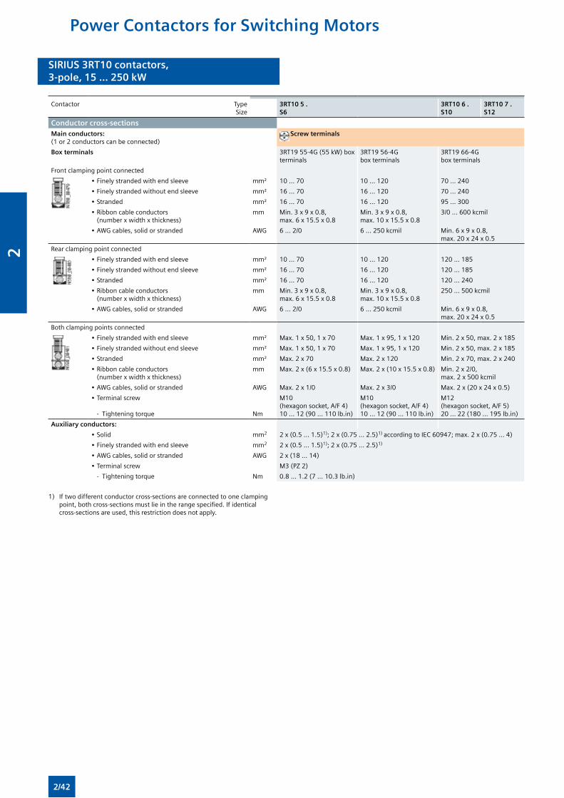
SIRIUS 3RT10 contactors,3-pole, 15 ... 250 kW
SIRIUS 3RT10 contactors,3-pole, 15 ... 250 kW
Contactor TypeSize
3RT10 5 . S6
3RT10 6 . S10
3RT10 7 . S12
Conductor cross-sectionsMain conductors:(1 or 2 conductors can be connected)
Screw terminals
Box terminals 3RT19 55-4G (55 kW) box terminals
3RT19 56-4G box terminals
3RT19 66-4G box terminals
Front clamping point connected
• Finely stranded with end sleeve mm² 10 ... 70 10 ... 120 70 ... 240
• Finely stranded without end sleeve mm² 16 ... 70 16 ... 120 70 ... 240
• Stranded mm² 16 ... 70 16 ... 120 95 ... 300
• Ribbon cable conductors (number x width x thickness)
mm Min. 3 x 9 x 0.8, max. 6 x 15.5 x 0.8
Min. 3 x 9 x 0.8, max. 10 x 15.5 x 0.8
3/0 ... 600 kcmil
• AWG cables, solid or stranded AWG 6 ... 2/0 6 ... 250 kcmil Min. 6 x 9 x 0.8, max. 20 x 24 x 0.5
Rear clamping point connected
• Finely stranded with end sleeve mm² 10 ... 70 10 ... 120 120 ... 185
• Finely stranded without end sleeve mm² 16 ... 70 16 ... 120 120 ... 185
• Stranded mm² 16 ... 70 16 ... 120 120 ... 240
• Ribbon cable conductors (number x width x thickness)
mm Min. 3 x 9 x 0.8, max. 6 x 15.5 x 0.8
Min. 3 x 9 x 0.8, max. 10 x 15.5 x 0.8
250 ... 500 kcmil
• AWG cables, solid or stranded AWG 6 ... 2/0 6 ... 250 kcmil Min. 6 x 9 x 0.8, max. 20 x 24 x 0.5
Both clamping points connected
• Finely stranded with end sleeve mm² Max. 1 x 50, 1 x 70 Max. 1 x 95, 1 x 120 Min. 2 x 50, max. 2 x 185
• Finely stranded without end sleeve mm² Max. 1 x 50, 1 x 70 Max. 1 x 95, 1 x 120 Min. 2 x 50, max. 2 x 185
• Stranded mm² Max. 2 x 70 Max. 2 x 120 Min. 2 x 70, max. 2 x 240
• Ribbon cable conductors (number x width x thickness)
mm Max. 2 x (6 x 15.5 x 0.8) Max. 2 x (10 x 15.5 x 0.8) Min. 2 x 2/0, max. 2 x 500 kcmil
• AWG cables, solid or stranded AWG Max. 2 x 1/0 Max. 2 x 3/0 Max. 2 x (20 x 24 x 0.5)
• Terminal screw
- Tightening torque
Nm
M10 (hexagon socket, A/F 4)10 ... 12 (90 ... 110 lb.in)
M10 (hexagon socket, A/F 4)10 ... 12 (90 ... 110 lb.in)
M12 (hexagon socket, A/F 5)20 ... 22 (180 ... 195 lb.in)
Auxiliary conductors:
• Solid mm2 2 x (0.5 ... 1.5)1); 2 x (0.75 ... 2.5)1) according to IEC 60947; max. 2 x (0.75 ... 4)
• Finely stranded with end sleeve mm2 2 x (0.5 ... 1.5)1); 2 x (0.75 ... 2.5)1)
• AWG cables, solid or stranded AWG 2 x (18 ... 14)
• Terminal screw M3 (PZ 2)
- Tightening torque Nm 0.8 ... 1.2 (7 ... 10.3 lb.in)
1) If two different conductor cross-sections are connected to one clamping point, both cross-sections must lie in the range specified. If identical cross-sections are used, this restriction does not apply.
Power Contactors for Switching Motors
2/42
2
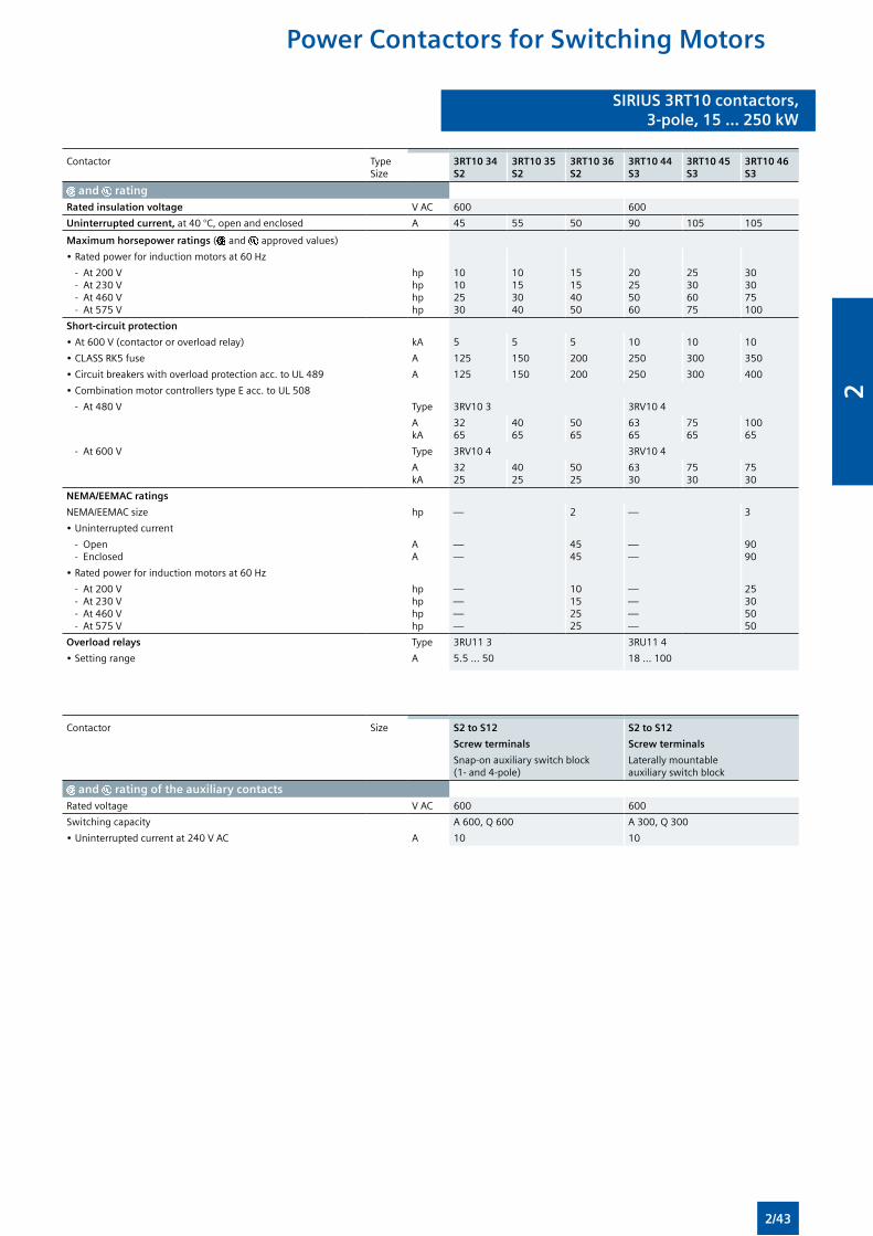
SIRIUS 3RT10 contactors,3-pole, 15 ... 250 kW
SIRIUS 3RT10 contactors,3-pole, 15 ... 250 kW
Contactor TypeSize
3RT10 34S2
3RT10 35S2
3RT10 36S2
3RT10 44S3
3RT10 45S3
3RT10 46S3
and ratingRated insulation voltage V AC 600 600
Uninterrupted current, at 40 °C, open and enclosed A 45 55 50 90 105 105
Maximum horsepower ratings ( and approved values)
• Rated power for induction motors at 60 Hz
- At 200 V - At 230 V - At 460 V - At 575 V
hphphphp
10102530
10153040
15154050
20255060
25306075
303075100
Short-circuit protection
• At 600 V (contactor or overload relay) kA 5 5 5 10 10 10
• CLASS RK5 fuse A 125 150 200 250 300 350
• Circuit breakers with overload protection acc. to UL 489 A 125 150 200 250 300 400
• Combination motor controllers type E acc. to UL 508
- At 480 V Type 3RV10 3 3RV10 4
AkA
3265
4065
5065
6365
7565
10065
- At 600 V Type 3RV10 4 3RV10 4
AkA
3225
4025
5025
6330
7530
7530
NEMA/EEMAC ratings
NEMA/EEMAC size hp — 2 — 3
• Uninterrupted current
- Open - Enclosed
AA
——
4545
——
9090
• Rated power for induction motors at 60 Hz
- At 200 V - At 230 V - At 460 V - At 575 V
hphphphp
————
10152525
————
25305050
Overload relays Type 3RU11 3 3RU11 4
• Setting range A 5.5 ... 50 18 ... 100
Contactor Size S2 to S12 S2 to S12
Screw terminals Screw terminals
Snap-on auxiliary switch block (1- and 4-pole)
Laterally mountable auxiliary switch block
and rating of the auxiliary contactsRated voltage V AC 600 600
Switching capacity A 600, Q 600 A 300, Q 300
• Uninterrupted current at 240 V AC A 10 10
Power Contactors for Switching Motors
2/43
2
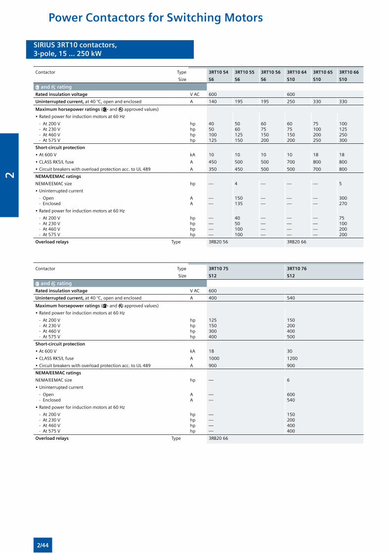
SIRIUS 3RT10 contactors,3-pole, 15 ... 250 kW
SIRIUS 3RT10 contactors,3-pole, 15 ... 250 kW
Contactor Type 3RT10 54 3RT10 55 3RT10 56 3RT10 64 3RT10 65 3RT10 66
Size S6 S6 S6 S10 S10 S10
and ratingRated insulation voltage V AC 600 600
Uninterrupted current, at 40 °C, open and enclosed A 140 195 195 250 330 330
Maximum horsepower ratings ( - and approved values)
• Rated power for induction motors at 60 Hz
- At 200 V - At 230 V - At 460 V - At 575 V
hphphphp
4050100125
5060125150
6075150200
6075150200
75100200250
100 125250300
Short-circuit protection
• At 600 V kA 10 10 10 10 18 18
• CLASS RK5/L fuse A 450 500 500 700 800 800
• Circuit breakers with overload protection acc. to UL 489 A 350 450 500 500 700 800
NEMA/EEMAC ratings
NEMA/EEMAC size hp — 4 — — — 5
• Uninterrupted current
- Open - Enclosed
AA
——
150135
——
——
——
300270
• Rated power for induction motors at 60 Hz
- At 200 V - At 230 V - At 460 V - At 575 V
hphphphp
————
4050100100
————
————
————
75100200200
Overload relays Type 3RB20 56 3RB20 66
Contactor Type 3RT10 75 3RT10 76
Size S12 S12
and ratingRated insulation voltage V AC 600
Uninterrupted current, at 40 °C, open and enclosed A 400 540
Maximum horsepower ratings ( - and approved values)
• Rated power for induction motors at 60 Hz
- At 200 V - At 230 V - At 460 V - At 575 V
hphphphp
125150300400
150200400500
Short-circuit protection
• At 600 V kA 18 30
• CLASS RK5/L fuse A 1000 1200
• Circuit breakers with overload protection acc. to UL 489 A 900 900
NEMA/EEMAC ratings
NEMA/EEMAC size hp — 6
• Uninterrupted current
- Open - Enclosed
AA
——
600540
• Rated power for induction motors at 60 Hz
- At 200 V - At 230 V - At 460 V - At 575 V
hphphphp
————
150200400400
Overload relays Type 3RB20 66
Power Contactors for Switching Motors
2/44
2
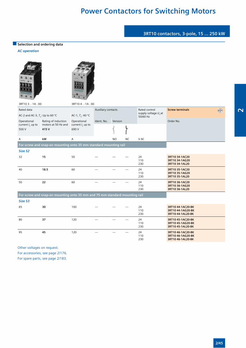
3RT10 contactors, 3-pole, 15 ... 250 kW 3RT10 contactors, 3-pole, 15 ... 250 kW
Selection and ordering data
AC operation
3RT10 3 . -1A . 00 3RT10 4 . -1A . 00
Rated data Auxiliary contacts Rated control supply voltage Us at 50/60 Hz
Screw terminals
AC-2 and AC-3, Tu: Up to 60 °C AC-1, Tu: 40 °C
Operational current Ie up to
500 V
Rating of induction motors at 50 Hz and
415 V
Operational current Ie up to
690 V
Ident. No. Version Order No.
A kW A NO NC V AC
For screw and snap-on mounting onto 35 mm standard mounting rail
Size S2
32 15 50 — — — 24110230
3RT10 34-1AC203RT10 34-1AG203RT10 34-1AL20
40 18.5 60 — — — 24110230
3RT10 35-1AC203RT10 35-1AG203RT10 35-1AL20
50 22 60 — — — 24110230
3RT10 36-1AC203RT10 36-1AG203RT10 36-1AL20
For screw and snap-on mounting onto 35 mm and 75 mm standard mounting rail
Size S3
65 30 100 — — — 24 110 230
3RT10 44-1AC20-8K3RT10 44-1AG20-8K3RT10 44-1AL20-8K
80 37 120 — — — 24 110 230
3RT10 45-1AC20-8K3RT10 45-1AG20-8K3RT10 45-1AL20-8K
95 45 120 — — — 24 110 230
3RT10 46-1AC20-8K3RT10 46-1AG20-8K3RT10 46-1AL20-8K
Other voltages on request.
For accessories, see page 2/176.
For spare parts, see page 2/183.
Power Contactors for Switching Motors
2/45
2
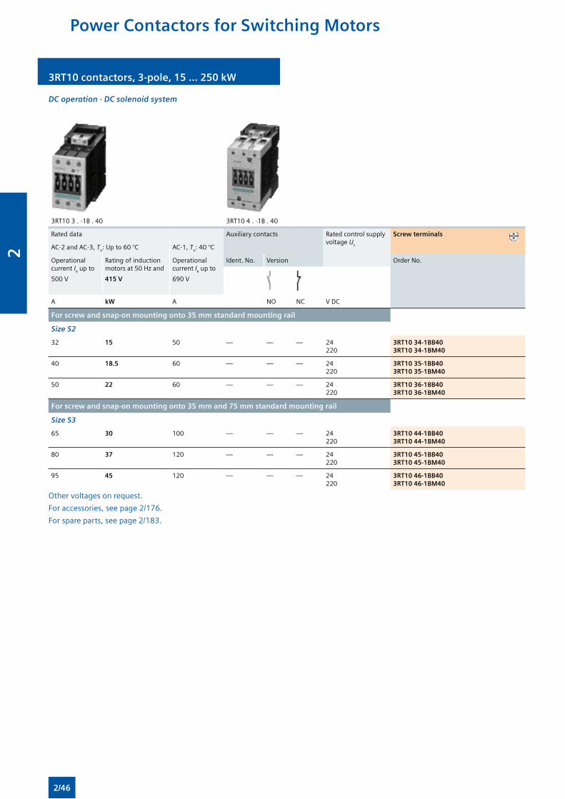
3RT10 contactors, 3-pole, 15 ... 250 kW 3RT10 contactors, 3-pole, 15 ... 250 kW
DC operation · DC solenoid system
3RT10 3 . -1B . 40 3RT10 4 . -1B . 40
Rated data Auxiliary contacts Rated control supply voltage Us
Screw terminals
AC-2 and AC-3, Tu: Up to 60 °C AC-1, Tu: 40 °C
Operational current Ie up to
500 V
Rating of induction motors at 50 Hz and
415 V
Operational current Ie up to
690 V
Ident. No. Version Order No.
A kW A NO NC V DC
For screw and snap-on mounting onto 35 mm standard mounting rail
Size S2
32 15 50 — — — 24 220
3RT10 34-1BB403RT10 34-1BM40
40 18.5 60 — — — 24 220
3RT10 35-1BB403RT10 35-1BM40
50 22 60 — — — 24 220
3RT10 36-1BB403RT10 36-1BM40
For screw and snap-on mounting onto 35 mm and 75 mm standard mounting rail
Size S3
65 30 100 — — — 24 220
3RT10 44-1BB403RT10 44-1BM40
80 37 120 — — — 24 220
3RT10 45-1BB403RT10 45-1BM40
95 45 120 — — — 24 220
3RT10 46-1BB403RT10 46-1BM40
Other voltages on request.
For accessories, see page 2/176.
For spare parts, see page 2/183.
Power Contactors for Switching Motors
2/46
2
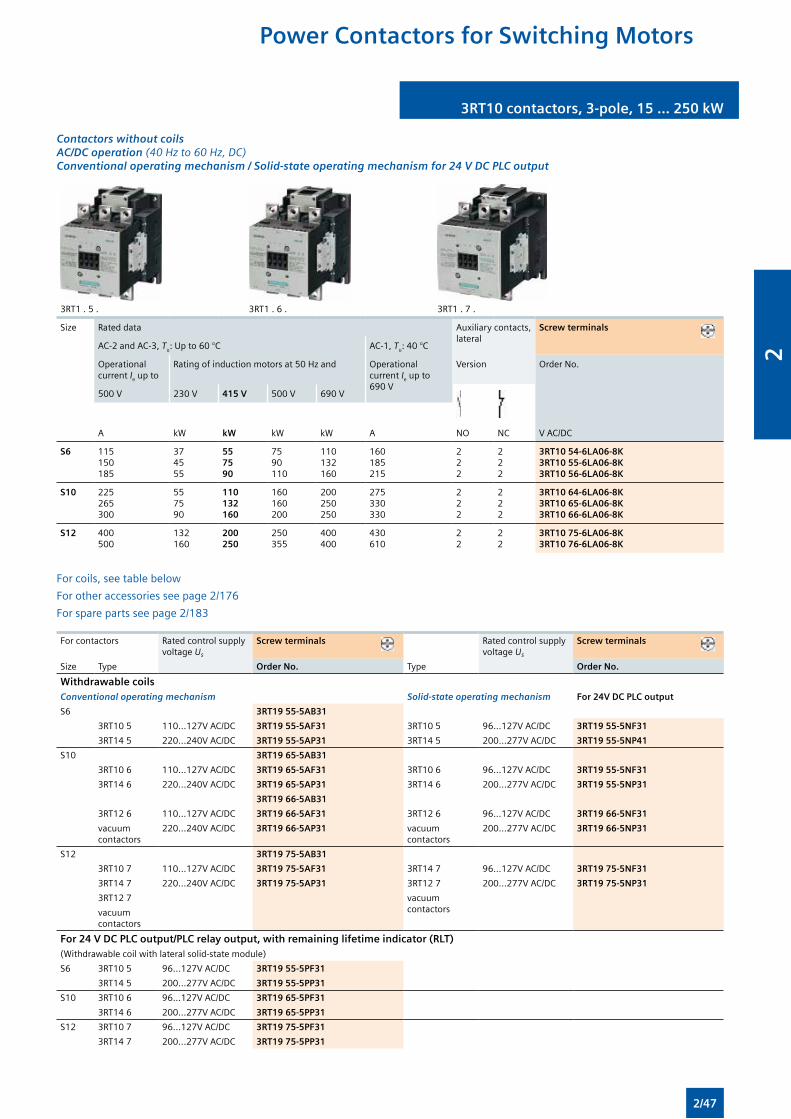
3RT10 contactors, 3-pole, 15 ... 250 kW3RT10 contactors, 3-pole, 15 ... 250 kW
Contactors without coils AC/DC operation (40 Hz to 60 Hz, DC) Conventional operating mechanism / Solid-state operating mechanism for 24 V DC PLC output
3RT1 . 5 . 3RT1 . 6 . 3RT1 . 7 .
Size Rated data Auxiliary contacts, lateral
Screw terminals
AC-2 and AC-3, Tu: Up to 60 °C AC-1, Tu: 40 °C
Operational current Ie up to
Rating of induction motors at 50 Hz and Operational current Ie up to690 V
Version Order No.
500 V 230 V 415 V 500 V 690 V
A kW kW kW kW A NO NC V AC/DC
S6 115150185
374555
55 75 90
7590110
110132160
160185215
222
222
3RT10 54-6LA06-8K3RT10 55-6LA06-8K3RT10 56-6LA06-8K
S10 225265300
557590
110 132 160
160160200
200250250
275330330
222
222
3RT10 64-6LA06-8K3RT10 65-6LA06-8K3RT10 66-6LA06-8K
S12 400500
132160
200 250
250355
400400
430610
22
22
3RT10 75-6LA06-8K3RT10 76-6LA06-8K
For coils, see table below
For other accessories see page 2/176
For spare parts see page 2/183
For contactors Rated control supply voltage Us
Screw terminals Rated control supply voltage Us
Screw terminals
Size Type Order No. Type Order No.
Withdrawable coils Conventional operating mechanism Solid-state operating mechanism For 24V DC PLC output
S6 3RT19 55-5AB31
3RT10 5 110...127V AC/DC 3RT19 55-5AF31 3RT10 5 96...127V AC/DC 3RT19 55-5NF31
3RT14 5 220...240V AC/DC 3RT19 55-5AP31 3RT14 5 200...277V AC/DC 3RT19 55-5NP41
S10 3RT19 65-5AB31
3RT10 6 110...127V AC/DC 3RT19 65-5AF31 3RT10 6 96...127V AC/DC 3RT19 55-5NF31
3RT14 6 220...240V AC/DC 3RT19 65-5AP31 3RT14 6 200...277V AC/DC 3RT19 55-5NP31
3RT19 66-5AB31
3RT12 6 110...127V AC/DC 3RT19 66-5AF31 3RT12 6 96...127V AC/DC 3RT19 66-5NF31
vacuum contactors
220...240V AC/DC 3RT19 66-5AP31 vacuum contactors
200...277V AC/DC 3RT19 66-5NP31
S12 3RT19 75-5AB31
3RT10 7 110...127V AC/DC 3RT19 75-5AF31 3RT14 7 96...127V AC/DC 3RT19 75-5NF31
3RT14 7 220...240V AC/DC 3RT19 75-5AP31 3RT12 7 200...277V AC/DC 3RT19 75-5NP31
3RT12 7 vacuum contactorsvacuum
contactors
For 24 V DC PLC output/PLC relay output, with remaining lifetime indicator (RLT)(Withdrawable coil with lateral solid-state module)
S6 3RT10 5 96...127V AC/DC 3RT19 55-5PF31
3RT14 5 200...277V AC/DC 3RT19 55-5PP31
S10 3RT10 6 96...127V AC/DC 3RT19 65-5PF31
3RT14 6 200...277V AC/DC 3RT19 65-5PP31
S12 3RT10 7 96...127V AC/DC 3RT19 75-5PF31
3RT14 7 200...277V AC/DC 3RT19 75-5PP31
Power Contactors for Switching Motors
2/47
2
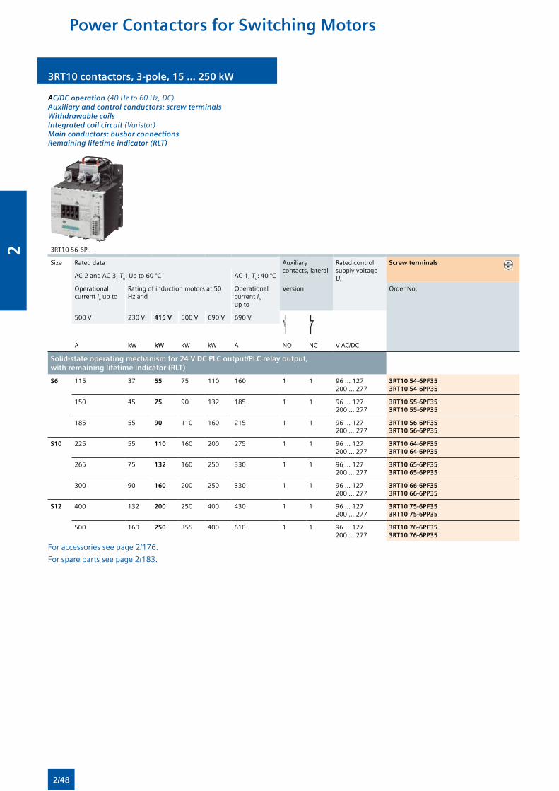
3RT10 contactors, 3-pole, 15 ... 250 kW 3RT10 contactors, 3-pole, 15 ... 250 kW
AC/DC operation (40 Hz to 60 Hz, DC) Auxiliary and control conductors: screw terminals Withdrawable coils Integrated coil circuit (Varistor) Main conductors: busbar connections Remaining lifetime indicator (RLT)
3RT10 56-6P . .
Size Rated data Auxiliary contacts, lateral
Rated control supply voltage Us
Screw terminals
AC-2 and AC-3, Tu: Up to 60 °C AC-1, Tu: 40 °C
Operational current Ie up to
Rating of induction motors at 50 Hz and
Operational current Ie up to
Version Order No.
500 V 230 V 415 V 500 V 690 V 690 V
A kW kW kW kW A NO NC V AC/DC
Solid-state operating mechanism for 24 V DC PLC output/PLC relay output, with remaining lifetime indicator (RLT)
S6 115 37 55 75 110 160 1 1 96 … 127200 … 277
3RT10 54-6PF353RT10 54-6PP35
150 45 75 90 132 185 1 1 96 … 127200 … 277
3RT10 55-6PF353RT10 55-6PP35
185 55 90 110 160 215 1 1 96 … 127200 … 277
3RT10 56-6PF353RT10 56-6PP35
S10 225 55 110 160 200 275 1 1 96 … 127200 … 277
3RT10 64-6PF353RT10 64-6PP35
265 75 132 160 250 330 1 1 96 … 127200 … 277
3RT10 65-6PF353RT10 65-6PP35
300 90 160 200 250 330 1 1 96 … 127200 … 277
3RT10 66-6PF353RT10 66-6PP35
S12 400 132 200 250 400 430 1 1 96 … 127200 … 277
3RT10 75-6PF353RT10 75-6PP35
500 160 250 355 400 610 1 1 96 … 127200 … 277
3RT10 76-6PF353RT10 76-6PP35
For accessories see page 2/176.
For spare parts see page 2/183.
Power Contactors for Switching Motors
2/48
2
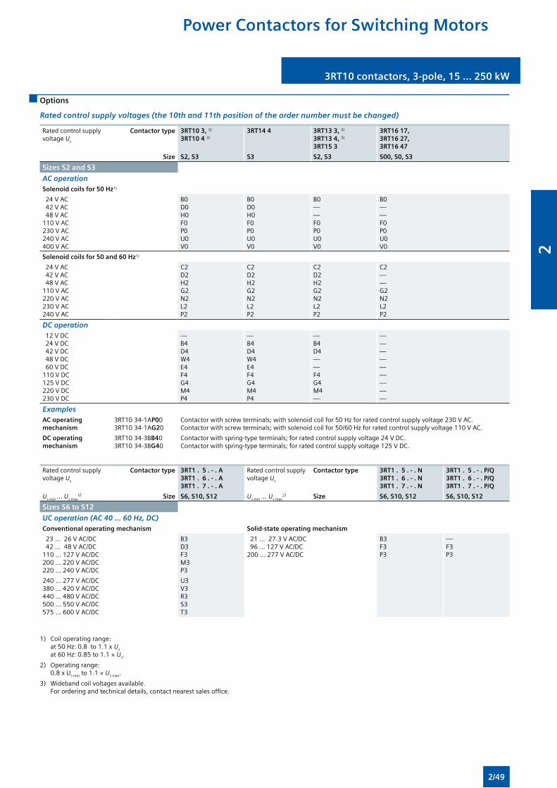
3RT10 contactors, 3-pole, 15 ... 250 kW3RT10 contactors, 3-pole, 15 ... 250 kW
Options
Rated control supply voltages (the 10th and 11th position of the order number must be changed)
Rated control supply voltage Us
Contactor type 3RT10 3, 3) 3RT10 4 3)
3RT14 4 3RT13 3, 3) 3RT13 4, 3) 3RT15 3
3RT16 17, 3RT16 27, 3RT16 47
Size S2, S3 S3 S2, S3 S00, S0, S3
Sizes S2 and S3
AC operationSolenoid coils for 50 Hz1)
24 V AC 42 V AC 48 V AC110 V AC230 V AC240 V AC400 V AC
B0D0H0F0P0U0V0
B0D0H0F0P0U0V0
B0——F0P0U0V0
B0——F0P0U0V0
Solenoid coils for 50 and 60 Hz1)
24 V AC 42 V AC 48 V AC110 V AC220 V AC230 V AC240 V AC
C2D2H2G2N2L2P2
C2D2H2G2N2L2P2
C2D2H2G2N2L2P2
C2——G2N2L2P2
DC operation 12 V DC24 V DC 42 V DC 48 V DC 60 V DC110 V DC125 V DC220 V DC230 V DC
—B4D4W4E4F4G4M4P4
—B4D4W4E4F4G4M4P4
—B4D4——F4G4M4—
—————————
ExamplesAC operating mechanism
3RT10 34-1AP003RT10 34-1AG20
Contactor with screw terminals; with solenoid coil for 50 Hz for rated control supply voltage 230 V AC.Contactor with screw terminals; with solenoid coil for 50/60 Hz for rated control supply voltage 110 V AC.
DC operating mechanism
3RT10 34-3BB403RT10 34-3BG40
Contactor with spring-type terminals; for rated control supply voltage 24 V DC.Contactor with spring-type terminals; for rated control supply voltage 125 V DC.
Rated control supply voltage Us
Contactor type 3RT1 . 5 . - . A 3RT1 . 6 . - . A 3RT1 . 7 . - . A
Rated control supply voltage Us
Contactor type 3RT1 . 5 . - . N 3RT1 . 6 . - . N 3RT1 . 7 . - . N
3RT1 . 5 . - . P/Q 3RT1 . 6 . - . P/Q 3RT1 . 7 . - . P/Q
Us min ... Us max5) Size S6, S10, S12 Us min ... Us max
2) Size S6, S10, S12 S6, S10, S12
Sizes S6 to S12
UC operation (AC 40 ... 60 Hz, DC)Conventional operating mechanism Solid-state operating mechanism
23 ... 26 V AC/DC 42 ... 48 V AC/DC110 ... 127 V AC/DC200 ... 220 V AC/DC220 ... 240 V AC/DC
B3D3F3M3P3
21 ... 27.3 V AC/DC 96 ... 127 V AC/DC200 ... 277 V AC/DC
B3F3P3
—F3 P3
240 ... 277 V AC/DC380 ... 420 V AC/DC440 ... 480 V AC/DC500 ... 550 V AC/DC575 ... 600 V AC/DC
U3V3R3S3T3
1) Coil operating range: at 50 Hz: 0.8 to 1.1 x Us
at 60 Hz: 0.85 to 1.1 × Us.
2) Operating range: 0.8 x Us min to 1.1 × Us max.
3) Wideband coil voltages available. For ordering and technical details, contact nearest sales office.
Power Contactors for Switching Motors
2/49
2
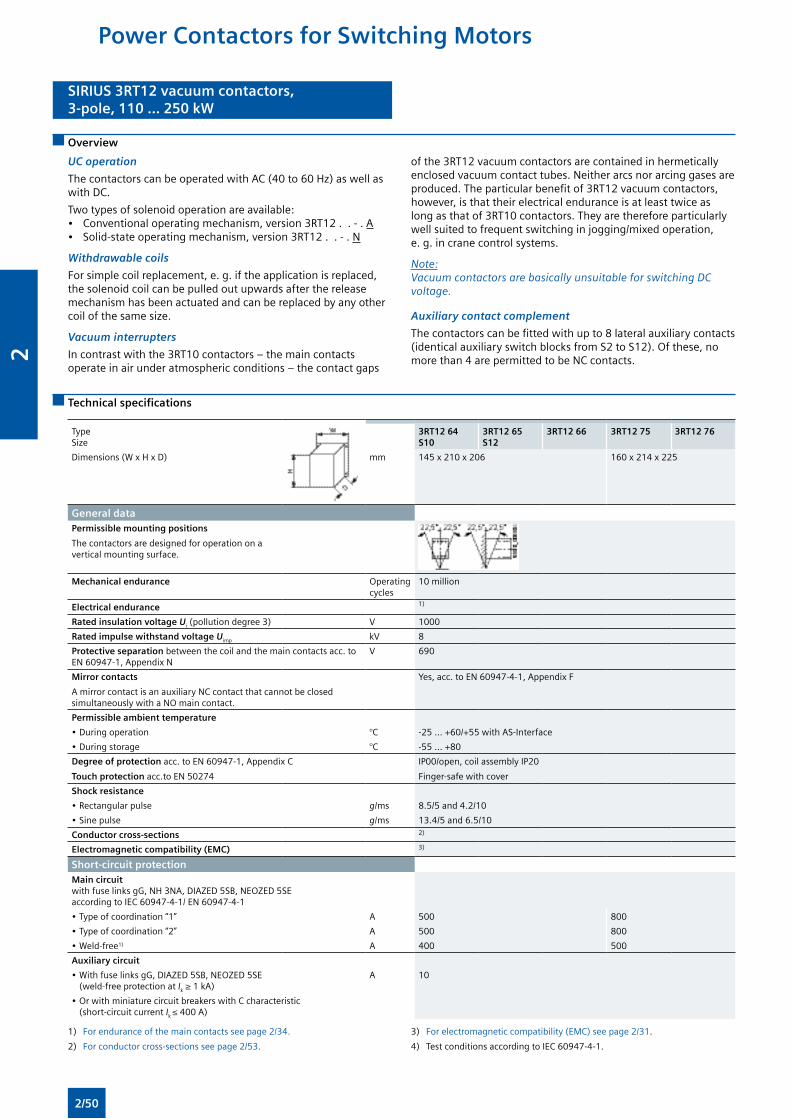
SIRIUS 3RT12 vacuum contactors,3-pole, 110 ... 250 kW
SIRIUS 3RT12 vacuum contactors,3-pole, 110 ... 250 kW
Overview
UC operation
The contactors can be operated with AC (40 to 60 Hz) as well as with DC.
Two types of solenoid operation are available:• Conventional operating mechanism, version 3RT12 . . - . A• Solid-state operating mechanism, version 3RT12 . . - . N
Withdrawable coils
For simple coil replacement, e. g. if the application is replaced, the solenoid coil can be pulled out upwards after the release mechanism has been actuated and can be replaced by any other coil of the same size.
Vacuum interrupters
In contrast with the 3RT10 contactors – the main contacts operate in air under atmospheric conditions – the contact gaps
of the 3RT12 vacuum contactors are contained in hermetically enclosed vacuum contact tubes. Neither arcs nor arcing gases are produced. The particular benefit of 3RT12 vacuum contactors, however, is that their electrical endurance is at least twice as long as that of 3RT10 contactors. They are therefore particularly well suited to frequent switching in jogging/mixed operation, e. g. in crane control systems.
Note:Vacuum contactors are basically unsuitable for switching DC voltage.
Auxiliary contact complement
The contactors can be fitted with up to 8 lateral auxiliary contacts (identical auxiliary switch blocks from S2 to S12). Of these, no more than 4 are permitted to be NC contacts.
Technical specifications
TypeSize
3RT12 64S10
3RT12 65S12
3RT12 66 3RT12 75 3RT12 76
Dimensions (W x H x D) mm 145 x 210 x 206 160 x 214 x 225
General dataPermissible mounting positions
The contactors are designed for operation on a vertical mounting surface.
Mechanical endurance Operating cycles
10 million
Electrical endurance 1)
Rated insulation voltage Ui (pollution degree 3) V 1000
Rated impulse withstand voltage Uimp kV 8
Protective separation between the coil and the main contacts acc. to EN 60947-1, Appendix N
V 690
Mirror contacts
A mirror contact is an auxiliary NC contact that cannot be closed simultaneously with a NO main contact.
Yes, acc. to EN 60947-4-1, Appendix F
Permissible ambient temperature
• During operation °C -25 ... +60/+55 with AS-Interface
• During storage °C -55 ... +80
Degree of protection acc. to EN 60947-1, Appendix C
Touch protection acc.to EN 50274
IP00/open, coil assembly IP20
Finger-safe with cover
Shock resistance
• Rectangular pulse g/ms 8.5/5 and 4.2/10
• Sine pulse g/ms 13.4/5 and 6.5/10
Conductor cross-sections 2)
Electromagnetic compatibility (EMC) 3)
Short-circuit protectionMain circuit with fuse links gG, NH 3NA, DIAZED 5SB, NEOZED 5SE according to IEC 60947-4-1/ EN 60947-4-1
• Type of coordination “1” A 500 800
• Type of coordination “2” A 500 800
• Weld-free1) A 400 500
Auxiliary circuit
• With fuse links gG, DIAZED 5SB, NEOZED 5SE (weld-free protection at Ik ≥ 1 kA)
A 10
• Or with miniature circuit breakers with C characteristic (short-circuit current Ik ≤ 400 A)
1) For endurance of the main contacts see page 2/34.
2) For conductor cross-sections see page 2/53.
3) For electromagnetic compatibility (EMC) see page 2/31.
4) Test conditions according to IEC 60947-4-1.
Power Contactors for Switching Motors
2/50
2
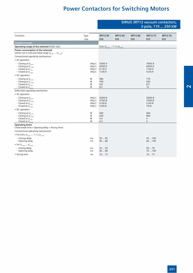
SIRIUS 3RT12 vacuum contactors,3-pole, 110 ... 250 kW
SIRIUS 3RT12 vacuum contactors,3-pole, 110 ... 250 kW
Contactor Type 3RT12 64 3RT12 65 3RT12 66 3RT12 75 3RT12 76
Size S10 S10 S10 S12 S12
Control circuitOperating range of the solenoid AC/DC (UC) 0.8 x Us min ... 1.1 x Us max
Power consumption of the solenoid (when coil is cool and rated range Us min ... Us max)
Conventional operating mechanisms
• AC operation
- Closing at Us min
- Closing at Us max
- Closed at Us min
- Closed at Us max
VA/p.f.VA/p.f.VA/p.f.VA/p.f.
530/0.9630/0.96.1/0.97.4/0.9
700/0.9830/0.97.6/0.99.2/0.9
• DC operation
- Closing at Us min
- Closing at Us max
- Closed at Us min
- Closed at Us max
WWWW
5807006.88.2
7709208.510
Solid-state operating mechanism
• AC operation
- Closing at Us min
- Closing at Us max
- Closed at Us min
- Closed at Us max
VA/p.f.VA/p.f.VA/p.f.VA/p.f.
420/0.8570/0.84.3/0.85.6/0.8
560/0.8750/0.85.4/0.87/0.8
• DC operation
- Closing at Us min
- Closing at Us max
- Closed at Us min
- Closed at Us max
WWWW
4606303.44.2
60080045
Operating times (Total break time = Opening delay + Arcing time)
Conventional operating mechanisms
• For 0.8 x Us min ... 1.1 x Us max
- Closing delay - Opening delay
msms
30 ... 9540 ... 80
45 ... 10060 ... 100
• For Us min ... Us max
- Closing delay - Opening delay
msms
35 ... 5050 ... 80
50 ... 7070 ... 100
• Arcing time ms 10 ... 15 10 ... 15
Power Contactors for Switching Motors
2/51
2
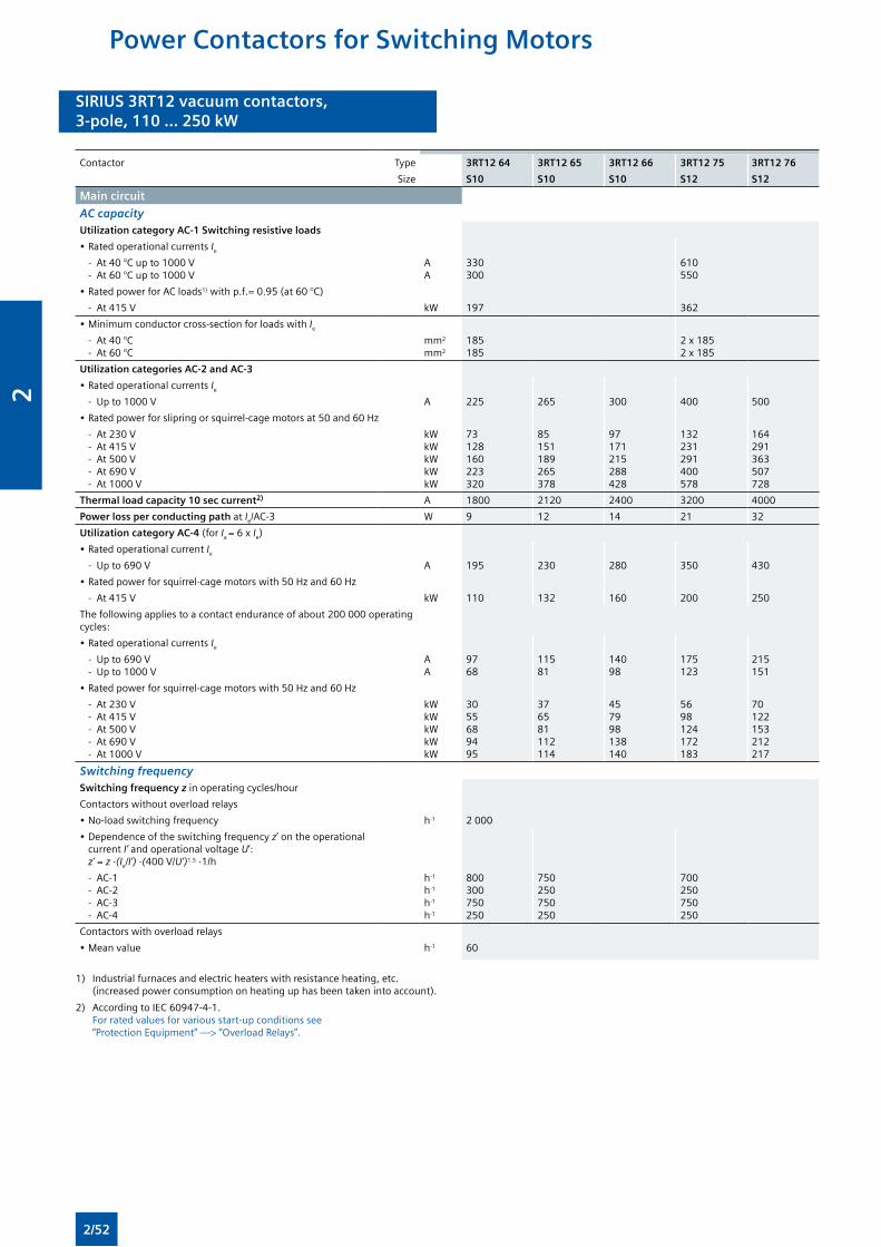
SIRIUS 3RT12 vacuum contactors,3-pole, 110 ... 250 kW
SIRIUS 3RT12 vacuum contactors,3-pole, 110 ... 250 kW
Contactor Type 3RT12 64 3RT12 65 3RT12 66 3RT12 75 3RT12 76
Size S10 S10 S10 S12 S12
Main circuit
AC capacityUtilization category AC-1 Switching resistive loads
• Rated operational currents Ie
- At 40 °C up to 1000 V - At 60 °C up to 1000 V
AA
330300
610550
• Rated power for AC loads1) with p.f.= 0.95 (at 60 °C)
- At 415 V kW 197 362
• Minimum conductor cross-section for loads with Ie
- At 40 °C - At 60 °C
mm2
mm2
185185
2 x 1852 x 185
Utilization categories AC-2 and AC-3
• Rated operational currents Ie
- Up to 1000 V A 225 265 300 400 500
• Rated power for slipring or squirrel-cage motors at 50 and 60 Hz
- At 230 V - At 415 V - At 500 V - At 690 V - At 1000 V
kWkWkWkWkW
73128160223320
85151189265378
97171215288428
132231291400578
164291363507728
Thermal load capacity 10 sec current2) A 1800 2120 2400 3200 4000
Power loss per conducting path at Ie/AC-3 W 9 12 14 21 32
Utilization category AC-4 (for Ia = 6 x Ie)
• Rated operational current Ie
- Up to 690 V A 195 230 280 350 430
• Rated power for squirrel-cage motors with 50 Hz and 60 Hz
- At 415 V kW 110 132 160 200 250
The following applies to a contact endurance of about 200 000 operating cycles:
• Rated operational currents Ie
- Up to 690 V - Up to 1000 V
AA
9768
11581
14098
175123
215151
• Rated power for squirrel-cage motors with 50 Hz and 60 Hz
- At 230 V - At 415 V - At 500 V - At 690 V - At 1000 V
kWkWkWkWkW
3055689495
376581112114
457998138140
5698124172183
70122153212217
Switching frequencySwitching frequency z in operating cycles/hour
Contactors without overload relays
• No-load switching frequency h-1 2 000
• Dependence of the switching frequency z’ on the operational current I’ and operational voltage U’: z’ = z ·(Ie/I’) ·(400 V/U’)1.5 ·1/h
- AC-1 - AC-2 - AC-3 - AC-4
h-1
h-1
h-1
h-1
800300750250
750250750250
700250750250
Contactors with overload relays
• Mean value h-1 60
1) Industrial furnaces and electric heaters with resistance heating, etc. (increased power consumption on heating up has been taken into account).
2) According to IEC 60947-4-1. For rated values for various start-up conditions see “Protection Equipment” —> “Overload Relays”.
Power Contactors for Switching Motors
2/52
2
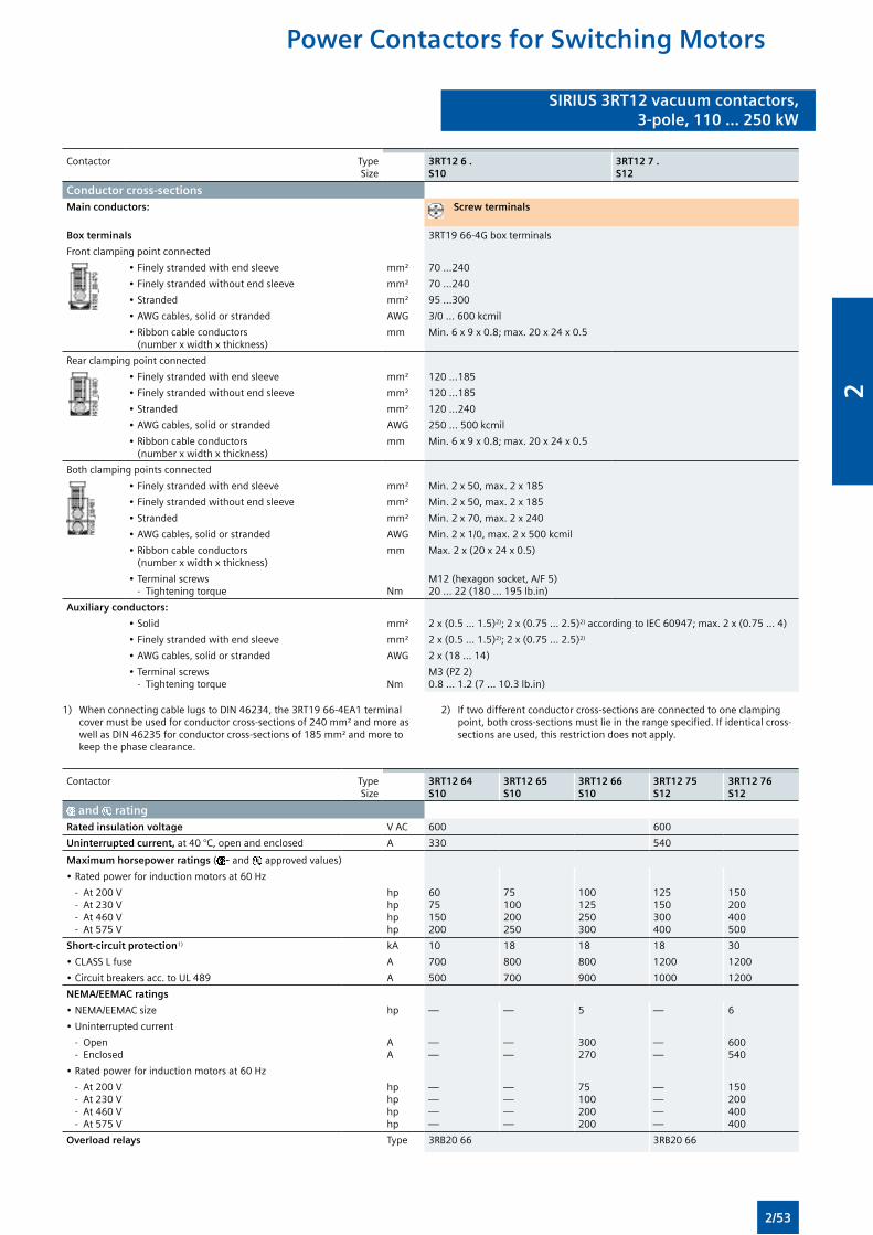
SIRIUS 3RT12 vacuum contactors,3-pole, 110 ... 250 kW
SIRIUS 3RT12 vacuum contactors,3-pole, 110 ... 250 kW
Contactor TypeSize
3RT12 6 . S10
3RT12 7 . S12
Conductor cross-sectionsMain conductors: Screw terminals
Box terminals 3RT19 66-4G box terminals
Front clamping point connected
• Finely stranded with end sleeve mm² 70 ...240
• Finely stranded without end sleeve mm² 70 ...240
• Stranded mm² 95 ...300
• AWG cables, solid or stranded AWG 3/0 ... 600 kcmil
• Ribbon cable conductors (number x width x thickness)
mm Min. 6 x 9 x 0.8; max. 20 x 24 x 0.5
Rear clamping point connected
• Finely stranded with end sleeve mm² 120 ...185
• Finely stranded without end sleeve mm² 120 ...185
• Stranded mm² 120 ...240
• AWG cables, solid or stranded AWG 250 ... 500 kcmil
• Ribbon cable conductors (number x width x thickness)
mm Min. 6 x 9 x 0.8; max. 20 x 24 x 0.5
Both clamping points connected
• Finely stranded with end sleeve mm² Min. 2 x 50, max. 2 x 185
• Finely stranded without end sleeve mm² Min. 2 x 50, max. 2 x 185
• Stranded mm² Min. 2 x 70, max. 2 x 240
• AWG cables, solid or stranded AWG Min. 2 x 1/0, max. 2 x 500 kcmil
• Ribbon cable conductors (number x width x thickness)
mm Max. 2 x (20 x 24 x 0.5)
• Terminal screws - Tightening torque
Nm
M12 (hexagon socket, A/F 5)20 ... 22 (180 ... 195 lb.in)
Auxiliary conductors:
• Solid mm² 2 x (0.5 ... 1.5)2); 2 x (0.75 ... 2.5)2) according to IEC 60947; max. 2 x (0.75 ... 4)
• Finely stranded with end sleeve mm² 2 x (0.5 ... 1.5)2); 2 x (0.75 ... 2.5)2)
• AWG cables, solid or stranded AWG 2 x (18 ... 14)
• Terminal screws - Tightening torque
Nm
M3 (PZ 2)0.8 ... 1.2 (7 ... 10.3 lb.in)
1) When connecting cable lugs to DIN 46234, the 3RT19 66-4EA1 terminal cover must be used for conductor cross-sections of 240 mm² and more as well as DIN 46235 for conductor cross-sections of 185 mm² and more to keep the phase clearance.
2) If two different conductor cross-sections are connected to one clamping point, both cross-sections must lie in the range specified. If identical cross-sections are used, this restriction does not apply.
Contactor TypeSize
3RT12 64S10
3RT12 65S10
3RT12 66S10
3RT12 75S12
3RT12 76S12
and ratingRated insulation voltage V AC 600 600
Uninterrupted current, at 40 °C, open and enclosed A 330 540
Maximum horsepower ratings ( - and approved values)
• Rated power for induction motors at 60 Hz
- At 200 V - At 230 V - At 460 V - At 575 V
hphphphp
6075150200
75100200250
100125250300
125150300400
150200400500
Short-circuit protection1) kA 10 18 18 18 30
• CLASS L fuse A 700 800 800 1200 1200
• Circuit breakers acc. to UL 489 A 500 700 900 1000 1200
NEMA/EEMAC ratings
• NEMA/EEMAC size hp — — 5 — 6
• Uninterrupted current
- Open - Enclosed
AA
——
——
300270
——
600540
• Rated power for induction motors at 60 Hz
- At 200 V - At 230 V - At 460 V - At 575 V
hphphphp
————
————
75100200200
————
150200400400
Overload relays Type 3RB20 66 3RB20 66
Power Contactors for Switching Motors
2/53
2
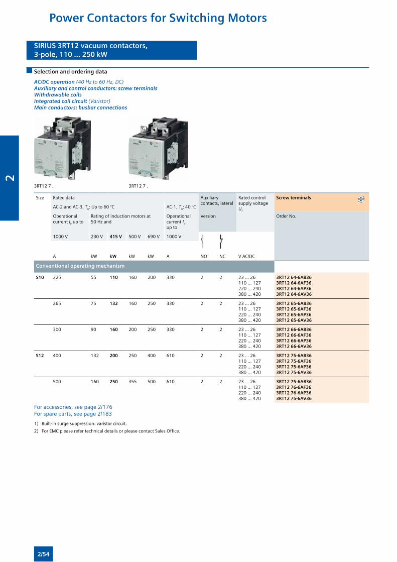
SIRIUS 3RT12 vacuum contactors,3-pole, 110 ... 250 kW
SIRIUS 3RT12 vacuum contactors,3-pole, 110 ... 250 kW
Selection and ordering data
AC/DC operation (40 Hz to 60 Hz, DC) Auxiliary and control conductors: screw terminals Withdrawable coils Integrated coil circuit (Varistor) Main conductors: busbar connections
3RT12 7 . 3RT12 7 .
Size Rated data Auxiliary contacts, lateral
Rated control supply voltage Us
Screw terminals
AC-2 and AC-3, Tu: Up to 60 °C AC-1, Tu: 40 °C
Operational current Ie up to
Rating of induction motors at 50 Hz and
Operational current Ie up to
Version Order No.
1000 V 230 V 415 V 500 V 690 V 1000 V
A kW kW kW kW A NO NC V AC/DC
Conventional operating mechanism
S10 225 55 110 160 200 330 2 2 23 … 26110 … 127220 … 240380 … 420
3RT12 64-6AB363RT12 64-6AF36 3RT12 64-6AP36 3RT12 64-6AV36
265 75 132 160 250 330 2 2 23 … 26110 … 127220 … 240380 … 420
3RT12 65-6AB363RT12 65-6AF363RT12 65-6AP363RT12 65-6AV36
300 90 160 200 250 330 2 2 23 … 26110 … 127220 … 240380 … 420
3RT12 66-6AB363RT12 66-6AF363RT12 66-6AP363RT12 66-6AV36
S12 400 132 200 250 400 610 2 2 23 … 26110 … 127220 … 240380 … 420
3RT12 75-6AB363RT12 75-6AF363RT12 75-6AP363RT12 75-6AV36
500 160 250 355 500 610 2 2 23 … 26110 … 127220 … 240380 … 420
3RT12 75-6AB363RT12 76-6AF363RT12 76-6AP363RT12 75-6AV36
For accessories, see page 2/176 For spare parts, see page 2/183
1) Built-in surge suppression: varistor circuit.
2) For EMC please refer technical details or please contact Sales Office.
Power Contactors for Switching Motors
2/54
2
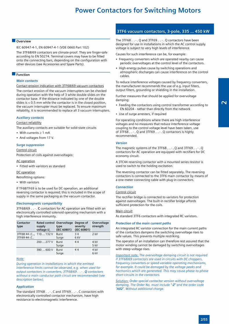
3TF6 vacuum contactors, 3-pole, 335 ... 450 kW3TF6 vacuum contactors, 3-pole, 335 ... 450 kW
Overview
IEC 60947-4-1, EN 60947-4-1 (VDE 0660 Part 102)
The 3TF68/69 contactors are climate-proof. They are finger-safe according to EN 50274. Terminal covers may have to be fitted onto the connecting bars, depending on the configuration with other devices (see Accessories and Spare Parts).
Function
Main contacts
Contact erosion indication with 3TF68/69 vacuum contactors
The contact erosion of the vacuum interrupters can be checked during operation with the help of 3 white double slides on the contactor base. If the distance indicated by one of the double slides is < 0.5 mm while the contactor is in the closed position, the vacuum interrupter must be replaced. To ensure maximum reliability, it is recommended to replace all 3 vacuum interrupters.
Auxiliary contacts
Contact reliability
The auxiliary contacts are suitable for solid-state circuits
• With currents ≥ 1 mA
• And voltages from 17 V.
Surge suppression
Control circuit
Protection of coils against overvoltages:
AC operation
• Fitted with varistors as standard
DC operation
Retrofitting options:
• With varistors
If TF68/TF69 is to be used for DC operation, an additional reversing contactor is required; this is included in the scope of supply in the same packaging as the vacuum contactor.
Electromagnetic compatibility
3TF68/69 . . - . C contactors for AC operation are fitted with an electronically controlled solenoid operating mechanism with a high interference immunity.
Contactor type
Rated control supply voltage Us
Overvoltage type (IEC 60801)
Degree of severity(IEC 60801)
Overvoltage strength
3TF68 44-.C..,3TF69 44-.C..
110 ... 132 V BurstSurge
3 46 kV
2 kV
200 ... 277 V BurstSurge
4 4 4 kV5 kV
380 ... 600 V BurstSurge
4 4 4 kV6 kV
Note:
During operation in installations in which the emitted interference limits cannot be observed, e.g. when used for output contactors in converters, 3TF68/69 . . - . Q contactors without a main conductor path circuit are recommended (see description below).
Application
The standard 3TF68 . . - . C and 3TF69 . . - . C contactors with electronically controlled contactor mechanism, have high resistance to electromagnetic interference.
The 3TF68 . . - . Q and 3TF69 . . - . Q contactors have been designed for use in installations in which the AC control supply voltage is subject to very high levels of interference.
Causes for such interference can be, for example:
• Frequency converters which are operated nearby can cause periodic overvoltages at the control level of the contactors.
• High-energy pulses cause by switching operations and atmospheric discharges can cause interference on the control cables.
To reduce interference voltages caused by frequency converters, the manufacturer recommends the use of e.g. input filters, output filters, grounding or shielding in the installation.
Further measures that should be applied for overvoltage damping:
• Feeding the contactors using control transformer according to EN 60204 - rather than directly from the network
• Use of surge arresters, if required
For operating conditions where there are high interference voltages and no measures that reduce interference voltage coupling to the control voltage level have been taken, use of 3TF68 . . - . Q and 3TF69 . . - . Q contactors is highly recommended.
Version
The magnetic systems of the 3TF68 . . - . Q and 3TF69 . . - . Q contactors for AC operation are equipped with rectifiers for DC economy circuit.
A 3TC44 reversing contactor with a mounted series resistor is used to switch to the holding excitation.
The reversing contactor can be fitted separately. The reversing contactors is connected to the 3TF6 main contactor by means of a one-meter connecting cable with plug-in connectors.
Connection
Control circuit
The rectifier bridge is connected to varistors for protection against overvoltages. The built-in rectifier bridge affords sufficient protection for the coils.
Main circuit
As standard 3TF6 contactors with integrated RC varistors.
Protection of the main current paths
An integrated RC varistor connection for the main current paths of the contactors dampens the switching overvoltage rises to safe values. This prevents multiple restriking.
The operator of an installation can therefore rest assured that the motor winding cannot be damaged by switching overvoltages with steep voltage rises.
Important note: The overvoltage damping circuit is not required if 3TF68/69 contactors are used in circuits with DC choppers, frequency converters or speed-variable operating mechanisms, for example. It could be damaged by the voltage peaks and harmonics which are generated. This may cause phase-to-phase short-circuits in the contactors.
Solution: Order special contactor version without overvoltage damping. The Order No. must include “-Z” and the order code “A02”. Without additional charge.
Power Contactors for Switching Motors
2/55
2
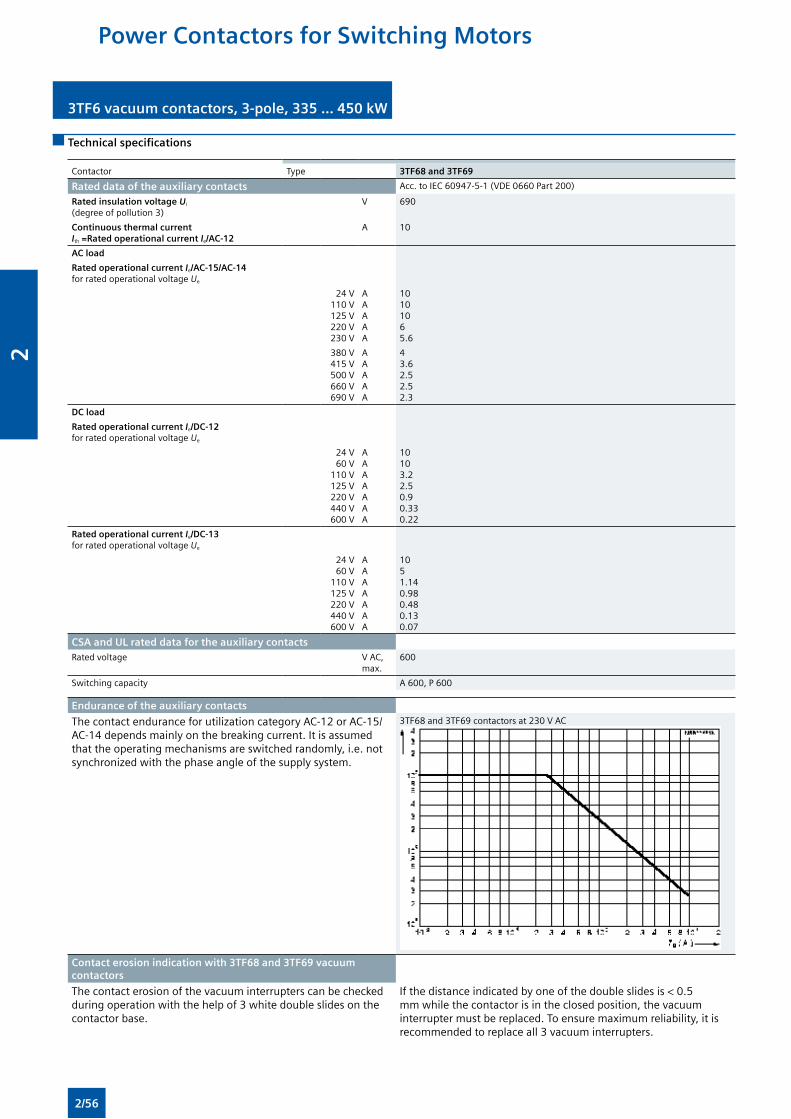
3TF6 vacuum contactors, 3-pole, 335 ... 450 kW 3TF6 vacuum contactors, 3-pole, 335 ... 450 kW
Technical specifications
Contactor Type 3TF68 and 3TF69
Rated data of the auxiliary contacts Acc. to IEC 60947-5-1 (VDE 0660 Part 200)
Rated insulation voltage Ui
(degree of pollution 3)V 690
Continuous thermal current Ith =Rated operational current Ie/AC-12
A 10
AC load
Rated operational current Ie/AC-15/AC-14for rated operational voltage Ue
24 V110 V125 V220 V230 V
AAAAA
10101065.6
380 V415 V500 V660 V690 V
AAAAA
43.62.52.52.3
DC load
Rated operational current Ie/DC-12 for rated operational voltage Ue
24 V60 V
110 V125 V220 V440 V600 V
AAAAAAA
10103.22.50.90.330.22
Rated operational current Ie/DC-13 for rated operational voltage Ue
24 V60 V
110 V125 V220 V440 V600 V
AAAAAAA
1051.140.980.480.130.07
CSA and UL rated data for the auxiliary contactsRated voltage V AC,
max.600
Switching capacity A 600, P 600
Endurance of the auxiliary contacts
The contact endurance for utilization category AC-12 or AC-15/AC-14 depends mainly on the breaking current. It is assumed that the operating mechanisms are switched randomly, i.e. not synchronized with the phase angle of the supply system.
3TF68 and 3TF69 contactors at 230 V AC
Contact erosion indication with 3TF68 and 3TF69 vacuum contactors
The contact erosion of the vacuum interrupters can be checked during operation with the help of 3 white double slides on the contactor base.
If the distance indicated by one of the double slides is < 0.5 mm while the contactor is in the closed position, the vacuum interrupter must be replaced. To ensure maximum reliability, it is recommended to replace all 3 vacuum interrupters.
Power Contactors for Switching Motors
2/56
2
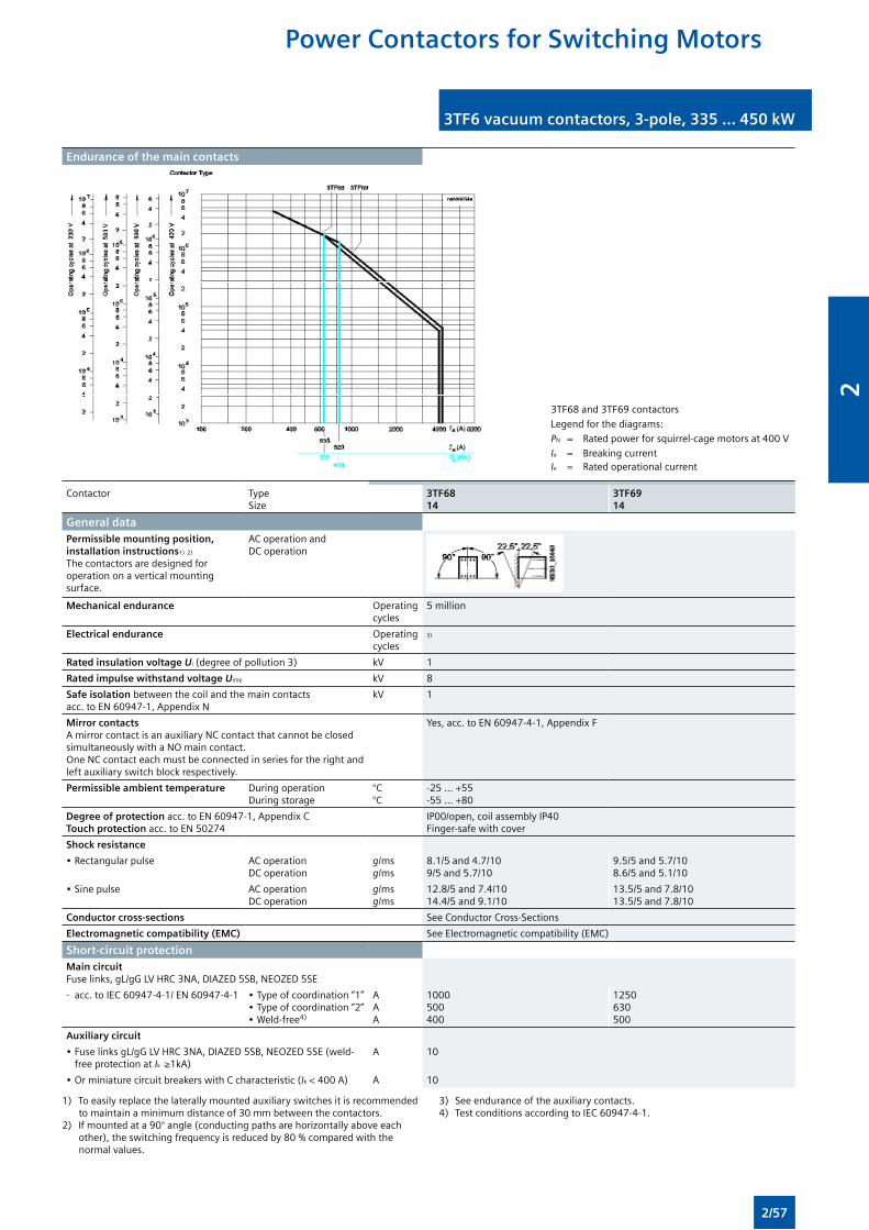
3TF6 vacuum contactors, 3-pole, 335 ... 450 kW3TF6 vacuum contactors, 3-pole, 335 ... 450 kW
Endurance of the main contacts
3TF68 and 3TF69 contactors
Legend for the diagrams:
PN = Rated power for squirrel-cage motors at 400 V
Ia = Breaking currentIe = Rated operational current
Contactor TypeSize
3TF6814
3TF6914
General data
Permissible mounting position, installation instructions1) 2) The contactors are designed for operation on a vertical mounting surface.
AC operation and DC operation
Mechanical endurance Operating cycles
5 million
Electrical endurance Operating cycles
3)
Rated insulation voltage Ui (degree of pollution 3) kV 1
Rated impulse withstand voltage Uimp kV 8
Safe isolation between the coil and the main contacts acc. to EN 60947-1, Appendix N
kV 1
Mirror contacts A mirror contact is an auxiliary NC contact that cannot be closed simultaneously with a NO main contact. One NC contact each must be connected in series for the right and left auxiliary switch block respectively.
Yes, acc. to EN 60947-4-1, Appendix F
Permissible ambient temperature During operationDuring storage
°C°C
-25 ... +55-55 ... +80
Degree of protection acc. to EN 60947-1, Appendix CTouch protection acc. to EN 50274
IP00/open, coil assembly IP40Finger-safe with cover
Shock resistance
• Rectangular pulse AC operationDC operation
g/msg/ms
8.1/5 and 4.7/109/5 and 5.7/10
9.5/5 and 5.7/108.6/5 and 5.1/10
• Sine pulse AC operationDC operation
g/msg/ms
12.8/5 and 7.4/1014.4/5 and 9.1/10
13.5/5 and 7.8/1013.5/5 and 7.8/10
Conductor cross-sections See Conductor Cross-Sections
Electromagnetic compatibility (EMC) See Electromagnetic compatibility (EMC)
Short-circuit protectionMain circuit Fuse links, gL/gG LV HRC 3NA, DIAZED 5SB, NEOZED 5SE
- acc. to IEC 60947-4-1/ EN 60947-4-1 • Type of coordination “1”• Type of coordination “2”• Weld-free4)
AAA
1000500400
1250630500
Auxiliary circuit
• Fuse links gL/gG LV HRC 3NA, DIAZED 5SB, NEOZED 5SE (weld-free protection at Ik ≥1kA)
A 10
• Or miniature circuit breakers with C characteristic (Ik < 400 A) A 10
1) To easily replace the laterally mounted auxiliary switches it is recommended to maintain a minimum distance of 30 mm between the contactors.
2) If mounted at a 90° angle (conducting paths are horizontally above each other), the switching frequency is reduced by 80 % compared with the normal values.
3) See endurance of the auxiliary contacts.4) Test conditions according to IEC 60947-4-1.
Power Contactors for Switching Motors
2/57
2

3TF6 vacuum contactors, 3-pole, 335 ... 450 kW 3TF6 vacuum contactors, 3-pole, 335 ... 450 kW
Contactor TypeSize
3TF6814
3TF6914
ControlMagnetic coil operating range 0.8 x Us min ... 1.1 x Us max
Power consumption of the magnetic coils (when coil is cold and 1.0 x Us)• AC operation, Us max - Closing
- ClosedVA/p.f.VA/p.f.
1850/149/0.15
950/0.9830.6/0.31
• AC operation, Us min - Closing- Closed
VA/p.f.VA/p.f.
1200/113.5/0.47
600/0.9812.9/0.43
• DC economy circuit1) - Closing at 24 V- Closed
WW
101028
96020.6
Operating times at 0,8 ... 1.1 x Us
(Total break time = Opening delay + Arcing time)(Values apply to cold and warm coil)
• AC operation - Closing delay- Opening delay
msms
70 ... 120 (22 ... 65)2)
70 ... 10080 ... 12070 ... 80
• DC economy circuit - Closing delay- Opening delay
msms
76 ... 11050
86 ... 28019 ... 25
• Arcing time ms 10 ... 15 10Operating times at 1.0 x U s (Total break time = Opening delay + Arcing time)• AC operation - Closing delay
- Opening delaymsms
80 ... 100 (30 ... 45)2)
70 ... 10085 ... 10070
• DC economy circuit - Closing delay- Opening delay
msms
80 ... 9050
90 ... 12519 ... 25
Minimum command duration for closing
StandardReduced make-time
msms
12090
120—
Minimum interval time between two ON commands ms 100 300
Main circuitAC capacityUtilization category AC-1Switching resistive loadsRated operational currents Ie at 40 °C up to 690 V
at 55 °C up to 690 Vat 55 °C up to 1000 V
AAA
700630450
910850800
Rated power for AC loads with p.f. = 0.95 at 55°C 415 V kW 415 558Minimum conductor cross-sections for loads with Ie
at 40°Cat 55°C
mm2
mm2
2 x 2402 x 185
Ie ≥ 800 A: 2 x 60 x 5 (Cu busbars)Ie < 800 A: 2 x 240
Utilization category AC-2 and AC-3Rated operational currents Ie up to 690 V
1000 VAA
630435
820580
Rated power for slipring or squirrel-cage motors at 50 Hz and 60 Hz
at 230 V415 V500 V690 V
1000 V
kWkWkWkWkW
200347434600600
260450600800800
Utilization category AC-4 (for Ia = 6 x Ie)Rated operational current Ie up to 690 V A 610 690Rated power for squirrel-cage motors with 50 Hz and 60 Hz at 415 V kW 355 400• The following applies to a contact endurance of about 200000 operating cycles:Rated operational currents Ie up to 690 V
1000 VAA
300210
360250
Rated power for squirrel-cage motors with 50 Hz and 60 Hz
at 230 V415 V
500 V3)
690 V3)
1000 V3)
kWkWkWkWA
97168210278290
110191250335350
Utilization category AC-6a switching AC transformers Rated operational currents Ie up to 400 V •For inrush current n = 20•For inrush current n = 30
AA
513342
675450
Rating P For inrush current n = 20 415 V kVA 338 445For inrush current n = 304) 415 V kVA 226 297Utilization category AC-6b, switching low-inductance (low-loss, metallized dielectric) AC capacitors Rated operational currents Ie up to 415 V A 433Rated power for single capacitors at 50 and 60 Hz
at 230 V415 V500 V690 V
kvarkvarkvarkvar
175300400300
Rated power for banks of capacitors (minimum inductance is 6 µH between capacitors connected in parallel) at 50 and 60 Hz
at 230 V415 V500 V690 V
kvarkvarkvarkvar
145250333250
1) At 24 V DC; for further voltages, deviations of up to ±10 % are possible.
2) Values in brackets apply to contactors with reduced operating times.
3) Max. permissible rated operational current Ie/AC-4 = Ie/AC-3 up to 500 V, for reduced contact endurance and reduced switching frequency.
4) For deviating inrush current factors x, the power must be recalculated as follows: Px = Pn30 · 30/x.
Power Contactors for Switching Motors
2/58
2
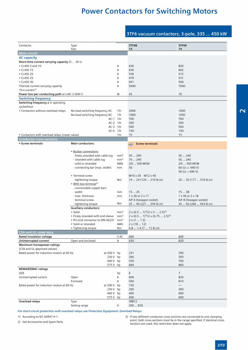
3TF6 vacuum contactors, 3-pole, 335 ... 450 kW3TF6 vacuum contactors, 3-pole, 335 ... 450 kW
Contactor TypeSize
3TF6814
3TF6914
Main circuitAC capacityShort-time current carrying capacity (5 ... 30 s)• CLASS 5 and 10• CLASS 15• CLASS 20• CLASS 25• CLASS 30
AAAAA
630630536479441
820662572531500
Thermal current-carrying capacity 10-s-current1)
A 5040 7000
Power loss per conducting path at Ie/AC-3 /690 V W 45 70
Switching frequencySwitching frequency z in operating cycles/hour• Contactors without overload relays No-load switching frequency AC 1/h 2000 1000
No-load switching frequency DCAC-1AC-2AC-3AC-4
1/h1/h1/h1/h1/h
1000700200500150
1000700200500150
• Contactors with overload relays (mean value) 1/h 15 15
Conductor cross-sections• Screw terminals Main conductors: Screw terminals
• Busbar connections - finely stranded with cable lug - stranded with cable lug - solid or stranded - connecting bar (max. width)
mm2
mm2
AWGmm
50 ... 24070 ... 240 2/0 ... 500 MCM50
50 ... 240 50 ... 240 2/0 ... 500 MCM60 (Ue ≤ 690 V) 50 (Ue > 690 V)
• Terminal screw M10 x 30 M12 x 40 - tightening torque Nm 14 ... 24 (124 ... 210 lb.in) 20 ... 35 (177 ... 310 lb.in)• With box terminal2)
- connectable copper bars - width - max. thickness - terminal screw - tightening torque
mmmm Nm
15 ... 251 x 26 or 2 x 11A/F 6 (hexagon socket)25 ... 40 (221 ... 354 lb.in)
15 ... 381 x 46 or 2 x 18A/F 8 (hexagon socket)35 ... 50 (266 ... 443 lb.in)
Auxiliary conductors:• Solid• Finely stranded with end sleeve• Pin-end connector to DIN 46231• Solid or stranded• Tightening torque
mm2
mm2
mm2
AWGNm
2 x (0.5 ... 1)3)/2 x (1 ... 2.5)3) 2 x (0.5 ... 1)3)/2 x (0.75 ... 2.5)3)
2 x (1 ... 1.5) 2 x (18 ... 12) 0.8 ... 1.4 (7 ... 12 lb.in)
CSA and UL rated data Rated insulation voltage V AC 600 600Uninterrupted current Open and enclosed A 630 820 Maximum horsepower ratings (CSA and UL approved values)Rated power for induction motors at 60 Hz at 200 V
230 V460 V575 V
hphphphp
231266530664
290350700860
NEMA/EEMAC ratingsSIZE hp 6 7Uninterrupted current Open
EnclosedAA
600540
820810
Rated power for induction motors at 60 Hz at 200 V230 V460 V575 V
hphphphp
150200400400
—300600600
Overload relays Type 3RB12 Setting range A 200 ... 820
For short-circuit protection with overload relays see Protection Equipment: Overload Relays.
1) According to IEC 60947-4-1.
2) See Accessories and Spare Parts.
3) If two different conductor cross-sections are connected to one clamping point, both cross-sections must lie in the range specified. If identical cross-sections are used, this restriction does not apply.
Power Contactors for Switching Motors
2/59
2
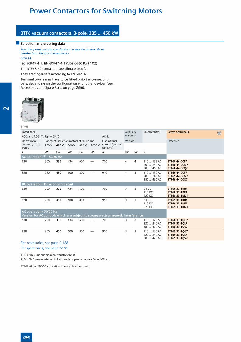
3TF6 vacuum contactors, 3-pole, 335 ... 450 kW 3TF6 vacuum contactors, 3-pole, 335 ... 450 kW
Selection and ordering data
Auxiliary and control conductors: screw terminals Main conductors: busbar connections
Size 14
IEC 60947-4-1, EN 60947-4-1 (VDE 0660 Part 102)
The 3TF68/69 contactors are climate-proof.
They are finger-safe according to EN 50274.
Terminal covers may have to be fitted onto the connecting bars, depending on the configuration with other devices (see Accessories and Spare Parts on page 2/56).
3TF68
Rated data Auxiliary contacts
Rated control Screw terminals
AC-2 and AC-3, Tu: Up to 55 °C AC-1,
Operational current Ie up to690 V
Rating of induction motors at 50 Hz and Operational current Ie up to (at 40°C)
Version Order No.
230 V 415 V 500 V 690 V 1000 V
A kW kW kW kW kW A NO NC V
AC operation1) 2) · 50/60 Hz630 200 335 434 600 — 700 4 4 110 … 132 AC
200 … 240 AC380 … 460 AC
3TF68 44-0CF73TF68 44-0CM73TF68 44-0CQ7
820 260 450 600 800 — 910 4 4 110 … 132 AC200 … 240 AC380 … 460 AC
3TF69 44-0CF73TF69 44-0CM73TF69 44-0CQ7
DC operation · DC economy circuit630 200 335 434 600 — 700 3 3 24 DC
110 DC220 DC
3TF68 33-1DB43TF68 33-1DF43TF68 33-1DM4
820 260 450 600 800 — 910 3 3 24 DC110 DC220 DC
3TF69 33-1DB43TF69 33-1DF43TF69 33-1DM4
AC operation · 50/60 Hz · Version for AC controls which are subject to strong electromagnetic interference630 200 335 434 600 — 700 3 3 110 ... 120 AC
220 ... 240 AC380 ... 420 AC
3TF68 33-1QG73TF68 33-1QL73TF68 33-1QV7
820 260 450 600 800 — 910 3 3 110 ... 120 AC220 ... 240 AC380 ... 420 AC
3TF69 33-1QG73TF69 33-1QL73TF69 33-1QV7
For accessories, see page 2/188
For spare parts, see page 2/191
1) Built-in surge suppression: varistor circuit.
2) For EMC please refer technical details or please contact Sales Office.
3TF68/69 for 1000V application is available on request.
Power Contactors for Switching Motors
2/60
2
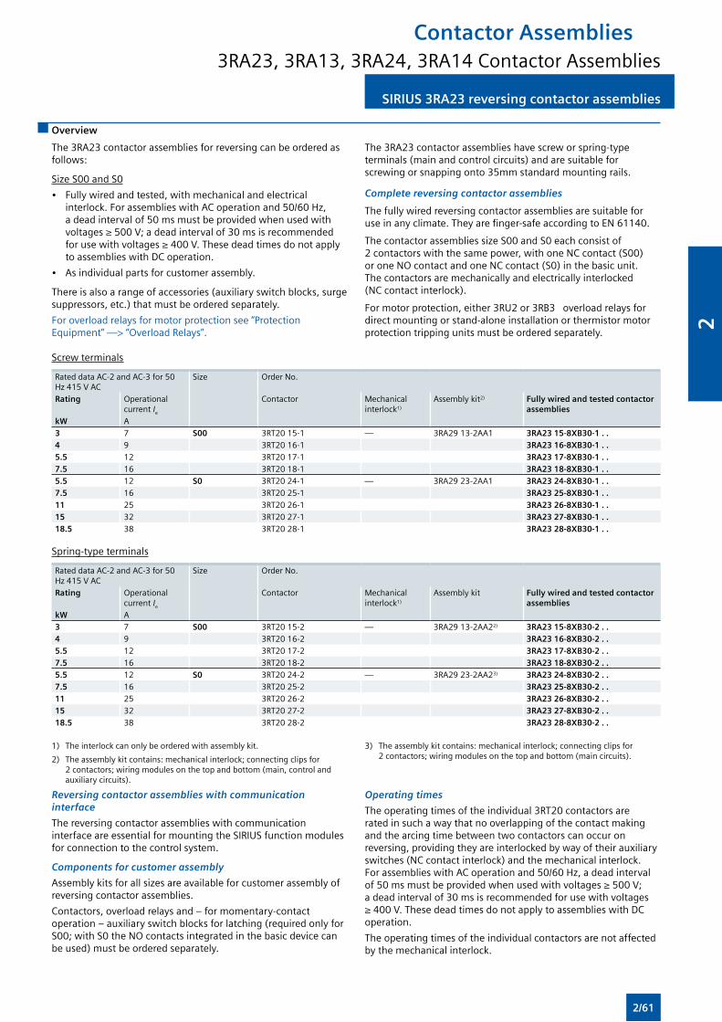
Overview
SIRIUS 3RA23 reversing contactor assembliesSIRIUS 3RA23 reversing contactor assemblies
The 3RA23 contactor assemblies for reversing can be ordered as follows:
Size S00 and S0
• Fully wired and tested, with mechanical and electrical interlock. For assemblies with AC operation and 50/60 Hz, a dead interval of 50 ms must be provided when used with voltages ≥ 500 V; a dead interval of 30 ms is recommended for use with voltages ≥ 400 V. These dead times do not apply to assemblies with DC operation.
• As individual parts for customer assembly.
There is also a range of accessories (auxiliary switch blocks, surge suppressors, etc.) that must be ordered separately.
For overload relays for motor protection see “Protection Equipment” —> “Overload Relays”.
The 3RA23 contactor assemblies have screw or spring-type terminals (main and control circuits) and are suitable for screwing or snapping onto 35mm standard mounting rails.
Complete reversing contactor assemblies
The fully wired reversing contactor assemblies are suitable for use in any climate. They are finger-safe according to EN 61140.
The contactor assemblies size S00 and S0 each consist of 2 contactors with the same power, with one NC contact (S00) or one NO contact and one NC contact (S0) in the basic unit. The contactors are mechanically and electrically interlocked (NC contact interlock).
For motor protection, either 3RU2 or 3RB3 overload relays for direct mounting or stand-alone installation or thermistor motor protection tripping units must be ordered separately.
Screw terminals
Rated data AC-2 and AC-3 for 50 Hz 415 V AC
Size Order No.
Rating Operational current Ie
Contactor Mechanical interlock1)
Assembly kit2) Fully wired and tested contactor assemblies
kW A3 7 S00 3RT20 15-1 — 3RA29 13-2AA1 3RA23 15-8XB30-1 . .4 9 3RT20 16-1 3RA23 16-8XB30-1 . .5.5 12 3RT20 17-1 3RA23 17-8XB30-1 . .7.5 16 3RT20 18-1 3RA23 18-8XB30-1 . .5.5 12 S0 3RT20 24-1 — 3RA29 23-2AA1 3RA23 24-8XB30-1 . .7.5 16 3RT20 25-1 3RA23 25-8XB30-1 . .11 25 3RT20 26-1 3RA23 26-8XB30-1 . .15 32 3RT20 27-1 3RA23 27-8XB30-1 . .18.5 38 3RT20 28-1 3RA23 28-8XB30-1 . .
Spring-type terminals
Rated data AC-2 and AC-3 for 50 Hz 415 V AC
Size Order No.
Rating Operational current Ie
Contactor Mechanical interlock1)
Assembly kit Fully wired and tested contactor assemblies
kW A3 7 S00 3RT20 15-2 — 3RA29 13-2AA22) 3RA23 15-8XB30-2 . .4 9 3RT20 16-2 3RA23 16-8XB30-2 . .5.5 12 3RT20 17-2 3RA23 17-8XB30-2 . .7.5 16 3RT20 18-2 3RA23 18-8XB30-2 . .5.5 12 S0 3RT20 24-2 — 3RA29 23-2AA23) 3RA23 24-8XB30-2 . .7.5 16 3RT20 25-2 3RA23 25-8XB30-2 . .11 25 3RT20 26-2 3RA23 26-8XB30-2 . .15 32 3RT20 27-2 3RA23 27-8XB30-2 . .18.5 38 3RT20 28-2 3RA23 28-8XB30-2 . .
1) The interlock can only be ordered with assembly kit.
2) The assembly kit contains: mechanical interlock; connecting clips for 2 contactors; wiring modules on the top and bottom (main, control and auxiliary circuits).
3) The assembly kit contains: mechanical interlock; connecting clips for 2 contactors; wiring modules on the top and bottom (main circuits).
Reversing contactor assemblies with communication interface
The reversing contactor assemblies with communication interface are essential for mounting the SIRIUS function modules for connection to the control system.
Components for customer assembly
Assembly kits for all sizes are available for customer assembly of reversing contactor assemblies.
Contactors, overload relays and – for momentary-contact operation – auxiliary switch blocks for latching (required only for S00; with S0 the NO contacts integrated in the basic device can be used) must be ordered separately.
Operating times
The operating times of the individual 3RT20 contactors are rated in such a way that no overlapping of the contact making and the arcing time between two contactors can occur on reversing, providing they are interlocked by way of their auxiliary switches (NC contact interlock) and the mechanical interlock. For assemblies with AC operation and 50/60 Hz, a dead interval of 50 ms must be provided when used with voltages ≥ 500 V; a dead interval of 30 ms is recommended for use with voltages ≥ 400 V. These dead times do not apply to assemblies with DC operation.
The operating times of the individual contactors are not affected by the mechanical interlock.
Contactor Assemblies3RA23, 3RA13, 3RA24, 3RA14 Contactor Assemblies
2/61
2
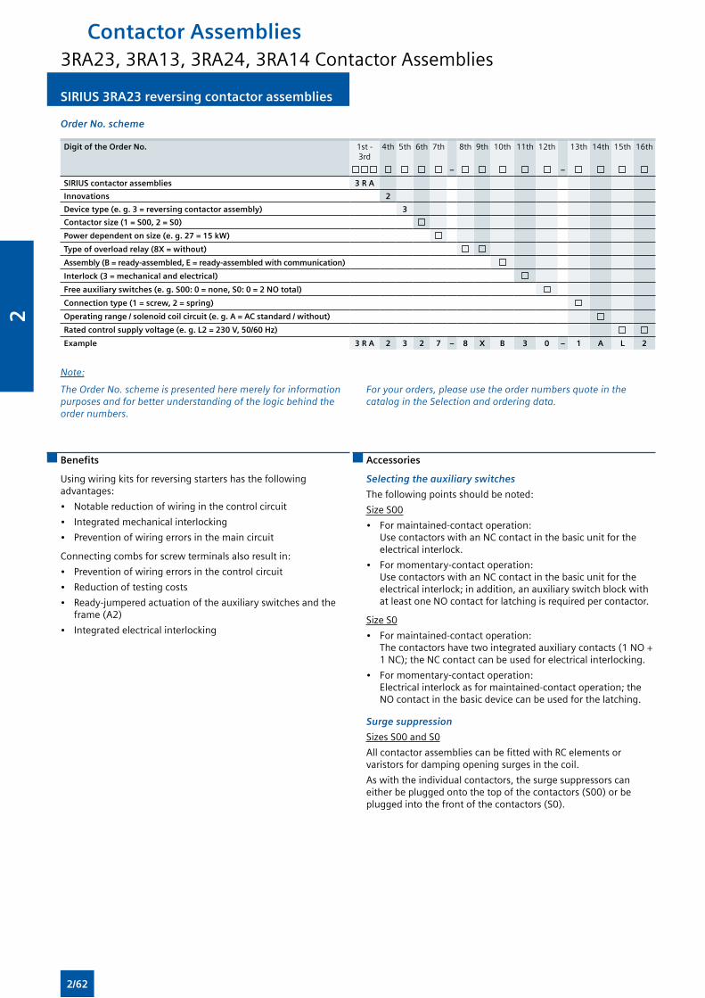
SIRIUS 3RA23 reversing contactor assemblies SIRIUS 3RA23 reversing contactor assemblies
Order No. scheme
Digit of the Order No. 1st - 3rd
4th 5th 6th 7th 8th 9th 10th 11th 12th 13th 14th 15th 16th
– –
SIRIUS contactor assemblies 3 R A
Innovations 2
Device type (e. g. 3 = reversing contactor assembly) 3
Contactor size (1 = S00, 2 = S0)
Power dependent on size (e. g. 27 = 15 kW)
Type of overload relay (8X = without)
Assembly (B = ready-assembled, E = ready-assembled with communication)
Interlock (3 = mechanical and electrical)
Free auxiliary switches (e. g. S00: 0 = none, S0: 0 = 2 NO total)
Connection type (1 = screw, 2 = spring)
Operating range / solenoid coil circuit (e. g. A = AC standard / without)
Rated control supply voltage (e. g. L2 = 230 V, 50/60 Hz)
Example 3 R A 2 3 2 7 – 8 X B 3 0 – 1 A L 2
Note:
The Order No. scheme is presented here merely for information purposes and for better understanding of the logic behind the order numbers.
For your orders, please use the order numbers quote in the catalog in the Selection and ordering data.
Benefits
Using wiring kits for reversing starters has the following advantages:
• Notable reduction of wiring in the control circuit
• Integrated mechanical interlocking
• Prevention of wiring errors in the main circuit
Connecting combs for screw terminals also result in:
• Prevention of wiring errors in the control circuit
• Reduction of testing costs
• Ready-jumpered actuation of the auxiliary switches and the frame (A2)
• Integrated electrical interlocking
Accessories
Selecting the auxiliary switches
The following points should be noted:
Size S00
• For maintained-contact operation: Use contactors with an NC contact in the basic unit for the electrical interlock.
• For momentary-contact operation: Use contactors with an NC contact in the basic unit for the electrical interlock; in addition, an auxiliary switch block with at least one NO contact for latching is required per contactor.
Size S0
• For maintained-contact operation: The contactors have two integrated auxiliary contacts (1 NO + 1 NC); the NC contact can be used for electrical interlocking.
• For momentary-contact operation: Electrical interlock as for maintained-contact operation; the NO contact in the basic device can be used for the latching.
Surge suppression
Sizes S00 and S0
All contactor assemblies can be fitted with RC elements or varistors for damping opening surges in the coil.
As with the individual contactors, the surge suppressors can either be plugged onto the top of the contactors (S00) or be plugged into the front of the contactors (S0).
Contactor Assemblies3RA23, 3RA13, 3RA24, 3RA14 Contactor Assemblies
2/62
2
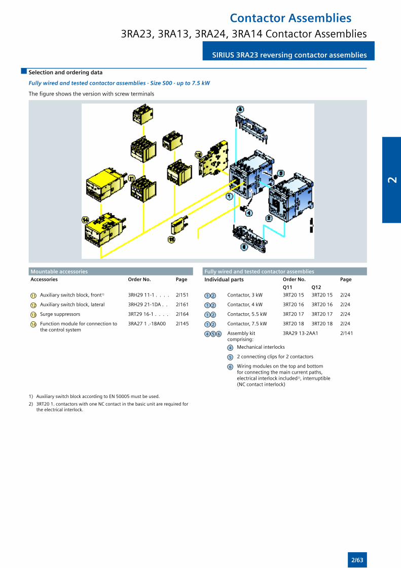
SIRIUS 3RA23 reversing contactor assembliesSIRIUS 3RA23 reversing contactor assemblies
Selection and ordering data
Fully wired and tested contactor assemblies · Size S00 · up to 7.5 kW
The figure shows the version with screw terminals
Mountable accessories Fully wired and tested contactor assembliesAccessories Order No. Page Individual parts Order No. Page
Q11 Q12
11 Auxiliary switch block, front1) 3RH29 11-1 . . . . 2/151 1 2 Contactor, 3 kW 3RT20 15 3RT20 15 2/24
12 Auxiliary switch block, lateral 3RH29 21-1DA . . 2/161 1 2 Contactor, 4 kW 3RT20 16 3RT20 16 2/24
13 Surge suppressors 3RT29 16-1 . . . . 2/164 1 2 Contactor, 5.5 kW 3RT20 17 3RT20 17 2/24
14 Function module for connection to the control system
3RA27 1 .-1BA00 2/145 1 2 Contactor, 7.5 kW 3RT20 18 3RT20 18 2/24
4 5 6 Assembly kit comprising:
3RA29 13-2AA1 2/141
4 Mechanical interlocks
5 2 connecting clips for 2 contactors
6 Wiring modules on the top and bottom for connecting the main current paths, electrical interlock included2), interruptible (NC contact interlock)
1) Auxiliary switch block according to EN 50005 must be used.
2) 3RT20 1. contactors with one NC contact in the basic unit are required for the electrical interlock.
Contactor Assemblies3RA23, 3RA13, 3RA24, 3RA14 Contactor Assemblies
2/63
2
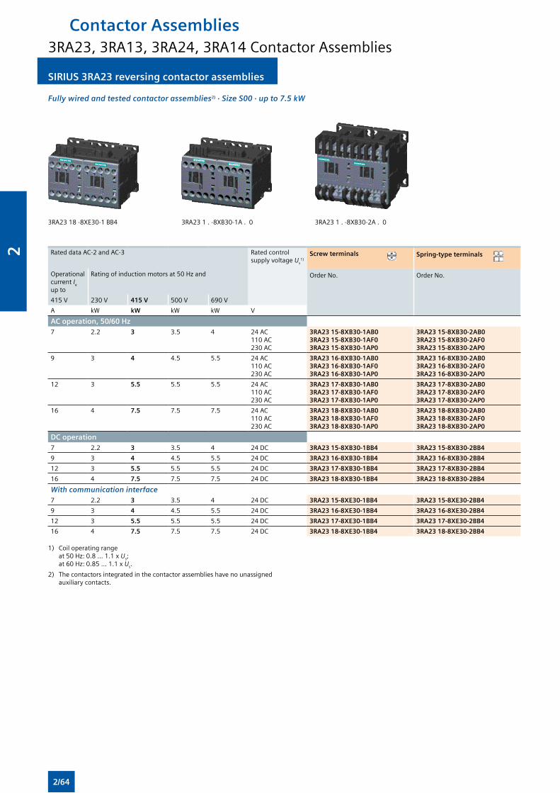
SIRIUS 3RA23 reversing contactor assemblies SIRIUS 3RA23 reversing contactor assemblies
Fully wired and tested contactor assemblies2) · Size S00 · up to 7.5 kW
3RA23 18 -8XE30-1 BB4 3RA23 1 . -8XB30-1A . 0 3RA23 1 . -8XB30-2A . 0
Rated data AC-2 and AC-3 Rated control supply voltage Us
1)Screw terminals Spring-type terminals
Operational current Ie
up to
Rating of induction motors at 50 Hz and Order No. Order No.
415 V 230 V 415 V 500 V 690 V
A kW kW kW kW V
AC operation, 50/60 Hz7 2.2 3 3.5 4 24 AC
110 AC230 AC
3RA23 15-8XB30-1AB03RA23 15-8XB30-1AF03RA23 15-8XB30-1AP0
3RA23 15-8XB30-2AB03RA23 15-8XB30-2AF03RA23 15-8XB30-2AP0
9 3 4 4.5 5.5 24 AC110 AC230 AC
3RA23 16-8XB30-1AB03RA23 16-8XB30-1AF03RA23 16-8XB30-1AP0
3RA23 16-8XB30-2AB03RA23 16-8XB30-2AF03RA23 16-8XB30-2AP0
12 3 5.5 5.5 5.5 24 AC110 AC230 AC
3RA23 17-8XB30-1AB03RA23 17-8XB30-1AF03RA23 17-8XB30-1AP0
3RA23 17-8XB30-2AB03RA23 17-8XB30-2AF03RA23 17-8XB30-2AP0
16 4 7.5 7.5 7.5 24 AC110 AC230 AC
3RA23 18-8XB30-1AB03RA23 18-8XB30-1AF03RA23 18-8XB30-1AP0
3RA23 18-8XB30-2AB03RA23 18-8XB30-2AF03RA23 18-8XB30-2AP0
DC operation 7 2.2 3 3.5 4 24 DC 3RA23 15-8XB30-1BB4 3RA23 15-8XB30-2BB4
9 3 4 4.5 5.5 24 DC 3RA23 16-8XB30-1BB4 3RA23 16-8XB30-2BB4
12 3 5.5 5.5 5.5 24 DC 3RA23 17-8XB30-1BB4 3RA23 17-8XB30-2BB4
16 4 7.5 7.5 7.5 24 DC 3RA23 18-8XB30-1BB4 3RA23 18-8XB30-2BB4
With communication interface7 2.2 3 3.5 4 24 DC 3RA23 15-8XE30-1BB4 3RA23 15-8XE30-2BB4
9 3 4 4.5 5.5 24 DC 3RA23 16-8XE30-1BB4 3RA23 16-8XE30-2BB4
12 3 5.5 5.5 5.5 24 DC 3RA23 17-8XE30-1BB4 3RA23 17-8XE30-2BB4
16 4 7.5 7.5 7.5 24 DC 3RA23 18-8XE30-1BB4 3RA23 18-8XE30-2BB4
1) Coil operating range at 50 Hz: 0.8 ... 1.1 x Us; at 60 Hz: 0.85 ... 1.1 x Us.
2) The contactors integrated in the contactor assemblies have no unassigned auxiliary contacts.
Contactor Assemblies3RA23, 3RA13, 3RA24, 3RA14 Contactor Assemblies
2/64
2
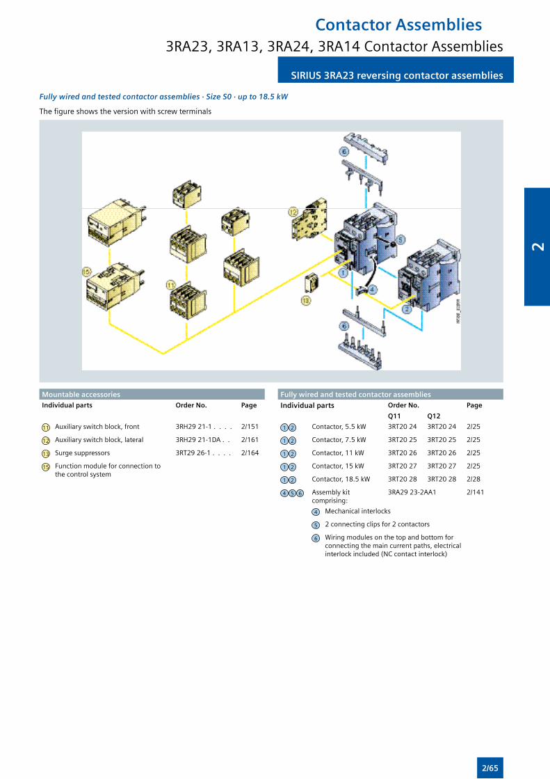
SIRIUS 3RA23 reversing contactor assembliesSIRIUS 3RA23 reversing contactor assemblies
Fully wired and tested contactor assemblies · Size S0 · up to 18.5 kW
The figure shows the version with screw terminals
Mountable accessories Fully wired and tested contactor assembliesIndividual parts Order No. Page Individual parts Order No. Page
Q11 Q12
11 Auxiliary switch block, front 3RH29 21-1 . . . . 2/151 1 2 Contactor, 5.5 kW 3RT20 24 3RT20 24 2/25
12 Auxiliary switch block, lateral 3RH29 21-1DA . . 2/161 1 2 Contactor, 7.5 kW 3RT20 25 3RT20 25 2/25
13 Surge suppressors 3RT29 26-1 . . . . 2/164 1 2 Contactor, 11 kW 3RT20 26 3RT20 26 2/25
15 Function module for connection to the control system
1 2 Contactor, 15 kW 3RT20 27 3RT20 27 2/25
1 2 Contactor, 18.5 kW 3RT20 28 3RT20 28 2/28
4 5 6 Assembly kit comprising:
3RA29 23-2AA1 2/141
4 Mechanical interlocks
5 2 connecting clips for 2 contactors
6 Wiring modules on the top and bottom for connecting the main current paths, electrical interlock included (NC contact interlock)
Contactor Assemblies3RA23, 3RA13, 3RA24, 3RA14 Contactor Assemblies
2/65
2
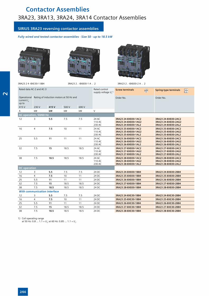
SIRIUS 3RA23 reversing contactor assemblies SIRIUS 3RA23 reversing contactor assemblies
Fully wired and tested contactor assemblies · Size S0 · up to 18.5 kW
3RA23 2 4 -8XE30-1 BB4 3RA23 2 . -8XB30-1 A . 2 3RA23 2 . -8XB30-2 A . 2
Rated data AC-2 and AC-3 Rated control supply voltage Us
1)Screw terminals Spring-type terminals
Operational current Ie
up to
Rating of induction motors at 50 Hz and Order No. Order No.
415 V 230 V 415 V 500 V 690 V
A kW kW kW kW V
AC operation, 50/60 Hz12 3 5.5 7.5 7.5 24 AC
110 AC230 AC
3RA23 24-8XB30-1AC23RA23 24-8XB30-1AG23RA23 24-8XB30-1AL2
3RA23 24-8XB30-2AC23RA23 24-8XB30-2AG23RA23 24-8XB30-2AL2
16 4 7.5 10 11 24 AC110 AC230 AC
3RA23 25-8XB30-1AC23RA23 25-8XB30-1AG23RA23 25-8XB30-1AL2
3RA23 25-8XB30-2AC23RA23 25-8XB30-2AG23RA23 25-8XB30-2AL2
25 5.5 11 11 11 24 AC110 AC230 AC
3RA23 26-8XB30-1AC23RA23 26-8XB30-1AG23RA23 26-8XB30-1AL2
3RA23 26-8XB30-2AC23RA23 26-8XB30-2AG23RA23 26-8XB30-2AL2
32 7.5 15 18.5 18.5 24 AC110 AC230 AC
3RA23 27-8XB30-1AC23RA23 27-8XB30-1AG23RA23 27-8XB30-1AL2
3RA23 27-8XB30-2AC23RA23 27-8XB30-2AG23RA23 27-8XB30-2AL2
38 7.5 18.5 18.5 18.5 24 AC110 AC230 AC
3RA23 28-8XB30-1AC23RA23 28-8XB30-1AG23RA23 28-8XB30-1AL2
3RA23 28-8XB30-2AC23RA23 28-8XB30-2AG23RA23 28-8XB30-2AL2
DC operation12 3 5.5 7.5 7.5 24 DC 3RA23 24-8XB30-1BB4 3RA23 24-8XB30-2BB4
16 4 7.5 10 11 24 DC 3RA23 25-8XB30-1BB4 3RA23 25-8XB30-2BB4
25 5.5 11 11 11 24 DC 3RA23 26-8XB30-1BB4 3RA23 26-8XB30-2BB4
32 7.5 15 18.5 18.5 24 DC 3RA23 27-8XB30-1BB4 3RA23 27-8XB30-2BB4
38 7.5 18.5 18.5 18.5 24 DC 3RA23 28-8XB30-1BB4 3RA23 28-8XB30-2BB4
With communication interface12 3 5.5 7.5 7.5 24 DC 3RA23 24-8XE30-1BB4 3RA23 24-8XE30-2BB4
16 4 7.5 10 11 24 DC 3RA23 25-8XE30-1BB4 3RA23 25-8XE30-2BB4
25 5.5 11 11 11 24 DC 3RA23 26-8XE30-1BB4 3RA23 26-8XE30-2BB4
32 7.5 15 18.5 18.5 24 DC 3RA23 27-8XE30-1BB4 3RA23 27-8XE30-2BB4
38 7.5 18.5 18.5 18.5 24 DC 3RA23 28-8XE30-1BB4 3RA23 28-8XE30-2BB4
1) Coil operating range at 50 Hz: 0.8 ... 1.1 × Us; at 60 Hz: 0.85 ... 1.1 × Us.
Contactor Assemblies3RA23, 3RA13, 3RA24, 3RA14 Contactor Assemblies
2/66
2
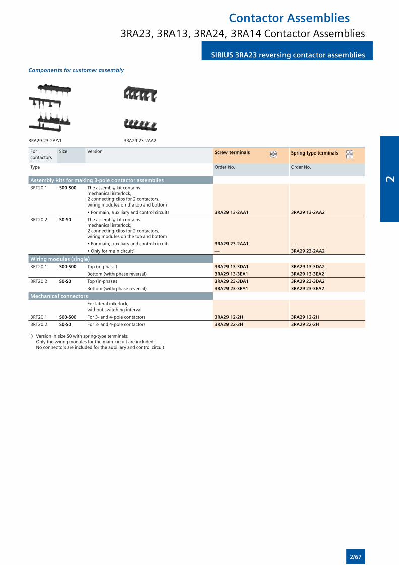
SIRIUS 3RA23 reversing contactor assembliesSIRIUS 3RA23 reversing contactor assemblies
Components for customer assembly
3RA29 23-2AA1 3RA29 23-2AA2
For contactors
Size Version Screw terminals Spring-type terminals
Type Order No. Order No.
Assembly kits for making 3-pole contactor assemblies 3RT20 1 S00-S00 The assembly kit contains:
mechanical interlock; 2 connecting clips for 2 contactors, wiring modules on the top and bottom
• For main, auxiliary and control circuits 3RA29 13-2AA1 3RA29 13-2AA2
3RT20 2 S0-S0 The assembly kit contains: mechanical interlock; 2 connecting clips for 2 contactors, wiring modules on the top and bottom
• For main, auxiliary and control circuits 3RA29 23-2AA1 —
• Only for main circuit1) — 3RA29 23-2AA2
Wiring modules (single) 3RT20 1 S00-S00 Top (in-phase) 3RA29 13-3DA1 3RA29 13-3DA2
Bottom (with phase reversal) 3RA29 13-3EA1 3RA29 13-3EA2
3RT20 2 S0-S0 Top (in-phase) 3RA29 23-3DA1 3RA29 23-3DA2
Bottom (with phase reversal) 3RA29 23-3EA1 3RA29 23-3EA2
Mechanical connectors For lateral interlock, without switching interval
3RT20 1 S00-S00 For 3- and 4-pole contactors 3RA29 12-2H 3RA29 12-2H
3RT20 2 S0-S0 For 3- and 4-pole contactors 3RA29 22-2H 3RA29 22-2H
1) Version in size S0 with spring-type terminals: Only the wiring modules for the main circuit are included. No connectors are included for the auxiliary and control circuit.
Contactor Assemblies3RA23, 3RA13, 3RA24, 3RA14 Contactor Assemblies
2/67
2
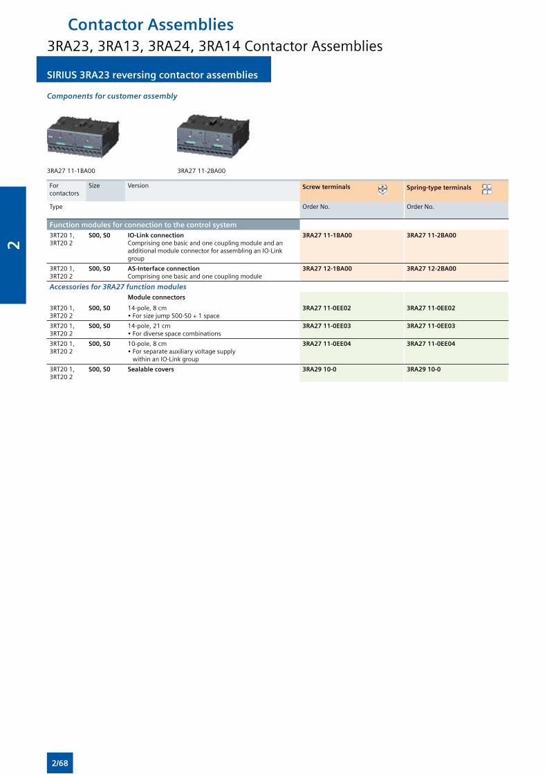
SIRIUS 3RA23 reversing contactor assemblies SIRIUS 3RA23 reversing contactor assemblies
Components for customer assembly
3RA27 11-1BA00 3RA27 11-2BA00
For contactors
Size Version Screw terminals Spring-type terminals
Type Order No. Order No.
Function modules for connection to the control system3RT20 1, 3RT20 2
S00, S0 IO-Link connectionComprising one basic and one coupling module and an additional module connector for assembling an IO-Link group
3RA27 11-1BA00 3RA27 11-2BA00
3RT20 1, 3RT20 2
S00, S0 AS-Interface connection Comprising one basic and one coupling module
3RA27 12-1BA00 3RA27 12-2BA00
Accessories for 3RA27 function modulesModule connectors
3RT20 1, 3RT20 2
S00, S0 14-pole, 8 cm• For size jump S00-S0 + 1 space
3RA27 11-0EE02 3RA27 11-0EE02
3RT20 1, 3RT20 2
S00, S0 14-pole, 21 cm• For diverse space combinations
3RA27 11-0EE03 3RA27 11-0EE03
3RT20 1, 3RT20 2
S00, S0 10-pole, 8 cm• For separate auxiliary voltage supply within an IO-Link group
3RA27 11-0EE04 3RA27 11-0EE04
3RT20 1, 3RT20 2
S00, S0 Sealable covers 3RA29 10-0 3RA29 10-0
Contactor Assemblies3RA23, 3RA13, 3RA24, 3RA14 Contactor Assemblies
2/68
2
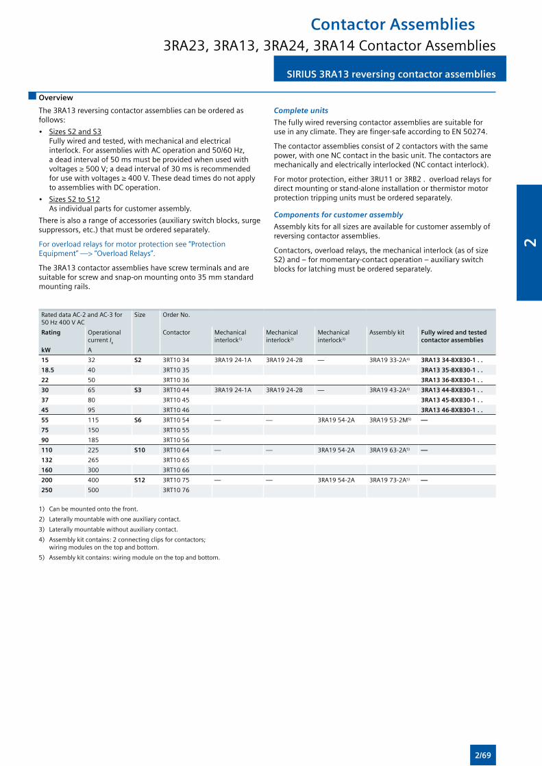
SIRIUS 3RA13 reversing contactor assembliesSIRIUS 3RA13 reversing contactor assemblies
Overview
The 3RA13 reversing contactor assemblies can be ordered as follows:
• Sizes S2 and S3 Fully wired and tested, with mechanical and electrical interlock. For assemblies with AC operation and 50/60 Hz, a dead interval of 50 ms must be provided when used with voltages ≥ 500 V; a dead interval of 30 ms is recommended for use with voltages ≥ 400 V. These dead times do not apply to assemblies with DC operation.
• Sizes S2 to S12 As individual parts for customer assembly.
There is also a range of accessories (auxiliary switch blocks, surge suppressors, etc.) that must be ordered separately.
For overload relays for motor protection see “Protection Equipment” —> “Overload Relays”.
The 3RA13 contactor assemblies have screw terminals and are suitable for screw and snap-on mounting onto 35 mm standard mounting rails.
Complete units
The fully wired reversing contactor assemblies are suitable for use in any climate. They are finger-safe according to EN 50274.
The contactor assemblies consist of 2 contactors with the same power, with one NC contact in the basic unit. The contactors are mechanically and electrically interlocked (NC contact interlock).
For motor protection, either 3RU11 or 3RB2 . overload relays for direct mounting or stand-alone installation or thermistor motor protection tripping units must be ordered separately.
Components for customer assembly
Assembly kits for all sizes are available for customer assembly of reversing contactor assemblies.
Contactors, overload relays, the mechanical interlock (as of size S2) and – for momentary-contact operation – auxiliary switch blocks for latching must be ordered separately.
Rated data AC-2 and AC-3 for 50 Hz 400 V AC
Size Order No.
Rating Operational current Ie
Contactor Mechanical interlock1)
Mechanical interlock2)
Mechanical interlock3)
Assembly kit Fully wired and tested contactor assemblies
kW A
15 32 S2 3RT10 34 3RA19 24-1A 3RA19 24-2B — 3RA19 33-2A4) 3RA13 34-8XB30-1 . .
18.5 40 3RT10 35 3RA13 35-8XB30-1 . .
22 50 3RT10 36 3RA13 36-8XB30-1 . .
30 65 S3 3RT10 44 3RA19 24-1A 3RA19 24-2B — 3RA19 43-2A4) 3RA13 44-8XB30-1 . .
37 80 3RT10 45 3RA13 45-8XB30-1 . .
45 95 3RT10 46 3RA13 46-8XB30-1 . .
55 115 S6 3RT10 54 — — 3RA19 54-2A 3RA19 53-2M5) —
75 150 3RT10 55
90 185 3RT10 56
110 225 S10 3RT10 64 — — 3RA19 54-2A 3RA19 63-2A5) —
132 265 3RT10 65
160 300 3RT10 66
200 400 S12 3RT10 75 — — 3RA19 54-2A 3RA19 73-2A5) —
250 500 3RT10 76
1) Can be mounted onto the front.
2) Laterally mountable with one auxiliary contact.
3) Laterally mountable without auxiliary contact.
4) Assembly kit contains: 2 connecting clips for contactors; wiring modules on the top and bottom.
5) Assembly kit contains: wiring module on the top and bottom.
Contactor Assemblies3RA23, 3RA13, 3RA24, 3RA14 Contactor Assemblies
2/69
2
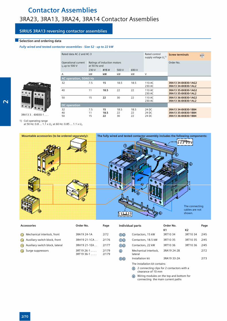
SIRIUS 3RA13 reversing contactor assemblies SIRIUS 3RA13 reversing contactor assemblies
Selection and ordering data
Fully wired and tested contactor assemblies · Size S2 · up to 22 kW
Rated data AC-2 and AC-3 Rated control supply voltage Us
1)Screw terminals
Operational current Ie up to 500 V
Ratings of induction motors at 50 Hz and
Order No.
230 V 415 V 500 V 690 V
A kW kW kW kW V
AC operation, 50/60 Hz
3RA13 3 . -8XB30-1 . . .
32 7.5 15 18.5 18.5 110 AC230 AC
3RA13 34-8XB30-1AG23RA13 34-8XB30-1AL2
40 11 18.5 22 22 110 AC230 AC
3RA13 35-8XB30-1AG23RA13 35-8XB30-1AL2
50 15 22 30 22 110 AC230 AC
3RA13 36-8XB30-1AG23RA13 36-8XB30-1AL2
DC operation324050
7.51115
15 18.5 22
18.52230
18.52222
24 DC24 DC24 DC
3RA13 34-8XB30-1BB43RA13 35-8XB30-1BB43RA13 36-8XB30-1BB4
1) Coil operating range at 50 Hz: 0.8 ... 1.1 x Us; at 60 Hz: 0.85 ... 1.1 x Us.
Accessories Order No. Page Individual parts Order No. Page
K1 K2
12 Mechanical interlock, front 3RA19 24-1A 2/72 1 2 Contactors, 15 kW 3RT10 34 3RT10 34 2/45
14 Auxiliary switch block, front 3RH19 21-1CA . . 2/176 1 2 Contactors, 18.5 kW 3RT10 35 3RT10 35 2/45
15 Auxiliary switch block, lateral 3RH19 21-1EA . . 2/177 1 2 Contactors, 22 kW 3RT10 36 3RT10 36 2/45
16 Surge suppressors 3RT19 26-1 . . . . 3RT19 36-1 . . . .
2/1792/179
4 Mechanical interlock, lateral
3RA19 24-2B 2/72
5 6 Installation kit 3RA19 33-2A 2/73
The installation kit contains:
5 2 connecting clips for 2 contactors with a clearance of 10 mm
6 Wiring modules on the top and bottom for connecting the main current paths
Mountable accessories (to be ordered separately): The fully wired and tested contactor assembly includes the following components:
Contactor Assemblies3RA23, 3RA13, 3RA24, 3RA14 Contactor Assemblies
The connecting cables are not shown.
2/70
2
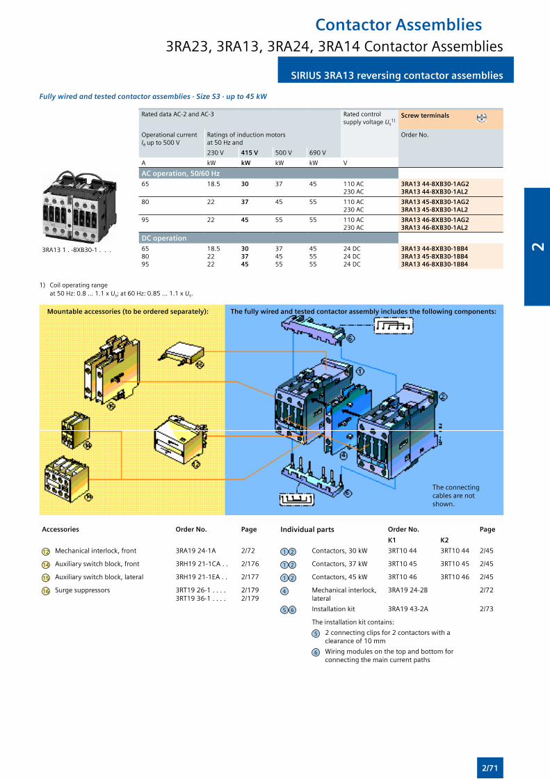
SIRIUS 3RA13 reversing contactor assembliesSIRIUS 3RA13 reversing contactor assemblies
Fully wired and tested contactor assemblies · Size S3 · up to 45 kW
Rated data AC-2 and AC-3 Rated control supply voltage Us
1)Screw terminals
Operational current Ie up to 500 V
Ratings of induction motors at 50 Hz and
Order No.
230 V 415 V 500 V 690 V
A kW kW kW kW V
3RA13 1 . -8XB30-1 . . .
AC operation, 50/60 Hz65 18.5 30 37 45 110 AC
230 AC3RA13 44-8XB30-1AG23RA13 44-8XB30-1AL2
80 22 37 45 55 110 AC230 AC
3RA13 45-8XB30-1AG23RA13 45-8XB30-1AL2
95 22 45 55 55 110 AC230 AC
3RA13 46-8XB30-1AG23RA13 46-8XB30-1AL2
DC operation658095
18.52222
30 37 45
374555
455555
24 DC24 DC24 DC
3RA13 44-8XB30-1BB43RA13 45-8XB30-1BB43RA13 46-8XB30-1BB4
1) Coil operating range at 50 Hz: 0.8 ... 1.1 x Us; at 60 Hz: 0.85 ... 1.1 x Us.
Accessories Order No. Page Individual parts Order No. Page
K1 K2
12 Mechanical interlock, front 3RA19 24-1A 2/72 1 2 Contactors, 30 kW 3RT10 44 3RT10 44 2/45
14 Auxiliary switch block, front 3RH19 21-1CA . . 2/176 1 2 Contactors, 37 kW 3RT10 45 3RT10 45 2/45
15 Auxiliary switch block, lateral 3RH19 21-1EA . . 2/177 1 2 Contactors, 45 kW 3RT10 46 3RT10 46 2/45
16 Surge suppressors 3RT19 26-1 . . . . 3RT19 36-1 . . . .
2/1792/179
4 Mechanical interlock, lateral
3RA19 24-2B 2/72
5 6 Installation kit 3RA19 43-2A 2/73
The installation kit contains:
5 2 connecting clips for 2 contactors with a clearance of 10 mm
6 Wiring modules on the top and bottom for connecting the main current paths
Mountable accessories (to be ordered separately): The fully wired and tested contactor assembly includes the following components:
Contactor Assemblies3RA23, 3RA13, 3RA24, 3RA14 Contactor Assemblies
The connecting cables are not shown.
2/71
2
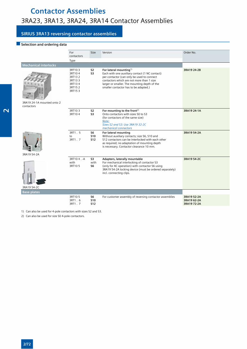
SIRIUS 3RA13 reversing contactor assemblies SIRIUS 3RA13 reversing contactor assemblies
Selection and ordering data
For contactors
Size Version Order No.
Type
Mechanical interlocks
3RA19 24-1A mounted onto 2 contactors
3RT10 3 3RT10 4 3RT13 2 3RT13 3 3RT13 4 3RT15 2 3RT15 3
S2 S3
For lateral mounting1) Each with one auxiliary contact (1 NC contact) per contactor (can only be used to connectcontactors which are not more than 1 size larger or smaller. The mounting depth of the smaller contactor has to be adapted.)
3RA19 24-2B
3RT10 3 3RT10 4
S2 S3
For mounting to the front2)
Onto contactors with sizes S0 to S3 (for contactors of the same size)Note: Sizes S2 and S3: Use 3RA19 32-2C mechanical connectors
3RA19 24-1A
3RA19 54-2A
3RT1 . 5 to 3RT1 . 7
S6 S10 S12
For lateral mounting Without auxiliary contacts; size S6, S10 andS12 contactors can be interlocked with each other as required; no adaptation of mounting depthis necessary. Contactor clearance 10 mm.
3RA19 54-2A
3RA19 54-2C
3RT10 4 . -Awith3RT10 5
S3 withS6
Adapters, laterally mountable For mechanical interlocking of contactor S3 (only for AC operation) with contactor S6 using 3RA19 54-2A locking device (must be ordered separately) incl. connecting clips.
3RA19 54-2C
Base plates 3RT10 5
3RT1 . 63RT1 . 7
S6 S10S12
For customer assembly of reversing contactor assemblies 3RA19 52-2A3RA19 62-2A3RA19 72-2A
1) Can also be used for 4-pole contactors with sizes S2 and S3.
2) Can also be used for size S0 4-pole contactors.
Contactor Assemblies3RA23, 3RA13, 3RA24, 3RA14 Contactor Assemblies
2/72
2
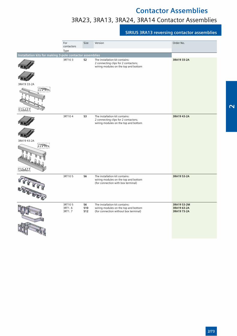
SIRIUS 3RA13 reversing contactor assembliesSIRIUS 3RA13 reversing contactor assemblies
For contactors
Size Version Order No.
Type
Installation kits for making 3-pole contactor assemblies
3RA19 33-2A
3RT10 3 S2 The installation kit contains: 2 connecting clips for 2 contactors; wiring modules on the top and bottom
3RA19 33-2A
3RA19 43-2A
3RT10 4 S3 The installation kit contains: 2 connecting clips for 2 contactors; wiring modules on the top and bottom
3RA19 43-2A
3RT10 5 S6 The installation kit contains: wiring modules on the top and bottom (for connection with box terminal)
3RA19 53-2A
3RT10 53RT1. 63RT1. 7
S6 S10S12
The installation kit contains: wiring modules on the top and bottom (for connection without box terminal)
3RA19 53-2M3RA19 63-2A3RA19 73-2A
Contactor Assemblies3RA23, 3RA13, 3RA24, 3RA14 Contactor Assemblies
2/73
2
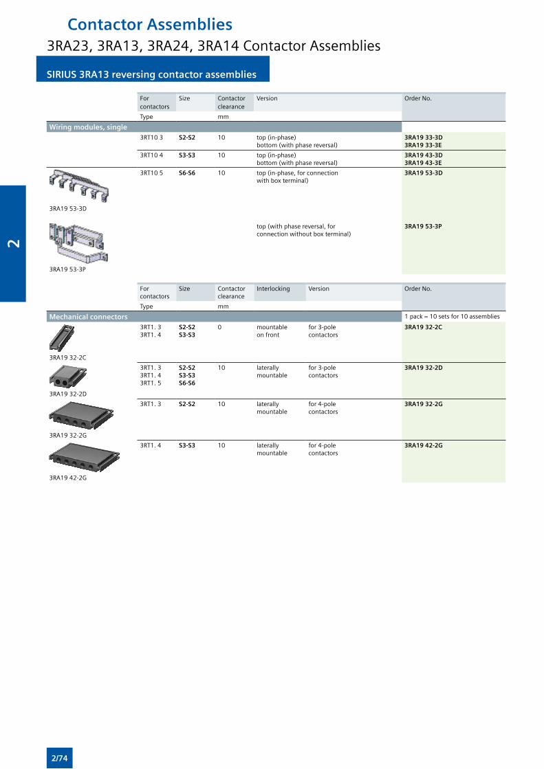
SIRIUS 3RA13 reversing contactor assemblies SIRIUS 3RA13 reversing contactor assemblies
For contactors
Size Contactor clearance
Version Order No.
Type mm
Wiring modules, single 3RT10 3 S2-S2 10 top (in-phase)
bottom (with phase reversal)3RA19 33-3D3RA19 33-3E
3RT10 4 S3-S3 10 top (in-phase)bottom (with phase reversal)
3RA19 43-3D3RA19 43-3E
3RA19 53-3D
3RT10 5 S6-S6 10 top (in-phase, for connection with box terminal)
3RA19 53-3D
3RA19 53-3P
top (with phase reversal, for connection without box terminal)
3RA19 53-3P
For contactors
Size Contactor clearance
Interlocking Version Order No.
Type mm
Mechanical connectors 1 pack = 10 sets for 10 assemblies
3RA19 32-2C
3RT1. 3 3RT1. 4
S2-S2 S3-S3
0 mountable on front
for 3-pole contactors
3RA19 32-2C
3RA19 32-2D
3RT1. 3 3RT1. 4 3RT1. 5
S2-S2 S3-S3 S6-S6
10 laterally mountable
for 3-pole contactors
3RA19 32-2D
3RA19 32-2G
3RT1. 3 S2-S2 10 laterally mountable
for 4-pole contactors
3RA19 32-2G
3RA19 42-2G
3RT1. 4 S3-S3 10 laterally mountable
for 4-pole contactors
3RA19 42-2G
Contactor Assemblies3RA23, 3RA13, 3RA24, 3RA14 Contactor Assemblies
2/74
2
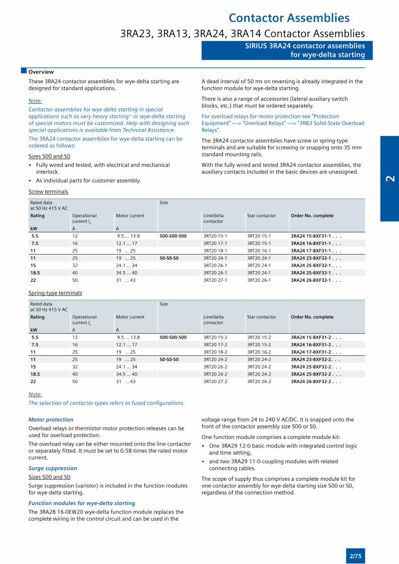
SIRIUS 3RA24 contactor assembliesfor wye-delta starting
SIRIUS 3RA24 contactor assembliesfor wye-delta starting
Overview
These 3RA24 contactor assemblies for wye-delta starting are designed for standard applications.
Note:
Contactor assemblies for wye-delta starting in special applications such as very heavy starting1) or wye-delta starting of special motors must be customized. Help with designing such special applications is available from Technical Assistance.
The 3RA24 contactor assemblies for wye-delta starting can be ordered as follows:
Sizes S00 and S0
• Fully wired and tested, with electrical and mechanical interlock.
• As individual parts for customer assembly.
A dead interval of 50 ms on reversing is already integrated in the function module for wye-delta starting.
There is also a range of accessories (lateral auxiliary switch blocks, etc.) that must be ordered separately.
For overload relays for motor protection see “Protection Equipment” —> “Overload Relays” —> “3RB3 Solid-State Overload Relays”.
The 3RA24 contactor assemblies have screw or spring-type terminals and are suitable for screwing or snapping onto 35 mm standard mounting rails.
With the fully wired and tested 3RA24 contactor assemblies, the auxiliary contacts included in the basic devices are unassigned.
Screw terminals
Rated dataat 50 Hz 415 V AC
Size
Rating Operational current Ie
Motor current Line/delta contactor
Star contactor Order No. complete
kW A A
5.5 12 9.5 ... 13.8 S00-S00-S00 3RT20 15-1 3RT20 15-1 3RA24 15-8XF31-1 . . .
7.5 16 12.1 ... 17 3RT20 17-1 3RT20 15-1 3RA24 16-8XF31-1 . . .
11 25 19 ... 25 3RT20 18-1 3RT20 16-1 3RA24 17-8XF31-1 . . .
11 25 19 ... 25 S0-S0-S0 3RT20 24-1 3RT20 24-1 3RA24 23-8XF32-1 . . .
15 32 24.1 ... 34 3RT20 26-1 3RT20 24-1 3RA24 25-8XF32-1 . . .
18.5 40 34.5 ... 40 3RT20 26-1 3RT20 24-1 3RA24 25-8XF32-1 . . .
22 50 31 ... 43 3RT20 27-1 3RT20 26-1 3RA24 26-8XF32-1 . . .
Spring-type terminals
Rated dataat 50 Hz 415 V AC
Size
Rating Operational current Ie
Motor current Line/delta contactor
Star contactor Order No. complete
kW A A
5.5 12 9.5 ... 13.8 S00-S00-S00 3RT20 15-2 3RT20 15-2 3RA24 15-8XF31-2 . . .
7.5 16 12.1 ... 17 3RT20 17-2 3RT20 15-2 3RA24 16-8XF31-2 . . .
11 25 19 ... 25 3RT20 18-2 3RT20 16-2 3RA24 17-8XF31-2 . . .
11 25 19 ... 25 S0-S0-S0 3RT20 24-2 3RT20 24-2 3RA24 23-8XF32-2. . .
15 32 24.1 ... 34 3RT20 26-2 3RT20 24-2 3RA24 25-8XF32-2 . . .
18.5 40 34.5 ... 40 3RT20 26-2 3RT20 24-2 3RA24 25-8XF32-2 . . .
22 50 31 ... 43 3RT20 27-2 3RT20 26-2 3RA24 26-8XF32-2 . . .
Note:
The selection of contactor types refers to fused configurations.
Motor protection
Overload relays or thermistor motor protection releases can be used for overload protection.
The overload relay can be either mounted onto the line contactor or separately fitted. It must be set to 0.58 times the rated motor current.
Surge suppression
Sizes S00 and S0
Surge suppression (varistor) is included in the function modules for wye-delta starting.
Function modules for wye-delta starting
The 3RA28 16-0EW20 wye-delta function module replaces the complete wiring in the control circuit and can be used in the
voltage range from 24 to 240 V AC/DC. It is snapped onto the front of the contactor assembly size S00 or S0.
One function module comprises a complete module kit:
• One 3RA29 12-0 basic module with integrated control logic and time setting,
• and two 3RA29 11-0 coupling modules with related connecting cables.
The scope of supply thus comprises a complete module kit for one contactor assembly for wye-delta starting size S00 or S0, regardless of the connection method.
Contactor Assemblies3RA23, 3RA13, 3RA24, 3RA14 Contactor Assemblies
2/75
2
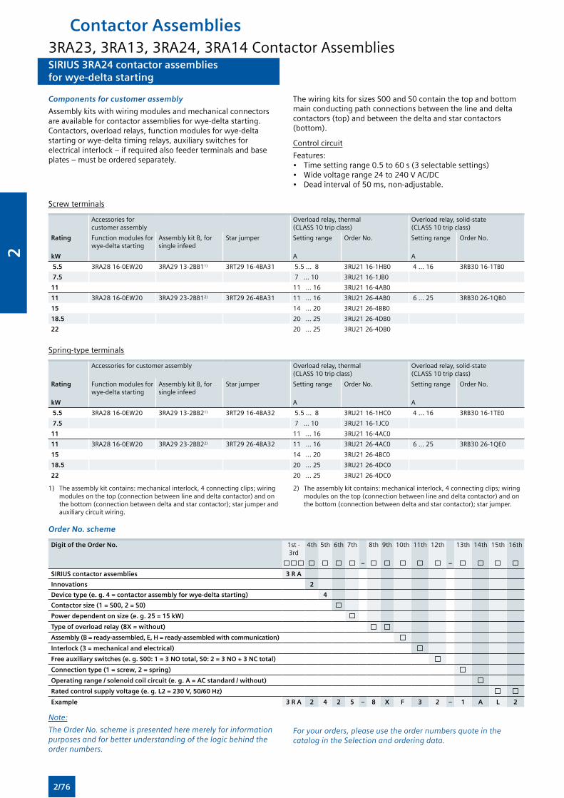
SIRIUS 3RA24 contactor assembliesfor wye-delta starting
SIRIUS 3RA24 contactor assembliesfor wye-delta starting
Components for customer assembly
Assembly kits with wiring modules and mechanical connectors are available for contactor assemblies for wye-delta starting. Contactors, overload relays, function modules for wye-delta starting or wye-delta timing relays, auxiliary switches for electrical interlock – if required also feeder terminals and base plates – must be ordered separately.
The wiring kits for sizes S00 and S0 contain the top and bottom main conducting path connections between the line and delta contactors (top) and between the delta and star contactors (bottom).
Control circuit
Features:• Time setting range 0.5 to 60 s (3 selectable settings)• Wide voltage range 24 to 240 V AC/DC• Dead interval of 50 ms, non-adjustable.
Screw terminals
Accessories for customer assembly
Overload relay, thermal (CLASS 10 trip class)
Overload relay, solid-state (CLASS 10 trip class)
Rating Function modules for wye-delta starting
Assembly kit B, for single infeed
Star jumper Setting range Order No. Setting range Order No.
kW A A
5.5 3RA28 16-0EW20 3RA29 13-2BB11) 3RT29 16-4BA31 5.5 ... 8 3RU21 16-1HB0 4 ... 16 3RB30 16-1TB0
7.5 7 ... 10 3RU21 16-1JB0
11 11 ... 16 3RU21 16-4AB0
11 3RA28 16-0EW20 3RA29 23-2BB12) 3RT29 26-4BA31 11 ... 16 3RU21 26-4AB0 6 ... 25 3RB30 26-1QB0
15 14 ... 20 3RU21 26-4BB0
18.5 20 ... 25 3RU21 26-4DB0
22 20 ... 25 3RU21 26-4DB0
Spring-type terminals
Accessories for customer assembly Overload relay, thermal (CLASS 10 trip class)
Overload relay, solid-state (CLASS 10 trip class)
Rating Function modules for wye-delta starting
Assembly kit B, for single infeed
Star jumper Setting range Order No. Setting range Order No.
kW A A
5.5 3RA28 16-0EW20 3RA29 13-2BB21) 3RT29 16-4BA32 5.5 ... 8 3RU21 16-1HC0 4 ... 16 3RB30 16-1TE0
7.5 7 ... 10 3RU21 16-1JC0
11 11 ... 16 3RU21 16-4AC0
11 3RA28 16-0EW20 3RA29 23-2BB22) 3RT29 26-4BA32 11 ... 16 3RU21 26-4AC0 6 ... 25 3RB30 26-1QE0
15 14 ... 20 3RU21 26-4BC0
18.5 20 ... 25 3RU21 26-4DC0
22 20 ... 25 3RU21 26-4DC0
1) The assembly kit contains: mechanical interlock, 4 connecting clips; wiring modules on the top (connection between line and delta contactor) and on the bottom (connection between delta and star contactor); star jumper and auxiliary circuit wiring.
2) The assembly kit contains: mechanical interlock, 4 connecting clips; wiring modules on the top (connection between line and delta contactor) and on the bottom (connection between delta and star contactor); star jumper.
Order No. scheme
Digit of the Order No. 1st - 3rd
4th 5th 6th 7th 8th 9th 10th 11th 12th 13th 14th 15th 16th
– –
SIRIUS contactor assemblies 3 R A
Innovations 2
Device type (e. g. 4 = contactor assembly for wye-delta starting) 4
Contactor size (1 = S00, 2 = S0)
Power dependent on size (e. g. 25 = 15 kW)
Type of overload relay (8X = without)
Assembly (B = ready-assembled, E, H = ready-assembled with communication)
Interlock (3 = mechanical and electrical)
Free auxiliary switches (e. g. S00: 1 = 3 NO total, S0: 2 = 3 NO + 3 NC total)
Connection type (1 = screw, 2 = spring)
Operating range / solenoid coil circuit (e. g. A = AC standard / without)
Rated control supply voltage (e. g. L2 = 230 V, 50/60 Hz)
Example 3 R A 2 4 2 5 – 8 X F 3 2 – 1 A L 2
Note:
The Order No. scheme is presented here merely for information purposes and for better understanding of the logic behind the order numbers.
For your orders, please use the order numbers quote in the catalog in the Selection and ordering data.
Contactor Assemblies3RA23, 3RA13, 3RA24, 3RA14 Contactor Assemblies
2/76
2
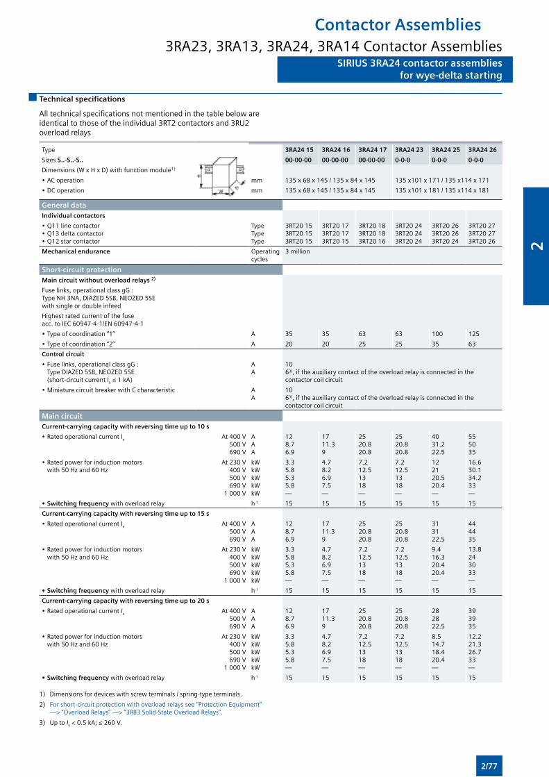
SIRIUS 3RA24 contactor assembliesfor wye-delta starting
SIRIUS 3RA24 contactor assembliesfor wye-delta starting
Technical specifications
All technical specifications not mentioned in the table below are identical to those of the individual 3RT2 contactors and 3RU2 overload relays
Type 3RA24 15 3RA24 16 3RA24 17 3RA24 23 3RA24 25 3RA24 26
Sizes S..-S..-S.. 00-00-00 00-00-00 00-00-00 0-0-0 0-0-0 0-0-0
Dimensions (W x H x D) with function module1)
• AC operation mm 135 x 68 x 145 / 135 x 84 x 145 135 x101 x 171 / 135 x114 x 171
• DC operation mm 135 x 68 x 145 / 135 x 84 x 145 135 x101 x 181 / 135 x114 x 181
General dataIndividual contactors
• Q11 line contactor • Q13 delta contactor• Q12 star contactor
TypeTypeType
3RT20 153RT20 153RT20 15
3RT20 173RT20 173RT20 15
3RT20 183RT20 183RT20 16
3RT20 243RT20 243RT20 24
3RT20 263RT20 263RT20 24
3RT20 273RT20 273RT20 26
Mechanical endurance Operating cycles
3 million
Short-circuit protectionMain circuit without overload relays 2)
Fuse links, operational class gG : Type NH 3NA, DIAZED 5SB, NEOZED 5SE with single or double infeed
Highest rated current of the fuse acc. to IEC 60947-4-1/EN 60947-4-1
• Type of coordination “1” A 35 35 63 63 100 125
• Type of coordination “2” A 20 20 25 25 35 63
Control circuit
• Fuse links, operational class gG : Type DIAZED 5SB, NEOZED 5SE (short-circuit current Ik ≤ 1 kA)
AA
10 63), if the auxiliary contact of the overload relay is connected in the contactor coil circuit
• Miniature circuit breaker with C characteristic AA
10 63), if the auxiliary contact of the overload relay is connected in the contactor coil circuit
Main circuitCurrent-carrying capacity with reversing time up to 10 s
• Rated operational current Ie At 400 V500 V690 V
AAA
128.76.9
1711.39
2520.820.8
2520.820.8
4031.222.5
555035
• Rated power for induction motors with 50 Hz and 60 Hz
At 230 V400 V500 V690 V
1 000 V
kWkWkWkWkW
3.35.85.35.8—
4.78.26.97.5—
7.212.51318—
7.212.51318—
122120.520.4—
16.630.134.233—
• Switching frequency with overload relay h-1 15 15 15 15 15 15
Current-carrying capacity with reversing time up to 15 s
• Rated operational current Ie At 400 V500 V690 V
AAA
128.76.9
1711.39
2520.820.8
2520.820.8
313122.5
444435
• Rated power for induction motors with 50 Hz and 60 Hz
At 230 V400 V500 V690 V
1 000 V
kWkWkWkWkW
3.35.85.35.8—
4.78.26.97.5—
7.212.51318—
7.212.51318—
9.416.320.420.4—
13.8243033—
• Switching frequency with overload relay h-1 15 15 15 15 15 15
Current-carrying capacity with reversing time up to 20 s
• Rated operational current Ie At 400 V500 V690 V
AAA
128.76.9
1711.39
2520.820.8
2520.820.8
282822.5
393935
• Rated power for induction motors with 50 Hz and 60 Hz
At 230 V400 V500 V690 V
1 000 V
kWkWkWkWkW
3.35.85.35.8—
4.78.26.97.5—
7.212.51318—
7.212.51318—
8.514.718.420.4—
12.221.326.733—
• Switching frequency with overload relay h-1 15 15 15 15 15 15
1) Dimensions for devices with screw terminals / spring-type terminals.
2) For short-circuit protection with overload relays see “Protection Equipment” —> “Overload Relays” —> “3RB3 Solid-State Overload Relays”.
3) Up to Ik < 0.5 kA; ≤ 260 V.
Contactor Assemblies3RA23, 3RA13, 3RA24, 3RA14 Contactor Assemblies
2/77
2
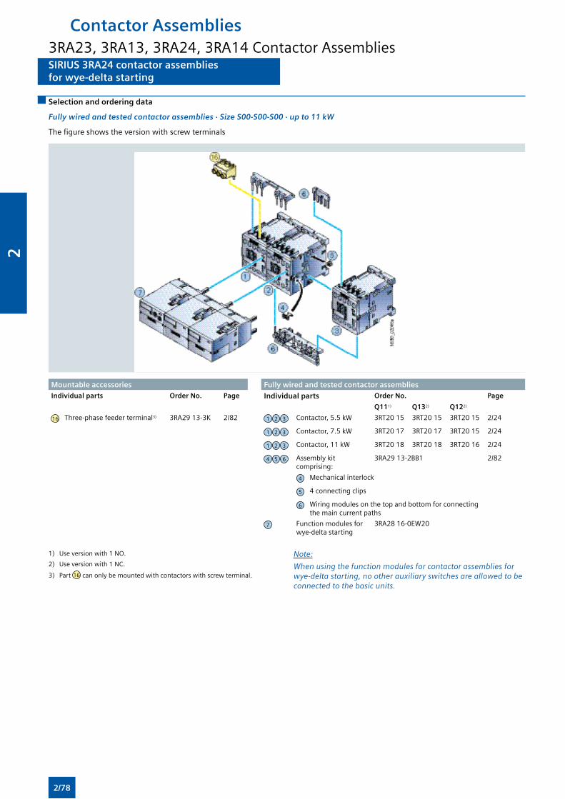
SIRIUS 3RA24 contactor assembliesfor wye-delta starting
SIRIUS 3RA24 contactor assembliesfor wye-delta starting
Selection and ordering data
Fully wired and tested contactor assemblies · Size S00-S00-S00 · up to 11 kW
The figure shows the version with screw terminals
Mountable accessories Fully wired and tested contactor assembliesIndividual parts Order No. Page Individual parts Order No. Page
Q111) Q132) Q122)
16 Three-phase feeder terminal3) 3RA29 13-3K 2/82 1 2 3 Contactor, 5.5 kW 3RT20 15 3RT20 15 3RT20 15 2/24
1 2 3 Contactor, 7.5 kW 3RT20 17 3RT20 17 3RT20 15 2/24
1 2 3 Contactor, 11 kW 3RT20 18 3RT20 18 3RT20 16 2/24
4 5 6 Assembly kit comprising:
3RA29 13-2BB1 2/82
4 Mechanical interlock
5 4 connecting clips
6 Wiring modules on the top and bottom for connecting the main current paths
7 Function modules for wye-delta starting
3RA28 16-0EW20
1) Use version with 1 NO.
2) Use version with 1 NC.
3) Part 16 can only be mounted with contactors with screw terminal.
Note:
When using the function modules for contactor assemblies for wye-delta starting, no other auxiliary switches are allowed to be connected to the basic units.
Contactor Assemblies3RA23, 3RA13, 3RA24, 3RA14 Contactor Assemblies
2/78
2
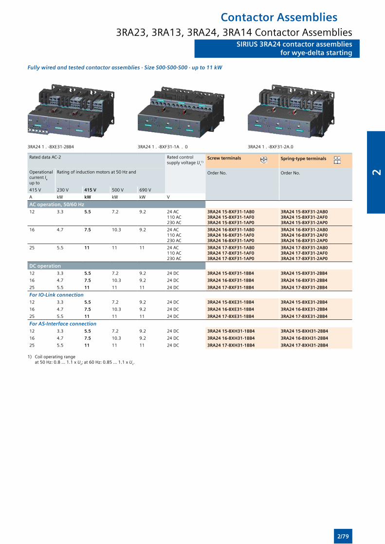
SIRIUS 3RA24 contactor assembliesfor wye-delta starting
SIRIUS 3RA24 contactor assembliesfor wye-delta starting
Fully wired and tested contactor assemblies · Size S00-S00-S00 · up to 11 kW
3RA24 1 . -8XE31-2BB4 3RA24 1 . -8XF31-1A . 0 3RA24 1 . -8XF31-2A.0
Rated data AC-2 Rated control supply voltage Us
1)Screw terminals Spring-type terminals
Operational current Ie
up to
Rating of induction motors at 50 Hz and Order No. Order No.
415 V 230 V 415 V 500 V 690 V
A kW kW kW kW V
AC operation, 50/60 Hz12 3.3 5.5 7.2 9.2 24 AC
110 AC230 AC
3RA24 15-8XF31-1AB03RA24 15-8XF31-1AF03RA24 15-8XF31-1AP0
3RA24 15-8XF31-2AB03RA24 15-8XF31-2AF03RA24 15-8XF31-2AP0
16 4.7 7.5 10.3 9.2 24 AC110 AC230 AC
3RA24 16-8XF31-1AB03RA24 16-8XF31-1AF03RA24 16-8XF31-1AP0
3RA24 16-8XF31-2AB03RA24 16-8XF31-2AF03RA24 16-8XF31-2AP0
25 5.5 11 11 11 24 AC110 AC230 AC
3RA24 17-8XF31-1AB03RA24 17-8XF31-1AF03RA24 17-8XF31-1AP0
3RA24 17-8XF31-2AB03RA24 17-8XF31-2AF03RA24 17-8XF31-2AP0
DC operation12 3.3 5.5 7.2 9.2 24 DC 3RA24 15-8XF31-1BB4 3RA24 15-8XF31-2BB4
16 4.7 7.5 10.3 9.2 24 DC 3RA24 16-8XF31-1BB4 3RA24 16-8XF31-2BB4
25 5.5 11 11 11 24 DC 3RA24 17-8XF31-1BB4 3RA24 17-8XF31-2BB4
For IO-Link connection12 3.3 5.5 7.2 9.2 24 DC 3RA24 15-8XE31-1BB4 3RA24 15-8XE31-2BB4
16 4.7 7.5 10.3 9.2 24 DC 3RA24 16-8XE31-1BB4 3RA24 16-8XE31-2BB4
25 5.5 11 11 11 24 DC 3RA24 17-8XE31-1BB4 3RA24 17-8XE31-2BB4
For AS-Interface connection12 3.3 5.5 7.2 9.2 24 DC 3RA24 15-8XH31-1BB4 3RA24 15-8XH31-2BB4
16 4.7 7.5 10.3 9.2 24 DC 3RA24 16-8XH31-1BB4 3RA24 16-8XH31-2BB4
25 5.5 11 11 11 24 DC 3RA24 17-8XH31-1BB4 3RA24 17-8XH31-2BB4
1) Coil operating range at 50 Hz: 0.8 ... 1.1 x Us; at 60 Hz: 0.85 ... 1.1 x Us.
Contactor Assemblies3RA23, 3RA13, 3RA24, 3RA14 Contactor Assemblies
2/79
2
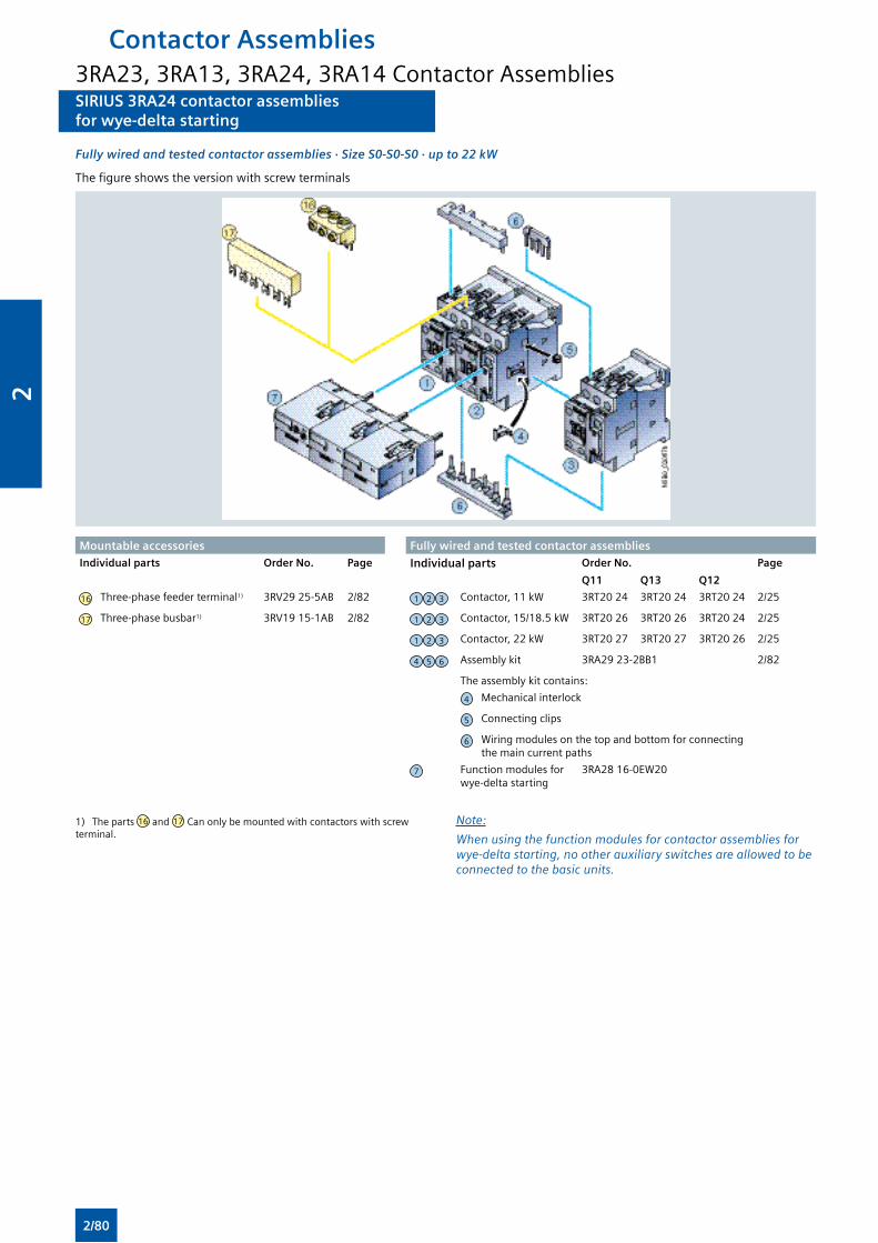
SIRIUS 3RA24 contactor assembliesfor wye-delta starting
SIRIUS 3RA24 contactor assembliesfor wye-delta starting
Fully wired and tested contactor assemblies · Size S0-S0-S0 · up to 22 kW
The figure shows the version with screw terminals
Mountable accessories Fully wired and tested contactor assembliesIndividual parts Order No. Page Individual parts Order No. Page
Q11 Q13 Q12
16 Three-phase feeder terminal1) 3RV29 25-5AB 2/82 1 2 3 Contactor, 11 kW 3RT20 24 3RT20 24 3RT20 24 2/25
17 Three-phase busbar1) 3RV19 15-1AB 2/82 1 2 3 Contactor, 15/18.5 kW 3RT20 26 3RT20 26 3RT20 24 2/25
1 2 3 Contactor, 22 kW 3RT20 27 3RT20 27 3RT20 26 2/25
4 5 6 Assembly kit 3RA29 23-2BB1 2/82
The assembly kit contains:
4 Mechanical interlock
5 Connecting clips
6 Wiring modules on the top and bottom for connecting the main current paths
7 Function modules for wye-delta starting
3RA28 16-0EW20
1) The parts 16 and 17 Can only be mounted with contactors with screw terminal.
Note:
When using the function modules for contactor assemblies for wye-delta starting, no other auxiliary switches are allowed to be connected to the basic units.
Contactor Assemblies3RA23, 3RA13, 3RA24, 3RA14 Contactor Assemblies
2/80
2
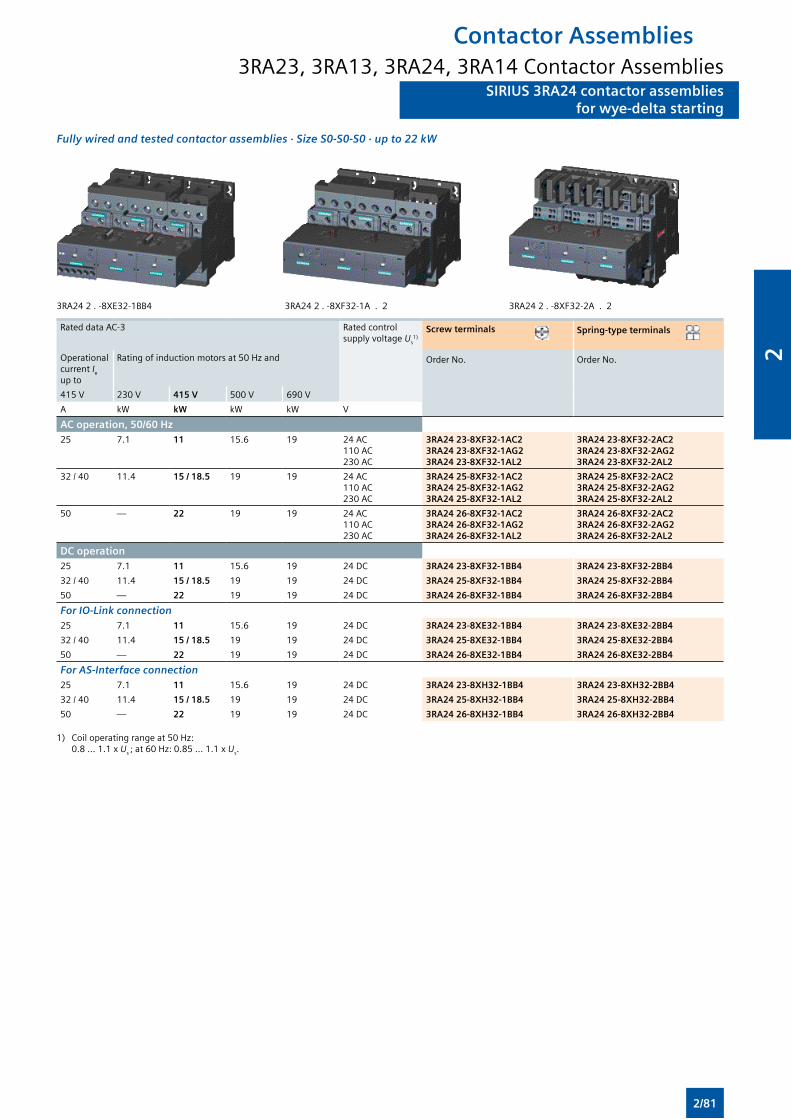
SIRIUS 3RA24 contactor assembliesfor wye-delta starting
SIRIUS 3RA24 contactor assembliesfor wye-delta starting
Fully wired and tested contactor assemblies · Size S0-S0-S0 · up to 22 kW
3RA24 2 . -8XE32-1BB4 3RA24 2 . -8XF32-1A . 2 3RA24 2 . -8XF32-2A . 2
Rated data AC-3 Rated control supply voltage Us
1)Screw terminals Spring-type terminals
Operational current Ie
up to
Rating of induction motors at 50 Hz and Order No. Order No.
415 V 230 V 415 V 500 V 690 V
A kW kW kW kW V
AC operation, 50/60 Hz25 7.1 11 15.6 19 24 AC
110 AC230 AC
3RA24 23-8XF32-1AC23RA24 23-8XF32-1AG23RA24 23-8XF32-1AL2
3RA24 23-8XF32-2AC23RA24 23-8XF32-2AG23RA24 23-8XF32-2AL2
32 / 40 11.4 15 / 18.5 19 19 24 AC110 AC230 AC
3RA24 25-8XF32-1AC23RA24 25-8XF32-1AG23RA24 25-8XF32-1AL2
3RA24 25-8XF32-2AC23RA24 25-8XF32-2AG23RA24 25-8XF32-2AL2
50 — 22 19 19 24 AC110 AC230 AC
3RA24 26-8XF32-1AC23RA24 26-8XF32-1AG23RA24 26-8XF32-1AL2
3RA24 26-8XF32-2AC23RA24 26-8XF32-2AG23RA24 26-8XF32-2AL2
DC operation25 7.1 11 15.6 19 24 DC 3RA24 23-8XF32-1BB4 3RA24 23-8XF32-2BB4
32 / 40 11.4 15 / 18.5 19 19 24 DC 3RA24 25-8XF32-1BB4 3RA24 25-8XF32-2BB4
50 — 22 19 19 24 DC 3RA24 26-8XF32-1BB4 3RA24 26-8XF32-2BB4
For IO-Link connection25 7.1 11 15.6 19 24 DC 3RA24 23-8XE32-1BB4 3RA24 23-8XE32-2BB4
32 / 40 11.4 15 / 18.5 19 19 24 DC 3RA24 25-8XE32-1BB4 3RA24 25-8XE32-2BB4
50 — 22 19 19 24 DC 3RA24 26-8XE32-1BB4 3RA24 26-8XE32-2BB4
For AS-Interface connection25 7.1 11 15.6 19 24 DC 3RA24 23-8XH32-1BB4 3RA24 23-8XH32-2BB4
32 / 40 11.4 15 / 18.5 19 19 24 DC 3RA24 25-8XH32-1BB4 3RA24 25-8XH32-2BB4
50 — 22 19 19 24 DC 3RA24 26-8XH32-1BB4 3RA24 26-8XH32-2BB4
1) Coil operating range at 50 Hz: 0.8 ... 1.1 x Us ; at 60 Hz: 0.85 ... 1.1 x Us.
Contactor Assemblies3RA23, 3RA13, 3RA24, 3RA14 Contactor Assemblies
2/81
2
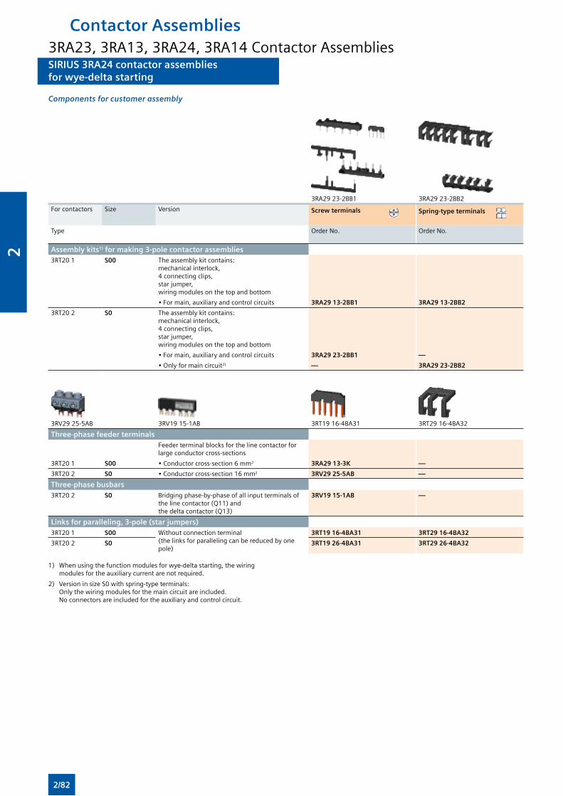
SIRIUS 3RA24 contactor assembliesfor wye-delta starting
SIRIUS 3RA24 contactor assembliesfor wye-delta starting
Components for customer assembly
3RA29 23-2BB1 3RA29 23-2BB2
For contactors Size Version Screw terminals Spring-type terminals
Type Order No. Order No.
Assembly kits1) for making 3-pole contactor assemblies3RT20 1 S00 The assembly kit contains:
mechanical interlock, 4 connecting clips, star jumper,wiring modules on the top and bottom
• For main, auxiliary and control circuits 3RA29 13-2BB1 3RA29 13-2BB2
3RT20 2 S0 The assembly kit contains: mechanical interlock, 4 connecting clips, star jumper,wiring modules on the top and bottom
• For main, auxiliary and control circuits 3RA29 23-2BB1 —
• Only for main circuit2) — 3RA29 23-2BB2
3RV29 25-5AB 3RV19 15-1AB 3RT19 16-4BA31 3RT29 16-4BA32
Three-phase feeder terminals Feeder terminal blocks for the line contactor for large conductor cross-sections
3RT20 1 S00 • Conductor cross-section 6 mm2 3RA29 13-3K —
3RT20 2 S0 • Conductor cross-section 16 mm2 3RV29 25-5AB —
Three-phase busbars 3RT20 2 S0 Bridging phase-by-phase of all input terminals of
the line contactor (Q11) and the delta contactor (Q13)
3RV19 15-1AB —
Links for paralleling, 3-pole (star jumpers)3RT20 1 S00 Without connection terminal
(the links for paralleling can be reduced by one pole)
3RT19 16-4BA31 3RT29 16-4BA32
3RT20 2 S0 3RT19 26-4BA31 3RT29 26-4BA32
1) When using the function modules for wye-delta starting, the wiring modules for the auxiliary current are not required.
2) Version in size S0 with spring-type terminals: Only the wiring modules for the main circuit are included. No connectors are included for the auxiliary and control circuit.
Contactor Assemblies3RA23, 3RA13, 3RA24, 3RA14 Contactor Assemblies
2/82
2
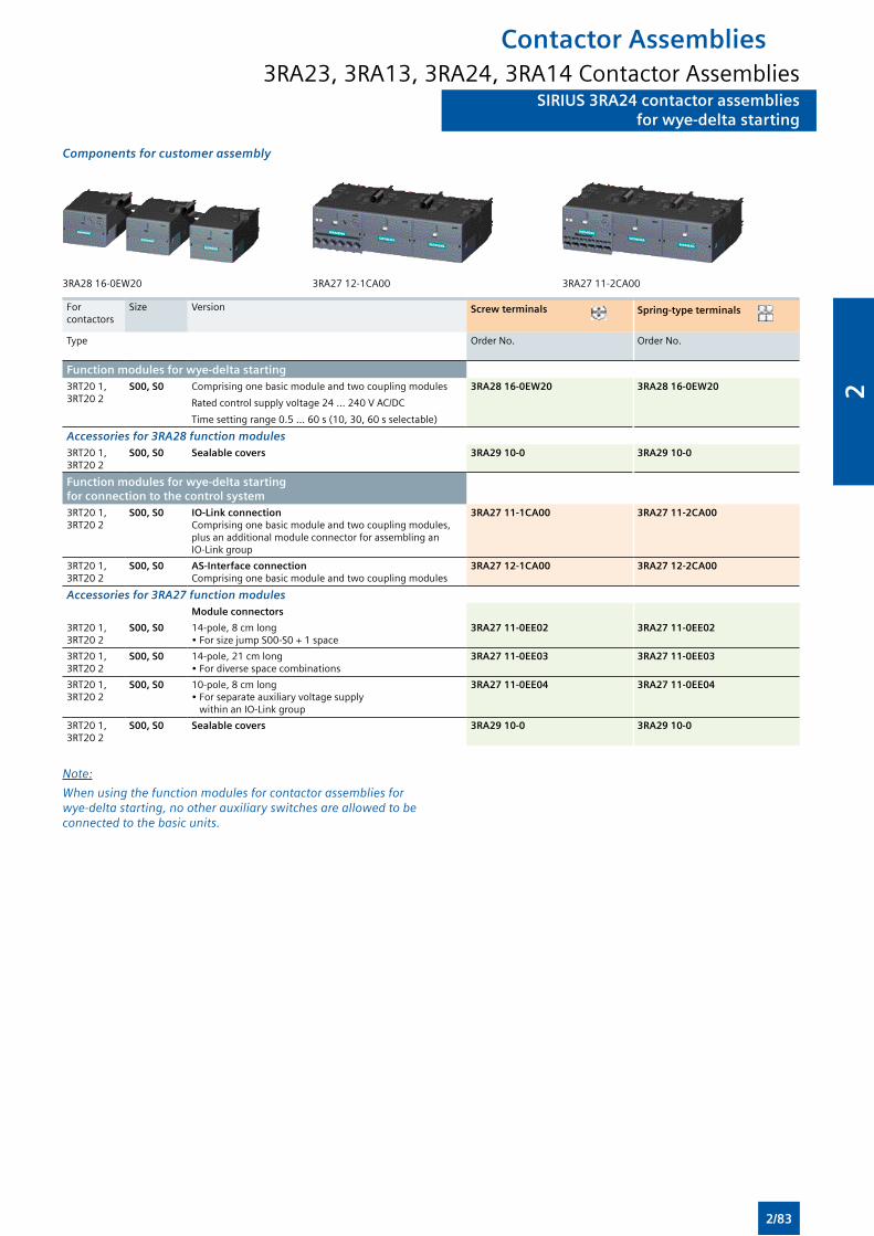
SIRIUS 3RA24 contactor assembliesfor wye-delta starting
SIRIUS 3RA24 contactor assembliesfor wye-delta starting
Components for customer assembly
3RA28 16-0EW20 3RA27 12-1CA00 3RA27 11-2CA00
For contactors
Size Version Screw terminals Spring-type terminals
Type Order No. Order No.
Function modules for wye-delta starting3RT20 1, 3RT20 2
S00, S0 Comprising one basic module and two coupling modules
Rated control supply voltage 24 ... 240 V AC/DC
Time setting range 0.5 ... 60 s (10, 30, 60 s selectable)
3RA28 16-0EW20 3RA28 16-0EW20
Accessories for 3RA28 function modules3RT20 1, 3RT20 2
S00, S0 Sealable covers 3RA29 10-0 3RA29 10-0
Function modules for wye-delta starting for connection to the control system3RT20 1, 3RT20 2
S00, S0 IO-Link connection Comprising one basic module and two coupling modules, plus an additional module connector for assembling an IO-Link group
3RA27 11-1CA00 3RA27 11-2CA00
3RT20 1, 3RT20 2
S00, S0 AS-Interface connectionComprising one basic module and two coupling modules
3RA27 12-1CA00 3RA27 12-2CA00
Accessories for 3RA27 function modulesModule connectors
3RT20 1, 3RT20 2
S00, S0 14-pole, 8 cm long• For size jump S00-S0 + 1 space
3RA27 11-0EE02 3RA27 11-0EE02
3RT20 1, 3RT20 2
S00, S0 14-pole, 21 cm long• For diverse space combinations
3RA27 11-0EE03 3RA27 11-0EE03
3RT20 1, 3RT20 2
S00, S0 10-pole, 8 cm long• For separate auxiliary voltage supply within an IO-Link group
3RA27 11-0EE04 3RA27 11-0EE04
3RT20 1, 3RT20 2
S00, S0 Sealable covers 3RA29 10-0 3RA29 10-0
Note:
When using the function modules for contactor assemblies for wye-delta starting, no other auxiliary switches are allowed to be connected to the basic units.
Contactor Assemblies3RA23, 3RA13, 3RA24, 3RA14 Contactor Assemblies
2/83
2
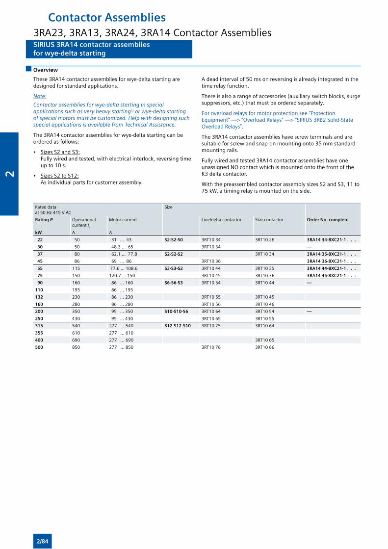
SIRIUS 3RA14 contactor assembliesfor wye-delta starting
SIRIUS 3RA14 contactor assembliesfor wye-delta starting
Overview
These 3RA14 contactor assemblies for wye-delta starting are designed for standard applications.
Note:
Contactor assemblies for wye-delta starting in special applications such as very heavy starting1) or wye-delta starting of special motors must be customized. Help with designing such special applications is available from Technical Assistance.
The 3RA14 contactor assemblies for wye-delta starting can be ordered as follows:
• Sizes S2 and S3: Fully wired and tested, with electrical interlock, reversing time up to 10 s.
• Sizes S2 to S12: As individual parts for customer assembly.
A dead interval of 50 ms on reversing is already integrated in the time relay function.
There is also a range of accessories (auxiliary switch blocks, surge suppressors, etc.) that must be ordered separately.
For overload relays for motor protection see “Protection Equipment” —> “Overload Relays” —> “SIRIUS 3RB2 Solid-State Overload Relays”.
The 3RA14 contactor assemblies have screw terminals and are suitable for screw and snap-on mounting onto 35 mm standard mounting rails.
Fully wired and tested 3RA14 contactor assemblies have one unassigned NO contact which is mounted onto the front of the K3 delta contactor.
With the preassembled contactor assembly sizes S2 and S3, 11 to 75 kW, a timing relay is mounted on the side.
Rated data at 50 Hz 415 V AC
Size
Rating P
kW
Operational current Ie
A
Motor current
A
Line/delta contactor Star contactor Order No. complete
22 50 31 ... 43 S2-S2-S0 3RT10 34 3RT10 26 3RA14 34-8XC21-1 . . .
30 50 48.3 ... 65 3RT10 34 —
37 80 62.1 ... 77.8 S2-S2-S2 3RT10 34 3RA14 35-8XC21-1 . . .
45 86 69 ... 86 3RT10 36 3RA14 36-8XC21-1 . . .
55 115 77.6 ... 108.6 S3-S3-S2 3RT10 44 3RT10 35 3RA14 44-8XC21-1 . . .
75 150 120.7 ... 150 3RT10 45 3RT10 36 3RA14 45-8XC21-1 . . .
90 160 86 ... 160 S6-S6-S3 3RT10 54 3RT10 44 —
110 195 86 ... 195
132 230 86 ... 230 3RT10 55 3RT10 45
160 280 86 ... 280 3RT10 56 3RT10 46
200 350 95 ... 350 S10-S10-S6 3RT10 64 3RT10 54 —
250 430 95 ... 430 3RT10 65 3RT10 55
315 540 277 ... 540 S12-S12-S10 3RT10 75 3RT10 64 —
355 610 277 ... 610
400 690 277 ... 690 3RT10 65
500 850 277 ... 850 3RT10 76 3RT10 66
Contactor Assemblies3RA23, 3RA13, 3RA24, 3RA14 Contactor Assemblies
2/84
2
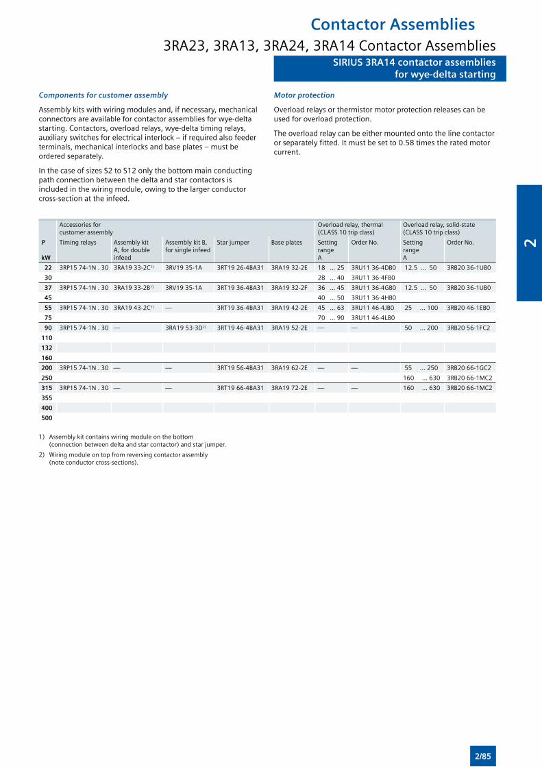
SIRIUS 3RA14 contactor assembliesfor wye-delta starting
SIRIUS 3RA14 contactor assembliesfor wye-delta starting
Components for customer assembly
Assembly kits with wiring modules and, if necessary, mechanical connectors are available for contactor assemblies for wye-delta starting. Contactors, overload relays, wye-delta timing relays, auxiliary switches for electrical interlock – if required also feeder terminals, mechanical interlocks and base plates – must be ordered separately.
In the case of sizes S2 to S12 only the bottom main conducting path connection between the delta and star contactors is included in the wiring module, owing to the larger conductor cross-section at the infeed.
Motor protection
Overload relays or thermistor motor protection releases can be used for overload protection.
The overload relay can be either mounted onto the line contactor or separately fitted. It must be set to 0.58 times the rated motor current.
Accessories for customer assembly
Overload relay, thermal (CLASS 10 trip class)
Overload relay, solid-state (CLASS 10 trip class)
P
kW
Timing relays Assembly kit A, for double infeed
Assembly kit B, for single infeed
Star jumper Base plates Setting range A
Order No. Setting range A
Order No.
22 3RP15 74-1N . 30 3RA19 33-2C1) 3RV19 35-1A 3RT19 26-4BA31 3RA19 32-2E 18 ... 25 3RU11 36-4DB0 12.5 ... 50 3RB20 36-1UB0
30 28 ... 40 3RU11 36-4FB0
37 3RP15 74-1N . 30 3RA19 33-2B1) 3RV19 35-1A 3RT19 36-4BA31 3RA19 32-2F 36 ... 45 3RU11 36-4GB0 12.5 ... 50 3RB20 36-1UB0
45 40 ... 50 3RU11 36-4HB0
55 3RP15 74-1N . 30 3RA19 43-2C1) — 3RT19 36-4BA31 3RA19 42-2E 45 ... 63 3RU11 46-4JB0 25 ... 100 3RB20 46-1EB0
75 70 ... 90 3RU11 46-4LB0
90 3RP15 74-1N . 30 — 3RA19 53-3D2) 3RT19 46-4BA31 3RA19 52-2E — — 50 ... 200 3RB20 56-1FC2
110
132
160
200 3RP15 74-1N . 30 — — 3RT19 56-4BA31 3RA19 62-2E — — 55 ... 250 3RB20 66-1GC2
250 160 ... 630 3RB20 66-1MC2
315 3RP15 74-1N . 30 — — 3RT19 66-4BA31 3RA19 72-2E — — 160 ... 630 3RB20 66-1MC2
355
400
500
1) Assembly kit contains wiring module on the bottom (connection between delta and star contactor) and star jumper.
2) Wiring module on top from reversing contactor assembly (note conductor cross-sections).
Contactor Assemblies3RA23, 3RA13, 3RA24, 3RA14 Contactor Assemblies
2/85
2
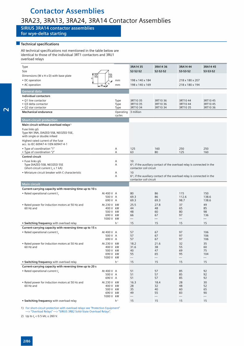
SIRIUS 3RA14 contactor assembliesfor wye-delta starting
SIRIUS 3RA14 contactor assembliesfor wye-delta starting
Technical specifications
All technical specifications not mentioned in the table below are identical to those of the individual 3RT1 contactors and 3RU1 overload relays
Type 3RA14 35 3RA14 36 3RA14 44 3RA14 45
Size S2-S2-S2 S2-S2-S2 S3-S3-S2 S3-S3-S2
Dimensions (W x H x D) with base plate
• DC operation mm 198 x 140 x 184 218 x 180 x 207
• AC operation mm 198 x 140 x 169 218 x 180 x 194
General dataIndividual contactors
• Q1 line contactor• Q3 delta contactor• Q2 star contactor
TypeTypeType
3RT10 353RT10 353RT10 34
3RT10 363RT10 363RT10 34
3RT10 443RT10 443RT10 35
3RT10 453RT10 453RT10 36
Mechanical endurance Operating cycles
3 million
Short-circuit protectionMain circuit without overload relays1)
Fuse links gG Type NH 3NA, DIAZED 5SB, NEOZED 5SE, with single or double infeed
Highest rated current of the fuse acc. to IEC 60947-4-1/EN 60947-4-1
• Type of coordination “1”• Type of coordination “2”
AA
12563
16080
250125
250160
Control circuit
• Fuse links gG Type DIAZED 5SB, NEOZED 5SE (short-circuit current Ik ≤ 1 kA)
AA
10 62), if the auxiliary contact of the overload relay is connected in the contactor coil circuit
• Miniature circuit breaker with C characteristic AA
10 62), if the auxiliary contact of the overload relay is connected in the contactor coil circuit
Main circuitCurrent-carrying capacity with reversing time up to 10 s
• Rated operational current Ie At 400 V500 V690 V
AAA
8069.369.3
868669.3
115112.698.7
150138.6138.6
• Rated power for induction motors at 50 Hz and 60 Hz and
At 230 V400 V500 V690 V
1000 V
kWkWkWkWkW
25.5444866—
27.8486067—
37658097—
498598136—
• Switching frequency with overload relay h-1 15 15 15 15
Current-carrying capacity with reversing time up to 15 s
• Rated operational current Ie At 400 V500 V690 V
AAA
575757
676767
979797
106106106
• Rated power for induction motors at 50 Hz and 60 Hz and
At 230 V400 V500 V690 V
1000 V
kWkWkWkWkW
18.231.64055—
21.6384765—
32556995—
356075104—
• Switching frequency with overload relay h-1 15 15 15 15
Current-carrying capacity with reversing time up to 20 s
• Rated operational current Ie At 400 V500 V690 V
AAA
515151
575757
858585
929292
• Rated power for induction motors at 50 Hz and 60 Hz and
At 230 V400 V500 V690 V
1000 V
kWkWkWkWkW
16.3283549—
18.4324055—
28486083—
30526590—
• Switching frequency with overload relay h-1 15 15 15 15
1) For short-circuit protection with overload relays see “Protection Equipment” —> “Overload Relays” —> “SIRIUS 3RB2 Solid-State Overload Relays”.
2) Up to Ik < 0.5 kA; ≤ 260 V.
Contactor Assemblies3RA23, 3RA13, 3RA24, 3RA14 Contactor Assemblies
2/86
2
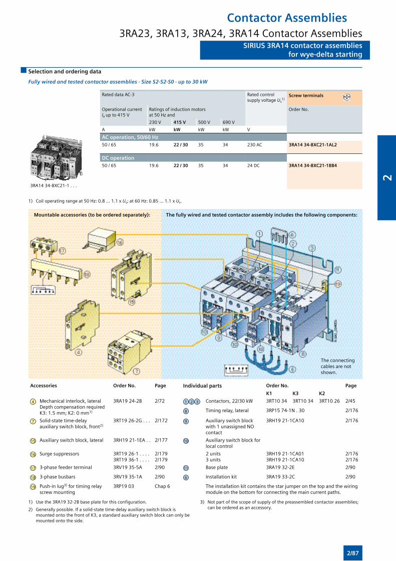
SIRIUS 3RA14 contactor assembliesfor wye-delta starting
SIRIUS 3RA14 contactor assembliesfor wye-delta starting
Selection and ordering data
Fully wired and tested contactor assemblies · Size S2-S2-S0 · up to 30 kW
Rated data AC-3 Rated control supply voltage Us
1)Screw terminals
Operational current Ie up to 415 V
Ratings of induction motors at 50 Hz and
Order No.
230 V 415 V 500 V 690 V
A kW kW kW kW V
3RA14 34-8XC21-1 . . .
AC operation, 50/60 Hz50 / 65 19.6 22 / 30 35 34 230 AC 3RA14 34-8XC21-1AL2
DC operation50 / 65 19.6 22 / 30 35 34 24 DC 3RA14 34-8XC21-1BB4
1) Coil operating range at 50 Hz: 0.8 ... 1.1 x Us; at 60 Hz: 0.85 ... 1.1 x Us.
Accessories Order No. Page Individual parts Order No. Page
K1 K3 K2
4 Mechanical interlock, lateral Depth compensation required K3: 1.5 mm; K2: 0 mm1)
3RA19 24-2B 2/72 1 2 3 Contactors, 22/30 kW 3RT10 34 3RT10 34 3RT10 26 2/45
8 Timing relay, lateral 3RP15 74-1N . 30 2/176
7 Solid-state time-delay auxiliary switch block, front2)
3RT19 26-2G . . . 2/172 9 Auxiliary switch block with 1 unassigned NO contact
3RH19 21-1CA10 2/176
15 Auxiliary switch block, lateral 3RH19 21-1EA . . 2/177 10 Auxiliary switch block for local control
16 Surge suppressors 3RT19 26-1 . . . . 3RT19 36-1 . . . .
2/1792/179
2 units3 units
3RH19 21-1CA013RH19 21-1CA10
2/1762/176
17 3-phase feeder terminal 3RV19 35-5A 2/90 11 Base plate 3RA19 32-2E 2/90
18 3-phase busbars 3RV19 35-1A 2/90 6 Installation kit 3RA19 33-2C 2/90
19 Push-in lug3) for timing relay screw mounting
3RP19 03 Chap 6 The installation kit contains the star jumper on the top and the wiring module on the bottom for connecting the main current paths.
Mountable accessories (to be ordered separately): The fully wired and tested contactor assembly includes the following components:
1) Use the 3RA19 32-2B base plate for this configuration.
2) Generally possible. If a solid-state time-delay auxiliary switch block is mounted onto the front of K3, a standard auxiliary switch block can only be mounted onto the side.
3) Not part of the scope of supply of the preassembled contactor assemblies; can be ordered as an accessory.
Contactor Assemblies3RA23, 3RA13, 3RA24, 3RA14 Contactor Assemblies
The connecting cables are not shown.
2/87
2
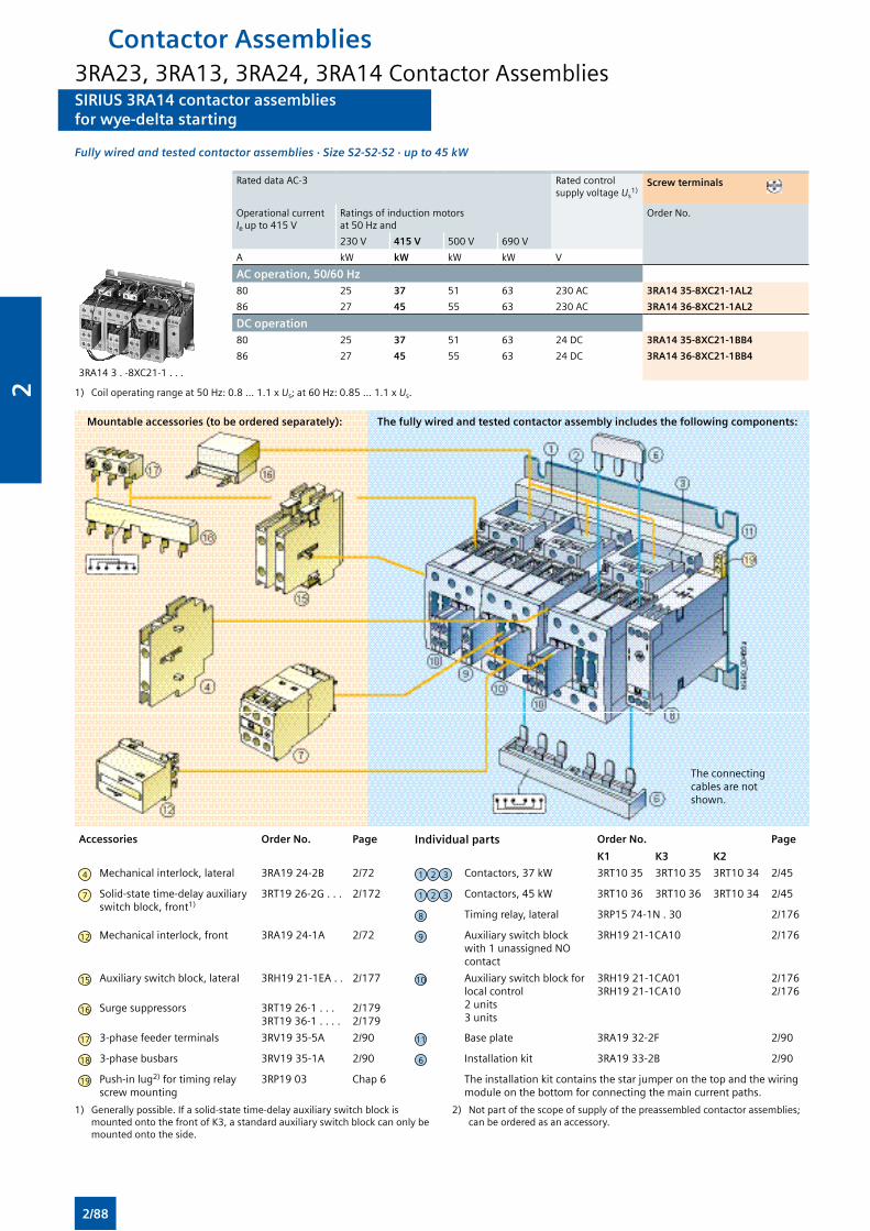
SIRIUS 3RA14 contactor assembliesfor wye-delta starting
SIRIUS 3RA14 contactor assembliesfor wye-delta starting
Fully wired and tested contactor assemblies · Size S2-S2-S2 · up to 45 kW
Rated data AC-3 Rated control supply voltage Us
1)Screw terminals
Operational current Ie up to 415 V
Ratings of induction motors at 50 Hz and
Order No.
230 V 415 V 500 V 690 V
A kW kW kW kW V
3RA14 3 . -8XC21-1 . . .
AC operation, 50/60 Hz80 25 37 51 63 230 AC 3RA14 35-8XC21-1AL2
86 27 45 55 63 230 AC 3RA14 36-8XC21-1AL2
DC operation80 25 37 51 63 24 DC 3RA14 35-8XC21-1BB4
86 27 45 55 63 24 DC 3RA14 36-8XC21-1BB4
1) Coil operating range at 50 Hz: 0.8 ... 1.1 x Us; at 60 Hz: 0.85 ... 1.1 x Us.
Accessories Order No. Page Individual parts Order No. Page
K1 K3 K2
4 Mechanical interlock, lateral 3RA19 24-2B 2/72 1 2 3 Contactors, 37 kW 3RT10 35 3RT10 35 3RT10 34 2/45
7 Solid-state time-delay auxiliary switch block, front1)
3RT19 26-2G . . . 2/172 1 2 3 Contactors, 45 kW 3RT10 36 3RT10 36 3RT10 34 2/45
8 Timing relay, lateral 3RP15 74-1N . 30 2/176
12 Mechanical interlock, front 3RA19 24-1A 2/72 9 Auxiliary switch block with 1 unassigned NO contact
3RH19 21-1CA10 2/176
15 Auxiliary switch block, lateral 3RH19 21-1EA . . 2/177 10 Auxiliary switch block for local control 2 units 3 units
3RH19 21-1CA013RH19 21-1CA10
2/1762/176
16 Surge suppressors 3RT19 26-1 . . . 3RT19 36-1 . . . .
2/1792/179
17 3-phase feeder terminals 3RV19 35-5A 2/90 11 Base plate 3RA19 32-2F 2/90
18 3-phase busbars 3RV19 35-1A 2/90 6 Installation kit 3RA19 33-2B 2/90
19 Push-in lug2) for timing relay screw mounting
3RP19 03 Chap 6 The installation kit contains the star jumper on the top and the wiring module on the bottom for connecting the main current paths.
Mountable accessories (to be ordered separately): The fully wired and tested contactor assembly includes the following components:
1) Generally possible. If a solid-state time-delay auxiliary switch block is mounted onto the front of K3, a standard auxiliary switch block can only be mounted onto the side.
2) Not part of the scope of supply of the preassembled contactor assemblies; can be ordered as an accessory.
The connecting cables are not shown.
Contactor Assemblies3RA23, 3RA13, 3RA24, 3RA14 Contactor Assemblies
2/88
2
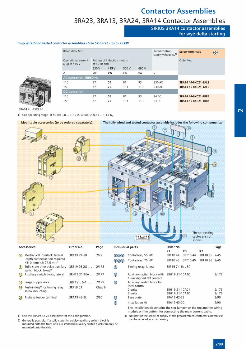
SIRIUS 3RA14 contactor assembliesfor wye-delta starting
SIRIUS 3RA14 contactor assembliesfor wye-delta starting
Fully wired and tested contactor assemblies · Size S2-S3-S2 · up to 75 kW
Rated data AC-3 Rated control supply voltage Us
1)Screw terminals
Operational current Ie up to 415 V
Ratings of induction motors at 50 Hz and
Order No.
230 V 415 V 500 V 690 V
A kW kW kW kW V
3RA14 4 . -8XC21-1 . . .
AC operation, 50/60 Hz115 37 55 81 93 230 AC 3RA14 44-8XC21-1AL2
150 47 75 103 110 230 AC 3RA14 45-8XC21-1AL2
DC operation115 37 55 81 93 24 DC 3RA14 44-8XC21-1BB4
150 47 75 103 110 24 DC 3RA14 45-8XC21-1BB4
1) Coil operating range at 50 Hz: 0.8 ... 1.1 x Us; at 60 Hz: 0.85 ... 1.1 x Us.
Accessories Order No. Page Individual parts Order No. PageK1 K3 K2
4 Mechanical interlock, lateral Depth compensation required K3: 0 mm; K2: 27.5 mm1)
3RA19 24-2B 2/72 1 2 3 Contactors, 55 kW 3RT10 44 3RT10 44 3RT10 35 2/45
1 2 3 Contactors, 75 kW 3RT10 45 3RT10 45 3RT10 36 2/45
7 Solid-state time-delay auxiliary switch block, front2)
3RT19 26-2G . . . 2/178 8 Timing relay, lateral 3RP15 74-1N . 30
15 Auxiliary switch block, lateral 3RH19 21-1EA . . 2/177 9 Auxiliary switch block with 1 unassigned NO contact
3RH19 21-1CA10 2/176
16 Surge suppressors 3RT19 . 6-1 . . . . 2/179 10 Auxiliary switch block for local control 2 units 3 units
3RH19 21-1CA013RH19 21-1CA10
2/1762/176
19 Push-in lug3) for timing relay screw mounting
3RP19 03 Chap 6
20 1-phase feeder terminal 3RA19 43-3L 2/90 11 Base plate 3RA19 42-2E 2/90
6 Installation kit 3RA19 43-2C 2/90
The installation kit contains the star jumper on the top and the wiring module on the bottom for connecting the main current paths.
Mountable accessories (to be ordered separately): The fully wired and tested contactor assembly includes the following components:
The connecting cables are not shown.
1) Use the 3RA19 42-2B base plate for this configuration.
2) Generally possible. If a solid-state time-delay auxiliary switch block is mounted onto the front of K3, a standard auxiliary switch block can only be mounted onto the side.
3) Not part of the scope of supply of the preassembled contactor assemblies; can be ordered as an accessory.
Contactor Assemblies3RA23, 3RA13, 3RA24, 3RA14 Contactor Assemblies
2/89
2
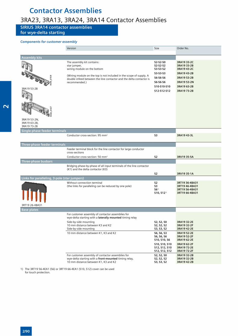
SIRIUS 3RA14 contactor assembliesfor wye-delta starting
SIRIUS 3RA14 contactor assembliesfor wye-delta starting
Components for customer assembly
Version Size Order No.
Assembly kits
3RA19 53-2B
3RA19 53-2N, 3RA19 63-2B, 3RA19 73-2B
The assembly kit contains: star jumper, wiring module on the bottom
(Wiring module on the top is not included in the scope of supply. A double infeed between the line contactor and the delta contactor is recommended.)
S2-S2-S0S2-S2-S2S3-S3-S2
3RA19 33-2C3RA19 33-2B3RA19 43-2C
S3-S3-S3 3RA19 43-2B
S6-S6-S6 3RA19 53-2B
S6-S6-S6 3RA19 53-2N
S10-S10-S10 3RA19 63-2B
S12-S12-S12 3RA19 73-2B
Single-phase feeder terminals Conductor cross-section: 95 mm2 S3 3RA19 43-3L
Three-phase feeder terminalsFeeder terminal block for the line contactor for large conductor cross-sections
Conductor cross-section: 50 mm2 S2 3RV19 35-5A
Three-phase busbarsBridging phase-by-phase of all input terminals of the line contactor (K1) and the delta contactor (K3)
S2 3RV19 35-1A
Links for paralleling, 3-pole (star jumpers)
3RT19 26-4BA31
Without connection terminal(the links for paralleling can be reduced by one pole)
S2S3S61)
S10, S121)
3RT19 36-4BA313RT19 46-4BA313RT19 56-4BA313RT19 66-4BA31
Base plates For customer assembly of contactor assemblies for wye-delta starting with a laterally mounted timing relay
Side-by-side mounting10 mm distance between K3 and K2Side-by-side mounting
S2, S2, S0 S2, S2, S2 S3, S3, S2
3RA19 32-2E3RA19 32-2F3RA19 42-2E
10 mm distance between K1, K3 and K2 S6, S6, S3 S6, S6, S6 S10, S10, S6
3RA19 52-2E3RA19 52-2F3RA19 62-2E
S10, S10, S10 S12, S12, S10 S12, S12, S12
3RA19 62-2F3RA19 72-2E3RA19 72-2F
For customer assembly of contactor assemblies for wye-delta starting with a front-mounted timing relay, 10 mm distance between K1, K3 and K2
S2, S2, S0 S2, S2, S2 S3, S3, S2
3RA19 32-2B3RA19 32-2B3RA19 42-2B
1) The 3RT19 56-4EA1 (S6) or 3RT19 66-4EA1 (S10, S12) cover can be used for touch protection.
Contactor Assemblies3RA23, 3RA13, 3RA24, 3RA14 Contactor Assemblies
2/90
2
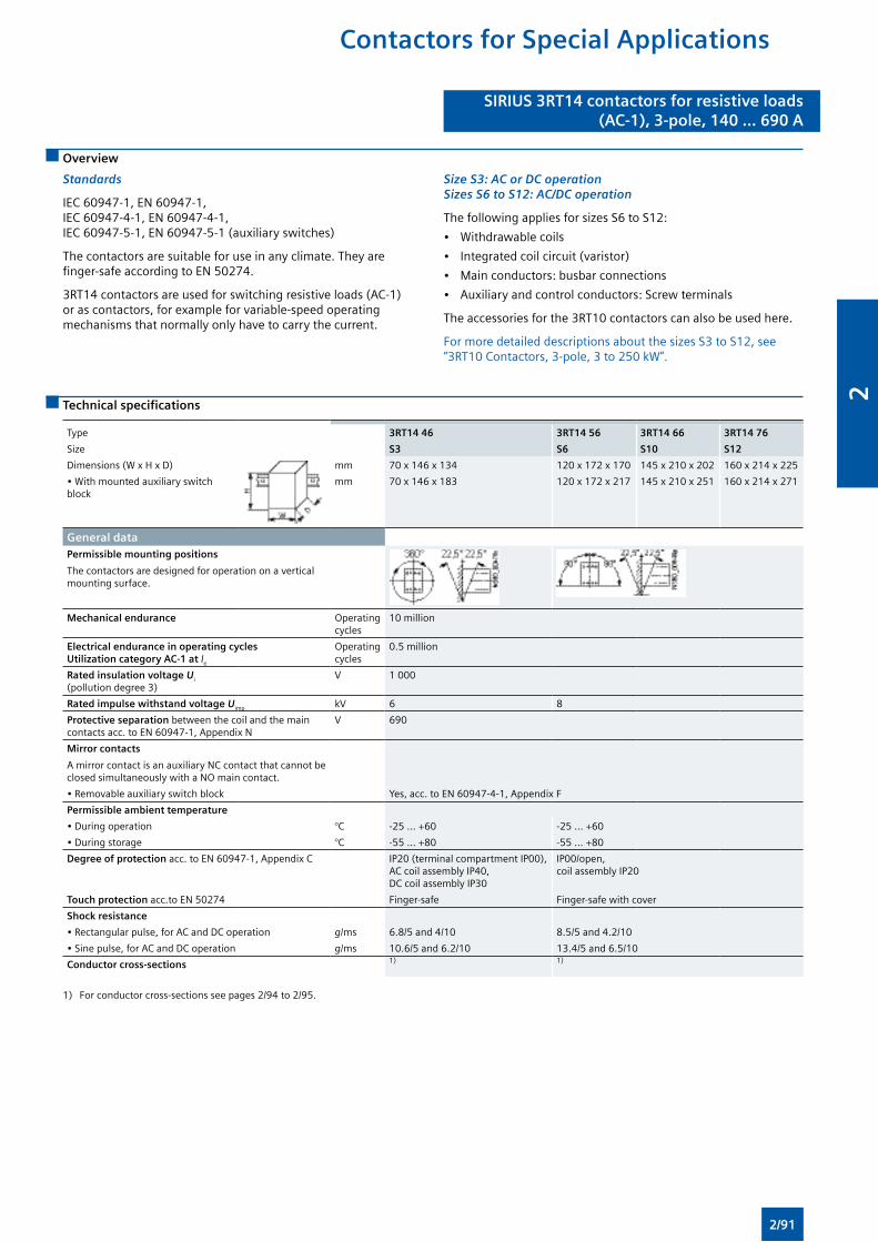
SIRIUS 3RT14 contactors for resistive loads(AC-1), 3-pole, 140 ... 690 A
SIRIUS 3RT14 contactors for resistive loads(AC-1), 3-pole, 140 ... 690 A
Overview
Standards
IEC 60947-1, EN 60947-1, IEC 60947-4-1, EN 60947-4-1, IEC 60947-5-1, EN 60947-5-1 (auxiliary switches)
The contactors are suitable for use in any climate. They are finger-safe according to EN 50274.
3RT14 contactors are used for switching resistive loads (AC-1) or as contactors, for example for variable-speed operating mechanisms that normally only have to carry the current.
Size S3: AC or DC operation Sizes S6 to S12: AC/DC operation
The following applies for sizes S6 to S12:
• Withdrawable coils
• Integrated coil circuit (varistor)
• Main conductors: busbar connections
• Auxiliary and control conductors: Screw terminals
The accessories for the 3RT10 contactors can also be used here.
For more detailed descriptions about the sizes S3 to S12, see “3RT10 Contactors, 3-pole, 3 to 250 kW”.
Technical specifications
Type 3RT14 46 3RT14 56 3RT14 66 3RT14 76
Size S3 S6 S10 S12
Dimensions (W x H x D) mm 70 x 146 x 134 120 x 172 x 170 145 x 210 x 202 160 x 214 x 225
• With mounted auxiliary switch block
mm 70 x 146 x 183 120 x 172 x 217 145 x 210 x 251 160 x 214 x 271
General dataPermissible mounting positions
The contactors are designed for operation on a vertical mounting surface.
Mechanical endurance Operating cycles
10 million
Electrical endurance in operating cycles Utilization category AC-1 at Ie
Operating cycles
0.5 million
Rated insulation voltage Ui (pollution degree 3)
V 1 000
Rated impulse withstand voltage Uimp kV 6 8
Protective separation between the coil and the main contacts acc. to EN 60947-1, Appendix N
V 690
Mirror contacts
A mirror contact is an auxiliary NC contact that cannot be closed simultaneously with a NO main contact.
• Removable auxiliary switch block Yes, acc. to EN 60947-4-1, Appendix F
Permissible ambient temperature
• During operation °C -25 ... +60 -25 ... +60
• During storage °C -55 ... +80 -55 ... +80
Degree of protection acc. to EN 60947-1, Appendix C IP20 (terminal compartment IP00), AC coil assembly IP40, DC coil assembly IP30
IP00/open, coil assembly IP20
Touch protection acc.to EN 50274 Finger-safe Finger-safe with cover
Shock resistance
• Rectangular pulse, for AC and DC operation g/ms 6.8/5 and 4/10 8.5/5 and 4.2/10
• Sine pulse, for AC and DC operation g/ms 10.6/5 and 6.2/10 13.4/5 and 6.5/10
Conductor cross-sections 1) 1)
1) For conductor cross-sections see pages 2/94 to 2/95.
Contactors for Special Applications
2/91
2
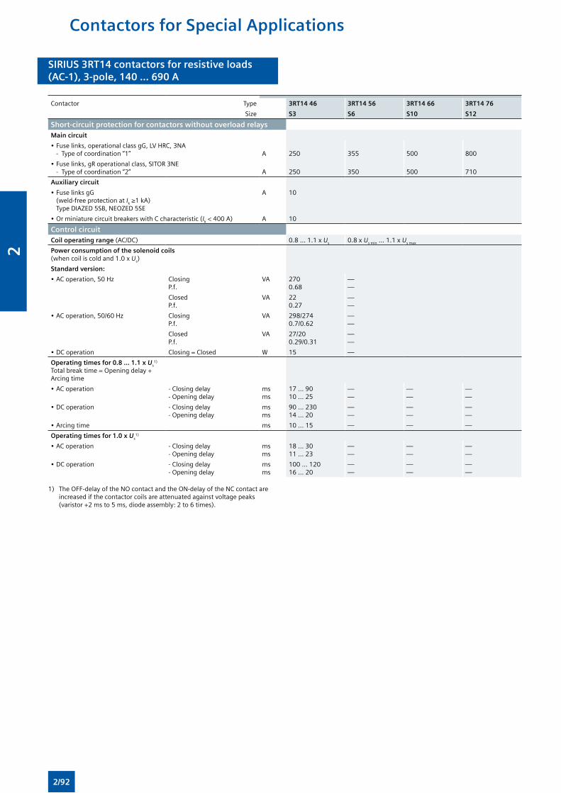
SIRIUS 3RT14 contactors for resistive loads(AC-1), 3-pole, 140 ... 690 A
SIRIUS 3RT14 contactors for resistive loads(AC-1), 3-pole, 140 ... 690 A
Contactor Type 3RT14 46 3RT14 56 3RT14 66 3RT14 76
Size S3 S6 S10 S12
Short-circuit protection for contactors without overload relaysMain circuit
• Fuse links, operational class gG, LV HRC, 3NA - Type of coordination “1”
A
250
355
500
800
• Fuse links, gR operational class, SITOR 3NE - Type of coordination “2”
A
250
350
500
710
Auxiliary circuit
• Fuse links gG (weld-free protection at Ik ≥1 kA) Type DIAZED 5SB, NEOZED 5SE
A 10
• Or miniature circuit breakers with C characteristic (Ik < 400 A) A 10
Control circuitCoil operating range (AC/DC) 0.8 ... 1.1 x Us 0.8 x Us min ... 1.1 x Us max
Power consumption of the solenoid coils (when coil is cold and 1.0 x Us)
Standard version:
• AC operation, 50 Hz ClosingP.f.
VA 2700.68
——
ClosedP.f.
VA 220.27
——
• AC operation, 50/60 Hz ClosingP.f.
VA 298/2740.7/0.62
——
ClosedP.f.
VA 27/200.29/0.31
——
• DC operation Closing = Closed W 15 —
Operating times for 0.8 ... 1.1 x Us1)
Total break time = Opening delay + Arcing time
• AC operation - Closing delay- Opening delay
msms
17 ... 9010 ... 25
——
——
——
• DC operation - Closing delay- Opening delay
msms
90 ... 23014 ... 20
——
——
——
• Arcing time ms 10 ... 15 — — —
Operating times for 1.0 x Us1)
• AC operation - Closing delay- Opening delay
msms
18 ... 3011 ... 23
——
——
——
• DC operation - Closing delay- Opening delay
msms
100 ... 12016 ... 20
——
——
——
1) The OFF-delay of the NO contact and the ON-delay of the NC contact are increased if the contactor coils are attenuated against voltage peaks (varistor +2 ms to 5 ms, diode assembly: 2 to 6 times).
Contactors for Special Applications
2/92
2

SIRIUS 3RT14 contactors for resistive loads(AC-1), 3-pole, 140 ... 690 A
SIRIUS 3RT14 contactors for resistive loads(AC-1), 3-pole, 140 ... 690 A
Contactor Type 3RT14 46 3RT14 56 3RT14 66 3RT14 76
Size S3 S6 S10 S12
Control circuitOperating times (Total break time = Opening delay + Arcing time)
• Conventional operating mechanisms
- For 0.8 x Us min ... 1.1 x Us max Closing delayOpening delay
msms
20 ... 9540 ... 60
30 ... 9540 ... 80
45 ... 10060 ... 100
- For Us min ... Us max Closing delayOpening delay
msms
25 ... 5040 ... 60
35 ... 5050 ... 80
50 ... 7070 ... 100
• Solid-state operating mechanism, actuated via A1/A2
- For 0.8 x Us min ... 1.1 x Us max Closing delayOpening delay
msms
95 ... 13580 ... 90
105 ... 14580 ... 200
120 ... 15080 ... 100
- For Us min ... Us max Closing delayOpening delay
msms
100 ... 12080 ... 90
110 ... 13080 ... 100
125 ... 15080 ... 100
• Solid-state operating mechanism, actuated via PLC input
- For 0.8 x Us min ... 1.1 x Us max Closing delayOpening delay
msms
35 ... 7580 ... 90
45 ... 8080 ... 100
60 ... 9080 ... 100
- For Us min ... Us max Closing delayOpening delay
msms
40 ... 6080 ... 90
50 ... 6580 ... 100
65 ... 8080 ... 100
• Arcing time ms 10 ... 15 10 ... 15 10 ... 15
Contactor Type 3RT14 46 3RT14 56 3RT14 66 3RT14 76
Size S3 S6 S10 S12
Main circuit
AC capacityUtilization category AC-1, switching resistive loads
• Rated operational currents Ie At 40 °C up to 690 VAt 60 °C up to 690 V
At 1000 V
AAA
14013060
275250100
400380150
6906501)
250
• Rated power for AC loads2) with p.f.= 0.95 (at 60 °C)
At 415 V kW 86 165 250 430
• Minimum conductor cross-section for loads with Ie
At 40 °CAt 60 °C
mm2
mm2
5050
2 x 70120
240240
2 x 2402 x 240
Utilization categories AC-2 and AC-3With an electrical endurance of 1.3 million operating cycles
• Rated operational current Ie Up to 690 V A 44 97 138 170
• Rated power for slipring or squirrel-cage motors at 50 and 60 Hz (at 60 °C)
At 230 V400 V500 V690 V
kWkWkWkW
12.72229.938.2
30555590
377590132
5590110160
Power loss per conducting path At Ie/AC-1 W 12.5 20 27 55
Switching frequencySwitching frequency z in operating cycles/hour
• Contactors without overload relays No-load switching frequency AC
No-load switching frequency DC
1/h
1/h
5 000
1 000
• Rated operation Acc. to AC-1 (AC/DC)Acc. to AC-3 (AC/DC)
1/h1/h
6501000
Dependence of the switching frequency z’ on the operational current I’ and operational voltage U’:z’ = z ·(Ie/I’) ·(400 V/U’)1.5 ·1/h.
1) 600 A for 3RT14 76-N contactor.
2) Industrial furnaces and electric heaters with resistance heating, etc. (increased power consumption on heating up has been taken into account).
Contactors for Special Applications
2/93
2
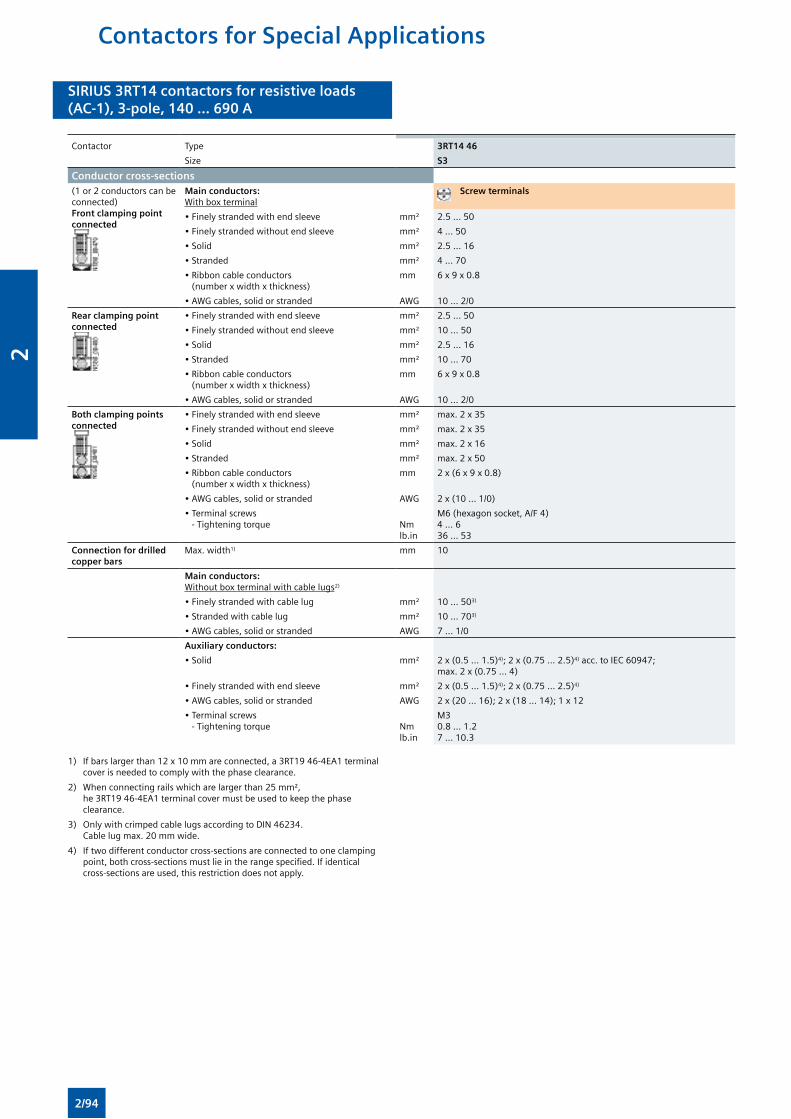
SIRIUS 3RT14 contactors for resistive loads(AC-1), 3-pole, 140 ... 690 A
SIRIUS 3RT14 contactors for resistive loads(AC-1), 3-pole, 140 ... 690 A
Contactor Type 3RT14 46
Size S3
Conductor cross-sections(1 or 2 conductors can be connected)Front clamping point connected
Main conductors: With box terminal
Screw terminals
• Finely stranded with end sleeve mm² 2.5 ... 50
• Finely stranded without end sleeve mm² 4 ... 50
• Solid mm² 2.5 ... 16
• Stranded mm² 4 ... 70
• Ribbon cable conductors (number x width x thickness)
mm 6 x 9 x 0.8
• AWG cables, solid or stranded AWG 10 ... 2/0
Rear clamping point connected
• Finely stranded with end sleeve mm² 2.5 ... 50
• Finely stranded without end sleeve mm² 10 ... 50
• Solid mm² 2.5 ... 16
• Stranded mm² 10 ... 70
• Ribbon cable conductors (number x width x thickness)
mm 6 x 9 x 0.8
• AWG cables, solid or stranded AWG 10 ... 2/0
Both clamping points connected
• Finely stranded with end sleeve mm² max. 2 x 35
• Finely stranded without end sleeve mm² max. 2 x 35
• Solid mm² max. 2 x 16
• Stranded mm² max. 2 x 50
• Ribbon cable conductors (number x width x thickness)
mm 2 x (6 x 9 x 0.8)
• AWG cables, solid or stranded AWG 2 x (10 ... 1/0)
• Terminal screws - Tightening torque
Nmlb.in
M6 (hexagon socket, A/F 4)4 ... 636 ... 53
Connection for drilled copper bars
Max. width1) mm 10
Main conductors: Without box terminal with cable lugs2)
• Finely stranded with cable lug mm² 10 ... 503)
• Stranded with cable lug mm² 10 ... 703)
• AWG cables, solid or stranded AWG 7 ... 1/0
Auxiliary conductors:
• Solid mm² 2 x (0.5 ... 1.5)4); 2 x (0.75 ... 2.5)4) acc. to IEC 60947; max. 2 x (0.75 ... 4)
• Finely stranded with end sleeve mm² 2 x (0.5 ... 1.5)4); 2 x (0.75 ... 2.5)4)
• AWG cables, solid or stranded AWG 2 x (20 ... 16); 2 x (18 ... 14); 1 x 12
• Terminal screws - Tightening torque
Nmlb.in
M30.8 ... 1.27 ... 10.3
1) If bars larger than 12 x 10 mm are connected, a 3RT19 46-4EA1 terminal cover is needed to comply with the phase clearance.
2) When connecting rails which are larger than 25 mm², he 3RT19 46-4EA1 terminal cover must be used to keep the phase clearance.
3) Only with crimped cable lugs according to DIN 46234. Cable lug max. 20 mm wide.
4) If two different conductor cross-sections are connected to one clamping point, both cross-sections must lie in the range specified. If identical cross-sections are used, this restriction does not apply.
Contactors for Special Applications
2/94
2
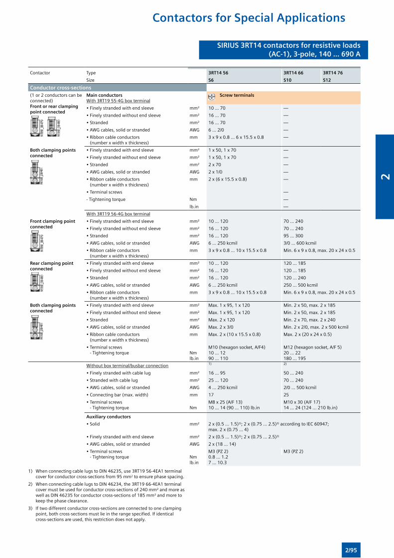
SIRIUS 3RT14 contactors for resistive loads(AC-1), 3-pole, 140 ... 690 A
SIRIUS 3RT14 contactors for resistive loads(AC-1), 3-pole, 140 ... 690 A
Contactor Type 3RT14 56 3RT14 66 3RT14 76
Size S6 S10 S12
Conductor cross-sections (1 or 2 conductors can be connected)Front or rear clamping point connected
Main conductors With 3RT19 55-4G box terminal
Screw terminals
• Finely stranded with end sleeve mm² 10 ... 70 —
• Finely stranded without end sleeve mm² 16 ... 70 —
• Stranded mm² 16 ... 70 —
• AWG cables, solid or stranded AWG 6 ... 2/0 —
• Ribbon cable conductors (number x width x thickness)
mm 3 x 9 x 0.8 ... 6 x 15.5 x 0.8 —
Both clamping points connected
• Finely stranded with end sleeve mm² 1 x 50, 1 x 70 —
• Finely stranded without end sleeve mm² 1 x 50, 1 x 70 —
• Stranded mm² 2 x 70 —
• AWG cables, solid or stranded AWG 2 x 1/0 —
• Ribbon cable conductors (number x width x thickness)
mm 2 x (6 x 15.5 x 0.8) —
• Terminal screws —
- Tightening torque Nm —
lb.in —
With 3RT19 56-4G box terminal
Front clamping point connected
• Finely stranded with end sleeve mm² 10 ... 120 70 ... 240
• Finely stranded without end sleeve mm² 16 ... 120 70 ... 240
• Stranded mm² 16 ... 120 95 ... 300
• AWG cables, solid or stranded AWG 6 ... 250 kcmil 3/0 ... 600 kcmil
• Ribbon cable conductors (number x width x thickness)
mm 3 x 9 x 0.8 ... 10 x 15.5 x 0.8 Min. 6 x 9 x 0.8, max. 20 x 24 x 0.5
Rear clamping point connected
• Finely stranded with end sleeve mm² 10 ... 120 120 ... 185
• Finely stranded without end sleeve mm² 16 ... 120 120 ... 185
• Stranded mm² 16 ... 120 120 ... 240
• AWG cables, solid or stranded AWG 6 ... 250 kcmil 250 ... 500 kcmil
• Ribbon cable conductors (number x width x thickness)
mm 3 x 9 x 0.8 ... 10 x 15.5 x 0.8 Min. 6 x 9 x 0.8, max. 20 x 24 x 0.5
Both clamping points connected
• Finely stranded with end sleeve mm² Max. 1 x 95, 1 x 120 Min. 2 x 50, max. 2 x 185
• Finely stranded without end sleeve mm² Max. 1 x 95, 1 x 120 Min. 2 x 50, max. 2 x 185
• Stranded mm² Max. 2 x 120 Min. 2 x 70, max. 2 x 240
• AWG cables, solid or stranded AWG Max. 2 x 3/0 Min. 2 x 2/0, max. 2 x 500 kcmil
• Ribbon cable conductors (number x width x thickness)
mm Max. 2 x (10 x 15.5 x 0.8) Max. 2 x (20 x 24 x 0.5)
• Terminal screws - Tightening torque
Nmlb.in
M10 (hexagon socket, A/F4)10 ... 1290 ... 110
M12 (hexagon socket, A/F 5)20 ... 22180 ... 195
Without box terminal/busbar connection 1) 2)
• Finely stranded with cable lug mm² 16 ... 95 50 ... 240
• Stranded with cable lug mm² 25 ... 120 70 ... 240
• AWG cables, solid or stranded AWG 4 ... 250 kcmil 2/0 ... 500 kcmil
• Connecting bar (max. width) mm 17 25
• Terminal screws - Tightening torque
Nm
M8 x 25 (A/F 13)10 ... 14 (90 ... 110) lb.in
M10 x 30 (A/F 17)14 ... 24 (124 ... 210 lb.in)
Auxiliary conductors
• Solid mm² 2 x (0.5 ... 1.5)3); 2 x (0.75 ... 2.5)3) according to IEC 60947; max. 2 x (0.75 ... 4)
• Finely stranded with end sleeve mm² 2 x (0.5 ... 1.5)3); 2 x (0.75 ... 2.5)3)
• AWG cables, solid or stranded AWG 2 x (18 ... 14)
• Terminal screws - Tightening torque
Nmlb.in
M3 (PZ 2)0.8 ... 1.27 ... 10.3
M3 (PZ 2)
1) When connecting cable lugs to DIN 46235, use 3RT19 56-4EA1 terminal cover for conductor cross-sections from 95 mm2 to ensure phase spacing.
2) When connecting cable lugs to DIN 46234, the 3RT19 66-4EA1 terminal cover must be used for conductor cross-sections of 240 mm² and more as well as DIN 46235 for conductor cross-sections of 185 mm² and more to keep the phase clearance.
3) If two different conductor cross-sections are connected to one clamping point, both cross-sections must lie in the range specified. If identical cross-sections are used, this restriction does not apply.
Contactors for Special Applications
2/95
2
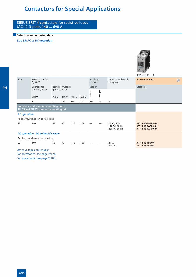
SIRIUS 3RT14 contactors for resistive loads(AC-1), 3-pole, 140 ... 690 A
SIRIUS 3RT14 contactors for resistive loads(AC-1), 3-pole, 140 ... 690 A
Selection and ordering data
Size S3: AC or DC operation
3RT14 46-1A . . 0
Size Rated data AC-1, Tu: 40 °C
Auxiliary contacts
Rated control supply voltage Us
Screw terminals
Operational current Ie up to
Rating of AC loads (p f. = 0.95) at
Version Order No.
690 V 230 V 415 V 500 V 690 V
A kW kW kW kW NO NC V
For screw and snap-on mounting onto TH 35 and TH 75 standard mounting rail
AC operation
Auxiliary switches can be retrofitted
S3 140 53 92 115 159 — — 24 AC, 50 Hz110 AC, 50 Hz230 AC, 50 Hz
3RT14 46-1AB00-8K3RT14 46-1AF00-8K3RT14 46-1AP00-8K
DC operation · DC solenoid system
Auxiliary switches can be retrofitted
S3 140 53 92 115 159 — — 24 DC220 DC
3RT14 46-1BB403RT14 46-1BM40
Other voltages on request.
For accessories, see page 2/176.
For spare parts, see page 2/183.
Contactors for Special Applications
2/96
2
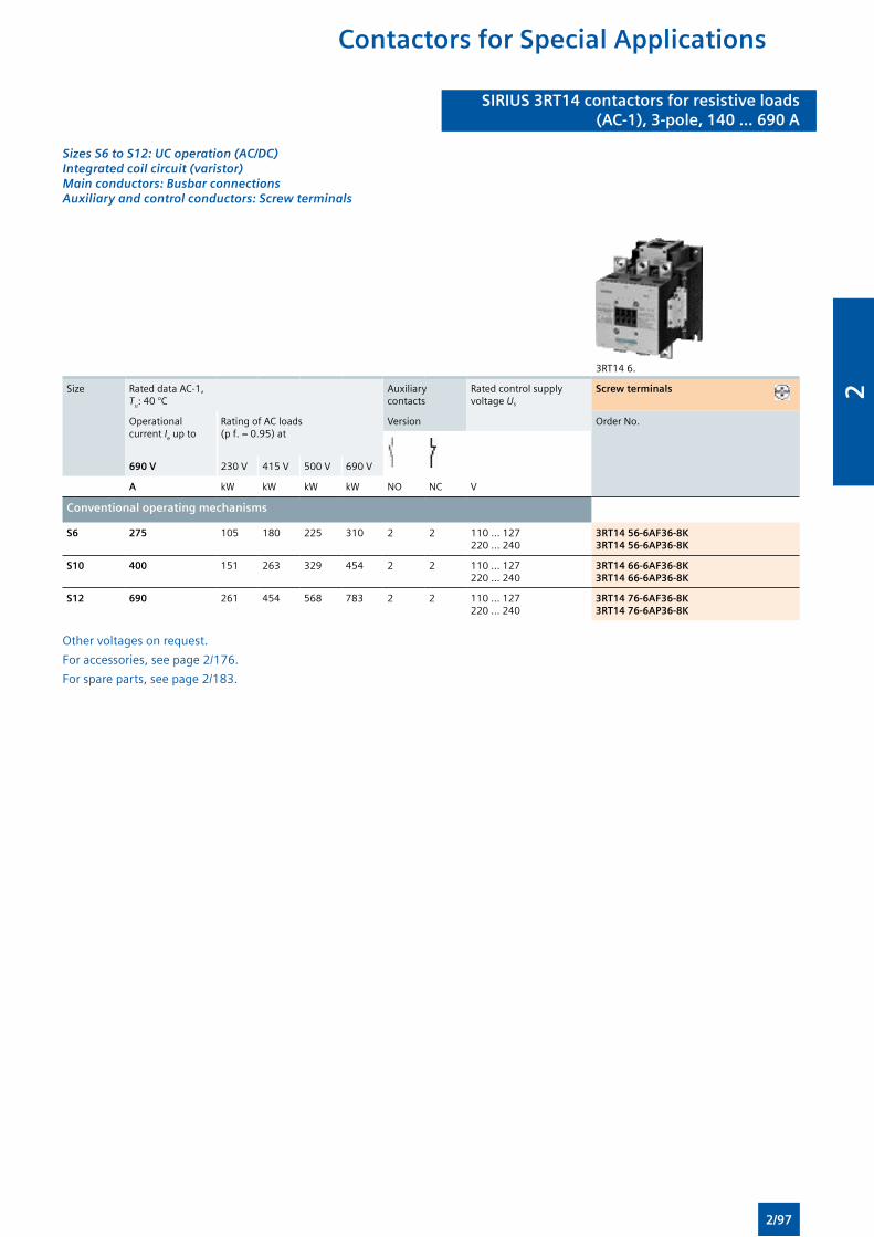
Sizes S6 to S12: UC operation (AC/DC) Integrated coil circuit (varistor)Main conductors: Busbar connections Auxiliary and control conductors: Screw terminals
3RT14 6.
Size Rated data AC-1, Tu: 40 °C
Auxiliary contacts
Rated control supply voltage Us
Screw terminals
Operational current Ie up to
Rating of AC loads (p f. = 0.95) at
Version Order No.
690 V 230 V 415 V 500 V 690 V
A kW kW kW kW NO NC V
Conventional operating mechanisms
S6 275 105 180 225 310 2 2 110 ... 127220 ... 240
3RT14 56-6AF36-8K3RT14 56-6AP36-8K
S10 400 151 263 329 454 2 2 110 ... 127220 ... 240
3RT14 66-6AF36-8K3RT14 66-6AP36-8K
S12 690 261 454 568 783 2 2 110 ... 127220 ... 240
3RT14 76-6AF36-8K3RT14 76-6AP36-8K
Other voltages on request.
For accessories, see page 2/176.
For spare parts, see page 2/183.
SIRIUS 3RT14 contactors for resistive loads(AC-1), 3-pole, 140 ... 690 A
SIRIUS 3RT14 contactors for resistive loads(AC-1), 3-pole, 140 ... 690 A
Contactors for Special Applications
2/97
2
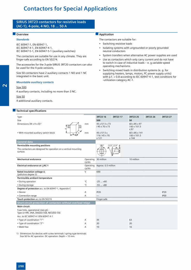
SIRIUS 3RT23 contactors for resistive loads(AC-1), 4-pole, 4 NO, 18 ... 50 A
SIRIUS 3RT23 contactors for resistive loads(AC-1), 4-pole, 4 NO, 18 ... 50 A
Overview
Standards
IEC 60947-1, EN 60947-1, IEC 60947-4-1, EN 60947-4-1, IEC 60947-5-1, EN 60947-5-1 (auxiliary switches)
The contactors are suitable for use in any climate. They are finger-safe according to EN 50274.
The accessories for the 3-pole SIRIUS 3RT20 contactors can also be used for the 4-pole versions.
Size S0 contactors have 2 auxiliary contacts 1 NO and 1 NC integrated in the basic unit.
Mountable auxiliary contacts
Size S00
4 auxiliary contacts, including no more than 3 NC.
Size S0
4 additional auxiliary contacts.
Application
The contactors are suitable for:
• Switching resistive loads
• Isolating systems with ungrounded or poorly grounded neutral conductors
• System transfers when alternative AC power supplies are used
• Use as contactors which only carry current and do not have to switch in case of inductive loads – e. g.variable-speed operating mechanisms
• Switching mixed loads in distribution systems (e. g. for supplying heaters, lamps, motors, PC power supply units) with p.f. > 0.8 according to IEC 60947-4-1, test conditions for -utilization category AC-1.
Technical specifications
Type 3RT23 16 3RT23 17 3RT23 25 3RT23 26 3RT23 27
Size S00 S0
Dimensions (W x H x D)1) mm 45 x 57.5 x 73 / 45 x 70 x 73
60 x 85 x 97 / 60 x 101.5 x 97
• With mounted auxiliary switch block mm 45 x 57.5 x 116 / 45 x 70 x 121
60 x 85 x 141 / 60 x 101.5 x 144
General dataPermissible mounting positions
The contactors are designed for operation on a vertical mounting surface.
Mechanical endurance Operating cycles
30 million 10 million
Electrical endurance at Ie/AC-1 Operating cycles
Approx. 0.5 million
Rated insulation voltage Ui (pollution degree 3)
V 690
Permissible ambient temperature
• During operation °C -25 ... +60
• During storage °C -55 ... +80
Degree of protection acc. to EN 60947-1, Appendix C
• Device A IP20 IP20
• Connection range A — IP00
Touch protection acc.to EN 50274 Finger-safe
Short-circuit protection of contactors without overload relaysMain circuit
Fuse links, operational class gG : Type LV HRC 3NA, DIAZED 5SB, NEOZED 5SE
Acc. to IEC 60947-4-1/EN 60947-4-1
• Type of coordination “1”1) A 35 63
• Type of coordination “2”1) A 20 20
• Weld-free A 10 16
1) Dimensions for devices with screw terminals / spring-type terminals Size S0 for AC operation. DC operation: Depth + 10 mm.
Contactors for Special Applications
2/98
2
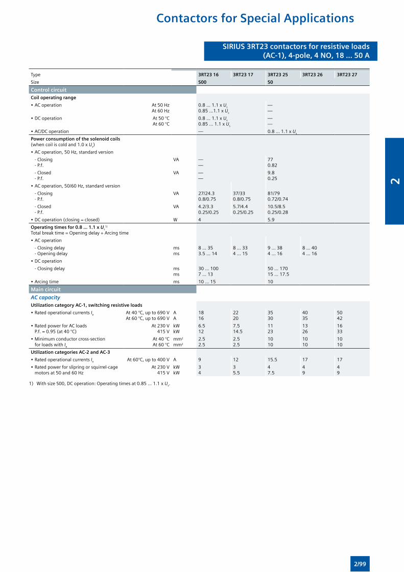
SIRIUS 3RT23 contactors for resistive loads(AC-1), 4-pole, 4 NO, 18 ... 50 A
SIRIUS 3RT23 contactors for resistive loads(AC-1), 4-pole, 4 NO, 18 ... 50 A
Type 3RT23 16 3RT23 17 3RT23 25 3RT23 26 3RT23 27
Size S00 S0
Control circuitCoil operating range
• AC operation At 50 HzAt 60 Hz
0.8 ... 1.1 x Us
0.85 ...1.1 x Us
——
• DC operation At 50 °CAt 60 °C
0.8 ... 1.1 x Us
0.85 ... 1.1 x Us
——
• AC/DC operation — 0.8 ... 1.1 x Us
Power consumption of the solenoid coils (when coil is cold and 1.0 x Us)
• AC operation, 50 Hz, standard version
- Closing - P.f.
VA ——
770.82
- Closed - P.f.
VA ——
9.80.25
• AC operation, 50/60 Hz, standard version
- Closing - P.f.
VA 27/24.30.8/0.75
37/330.8/0.75
81/790.72/0.74
- Closed - P.f.
VA 4.2/3.30.25/0.25
5.7/4.40.25/0.25
10.5/8.50.25/0.28
• DC operation (closing = closed) W 4 5.9
Operating times for 0.8 ... 1.1 x Us1)
Total break time = Opening delay + Arcing time
• AC operation
- Closing delay - Opening delay
msms
8 ... 353.5 ... 14
8 ... 334 ... 15
9 ... 384 ... 16
8 ... 404 ... 16
• DC operation
- Closing delay msms
30 ... 1007 ... 13
50 ... 17015 ... 17.5
• Arcing time ms 10 ... 15 10
Main circuit
AC capacityUtilization category AC-1, switching resistive loads
• Rated operational currents Ie At 40 °C, up to 690 VAt 60 °C, up to 690 V
AA
1816
2220
3530
4035
5042
• Rated power for AC loads P.f. = 0.95 (at 40 °C)
At 230 V415 V
kWkW
6.512
7.514.5
1123
1326
1633
• Minimum conductor cross-section for loads with Ie
At 40 °CAt 60 °C
mm2
mm2
2.52.5
2.52.5
1010
1010
1010
Utilization categories AC-2 and AC-3
• Rated operational currents Ie At 60°C, up to 400 V A 9 12 15.5 17 17
• Rated power for slipring or squirrel-cage motors at 50 and 60 Hz
At 230 V415 V
kWkW
34
35.5
47.5
49
49
1) With size S00, DC operation: Operating times at 0.85 ... 1.1 x Us.
Contactors for Special Applications
2/99
2
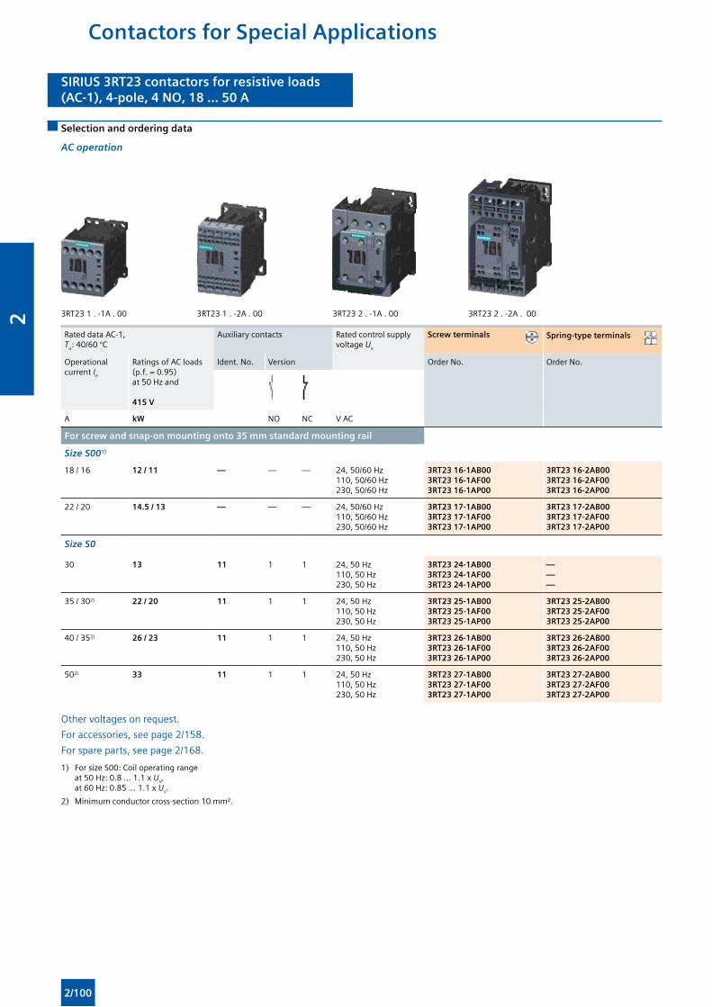
SIRIUS 3RT23 contactors for resistive loads(AC-1), 4-pole, 4 NO, 18 ... 50 A
SIRIUS 3RT23 contactors for resistive loads(AC-1), 4-pole, 4 NO, 18 ... 50 A
Selection and ordering data
AC operation
3RT23 1 . -1A . 00 3RT23 1 . -2A . 00 3RT23 2 . -1A . 00 3RT23 2 . -2A . 00
Rated data AC-1, Tu: 40/60 °C
Auxiliary contacts Rated control supply voltage Us
Screw terminals Spring-type terminals
Operational current Ie
Ratings of AC loads (p.f. = 0.95) at 50 Hz and
415 V
Ident. No. Version Order No. Order No.
A kW NO NC V AC
For screw and snap-on mounting onto 35 mm standard mounting rail
Size S001)
18 / 16 12 / 11 — — — 24, 50/60 Hz110, 50/60 Hz230, 50/60 Hz
3RT23 16-1AB003RT23 16-1AF003RT23 16-1AP00
3RT23 16-2AB003RT23 16-2AF003RT23 16-2AP00
22 / 20 14.5 / 13 — — — 24, 50/60 Hz110, 50/60 Hz230, 50/60 Hz
3RT23 17-1AB003RT23 17-1AF003RT23 17-1AP00
3RT23 17-2AB003RT23 17-2AF003RT23 17-2AP00
Size S0
30 13 11 1 1 24, 50 Hz110, 50 Hz230, 50 Hz
3RT23 24-1AB003RT23 24-1AF003RT23 24-1AP00
———
35 / 302) 22 / 20 11 1 1 24, 50 Hz110, 50 Hz230, 50 Hz
3RT23 25-1AB003RT23 25-1AF003RT23 25-1AP00
3RT23 25-2AB003RT23 25-2AF003RT23 25-2AP00
40 / 352) 26 / 23 11 1 1 24, 50 Hz110, 50 Hz230, 50 Hz
3RT23 26-1AB003RT23 26-1AF003RT23 26-1AP00
3RT23 26-2AB003RT23 26-2AF003RT23 26-2AP00
502) 33 11 1 1 24, 50 Hz110, 50 Hz230, 50 Hz
3RT23 27-1AB003RT23 27-1AF003RT23 27-1AP00
3RT23 27-2AB003RT23 27-2AF003RT23 27-2AP00
Other voltages on request.
For accessories, see page 2/158.
For spare parts, see page 2/168.
1) For size S00: Coil operating range at 50 Hz: 0.8 ... 1.1 x Us, at 60 Hz: 0.85 ... 1.1 x Us.
2) Minimum conductor cross-section 10 mm².
Contactors for Special Applications
2/100
2
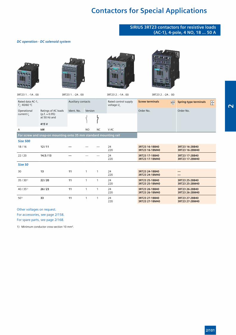
SIRIUS 3RT23 contactors for resistive loads(AC-1), 4-pole, 4 NO, 18 ... 50 A
SIRIUS 3RT23 contactors for resistive loads(AC-1), 4-pole, 4 NO, 18 ... 50 A
DC operation · DC solenoid system
3RT23 1 . -1A . 00 3RT23 1 . -2A . 00 3RT23 2 . -1A . 00 3RT23 2 . -2A . 00
Rated data AC-1, Tu: 40/60 °C
Auxiliary contacts Rated control supply voltage Us
Screw terminals Spring-type terminals
Operational current Ie
Ratings of AC loads (p.f. = 0.95) at 50 Hz and
415 V
Ident. No. Version Order No. Order No.
A kW NO NC V AC
For screw and snap-on mounting onto 35 mm standard mounting rail
Size S00
18 / 16 12 / 11 — — — 24220
3RT23 16-1BB403RT23 16-1BM40
3RT23 16-2BB403RT23 16-2BM40
22 / 20 14.5 / 13 — — — 24220
3RT23 17-1BB403RT23 17-1BM40
3RT23 17-2BB403RT23 17-2BM40
Size S0
30 13 11 1 1 24220
3RT23 24-1BB403RT23 24-1BM40
——
35 / 301) 22 / 20 11 1 1 24220
3RT23 25-1BB403RT23 25-1BM40
3RT23 25-2BB403RT23 25-2BM40
40 / 351) 26 / 23 11 1 1 24220
3RT23 26-1BB403RT23 26-1BM40
3RT23 26-2BB403RT23 26-2BM40
501) 33 11 1 1 24220
3RT23 27-1BB403RT23 27-1BM40
3RT23 27-2BB403RT23 27-2BM40
Other voltages on request.
For accessories, see page 2/158.
For spare parts, see page 2/168.
1) Minimum conductor cross-section 10 mm².
Contactors for Special Applications
2/101
2
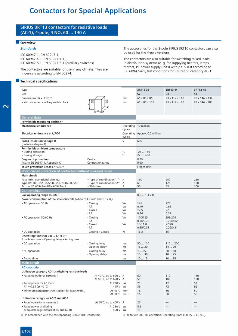
SIRIUS 3RT13 contactors for resistive loads(AC-1), 4-pole, 4 NO, 60 ... 140 A
SIRIUS 3RT13 contactors for resistive loads(AC-1), 4-pole, 4 NO, 60 ... 140 A
Overview
Standards
IEC 60947-1, EN 60947-1, IEC 60947-4-1, EN 60947-4-1, IEC 60947-5-1, EN 60947-5-1 (auxiliary switches)
The contactors are suitable for use in any climate. They are finger-safe according to EN 50274.
The accessories for the 3-pole SIRIUS 3RT10 contactors can also be used for the 4-pole versions.
The contactors are also suitable for switching mixed loads in distribution systems (e. g. for supplying heaters, lamps, motors, PC power supply units) with p.f. > 0.8 according to IEC 60947-4-1, test conditions for utilization category AC-1.
Technical specifications
Type 3RT13 36 3RT13 44 3RT13 46
Size S2 S3 S3
Dimensions (W x H x D)1) mm 61 x 85 x 86 73 x 112 x 110 93 x 146 x 134
• With mounted auxiliary switch block mm 61 x 85 x 135 73 x 112 x 160 93 x 146 x 183
General dataPermissible mounting position1)
Mechanical endurance Operating cycles
10 million
Electrical endurance at Ie/AC-1 Operating cycles
Approx. 0.5 million
Rated insulation voltage Ui (pollution degree 3)
V 690
Permissible ambient temperature• During operation• During storage
°C°C
-25 ... +60-55 ... +80
Degree of protection Acc. to EN 60947-1, Appendix C
DeviceConnection range
IP20IP00
Touch protection acc.to EN 50274 Finger-safe
Short-circuit protection of contactors without overload relaysMain circuit
Fuse links, operational class gG Type LV HRC, 3NA, DIAZED, 5SB, NEOZED, 5SEAcc. to IEC 60947-4-1/EN 60947-4-1
• Type of coordination “1”1)
• Type of coordination “2”1)
• Weld-free
AAA
1606350
25012563
250160100
Control circuitCoil operating range (AC/DC) 0.8 ... 1.1 x Us
Power consumption of the solenoid coils (when coil is cold and 1.0 x Us)
• AC operation, 50 Hz - Closing- P.f.- Closed- P.f.
VAVAVAVA
1450.7912.50.36
2700.68220.27
• AC operation, 50/60 Hz - Closing- P.f.- Closed- P.f.
VA VA
170/1550.76/0.7215/11.80.35/0.38
298/2740.72/0.6227/200.29/0.31
• DC operation - Closing = Closed W 13.3 15
Operating times for 0.8 ... 1.1 x Us2)
Total break time = Opening delay + Arcing time
• DC operation - Closing delay- Opening delay
msms
50 ... 11015 ... 30
110 ... 20014 ... 20
• AC operation - Closing delay- Opening delay
msms
4 ... 3510 ... 30
20 ... 5010 ... 25
• Arcing time ms 10 ... 15 10 ... 15
Main circuitAC capacity Utilization category AC-1, switching resistive loads
• Rated operational currents Ie At 40 °C, up to 690 VAt 60 °C, up to 690 V
AA
6055
110100
140120
• Rated power for AC loads P.f. = 0.95 (at 40 °C)
At 230 V415 V
kWkW
2339
4272
5392
• Minimum conductor cross-section for loads with Ie At 40 °CAt 60 °C
mm²mm²
1616
5050
5050
Utilization categories AC-2 and AC-3
• Rated operational currents Ie At 60°C, up to 400 V A 26 — —
• Rated power of slipring or squirrel-cage motors at 50 and 60 Hz
At 230 V400 V
kWkW
5.511
——
——
1) In accordance with the corresponding 3-pole 3RT1 contactors. 2) With size S00, DC operation: Operating times at 0.85 ... 1.1 x Us.
Contactors for Special Applications
2/102
2
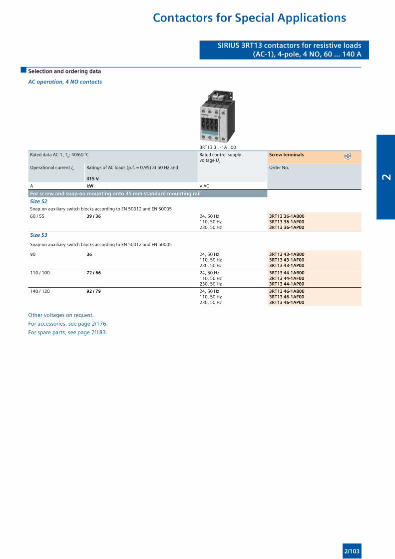
SIRIUS 3RT13 contactors for resistive loads(AC-1), 4-pole, 4 NO, 60 ... 140 A
SIRIUS 3RT13 contactors for resistive loads(AC-1), 4-pole, 4 NO, 60 ... 140 A
Selection and ordering data
AC operation, 4 NO contacts
3RT13 3 . -1A . 00
Rated data AC-1, Tu: 40/60 °C Rated control supply voltage Us
Screw terminals
Operational current Ie Ratings of AC loads (p.f. = 0.95) at 50 Hz and
415 V
Order No.
A kW V AC
For screw and snap-on mounting onto 35 mm standard mounting rail
Size S2Snap-on auxiliary switch blocks according to EN 50012 and EN 50005
60 / 55 39 / 36 24, 50 Hz110, 50 Hz230, 50 Hz
3RT13 36-1AB003RT13 36-1AF003RT13 36-1AP00
Size S3
Snap-on auxiliary switch blocks according to EN 50012 and EN 50005
90 36 24, 50 Hz110, 50 Hz230, 50 Hz
3RT13 43-1AB003RT13 43-1AF003RT13 43-1AP00
110 / 100 72 / 66 24, 50 Hz110, 50 Hz230, 50 Hz
3RT13 44-1AB003RT13 44-1AF003RT13 44-1AP00
140 / 120 92 / 79 24, 50 Hz110, 50 Hz 230, 50 Hz
3RT13 46-1AB003RT13 46-1AF003RT13 46-1AP00
Other voltages on request.
For accessories, see page 2/176.
For spare parts, see page 2/183.
Contactors for Special Applications
2/103
2
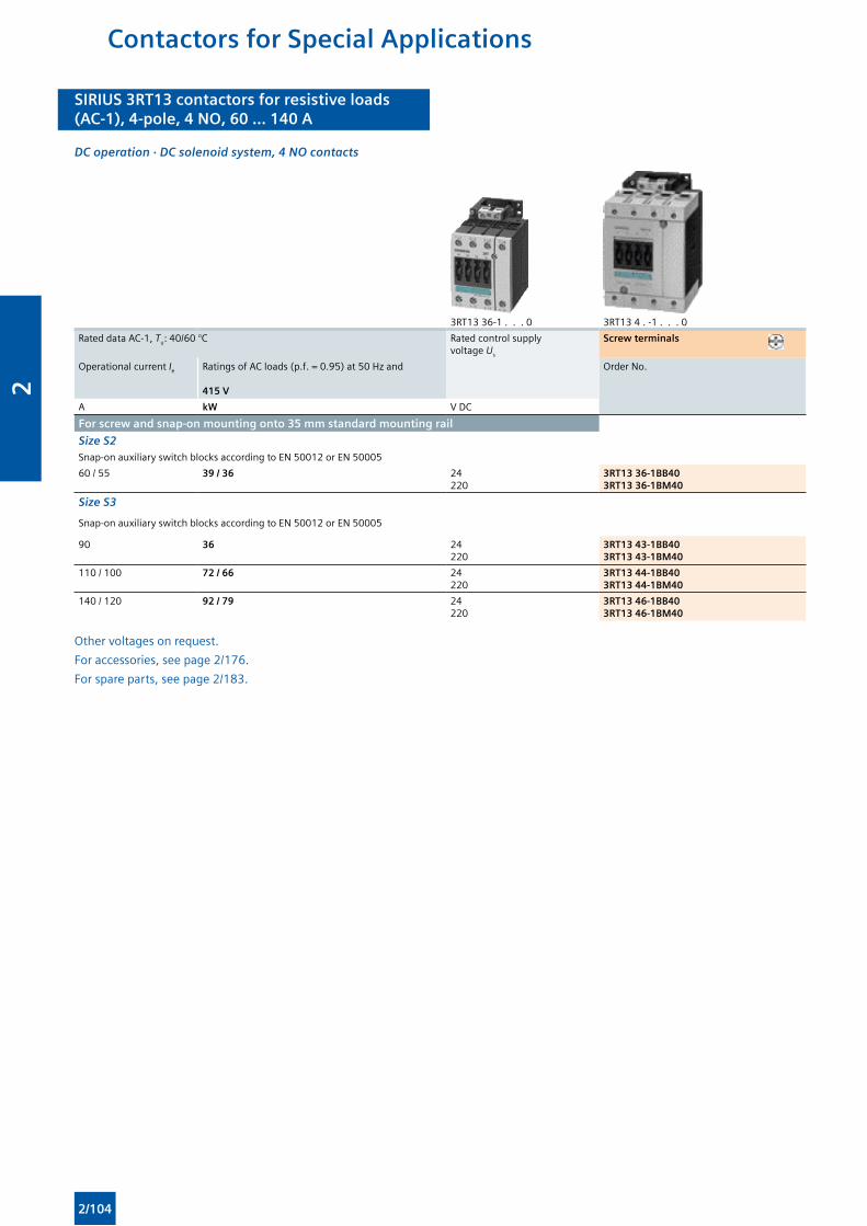
SIRIUS 3RT13 contactors for resistive loads(AC-1), 4-pole, 4 NO, 60 ... 140 A
SIRIUS 3RT13 contactors for resistive loads(AC-1), 4-pole, 4 NO, 60 ... 140 A
DC operation · DC solenoid system, 4 NO contacts
3RT13 36-1 . . . 0 3RT13 4 . -1 . . . 0
Rated data AC-1, Tu: 40/60 °C Rated control supply voltage Us
Screw terminals
Operational current Ie Ratings of AC loads (p.f. = 0.95) at 50 Hz and
415 V
Order No.
A kW V DC
For screw and snap-on mounting onto 35 mm standard mounting rail
Size S2Snap-on auxiliary switch blocks according to EN 50012 or EN 50005
60 / 55 39 / 36 24220
3RT13 36-1BB403RT13 36-1BM40
Size S3
Snap-on auxiliary switch blocks according to EN 50012 or EN 50005
90 36 24220
3RT13 43-1BB403RT13 43-1BM40
110 / 100 72 / 66 24220
3RT13 44-1BB403RT13 44-1BM40
140 / 120 92 / 79 24220
3RT13 46-1BB403RT13 46-1BM40
Other voltages on request.
For accessories, see page 2/176.
For spare parts, see page 2/183.
Contactors for Special Applications
2/104
2
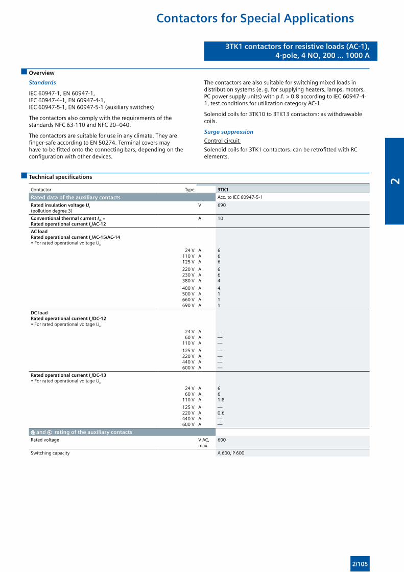
3TK1 contactors for resistive loads (AC-1),4-pole, 4 NO, 200 ... 1000 A
3TK1 contactors for resistive loads (AC-1),4-pole, 4 NO, 200 ... 1000 A
Contactors for Special Applications
Overview
Standards
IEC 60947-1, EN 60947-1, IEC 60947-4-1, EN 60947-4-1, IEC 60947-5-1, EN 60947-5-1 (auxiliary switches)
The contactors also comply with the requirements of the standards NFC 63-110 and NFC 20–040.
The contactors are suitable for use in any climate. They are finger-safe according to EN 50274. Terminal covers may have to be fitted onto the connecting bars, depending on the configuration with other devices.
The contactors are also suitable for switching mixed loads in distribution systems (e. g. for supplying heaters, lamps, motors, PC power supply units) with p.f. > 0.8 according to IEC 60947-4-1, test conditions for utilization category AC-1.
Solenoid coils for 3TK10 to 3TK13 contactors: as withdrawable coils.
Surge suppression
Control circuit
Solenoid coils for 3TK1 contactors: can be retrofitted with RC elements.
Technical specifications
Contactor Type 3TK1
Rated data of the auxiliary contacts Acc. to IEC 60947-5-1
Rated insulation voltage Ui (pollution degree 3)
V 690
Conventional thermal current Ith = Rated operational current Ie/AC-12
A 10
AC load Rated operational current Ie/AC-15/AC-14• For rated operational voltage Ue
24 V110 V125 V
AAA
666
220 V230 V380 V
AAA
664
400 V500 V660 V690 V
AAAA
4111
DC load Rated operational current Ie/DC-12 • For rated operational voltage Ue
24 V60 V
110 V
AAA
———
125 V220 V440 V600 V
AAAA
————
Rated operational current Ie/DC-13 • For rated operational voltage Ue
24 V60 V
110 V
AAA
661.8
125 V220 V440 V600 V
AAAA
—0.6——
and rating of the auxiliary contacts
Rated voltage V AC, max.
600
Switching capacity A 600, P 600
2/105
2

3TK1 contactors for resistive loads (AC-1),4-pole, 4 NO, 200 ... 1000 A
3TK1 contactors for resistive loads (AC-1),4-pole, 4 NO, 200 ... 1000 A
Contactors for Special Applications
Type 3TK10 3TK11 3TK12 3TK13 3TK14 3TK15 3TK17
Dimensions (W x H x D) mm 165 x 156 x 155
165 x 172 x 155
201 x 198 x 172 244 x 273 x 226
General dataPermissible mounting positions
Upright mounting position also permissible
Mechanical endurance Operating cycles Mill. 10 5
Electrical endurance for Ie/AC-1 at 55 °C Operating cycles Mill. 0.8 0.8 0.8 0.4 0.65 0.5 0.4
Rated insulation voltage Ui (pollution degree 3) V 1 000
Ambient temperature
• During operation• During storage
°C°C
-25 ... +55-50 ... +70
Degree of protection acc. to EN 60947-1, Appendix C IP00
Touch protection acc.to EN 50274 Finger-safe with cover
Shock resistance, sine pulse g/ms 10/15
Short-circuit protectionMain circuit Fuse links gG, type NH 3NA, DIAZED 5SB, NEOZED 5SE according to IEC 60947-4-1/ EN 60947-4-1
• Type of coordination “1”• Type of coordination “2”
AA
250250
355315
800630
1 000850
Auxiliary circuit (short-circuit current Ik ≥ 1 kA),fuse links gG, type DIAZED 5SB, NEOZED 5SE
A 10
Control circuitCoil operating range 0.85 ... 1.1 x Us
Power consumption of the solenoid coils (when coil is cold and 1.0 x Us)
• 50 Hz - Closing - P.f. - Closed - P.f.
VA VA
8200.4440.34
1 1000.35520.35
3 5000.261250.4
• 60 Hz - Closing - P.f. - Closed - P.f.
VA VA
9900.35520.35
1 2000.31650.34
4 0000.221400.43
Operating times at 1.0 x Us
• Closing delay• Opening delay
msms
20 ... 407 ... 15
30 ... 6010 ... 20
• Arcing time ms 10 10
Main circuitAC capacityUtilization category AC-1, switching resistive loads
• Rated operational currents Ie At 40° C up to 690 VAt 50 ° C up to 690 V
AA
200180
250230
300270
350310
550470
800650
1000850
• Rated power for AC loads with p.f. = 0.95 (at 40°C)
At 230 V400 V500 V690 V
kWkWkWkW
76132165227
95165206284
114197247341
132230288397
208362452624
303527658908
3786588281135
• Minimum conductor cross-section for load with Ie
At 40° C mm² 95 150 185 240 185 240 300
Utilization categories AC-2 and AC-3
• Rated operational currents Ie Up to 400 V A 120 145 210 210 400 550 700
• Rated power of squirrel-cage or slipring motors at 50 Hz and 60 Hz
At 230 V400 V
kWkW
3055
4575
75110
75110
110200
160280
220370
• Short-time current at 40° C in cold state up to 10 s A 900 1 200 1 600 1 600 5 300 5 300 6 400
Switching frequency1) Switching frequency z in operating cycles/hour
• Contactors without overload relays No-load switching frequency
1/h 3600
AC-1 1/h 300
AC-3 1/h 300
1) Dependence of the switching frequency z ’ on the operational current I ’ and operational voltage U ’ : z ’ = z · (Ie/I ’) · (400 V/U ’)1.5 · 1/h.
2/106
2
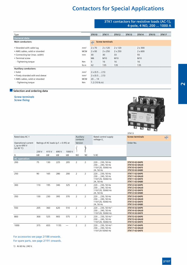
3TK1 contactors for resistive loads (AC-1),4-pole, 4 NO, 200 ... 1000 A
3TK1 contactors for resistive loads (AC-1),4-pole, 4 NO, 200 ... 1000 A
Contactors for Special Applications
Type 3TK10 3TK11 3TK12 3TK13 3TK14 3TK15 3TK17
General dataMain conductors: Screw terminals
• Stranded with cable lug mm2 2 x 70 2 x 120 2 x 120 2 x 300
• AWG cables, solid or stranded MCM 2 x 00 2 x 250 2 x 250 2 x 600
• Connecting bar (max. width) mm 30 30 33 55
• Terminal screw M6 M10 M10 M10
- Tightening torque Nm 5 16 16 16
lb.in 42 135 135 135
Auxiliary conductors:
• Solid mm2 2 x (0.5 ... 2.5)
• Finely stranded with end sleeve mm2 2 x (0.5 ... 2.5)
• AWG cables, solid or stranded MCM 20 ... 14
- Tightening torque Nm 1.2 (10 lb.in)
Selection and ordering data
Screw terminals Screw fixing
3TK13
Rated data AC-1 Auxiliary contacts
Rated control supply voltage Us
Screw terminals
Operational current Ie up to 690 V (at 40 °C)
Ratings of AC loads (p.f. = 0.95) at Version Order No.
230 V 415 V 690 V 1000 V
A kW kW kW kW NO NC V AC
AC operation200 75 130 225 205 2 2 220 ... 230, 50 Hz
230 ... 240, 50 Hz110/120, 50/60 Hz24, 50 Hz
3TK10 42-0AP03TK10 42-0AU03TK10 42-0AF03TK10 42-0AB0
250 90 165 280 200 2 2 220 ... 230, 50 Hz230 ... 240, 50 Hz110/120, 50/60 Hz24, 50 Hz
3TK11 42-0AP03TK11 42-0AU03TK11 42-0AF03TK11 42-0AB0
300 110 195 340 325 2 2 220 ... 230, 50 Hz230 ... 240, 50 Hz110/120, 50/60 Hz24, 50 Hz
3TK12 42-0AP03TK12 42-0AU03TK12 42-0AF03TK12 42-0AB0
350 130 230 395 370 2 2 220 ... 230, 50 Hz230 ... 240, 50 Hz110/120, 50/60 Hz24, 50 Hz
3TK13 42-0AP03TK13 42-0AU03TK13 42-0AF03TK13 42-0AB0
550 205 360 620 510 2 2 220 ... 230, 50 Hz1)
230 ... 240, 50 Hz110/120, 50/60 Hz
3TK14 42-0AP03TK14 42-0AU03TK14 42-0AF0
800 300 525 905 575 2 2 220 ... 230, 50 Hz1)
230 ... 240, 50 Hz110/120, 50/60 Hz
3TK15 42-0AP03TK15 42-0AU03TK15 42-0AF0
1000 375 655 1135 — 2 2 220 ... 230, 50 Hz1)
230 ... 240, 50 Hz110/120 50/60 Hz
3TK17 42-0AP03TK17 42-0AU03TK17 42-0AF0
For accessories see page 2/188 onwards.
For spare parts, see page 2/191 onwards.
1) At 60 Hz: 240 V.
2/107
2
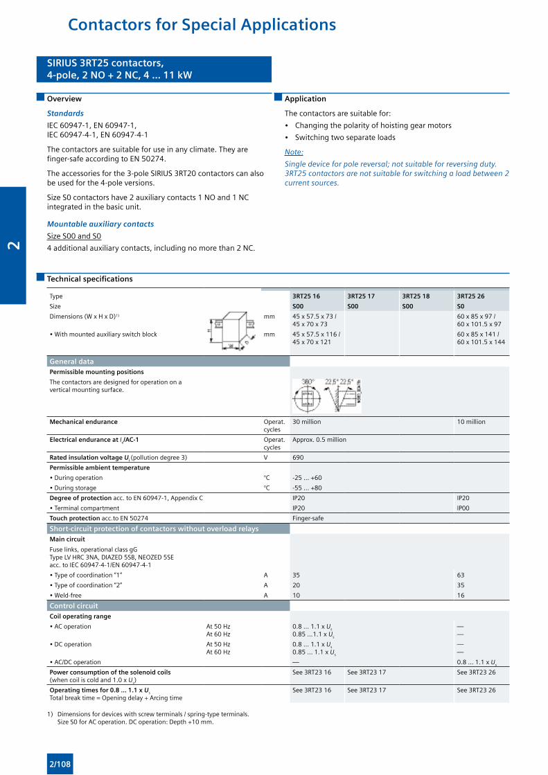
SIRIUS 3RT25 contactors,4-pole, 2 NO + 2 NC, 4 ... 11 kW
SIRIUS 3RT25 contactors,4-pole, 2 NO + 2 NC, 4 ... 11 kW
Contactors for Special Applications
Overview
Standards
IEC 60947-1, EN 60947-1, IEC 60947-4-1, EN 60947-4-1
The contactors are suitable for use in any climate. They are finger-safe according to EN 50274.
The accessories for the 3-pole SIRIUS 3RT20 contactors can also be used for the 4-pole versions.
Size S0 contactors have 2 auxiliary contacts 1 NO and 1 NC integrated in the basic unit.
Mountable auxiliary contacts
Size S00 and S0
4 additional auxiliary contacts, including no more than 2 NC.
Application
The contactors are suitable for:
• Changing the polarity of hoisting gear motors
• Switching two separate loads
Note:
Single device for pole reversal; not suitable for reversing duty. 3RT25 contactors are not suitable for switching a load between 2 current sources.
Technical specifications
Type 3RT25 16 3RT25 17 3RT25 18 3RT25 26
Size S00 S00 S00 S0
Dimensions (W x H x D)1) mm 45 x 57.5 x 73 / 45 x 70 x 73
60 x 85 x 97 / 60 x 101.5 x 97
• With mounted auxiliary switch block mm 45 x 57.5 x 116 / 45 x 70 x 121
60 x 85 x 141 / 60 x 101.5 x 144
General dataPermissible mounting positions
The contactors are designed for operation on a vertical mounting surface.
Mechanical endurance Operat. cycles
30 million 10 million
Electrical endurance at Ie/AC-1 Operat. cycles
Approx. 0.5 million
Rated insulation voltage Ui (pollution degree 3) V 690
Permissible ambient temperature
• During operation °C -25 ... +60
• During storage °C -55 ... +80
Degree of protection acc. to EN 60947-1, Appendix C IP20 IP20
• Terminal compartment IP20 IP00
Touch protection acc.to EN 50274 Finger-safe
Short-circuit protection of contactors without overload relaysMain circuit
Fuse links, operational class gG Type LV HRC 3NA, DIAZED 5SB, NEOZED 5SE acc. to IEC 60947-4-1/EN 60947-4-1
• Type of coordination “1” A 35 63
• Type of coordination “2” A 20 35
• Weld-free A 10 16
Control circuitCoil operating range
• AC operation At 50 HzAt 60 Hz
0.8 ... 1.1 x Us
0.85 ...1.1 x Us
——
• DC operation At 50 HzAt 60 Hz
0.8 ... 1.1 x Us
0.85 ... 1.1 x Us
——
• AC/DC operation — 0.8 ... 1.1 x Us
Power consumption of the solenoid coils (when coil is cold and 1.0 x Us)
See 3RT23 16 See 3RT23 17 See 3RT23 26
Operating times for 0.8 ... 1.1 x Us Total break time = Opening delay + Arcing time
See 3RT23 16 See 3RT23 17 See 3RT23 26
1) Dimensions for devices with screw terminals / spring-type terminals. Size S0 for AC operation. DC operation: Depth +10 mm.
2/108
2
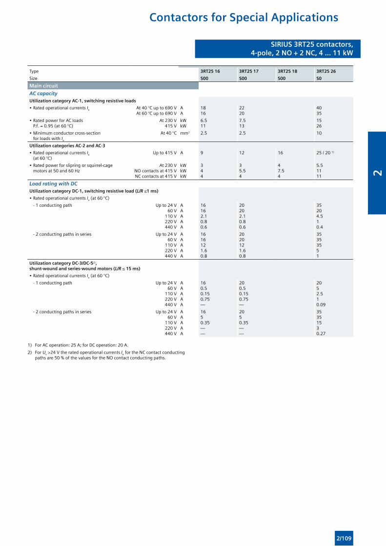
SIRIUS 3RT25 contactors,4-pole, 2 NO + 2 NC, 4 ... 11 kW
SIRIUS 3RT25 contactors,4-pole, 2 NO + 2 NC, 4 ... 11 kW
Contactors for Special Applications
Type 3RT25 16 3RT25 17 3RT25 18 3RT25 26
Size S00 S00 S00 S0
Main circuit
AC capacityUtilization category AC-1, switching resistive loads
• Rated operational currents Ie At 40 °C up to 690 VAt 60 °C up to 690 V
AA
1816
2220
4035
• Rated power for AC loads P.f. = 0.95 (at 60 °C)
At 230 V415 V
kW kW
6.511
7.513
1526
• Minimum conductor cross-section for loads with Ie
At 40 °C mm2 2.5 2.5 10
Utilization categories AC-2 and AC-3
• Rated operational currents Ie (at 60 °C)
Up to 415 V A 9 12 16 25 / 20 1)
• Rated power for slipring or squirrel-cage motors at 50 and 60 Hz
At 230 VNO contacts at 415 VNC contacts at 415 V
kWkWkW
344
3 5.54
47.54
5.51111
Load rating with DCUtilization category DC-1, switching resistive load (L/R ≤1 ms)
• Rated operational currents Ie (at 60 °C)
- 1 conducting path Up to 24 V60 V
110 V220 V440 V
AAAAA
16162.10.80.6
20202.10.80.6
35204.510.4
- 2 conducting paths in series Up to 24 V60 V
110 V220 V440 V
AAAAA
1616121.60.8
2020121.60.8
35353551
Utilization category DC-3/DC-52), shunt-wound and series-wound motors (L/R ≤ 15 ms)
• Rated operational currents Ie (at 60 °C)
- 1 conducting path Up to 24 V60 V
110 V220 V440 V
AAAAA
160.50.150.75—
200.50.150.75—
2052.510.09
- 2 conducting paths in series Up to 24 V60 V
110 V220 V440 V
AAAAA
1650.35——
2050.35——
35351530.27
1) For AC operation: 25 A; for DC operation: 20 A.
2) For Us >24 V the rated operational currents Ie for the NC contact conducting paths are 50 % of the values for the NO contact conducting paths.
2/109
2
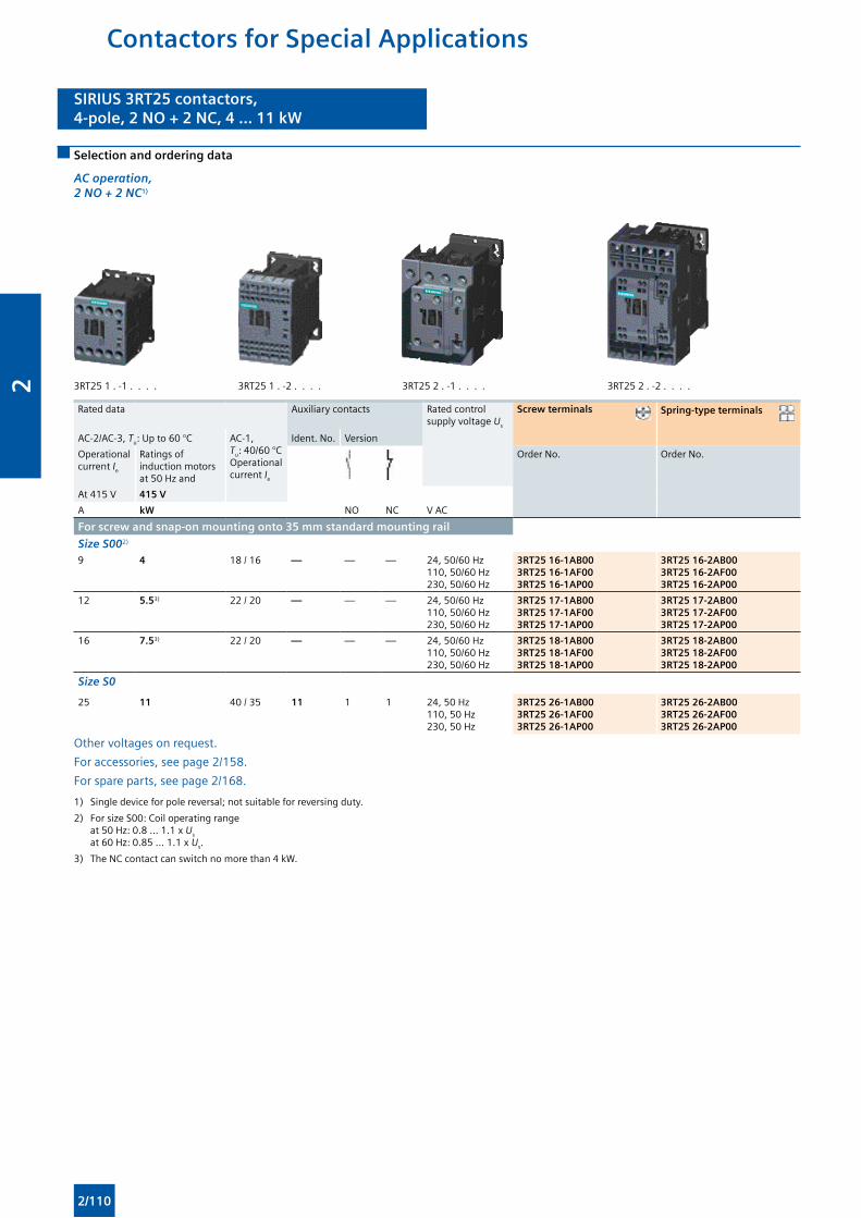
SIRIUS 3RT25 contactors,4-pole, 2 NO + 2 NC, 4 ... 11 kW
SIRIUS 3RT25 contactors,4-pole, 2 NO + 2 NC, 4 ... 11 kW
Contactors for Special Applications
Selection and ordering data
AC operation, 2 NO + 2 NC1)
3RT25 1 . -1 . . . . 3RT25 1 . -2 . . . . 3RT25 2 . -1 . . . . 3RT25 2 . -2 . . . .
Rated data Auxiliary contacts Rated control supply voltage Us
Screw terminals Spring-type terminals
AC-2/AC-3, Tu: Up to 60 °C AC-1, Tu: 40/60 °COperational current Ie
Ident. No. Version
Operational current Ie
Ratings of induction motors at 50 Hz and
Order No. Order No.
At 415 V 415 V
A kW NO NC V AC
For screw and snap-on mounting onto 35 mm standard mounting rail
Size S002) 9 4 18 / 16 — — — 24, 50/60 Hz
110, 50/60 Hz230, 50/60 Hz
3RT25 16-1AB003RT25 16-1AF003RT25 16-1AP00
3RT25 16-2AB003RT25 16-2AF003RT25 16-2AP00
12 5.53) 22 / 20 — — — 24, 50/60 Hz110, 50/60 Hz230, 50/60 Hz
3RT25 17-1AB003RT25 17-1AF003RT25 17-1AP00
3RT25 17-2AB003RT25 17-2AF003RT25 17-2AP00
16 7.53) 22 / 20 — — — 24, 50/60 Hz110, 50/60 Hz230, 50/60 Hz
3RT25 18-1AB003RT25 18-1AF003RT25 18-1AP00
3RT25 18-2AB003RT25 18-2AF003RT25 18-2AP00
Size S0
25 11 40 / 35 11 1 1 24, 50 Hz110, 50 Hz230, 50 Hz
3RT25 26-1AB003RT25 26-1AF003RT25 26-1AP00
3RT25 26-2AB003RT25 26-2AF003RT25 26-2AP00
Other voltages on request.
For accessories, see page 2/158.
For spare parts, see page 2/168.
1) Single device for pole reversal; not suitable for reversing duty.
2) For size S00: Coil operating range at 50 Hz: 0.8 ... 1.1 x Us
at 60 Hz: 0.85 ... 1.1 x Us.
3) The NC contact can switch no more than 4 kW.
2/110
2
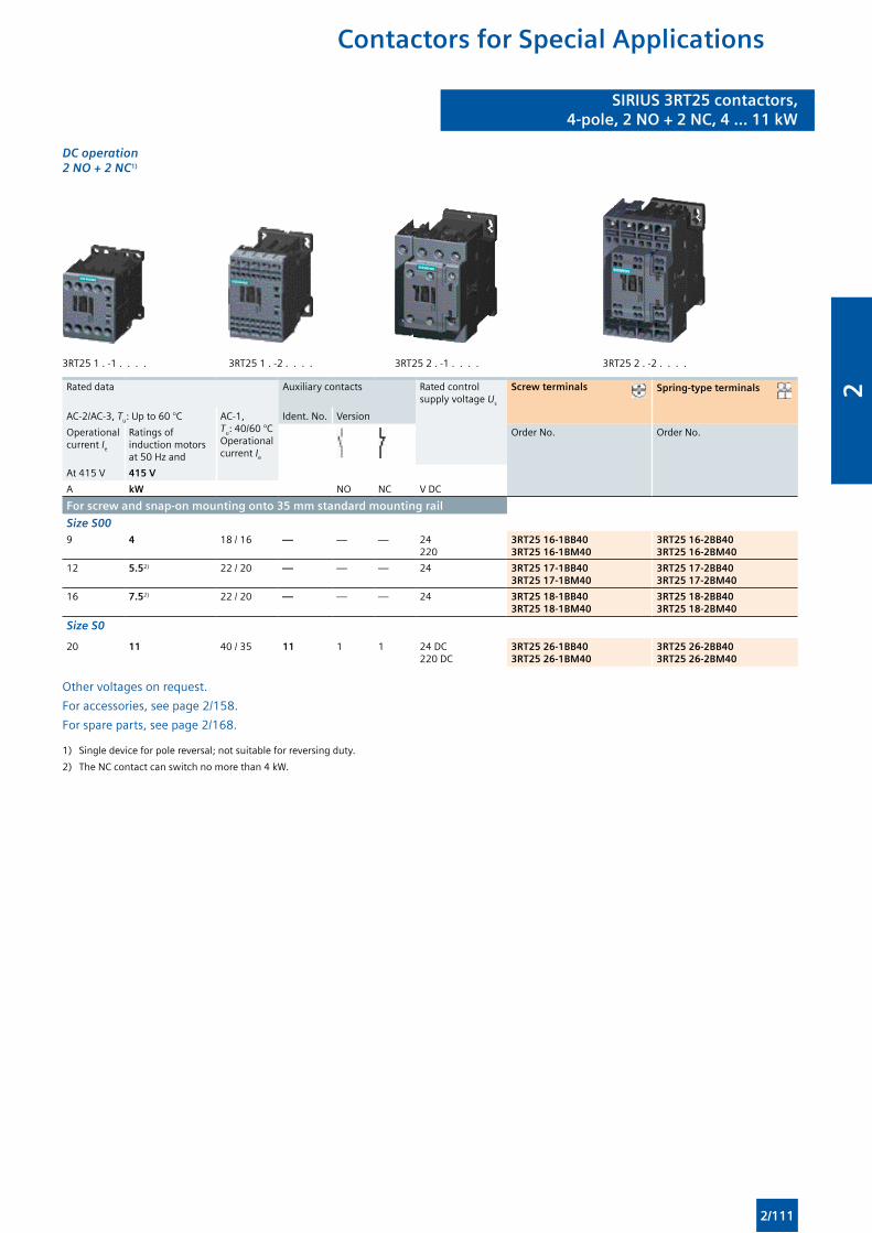
SIRIUS 3RT25 contactors,4-pole, 2 NO + 2 NC, 4 ... 11 kW
SIRIUS 3RT25 contactors,4-pole, 2 NO + 2 NC, 4 ... 11 kW
Contactors for Special Applications
DC operation 2 NO + 2 NC1)
3RT25 1 . -1 . . . . 3RT25 1 . -2 . . . . 3RT25 2 . -1 . . . . 3RT25 2 . -2 . . . .
Rated data Auxiliary contacts Rated control supply voltage Us
Screw terminals Spring-type terminals
AC-2/AC-3, Tu: Up to 60 °C AC-1, Tu: 40/60 °COperational current Ie
Ident. No. Version
Operational current Ie
Ratings of induction motors at 50 Hz and
Order No. Order No.
At 415 V 415 V
A kW NO NC V DC
For screw and snap-on mounting onto 35 mm standard mounting rail
Size S009 4 18 / 16 — — — 24
2203RT25 16-1BB403RT25 16-1BM40
3RT25 16-2BB403RT25 16-2BM40
12 5.52) 22 / 20 — — — 24 3RT25 17-1BB403RT25 17-1BM40
3RT25 17-2BB403RT25 17-2BM40
16 7.52) 22 / 20 — — — 24 3RT25 18-1BB403RT25 18-1BM40
3RT25 18-2BB403RT25 18-2BM40
Size S0
20 11 40 / 35 11 1 1 24 DC220 DC
3RT25 26-1BB403RT25 26-1BM40
3RT25 26-2BB403RT25 26-2BM40
Other voltages on request.
For accessories, see page 2/158.
For spare parts, see page 2/168.
1) Single device for pole reversal; not suitable for reversing duty.
2) The NC contact can switch no more than 4 kW.
2/111
2
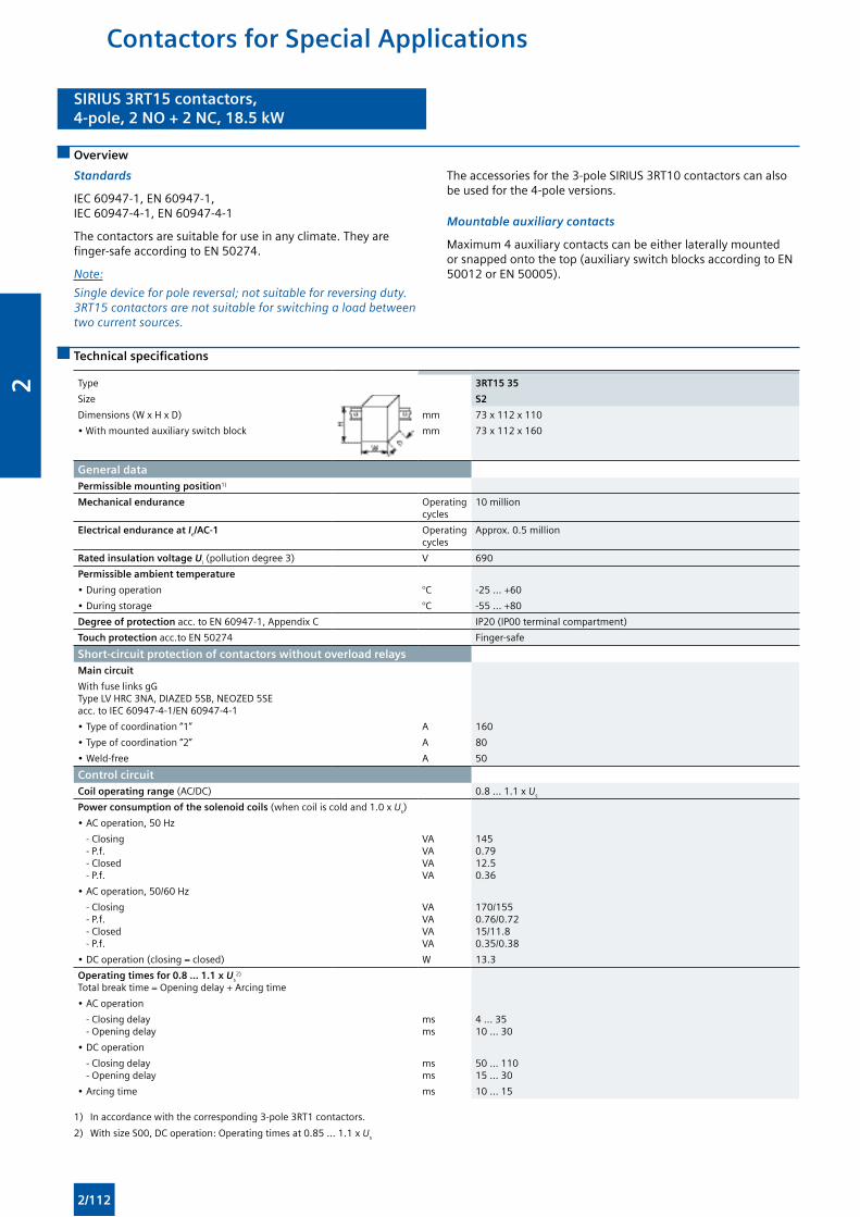
SIRIUS 3RT15 contactors,4-pole, 2 NO + 2 NC, 18.5 kW
SIRIUS 3RT15 contactors,4-pole, 2 NO + 2 NC, 18.5 kW
Contactors for Special Applications
Overview
Standards
IEC 60947-1, EN 60947-1, IEC 60947-4-1, EN 60947-4-1
The contactors are suitable for use in any climate. They are finger-safe according to EN 50274.
Note:
Single device for pole reversal; not suitable for reversing duty. 3RT15 contactors are not suitable for switching a load between two current sources.
The accessories for the 3-pole SIRIUS 3RT10 contactors can also be used for the 4-pole versions.
Mountable auxiliary contacts
Maximum 4 auxiliary contacts can be either laterally mounted or snapped onto the top (auxiliary switch blocks according to EN 50012 or EN 50005).
Technical specifications
Type 3RT15 35
Size S2
Dimensions (W x H x D) mm 73 x 112 x 110
• With mounted auxiliary switch block mm 73 x 112 x 160
General dataPermissible mounting position1)
Mechanical endurance Operating cycles
10 million
Electrical endurance at Ie/AC-1 Operating cycles
Approx. 0.5 million
Rated insulation voltage Ui (pollution degree 3) V 690
Permissible ambient temperature
• During operation °C -25 ... +60
• During storage °C -55 ... +80
Degree of protection acc. to EN 60947-1, Appendix C IP20 (IP00 terminal compartment)
Touch protection acc.to EN 50274 Finger-safe
Short-circuit protection of contactors without overload relaysMain circuit
With fuse links gG Type LV HRC 3NA, DIAZED 5SB, NEOZED 5SEacc. to IEC 60947-4-1/EN 60947-4-1
• Type of coordination “1” A 160
• Type of coordination “2” A 80
• Weld-free A 50
Control circuitCoil operating range (AC/DC) 0.8 ... 1.1 x Us
Power consumption of the solenoid coils (when coil is cold and 1.0 x Us)
• AC operation, 50 Hz
- Closing - P.f. - Closed - P.f.
VAVAVAVA
1450.7912.50.36
• AC operation, 50/60 Hz
- Closing - P.f. - Closed - P.f.
VAVAVAVA
170/1550.76/0.7215/11.80.35/0.38
• DC operation (closing = closed) W 13.3
Operating times for 0.8 ... 1.1 x Us2)
Total break time = Opening delay + Arcing time
• AC operation
- Closing delay - Opening delay
msms
4 ... 3510 ... 30
• DC operation
- Closing delay - Opening delay
msms
50 ... 11015 ... 30
• Arcing time ms 10 ... 15
1) In accordance with the corresponding 3-pole 3RT1 contactors.
2) With size S00, DC operation: Operating times at 0.85 ... 1.1 x Us
2/112
2
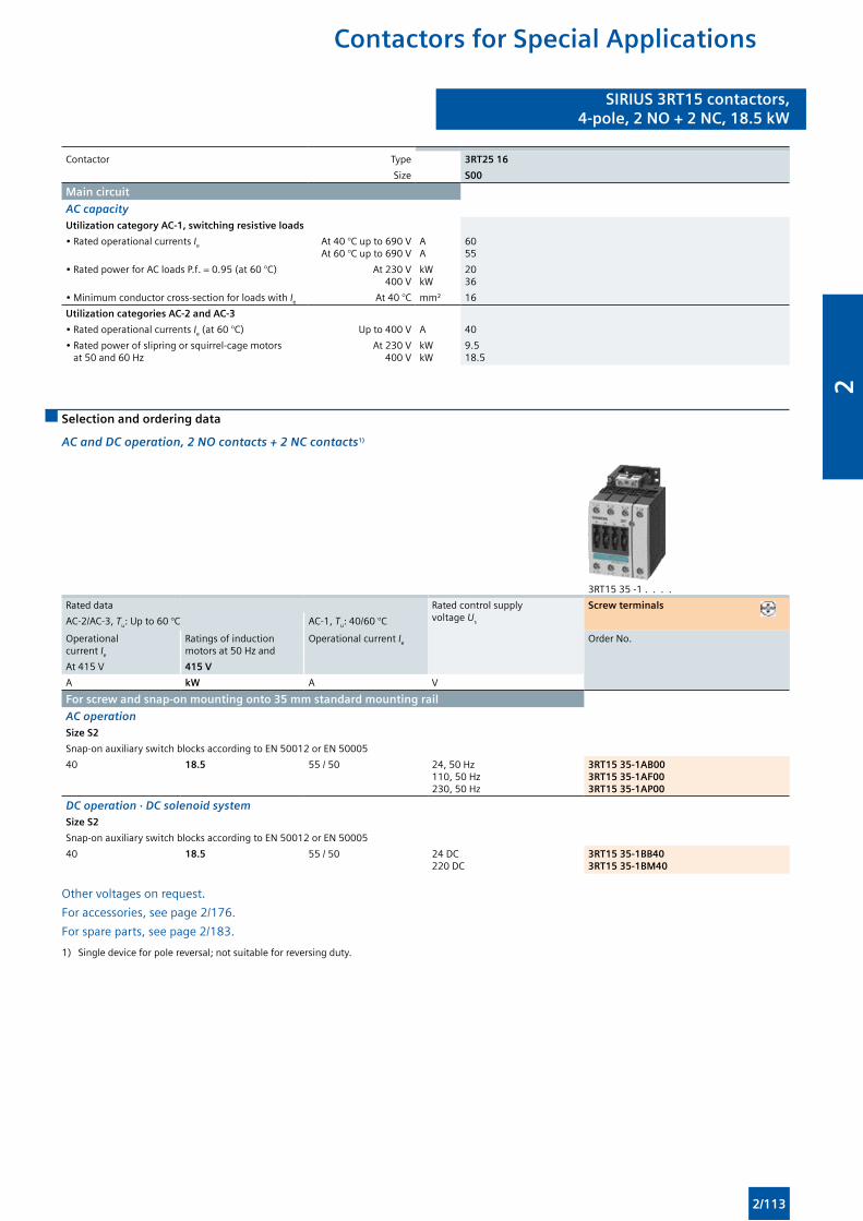
SIRIUS 3RT15 contactors,4-pole, 2 NO + 2 NC, 18.5 kW
SIRIUS 3RT15 contactors,4-pole, 2 NO + 2 NC, 18.5 kW
Contactors for Special Applications
Contactor Type 3RT25 16
Size S00
Main circuit
AC capacityUtilization category AC-1, switching resistive loads
• Rated operational currents Ie At 40 °C up to 690 VAt 60 °C up to 690 V
AA
6055
• Rated power for AC loads P.f. = 0.95 (at 60 °C) At 230 V400 V
kWkW
2036
• Minimum conductor cross-section for loads with Ie At 40 °C mm² 16
Utilization categories AC-2 and AC-3
• Rated operational currents Ie (at 60 °C) Up to 400 V A 40
• Rated power of slipring or squirrel-cage motors at 50 and 60 Hz
At 230 V400 V
kWkW
9.5 18.5
Selection and ordering data
AC and DC operation, 2 NO contacts + 2 NC contacts1)
3RT15 35 -1 . . . .
Rated data Rated control supply voltage Us
Screw terminals
AC-2/AC-3, Tu: Up to 60 °C AC-1, Tu: 40/60 °C
Operational current Ie
Ratings of induction motors at 50 Hz and
Operational current Ie Order No.
At 415 V 415 V
A kW A V
For screw and snap-on mounting onto 35 mm standard mounting rail
AC operationSize S2
Snap-on auxiliary switch blocks according to EN 50012 or EN 50005
40 18.5 55 / 50 24, 50 Hz110, 50 Hz230, 50 Hz
3RT15 35-1AB003RT15 35-1AF003RT15 35-1AP00
DC operation · DC solenoid systemSize S2
Snap-on auxiliary switch blocks according to EN 50012 or EN 50005
40 18.5 55 / 50 24 DC220 DC
3RT15 35-1BB403RT15 35-1BM40
Other voltages on request.
For accessories, see page 2/176.
For spare parts, see page 2/183.
1) Single device for pole reversal; not suitable for reversing duty.
2/113
2
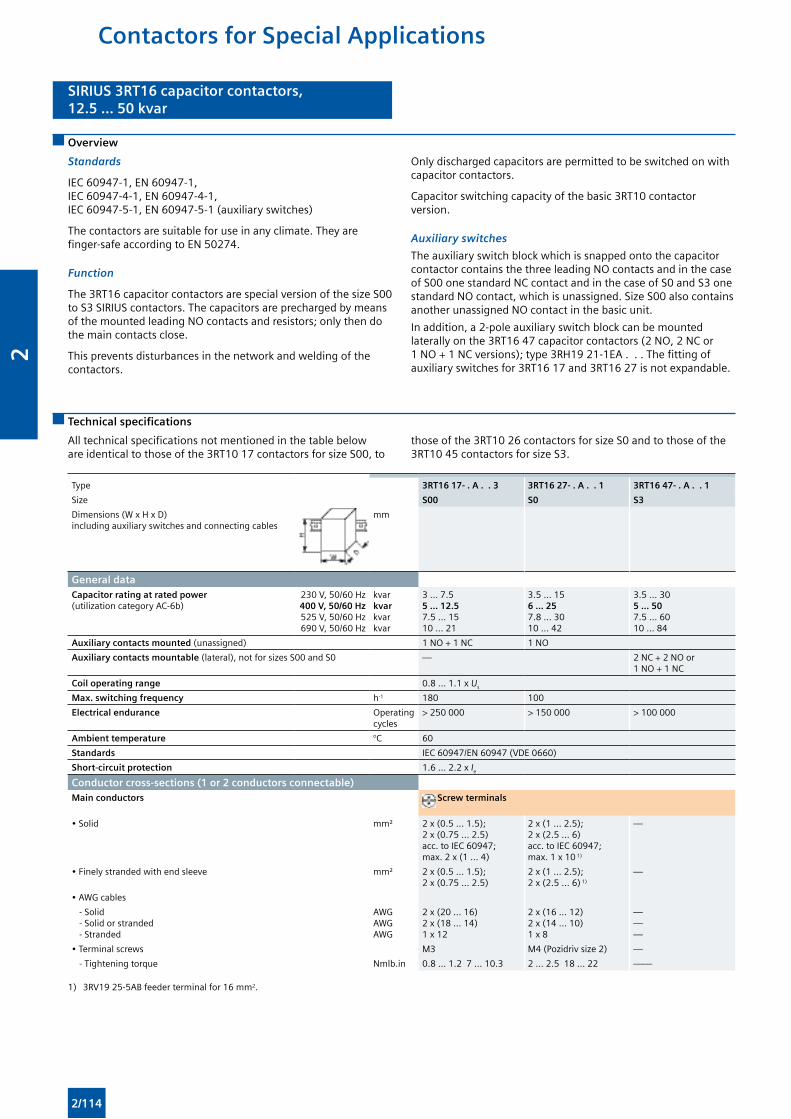
SIRIUS 3RT16 capacitor contactors,12.5 ... 50 kvar
SIRIUS 3RT16 capacitor contactors,12.5 ... 50 kvar
Contactors for Special Applications
Overview
Standards
IEC 60947-1, EN 60947-1, IEC 60947-4-1, EN 60947-4-1, IEC 60947-5-1, EN 60947-5-1 (auxiliary switches)
The contactors are suitable for use in any climate. They are finger-safe according to EN 50274.
Function
The 3RT16 capacitor contactors are special version of the size S00 to S3 SIRIUS contactors. The capacitors are precharged by means of the mounted leading NO contacts and resistors; only then do the main contacts close.
This prevents disturbances in the network and welding of the contactors.
Only discharged capacitors are permitted to be switched on with capacitor contactors.
Capacitor switching capacity of the basic 3RT10 contactor version.
Auxiliary switches
The auxiliary switch block which is snapped onto the capacitor contactor contains the three leading NO contacts and in the case of S00 one standard NC contact and in the case of S0 and S3 one standard NO contact, which is unassigned. Size S00 also contains another unassigned NO contact in the basic unit.
In addition, a 2-pole auxiliary switch block can be mounted laterally on the 3RT16 47 capacitor contactors (2 NO, 2 NC or 1 NO + 1 NC versions); type 3RH19 21-1EA . . . The fitting of auxiliary switches for 3RT16 17 and 3RT16 27 is not expandable.
Technical specifications
All technical specifications not mentioned in the table below are identical to those of the 3RT10 17 contactors for size S00, to
those of the 3RT10 26 contactors for size S0 and to those of the 3RT10 45 contactors for size S3.
Type 3RT16 17- . A . . 3 3RT16 27- . A . . 1 3RT16 47- . A . . 1
Size S00 S0 S3
Dimensions (W x H x D)including auxiliary switches and connecting cables
mm
General dataCapacitor rating at rated power (utilization category AC-6b)
230 V, 50/60 Hz 400 V, 50/60 Hz 525 V, 50/60 Hz690 V, 50/60 Hz
kvarkvarkvarkvar
3 … 7.55 … 12.5 7.5 … 1510 … 21
3.5 … 156 … 25 7.8 … 3010 … 42
3.5 … 305 … 50 7.5 … 6010 … 84
Auxiliary contacts mounted (unassigned) 1 NO + 1 NC 1 NO
Auxiliary contacts mountable (lateral), not for sizes S00 and S0 — 2 NC + 2 NO or 1 NO + 1 NC
Coil operating range 0.8 … 1.1 x Us
Max. switching frequency h-1 180 100
Electrical endurance Operating cycles
> 250 000 > 150 000 > 100 000
Ambient temperature °C 60
Standards IEC 60947/EN 60947 (VDE 0660)
Short-circuit protection 1.6 ... 2.2 x Ie
Conductor cross-sections (1 or 2 conductors connectable)
Main conductors Screw terminals
• Solid mm² 2 x (0.5 ... 1.5); 2 x (0.75 ... 2.5) acc. to IEC 60947; max. 2 x (1 ... 4)
2 x (1 ... 2.5); 2 x (2.5 ... 6) acc. to IEC 60947; max. 1 x 10 1)
—
• Finely stranded with end sleeve mm² 2 x (0.5 ... 1.5); 2 x (0.75 ... 2.5)
2 x (1 ... 2.5); 2 x (2.5 ... 6) 1)
—
• AWG cables
- Solid - Solid or stranded - Stranded
AWGAWGAWG
2 x (20 ... 16)2 x (18 ... 14)1 x 12
2 x (16 ... 12)2 x (14 ... 10)1 x 8
———
• Terminal screws M3 M4 (Pozidriv size 2) —
- Tightening torque Nmlb.in 0.8 ... 1.2 7 ... 10.3 2 ... 2.5 18 ... 22 ——
1) 3RV19 25-5AB feeder terminal for 16 mm2.
2/114
2
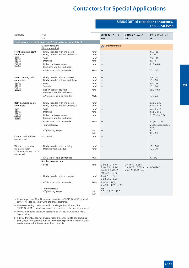
SIRIUS 3RT16 capacitor contactors,12.5 ... 50 kvar
SIRIUS 3RT16 capacitor contactors,12.5 ... 50 kvar
Contactors for Special Applications
Contactor Type 3RT16 17- . A . . 3 3RT16 27- . A . . 1 3RT16 47- . A . . 1
Size S00 S0 S3
Conductor cross-sections (1 or 2 conductors connectable)Main conductors: With box terminal
Screw terminals
Front clamping point connected
• Finely stranded with end sleeve• Finely stranded without end sleeve
mm²mm²
——
2.5 ... 354 ... 50
• Solid• Stranded
mm²mm²
——
2.5 ... 164 ... 70
• Ribbon cable conductors (number x width x thickness)
mm — 6 x 9 x 0.8
• AWG cables, solid or stranded AWG — 10 ... 2/0
Rear clamping point connected
• Finely stranded with end sleeve• Finely stranded without end sleeve
mm²mm²
——
2.5 ... 5010 ... 50
• Solid• Stranded
mm²mm²
——
2.5 ... 1610 ... 70
• Ribbon cable conductors (number x width x thickness)
mm — 6 x 9 x 0.8
• AWG cables, solid or stranded AWG — 10 ... 2/0
Both clamping points connected
• Finely stranded with end sleeve• Finely stranded without end sleeve
mm²mm²
——
max. 2 x 35max. 2 x 35
• Solid• Stranded
mm²mm²
——
max. 2 x 16max. 2 x 50
• Ribbon cable conductors (number x width x thickness)
mm 2 x (6 x 9 x 0.8)
• AWG cables, solid or stranded AWG — 2 x (10 ... 1/0)
• Terminal screw
- Tightening torque Nmlb.in
—
—
M6 (hexagon socket, A/F 4)4 ... 6 36 ... 53
Connection for drilled copper bars1)
Max. width mm — 10
Without box terminal with cable lugs2) (1 or 2 conductors can be connected)
• Finely stranded with cable lug• Stranded with cable lug
mm²mm²
——
10 ... 503)
10 ... 703)
• AWG cables, solid or stranded AWG — 7 ... 1/0
Auxiliary conductors:
• Solid mm² 2 x (0.5 ... 1.5)4); 2 x (0.75 ... 2.5)4) acc. to IEC 60947; max. 2 x (1 ... 4)
2 x (0.5 ... 1.5)4); 2 x (0.75 ... 2.5)4) acc. to IEC 60947; max. 2 x (0.75 ... 4)
• Finely stranded with end sleeve mm² 2 x (0.5 ... 1.5)4); 2 x (0.75 ... 2.5)4)
• AWG cables, solid or stranded AWG 2 x (20 ... 16)4); 2 x (18 ... 14)4); 1 x 12
• Terminal screw - Tightening torque
Nmlb.in
M30.8 ... 1.2 7 ... 10.3
1) If bars larger than 12 × 10 mm are connected, a 3RT19 46-4EA1 terminal cover is needed to comply with the phase clearance.
2) When connecting conductors which are larger than 25 mm2, the 3RT19 46-4EA1 terminal cover must be used to keep the phase clearance.
3) Only with crimped cable lugs according to DIN 46234. Cable lug max. 20 mm wide.
4) If two different conductor cross-sections are connected to one clamping point, both cross-sections must lie in the range specified. If identical cross-sections are used, this restriction does not apply.
2/115
2
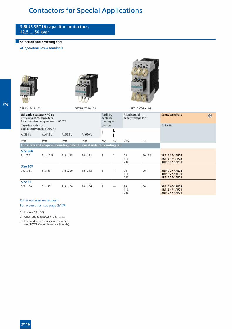
SIRIUS 3RT16 capacitor contactors,12.5 ... 50 kvar
SIRIUS 3RT16 capacitor contactors,12.5 ... 50 kvar
Contactors for Special Applications
Selection and ordering data
AC operation Screw terminals
3RT16 17-1A . 03 3RT16 27-1A . 01 3RT16 47-1A . 01
Utilization category AC-6b Switching of AC capacitors for an ambient temperature of 60 °C1)
Auxiliary contacts, unassigned
Rated control supply voltage Us
2)
Screw terminals
Capacitor rating at operational voltage 50/60 Hz
Version Order No.
At 230 V At 415 V At 525 V At 690 V
kvar kvar kvar kvar NO NC V AC Hz
For screw and snap-on mounting onto 35 mm standard mounting rail
Size S003 … 7.5 5 … 12.5 7.5 … 15 10 … 21 1 1 24
110230
50 / 60 3RT16 17-1AB033RT16 17-1AF033RT16 17-1AP03
Size S03)
3.5 … 15 6 … 25 7.8 … 30 10 … 42 1 — 24110230
50 3RT16 27-1AB013RT16 27-1AF013RT16 27-1AP01
Size S33.5 … 30 5 … 50 7.5 … 60 10 … 84 1 — 24
110230
50 3RT16 47-1AB013RT16 47-1AF013RT16 47-1AP01
Other voltages on request.
For accessories, see page 2/176.
1) For size S3: 55 °C.
2) Operating range: 0.85 ... 1.1 x Us.
3) For conductor cross-sections > 6 mm2
use 3RV19 25-5AB terminals (2 units).
2/116
2
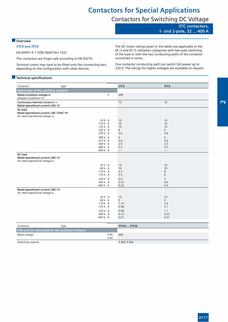
3TC contactors,1- and 2-pole, 32 ... 400 A
3TC contactors,1- and 2-pole, 32 ... 400 A
Overview
3TC4 and 3TC5
EN 60947-4-1 (VDE 0660 Part 102).
The contactors are finger-safe according to EN 50274.
Terminal covers may have to be fitted onto the connecting bars, depending on the configuration with other devices.
The DC motor ratings given in the tables are applicable to the DC-3 and DC-5 utilization categories with two-pole switching of the load or with the two conducting paths of the contactor connected in series.
One contactor conducting path can switch full power up to 220 V. The ratings for higher voltages are available on request.
Technical specifications
Contactor Type 3TC4 3TC5
Rated data of the auxiliary contacts Rated insulation voltage Ui
(degree of pollution 3)V 690
Continuous thermal current Ith = Rated operational current Ie/AC-12
10 10
AC load Rated operational current Ie/AC-15/AC-14for rated operational voltage Ue
24 V110 V125 V220 V230 V
AAAAA
10101065.6
10101065.6
380 V415 V500 V660 V690 V
AAAAA
43.62.52.5—
43.62.52.5—
DC load Rated operational current Ie/DC-12for rated operational voltage Ue
24 V60 V
110 V125 V
AAAA
10103.22.5
101086
220 V440 V600 V
AAA
0.90.330.22
20.60.4
Rated operational current Ie/DC-13 for rated operational voltage Ue
24 V60 V
110 V125 V
AAAA
1051.140.98
1052.42.1
220 V440 V600 V
AAA
0.480.130.07
1.10.320.21
Contactor Type 3TC44 ... 3TC56
CSA and UL rated data for the auxiliary contactsRated voltage V AC,
max.600
Switching capacity A 600, P 600
Contactors for Special ApplicationsContactors for Switching DC Voltage
2/117
2
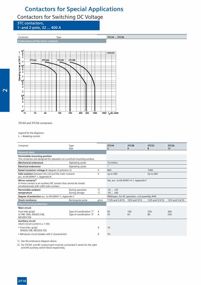
3TC contactors,1- and 2-pole, 32 ... 400 A
3TC contactors,1- and 2-pole, 32 ... 400 A
Contactor Type 3TC44 ... 3TC56
Endurance of the main contacts
3TC44 and 3TC56 contactors
Legend for the diagrams:Ia = Breaking current
Contactor TypeSize
3TC442
3TC484
3TC528
3TC5612
General data
Permissible mounting positionThe contactors are designed for operation on a vertical mounting surface.
Mechanical endurance Operating cycles 10 million
Electrical endurance Operating cycles 1)
Rated insulation voltage Ui (degree of pollution 3) V 800 1000
Safe isolation between the coil and the main contacts acc. to EN 60947-1, Appendix N
V up to 300 Up to 660
Mirror contacts2) A mirror contact is an auxiliary NC contact that cannot be closed simultaneously with a NO main contact.
Yes, acc. to EN 60947-4-1, Appendix F
Permissible ambient temperature
During operationDuring storage
°C°C
-25 ... +55-50 ... +80
Degree of protection acc. to EN 60947-1, Appendix C IP00/open, for AC operation, coil assembly IP40
Shock resistance Rectangular pulse g/ms 7.5/5 and 3.4/10 10/5 and 5/10 12/5 and 5.5/10 12/5 and 5.6/10
Short-circuit protection
Main circuit
Fuse links gL/gG LV HRC 3NA, DIAZED 5SB, NEOZED 5SE
Type of coordination “1”Type of coordination “2”
AA
5035
16063
25080
400250
Auxiliary circuit (short-circuit current Ik ≥ 1 kA)
• Fuse links, gL/gG DIAZED 5SB, NEOZED 5SE
A 16
• Miniature circuit breaker with C characteristic A 10
1) See the endurance diagram above.
2) For 3TC44, one NC contact each must be connected in series for the right and left auxiliary switch block respectively.
Contactors for Special ApplicationsContactors for Switching DC Voltage
2/118
2
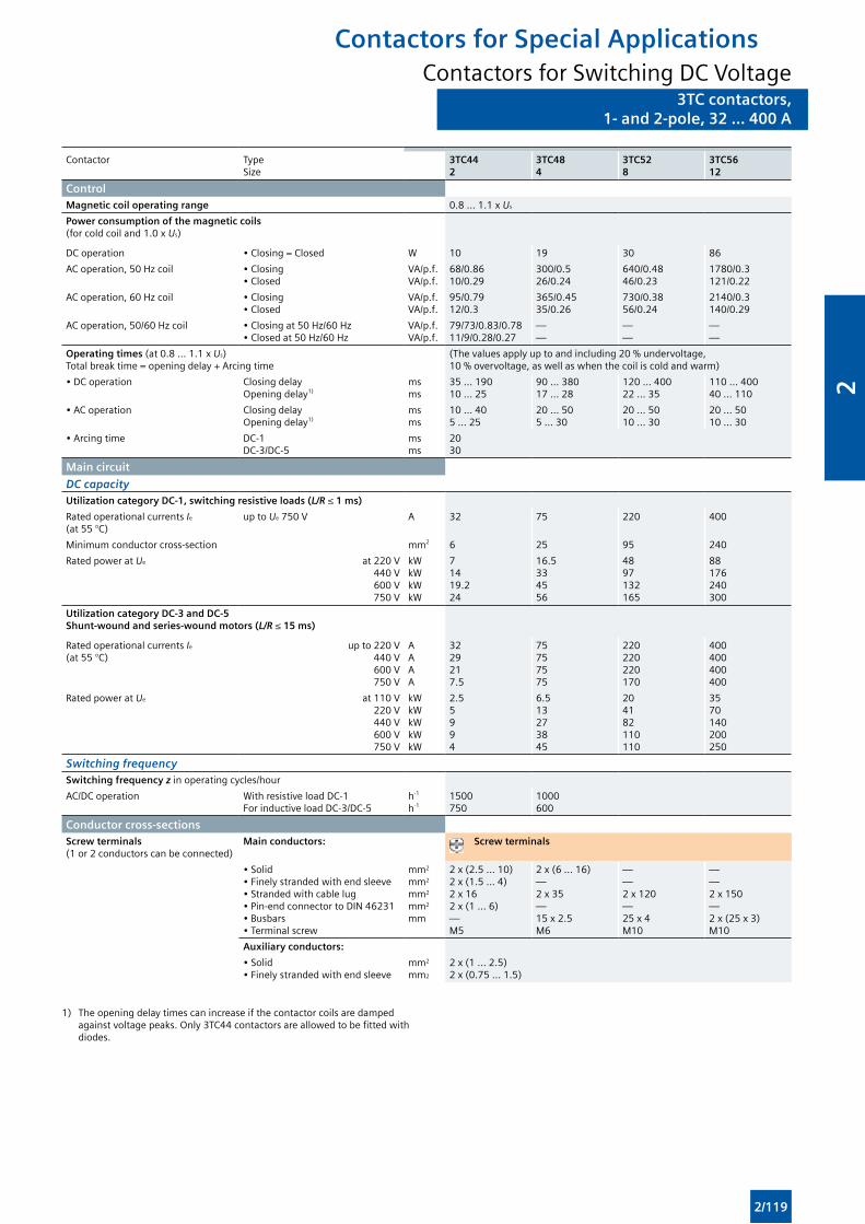
3TC contactors,1- and 2-pole, 32 ... 400 A
3TC contactors,1- and 2-pole, 32 ... 400 A
Contactor TypeSize
3TC442
3TC484
3TC528
3TC5612
ControlMagnetic coil operating range 0.8 ... 1.1 x Us
Power consumption of the magnetic coils (for cold coil and 1.0 x Us)
DC operation • Closing = Closed W 10 19 30 86
AC operation, 50 Hz coil • Closing• Closed
VA/p.f.VA/p.f.
68/0.8610/0.29
300/0.526/0.24
640/0.4846/0.23
1780/0.3121/0.22
AC operation, 60 Hz coil • Closing• Closed
VA/p.f.VA/p.f.
95/0.7912/0.3
365/0.4535/0.26
730/0.3856/0.24
2140/0.3140/0.29
AC operation, 50/60 Hz coil • Closing at 50 Hz/60 Hz• Closed at 50 Hz/60 Hz
VA/p.f.VA/p.f.
79/73/0.83/0.7811/9/0.28/0.27
——
——
——
Operating times (at 0.8 ... 1.1 x Us)Total break time = opening delay + Arcing time
(The values apply up to and including 20 % undervoltage,10 % overvoltage, as well as when the coil is cold and warm)
• DC operation Closing delayOpening delay1)
msms
35 ... 19010 ... 25
90 ... 38017 ... 28
120 ... 40022 ... 35
110 ... 40040 ... 110
• AC operation Closing delayOpening delay1)
msms
10 ... 405 ... 25
20 ... 505 ... 30
20 ... 5010 ... 30
20 ... 5010 ... 30
• Arcing time DC-1DC-3/DC-5
msms
2030
Main circuit
DC capacityUtilization category DC-1, switching resistive loads (L/R ≤ 1 ms)
Rated operational currents Ie
(at 55 °C)up to Ue 750 V A 32 75 220 400
Minimum conductor cross-section mm2 6 25 95 240
Rated power at Ue at 220 V440 V600 V750 V
kWkWkWkW
71419.224
16.5334556
4897132165
88176240300
Utilization category DC-3 and DC-5Shunt-wound and series-wound motors (L/R ≤ 15 ms)
Rated operational currents Ie (at 55 °C)
up to 220 V440 V600 V750 V
AAAA
3229217.5
75757575
220220220170
400400400400
Rated power at Ue at 110 V220 V440 V600 V750 V
kWkWkWkWkW
2.55994
6.513273845
204182110110
3570140200250
Switching frequencySwitching frequency z in operating cycles/hour
AC/DC operation With resistive load DC-1For inductive load DC-3/DC-5
h-1
h-11500750
1000600
Conductor cross-sectionsScrew terminals (1 or 2 conductors can be connected)
Main conductors: Screw terminals
• Solid• Finely stranded with end sleeve• Stranded with cable lug• Pin-end connector to DIN 46231• Busbars• Terminal screw
mm2
mm2
mm2
mm2
mm
2 x (2.5 ... 10) 2 x (1.5 ... 4) 2 x 162 x (1 ... 6) —M5
2 x (6 ... 16)—2 x 35 —15 x 2.5M6
——2 x 120 —25 x 4M10
——2 x 150 —2 x (25 x 3) M10
Auxiliary conductors:
• Solid• Finely stranded with end sleeve
mm2
mm2
2 x (1 ... 2.5)2 x (0.75 ... 1.5)
1) The opening delay times can increase if the contactor coils are damped against voltage peaks. Only 3TC44 contactors are allowed to be fitted with diodes.
Contactors for Special ApplicationsContactors for Switching DC Voltage
2/119
2
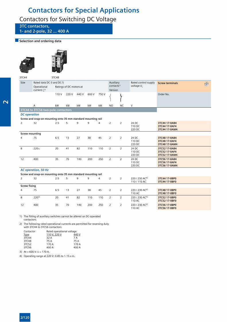
3TC contactors,1- and 2-pole, 32 ... 400 A
3TC contactors,1- and 2-pole, 32 ... 400 A
Selection and ordering data
3TC44 3TC48
Size Rated data DC-3 and DC-5 Auxiliary contacts1)
Version
Rated control supply voltage Us
Screw terminals Operational current Ie
2)
Ratings of DC motors at
110 V 220 V 440 V 600 V 750 V Order No.
A kW kW kW kW kW NO NC V
3TC44 to 3TC56 two-pole contactors
DC operationScrew and snap-on mounting onto 35 mm standard mounting rail
2 32 2.5 5 9 9 4 2 2 24 DC110 DC220 DC
3TC44 17-0AB43TC44 17-0AF43TC44 17-0AM4
Screw mounting
4 75 6.5 13 27 38 45 2 2 24 DC110 DC220 DC
3TC48 17-0AB43TC48 17-0AF43TC48 17-0AM4
8 2203) 20 41 82 110 110 2 2 24 DC110 DC220 DC
3TC52 17-0AB43TC52 17-0AF43TC52 17-0AM4
12 400 35 70 140 200 250 2 2 24 DC110 DC220 DC
3TC56 17-0AB43TC56 17-0AF43TC56 17-0AM4
AC operation, 50 HzScrew and snap-on mounting onto 35 mm standard mounting rail
2 32 2.5 5 9 9 4 2 2 220 / 230 AC4)
110 / 110 AC3TC44 17-0BP03TC44 17-0BF0
Screw fixing
4 75 6.5 13 27 38 45 2 2 220 / 230 AC4)
110 AC3TC48 17-0BP03TC48 17-0BF0
8 2203) 20 41 82 110 110 2 2 220 / 230 AC4)
110 AC3TC52 17-0BP03TC52 17-0BF0
12 400 35 70 140 200 250 2 2 220 / 230 AC4)
110 AC3TC56 17-0BP03TC56 17-0BF0
1) The fitting of auxiliary switches cannot be altered on DC-operated contactors.
2) The following rated operational currents are permitted for reversing duty with 3TC44 to 3TC56 contactors:
Contactor Rated operational voltage Type 110 V, 220 V 440 V 3TC44 32 A 7 A 3TC48 75 A 75 A 3TC52 170 A 170 A 3TC56 400 A 400 A
3) At > 600 V: Ie = 170 A.
4) Operating range at 220 V: 0.85 to 1.15 x Us.
Contactors for Special ApplicationsContactors for Switching DC Voltage
2/120
2
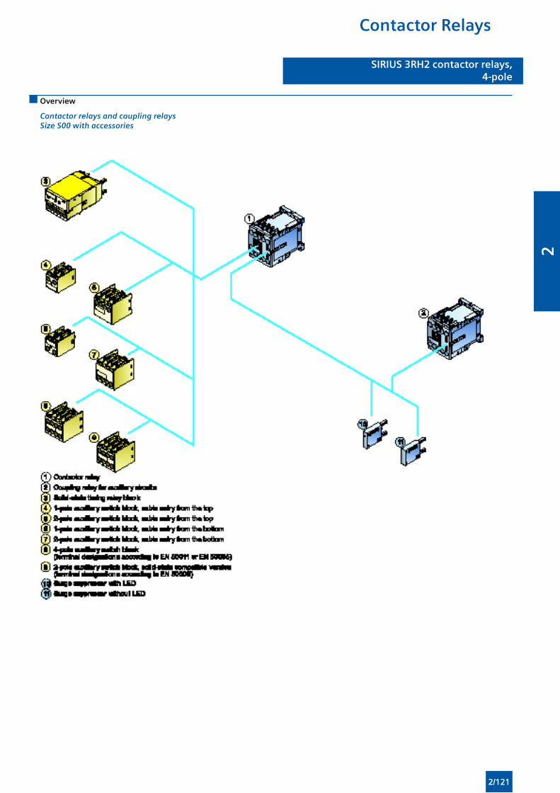
SIRIUS 3RH2 contactor relays,4- and 8-pole
SIRIUS 3RH2 contactor relays,4-pole
Overview
Contactor relays and coupling relays Size S00 with accessories
Contactor Relays
2/121
2
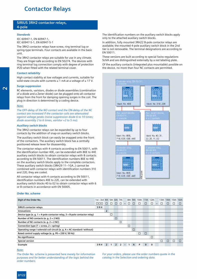
SIRIUS 3RH2 contactor relays,4- and 8-pole
SIRIUS 3RH2 contactor relays,4-pole
Standards
IEC 60947-1, EN 60947-1, IEC 60947-5-1, EN 60947-5-1
The 3RH2 contactor relays have screw, ring terminal lug or spring-type terminals. Four contacts are available in the basic unit.
The 3RH2 contactor relays are suitable for use in any climate. They are finger-safe according to EN 50274. The devices with ring terminal lug connection comply with degree of protection IP20 when fitted with the related terminal cover.
Contact reliability
High contact stability at low voltages and currents, suitable for solid-state circuits with currents ≥ 1 mA at a voltage of ≥ 17 V.
Surge suppression
RC elements, varistors, diodes or diode assemblies (combination of a diode and a Zener diode) can be plugged onto all contactor relays from the front for damping opening surges in the coil. The plug-in direction is determined by a coding device.
Note:
The OFF-delay of the NO contact and the ON-delay of the NC contact are increased if the contactor coils are attenuated against voltage peaks (noise suppression diode 6 to 10 times; diode assembly 2 to 6 times, varistor +2 to 5 ms).
Auxiliary switch blocks
The 3RH2 contactor relays can be expanded by up to four contacts by the addition of snap-on auxiliary switch blocks.
The auxiliary switch block can easily be snapped onto the front of the contactors. The auxiliary switch block has a centrally positioned release lever for disassembly.
The contactor relays with 4 contacts according to EN 50011, with the identification number 40E, can be extended with 80E to 44E auxiliary switch blocks to obtain contactor relays with 8 contacts according to EN 50011. The identification numbers 80E to 44E on the auxiliary switch blocks apply to the complete contactors. These auxiliary switch blocks (3RH29 11–1GA..) cannot be combined with contactor relays with identification numbers 31E and 22E; they are coded.
All contactor relays with 4 contacts according to EN 50011, identification numbers 40E to 22E, can be extended with auxiliary switch blocks 40 to 02 to obtain contactor relays with 6 or 8 contacts in accordance with EN 50005.
The identification numbers on the auxiliary switch blocks apply only to the attached auxiliary switch blocks.
In addition, fully mounted 3RH22 8-pole contactor relays are available; the mounted 4-pole auxiliary switch block in the 2nd tier is not removable. The terminal designations are according to EN 50011.
These versions are built according to special Swiss regulations SUVA and are distinguished externally by a red labeling plate.
Of the auxiliary contacts (integrated plus mountable) possible on the device, no more than four NC contacts are permitted.
Order No. scheme
Digit of the Order No. 1st - 3rd 4th 5th 6th 7th 8th 9th 10th 11th 12th 13th 14th 15th 16th
– –
SIRIUS contactor relays 3 R H
Innovations 2
Device type (e. g. 1 = 4-pole contactor relay, 3 = 8-pole contactor relay)
Number of NO contacts (e. g. 2 = 2 NO)
Number of NC contacts (e. g. 2 = 2 NC)
Connection type (1 = screw, 2 = spring)
Operating range / solenoid coil circuit (e. g. A = AC standard / without)
Rated control supply voltage (e. g. P0 = 230 V, 50 Hz)
No significance
Special version
Example 3 R H 2 1 2 2 – 1 A P 0 0
Note:
The Order No. scheme is presented here merely for information purposes and for better understanding of the logic behind the order numbers.
For your orders, please use the order numbers quote in the catalog in the Selection and ordering data.
Contactor Relays
2/122
2
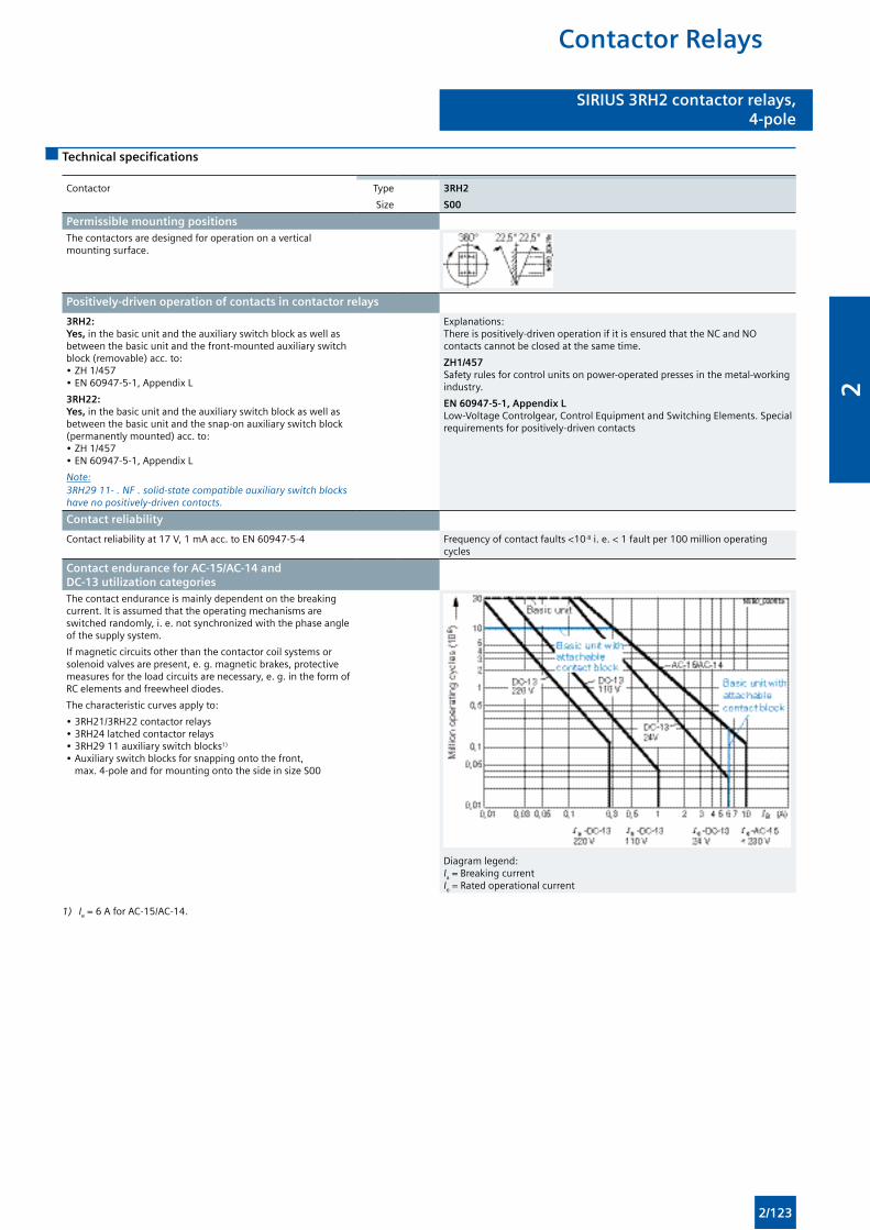
SIRIUS 3RH2 contactor relays,4- and 8-pole
SIRIUS 3RH2 contactor relays,4-pole
Technical specifications
Contactor Type
Size
3RH2
S00
Permissible mounting positionsThe contactors are designed for operation on a vertical mounting surface.
Positively-driven operation of contacts in contactor relays
3RH2: Yes, in the basic unit and the auxiliary switch block as well as between the basic unit and the front-mounted auxiliary switch block (removable) acc. to: • ZH 1/457 • EN 60947-5-1, Appendix L
3RH22: Yes, in the basic unit and the auxiliary switch block as well as between the basic unit and the snap-on auxiliary switch block (permanently mounted) acc. to: • ZH 1/457 • EN 60947-5-1, Appendix L
Note: 3RH29 11- . NF . solid-state compatible auxiliary switch blocks have no positively-driven contacts.
Explanations: There is positively-driven operation if it is ensured that the NC and NO contacts cannot be closed at the same time.
ZH1/457 Safety rules for control units on power-operated presses in the metal-working industry.
EN 60947-5-1, Appendix L Low-Voltage Controlgear, Control Equipment and Switching Elements. Special requirements for positively-driven contacts
Contact reliability
Contact reliability at 17 V, 1 mA acc. to EN 60947-5-4 Frequency of contact faults <10-8 i. e. < 1 fault per 100 million operating cycles
Contact endurance for AC-15/AC-14 and DC-13 utilization categoriesThe contact endurance is mainly dependent on the breaking current. It is assumed that the operating mechanisms are switched randomly, i. e. not synchronized with the phase angle of the supply system.
If magnetic circuits other than the contactor coil systems or solenoid valves are present, e. g. magnetic brakes, protective measures for the load circuits are necessary, e. g. in the form of RC elements and freewheel diodes.
The characteristic curves apply to:
• 3RH21/3RH22 contactor relays • 3RH24 latched contactor relays • 3RH29 11 auxiliary switch blocks1)
• Auxiliary switch blocks for snapping onto the front, max. 4-pole and for mounting onto the side in size S00
Diagram legend: Ia = Breaking current Ie = Rated operational current
1) Ie = 6 A for AC-15/AC-14.
Contactor Relays
2/123
2
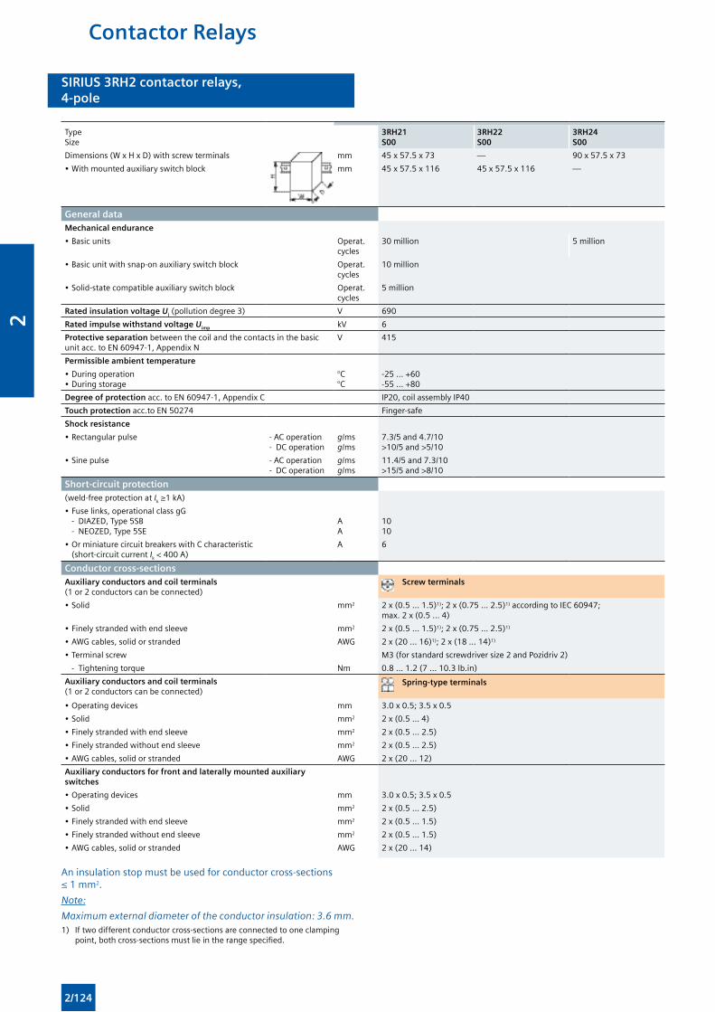
SIRIUS 3RH2 contactor relays,4- and 8-pole
SIRIUS 3RH2 contactor relays,4-pole
TypeSize
3RH21S00
3RH22S00
3RH24S00
Dimensions (W x H x D) with screw terminals mm 45 x 57.5 x 73 — 90 x 57.5 x 73
• With mounted auxiliary switch block mm 45 x 57.5 x 116 45 x 57.5 x 116 —
General dataMechanical endurance
• Basic units Operat. cycles
30 million 5 million
• Basic unit with snap-on auxiliary switch block Operat. cycles
10 million
• Solid-state compatible auxiliary switch block Operat. cycles
5 million
Rated insulation voltage Ui (pollution degree 3) V 690
Rated impulse withstand voltage Uimp kV 6
Protective separation between the coil and the contacts in the basic unit acc. to EN 60947-1, Appendix N
V 415
Permissible ambient temperature
• During operation• During storage
°C°C
-25 ... +60-55 ... +80
Degree of protection acc. to EN 60947-1, Appendix C IP20, coil assembly IP40
Touch protection acc.to EN 50274 Finger-safe
Shock resistance
• Rectangular pulse - AC operation- DC operation
g/msg/ms
7.3/5 and 4.7/10>10/5 and >5/10
• Sine pulse - AC operation- DC operation
g/msg/ms
11.4/5 and 7.3/10>15/5 and >8/10
Short-circuit protection(weld-free protection at Ik ≥1 kA)
• Fuse links, operational class gG - DIAZED, Type 5SB - NEOZED, Type 5SE
AA
1010
• Or miniature circuit breakers with C characteristic (short-circuit current Ik < 400 A)
A 6
Conductor cross-sectionsAuxiliary conductors and coil terminals (1 or 2 conductors can be connected)
Screw terminals
• Solid mm2 2 x (0.5 ... 1.5)1); 2 x (0.75 ... 2.5)1) according to IEC 60947; max. 2 x (0.5 ... 4)
• Finely stranded with end sleeve mm2 2 x (0.5 ... 1.5)1); 2 x (0.75 ... 2.5)1)
• AWG cables, solid or stranded AWG 2 x (20 ... 16)1); 2 x (18 ... 14)1)
• Terminal screw M3 (for standard screwdriver size 2 and Pozidriv 2)
- Tightening torque Nm 0.8 ... 1.2 (7 ... 10.3 lb.in)
Auxiliary conductors and coil terminals (1 or 2 conductors can be connected)
Spring-type terminals
• Operating devices mm 3.0 x 0.5; 3.5 x 0.5
• Solid mm2 2 x (0.5 ... 4)
• Finely stranded with end sleeve mm2 2 x (0.5 ... 2.5)
• Finely stranded without end sleeve mm2 2 x (0.5 ... 2.5)
• AWG cables, solid or stranded AWG 2 x (20 ... 12)
Auxiliary conductors for front and laterally mounted auxiliary switches
• Operating devices mm 3.0 x 0.5; 3.5 x 0.5
• Solid mm2 2 x (0.5 ... 2.5)
• Finely stranded with end sleeve mm2 2 x (0.5 ... 1.5)
• Finely stranded without end sleeve mm2 2 x (0.5 ... 1.5)
• AWG cables, solid or stranded AWG 2 x (20 ... 14)
An insulation stop must be used for conductor cross-sections ≤ 1 mm2.
Note:
Maximum external diameter of the conductor insulation: 3.6 mm.1) If two different conductor cross-sections are connected to one clamping
point, both cross-sections must lie in the range specified.
Contactor Relays
2/124
2
SIRIUS 3RH2 contactor relays,4- and 8-pole
SIRIUS 3RH2 contactor relays,4-pole
Contactor TypeSize
3RH2 .S00
Control circuit Coil operating range
• AC operation At 50 HzAt 60 Hz
0.8 ... 1.1 x Us
0.85 ... 1.1 x Us
• DC operation At 50 °CAt +60 °C
0.8 ... 1.1 x Us
0.85 ... 1.1 x Us
Power consumption of the solenoid coils (when coil is cold and 1.0 x Us)
• AC operation, 50 Hz
- Closing - Closed
VA/p.f.VA/p.f.
37/0.85.7/0.25
• AC operation, 60 Hz
- Closing - Closed
VA/p.f.VA/p.f.
33/0.754.4/0.25
• DC operationClosing = closed W 4.0
Operating times1)
(Total break time = OFF-delay + Arcing time)
Values apply with coil in cold state and at operating temperature for operating range
AC operation
• Closing
- ON-delay of NO contact With 0.8 ... 1.1 x Us
With 1.0 x Us
3RH24 minimum operating time
msmsms
8 ... 339 ... 22≥ 35
- OFF-delay of NC contact With 0.8 ... 1.1 x Us
With 1.0 x Us
msms
6 ... 256.5 ... 19
• Opening
- OFF-delay of NO contact With 0.8 ... 1.1 x Us
With 1.0 x Us
3RH24 minimum operating time
msmsms
4 ... 154.5 ... 15≥ 30
- ON-delay of NC contact With 0.8 ... 1.1 x Us
With 1.0 x Us
msms
5 ... 155 ... 15
DC operation
• Closing
- ON-delay of NO contact With 0.8 ... 1.1 x Us
With 1.0 x Us
3RH24 minimum operating time
msmsms
30 ... 10035 ... 50≥ 100
- OFF-delay of NC contact With 0.8 ... 1.1 x Us
With 1.0 x Us
msms
25 ... 9030 ... 45
• Opening
- OFF-delay of NO contact With 0.8 ... 1.1 x Us
With 1.0 x Us
3RH24 minimum operating time
msmsms
7 ... 137 ... 12≥ 30
- ON-delay of NC contact With 0.8 ... 1.1 x Us
With 1.0 x Us
msms
13 ... 1913 ... 18
• Arcing time ms 10 ... 15
Dependence of the switching frequency z’ on the operational current I’ and operational voltage U’: z’ = z · Ie/I’ · (Ue/U’)1.5 · 1/h
1) The OFF-delay of the NO contact and the ON-delay of the NC contact are increased if the contactor coils are attenuated against voltage peaks (noise suppression diode 6 to 10 times; diode assembly 2 to 6 times, varistor +2 to 5 ms).
Contactor Relays
2/125
2
SIRIUS 3RH2 contactor relays,4- and 8-pole
SIRIUS 3RH2 contactor relays,4-pole
Contactor TypeSize
3RH2.S00
Load sideRated operational currents Ie
AC-12 A 10
AC-15/AC-14For rated operational voltage Us
Up to 230 V400 V500 V690 V
AAAA
101)
321
DC-12For rated operational voltage Us
• 1 conducting path 24 V60 V
110 V220 V440 V600 V
AAAAAA
66310.30.15
• 2 conducting paths in series 24 V60 V
110 V220 V440 V600 V
AAAAAA
1010421.30.65
• 3 conducting paths in series 24 V60 V
110 V220 V440 V600 V
AAAAAA
1010103.62.51.8
DC-13For rated operational voltage Us
• 1 conducting path 24 V60 V
110 V220 V440 V600 V
AAAAAA
6210.30.140.1
• 2 conducting paths in series 24 V60 V
110 V220 V440 V600 V
AAAAAA
103.51.30.90.20.1
• 3 conducting paths in series 24 V60 V
110 V220 V440 V600 V
AAAAAA
104.731.20.50.26
Switching frequency z
• In operating cycles/hduring rated operation for utilization category
AC-12/DC-12AC-15/AC-14
DC-13
h-1
h-1
h-1
100010001000
• No-load switching frequency h-1 10000
Dependence of the switching frequency z’ on the operational current I’ and operational voltage U’: z’ = z · Ie/I’ · (Ue/U’)1.5 · 1/h
Contactor Relays
2/126
2

SIRIUS 3RH2 contactor relays,4- and 8-pole
SIRIUS 3RH2 contactor relays,4-pole
Selection and ordering data
AC operation
Size S00
3RH21 . . -1 . . . . 3RH21 . . -2 . . . .
Rated operational current Ie/AC-15/AC-14 at 230 V
Contacts Rated control supply voltage Us at 50/60 Hz2)
Screw terminals Spring-type terminals
Ident. No. Version
Order No. Order No.
A NO NC V AC
For screw and snap-on mounting onto 35 mm standard mounting rail
Terminal designations according to EN 50011
10 40E 4 — 24110230
3RH21 40-1AB003RH21 40-1AF003RH21 40-1AP00
3RH21 40-2AB003RH21 40-2AF003RH21 40-2AP00
31E 3 1 24110230
3RH21 31-1AB003RH21 31-1AF003RH21 31-1AP00
3RH21 31-2AB003RH21 31-2AF003RH21 31-2AP00
22E 2 2 24110230
3RH21 22-1AB003RH21 22-1AF003RH21 22-1AP00
3RH21 22-2AB003RH21 22-2AF003RH21 22-2AP00
1) Coil operating range at 50 Hz: 0.8 to 1.1 x Us
at 60 Hz: 0.85 to 1.1 x Us.
Contactor Relays
2/127
2
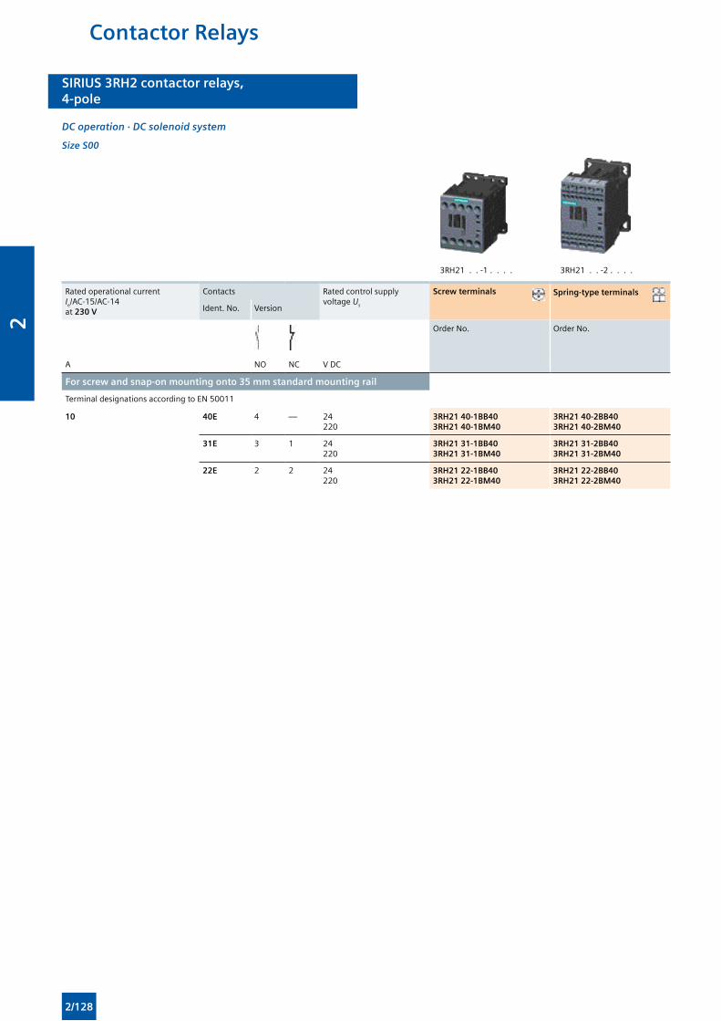
SIRIUS 3RH2 contactor relays,4- and 8-pole
SIRIUS 3RH2 contactor relays,4-pole
DC operation · DC solenoid system
Size S00
3RH21 . . -1 . . . . 3RH21 . . -2 . . . .
Rated operational current Ie/AC-15/AC-14 at 230 V
Contacts Rated control supply voltage Us
Screw terminals Spring-type terminals
Ident. No. Version
Order No. Order No.
A NO NC V DC
For screw and snap-on mounting onto 35 mm standard mounting rail
Terminal designations according to EN 50011
10 40E 4 — 24220
3RH21 40-1BB403RH21 40-1BM40
3RH21 40-2BB403RH21 40-2BM40
31E 3 1 24220
3RH21 31-1BB403RH21 31-1BM40
3RH21 31-2BB403RH21 31-2BM40
22E 2 2 24220
3RH21 22-1BB403RH21 22-1BM40
3RH21 22-2BB403RH21 22-2BM40
Contactor Relays
2/128
2
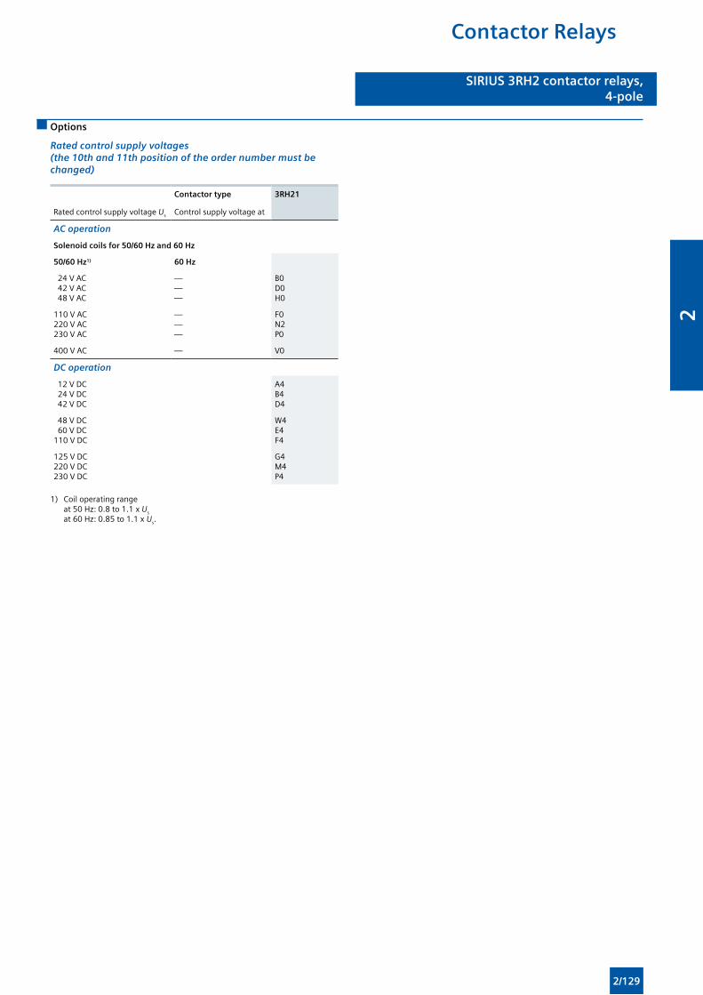
SIRIUS 3RH2 contactor relays,4- and 8-pole
SIRIUS 3RH2 contactor relays,4-pole
Options
Rated control supply voltages (the 10th and 11th position of the order number must be changed)
Contactor type 3RH21
Rated control supply voltage Us Control supply voltage at
AC operation
Solenoid coils for 50/60 Hz and 60 Hz
50/60 Hz1) 60 Hz
24 V AC 42 V AC 48 V AC
———
B0D0H0
110 V AC220 V AC230 V AC
———
F0N2P0
400 V AC — V0
DC operation
12 V DC 24 V DC 42 V DC
A4B4D4
48 V DC 60 V DC110 V DC
W4E4F4
125 V DC220 V DC230 V DC
G4M4P4
1) Coil operating range at 50 Hz: 0.8 to 1.1 x Us
at 60 Hz: 0.85 to 1.1 x Us.
Contactor Relays
2/129
2
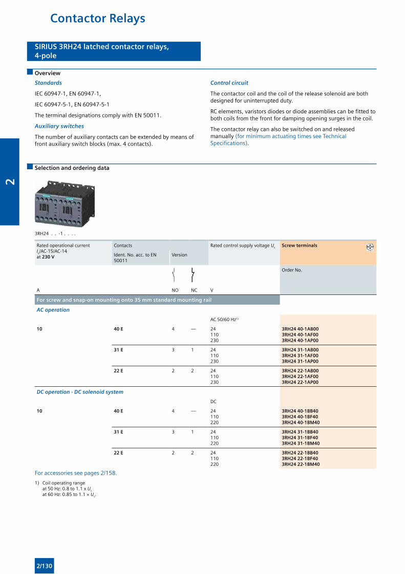
SIRIUS 3RH24 latched contactor relays,4-pole
SIRIUS 3RH24 latched contactor relays,4-pole
Overview
Standards
IEC 60947-1, EN 60947-1,
IEC 60947-5-1, EN 60947-5-1
The terminal designations comply with EN 50011.
Auxiliary switches
The number of auxiliary contacts can be extended by means of front auxiliary switch blocks (max. 4 contacts).
Control circuit
The contactor coil and the coil of the release solenoid are both designed for uninterrupted duty.
RC elements, varistors diodes or diode assemblies can be fitted to both coils from the front for damping opening surges in the coil.
The contactor relay can also be switched on and released manually (for minimum actuating times see Technical Specifications).
Selection and ordering data
3RH24 . . -1 . . . .
Rated operational current Ie/AC-15/AC-14 at 230 V
Contacts Rated control supply voltage Us Screw terminals
Ident. No. acc. to EN 50011
Version
Order No.
A NO NC V
For screw and snap-on mounting onto 35 mm standard mounting rail
AC operation
AC 50/60 Hz1)
10 40 E 4 — 24110230
3RH24 40-1AB003RH24 40-1AF003RH24 40-1AP00
31 E 3 1 24110230
3RH24 31-1AB003RH24 31-1AF003RH24 31-1AP00
22 E 2 2 24110230
3RH24 22-1AB003RH24 22-1AF003RH24 22-1AP00
DC operation · DC solenoid system
DC
10 40 E 4 — 24110220
3RH24 40-1BB403RH24 40-1BF403RH24 40-1BM40
31 E 3 1 24110220
3RH24 31-1BB403RH24 31-1BF403RH24 31-1BM40
22 E 2 2 24110220
3RH24 22-1BB403RH24 22-1BF403RH24 22-1BM40
For accessories see pages 2/158.
1) Coil operating range at 50 Hz: 0.8 to 1.1 x Us
at 60 Hz: 0.85 to 1.1 × Us.
Contactor Relays
2/130
2
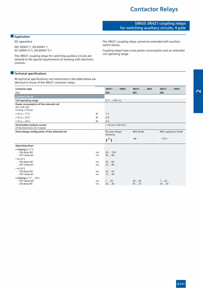
SIRIUS 3RH21 coupling relaysfor switching auxiliary circuits, 4-pole
SIRIUS 3RH21 coupling relaysfor switching auxiliary circuits, 4-pole
Application
DC operation
IIEC 60947-1, EN 60947-1, IEC 60947-5-1, EN 60947-5-1
The 3RH21 coupling relays for switching auxiliary circuits are tailored to the special requirements of working with electronic controls.
The 3RH21 coupling relays cannot be extended with auxiliary switch blocks.
Coupling relays have a low power consumption and an extended coil operating range.
Technical specifications
All technical specifications not mentioned in the table below are identical to those of the 3RH21 contactor relays.
Contactor type 3RH21 . . - . HB40 3RH21 . . - . JB40 3RH21 . . - . KB40
Size S00 S00 S00
Control circuitCoil operating range 0.7 ... 1.85 x Us
Power consumption of the solenoid coil (for cold coil) Closing = Closed
• At Us = 17 V W 1.4
• At Us = 24 V W 2.8
• At Us = 30 V W 4.4
Permissible residual current of the electronics for 0 signal
< 10 mA x (24 V/Us)
Overvoltage configuration of the solenoid coil No overvoltage damping
With diode With suppressor diode
Operating times
• Closing at 17 V - ON-delay NO - OFF-delay NC
msms
40 ... 13030 ... 80
• At 24 V - ON-delay NO - OFF-delay NC
msms
35 ... 6025 ... 40
• At 30 V - ON-delay NO - OFF-delay NC
msms
25 ... 5015 ... 30
• Closing at 17 ... 30 V - OFF-delay NO - ON-delay NC
msms
7 ... 2020 ... 30
38 ... 6555 ... 75
7 ... 2020 ... 30
Contactor Relays
2/131
2
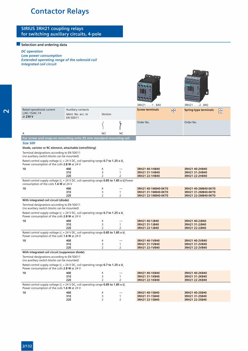
SIRIUS 3RH21 coupling relaysfor switching auxiliary circuits, 4-pole
SIRIUS 3RH21 coupling relaysfor switching auxiliary circuits, 4-pole
Selection and ordering data
DC operation Low power consumption Extended operating range of the solenoid coil Integrated coil circuit
3RH21 . . -1 . B40 3RH21 . . -2 . B40
Rated operational current Ie/AC-15/AC-14 at 230 V
Auxiliary contacts Screw terminals Spring-type terminals
Ident. No. acc. to EN 50011
Version
Order No. Order No.
A NO NC
For screw and snap-on mounting onto 35 mm standard mounting rail
Size S00Diode, varistor or RC element, attachable (retrofitting)
Terminal designations according to EN 50011 (no auxiliary switch blocks can be mounted)
Rated control supply voltage Us = 24 V DC, coil operating range 0.7 to 1.25 x Us
Power consumption of the coils 2.8 W at 24 V
10 40E31E22E
432
—12
3RH21 40-1HB403RH21 31-1HB403RH21 22-1HB40
3RH21 40-2HB403RH21 31-2HB403RH21 22-2HB40
Rated control supply voltage Us = 24 V DC, coil operating range 0.85 to 1.85 x UsPower consumption of the coils 1.6 W at 24 V
10 40E31E22E
432
—12
3RH21 40-1MB40-0KT03RH21 31-1MB40-0KT03RH21 22-1MB40-0KT0
3RH21 40-2MB40-0KT03RH21 31-2MB40-0KT03RH21 22-2MB40-0KT0
With integrated coil circuit (diode)
Terminal designations according to EN 50011 (no auxiliary switch blocks can be mounted)
Rated control supply voltage Us = 24 V DC, coil operating range 0.7 to 1.25 x Us
Power consumption of the coils 2.8 W at 24 V
10 40E31E22E
432
—12
3RH21 40-1JB403RH21 31-1JB403RH21 22-1JB40
3RH21 40-2JB403RH21 31-2JB403RH21 22-2JB40
Rated control supply voltage Us = 24 V DC, coil operating range 0.85 to 1.85 x Us
Power consumption of the coils 1.6 W at 24 V
10 40E31E22E
432
—12
3RH21 40-1VB403RH21 31-1VB403RH21 22-1VB40
3RH21 40-2VB403RH21 31-2VB403RH21 22-2VB40
With integrated coil circuit (suppressor diode)
Terminal designations according to EN 50011 (no auxiliary switch blocks can be mounted)
Rated control supply voltage Us = 24 V DC, coil operating range 0.7 to 1.25 x Us
Power consumption of the coils 2.8 W at 24 V
10 40E31E22E
432
—12
3RH21 40-1KB403RH21 31-1KB403RH21 22-1KB40
3RH21 40-2KB403RH21 31-2KB403RH21 22-2KB40
Rated control supply voltage Us = 24 V DC, coil operating range 0.85 to 1.85 x Us
Power consumption of the coils 1.6 W at 24 V
10 40E31E22E
432
—12
3RH21 40-1SB403RH21 31-1SB403RH21 22-1SB40
3RH21 40-2SB403RH21 31-2SB403RH21 22-2SB40
Contactor Relays
2/132
2

SIRIUS 3RT20 coupling contactors (interface),3-pole, 3 ... 15 kW
SIRIUS 3RT20 coupling contactors (interface),3-pole, 3 ... 15 kW
Application
DC operation
IEC 60947-1, EN 60947-1, IEC 60947-4-1, EN 60947-4-1, IEC 60947-5-1, EN 60947-5-1 (auxiliary switches)
The 3RT20 coupling contactors for switching motors are tailored to the special requirements of working with electronic controls.
The 3RT20 1 coupling contactors cannot be extended with auxiliary switch blocks.
Coupling contactors have a low power consumption and an extended solenoid coil operating range.
Technical specifications
All technical specifications not mentioned in the table below are identical to those of the 3RT20 contactors for switching.
Contactor TypeSize
3RT20 1 . - . HB4 .S00
3RT20 1 . - . JB4 .S00
3RT20 1 . - . KB4 .S00
3RT20 2 . - . KB4 .S0
General dataMechanical endurance Operating
cycles30 million 10 million
Safe isolation between the coil and the main contacts acc. to EN 60947-1, Appendix N
V 415
Control circuitCoil operating range 0.7 ... 1.25 x Us
Power consumption of the solenoid coil (for cold coil) Closing = Closed
At Us 17 V W 1.6 2.3
24 V W 2.8 4.5
30 V W 4.4 7
Permissible residual current of the electronics (with 0 signal)
< 10 mA x (24 V/Us) < 6 mA x (24 V/Us)
Overvoltage configuration of the solenoid coil No overvoltage damping
With diode With suppressor diode
With varistor
Operating times
• Closing
- At 17 V ON-delay NOOFF-delay NC
msms
40 ... 13030 ... 80
70 ... 27060 ... 250
- At 24 V ON-delay NOOFF-delay NC
msms
35 ... 6025 ... 40
65 ... 9055 ... 80
- At 30 V ON-delay NOOFF-delay NC
msms
25 ... 5015 ... 30
52 ... 6543 ... 57
• Closing at 17 ... 30 V OFF-delay NOON-delay NC
msms
7 ... 2020 ... 30
38 ... 6555 ... 75
7 ... 2020 ... 30
19 ... 2125 ... 31
Coupling Contactors
2/133
2
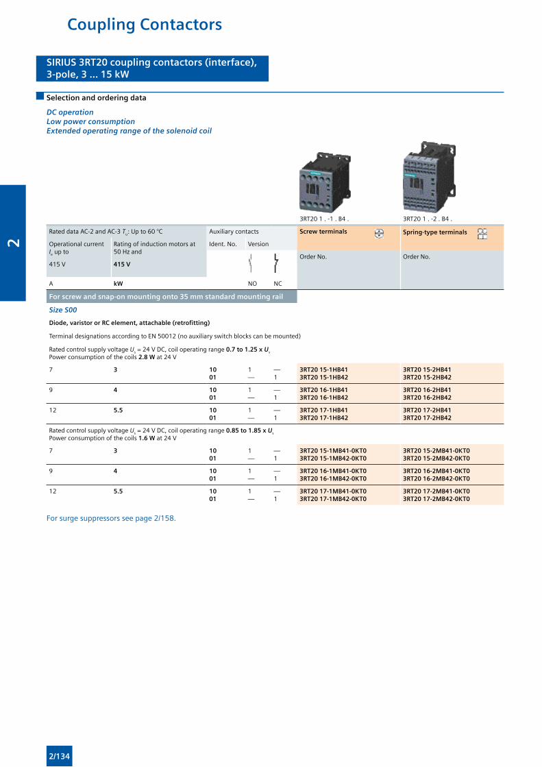
SIRIUS 3RT20 coupling contactors (interface),3-pole, 3 ... 15 kW
SIRIUS 3RT20 coupling contactors (interface),3-pole, 3 ... 15 kW
Selection and ordering data
DC operationLow power consumptionExtended operating range of the solenoid coil
3RT20 1 . -1 . B4 . 3RT20 1 . -2 . B4 .
Rated data AC-2 and AC-3 Tu: Up to 60 °C Auxiliary contacts Screw terminals Spring-type terminals
Operational current Ie up to
Rating of induction motors at 50 Hz and
Ident. No. Version
Order No. Order No.415 V 415 V
A kW NO NC
For screw and snap-on mounting onto 35 mm standard mounting rail
Size S00
Diode, varistor or RC element, attachable (retrofitting)
Terminal designations according to EN 50012 (no auxiliary switch blocks can be mounted)
Rated control supply voltage Us = 24 V DC, coil operating range 0.7 to 1.25 x Us
Power consumption of the coils 2.8 W at 24 V
7 3 1001
1—
—1
3RT20 15-1HB413RT20 15-1HB42
3RT20 15-2HB413RT20 15-2HB42
9 4 1001
1—
—1
3RT20 16-1HB413RT20 16-1HB42
3RT20 16-2HB413RT20 16-2HB42
12 5.5 1001
1—
—1
3RT20 17-1HB413RT20 17-1HB42
3RT20 17-2HB413RT20 17-2HB42
Rated control supply voltage Us = 24 V DC, coil operating range 0.85 to 1.85 x Us
Power consumption of the coils 1.6 W at 24 V
7 3 1001
1—
—1
3RT20 15-1MB41-0KT03RT20 15-1MB42-0KT0
3RT20 15-2MB41-0KT03RT20 15-2MB42-0KT0
9 4 1001
1—
—1
3RT20 16-1MB41-0KT03RT20 16-1MB42-0KT0
3RT20 16-2MB41-0KT03RT20 16-2MB42-0KT0
12 5.5 1001
1—
—1
3RT20 17-1MB41-0KT03RT20 17-1MB42-0KT0
3RT20 17-2MB41-0KT03RT20 17-2MB42-0KT0
For surge suppressors see page 2/158.
Coupling Contactors
2/134
2
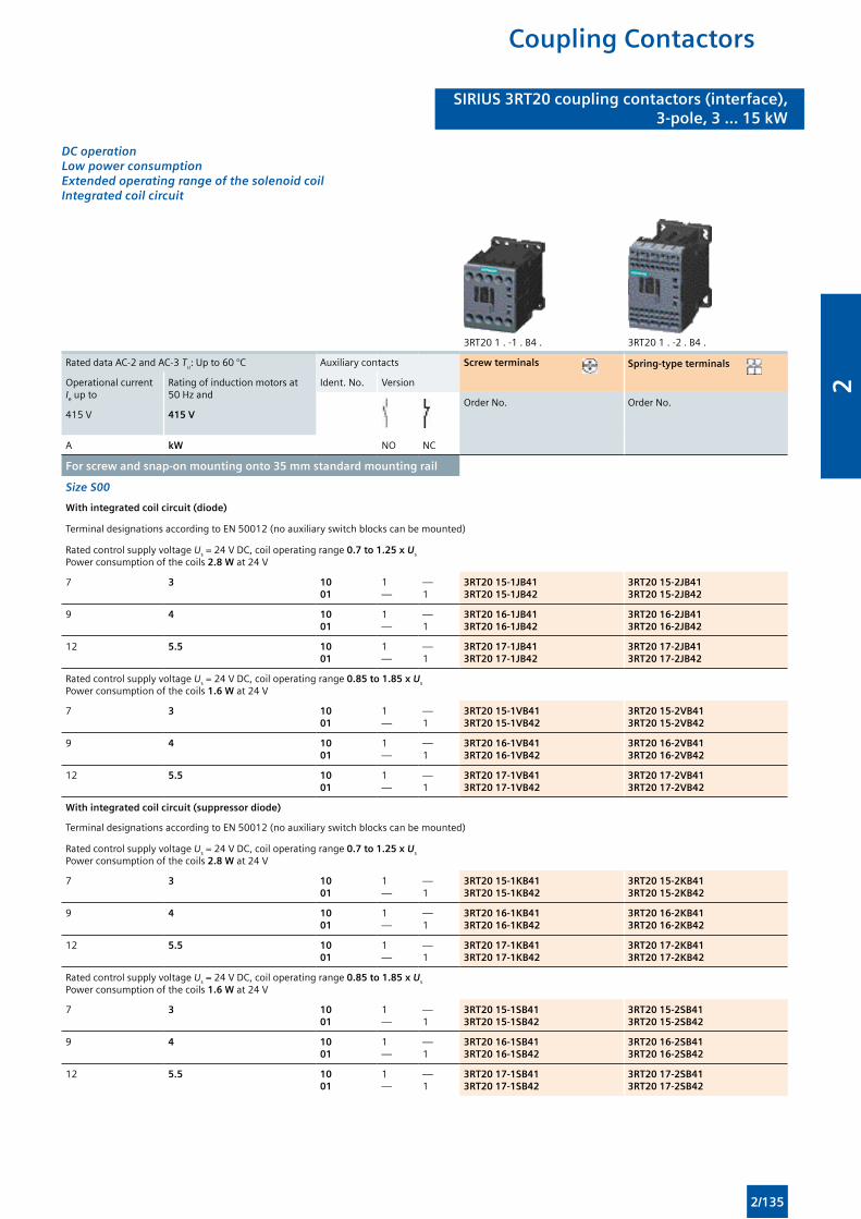
SIRIUS 3RT20 coupling contactors (interface),3-pole, 3 ... 15 kW
SIRIUS 3RT20 coupling contactors (interface),3-pole, 3 ... 15 kW
DC operationLow power consumptionExtended operating range of the solenoid coilIntegrated coil circuit
3RT20 1 . -1 . B4 . 3RT20 1 . -2 . B4 .
Rated data AC-2 and AC-3 Tu: Up to 60 °C Auxiliary contacts Screw terminals Spring-type terminals
Operational current Ie up to
Rating of induction motors at 50 Hz and
Ident. No. Version
Order No. Order No.415 V 415 V
A kW NO NC
For screw and snap-on mounting onto 35 mm standard mounting rail
Size S00
With integrated coil circuit (diode)
Terminal designations according to EN 50012 (no auxiliary switch blocks can be mounted)
Rated control supply voltage Us = 24 V DC, coil operating range 0.7 to 1.25 x Us
Power consumption of the coils 2.8 W at 24 V
7 3 1001
1—
—1
3RT20 15-1JB413RT20 15-1JB42
3RT20 15-2JB413RT20 15-2JB42
9 4 1001
1—
—1
3RT20 16-1JB413RT20 16-1JB42
3RT20 16-2JB413RT20 16-2JB42
12 5.5 1001
1—
—1
3RT20 17-1JB413RT20 17-1JB42
3RT20 17-2JB413RT20 17-2JB42
Rated control supply voltage Us = 24 V DC, coil operating range 0.85 to 1.85 x Us
Power consumption of the coils 1.6 W at 24 V
7 3 1001
1—
—1
3RT20 15-1VB413RT20 15-1VB42
3RT20 15-2VB413RT20 15-2VB42
9 4 1001
1—
—1
3RT20 16-1VB413RT20 16-1VB42
3RT20 16-2VB413RT20 16-2VB42
12 5.5 1001
1—
—1
3RT20 17-1VB413RT20 17-1VB42
3RT20 17-2VB413RT20 17-2VB42
With integrated coil circuit (suppressor diode)
Terminal designations according to EN 50012 (no auxiliary switch blocks can be mounted)
Rated control supply voltage Us = 24 V DC, coil operating range 0.7 to 1.25 x Us
Power consumption of the coils 2.8 W at 24 V
7 3 1001
1—
—1
3RT20 15-1KB413RT20 15-1KB42
3RT20 15-2KB413RT20 15-2KB42
9 4 1001
1—
—1
3RT20 16-1KB413RT20 16-1KB42
3RT20 16-2KB413RT20 16-2KB42
12 5.5 1001
1—
—1
3RT20 17-1KB413RT20 17-1KB42
3RT20 17-2KB413RT20 17-2KB42
Rated control supply voltage Us = 24 V DC, coil operating range 0.85 to 1.85 x Us
Power consumption of the coils 1.6 W at 24 V
7 3 1001
1—
—1
3RT20 15-1SB413RT20 15-1SB42
3RT20 15-2SB413RT20 15-2SB42
9 4 1001
1—
—1
3RT20 16-1SB413RT20 16-1SB42
3RT20 16-2SB413RT20 16-2SB42
12 5.5 1001
1—
—1
3RT20 17-1SB413RT20 17-1SB42
3RT20 17-2SB413RT20 17-2SB42
Coupling Contactors
2/135
2
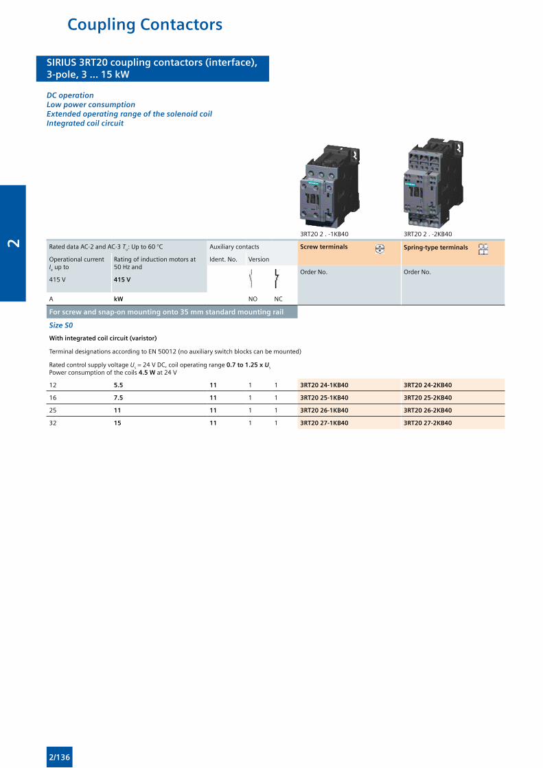
SIRIUS 3RT20 coupling contactors (interface),3-pole, 3 ... 15 kW
SIRIUS 3RT20 coupling contactors (interface),3-pole, 3 ... 15 kW
DC operationLow power consumptionExtended operating range of the solenoid coilIntegrated coil circuit
3RT20 2 . -1KB40 3RT20 2 . -2KB40
Rated data AC-2 and AC-3 Tu: Up to 60 °C Auxiliary contacts Screw terminals Spring-type terminals
Operational current Ie up to
Rating of induction motors at 50 Hz and
Ident. No. Version
Order No. Order No.415 V 415 V
A kW NO NC
For screw and snap-on mounting onto 35 mm standard mounting rail
Size S0
With integrated coil circuit (varistor)
Terminal designations according to EN 50012 (no auxiliary switch blocks can be mounted)
Rated control supply voltage Us = 24 V DC, coil operating range 0.7 to 1.25 x Us
Power consumption of the coils 4.5 W at 24 V
12 5.5 11 1 1 3RT20 24-1KB40 3RT20 24-2KB40
16 7.5 11 1 1 3RT20 25-1KB40 3RT20 25-2KB40
25 11 11 1 1 3RT20 26-1KB40 3RT20 26-2KB40
32 15 11 1 1 3RT20 27-1KB40 3RT20 27-2KB40
Coupling Contactors
2/136
2
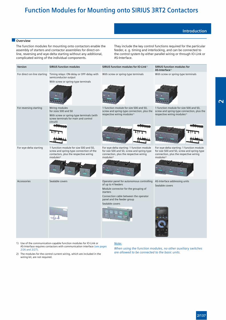
Introduction Introduction
Overview
The function modules for mounting onto contactors enable the assembly of starters and contactor assemblies for direct-on-line, reversing and wye-delta starting without any additional, complicated wiring of the individual components.
They include the key control functions required for the particular feeder, e. g. timing and interlocking, and can be connected to the control system by either parallel wiring or through IO-Link or AS-Interface.
Version SIRIUS function modules SIRIUS function modules for IO-Link1) SIRIUS function modules for AS-Interface1)
For direct-on-line starting Timing relays: ON-delay or OFF-delay with semiconductor output
With screw or spring-type terminals
With screw or spring-type terminals With screw or spring-type terminals
For reversing starting Wiring modules for sizes S00 and S0
With screw or spring-type terminals (with screw terminals for main and control circuit)
1 function module for size S00 and S0, screw and spring-type connection, plus the respective wiring modules1)
1 function module for size S00 and S0, screw and spring-type connection, plus the respective wiring modules1)
For wye-delta starting 1 function module for size S00 and S0, screw and spring-type connection of the contactors, plus the respective wiring modules2)
For wye-delta starting: 1 function module for size S00 and S0, screw and spring-type connection, plus the respective wiring modules2)
For wye-delta starting: 1 function module for size S00 and S0, screw and spring-type connection, plus the respective wiring modules2)
Accessories Sealable covers Operator panel for autonomous controlling of up to 4 feeders
Module connector for the grouping of starters
Connection cable between the operator panel and the feeder group
Sealable covers
AS-Interface addressing units
Sealable covers
1) Use of the communication-capable function modules for IO-Link or AS-Interface requires contactors with communication interface (see pages 2/26 and 2/27).
2) The modules for the control current wiring, which are included in the wiring kit, are not required.
Note:
When using the function modules, no other auxiliary switches are allowed to be connected to the basic units.
Function Modules for Mounting onto SIRIUS 3RT2 Contactors
2/137
2
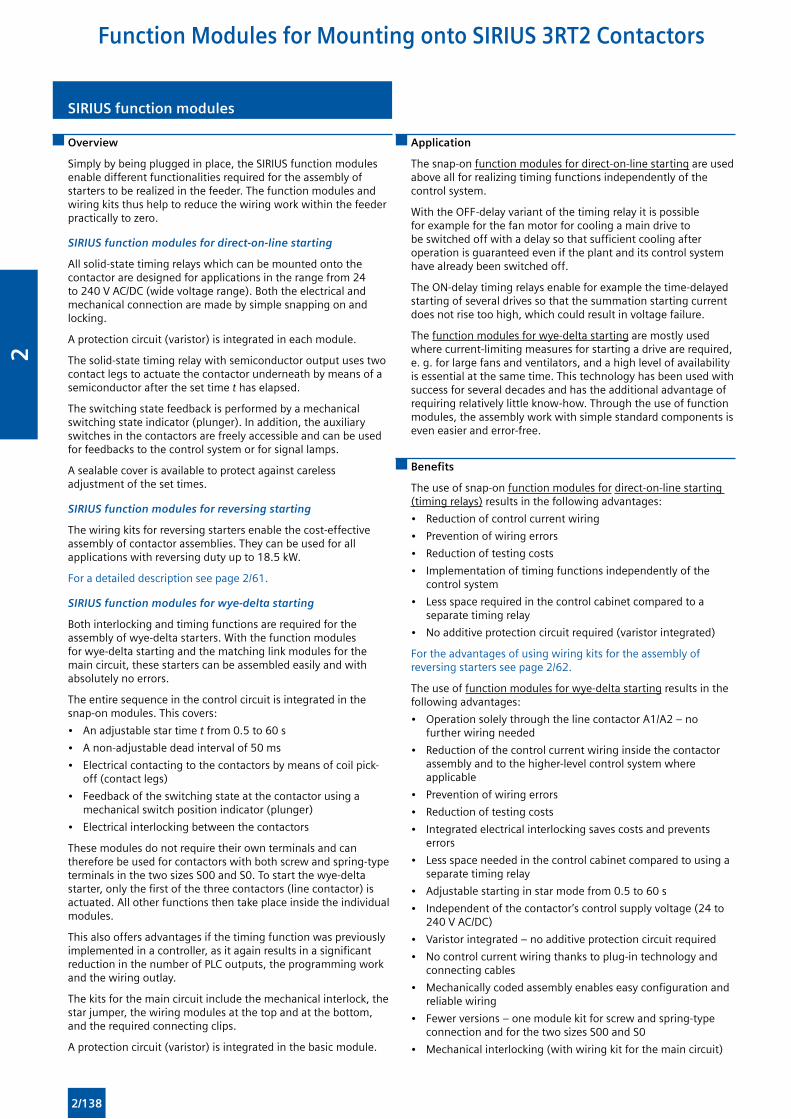
SIRIUS function modulesSIRIUS function modules
Overview
Simply by being plugged in place, the SIRIUS function modules enable different functionalities required for the assembly of starters to be realized in the feeder. The function modules and wiring kits thus help to reduce the wiring work within the feeder practically to zero.
SIRIUS function modules for direct-on-line starting
All solid-state timing relays which can be mounted onto the contactor are designed for applications in the range from 24 to 240 V AC/DC (wide voltage range). Both the electrical and mechanical connection are made by simple snapping on and locking.
A protection circuit (varistor) is integrated in each module.
The solid-state timing relay with semiconductor output uses two contact legs to actuate the contactor underneath by means of a semiconductor after the set time t has elapsed.
The switching state feedback is performed by a mechanical switching state indicator (plunger). In addition, the auxiliary switches in the contactors are freely accessible and can be used for feedbacks to the control system or for signal lamps.
A sealable cover is available to protect against careless adjustment of the set times.
SIRIUS function modules for reversing starting
The wiring kits for reversing starters enable the cost-effective assembly of contactor assemblies. They can be used for all applications with reversing duty up to 18.5 kW.
For a detailed description see page 2/61.
SIRIUS function modules for wye-delta starting
Both interlocking and timing functions are required for the assembly of wye-delta starters. With the function modules for wye-delta starting and the matching link modules for the main circuit, these starters can be assembled easily and with absolutely no errors.
The entire sequence in the control circuit is integrated in the snap-on modules. This covers:
• An adjustable star time t from 0.5 to 60 s
• A non-adjustable dead interval of 50 ms
• Electrical contacting to the contactors by means of coil pick-off (contact legs)
• Feedback of the switching state at the contactor using a mechanical switch position indicator (plunger)
• Electrical interlocking between the contactors
These modules do not require their own terminals and can therefore be used for contactors with both screw and spring-type terminals in the two sizes S00 and S0. To start the wye-delta starter, only the first of the three contactors (line contactor) is actuated. All other functions then take place inside the individual modules.
This also offers advantages if the timing function was previously implemented in a controller, as it again results in a significant reduction in the number of PLC outputs, the programming work and the wiring outlay.
The kits for the main circuit include the mechanical interlock, the star jumper, the wiring modules at the top and at the bottom, and the required connecting clips.
A protection circuit (varistor) is integrated in the basic module.
Application
The snap-on function modules for direct-on-line starting are used above all for realizing timing functions independently of the control system.
With the OFF-delay variant of the timing relay it is possible for example for the fan motor for cooling a main drive to be switched off with a delay so that sufficient cooling after operation is guaranteed even if the plant and its control system have already been switched off.
The ON-delay timing relays enable for example the time-delayed starting of several drives so that the summation starting current does not rise too high, which could result in voltage failure.
The function modules for wye-delta starting are mostly used where current-limiting measures for starting a drive are required, e. g. for large fans and ventilators, and a high level of availability is essential at the same time. This technology has been used with success for several decades and has the additional advantage of requiring relatively little know-how. Through the use of function modules, the assembly work with simple standard components is even easier and error-free.
Benefits
The use of snap-on function modules for direct-on-line starting (timing relays) results in the following advantages:
• Reduction of control current wiring
• Prevention of wiring errors
• Reduction of testing costs
• Implementation of timing functions independently of the control system
• Less space required in the control cabinet compared to a separate timing relay
• No additive protection circuit required (varistor integrated)
For the advantages of using wiring kits for the assembly of reversing starters see page 2/62.
The use of function modules for wye-delta starting results in the following advantages:
• Operation solely through the line contactor A1/A2 – no further wiring needed
• Reduction of the control current wiring inside the contactor assembly and to the higher-level control system where applicable
• Prevention of wiring errors
• Reduction of testing costs
• Integrated electrical interlocking saves costs and prevents errors
• Less space needed in the control cabinet compared to using a separate timing relay
• Adjustable starting in star mode from 0.5 to 60 s
• Independent of the contactor’s control supply voltage (24 to 240 V AC/DC)
• Varistor integrated – no additive protection circuit required
• No control current wiring thanks to plug-in technology and connecting cables
• Mechanically coded assembly enables easy configuration and reliable wiring
• Fewer versions – one module kit for screw and spring-type connection and for the two sizes S00 and S0
• Mechanical interlocking (with wiring kit for the main circuit)
Function Modules for Mounting onto SIRIUS 3RT2 Contactors
2/138
2
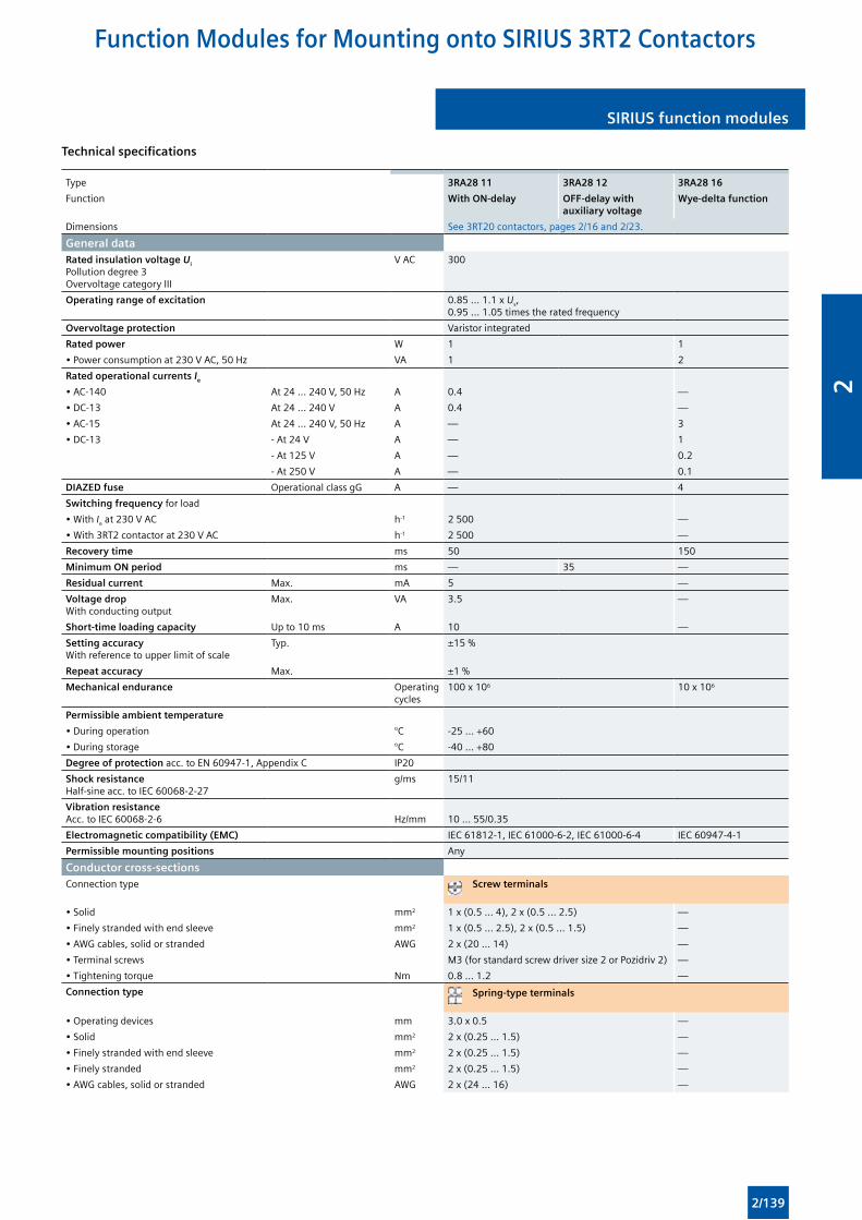
SIRIUS function modules SIRIUS function modules
Technical specifications
Type 3RA28 11 3RA28 12 3RA28 16
Function With ON-delay OFF-delay with auxiliary voltage
Wye-delta function
Dimensions See 3RT20 contactors, pages 2/16 and 2/23.
General dataRated insulation voltage Ui Pollution degree 3 Overvoltage category III
V AC 300
Operating range of excitation 0.85 ... 1.1 x Us, 0.95 ... 1.05 times the rated frequency
Overvoltage protection Varistor integrated
Rated power W 1 1
• Power consumption at 230 V AC, 50 Hz VA 1 2
Rated operational currents Ie
• AC-140 At 24 ... 240 V, 50 Hz A 0.4 —
• DC-13 At 24 ... 240 V A 0.4 —
• AC-15 At 24 ... 240 V, 50 Hz A — 3
• DC-13 - At 24 V A — 1
- At 125 V A — 0.2
- At 250 V A — 0.1
DIAZED fuse Operational class gG A — 4
Switching frequency for load
• With Ie at 230 V AC h-1 2 500 —
• With 3RT2 contactor at 230 V AC h-1 2 500 —
Recovery time ms 50 150
Minimum ON period ms — 35 —
Residual current Max. mA 5 —
Voltage drop With conducting output
Max. VA 3.5 —
Short-time loading capacity Up to 10 ms A 10 —
Setting accuracy With reference to upper limit of scale
Typ. ±15 %
Repeat accuracy Max. ±1 %
Mechanical endurance Operating cycles
100 x 106 10 x 106
Permissible ambient temperature
• During operation °C -25 ... +60
• During storage °C -40 ... +80
Degree of protection acc. to EN 60947-1, Appendix C IP20
Shock resistance Half-sine acc. to IEC 60068-2-27
g/ms 15/11
Vibration resistance Acc. to IEC 60068-2-6
Hz/mm
10 ... 55/0.35
Electromagnetic compatibility (EMC) IEC 61812-1, IEC 61000-6-2, IEC 61000-6-4 IEC 60947-4-1
Permissible mounting positions Any
Conductor cross-sectionsConnection type Screw terminals
• Solid mm2 1 x (0.5 ... 4), 2 x (0.5 ... 2.5) —
• Finely stranded with end sleeve mm2 1 x (0.5 ... 2.5), 2 x (0.5 ... 1.5) —
• AWG cables, solid or stranded AWG 2 x (20 ... 14) —
• Terminal screws M3 (for standard screw driver size 2 or Pozidriv 2) —
• Tightening torque Nm 0.8 ... 1.2 —
Connection type Spring-type terminals
• Operating devices mm 3.0 x 0.5 —
• Solid mm2 2 x (0.25 ... 1.5) —
• Finely stranded with end sleeve mm2 2 x (0.25 ... 1.5) —
• Finely stranded mm2 2 x (0.25 ... 1.5) —
• AWG cables, solid or stranded AWG 2 x (24 ... 16) —
Function Modules for Mounting onto SIRIUS 3RT2 Contactors
2/139
2
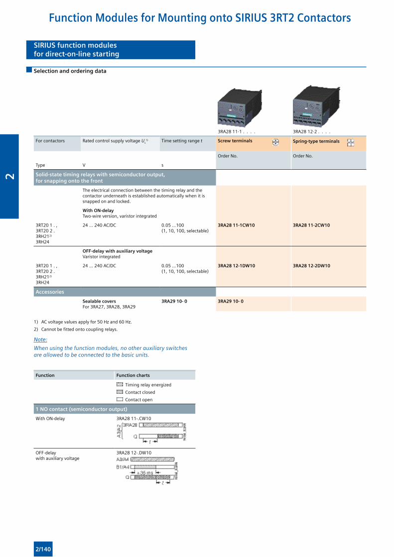
SIRIUS function modulesfor direct-on-line starting
SIRIUS function modulesfor direct-on-line starting
Selection and ordering data
3RA28 11-1 . . . . 3RA28 12-2 . . . .
For contactors Rated control supply voltage Us1) Time setting range t Screw terminals Spring-type terminals
Order No. Order No.
Type V s
Solid-state timing relays with semiconductor output, for snapping onto the front
The electrical connection between the timing relay and the contactor underneath is established automatically when it is snapped on and locked.
With ON-delayTwo-wire version, varistor integrated
3RT20 1 . , 3RT20 2 . 3RH212)
3RH24
24 ... 240 AC/DC 0.05 ...100 (1, 10, 100, selectable)
3RA28 11-1CW10 3RA28 11-2CW10
OFF-delay with auxiliary voltage Varistor integrated
3RT20 1 . , 3RT20 2 . 3RH212)
3RH24
24 ... 240 AC/DC 0.05 ...100 (1, 10, 100, selectable)
3RA28 12-1DW10 3RA28 12-2DW10
Accessories
Sealable covers For 3RA27, 3RA28, 3RA29
3RA29 10- 0 3RA29 10- 0
1) AC voltage values apply for 50 Hz and 60 Hz.
2) Cannot be fitted onto coupling relays.
Note:
When using the function modules, no other auxiliary switches are allowed to be connected to the basic units.
Function Function charts
Timing relay energized
Contact closed
Contact open
1 NO contact (semiconductor output)
With ON-delay 3RA28 11-.CW10
OFF-delay with auxiliary voltage
3RA28 12-.DW10
Function Modules for Mounting onto SIRIUS 3RT2 Contactors
2/140
2
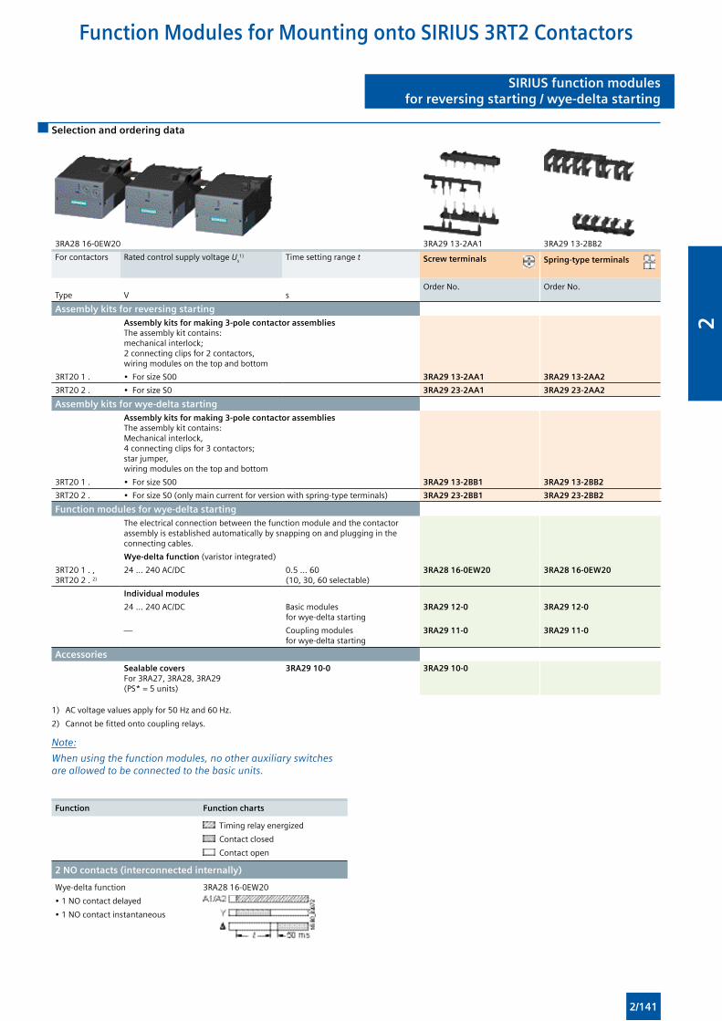
SIRIUS function modulesfor reversing starting / wye-delta starting
SIRIUS function modulesfor reversing starting / wye-delta starting
Selection and ordering data
3RA28 16-0EW20 3RA29 13-2AA1 3RA29 13-2BB2
For contactors Rated control supply voltage Us1) Time setting range t Screw terminals Spring-type terminals
Type V sOrder No. Order No.
Assembly kits for reversing startingAssembly kits for making 3-pole contactor assembliesThe assembly kit contains: mechanical interlock; 2 connecting clips for 2 contactors, wiring modules on the top and bottom
3RT20 1 . • For size S00 3RA29 13-2AA1 3RA29 13-2AA2
3RT20 2 . • For size S0 3RA29 23-2AA1 3RA29 23-2AA2
Assembly kits for wye-delta startingAssembly kits for making 3-pole contactor assembliesThe assembly kit contains: Mechanical interlock, 4 connecting clips for 3 contactors; star jumper, wiring modules on the top and bottom
3RT20 1 . • For size S00 3RA29 13-2BB1 3RA29 13-2BB2
3RT20 2 . • For size S0 (only main current for version with spring-type terminals) 3RA29 23-2BB1 3RA29 23-2BB2
Function modules for wye-delta startingThe electrical connection between the function module and the contactor assembly is established automatically by snapping on and plugging in the connecting cables.
Wye-delta function (varistor integrated)
3RT20 1 . , 3RT20 2 . 2)
24 ... 240 AC/DC 0.5 ... 60 (10, 30, 60 selectable)
3RA28 16-0EW20 3RA28 16-0EW20
Individual modules
24 ... 240 AC/DC Basic modules for wye-delta starting
3RA29 12-0 3RA29 12-0
— Coupling modules for wye-delta starting
3RA29 11-0 3RA29 11-0
AccessoriesSealable covers For 3RA27, 3RA28, 3RA29(PS* = 5 units)
3RA29 10-0 3RA29 10-0
1) AC voltage values apply for 50 Hz and 60 Hz.
2) Cannot be fitted onto coupling relays.
Note:
When using the function modules, no other auxiliary switches are allowed to be connected to the basic units.
Function Function charts
Timing relay energized
Contact closed
Contact open
2 NO contacts (interconnected internally)
Wye-delta function
• 1 NO contact delayed
• 1 NO contact instantaneous
3RA28 16-0EW20
Function Modules for Mounting onto SIRIUS 3RT2 Contactors
2/141
2
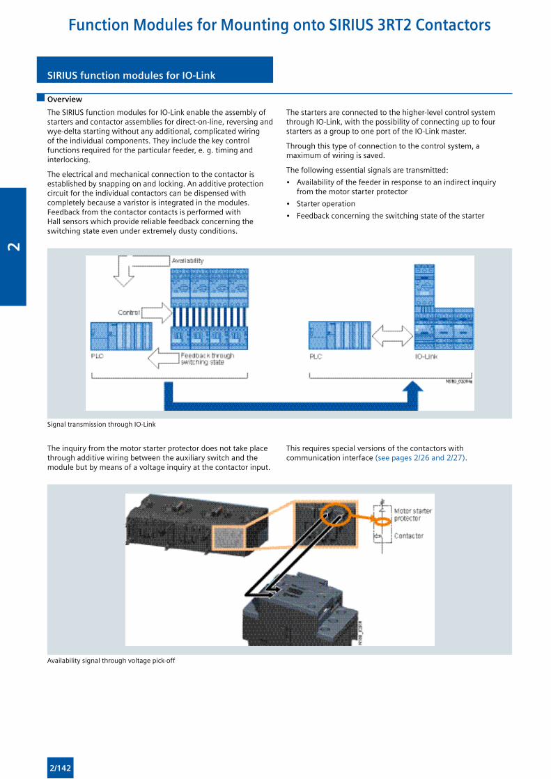
SIRIUS function modules for IO-LinkSIRIUS function modules for IO-Link
The SIRIUS function modules for IO-Link enable the assembly of starters and contactor assemblies for direct-on-line, reversing and wye-delta starting without any additional, complicated wiring of the individual components. They include the key control functions required for the particular feeder, e. g. timing and interlocking.
The electrical and mechanical connection to the contactor is established by snapping on and locking. An additive protection circuit for the individual contactors can be dispensed with completely because a varistor is integrated in the modules. Feedback from the contactor contacts is performed with Hall sensors which provide reliable feedback concerning the switching state even under extremely dusty conditions.
Overview
The starters are connected to the higher-level control system through IO-Link, with the possibility of connecting up to four starters as a group to one port of the IO-Link master.
Through this type of connection to the control system, a maximum of wiring is saved.
The following essential signals are transmitted:
• Availability of the feeder in response to an indirect inquiry from the motor starter protector
• Starter operation
• Feedback concerning the switching state of the starter
Signal transmission through IO-Link
The inquiry from the motor starter protector does not take place through additive wiring between the auxiliary switch and the module but by means of a voltage inquiry at the contactor input.
This requires special versions of the contactors with communication interface (see pages 2/26 and 2/27).
Availability signal through voltage pick-off
Function Modules for Mounting onto SIRIUS 3RT2 Contactors
2/142
2
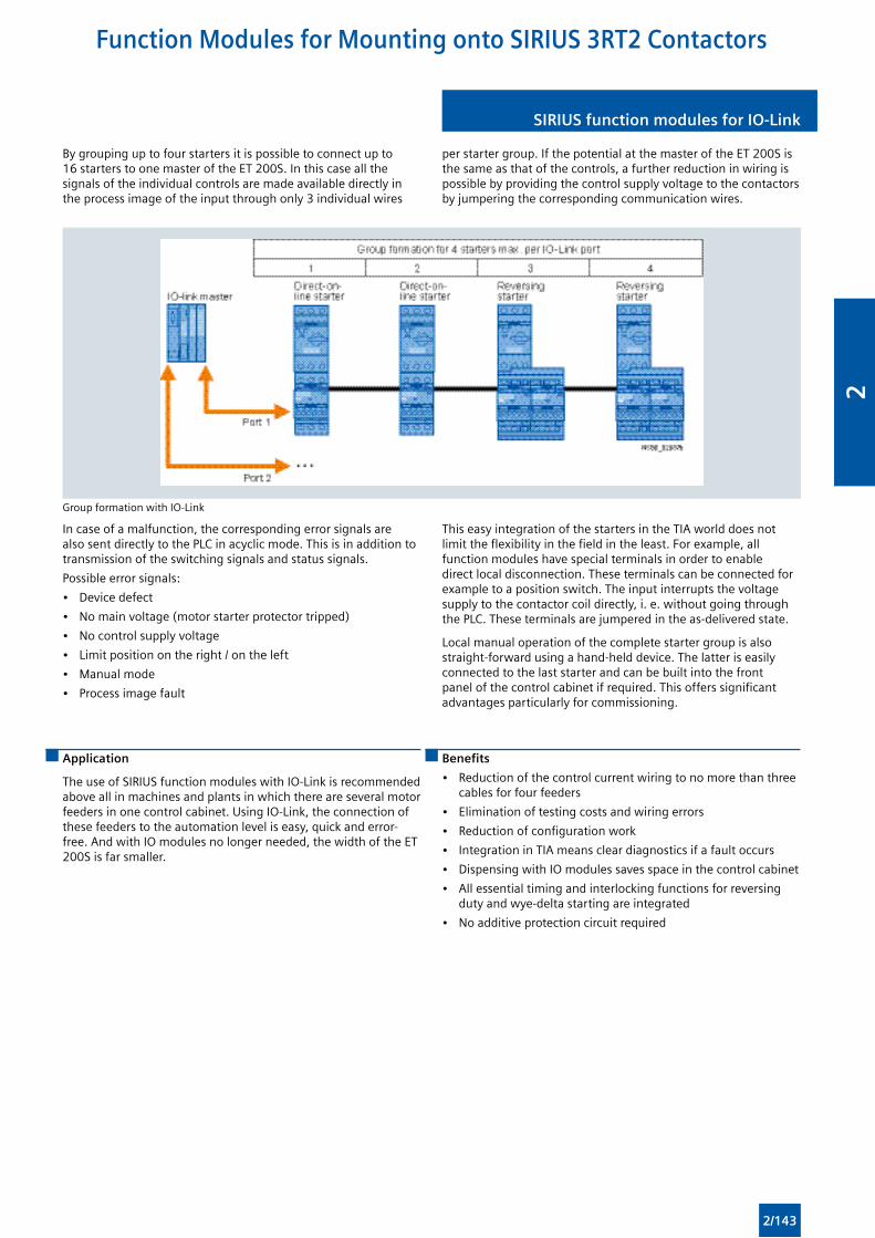
SIRIUS function modules for IO-Link SIRIUS function modules for IO-Link
By grouping up to four starters it is possible to connect up to 16 starters to one master of the ET 200S. In this case all the signals of the individual controls are made available directly in the process image of the input through only 3 individual wires
per starter group. If the potential at the master of the ET 200S is the same as that of the controls, a further reduction in wiring is possible by providing the control supply voltage to the contactors by jumpering the corresponding communication wires.
Group formation with IO-Link
In case of a malfunction, the corresponding error signals are also sent directly to the PLC in acyclic mode. This is in addition to transmission of the switching signals and status signals.
Possible error signals:
• Device defect
• No main voltage (motor starter protector tripped)
• No control supply voltage
• Limit position on the right / on the left
• Manual mode
• Process image fault
This easy integration of the starters in the TIA world does not limit the flexibility in the field in the least. For example, all function modules have special terminals in order to enable direct local disconnection. These terminals can be connected for example to a position switch. The input interrupts the voltage supply to the contactor coil directly, i. e. without going through the PLC. These terminals are jumpered in the as-delivered state.
Local manual operation of the complete starter group is also straight-forward using a hand-held device. The latter is easily connected to the last starter and can be built into the front panel of the control cabinet if required. This offers significant advantages particularly for commissioning.
Application
The use of SIRIUS function modules with IO-Link is recommended above all in machines and plants in which there are several motor feeders in one control cabinet. Using IO-Link, the connection of these feeders to the automation level is easy, quick and error-free. And with IO modules no longer needed, the width of the ET 200S is far smaller.
Benefits
• Reduction of the control current wiring to no more than three cables for four feeders
• Elimination of testing costs and wiring errors
• Reduction of configuration work
• Integration in TIA means clear diagnostics if a fault occurs
• Dispensing with IO modules saves space in the control cabinet
• All essential timing and interlocking functions for reversing duty and wye-delta starting are integrated
• No additive protection circuit required
Function Modules for Mounting onto SIRIUS 3RT2 Contactors
2/143
2
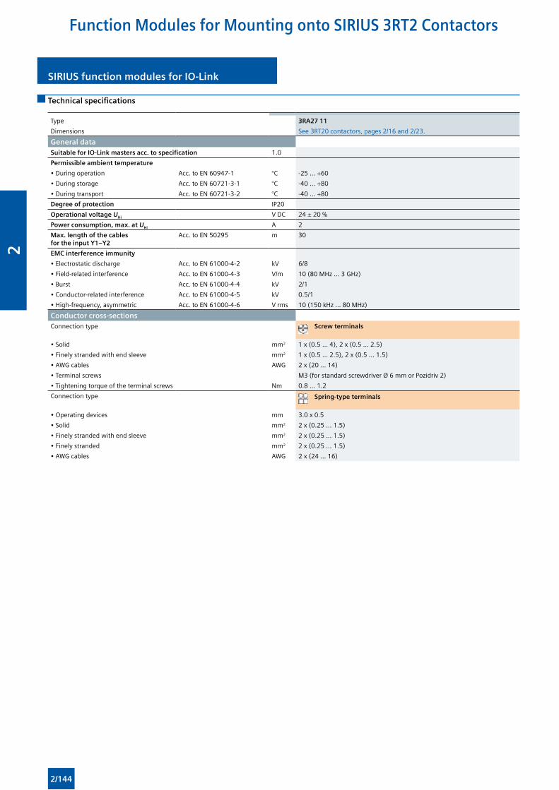
SIRIUS function modules for IO-LinkSIRIUS function modules for IO-Link
Technical specifications
Type 3RA27 11
Dimensions See 3RT20 contactors, pages 2/16 and 2/23.
General dataSuitable for IO-Link masters acc. to specification 1.0
Permissible ambient temperature
• During operation Acc. to EN 60947-1 °C -25 ... +60
• During storage Acc. to EN 60721-3-1 °C -40 ... +80
• During transport Acc. to EN 60721-3-2 °C -40 ... +80
Degree of protection IP20
Operational voltage UHi V DC 24 ± 20 %
Power consumption, max. at UHi A 2
Max. length of the cables for the input Y1–Y2
Acc. to EN 50295 m 30
EMC interference immunity
• Electrostatic discharge Acc. to EN 61000-4-2 kV 6/8
• Field-related interference Acc. to EN 61000-4-3 V/m 10 (80 MHz ... 3 GHz)
• Burst Acc. to EN 61000-4-4 kV 2/1
• Conductor-related interference Acc. to EN 61000-4-5 kV 0.5/1
• High-frequency, asymmetric Acc. to EN 61000-4-6 V rms 10 (150 kHz ... 80 MHz)
Conductor cross-sectionsConnection type Screw terminals
• Solid mm2 1 x (0.5 ... 4), 2 x (0.5 ... 2.5)
• Finely stranded with end sleeve mm2 1 x (0.5 ... 2.5), 2 x (0.5 ... 1.5)
• AWG cables AWG 2 x (20 ... 14)
• Terminal screws M3 (for standard screwdriver Ø 6 mm or Pozidriv 2)
• Tightening torque of the terminal screws Nm 0.8 ... 1.2
Connection type Spring-type terminals
• Operating devices mm 3.0 x 0.5
• Solid mm2 2 x (0.25 ... 1.5)
• Finely stranded with end sleeve mm2 2 x (0.25 ... 1.5)
• Finely stranded mm2 2 x (0.25 ... 1.5)
• AWG cables AWG 2 x (24 ... 16)
Function Modules for Mounting onto SIRIUS 3RT2 Contactors
2/144
2
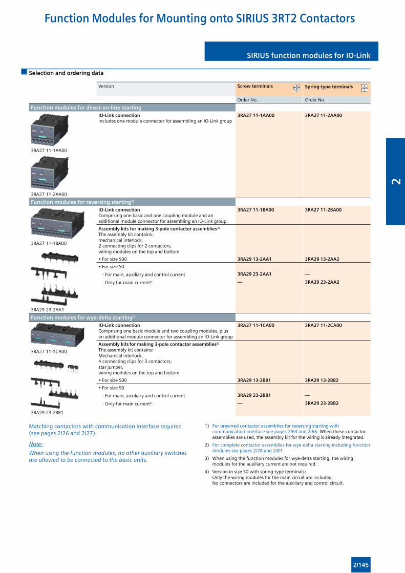
SIRIUS function modules for IO-Link SIRIUS function modules for IO-Link
Selection and ordering data
Version Screw terminals Spring-type terminals
Order No. Order No.
Function modules for direct-on-line starting
3RA27 11-1AA00
3RA27 11-2AA00
IO-Link connectionIncludes one module connector for assembling an IO-Link group
3RA27 11-1AA00 3RA27 11-2AA00
Function modules for reversing starting1)
3RA27 11-1BA00
3RA29 23-2AA1
IO-Link connection Comprising one basic and one coupling module and an additional module connector for assembling an IO-Link group
3RA27 11-1BA00 3RA27 11-2BA00
Assembly kits for making 3-pole contactor assemblies3)
The assembly kit contains: mechanical interlock; 2 connecting clips for 2 contactors, wiring modules on the top and bottom
• For size S00 3RA29 13-2AA1 3RA29 13-2AA2
• For size S0
- For main, auxiliary and control current 3RA29 23-2AA1 —
- Only for main current4) — 3RA29 23-2AA2
Function modules for wye-delta starting2)
3RA27 11-1CA00
3RA29 23-2BB1
IO-Link connection Comprising one basic module and two coupling modules, plus an additional module connector for assembling an IO-Link group
3RA27 11-1CA00 3RA27 11-2CA00
Assembly kits for making 3-pole contactor assemblies3)
The assembly kit contains: Mechanical interlock, 4 connecting clips for 3 contactors; star jumper, wiring modules on the top and bottom
• For size S00 3RA29 13-2BB1 3RA29 13-2BB2
• For size S0
- For main, auxiliary and control current 3RA29 23-2BB1 —
- Only for main current4) — 3RA29 23-2BB2
Matching contactors with communication interface required (see pages 2/26 and 2/27).
Note:
When using the function modules, no other auxiliary switches are allowed to be connected to the basic units.
1) For prewired contactor assemblies for reversing starting with communication interface see pages 2/64 and 2/66. When these contactor assemblies are used, the assembly kit for the wiring is already integrated.
2) For complete contactor assemblies for wye-delta starting including function modules see pages 2/78 and 2/81.
3) When using the function modules for wye-delta starting, the wiring modules for the auxiliary current are not required.
4) Version in size S0 with spring-type terminals: Only the wiring modules for the main circuit are included. No connectors are included for the auxiliary and control circuit.
Function Modules for Mounting onto SIRIUS 3RT2 Contactors
2/145
2
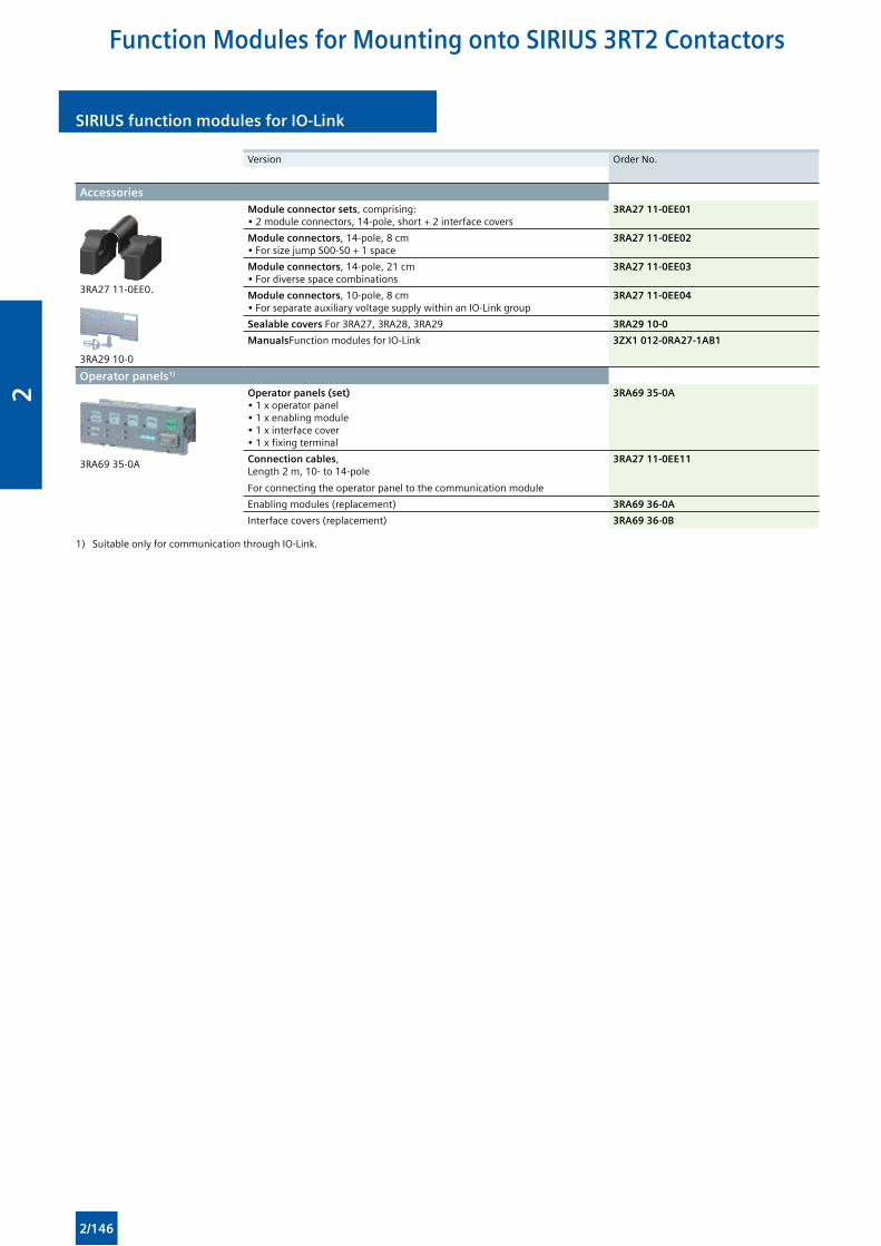
SIRIUS function modules for IO-LinkSIRIUS function modules for IO-Link
Version Order No.
Accessories
3RA27 11-0EE0.
3RA29 10-0
Module connector sets, comprising:• 2 module connectors, 14-pole, short + 2 interface covers
3RA27 11-0EE01
Module connectors, 14-pole, 8 cm• For size jump S00-S0 + 1 space
3RA27 11-0EE02
Module connectors, 14-pole, 21 cm• For diverse space combinations
3RA27 11-0EE03
Module connectors, 10-pole, 8 cm• For separate auxiliary voltage supply within an IO-Link group
3RA27 11-0EE04
Sealable covers For 3RA27, 3RA28, 3RA29 3RA29 10-0
ManualsFunction modules for IO-Link 3ZX1 012-0RA27-1AB1
Operator panels1)
3RA69 35-0A
Operator panels (set)• 1 x operator panel• 1 x enabling module• 1 x interface cover• 1 x fixing terminal
3RA69 35-0A
Connection cables, Length 2 m, 10- to 14-pole
For connecting the operator panel to the communication module
3RA27 11-0EE11
Enabling modules (replacement) 3RA69 36-0A
Interface covers (replacement) 3RA69 36-0B
1) Suitable only for communication through IO-Link.
Function Modules for Mounting onto SIRIUS 3RT2 Contactors
2/146
2
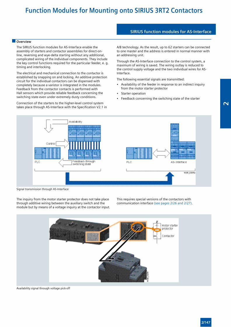
SIRIUS function modules for AS-Interface SIRIUS function modules for AS-Interface
Overview
The SIRIUS function modules for AS-Interface enable the assembly of starters and contactor assemblies for direct-on-line, reversing and wye-delta starting without any additional, complicated wiring of the individual components. They include the key control functions required for the particular feeder, e. g. timing and interlocking.
The electrical and mechanical connection to the contactor is established by snapping on and locking. An additive protection circuit for the individual contactors can be dispensed with completely because a varistor is integrated in the modules. Feedback from the contactor contacts is performed with Hall sensors which provide reliable feedback concerning the switching state even under extremely dusty conditions.
Connection of the starters to the higher-level control system takes place through AS-Interface with the Specification V2.1 in
A/B technology. As the result, up to 62 starters can be connected to one master and the address is entered in normal manner with an addressing unit.
Through the AS-Interface connection to the control system, a maximum of wiring is saved. The wiring outlay is reduced to the control supply voltage and the two individual wires for AS-Interface.
The following essential signals are transmitted:
• Availability of the feeder in response to an indirect inquiry from the motor starter protector
• Starter operation
• Feedback concerning the switching state of the starter
Signal transmission through AS-Interface
The inquiry from the motor starter protector does not take place through additive wiring between the auxiliary switch and the module but by means of a voltage inquiry at the contactor input.
This requires special versions of the contactors with communication interface (see pages 2/26 and 2/27).
Availability signal through voltage pick-off
Function Modules for Mounting onto SIRIUS 3RT2 Contactors
2/147
2
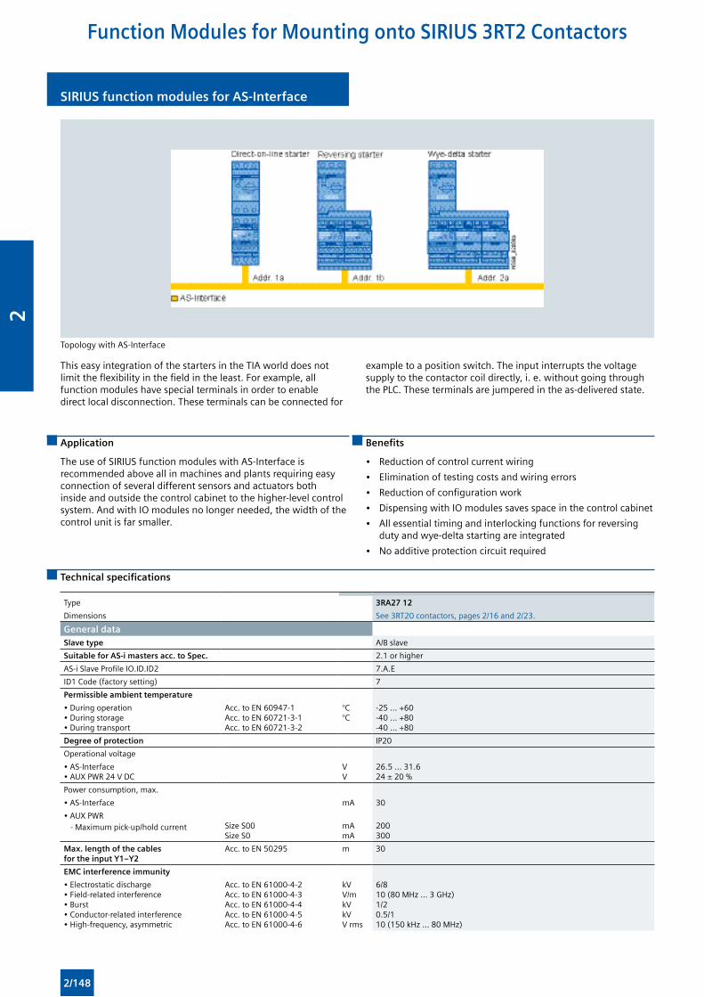
SIRIUS function modules for AS-InterfaceSIRIUS function modules for AS-Interface
Topology with AS-Interface
This easy integration of the starters in the TIA world does not limit the flexibility in the field in the least. For example, all function modules have special terminals in order to enable direct local disconnection. These terminals can be connected for
example to a position switch. The input interrupts the voltage supply to the contactor coil directly, i. e. without going through the PLC. These terminals are jumpered in the as-delivered state.
Application
The use of SIRIUS function modules with AS-Interface is recommended above all in machines and plants requiring easy connection of several different sensors and actuators both inside and outside the control cabinet to the higher-level control system. And with IO modules no longer needed, the width of the control unit is far smaller.
Benefits
• Reduction of control current wiring
• Elimination of testing costs and wiring errors
• Reduction of configuration work
• Dispensing with IO modules saves space in the control cabinet
• All essential timing and interlocking functions for reversing duty and wye-delta starting are integrated
• No additive protection circuit required
Technical specifications
Type 3RA27 12
Dimensions See 3RT20 contactors, pages 2/16 and 2/23.
General dataSlave type A/B slave
Suitable for AS-i masters acc. to Spec. 2.1 or higher
AS-i Slave Profile IO.ID.ID2 7.A.E
ID1 Code (factory setting) 7
Permissible ambient temperature
• During operation• During storage• During transport
Acc. to EN 60947-1Acc. to EN 60721-3-1Acc. to EN 60721-3-2
°C°C
-25 ... +60-40 ... +80-40 ... +80
Degree of protection IP20
Operational voltage
• AS-Interface• AUX PWR 24 V DC
VV
26.5 ... 31.624 ± 20 %
Power consumption, max.
• AS-Interface mA 30
• AUX PWR - Maximum pick-up/hold current
Size S00Size S0
mAmA
200300
Max. length of the cables for the input Y1–Y2
Acc. to EN 50295 m 30
EMC interference immunity
• Electrostatic discharge• Field-related interference• Burst• Conductor-related interference• High-frequency, asymmetric
Acc. to EN 61000-4-2Acc. to EN 61000-4-3Acc. to EN 61000-4-4Acc. to EN 61000-4-5Acc. to EN 61000-4-6
kVV/mkVkVV rms
6/810 (80 MHz ... 3 GHz)1/20.5/110 (150 kHz ... 80 MHz)
Function Modules for Mounting onto SIRIUS 3RT2 Contactors
2/148
2
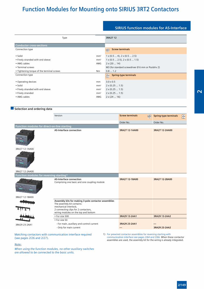
SIRIUS function modules for AS-Interface SIRIUS function modules for AS-Interface
Type 3RA27 12
Conductor cross-sectionsConnection type Screw terminals
• Solid mm2 1 x (0.5 ... 4), 2 x (0.5 ... 2.5)
• Finely stranded with end sleeve mm2 1 x (0.5 ... 2.5), 2 x (0.5 ... 1.5)
• AWG cables AWG 2 x (20 ... 14)
• Terminal screws M3 (for standard screwdriver Ø 6 mm or Pozidriv 2)
• Tightening torque of the terminal screws Nm 0.8 ... 1.2
Connection type Spring-type terminals
• Operating devices mm 3.0 x 0.5
• Solid mm2 2 x (0.25 ... 1.5)
• Finely stranded with end sleeve mm2 2 x (0.25 ... 1.5)
• Finely stranded mm2 2 x (0.25 ... 1.5)
• AWG cables AWG 2 x (24 ... 16)
Selection and ordering data
Version Screw terminals Spring-type terminals
Order No. Order No.
Function modules for direct-on-line starting
3RA27 12-1AA00
3RA27 12-2AA00
AS-Interface connection 3RA27 12-1AA00 3RA27 12-2AA00
Function modules for reversing starting1)
3RA27 12-1BA00
AS-Interface connectionComprising one basic and one coupling module
3RA27 12-1BA00 3RA27 12-2BA00
3RA29 23-2AA1
Assembly kits for making 3-pole contactor assembliesThe assembly kit contains: mechanical interlock; 2 connecting clips for 2 contactors, wiring modules on the top and bottom
• For size S00 3RA29 13-2AA1 3RA29 13-2AA2
• For size S0
- For main, auxiliary and control current 3RA29 23-2AA1 —
- Only for main current — 3RA29 23-2AA2
Matching contactors with communication interface required (see pages 2/26 and 2/27).
Note:
When using the function modules, no other auxiliary switches are allowed to be connected to the basic units.
1) For prewired contactor assemblies for reversing starting with communication interface see pages 2/64 and 2/66. When these contactor assemblies are used, the assembly kit for the wiring is already integrated.
Function Modules for Mounting onto SIRIUS 3RT2 Contactors
2/149
2
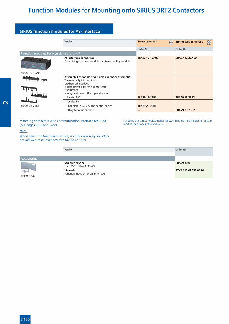
SIRIUS function modules for AS-InterfaceSIRIUS function modules for AS-Interface
Version Screw terminals Spring-type terminals
Order No. Order No.
Function modules for wye-delta starting1)
3RA27 12-1CA00
AS-Interface connectionComprising one basic module and two coupling modules
3RA27 12-1CA00 3RA27 12-2CA00
3RA29 23-2BB1
Assembly kits for making 3-pole contactor assembliesThe assembly kit contains: Mechanical interlock, 4 connecting clips for 3 contactors; star jumper, wiring modules on the top and bottom
• For size S00 3RA29 13-2BB1 3RA29 13-2BB2
• For size S0
- For main, auxiliary and control current 3RA29 23-2BB1 —
- Only for main current — 3RA29 23-2BB2
Matching contactors with communication interface required (see pages 2/26 and 2/27).
Note:
When using the function modules, no other auxiliary switches are allowed to be connected to the basic units.
1) For complete contactor assemblies for wye-delta starting including function modules see pages 2/64 and 2/66.
Version Order No.
Accessories
3RA29 10-0
Sealable covers For 3RA27, 3RA28, 3RA29
3RA29 10-0
Manuals Function modules for AS-Interface
3ZX1 012-0RA27-0AB0
Function Modules for Mounting onto SIRIUS 3RT2 Contactors
2/150
2
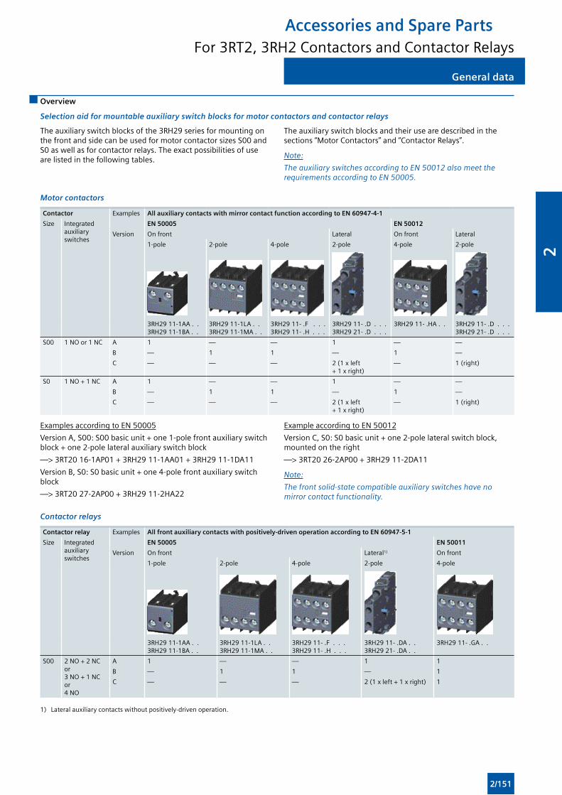
General dataGeneral data
Accessories and Spare PartsFor 3RT2, 3RH2 Contactors and Contactor Relays
Overview
Selection aid for mountable auxiliary switch blocks for motor contactors and contactor relays
The auxiliary switch blocks of the 3RH29 series for mounting on the front and side can be used for motor contactor sizes S00 and S0 as well as for contactor relays. The exact possibilities of use are listed in the following tables.
The auxiliary switch blocks and their use are described in the sections “Motor Contactors” and “Contactor Relays”.
Note:
The auxiliary switches according to EN 50012 also meet the requirements according to EN 50005.
Motor contactors
Contactor Examples All auxiliary contacts with mirror contact function according to EN 60947-4-1
Size Integrated auxiliary switches
EN 50005 EN 50012
Version On front Lateral On front Lateral
1-pole 2-pole 4-pole 2-pole 4-pole 2-pole
3RH29 11-1AA . . 3RH29 11-1BA . .
3RH29 11-1LA . . 3RH29 11-1MA . .
3RH29 11- .F . . . 3RH29 11- .H . . .
3RH29 11- .D . . . 3RH29 21- .D . . .
3RH29 11- .HA . . 3RH29 11- .D . . . 3RH29 21- .D . . .
S00 1 NO or 1 NC A 1 — — 1 — —
B — 1 1 — 1 —
C — — — 2 (1 x left + 1 x right)
— 1 (right)
S0 1 NO + 1 NC A 1 — — 1 — —
B — 1 1 — 1 —
C — — — 2 (1 x left + 1 x right)
— 1 (right)
Examples according to EN 50005
Version A, S00: S00 basic unit + one 1-pole front auxiliary switch block + one 2-pole lateral auxiliary switch block
—> 3RT20 16-1AP01 + 3RH29 11-1AA01 + 3RH29 11-1DA11
Version B, S0: S0 basic unit + one 4-pole front auxiliary switch block
—> 3RT20 27-2AP00 + 3RH29 11-2HA22
Example according to EN 50012
Version C, S0: S0 basic unit + one 2-pole lateral switch block, mounted on the right
—> 3RT20 26-2AP00 + 3RH29 11-2DA11
Note:
The front solid-state compatible auxiliary switches have no mirror contact functionality.
Contactor relays
Contactor relay Examples All front auxiliary contacts with positively-driven operation according to EN 60947-5-1
Size Integrated auxiliary switches
EN 50005 EN 50011
Version On front Lateral1) On front
1-pole 2-pole 4-pole 2-pole 4-pole
3RH29 11-1AA . . 3RH29 11-1BA . .
3RH29 11-1LA . . 3RH29 11-1MA . .
3RH29 11- .F . . . 3RH29 11- .H . . .
3RH29 11- .DA . . 3RH29 21- .DA . .
3RH29 11- .GA . .
S00 2 NO + 2 NC or 3 NO + 1 NC or 4 NO
A 1 — — 1 1
B — 1 1 — 1
C — — — 2 (1 x left + 1 x right) 1
1) Lateral auxiliary contacts without positively-driven operation.
2/151
2
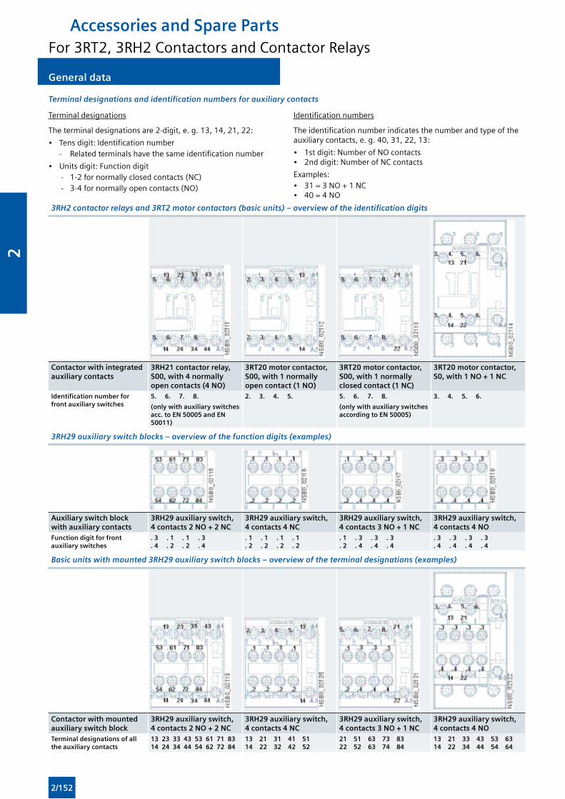
General data General data
Terminal designations and identification numbers for auxiliary contacts
Terminal designations
The terminal designations are 2-digit, e. g. 13, 14, 21, 22:
• Tens digit: Identification number - Related terminals have the same identification number
• Units digit: Function digit - 1-2 for normally closed contacts (NC) - 3-4 for normally open contacts (NO)
Identification numbers
The identification number indicates the number and type of the auxiliary contacts, e. g. 40, 31, 22, 13:
• 1st digit: Number of NO contacts• 2nd digit: Number of NC contacts
Examples:• 31 = 3 NO + 1 NC• 40 = 4 NO
3RH2 contactor relays and 3RT2 motor contactors (basic units) – overview of the identification digits
Contactor with integrated auxiliary contacts
3RH21 contactor relay, S00, with 4 normally open contacts (4 NO)
3RT20 motor contactor, S00, with 1 normally open contact (1 NO)
3RT20 motor contactor, S00, with 1 normally closed contact (1 NC)
3RT20 motor contactor, S0, with 1 NO + 1 NC
Identification number for front auxiliary switches
5. 6. 7. 8. 2. 3. 4. 5. 5. 6. 7. 8. 3. 4. 5. 6.
(only with auxiliary switches acc. to EN 50005 and EN 50011)
(only with auxiliary switches according to EN 50005)
3RH29 auxiliary switch blocks – overview of the function digits (examples)
Auxiliary switch block with auxiliary contacts
3RH29 auxiliary switch, 4 contacts 2 NO + 2 NC
3RH29 auxiliary switch, 4 contacts 4 NC
3RH29 auxiliary switch, 4 contacts 3 NO + 1 NC
3RH29 auxiliary switch, 4 contacts 4 NO
Function digit for front auxiliary switches
. 3 . 1 . 1 . 3
. 4 . 2 . 2 . 4. 1 . 1 . 1 . 1. 2 . 2 . 2 . 2
. 1 . 3 . 3 . 3
. 2 . 4 . 4 . 4. 3 . 3 . 3 . 3. 4 . 4 . 4 . 4
Basic units with mounted 3RH29 auxiliary switch blocks – overview of the terminal designations (examples)
Contactor with mounted auxiliary switch block
3RH29 auxiliary switch, 4 contacts 2 NO + 2 NC
3RH29 auxiliary switch, 4 contacts 4 NC
3RH29 auxiliary switch, 4 contacts 3 NO + 1 NC
3RH29 auxiliary switch, 4 contacts 4 NO
Terminal designations of all the auxiliary contacts
13 23 33 43 53 61 71 8314 24 34 44 54 62 72 84
13 21 31 41 5114 22 32 42 52
21 51 63 73 8322 52 63 74 84
13 21 33 43 53 6314 22 34 44 54 64
Accessories and Spare PartsFor 3RT2, 3RH2 Contactors and Contactor Relays
2/152
2
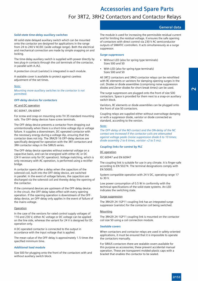
General dataGeneral data
Solid-state time-delay auxiliary switches
All solid-state delayed auxiliary switch which can be mounted onto the contactor are designed for applications in the range from 24 to 240 V AC/DC (wide voltage range). Both the electrical and mechanical connection are made by simple snapping on and locking.
The time-delay auxiliary switch is supplied with power directly by two plug-in contacts through the coil terminals of the contactor, in parallel with A./A2.
A protection circuit (varistor) is integrated in each module.
A sealable cover is available to protect against careless adjustment of the set times.
Note:
Mounting more auxiliary switches to the contactor is not permitted.
OFF-delay devices for contactors
AC and DC operation
IEC 60947, EN 60947
For screw and snap-on mounting onto TH 35 standard mounting rails. The OFF-delay devices have screw terminals.
The OFF-delay device prevents a contactor from dropping out unintentionally when there is a short-time voltage dip or voltage failure. It supplies a downstream, DC-operated contactor with the necessary energy during a voltage dip, ensuring that the contactor does not trip. The 3RA29 16 OFF-delay devices are specifically designed for operation with the 3RT contactors and 3RH contactor relays in the SIRIUS series.
The OFF-delay device operates without external voltage on a capacitive basis, and can be energized with either AC or DC (24 V version only for DC operation). Voltage matching, which is only necessary with AC operation, is performed using a rectifier bridge.
A contactor opens after a delay when the capacitors of the solenoid coil, built into the OFF-delay device, are switched in parallel. In the event of voltage failures, the capacitors are discharged via the solenoid coil and thereby delay the opening of the contactor.
If the command devices are upstream of the OFF-delay device in the circuit, the OFF-delay takes effect with every opening operation. If the opening operation is downstream of the OFF-delay device, an OFF-delay only applies in the event of failure of the mains voltage.
Operation
In the case of the versions for rated control supply voltages of 110 and 230 V, either AC voltage or DC voltage can be applied on the line side, whereas the variant for 24 V is designed for DC operation only.
A DC-operated contactor is connected to the output in accordance with the input voltage that is applied.
The mean value of the OFF-delay is approximately 1.5 times the specified minimum time.
Additional load module
Size S00 for plugging onto the front of the contactors with and without auxiliary switch block.
The module is used for increasing the permissible residual current and for limiting the residual voltage. It ensures the safe opening of contactors with direct control via 230 V AC semiconductor outputs of SIMATIC controllers. It acts simultaneously as a surge suppressor.
Surge suppressors
• Without LED (also for spring-type terminals) Sizes S00 and S0
• With LED (also for spring-type terminals) Sizes S00 and S0
All 3RT2 contactors and 3RH2 contactor relays can be retrofitted with RC elements or varistors for damping opening surges in the coil. Diodes or diode assemblies (comprising noise suppression diodes and Zener diodes for short break times) can be used.
The surge suppressors are plugged onto the front of size S00 contactors. Space is provided for them next to a snap-on auxiliary switch block.
Varistors, RC elements or diode assemblies can be plugged onto the front of size S0 contactors.
Coupling relays are supplied either without overvoltage damping or with a suppressor diode, varistor or diode connected as standard, according to the version.
Note:
The OFF-delay of the NO contact and the ON-delay of the NC contact are increased if the contactor coils are attenuated against voltage peaks (noise suppression diode 6 to 10 times; diode assembly 2 to 6 times, varistor +2 to 5 ms).
Coupling links for control by PLC
DC operation
IEC 60947 and EN 60947
The coupling link is suitable for use in any climate. It is finger-safe according to EN 50274. The terminal designations comply with EN 50005.
System-compatible operation with 24 V DC, operating range 17 to 30 V.
Low power consumption of 0.5 W in conformity with the technical specifications of the solid-state systems. An LED indicates the switching state.
Surge suppression
The 3RH29 24-1GP11 coupling link has an integrated surge suppressor (varistor) for the contactor coil being switched.
Mounting
The 3RH29 24-1GP11 coupling link is mounted on the contactor coil size S0 using a coil connection module.
Sealable covers
When contactors and contactor relays are used in safety-oriented applications, it must be ensured that it is impossible to operate the contactors manually.
For SIRIUS contactors there are sealable covers available for this purpose as accessories; these prevent accidental manual operation. These are transparent molded-plastic caps with a bracket that enables the contactor to be sealed.
Accessories and Spare PartsFor 3RT2, 3RH2 Contactors and Contactor Relays
2/153
2
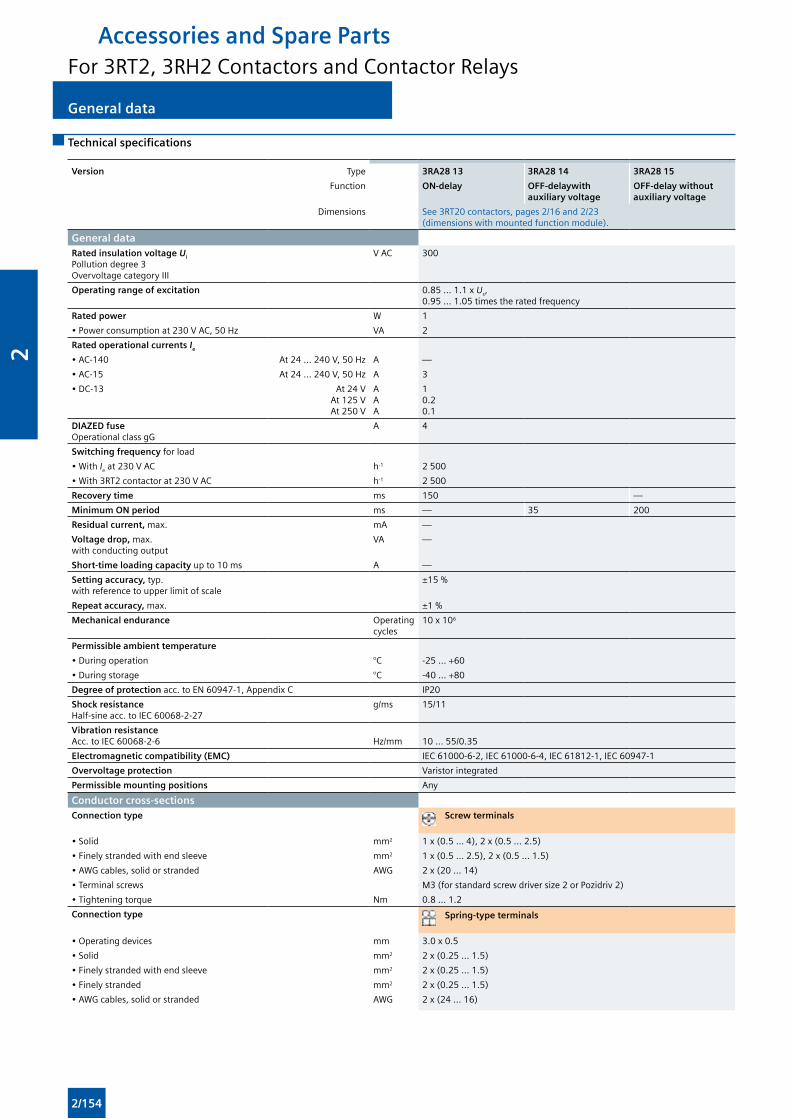
General data General data
Technical specifications
Version Type 3RA28 13 3RA28 14 3RA28 15
Function ON-delay OFF-delaywith auxiliary voltage
OFF-delay without auxiliary voltage
Dimensions See 3RT20 contactors, pages 2/16 and 2/23 (dimensions with mounted function module).
General dataRated insulation voltage Ui Pollution degree 3 Overvoltage category III
V AC 300
Operating range of excitation 0.85 ... 1.1 x Us, 0.95 ... 1.05 times the rated frequency
Rated power W 1
• Power consumption at 230 V AC, 50 Hz VA 2
Rated operational currents Ie
• AC-140 At 24 ... 240 V, 50 Hz A —
• AC-15 At 24 ... 240 V, 50 Hz A 3
• DC-13 At 24 VAt 125 VAt 250 V
AAA
10.20.1
DIAZED fuseOperational class gG
A 4
Switching frequency for load
• With Ie at 230 V AC h-1 2 500
• With 3RT2 contactor at 230 V AC h-1 2 500
Recovery time ms 150 —
Minimum ON period ms — 35 200
Residual current, max. mA —
Voltage drop, max. with conducting output
VA —
Short-time loading capacity up to 10 ms A —
Setting accuracy, typ. with reference to upper limit of scale
±15 %
Repeat accuracy, max. ±1 %
Mechanical endurance Operating cycles
10 x 106
Permissible ambient temperature
• During operation °C -25 ... +60
• During storage °C -40 ... +80
Degree of protection acc. to EN 60947-1, Appendix C IP20
Shock resistance Half-sine acc. to IEC 60068-2-27
g/ms 15/11
Vibration resistance Acc. to IEC 60068-2-6
Hz/mm
10 ... 55/0.35
Electromagnetic compatibility (EMC) IEC 61000-6-2, IEC 61000-6-4, IEC 61812-1, IEC 60947-1
Overvoltage protection Varistor integrated
Permissible mounting positions Any
Conductor cross-sectionsConnection type Screw terminals
• Solid mm2 1 x (0.5 ... 4), 2 x (0.5 ... 2.5)
• Finely stranded with end sleeve mm2 1 x (0.5 ... 2.5), 2 x (0.5 ... 1.5)
• AWG cables, solid or stranded AWG 2 x (20 ... 14)
• Terminal screws M3 (for standard screw driver size 2 or Pozidriv 2)
• Tightening torque Nm 0.8 ... 1.2
Connection type Spring-type terminals
• Operating devices mm 3.0 x 0.5
• Solid mm2 2 x (0.25 ... 1.5)
• Finely stranded with end sleeve mm2 2 x (0.25 ... 1.5)
• Finely stranded mm2 2 x (0.25 ... 1.5)
• AWG cables, solid or stranded AWG 2 x (24 ... 16)
Accessories and Spare PartsFor 3RT2, 3RH2 Contactors and Contactor Relays
2/154
2
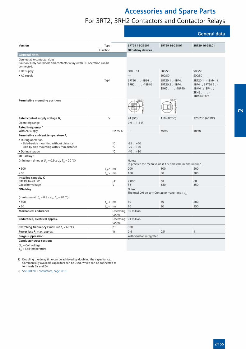
General dataGeneral data
Version Type 3RT29 16-2BE01 3RT29 16-2BK01 3RT29 16-2BL01
Function OFF-delay devices
General dataConnectable contactor sizesCaution! Only contactors and contactor relays with DC operation can be connected.
• DC supply S00 ...S3 S00/S0 S00/S0
• AC supply — S00/S0 S00/S0
Type 3RT20 . . -1BB4 . , 3RH2 . . . -1BB40
3RT20 1 . -1BF4, 3RT20 2 . -1BF4, 3RH2 . . . -1BF40
3RT20 1 . -1BM4 . /1BP4 . , 3RT20 2 . -1BM4 . /1BP4 . , 3RH2 . . . -1BM40/1BP40
Permissible mounting positions
Rated control supply voltage Us V 24 (DC) 110 (AC/DC) 220/230 (AC/DC)
Operating range 0.9 ... 1.1 Us
Rated frequency fWith AC supply Hz ±5 % — 50/60 50/60
Permissible ambient temperature Tu
• During operation - Side-by-side mounting without distance - Side-by-side mounting with 5 mm distance
°C°C
-25 ... +50-25 ... +60
• During storage °C -40 ... +80
OFF-delay1)
(minimum times at Usp = 0.9 x Us, Tsp = 20 °C) Notes: In practice the mean value is 1.5 times the minimum time.
• S00 toff > ms 200 100 500
• S0 toff > ms 100 80 300
Installed capacity C 3RT19 16-2B . 01Capacitor voltage
µFV
2 00035
68180
68350
ON-delay Notes: The total ON-delay = Contactor make-time + ton
(maximum at Usp = 0.9 x Us, Tsp = 20 °C)
• S00 ton < ms 10 60 200
• S0 ton < ms 10 80 250
Mechanical endurance Operating cycles
30 million
Endurance, electrical approx. Operating cycles
>1 million
Switching frequency z max. (at Tu = 60 °C) h-1 300
Power loss Pv max. approx. W 0.4 0.5 1
Surge suppression With varistor, integrated
Conductor cross-sections2)
Usp = Coil voltage Tsp = Coil temperature
1) Doubling the delay time can be achieved by doubling the capacitance. Commercially available capacitors can be used, which can be connected to terminals C+ and Z–.
2) See 3RT20 1 contactors, page 2/16.
Accessories and Spare PartsFor 3RT2, 3RH2 Contactors and Contactor Relays
2/155
2
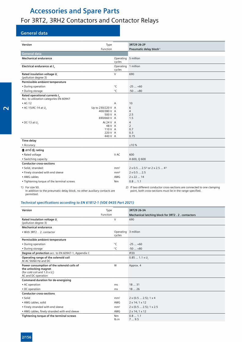
General data General data
Version Type 3RT29 26-2P
Function Pneumatic delay block1)
General dataMechanical endurance Operating
cycles5 million
Electrical endurance at Ie Operating cycles
1 million
Rated insulation voltage Ui (pollution degree 3)
V 690
Permissible ambient temperature
• During operation °C -25 ... +60
• During storage °C -50 ... +80
Rated operational currents Ie
Acc. to utilization categories EN 60947
• AC-12 A 10
• AC-15/AC-14 at Ue Up to 230/220 V400/380 V
500 V690/660 V
AAAA
642.51.5
• DC-13 at Ue At 24 V48 V
110 V220 V440 V
AAAAA
420.70.30.15
Time delay
• Accuracy ±10 %
and rating
• Rated voltage V AC 600
• Switching capacity A 600, Q 600
Conductor cross-sections
• Solid, stranded: mm2 2 x 0.5 ... 2.52) or 2 x 2.5 ... 42)
• Finely stranded with end sleeve mm² 2 x 0.5 ... 2.5
• AWG cables AWG 2 x 22 ... 14
• Tightening torque of the terminal screws Nm 0.8 ... 1.1
1) For size S0. In addition to the pneumatic delay block, no other auxiliary contacts are permitted.
2) If two different conductor cross-sections are connected to one clamping point, both cross-sections must lie in the range specified.
Technical specifications according to EN 61812-1 (VDE 0435 Part 2021)
Version Type 3RT29 26-3A
Function Mechanical latching block for 3RT2 . 2 . contactors
Rated insulation voltage Ui
(pollution degree 3)V 690
Mechanical endurance
• With 3RT2 . 2. contactor Operating cycles
3 million
Permissible ambient temperature
• During operation °C -25 ... +60
• During storage °C -50 ... +80
Degree of protection acc. to EN 60947-1, Appendix C IP20
Operating range of the solenoid coil At AC 50/60 Hz and DC
0.85 ... 1.1 x Us
Power consumption of the solenoid coils of the unlocking magnet (for cold coil and 1.0 x Us) AC and DC operation
W Approx. 4
Command duration for de-energizing
• AC operation ms 18 ... 31
• DC operation ms 18 ... 26
Conductor cross-sections
• Solid mm2 2 x (0.5 ... 2.5); 1 x 4
• AWG cables, solid AWG 2 x 14; 1 x 12
• Finely stranded with end sleeve mm2 2 x (0.5 ... 2.5); 1 x 2.5
• AWG cables, finely stranded with end sleeve AWG 2 x 14; 1 x 12
Tightening torque of the terminal screws Nmlb.in
0.8 ... 1.17 ... 9.5
Accessories and Spare PartsFor 3RT2, 3RH2 Contactors and Contactor Relays
2/156
2
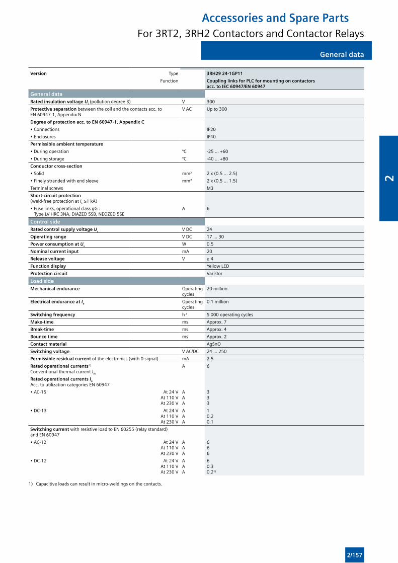
General dataGeneral data
Version Type 3RH29 24-1GP11
Function Coupling links for PLC for mounting on contactors acc. to IEC 60947/EN 60947
General dataRated insulation voltage Ui (pollution degree 3) V 300
Protective separation between the coil and the contacts acc. to EN 60947-1, Appendix N
V AC Up to 300
Degree of protection acc. to EN 60947-1, Appendix C
• Connections IP20
• Enclosures IP40
Permissible ambient temperature
• During operation °C -25 ... +60
• During storage °C -40 ... +80
Conductor cross-section
• Solid mm2 2 x (0.5 ... 2.5)
• Finely stranded with end sleeve mm² 2 x (0.5 ... 1.5)
Terminal screws M3
Short-circuit protection (weld-free protection at Ik ≥1 kA)
• Fuse links, operational class gG : Type LV HRC 3NA, DIAZED 5SB, NEOZED 5SE
A 6
Control sideRated control supply voltage Us V DC 24
Operating range V DC 17 ... 30
Power consumption at Us W 0.5
Nominal current input mA 20
Release voltage V ≥ 4
Function display Yellow LED
Protection circuit Varistor
Load sideMechanical endurance Operating
cycles20 million
Electrical endurance at Ie Operating cycles
0.1 million
Switching frequency h-1 5 000 operating cycles
Make-time ms Approx. 7
Break-time ms Approx. 4
Bounce time ms Approx. 2
Contact material AgSnO
Switching voltage V AC/DC 24 ... 250
Permissible residual current of the electronics (with 0 signal) mA 2.5
Rated operational currents1) Conventional thermal current Ith
A 6
Rated operational currents Ie
Acc. to utilization categories EN 60947
• AC-15 At 24 VAt 110 VAt 230 V
AAA
333
• DC-13 At 24 VAt 110 VAt 230 V
AAA
10.20.1
Switching current with resistive load to EN 60255 (relay standard) and EN 60947
• AC-12 At 24 VAt 110 VAt 230 V
AAA
666
• DC-12 At 24 VAt 110 VAt 230 V
AAA
60.30.21)
1) Capacitive loads can result in micro-weldings on the contacts.
Accessories and Spare PartsFor 3RT2, 3RH2 Contactors and Contactor Relays
2/157
2
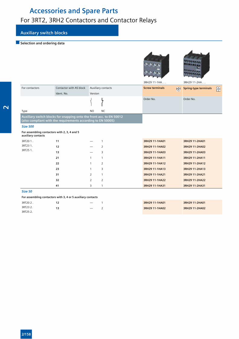
Auxiliary switch blocks Auxiliary switch blocks
Selection and ordering data
3RH29 11-1HA . . 3RH29 11-2HA . .
For contactors Contactor with AS block Auxiliary contacts Screw terminals Spring-type terminals
Ident. No. Version
Order No. Order No.
Type NO NC
Auxiliary switch blocks for snapping onto the front acc. to EN 50012 (also compliant with the requirements according to EN 50005)
Size S00
For assembling contactors with 2, 3, 4 and 5 auxiliary contacts
3RT20 1 .
3RT23 1.
3RT25 1.
11 — 1 3RH29 11-1HA01 3RH29 11-2HA01
12 — 2 3RH29 11-1HA02 3RH29 11-2HA02
13 — 3 3RH29 11-1HA03 3RH29 11-2HA03
21 1 1 3RH29 11-1HA11 3RH29 11-2HA11
22 1 2 3RH29 11-1HA12 3RH29 11-2HA12
23 1 3 3RH29 11-1HA13 3RH29 11-2HA13
31 2 1 3RH29 11-1HA21 3RH29 11-2HA21
32 2 2 3RH29 11-1HA22 3RH29 11-2HA22
41 3 1 3RH29 11-1HA31 3RH29 11-2HA31
Size S0
For assembling contactors with 3, 4 or 5 auxiliary contacts
3RT20 2 .
3RT23 2.
3RT25 2.
12 — 1 3RH29 11-1HA01 3RH29 11-2HA01
13 — 2 3RH29 11-1HA02 3RH29 11-2HA02
Accessories and Spare PartsFor 3RT2, 3RH2 Contactors and Contactor Relays
2/158
2
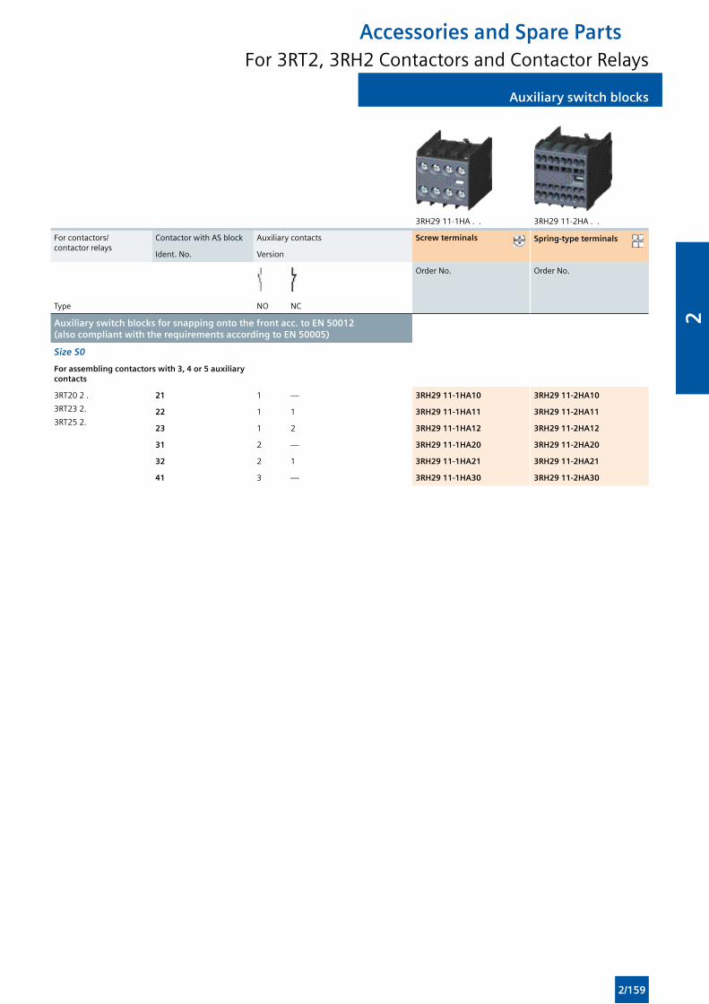
Auxiliary switch blocksAuxiliary switch blocks
3RH29 11-1HA . . 3RH29 11-2HA . .
For contactors/ contactor relays
Contactor with AS block Auxiliary contacts Screw terminals Spring-type terminals
Ident. No. Version
Order No. Order No.
Type NO NC
Auxiliary switch blocks for snapping onto the front acc. to EN 50012 (also compliant with the requirements according to EN 50005)
Size S0
For assembling contactors with 3, 4 or 5 auxiliary contacts
3RT20 2 .
3RT23 2.
3RT25 2.
21 1 — 3RH29 11-1HA10 3RH29 11-2HA10
22 1 1 3RH29 11-1HA11 3RH29 11-2HA11
23 1 2 3RH29 11-1HA12 3RH29 11-2HA12
31 2 — 3RH29 11-1HA20 3RH29 11-2HA20
32 2 1 3RH29 11-1HA21 3RH29 11-2HA21
41 3 — 3RH29 11-1HA30 3RH29 11-2HA30
Accessories and Spare PartsFor 3RT2, 3RH2 Contactors and Contactor Relays
2/159
2
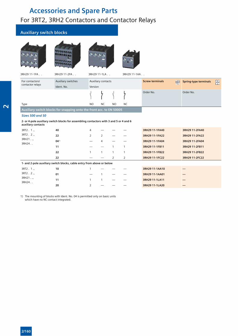
Auxiliary switch blocks Auxiliary switch blocks
3RH29 11-1FA . . 3RH29 11-2FA . . 3RH29 11-1LA . . 3RH29 11-1AA . .
For contactors/ contactor relays
Auxiliary switches Auxiliary contacts Screw terminals Spring-type terminals
Ident. No. Version
Order No. Order No.
Type NO NC NO NC
Auxiliary switch blocks for snapping onto the front acc. to EN 50005
Sizes S00 and S0
2- or 4-pole auxiliary switch blocks for assembling contactors with 3 and 5 or 4 and 6 auxiliary contacts
3RT2 . 1 .,
3RT2 . 2 .,
3RH21 . .,
3RH24 . .
40 4 — — — 3RH29 11-1FA40 3RH29 11-2FA40
22 2 2 — — 3RH29 11-1FA22 3RH29 11-2FA22
041) — 4 — — 3RH29 11-1FA04 3RH29 11-2FA04
11 — — 1 1 3RH29 11-1FB11 3RH29 11-2FB11
22 1 1 1 1 3RH29 11-1FB22 3RH29 11-2FB22
22 — — 2 2 3RH29 11-1FC22 3RH29 11-2FC22
1- and 2-pole auxiliary switch blocks, cable entry from above or below
3RT2 . 1 .,
3RT2 . 2 .,
3RH21 . .,
3RH24 . .
10 1 — — — 3RH29 11-1AA10 —
01 — 1 — — 3RH29 11-1AA01 —
11 1 1 — — 3RH29 11-1LA11 —
20 2 — — — 3RH29 11-1LA20 —
1) The mounting of blocks with Ident. No. 04 is permitted only on basic units which have no NC contact integrated.
Accessories and Spare PartsFor 3RT2, 3RH2 Contactors and Contactor Relays
2/160
2
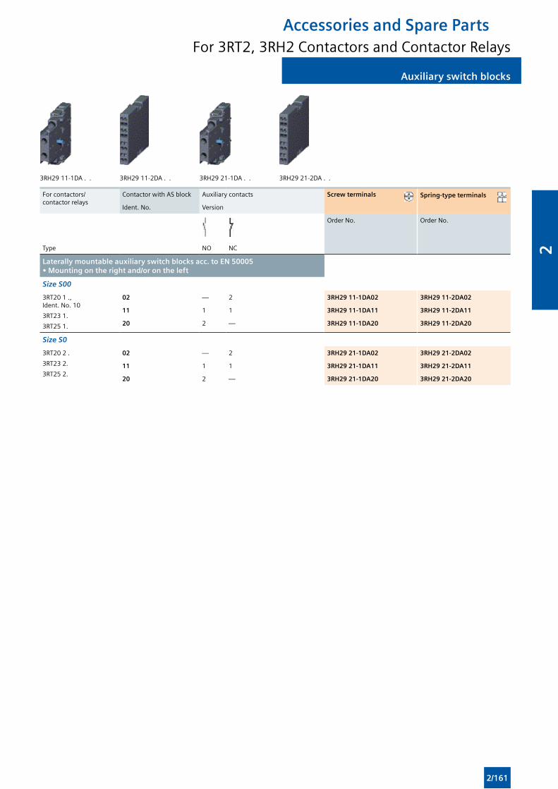
Auxiliary switch blocksAuxiliary switch blocks
3RH29 11-1DA . . 3RH29 11-2DA . . 3RH29 21-1DA . . 3RH29 21-2DA . .
For contactors/ contactor relays
Contactor with AS block Auxiliary contacts Screw terminals Spring-type terminals
Ident. No. Version
Order No. Order No.
Type NO NC
Laterally mountable auxiliary switch blocks acc. to EN 50005 • Mounting on the right and/or on the left
Size S00
3RT20 1 ., Ident. No. 10
3RT23 1.
3RT25 1.
02 — 2 3RH29 11-1DA02 3RH29 11-2DA02
11 1 1 3RH29 11-1DA11 3RH29 11-2DA11
20 2 — 3RH29 11-1DA20 3RH29 11-2DA20
Size S0
3RT20 2 .
3RT23 2.
3RT25 2.
02 — 2 3RH29 21-1DA02 3RH29 21-2DA02
11 1 1 3RH29 21-1DA11 3RH29 21-2DA11
20 2 — 3RH29 21-1DA20 3RH29 21-2DA20
Accessories and Spare PartsFor 3RT2, 3RH2 Contactors and Contactor Relays
2/161
2
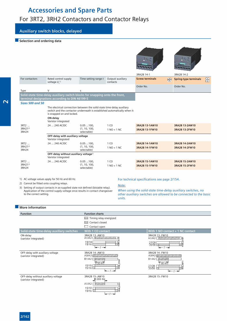
Auxiliary switch blocks, delayed Auxiliary switch blocks, delayed
Selection and ordering data
3RA28 14-1 3RA28 14-2
For contactors Rated control supply voltage Us
1)
Time setting range t Output/ auxiliary contacts
Screw terminals Spring-type terminals
Order No. Order No.
Type V s
Solid-state time-delay auxiliary switch blocks for snapping onto the front, terminal designations according to DIN 46199-5
Sizes S00 and S0The electrical connection between the solid-state time-delay auxiliary switch and the contactor underneath is established automatically when it is snapped on and locked.
ON-delay Varistor integrated
3RT2 . , 3RH212)
3RH24
24 ... 240 AC/DC 0.05 ...100, (1, 10, 100, selectable)
1 CO 3RA28 13-1AW10 3RA28 13-2AW10
1 NO + 1 NC 3RA28 13-1FW10 3RA28 13-2FW10
OFF-delay with auxiliary voltage Varistor integrated
3RT2 . , 3RH212)
3RH24
24 ... 240 AC/DC 0.05 ...100, (1, 10, 100, selectable)
1 CO 3RA28 14-1AW10 3RA28 14-2AW10
1 NO + 1 NC 3RA28 14-1FW10 3RA28 14-2FW10
OFF-delay without auxiliary voltage3)
Varistor integrated
3RT2 . , 3RH212)
3RH24
24 ... 240 AC/DC 0.05 ...100, (1, 10, 100, selectable)
1 CO 3RA28 15-1AW10 3RA28 15-2AW10
1 NO + 1 NC 3RA28 15-1FW10 3RA28 15-2FW10
1) AC voltage values apply for 50 Hz and 60 Hz.
2) Cannot be fitted onto coupling relays.
3) Setting of output contacts in as-supplied state not defined (bistable relay). Application of the control supply voltage once results in contact changeover to the correct setting.
For technical specifications see page 2/154.
Note:
When using the solid-state time-delay auxiliary switches, no other auxiliary switches are allowed to be connected to the basic units.
More information
Function Function charts
Timing relay energized
Contact closed
Contact open
Solid-state time-delay auxiliary switches With 1 CO contact With 1 NO contact + 1 NC contactON-delay (varistor integrated)
3RA28 13-.AW10 3RA28 13-.FW10
OFF-delay with auxiliary voltage (varistor integrated)
3RA28 14-.AW10 3RA28 14-.FW10
OFF-delay without auxiliary voltage (varistor integrated)
3RA28 15-.AW10 3RA28 15-.FW10
Accessories and Spare PartsFor 3RT2, 3RH2 Contactors and Contactor Relays
2/162
2
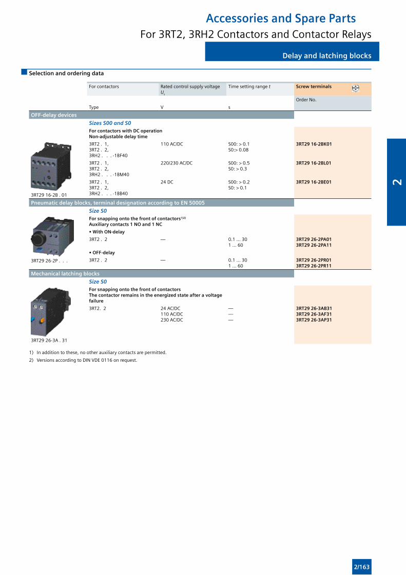
Delay and latching blocksDelay and latching blocks
Selection and ordering data
For contactors Rated control supply voltage Us
Time setting range t Screw terminals
Order No.
Type V s
OFF-delay devices
Sizes S00 and S0For contactors with DC operationNon-adjustable delay time
3RT29 16-2B . 01
3RT2 . 1, 3RT2 . 2, 3RH2 . . . -1BF40
110 AC/DC S00: > 0.1S0:> 0.08
3RT29 16-2BK01
3RT2 . 1, 3RT2 . 2, 3RH2 . . . -1BM40
220/230 AC/DC S00: > 0.5S0: > 0.3
3RT29 16-2BL01
3RT2 . 1, 3RT2 . 2, 3RH2 . . . -1BB40
24 DC S00: > 0.2S0: > 0.1
3RT29 16-2BE01
Pneumatic delay blocks, terminal designation according to EN 50005
Size S0
3RT29 26-2P . . .
For snapping onto the front of contactors1)2)
Auxiliary contacts 1 NO and 1 NC
• With ON-delay
3RT2 . 2 — 0.1 ... 301 ... 60
3RT29 26-2PA013RT29 26-2PA11
• OFF-delay
3RT2 . 2 — 0.1 ... 301 ... 60
3RT29 26-2PR013RT29 26-2PR11
Mechanical latching blocks
Size S0
3RT29 26-3A . 31
For snapping onto the front of contactorsThe contactor remains in the energized state after a voltage failure
3RT2. 2 24 AC/DC110 AC/DC230 AC/DC
———
3RT29 26-3AB313RT29 26-3AF313RT29 26-3AP31
1) In addition to these, no other auxiliary contacts are permitted.
2) Versions according to DIN VDE 0116 on request.
Accessories and Spare PartsFor 3RT2, 3RH2 Contactors and Contactor Relays
2/163
2
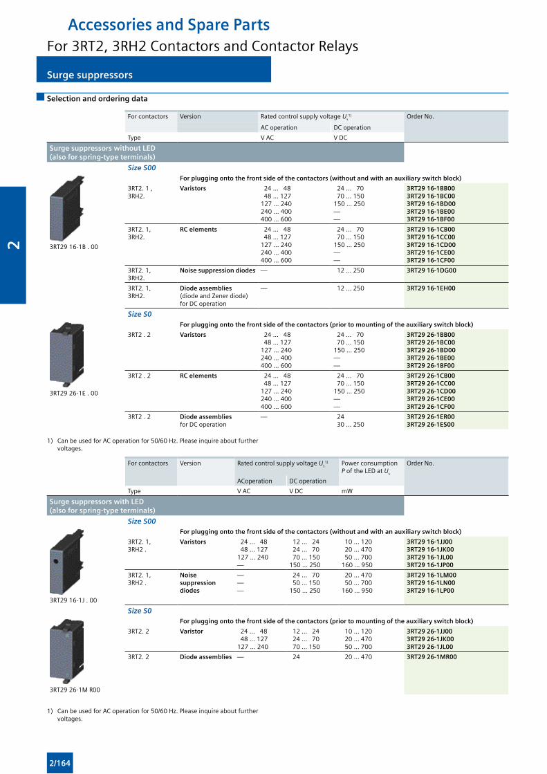
Surge suppressors Surge suppressors
Selection and ordering data
For contactors Version Rated control supply voltage Us1) Order No.
AC operation DC operation
Type V AC V DC
Surge suppressors without LED (also for spring-type terminals)
Size S00
3RT29 16-1B . 00
For plugging onto the front side of the contactors (without and with an auxiliary switch block)
3RT2. 1 , 3RH2.
Varistors 24 ... 48 48 ... 127127 ... 240240 ... 400400 ... 600
24 ... 70 70 ... 150150 ... 250——
3RT29 16-1BB003RT29 16-1BC003RT29 16-1BD003RT29 16-1BE003RT29 16-1BF00
3RT2. 1, 3RH2.
RC elements 24 ... 48 48 ... 127127 ... 240240 ... 400400 ... 600
24 ... 70 70 ... 150150 ... 250——
3RT29 16-1CB003RT29 16-1CC003RT29 16-1CD003RT29 16-1CE003RT29 16-1CF00
3RT2. 1, 3RH2.
Noise suppression diodes — 12 ... 250 3RT29 16-1DG00
3RT2. 1, 3RH2.
Diode assemblies (diode and Zener diode) for DC operation
— 12 ... 250 3RT29 16-1EH00
Size S0
3RT29 26-1E . 00
For plugging onto the front side of the contactors (prior to mounting of the auxiliary switch block)
3RT2 . 2 Varistors 24 ... 48 48 ... 127127 ... 240240 ... 400400 ... 600
24 ... 70 70 ... 150150 ... 250——
3RT29 26-1BB003RT29 26-1BC003RT29 26-1BD003RT29 26-1BE003RT29 26-1BF00
3RT2 . 2 RC elements 24 ... 48 48 ... 127127 ... 240240 ... 400400 ... 600
24 ... 70 70 ... 150150 ... 250——
3RT29 26-1CB003RT29 26-1CC003RT29 26-1CD003RT29 26-1CE003RT29 26-1CF00
3RT2 . 2 Diode assemblies for DC operation
— 24 30 ... 250
3RT29 26-1ER003RT29 26-1ES00
1) Can be used for AC operation for 50/60 Hz. Please inquire about further voltages.
For contactors Version Rated control supply voltage Us1) Power consumption
P of the LED at Us
Order No.
ACoperation DC operation
Type V AC V DC mW
Surge suppressors with LED (also for spring-type terminals)
Size S00
3RT29 16-1J . 00
For plugging onto the front side of the contactors (without and with an auxiliary switch block)
3RT2. 1, 3RH2 .
Varistors 24 ... 48 48 ... 127127 ... 240—
12 ... 24 24 ... 70 70 ... 150150 ... 250
10 ... 120 20 ... 470 50 ... 700160 ... 950
3RT29 16-1JJ003RT29 16-1JK003RT29 16-1JL003RT29 16-1JP00
3RT2. 1, 3RH2 .
Noise suppression diodes
———
24 ... 70 50 ... 150150 ... 250
20 ... 470 50 ... 700160 ... 950
3RT29 16-1LM003RT29 16-1LN003RT29 16-1LP00
Size S0
3RT29 26-1M R00
For plugging onto the front side of the contactors (prior to mounting of the auxiliary switch block)
3RT2. 2 Varistor 24 ... 48 48 ... 127127 ... 240
12 ... 24 24 ... 70 70 ... 150
10 ... 120 20 ... 470 50 ... 700
3RT29 26-1JJ003RT29 26-1JK003RT29 26-1JL00
3RT2. 2 Diode assemblies — 24 20 ... 470 3RT29 26-1MR00
1) Can be used for AC operation for 50/60 Hz. Please inquire about further voltages.
Accessories and Spare PartsFor 3RT2, 3RH2 Contactors and Contactor Relays
2/164
2
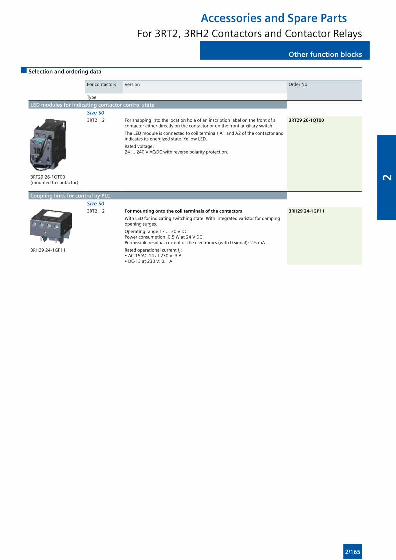
Other function blocksOther function blocks
Selection and ordering data
For contactors Version Order No.
Type
LED modules for indicating contactor control state
Size S0
3RT29 26-1QT00 (mounted to contactor)
3RT2 . 2 For snapping into the location hole of an inscription label on the front of a contactor either directly on the contactor or on the front auxiliary switch.
The LED module is connected to coil terminals A1 and A2 of the contactor and indicates its energized state. Yellow LED.
Rated voltage: 24 ... 240 V AC/DC with reverse polarity protection.
3RT29 26-1QT00
Coupling links for control by PLC
Size S0
3RH29 24-1GP11
3RT2 . 2 For mounting onto the coil terminals of the contactors 3RH29 24-1GP11
With LED for indicating switching state. With integrated varistor for damping opening surges.
Operating range 17 ... 30 V DC Power consumption: 0.5 W at 24 V DC Permissible residual current of the electronics (with 0 signal): 2.5 mA
Rated operational current Ie: • AC-15/AC-14 at 230 V: 3 A • DC-13 at 230 V: 0.1 A
Accessories and Spare PartsFor 3RT2, 3RH2 Contactors and Contactor Relays
2/165
2
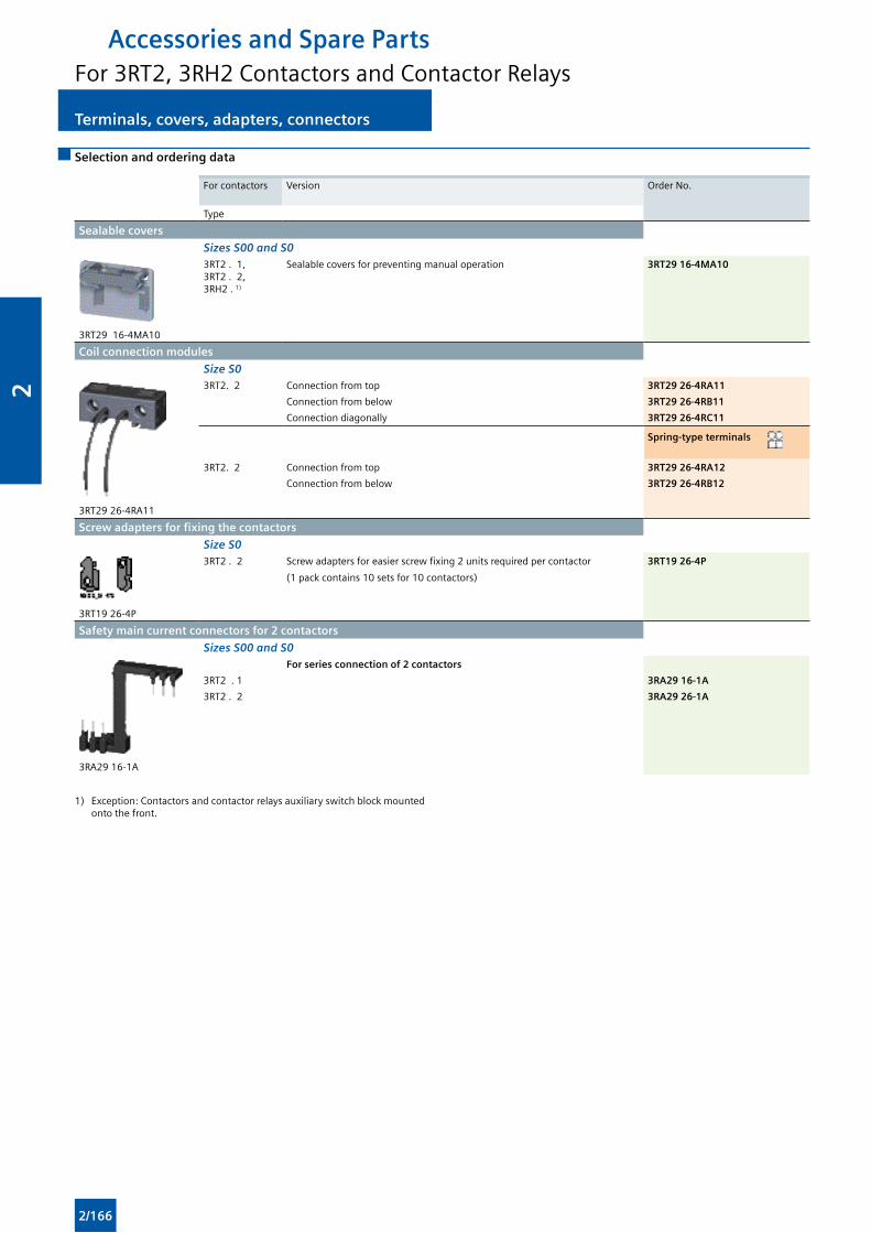
Terminals, covers, adapters, connectors Terminals, covers, adapters, connectors
Selection and ordering data
For contactors Version Order No.
Type
Sealable covers
Sizes S00 and S0
3RT29 16-4MA10
3RT2 . 1, 3RT2 . 2, 3RH2 . 1)
Sealable covers for preventing manual operation 3RT29 16-4MA10
Coil connection modules
Size S0
3RT29 26-4RA11
3RT2. 2 Connection from top 3RT29 26-4RA11
Connection from below 3RT29 26-4RB11
Connection diagonally 3RT29 26-4RC11
Spring-type terminals
3RT2. 2 Connection from top 3RT29 26-4RA12
Connection from below 3RT29 26-4RB12
Screw adapters for fixing the contactors
Size S0
3RT19 26-4P
3RT2 . 2 Screw adapters for easier screw fixing 2 units required per contactor
(1 pack contains 10 sets for 10 contactors)
3RT19 26-4P
Safety main current connectors for 2 contactors
Sizes S00 and S0
3RA29 16-1A
For series connection of 2 contactors
3RT2 . 1 3RA29 16-1A
3RT2 . 2 3RA29 26-1A
1) Exception: Contactors and contactor relays auxiliary switch block mounted onto the front.
Accessories and Spare PartsFor 3RT2, 3RH2 Contactors and Contactor Relays
2/166
2
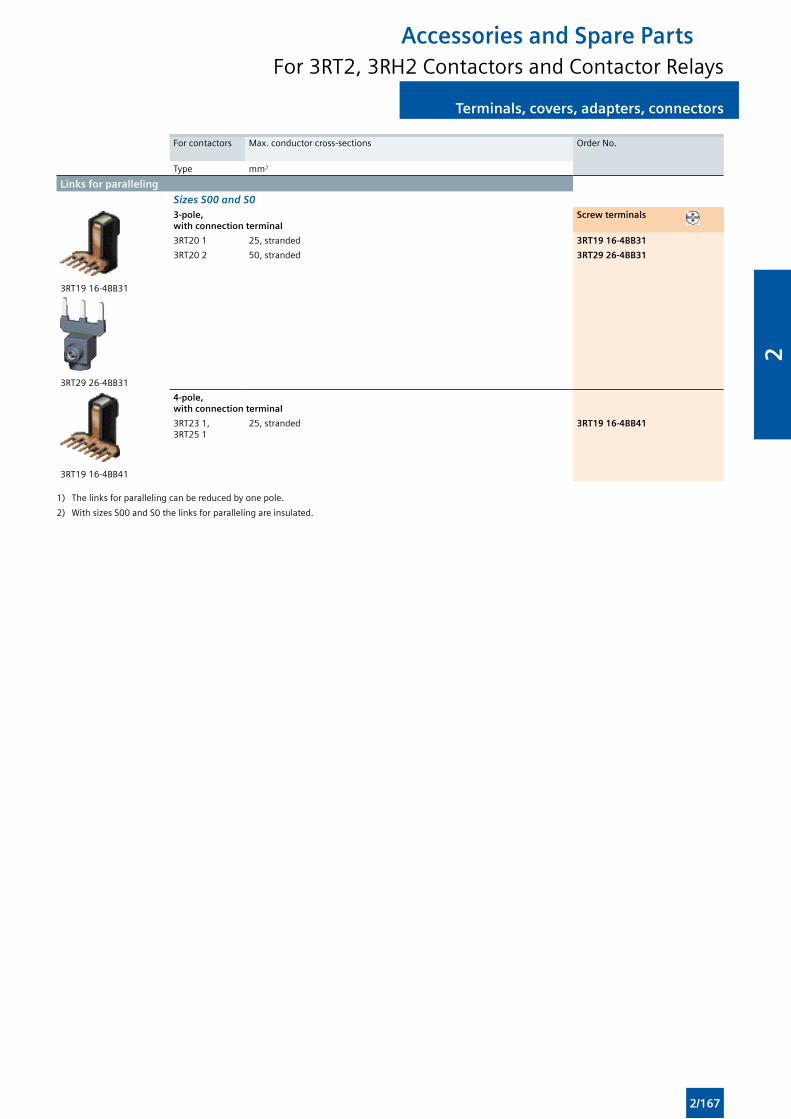
Terminals, covers, adapters, connectorsTerminals, covers, adapters, connectors
For contactors Max. conductor cross-sections Order No.
Type mm2
Links for paralleling
Sizes S00 and S0
3RT19 16-4BB31
3RT29 26-4BB31
3-pole, with connection terminal
Screw terminals
3RT20 1 25, stranded 3RT19 16-4BB31
3RT20 2 50, stranded 3RT29 26-4BB31
3RT19 16-4BB41
4-pole, with connection terminal
3RT23 1, 3RT25 1
25, stranded 3RT19 16-4BB41
1) The links for paralleling can be reduced by one pole.
2) With sizes S00 and S0 the links for paralleling are insulated.
Accessories and Spare PartsFor 3RT2, 3RH2 Contactors and Contactor Relays
2/167
2
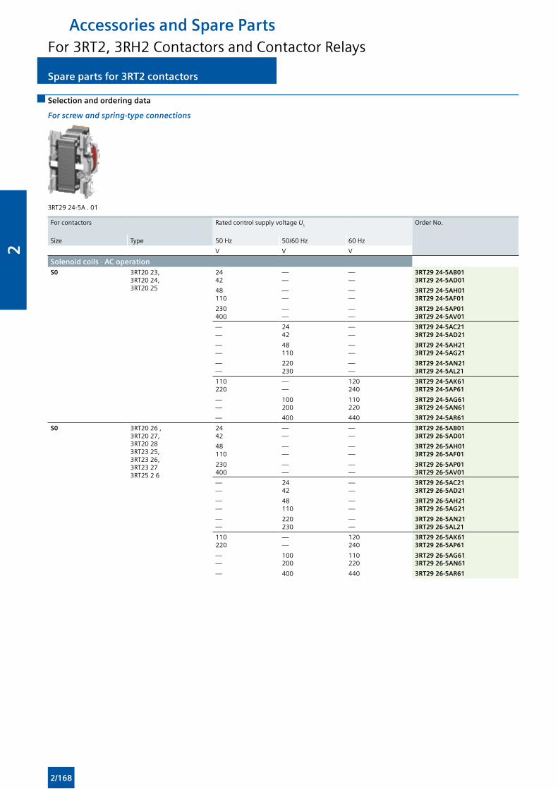
Spare parts for 3RT2 contactors Spare parts for 3RT2 contactors
Selection and ordering data
For screw and spring-type connections
3RT29 24-5A . 01
For contactors Rated control supply voltage Us Order No.
Size Type 50 Hz 50/60 Hz 60 Hz
V V V
Solenoid coils · AC operation S0 3RT20 23,
3RT20 24, 3RT20 25
2442
——
——
3RT29 24-5AB013RT29 24-5AD01
48110
——
——
3RT29 24-5AH013RT29 24-5AF01
230400
——
——
3RT29 24-5AP013RT29 24-5AV01
——
2442
——
3RT29 24-5AC213RT29 24-5AD21
——
48110
——
3RT29 24-5AH213RT29 24-5AG21
——
220230
——
3RT29 24-5AN213RT29 24-5AL21
110220
——
120240
3RT29 24-5AK613RT29 24-5AP61
——
100200
110220
3RT29 24-5AG613RT29 24-5AN61
— 400 440 3RT29 24-5AR61
S0 3RT20 26 , 3RT20 27, 3RT20 28 3RT23 25, 3RT23 26, 3RT23 273RT25 2 6
2442
——
——
3RT29 26-5AB013RT29 26-5AD01
48110
——
——
3RT29 26-5AH013RT29 26-5AF01
230400
——
——
3RT29 26-5AP013RT29 26-5AV01
——
2442
——
3RT29 26-5AC213RT29 26-5AD21
——
48110
——
3RT29 26-5AH213RT29 26-5AG21
——
220230
——
3RT29 26-5AN213RT29 26-5AL21
110220
——
120240
3RT29 26-5AK613RT29 26-5AP61
——
100200
110220
3RT29 26-5AG613RT29 26-5AN61
— 400 440 3RT29 26-5AR61
Accessories and Spare PartsFor 3RT2, 3RH2 Contactors and Contactor Relays
2/168
2
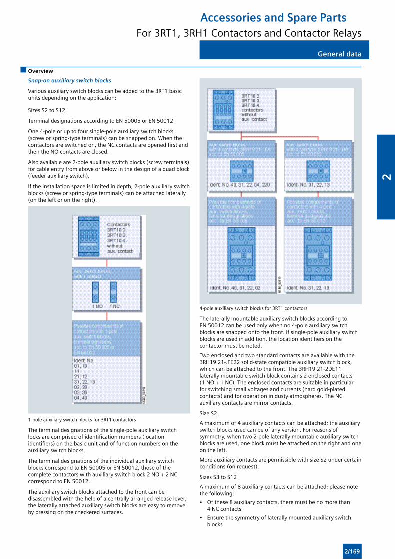
General dataGeneral data
Overview
Snap-on auxiliary switch blocks
Various auxiliary switch blocks can be added to the 3RT1 basic units depending on the application:
Sizes S2 to S12
Terminal designations according to EN 50005 or EN 50012
One 4-pole or up to four single-pole auxiliary switch blocks (screw or spring-type terminals) can be snapped on. When the contactors are switched on, the NC contacts are opened first and then the NO contacts are closed.
Also available are 2-pole auxiliary switch blocks (screw terminals) for cable entry from above or below in the design of a quad block (feeder auxiliary switch).
If the installation space is limited in depth, 2-pole auxiliary switch blocks (screw or spring-type terminals) can be attached laterally (on the left or on the right).
1-pole auxiliary switch blocks for 3RT1 contactors
The terminal designations of the single-pole auxiliary switch locks are comprised of identification numbers (location identifiers) on the basic unit and of function numbers on the auxiliary switch blocks.
The terminal designations of the individual auxiliary switch blocks correspond to EN 50005 or EN 50012, those of the complete contactors with auxiliary switch block 2 NO + 2 NC correspond to EN 50012.
The auxiliary switch blocks attached to the front can be disassembled with the help of a centrally arranged release lever; the laterally attached auxiliary switch blocks are easy to remove by pressing on the checkered surfaces.
4-pole auxiliary switch blocks for 3RT1 contactors
The laterally mountable auxiliary switch blocks according to EN 50012 can be used only when no 4-pole auxiliary switch blocks are snapped onto the front. If single-pole auxiliary switch blocks are used in addition, the location identifiers on the contactor must be noted.
Two enclosed and two standard contacts are available with the 3RH19 21-.FE22 solid-state compatible auxiliary switch block, which can be attached to the front. The 3RH19 21-2DE11 laterally mountable switch block contains 2 enclosed contacts (1 NO + 1 NC). The enclosed contacts are suitable in particular for switching small voltages and currents (hard gold-plated contacts) and for operation in dusty atmospheres. The NC auxiliary contacts are mirror contacts.
Size S2
A maximum of 4 auxiliary contacts can be attached; the auxiliary switch blocks used can be of any version. For reasons of symmetry, when two 2-pole laterally mountable auxiliary switch blocks are used, one block must be attached on the right and one on the left.
More auxiliary contacts are permissible with size S2 under certain conditions (on request).
Sizes S3 to S12
A maximum of 8 auxiliary contacts can be attached; please note the following:
• Of these 8 auxiliary contacts, there must be no more than 4 NC contacts
• Ensure the symmetry of laterally mounted auxiliary switch blocks
Accessories and Spare PartsFor 3RT1, 3RH1 Contactors and Contactor Relays
2/169
2
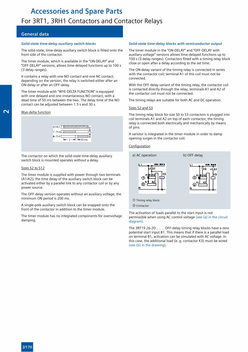
General data General data
Solid-state time-delay auxiliary switch blocks
The solid-state, time-delay auxiliary switch block is fitted onto the front side of the contactor.
The timer module, which is available in the “ON-DELAY” and “OFF-DELAY” versions, allows time-delayed functions up to 100 s (3 delay ranges).
It contains a relay with one NO contact and one NC contact; depending on the version, the relay is switched either after an ON-delay or after an OFF-delay.
The timer module with “WYE-DELTA FUNCTION” is equipped with one delayed and one instantaneous NO contact, with a dead time of 50 ms between the two. The delay time of the NO contact can be adjusted between 1.5 s and 30 s.
Wye-delta function
The contactor on which the solid-state time-delay auxiliary switch block is mounted operates without a delay.
Sizes S2 to S12
The timer module is supplied with power through two terminals (A1/A2); the time delay of the auxiliary switch block can be activated either by a parallel link to any contactor coil or by any power source.
The OFF-delay version operates without an auxiliary voltage; the minimum ON period is 200 ms.
A single-pole auxiliary switch block can be snapped onto the front of the contactor in addition to the timer module.
The timer module has no integrated components for overvoltage damping.
Solid-state time-delay blocks with semiconductor output
The timer module in the “ON-DELAY” and “OFF-DELAY with auxiliary voltage” versions allows time-delayed functions up to 100 s (3 delay ranges). Contactors fitted with a timing relay block close or open after a delay according to the set time.
The ON-delay variant of the timing relay is connected in series with the contactor coil; terminal A1 of this coil must not be connected.
With the OFF-delay variant of the timing relay, the contactor coil is contacted directly through the relay; terminals A1 and A2 of the contactor coil must not be connected.
The timing relays are suitable for both AC and DC operation.
Sizes S2 and S3
The timing relay block for size S0 to S3 contactors is plugged into coil terminals A1 and A2 on top of each contactor; the timing relay is connected both electrically and mechanically by means of pins.
A varistor is integrated in the timer module in order to damp opening surges in the contactor coil.
Configuration
a) AC operation b) OFF-delay
Timing relay block
Contactor
The activation of loads parallel to the start input is not permissible when using AC control voltage (see (a) in the circuit diagram).
The 3RT19 26-2D . . . OFF-delay timing relay blocks have a zero potential start input B1. This means that if there is a parallel load on terminal B1, activation can be simulated with AC voltage. In this case, the additional load (e. g. contactor K3) must be wired (see (b) in the drawing).
Accessories and Spare PartsFor 3RT1, 3RH1 Contactors and Contactor Relays
2/170
2
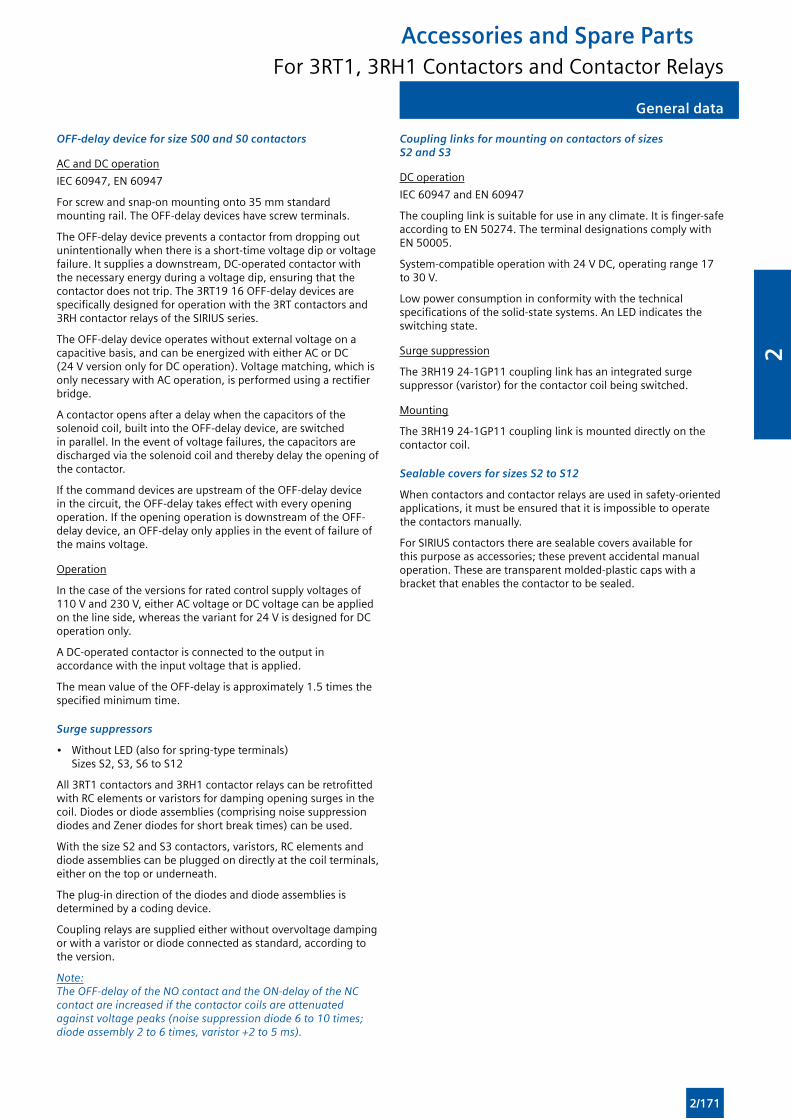
General dataGeneral data
OFF-delay device for size S00 and S0 contactors
AC and DC operation
IEC 60947, EN 60947
For screw and snap-on mounting onto 35 mm standard mounting rail. The OFF-delay devices have screw terminals.
The OFF-delay device prevents a contactor from dropping out unintentionally when there is a short-time voltage dip or voltage failure. It supplies a downstream, DC-operated contactor with the necessary energy during a voltage dip, ensuring that the contactor does not trip. The 3RT19 16 OFF-delay devices are specifically designed for operation with the 3RT contactors and 3RH contactor relays of the SIRIUS series.
The OFF-delay device operates without external voltage on a capacitive basis, and can be energized with either AC or DC (24 V version only for DC operation). Voltage matching, which is only necessary with AC operation, is performed using a rectifier bridge.
A contactor opens after a delay when the capacitors of the solenoid coil, built into the OFF-delay device, are switched in parallel. In the event of voltage failures, the capacitors are discharged via the solenoid coil and thereby delay the opening of the contactor.
If the command devices are upstream of the OFF-delay device in the circuit, the OFF-delay takes effect with every opening operation. If the opening operation is downstream of the OFF-delay device, an OFF-delay only applies in the event of failure of the mains voltage.
Operation
In the case of the versions for rated control supply voltages of 110 V and 230 V, either AC voltage or DC voltage can be applied on the line side, whereas the variant for 24 V is designed for DC operation only.
A DC-operated contactor is connected to the output in accordance with the input voltage that is applied.
The mean value of the OFF-delay is approximately 1.5 times the specified minimum time.
Surge suppressors
• Without LED (also for spring-type terminals) Sizes S2, S3, S6 to S12
All 3RT1 contactors and 3RH1 contactor relays can be retrofitted with RC elements or varistors for damping opening surges in the coil. Diodes or diode assemblies (comprising noise suppression diodes and Zener diodes for short break times) can be used.
With the size S2 and S3 contactors, varistors, RC elements and diode assemblies can be plugged on directly at the coil terminals, either on the top or underneath.
The plug-in direction of the diodes and diode assemblies is determined by a coding device.
Coupling relays are supplied either without overvoltage damping or with a varistor or diode connected as standard, according to the version.
Note: The OFF-delay of the NO contact and the ON-delay of the NC contact are increased if the contactor coils are attenuated against voltage peaks (noise suppression diode 6 to 10 times; diode assembly 2 to 6 times, varistor +2 to 5 ms).
Coupling links for mounting on contactors of sizes S2 and S3
DC operation
IEC 60947 and EN 60947
The coupling link is suitable for use in any climate. It is finger-safe according to EN 50274. The terminal designations comply with EN 50005.
System-compatible operation with 24 V DC, operating range 17 to 30 V.
Low power consumption in conformity with the technical specifications of the solid-state systems. An LED indicates the switching state.
Surge suppression
The 3RH19 24-1GP11 coupling link has an integrated surge suppressor (varistor) for the contactor coil being switched.
Mounting
The 3RH19 24-1GP11 coupling link is mounted directly on the contactor coil.
Sealable covers for sizes S2 to S12
When contactors and contactor relays are used in safety-oriented applications, it must be ensured that it is impossible to operate the contactors manually.
For SIRIUS contactors there are sealable covers available for this purpose as accessories; these prevent accidental manual operation. These are transparent molded-plastic caps with a bracket that enables the contactor to be sealed.
Accessories and Spare PartsFor 3RT1, 3RH1 Contactors and Contactor Relays
2/171
2
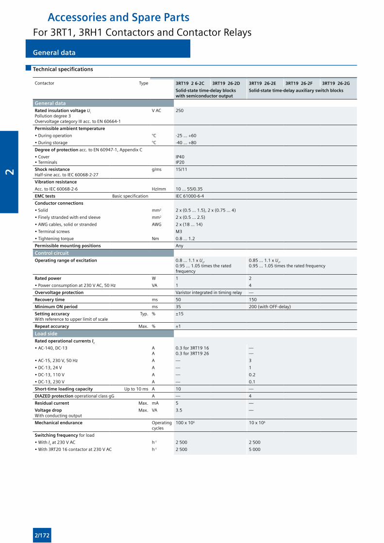
General data General data
Technical specifications
Contactor Type 3RT19 2 6-2C 3RT19 26-2D 3RT19 26-2E 3RT19 26-2F 3RT19 26-2G
Solid-state time-delay blocks with semiconductor output
Solid-state time-delay auxiliary switch blocks
General dataRated insulation voltage Ui Pollution degree 3Overvoltage category III acc. to EN 60664-1
V AC 250
Permissible ambient temperature
• During operation °C -25 ... +60
• During storage °C -40 ... +80
Degree of protection acc. to EN 60947-1, Appendix C
• Cover• Terminals
IP40IP20
Shock resistance Half-sine acc. to IEC 60068-2-27
g/ms 15/11
Vibration resistance
Acc. to IEC 60068-2-6 Hz/mm 10 ... 55/0.35
EMC tests Basic specification IEC 61000-6-4
Conductor connections
• Solid mm2 2 x (0.5 ... 1.5), 2 x (0.75 ... 4)
• Finely stranded with end sleeve mm2 2 x (0.5 ... 2.5)
• AWG cables, solid or stranded AWG 2 x (18 ... 14)
• Terminal screws M3
• Tightening torque Nm 0.8 ... 1.2
Permissible mounting positions Any
Control circuitOperating range of excitation 0.8 ... 1.1 x Us,
0.95 ... 1.05 times the rated frequency
0.85 ... 1.1 x Us, 0.95 ... 1.05 times the rated frequency
Rated power W 1 2
• Power consumption at 230 V AC, 50 Hz VA 1 4
Overvoltage protection Varistor integrated in timing relay —
Recovery time ms 50 150
Minimum ON period ms 35 200 (with OFF-delay)
Setting accuracy With reference to upper limit of scale
Typ. % ±15
Repeat accuracy Max. % ±1
Load sideRated operational currents Ie
• AC-140, DC-13 AA
0.3 for 3RT19 160.3 for 3RT19 26
——
• AC-15, 230 V, 50 Hz A — 3
• DC-13, 24 V A — 1
• DC-13, 110 V A — 0.2
• DC-13, 230 V A — 0.1
Short-time loading capacity Up to 10 ms A 10 —
DIAZED protection operational class gG A — 4
Residual current Max. mA 5 —
Voltage drop With conducting output
Max. VA 3.5 —
Mechanical endurance Operating cycles
100 x 106 10 x 106
Switching frequency for load
• With Ie at 230 V AC h-1 2 500 2 500
• With 3RT20 16 contactor at 230 V AC h-1 2 500 5 000
Accessories and Spare PartsFor 3RT1, 3RH1 Contactors and Contactor Relays
2/172
2
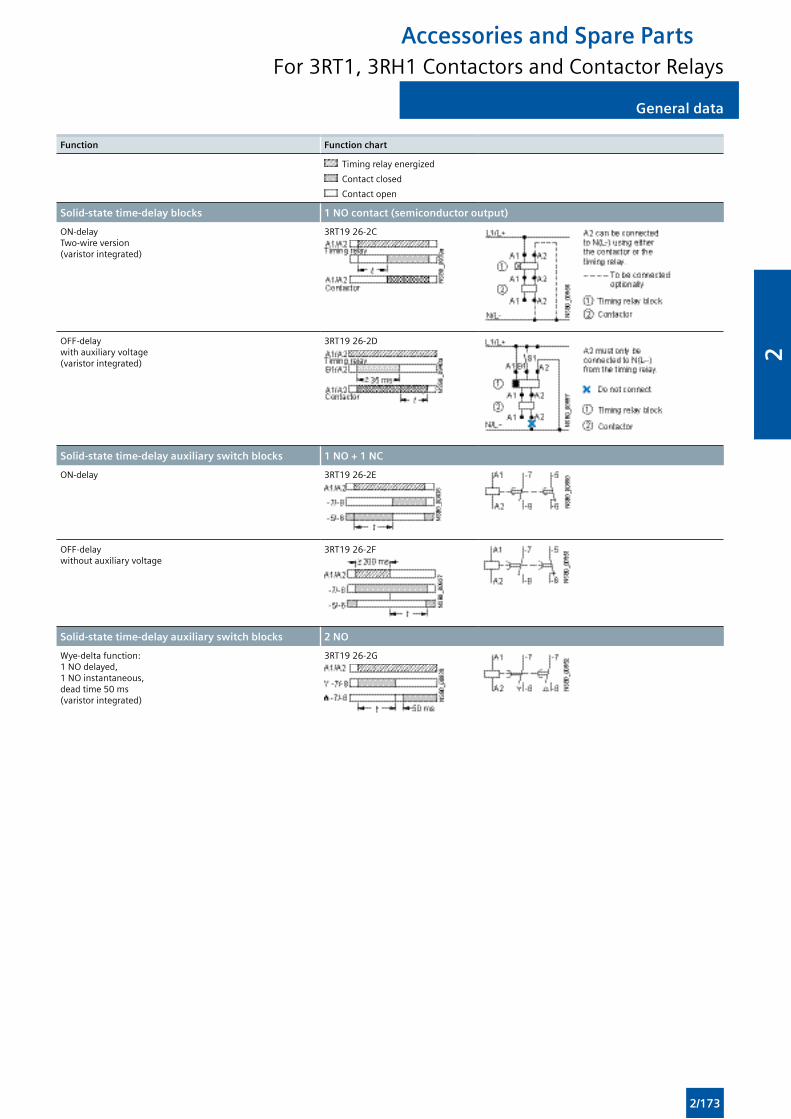
General dataGeneral data
Function Function chart
Timing relay energized
Contact closed
Contact open
Solid-state time-delay blocks 1 NO contact (semiconductor output)
ON-delay Two-wire version (varistor integrated)
3RT19 26-2C
OFF-delay with auxiliary voltage (varistor integrated)
3RT19 26-2D
Solid-state time-delay auxiliary switch blocks 1 NO + 1 NC
ON-delay 3RT19 26-2E
OFF-delay without auxiliary voltage
3RT19 26-2F
Solid-state time-delay auxiliary switch blocks 2 NO
Wye-delta function: 1 NO delayed, 1 NO instantaneous, dead time 50 ms (varistor integrated)
3RT19 26-2G
Accessories and Spare PartsFor 3RT1, 3RH1 Contactors and Contactor Relays
2/173
2
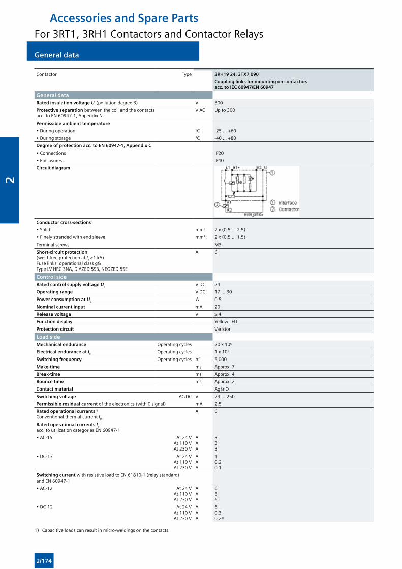
General data General data
Contactor Type 3RH19 24, 3TX7 090
Coupling links for mounting on contactors acc. to IEC 60947/EN 60947
General dataRated insulation voltage Ui (pollution degree 3) V 300
Protective separation between the coil and the contacts acc. to EN 60947-1, Appendix N
V AC Up to 300
Permissible ambient temperature
• During operation °C -25 ... +60
• During storage °C -40 ... +80
Degree of protection acc. to EN 60947-1, Appendix C
• Connections IP20
• Enclosures IP40
Circuit diagram
Conductor cross-sections
• Solid mm2 2 x (0.5 ... 2.5)
• Finely stranded with end sleeve mm² 2 x (0.5 ... 1.5)
Terminal screws M3
Short-circuit protection (weld-free protection at Ik ≥1 kA) Fuse links, operational class gG Type LV HRC 3NA, DIAZED 5SB, NEOZED 5SE
A 6
Control sideRated control supply voltage Us V DC 24
Operating range V DC 17 ... 30
Power consumption at Us W 0.5
Nominal current input mA 20
Release voltage V ≥ 4
Function display Yellow LED
Protection circuit Varistor
Load sideMechanical endurance Operating cycles 20 x 106
Electrical endurance at Ie Operating cycles 1 x 10⁵
Switching frequency Operating cycles h-1 5 000
Make-time ms Approx. 7
Break-time ms Approx. 4
Bounce time ms Approx. 2
Contact material AgSnO
Switching voltage AC/DC V 24 ... 250
Permissible residual current of the electronics (with 0 signal) mA 2.5
Rated operational currents1) Conventional thermal current Ith
A 6
Rated operational currents Ie acc. to utilization categories EN 60947-1
• AC-15 At 24 VAt 110 VAt 230 V
AAA
333
• DC-13 At 24 VAt 110 VAt 230 V
AAA
10.20.1
Switching current with resistive load to EN 61810-1 (relay standard) and EN 60947-1
• AC-12 At 24 VAt 110 VAt 230 V
AAA
666
• DC-12 At 24 VAt 110 VAt 230 V
AAA
60.30.21)
1) Capacitive loads can result in micro-weldings on the contacts.
Accessories and Spare PartsFor 3RT1, 3RH1 Contactors and Contactor Relays
2/174
2
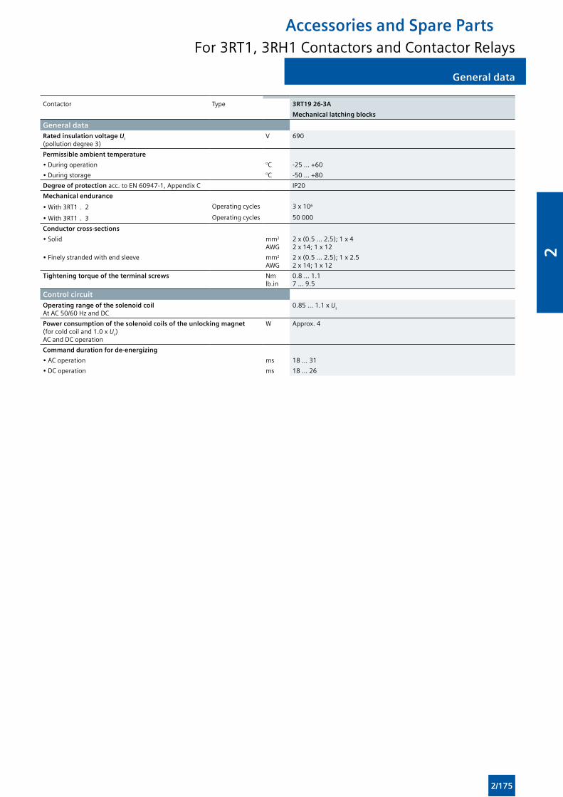
General dataGeneral data
Contactor Type 3RT19 26-3A
Mechanical latching blocks
General dataRated insulation voltage Ui (pollution degree 3)
V 690
Permissible ambient temperature
• During operation °C -25 ... +60
• During storage °C -50 ... +80
Degree of protection acc. to EN 60947-1, Appendix C IP20
Mechanical endurance
• With 3RT1 . 2 Operating cycles 3 x 10⁶
• With 3RT1 . 3 Operating cycles 50 000
Conductor cross-sections
• Solid mm2
AWG2 x (0.5 ... 2.5); 1 x 4 2 x 14; 1 x 12
• Finely stranded with end sleeve mm2
AWG2 x (0.5 ... 2.5); 1 x 2.5 2 x 14; 1 x 12
Tightening torque of the terminal screws Nmlb.in
0.8 ... 1.17 ... 9.5
Control circuitOperating range of the solenoid coil At AC 50/60 Hz and DC
0.85 ... 1.1 x Us
Power consumption of the solenoid coils of the unlocking magnet (for cold coil and 1.0 x Us)AC and DC operation
W Approx. 4
Command duration for de-energizing
• AC operation ms 18 ... 31
• DC operation ms 18 ... 26
Accessories and Spare PartsFor 3RT1, 3RH1 Contactors and Contactor Relays
2/175
2
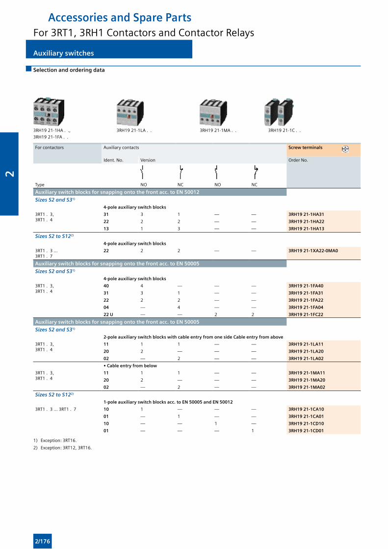
Auxiliary switches Auxiliary switches
Accessories and Spare PartsFor 3RT1, 3RH1 Contactors and Contactor Relays
Selection and ordering data
3RH19 21-1HA . ., 3RH19 21-1LA . . 3RH19 21-1MA . . 3RH19 21-1C . .
3RH19 21-1FA . .
For contactors Auxiliary contacts Screw terminals
Ident. No. Version Order No.
Type NO NC NO NC
Auxiliary switch blocks for snapping onto the front acc. to EN 50012
Sizes S2 and S31)
4-pole auxiliary switch blocks
3RT1 . 3, 3RT1 . 4
31 3 1 — — 3RH19 21-1HA31
22 2 2 — — 3RH19 21-1HA22
13 1 3 — — 3RH19 21-1HA13
Sizes S2 to S122)
4-pole auxiliary switch blocks
3RT1 . 3 ... 3RT1 . 7
22 2 2 — — 3RH19 21-1XA22-0MA0
Auxiliary switch blocks for snapping onto the front acc. to EN 50005
Sizes S2 and S31)
4-pole auxiliary switch blocks
3RT1 . 3, 3RT1 . 4
40 4 — — — 3RH19 21-1FA40
31 3 1 — — 3RH19 21-1FA31
22 2 2 — — 3RH19 21-1FA22
04 — 4 — — 3RH19 21-1FA04
22 U — — 2 2 3RH19 21-1FC22
Auxiliary switch blocks for snapping onto the front acc. to EN 50005
Sizes S2 and S31)
2-pole auxiliary switch blocks with cable entry from one side Cable entry from above
3RT1 . 3, 3RT1 . 4
11 1 1 — — 3RH19 21-1LA11
20 2 — — — 3RH19 21-1LA20
02 — 2 — — 3RH19 21-1LA02
• Cable entry from below
3RT1 . 3, 3RT1 . 4
11 1 1 — — 3RH19 21-1MA11
20 2 — — — 3RH19 21-1MA20
02 — 2 — — 3RH19 21-1MA02
Sizes S2 to S122)
1-pole auxiliary switch blocks acc. to EN 50005 and EN 50012
3RT1 . 3 ... 3RT1 . 7 10 1 — — — 3RH19 21-1CA10
01 — 1 — — 3RH19 21-1CA01
10 — — 1 — 3RH19 21-1CD10
01 — — — 1 3RH19 21-1CD01
1) Exception: 3RT16.
2) Exception: 3RT12, 3RT16.
2/176
2
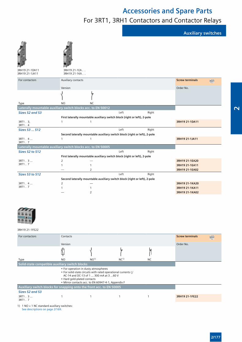
Auxiliary switchesAuxiliary switches
Accessories and Spare PartsFor 3RT1, 3RH1 Contactors and Contactor Relays
3RH19 21-1DA11 3RH19 21-1EA . . 3RH19 21-1JA11 3RH19 21-1KA . .
For contactors Auxiliary contacts Screw terminals
Version Order No.
Type NO NC
Laterally mountable auxiliary switch blocks acc. to EN 50012
Sizes S2 and S3 Left Right
First laterally mountable auxiliary switch block (right or left), 2-pole
3RT1 . 3, 3RT1 . 4
1 1 3RH19 21-1DA11
Sizes S3 ... S12 Left Right
Second laterally mountable auxiliary switch block (right or left), 2-pole
3RT1 . 4 ... 3RT1 . 7
1 1 3RH19 21-1JA11
Laterally mountable auxiliary switch blocks acc. to EN 50005
Sizes S2 to S12 Left Right
First laterally mountable auxiliary switch block (right or left), 2-pole
3RT1 . 3 ... 3RT1 . 7
2 — 3RH19 21-1EA20
1 1 3RH19 21-1EA11
— 2 3RH19 21-1EA02
Sizes S3 to S12 Left Right
Second laterally mountable auxiliary switch block (right or left), 2-pole
3RT1 . 4 ... 3RT1 . 7
2 — 3RH19 21-1KA20
1 1 3RH19 21-1KA11
— 2 3RH19 21-1KA02
3RH19 21-1FE22
For contactors Contacts Screw terminals
Version Order No.
Type NO NO1) NC1) NC
Solid-state compatible auxiliary switch blocks• For operation in dusty atmospheres• For solid-state circuits with rated operational currents Ie/
AC-14 and DC-13 of 1 ... 300 mA at 3 ...60 V• Hard gold-plated contacts• Mirror contacts acc. to EN 60947-4-1, Appendix F
Auxiliary switch blocks for snapping onto the front acc. to EN 50005
Sizes S2 and S33RT1 . 3 ... 3RT1 . 7
1 1 1 1 3RH19 21-1FE22
1) 1 NO + 1 NC standard auxiliary switches: See descriptions on page 2/169.
2/177
2
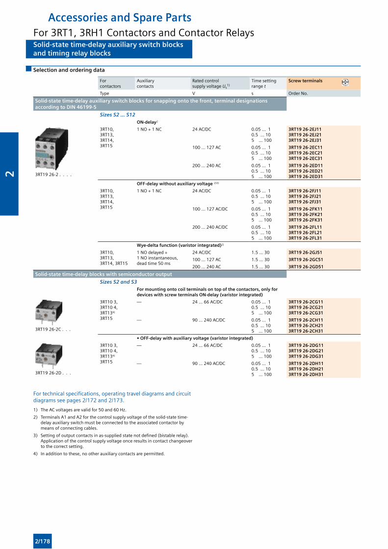
Solid-state time-delay auxiliary switch blocksand timing relay blocks
Solid-state time-delay auxiliary switch blocksand timing relay blocks
Accessories and Spare PartsFor 3RT1, 3RH1 Contactors and Contactor Relays
Selection and ordering data
For contactors
Auxiliary contacts
Rated controlsupply voltage Us
1)Time setting range t
Screw terminals
Type V s Order No.
Solid-state time-delay auxiliary switch blocks for snapping onto the front, terminal designations according to DIN 46199-5
Sizes S2 ... S12 ON-delay2
3RT19 26-2 . . . .
3RT10, 3RT13, 3RT14, 3RT15
1 NO + 1 NC 24 AC/DC 0.05 ... 10.5 ... 105 ... 100
3RT19 26-2EJ113RT19 26-2EJ213RT19 26-2EJ31
100 ... 127 AC 0.05 ... 10.5 ... 105 ... 100
3RT19 26-2EC113RT19 26-2EC213RT19 26-2EC31
200 ... 240 AC 0.05 ... 10.5 ... 105 ... 100
3RT19 26-2ED113RT19 26-2ED213RT19 26-2ED31
OFF-delay without auxiliary voltage 2)3)
3RT10, 3RT13, 3RT14, 3RT15
1 NO + 1 NC 24 AC/DC 0.05 ... 10.5 ... 105 ... 100
3RT19 26-2FJ113RT19 26-2FJ213RT19 26-2FJ31
100 ... 127 AC/DC 0.05 ... 10.5 ... 105 ... 100
3RT19 26-2FK113RT19 26-2FK213RT19 26-2FK31
200 ... 240 AC/DC 0.05 ... 10.5 ... 105 ... 100
3RT19 26-2FL113RT19 26-2FL213RT19 26-2FL31
Wye-delta function (varistor integrated)2)
3RT10, 3RT13, 3RT14, 3RT15
1 NO delayed + 1 NO instantaneous, dead time 50 ms
24 AC/DC 1.5 ... 30 3RT19 26-2GJ51
100 ... 127 AC 1.5 ... 30 3RT19 26-2GC51
200 ... 240 AC 1.5 ... 30 3RT19 26-2GD51
Solid-state time-delay blocks with semiconductor output
Sizes S2 and S3For mounting onto coil terminals on top of the contactors, only for devices with screw terminals ON-delay (varistor integrated)
3RT19 26-2C . . .
3RT10 3, 3RT10 4, 3RT134)
3RT15
— 24 ... 66 AC/DC 0.05 ... 10.5 ... 105 ... 100
3RT19 26-2CG113RT19 26-2CG213RT19 26-2CG31
— 90 ... 240 AC/DC 0.05 ... 10.5 ... 105 ... 100
3RT19 26-2CH113RT19 26-2CH213RT19 26-2CH31
• OFF-delay with auxiliary voltage (varistor integrated)
3RT19 26-2D . . .
3RT10 3, 3RT10 4, 3RT134)
3RT15
— 24 ... 66 AC/DC 0.05 ... 10.5 ... 105 ... 100
3RT19 26-2DG113RT19 26-2DG213RT19 26-2DG31
— 90 ... 240 AC/DC 0.05 ... 10.5 ... 105 ... 100
3RT19 26-2DH113RT19 26-2DH213RT19 26-2DH31
For technical specifications, operating travel diagrams and circuit diagrams see pages 2/172 and 2/173.
1) The AC voltages are valid for 50 and 60 Hz.
2) Terminals A1 and A2 for the control supply voltage of the solid-state time-delay auxiliary switch must be connected to the associated contactor by means of connecting cables.
3) Setting of output contacts in as-supplied state not defined (bistable relay). Application of the control supply voltage once results in contact changeover to the correct setting.
4) In addition to these, no other auxiliary contacts are permitted.
2/178
2
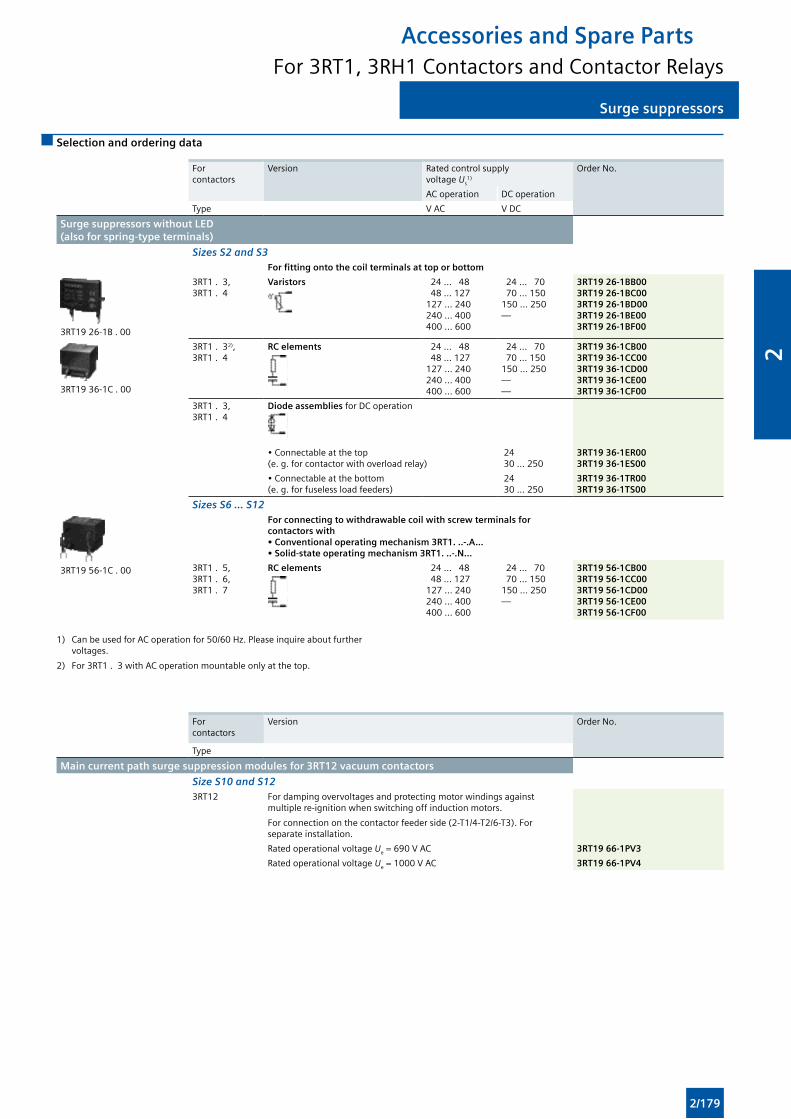
Surge suppressorsSurge suppressors
Accessories and Spare PartsFor 3RT1, 3RH1 Contactors and Contactor Relays
Selection and ordering data
For contactors
Version Rated control supply voltage Us
1)
Order No.
AC operation DC operation
Type V AC V DC
Surge suppressors without LED (also for spring-type terminals)
Sizes S2 and S3For fitting onto the coil terminals at top or bottom
3RT19 26-1B . 00
3RT1 . 3, 3RT1 . 4
Varistors 24 ... 48 48 ... 127127 ... 240240 ... 400400 ... 600
24 ... 70 70 ... 150150 ... 250—
3RT19 26-1BB003RT19 26-1BC003RT19 26-1BD003RT19 26-1BE003RT19 26-1BF00
3RT19 36-1C . 00
3RT1 . 32), 3RT1 . 4
RC elements 24 ... 48 48 ... 127127 ... 240240 ... 400400 ... 600
24 ... 70 70 ... 150150 ... 250——
3RT19 36-1CB003RT19 36-1CC003RT19 36-1CD003RT19 36-1CE003RT19 36-1CF00
3RT1 . 3, 3RT1 . 4
Diode assemblies for DC operation
• Connectable at the top (e. g. for contactor with overload relay)
24 30 ... 250
3RT19 36-1ER003RT19 36-1ES00
• Connectable at the bottom (e. g. for fuseless load feeders)
24 30 ... 250
3RT19 36-1TR003RT19 36-1TS00
Sizes S6 ... S12
3RT19 56-1C . 00
For connecting to withdrawable coil with screw terminals for contactors with • Conventional operating mechanism 3RT1. ..-.A... • Solid-state operating mechanism 3RT1. ..-.N...
3RT1 . 5, 3RT1 . 6, 3RT1 . 7
RC elements 24 ... 48 48 ... 127127 ... 240240 ... 400400 ... 600
24 ... 70 70 ... 150150 ... 250—
3RT19 56-1CB003RT19 56-1CC003RT19 56-1CD003RT19 56-1CE003RT19 56-1CF00
1) Can be used for AC operation for 50/60 Hz. Please inquire about further voltages.
2) For 3RT1 . 3 with AC operation mountable only at the top.
For contactors
Version Order No.
Type
Main current path surge suppression modules for 3RT12 vacuum contactors
Size S10 and S123RT12 For damping overvoltages and protecting motor windings against
multiple re-ignition when switching off induction motors.
For connection on the contactor feeder side (2-T1/4-T2/6-T3). For separate installation.
Rated operational voltage Ue = 690 V AC 3RT19 66-1PV3
Rated operational voltage Ue = 1000 V AC 3RT19 66-1PV4
2/179
2
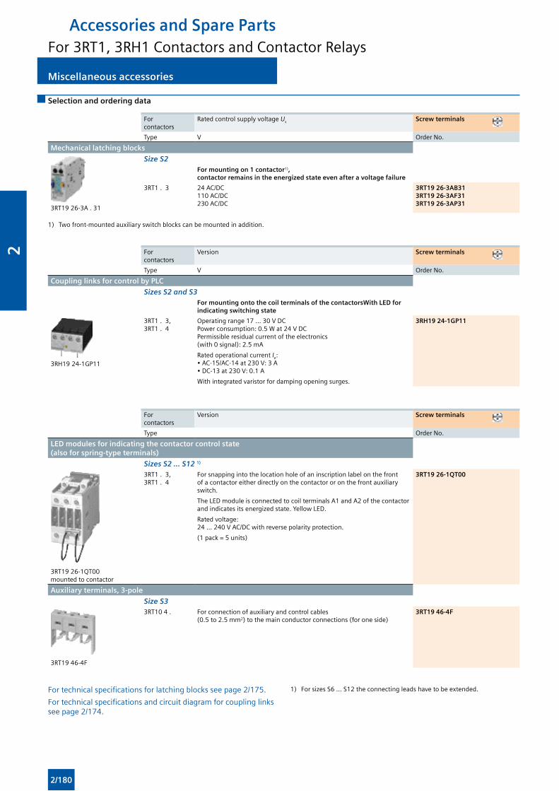
Miscellaneous accessories Miscellaneous accessories
Accessories and Spare PartsFor 3RT1, 3RH1 Contactors and Contactor Relays
Selection and ordering data
For contactors
Rated control supply voltage Us Screw terminals
Type V Order No.
Mechanical latching blocks
3RT19 26-3A . 31
Size S2For mounting on 1 contactor1), contactor remains in the energized state even after a voltage failure
3RT1 . 3 24 AC/DC110 AC/DC230 AC/DC
3RT19 26-3AB313RT19 26-3AF313RT19 26-3AP31
1) Two front-mounted auxiliary switch blocks can be mounted in addition.
For contactors
Version Screw terminals
Type V Order No.
Coupling links for control by PLC
Sizes S2 and S3For mounting onto the coil terminals of the contactorsWith LED for indicating switching state
3RH19 24-1GP11
3RT1 . 3, 3RT1 . 4
Operating range 17 ... 30 V DC Power consumption: 0.5 W at 24 V DC Permissible residual current of the electronics (with 0 signal): 2.5 mA
Rated operational current Ie: • AC-15/AC-14 at 230 V: 3 A • DC-13 at 230 V: 0.1 A
With integrated varistor for damping opening surges.
3RH19 24-1GP11
For contactors
Version Screw terminals
Type Order No.
LED modules for indicating the contactor control state (also for spring-type terminals)
Sizes S2 ... S12 1)
3RT19 26-1QT00 mounted to contactor
3RT1 . 3, 3RT1 . 4
For snapping into the location hole of an inscription label on the front of a contactor either directly on the contactor or on the front auxiliary switch.
The LED module is connected to coil terminals A1 and A2 of the contactor and indicates its energized state. Yellow LED.
Rated voltage: 24 ... 240 V AC/DC with reverse polarity protection.
(1 pack = 5 units)
3RT19 26-1QT00
Auxiliary terminals, 3-pole
Size S3
3RT19 46-4F
3RT10 4 . For connection of auxiliary and control cables (0.5 to 2.5 mm2) to the main conductor connections (for one side)
3RT19 46-4F
For technical specifications for latching blocks see page 2/175.
For technical specifications and circuit diagram for coupling links see page 2/174.
1) For sizes S6 ... S12 the connecting leads have to be extended.
2/180
2
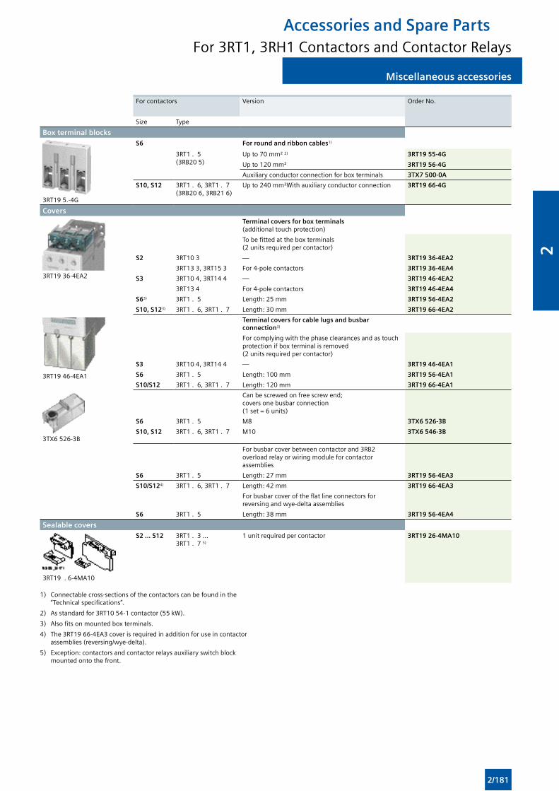
Miscellaneous accessoriesMiscellaneous accessories
Accessories and Spare PartsFor 3RT1, 3RH1 Contactors and Contactor Relays
For contactors Version Order No.
Size Type
Box terminal blocks
3RT19 5.-4G
S6 For round and ribbon cables1)
3RT1 . 5 (3RB20 5)
Up to 70 mm² 2) 3RT19 55-4G
Up to 120 mm² 3RT19 56-4G
Auxiliary conductor connection for box terminals 3TX7 500-0A
S10, S12 3RT1 . 6, 3RT1 . 7 (3RB20 6, 3RB21 6)
Up to 240 mm²With auxiliary conductor connection 3RT19 66-4G
Covers
3RT19 36-4EA2
Terminal covers for box terminals (additional touch protection)
To be fitted at the box terminals (2 units required per contactor)
S2 3RT10 3 — 3RT19 36-4EA2
3RT13 3, 3RT15 3 For 4-pole contactors 3RT19 36-4EA4
S3 3RT10 4, 3RT14 4 — 3RT19 46-4EA2
3RT13 4 For 4-pole contactors 3RT19 46-4EA4
S63) 3RT1 . 5 Length: 25 mm 3RT19 56-4EA2
S10, S123) 3RT1 . 6, 3RT1 . 7 Length: 30 mm 3RT19 66-4EA2
3RT19 46-4EA1
Terminal covers for cable lugs and busbar connection3)
For complying with the phase clearances and as touch protection if box terminal is removed (2 units required per contactor)
S3 3RT10 4, 3RT14 4 — 3RT19 46-4EA1
S6 3RT1 . 5 Length: 100 mm 3RT19 56-4EA1
S10/S12 3RT1 . 6, 3RT1 . 7 Length: 120 mm 3RT19 66-4EA1
3TX6 526-3B
Can be screwed on free screw end; covers one busbar connection (1 set = 6 units)
S6 3RT1 . 5 M8 3TX6 526-3B
S10, S12 3RT1 . 6, 3RT1 . 7 M10 3TX6 546-3B
For busbar cover between contactor and 3RB2 overload relay or wiring module for contactor assemblies
S6 3RT1 . 5 Length: 27 mm 3RT19 56-4EA3
S10/S124) 3RT1 . 6, 3RT1 . 7 Length: 42 mm 3RT19 66-4EA3
For busbar cover of the flat line connectors for reversing and wye-delta assemblies
S6 3RT1 . 5 Length: 38 mm 3RT19 56-4EA4
Sealable covers
3RT19 . 6-4MA10
S2 ... S12 3RT1 . 3 ... 3RT1 . 7 5)
1 unit required per contactor 3RT19 26-4MA10
1) Connectable cross-sections of the contactors can be found in the “Technical specifications”.
2) As standard for 3RT10 54-1 contactor (55 kW).
3) Also fits on mounted box terminals.
4) The 3RT19 66-4EA3 cover is required in addition for use in contactor assemblies (reversing/wye-delta).
5) Exception: contactors and contactor relays auxiliary switch block mounted onto the front.
2/181
2
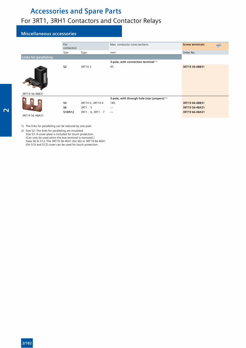
Miscellaneous accessories Miscellaneous accessories
Accessories and Spare PartsFor 3RT1, 3RH1 Contactors and Contactor Relays
For contactors
Max. conductor cross-sections Screw terminals
Size Type mm2 Order No.
Links for paralleling3-pole, with connection terminal1)2)
3RT19 36-4BB31
S2 3RT10 3 95 3RT19 36-4BB31
3RT19 56-4BA31
3-pole, with through hole (star jumpers)1)2)
S3 3RT10 4, 3RT14 4 185 3RT19 46-4BB31
S6 3RT1 . 5 — 3RT19 56-4BA31
S10/S12 3RT1 . 6, 3RT1 . 7 — 3RT19 66-4BA31
1) The links for paralleling can be reduced by one pole.
2) Size S2: The links for paralleling are insulated. Size S3: A cover plate is included for touch protection. (Can only be used when the box terminal is removed.) Sizes S6 to S12: The 3RT19 56-4EA1 (for S6) or 3RT19 66-4EA1 (for S10 and S12) cover can be used for touch protection.
2/182
2
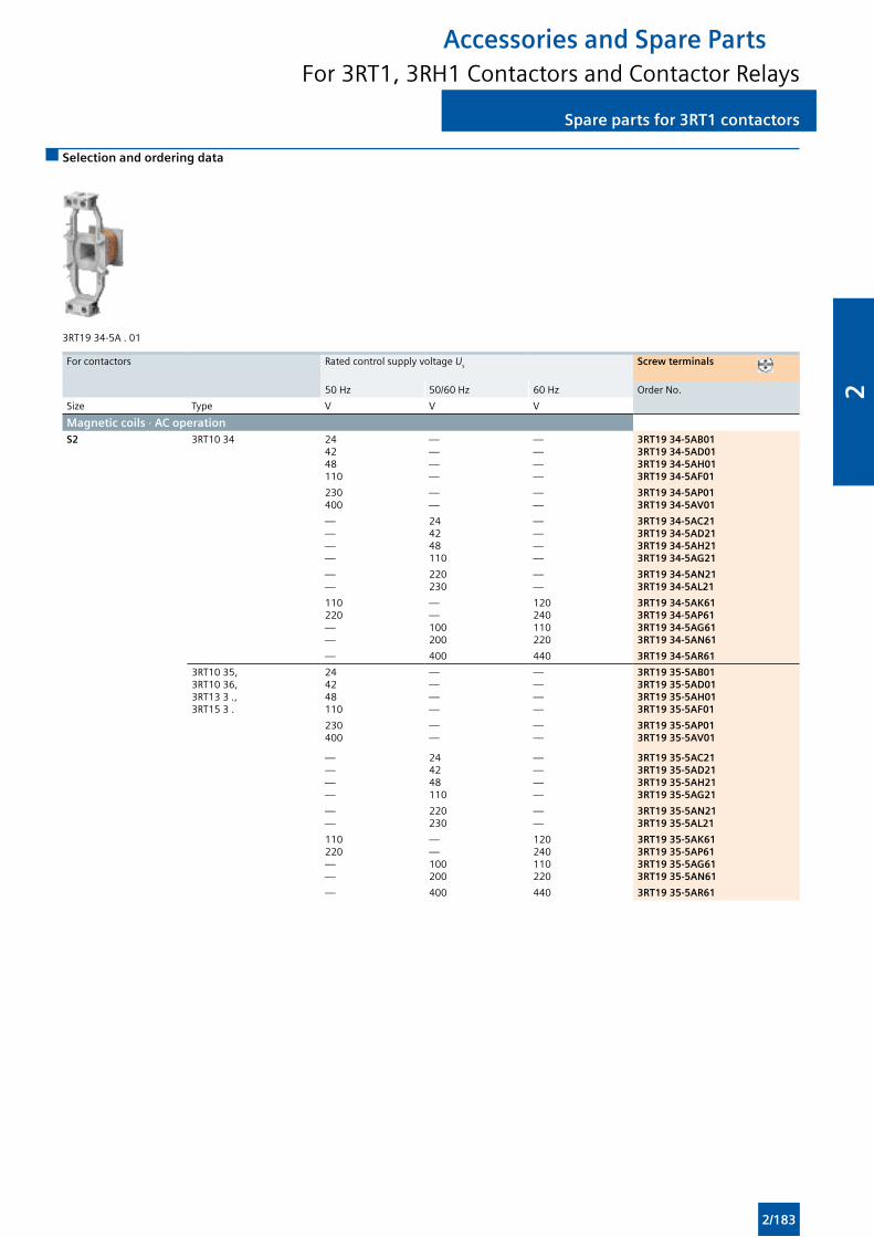
Spare parts for 3RT1 contactorsSpare parts for 3RT1 contactors
Accessories and Spare PartsFor 3RT1, 3RH1 Contactors and Contactor Relays
Selection and ordering data
3RT19 34-5A . 01
For contactors Rated control supply voltage Us Screw terminals
50 Hz 50/60 Hz 60 Hz Order No.
Size Type V V V
Magnetic coils · AC operationS2 3RT10 34 24
4248110
————
————
3RT19 34-5AB013RT19 34-5AD013RT19 34-5AH013RT19 34-5AF01
230400
——
——
3RT19 34-5AP013RT19 34-5AV01
————
244248110
————
3RT19 34-5AC213RT19 34-5AD213RT19 34-5AH213RT19 34-5AG21
——
220230
——
3RT19 34-5AN213RT19 34-5AL21
110220——
——100200
120240110220
3RT19 34-5AK613RT19 34-5AP613RT19 34-5AG613RT19 34-5AN61
— 400 440 3RT19 34-5AR61
3RT10 35, 3RT10 36, 3RT13 3 ., 3RT15 3 .
244248110
————
————
3RT19 35-5AB013RT19 35-5AD013RT19 35-5AH013RT19 35-5AF01
230400
——
——
3RT19 35-5AP013RT19 35-5AV01
————
244248110
————
3RT19 35-5AC213RT19 35-5AD213RT19 35-5AH213RT19 35-5AG21
——
220230
——
3RT19 35-5AN213RT19 35-5AL21
110220——
——100200
120240110220
3RT19 35-5AK613RT19 35-5AP613RT19 35-5AG613RT19 35-5AN61
— 400 440 3RT19 35-5AR61
2/183
2
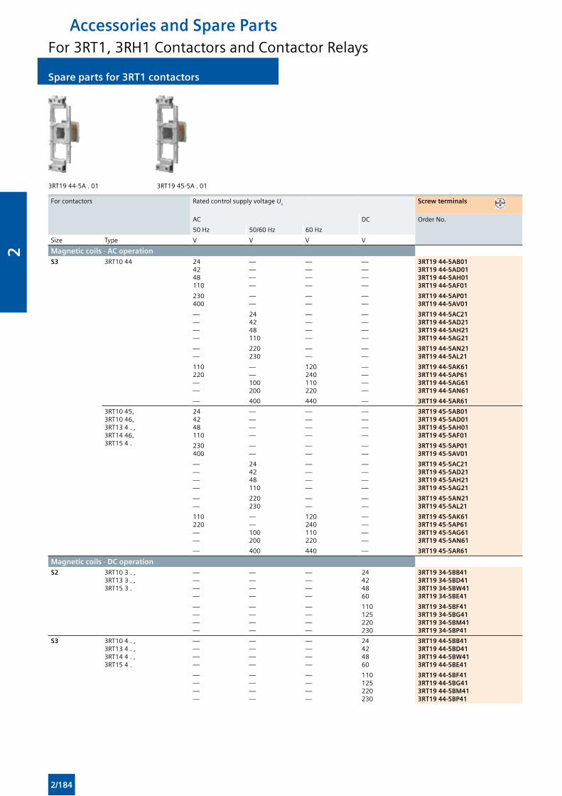
Spare parts for 3RT1 contactors Spare parts for 3RT1 contactors
Accessories and Spare PartsFor 3RT1, 3RH1 Contactors and Contactor Relays
3RT19 44-5A . 01 3RT19 45-5A . 01
For contactors Rated control supply voltage Us Screw terminals
AC DC Order No.
50 Hz 50/60 Hz 60 Hz
Size Type V V V V
Magnetic coils · AC operationS3 3RT10 44 24
4248110
————
————
————
3RT19 44-5AB013RT19 44-5AD013RT19 44-5AH013RT19 44-5AF01
230400
——
——
——
3RT19 44-5AP013RT19 44-5AV01
————
244248110
————
————
3RT19 44-5AC213RT19 44-5AD213RT19 44-5AH213RT19 44-5AG21
——
220230
——
——
3RT19 44-5AN213RT19 44-5AL21
110220——
——100200
120240110220
————
3RT19 44-5AK613RT19 44-5AP613RT19 44-5AG613RT19 44-5AN61
— 400 440 — 3RT19 44-5AR61
3RT10 45, 3RT10 46, 3RT13 4 . , 3RT14 46, 3RT15 4 .
244248110
————
————
————
3RT19 45-5AB013RT19 45-5AD013RT19 45-5AH013RT19 45-5AF01
230400
——
——
——
3RT19 45-5AP013RT19 45-5AV01
————
244248110
————
————
3RT19 45-5AC213RT19 45-5AD213RT19 45-5AH213RT19 45-5AG21
——
220230
——
——
3RT19 45-5AN213RT19 45-5AL21
110220——
——100200
120240110220
————
3RT19 45-5AK613RT19 45-5AP613RT19 45-5AG613RT19 45-5AN61
— 400 440 — 3RT19 45-5AR61
Magnetic coils · DC operationS2 3RT10 3 . ,
3RT13 3 . , 3RT15 3 .
————
————
————
24424860
3RT19 34-5BB413RT19 34-5BD413RT19 34-5BW413RT19 34-5BE41
————
————
————
110125220230
3RT19 34-5BF413RT19 34-5BG413RT19 34-5BM413RT19 34-5BP41
S3 3RT10 4 . , 3RT13 4 . ,3RT14 4 . , 3RT15 4 .
————
————
————
24424860
3RT19 44-5BB413RT19 44-5BD413RT19 44-5BW413RT19 44-5BE41
————
————
————
110125220230
3RT19 44-5BF413RT19 44-5BG413RT19 44-5BM413RT19 44-5BP41
2/184
2
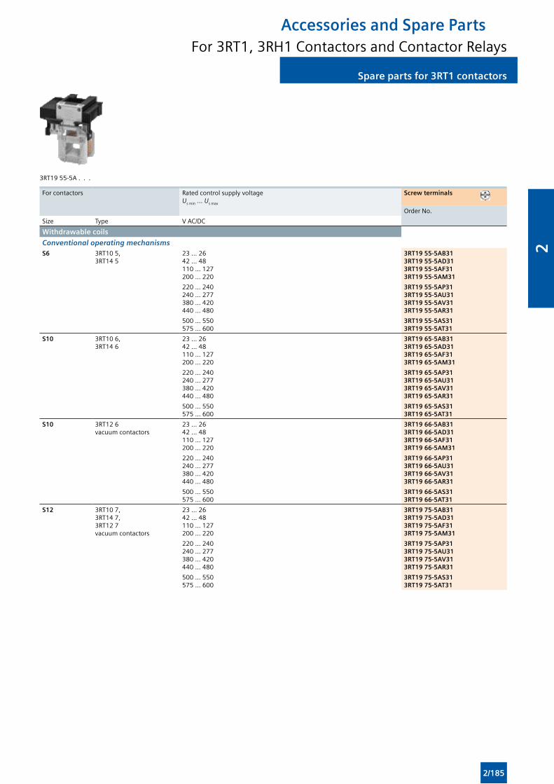
Spare parts for 3RT1 contactorsSpare parts for 3RT1 contactors
Accessories and Spare PartsFor 3RT1, 3RH1 Contactors and Contactor Relays
3RT19 55-5A . . .
For contactors Rated control supply voltage Us min ... Us max
Screw terminals
Order No.
Size Type V AC/DC
Withdrawable coils
Conventional operating mechanismsS6 3RT10 5,
3RT14 523 ... 2642 ... 48110 ... 127200 ... 220
3RT19 55-5AB313RT19 55-5AD313RT19 55-5AF313RT19 55-5AM31
220 ... 240240 ... 277380 ... 420440 ... 480
3RT19 55-5AP313RT19 55-5AU313RT19 55-5AV313RT19 55-5AR31
500 ... 550575 ... 600
3RT19 55-5AS313RT19 55-5AT31
S10 3RT10 6, 3RT14 6
23 ... 2642 ... 48110 ... 127200 ... 220
3RT19 65-5AB313RT19 65-5AD313RT19 65-5AF313RT19 65-5AM31
220 ... 240240 ... 277380 ... 420440 ... 480
3RT19 65-5AP313RT19 65-5AU313RT19 65-5AV313RT19 65-5AR31
500 ... 550575 ... 600
3RT19 65-5AS313RT19 65-5AT31
S10 3RT12 6 vacuum contactors
23 ... 2642 ... 48110 ... 127200 ... 220
3RT19 66-5AB313RT19 66-5AD313RT19 66-5AF313RT19 66-5AM31
220 ... 240240 ... 277380 ... 420440 ... 480
3RT19 66-5AP313RT19 66-5AU313RT19 66-5AV313RT19 66-5AR31
500 ... 550575 ... 600
3RT19 66-5AS313RT19 66-5AT31
S12 3RT10 7, 3RT14 7, 3RT12 7 vacuum contactors
23 ... 2642 ... 48110 ... 127200 ... 220
3RT19 75-5AB313RT19 75-5AD313RT19 75-5AF313RT19 75-5AM31
220 ... 240240 ... 277380 ... 420440 ... 480
3RT19 75-5AP313RT19 75-5AU313RT19 75-5AV313RT19 75-5AR31
500 ... 550575 ... 600
3RT19 75-5AS313RT19 75-5AT31
2/185
2
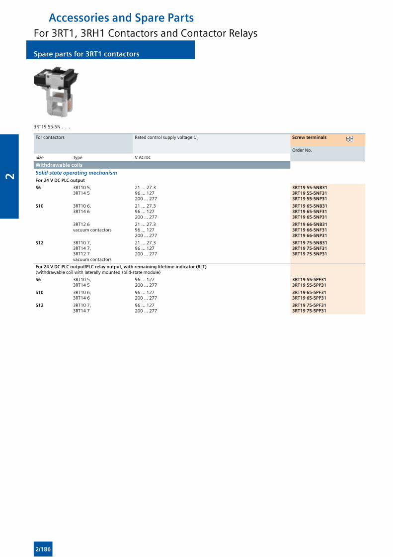
Spare parts for 3RT1 contactors Spare parts for 3RT1 contactors
Accessories and Spare PartsFor 3RT1, 3RH1 Contactors and Contactor Relays
3RT19 55-5N . . .
For contactors Rated control supply voltage Us Screw terminals
Order No.
Size Type V AC/DC
Withdrawable coils
Solid-state operating mechanismFor 24 V DC PLC output
S6 3RT10 5, 3RT14 5
21 ... 27.396 ... 127200 ... 277
3RT19 55-5NB313RT19 55-5NF313RT19 55-5NP31
S10 3RT10 6, 3RT14 6
21 ... 27.396 ... 127200 ... 277
3RT19 65-5NB313RT19 65-5NF313RT19 65-5NP31
3RT12 6 vacuum contactors
21 ... 27.396 ... 127200 ... 277
3RT19 66-5NB313RT19 66-5NF313RT19 66-5NP31
S12 3RT10 7, 3RT14 7, 3RT12 7 vacuum contactors
21 ... 27.396 ... 127200 ... 277
3RT19 75-5NB313RT19 75-5NF313RT19 75-5NP31
For 24 V DC PLC output/PLC relay output, with remaining lifetime indicator (RLT) (withdrawable coil with laterally mounted solid-state module)
S6 3RT10 5, 3RT14 5
96 ... 127200 ... 277
3RT19 55-5PF313RT19 55-5PP31
S10 3RT10 6, 3RT14 6
96 ... 127200 ... 277
3RT19 65-5PF313RT19 65-5PP31
S12 3RT10 7, 3RT14 7
96 ... 127200 ... 277
3RT19 75-5PF313RT19 75-5PP31
2/186
2
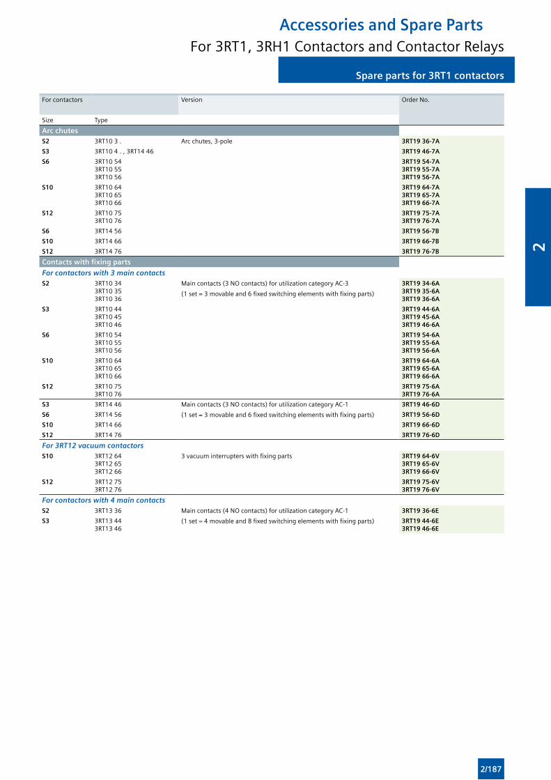
Spare parts for 3RT1 contactorsSpare parts for 3RT1 contactors
Accessories and Spare PartsFor 3RT1, 3RH1 Contactors and Contactor Relays
For contactors Version Order No.
Size Type
Arc chutesS2 3RT10 3 . Arc chutes, 3-pole 3RT19 36-7A
S3 3RT10 4 . , 3RT14 46 3RT19 46-7A
S6 3RT10 543RT10 553RT10 56
3RT19 54-7A3RT19 55-7A3RT19 56-7A
S10 3RT10 643RT10 653RT10 66
3RT19 64-7A3RT19 65-7A3RT19 66-7A
S12 3RT10 753RT10 76
3RT19 75-7A3RT19 76-7A
S6 3RT14 56 3RT19 56-7B
S10 3RT14 66 3RT19 66-7B
S12 3RT14 76 3RT19 76-7B
Contacts with fixing parts
For contactors with 3 main contactsS2 3RT10 34
3RT10 353RT10 36
Main contacts (3 NO contacts) for utilization category AC-3
(1 set = 3 movable and 6 fixed switching elements with fixing parts)
3RT19 34-6A3RT19 35-6A3RT19 36-6A
S3 3RT10 443RT10 453RT10 46
3RT19 44-6A3RT19 45-6A3RT19 46-6A
S6 3RT10 543RT10 553RT10 56
3RT19 54-6A3RT19 55-6A3RT19 56-6A
S10 3RT10 643RT10 653RT10 66
3RT19 64-6A3RT19 65-6A3RT19 66-6A
S12 3RT10 753RT10 76
3RT19 75-6A3RT19 76-6A
S3 3RT14 46 Main contacts (3 NO contacts) for utilization category AC-1
(1 set = 3 movable and 6 fixed switching elements with fixing parts)
3RT19 46-6D
S6 3RT14 56 3RT19 56-6D
S10 3RT14 66 3RT19 66-6D
S12 3RT14 76 3RT19 76-6D
For 3RT12 vacuum contactorsS10 3RT12 64
3RT12 653RT12 66
3 vacuum interrupters with fixing parts 3RT19 64-6V3RT19 65-6V3RT19 66-6V
S12 3RT12 753RT12 76
3RT19 75-6V3RT19 76-6V
For contactors with 4 main contactsS2 3RT13 36 Main contacts (4 NO contacts) for utilization category AC-1
(1 set = 4 movable and 8 fixed switching elements with fixing parts)
3RT19 36-6E
S3 3RT13 443RT13 46
3RT19 44-6E3RT19 46-6E
2/187
2
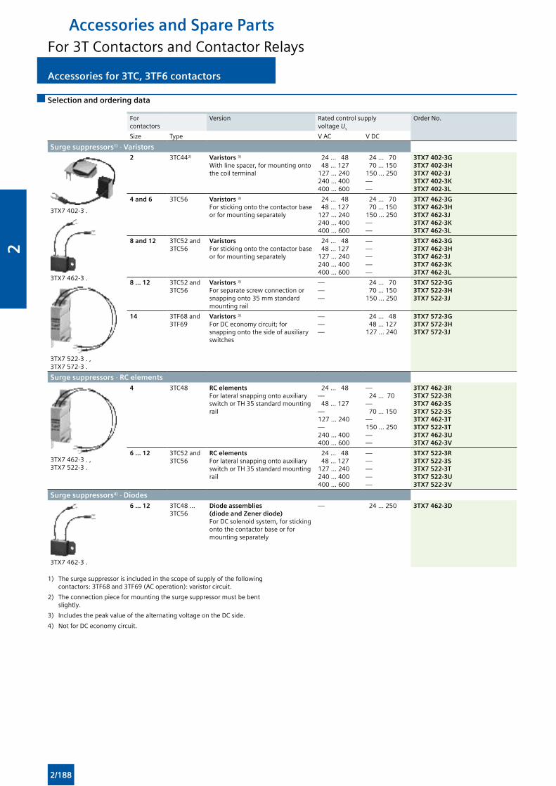
Accessories for 3TC, 3TF6 contactors Accessories for 3TC, 3TF6 contactors
Accessories and Spare PartsFor 3T Contactors and Contactor Relays
Selection and ordering data
For contactors
Version Rated control supply voltage Us
Order No.
Size Type V AC V DC
Surge suppressors1) · Varistors
3TX7 402-3 .
3TX7 462-3 .
3TX7 522-3 . ,3TX7 572-3 .
2 3TC442) Varistors 3) With line spacer, for mounting onto the coil terminal
24 ... 48 48 ... 127127 ... 240240 ... 400400 ... 600
24 ... 70 70 ... 150150 ... 250——
3TX7 402-3G3TX7 402-3H3TX7 402-3J3TX7 402-3K3TX7 402-3L
4 and 6 3TC56 Varistors 3) For sticking onto the contactor base or for mounting separately
24 ... 48 48 ... 127127 ... 240240 ... 400400 ... 600
24 ... 70 70 ... 150150 ... 250——
3TX7 462-3G3TX7 462-3H3TX7 462-3J3TX7 462-3K3TX7 462-3L
8 and 12 3TC52 and 3TC56
Varistors For sticking onto the contactor base or for mounting separately
24 ... 48 48 ... 127127 ... 240240 ... 400400 ... 600
—————
3TX7 462-3G3TX7 462-3H3TX7 462-3J3TX7 462-3K3TX7 462-3L
8 ... 12 3TC52 and 3TC56
Varistors 3) For separate screw connection or snapping onto 35 mm standard mounting rail
———
24 ... 70 70 ... 150150 ... 250
3TX7 522-3G3TX7 522-3H3TX7 522-3J
14 3TF68 and 3TF69
Varistors 3) For DC economy circuit; for snapping onto the side of auxiliary switches
———
24 ... 48 48 ... 127127 ... 240
3TX7 572-3G3TX7 572-3H3TX7 572-3J
Surge suppressors · RC elements
3TX7 462-3 . , 3TX7 522-3 .
4 3TC48 RC elements For lateral snapping onto auxiliary switch or TH 35 standard mounting rail
24 ... 48— 48 ... 127— 127 ... 240— 240 ... 400400 ... 600
— 24 ... 70— 70 ... 150—150 ... 250——
3TX7 462-3R3TX7 522-3R3TX7 462-3S3TX7 522-3S3TX7 462-3T3TX7 522-3T3TX7 462-3U3TX7 462-3V
6 ... 12 3TC52 and 3TC56
RC elements For lateral snapping onto auxiliary switch or TH 35 standard mounting rail
24 ... 48 48 ... 127127 ... 240240 ... 400400 ... 600
—————
3TX7 522-3R3TX7 522-3S3TX7 522-3T3TX7 522-3U3TX7 522-3V
Surge suppressors4) · Diodes
3TX7 462-3 .
6 ... 12 3TC48 ... 3TC56
Diode assemblies (diode and Zener diode) For DC solenoid system, for sticking onto the contactor base or for mounting separately
— 24 ... 250 3TX7 462-3D
1) The surge suppressor is included in the scope of supply of the following contactors: 3TF68 and 3TF69 (AC operation): varistor circuit.
2) The connection piece for mounting the surge suppressor must be bent slightly.
3) Includes the peak value of the alternating voltage on the DC side.
4) Not for DC economy circuit.
2/188
2
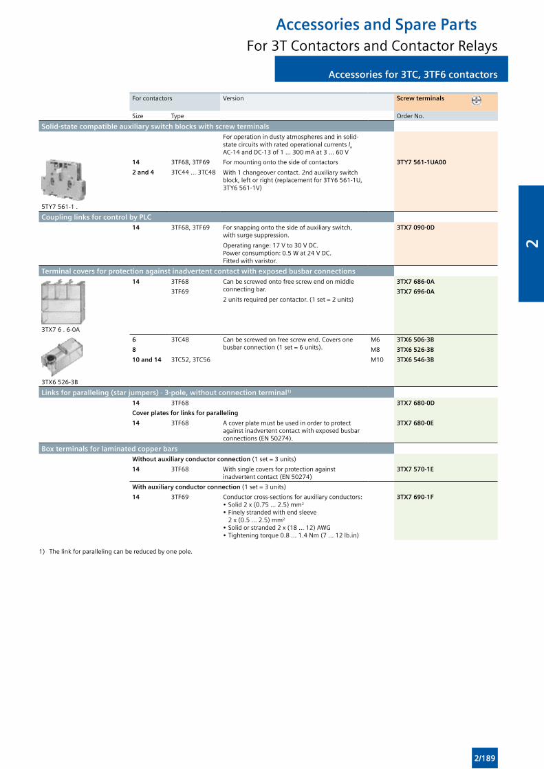
Accessories for 3TC, 3TF6 contactorsAccessories for 3TC, 3TF6 contactors
Accessories and Spare PartsFor 3T Contactors and Contactor Relays
For contactors Version Screw terminals
Size Type Order No.
Solid-state compatible auxiliary switch blocks with screw terminalsFor operation in dusty atmospheres and in solid-state circuits with rated operational currents Ie AC-14 and DC-13 of 1 ... 300 mA at 3 ... 60 V
5TY7 561-1 .
14 3TF68, 3TF69 For mounting onto the side of contactors
With 1 changeover contact. 2nd auxiliary switch block, left or right (replacement for 3TY6 561-1U, 3TY6 561-1V)
3TY7 561-1UA00
2 and 4 3TC44 ... 3TC48
Coupling links for control by PLC 14 3TF68, 3TF69 For snapping onto the side of auxiliary switch,
with surge suppression.
Operating range: 17 V to 30 V DC. Power consumption: 0.5 W at 24 V DC. Fitted with varistor.
3TX7 090-0D
Terminal covers for protection against inadvertent contact with exposed busbar connections
3TX7 6 . 6-0A
14 3TF68 Can be screwed onto free screw end on middle connecting bar.
2 units required per contactor. (1 set = 2 units)
3TX7 686-0A
3TF69 3TX7 696-0A
3TX6 526-3B
6 3TC48 Can be screwed on free screw end. Covers one busbar connection (1 set = 6 units).
M6 3TX6 506-3B
8 M8 3TX6 526-3B
10 and 14 3TC52, 3TC56 M10 3TX6 546-3B
Links for paralleling (star jumpers) · 3-pole, without connection terminal1) 14 3TF68 3TX7 680-0D
Cover plates for links for paralleling
14 3TF68 A cover plate must be used in order to protect against inadvertent contact with exposed busbar connections (EN 50274).
3TX7 680-0E
Box terminals for laminated copper barsWithout auxiliary conductor connection (1 set = 3 units)
14 3TF68 With single covers for protection against inadvertent contact (EN 50274)
3TX7 570-1E
With auxiliary conductor connection (1 set = 3 units)
14 3TF69 Conductor cross-sections for auxiliary conductors:• Solid 2 x (0.75 ... 2.5) mm2
• Finely stranded with end sleeve 2 x (0.5 ... 2.5) mm2
• Solid or stranded 2 x (18 ... 12) AWG• Tightening torque 0.8 ... 1.4 Nm (7 ... 12 lb.in)
3TX7 690-1F
1) The link for paralleling can be reduced by one pole.
2/189
2
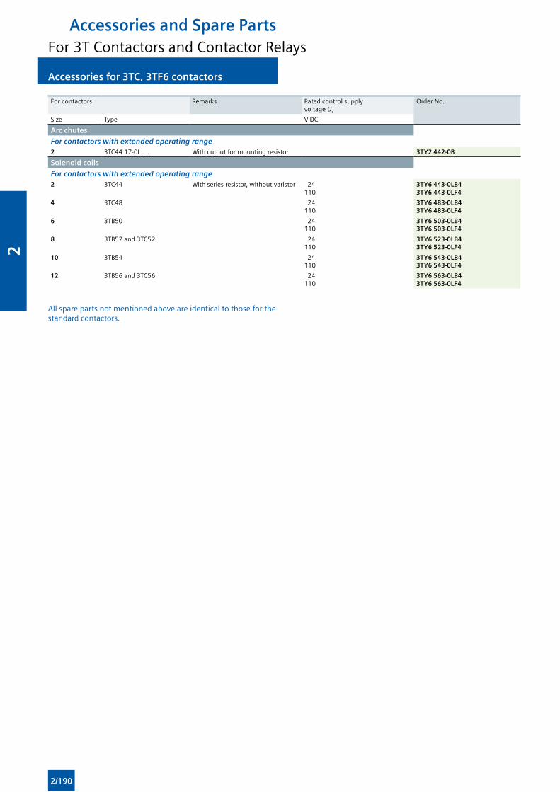
Accessories for 3TC, 3TF6 contactors Accessories for 3TC, 3TF6 contactors
Accessories and Spare PartsFor 3T Contactors and Contactor Relays
For contactors Remarks Rated control supply voltage Us
Order No.
Size Type V DC
Arc chutes
For contactors with extended operating range2 3TC44 17-0L . . With cutout for mounting resistor 3TY2 442-0B
Solenoid coils
For contactors with extended operating range2 3TC44 With series resistor, without varistor 24
1103TY6 443-0LB43TY6 443-0LF4
4 3TC48 24110
3TY6 483-0LB43TY6 483-0LF4
6 3TB50 24110
3TY6 503-0LB43TY6 503-0LF4
8 3TB52 and 3TC52 24110
3TY6 523-0LB43TY6 523-0LF4
10 3TB54 24110
3TY6 543-0LB43TY6 543-0LF4
12 3TB56 and 3TC56 24110
3TY6 563-0LB43TY6 563-0LF4
All spare parts not mentioned above are identical to those for the standard contactors.
2/190
2
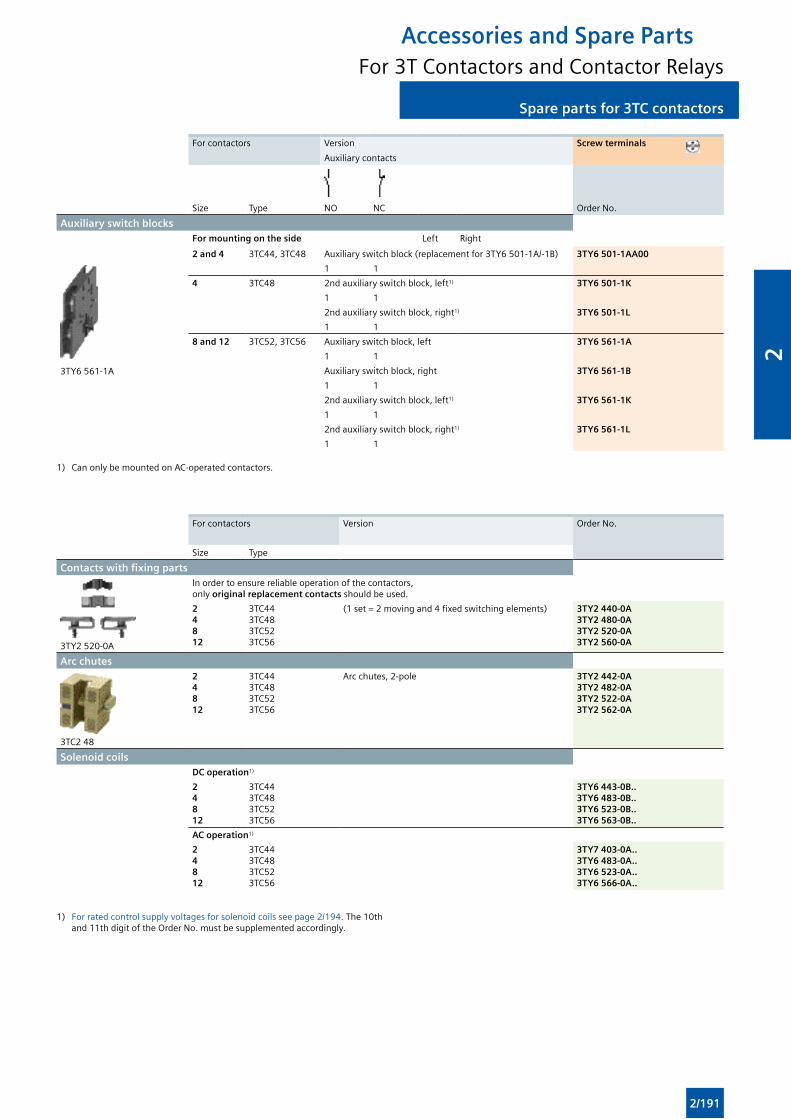
Spare parts for 3TC contactorsSpare parts for 3TC contactors
Accessories and Spare PartsFor 3T Contactors and Contactor Relays
For contactors Version
Auxiliary contacts
Screw terminals
Size Type NO NC Order No.
Auxiliary switch blocksFor mounting on the side Left Right
2 and 4 3TC44, 3TC48 Auxiliary switch block (replacement for 3TY6 501-1A/-1B) 3TY6 501-1AA00
3TY6 561-1A
1 1
4 3TC48 2nd auxiliary switch block, left1) 3TY6 501-1K
1 1
2nd auxiliary switch block, right1) 3TY6 501-1L
1 1
8 and 12 3TC52, 3TC56 Auxiliary switch block, left 3TY6 561-1A
1 1
Auxiliary switch block, right 3TY6 561-1B
1 1
2nd auxiliary switch block, left1) 3TY6 561-1K
1 1
2nd auxiliary switch block, right1) 3TY6 561-1L
1 1
1) Can only be mounted on AC-operated contactors.
For contactors Version Order No.
Size Type
Contacts with fixing parts
3TY2 520-0A
In order to ensure reliable operation of the contactors, only original replacement contacts should be used.
24812
3TC443TC483TC523TC56
(1 set = 2 moving and 4 fixed switching elements) 3TY2 440-0A3TY2 480-0A3TY2 520-0A3TY2 560-0A
Arc chutes
3TC2 48
24812
3TC443TC483TC523TC56
Arc chutes, 2-pole 3TY2 442-0A3TY2 482-0A3TY2 522-0A3TY2 562-0A
Solenoid coilsDC operation1)
24812
3TC443TC483TC523TC56
3TY6 443-0B..3TY6 483-0B..3TY6 523-0B..3TY6 563-0B..
AC operation1)
24812
3TC443TC483TC523TC56
3TY7 403-0A..3TY6 483-0A..3TY6 523-0A..3TY6 566-0A..
1) For rated control supply voltages for solenoid coils see page 2/194. The 10th and 11th digit of the Order No. must be supplemented accordingly.
2/191
2
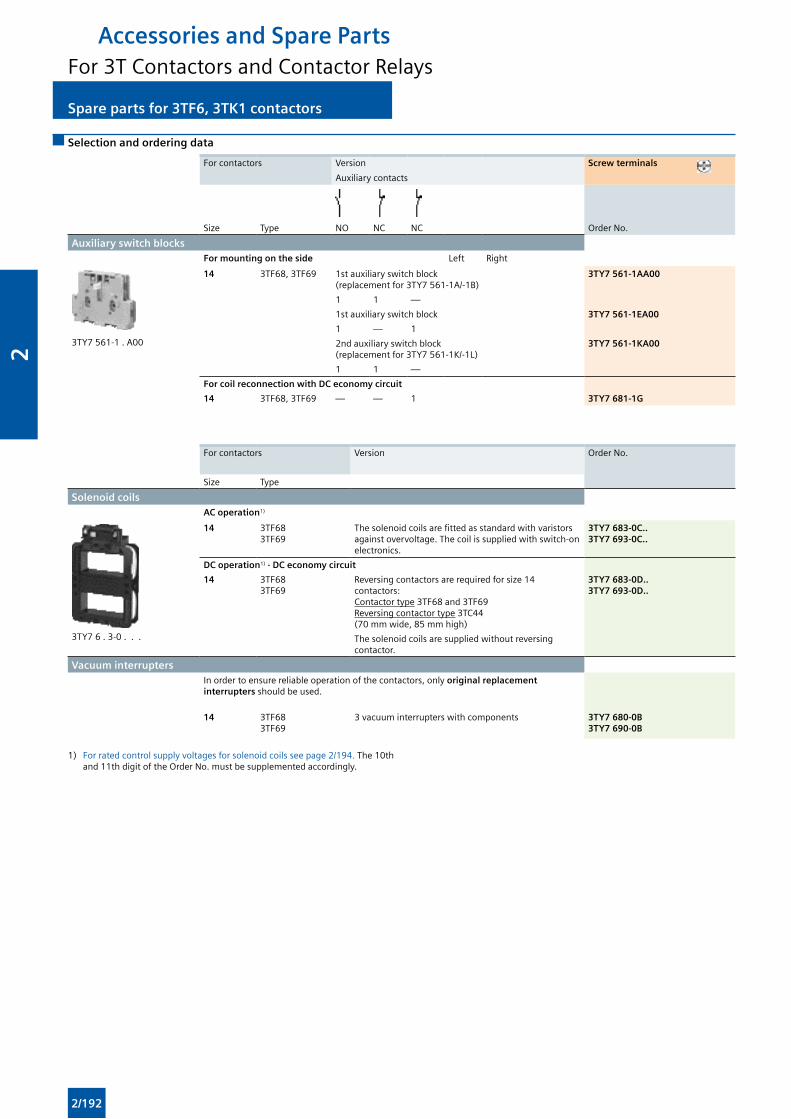
Spare parts for 3TF6, 3TK1 contactors Spare parts for 3TF6, 3TK1 contactors
Accessories and Spare PartsFor 3T Contactors and Contactor Relays
Selection and ordering data
For contactors Version
Auxiliary contacts
Screw terminals
Size Type NO NC NC Order No.
Auxiliary switch blocksFor mounting on the side Left Right
3TY7 561-1 . A00
14 3TF68, 3TF69 1st auxiliary switch block (replacement for 3TY7 561-1A/-1B)
3TY7 561-1AA00
1 1 —
1st auxiliary switch block 3TY7 561-1EA00
1 — 1
2nd auxiliary switch block (replacement for 3TY7 561-1K/-1L)
3TY7 561-1KA00
1 1 —
For coil reconnection with DC economy circuit
14 3TF68, 3TF69 — — 1 3TY7 681-1G
For contactors Version Order No.
Size Type
Solenoid coilsAC operation1)
3TY7 6 . 3-0 . . .
14 3TF683TF69
The solenoid coils are fitted as standard with varistors against overvoltage. The coil is supplied with switch-on electronics.
3TY7 683-0C..3TY7 693-0C..
DC operation1) · DC economy circuit
14 3TF683TF69
Reversing contactors are required for size 14 contactors: Contactor type 3TF68 and 3TF69 Reversing contactor type 3TC44 (70 mm wide, 85 mm high)
3TY7 683-0D..3TY7 693-0D..
The solenoid coils are supplied without reversing contactor.
Vacuum interruptersIn order to ensure reliable operation of the contactors, only original replacement interrupters should be used.
14 3TF683TF69
3 vacuum interrupters with components 3TY7 680-0B3TY7 690-0B
1) For rated control supply voltages for solenoid coils see page 2/194. The 10th and 11th digit of the Order No. must be supplemented accordingly.
2/192
2
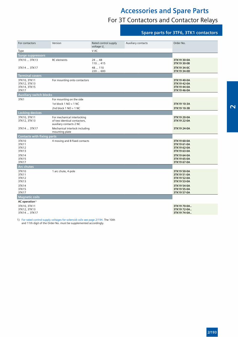
Spare parts for 3TF6, 3TK1 contactorsSpare parts for 3TF6, 3TK1 contactors
Accessories and Spare PartsFor 3T Contactors and Contactor Relays
For contactors Version Rated control supply voltage Us
Auxiliary contacts Order No.
Type V AC
Surge suppressors3TK10 ... 3TK13 RC elements 24 ... 48
110 ... 4153TK19 30-0A3TK19 30-0B
3TK14 ... 3TK17 48 ... 110220 ... 600
3TK19 34-0C3TK19 34-0D
Terminal covers3TK10, 3TK113TK12, 3TK133TK14, 3TK153TK17
For mounting onto contactors 3TK19 40-0A3TK19 42-0A3TK19 44-0A3TK19 46-0A
Auxiliary switch blocks3TK1 For mounting on the side
1st block 1 NO + 1 NC 3TK19 10-3A
2nd block 1 NO + 1 NC 3TK19 10-3B
Locking devices3TK10, 3TK113TK12, 3TK13
For mechanical interlocking of two identical contactors, auxiliary contacts 2 NC
3TK19 20-0A3TK19 22-0A
3TK14 ... 3TK17 Mechanical interlock including mounting plate
3TK19 24-0A
Contacts with fixing parts3TK103TK113TK123TK13
4 moving and 8 fixed contacts 3TK19 60-0A3TK19 61-0A3TK19 62-0A3TK19 63-0A
3TK143TK153TK17
3TK19 64-0A3TK19 65-0A3TK19 67-0A
Arc chutes3TK103TK113TK123TK13
1 arc chute, 4-pole 3TK19 50-0A3TK19 51-0A3TK19 52-0A3TK19 53-0A
3TK143TK153TK17
3TK19 54-0A3TK19 55-0A3TK19 57-0A
Magnetic coilsAC operation1)
3TK10, 3TK113TK12, 3TK133TK14 ... 3TK17
3TK19 70-0A..3TK19 72-0A..3TK19 74-0A..
1) For rated control supply voltages for solenoid coils see page 2/194. The 10th and 11th digit of the Order No. must be supplemented accordingly.
2/193
2
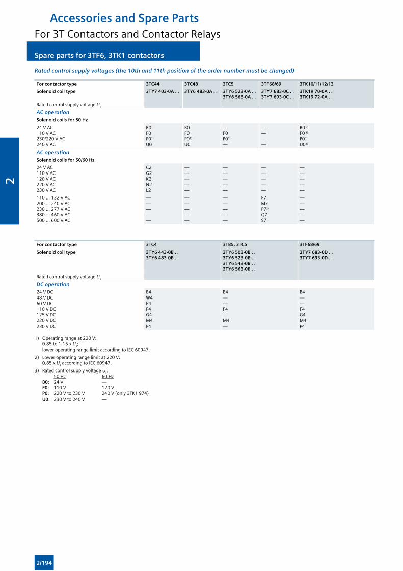
Spare parts for 3TF6, 3TK1 contactors Spare parts for 3TF6, 3TK1 contactors
Accessories and Spare PartsFor 3T Contactors and Contactor Relays
Rated control supply voltages (the 10th and 11th position of the order number must be changed)
For contactor type 3TC44 3TC48 3TC5 3TF68/69 3TK10/11/12/13
Solenoid coil type 3TY7 403-0A . . 3TY6 483-0A . . 3TY6 523-0A . .3TY6 566-0A . .
3TY7 683-0C . .3TY7 693-0C . .
3TK19 70-0A . .3TK19 72-0A . .
Rated control supply voltage Us
AC operation Solenoid coils for 50 Hz
24 V AC110 V AC230/220 V AC240 V AC
B0F0P01)
U0
B0F0P01)
U0
—F0P01)
—
————
B0 3)
F0 3)
P03)
U03)
AC operation Solenoid coils for 50/60 Hz
24 V AC110 V AC120 V AC220 V AC230 V AC
C2G2K2N2L2
—————
—————
—————
—————
110 ... 132 V AC200 ... 240 V AC230 ... 277 V AC380 ... 460 V AC500 ... 600 V AC
—————
—————
—————
F7M7P72)
Q7S7
—————
For contactor type 3TC4 3TB5, 3TC5 3TF68/69
Solenoid coil type 3TY6 443-0B . .3TY6 483-0B . .
3TY6 503-0B . .3TY6 523-0B . .3TY6 543-0B . .3TY6 563-0B . .
3TY7 683-0D . .3TY7 693-0D . .
Rated control supply voltage Us
DC operation24 V DC48 V DC60 V DC110 V DC125 V DC220 V DC230 V DC
B4W4E4F4G4M4P4
B4——F4—M4—
B4——F4G4M4P4
1) Operating range at 220 V: 0.85 to 1.15 x Us; lower operating range limit according to IEC 60947.
2) Lower operating range limit at 220 V: 0.85 x Us according to IEC 60947.
3) Rated control supply voltage Us: 50 Hz 60 Hz B0: 24 V — F0: 110 V 120 V P0: 220 V to 230 V 240 V (only 3TK1 974) U0: 230 V to 240 V —
2/194
2
33/2 Introduction
SIRIUS 3RW Soft Starters
3/3 General data
3RW30, 3RW40 for Standard Applications
3/6 3RW30
3/16 3RW40
3RW44 for High-Feature Applications
3/32 3RW44
SIRIUS 3RW Soft Starters
3
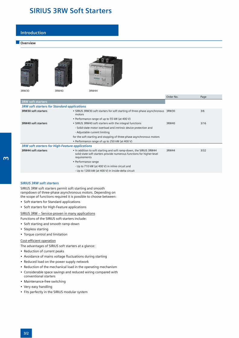
Introduction
Overview
3RW30 3RW40 3RW44
Order No. Page
3RW soft starters
3RW soft starters for Standard applications3RW30 soft starters •SIRIUS3RW30softstartersforsoftstartingofthree-phaseasynchronous
motors
•Performancerangeofupto55kW(at400V)
3RW30 3/6
3RW40 soft starters •SIRIUS3RW40softstarterswiththeintegralfunctions
- Solid-state motor overload and intrinsic device protection and
- Adjustable current limiting
forthesoftstartingandstoppingofthree-phaseasynchronousmotors
•Performancerangeofupto250kW(at400V)
3RW40 3/16
3RW soft starters for High-Feature applications3RW44 soft starters •Inadditiontosoftstartingandsoftramp-down,theSIRIUS3RW44
solid-state soft starters provide numerous functions for higher-level requirements
•Performancerange
-Upto710kW(at400V)ininlinecircuitand
-Upto1200kW(at400V)ininside-deltacircuit
3RW44 3/32
SIRIUS 3RW soft starters
SIRIUS3RWsoftstarterspermitsoftstartingandsmoothrampdownofthree-phaseasynchronousmotors.Dependingonthescopeoffunctionsrequireditispossibletochoosebetween:
• SoftstartersforStandardapplications
• SoftstartersforHigh-Featureapplications
SIRIUS3RW–Service-proveninmanyapplications
FunctionsoftheSIRIUSsoftstartersinclude:
• Softstartingandsmoothramp-down
• Steplessstarting
• Torquecontrolandlimitation
Cost-efficientoperation
TheadvantagesofSIRIUSsoftstartersataglance:
• Reductionofcurrentpeaks
• Avoidanceofmainsvoltagefluctuationsduringstarting
• Reducedloadonthepowersupplynetwork
• Reductionofthemechanicalloadintheoperatingmechanism
• Considerablespacesavingsandreducedwiringcomparedwithconventional starters
• Maintenance-freeswitching
• Veryeasyhandling
• FitsperfectlyintheSIRIUSmodularsystem
SIRIUS 3RW Soft Starters
3/2
3
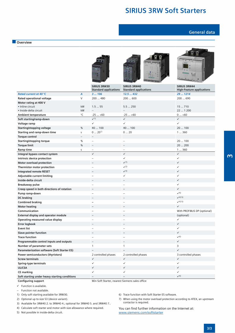
General data
Overview
SIRIUS 3RW30 Standard applications
SIRIUS 3RW40 Standard applications
SIRIUS 3RW44 High-Feature applications
Rated current at 40 °C A 3 ... 106 12.5 ... 432 29 ... 1214
Rated operational voltage V 200 ... 480 200 ... 600 200 ... 690
Motor rating at 400 V•Inlinecircuit•Inside-deltacircuit
kWkW
1.5...55--
5.5...250--
15...71022 ... 1 200
Ambient temperature °C -25...+60 -25...+60 0...+60
Soft starting/ramp-down 1)
Voltage ramp
Starting/stopping voltage % 40 ... 100 40 ... 100 20 ... 100
Starting and ramp-down time s 0 ... 201) 0 ... 20 1 ... 360
Torque control – –
Starting/stopping torque % – – 20 ... 100
Torque limit % – – 20 ... 200
Ramp time s – – 1 ... 360
Integral bypass contact system
Intrinsic device protection –
Motor overload protection – 7)
Thermistor motor protection – 2)
Integrated remote RESET – 3)
Adjustable current limiting –
Inside-delta circuit – –
Breakaway pulse – –
Creep speed in both directions of rotation – –
Pump ramp-down – – 4)
DC braking – – 4)5)
Combined braking – – 4)5)
Motor heating – –
Communication – – WithPROFIBUSDP(optional)
External display and operator module – – (optional)
Operating measured value display – –
Error logbook – –
Event list – –
Slave pointer function – –
Trace function – – 6)
Programmable control inputs and outputs – –
Number of parameter sets 1 1 3
Parameterization software (Soft Starter ES) – –
Power semiconductors (thyristors) 2 controlled phases 2 controlled phases 3 controlled phases
Screw terminals
Spring-type terminals
UL/CSA
CE marking
Soft starting under heavy starting conditions – – 4)
Configuring support Win-SoftStarter,nearestSiemenssalesoffice
Function is available.
-- Function not available.
1) Onlysoftstartingavailablefor3RW30.
2) OptionaluptosizeS3(devicevariant).
3) Availablefor3RW402.to3RW404.;optionalfor3RW405.and3RW407..
4) Calculatesoftstarterandmotorwithsizeallowancewhererequired.
5) Notpossibleininside-deltacircuit.
6) TracefunctionwithSoftStarterESsoftware.
7) WhenusingthemotoroverloadprotectionaccordingtoATEX,anupstreamcontactor is required.
YoucanfindfurtherinformationontheInternetat: www.siemens.com/softstarter
SIRIUS 3RW Soft Starters
3/3
3
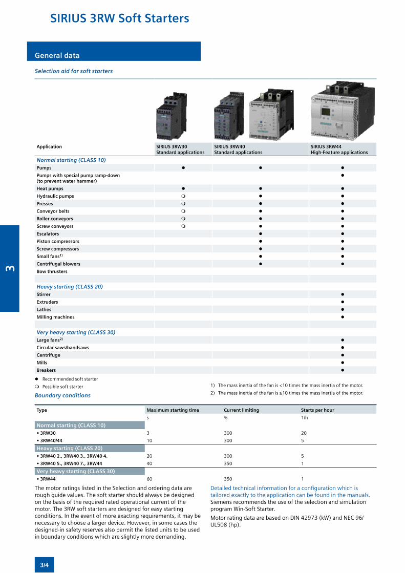
General data
Selection aid for soft starters
Application SIRIUS 3RW30 Standard applications
SIRIUS 3RW40 Standard applications
SIRIUS 3RW44 High-Feature applications
Normal starting (CLASS 10)Pumps
Pumps with special pump ramp-down (to prevent water hammer)
Heat pumps
Hydraulic pumps
Presses
Conveyor belts
Roller conveyors
Screw conveyors
Escalators
Piston compressors
Screw compressors
Small fans1)
Centrifugal blowers
Bow thrusters
Heavy starting (CLASS 20)Stirrer
Extruders
Lathes
Milling machines
Very heavy starting (CLASS 30)Large fans2)
Circular saws/bandsaws
Centrifuge
Mills
Breakers
Recommended soft starter
Possible soft starter 1) Themassinertiaofthefanis<10timesthemassinertiaofthemotor.
2) Themassinertiaofthefanis≥10timesthemassinertiaofthemotor.Boundary conditions
Type Maximum starting time Current limiting Starts per hour
s % 1/h
Normal starting (CLASS 10)• 3RW30 3 300 20
• 3RW40/44 10 300 5
Heavy starting (CLASS 20)• 3RW40 2., 3RW40 3., 3RW40 4. 20 300 5
• 3RW40 5., 3RW40 7., 3RW44 40 350 1
Very heavy starting (CLASS 30)• 3RW44 60 350 1
ThemotorratingslistedintheSelectionandorderingdataareroughguidevalues.Thesoftstartershouldalwaysbedesignedon the basis of the required rated operational current of the motor.The3RWsoftstartersaredesignedforeasystartingconditions. Intheeventofmoreexactingrequirements,itmaybenecessarytochoosealargerdevice.However,insomecasesthedesigned-insafetyreservesalsopermitthelistedunitstobeusedinboundaryconditionswhichareslightlymoredemanding.
Detailedtechnicalinformationforaconfigurationwhichistailoredexactlytotheapplicationcanbefoundinthemanuals. Siemens recommends the use of the selection and simulation program Win-Soft Starter.
MotorratingdataarebasedonDIN42973(kW)andNEC96/UL508(hp).
SIRIUS 3RW Soft Starters
3/4
3
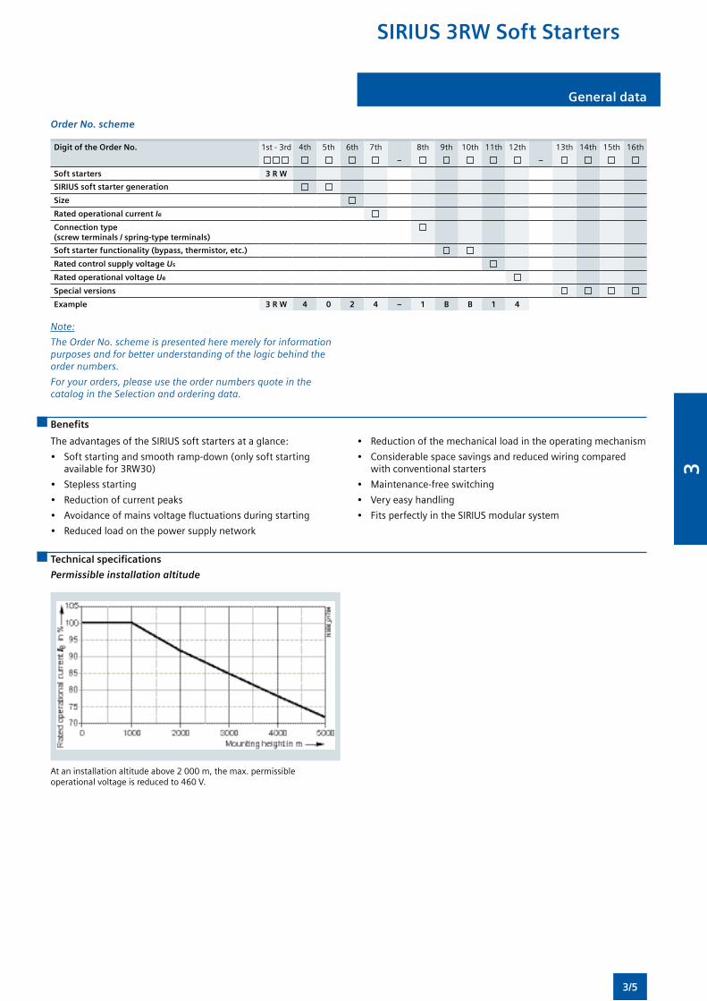
General data
Order No. scheme
Digit of the Order No. 1st - 3rd 4th 5th 6th 7th 8th 9th 10th 11th 12th 13th 14th 15th 16th
– –
Soft starters 3 R W
SIRIUS soft starter generation
Size
Rated operational current Ie
Connection type (screw terminals / spring-type terminals)
Soft starter functionality (bypass, thermistor, etc.)
Rated control supply voltage Us
Rated operational voltage Ue
Special versions
Example 3 R W 4 0 2 4 – 1 B B 1 4
Note:
The Order No. scheme is presented here merely for information purposes and for better understanding of the logic behind the order numbers.
For your orders, please use the order numbers quote in the catalog in the Selection and ordering data.
Benefits
TheadvantagesoftheSIRIUSsoftstartersataglance:
• Softstartingandsmoothramp-down(onlysoftstartingavailablefor3RW30)
• Steplessstarting
• Reductionofcurrentpeaks
• Avoidanceofmainsvoltagefluctuationsduringstarting
• Reducedloadonthepowersupplynetwork
• Reductionofthemechanicalloadintheoperatingmechanism
• Considerablespacesavingsandreducedwiringcomparedwithconventionalstarters
• Maintenance-freeswitching
• Veryeasyhandling
• FitsperfectlyintheSIRIUSmodularsystem
Technical specifications
Permissible installation altitude
Ataninstallationaltitudeabove2000m,themax.permissibleoperationalvoltageisreducedto460V.
SIRIUS 3RW Soft Starters
3/5
3
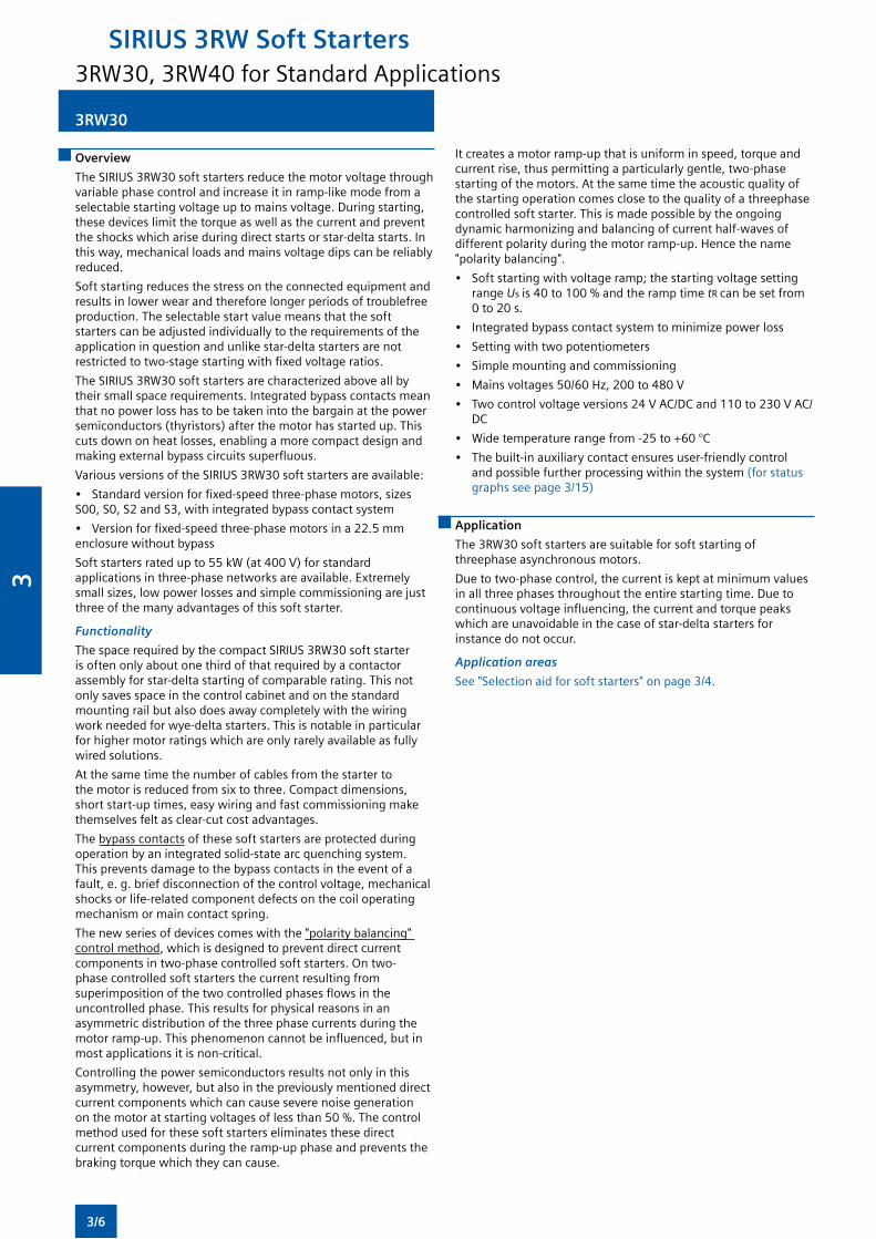
3RW30
Overview
TheSIRIUS3RW30softstartersreducethemotorvoltagethroughvariablephasecontrolandincreaseitinramp-likemodefromaselectablestartingvoltageuptomainsvoltage.Duringstarting,thesedeviceslimitthetorqueaswellasthecurrentandpreventtheshockswhichariseduringdirectstartsorstar-deltastarts.Inthisway,mechanicalloadsandmainsvoltagedipscanbereliablyreduced.
Soft starting reduces the stress on the connected equipment and resultsinlowerwearandthereforelongerperiodsoftroublefreeproduction.Theselectablestartvaluemeansthatthesoftstarterscanbeadjustedindividuallytotherequirementsoftheapplicationinquestionandunlikestar-deltastartersarenotrestrictedtotwo-stagestartingwithfixedvoltageratios.
TheSIRIUS3RW30softstartersarecharacterizedaboveallbytheirsmallspacerequirements.Integratedbypasscontactsmeanthatnopowerlosshastobetakenintothebargainatthepowersemiconductors(thyristors)afterthemotorhasstartedup.Thiscutsdownonheatlosses,enablingamorecompactdesignandmakingexternalbypasscircuitssuperfluous.
VariousversionsoftheSIRIUS3RW30softstartersareavailable:
• Standardversionforfixed-speedthree-phasemotors,sizesS00,S0,S2andS3,withintegratedbypasscontactsystem
• Versionforfixed-speedthree-phasemotorsina22.5mmenclosurewithoutbypass
Softstartersratedupto55kW(at400V)forstandardapplicationsinthree-phasenetworksareavailable.Extremelysmallsizes,lowpowerlossesandsimplecommissioningarejustthreeofthemanyadvantagesofthissoftstarter.
Functionality
ThespacerequiredbythecompactSIRIUS3RW30softstarterisoftenonlyaboutonethirdofthatrequiredbyacontactorassemblyforstar-deltastartingofcomparablerating.Thisnotonlysavesspaceinthecontrolcabinetandonthestandardmountingrailbutalsodoesawaycompletelywiththewiringworkneededforwye-deltastarters.Thisisnotableinparticularforhighermotorratingswhichareonlyrarelyavailableasfullywiredsolutions.
At the same time the number of cables from the starter to themotorisreducedfromsixtothree.Compactdimensions,shortstart-uptimes,easywiringandfastcommissioningmakethemselves felt as clear-cut cost advantages.
Thebypasscontacts of these soft starters are protected during operationbyanintegratedsolid-statearcquenchingsystem.Thispreventsdamagetothebypasscontactsintheeventofafault, e. g. brief disconnection of the control voltage, mechanical shocksorlife-relatedcomponentdefectsonthecoiloperatingmechanism or main contact spring.
Thenewseriesofdevicescomeswiththe"polaritybalancing"control method,whichisdesignedtopreventdirectcurrentcomponentsintwo-phasecontrolledsoftstarters.Ontwo-phase controlled soft starters the current resulting from superimpositionofthetwocontrolledphasesflowsintheuncontrolledphase.Thisresultsforphysicalreasonsinanasymmetricdistributionofthethreephasecurrentsduringthemotorramp-up.Thisphenomenoncannotbeinfluenced,butinmost applications it is non-critical.
Controllingthepowersemiconductorsresultsnotonlyinthisasymmetry,however,butalsointhepreviouslymentioneddirectcurrentcomponentswhichcancauseseverenoisegenerationonthemotoratstartingvoltagesoflessthan50%.Thecontrolmethod used for these soft starters eliminates these direct current components during the ramp-up phase and prevents the brakingtorquewhichtheycancause.
Itcreatesamotorramp-upthatisuniforminspeed,torqueandcurrentrise,thuspermittingaparticularlygentle,two-phasestartingofthemotors.Atthesametimetheacousticqualityofthestartingoperationcomesclosetothequalityofathreephasecontrolledsoftstarter.Thisismadepossiblebytheongoingdynamicharmonizingandbalancingofcurrenthalf-wavesofdifferentpolarityduringthemotorramp-up.Hencethename"polaritybalancing".
• Softstartingwithvoltageramp;thestartingvoltagesettingrange Us is 40 to 100 % and the ramp time tR can be set from 0 to 20 s.
• Integratedbypasscontactsystemtominimizepowerloss
• Settingwithtwopotentiometers
• Simplemountingandcommissioning
• Mainsvoltages50/60Hz,200to480V
• Twocontrolvoltageversions24VAC/DCand110to230VAC/DC
• Widetemperaturerangefrom-25to+60°C
• Thebuilt-inauxiliarycontactensuresuser-friendlycontrolandpossiblefurtherprocessingwithinthesystem(forstatusgraphsseepage3/15)
Application
The3RW30softstartersaresuitableforsoftstartingofthreephaseasynchronousmotors.
Duetotwo-phasecontrol,thecurrentiskeptatminimumvaluesinallthreephasesthroughouttheentirestartingtime.Duetocontinuousvoltageinfluencing,thecurrentandtorquepeakswhichareunavoidableinthecaseofstar-deltastartersforinstance do not occur.
Application areas
See "Selection aid for soft starters" on page 3/4.
3RW30, 3RW40 for Standard Applications
SIRIUS 3RW Soft Starters
3/6
3
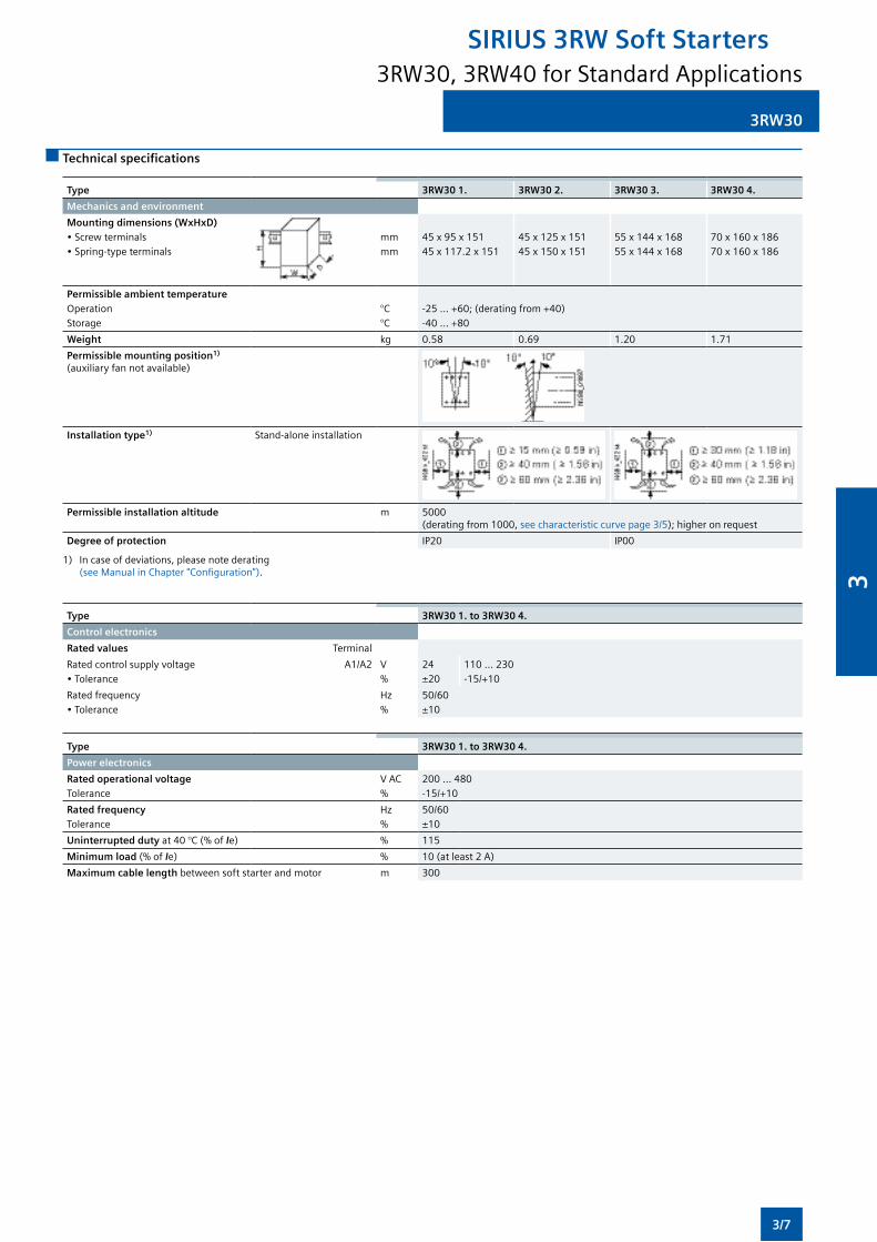
3RW30
Technical specifications
Type 3RW30 1. 3RW30 2. 3RW30 3. 3RW30 4.
Mechanics and environment
Mounting dimensions (WxHxD)•Screwterminals•Spring-typeterminals
mmmm
45x95x15145x117.2x151
45x125x15145x150x151
55x144x16855x144x168
70x160x18670x160x186
Permissible ambient temperatureOperationStorage
°C°C
-25...+60;(deratingfrom+40)-40...+80
Weight kg 0.58 0.69 1.20 1.71
Permissible mounting position1) (auxiliaryfannotavailable)
Installation type1) Stand-alone installation
Permissible installation altitude m 5000 (deratingfrom1000,seecharacteristiccurvepage3/5);higheronrequest
Degree of protection IP20 IP00
1) Incaseofdeviations,pleasenotederating (seeManualinChapter"Configuration").
Type 3RW30 1. to 3RW30 4.
Control electronics
Rated values Terminal
Ratedcontrolsupplyvoltage•Tolerance
A1/A2 V%
24±20
110 ... 230-15/+10
Ratedfrequency•Tolerance
Hz%
50/60±10
Type 3RW30 1. to 3RW30 4.
Power electronics
Rated operational voltage Tolerance
VAC%
200 ... 480-15/+10
Rated frequency Tolerance
Hz%
50/60±10
Uninterrupted duty at40°C(%ofIe) % 115
Minimum load (%ofIe) % 10(atleast2A)
Maximum cable length betweensoftstarterandmotor m 300
3RW30, 3RW40 for Standard Applications
SIRIUS 3RW Soft Starters
3/7
3
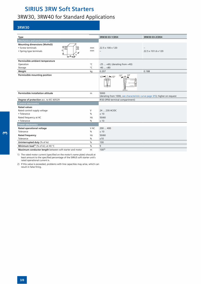
3RW30
Type 3RW30 03-1CB54 3RW30 03-2CB54
Mechanics and environment
Mounting dimensions (WxHxD)•Screwterminals•Spring-typeterminals
mm mm
22.5x100x120–
–22.5x101.6x120
Permissible ambient temperatureOperationStorage
°C°C
-25...+60;(deratingfrom+40)-40...+80
Weight kg 0.207 0.188
Permissible mounting position
Permissible installation altitude m 5000 (deratingfrom1000,seecharacteristiccurvepage3/5);higheronrequest
Degree of protection acc.toIEC60529 IP20(IP00terminalcompartment)
Control electronics
Rated valuesRatedcontrolsupplyvoltage•Tolerance
V%
24...230AC/DC± 10
RatedfrequencyatAC•Tolerance
Hz%
50/60± 10
Power electronics
Rated operational voltage Tolerance
VAC%
200 ... 400± 10
Rated frequency Tolerance
Hz%
50/60±10
Uninterrupted duty (%ofIe) % 100
Minimum load1) (%ofIe);at40°C % 9
Maximum conductor length betweensoftstarterandmotor m 1002)
1) Theratedmotorcurrent(specifiedonthemotor’snameplate)shouldatleastamounttothespecifiedpercentageoftheSIRIUSsoftstarterunit’srated operational current Ie.
2) Ifthisvalueisexceeded,problemswithlinecapacitiesmayarise,whichcanresultinfalsefiring.
3RW30, 3RW40 for Standard Applications
SIRIUS 3RW Soft Starters
3/8
3
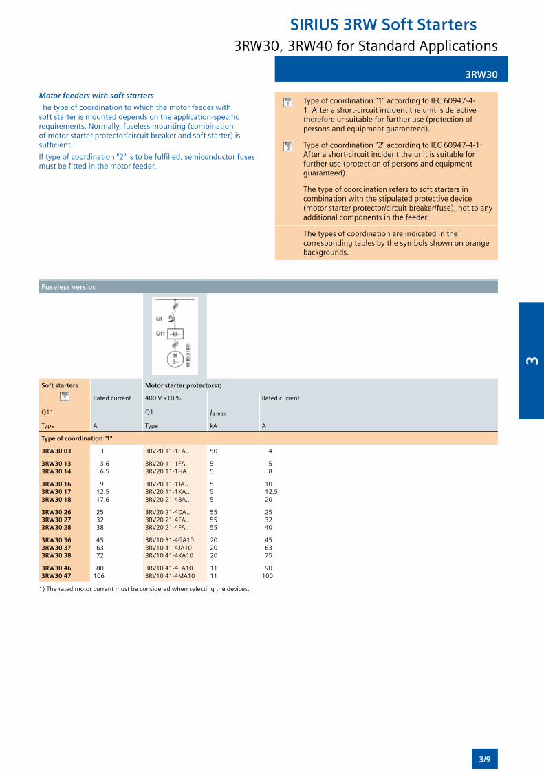
3RW30
Motor feeders with soft starters
Thetypeofcoordinationtowhichthemotorfeederwithsoftstarterismounteddependsontheapplication-specificrequirements.Normally,fuselessmounting(combinationofmotorstarterprotector/circuitbreakerandsoftstarter)issufficient.
Iftypeofcoordination"2"istobefulfilled,semiconductorfusesmustbefittedinthemotorfeeder.
Typeofcoordination“1”accordingtoIEC60947-4-1:Afterashort-circuitincidenttheunitisdefectivethereforeunsuitableforfurtheruse(protectionofpersonsandequipmentguaranteed).
Typeofcoordination“2”accordingtoIEC60947-4-1:After a short-circuit incident the unit is suitable for furtheruse(protectionofpersonsandequipmentguaranteed).
Thetypeofcoordinationreferstosoftstartersincombinationwiththestipulatedprotectivedevice(motorstarterprotector/circuitbreaker/fuse),nottoanyadditional components in the feeder.
Thetypesofcoordinationareindicatedinthecorrespondingtablesbythesymbolsshownonorangebackgrounds.
Fuseless version
Soft starters Motor starter protectors1)
Rated current 400V+10% Rated current
Q11 Q1 Iqmax
Type A Type kA A
Type of coordination "1"
3RW30 03 3 3RV2011-1EA.. 50 4
3RW30 13 3RW30 14
3.6 6.5
3RV2011-1FA..3RV2011-1HA..
55
58
3RW30 16 3RW30 17 3RW30 18
9 12.517.6
3RV2011-1JA..3RV2011-1KA..3RV2021-4BA..
555
10 12.5 20
3RW30 26 3RW30 27 3RW30 28
2532 38
3RV2021-4DA..3RV2021-4EA..3RV2021-4FA..
555555
2532 40
3RW30 36 3RW30 37 3RW30 38
4563 72
3RV1031-4GA103RV1041-4JA103RV1041-4KA10
20 20 20
45 63 75
3RW30 46 3RW30 47
80 106
3RV1041-4LA103RV1041-4MA10
11 11
90 100
1)Theratedmotorcurrentmustbeconsideredwhenselectingthedevices.
3RW30, 3RW40 for Standard Applications
SIRIUS 3RW Soft Starters
3/9
3
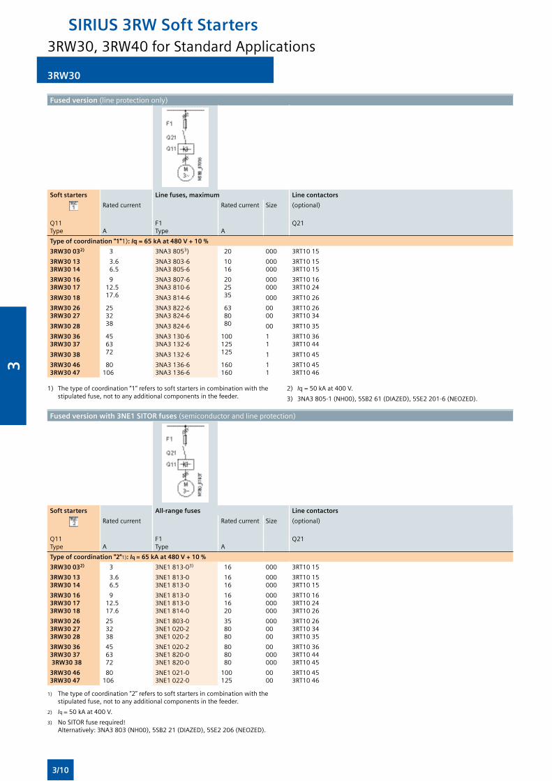
3RW30
Fused version (lineprotectiononly)
Soft starters Line fuses, maximum Line contactors
Rated current Rated current Size (optional)
Q11Type A
F1Type A
Q21
Type of coordination "1"1): Iq = 65 kA at 480 V + 10 %
3RW30 032) 3 3NA38053) 20 000 3RT1015
3RW30 13 3RW30 14
3.6 6.5
3NA3 803-6 3NA3805-6
10 16
000 000
3RT10153RT1015
3RW30 16 3RW30 17
3RW30 18
9 12.517.6
3NA3807-63NA3 810-6
3NA3 814-6
20 2535
000 000
000
3RT10163RT1024
3RT1026
3RW30 26 3RW30 27
3RW30 28
253238
3NA3 822-6 3NA3 824-6
3NA3 824-6
63 8080
00 00
00
3RT10263RT1034
3RT1035
3RW30 36 3RW30 37
3RW30 38
456372
3NA3 130-6 3NA3 132-6
3NA3 132-6
100 125125
1 1
1
3RT10363RT1044
3RT1045
3RW30 46 3RW30 47
80 106
3NA3 136-6 3NA3 136-6
160 160
1 1
3RT10453RT1046
Fused version with 3NE1 SITOR fuses (semiconductorandlineprotection)
Soft starters All-range fuses Line contactors
Rated current Rated current Size (optional)
Q11Type A
F1Type A
Q21
Type of coordination "2"1): Iq = 65 kA at 480 V + 10 %
3RW30 032) 3 3NE1813-03) 16 000 3RT1015
3RW30 13 3RW30 14
3.6 6.5
3NE1813-03NE1813-0
16 16
000 000
3RT10153RT1015
3RW30 16 3RW30 173RW30 18
9 12.517.6
3NE1813-03NE1813-03NE1814-0
16 16 20
000 000000
3RT10163RT10243RT1026
3RW30 26 3RW30 273RW30 28
2532 38
3NE1803-03NE1020-23NE1020-2
3580 80
000 0000
3RT10263RT10343RT1035
3RW30 363RW30 37 3RW30 38
4563 72
3NE1020-23NE1820-03NE1820-0
80 80 80
00 000000
3RT10363RT10443RT1045
3RW30 46 3RW30 47
80 106
3NE1021-03NE1022-0
100 125
00 00
3RT10453RT1046
1) Thetypeofcoordination“2”referstosoftstartersincombinationwiththestipulatedfuse,nottoanyadditionalcomponentsinthefeeder.
2) Iq =50kAat400V.
3) NoSITORfuserequired! Alternatively:3NA3803(NH00),5SB221(DIAZED),5SE2206(NEOZED).
1) Thetypeofcoordination“1”referstosoftstartersincombinationwiththestipulatedfuse,nottoanyadditionalcomponentsinthefeeder.
2) Iq=50kAat400V.
3) 3NA3805-1(NH00),5SB261(DIAZED),5SE2201-6(NEOZED).
3RW30, 3RW40 for Standard Applications
SIRIUS 3RW Soft Starters
3/10
3
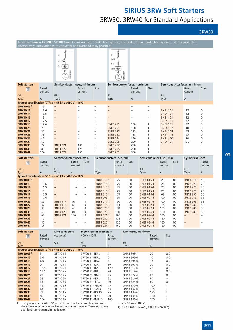
3RW30
Fused version with 3NE3 SITOR fuses (semiconductorprotectionbyfuse,lineandoverloadprotectionbymotorstarterprotector;alternatively,installationwithcontactorandoverloadrelaypossible)
Soft starters Semiconductor fuses, minimum Semiconductor fuses, maximum Semiconductor fuses, minimumRated current
Rated current
Size Rated current
Size Rated current
Size
Q11 Type A
F3 Type A
F3 Type A
F3 Type A
Type of coordination "2"1): Iq = 65 kA at 480 V + 10 %3RW30 032) 3 – – – – – –3RW30 13 3RW30 14
3.6 6.5
––
––
––
––
––
––
3NE41013NE4101
32 32
00
3RW30 16 3RW30 173RW30 18
9 12.517.6
–––
–––
–––
––3NE3221
––100
––1
3NE41013NE41013NE4101
323232
000
3RW30 26 3RW30 273RW30 28
253238
–––
–––
–––
3NE32213NE32223NE3222
100 125125
1 11
3NE41023NE41183NE4118
40 6363
000
3RW30 36 3RW30 373RW30 38
456372
––3NE3221
––100
––1
3NE32243NE32253NE3227
160 200250
1 11
3NE41203NE4121–
80 100–
00–
3RW30 46 3RW30 47
80 106
3NE32223NE3224
125160
1 1
3NE32253NE3231
200 350
1 1
––
––
––
Soft starters Semiconductor fuses, max. Semiconductor fuses, min. Semiconductor fuses, max. Cylindrical fusesRated current
Rated current
Size Rated current
Size Rated current
Size Rated current
Q11 Type A
F3 Type A
F3 Type A
F3 Type A
F3 Type A
Type of coordination "2"1): Iq = 65 kA at 480 V + 10 %3RW30 032) 3 – – – 3NE8015-1 25 00 3NE8015-1 25 00 3NC1 010 103RW30 13 3RW30 14
3.6 6.5
––
––
––
3NE8015-13NE8015-1
2525
00 00
3NE8015-13NE8015-1
2525
00 00
3NC2 220 3NC2 220
2020
3RW30 16 3RW30 173RW30 18
9 12.517.6
–––
–––
–––
3NE8015-13NE8015-13NE8003-1
252535
00 0000
3NE8015-13NE8018-13NE8021-1
2563
100
00 0000
3NC2 220 3NC22503NC2 263
205063
3RW30 26 3RW30 273RW30 28
253238
3NE41173NE41183NE4118
506363
0 00
3NE8017-13NE8018-13NE8020-1
506380
00 0000
3NE8021-13NE8022-13NE8022-1
100 125125
00 0000
3NC2 263 3NC2 2803NC2 280
638080
3RW30 36 3RW30 373RW30 38
456372
3NE41203NE4121–
80 100
–
0 0–
3NE8020-13NE8021-13NE8022-1
80 100125
00 0000
3NE8024-13NE8024-13NE8024-1
160 160160
00 0000
3NC2 280 ––
80––
3RW30 46 3RW30 47
80 106
––
––
––
3NE8022-13NE8024-1
125160
00 00
3NE8024-13NE8024-1
160 160
00 00
––
––
Soft starters Line contactors Motor starter protectors Line fuses, maximumRated current
(optional) 400V+10% Rated current
Rated current
Size
Q11 Type A
Q21 Q1 Type A
F1 Type A
Type of coordination "2"1): Iq = 65 kA at 480 V + 10 %3RW30 032) 3 3RT1015 3RV2011-1EA.. 4 3NA38053) 20 0003RW30 13 3RW30 14
3.6 6.5
3RT10153RT1015
3RV2011-1FA..3RV2011-1HA..
58
3NA3 803-6 3NA3805-6
10 16
000000
3RW30 16 3RW30 173RW30 18
9 12.517.6
3RT10163RT10243RT1026
3RV2011-1JA..3RV2011-1KA..3RV2021-4BA..
10 12.520
3NA3807-63NA3 810-63NA3 814-6
20 2535
000000000
3RW30 26 3RW30 273RW30 28
253238
3RT10263RT10343RT1035
3RV2021-4DA..3RV2021-4EA..3RV2021-4FA..
253240
3NA3 822-6 3NA3 824-63NA3 824-6
63 8080
000000
3RW30 36 3RW30 373RW30 38
456372
3RT10363RT10443RT1045
3RV1031-4GA103RV1041-4JA103RV1041-4KA10
456375
3NA3 130-6 3NA3 132-63NA3 132-6
100 125125
111
3RW30 46 3RW30 47
80 106
3RT10453RT1046
3RV1041-4LA103RV1041-4MA10
90 100
3NA3 136-6 3NA3 136-6
160 160
11
1) Thetypeofcoordination“2”referstosoftstartersincombinationwiththestipulatedprotectivedevice(motorstarterprotector/fuse),nottoanyadditional components in the feeder.
2) Iq =50kAat400V.
3) 3NA3805-1(NH00),5SB261(DIAZED).
3RW30, 3RW40 for Standard Applications
SIRIUS 3RW Soft Starters
3/11
3
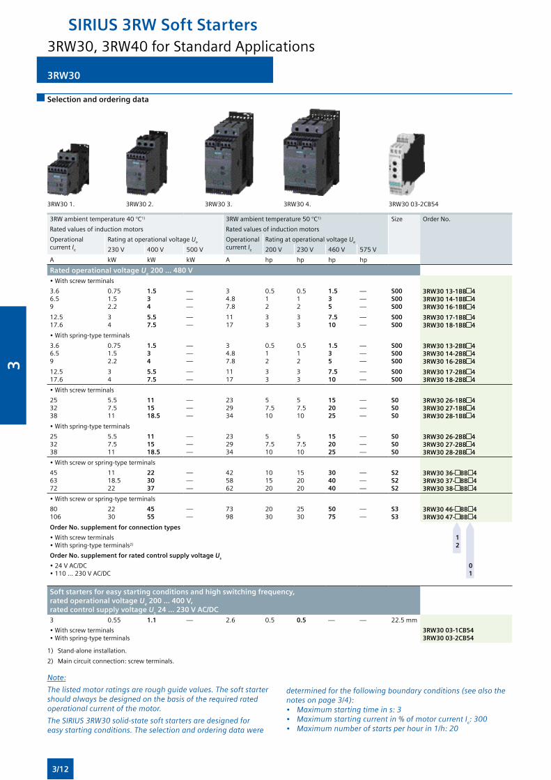
3RW30
Selection and ordering data
3RW301. 3RW302. 3RW303. 3RW304. 3RW3003-2CB54
3RW ambient temperature 40 °C1) 3RWambienttemperature50°C1) Size Order No.
Rated values of induction motors Rated values of induction motors
Operational current Ie
Rating at operational voltage Ue Operational current Ie
Rating at operational voltage Ue
230V 400V 500V 200V 230V 460V 575V
A kW kW kW A hp hp hp hp
Rated operational voltage Ue 200 ... 480 V•Withscrewterminals
3.66.59
0.751.52.2
1.534
———
34.87.8
0.512
0.512
1.535
———
S00 S00 S00
3RW30 13-1BB 43RW30 14-1BB 43RW30 16-1BB 4
12.517.6
34
5.57.5
——
1117
33
33
7.510
——
S00 S00
3RW30 17-1BB 43RW30 18-1BB 4
•Withspring-typeterminals
3.66.59
0.751.52.2
1.534
———
34.87.8
0.512
0.512
1.535
———
S00 S00 S00
3RW30 13-2BB 43RW30 14-2BB 43RW30 16-2BB 4
12.517.6
34
5.57.5
——
1117
33
33
7.510
——
S00 S00
3RW30 17-2BB 43RW30 18-2BB 4
•Withscrewterminals
253238
5.57.511
111518.5
———
232934
57.510
57.510
152025
———
S0 S0 S0
3RW30 26-1BB 43RW30 27-1BB 43RW30 28-1BB 4
•Withspring-typeterminals
253238
5.57.511
111518.5
———
232934
57.510
57.510
152025
———
S0 S0 S0
3RW30 26-2BB 43RW30 27-2BB 43RW30 28-2BB 4
•Withscreworspring-typeterminals
456372
1118.522
223037
———
425862
101520
152020
304040
———
S2 S2 S2
3RW30 36- BB 43RW30 37- BB 43RW30 38- BB 4
•Withscreworspring-typeterminals
80106
2230
4555
——
7398
2030
2530
5075
——
S3 S3
3RW30 46- BB 43RW30 47- BB 4
Order No. supplement for connection types
•Withscrewterminals•Withspring-typeterminals2)
1 2
Order No. supplement for rated control supply voltage Us
•24VAC/DC•110...230VAC/DC
0 1
Soft starters for easy starting conditions and high switching frequency, rated operational voltage Ue 200 ... 400 V, rated control supply voltage Us 24 ... 230 V AC/DC3 0.55 1.1 — 2.6 0.5 0.5 — — 22.5mm
•Withscrewterminals•Withspring-typeterminals
3RW30 03-1CB543RW30 03-2CB54
1) Stand-aloneinstallation.
2) Maincircuitconnection:screwterminals.
Note:
The listed motor ratings are rough guide values. The soft starter should always be designed on the basis of the required rated operational current of the motor.
The SIRIUS 3RW30 solid-state soft starters are designed for easy starting conditions. The selection and ordering data were
determined for the following boundary conditions (see also the notes on page 3/4):• Maximum starting time in s: 3• Maximum starting current in % of motor current Ie: 300• Maximum number of starts per hour in 1/h: 20
3RW30, 3RW40 for Standard Applications
SIRIUS 3RW Soft Starters
3/12
3
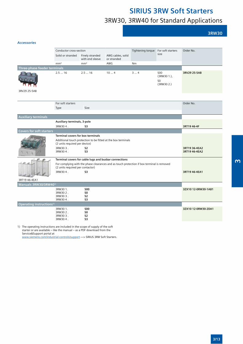
3RW30
Accessories
Conductor cross-section Tighteningtorque For soft starters size
Order No.
Solid or stranded Finelystrandedwithendsleeve
AWG cables, solid or stranded
mm² mm² AWG Nm
Three-phase feeder terminals
3RV2925-5AB
2.5...16 2.5...16 10 ... 4 3 ... 4 S00 (3RW301.),
S0 (3RW302.)
3RV29 25-5AB
For soft starters Order No.
Type Size
Auxiliary terminalsAuxiliary terminals, 3-pole
3RW30 4 . S3 3RT19 46-4F
Covers for soft startersTerminal covers for box terminals
Additionaltouchprotectiontobefittedattheboxterminals (2unitsrequiredperdevice)
3RW30 3 . 3RW30 4 .
S2 S3
3RT19 36-4EA23RT19 46-4EA2
3RT1946-4EA1
Terminal covers for cable lugs and busbar connections
Forcomplyingwiththephaseclearancesandastouchprotectionifboxterminalisremoved (2unitsrequiredpercontactor)
3RW30 4 . S3 3RT19 46-4EA1
Manuals 3RW30/3RW401) 3RW30 1. 3RW30 2 . 3RW30 3 . 3RW30 4 .
S00S0S2S3
3ZX10 12-0RW30-1AB1
Operating instructions1) 3RW30 1. 3RW30 2 . 3RW30 3 . 3RW30 4 .
S00S0S2S3
3ZX10 12-0RW30-2DA1
1) Theoperatinginstructionsareincludedinthescopeofsupplyofthesoftstarterorareavailable–likethemanual–asaPDFdownloadfromtheService&Support portal at www.siemens.com/industrial-controls/support—>SIRIUS3RWSoftStarters.
3RW30, 3RW40 for Standard Applications
SIRIUS 3RW Soft Starters
3/13
3
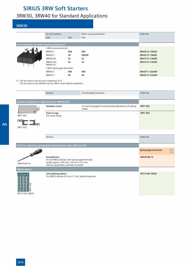
3RW30
For soft starters Motorstarterprotectors Order No.
Type Size Size
Link modules to motor starter protectors1) •Withscrewterminals
3RW30 1. S00 S00 3RA29 21-1BA00
3RW30 2. S0 S00/S0 3RA29 21-1BA00
3RW30 36. S2 S2 3RA19 31-1AA00
3RW30 46., 3RW3047.
S3 S3 3RA19 41-1AA00
•Withspring-typeterminals
3RW30 1. S00 S00 3RA29 11-2GA00
3RW30 2. S0 S0 3RA29 21-2GA00
1) CanbeusedinsizeS0uptomaximum32A. CanbeusedinsizeS00/S0onlyfor3RV2motorstarterprotectors.
Version FunctionalityFunctions Order No.
Covers and push-in lugs (only for 3RW30 03)
3RP1 902
3RP1 903
Sealable covers Forsecuringagainstunauthorizedadjustmentofsettingknobs
3RP1 902
Push-in lugs Forscrewfixing
3RP1 903
Version Order No.
Tool for opening spring-type terminals for sizes S00 and S0
3RA29 08-1A
Spring-type terminals
ScrewdriversForallSIRIUSdeviceswithspring-typeterminals lengthapprox.200mm,3.0mmx0.5mm, titaniumgray/black,partiallyinsulated
3RA29 08-1A
Blank labels
3RT1900-1SB20
Unit labeling plates1)
ForSIRIUSdevices20mmx7mm,pastelturquoise3RT19 00-1SB20
3RW30, 3RW40 for Standard Applications
SIRIUS 3RW Soft Starters
3/14
3
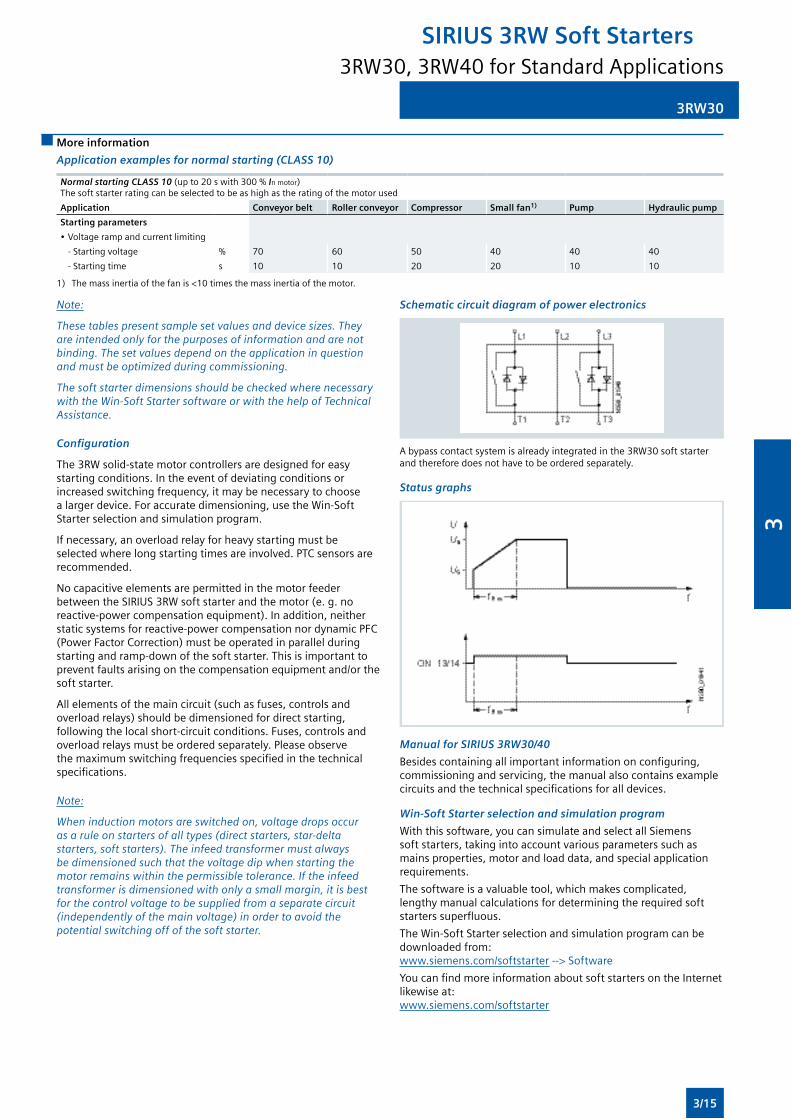
3RW30
More information
Application examples for normal starting (CLASS 10)
Normal starting CLASS 10 (upto20swith300%In motor) Thesoftstarterratingcanbeselectedtobeashighastheratingofthemotorused
Application Conveyor belt Roller conveyor Compressor Small fan1) Pump Hydraulic pump
Starting parameters
•Voltagerampandcurrentlimiting
- Starting voltage % 70 60 50 40 40 40
- Starting time s 10 10 20 20 10 10
1) Themassinertiaofthefanis<10timesthemassinertiaofthemotor.
Note:
These tables present sample set values and device sizes. They are intended only for the purposes of information and are not binding. The set values depend on the application in question and must be optimized during commissioning.
The soft starter dimensions should be checked where necessary with the Win-Soft Starter software or with the help of Technical Assistance.
Configuration
The3RWsolid-statemotorcontrollersaredesignedforeasystartingconditions.Intheeventofdeviatingconditionsorincreasedswitchingfrequency,itmaybenecessarytochoosea larger device. For accurate dimensioning, use the Win-Soft Starter selection and simulation program.
Ifnecessary,anoverloadrelayforheavystartingmustbeselectedwherelongstartingtimesareinvolved.PTCsensorsarerecommended.
No capacitive elements are permitted in the motor feeder betweentheSIRIUS3RWsoftstarterandthemotor(e.g.noreactive-powercompensationequipment).Inaddition,neitherstaticsystemsforreactive-powercompensationnordynamicPFC(PowerFactorCorrection)mustbeoperatedinparallelduringstartingandramp-downofthesoftstarter.Thisisimportanttoprevent faults arising on the compensation equipment and/or the soft starter.
Allelementsofthemaincircuit(suchasfuses,controlsandoverloadrelays)shouldbedimensionedfordirectstarting,followingthelocalshort-circuitconditions.Fuses,controlsandoverloadrelaysmustbeorderedseparately.Pleaseobservethemaximumswitchingfrequenciesspecifiedinthetechnicalspecifications.
Note:
When induction motors are switched on, voltage drops occur as a rule on starters of all types (direct starters, star-delta starters, soft starters). The infeed transformer must always be dimensioned such that the voltage dip when starting the motor remains within the permissible tolerance. If the infeed transformer is dimensioned with only a small margin, it is best for the control voltage to be supplied from a separate circuit (independently of the main voltage) in order to avoid the potential switching off of the soft starter.
Schematic circuit diagram of power electronics
Abypasscontactsystemisalreadyintegratedinthe3RW30softstarterandthereforedoesnothavetobeorderedseparately.
Status graphs
Manual for SIRIUS 3RW30/40
Besidescontainingallimportantinformationonconfiguring,commissioningandservicing,themanualalsocontainsexamplecircuitsandthetechnicalspecificationsforalldevices.
Win-Soft Starter selection and simulation program
Withthissoftware,youcansimulateandselectallSiemenssoftstarters,takingintoaccountvariousparameterssuchasmains properties, motor and load data, and special application requirements.
Thesoftwareisavaluabletool,whichmakescomplicated,lengthymanualcalculationsfordeterminingtherequiredsoftstarterssuperfluous.
TheWin-SoftStarterselectionandsimulationprogramcanbedownloadedfrom: www.siemens.com/softstarter-->Software
YoucanfindmoreinformationaboutsoftstartersontheInternetlikewiseat: www.siemens.com/softstarter
3RW30, 3RW40 for Standard Applications
SIRIUS 3RW Soft Starters
3/15
3
3RW40
Overview
SIRIUS3RW40softstartershaveallthesameadvantagesasthe3RW30 soft starters.
TheSIRIUS3RW40softstartersarecharacterizedaboveallbytheirsmallspacerequirements.Integratedbypasscontactsmeanthatnopowerlosshastobetakenintothebargainatthepowersemiconductors(thyristors)afterthemotorhasstartedup.Thiscutsdownonheatlosses,enablingamorecompactdesignandmakingexternalbypasscircuitssuperfluous.
Atthesametimethissoftstartercomeswithadditionalintegrated functions such as adjustable current limiting, motor overload and intrinsic device protection, and optional thermistor motorprotection.Thehigherthemotorrating,themoreimportantthesefunctionsbecausetheymakeitunnecessaryto purchase and install protection equipment such as overload relays.
Internalintrinsicdeviceprotectionpreventsthethermaloverloadingofthethyristorsandthepowersectiondefectsthiscancause.Asanoptionthethyristorscanalsobeprotectedbysemiconductor fuses from short-circuiting.
Thankstointegratedstatusmonitoringandfaultmonitoring,thiscompactsoftstarteroffersmanydifferentdiagnosticsoptions.UptofourLEDsandrelayoutputspermitdifferentiatedmonitoringanddiagnosticsoftheoperatingmechanismbyindicatingtheoperatingstateaswellasforexamplemainsorphase failure, missing load, non-permissible tripping time/class setting, thermal overloading or device faults.
Softstartersratedupto250kW(at400V)forstandardapplicationsinthree-phasenetworksareavailable.Extremelysmallsizes,lowpowerlossesandsimplestart-uparejustthreeofthemanyadvantagesoftheSIRIUS3RW40softstarters.
"Increased safety" type of protection EEx e according to ATEX directive 94/9/EC
The3RW40softstartersizesS0toS12aresuitableforthestartingofexplosion-proofmotorswith"increasedsafety"typeofprotectionEExe.See www.siemens.com/industrial-controls/atex.
Functionality
ThespacerequiredbythecompactSIRIUS3RW40softstarterisoftenonlyaboutonethirdofthatrequiredbyacontactorassemblyforstar-deltastartingofcomparablerating.Thisnotonlysavesspaceinthecontrolcabinetandonthestandardmountingrailbutalsodoesawaycompletelywiththewiringworkneededforstar-deltastarters.Thisisnotableinparticularforhighermotorratingswhichareonlyrarelyavailableasfullywiredsolutions.
At the same time the number of cables from the starter to themotorisreducedfromsixtothree.Compactdimensions,shortstart-uptimes,easywiringandfastcommissioningmakethemselves felt as clear-cut cost advantages.
Thebypasscontacts of these soft starters are protected during operationbyanintegratedsolid-statearcquenchingsystem.Thispreventsdamagetothebypasscontactsintheeventofafault, e. g. brief disconnection of the control voltage, mechanical shocksorlife-relatedcomponentdefectsonthecoiloperatingmechanism or main contact spring.
Thestartingcurrentofparticularlypowerfuloperatingmechanismscanplaceanunjustifiableloadonthelocalsupplysystem.Softstartersreducethisstartingcurrentbymeansoftheirvoltageramp.Thankstotheadjustable current limiting, theSIRIUS3RW40softstartertakesevenmorepressureoffthesupplysystem.Itleavesthesetstartrampduringtheramp-up–therampgradientisfixedbythestartingvoltageandtheramptime–assoonastheselectedcurrentlimitisreached.Fromthis
moment the voltage of the soft starter is controlled so that the currentsuppliedtothemotorremainsconstant.Thisprocessisendedeitherbycompletionofthemotorramp-uporbytrippingbytheintrinsicdeviceprotectionorthemotoroverloadprotection. As the result of this function the actual motor ramp-upcanwelltakelongerthantheramptimeselectedonthesoftstarter.
Thankstotheintegratedmotor overload protection according to IEC60947-4-2thereisnoneedofanadditionaloverloadrelayonthenewsoftstarters.Theratedmotorcurrent,thesettingoftheoverloadtrippingtime(CLASStimes)andtheresetofthemotoroverloadprotectionfunctioncanbeadjustedeasilyandquickly.Usinga4-steprotarypotentiometeritispossibletosetdifferentoverloadtrippingtimesonthesoftstarter.InadditiontoCLASS10,15and20itisalsopossibletoswitchoffthemotoroverloadprotection if a different motor management control device is to beusedforthisfunction,e.g.withconnectiontoPROFIBUS.
Deviceversionswiththermistor motor protection evaluation areavailableuptoaratingof55kW(at400V).A"Thermoclick"measuringprobecanbeconnecteddirectly,ascanaPTCoftypeA.Thermaloverloadingofthemotor,opencircuitsandshortcircuits in the sensor circuit all result in the direct disconnection of the soft starter. And if ever the soft starter trips, various reset optionsareavailablethesameaswithintrinsicdeviceprotectionandmotorloadprotection:manuallywiththeresetbutton,automaticallyorremotelythroughbriefdisconnectionofthecontrol voltage.
Thenewseriesofdevicescomeswiththe"polaritybalancing"control method,whichisdesignedtopreventdirectcurrentcomponentsintwo-phasecontrolledsoftstarters.Ontwo-phase controlled soft starters the current resulting from superimpositionofthetwocontrolledphasesflowsintheuncontrolledphase.Thisresultsforphysicalreasonsinanasymmetricdistributionofthethreephasecurrentsduringthemotorramp-up.Thisphenomenoncannotbeinfluenced,butinmost applications it is non-critical.
Controllingthepowersemiconductorsresultsnotonlyinthisasymmetry,however,butalsointhepreviouslymentioneddirectcurrentcomponentswhichcancauseseverenoisegenerationonthemotoratstartingvoltagesoflessthan50%.
Thecontrolmethodusedforthesesoftstarterseliminatesthese direct current components during the ramp-up phase and preventsthebrakingtorquewhichtheycancause.Itcreatesamotor ramp-up that is uniform in speed, torque and current rise, thuspermittingaparticularlygentle,two-phasestartingofthemotors.Atthesametimetheacousticqualityofthestartingoperationcomesclosetothequalityofathree-phasecontrolledsoftstarter.Thisismadepossiblebytheon-goingdynamicharmonizingandbalancingofcurrenthalf-wavesofdifferentpolarityduringthemotorramp-up.Hencethename"polaritybalancing".
Application
TheSIRIUS3RW40solid-statesoftstartersareusedforthesoftstartingandstoppingofthree-phaseasynchronousmotors.
Duetotwo-phasecontrol,thecurrentiskeptatminimumvaluesin all three phases throughout the entire starting time and disturbing direct current components are eliminated in addition. Thisnotonlyenablesthetwo-phasestartingofmotorsupto250kW(at400V)butalsoavoidsthecurrentandtorquepeakswhichoccure.g.withstar-deltastarters.
Application areas
See "Selection aid for soft starters" on page 3/4.
3RW30, 3RW40 for Standard Applications
SIRIUS 3RW Soft Starters
3/16
3
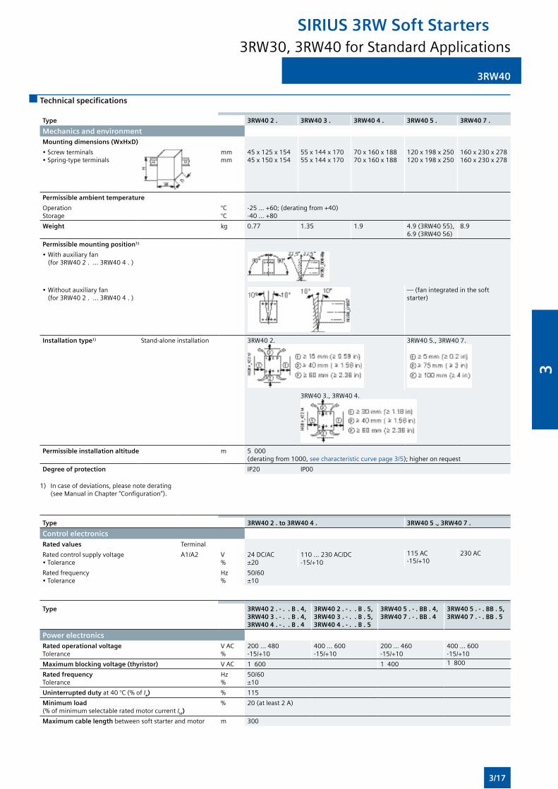
3RW40
Technical specifications
Type 3RW40 2 . 3RW40 3 . 3RW40 4 . 3RW40 5 . 3RW40 7 .
Mechanics and environmentMounting dimensions (WxHxD)
•Screwterminals•Spring-typeterminals
mmmm
45x125x15445x150x154
55x144x17055x144x170
70x160x18870x160x188
120x198x250120x198x250
160x230x278160x230x278
Permissible ambient temperature
OperationStorage
°C°C
-25...+60;(deratingfrom+40)-40...+80
Weight kg 0.77 1.35 1.9 4.9(3RW4055),6.9(3RW4056)
8.9
Permissible mounting position1)
• Withauxiliaryfan (for3RW402....3RW404.)
• Withoutauxiliaryfan (for3RW402....3RW404.)
—(fanintegratedinthesoftstarter)
Installation type1) Stand-alone installation 3RW40 2. 3RW405.,3RW407.
3RW40 3., 3RW40 4.
Permissible installation altitude m 5000(deratingfrom1000,seecharacteristiccurvepage3/5);higheronrequest
Degree of protection IP20 IP00
1) Incaseofdeviations,pleasenotederating (seeManualinChapter“Configuration”).
Type 3RW40 2 . to 3RW40 4 . 3RW40 5 ., 3RW40 7 .
Control electronicsRated values Terminal
Ratedcontrolsupplyvoltage•Tolerance
A1/A2 V%
24DC/AC±20
110...230AC/DC-15/+10
115AC 230 AC-15/+10
Ratedfrequency•Tolerance
Hz%
50/60±10
Type 3RW40 2 . - . . B . 4, 3RW40 3 . - . . B . 4, 3RW40 4 . - . . B . 4
3RW40 2 . - . . B . 5, 3RW40 3 . - . . B . 5, 3RW40 4 . - . . B . 5
3RW40 5 . - . BB . 4, 3RW40 7 . - . BB . 4
3RW40 5 . - . BB . 5, 3RW40 7 . - . BB . 5
Power electronicsRated operational voltageTolerance
VAC%
200 ... 480-15/+10
400 ... 600-15/+10
200 ... 460-15/+10
400 ... 600-15/+10
Maximum blocking voltage (thyristor) VAC 1 600 1 400 1 800
Rated frequencyTolerance
Hz%
50/60±10
Uninterrupted dutyat40°C(%of Ie) % 115
Minimum load (%ofminimumselectableratedmotorcurrent IM)
% 20(atleast2A)
Maximum cable length betweensoftstarterandmotor m 300
3RW30, 3RW40 for Standard Applications
SIRIUS 3RW Soft Starters
3/17
3
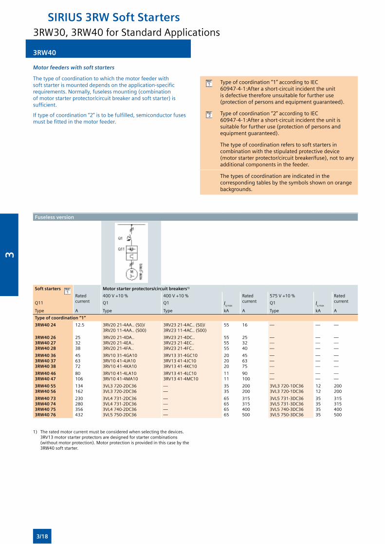
3RW40
Motor feeders with soft starters
Thetypeofcoordinationtowhichthemotorfeederwithsoftstarterismounteddependsontheapplication-specificrequirements.Normally,fuselessmounting(combinationofmotorstarterprotector/circuitbreakerandsoftstarter)issufficient.
Iftypeofcoordination“2”istobefulfilled,semiconductorfusesmustbefittedinthemotorfeeder.
Typeofcoordination“1”accordingtoIEC60947-4-1:Afterashort-circuitincidenttheunitis defective therefore unsuitable for further use (protectionofpersonsandequipmentguaranteed).
Typeofcoordination“2”accordingtoIEC60947-4-1:Afterashort-circuitincidenttheunitissuitableforfurtheruse(protectionofpersonsandequipmentguaranteed).
Thetypeofcoordinationreferstosoftstartersincombinationwiththestipulatedprotectivedevice(motorstarterprotector/circuitbreaker/fuse),nottoanyadditional components in the feeder.
Thetypesofcoordinationareindicatedinthecorrespondingtablesbythesymbolsshownonorangebackgrounds.
Fuseless version
Soft starters Motor starter protectors/circuit breakers1)
Rated current
400V+10% 400V+10% Rated current
575V+10% Rated currentQ11 Q1 Q1 Iqmax
Q1 Iqmax
Type A Type Type kA A Type kA A
Type of coordination “1”
3RW40 24 12.5 3RV2021-4AA..(S0)/3RV2011-4AA..(S00)
3RV2321-4AC..(S0)/3RV2311-4AC..(S00)
55 16 — — —
3RW40 263RW40 273RW40 28
253238
3RV2021-4DA..3RV2021-4EA..3RV2021-4FA..
3RV2321-4DC..3RV2321-4EC..3RV2321-4FC..
555555
253240
———
———
———
3RW40 363RW40 373RW40 38
456372
3RV1031-4GA103RV1041-4JA103RV1041-4KA10
3RV1331-4GC103RV1341-4JC103RV1341-4KC10
202020
456375
———
———
———
3RW40 463RW40 47
80106
3RV1041-4LA103RV1041-4MA10
3RV1341-4LC103RV1341-4MC10
1111
90100
——
——
——
3RW40 553RW40 56
134162
3VL3720-2DC363VL3720-2DC36
——
3535
200200
3VL3720-1DC363VL3720-1DC36
1212
200200
3RW40 733RW40 743RW40 753RW40 76
230280356432
3VL4731-2DC363VL4731-2DC363VL4740-2DC363VL5750-2DC36
————
65656565
315315400500
3VL5731-3DC363VL5731-3DC363VL5740-3DC363VL5750-3DC36
35353535
315315400500
1) Theratedmotorcurrentmustbeconsideredwhenselectingthedevices.3RV13motorstarterprotectorsaredesignedforstartercombinations(withoutmotorprotection).Motorprotectionisprovidedinthiscasebythe3RW40 soft starter.
3RW30, 3RW40 for Standard Applications
SIRIUS 3RW Soft Starters
3/18
3
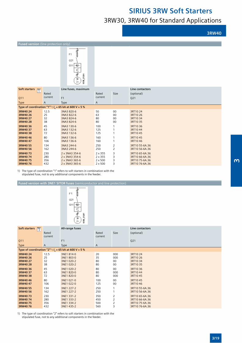
3RW40
Fused version (lineprotectiononly)
Soft starters Line fuses, maximum Line contactors
Rated current
Rated current
Size (optional)
Q11 F1 Q21
Type A Type A
Type of coordination “1”1): Iq = 65 kA at 600 V + 5 %
3RW40 243RW40 263RW40 273RW40 28
12.5253238
3NA3 820-63NA3 822-63NA3 824-63NA3 824-6
50638080
00000000
3RT10243RT10263RT10343RT1035
3RW40 363RW40 373RW40 38
456372
3NA3 130-63NA3 132-63NA3 132-6
100125125
111
3RT10363RT10443RT1045
3RW40 463RW40 47
80106
3NA3 136-63NA3 136-6
160160
11
3RT10453RT1046
3RW40 553RW40 56
134162
3NA3 244-63NA3 244-6
250250
22
3RT1055-6A.363RT1056-6A.36
3RW40 733RW40 743RW40 753RW40 76
230280356432
2x3NA3354-62x3NA3354-62x3NA3365-62x3NA3365-6
2x3552x3552x5002x500
3333
3RT1065-6A.363RT1066-6A.363RT1075-6A.363RT1076-6A.36
1) Thetypeofcoordination“1”referstosoftstartersincombinationwiththe stipulatedfuse,nottoanyadditionalcomponentsinthefeeder.
Fused version with 3NE1 SITOR fuses (semiconductorandlineprotection)
Soft starters All-range fuses Line contactors
Rated current
Rated current
Size (optional)
Q11 F’1 Q21
Type A Type A
Type of coordination “2”1): Iq = 65 kA at 600 V + 5 %
3RW40 243RW40 263RW40 273RW40 28
12.5253238
3NE1814-03NE1803-03NE1020-23NE1020-2
20358080
0000000000
3RT10243RT10263RT10343RT1035
3RW40 363RW40 373RW40 38
456372
3NE1020-23NE1820-03NE1820-0
808080
00000000
3RT10363RT10443RT1045
3RW40 463RW40 47
80106
3NE1021-03NE1022-0
100125
0000
3RT10453RT1046
3RW40 553RW40 56
134162
3NE1227-23NE1227-2
250250
11
3RT1055-6A.363RT1056-6A.36
3RW40 733RW40 743RW40 753RW40 76
230280356432
3NE1331-23NE1333-23NE1334-23NE1435-2
350450500560
2223
3RT1065-6A.363RT1066-6A.363RT1075-6A.363RT1076-6A.36
1) Thetypeofcoordination“2”referstosoftstartersincombinationwiththe stipulatedfuse,nottoanyadditionalcomponentsinthefeeder.
3RW30, 3RW40 for Standard Applications
SIRIUS 3RW Soft Starters
3/19
3
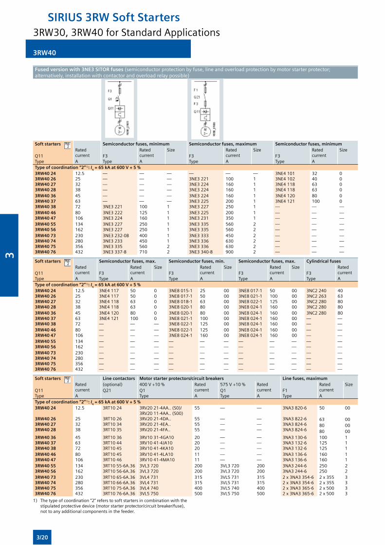
3RW40
Fused version with 3NE3 SITOR fuses (semiconductorprotectionbyfuse,lineandoverloadprotectionbymotorstarterprotector;alternatively,installationwithcontactorandoverloadrelaypossible)
Soft starters Semiconductor fuses, minimum Semiconductor fuses, maximum Semiconductor fuses, minimumRated current
Rated current
Size Rated current
Size Rated current
SizeQ11Type
F3Type
F3Type
F3TypeA A A A
Type of coordination “2”1): Iq = 65 kA at 600 V + 5 %3RW40 243RW40 263RW40 273RW40 28
12.5253238
————
————
————
—3NE32213NE32243NE3224
—100160160
—111
3NE41013NE41023NE41183NE4118
32406363
0000
3RW40 363RW40 373RW40 38
456372
——3NE3221
——100
——1
3NE32243NE32253NE3227
160200250
111
3NE41203NE4121—
80100—
00—
3RW40 463RW40 47
80106
3NE32223NE3224
125160
11
3NE32253NE3231
200350
11
——
——
——
3RW40 553RW40 56
134162
3NE32273NE3227
250250
11
3NE33353NE3335
560560
22
——
——
——
3RW40 733RW40 743RW40 753RW40 76
230280356432
3NE3232-0B3NE32333NE33353NE3337-8
400450560710
1122
3NE33333NE33363NE33363NE3340-8
450630630900
2222
————
————
————
Soft starters Semiconductor fuses, max. Semiconductor fuses, min. Semiconductor fuses, max. Cylindrical fusesRated current
Rated current
Size Rated current
Size Rated current
Size Rated currentQ11
TypeF3Type
F3Type
F3Type
F3TypeA A A A A
Type of coordination “2”1): Iq = 65 kA at 600 V + 5 %3RW40 243RW40 263RW40 273RW40 28
12.5253238
3NE41173NE41173NE41183NE4118
50506363
0000
3NE8015-13NE8017-13NE8018-13NE8020-1
25506380
00000000
3NE8017-13NE8021-13NE8022-13NE8024-1
50100125160
00000000
3NC2 2403NC2 2633NC2 2803NC2 280
40638080
3RW40 363RW40 373RW40 38
456372
3NE41203NE4121—
80100—
00—
3NE8020-13NE8021-13NE8022-1
80100125
000000
3NE8024-13NE8024-13NE8024-1
160160160
000000
3NC2 280——
80——
3RW40 463RW40 47
80106
——
——
——
3NE8022-13NE8024-1
125160
0000
3NE8024-13NE8024-1
160160
0000
——
——
3RW40 553RW40 56
134162
——
——
——
——
——
——
——
——
——
——
——
3RW40 733RW40 743RW40 753RW40 76
230280356432
————
————
————
————
————
————
————
————
————
————
————
Soft starters Line contactors Motor starter protectors/circuit breakers Line fuses, maximumRated current
(optional) 400V+10% Rated current
575V+10% Rated current
Rated current
SizeQ11Type
Q21 Q1Type
Q1Type
F1TypeA A A A
Type of coordination “2”1): Iq = 65 kA at 600 V + 5 %3RW40 24
3RW40 263RW40 273RW40 28
12.5
253238
3RT1024
3RT10263RT10343RT1035
3RV2021-4AA..(S0)/3RV2011-4AA..(S00)3RV2021-4DA..3RV2021-4EA..3RV2021-4FA..
55
555555
—
———
—
———
3NA3 820-6
3NA3 822-63NA3 824-63NA3 824-6
50 00
63 0080 0080 00
3RW40 363RW40 373RW40 38
456372
3RT10363RT10443RT1045
3RV1031-4GA103RV1041-4JA103RV1041-4KA10
202020
———
———
3NA3 130-63NA3 132-63NA3 132-6
100125125
111
3RW40 463RW40 47
80106
3RT10453RT1046
3RV1041-4LA103RV1041-4MA10
1111
——
——
3NA3 136-63NA3 136-6
160160
11
3RW40 553RW40 56
134162
3RT1055-6A.363RT1056-6A.36
3VL37203VL3720
200200
3VL37203VL3720
200200
3NA3 244-63NA3 244-6
250250
22
3RW40 733RW40 743RW40 753RW40 76
230280356432
3RT1065-6A.363RT1066-6A.363RT1075-6A.363RT1076-6A.36
3VL47313VL47313VL47403VL5750
315315400500
3VL57313VL57313VL57403VL5750
315315400500
2x3NA3354-62x3NA3354-62x3NA3365-62x3NA3365-6
2x3552x3552x5002x500
3333
1) Thetypeofcoordination“2”referstosoftstartersincombinationwiththestipulatedprotectivedevice(motorstarterprotector/circuitbreaker/fuse),nottoanyadditionalcomponentsinthefeeder.
3RW30, 3RW40 for Standard Applications
SIRIUS 3RW Soft Starters
3/20
3
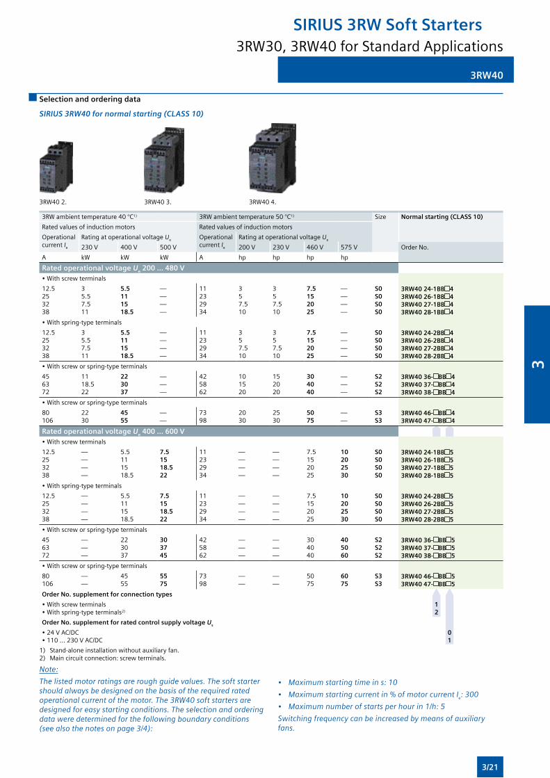
3RW40
1) Stand-aloneinstallationwithoutauxiliaryfan.2) Maincircuitconnection:screwterminals.
Selection and ordering data
SIRIUS 3RW40 for normal starting (CLASS 10)
3RW40 2. 3RW40 3. 3RW40 4.
3RW ambient temperature 40 °C1) 3RWambienttemperature50°C1) Size Normal starting (CLASS 10)
Rated values of induction motors Rated values of induction motors
Operational current Ie
Rating at operational voltage Ue Operational current Ie
Rating at operational voltage Ue
230V 400V 500V 200V 230V 460V 575V Order No.
A kW kW kW A hp hp hp hp
Rated operational voltage Ue 200 ... 480 V•Withscrewterminals
12.5253238
35.57.511
5.5111518.5
————
11232934
357.510
357.510
7.5152025
————
S0S0S0S0
3RW40 24-1BB 43RW40 26-1BB 43RW40 27-1BB 43RW40 28-1BB 4
•Withspring-typeterminals
12.5253238
35.57.511
5.5111518.5
————
11232934
357.510
357.510
7.5152025
————
S0S0S0S0
3RW40 24-2BB 43RW40 26-2BB 43RW40 27-2BB 43RW40 28-2BB 4
•Withscreworspring-typeterminals
456372
1118.522
223037
———
425862
101520
152020
304040
———
S2S2S2
3RW40 36- BB 43RW40 37- BB 43RW40 38- BB 4
•Withscreworspring-typeterminals
80106
2230
4555
——
7398
2030
2530
5075
——
S3S3
3RW40 46- BB 43RW40 47- BB 4
Rated operational voltage Ue 400 ... 600 V•Withscrewterminals
12.5253238
————
5.5111518.5
7.51518.522
11232934
————
————
7.5152025
10202530
S0S0S0S0
3RW40 24-1BB 53RW40 26-1BB 53RW40 27-1BB 53RW40 28-1BB 5
•Withspring-typeterminals
12.5253238
————
5.5111518.5
7.51518.522
11232934
————
————
7.5152025
10202530
S0S0S0S0
3RW40 24-2BB 53RW40 26-2BB 53RW40 27-2BB 53RW40 28-2BB 5
•Withscreworspring-typeterminals
456372
———
223037
303745
425862
———
———
304040
405060
S2S2S2
3RW40 36- BB 53RW40 37- BB 53RW40 38- BB 5
•Withscreworspring-typeterminals
80106
——
4555
5575
7398
——
——
5075
6075
S3S3
3RW40 46- BB 53RW40 47- BB 5
Order No. supplement for connection types
•Withscrewterminals•Withspring-typeterminals2)
1 2
Order No. supplement for rated control supply voltage Us
•24VAC/DC•110...230VAC/DC
0 1
Note:
The listed motor ratings are rough guide values. The soft starter should always be designed on the basis of the required rated operational current of the motor. The 3RW40 soft starters are designed for easy starting conditions. The selection and ordering data were determined for the following boundary conditions (see also the notes on page 3/4):
• Maximum starting time in s: 10
• Maximum starting current in % of motor current Ie: 300
• Maximum number of starts per hour in 1/h: 5
Switching frequency can be increased by means of auxiliary fans.
3RW30, 3RW40 for Standard Applications
SIRIUS 3RW Soft Starters
3/21
3
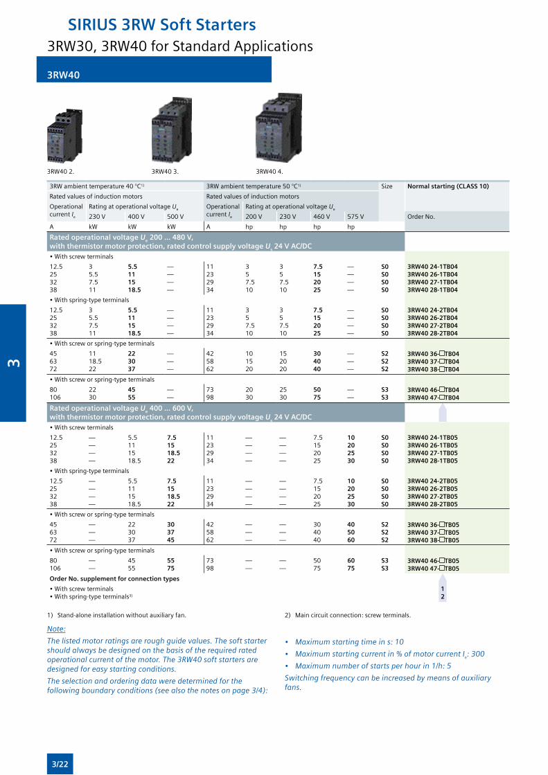
3RW40
1) Stand-aloneinstallationwithoutauxiliaryfan. 2) Maincircuitconnection:screwterminals.
Note:
The listed motor ratings are rough guide values. The soft starter should always be designed on the basis of the required rated operational current of the motor. The 3RW40 soft starters are designed for easy starting conditions.
The selection and ordering data were determined for the following boundary conditions (see also the notes on page 3/4):
• Maximum starting time in s: 10
• Maximum starting current in % of motor current Ie: 300
• Maximum number of starts per hour in 1/h: 5
Switching frequency can be increased by means of auxiliary fans.
3RW40 2. 3RW40 3. 3RW40 4.
3RW ambient temperature 40 °C1) 3RWambienttemperature50°C1) Size Normal starting (CLASS 10)
Rated values of induction motors Rated values of induction motors
Operational current Ie
Rating at operational voltage Ue Operational current Ie
Rating at operational voltage Ue
230V 400V 500V 200V 230V 460V 575V Order No.
A kW kW kW A hp hp hp hp
Rated operational voltage Ue 200 ... 480 V, with thermistor motor protection, rated control supply voltage Us 24 V AC/DC•Withscrewterminals
12.5253238
35.57.511
5.5111518.5
————
11232934
357.510
357.510
7.5152025
————
S0S0S0S0
3RW40 24-1TB043RW40 26-1TB043RW40 27-1TB043RW40 28-1TB04
•Withspring-typeterminals
12.5253238
35.57.511
5.5111518.5
————
11232934
357.510
357.510
7.5152025
————
S0S0S0S0
3RW40 24-2TB043RW40 26-2TB043RW40 27-2TB043RW40 28-2TB04
•Withscreworspring-typeterminals
456372
1118.522
223037
———
425862
101520
152020
304040
———
S2S2S2
3RW40 36- TB043RW40 37- TB043RW40 38- TB04
•Withscreworspring-typeterminals
80106
2230
4555
——
7398
2030
2530
5075
——
S3S3
3RW40 46- TB043RW40 47- TB04
Rated operational voltage Ue 400 ... 600 V, with thermistor motor protection, rated control supply voltage Us 24 V AC/DC•Withscrewterminals
12.5253238
————
5.5111518.5
7.51518.522
11232934
————
————
7.5152025
10202530
S0S0S0S0
3RW40 24-1TB053RW40 26-1TB053RW40 27-1TB053RW40 28-1TB05
•Withspring-typeterminals
12.5253238
————
5.5111518.5
7.51518.522
11232934
————
————
7.5152025
10202530
S0S0S0S0
3RW40 24-2TB053RW40 26-2TB053RW40 27-2TB053RW40 28-2TB05
•Withscreworspring-typeterminals
456372
———
223037
303745
425862
———
———
304040
405060
S2S2S2
3RW40 36- TB053RW40 37- TB053RW40 38- TB05
•Withscreworspring-typeterminals
80106
——
4555
5575
7398
——
——
5075
6075
S3S3
3RW40 46- TB053RW40 47- TB05
Order No. supplement for connection types
•Withscrewterminals•Withspring-typeterminals3)
1 2
3RW30, 3RW40 for Standard Applications
SIRIUS 3RW Soft Starters
3/22
3
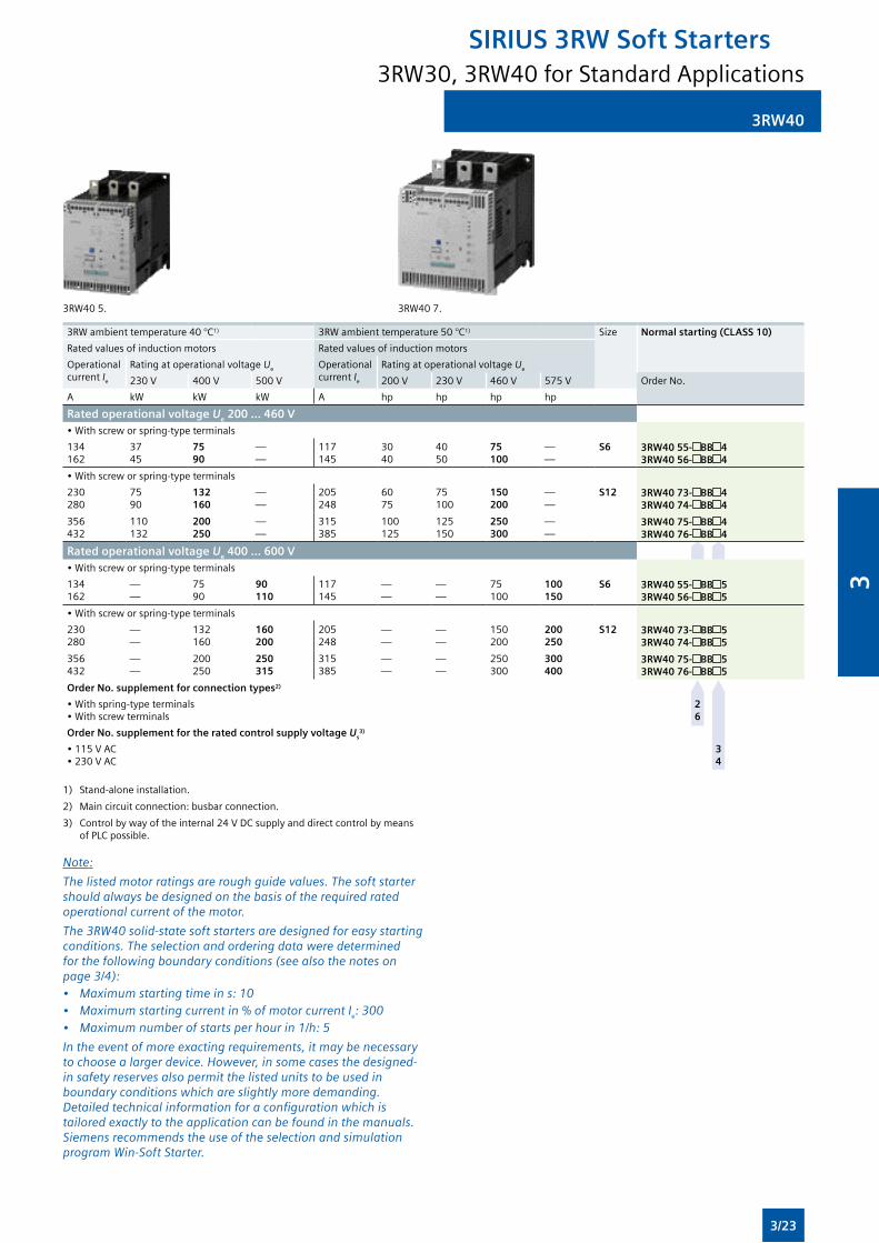
3RW40
3RW405. 3RW407.
3RW ambient temperature 40 °C1) 3RWambienttemperature50°C1) Size Normal starting (CLASS 10)
Rated values of induction motors Rated values of induction motors
Operational current Ie
Rating at operational voltage Ue Operational current Ie
Rating at operational voltage Ue
230V 400V 500V 200V 230V 460V 575V Order No.
A kW kW kW A hp hp hp hp
Rated operational voltage Ue 200 ... 460 V•Withscreworspring-typeterminals
134162
3745
7590
——
117145
3040
4050
75100
——
S6 3RW40 55- BB 43RW40 56- BB 4
•Withscreworspring-typeterminals
230280
7590
132160
——
205248
6075
75100
150200
——
S12 3RW40 73- BB 43RW40 74- BB 4
356432
110132
200250
——
315385
100125
125150
250300
——
3RW40 75- BB 43RW40 76- BB 4
Rated operational voltage Ue 400 ... 600 V•Withscreworspring-typeterminals
134162
——
7590
90110
117145
——
——
75100
100150
S6 3RW40 55- BB 53RW40 56- BB 5
•Withscreworspring-typeterminals
230280
——
132160
160200
205248
——
——
150200
200250
S12 3RW40 73- BB 53RW40 74- BB 5
356432
——
200250
250315
315385
——
——
250300
300400
3RW40 75- BB 53RW40 76- BB 5
Order No. supplement for connection types2)
•Withspring-typeterminals•Withscrewterminals
2 6
Order No. supplement for the rated control supply voltage Us3)
•115VAC•230VAC
3 4
1) Stand-aloneinstallation.
2) Maincircuitconnection:busbarconnection.
3) Controlbywayoftheinternal24VDCsupplyanddirectcontrolbymeansofPLCpossible.
Note:
The listed motor ratings are rough guide values. The soft starter should always be designed on the basis of the required rated operational current of the motor.
The 3RW40 solid-state soft starters are designed for easy starting conditions. The selection and ordering data were determined for the following boundary conditions (see also the notes on page 3/4):• Maximum starting time in s: 10• Maximum starting current in % of motor current Ie: 300• Maximum number of starts per hour in 1/h: 5
In the event of more exacting requirements, it may be necessary to choose a larger device. However, in some cases the designed-in safety reserves also permit the listed units to be used in boundary conditions which are slightly more demanding. Detailed technical information for a configuration which is tailored exactly to the application can be found in the manuals. Siemens recommends the use of the selection and simulation program Win-Soft Starter.
3RW30, 3RW40 for Standard Applications
SIRIUS 3RW Soft Starters
3/23
3
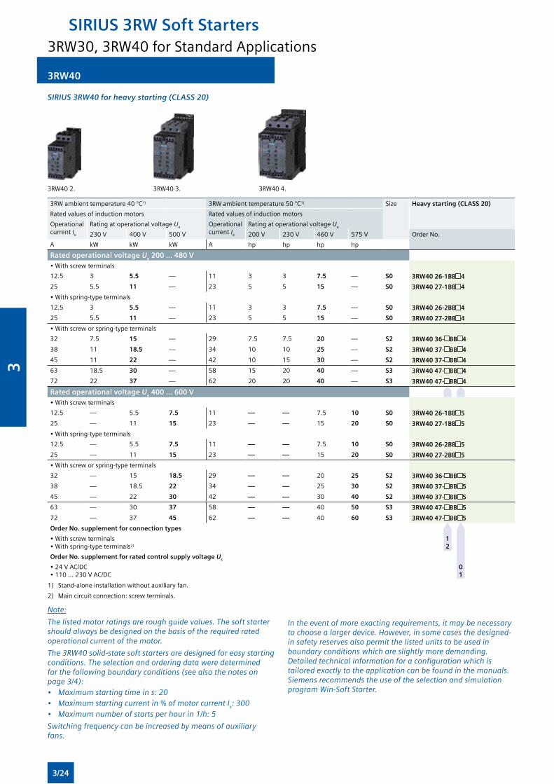
3RW40
SIRIUS 3RW40 for heavy starting (CLASS 20)
3RW40 2. 3RW40 3. 3RW40 4.
3RW ambient temperature 40 °C1) 3RWambienttemperature50°C1) Size Heavy starting (CLASS 20)
Rated values of induction motors Rated values of induction motors
Operational current Ie
Rating at operational voltage Ue Operational current Ie
Rating at operational voltage Ue
230V 400V 500V 200V 230V 460V 575V Order No.
A kW kW kW A hp hp hp hp
Rated operational voltage Ue 200 ... 480 V•Withscrewterminals
12.5 3 5.5 — 11 3 3 7.5 — S0 3RW40 26-1BB 4
25 5.5 11 — 23 5 5 15 — S0 3RW40 27-1BB 4
•Withspring-typeterminals
12.5 3 5.5 — 11 3 3 7.5 — S0 3RW40 26-2BB 4
25 5.5 11 — 23 5 5 15 — S0 3RW40 27-2BB 4
•Withscreworspring-typeterminals
32 7.5 15 — 29 7.5 7.5 20 — S2 3RW40 36- BB 4
38 11 18.5 — 34 10 10 25 — S2 3RW40 37- BB 4
45 11 22 — 42 10 15 30 — S2 3RW40 37- BB 4
63 18.5 30 — 58 15 20 40 — S3 3RW40 47- BB 4
72 22 37 — 62 20 20 40 — S3 3RW40 47- BB 4
Rated operational voltage Ue 400 ... 600 V•Withscrewterminals
12.5 — 5.5 7.5 11 — — 7.5 10 S0 3RW40 26-1BB 5
25 — 11 15 23 — — 15 20 S0 3RW40 27-1BB 5
•Withspring-typeterminals
12.5 — 5.5 7.5 11 — — 7.5 10 S0 3RW40 26-2BB 5
25 — 11 15 23 — — 15 20 S0 3RW40 27-2BB 5
•Withscreworspring-typeterminals
32 — 15 18.5 29 — — 20 25 S2 3RW40 36- BB 5
38 — 18.5 22 34 — — 25 30 S2 3RW40 37- BB 5
45 — 22 30 42 — — 30 40 S2 3RW40 37- BB 5
63 — 30 37 58 — — 40 50 S3 3RW40 47- BB 5
72 — 37 45 62 — — 40 60 S3 3RW40 47- BB 5
Order No. supplement for connection types
•Withscrewterminals•Withspring-typeterminals2)
1 2
Order No. supplement for rated control supply voltage Us
•24VAC/DC•110...230VAC/DC
0 1
1) Stand-aloneinstallationwithoutauxiliaryfan.
2) Maincircuitconnection:screwterminals.
Note:
The listed motor ratings are rough guide values. The soft starter should always be designed on the basis of the required rated operational current of the motor.
The 3RW40 solid-state soft starters are designed for easy starting conditions. The selection and ordering data were determined for the following boundary conditions (see also the notes on page 3/4):• Maximum starting time in s: 20• Maximum starting current in % of motor current Ie: 300• Maximum number of starts per hour in 1/h: 5
Switching frequency can be increased by means of auxiliary fans.
In the event of more exacting requirements, it may be necessary to choose a larger device. However, in some cases the designed-in safety reserves also permit the listed units to be used in boundary conditions which are slightly more demanding. Detailed technical information for a configuration which is tailored exactly to the application can be found in the manuals. Siemens recommends the use of the selection and simulation program Win-Soft Starter.
3RW30, 3RW40 for Standard Applications
SIRIUS 3RW Soft Starters
3/24
3
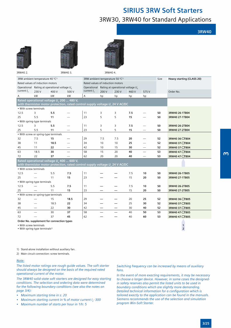
3RW40
3RW40 2. 3RW40 3. 3RW40 4.
3RW ambient temperature 40 °C1) 3RWambienttemperature50°C1) Size Heavy starting (CLASS 20)
Rated values of induction motors Rated values of induction motors
Operational current Ie
Rating at operational voltage Ue Operational current Ie
Rating at operational voltage Ue
230V 400V 500V 200V 230V 460V 575V Order No.
A kW kW kW A hp hp hp hp
Rated operational voltage Ue 200 ... 480 V, with thermistor motor protection, rated control supply voltage Us 24 V AC/DC•Withscrewterminals
12.5 3 5.5 — 11 3 3 7.5 — S0 3RW40 26-1TB04
25 5.5 11 — 23 5 5 15 — S0 3RW40 27-1TB04
•Withspring-typeterminals
12.5 3 5.5 — 11 3 3 7.5 — S0 3RW40 26-2TB04
25 5.5 11 — 23 5 5 15 — S0 3RW40 27-2TB04
•Withscreworspring-typeterminals
32 7.5 15 — 29 7.5 7.5 20 — S2 3RW40 36- TB04
38 11 18.5 — 34 10 10 25 — S2 3RW40 37- TB04
45 11 22 — 42 10 15 30 — S2 3RW40 37- TB04
63 18.5 30 — 58 15 20 40 — S3 3RW40 47- TB04
72 22 37 — 62 20 20 40 — S3 3RW40 47- TB04
Rated operational voltage Ue 400 ... 600 V, with thermistor motor protection, rated control supply voltage Us 24 V AC/DC•Withscrewterminals
12.5 — 5.5 7.5 11 — — 7.5 10 S0 3RW40 26-1TB05
25 — 11 15 23 — — 15 20 S0 3RW40 27-1TB05
•Withspring-typeterminals
12.5 — 5.5 7.5 11 — — 7.5 10 S0 3RW40 26-2TB05
25 — 11 15 23 — — 15 20 S0 3RW40 27-2TB05
•Withscreworspring-typeterminals
32 — 15 18.5 29 — — 20 25 S2 3RW40 36- TB05
38 — 18.5 22 34 — — 25 30 S2 3RW40 37- TB05
45 — 22 30 42 — — 30 40 S2 3RW40 37- TB05
63 — 30 37 58 — — 40 50 S3 3RW40 47- TB05
72 — 37 45 62 — — 40 60 S3 3RW40 47- TB05
Order No. supplement for connection types
•Withscrewterminals•Withspring-typeterminals2)
1 2
1) Stand-aloneinstallationwithoutauxiliaryfan.
2) Maincircuitconnection:screwterminals.
Note:
The listed motor ratings are rough guide values. The soft starter should always be designed on the basis of the required rated operational current of the motor.
The 3RW40 solid-state soft starters are designed for easy starting conditions. The selection and ordering data were determined for the following boundary conditions (see also the notes on page 3/4):• Maximum starting time in s: 20• Maximum starting current in % of motor current Ie: 300• Maximum number of starts per hour in 1/h: 5
Switching frequency can be increased by means of auxiliary fans.
In the event of more exacting requirements, it may be necessary to choose a larger device. However, in some cases the designed-in safety reserves also permit the listed units to be used in boundary conditions which are slightly more demanding. Detailed technical information for a configuration which is tailored exactly to the application can be found in the manuals. Siemens recommends the use of the selection and simulation program Win-Soft Starter.
3RW30, 3RW40 for Standard Applications
SIRIUS 3RW Soft Starters
3/25
3
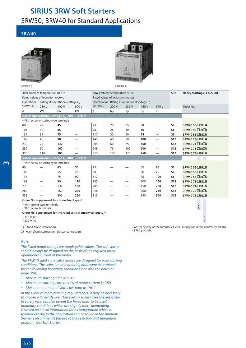
3RW40
3RW405. 3RW407.
3RW ambient temperature 40 °C1) 3RWambienttemperature50°C1) Size Heavy starting (CLASS 20)
Rated values of induction motors Rated values of induction motors
Operational current Ie
Rating at operational voltage Ue Operational current Ie
Rating at operational voltage Ue
230V 400V 500V 200V 230V 460V 575V Order No.
A kW kW kW A hp hp hp hp
Rated operational voltage Ue 200 ... 460 V•Withscreworspring-typeterminals
80 22 45 — 73 20 25 50 — S6 3RW40 55- BB 4
106 30 55 — 98 25 30 60 — S6 3RW40 55- BB 4
134 37 75 — 117 30 40 75 — S6 3RW40 56- BB 4
162 45 90 — 145 40 50 100 — S12 3RW40 73- BB 4
230 75 132 — 205 60 75 150 — S12 3RW40 74- BB 4
280 90 160 — 248 75 100 200 — S12 3RW40 75- BB 4
356 110 200 — 315 100 125 250 — S12 3RW40 76- BB 4
Rated operational voltage Ue 400 ... 600 V•Withscreworspring-typeterminals
80 — 45 55 73 — — 50 60 S6 3RW40 55- BB 5
106 — 55 75 98 — — 60 75 S6 3RW40 55- BB 5
134 — 75 90 117 — — 75 100 S6 3RW40 56- BB 5
162 — 90 110 145 — — 100 150 S12 3RW40 73- BB 5
230 — 132 160 205 — — 150 200 S12 3RW40 74- BB 5
280 — 160 200 248 — — 200 250 S12 3RW40 75- BB 5
356 — 200 250 315 — — 250 300 S12 3RW40 76- BB 5
Order No. supplement for connection types2)
•Withspring-typeterminals•Withscrewterminals
2 6
Order No. supplement for the rated control supply voltage Us3)
•115VAC•230VAC
3 4
1) Stand-aloneinstallation.
2) Maincircuitconnection:busbarconnection.
3) Controlbywayoftheinternal24VDCsupplyanddirectcontrolbymeansofPLCpossible.
Note:
The listed motor ratings are rough guide values. The soft starter should always be designed on the basis of the required rated operational current of the motor.
The 3RW40 solid-state soft starters are designed for easy starting conditions. The selection and ordering data were determined for the following boundary conditions (see also the notes on page 3/4):• Maximum starting time in s: 40• Maximum starting current in % of motor current Ie: 350• Maximum number of starts per hour in 1/h: 1
In the event of more exacting requirements, it may be necessary to choose a larger device. However, in some cases the designed-in safety reserves also permit the listed units to be used in boundary conditions which are slightly more demanding. Detailed technical information for a configuration which is tailored exactly to the application can be found in the manuals. Siemens recommends the use of the selection and simulation program Win-Soft Starter.
3RW30, 3RW40 for Standard Applications
SIRIUS 3RW Soft Starters
3/26
3
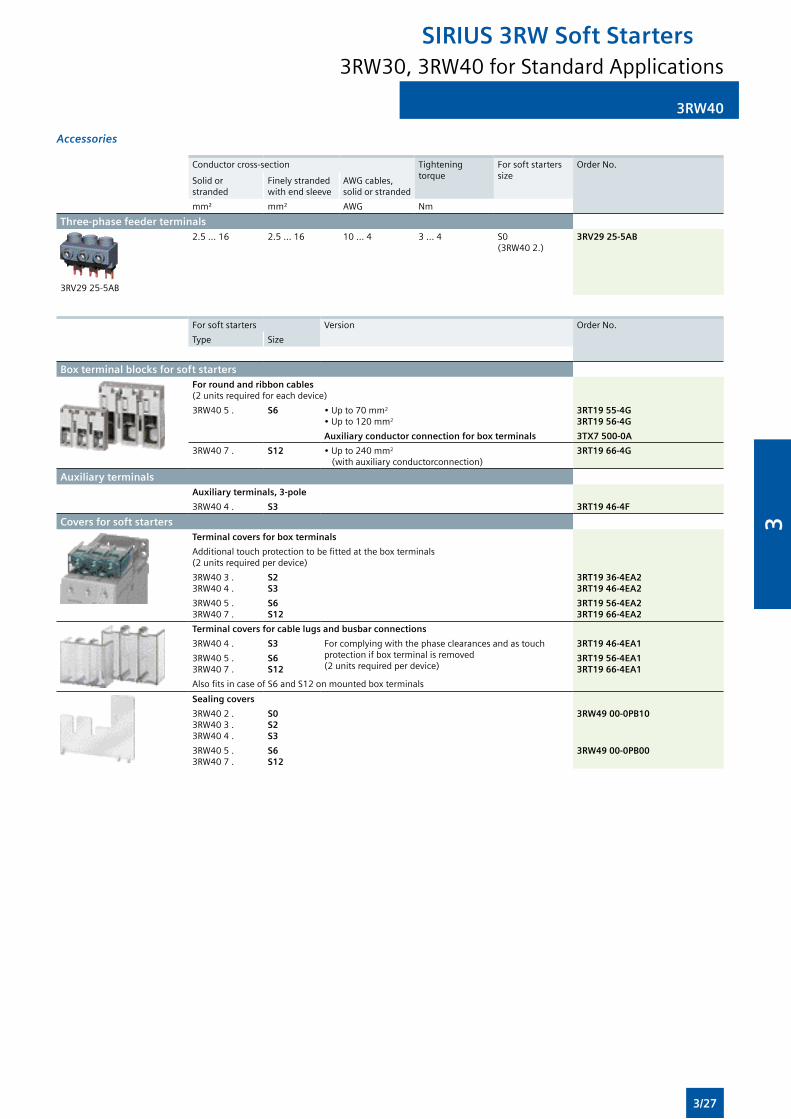
3RW40
Accessories
Conductor cross-section Tighteningtorque
For soft starters size
Order No.
Solid or stranded
Finelystrandedwithendsleeve
AWG cables, solid or stranded
mm² mm² AWG Nm
Three-phase feeder terminals
3RV2925-5AB
2.5...16 2.5...16 10 ... 4 3 ... 4 S0 (3RW402.)
3RV29 25-5AB
For soft starters Version Order No.
Type Size
Box terminal blocks for soft startersFor round and ribbon cables(2unitsrequiredforeachdevice)
3RW405. S6 •Upto70mm2
•Upto120mm2
3RT19 55-4G3RT19 56-4G
Auxiliary conductor connection for box terminals 3TX7 500-0A
3RW407. S12 •Upto240mm2
(withauxiliaryconductorconnection)3RT19 66-4G
Auxiliary terminalsAuxiliary terminals, 3-pole
3RW40 4 . S3 3RT19 46-4F
Covers for soft startersTerminal covers for box terminals
Additionaltouchprotectiontobefittedattheboxterminals(2unitsrequiredperdevice)
3RW40 3 . 3RW40 4 .
S2S3
3RT19 36-4EA23RT19 46-4EA2
3RW405.3RW407.
S6S12
3RT19 56-4EA23RT19 66-4EA2
Terminal covers for cable lugs and busbar connections
3RW40 4 . S3 Forcomplyingwiththephaseclearancesandastouchprotectionifboxterminalisremoved(2unitsrequiredperdevice)
3RT19 46-4EA1
3RW405.3RW407.
S6S12
3RT19 56-4EA13RT19 66-4EA1
AlsofitsincaseofS6andS12onmountedboxterminals
Sealing covers
3RW40 2 . 3RW40 3 . 3RW40 4 .
S0S2S3
3RW49 00-0PB10
3RW405.3RW407.
S6S12
3RW49 00-0PB00
3RW30, 3RW40 for Standard Applications
SIRIUS 3RW Soft Starters
3/27
3
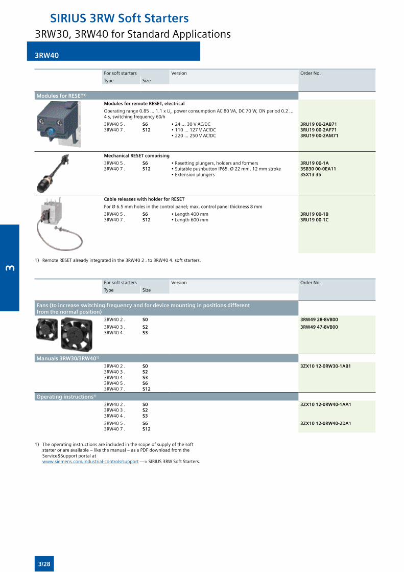
For soft starters Version Order No.
Type Size
Modules for RESET1)
Modules for remote RESET, electrical
Operatingrange0.85...1.1x Us,powerconsumptionAC80VA,DC70W,ONperiod0.2...4s,switchingfrequency60/h
3RW405.3RW407.
S6S12
•24...30VAC/DC•110...127VAC/DC•220...250VAC/DC
3RU19 00-2AB713RU19 00-2AF713RU19 00-2AM71
Mechanical RESET comprising
3RW405.3RW407.
S6 S12
•Resettingplungers,holdersandformers•SuitablepushbuttonIP65,Ø22mm,12mmstroke•Extensionplungers
3RU19 00-1A3SB30 00-0EA113SX13 35
Cable releases with holder for RESET
ForØ6.5mmholesinthecontrolpanel;max.controlpanelthickness8mm
3RW405.3RW407.
S6S12
•Length400mm•Length600mm
3RU19 00-1B3RU19 00-1C
1) RemoteRESETalreadyintegratedinthe3RW402.to3RW404.softstarters.
For soft starters Version Order No.
Type Size
Fans (to increase switching frequency and for device mounting in positions different from the normal position)
3RW40 2 . S0 3RW49 28-8VB00
3RW40 3 . 3RW40 4 .
S2S3
3RW49 47-8VB00
Manuals 3RW30/3RW401) 3RW40 2 . 3RW40 3 . 3RW40 4 . 3RW405.3RW407.
S0S2S3S6S12
3ZX10 12-0RW30-1AB1
Operating instructions1) 3RW40 2 . 3RW40 3 . 3RW40 4 .
S0S2S3
3ZX10 12-0RW40-1AA1
3RW405.3RW407.
S6S12
3ZX10 12-0RW40-2DA1
3RW40
1) Theoperatinginstructionsareincludedinthescopeofsupplyofthesoftstarterorareavailable–likethemanual–asaPDFdownloadfromtheService&Support portal at www.siemens.com/industrial-controls/support —>SIRIUS3RWSoftStarters.
3RW30, 3RW40 for Standard Applications
SIRIUS 3RW Soft Starters
3/28
3
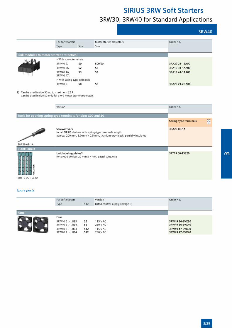
3RW40
For soft starters Motorstarterprotectors Order No.
Type Size Size
Link modules to motor starter protectors1)
•Withscrewterminals
3RW40 2. S0 S00/S0 3RA29 21-1BA00
3RW40 36. S2 S2 3RA19 31-1AA00
3RW40 46., 3RW4047.
S3 S3 3RA19 41-1AA00
•Withspring-typeterminals
3RW40 2. S0 S0 3RA29 21-2GA00
1) CanbeusedinsizeS0uptomaximum32A. CanbeusedinsizeS0onlyfor3RV2motorstarterprotectors.
Version Order No.
Tools for opening spring-type terminals for sizes S00 and S0
Spring-type terminals
3RA29 08-1A
ScrewdriversforallSIRIUSdeviceswithspring-typeterminalslengthapprox.200mm,3.0mmx0.5mm,titaniumgray/black,partiallyinsulated
3RA29 08-1A
Blank labels
3RT1900-1SB20
Unit labeling plates1)
forSIRIUSdevices20mmx7mm,pastelturquoise3RT19 00-1SB20
Spare parts
For soft starters Version Order No.
Type Size RatedcontrolsupplyvoltageUs
FansFans
3RW405.-.BB3.3RW405.-.BB4.
S6S6
115VAC230VAC
3RW49 36-8VX303RW49 36-8VX40
3RW407.-.BB3.3RW407.-.BB4.
S12S12
115VAC230VAC
3RW49 47-8VX303RW49 47-8VX40
3RW30, 3RW40 for Standard Applications
SIRIUS 3RW Soft Starters
3/29
3
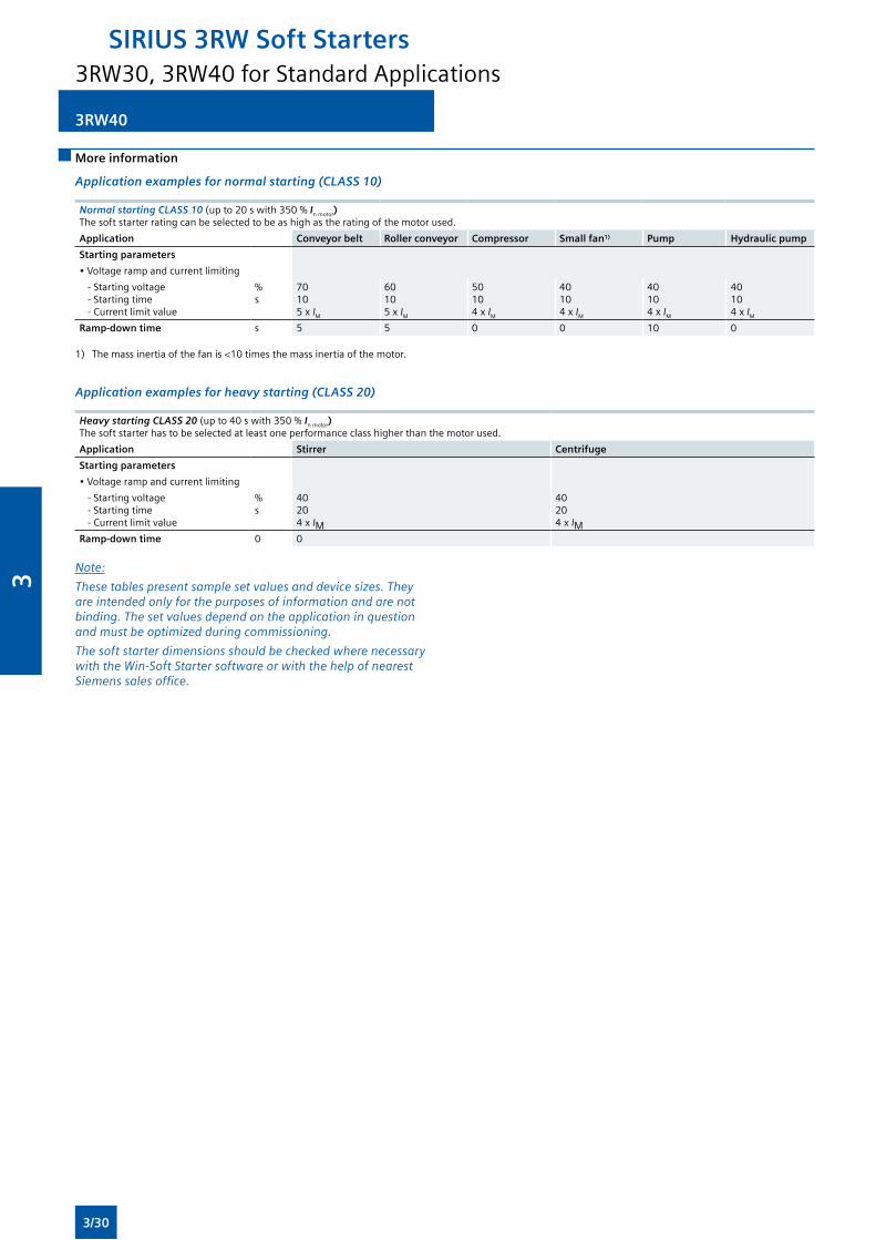
3RW40
More information
Application examples for normal starting (CLASS 10)
Normal starting CLASS 10 (upto20swith350% In motor) Thesoftstarterratingcanbeselectedtobeashighastheratingofthemotorused.
Application Conveyor belt Roller conveyor Compressor Small fan1) Pump Hydraulic pump
Starting parameters
•Voltagerampandcurrentlimiting
- Starting voltage - Starting time - Current limit value
%s
70105x IM
60105x IM
50104x IM
40104x IM
40104x IM
40104x IM
Ramp-down time s 5 5 0 0 10 0
1) Themassinertiaofthefanis<10timesthemassinertiaofthemotor.
Application examples for heavy starting (CLASS 20)
Heavy starting CLASS 20 (upto40swith350% In motor) Thesoftstarterhastobeselectedatleastoneperformanceclasshigherthanthemotorused.
Application Stirrer Centrifuge
Starting parameters
•Voltagerampandcurrentlimiting
- Starting voltage - Starting time - Current limit value
%s
40204x IM
40204x IM
Ramp-down time 0 0
Note:
These tables present sample set values and device sizes. They are intended only for the purposes of information and are not binding. The set values depend on the application in question and must be optimized during commissioning.
The soft starter dimensions should be checked where necessary with the Win-Soft Starter software or with the help of nearest Siemens sales office.
3RW30, 3RW40 for Standard Applications
SIRIUS 3RW Soft Starters
3/30
3
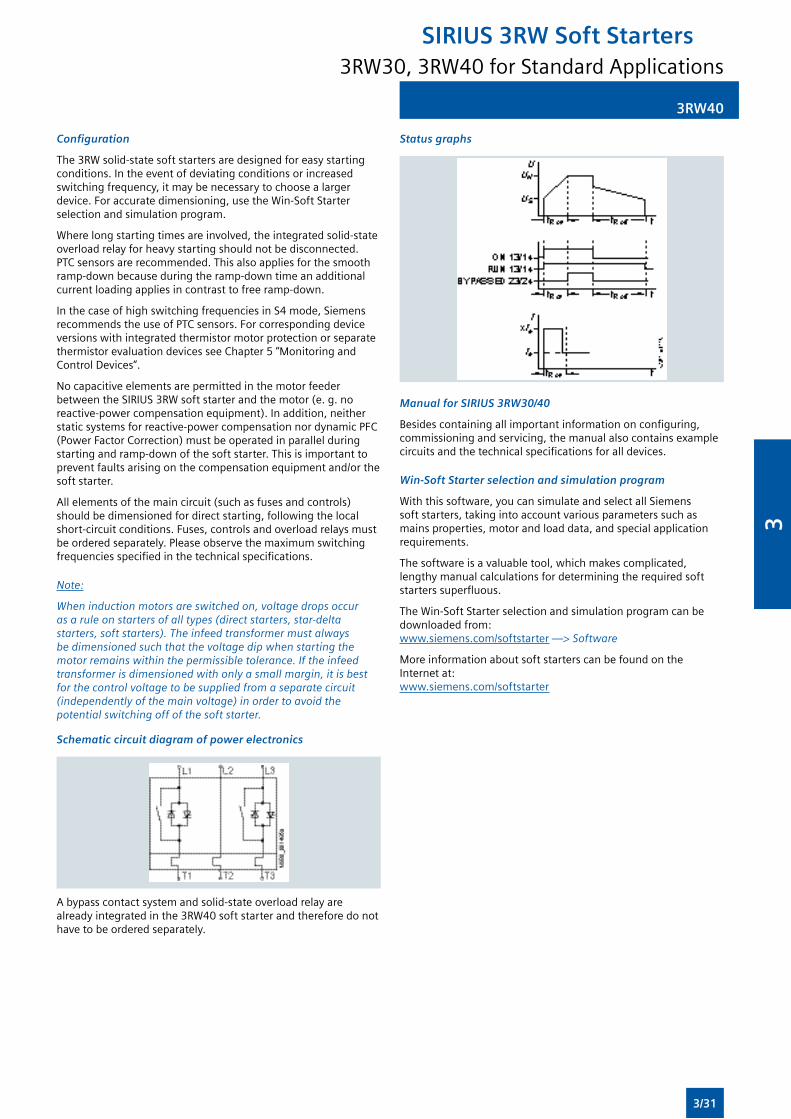
3RW40
Configuration
The3RWsolid-statesoftstartersaredesignedforeasystartingconditions.Intheeventofdeviatingconditionsorincreasedswitchingfrequency,itmaybenecessarytochoosealargerdevice. For accurate dimensioning, use the Win-Soft Starter selection and simulation program.
Where long starting times are involved, the integrated solid-state overloadrelayforheavystartingshouldnotbedisconnected.PTCsensorsarerecommended.Thisalsoappliesforthesmoothramp-downbecauseduringtheramp-downtimeanadditionalcurrentloadingappliesincontrasttofreeramp-down.
InthecaseofhighswitchingfrequenciesinS4mode,SiemensrecommendstheuseofPTCsensors.ForcorrespondingdeviceversionswithintegratedthermistormotorprotectionorseparatethermistorevaluationdevicesseeChapter5“MonitoringandControlDevices”.
No capacitive elements are permitted in the motor feeder betweentheSIRIUS3RWsoftstarterandthemotor(e.g.noreactive-powercompensationequipment).Inaddition,neitherstaticsystemsforreactive-powercompensationnordynamicPFC(PowerFactorCorrection)mustbeoperatedinparallelduringstartingandramp-downofthesoftstarter.Thisisimportanttoprevent faults arising on the compensation equipment and/or the soft starter.
Allelementsofthemaincircuit(suchasfusesandcontrols)shouldbedimensionedfordirectstarting,followingthelocalshort-circuitconditions.Fuses,controlsandoverloadrelaysmustbeorderedseparately.Pleaseobservethemaximumswitchingfrequenciesspecifiedinthetechnicalspecifications.
Note:
When induction motors are switched on, voltage drops occur as a rule on starters of all types (direct starters, star-delta starters, soft starters). The infeed transformer must always be dimensioned such that the voltage dip when starting the motor remains within the permissible tolerance. If the infeed transformer is dimensioned with only a small margin, it is best for the control voltage to be supplied from a separate circuit (independently of the main voltage) in order to avoid the potential switching off of the soft starter.
Schematic circuit diagram of power electronics
Abypasscontactsystemandsolid-stateoverloadrelayarealreadyintegratedinthe3RW40softstarterandthereforedonothavetobeorderedseparately.
Status graphs
Manual for SIRIUS 3RW30/40
Besidescontainingallimportantinformationonconfiguring,commissioningandservicing,themanualalsocontainsexamplecircuitsandthetechnicalspecificationsforalldevices.
Win-Soft Starter selection and simulation program
Withthissoftware,youcansimulateandselectallSiemenssoftstarters,takingintoaccountvariousparameterssuchasmains properties, motor and load data, and special application requirements.
Thesoftwareisavaluabletool,whichmakescomplicated,lengthymanualcalculationsfordeterminingtherequiredsoftstarterssuperfluous.
TheWin-SoftStarterselectionandsimulationprogramcanbedownloadedfrom: www.siemens.com/softstarter —> Software
MoreinformationaboutsoftstarterscanbefoundontheInternetat: www.siemens.com/softstarter
3RW30, 3RW40 for Standard Applications
SIRIUS 3RW Soft Starters
3/31
3
3RW44
Overview
Inadditiontosoftstartingandsoftramp-down,thesolid-stateSIRIUS3RW44softstartersprovidenumerousfunctionsforhigher-levelrequirements.Theycoveraperformancerangeupto710kW(at400V)intheinlinecircuitandupto1200kW(at400V)intheinside-deltacircuit.
The3RW44softstartersarecharacterizedbyacompactdesignforspace-savingandclearlyarrangedcontrolcabinetlayouts.Foroptimizedmotorstartingandstoppingtheinnovative
SIRIUS3RW44softstartersareanattractivealternativewithconsiderablesavingspotentialcomparedtoapplicationswithafrequencyconverter.Thenewtorquecontrolandadjustablecurrent limiting enable the High-Feature soft starters to be usedinnearlyeveryconceivabletask.Theyguaranteethereliable avoidance of sudden torque applications and current peaksduringmotorstartingandstopping.Thiscreatessavingspotentialwhencalculatingthesizeoftheswitchgearandwhenservicingthemachineryinstalled.Beitforinlinecircuitsorinside-deltacircuits–theSIRIUS3RW44softstarterofferssavingsespeciallyintermsofsizeandequipmentcosts.
Thebypasscontactsalreadyintegratedinthesoftstarterbypassthethyristorsafteramotorramp-upisdetected.Thisresultsinafurther great reduction in the heat loss occuring during operation of the soft starter at rated value.
Combinationsofvariousstarting,operatingandramp-downpossibilities ensure an optimum adaptation to the application-specificrequirements.Operationandcommissioningcanbeperformedwiththemenu-controlledkeypadandamenu-prompted,multi-linegraphicdisplaywithbackgroundlighting.Theoptimizedmotorramp-upandramp-downcanbeeffectedquickly,easilyandreliablybymeansofjustafewsettingswithapreviouslyselectedlanguage.Four-keyoperationandplain-textdisplaysforeachmenupointguaranteefullclarityateverymomentoftheparameterizationandoperation.
Applicable standards
• IEC60947-4-2
• UL/CSA
Functionality
Equippedwithmodern,ergonomicuserpromptingthe3RW44softstarterscanbecommissionedquicklyandeasilyusingakeypadandamenu-prompted,multi-linegraphicdisplaywithbackgroundlighting.Theoptimizedmotorramp-upandramp-downcanbeeffectedquickly,easilyandreliablybymeansofjustafewsettingswithaselectablelanguage.Four-keyoperationandplain-textdisplaysforeachmenupointguaranteefullclarityateverymomentoftheparameterizationandoperation.Duringoperationandwhencontrolvoltageisapplied,thedisplayfieldcontinuouslypresentsmeasuredvaluesandoperatingvaluesaswellaswarningsandfaultmessages.Anexternaldisplayandoperatormodulecanbeconnectedbymeansofaconnectioncable to the soft starter, thus enabling active indications and the liketobereaddirectlyfromthecontrolcabinetdoor.
TheSIRIUS3RW44softstartersareequippedwithoptimumfunctionality.Anintegralbypasscontactsystemreducesthepowerlossofthesoftstarterduringoperation.
Thisreliablypreventsheatingoftheswitchgearenvironment.TheSIRIUS3RW44softstartershaveinternalintrinsicdeviceprotection.Thispreventsthermaloverloadingofthepowersection’sthyristors,e.g.duetounacceptablyhighclosingoperations.
WiringoutlayforinstallinganadditionalmotoroverloadrelayisnolongerneededastheSIRIUS3RW44softstartersperformthisfunctiontoo.Inadditiontheyofferadjustabletripclassesanda
thermistormotorprotectionfunction.AsanoptionthethyristorscanalsobeprotectedbySITORsemiconductorfusesfromshort-circuiting so that the soft starter is still functional after a short circuit(coordinationtype“2”).Andeveninrushcurrentpeaksarereliablyavoidedthankstoadjustablecurrentlimiting.
AsafurtheroptiontheSIRIUS3RW44softstarterscanbeupgradedwithaPROFIBUSDPmodule.ThankstotheircommunicationcapabilityandtheirprogrammablecontrolinputsandrelayoutputstheSIRIUS3RW44softstarterscanbeveryeasilyandquicklyintegratedinhigher-levelcontrollers.
Inadditionacreepspeedfunctionisavailableforpositioningand setting jobs. With this function the motor can be controlled inbothdirectionsofrotationwithreducedtorqueandanadjustable,lowspeed.
OntheotherhandtheSIRIUS3RW44softstartersofferanew,combinedDCbrakingfunctionforthefaststoppingofdrivingloads.
Highlights
• Softstartingwithbreakawaypulse,torquecontrolorvoltageramp,adjustabletorqueorcurrentlimitingaswellasanycombinationofthese,dependingonloadtype
• Integratedbypasscontactsystemtominimizepowerloss
• Varioussettingoptionsforthestartingparameterssuchasstartingtorque,startingvoltage,ramp-upandramp-downtime, and much more in three separate parameter sets
• Start-up detection
• Inside-deltacircuitforsavingsintermsofsizeandequipmentcosts
• Variousramp-downmodesselectable:freeramp-down,torque-controlledpumpramp-down,combinedDCbraking
• Solid-state motor overload and intrinsic device protection
• Thermistormotorprotection
• Keypadwithamenu-prompted,multi-linegraphicdisplaywithbackgroundlighting
• InterfaceforcommunicationwiththePCformoreaccuratesettingoftheparametersaswellasforcontrolandmonitoring
• Simple adaptation to the motor feeder
• Simple mounting and commissioning
• Displayofoperatingstatesandfaultmessages
• ConnectiontoPROFIBUSwithoptionalPROFIBUSDPmodule
• Externaldisplayandoperatormodule
• Mainsvoltagesfrom200to690V,50to60Hz
• Canbeusedupto60°C(deratingfrom40°C)
Soft Starter ES parameterization software
SoftStarterESsoftwareisusedfortheparameterization,monitoringandservicediagnosticsofSIRIUS3RW44HighFeature soft starters.
SIRIUS 3RW44 Soft Starter Function Block Library for SIMATIC PCS 7
TheSIRIUS3RW44softstarterPCS7functionblocklibrarycanbeusedforsimpleandeasyintegrationofSIRIUS3RW44softstartersintotheSIMATICPCS7processcontrolsystem.
Application
TheSIRIUS3RW44solid-statesoftstartersaresuitableforthetorque-controlledsoftstartingandsmoothramp-downaswellasbrakingofthree-phaseasynchronousmotors.
Application areas
See“Selectionaidforsoftstarters”onpage3/4.
3RW44 for High-Feature Applications
SIRIUS 3RW Soft Starters
3/32
3
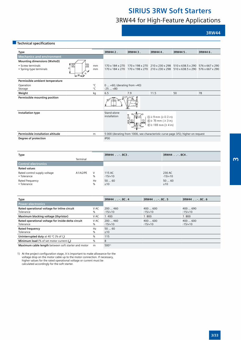
3RW44
Technical specifications
Type 3RW44 2 . 3RW44 3 . 3RW44 4 . 3RW44 5 . 3RW44 6 .
Mechanics and environmentMounting dimensions (WxHxD)
•Screwterminals•Spring-typeterminals
mmmm
170x184x270170x184x270
170x198x270170x198x270
210x230x298210x230x298
510x638.5x290510x638.5x290
576x667x290576x667x290
Permissible ambient temperature
OperationStorage
°C°C
0...+60;(deratingfrom+40)-25...+80
Weight kg 6.5 7.9 11.5 50 78
Permissible mounting position
Installation type Stand-alone installation
Permissible installation altitude m 5000(deratingfrom1000,seecharacteristiccurvepage3/5);higheronrequest
Degree of protection IP00
Type 3RW44 . . - . BC3 . 3RW44 . . - . BC4 .
Terminal
Control electronicsRated values
Ratedcontrolsupplyvoltage•Tolerance
A1/A2/PE V%
115AC-15/+10
230 AC-15/+10
Ratedfrequency•Tolerance
Hz%
50...60±10
50...60±10
Type 3RW44 . . - . BC . 4 3RW44 . . - . BC . 5 3RW44 . . - . BC . 6
Power electronicsRated operational voltage for inline circuitTolerance
VAC%
200 ... 460-15/+10
400 ... 600-15/+10
400 ... 690-15/+10
Maximum blocking voltage (thyristor) VAC 1 400 1 800 1 800
Rated operational voltage for inside-delta circuitTolerance
VAC%
200 ... 460-15/+10
400 ... 600-15/+10
400 ... 600-15/+10
Rated frequencyTolerance
Hz%
50...60±10
Uninterrupted dutyat40°C(%of Ie) % 115
Minimum load(%ofsetmotorcurrent IM) % 8
Maximum cable length betweensoftstarterandmotor m 5001)
1) Attheprojectconfigurationstage,itisimportanttomakeallowanceforthe voltagedroponthemotorcableuptothemotorconnection.Ifnecessary, higher values for the rated operational voltage or current must be calculatedaccordinglyforthesoftstarter.
3RW44 for High-Feature Applications
SIRIUS 3RW Soft Starters
3/33
3
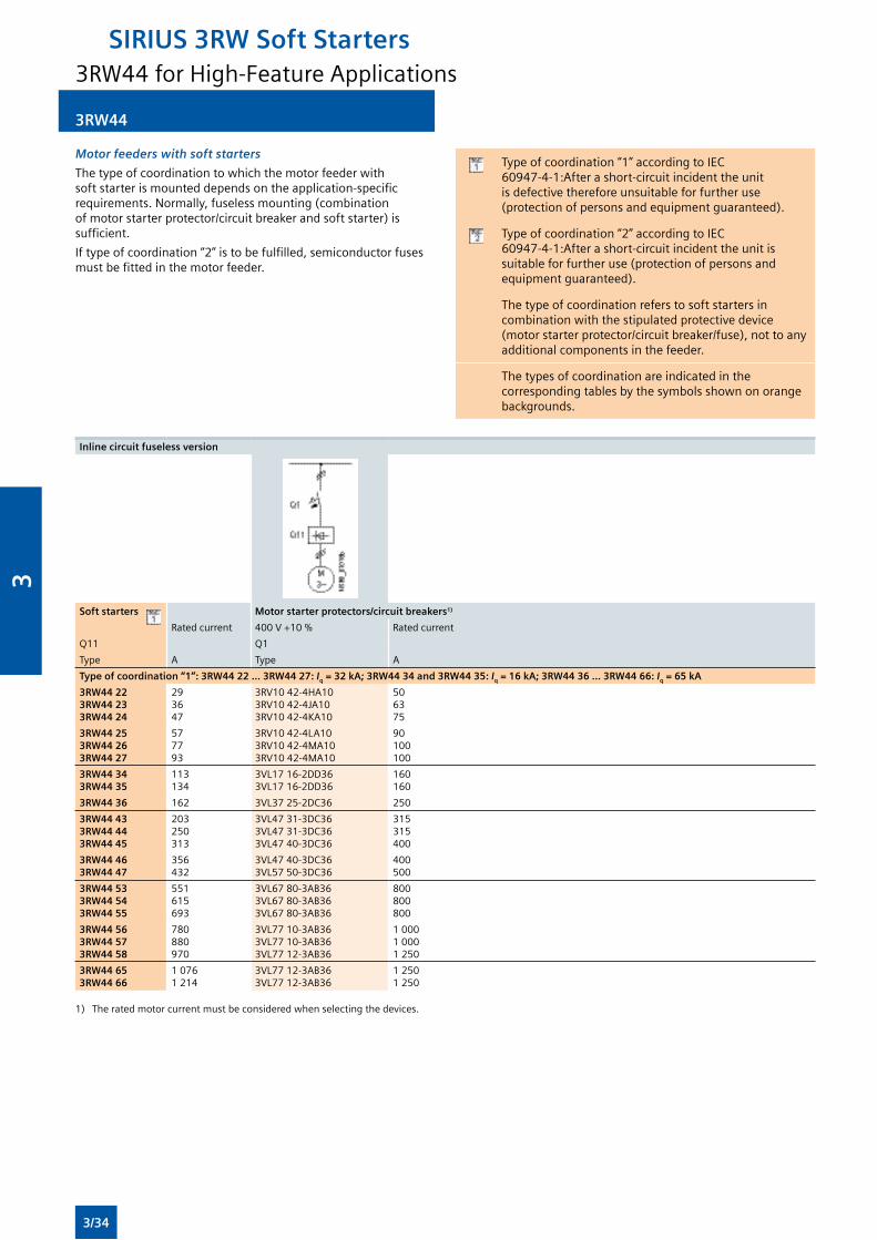
3RW44
Motor feeders with soft starters
Thetypeofcoordinationtowhichthemotorfeederwithsoftstarterismounteddependsontheapplication-specificrequirements.Normally,fuselessmounting(combinationofmotorstarterprotector/circuitbreakerandsoftstarter)issufficient.
Iftypeofcoordination“2”istobefulfilled,semiconductorfusesmustbefittedinthemotorfeeder.
Typeofcoordination“1”accordingtoIEC60947-4-1:Afterashort-circuitincidenttheunitis defective therefore unsuitable for further use (protectionofpersonsandequipmentguaranteed).
Typeofcoordination“2”accordingtoIEC60947-4-1:Afterashort-circuitincidenttheunitissuitableforfurtheruse(protectionofpersonsandequipmentguaranteed).
Thetypeofcoordinationreferstosoftstartersincombinationwiththestipulatedprotectivedevice(motorstarterprotector/circuitbreaker/fuse),nottoanyadditional components in the feeder.
Thetypesofcoordinationareindicatedinthecorrespondingtablesbythesymbolsshownonorangebackgrounds.
Inline circuit fuseless version
Soft starters Motor starter protectors/circuit breakers1)
Rated current 400V+10% Rated current
Q11 Q1
Type A Type A
Type of coordination “1”: 3RW44 22 ... 3RW44 27: Iq = 32 kA; 3RW44 34 and 3RW44 35: Iq = 16 kA; 3RW44 36 ... 3RW44 66: Iq = 65 kA
3RW44 223RW44 233RW44 24
293647
3RV1042-4HA103RV1042-4JA103RV1042-4KA10
506375
3RW44 253RW44 263RW44 27
577793
3RV1042-4LA103RV1042-4MA103RV1042-4MA10
90100100
3RW44 343RW44 35
113134
3VL1716-2DD363VL1716-2DD36
160160
3RW44 36 162 3VL3725-2DC36 250
3RW44 433RW44 443RW44 45
203250313
3VL4731-3DC363VL4731-3DC363VL4740-3DC36
315315400
3RW44 463RW44 47
356432
3VL4740-3DC363VL5750-3DC36
400500
3RW44 533RW44 543RW44 55
551615693
3VL6780-3AB363VL6780-3AB363VL6780-3AB36
800800800
3RW44 563RW44 573RW44 58
780880970
3VL7710-3AB363VL7710-3AB363VL7712-3AB36
1 0001 0001250
3RW44 653RW44 66
10761 214
3VL7712-3AB363VL7712-3AB36
12501250
1) Theratedmotorcurrentmustbeconsideredwhenselectingthedevices.
3RW44 for High-Feature Applications
SIRIUS 3RW Soft Starters
3/34
3
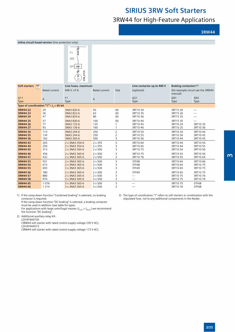
3RW44
Inline circuit fused version (lineprotectiononly)
Soft starters Line fuses, maximum Line contactor up to 400 V Braking contactors1)2)
Rated current 690V+5% Rated current Size (optional) (forexamplecircuitseethe3RW44manual)
Q11Type
F1Type
Q21Type
Q91 Type
Q92Type
A A
Type of coordination “1”3): Iq = 65 kA
3RW44 223RW44 233RW44 24
293647
3NA3 820-63NA3 822-63NA3 824-6
506380
000000
3RT10343RT10353RT1036
3RT15263RT15263RT1535
———
3RW44 253RW44 263RW44 27
577793
3NA3 830-63NA3 132-63NA3 136-6
100125160
0011
3RT10443RT10453RT1046
3RT15353RT10243RT1025
—3RT10353RT1036
3RW44 343RW44 353RW44 36
113134162
3NA3 244-63NA3 244-63NA3365-6
250250500
223
3RT10543RT10553RT1056
3RT10343RT10363RT1044
3RT10443RT10453RT1045
3RW44 433RW44 443RW44 45
203250313
2x3NA3354-62x3NA3354-62x3NA3365-6
2x3552x3552x500
333
3RT10643RT10653RT1075
3RT10443RT10443RT1054
3RT10543RT10553RT1056
3RW44 463RW44 47
356432
2x3NA3365-62x3NA3365-6
2x5002x500
33
3RT10753RT1076
3RT10543RT1055
3RT10563RT1064
3RW44 533RW44 543RW44 55
551615693
2x3NA3365-62x3NA3365-62x3NA3365-6
2x5002x5002x500
333
3TF683TF683TF69
3RT10643RT10643RT1065
3RT10663RT10753RT1075
3RW44 563RW44 573RW44 58
780880970
2x3NA3365-62x3NA3365-63x3NA3365-6
2x5002x5003x500
333
3TF69——
3RT10653RT10753RT1075
3RT10753RT10763RT1076
3RW44 653RW44 66
10761 214
3x3NA3365-63x3NA3365-6
3x5003x500
33
——
3RT10753RT1076
3TF683TF68
1) Iftheramp-downfunction“Combinedbraking”isselected,nobrakingcontactor is required. Iftheramp-downfunction“DCbraking”isselected,abrakingcontactormustbeusedinaddition(seetablefortype). Forapplicationswithlargecentrifugalmasses(JLoad > JMotor)werecommendthefunction“DCbraking”.
2) AdditionalauxiliaryrelayK4: LZX:RT4A4T30 (3RW44softstarterwithratedcontrolsupplyvoltage230VAC), LZX:RT4A4S15 (3RW44softstarterwithratedcontrolsupplyvoltage115VAC).
3) Thetypeofcoordination“1”referstosoftstartersincombinationwiththestipulatedfuse,nottoanyadditionalcomponentsinthefeeder.
3RW44 for High-Feature Applications
SIRIUS 3RW Soft Starters
3/35
3
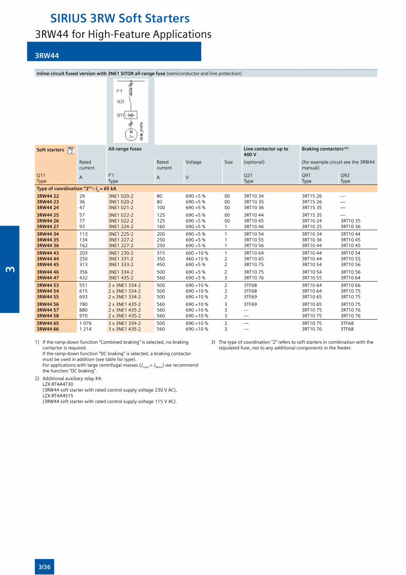
3RW44
Inline circuit fused version with 3NE1 SITOR all-range fuse(semiconductorandlineprotection)
Soft starters All-range fuses Line contactor up to 400 V
Braking contactors1)2)
Rated current
Rated current
Voltage Size (optional) (forexamplecircuitseethe3RW44manual)
Q11Type
F’1Type
Q21Type
Q91Type
Q92Type
A A V
Type of coordination “2”3): Iq = 65 kA
3RW44 223RW44 233RW44 24
293647
3NE1020-23NE1020-23NE1021-2
8080100
690+5%690+5%690+5%
000000
3RT10343RT10353RT1036
3RT15263RT15263RT1535
———
3RW44 253RW44 263RW44 27
577793
3NE1022-23NE1022-23NE1224-2
125125160
690+5%690+5%690+5%
00001
3RT10443RT10453RT1046
3RT15353RT10243RT1025
—3RT10353RT1036
3RW44 343RW44 353RW44 36
113134162
3NE1225-23NE1227-23NE1227-2
200250250
690+5%690+5%690+5%
111
3RT10543RT10553RT1056
3RT10343RT10363RT1044
3RT10443RT10453RT1045
3RW44 433RW44 443RW44 45
203250313
3NE1230-23NE1331-23NE1333-2
315350450
600+10%460+10%690+5%
122
3RT10643RT10653RT1075
3RT10443RT10443RT1054
3RT10543RT10553RT1056
3RW44 463RW44 47
356432
3NE1334-23NE1435-2
500560
690+5%690+5%
23
3RT10753RT1076
3RT10543RT1055
3RT10563RT1064
3RW44 533RW44 543RW44 55
551615693
2x3NE1334-22x3NE1334-22x3NE1334-2
500500500
690+10%690+10%690+10%
222
3TF683TF683TF69
3RT10643RT10643RT1065
3RT10663RT10753RT1075
3RW44 563RW44 573RW44 58
780880970
2x3NE1435-22x3NE1435-22x3NE1435-2
560560560
690+10%690+10%690+10%
333
3TF69——
3RT10653RT10753RT1075
3RT10753RT10763RT1076
3RW44 653RW44 66
10761 214
3x3NE1334-23x3NE1435-2
500560
690+10%690+10%
23
——
3RT10753RT1076
3TF683TF68
1) Iftheramp-downfunction“Combinedbraking”isselected,nobrakingcontactor is required. Iftheramp-downfunction“DCbraking”isselected,abrakingcontactormustbeusedinaddition(seetablefortype). Forapplicationswithlargecentrifugalmasses(JLoad > JMotor)werecommendthefunction“DCbraking”.
2) AdditionalauxiliaryrelayK4: LZX:RT4A4T30 (3RW44softstarterwithratedcontrolsupplyvoltage230VAC), LZX:RT4A4S15 (3RW44softstarterwithratedcontrolsupplyvoltage115VAC).
3) Thetypeofcoordination“2”referstosoftstartersincombinationwiththestipulatedfuse,nottoanyadditionalcomponentsinthefeeder.
3RW44 for High-Feature Applications
SIRIUS 3RW Soft Starters
3/36
3
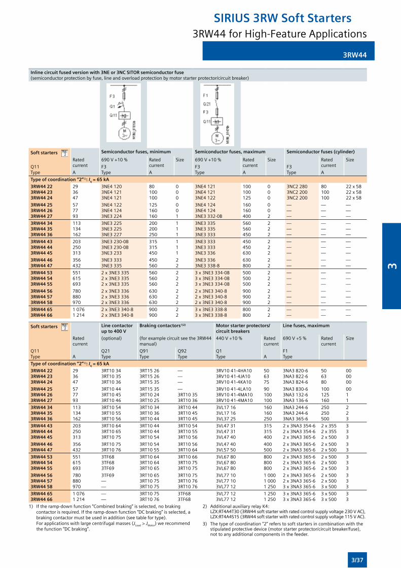
3RW44
Inline circuit fused version with 3NE or 3NC SITOR semiconductor fuse (semiconductorprotectionbyfuse,lineandoverloadprotectionbymotorstarterprotector/circuitbreaker)
Soft starters Semiconductor fuses, minimum Semiconductor fuses, maximum Semiconductor fuses (cylinder)
Rated current
690V+10% Rated current
Size 690V+10% Rated current
Size Rated current
Size
Q11Type
F3Type
F3Type
F3TypeA A A A
Type of coordination “2”3): Iq = 65 kA
3RW44 223RW44 233RW44 24
293647
3NE41203NE41213NE4121
80100100
000
3NE41213NE41213NE4122
100100125
000
3NC2 2803NC2 2003NC2 200
80100100
22x5822x5822x58
3RW44 253RW44 263RW44 27
577793
3NE41223NE41243NE3224
125160160
001
3NE41243NE41243NE3332-0B
160160400
002
———
———
———
3RW44 343RW44 353RW44 36
113134162
3NE32253NE32253NE3227
200200250
111
3NE33353NE33353NE3333
560560450
222
———
———
———
3RW44 433RW44 443RW44 45
203250313
3NE3230-0B3NE3230-0B3NE3233
315315450
111
3NE33333NE33333NE3336
450450630
222
———
———
———
3RW44 463RW44 47
356432
3NE33333NE3335
450560
22
3NE33363NE3338-8
630800
22
——
——
——
3RW44 533RW44 543RW44 55
551615693
2x3NE33352x3NE33352x3NE3335
560560560
222
3x3NE3334-0B3x3NE3334-0B3x3NE3334-0B
500500500
222
———
———
———
3RW44 563RW44 573RW44 58
780880970
2x3NE33362x3NE33362x3NE3336
630630630
222
2x3NE3340-82x3NE3340-82x3NE3340-8
900900900
222
———
———
———
3RW44 653RW44 66
10761 214
2x3NE3340-82x3NE3340-8
900900
22
3x3NE3338-83x3NE3338-8
800800
22
——
——
——
Soft starters Line contactor up to 400 V
Braking contactors1)2) Motor starter protectors/circuit breakers
Line fuses, maximum
Rated current
(optional) (forexamplecircuitseethe3RW44manual)
440V+10% Rated current
690V+5% Rated current
Size
Q11Type A
Q21Type
Q91Type
Q92Type
Q1Type A
F1Type
Type of coordination “2”3): Iq = 65 kA
3RW44 223RW44 233RW44 24
293647
3RT10343RT10353RT1036
3RT15263RT15263RT1535
———
3RV1041-4HA103RV1041-4JA103RV1041-4KA10
506375
3NA3 820-63NA3 822-63NA3 824-6
506380
000000
3RW44 253RW44 263RW44 27
577793
3RT10443RT10453RT1046
3RT15353RT10243RT1025
—3RT10353RT1036
3RV1041-4LA103RV1041-4MA103RV1041-4MA10
90100100
3NA3 830-63NA3 132-63NA3 136-6
100125160
0011
3RW44 343RW44 353RW44 36
113134162
3RT10543RT10553RT1056
3RT10343RT10363RT1044
3RT10443RT10453RT1045
3VL17163VL17163VL3725
160160250
3NA3 244-63NA3 244-63NA3365-6
250250500
223
3RW44 433RW44 443RW44 45
203250313
3RT10643RT10653RT1075
3RT10443RT10443RT1054
3RT10543RT10553RT1056
3VL47313VL47313VL4740
315315400
2x3NA3354-62x3NA3354-62x3NA3365-6
2x3552x3552x500
333
3RW44 463RW44 47
356432
3RT10753RT1076
3RT10543RT1055
3RT10563RT1064
3VL47403VL5750
400500
2x3NA3365-62x3NA3365-6
2x5002x500
33
3RW44 533RW44 543RW44 55
551615693
3TF683TF683TF69
3RT10643RT10643RT1065
3RT10663RT10753RT1075
3VL67803VL67803VL6780
800800800
2x3NA3365-62x3NA3365-62x3NA3365-6
2x5002x5002x500
333
3RW44 563RW44 573RW44 58
780880970
3TF69——
3RT10653RT10753RT1075
3RT10753RT10763RT1076
3VL77103VL77103VL7712
1 0001 0001250
2x3NA3365-62x3NA3365-63x3NA3365-6
2x5002x5003x500
333
3RW44 653RW44 66
10761 214
——
3RT10753RT1076
3TF683TF68
3VL77123VL7712
12501250
3x3NA3365-63x3NA3365-6
3x5003x500
33
1) Iftheramp-downfunction“Combinedbraking”isselected,nobrakingcontactorisrequired.Iftheramp-downfunction“DCbraking”isselected,abrakingcontactormustbeusedinaddition(seetablefortype). Forapplicationswithlargecentrifugalmasses(JLoad > JMotor)werecommendthefunction“DCbraking”.
2) AdditionalauxiliaryrelayK4: LZX:RT4A4T30(3RW44softstarterwithratedcontrolsupplyvoltage230VAC), LZX:RT4A4S15(3RW44softstarterwithratedcontrolsupplyvoltage115VAC).
3) Thetypeofcoordination“2”referstosoftstartersincombinationwiththestipulatedprotectivedevice(motorstarterprotector/circuitbreaker/fuse),nottoanyadditionalcomponentsinthefeeder.
3RW44 for High-Feature Applications
SIRIUS 3RW Soft Starters
3/37
3
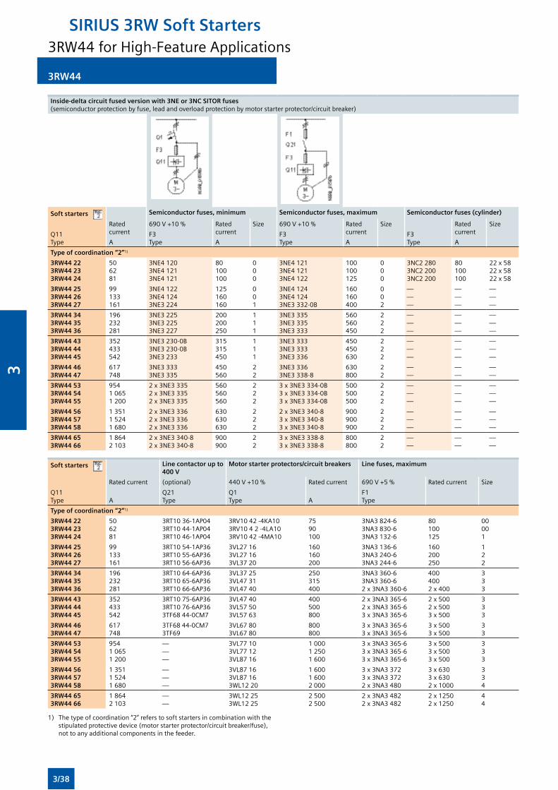
3RW44
Inside-delta circuit fused version with 3NE or 3NC SITOR fuses (semiconductorprotectionbyfuse,leadandoverloadprotectionbymotorstarterprotector/circuitbreaker)
Soft starters Semiconductor fuses, minimum Semiconductor fuses, maximum Semiconductor fuses (cylinder)
Rated current
690V+10% Rated current
Size 690V+10% Rated current
Size Rated current
Size
Q11Type
F3Type
F3Type
F3TypeA A A A
Type of coordination “2”1)
3RW44 223RW44 233RW44 24
506281
3NE41203NE41213NE4121
80100100
000
3NE41213NE41213NE4122
100100125
000
3NC2 2803NC2 2003NC2 200
80100100
22x5822x5822x58
3RW44 253RW44 263RW44 27
99133161
3NE41223NE41243NE3224
125160160
001
3NE41243NE41243NE3332-0B
160160400
002
———
———
———
3RW44 343RW44 353RW44 36
196232281
3NE32253NE32253NE3227
200200250
111
3NE33353NE33353NE3333
560560450
222
———
———
———
3RW44 433RW44 443RW44 45
352433542
3NE3230-0B3NE3230-0B3NE3233
315315450
111
3NE33333NE33333NE3336
450450630
222
———
———
———
3RW44 463RW44 47
617748
3NE33333NE3335
450560
22
3NE33363NE3338-8
630800
22
——
——
——
3RW44 533RW44 543RW44 55
95410651 200
2x3NE33352x3NE33352x3NE3335
560560560
222
3x3NE3334-0B3x3NE3334-0B3x3NE3334-0B
500500500
222
———
———
———
3RW44 563RW44 573RW44 58
135115241 680
2x3NE33362x3NE33362x3NE3336
630630630
222
2x3NE3340-83x3NE3340-83x3NE3340-8
900900900
222
———
———
———
3RW44 653RW44 66
1 8642 103
2x3NE3340-82x3NE3340-8
900900
22
3x3NE3338-83x3NE3338-8
800800
22
——
——
——
Soft starters Line contactor up to 400 V
Motor starter protectors/circuit breakers Line fuses, maximum
Rated current (optional) 440V+10% Rated current 690V+5% Rated current Size
Q11Type A
Q21Type
Q1Type A
F1Type
Type of coordination “2”1)
3RW44 223RW44 233RW44 24
506281
3RT1036-1AP043RT1044-1AP043RT1046-1AP04
3RV1042-4KA103RV1042-4LA103RV1042-4MA10
7590100
3NA3 824-63NA3 830-63NA3 132-6
80100125
00001
3RW44 253RW44 263RW44 27
99133161
3RT1054-1AP363RT1055-6AP363RT1056-6AP36
3VL27163VL27163VL3720
160160200
3NA3 136-63NA3 240-63NA3 244-6
160200250
122
3RW44 343RW44 353RW44 36
196232281
3RT1064-6AP363RT1065-6AP363RT1066-6AP36
3VL37253VL47313VL4740
250315400
3NA3 360-63NA3 360-62x3NA3360-6
4004002x400
333
3RW44 433RW44 443RW44 45
352433542
3RT1075-6AP363RT1076-6AP363TF6844-0CM7
3VL47403VL57503VL5763
400500800
2x3NA3365-62x3NA3365-63x3NA3365-6
2x5002x5003x500
333
3RW44 463RW44 47
617748
3TF6844-0CM73TF69
3VL67803VL6780
800800
3x3NA3365-63x3NA3365-6
3x5003x500
33
3RW44 533RW44 543RW44 55
95410651 200
———
3VL77103VL77123VL8716
1 00012501 600
3x3NA3365-63x3NA3365-63x3NA3365-6
3x5003x5003x500
333
3RW44 563RW44 573RW44 58
135115241 680
———
3VL87163VL87163WL1220
1 6001 6002 000
3x3NA33723x3NA33722x3NA3480
3x6303x6302x1000
334
3RW44 653RW44 66
1 8642 103
——
3WL12253WL1225
25002500
2x3NA34822x3NA3482
2x12502x1250
44
1) Thetypeofcoordination“2”referstosoftstartersincombinationwiththe stipulatedprotectivedevice(motorstarterprotector/circuitbreaker/fuse), nottoanyadditionalcomponentsinthefeeder.
3RW44 for High-Feature Applications
SIRIUS 3RW Soft Starters
3/38
3
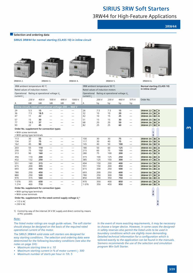
3RW44
Selection and ordering data
SIRIUS 3RW44 for normal starting (CLASS 10) in inline circuit
3RW442. 3RW443. 3RW444. 3RW445. 3RW446.
3RW ambient temperature 40 °C 3RWambienttemperature50°C Normal starting (CLASS 10) in inline circuitRated values of induction motors Rated values of induction motors
Operational current Ie
Rating at operational voltage Ue Operational current Ie
Rating at operational voltage Ue
230V 400V 500V 690V 1000V 200V 230V 460V 575V Order No.
A kW kW kW kW kW A hp hp hp hp
Inline circuit, rated operational voltage 200 ... 460 V293647
5.57.511
1518.522
———
———
———
263242
7.51010
7.51015
152025
———
3RW44 22- BC 43RW44 23- BC 43RW44 24- BC 4
577793
1518.522
303745
———
———
———
516882
152025
152025
305060
———
3RW44 25- BC 43RW44 26- BC 43RW44 27- BC 4
Order No. supplement for connection types
•Withscrewterminals•Withspring-typeterminals
1 3
113134162
303745
557590
———
———
———
100117145
303040
304050
7575100
———
3RW44 34- BC 43RW44 35- BC 43RW44 36- BC 4
203250313
557590
110132160
———
———
———
180215280
506075
6075100
125150200
———
3RW44 43- BC 43RW44 44- BC 43RW44 45- BC 4
356432
110132
200250
——
——
——
315385
100125
125150
250300
——
3RW44 46- BC 43RW44 47- BC 4
551615693
160200200
315355400
———
———
———
494551615
150150200
200200250
400450500
———
3RW44 53- BC 43RW44 54- BC 43RW44 55- BC 4
780880970
250250315
450500560
———
———
———
693780850
200250300
250300350
600700750
———
3RW44 56- BC 43RW44 57- BC 43RW44 58- BC 4
10761 214
355400
630710
——
——
——
9701076
350350
400450
850950
——
3RW44 65- BC 43RW44 66- BC 4
Order No. supplement for connection types
•Withspring-typeterminals•Withscrewterminals
2 6
Order No. supplement for the rated control supply voltage Us1)
•115VAC•230VAC
3 4
1) Controlbywayoftheinternal24VDCsupplyanddirectcontrolbymeans ofPLCpossible.
Note:
The listed motor ratings are rough guide values. The soft starter should always be designed on the basis of the required rated operational current of the motor.
The SIRIUS 3RW44 solid-state soft starters are designed for easy starting conditions. The selection and ordering data were determined for the following boundary conditions (see also the notes on page 3/4):• Maximum starting time in s: 10• Maximum starting current in % of motor current Ie: 300• Maximum number of starts per hour in 1/h: 5
In the event of more exacting requirements, it may be necessary to choose a larger device. However, in some cases the designed-in safety reserves also permit the listed units to be used in boundary conditions which are slightly more demanding. Detailed technical information for a configuration which is tailored exactly to the application can be found in the manuals. Siemens recommends the use of the selection and simulation program Win-Soft Starter.
3RW44 for High-Feature Applications
SIRIUS 3RW Soft Starters
3/39
3
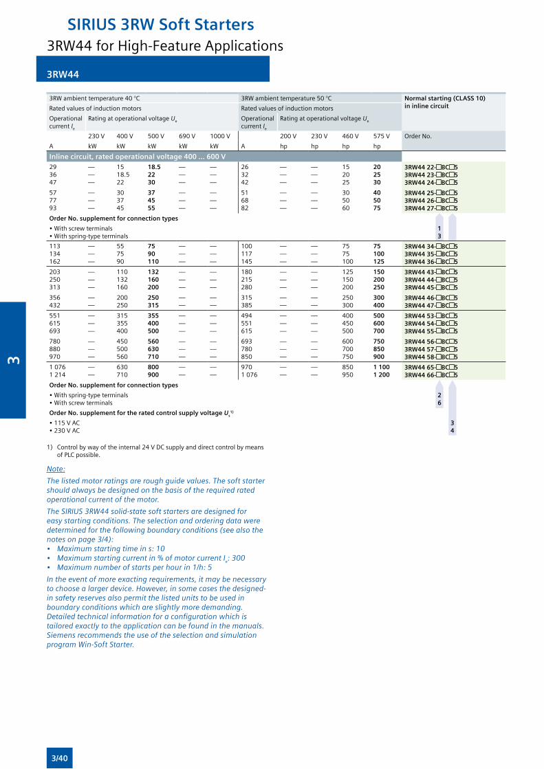
3RW44
1) Controlbywayoftheinternal24VDCsupplyanddirectcontrolbymeansofPLCpossible.
Note:
The listed motor ratings are rough guide values. The soft starter should always be designed on the basis of the required rated operational current of the motor.
The SIRIUS 3RW44 solid-state soft starters are designed for easy starting conditions. The selection and ordering data were determined for the following boundary conditions (see also the notes on page 3/4):• Maximum starting time in s: 10• Maximum starting current in % of motor current Ie: 300• Maximum number of starts per hour in 1/h: 5
In the event of more exacting requirements, it may be necessary to choose a larger device. However, in some cases the designed-in safety reserves also permit the listed units to be used in boundary conditions which are slightly more demanding. Detailed technical information for a configuration which is tailored exactly to the application can be found in the manuals. Siemens recommends the use of the selection and simulation program Win-Soft Starter.
3RW ambient temperature 40 °C 3RWambienttemperature50°C Normal starting (CLASS 10) in inline circuitRated values of induction motors Rated values of induction motors
Operational current Ie
Rating at operational voltage Ue Operational current Ie
Rating at operational voltage Ue
230V 400V 500V 690V 1000V 200V 230V 460V 575V Order No.
A kW kW kW kW kW A hp hp hp hp
Inline circuit, rated operational voltage 400 ... 600 V293647
———
1518.522
18.52230
———
———
263242
———
———
152025
202530
3RW44 22- BC 53RW44 23- BC 53RW44 24- BC 5
577793
———
303745
374555
———
———
516882
———
———
305060
405075
3RW44 25- BC 53RW44 26- BC 53RW44 27- BC 5
Order No. supplement for connection types
•Withscrewterminals•Withspring-typeterminals
1 3
113134162
———
557590
7590110
———
———
100117145
———
———
7575100
75100125
3RW44 34- BC 53RW44 35- BC 53RW44 36- BC 5
203250313
———
110132160
132160200
———
———
180215280
———
———
125150200
150200250
3RW44 43- BC 53RW44 44- BC 53RW44 45- BC 5
356432
——
200250
250315
——
——
315385
——
——
250300
300400
3RW44 46- BC 53RW44 47- BC 5
551615693
———
315355400
355400500
———
———
494551615
———
———
400450500
500600700
3RW44 53- BC 53RW44 54- BC 53RW44 55- BC 5
780880970
———
450500560
560630710
———
———
693780850
———
———
600700750
750850900
3RW44 56- BC 53RW44 57- BC 53RW44 58- BC 5
10761 214
——
630710
800900
——
——
9701076
——
——
850950
1 1001 200
3RW44 65- BC 53RW44 66- BC 5
Order No. supplement for connection types
•Withspring-typeterminals•Withscrewterminals
2 6
Order No. supplement for the rated control supply voltage Us1)
•115VAC•230VAC
3 4
3RW44 for High-Feature Applications
SIRIUS 3RW Soft Starters
3/40
3
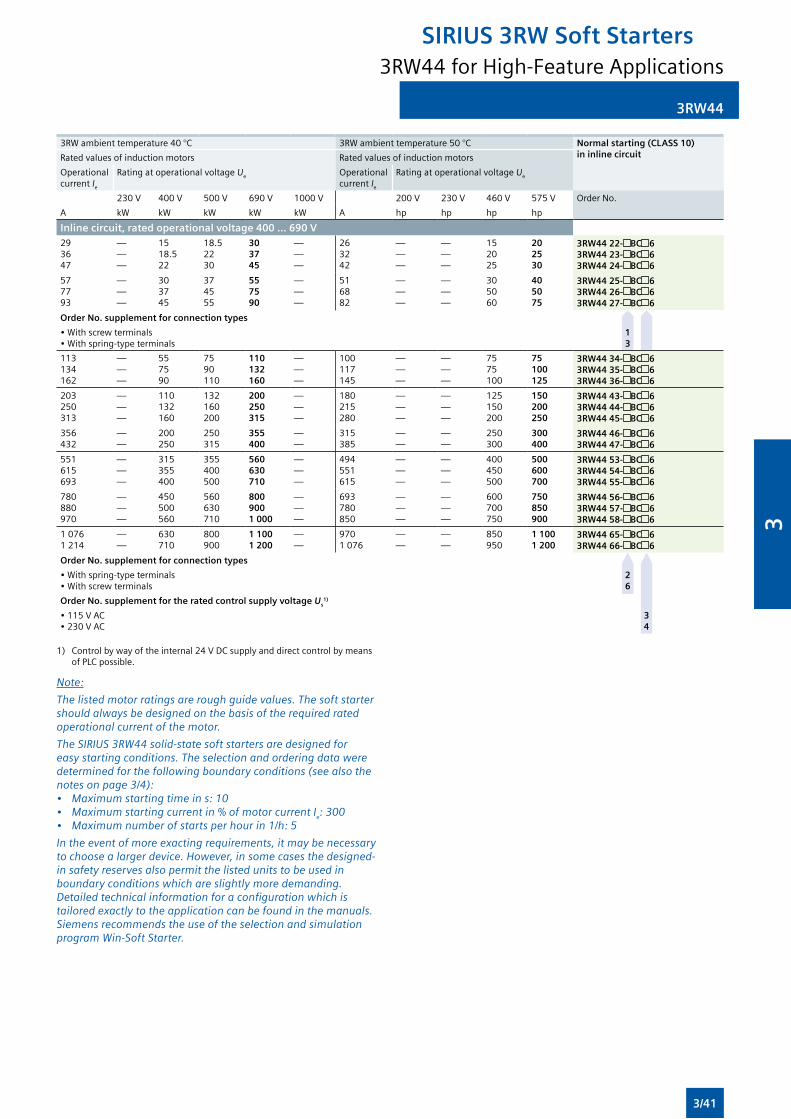
3RW44
3RW ambient temperature 40 °C 3RWambienttemperature50°C Normal starting (CLASS 10) in inline circuitRated values of induction motors Rated values of induction motors
Operational current Ie
Rating at operational voltage Ue Operational current Ie
Rating at operational voltage Ue
230V 400V 500V 690V 1000V 200V 230V 460V 575V Order No.
A kW kW kW kW kW A hp hp hp hp
Inline circuit, rated operational voltage 400 ... 690 V293647
———
1518.522
18.52230
303745
———
263242
———
———
152025
202530
3RW44 22- BC 63RW44 23- BC 63RW44 24- BC 6
577793
———
303745
374555
557590
———
516882
———
———
305060
405075
3RW44 25- BC 63RW44 26- BC 63RW44 27- BC 6
Order No. supplement for connection types
•Withscrewterminals•Withspring-typeterminals
1 3
113134162
———
557590
7590110
110132160
———
100117145
———
———
7575100
75100125
3RW44 34- BC 63RW44 35- BC 63RW44 36- BC 6
203250313
———
110132160
132160200
200250315
———
180215280
———
———
125150200
150200250
3RW44 43- BC 63RW44 44- BC 63RW44 45- BC 6
356432
——
200250
250315
355400
——
315385
——
——
250300
300400
3RW44 46- BC 63RW44 47- BC 6
551615693
———
315355400
355400500
560630710
———
494551615
———
———
400450500
500600700
3RW44 53- BC 63RW44 54- BC 63RW44 55- BC 6
780880970
———
450500560
560630710
8009001 000
———
693780850
———
———
600700750
750850900
3RW44 56- BC 63RW44 57- BC 63RW44 58- BC 6
10761 214
——
630710
800900
1 1001 200
——
9701076
——
——
850950
1 1001 200
3RW44 65- BC 63RW44 66- BC 6
Order No. supplement for connection types
•Withspring-typeterminals•Withscrewterminals
2 6
Order No. supplement for the rated control supply voltage Us1)
•115VAC•230VAC
3 4
1) Controlbywayoftheinternal24VDCsupplyanddirectcontrolbymeansofPLCpossible.
Note:
The listed motor ratings are rough guide values. The soft starter should always be designed on the basis of the required rated operational current of the motor.
The SIRIUS 3RW44 solid-state soft starters are designed for easy starting conditions. The selection and ordering data were determined for the following boundary conditions (see also the notes on page 3/4):• Maximum starting time in s: 10• Maximum starting current in % of motor current Ie: 300• Maximum number of starts per hour in 1/h: 5
In the event of more exacting requirements, it may be necessary to choose a larger device. However, in some cases the designed-in safety reserves also permit the listed units to be used in boundary conditions which are slightly more demanding. Detailed technical information for a configuration which is tailored exactly to the application can be found in the manuals. Siemens recommends the use of the selection and simulation program Win-Soft Starter.
3RW44 for High-Feature Applications
SIRIUS 3RW Soft Starters
3/41
3
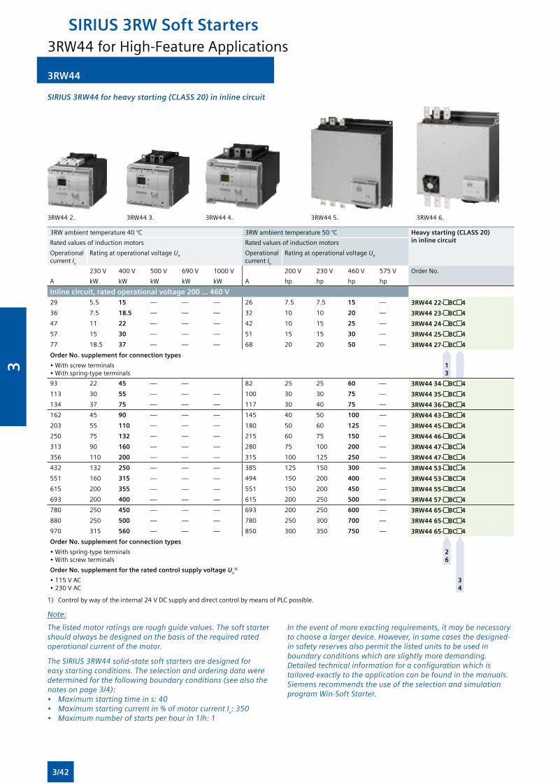
3RW44
SIRIUS 3RW44 for heavy starting (CLASS 20) in inline circuit
3RW442. 3RW443. 3RW444. 3RW445. 3RW446.
3RW ambient temperature 40 °C 3RWambienttemperature50°C Heavy starting (CLASS 20) in inline circuitRated values of induction motors Rated values of induction motors
Operational current Ie
Rating at operational voltage Ue Operational current Ie
Rating at operational voltage Ue
230V 400V 500V 690V 1000V 200V 230V 460V 575V Order No.
A kW kW kW kW kW A hp hp hp hp
Inline circuit, rated operational voltage 200 ... 460 V29 5.5 15 — — — 26 7.5 7.5 15 — 3RW44 22- BC 4
36 7.5 18.5 — — — 32 10 10 20 — 3RW44 23- BC 4
47 11 22 — — — 42 10 15 25 — 3RW44 24- BC 4
57 15 30 — — — 51 15 15 30 — 3RW44 25- BC 4
77 18.5 37 — — — 68 20 20 50 — 3RW44 27- BC 4
Order No. supplement for connection types
•Withscrewterminals•Withspring-typeterminals
1 3
93 22 45 — — 82 25 25 60 — 3RW44 34- BC 4
113 30 55 — — — 100 30 30 75 — 3RW44 35- BC 4
134 37 75 — — — 117 30 40 75 — 3RW44 36- BC 4
162 45 90 — — — 145 40 50 100 — 3RW44 43- BC 4
203 55 110 — — — 180 50 60 125 — 3RW44 45- BC 4
250 75 132 — — — 215 60 75 150 — 3RW44 46- BC 4
313 90 160 — — — 280 75 100 200 — 3RW44 47- BC 4
356 110 200 — — — 315 100 125 250 — 3RW44 47- BC 4
432 132 250 — — — 385 125 150 300 — 3RW44 53- BC 4
551 160 315 — — — 494 150 200 400 — 3RW44 53- BC 4
615 200 355 — — — 551 150 200 450 — 3RW44 55- BC 4
693 200 400 — — — 615 200 250 500 — 3RW44 57- BC 4
780 250 450 — — — 693 200 250 600 — 3RW44 65- BC 4
880 250 500 — — — 780 250 300 700 — 3RW44 65- BC 4
970 315 560 — — — 850 300 350 750 — 3RW44 65- BC 4
Order No. supplement for connection types
•Withspring-typeterminals•Withscrewterminals
2 6
Order No. supplement for the rated control supply voltage Us1)
•115VAC•230VAC
3 4
1) Controlbywayoftheinternal24VDCsupplyanddirectcontrolbymeansofPLCpossible.
Note:
The listed motor ratings are rough guide values. The soft starter should always be designed on the basis of the required rated operational current of the motor.
The SIRIUS 3RW44 solid-state soft starters are designed for easy starting conditions. The selection and ordering data were determined for the following boundary conditions (see also the notes on page 3/4):• Maximum starting time in s: 40• Maximum starting current in % of motor current Ie: 350• Maximum number of starts per hour in 1/h: 1
In the event of more exacting requirements, it may be necessary to choose a larger device. However, in some cases the designed-in safety reserves also permit the listed units to be used in boundary conditions which are slightly more demanding. Detailed technical information for a configuration which is tailored exactly to the application can be found in the manuals. Siemens recommends the use of the selection and simulation program Win-Soft Starter.
3RW44 for High-Feature Applications
SIRIUS 3RW Soft Starters
3/42
3
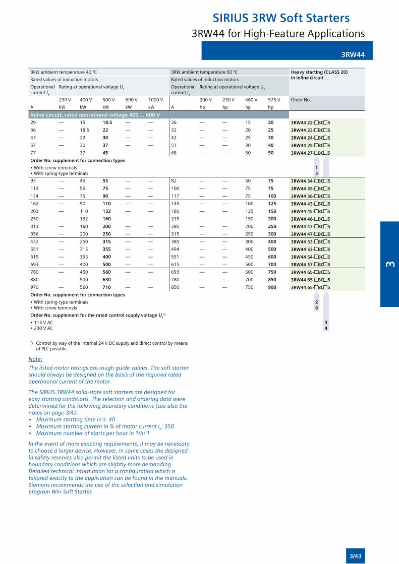
3RW44
3RW ambient temperature 40 °C 3RWambienttemperature50°C Heavy starting (CLASS 20) in inline circuitRated values of induction motors Rated values of induction motors
Operational current Ie
Rating at operational voltage Ue Operational current Ie
Rating at operational voltage Ue
230V 400V 500V 690V 1000V 200V 230V 460V 575V Order No.
A kW kW kW kW kW A hp hp hp hp
Inline circuit, rated operational voltage 400 ... 600 V29 — 15 18.5 — — 26 — — 15 20 3RW44 22- BC 5
36 — 18.5 22 — — 32 — — 20 25 3RW44 23- BC 5
47 — 22 30 — — 42 — — 25 30 3RW44 24- BC 5
57 — 30 37 — — 51 — — 30 40 3RW44 25- BC 5
77 — 37 45 — — 68 — — 50 50 3RW44 27- BC 5
Order No. supplement for connection types
•Withscrewterminals•Withspring-typeterminals
1 3
93 — 45 55 — — 82 — — 60 75 3RW44 34- BC 5
113 — 55 75 — — 100 — — 75 75 3RW44 35- BC 5
134 — 75 90 — — 117 — — 75 100 3RW44 36- BC 5
162 — 90 110 — — 145 — — 100 125 3RW44 43- BC 5
203 — 110 132 — — 180 — — 125 150 3RW44 45- BC 5
250 — 132 160 — — 215 — — 150 200 3RW44 46- BC 5
313 — 160 200 — — 280 — — 200 250 3RW44 47- BC 5
356 — 200 250 — — 315 — — 250 300 3RW44 47- BC 5
432 — 250 315 — — 385 — — 300 400 3RW44 53- BC 5
551 — 315 355 — — 494 — — 400 500 3RW44 53- BC 5
615 — 355 400 — — 551 — — 450 600 3RW44 54- BC 5
693 — 400 500 — — 615 — — 500 700 3RW44 57- BC 5
780 — 450 560 — — 693 — — 600 750 3RW44 65- BC 5
880 — 500 630 — — 780 — — 700 850 3RW44 65- BC 5
970 — 560 710 — — 850 — — 750 900 3RW44 65- BC 5
Order No. supplement for connection types
•Withspring-typeterminals•Withscrewterminals
2 6
Order No. supplement for the rated control supply voltage Us1)
•115VAC•230VAC
3 4
1) Controlbywayoftheinternal24VDCsupplyanddirectcontrolbymeansofPLCpossible.
Note:
The listed motor ratings are rough guide values. The soft starter should always be designed on the basis of the required rated operational current of the motor.
The SIRIUS 3RW44 solid-state soft starters are designed for easy starting conditions. The selection and ordering data were determined for the following boundary conditions (see also the notes on page 3/4):• Maximum starting time in s: 40• Maximum starting current in % of motor current Ie: 350• Maximum number of starts per hour in 1/h: 1
In the event of more exacting requirements, it may be necessary to choose a larger device. However, in some cases the designed-in safety reserves also permit the listed units to be used in boundary conditions which are slightly more demanding. Detailed technical information for a configuration which is tailored exactly to the application can be found in the manuals. Siemens recommends the use of the selection and simulation program Win-Soft Starter.
3RW44 for High-Feature Applications
SIRIUS 3RW Soft Starters
3/43
3
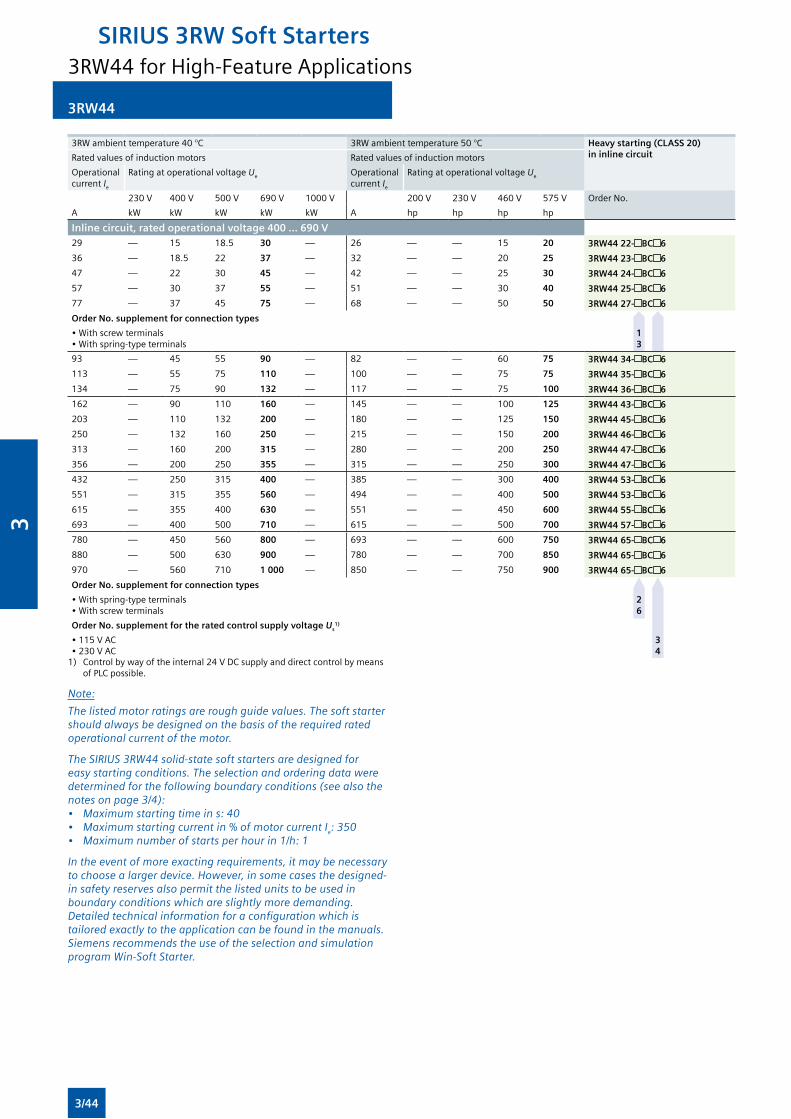
3RW44
3RW ambient temperature 40 °C 3RWambienttemperature50°C Heavy starting (CLASS 20) in inline circuitRated values of induction motors Rated values of induction motors
Operational current Ie
Rating at operational voltage Ue Operational current Ie
Rating at operational voltage Ue
230V 400V 500V 690V 1000V 200V 230V 460V 575V Order No.
A kW kW kW kW kW A hp hp hp hp
Inline circuit, rated operational voltage 400 ... 690 V29 — 15 18.5 30 — 26 — — 15 20 3RW44 22- BC 6
36 — 18.5 22 37 — 32 — — 20 25 3RW44 23- BC 6
47 — 22 30 45 — 42 — — 25 30 3RW44 24- BC 6
57 — 30 37 55 — 51 — — 30 40 3RW44 25- BC 6
77 — 37 45 75 — 68 — — 50 50 3RW44 27- BC 6
Order No. supplement for connection types
•Withscrewterminals•Withspring-typeterminals
1 3
93 — 45 55 90 — 82 — — 60 75 3RW44 34- BC 6
113 — 55 75 110 — 100 — — 75 75 3RW44 35- BC 6
134 — 75 90 132 — 117 — — 75 100 3RW44 36- BC 6
162 — 90 110 160 — 145 — — 100 125 3RW44 43- BC 6
203 — 110 132 200 — 180 — — 125 150 3RW44 45- BC 6
250 — 132 160 250 — 215 — — 150 200 3RW44 46- BC 6
313 — 160 200 315 — 280 — — 200 250 3RW44 47- BC 6
356 — 200 250 355 — 315 — — 250 300 3RW44 47- BC 6
432 — 250 315 400 — 385 — — 300 400 3RW44 53- BC 6
551 — 315 355 560 — 494 — — 400 500 3RW44 53- BC 6
615 — 355 400 630 — 551 — — 450 600 3RW44 55- BC 6
693 — 400 500 710 — 615 — — 500 700 3RW44 57- BC 6
780 — 450 560 800 — 693 — — 600 750 3RW44 65- BC 6
880 — 500 630 900 — 780 — — 700 850 3RW44 65- BC 6
970 — 560 710 1 000 — 850 — — 750 900 3RW44 65- BC 6
Order No. supplement for connection types
•Withspring-typeterminals•Withscrewterminals
2 6
Order No. supplement for the rated control supply voltage Us1)
•115VAC•230VAC
3 4
1) Controlbywayoftheinternal24VDCsupplyanddirectcontrolbymeansofPLCpossible.
Note:
The listed motor ratings are rough guide values. The soft starter should always be designed on the basis of the required rated operational current of the motor.
The SIRIUS 3RW44 solid-state soft starters are designed for easy starting conditions. The selection and ordering data were determined for the following boundary conditions (see also the notes on page 3/4):• Maximum starting time in s: 40• Maximum starting current in % of motor current Ie: 350• Maximum number of starts per hour in 1/h: 1
In the event of more exacting requirements, it may be necessary to choose a larger device. However, in some cases the designed-in safety reserves also permit the listed units to be used in boundary conditions which are slightly more demanding. Detailed technical information for a configuration which is tailored exactly to the application can be found in the manuals. Siemens recommends the use of the selection and simulation program Win-Soft Starter.
3RW44 for High-Feature Applications
SIRIUS 3RW Soft Starters
3/44
3
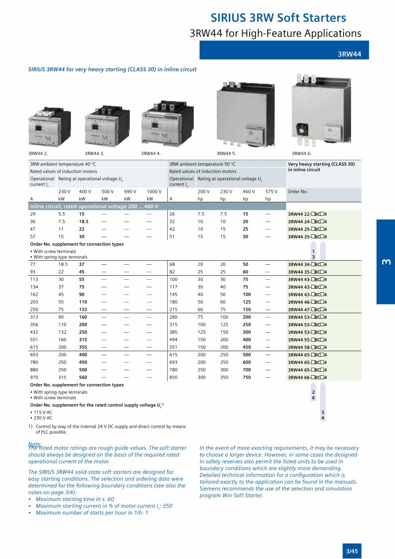
3RW44
The listed motor ratings are rough guide values. The soft starter should always be designed on the basis of the required rated operational current of the motor.
The SIRIUS 3RW44 solid-state soft starters are designed for easy starting conditions. The selection and ordering data were determined for the following boundary conditions (see also the notes on page 3/4):• Maximum starting time in s: 60• Maximum starting current in % of motor current Ie: 350• Maximum number of starts per hour in 1/h: 1
In the event of more exacting requirements, it may be necessary to choose a larger device. However, in some cases the designed-in safety reserves also permit the listed units to be used in boundary conditions which are slightly more demanding. Detailed technical information for a configuration which is tailored exactly to the application can be found in the manuals. Siemens recommends the use of the selection and simulation program Win-Soft Starter.
SIRIUS 3RW44 for very heavy starting (CLASS 30) in inline circuit
3RW442. 3RW443. 3RW444. 3RW445. 3RW446.
3RW ambient temperature 40 °C 3RWambienttemperature50°C Very heavy starting (CLASS 30) in inline circuitRated values of induction motors Rated values of induction motors
Operational current Ie
Rating at operational voltage Ue Operational current Ie
Rating at operational voltage Ue
230V 400V 500V 690V 1000V 200V 230V 460V 575V Order No.
A kW kW kW kW kW A hp hp hp hp
Inline circuit, rated operational voltage 200 ... 460 V29 5.5 15 — — — 26 7.5 7.5 15 — 3RW44 22- BC 4
36 7.5 18.5 — — — 32 10 10 20 — 3RW44 24- BC 4
47 11 22 — — — 42 10 15 25 — 3RW44 25- BC 4
57 15 30 — — — 51 15 15 30 — 3RW44 25- BC 4
Order No. supplement for connection types
•Withscrewterminals•Withspring-typeterminals
1 3
77 18.5 37 — — — 68 20 20 50 — 3RW44 34- BC 4
93 22 45 — — — 82 25 25 60 — 3RW44 35- BC 4
113 30 55 — — — 100 30 30 75 — 3RW44 43- BC 4
134 37 75 — — — 117 30 40 75 — 3RW44 43- BC 4
162 45 90 — — — 145 40 50 100 — 3RW44 43- BC 4
203 55 110 — — — 180 50 60 125 — 3RW44 46- BC 4
250 75 132 — — — 215 60 75 150 — 3RW44 47- BC 4
313 90 160 — — — 280 75 100 200 — 3RW44 53- BC 4
356 110 200 — — — 315 100 125 250 — 3RW44 53- BC 4
432 132 250 — — — 385 125 150 300 — 3RW44 53- BC 4
551 160 315 — — — 494 150 200 400 — 3RW44 55- BC 4
615 200 355 — — — 551 150 200 450 — 3RW44 58- BC 4
693 200 400 — — — 615 200 250 500 — 3RW44 65- BC 4
780 250 450 — — — 693 200 250 600 — 3RW44 65- BC 4
880 250 500 — — — 780 250 300 700 — 3RW44 65- BC 4
970 315 560 — — — 850 300 350 750 — 3RW44 66- BC 4
Order No. supplement for connection types
•Withspring-typeterminals•Withscrewterminals
2 6
Order No. supplement for the rated control supply voltage Us1)
•115VAC•230VAC
3 4
1) Controlbywayoftheinternal24VDCsupplyanddirectcontrolbymeans ofPLCpossible.
Note:
3RW44 for High-Feature Applications
SIRIUS 3RW Soft Starters
3/45
3

3RW44
3RW ambient temperature 40 °C 3RWambienttemperature50°C Very heavy starting (CLASS 30) in inline circuitRated values of induction motors Rated values of induction motors
Operational current Ie
Rating at operational voltage Ue Operational current Ie
Rating at operational voltage Ue
230V 400V 500V 690V 1000V 200V 230V 460V 575V Order No.
A kW kW kW kW kW A hp hp hp hp
Inline circuit, rated operational voltage 400 ... 600 V29 — 15 18.5 — — 26 — — 15 20 3RW44 22- BC 5
36 — 18.5 22 — — 32 — — 20 25 3RW44 24- BC 5
47 — 22 30 — — 42 — — 25 30 3RW44 25- BC 5
57 — 30 37 — — 51 — — 30 40 3RW44 25- BC 5
Order No. supplement for connection types
•Withscrewterminals•Withspring-typeterminals
1 3
77 — 37 45 — — 68 — — 50 50 3RW44 34- BC 5
93 — 45 55 — — 82 — — 60 75 3RW44 35- BC 5
113 — 55 75 — — 100 — — 75 75 3RW44 43- BC 5
134 — 75 90 — — 117 — — 75 100 3RW44 43- BC 5
162 — 90 110 — — 145 — — 100 125 3RW44 43- BC 5
203 — 110 132 — — 180 — — 125 150 3RW44 46- BC 5
250 — 132 160 — — 215 — — 150 200 3RW44 47- BC 5
313 — 160 200 — — 280 — — 200 250 3RW44 53- BC 5
356 — 200 250 — — 315 — — 250 300 3RW44 53- BC 5
432 — 250 315 — — 385 — — 300 400 3RW44 53- BC 5
551 — 315 355 — — 494 — — 400 500 3RW44 55- BC 5
615 — 355 400 — — 551 — — 450 600 3RW44 58- BC 5
693 — 400 500 — — 615 — — 500 700 3RW44 65- BC 5
780 — 450 560 — — 693 — — 600 750 3RW44 65- BC 5
880 — 500 630 — — 780 — — 700 850 3RW44 65- BC 5
— — — — — — 850 — — 750 900 3RW44 66- BC 5
Order No. supplement for connection types
•Withspring-typeterminals•Withscrewterminals
2 6
Order No. supplement for the rated control supply voltage Us1)
•115VAC•230VAC
3 4
1) Controlbywayoftheinternal24VDCsupplyanddirectcontrolbymeansofPLCpossible.
Note:
The listed motor ratings are rough guide values. The soft starter should always be designed on the basis of the required rated operational current of the motor.
The SIRIUS 3RW44 solid-state soft starters are designed for easy starting conditions. The selection and ordering data were determined for the following boundary conditions (see also the notes on page 3/4):• Maximum starting time in s: 60• Maximum starting current in % of motor current Ie: 350• Maximum number of starts per hour in 1/h: 1
In the event of more exacting requirements, it may be necessary to choose a larger device. However, in some cases the designed-in safety reserves also permit the listed units to be used in boundary conditions which are slightly more demanding. Detailed technical information for a configuration which is tailored exactly to the application can be found in the manuals. Siemens recommends the use of the selection and simulation program Win-Soft Starter.
3RW44 for High-Feature Applications
SIRIUS 3RW Soft Starters
3/46
3
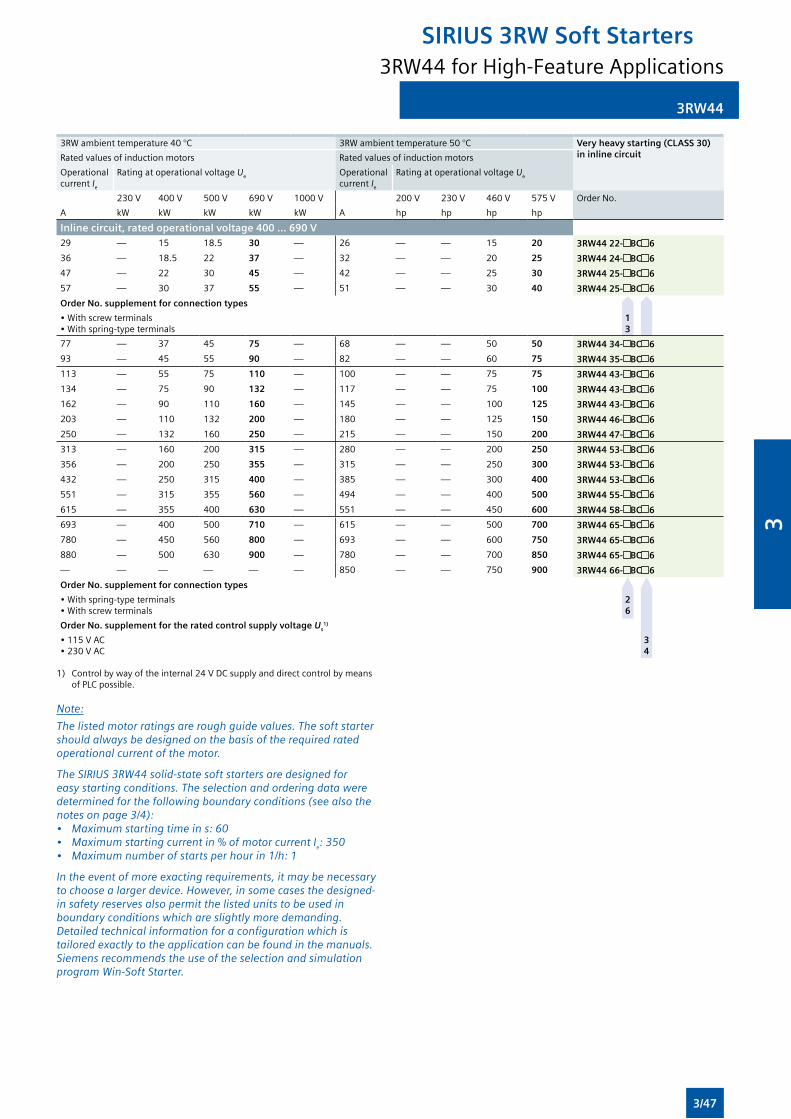
3RW44
3RW ambient temperature 40 °C 3RWambienttemperature50°C Very heavy starting (CLASS 30) in inline circuitRated values of induction motors Rated values of induction motors
Operational current Ie
Rating at operational voltage Ue Operational current Ie
Rating at operational voltage Ue
230V 400V 500V 690V 1000V 200V 230V 460V 575V Order No.
A kW kW kW kW kW A hp hp hp hp
Inline circuit, rated operational voltage 400 ... 690 V29 — 15 18.5 30 — 26 — — 15 20 3RW44 22- BC 6
36 — 18.5 22 37 — 32 — — 20 25 3RW44 24- BC 6
47 — 22 30 45 — 42 — — 25 30 3RW44 25- BC 6
57 — 30 37 55 — 51 — — 30 40 3RW44 25- BC 6
Order No. supplement for connection types
•Withscrewterminals•Withspring-typeterminals
1 3
77 — 37 45 75 — 68 — — 50 50 3RW44 34- BC 6
93 — 45 55 90 — 82 — — 60 75 3RW44 35- BC 6
113 — 55 75 110 — 100 — — 75 75 3RW44 43- BC 6
134 — 75 90 132 — 117 — — 75 100 3RW44 43- BC 6
162 — 90 110 160 — 145 — — 100 125 3RW44 43- BC 6
203 — 110 132 200 — 180 — — 125 150 3RW44 46- BC 6
250 — 132 160 250 — 215 — — 150 200 3RW44 47- BC 6
313 — 160 200 315 — 280 — — 200 250 3RW44 53- BC 6
356 — 200 250 355 — 315 — — 250 300 3RW44 53- BC 6
432 — 250 315 400 — 385 — — 300 400 3RW44 53- BC 6
551 — 315 355 560 — 494 — — 400 500 3RW44 55- BC 6
615 — 355 400 630 — 551 — — 450 600 3RW44 58- BC 6
693 — 400 500 710 — 615 — — 500 700 3RW44 65- BC 6
780 — 450 560 800 — 693 — — 600 750 3RW44 65- BC 6
880 — 500 630 900 — 780 — — 700 850 3RW44 65- BC 6
— — — — — — 850 — — 750 900 3RW44 66- BC 6
Order No. supplement for connection types
•Withspring-typeterminals•Withscrewterminals
2 6
Order No. supplement for the rated control supply voltage Us1)
•115VAC•230VAC
3 4
1) Controlbywayoftheinternal24VDCsupplyanddirectcontrolbymeansofPLCpossible.
Note:
The listed motor ratings are rough guide values. The soft starter should always be designed on the basis of the required rated operational current of the motor.
The SIRIUS 3RW44 solid-state soft starters are designed for easy starting conditions. The selection and ordering data were determined for the following boundary conditions (see also the notes on page 3/4):• Maximum starting time in s: 60• Maximum starting current in % of motor current Ie: 350• Maximum number of starts per hour in 1/h: 1
In the event of more exacting requirements, it may be necessary to choose a larger device. However, in some cases the designed-in safety reserves also permit the listed units to be used in boundary conditions which are slightly more demanding. Detailed technical information for a configuration which is tailored exactly to the application can be found in the manuals. Siemens recommends the use of the selection and simulation program Win-Soft Starter.
3RW44 for High-Feature Applications
SIRIUS 3RW Soft Starters
3/47
3
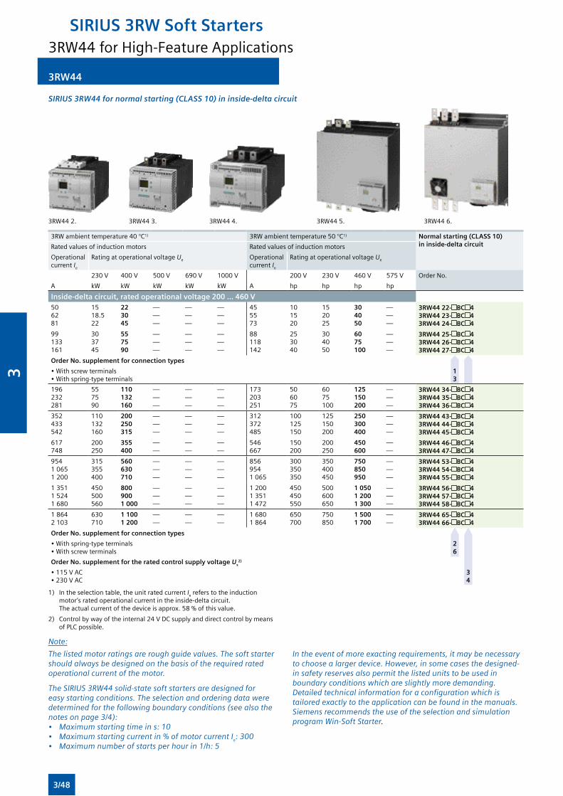
3RW44
SIRIUS 3RW44 for normal starting (CLASS 10) in inside-delta circuit
3RW442. 3RW443. 3RW444. 3RW445. 3RW446.
3RW ambient temperature 40 °C1) 3RWambienttemperature50°C1) Normal starting (CLASS 10) in inside-delta circuitRated values of induction motors Rated values of induction motors
Operational current Ie
Rating at operational voltage Ue Operational current Ie
Rating at operational voltage Ue
230V 400V 500V 690V 1000V 200V 230V 460V 575V Order No.
A kW kW kW kW kW A hp hp hp hp
Inside-delta circuit, rated operational voltage 200 ... 460 V506281
1518.522
223045
———
———
———
455573
101520
152025
304050
———
3RW44 22- BC 43RW44 23- BC 43RW44 24- BC 4
99133161
303745
557590
———
———
———
88118142
253040
304050
6075100
———
3RW44 25- BC 43RW44 26- BC 43RW44 27- BC 4
Order No. supplement for connection types
•Withscrewterminals•Withspring-typeterminals
1 3
196232281
557590
110132160
———
———
———
173203251
506075
6075100
125150200
———
3RW44 34- BC 43RW44 35- BC 43RW44 36- BC 4
352433542
110132160
200250315
———
———
———
312372485
100125150
125150200
250300400
———
3RW44 43- BC 43RW44 44- BC 43RW44 45- BC 4
617748
200250
355400
——
——
——
546667
150200
200250
450600
——
3RW44 46- BC 43RW44 47- BC 4
95410651 200
315355400
560630710
———
———
———
8569541065
300350350
350400450
750850950
———
3RW44 53- BC 43RW44 54- BC 43RW44 55- BC 4
135115241 680
450500560
8009001 000
———
———
———
1 20013511472
450450550
500600650
1 0501 2001 300
———
3RW44 56- BC 43RW44 57- BC 43RW44 58- BC 4
1 8642 103
630710
1 1001 200
——
——
——
1 6801 864
650700
750850
1 5001 700
——
3RW44 65- BC 43RW44 66- BC 4
Order No. supplement for connection types
•Withspring-typeterminals•Withscrewterminals
2 6
Order No. supplement for the rated control supply voltage Us2)
•115VAC•230VAC
3 4
1) Intheselectiontable,theunitratedcurrentIe refers to the induction motor’sratedoperationalcurrentintheinside-deltacircuit. Theactualcurrentofthedeviceisapprox.58%ofthisvalue.
2) Controlbywayoftheinternal24VDCsupplyanddirectcontrolbymeans ofPLCpossible.
Note:
The listed motor ratings are rough guide values. The soft starter should always be designed on the basis of the required rated operational current of the motor.
The SIRIUS 3RW44 solid-state soft starters are designed for easy starting conditions. The selection and ordering data were determined for the following boundary conditions (see also the notes on page 3/4):• Maximum starting time in s: 10• Maximum starting current in % of motor current Ie: 300• Maximum number of starts per hour in 1/h: 5
In the event of more exacting requirements, it may be necessary to choose a larger device. However, in some cases the designed-in safety reserves also permit the listed units to be used in boundary conditions which are slightly more demanding. Detailed technical information for a configuration which is tailored exactly to the application can be found in the manuals. Siemens recommends the use of the selection and simulation program Win-Soft Starter.
3RW44 for High-Feature Applications
SIRIUS 3RW Soft Starters
3/48
3
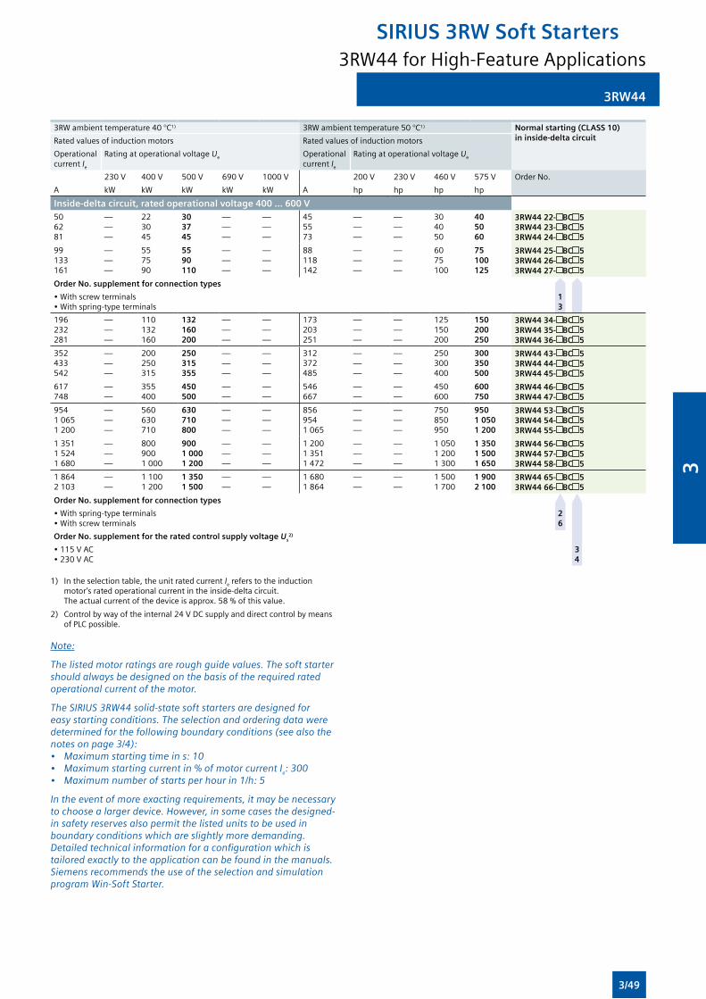
3RW44
3RW ambient temperature 40 °C1) 3RWambienttemperature50°C1) Normal starting (CLASS 10) in inside-delta circuitRated values of induction motors Rated values of induction motors
Operational current Ie
Rating at operational voltage Ue Operational current Ie
Rating at operational voltage Ue
230V 400V 500V 690V 1000V 200V 230V 460V 575V Order No.
A kW kW kW kW kW A hp hp hp hp
Inside-delta circuit, rated operational voltage 400 ... 600 V506281
———
223045
303745
———
———
455573
———
———
304050
405060
3RW44 22- BC 53RW44 23- BC 53RW44 24- BC 5
99133161
———
557590
5590110
———
———
88118142
———
———
6075100
75100125
3RW44 25- BC 53RW44 26- BC 53RW44 27- BC 5
Order No. supplement for connection types
•Withscrewterminals•Withspring-typeterminals
1 3
196232281
———
110132160
132160200
———
———
173203251
———
———
125150200
150200250
3RW44 34- BC 53RW44 35- BC 53RW44 36- BC 5
352433542
———
200250315
250315355
———
———
312372485
———
———
250300400
300350500
3RW44 43- BC 53RW44 44- BC 53RW44 45- BC 5
617748
——
355400
450500
——
——
546667
——
——
450600
600750
3RW44 46- BC 53RW44 47- BC 5
95410651 200
———
560630710
630710800
———
———
8569541065
———
———
750850950
9501 0501 200
3RW44 53- BC 53RW44 54- BC 53RW44 55- BC 5
135115241 680
———
8009001 000
9001 0001 200
———
———
1 20013511472
———
———
10501 2001 300
1 3501 5001 650
3RW44 56- BC 53RW44 57- BC 53RW44 58- BC 5
1 8642 103
——
1 1001 200
1 3501 500
——
——
1 6801 864
——
——
15001700
1 9002 100
3RW44 65- BC 53RW44 66- BC 5
Order No. supplement for connection types
•Withspring-typeterminals•Withscrewterminals
2 6
Order No. supplement for the rated control supply voltage Us2)
•115VAC•230VAC
3 4
1) Intheselectiontable,theunitratedcurrentIe refers to the induction motor’sratedoperationalcurrentintheinside-deltacircuit. Theactualcurrentofthedeviceisapprox.58%ofthisvalue.
2) Controlbywayoftheinternal24VDCsupplyanddirectcontrolbymeansofPLCpossible.
Note:
The listed motor ratings are rough guide values. The soft starter should always be designed on the basis of the required rated operational current of the motor.
The SIRIUS 3RW44 solid-state soft starters are designed for easy starting conditions. The selection and ordering data were determined for the following boundary conditions (see also the notes on page 3/4):• Maximum starting time in s: 10• Maximum starting current in % of motor current Ie: 300• Maximum number of starts per hour in 1/h: 5
In the event of more exacting requirements, it may be necessary to choose a larger device. However, in some cases the designed-in safety reserves also permit the listed units to be used in boundary conditions which are slightly more demanding. Detailed technical information for a configuration which is tailored exactly to the application can be found in the manuals. Siemens recommends the use of the selection and simulation program Win-Soft Starter.
3RW44 for High-Feature Applications
SIRIUS 3RW Soft Starters
3/49
3
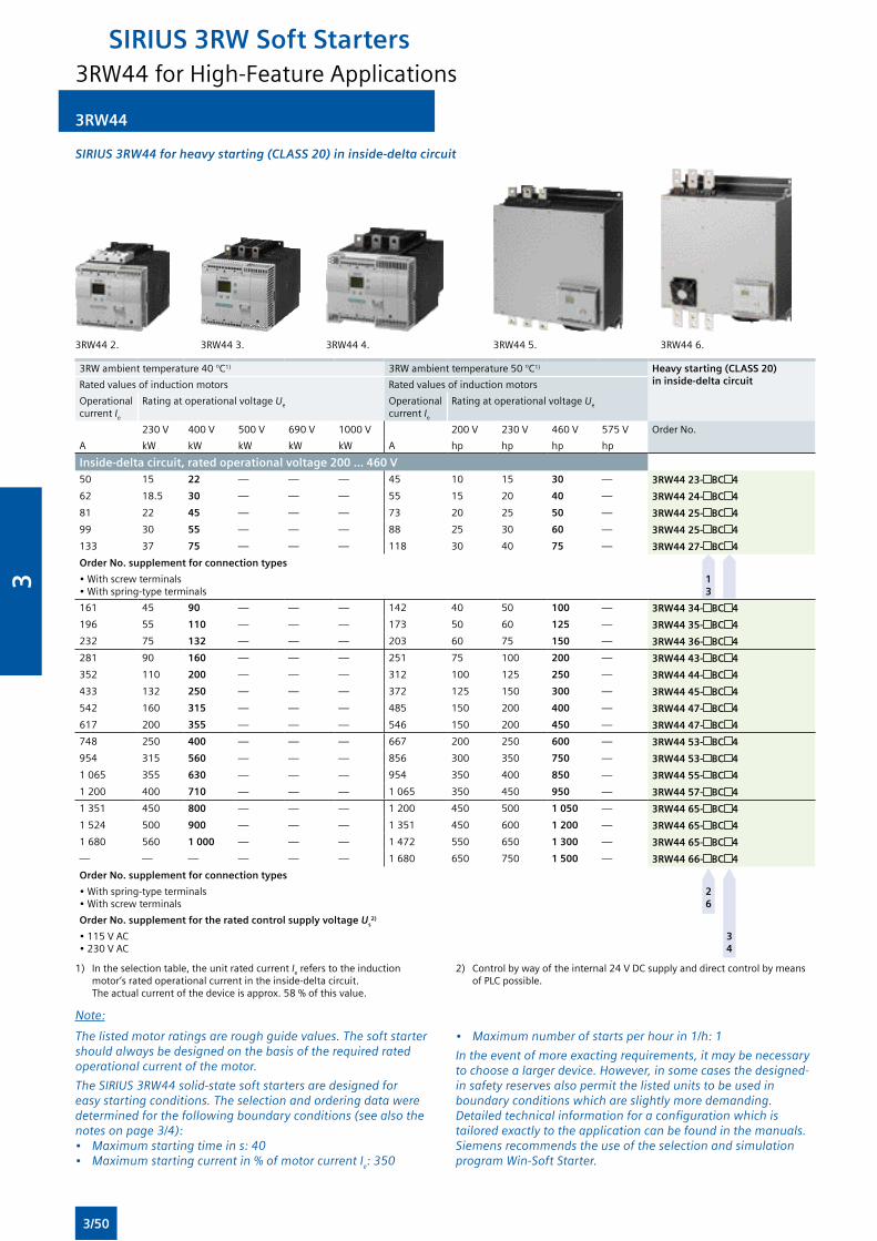
3RW44
SIRIUS 3RW44 for heavy starting (CLASS 20) in inside-delta circuit
3RW442. 3RW443. 3RW444. 3RW445. 3RW446.
3RW ambient temperature 40 °C1) 3RWambienttemperature50°C1) Heavy starting (CLASS 20) in inside-delta circuitRated values of induction motors Rated values of induction motors
Operational current Ie
Rating at operational voltage Ue Operational current Ie
Rating at operational voltage Ue
230V 400V 500V 690V 1000V 200V 230V 460V 575V Order No.
A kW kW kW kW kW A hp hp hp hp
Inside-delta circuit, rated operational voltage 200 ... 460 V50 15 22 — — — 45 10 15 30 — 3RW44 23- BC 4
62 18.5 30 — — — 55 15 20 40 — 3RW44 24- BC 4
81 22 45 — — — 73 20 25 50 — 3RW44 25- BC 4
99 30 55 — — — 88 25 30 60 — 3RW44 25- BC 4
133 37 75 — — — 118 30 40 75 — 3RW44 27- BC 4
Order No. supplement for connection types
•Withscrewterminals•Withspring-typeterminals
1 3
161 45 90 — — — 142 40 50 100 — 3RW44 34- BC 4
196 55 110 — — — 173 50 60 125 — 3RW44 35- BC 4
232 75 132 — — — 203 60 75 150 — 3RW44 36- BC 4
281 90 160 — — — 251 75 100 200 — 3RW44 43- BC 4
352 110 200 — — — 312 100 125 250 — 3RW44 44- BC 4
433 132 250 — — — 372 125 150 300 — 3RW44 45- BC 4
542 160 315 — — — 485 150 200 400 — 3RW44 47- BC 4
617 200 355 — — — 546 150 200 450 — 3RW44 47- BC 4
748 250 400 — — — 667 200 250 600 — 3RW44 53- BC 4
954 315 560 — — — 856 300 350 750 — 3RW44 53- BC 4
1065 355 630 — — — 954 350 400 850 — 3RW44 55- BC 4
1 200 400 710 — — — 1065 350 450 950 — 3RW44 57- BC 4
1351 450 800 — — — 1 200 450 500 1 050 — 3RW44 65- BC 4
1524 500 900 — — — 1351 450 600 1 200 — 3RW44 65- BC 4
1 680 560 1 000 — — — 1472 550 650 1 300 — 3RW44 65- BC 4
— — — — — — 1 680 650 750 1 500 — 3RW44 66- BC 4
Order No. supplement for connection types
•Withspring-typeterminals•Withscrewterminals
2 6
Order No. supplement for the rated control supply voltage Us2)
•115VAC•230VAC
3 4
1) Intheselectiontable,theunitratedcurrentIe refers to the induction motor’sratedoperationalcurrentintheinside-deltacircuit. Theactualcurrentofthedeviceisapprox.58%ofthisvalue.
2) Controlbywayoftheinternal24VDCsupplyanddirectcontrolbymeansofPLCpossible.
Note:
The listed motor ratings are rough guide values. The soft starter should always be designed on the basis of the required rated operational current of the motor.
The SIRIUS 3RW44 solid-state soft starters are designed for easy starting conditions. The selection and ordering data were determined for the following boundary conditions (see also the notes on page 3/4):• Maximum starting time in s: 40• Maximum starting current in % of motor current Ie: 350
• Maximum number of starts per hour in 1/h: 1
In the event of more exacting requirements, it may be necessary to choose a larger device. However, in some cases the designed-in safety reserves also permit the listed units to be used in boundary conditions which are slightly more demanding. Detailed technical information for a configuration which is tailored exactly to the application can be found in the manuals. Siemens recommends the use of the selection and simulation program Win-Soft Starter.
3RW44 for High-Feature Applications
SIRIUS 3RW Soft Starters
3/50
3
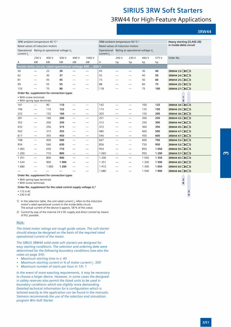
3RW44
3RW ambient temperature 40 °C1) 3RWambienttemperature50°C1) Heavy starting (CLASS 20) in inside-delta circuitRated values of induction motors Rated values of induction motors
Operational current Ie
Rating at operational voltage Ue Operational current Ie
Rating at operational voltage Ue
230V 400V 500V 690V 1000V 200V 230V 460V 575V Order No.
A kW kW kW kW kW A hp hp hp hp
Inside-delta circuit, rated operational voltage 400 ... 600 V50 — 22 30 — — 45 — — 30 40 3RW44 23- BC 5
62 — 30 37 — — 55 — — 40 50 3RW44 24- BC 5
81 — 45 45 — — 73 — — 50 60 3RW44 25- BC 5
99 — 55 55 — — 88 — — 60 75 3RW44 25- BC 5
133 — 75 90 — — 118 — — 75 100 3RW44 27- BC 5
Order No. supplement for connection types
•Withscrewterminals•Withspring-typeterminals
1 3
161 — 90 110 — — 142 — — 100 125 3RW44 34- BC 5
196 — 110 132 — — 173 — — 125 150 3RW44 35- BC 5
232 — 132 160 — — 203 — — 150 200 3RW44 36- BC 5
281 — 160 200 — — 251 — — 200 250 3RW44 43- BC 5
352 — 200 250 — — 312 — — 250 300 3RW44 44- BC 5
433 — 250 315 — — 372 — — 300 350 3RW44 45- BC 5
542 — 315 355 — — 485 — — 400 500 3RW44 47- BC 5
617 — 355 450 — — 546 — — 450 600 3RW44 47- BC 5
748 — 400 500 — — 667 — — 600 750 3RW44 53- BC 5
954 — 560 630 — — 856 — — 750 950 3RW44 53- BC 5
1065 — 630 710 — — 954 — — 850 1 050 3RW44 55- BC 5
1 200 — 710 800 — — 1065 — — 950 1 200 3RW44 57- BC 5
1351 — 800 900 — — 1 200 — — 1050 1 350 3RW44 65- BC 5
1524 — 900 1 000 — — 1351 — — 1 200 1 500 3RW44 65- BC 5
1 680 — 1 000 1 200 — — 1472 — — 1 300 1 650 3RW44 65- BC 5
— — — — — — 1 680 — — 1500 1 900 3RW44 66- BC 5
Order No. supplement for connection types
•Withspring-typeterminals•Withscrewterminals
2 6
Order No. supplement for the rated control supply voltage Us2)
•115VAC•230VAC
3 4
1) Intheselectiontable,theunitratedcurrentIe refers to the induction motor’sratedoperationalcurrentintheinside-deltacircuit. Theactualcurrentofthedeviceisapprox.58%ofthisvalue.
2) Controlbywayoftheinternal24VDCsupplyanddirectcontrolbymeansofPLCpossible.
Note:
The listed motor ratings are rough guide values. The soft starter should always be designed on the basis of the required rated operational current of the motor.
The SIRIUS 3RW44 solid-state soft starters are designed for easy starting conditions. The selection and ordering data were determined for the following boundary conditions (see also the notes on page 3/4):• Maximum starting time in s: 40• Maximum starting current in % of motor current Ie: 350• Maximum number of starts per hour in 1/h: 1
In the event of more exacting requirements, it may be necessary to choose a larger device. However, in some cases the designed-in safety reserves also permit the listed units to be used in boundary conditions which are slightly more demanding. Detailed technical information for a configuration which is tailored exactly to the application can be found in the manuals. Siemens recommends the use of the selection and simulation program Win-Soft Starter.
3RW44 for High-Feature Applications
SIRIUS 3RW Soft Starters
3/51
3

3RW44
SIRIUS 3RW44 for very heavy starting (CLASS 30) in inside-delta circuit
3RW442. 3RW443. 3RW444. 3RW445. 3RW446.
3RW ambient temperature 40 °C1) 3RWambienttemperature50°C1) Very heavy starting (CLASS 30) in inside-delta circuitRated values of induction motors Rated values of induction motors
Operational current Ie
Rating at operational voltage Ue Operational current Ie
Rating at operational voltage Ue
230V 400V 500V 690V 1000V 200V 230V 460V 575V Order No.
A kW kW kW kW kW A hp hp hp hp
Inside-delta circuit, rated operational voltage 200 ... 460 V50 15 22 — — — 45 10 15 30 — 3RW44 23- BC 4
62 18.5 30 — — — 55 15 20 40 — 3RW44 24- BC 4
81 22 45 — — — 73 20 25 50 — 3RW44 25- BC 4
99 30 55 — — — 88 25 30 60 — 3RW44 25- BC 4
133 37 75 — — — 118 30 40 75 — 3RW44 27- BC 4
Order No. supplement for connection types
•Withscrewterminals•Withspring-typeterminals
1 3
161 45 90 — — — 142 40 50 100 — 3RW44 35- BC 4
196 55 110 — — — 173 50 60 125 — 3RW44 36- BC 4
232 75 132 — — — 203 60 75 150 — 3RW44 43- BC 4
281 90 160 — — — 251 75 100 200 — 3RW44 43- BC 4
352 110 200 — — — 312 100 125 250 — 3RW44 45- BC 4
433 132 250 — — — 372 125 150 300 — 3RW44 47- BC 4
542 160 315 — — — 485 150 200 400 — 3RW44 53- BC 4
617 200 355 — — — 546 150 200 450 — 3RW44 53- BC 4
748 250 400 — — — 667 200 250 600 — 3RW44 53- BC 4
954 315 560 — — — 856 300 350 750 — 3RW44 55- BC 4
1065 355 630 — — — 954 350 400 850 — 3RW44 58- BC 4
1 200 400 710 — — — 1065 350 450 950 — 3RW44 65- BC 4
1351 450 800 — — — 1 200 450 500 1 050 — 3RW44 65- BC 4
1524 500 900 — — — 1351 450 600 1 200 — 3RW44 65- BC 4
— — — — — — 1472 550 650 1 300 — 3RW44 66- BC 4
Order No. supplement for connection types
•Withspring-typeterminals•Withscrewterminals
2 6
Order No. supplement for the rated control supply voltage Us2)
•115VAC•230VAC
3 4
1) Intheselectiontable,theunitratedcurrentIe refers to the induction motor’sratedoperationalcurrentintheinside-deltacircuit. Theactualcurrentofthedeviceisapprox.58%ofthisvalue.
2) Controlbywayoftheinternal24VDCsupplyanddirectcontrolbymeansofPLCpossible.
Note:
The listed motor ratings are rough guide values. The soft starter should always be designed on the basis of the required rated operational current of the motor.
The SIRIUS 3RW44 solid-state soft starters are designed for easy starting conditions. The selection and ordering data were determined for the following boundary conditions (see also the notes on page 3/4):• Maximum starting time in s: 60• Maximum starting current in % of motor current Ie: 350
• Maximum number of starts per hour in 1/h: 1
In the event of more exacting requirements, it may be necessary to choose a larger device. However, in some cases the designed-in safety reserves also permit the listed units to be used in boundary conditions which are slightly more demanding. Detailed technical information for a configuration which is tailored exactly to the application can be found in the manuals. Siemens recommends the use of the selection and simulation program Win-Soft Starter.
3RW44 for High-Feature Applications
SIRIUS 3RW Soft Starters
3/52
3
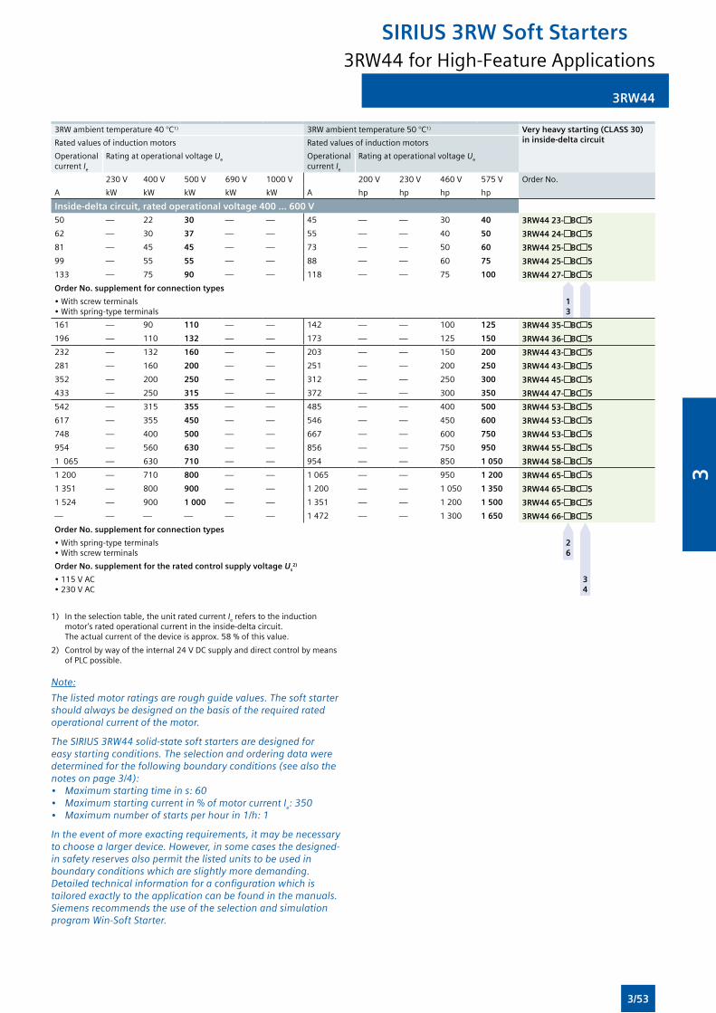
3RW44
3RW ambient temperature 40 °C1) 3RWambienttemperature50°C1) Very heavy starting (CLASS 30) in inside-delta circuitRated values of induction motors Rated values of induction motors
Operational current Ie
Rating at operational voltage Ue Operational current Ie
Rating at operational voltage Ue
230V 400V 500V 690V 1000V 200V 230V 460V 575V Order No.
A kW kW kW kW kW A hp hp hp hp
Inside-delta circuit, rated operational voltage 400 ... 600 V50 — 22 30 — — 45 — — 30 40 3RW44 23- BC 5
62 — 30 37 — — 55 — — 40 50 3RW44 24- BC 5
81 — 45 45 — — 73 — — 50 60 3RW44 25- BC 5
99 — 55 55 — — 88 — — 60 75 3RW44 25- BC 5
133 — 75 90 — — 118 — — 75 100 3RW44 27- BC 5
Order No. supplement for connection types
•Withscrewterminals•Withspring-typeterminals
1 3
161 — 90 110 — — 142 — — 100 125 3RW44 35- BC 5
196 — 110 132 — — 173 — — 125 150 3RW44 36- BC 5
232 — 132 160 — — 203 — — 150 200 3RW44 43- BC 5
281 — 160 200 — — 251 — — 200 250 3RW44 43- BC 5
352 — 200 250 — — 312 — — 250 300 3RW44 45- BC 5
433 — 250 315 — — 372 — — 300 350 3RW44 47- BC 5
542 — 315 355 — — 485 — — 400 500 3RW44 53- BC 5
617 — 355 450 — — 546 — — 450 600 3RW44 53- BC 5
748 — 400 500 — — 667 — — 600 750 3RW44 53- BC 5
954 — 560 630 — — 856 — — 750 950 3RW44 55- BC 5
1065 — 630 710 — — 954 — — 850 1 050 3RW44 58- BC 5
1 200 — 710 800 — — 1065 — — 950 1 200 3RW44 65- BC 5
1351 — 800 900 — — 1 200 — — 1050 1 350 3RW44 65- BC 5
1524 — 900 1 000 — — 1351 — — 1 200 1 500 3RW44 65- BC 5
— — — — — — 1472 — — 1 300 1 650 3RW44 66- BC 5
Order No. supplement for connection types
•Withspring-typeterminals•Withscrewterminals
2 6
Order No. supplement for the rated control supply voltage Us2)
•115VAC•230VAC
3 4
1) Intheselectiontable,theunitratedcurrentIe refers to the induction motor’sratedoperationalcurrentintheinside-deltacircuit. Theactualcurrentofthedeviceisapprox.58%ofthisvalue.
2) Controlbywayoftheinternal24VDCsupplyanddirectcontrolbymeansofPLCpossible.
Note:
The listed motor ratings are rough guide values. The soft starter should always be designed on the basis of the required rated operational current of the motor.
The SIRIUS 3RW44 solid-state soft starters are designed for easy starting conditions. The selection and ordering data were determined for the following boundary conditions (see also the notes on page 3/4):• Maximum starting time in s: 60• Maximum starting current in % of motor current Ie: 350• Maximum number of starts per hour in 1/h: 1
In the event of more exacting requirements, it may be necessary to choose a larger device. However, in some cases the designed-in safety reserves also permit the listed units to be used in boundary conditions which are slightly more demanding. Detailed technical information for a configuration which is tailored exactly to the application can be found in the manuals. Siemens recommends the use of the selection and simulation program Win-Soft Starter.
3RW44 for High-Feature Applications
SIRIUS 3RW Soft Starters
3/53
3
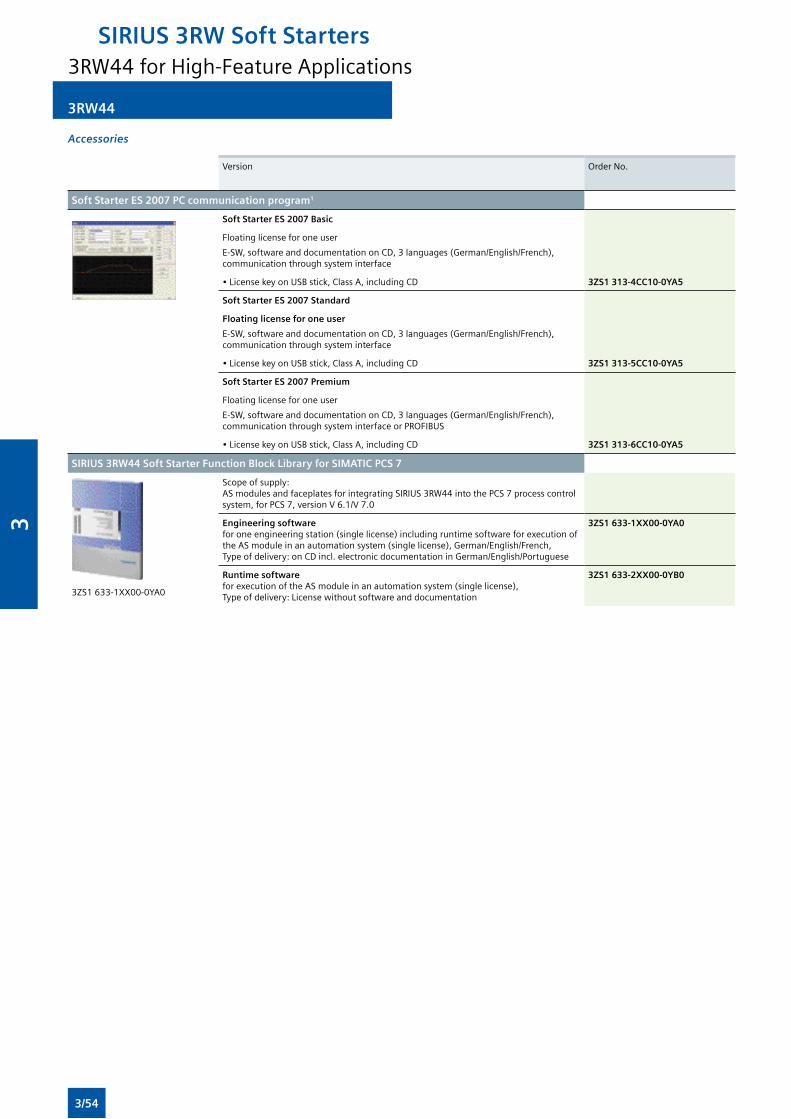
3RW44
Accessories
Version Order No.
Soft Starter ES 2007 PC communication program1
Soft Starter ES 2007 Basic
Floating license for one user
E-SW,softwareanddocumentationonCD,3languages(German/English/French),communicationthroughsysteminterface
•LicensekeyonUSBstick,ClassA,includingCD 3ZS1 313-4CC10-0YA5
Soft Starter ES 2007 Standard
Floating license for one user
E-SW,softwareanddocumentationonCD,3languages(German/English/French),communicationthroughsysteminterface
•LicensekeyonUSBstick,ClassA,includingCD 3ZS1 313-5CC10-0YA5
Soft Starter ES 2007 Premium
Floating license for one user
E-SW,softwareanddocumentationonCD,3languages(German/English/French),communicationthroughsysteminterfaceorPROFIBUS
•LicensekeyonUSBstick,ClassA,includingCD 3ZS1 313-6CC10-0YA5
SIRIUS 3RW44 Soft Starter Function Block Library for SIMATIC PCS 7
3ZS1633-1XX00-0YA0
Scopeofsupply: ASmodulesandfaceplatesforintegratingSIRIUS3RW44intothePCS7processcontrolsystem,forPCS7,versionV6.1/V7.0
Engineering software foroneengineeringstation(singlelicense)includingruntimesoftwareforexecutionoftheASmoduleinanautomationsystem(singlelicense),German/English/French, Typeofdelivery:onCDincl.electronicdocumentationinGerman/English/Portuguese
3ZS1 633-1XX00-0YA0
Runtime software forexecutionoftheASmoduleinanautomationsystem(singlelicense), Typeofdelivery:Licensewithoutsoftwareanddocumentation
3ZS1 633-2XX00-0YB0
3RW44 for High-Feature Applications
SIRIUS 3RW Soft Starters
3/54
3
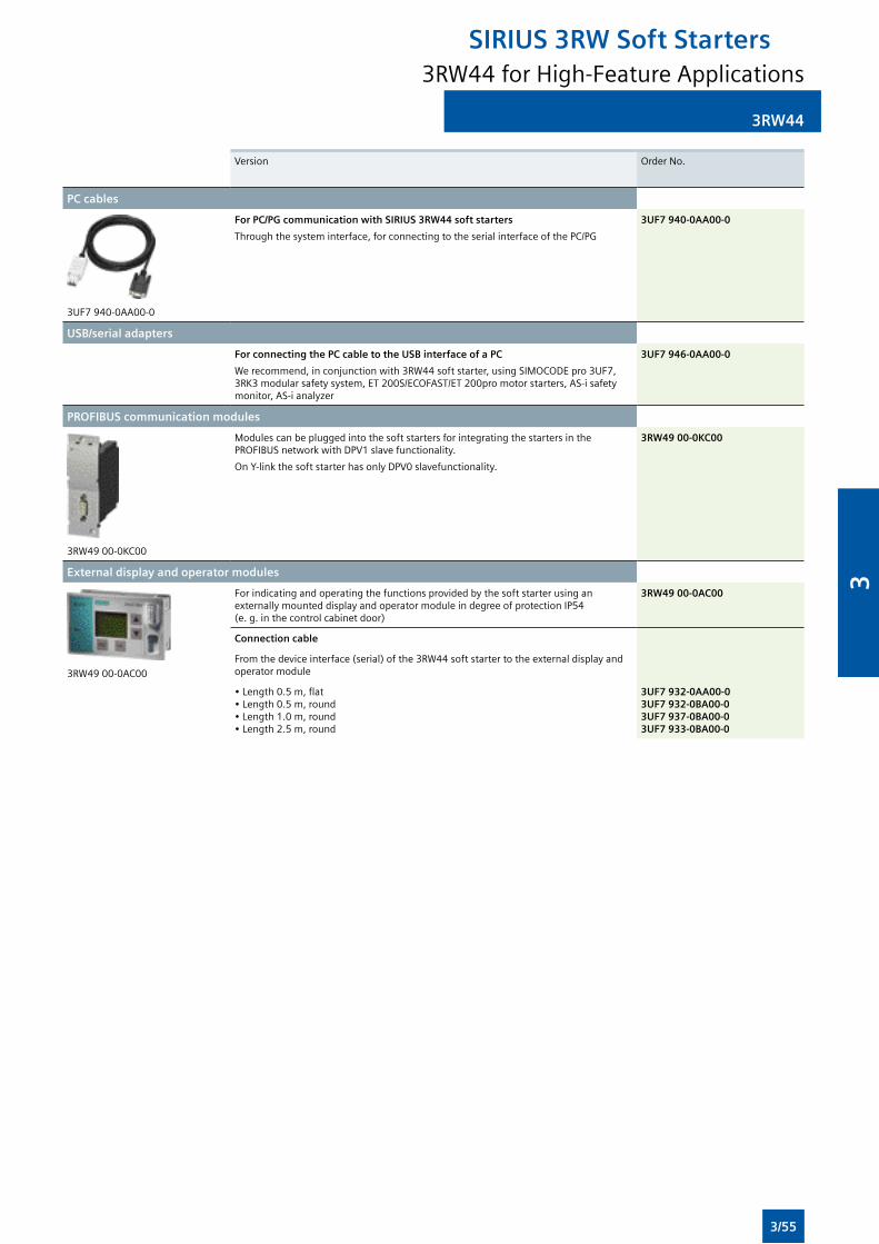
3RW44
Version Order No.
PC cables
3UF7940-0AA00-0
For PC/PG communication with SIRIUS 3RW44 soft starters
Throughthesysteminterface,forconnectingtotheserialinterfaceofthePC/PG
3UF7 940-0AA00-0
USB/serial adapters
For connecting the PC cable to the USB interface of a PC
Werecommend,inconjunctionwith3RW44softstarter,usingSIMOCODEpro3UF7,3RK3modularsafetysystem,ET200S/ECOFAST/ET200promotorstarters,AS-isafetymonitor,AS-ianalyzer
3UF7 946-0AA00-0
PROFIBUS communication modules
3RW4900-0KC00
ModulescanbepluggedintothesoftstartersforintegratingthestartersinthePROFIBUSnetworkwithDPV1slavefunctionality.
OnY-linkthesoftstarterhasonlyDPV0slavefunctionality.
3RW49 00-0KC00
External display and operator modules
3RW49 00-0AC00
ForindicatingandoperatingthefunctionsprovidedbythesoftstarterusinganexternallymounteddisplayandoperatormoduleindegreeofprotectionIP54 (e.g.inthecontrolcabinetdoor)
3RW49 00-0AC00
Connection cable
Fromthedeviceinterface(serial)ofthe3RW44softstartertotheexternaldisplayandoperator module
•Length0.5m,flat•Length0.5m,round•Length1.0m,round•Length2.5m,round
3UF7 932-0AA00-03UF7 932-0BA00-03UF7 937-0BA00-03UF7 933-0BA00-0
3RW44 for High-Feature Applications
SIRIUS 3RW Soft Starters
3/55
3
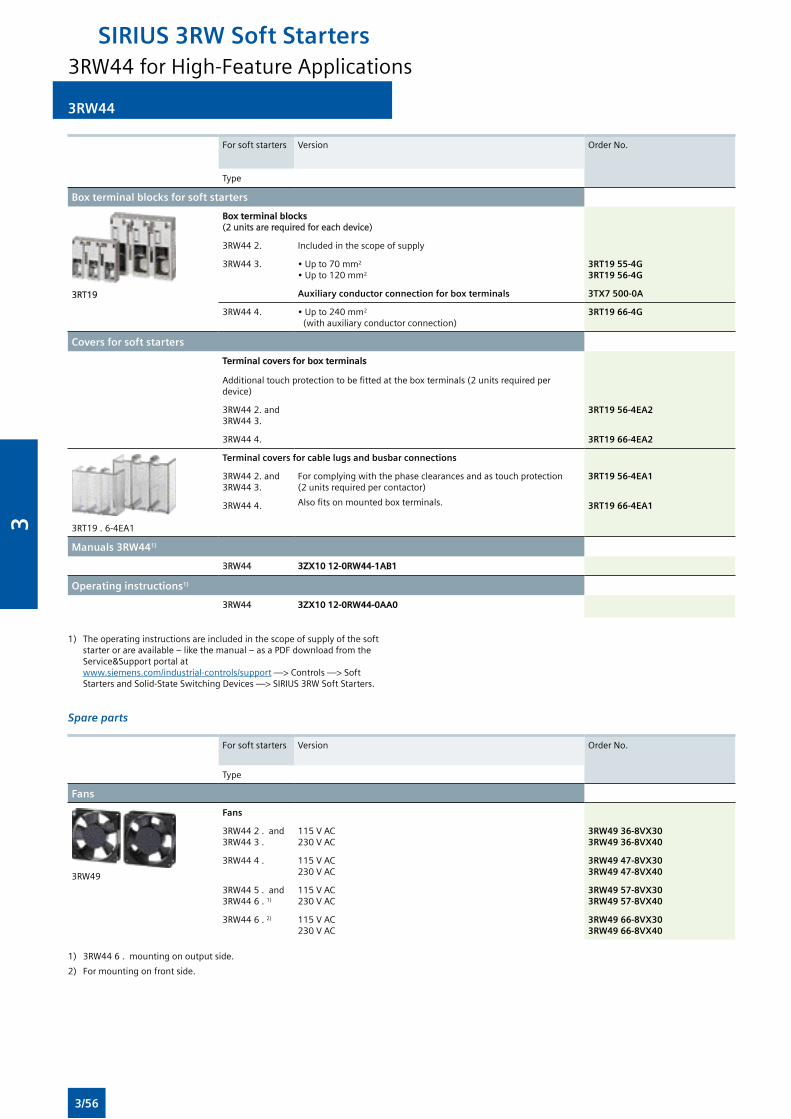
3RW44
For soft starters Version Order No.
Type
Box terminal blocks for soft starters
3RT19
Box terminal blocks (2unitsarerequiredforeachdevice)
3RW44 2. Includedinthescopeofsupply
3RW44 3. •Upto70mm2
•Upto120mm2
3RT19 55-4G3RT19 56-4G
Auxiliary conductor connection for box terminals 3TX7 500-0A
3RW44 4. •Upto240mm2
(withauxiliaryconductorconnection)3RT19 66-4G
Covers for soft starters
Terminal covers for box terminals
Additionaltouchprotectiontobefittedattheboxterminals(2unitsrequiredperdevice)
3RW44 2. and 3RW44 3.
3RT19 56-4EA2
3RW44 4. 3RT19 66-4EA2
3RT19.6-4EA1
Terminal covers for cable lugs and busbar connections
3RW44 2. and 3RW44 3.
Forcomplyingwiththephaseclearancesandastouchprotection (2unitsrequiredpercontactor)
Alsofitsonmountedboxterminals.
3RT19 56-4EA1
3RW44 4. 3RT19 66-4EA1
Manuals 3RW441)
3RW44 3ZX10 12-0RW44-1AB1
Operating instructions1)
3RW44 3ZX10 12-0RW44-0AA0
1) Theoperatinginstructionsareincludedinthescopeofsupplyofthesoft starterorareavailable–likethemanual–asaPDFdownloadfromthe Service&Support portal at www.siemens.com/industrial-controls/support —> Controls —> Soft StartersandSolid-StateSwitchingDevices—>SIRIUS3RWSoftStarters.
Spare parts
For soft starters Version Order No.
Type
Fans
3RW49
Fans
3RW44 2 . and 3RW44 3 .
115VAC230VAC
3RW49 36-8VX303RW49 36-8VX40
3RW44 4 . 115VAC230VAC
3RW49 47-8VX303RW49 47-8VX40
3RW445.and3RW44 6 . 1)
115VAC230VAC
3RW49 57-8VX303RW49 57-8VX40
3RW44 6 . 2) 115VAC230VAC
3RW49 66-8VX303RW49 66-8VX40
1) 3RW446.mountingonoutputside.
2) Formountingonfrontside.
3RW44 for High-Feature Applications
SIRIUS 3RW Soft Starters
3/56
3
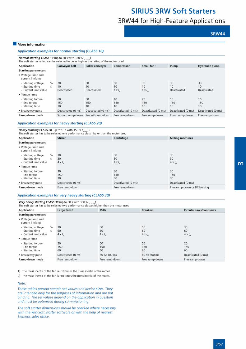
3RW44
More information
Application examples for normal starting (CLASS 10)
Normal starting CLASS 10 (upto20swith350% In motor) Thesoftstarterratingcanbeselectedtobeashighastheratingofthemotorused
Application Conveyor belt Roller conveyor Compressor Small fan1) Pump Hydraulic pump
Starting parameters
•Voltagerampandcurrent limiting
- Starting voltage - Starting time - Current limit value
%s
7010Deactivated
6010Deactivated
50104x IM
30104x IM
3010Deactivated
3010Deactivated
•Torqueramp
- Starting torque - Endtorque - Starting time
6015010
5015010
4015010
2015010
1015010
1015010
•Breakawaypulse Deactivated(0ms) Deactivated(0ms) Deactivated(0ms) Deactivated(0ms) Deactivated(0ms) Deactivated(0ms)
Ramp-down mode Smoothramp-down Smoothramp-down Freeramp-down Freeramp-down Pumpramp-down Freeramp-down
Application examples for heavy starting (CLASS 20)
Heavy starting CLASS 20 (upto40swith350% In motor) Thesoftstarterhastobeselectedoneperformanceclasshigherthanthemotorused
Application Stirrer Centrifuge Milling machines
Starting parameters
•Voltagerampandcurrent limiting
- Starting voltage - Starting time - Current limit value
%s
30304x IM
30304x IM
30304x IM
•Torqueramp
- Starting torque - Endtorque - Starting time
3015030
3015030
3015030
•Breakawaypulse Deactivated(0ms) Deactivated(0ms) Deactivated(0ms)
Ramp-down mode Freeramp-down Freeramp-down Freeramp-downorDCbraking
Application examples for very heavy starting (CLASS 30)
Very heavy starting CLASS 30 (upto60swith350% In motor) Thesoftstarterhastobeselectedtwoperformanceclasseshigherthanthemotorused
Application Large fans2) Mills Breakers Circular saws/bandsaws
Starting parameters
•Voltagerampandcurrent limiting
- Starting voltage - Starting time - Current limit value
%s
30604x IM
50604x IM
50604x IM
30604x IM
•Torqueramp
- Starting torque - Endtorque - Starting time
2015060
5015060
5015060
2015060
•Breakawaypulse Deactivated(0ms) 80%;300ms 80%;300ms Deactivated(0ms)
Ramp-down mode Freeramp-down Freeramp-down Freeramp-down Freeramp-down
1) Themassinertiaofthefanis<10timesthemassinertiaofthemotor.
2) Themassinertiaofthefanis³10timesthemassinertiaofthemotor.
Note:
These tables present sample set values and device sizes. They are intended only for the purposes of information and are not binding. The set values depend on the application in question and must be optimized during commissioning.
The soft starter dimensions should be checked where necessary with the Win-Soft Starter software or with the help of nearest Siemens sales office.
3RW44 for High-Feature Applications
SIRIUS 3RW Soft Starters
3/57
3
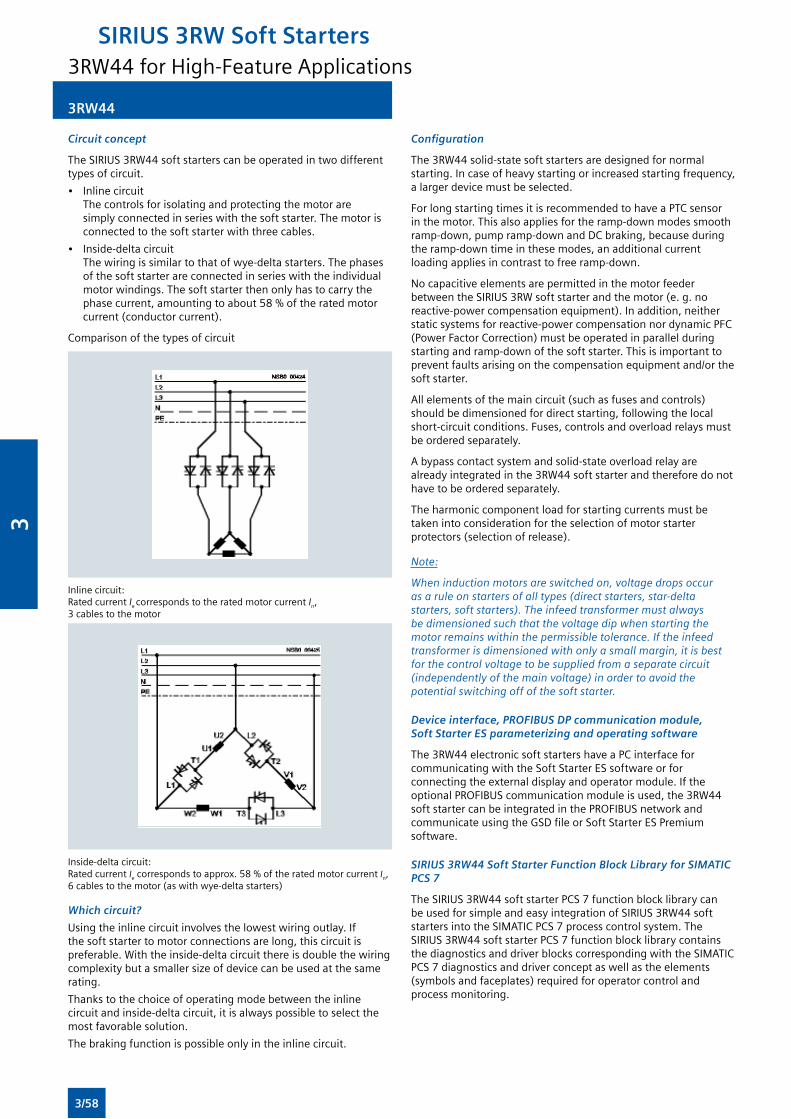
Circuit concept
TheSIRIUS3RW44softstarterscanbeoperatedintwodifferenttypesofcircuit.
• Inlinecircuit Thecontrolsforisolatingandprotectingthemotoraresimplyconnectedinserieswiththesoftstarter.Themotorisconnectedtothesoftstarterwiththreecables.
• Inside-deltacircuit Thewiringissimilartothatofwye-deltastarters.Thephasesofthesoftstarterareconnectedinserieswiththeindividualmotorwindings.Thesoftstarterthenonlyhastocarrythephasecurrent,amountingtoabout58%oftheratedmotorcurrent(conductorcurrent).
Comparisonofthetypesofcircuit
Inlinecircuit: Rated current Ie corresponds to the rated motor current In, 3 cables to the motor
Inside-deltacircuit: Rated current Iecorrespondstoapprox.58%oftheratedmotorcurrent In, 6cablestothemotor(aswithwye-deltastarters)
Which circuit?
Usingtheinlinecircuitinvolvesthelowestwiringoutlay.Ifthe soft starter to motor connections are long, this circuit is preferable.Withtheinside-deltacircuitthereisdoublethewiringcomplexitybutasmallersizeofdevicecanbeusedatthesamerating.
Thankstothechoiceofoperatingmodebetweentheinlinecircuitandinside-deltacircuit,itisalwayspossibletoselectthemost favorable solution.
Thebrakingfunctionispossibleonlyintheinlinecircuit.
3RW44
Configuration
The3RW44solid-statesoftstartersaredesignedfornormalstarting.Incaseofheavystartingorincreasedstartingfrequency,a larger device must be selected.
ForlongstartingtimesitisrecommendedtohaveaPTCsensorinthemotor.Thisalsoappliesfortheramp-downmodessmoothramp-down,pumpramp-downandDCbraking,becauseduringtheramp-downtimeinthesemodes,anadditionalcurrentloadingappliesincontrasttofreeramp-down.
No capacitive elements are permitted in the motor feeder betweentheSIRIUS3RWsoftstarterandthemotor(e.g.noreactive-powercompensationequipment).Inaddition,neitherstaticsystemsforreactive-powercompensationnordynamicPFC(PowerFactorCorrection)mustbeoperatedinparallelduringstartingandramp-downofthesoftstarter.Thisisimportanttoprevent faults arising on the compensation equipment and/or the soft starter.
Allelementsofthemaincircuit(suchasfusesandcontrols)shouldbedimensionedfordirectstarting,followingthelocalshort-circuitconditions.Fuses,controlsandoverloadrelaysmustbeorderedseparately.
Abypasscontactsystemandsolid-stateoverloadrelayarealreadyintegratedinthe3RW44softstarterandthereforedonothavetobeorderedseparately.
Theharmoniccomponentloadforstartingcurrentsmustbetakenintoconsiderationfortheselectionofmotorstarterprotectors(selectionofrelease).
Note:
When induction motors are switched on, voltage drops occur as a rule on starters of all types (direct starters, star-delta starters, soft starters). The infeed transformer must always be dimensioned such that the voltage dip when starting the motor remains within the permissible tolerance. If the infeed transformer is dimensioned with only a small margin, it is best for the control voltage to be supplied from a separate circuit (independently of the main voltage) in order to avoid the potential switching off of the soft starter.
Device interface, PROFIBUS DP communication module, Soft Starter ES parameterizing and operating software
The3RW44electronicsoftstartershaveaPCinterfaceforcommunicatingwiththeSoftStarterESsoftwareorforconnectingtheexternaldisplayandoperatormodule.IftheoptionalPROFIBUScommunicationmoduleisused,the3RW44softstartercanbeintegratedinthePROFIBUSnetworkandcommunicateusingtheGSDfileorSoftStarterESPremiumsoftware.
SIRIUS 3RW44 Soft Starter Function Block Library for SIMATIC PCS 7
TheSIRIUS3RW44softstarterPCS7functionblocklibrarycanbeusedforsimpleandeasyintegrationofSIRIUS3RW44softstartersintotheSIMATICPCS7processcontrolsystem.TheSIRIUS3RW44softstarterPCS7functionblocklibrarycontainsthediagnosticsanddriverblockscorrespondingwiththeSIMATICPCS7diagnosticsanddriverconceptaswellastheelements(symbolsandfaceplates)requiredforoperatorcontrolandprocess monitoring.
3RW44 for High-Feature Applications
SIRIUS 3RW Soft Starters
3/58
3
3RW44
Manual for SIRIUS 3RW44
Besidescontainingallimportantinformationonconfiguring,commissioningandservicing,themanualalsocontainsexamplecircuitsandthetechnicalspecificationsforalldevices.
Win-Soft Starter selection and simulation program
Withthissoftware,youcansimulateandselectallSiemenssoftstarters,takingintoaccountvariousparameterssuchasmains properties, motor and load data, and special application requirements.
Thesoftwareisavaluabletool,whichmakescomplicated,lengthymanualcalculationsfordeterminingtherequiredsoftstarterssuperfluous.
TheWin-SoftStarterselectionandsimulationprogramcanbedownloadedfrom: www.siemens.com/softstarter—>Software
YoucanfindmoreinformationaboutsoftstartersontheInternetlikewiseat: www.siemens.com/softstarter
3RW44 for High-Feature Applications
SIRIUS 3RW Soft Starters
3/59
3

Notes
SIRIUS 3RW Soft Starters
3/60
3
Protection Equipment
Accessories
4/46 Mountable accessories
4/49 Busbar accessories
4/51 Rotary operating mechanisms
4/53 Mounting accessories
4/54 Enclosures and front plates
Overload Relays
4/56 General Data
SIRIUS 3RU2Thermal Overload Relays new
4/63 3RU2 up to 40 A for Standard applications
4/70 Accessories
SIRIUS 3RU1Thermal Overload Relays
4/72 3RU11 up to 100 A for Standard applications
4/79 Accessories
SIRIUS 3RB3Solid-State Overload Relays new
4/81 3RB30, 3RB31 up to 40 A for Standard applications
4/89 Accessories
SIRIUS 3RB2Solid-State Overload Relays
4/90 3RB20, 3RB21 up to 630 A for Standard applications
4/99 Accessories for 3RB20, 3RB21
4/100 3RB22, 3RB23, 3RB24 new up to 630 A High-Feature applications
4/110 Accessories for 3RB22, 3RB23, 3RB24 new
4/2 Introduction
Motor Protection Circuit Breakers
SIRIUS 3RV2 Motor Protection Circuit Breakers up to 40 A
4/6 General data
4/11 For motor protection
4/12 For motor protection with overload relay function
4/13 For starter combinations
4/14 For transformer protection
4/15 For system protection according to UL 489/CSA C22.2 No. 5-02
4/16 For transformer protection according to UL 489/CSA C22.2 No.5-02
Accessories
4/17 Mountable accessories
4/20 Busbar accessories
4/23 3RV29 infeed system
4/27 Rotary operating mechanisms
4/28 Mounting accessories
4/31 Enclosures and front plates
SIRIUS 3RV1 Motor Protection Circuit Breakers up to 100 A
4/34 General data
4/40 For motor protection
4/41 For motor protection with overload relay function
4/42 For starter combinations
4/43 For transformer protection
4/44 For fuse monitoring
4/45 For system protection according to UL 489/CSA C22.2 No. 5-02
4
4
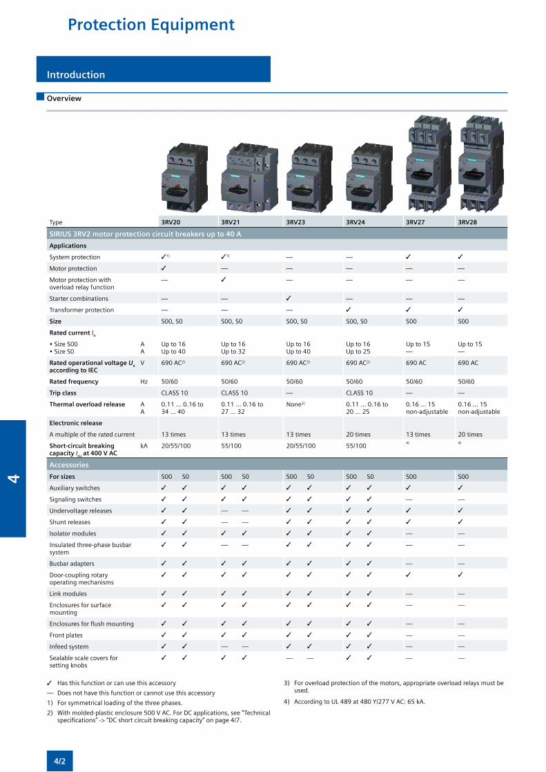
Protection Equipment
Introduction
Overview
Type 3RV20 3RV21 3RV23 3RV24 3RV27 3RV28
SIRIUS 3RV2 motor protection circuit breakers up to 40 A
Applications
System protection 31) 31) — — 3 3
Motor protection 3 — — — — —
Motor protection with overload relay function
— 3 — — — —
Starter combinations — — 3 — — —
Transformer protection — — — 3 3 3
Size S00, S0 S00, S0 S00, S0 S00, S0 S00 S00
Rated current In
• Size S00• Size S0
AA
Up to 16Up to 40
Up to 16Up to 32
Up to 16Up to 40
Up to 16Up to 25
Up to 15—
Up to 15—
Rated operational voltage Ue according to IEC
V 690 AC2) 690 AC2) 690 AC2) 690 AC2) 690 AC 690 AC
Rated frequency Hz 50/60 50/60 50/60 50/60 50/60 50/60
Trip class CLASS 10 CLASS 10 — CLASS 10 — —
Thermal overload release AA
0.11 ... 0.16 to34 ... 40
0.11 ... 0.16 to27 ... 32
None3) 0.11 ... 0.16 to20 ... 25
0.16 ... 15non-adjustable
0.16 ... 15non-adjustable
Electronic release
A multiple of the rated current 13 times 13 times 13 times 20 times 13 times 20 times
Short-circuit breaking capacity Icu at 400 V AC
kA 20/55/100 55/100 20/55/100 55/1004) 4)
Accessories
For sizes S00 S0 S00 S0 S00 S0 S00 S0 S00 S00
Auxiliary switches 3 3 3 3 3 3 3 3 3 3
Signaling switches 3 3 3 3 3 3 3 3 — —
Undervoltage releases 3 3 — — 3 3 3 3 3 3
Shunt releases 3 3 — — 3 3 3 3 3 3
Isolator modules 3 3 3 3 3 3 3 3 — —
Insulated three-phase busbar system
3 3 — — 3 3 3 3 — —
Busbar adapters 3 3 3 3 3 3 3 3 — —
Door-coupling rotary operating mechanisms
3 3 3 3 3 3 3 3 3 3
Link modules 3 3 3 3 3 3 3 3 — —
Enclosures for surface mounting
3 3 3 3 3 3 3 3 — —
Enclosures for flush mounting 3 3 3 3 3 3 3 3 — —
Front plates 3 3 3 3 3 3 3 3 — —
Infeed system 3 3 — — 3 3 3 3 — —
Sealable scale covers for setting knobs
3 3 3 3 — — 3 3 — —
3 Has this function or can use this accessory
— Does not have this function or cannot use this accessory
1) For symmetrical loading of the three phases.
2) With molded-plastic enclosure 500 V AC. For DC applications, see “Technical specifications” -> “DC short circuit breaking capacity” on page 4/7.
3) For overload protection of the motors, appropriate overload relays must be used.
4) According to UL 489 at 480 Y/277 V AC: 65 kA.
4/2
4
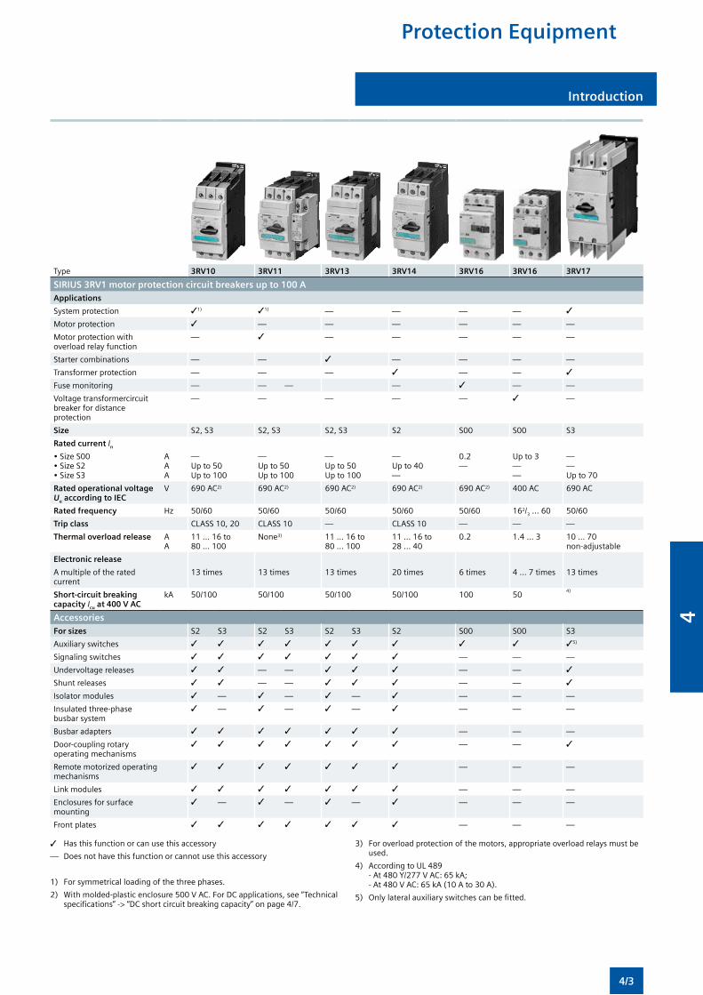
Protection Equipment
Introduction
Type 3RV10 3RV11 3RV13 3RV14 3RV16 3RV16 3RV17
SIRIUS 3RV1 motor protection circuit breakers up to 100 A Applications
System protection 31) 31) — — — — 3
Motor protection 3 — — — — — —
Motor protection with overload relay function
— 3 — — — — —
Starter combinations — — 3 — — — —
Transformer protection — — — 3 — — 3
Fuse monitoring — — — — 3 — —
Voltage transformercircuit breaker for distance protection
— — — — — 3 —
Size S2, S3 S2, S3 S2, S3 S2 S00 S00 S3
Rated current In
• Size S00• Size S2• Size S3
AAA
—Up to 50Up to 100
—Up to 50Up to 100
—Up to 50Up to 100
—Up to 40—
0.2—
Up to 3——
——Up to 70
Rated operational voltage Ue according to IEC
V 690 AC2) 690 AC2) 690 AC2) 690 AC2) 690 AC2) 400 AC 690 AC
Rated frequency Hz 50/60 50/60 50/60 50/60 50/60 162/3 ... 60 50/60
Trip class CLASS 10, 20 CLASS 10 — CLASS 10 — — —
Thermal overload release AA
11 ... 16 to80 ... 100
None3) 11 ... 16 to80 ... 100
11 ... 16 to28 ... 40
0.2 1.4 ... 3 10 ... 70non-adjustable
Electronic release
A multiple of the rated current
13 times 13 times 13 times 20 times 6 times 4 ... 7 times 13 times
Short-circuit breaking capacity Icu at 400 V AC
kA 50/100 50/100 50/100 50/100 100 504)
AccessoriesFor sizes S2 S3 S2 S3 S2 S3 S2 S00 S00 S3
Auxiliary switches 3 3 3 3 3 3 3 3 3 35)
Signaling switches 3 3 3 3 3 3 3 — — —
Undervoltage releases 3 3 — — 3 3 3 — — 3
Shunt releases 3 3 — — 3 3 3 — — 3
Isolator modules 3 — 3 — 3 — 3 — — —
Insulated three-phase busbar system
3 — 3 — 3 — 3 — — —
Busbar adapters 3 3 3 3 3 3 3 — — —
Door-coupling rotary operating mechanisms
3 3 3 3 3 3 3 — — 3
Remote motorized operating mechanisms
3 3 3 3 3 3 3 — — —
Link modules 3 3 3 3 3 3 3 — — —
Enclosures for surface mounting
3 — 3 — 3 — 3 — — —
Front plates 3 3 3 3 3 3 3 — — —
3 Has this function or can use this accessory
— Does not have this function or cannot use this accessory
1) For symmetrical loading of the three phases.
2) With molded-plastic enclosure 500 V AC. For DC applications, see “Technical specifications” -> “DC short circuit breaking capacity” on page 4/7.
3) For overload protection of the motors, appropriate overload relays must be used.
4) According to UL 489 - At 480 Y/277 V AC: 65 kA; - At 480 V AC: 65 kA (10 A to 30 A).
5) Only lateral auxiliary switches can be fitted.
4/3
4
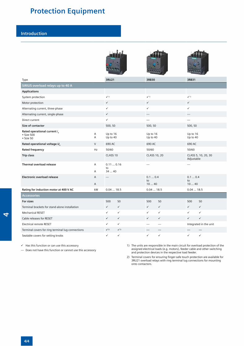
Introduction
Type 3RU21 3RB30 3RB31
SIRIUS overload relays up to 40 A
Applications
System protection 1) 1) 1)
Motor protection
Alternating current, three-phase
Alternating current, single-phase — —
Direct current — —
Size of contactor S00, S0 S00, S0 S00, S0
Rated operational current Ie
• Size S00• Size S0
AA
Up to 16Up to 40
Up to 16Up to 40
Up to 16Up to 40
Rated operational voltage Ue V 690 AC 690 AC 690 AC
Rated frequency Hz 50/60 50/60 50/60
Trip class CLASS 10 CLASS 10, 20 CLASS 5, 10, 20, 30 Adjustable
Thermal overload release A
A
0.11 ... 0.16 to34 ... 40
— —
Electronic overload release A
A
— 0.1 ... 0.4 to10 ... 40
0.1 ... 0.4 to10 ... 40
Rating for induction motor at 400 V AC kW 0.04 ... 18.5 0.04 ... 18.5 0.04 ... 18.5
Accessories
For sizes S00 S0 S00 S0 S00 S0
Terminal brackets for stand-alone installation
Mechanical RESET
Cable releases for RESET
Electrical remote RESET — — Integrated in the unit
Terminal covers for ring terminal lug connections 2) 2) — — — —
Sealable covers for setting knobs
Has this function or can use this accessory
— Does not have this function or cannot use this accessory
1) The units are responsible in the main circuit for overload protection of the assigned electrical loads (e.g. motors), feeder cable and other switching and protection devices in the respective load feeder.
2) Terminal covers for ensuring finger-safe touch protection are available for 3RU21 overload relays with ring terminal lug connections for mounting onto contactors.
Protection Equipment
4/4
4
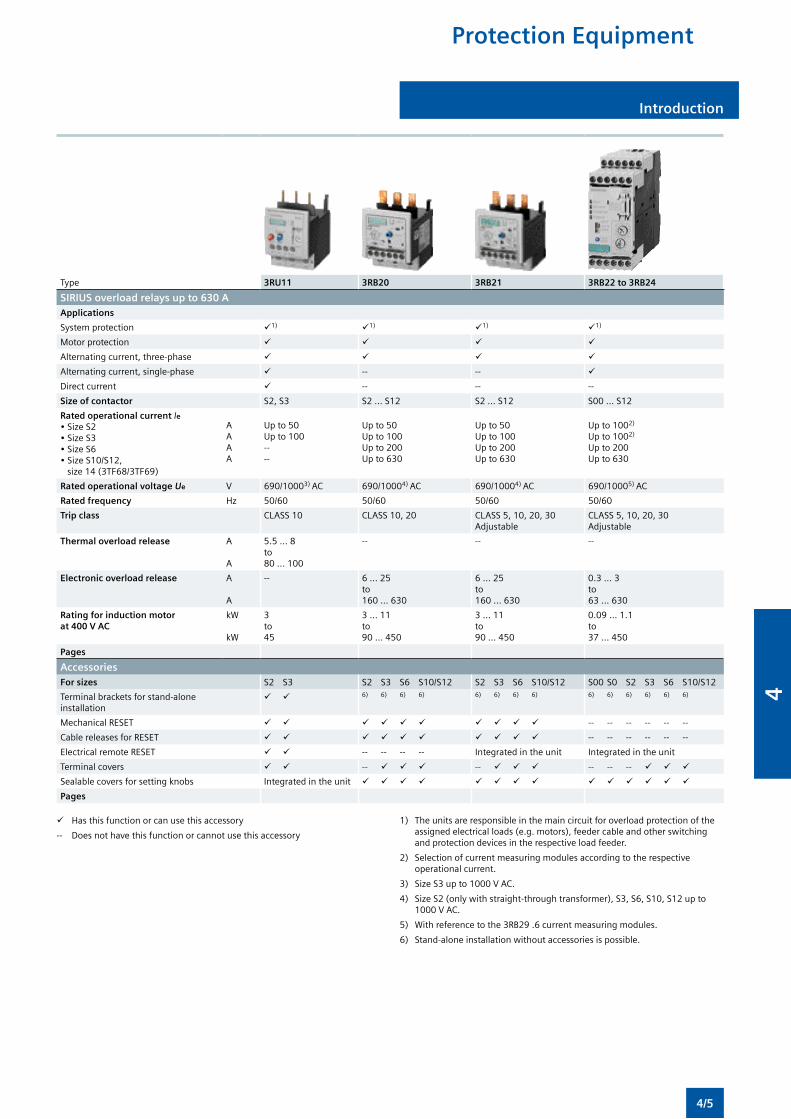
Protection Equipment
Introduction
Type 3RU11 3RB20 3RB21 3RB22 to 3RB24
SIRIUS overload relays up to 630 AApplications
System protection 1) 1) 1) 1)
Motor protection
Alternating current, three-phase
Alternating current, single-phase -- --
Direct current -- -- --
Size of contactor S2, S3 S2 ... S12 S2 ... S12 S00 ... S12
Rated operational current Ie• Size S2 • Size S3 • Size S6 • Size S10/S12, size 14 (3TF68/3TF69)
A A A A
Up to 50 Up to 100 -- --
Up to 50 Up to 100 Up to 200 Up to 630
Up to 50 Up to 100 Up to 200 Up to 630
Up to 1002)
Up to 1002)
Up to 200Up to 630
Rated operational voltage Ue V 690/10003) AC 690/10004) AC 690/10004) AC 690/10005) AC
Rated frequency Hz 50/60 50/60 50/60 50/60
Trip class CLASS 10 CLASS 10, 20 CLASS 5, 10, 20, 30 Adjustable
CLASS 5, 10, 20, 30 Adjustable
Thermal overload release A
A
5.5 ... 8 to 80 ... 100
-- -- --
Electronic overload release A
A
-- 6 ... 25 to 160 ... 630
6 ... 25 to 160 ... 630
0.3 ... 3 to 63 ... 630
Rating for induction motor at 400 V AC
kW
kW
3 to 45
3 ... 11 to 90 ... 450
3 ... 11 to 90 ... 450
0.09 ... 1.1 to 37 ... 450
Pages
AccessoriesFor sizes S2 S3 S2 S3 S6 S10/S12 S2 S3 S6 S10/S12 S00 S0 S2 S3 S6 S10/S12
Terminal brackets for stand-alone installation
6) 6) 6) 6) 6) 6) 6) 6) 6) 6) 6) 6) 6) 6)
Mechanical RESET -- -- -- -- -- --
Cable releases for RESET -- -- -- -- -- --
Electrical remote RESET -- -- -- -- Integrated in the unit Integrated in the unit
Terminal covers -- -- -- -- --
Sealable covers for setting knobs Integrated in the unit
Pages
Has this function or can use this accessory
-- Does not have this function or cannot use this accessory
1) The units are responsible in the main circuit for overload protection of the assigned electrical loads (e.g. motors), feeder cable and other switching and protection devices in the respective load feeder.
2) Selection of current measuring modules according to the respective operational current.
3) Size S3 up to 1000 V AC.
4) Size S2 (only with straight-through transformer), S3, S6, S10, S12 up to 1000 V AC.
5) With reference to the 3RB29 .6 current measuring modules.
6) Stand-alone installation without accessories is possible.
4/5
4
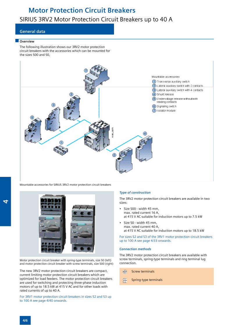
General data
Overview
The following illustration shows our 3RV2 motor protection circuit breakers with the accessories which can be mounted for the sizes S00 and S0,
Mountable accessories for SIRIUS 3RV2 motor protection circuit breakers
Motor protection circuit breaker with spring-type terminals, size S0 (left) and motor protection circuit breaker with screw terminals, size S00 (right)
The new 3RV2 motor protection circuit breakers are compact, current limiting motor protection circuit breakers which are optimized for load feeders. The motor protection circuit breakers are used for switching and protecting three-phase induction motors of up to 18.5 kW at 415 V AC and for other loads with rated currents of up to 40 A.
For 3RV1 motor protection circuit breakers in sizes S2 and S3 up to 100 A see page 4/40 onwards.
Type of construction
The 3RV2 motor protection circuit breakers are available in two sizes:
• Size S00 - width 45 mm, max. rated current 16 A, at 415 V AC suitable for induction motors up to 7.5 kW
• Size S0 - width 45 mm, max. rated current 40 A, at 415 V AC suitable for induction motors up to 18.5 kW
For sizes S2 and S3 of the 3RV1 motor protection circuit breakers up to 100 A see page 4/33 onwards.
Connection methods
The 3RV2 motor protection circuit breakers are available with screw terminals, spring-type terminals and ring terminal lug connection.
Screw terminals
Spring-type terminals
Motor Protection Circuit BreakersSIRIUS 3RV2 Motor Protection Circuit Breakers up to 40 A
General data
4/6
4
Motor Protection Circuit BreakersSIRIUS 3RV2 Motor Protection Circuit Breakers up to 40 A
General data
“Increased safety” type of protection EEx e according to ATEX directive 94/9/EC
The 3RV20 motor protection circuit breakers are suitable for the overload protection of explosion-proof motors with “increased safety” type of protection EEx e;
Order No. scheme
Digit of the Order No. 1st - 3rd 4th 5th 6th 7th 8th 9th 10th 11th 12th 13th 14th 15th 16th
– –
Motor protection circuit breakers 3 R V
SIRIUS Innovation 2
Type of motor protection circuit breakers
Size
Switching capacity
Setting range for overload release
Trip class (CLASS)
Connection methods
With or without auxiliary switch
Special versions
Example 3 R V 2 0 1 1 – 1 A A 1 0
Note:
The Order No. scheme is presented here merely for information purposes and for better understanding of the logic behind the order numbers.
For your orders, please use the order numbers quote in the catalog in the Selection and ordering data.
Application
Operating conditions
3RV2 motor protection circuit breakers are suitable for use in any climate. They are intended for use in enclosed rooms in which no severe operating conditions (such as dust, caustic vapors, hazardous gases) prevail. When installed in dusty and damp areas, suitable enclosures must be provided.
3RV2 motor protection circuit breakers can optionally be fed from the top or from below.
The permissible ambient temperatures, the maximum switching capacities, the tripping currents and other boundary conditions can be found in the technical specifications.
3RV2 motor protection circuit breakers are suitable for operation in IT systems (IT networks). In this case, the different short-circuit breaking capacity in the IT system must be taken into account.
Since operational currents, starting currents and current peaks are different even for motors with identical power ratings due to the inrush current, the motor ratings in the selection tables are only guide values. The specific rated and start-up data of the motor to be protected is always paramount to the choice of the most suitable motor protection circuit breaker. This also applies to motor protection circuit breakers for transformer protection.
Possible uses
The 3RV2 motor protection circuit breakers can be used:
• For short-circuit protection
• For motor protection (also with overload relay function)
• For system protection
• For short-circuit protection for starter combinations
• For transformer protection
• As main control and EMERGENCY-STOP switches
• For operation in IT systems (IT networks)
• For switching of DC currents
• In areas subject to explosion hazard (ATEX)
General data
4/7
4
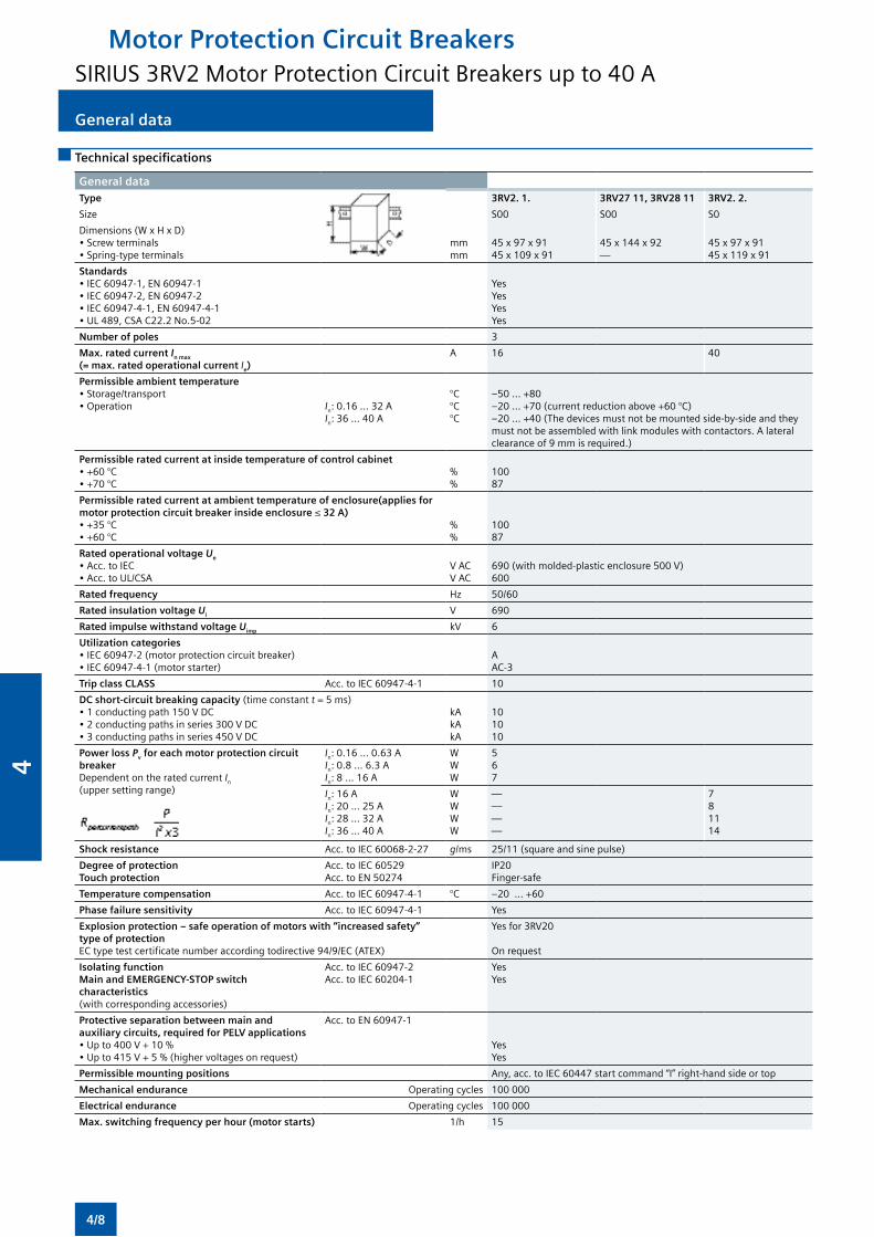
Motor Protection Circuit BreakersSIRIUS 3RV2 Motor Protection Circuit Breakers up to 40 A
General dataGeneral data
Technical specifications
General data Type 3RV2. 1. 3RV27 11, 3RV28 11 3RV2. 2.
Size S00 S00 S0
Dimensions (W x H x D) • Screw terminals• Spring-type terminals
mmmm
45 x 97 x 9145 x 109 x 91
45 x 144 x 92—
45 x 97 x 9145 x 119 x 91
Standards • IEC 60947-1, EN 60947-1• IEC 60947-2, EN 60947-2• IEC 60947-4-1, EN 60947-4-1• UL 489, CSA C22.2 No.5-02
YesYesYesYes
Number of poles 3
Max. rated current In max (= max. rated operational current Ie)
A 16 40
Permissible ambient temperature• Storage/transport• Operation
In: 0.16 ... 32 AIn: 36 ... 40 A
°C°C°C
–50 ... +80–20 ... +70 (current reduction above +60 °C)–20 ... +40 (The devices must not be mounted side-by-side and they must not be assembled with link modules with contactors. A lateral clearance of 9 mm is required.)
Permissible rated current at inside temperature of control cabinet • +60 °C• +70 °C
%%
10087
Permissible rated current at ambient temperature of enclosure(applies for motor protection circuit breaker inside enclosure ≤ 32 A) • +35 °C• +60 °C
%%
10087
Rated operational voltage Ue • Acc. to IEC• Acc. to UL/CSA
V ACV AC
690 (with molded-plastic enclosure 500 V)600
Rated frequency Hz 50/60
Rated insulation voltage Ui V 690
Rated impulse withstand voltage Uimp kV 6
Utilization categories • IEC 60947-2 (motor protection circuit breaker) • IEC 60947-4-1 (motor starter)
AAC-3
Trip class CLASS Acc. to IEC 60947-4-1 10
DC short-circuit breaking capacity (time constant t = 5 ms) • 1 conducting path 150 V DC• 2 conducting paths in series 300 V DC• 3 conducting paths in series 450 V DC
kAkAkA
101010
Power loss Pv for each motor protection circuit breaker Dependent on the rated current In (upper setting range)
In: 0.16 ... 0.63 AIn: 0.8 ... 6.3 AIn: 8 ... 16 A
WWW
567
In: 16 A In: 20 ... 25 AIn: 28 ... 32 AIn: 36 ... 40 A
WWWW
————
781114
Shock resistance Acc. to IEC 60068-2-27 g/ms 25/11 (square and sine pulse)
Degree of protection Touch protection
Acc. to IEC 60529Acc. to EN 50274
IP20Finger-safe
Temperature compensation Acc. to IEC 60947-4-1 °C –20 ... +60
Phase failure sensitivity Acc. to IEC 60947-4-1 Yes
Explosion protection – safe operation of motors with “increased safety” type of protectionEC type test certificate number according todirective 94/9/EC (ATEX)
Yes for 3RV20
On request
Isolating functionMain and EMERGENCY-STOP switch characteristics(with corresponding accessories)
Acc. to IEC 60947-2Acc. to IEC 60204-1
YesYes
Protective separation between main and auxiliary circuits, required for PELV applications• Up to 400 V + 10 %• Up to 415 V + 5 % (higher voltages on request)
Acc. to EN 60947-1 Yes
Yes
Permissible mounting positions Any, acc. to IEC 60447 start command “I” right-hand side or top
Mechanical endurance Operating cycles 100 000
Electrical endurance Operating cycles 100 000
Max. switching frequency per hour (motor starts) 1/h 15
4/8
4
General data General data
Rated data of the auxiliary switches and signaling switchesLateral auxiliary switch with 1 NO + 1 NC, 2 NO, 2 NC, 2 NO + 2 NC
Signaling switch
Transverse auxiliary switch with
1 CO 1 NO + 1 NC, 2 NO
Max. Rated voltage
• Acc. to NEMA (UL) V AC 600 250
• Acc. to NEMA (CSA) V AC 600 250
Uninterrupted current A 10 10 5 2.5
Switching capacity 1 NO + 1 NC, 2 NO, 2 NC: A600, Q300;2 NO + 2 NC: A300, Q300
A600, Q300 B600, R300 C300, R300
Front transverse auxiliary switchesSwitching capacity for different voltages
1 CO 1 NO + 1 NC, 2 NO
Rated operational current Ie
• At AC-15, alternating voltage - 24 V - 230 V - 400 V - 690 V
AAAA
431.50.5
20.5——
• At AC-12 = Ith, alternating voltage - 24 V - 230 V - 400 V - 690 V
AAAA
10101010
2.52.5——
• At DC-13, direct voltage L/R 200 ms - 24 V - 48 V - 60 V - 110 V - 220 V
AAAAA
1——0.220.1
10.30.15——
Minimum load capacity VmA
171
Front transverse solid-state compatible auxiliary switches Switching capacity for different voltages
1 CO
Rated operational voltage Ue Alternating voltage V 125
Rated operational current Ie/AC-14 at Ue = 125 V A 0.1
Rated operational voltage Ue Direct voltage L/R 200 ms V 60
Rated operational current Ie/DC-13 at Ue = 60 V A 0.3
Minimum load capacity VmA
51
Lateral auxiliary switches with signaling switchSwitching capacity for different voltages: Lateral auxiliary switch with 1 NO + 1 NC, 2 NO, 2 NC, 2 NO + 2 NCSignaling switch
Rated operational current Ie
• At AC-15, alternating voltage - 24 V - 230 V - 400 V - 690 V
AAAA
6431
• At AC-12 = Ith, alternating voltage - 24 V - 230 V - 400 V - 690 V
AAAA
10101010
• At DC-13, direct voltage L/R 200 ms - 24 V - 110 V - 220 V - 440 V
AAAA
20.50.250.1
Minimum load capacity VmA
171
Motor Protection Circuit BreakersSIRIUS 3RV2 Motor Protection Circuit Breakers up to 40 A
4/9
4
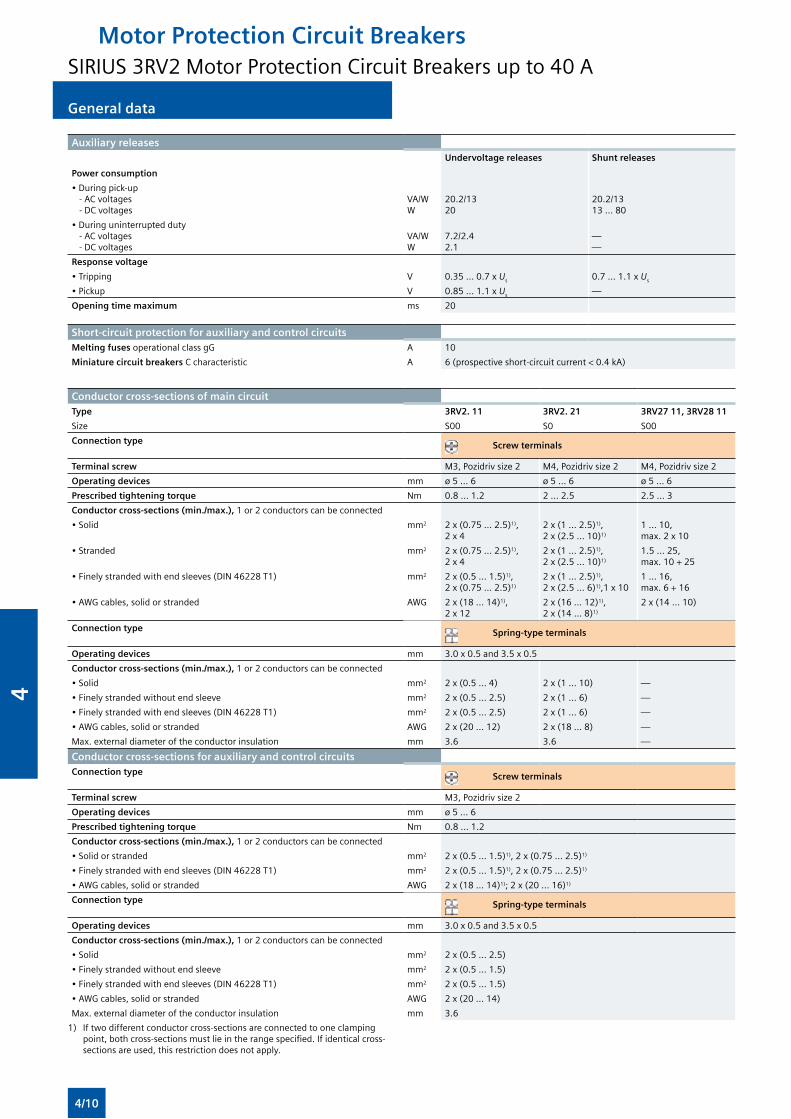
General dataGeneral data
Auxiliary releasesUndervoltage releases Shunt releases
Power consumption
• During pick-up - AC voltages - DC voltages
VA/WW
20.2/1320
20.2/1313 ... 80
• During uninterrupted duty - AC voltages - DC voltages
VA/WW
7.2/2.42.1
——
Response voltage
• Tripping V 0.35 ... 0.7 x Us 0.7 ... 1.1 x Us
• Pickup V 0.85 ... 1.1 x Us —
Opening time maximum ms 20
Short-circuit protection for auxiliary and control circuitsMelting fuses operational class gG A 10
Miniature circuit breakers C characteristic A 6 (prospective short-circuit current < 0.4 kA)
Conductor cross-sections of main circuitType 3RV2. 11 3RV2. 21 3RV27 11, 3RV28 11
Size S00 S0 S00
Connection type Screw terminals
Terminal screw M3, Pozidriv size 2 M4, Pozidriv size 2 M4, Pozidriv size 2
Operating devices mm ø 5 ... 6 ø 5 ... 6 ø 5 ... 6
Prescribed tightening torque Nm 0.8 ... 1.2 2 ... 2.5 2.5 ... 3
Conductor cross-sections (min./max.), 1 or 2 conductors can be connected
• Solid mm2 2 x (0.75 ... 2.5)1),2 x 4
2 x (1 ... 2.5)1), 2 x (2.5 ... 10)1)
1 ... 10,max. 2 x 10
• Stranded mm2 2 x (0.75 ... 2.5)1),2 x 4
2 x (1 ... 2.5)1), 2 x (2.5 ... 10)1)
1.5 ... 25,max. 10 + 25
• Finely stranded with end sleeves (DIN 46228 T1) mm2 2 x (0.5 ... 1.5)1), 2 x (0.75 ... 2.5)1)
2 x (1 ... 2.5)1), 2 x (2.5 ... 6)1),1 x 10
1 ... 16,max. 6 + 16
• AWG cables, solid or stranded AWG 2 x (18 ... 14)1),2 x 12
2 x (16 ... 12)1), 2 x (14 ... 8)1)
2 x (14 ... 10)
Connection type Spring-type terminals
Operating devices mm 3.0 x 0.5 and 3.5 x 0.5
Conductor cross-sections (min./max.), 1 or 2 conductors can be connected
• Solid mm2 2 x (0.5 ... 4) 2 x (1 ... 10) —
• Finely stranded without end sleeve mm2 2 x (0.5 ... 2.5) 2 x (1 ... 6) —
• Finely stranded with end sleeves (DIN 46228 T1) mm2 2 x (0.5 ... 2.5) 2 x (1 ... 6) —
• AWG cables, solid or stranded AWG 2 x (20 ... 12) 2 x (18 ... 8) —
Max. external diameter of the conductor insulation mm 3.6 3.6 —
Conductor cross-sections for auxiliary and control circuitsConnection type Screw terminals
Terminal screw M3, Pozidriv size 2
Operating devices mm ø 5 ... 6
Prescribed tightening torque Nm 0.8 ... 1.2
Conductor cross-sections (min./max.), 1 or 2 conductors can be connected
• Solid or stranded mm2 2 x (0.5 ... 1.5)1), 2 x (0.75 ... 2.5)1)
• Finely stranded with end sleeves (DIN 46228 T1) mm2 2 x (0.5 ... 1.5)1), 2 x (0.75 ... 2.5)1)
• AWG cables, solid or stranded AWG 2 x (18 ... 14)1); 2 x (20 ... 16)1)
Connection type Spring-type terminals
Operating devices mm 3.0 x 0.5 and 3.5 x 0.5
Conductor cross-sections (min./max.), 1 or 2 conductors can be connected
• Solid mm2 2 x (0.5 ... 2.5)
• Finely stranded without end sleeve mm2 2 x (0.5 ... 1.5)
• Finely stranded with end sleeves (DIN 46228 T1) mm2 2 x (0.5 ... 1.5)
• AWG cables, solid or stranded AWG 2 x (20 ... 14)
Max. external diameter of the conductor insulation mm 3.6
1) If two different conductor cross-sections are connected to one clamping point, both cross-sections must lie in the range specified. If identical cross-sections are used, this restriction does not apply.
Motor Protection Circuit BreakersSIRIUS 3RV2 Motor Protection Circuit Breakers up to 40 A
4/10
4
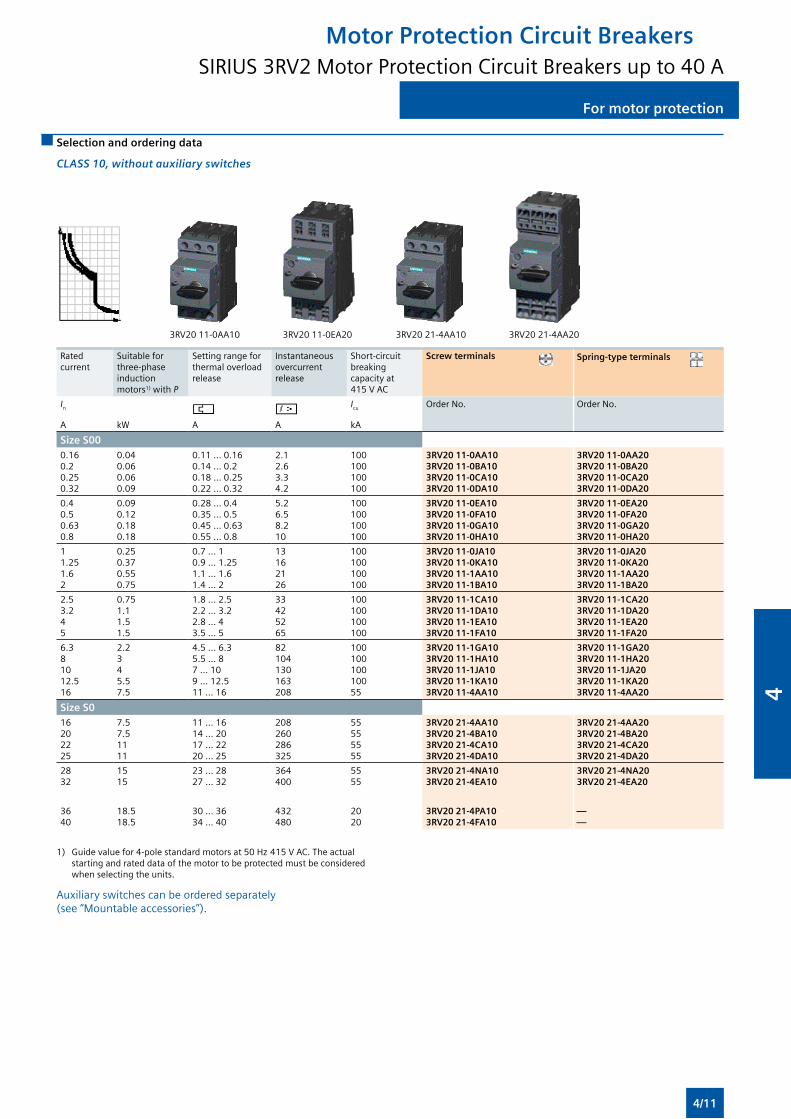
For motor protection For motor protection
Selection and ordering data
CLASS 10, without auxiliary switches
3RV20 11-0AA10 3RV20 11-0EA20 3RV20 21-4AA10 3RV20 21-4AA20
Rated current
Suitable for three-phase induction motors1) with P
Setting range for thermal overload release
Instantaneous overcurrent release
Short-circuit breaking capacity at 415 V AC
Screw terminals Spring-type terminals
In Icu Order No. Order No.
A kW A A kA
Size S000.160.20.250.32
0.040.060.060.09
0.11 ... 0.160.14 ... 0.20.18 ... 0.250.22 ... 0.32
2.12.63.34.2
100100100100
3RV20 11-0AA103RV20 11-0BA103RV20 11-0CA103RV20 11-0DA10
3RV20 11-0AA203RV20 11-0BA203RV20 11-0CA203RV20 11-0DA20
0.40.50.630.8
0.090.120.180.18
0.28 ... 0.40.35 ... 0.50.45 ... 0.630.55 ... 0.8
5.26.58.210
100100100100
3RV20 11-0EA103RV20 11-0FA103RV20 11-0GA103RV20 11-0HA10
3RV20 11-0EA203RV20 11-0FA203RV20 11-0GA203RV20 11-0HA20
11.251.62
0.250.370.550.75
0.7 ... 10.9 ... 1.251.1 ... 1.61.4 ... 2
13162126
100100100100
3RV20 11-0JA103RV20 11-0KA103RV20 11-1AA103RV20 11-1BA10
3RV20 11-0JA203RV20 11-0KA203RV20 11-1AA203RV20 11-1BA20
2.53.245
0.751.11.51.5
1.8 ... 2.52.2 ... 3.22.8 ... 43.5 ... 5
33425265
100100100100
3RV20 11-1CA103RV20 11-1DA103RV20 11-1EA103RV20 11-1FA10
3RV20 11-1CA203RV20 11-1DA203RV20 11-1EA203RV20 11-1FA20
6.381012.516
2.2345.57.5
4.5 ... 6.35.5 ... 87 ... 109 ... 12.511 ... 16
82104130163208
10010010010055
3RV20 11-1GA103RV20 11-1HA103RV20 11-1JA103RV20 11-1KA103RV20 11-4AA10
3RV20 11-1GA203RV20 11-1HA203RV20 11-1JA203RV20 11-1KA203RV20 11-4AA20
Size S016202225
7.57.51111
11 ... 1614 ... 2017 ... 2220 ... 25
208260286325
55555555
3RV20 21-4AA103RV20 21-4BA103RV20 21-4CA103RV20 21-4DA10
3RV20 21-4AA203RV20 21-4BA203RV20 21-4CA203RV20 21-4DA20
2832
1515
23 ... 2827 ... 32
364400
5555
3RV20 21-4NA103RV20 21-4EA10
3RV20 21-4NA203RV20 21-4EA20
3640
18.518.5
30 ... 3634 ... 40
432480
2020
3RV20 21-4PA103RV20 21-4FA10
——
1) Guide value for 4-pole standard motors at 50 Hz 415 V AC. The actual starting and rated data of the motor to be protected must be considered when selecting the units.
Auxiliary switches can be ordered separately (see “Mountable accessories”).
Motor Protection Circuit BreakersSIRIUS 3RV2 Motor Protection Circuit Breakers up to 40 A
4/11
4
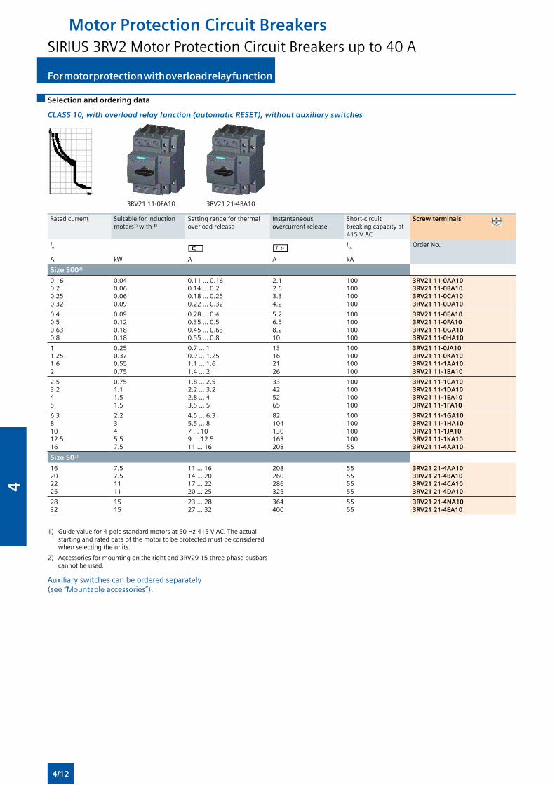
For motor protection with overload relay functionFor motor protection with overload relay function
Selection and ordering data
CLASS 10, with overload relay function (automatic RESET), without auxiliary switches
3RV21 11-0FA10 3RV21 21-4BA10
Rated current Suitable for induction motors1) with P
Setting range for thermal overload release
Instantaneous overcurrent release
Short-circuit breaking capacity at 415 V AC
Screw terminals
In Icu Order No.
A kW A A kA
Size S002) 0.160.20.250.32
0.040.060.060.09
0.11 ... 0.160.14 ... 0.20.18 ... 0.250.22 ... 0.32
2.12.63.34.2
100100100100
3RV21 11-0AA10 3RV21 11-0BA10 3RV21 11-0CA10 3RV21 11-0DA10
0.40.50.630.8
0.090.120.180.18
0.28 ... 0.40.35 ... 0.50.45 ... 0.630.55 ... 0.8
5.26.58.210
100100100100
3RV21 11-0EA10 3RV21 11-0FA10 3RV21 11-0GA10 3RV21 11-0HA10
11.251.62
0.250.370.550.75
0.7 ... 10.9 ... 1.251.1 ... 1.61.4 ... 2
13162126
100100100100
3RV21 11-0JA10 3RV21 11-0KA10 3RV21 11-1AA10 3RV21 11-1BA10
2.53.245
0.751.11.51.5
1.8 ... 2.52.2 ... 3.22.8 ... 43.5 ... 5
33425265
100100100100
3RV21 11-1CA10 3RV21 11-1DA10 3RV21 11-1EA10 3RV21 11-1FA10
6.381012.516
2.2345.57.5
4.5 ... 6.35.5 ... 87 ... 109 ... 12.511 ... 16
82104130163208
10010010010055
3RV21 11-1GA10 3RV21 11-1HA10 3RV21 11-1JA10 3RV21 11-1KA10 3RV21 11-4AA10
Size S02)
16202225
7.57.51111
11 ... 1614 ... 2017 ... 2220 ... 25
208260286325
55555555
3RV21 21-4AA10 3RV21 21-4BA10 3RV21 21-4CA10 3RV21 21-4DA10
2832
1515
23 ... 2827 ... 32
364400
5555
3RV21 21-4NA103RV21 21-4EA10
1) Guide value for 4-pole standard motors at 50 Hz 415 V AC. The actual starting and rated data of the motor to be protected must be considered when selecting the units.
2) Accessories for mounting on the right and 3RV29 15 three-phase busbars cannot be used.
Auxiliary switches can be ordered separately (see “Mountable accessories”).
Motor Protection Circuit BreakersSIRIUS 3RV2 Motor Protection Circuit Breakers up to 40 A
4/12
4
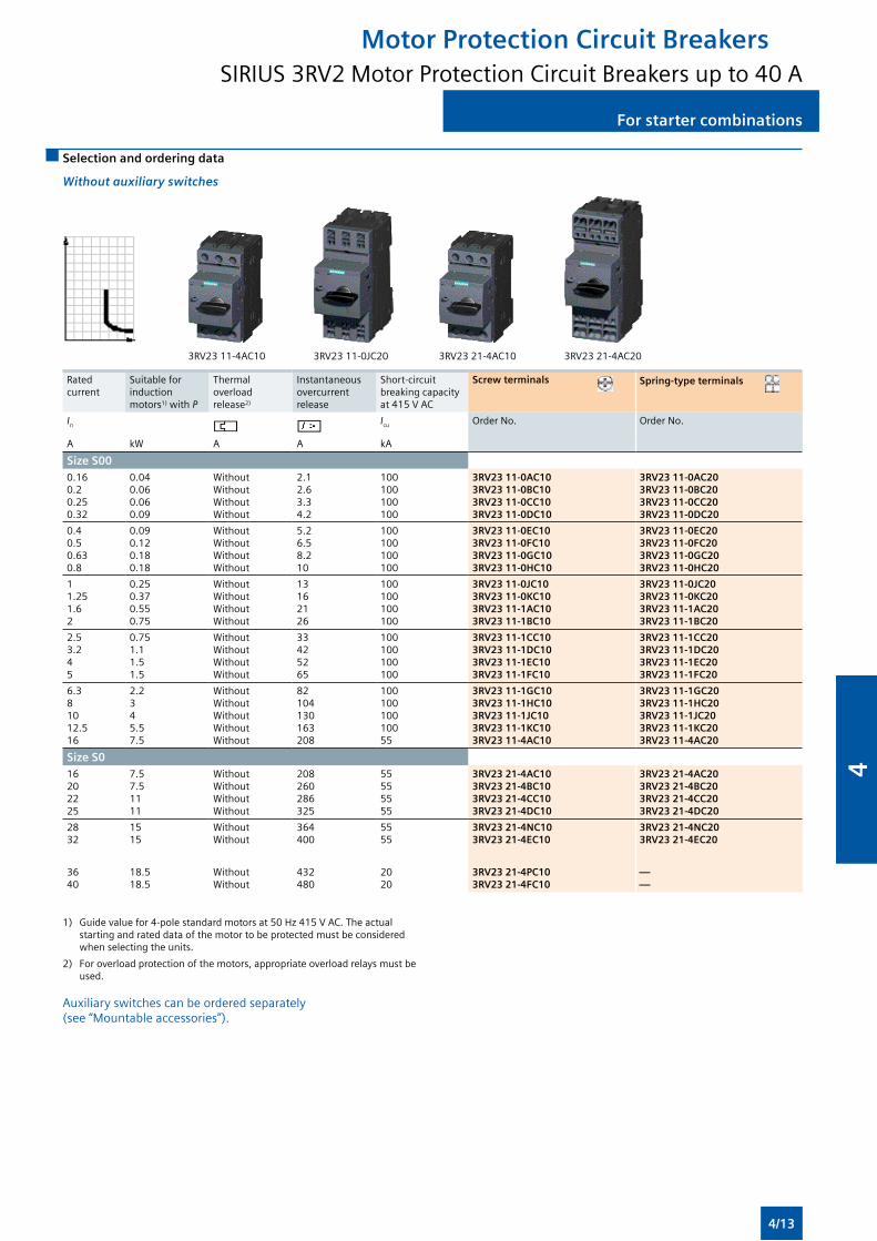
For starter combinations For starter combinations
Selection and ordering data
Without auxiliary switches
3RV23 11-4AC10 3RV23 11-0JC20 3RV23 21-4AC10 3RV23 21-4AC20
Rated current
Suitable for induction motors1) with P
Thermal overload release2)
Instantaneous overcurrent release
Short-circuit breaking capacity at 415 V AC
Screw terminals Spring-type terminals
In Icu Order No. Order No.
A kW A A kA
Size S00 0.160.20.250.32
0.040.060.060.09
WithoutWithoutWithoutWithout
2.12.63.34.2
100100100100
3RV23 11-0AC10 3RV23 11-0BC10 3RV23 11-0CC10 3RV23 11-0DC10
3RV23 11-0AC20 3RV23 11-0BC20 3RV23 11-0CC20 3RV23 11-0DC20
0.40.50.630.8
0.090.120.180.18
WithoutWithoutWithoutWithout
5.26.58.210
100100100100
3RV23 11-0EC10 3RV23 11-0FC10 3RV23 11-0GC10 3RV23 11-0HC10
3RV23 11-0EC20 3RV23 11-0FC20 3RV23 11-0GC20 3RV23 11-0HC20
11.251.62
0.250.370.550.75
WithoutWithoutWithoutWithout
13162126
100100100100
3RV23 11-0JC10 3RV23 11-0KC10 3RV23 11-1AC10 3RV23 11-1BC10
3RV23 11-0JC20 3RV23 11-0KC20 3RV23 11-1AC20 3RV23 11-1BC20
2.53.245
0.751.11.51.5
WithoutWithoutWithoutWithout
33425265
100100100100
3RV23 11-1CC10 3RV23 11-1DC10 3RV23 11-1EC10 3RV23 11-1FC10
3RV23 11-1CC20 3RV23 11-1DC20 3RV23 11-1EC20 3RV23 11-1FC20
6.381012.516
2.2345.57.5
WithoutWithoutWithoutWithoutWithout
82104130163208
10010010010055
3RV23 11-1GC10 3RV23 11-1HC10 3RV23 11-1JC10 3RV23 11-1KC10 3RV23 11-4AC10
3RV23 11-1GC20 3RV23 11-1HC20 3RV23 11-1JC20 3RV23 11-1KC20 3RV23 11-4AC20
Size S0 16202225
7.57.51111
WithoutWithoutWithoutWithout
208260286325
55555555
3RV23 21-4AC10 3RV23 21-4BC10 3RV23 21-4CC10 3RV23 21-4DC10
3RV23 21-4AC20 3RV23 21-4BC20 3RV23 21-4CC20 3RV23 21-4DC20
2832
1515
WithoutWithout
364400
5555
3RV23 21-4NC103RV23 21-4EC10
3RV23 21-4NC203RV23 21-4EC20
3640
18.518.5
WithoutWithout
432480
2020
3RV23 21-4PC103RV23 21-4FC10
——
1) Guide value for 4-pole standard motors at 50 Hz 415 V AC. The actual starting and rated data of the motor to be protected must be considered when selecting the units.
2) For overload protection of the motors, appropriate overload relays must be used.
Auxiliary switches can be ordered separately (see “Mountable accessories”).
Motor Protection Circuit BreakersSIRIUS 3RV2 Motor Protection Circuit Breakers up to 40 A
4/13
4
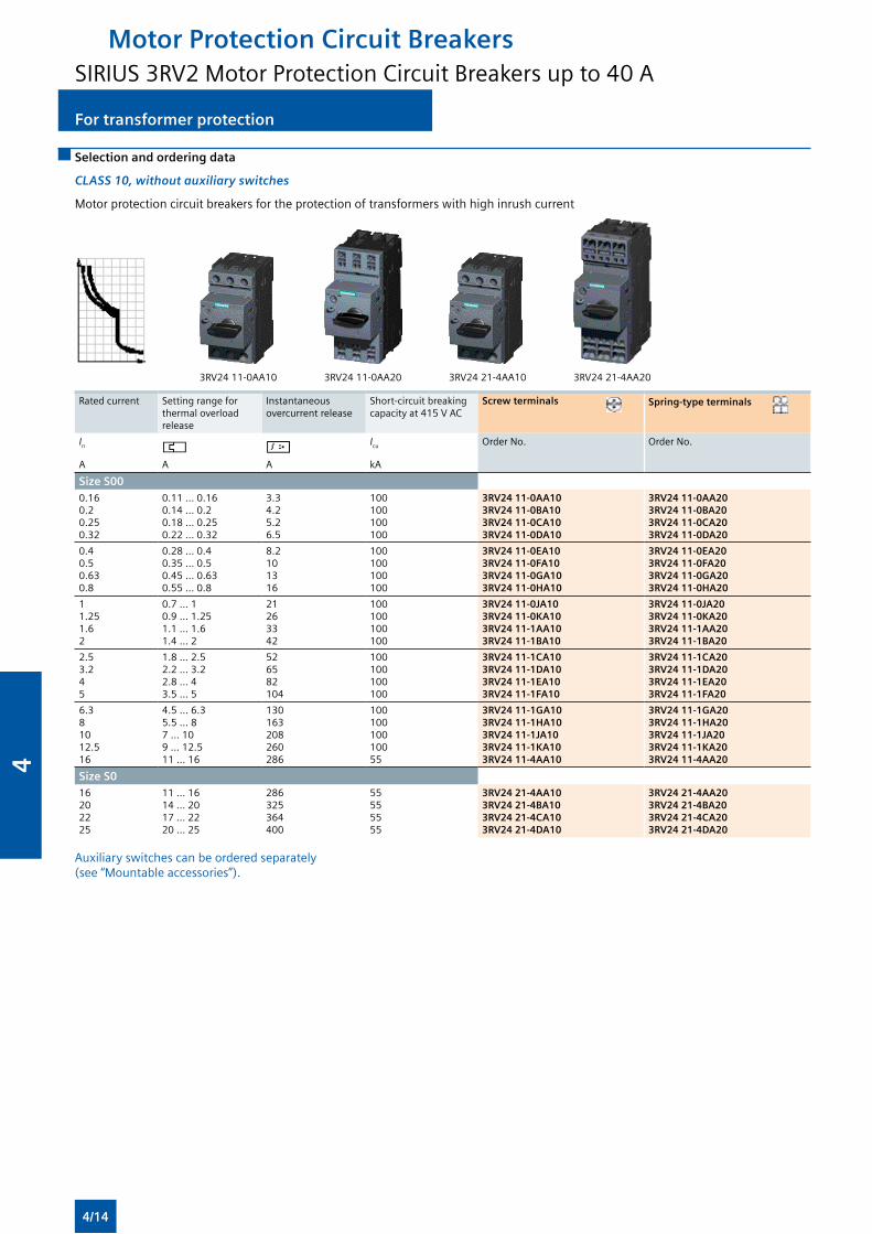
For transformer protectionFor transformer protection
Selection and ordering data
CLASS 10, without auxiliary switches
Motor protection circuit breakers for the protection of transformers with high inrush current
3RV24 11-0AA10 3RV24 11-0AA20 3RV24 21-4AA10 3RV24 21-4AA20
Rated current Setting range for thermal overload release
Instantaneous overcurrent release
Short-circuit breaking capacity at 415 V AC
Screw terminals Spring-type terminals
In Icu Order No. Order No.
A A A kA
Size S00 0.160.20.250.32
0.11 ... 0.160.14 ... 0.20.18 ... 0.250.22 ... 0.32
3.34.25.26.5
100100100100
3RV24 11-0AA10 3RV24 11-0BA10 3RV24 11-0CA10 3RV24 11-0DA10
3RV24 11-0AA20 3RV24 11-0BA20 3RV24 11-0CA20 3RV24 11-0DA20
0.40.50.630.8
0.28 ... 0.40.35 ... 0.50.45 ... 0.630.55 ... 0.8
8.2101316
100100100100
3RV24 11-0EA10 3RV24 11-0FA10 3RV24 11-0GA10 3RV24 11-0HA10
3RV24 11-0EA20 3RV24 11-0FA20 3RV24 11-0GA20 3RV24 11-0HA20
11.251.62
0.7 ... 10.9 ... 1.251.1 ... 1.61.4 ... 2
21263342
100100100100
3RV24 11-0JA10 3RV24 11-0KA10 3RV24 11-1AA10 3RV24 11-1BA10
3RV24 11-0JA20 3RV24 11-0KA20 3RV24 11-1AA20 3RV24 11-1BA20
2.53.245
1.8 ... 2.52.2 ... 3.22.8 ... 43.5 ... 5
526582104
100100100100
3RV24 11-1CA10 3RV24 11-1DA10 3RV24 11-1EA10 3RV24 11-1FA10
3RV24 11-1CA20 3RV24 11-1DA20 3RV24 11-1EA20 3RV24 11-1FA20
6.381012.516
4.5 ... 6.35.5 ... 87 ... 109 ... 12.511 ... 16
130163208260286
10010010010055
3RV24 11-1GA10 3RV24 11-1HA10 3RV24 11-1JA10 3RV24 11-1KA10 3RV24 11-4AA10
3RV24 11-1GA20 3RV24 11-1HA20 3RV24 11-1JA20 3RV24 11-1KA20 3RV24 11-4AA20
Size S0 16202225
11 ... 1614 ... 2017 ... 2220 ... 25
286325364400
55555555
3RV24 21-4AA10 3RV24 21-4BA10 3RV24 21-4CA103RV24 21-4DA10
3RV24 21-4AA20 3RV24 21-4BA20 3RV24 21-4CA203RV24 21-4DA20
Auxiliary switches can be ordered separately (see “Mountable accessories”).
Motor Protection Circuit BreakersSIRIUS 3RV2 Motor Protection Circuit Breakers up to 40 A
4/14
4
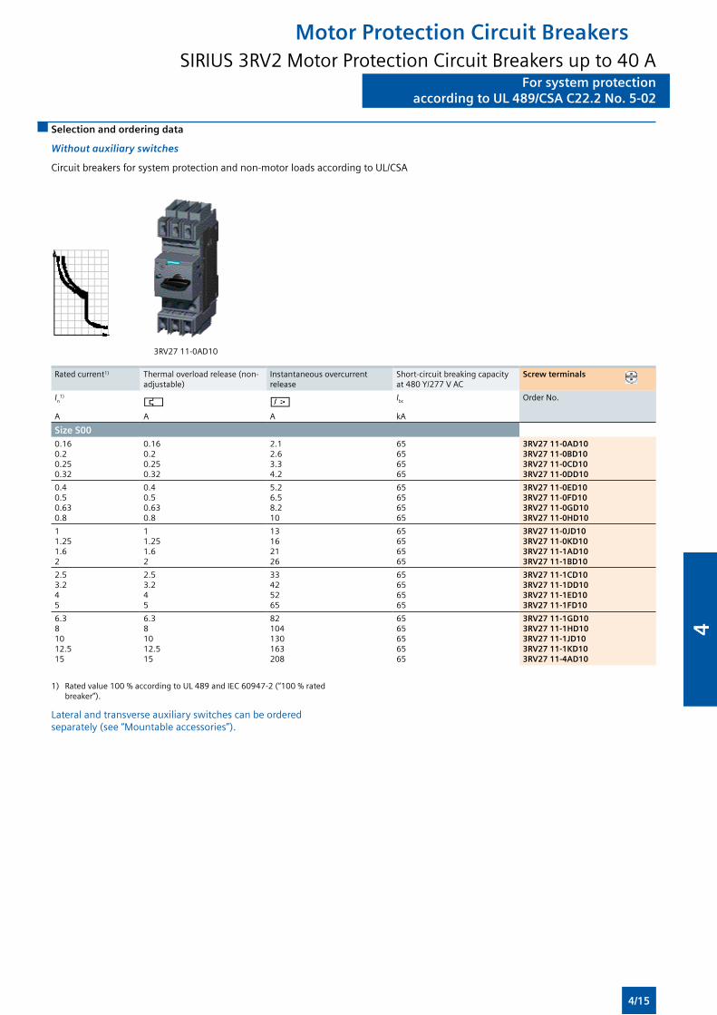
For system protectionaccording to UL 489/CSA C22.2 No. 5-02
For system protectionaccording to UL 489/CSA C22.2 No. 5-02
Selection and ordering data
Without auxiliary switches
Circuit breakers for system protection and non-motor loads according to UL/CSA
3RV27 11-0AD10
Rated current1) Thermal overload release (non-adjustable)
Instantaneous overcurrent release
Short-circuit breaking capacity at 480 Y/277 V AC
Screw terminals
In1) Ibc Order No.
A A A kA
Size S000.160.20.250.32
0.160.20.250.32
2.12.63.34.2
65656565
3RV27 11-0AD10 3RV27 11-0BD10 3RV27 11-0CD10 3RV27 11-0DD10
0.40.50.630.8
0.40.50.630.8
5.26.58.210
65656565
3RV27 11-0ED10 3RV27 11-0FD10 3RV27 11-0GD10 3RV27 11-0HD10
11.251.62
11.251.62
13162126
65656565
3RV27 11-0JD10 3RV27 11-0KD10 3RV27 11-1AD10 3RV27 11-1BD10
2.53.245
2.53.245
33425265
65656565
3RV27 11-1CD10 3RV27 11-1DD10 3RV27 11-1ED10 3RV27 11-1FD10
6.381012.515
6.381012.515
82104130163208
6565656565
3RV27 11-1GD10 3RV27 11-1HD10 3RV27 11-1JD10 3RV27 11-1KD10 3RV27 11-4AD10
1) Rated value 100 % according to UL 489 and IEC 60947-2 (“100 % rated breaker”).
Lateral and transverse auxiliary switches can be ordered separately (see “Mountable accessories”).
Motor Protection Circuit BreakersSIRIUS 3RV2 Motor Protection Circuit Breakers up to 40 A
4/15
4
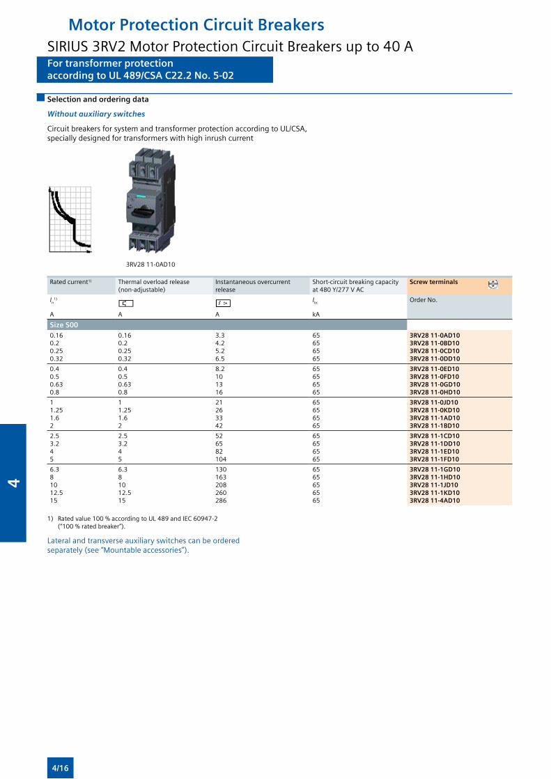
For transformer protectionaccording to UL 489/CSA C22.2 No. 5-02
For transformer protectionaccording to UL 489/CSA C22.2 No. 5-02
Selection and ordering data
Without auxiliary switches
Circuit breakers for system and transformer protection according to UL/CSA, specially designed for transformers with high inrush current
3RV28 11-0AD10
Rated current1) Thermal overload release (non-adjustable)
Instantaneous overcurrent release
Short-circuit breaking capacity at 480 Y/277 V AC
Screw terminals
In1) Ibc Order No.
A A A kA
Size S000.160.20.250.32
0.160.20.250.32
3.34.25.26.5
65656565
3RV28 11-0AD10 3RV28 11-0BD10 3RV28 11-0CD10 3RV28 11-0DD10
0.40.50.630.8
0.40.50.630.8
8.2101316
65656565
3RV28 11-0ED10 3RV28 11-0FD10 3RV28 11-0GD10 3RV28 11-0HD10
11.251.62
11.251.62
21263342
65656565
3RV28 11-0JD10 3RV28 11-0KD10 3RV28 11-1AD10 3RV28 11-1BD10
2.53.245
2.53.245
526582104
65656565
3RV28 11-1CD10 3RV28 11-1DD10 3RV28 11-1ED10 3RV28 11-1FD10
6.381012.515
6.381012.515
130163208260286
6565656565
3RV28 11-1GD10 3RV28 11-1HD10 3RV28 11-1JD10 3RV28 11-1KD10 3RV28 11-4AD10
1) Rated value 100 % according to UL 489 and IEC 60947-2 (“100 % rated breaker”).
Lateral and transverse auxiliary switches can be ordered separately (see “Mountable accessories”).
Motor Protection Circuit BreakersSIRIUS 3RV2 Motor Protection Circuit Breakers up to 40 A
4/16
4
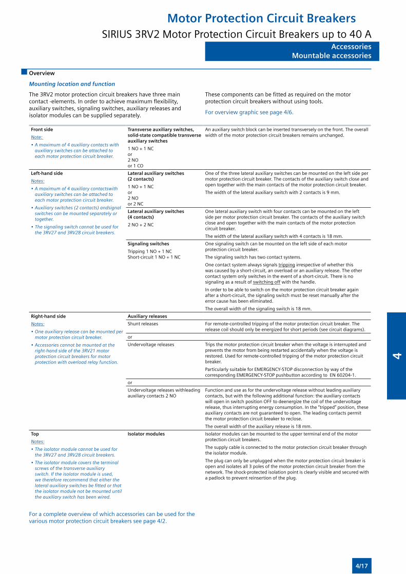
AccessoriesMountable accessories
AccessoriesMountable accessories
Overview
Mounting location and function
The 3RV2 motor protection circuit breakers have three main contact -elements. In order to achieve maximum flexibility, auxiliary switches, signaling switches, auxiliary releases and isolator modules can be supplied separately.
These components can be fitted as required on the motor protection circuit breakers without using tools.
For overview graphic see page 4/6.
Front side
Note:
•Amaximumof4auxiliarycontactswithauxiliaryswitchescanbeattachedtoeach motor protection circuit breaker.
Transverse auxiliary switches, solid-state compatible transverse auxiliary switches
1 NO + 1 NC or 2 NO or 1 CO
An auxiliary switch block can be inserted transversely on the front. The overall width of the motor protection circuit breakers remains unchanged.
Left-hand side
Notes:
•Amaximumof4auxiliarycontactswithauxiliaryswitchescanbeattachedtoeach motor protection circuit breaker.
•Auxiliaryswitches(2contacts)andsignalswitchescanbemountedseparatelyortogether.
•Thesignalingswitchcannotbeusedforthe3RV27and3RV28circuitbreakers.
Lateral auxiliary switches (2 contacts)
1 NO + 1 NC or 2 NO or 2 NC
One of the three lateral auxiliary switches can be mounted on the left side per motor protection circuit breaker. The contacts of the auxiliary switch close and open together with the main contacts of the motor protection circuit breaker.
The width of the lateral auxiliary switch with 2 contacts is 9 mm.
Lateral auxiliary switches (4 contacts)
2 NO + 2 NC
One lateral auxiliary switch with four contacts can be mounted on the left side per motor protection circuit breaker. The contacts of the auxiliary switch close and open together with the main contacts of the motor protection circuit breaker.
The width of the lateral auxiliary switch with 4 contacts is 18 mm.
Signaling switches
Tripping 1 NO + 1 NC Short-circuit 1 NO + 1 NC
One signaling switch can be mounted on the left side of each motor protection circuit breaker.
The signaling switch has two contact systems.
One contact system always signals tripping irrespective of whether this was caused by a short-circuit, an overload or an auxiliary release. The other contact system only switches in the event of a short-circuit. There is no signaling as a result of switching off with the handle.
In order to be able to switch on the motor protection circuit breaker again after a short-circuit, the signaling switch must be reset manually after the error cause has been eliminated.
The overall width of the signaling switch is 18 mm.
Right-hand side
Notes:
•Oneauxiliaryreleasecanbemountedpermotor protection circuit breaker.
•Accessoriescannotbemountedattheright-handsideofthe3RV21motorprotection circuit breakers for motor protectionwithoverloadrelayfunction.
Auxiliary releases
Shunt releases For remote-controlled tripping of the motor protection circuit breaker. The release coil should only be energized for short periods (see circuit diagrams).
or
Undervoltage releases Trips the motor protection circuit breaker when the voltage is interrupted and prevents the motor from being restarted accidentally when the voltage is restored. Used for remote-controlled tripping of the motor protection circuit breaker.
Particularly suitable for EMERGENCY-STOP disconnection by way of the corresponding EMERGENCY-STOP pushbutton according to EN 60204-1.
or
Undervoltage releases withleading auxiliary contacts 2 NO
Function and use as for the undervoltage release without leading auxiliary contacts, but with the following additional function: the auxiliary contacts will open in switch position OFF to deenergize the coil of the undervoltage release, thus interrupting energy consumption. In the “tripped” position, these auxiliary contacts are not guaranteed to open. The leading contacts permit the motor protection circuit breaker to reclose.
The overall width of the auxiliary release is 18 mm.
Top
Notes:
•Theisolatormodulecannotbeusedforthe3RV27and3RV28circuitbreakers.
•Theisolatormodulecoverstheterminalscrewsofthetransverseauxiliaryswitch.Iftheisolatormoduleisused,wethereforerecommendthateitherthelateralauxiliaryswitchesbefittedorthatthe isolator module not be mounted until theauxiliaryswitchhasbeenwired.
Isolator modules Isolator modules can be mounted to the upper terminal end of the motor protection circuit breakers.
The supply cable is connected to the motor protection circuit breaker through the isolator module.
The plug can only be unplugged when the motor protection circuit breaker is open and isolates all 3 poles of the motor protection circuit breaker from the network. The shock-protected isolation point is clearly visible and secured with a padlock to prevent reinsertion of the plug.
For a complete overview of which accessories can be used for the various motor protection circuit breakers see page 4/2.
Motor Protection Circuit BreakersSIRIUS 3RV2 Motor Protection Circuit Breakers up to 40 A
4/17
4
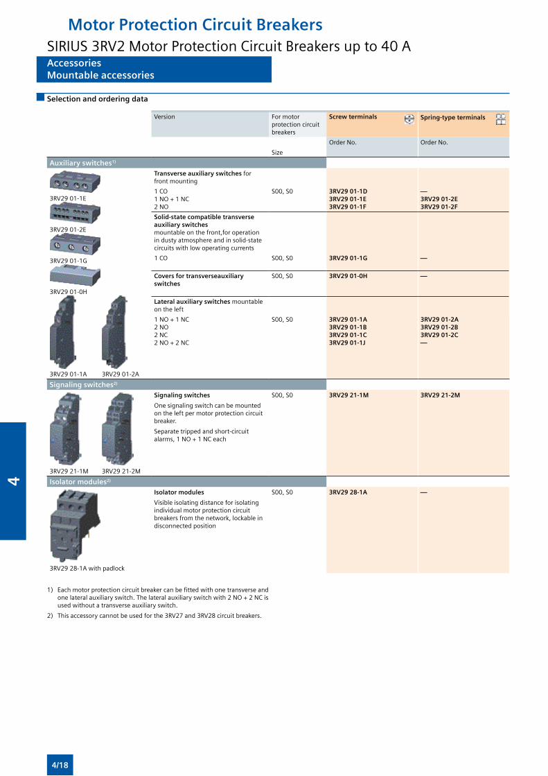
AccessoriesMountable accessories
AccessoriesMountable accessories
Selection and ordering data
Version For motor protection circuit breakers
Screw terminals Spring-type terminals
Order No. Order No.
Size
Auxiliary switches1)
3RV29 01-1E
3RV29 01-2E
3RV29 01-1G
3RV29 01-0H
3RV29 01-1A 3RV29 01-2A
Transverse auxiliary switches for front mounting
1 CO 1 NO + 1 NC 2 NO
S00, S0 3RV29 01-1D3RV29 01-1E3RV29 01-1F
—3RV29 01-2E3RV29 01-2F
Solid-state compatible transverse auxiliary switches mountable on the front,for operation in dusty atmosphere and in solid-state circuits with low operating currents
1 CO S00, S0 3RV29 01-1G —
Covers for transverseauxiliary switches
S00, S0 3RV29 01-0H —
Lateral auxiliary switches mountable on the left
1 NO + 1 NC2 NO2 NC2 NO + 2 NC
S00, S0 3RV29 01-1A3RV29 01-1B3RV29 01-1C3RV29 01-1J
3RV29 01-2A3RV29 01-2B3RV29 01-2C—
Signaling switches2)
3RV29 21-1M 3RV29 21-2M
Signaling switches
One signaling switch can be mounted on the left per motor protection circuit breaker.
Separate tripped and short-circuit alarms, 1 NO + 1 NC each
S00, S0 3RV29 21-1M 3RV29 21-2M
Isolator modules2)
3RV29 28-1A with padlock
Isolator modules
Visible isolating distance for isolating individual motor protection circuit breakers from the network, lockable in disconnected position
S00, S0 3RV29 28-1A —
1) Each motor protection circuit breaker can be fitted with one transverse and one lateral auxiliary switch. The lateral auxiliary switch with 2 NO + 2 NC is used without a transverse auxiliary switch.
2) This accessory cannot be used for the 3RV27 and 3RV28 circuit breakers.
Motor Protection Circuit BreakersSIRIUS 3RV2 Motor Protection Circuit Breakers up to 40 A
4/18
4
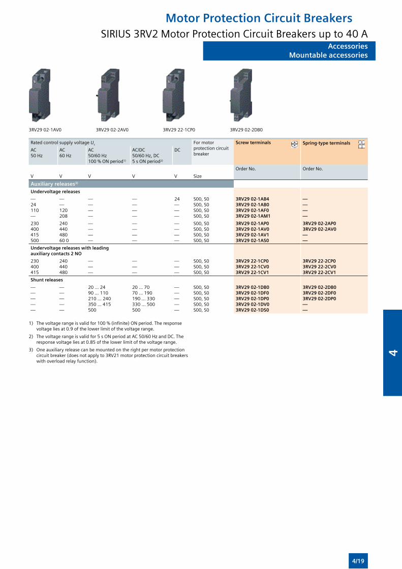
AccessoriesMountable accessories
AccessoriesMountable accessories
3RV29 02-1AV0 3RV29 02-2AV0 3RV29 22-1CP0 3RV29 02-2DB0
Rated control supply voltage Us For motor protection circuit breaker
Screw terminals Spring-type terminals
AC50 Hz
AC60 Hz
AC50/60 Hz 100 % ON period1)
AC/DC50/60 Hz, DC 5 s ON period2)
DC
Order No. Order No.
V V V V V Size
Auxiliary releases3)
Undervoltage releases
—24110—
——120208
— — — —
— — — —
24———
S00, S0S00, S0S00, S0S00, S0
3RV29 02-1AB43RV29 02-1AB03RV29 02-1AF03RV29 02-1AM1
————
230400415500
24044048060 0
— — — —
— — ——
————
S00, S0S00, S0S00, S0S00, S0
3RV29 02-1AP03RV29 02-1AV03RV29 02-1AV13RV29 02-1AS0
3RV29 02-2AP03RV29 02-2AV0——
Undervoltage releases with leading auxiliary contacts 2 NO
230400415
240440480
— — —
— — —
———
S00, S0S00, S0S00, S0
3RV29 22-1CP03RV29 22-1CV03RV29 22-1CV1
3RV29 22-2CP03RV29 22-2CV03RV29 22-2CV1
Shunt releases
—————
—————
20 ... 2490 ... 110210 ... 240350 ... 415500
20 ... 7070 ... 190190 ... 330330 ... 500500
—————
S00, S0S00, S0S00, S0S00, S0S00, S0
3RV29 02-1DB03RV29 02-1DF03RV29 02-1DP03RV29 02-1DV03RV29 02-1DS0
3RV29 02-2DB03RV29 02-2DF03RV29 02-2DP0——
1) The voltage range is valid for 100 % (infinite) ON period. The response voltage lies at 0.9 of the lower limit of the voltage range.
2) The voltage range is valid for 5 s ON period at AC 50/60 Hz and DC. The response voltage lies at 0.85 of the lower limit of the voltage range.
3) One auxiliary release can be mounted on the right per motor protection circuit breaker (does not apply to 3RV21 motor protection circuit breakers with overload relay function).
Motor Protection Circuit BreakersSIRIUS 3RV2 Motor Protection Circuit Breakers up to 40 A
4/19
4
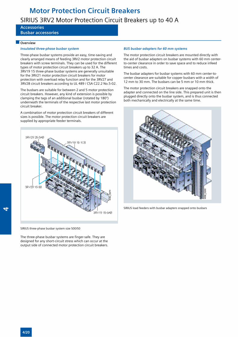
AccessoriesBusbar accessories
AccessoriesBusbar accessories
Overview
Insulated three-phase busbar system
Three-phase busbar systems provide an easy, time-saving and clearly arranged means of feeding 3RV2 motor protection circuit breakers with screw terminals. They can be used for the different types of motor protection circuit breakers up to 32 A. The 3RV19 15 three-phase busbar systems are generally unsuitable for the 3RV21 motor protection circuit breakers for motor protection with overload relay function and for the 3RV27 and 3RV28 circuit breakers according to UL 489 / CSA C22.2 No.5-02.
The busbars are suitable for between 2 and 5 motor protection circuit breakers. However, any kind of extension is possible by clamping the tags of an additional busbar (rotated by 180°) underneath the terminals of the respective last motor protection circuit breaker.
A combination of motor protection circuit breakers of different sizes is possible. The motor protection circuit breakers are supplied by appropriate feeder terminals.
SIRIUS three-phase busbar system size S00/S0
The three-phase busbar systems are finger-safe. They are designed for any short-circuit stress which can occur at the output side of connected motor protection circuit breakers.
8US busbar adapters for 60 mm systems
The motor protection circuit breakers are mounted directly with the aid of busbar adapters on busbar systems with 60 mm center-to-center clearance in order to save space and to reduce infeed times and costs.
The busbar adapters for busbar systems with 60 mm center-to-center clearance are suitable for copper busbars with a width of 12 mm to 30 mm. The busbars can be 5 mm or 10 mm thick.
The motor protection circuit breakers are snapped onto the adapter and connected on the line side. This prepared unit is then plugged directly onto the busbar system, and is thus connected both mechanically and electrically at the same time.
SIRIUS load feeders with busbar adapters snapped onto busbars
Motor Protection Circuit BreakersSIRIUS 3RV2 Motor Protection Circuit Breakers up to 40 A
4/20
4
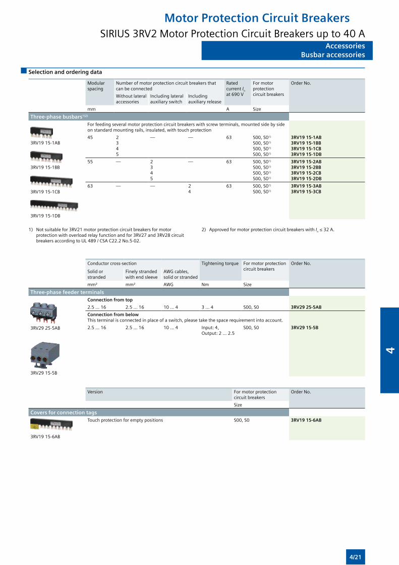
AccessoriesBusbar accessories
AccessoriesBusbar accessories
Selection and ordering data
Modular spacing
Number of motor protection circuit breakers that can be connected
Rated current In at 690 V
For motor protection circuit breakers
Order No.
Without lateral accessories
Including lateral auxiliary switch
Including auxiliary release
mm A Size
Three-phase busbars1)2)
3RV19 15-1AB
3RV19 15-1BB
3RV19 15-1CB
3RV19 15-1DB
For feeding several motor protection circuit breakers with screw terminals, mounted side by side on standard mounting rails, insulated, with touch protection
45 2345
— — 63 S00, S01)
S00, S01)
S00, S01)
S00, S01)
3RV19 15-1AB3RV19 15-1BB3RV19 15-1CB3RV19 15-1DB
55 — 2345
— 63 S00, S01)
S00, S01)
S00, S01)
S00, S01)
3RV19 15-2AB3RV19 15-2BB3RV19 15-2CB3RV19 15-2DB
63 — — 24
63 S00, S01)
S00, S01)
3RV19 15-3AB3RV19 15-3CB
1) Not suitable for 3RV21 motor protection circuit breakers for motor protection with overload relay function and for 3RV27 and 3RV28 circuit breakers according to UL 489 / CSA C22.2 No.5-02.
2) Approved for motor protection circuit breakers with In ≤ 32 A.
Conductor cross-section Tightening torque For motor protection circuit breakers
Order No.
Solid or stranded
Finely stranded with end sleeve
AWG cables, solid or stranded
mm² mm² AWG Nm Size
Three-phase feeder terminals
3RV29 25-5AB
3RV29 15-5B
Connection from top
2.5 ... 16 2.5 ... 16 10 ... 4 3 ... 4 S00, S0 3RV29 25-5AB
Connection from belowThis terminal is connected in place of a switch, please take the space requirement into account.
2.5 ... 16 2.5 ... 16 10 ... 4 Input: 4, Output: 2 ... 2.5
S00, S0 3RV29 15-5B
Version For motor protection circuit breakers
Order No.
Size
Covers for connection tags
3RV19 15-6AB
Touch protection for empty positions S00, S0 3RV19 15-6AB
Motor Protection Circuit BreakersSIRIUS 3RV2 Motor Protection Circuit Breakers up to 40 A
4/21
4
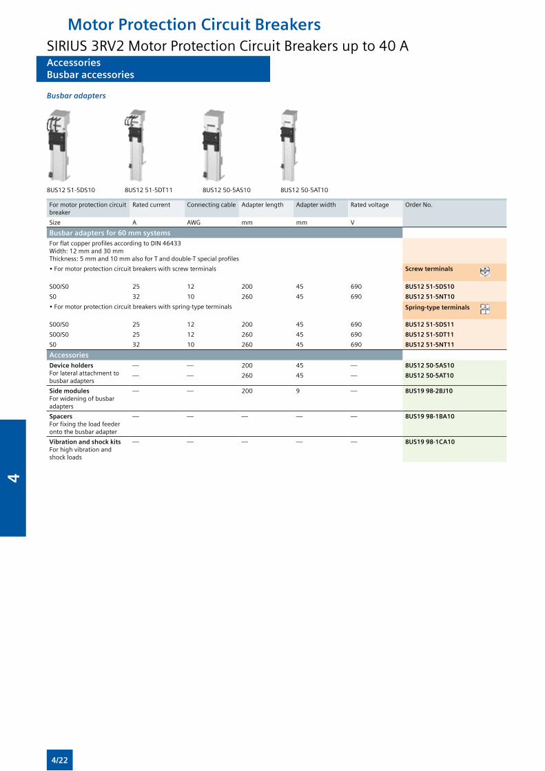
AccessoriesBusbar accessories
AccessoriesBusbar accessories
Busbar adapters
8US12 51-5DS10 8US12 51-5DT11 8US12 50-5AS10 8US12 50-5AT10
For motor protection circuit breaker
Rated current Connecting cable Adapter length Adapter width Rated voltage Order No.
Size A AWG mm mm V
Busbar adapters for 60 mm systemsFor flat copper profiles according to DIN 46433 Width: 12 mm and 30 mm Thickness: 5 mm and 10 mm also for T and double-T special profiles
• For motor protection circuit breakers with screw terminals Screw terminals
S00/S0 25 12 200 45 690 8US12 51-5DS10
S0 32 10 260 45 690 8US12 51-5NT10
• For motor protection circuit breakers with spring-type terminals Spring-type terminals
S00/S0 25 12 200 45 690 8US12 51-5DS11
S00/S0 25 12 260 45 690 8US12 51-5DT11
S0 32 10 260 45 690 8US12 51-5NT11
AccessoriesDevice holders For lateral attachment to busbar adapters
— — 200 45 — 8US12 50-5AS10
— — 260 45 — 8US12 50-5AT10
Side modules For widening of busbar adapters
— — 200 9 — 8US19 98-2BJ10
Spacers For fixing the load feeder onto the busbar adapter
— — — — — 8US19 98-1BA10
Vibration and shock kits For high vibration and shock loads
— — — — — 8US19 98-1CA10
Motor Protection Circuit BreakersSIRIUS 3RV2 Motor Protection Circuit Breakers up to 40 A
4/22
4
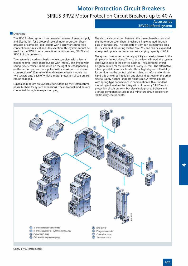
Accessories3RV29 infeed system
Accessories3RV29 infeed system
Overview
The 3RV29 infeed system is a convenient means of energy supply and distribution for a group of several motor protection circuit breakers or complete load feeders with a screw or spring-type connection in sizes S00 and S0 (exception: this system cannot be used for the 3RV21motor protection circuit breakers, 3RV27 and 3RV28 circuit breakers).
The system is based on a basic module complete with a lateral incoming unit (three-phase busbar with infeed). This infeed with spring-type terminals is mounted on the right or left depending on the version and can be supplied with a maximum conductor cross-section of 25 mm2 (with end sleeve). A basic module has two sockets onto each of which a motor protection circuit breaker can be snapped.
Expansion modules are available for extending the system (three-phase busbars for system expansion). The individual modules are connected through an expansion plug.
The electrical connection between the three-phase busbars and the motor protection circuit breakers is implemented through plug-in connectors. The complete system can be mounted on a TH 35 standard mounting rail to EN 60715 and can be expanded as required up to a maximum current carrying capacity of 63 A.
The system is mounted extremely quickly and easily thanks to the simple plug-in technique. Thanks to the lateral infeed, the system also saves space in the control cabinet. The additional overall height required for the infeed unit is only 30 mm. The alternative infeed possibilities on each side offer a high degree of flexibility for configuring the control cabinet: Infeed on left-hand or right-hand side as well as infeed on one side and outfeed on the other side to supply further loads are all possible. A terminal block with spring-type connections in combination with a standard mounting rail enables the integration of not only SIRIUS motor protection circuit breakers but also single-phase, 2-phase and 3-phase components such as 5SY miniature circuit breakers or SIRIUS relay components.
SIRIUS 3RV29 infeed system
Motor Protection Circuit BreakersSIRIUS 3RV2 Motor Protection Circuit Breakers up to 40 A
4/23
4
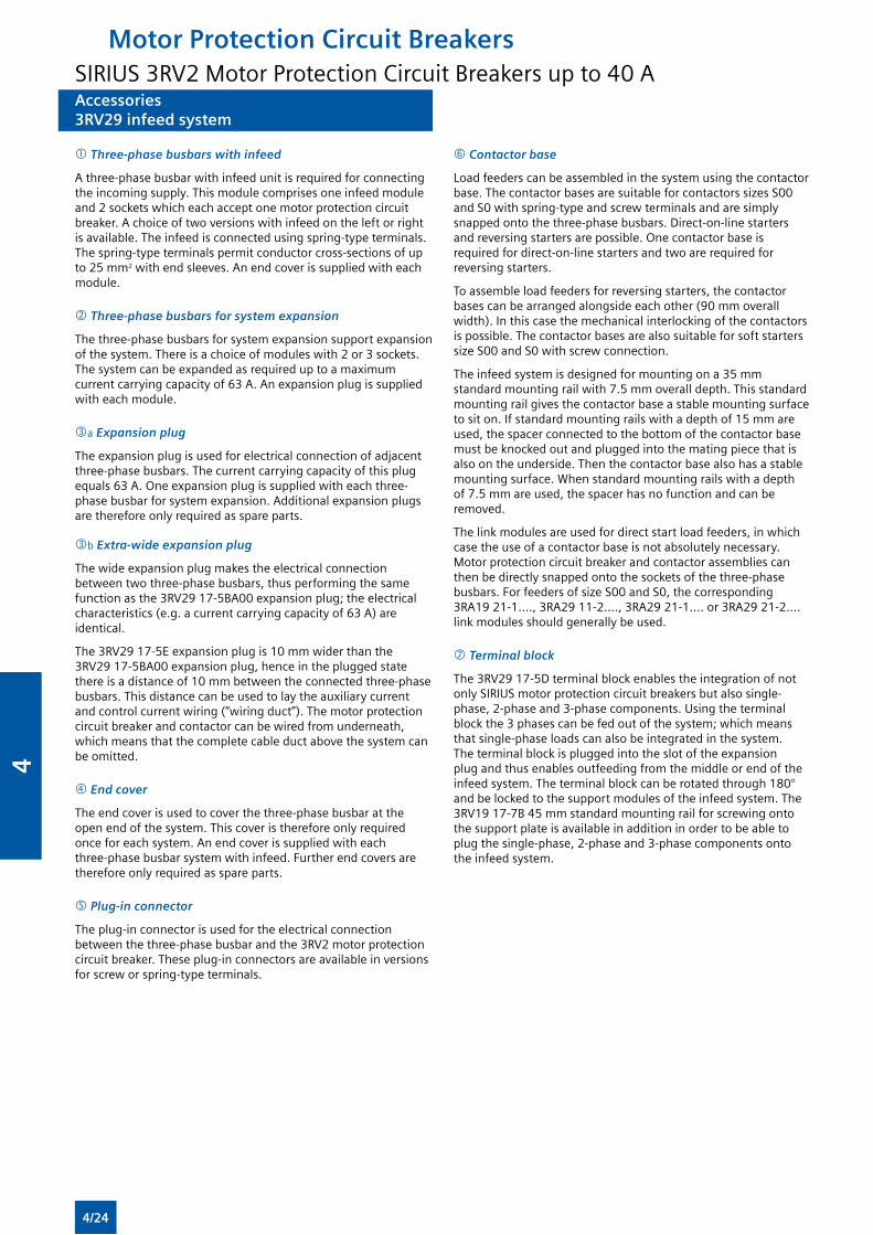
Accessories3RV29 infeed system
Accessories3RV29 infeed system
Three-phase busbars with infeed
A three-phase busbar with infeed unit is required for connecting the incoming supply. This module comprises one infeed module and 2 sockets which each accept one motor protection circuit breaker. A choice of two versions with infeed on the left or right is available. The infeed is connected using spring-type terminals. The spring-type terminals permit conductor cross-sections of up to 25 mm2 with end sleeves. An end cover is supplied with each module.
Three-phase busbars for system expansion
The three-phase busbars for system expansion support expansion of the system. There is a choice of modules with 2 or 3 sockets. The system can be expanded as required up to a maximum current carrying capacity of 63 A. An expansion plug is supplied with each module.
a Expansion plug
The expansion plug is used for electrical connection of adjacent three-phase busbars. The current carrying capacity of this plug equals 63 A. One expansion plug is supplied with each three-phase busbar for system expansion. Additional expansion plugs are therefore only required as spare parts.
b Extra-wide expansion plug
The wide expansion plug makes the electrical connection between two three-phase busbars, thus performing the same function as the 3RV29 17-5BA00 expansion plug; the electrical characteristics (e.g. a current carrying capacity of 63 A) are identical.
The 3RV29 17-5E expansion plug is 10 mm wider than the 3RV29 17-5BA00 expansion plug, hence in the plugged state there is a distance of 10 mm between the connected three-phase busbars. This distance can be used to lay the auxiliary current and control current wiring (“wiring duct”). The motor protection circuit breaker and contactor can be wired from underneath, which means that the complete cable duct above the system can be omitted.
End cover
The end cover is used to cover the three-phase busbar at the open end of the system. This cover is therefore only required once for each system. An end cover is supplied with each three-phase busbar system with infeed. Further end covers are therefore only required as spare parts.
Plug-in connector
The plug-in connector is used for the electrical connection between the three-phase busbar and the 3RV2 motor protection circuit breaker. These plug-in connectors are available in versions for screw or spring-type terminals.
Contactor base
Load feeders can be assembled in the system using the contactor base. The contactor bases are suitable for contactors sizes S00 and S0 with spring-type and screw terminals and are simply snapped onto the three-phase busbars. Direct-on-line starters and reversing starters are possible. One contactor base is required for direct-on-line starters and two are required for reversing starters.
To assemble load feeders for reversing starters, the contactor bases can be arranged alongside each other (90 mm overall width). In this case the mechanical interlocking of the contactors is possible. The contactor bases are also suitable for soft starters size S00 and S0 with screw connection.
The infeed system is designed for mounting on a 35 mm standard mounting rail with 7.5 mm overall depth. This standard mounting rail gives the contactor base a stable mounting surface to sit on. If standard mounting rails with a depth of 15 mm are used, the spacer connected to the bottom of the contactor base must be knocked out and plugged into the mating piece that is also on the underside. Then the contactor base also has a stable mounting surface. When standard mounting rails with a depth of 7.5 mm are used, the spacer has no function and can be removed.
The link modules are used for direct start load feeders, in which case the use of a contactor base is not absolutely necessary. Motor protection circuit breaker and contactor assemblies can then be directly snapped onto the sockets of the three-phase busbars. For feeders of size S00 and S0, the corresponding 3RA19 21-1...., 3RA29 11-2...., 3RA29 21-1.... or 3RA29 21-2.... link modules should generally be used.
Terminal block
The 3RV29 17-5D terminal block enables the integration of not only SIRIUS motor protection circuit breakers but also single-phase, 2-phase and 3-phase components. Using the terminal block the 3 phases can be fed out of the system; which means that single-phase loads can also be integrated in the system. The terminal block is plugged into the slot of the expansion plug and thus enables outfeeding from the middle or end of the infeed system. The terminal block can be rotated through 180° and be locked to the support modules of the infeed system. The 3RV19 17-7B 45 mm standard mounting rail for screwing onto the support plate is available in addition in order to be able to plug the single-phase, 2-phase and 3-phase components onto the infeed system.
Motor Protection Circuit BreakersSIRIUS 3RV2 Motor Protection Circuit Breakers up to 40 A
4/24
4
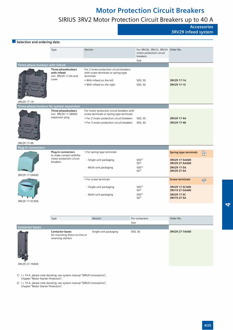
Accessories3RV29 infeed system
Accessories3RV29 infeed system
Selection and ordering data
Type
Version
For 3RV20, 3RV23, 3RV24 motor protection circuit breakers
Order No.
Size
Three-phase busbars with infeed
3RV29 17-1A
Three-phasebusbars with infeedincl. 3RV29 17-6A end cover
For 2 motor protection circuit breakers with screw terminals or spring-type terminals
• With infeed on the left S00, S0 3RV29 17-1A
• With infeed on the right S00, S0 3RV29 17-1E
Three-phase busbars for system expansion
3RV29 17-4A
Three-phasebusbarsincl. 3RV29 17-5BA00 expansion plug
For motor protection circuit breakers with screw terminals or spring-type terminals
• For 2 motor protection circuit breakers S00, S0 3RV29 17-4A
• For 3 motor protection circuit breakers S00, S0 3RV29 17-4B
Plug-in connectors
3RV29 17-5AA00
Plug-in connectorsto make contact withthe motor protection circuit breakers
• For spring-type terminals Spring-type terminals
- Single-unit packaging S001)
S02)3RV29 17-5AA003RV29 27-5AA00
- Multi-unit packaging S001)
S02)3RV29 17-5A3RV29 27-5A
3RV29 17-5CA00
• For screw terminals Screw terminals
- Single-unit packaging S001)
S02)3RV29 17-5CA003RV19 27-5AA00
- Multi-unit packaging S001)
S02)3RV29 17-5C3RV19 27-5A
Type Version For contactors Order No. Size
Contactor bases
3RV29 27-7AA00
Contactor basesfor mounting direct-on-line or reversing starters
Single-unit packaging S00, S0 3RV29 27-7AA00
1) I > 14 A, please note derating; see system manual “SIRIUS Innovations”, Chapter “Motor Starter Protectors”.
2) I > 16 A, please note derating; see system manual “SIRIUS Innovations”, Chapter “Motor Starter Protectors”.
Motor Protection Circuit BreakersSIRIUS 3RV2 Motor Protection Circuit Breakers up to 40 A
4/25
4
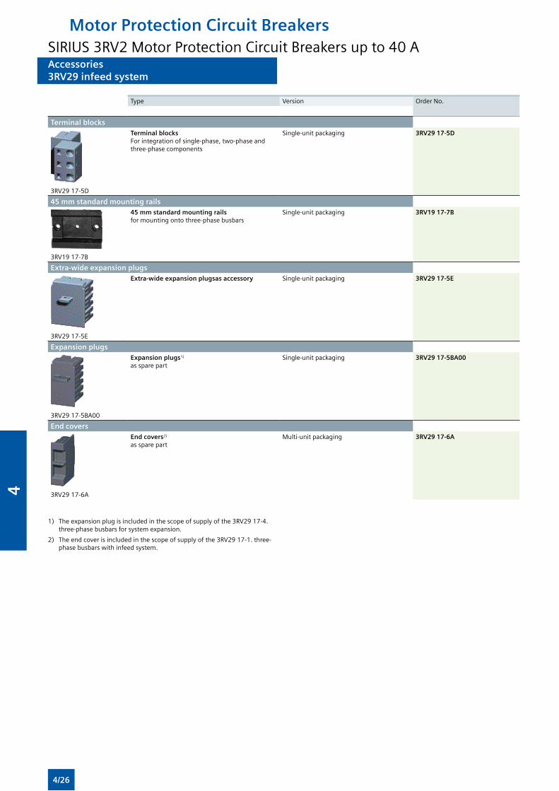
Accessories3RV29 infeed system
Accessories3RV29 infeed system
Type Version Order No.
Terminal blocks
3RV29 17-5D
Terminal blocks For integration of single-phase, two-phase and three-phase components
Single-unit packaging 3RV29 17-5D
45 mm standard mounting rails
3RV19 17-7B
45 mm standard mounting rails for mounting onto three-phase busbars
Single-unit packaging 3RV19 17-7B
Extra-wide expansion plugs
3RV29 17-5E
Extra-wide expansion plugsas accessory Single-unit packaging 3RV29 17-5E
Expansion plugs
3RV29 17-5BA00
Expansion plugs1)
as spare partSingle-unit packaging 3RV29 17-5BA00
End covers
3RV29 17-6A
End covers2)
as spare partMulti-unit packaging 3RV29 17-6A
1) The expansion plug is included in the scope of supply of the 3RV29 17-4. three-phase busbars for system expansion.
2) The end cover is included in the scope of supply of the 3RV29 17-1. three-phase busbars with infeed system.
Motor Protection Circuit BreakersSIRIUS 3RV2 Motor Protection Circuit Breakers up to 40 A
4/26
4
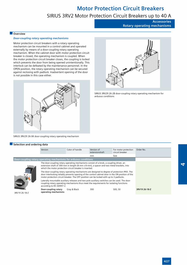
AccessoriesRotary operating mechanisms
AccessoriesRotary operating mechanisms
Overview
Door-coupling rotary operating mechanisms
Motor protection circuit breakers with a rotary operating mechanism can be mounted in a control cabinet and operated externally by means of a door-coupling rotary operating mechanism. When the cabinet door with motor protection circuit breaker is closed, the operating mechanism is coupled. When the motor protection circuit breaker closes, the coupling is locked which prevents the door from being opened unintentionally. This interlock can be defeated by the maintenance personnel. In the OPEN position, the rotary operating mechanism can be secured against reclosing with padlock. Inadvertent opening of the door is not possible in this case either.
SIRIUS 3RV29 26-0K door-coupling rotary operating mechanism
SIRIUS 3RV29 26-2B door-coupling rotary operating mechanism for arduous conditions
Selection and ordering data
Version Color of handle Version of extensionshaft
For motor protection circuit breaker
Order No.
mm Size
Door-coupling rotary operating mechanisms for arduous conditions
3RV19 26-1B-Z
The door-coupling rotary operating mechanisms consist of a knob, a coupling driver, an extension shaft of 300 mm in length (8 mm x 8 mm), a spacer and two metal brackets, into which the motor protection circuit breaker is inserted.
The door-coupling rotary operating mechanisms are designed to degree of protection IP65. The door interlocking reliably prevents opening of the control cabinet door in the ON position of the motor protection circuit breaker. The OFF position can be locked with up to 3 padlocks.
Laterally mountable auxiliary releases and two-pole auxiliary switches can be used. The door-coupling rotary operating mechanisms thus meet the requirements for isolating functions according to IEC 60947-2.
Door-coupling rotary operating mechanisms
Gray & Black 300 S00, S0 3RV19 26-1B-Z
Motor Protection Circuit BreakersSIRIUS 3RV2 Motor Protection Circuit Breakers up to 40 A
4/27
4
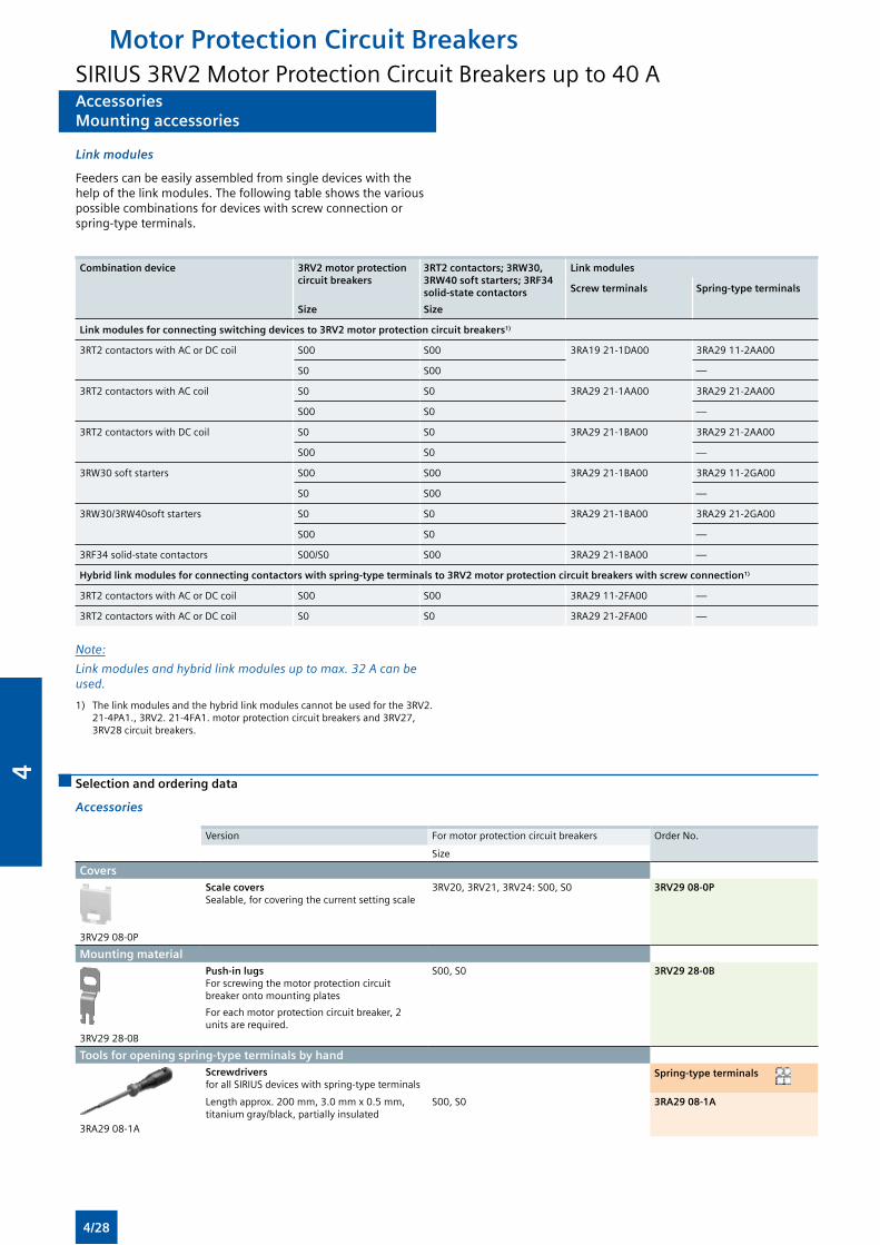
AccessoriesMounting accessories
AccessoriesMounting accessories
Link modules
Feeders can be easily assembled from single devices with the help of the link modules. The following table shows the various possible combinations for devices with screw connection or spring-type terminals.
Combination device 3RV2 motor protection circuit breakers
Size
3RT2 contactors; 3RW30, 3RW40 soft starters; 3RF34 solid-state contactors
Size
Link modules
Screw terminals Spring-type terminals
Link modules for connecting switching devices to 3RV2 motor protection circuit breakers1)
3RT2 contactors with AC or DC coil S00 S00 3RA19 21-1DA00 3RA29 11-2AA00
S0 S00 —
3RT2 contactors with AC coil S0 S0 3RA29 21-1AA00 3RA29 21-2AA00
S00 S0 —
3RT2 contactors with DC coil S0 S0 3RA29 21-1BA00 3RA29 21-2AA00
S00 S0 —
3RW30 soft starters S00 S00 3RA29 21-1BA00 3RA29 11-2GA00
S0 S00 —
3RW30/3RW40soft starters S0 S0 3RA29 21-1BA00 3RA29 21-2GA00
S00 S0 —
3RF34 solid-state contactors S00/S0 S00 3RA29 21-1BA00 —
Hybrid link modules for connecting contactors with spring-type terminals to 3RV2 motor protection circuit breakers with screw connection1)
3RT2 contactors with AC or DC coil S00 S00 3RA29 11-2FA00 —
3RT2 contactors with AC or DC coil S0 S0 3RA29 21-2FA00 —
Note:
Linkmodulesandhybridlinkmodulesuptomax.32Acanbeused.
1) The link modules and the hybrid link modules cannot be used for the 3RV2. 21-4PA1., 3RV2. 21-4FA1. motor protection circuit breakers and 3RV27, 3RV28 circuit breakers.
Selection and ordering data
Accessories
Version For motor protection circuit breakers Order No.
Size
Covers
3RV29 08-0P
Scale covers Sealable, for covering the current setting scale
3RV20, 3RV21, 3RV24: S00, S0 3RV29 08-0P
Mounting material
3RV29 28-0B
Push-in lugs For screwing the motor protection circuit breaker onto mounting plates
For each motor protection circuit breaker, 2 units are required.
S00, S0 3RV29 28-0B
Tools for opening spring-type terminals by hand
3RA29 08-1A
Screwdrivers for all SIRIUS devices with spring-type terminals
Spring-type terminals
Length approx. 200 mm, 3.0 mm x 0.5 mm, titanium gray/black, partially insulated
S00, S0 3RA29 08-1A
Motor Protection Circuit BreakersSIRIUS 3RV2 Motor Protection Circuit Breakers up to 40 A
4/28
4
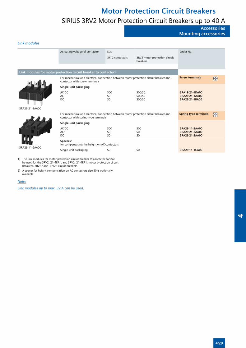
AccessoriesMounting accessories
AccessoriesMounting accessories
Link modules
Actuating voltage of contactor Size Order No.
3RT2 contactors 3RV2 motor protection circuit breakers
Link modules for motor protection circuit breaker to contactor1)
3RA29 21-1AA00
For mechanical and electrical connection between motor protection circuit breaker and contactor with screw terminals
Screw terminals
Single-unit packaging
AC/DCACDC
S00S0S0
S00/S0S00/S0S00/S0
3RA19 21-1DA003RA29 21-1AA003RA29 21-1BA00
3RA29 11-2AA00
For mechanical and electrical connection between motor protection circuit breaker and contactor with spring-type terminals
Spring-type terminals
Single-unit packaging
AC/DCAC2)
DC
S00S0S0
S00S0S0
3RA29 11-2AA003RA29 21-2AA003RA29 21-2AA00
Spacers2)
for compensating the height on AC contactors
Single-unit packaging S0 S0 3RA29 11-1CA00
1) The link modules for motor protection circuit breaker to contactor cannot be used for the 3RV2. 21-4PA1. and 3RV2. 21-4FA1. motor protection circuit breakers, 3RV27 and 3RV28 circuit breakers.
2) A spacer for height compensation on AC contactors size S0 is optionally available.
Note:
Linkmodulesuptomax.32Acanbeused.
Motor Protection Circuit BreakersSIRIUS 3RV2 Motor Protection Circuit Breakers up to 40 A
4/29
4
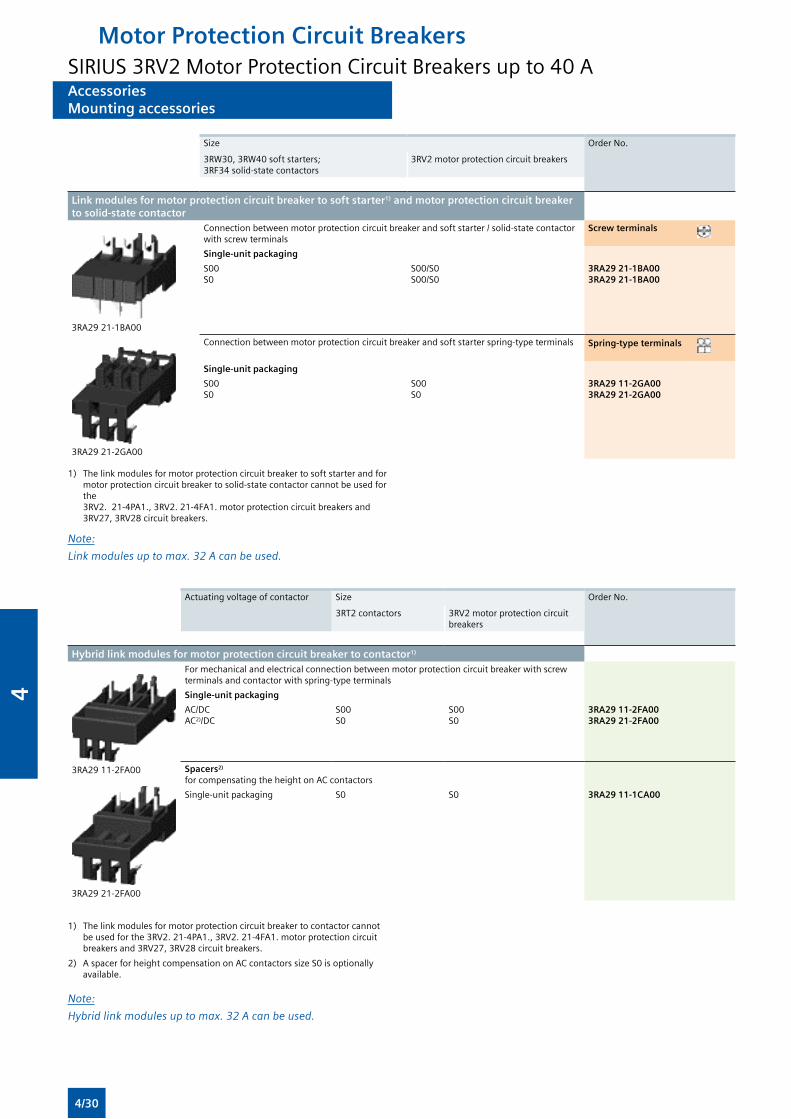
AccessoriesMounting accessories
AccessoriesMounting accessories
Size Order No.
3RW30, 3RW40 soft starters; 3RF34 solid-state contactors
3RV2 motor protection circuit breakers
Link modules for motor protection circuit breaker to soft starter1) and motor protection circuit breaker to solid-state contactor
3RA29 21-1BA00
Connection between motor protection circuit breaker and soft starter / solid-state contactor with screw terminals
Screw terminals
Single-unit packaging
S00S0
S00/S0S00/S0
3RA29 21-1BA003RA29 21-1BA00
3RA29 21-2GA00
Connection between motor protection circuit breaker and soft starter spring-type terminals Spring-type terminals
Single-unit packaging
S00S0
S00S0
3RA29 11-2GA003RA29 21-2GA00
1) The link modules for motor protection circuit breaker to soft starter and for motor protection circuit breaker to solid-state contactor cannot be used for the 3RV2. 21-4PA1., 3RV2. 21-4FA1. motor protection circuit breakers and 3RV27, 3RV28 circuit breakers.
Note:
Linkmodulesuptomax.32Acanbeused.
Actuating voltage of contactor Size Order No.
3RT2 contactors 3RV2 motor protection circuit breakers
Hybrid link modules for motor protection circuit breaker to contactor1)
3RA29 11-2FA00
3RA29 21-2FA00
For mechanical and electrical connection between motor protection circuit breaker with screw terminals and contactor with spring-type terminals
Single-unit packaging
AC/DCAC2)/DC
S00S0
S00S0
3RA29 11-2FA003RA29 21-2FA00
Spacers2)
for compensating the height on AC contactors
Single-unit packaging S0 S0 3RA29 11-1CA00
1) The link modules for motor protection circuit breaker to contactor cannot be used for the 3RV2. 21-4PA1., 3RV2. 21-4FA1. motor protection circuit breakers and 3RV27, 3RV28 circuit breakers.
2) A spacer for height compensation on AC contactors size S0 is optionally available.
Note:
Hybridlinkmodulesuptomax.32Acanbeused.
Motor Protection Circuit BreakersSIRIUS 3RV2 Motor Protection Circuit Breakers up to 40 A
4/30
4
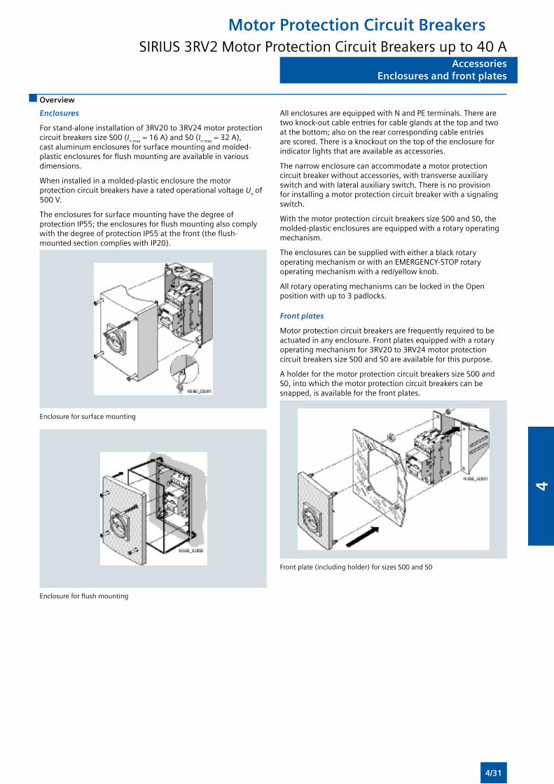
AccessoriesEnclosures and front plates
AccessoriesEnclosures and front plates
Overview
Enclosures
For stand-alone installation of 3RV20 to 3RV24 motor protection circuit breakers size S00 (In max = 16 A) and S0 (In max = 32 A), cast aluminum enclosures for surface mounting and molded-plastic enclosures for flush mounting are available in various dimensions.
When installed in a molded-plastic enclosure the motor protection circuit breakers have a rated operational voltage Ue of 500 V.
The enclosures for surface mounting have the degree of protection IP55; the enclosures for flush mounting also comply with the degree of protection IP55 at the front (the flush-mounted section complies with IP20).
All enclosures are equipped with N and PE terminals. There are two knock-out cable entries for cable glands at the top and two at the bottom; also on the rear corresponding cable entries are scored. There is a knockout on the top of the enclosure for indicator lights that are available as accessories.
The narrow enclosure can accommodate a motor protection circuit breaker without accessories, with transverse auxiliary switch and with lateral auxiliary switch. There is no provision for installing a motor protection circuit breaker with a signaling switch.
With the motor protection circuit breakers size S00 and S0, the molded-plastic enclosures are equipped with a rotary operating mechanism.
The enclosures can be supplied with either a black rotary operating mechanism or with an EMERGENCY-STOP rotary operating mechanism with a red/yellow knob.
All rotary operating mechanisms can be locked in the Open position with up to 3 padlocks.
Front plates
Motor protection circuit breakers are frequently required to be actuated in any enclosure. Front plates equipped with a rotary operating mechanism for 3RV20 to 3RV24 motor protection circuit breakers size S00 and S0 are available for this purpose.
A holder for the motor protection circuit breakers size S00 and S0, into which the motor protection circuit breakers can be snapped, is available for the front plates.
Enclosure for surface mounting
Enclosure for flush mounting
Front plate (including holder) for sizes S00 and S0
Motor Protection Circuit BreakersSIRIUS 3RV2 Motor Protection Circuit Breakers up to 40 A
4/31
4
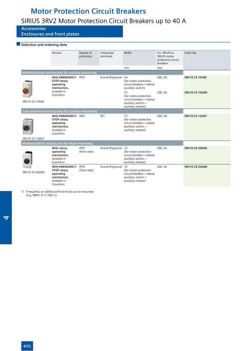
AccessoriesEnclosures and front plates
AccessoriesEnclosures and front plates
Selection and ordering data
Version Degree of protection
Integrated terminals
Width For 3RV20 to 3RV24 motor protection circuit breakers
Order No.
mm Size
Molded-plastic enclosures for surface mounting
3RV19 23-1FA00
With EMERGENCY-STOP rotary operating mechanism, lockable in 0 position
IP55 N and PE/ground 54 (for motor protection circuit breakers + lateral auxiliary switch)
S00, S0 3RV19 23-1FA00
72 (for motor protection circuit breakers + lateral auxiliary switch + auxiliary release)
S00, S0 3RV19 23-1GA00
Cast aluminum enclosures for surface mounting
3RV19 23-1DA01
With EMERGENCY-STOP rotary operating mechanism, lockable in 0 position
IP65 PE1) 72 (for motor protection circuit breakers + lateral auxiliary switch + auxiliary release)
S00, S0 3RV19 23-1GA01
Molded-plastic enclosures for flush mounting
3RV19 23-2DA00
With rotary operating mechanism, lockable in 0 position
IP55 (front side)
N and PE/ground 72 (for motor protection circuit breakers + lateral auxiliary switch + auxiliary release)
S00, S0 3RV19 23-2DA00
With EMERGENCY-STOP rotary operating mechanism, lockable in 0 position
IP55 (front side)
N and PE/ground 72 (for motor protection circuit breakers + lateral auxiliary switch + auxiliary release)
S00, S0 3RV19 23-2GA00
1) If required, an additional N terminal can be mounted (e.g. 8WA1 011-1BG11).
Motor Protection Circuit BreakersSIRIUS 3RV2 Motor Protection Circuit Breakers up to 40 A
4/32
4
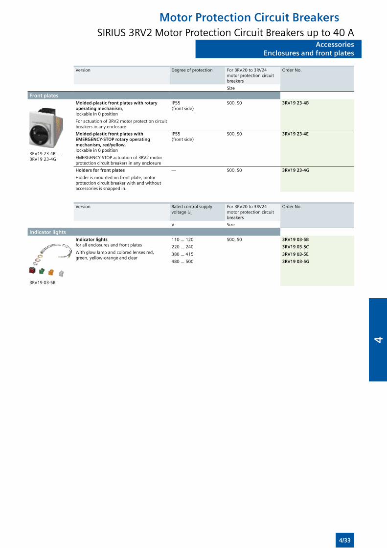
AccessoriesEnclosures and front plates
AccessoriesEnclosures and front plates
Version Degree of protection For 3RV20 to 3RV24 motor protection circuit breakers
Order No.
Size
Front plates
3RV19 23-4B + 3RV19 23-4G
Molded-plastic front plates with rotary operating mechanism, lockable in 0 position
For actuation of 3RV2 motor protection circuit breakers in any enclosure
IP55 (front side)
S00, S0 3RV19 23-4B
Molded-plastic front plates with EMERGENCY-STOP rotary operating mechanism, red/yellow, lockable in 0 position
EMERGENCY-STOP actuation of 3RV2 motor protection circuit breakers in any enclosure
IP55 (front side)
S00, S0 3RV19 23-4E
Holders for front plates
Holder is mounted on front plate, motor protection circuit breaker with and without accessories is snapped in.
— S00, S0 3RV19 23-4G
Version Rated control supply voltage Us
For 3RV20 to 3RV24 motor protection circuit breakers
Order No.
V Size
Indicator lights
3RV19 03-5B
Indicator lights for all enclosures and front plates
With glow lamp and colored lenses red, green, yellow-orange and clear
110 ... 120
220 ... 240
380 ... 415
480 ... 500
S00, S0 3RV19 03-5B
3RV19 03-5C
3RV19 03-5E
3RV19 03-5G
Motor Protection Circuit BreakersSIRIUS 3RV2 Motor Protection Circuit Breakers up to 40 A
4/33
4
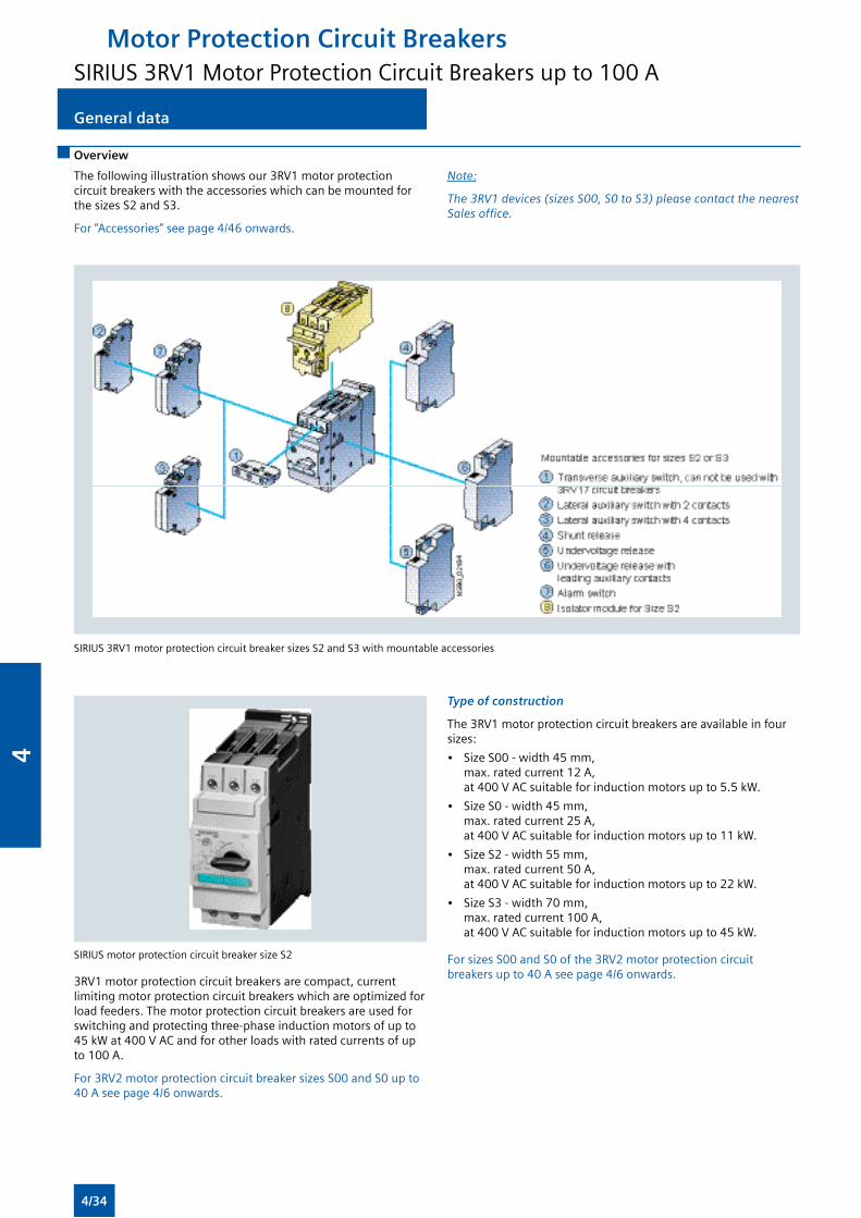
General dataGeneral data
Overview
The following illustration shows our 3RV1 motor protection circuit breakers with the accessories which can be mounted for the sizes S2 and S3.
For “Accessories” see page 4/46 onwards.
SIRIUS 3RV1 motor protection circuit breaker sizes S2 and S3 with mountable accessories
SIRIUS motor protection circuit breaker size S2
3RV1 motor protection circuit breakers are compact, current limiting motor protection circuit breakers which are optimized for load feeders. The motor protection circuit breakers are used for switching and protecting three-phase induction motors of up to 45 kW at 400 V AC and for other loads with rated currents of up to 100 A.
For 3RV2 motor protection circuit breaker sizes S00 and S0 up to 40 A see page 4/6 onwards.
Type of construction
The 3RV1 motor protection circuit breakers are available in four sizes:
• Size S00 - width 45 mm, max. rated current 12 A, at 400 V AC suitable for induction motors up to 5.5 kW.
• Size S0 - width 45 mm, max. rated current 25 A, at 400 V AC suitable for induction motors up to 11 kW.
• Size S2 - width 55 mm, max. rated current 50 A, at 400 V AC suitable for induction motors up to 22 kW.
• Size S3 - width 70 mm, max. rated current 100 A, at 400 V AC suitable for induction motors up to 45 kW.
For sizes S00 and S0 of the 3RV2 motor protection circuit breakers up to 40 A see page 4/6 onwards.
Note:
The3RV1devices(sizesS00,S0toS3)pleasecontactthenearestSalesoffice.
Motor Protection Circuit BreakersSIRIUS 3RV1 Motor Protection Circuit Breakers up to 100 A
4/34
4
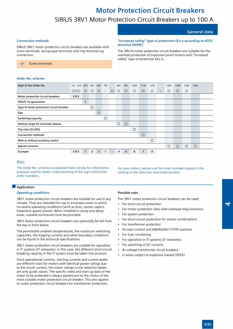
General data
Connection methods
SIRIUS 3RV1 motor protection circuit breakers are available with screw terminals, spring-type terminals and ring terminal lug connection.
Screw terminals
“Increased safety” type of protection EEx e according to ATEX directive 94/9/EC
The 3RV10 motor protection circuit breakers are suitable for the overload protection of explosion-proof motors with “increased safety” type of protection EEx e;
Order No. scheme
Digit of the Order No. 1st - 3rd 4th 5th 6th 7th 8th 9th 10th 11th 12th 13th 14th 15th 16th
– –
Motor protection circuit breakers 3 R V
SIRIUS 1st generation 1
Type of motor protection circuit breaker
Size
Switching capacity
Setting range for overload release
Trip class (CLASS)
Connection methods
With or without auxiliary switch
Special versions
Example 3 R V 1 0 3 1 – 4 A A 1 0
Note:
The Order No. scheme is presented here merely for information purposes and for better understanding of the logic behind the order numbers.
For your orders, please use the order numbers quote in the catalog in the Selection and ordering data.
Application
Operating conditions
3RV1 motor protection circuit breakers are suitable for use in any climate. They are intended for use in enclosed rooms in which no severe operating conditions (such as dust, caustic vapors, hazardous gases) prevail. When installed in dusty and damp areas, suitable enclosures must be provided.
3RV1 motor protection circuit breakers can optionally be fed from the top or from below.
The permissible ambient temperatures, the maximum switching capacities, the tripping currents and other boundary conditions can be found in the technical specifications.
3RV1 motor protection circuit breakers are suitable for operation in IT systems (IT networks). In this case, the different short-circuit breaking capacity in the IT system must be taken into account.
Since operational currents, starting currents and current peaks are different even for motors with identical power ratings due to the inrush current, the motor ratings in the selection tables are only guide values. The specific rated and start-up data of the motor to be protected is always paramount to the choice of the most suitable motor protection circuit breaker. This also applies to motor protection circuit breakers for transformer protection.
Possible uses
The 3RV1 motor protection circuit breakers can be used:
• For short-circuit protection
• For motor protection (also with overload relay function)
• For system protection
• For short-circuit protection for starter combinations
• For transformer protection
• As main control and EMERGENCY-STOP switches
• For fuse monitoring
• For operation in IT systems (IT networks)
• For switching of DC currents
• As voltage transformer circuit breakers
• In areas subject to explosion hazard (ATEX)
Motor Protection Circuit BreakersSIRIUS 3RV1 Motor Protection Circuit Breakers up to 100 A
General data
4/35
4
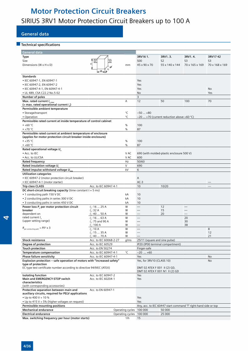
General dataGeneral data
Technical specifications
General dataType 3RV16 1. 3RV1. 3. 3RV1. 4. 3RV17 42Size S00 S2 S3 S3Dimensions (W x H x D) mm 45 x 90 x 70 55 x 140 x 144 70 x 165 x 169 70 x 168 x 169
Standards • IEC 60947-1, EN 60947-1 Yes• IEC 60947-2, EN 60947-2 Yes• IEC 60947-4-1, EN 60947-4-1 Yes No• UL 489, CSA C22.2 No.5-02 No YesNumber of poles 3Max. rated current In max (= max. rated operational current Ie)
A 12 50 100 70
Permissible ambient temperature• Storage/transport °C –50 ... +80 • Operation °C –20 ... +70 (current reduction above +60 °C)Permissible rated current at inside temperature of control cabinet • +60 °C % 100• +70 °C % 87Permissible rated current at ambient temperature of enclosure (applies for motor protection circuit breaker inside enclosure)• +35 °C % 100• +60 °C % 87Rated operational voltage Ue • Acc. to IEC V AC 690 (with molded-plastic enclosure 500 V)• Acc. to UL/CSA V AC 600Rated frequency Hz 50/60Rated insulation voltage Ui V 690Rated impulse withstand voltage Uimp kV 6Utilization categories • IEC 60947-2 (motor protection circuit breaker) A• IEC 60947-4-1 (motor starter) AC-3 —Trip class CLASS Acc. to IEC 60947-4-1 10 10/20 —DC short-circuit breaking capacity (time constant t = 5 ms) • 1 conducting path 150 V DC kA 10• 2 conducting paths in series 300 V DC kA 10• 3 conducting paths in series 450 V DC kA 10Power loss Pv per motor protection circuit breaker dependent on rated current In (upper setting range)
Rper conducting path = P/I2 x 3
In: 16 ... 25 AIn: 32 AIn: 40 ... 50 A
WWW
———
121520
———
In: 16 ... 63 AIn: 75 and 90 AIn: 100 A
WWW
———
203038
In: 10 AIn: 15 ... 35 AIn: 40 ... 70 A
WWW
———
81221
Shock resistance Acc. to IEC 60068-2-27 g/ms 25/11 (square and sine pulse)Degree of protection Acc. to IEC 60529 IP20 (IP00 terminal compartment)Touch protection Acc. to EN 50274 Finger-safeTemperature compensation Acc. to IEC 60947-4-1 °C –20 ... +60Phase failure sensitivity Acc. to IEC 60947-4-1 Yes NoExplosion protection – safe operation of motors with “increased safety” type of protectionEC type test certificate number according to directive 94/9/EC (ATEX)
Yes, for 3RV10 (CLASS 10)
DMT 02 ATEX F 001 II (2) GD, DMT 02 ATEX F 001 N1 II (2) GD
No
Isolating functionMain and EMERGENCY-STOP switch characteristics (with corresponding accessories)
Acc. to IEC 60947-2Acc. to IEC 60204-1
YesYes
Protective separation between main and auxiliary circuits, required for PELV applications
Acc. to EN 60947-1
• Up to 400 V + 10 % Yes• Up to 415 V + 5% (higher voltages on request) YesPermissible mounting positions Any, acc. to IEC 60447 start command “I” right-hand side or topMechanical endurance Operating cycles 100 000 50 000Electrical endurance Operating cycles 100 000 25 000Max. switching frequency per hour (motor starts) 1/h 15
Motor Protection Circuit BreakersSIRIUS 3RV1 Motor Protection Circuit Breakers up to 100 A
4/36
4
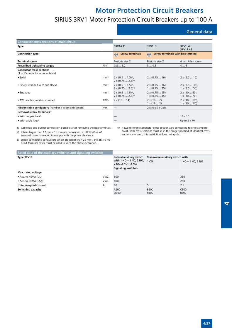
General data
Conductor cross-sections of main circuitType 3RV16 11 3RV1. 3. 3RV1. 4./
3RV17 42
Connection type Screw terminals Screw terminals with box terminal
Terminal screw Pozidriv size 2 Pozidriv size 2 4 mm Allen screw
Prescribed tightening torque Nm 0.8 ... 1.2 3 ... 4.5 4 ... 6
Conductor cross-sections (1 or 2 conductors connectable)
• Solid mm2 2 x (0.5 ... 1.5)4), 2 x (0.75 ... 2.5)4)
2 x (0.75 ... 16) 2 x (2.5 ... 16)
• Finely stranded with end sleeve mm2 2 x (0.5 ... 1.5)4), 2 x (0.75 ... 2.5)4)
2 x (0.75 ... 16), 1 x (0.75 ... 25)
2 x (2.5 ... 35), 1 x (2.5 ... 50)
• Stranded mm2 2 x (0.5 ... 1.5)4), 2 x (0.75 ... 2.5)4)
2 x (0.75 ... 25), 1 x (0.75 ... 35)
2 x (10 ... 50), 1 x (10 ... 70)
• AWG cables, solid or stranded AWG 2 x (18 ... 14) 2 x (18 ... 2), 1 x (18 ... 2)
2 x (10 ... 1/0), 1 x (10 ... 2/0)
Ribbon cable conductors (number x width x thickness) mm — 2 x (6 x 9 x 0.8)
Removable box terminals1)
• With copper bars2) — 18 x 10
• With cable lugs3) — Up to 2 x 70
1) Cable lug and busbar connection possible after removing the box terminals.
2) If bars larger than 12 mm x 10 mm are connected, a 3RT19 46-4EA1 terminal cover is needed to comply with the phase clearance.
3) When connecting conductors which are larger than 25 mm2, the 3RT19 46-4EA1 terminal cover must be used to keep the phase clearance.
4) If two different conductor cross-sections are connected to one clamping point, both cross-sections must lie in the range specified. If identical cross-sections are used, this restriction does not apply.
Rated data of the auxiliary switches and signaling switchesType 3RV19 Lateral auxiliary switch
with 1 NO + 1 NC, 2 NO, 2 NC, 2 NO + 2 NC;
Signaling switches
Transverse auxiliary switch with
1 CO 1 NO + 1 NC, 2 NO
Max. rated voltage
• Acc. to NEMA (UL) V AC 600 250
• Acc. to NEMA (CSA) V AC 600 250
Uninterrupted current A 10 5 2.5
Switching capacity A600 Q300
B600 R300
C300 R300
Motor Protection Circuit BreakersSIRIUS 3RV1 Motor Protection Circuit Breakers up to 100 A
General data
4/37
4
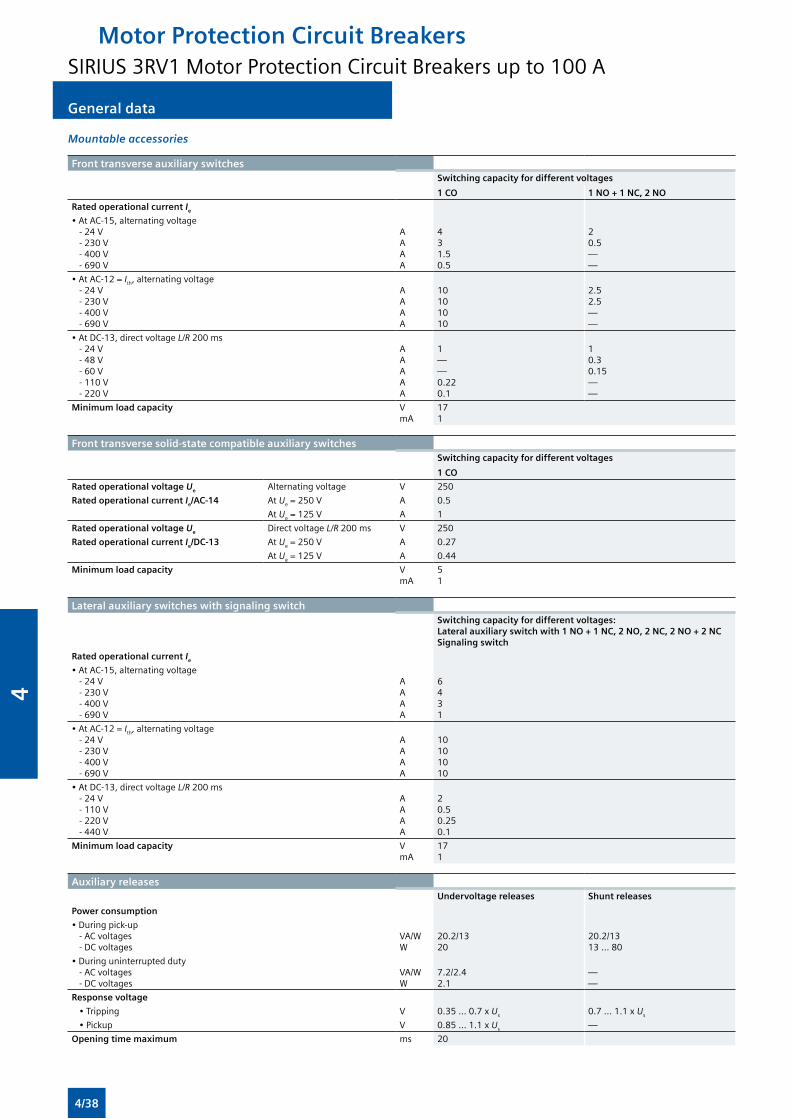
General dataGeneral data
Mountable accessories
Front transverse auxiliary switchesSwitching capacity for different voltages
1 CO 1 NO + 1 NC, 2 NO
Rated operational current Ie
• At AC-15, alternating voltage - 24 V - 230 V - 400 V - 690 V
AAAA
431.50.5
20.5——
• At AC-12 = Ith, alternating voltage - 24 V - 230 V - 400 V - 690 V
AAAA
10101010
2.52.5——
• At DC-13, direct voltage L/R 200 ms - 24 V - 48 V - 60 V - 110 V - 220 V
AAAAA
1——0.220.1
10.30.15——
Minimum load capacity VmA
171
Front transverse solid-state compatible auxiliary switches Switching capacity for different voltages
1 CO
Rated operational voltage Ue Alternating voltage V 250
Rated operational current Ie/AC-14 At Ue = 250 V A 0.5
At Ue = 125 V A 1
Rated operational voltage Ue Direct voltage L/R 200 ms V 250
Rated operational current Ie/DC-13 At Ue = 250 V A 0.27
At Ue = 125 V A 0.44
Minimum load capacity VmA
51
Lateral auxiliary switches with signaling switchSwitching capacity for different voltages: Lateral auxiliary switch with 1 NO + 1 NC, 2 NO, 2 NC, 2 NO + 2 NCSignaling switch
Rated operational current Ie
• At AC-15, alternating voltage - 24 V - 230 V - 400 V - 690 V
AAAA
6431
• At AC-12 = Ith, alternating voltage - 24 V - 230 V - 400 V - 690 V
AAAA
10101010
• At DC-13, direct voltage L/R 200 ms - 24 V - 110 V - 220 V - 440 V
AAAA
20.50.250.1
Minimum load capacity VmA
171
Auxiliary releasesUndervoltage releases Shunt releases
Power consumption
• During pick-up - AC voltages - DC voltages
VA/WW
20.2/1320
20.2/1313 ... 80
• During uninterrupted duty - AC voltages - DC voltages
VA/WW
7.2/2.42.1
——
Response voltage
• Tripping V 0.35 ... 0.7 x Us 0.7 ... 1.1 x Us
• Pickup V 0.85 ... 1.1 x Us —
Opening time maximum ms 20
Motor Protection Circuit BreakersSIRIUS 3RV1 Motor Protection Circuit Breakers up to 100 A
4/38
4
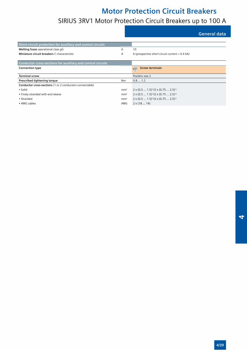
General data General data
Short-circuit protection for auxiliary and control circuitsMelting fuses operational class gG A 10
Miniature circuit breakers C characteristic A 6 (prospective short-circuit current < 0.4 kA)
Conductor cross-sections for auxiliary and control circuitsConnection type Screw terminals
Terminal screw Pozidriv size 2
Prescribed tightening torque Nm 0.8 ... 1.2
Conductor cross-sections (1 or 2 conductors connectable)
• Solid mm2 2 x (0.5 ... 1.5)1)/2 x (0.75 ... 2.5)1)
• Finely stranded with end sleeve mm2 2 x (0.5 ... 1.5)1)/2 x (0.75 ... 2.5)1)
• Stranded mm2 2 x (0.5 ... 1.5)1)/2 x (0.75 ... 2.5)1)
• AWG cables AWG 2 x (18 ... 14)
Motor Protection Circuit BreakersSIRIUS 3RV1 Motor Protection Circuit Breakers up to 100 A
4/39
4
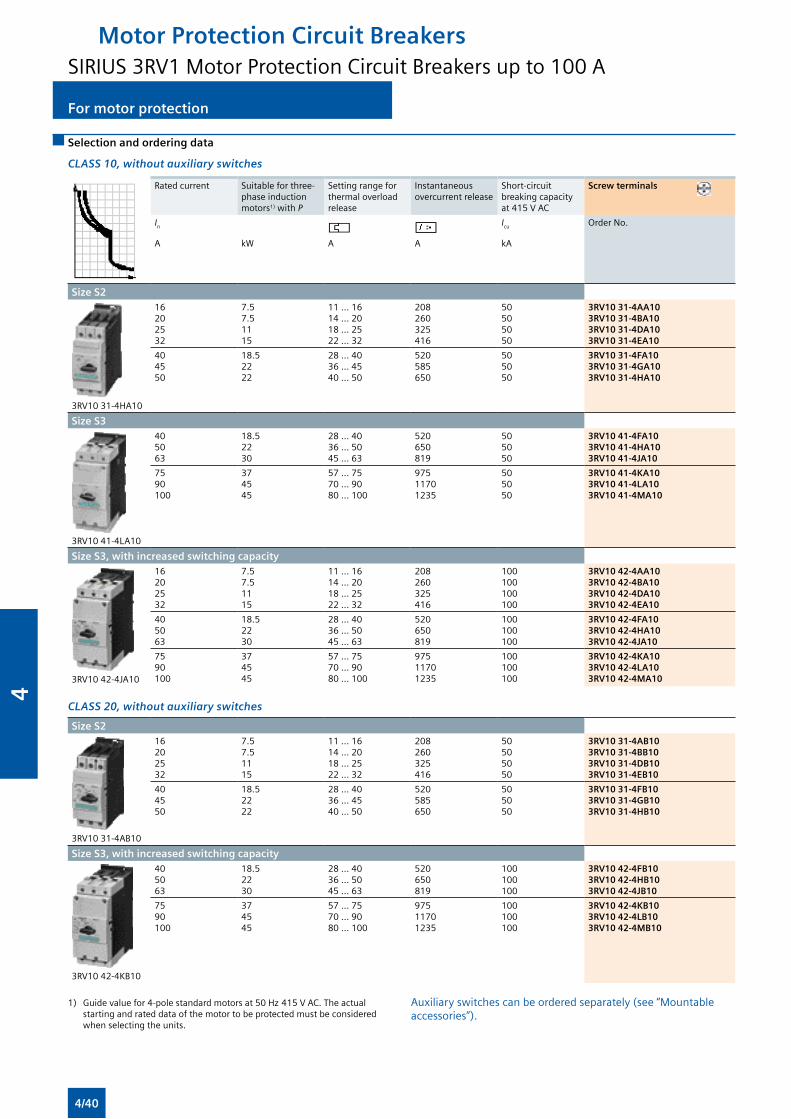
For motor protectionFor motor protection
Selection and ordering data
CLASS 10, without auxiliary switches
Rated current Suitable for three-phase induction motors1) with P
Setting range for thermal overload release
Instantaneous overcurrent release
Short-circuit breaking capacity at 415 V AC
Screw terminals
In Icu Order No.
A kW A A kA
Size S2
3RV10 31-4HA10
16202532
7.57.51115
11 ... 1614 ... 2018 ... 2522 ... 32
208260325416
50505050
3RV10 31-4AA103RV10 31-4BA103RV10 31-4DA103RV10 31-4EA10
404550
18.52222
28 ... 4036 ... 4540 ... 50
520585650
505050
3RV10 31-4FA103RV10 31-4GA103RV10 31-4HA10
Size S3
3RV10 41-4LA10
405063
18.52230
28 ... 4036 ... 5045 ... 63
520650819
505050
3RV10 41-4FA103RV10 41-4HA103RV10 41-4JA10
7590100
374545
57 ... 7570 ... 9080 ... 100
97511701235
505050
3RV10 41-4KA103RV10 41-4LA103RV10 41-4MA10
Size S3, with increased switching capacity
3RV10 42-4JA10
16202532
7.57.51115
11 ... 1614 ... 2018 ... 2522 ... 32
208260325416
100100100100
3RV10 42-4AA103RV10 42-4BA103RV10 42-4DA103RV10 42-4EA10
405063
18.52230
28 ... 4036 ... 5045 ... 63
520650819
100100100
3RV10 42-4FA103RV10 42-4HA103RV10 42-4JA10
7590100
374545
57 ... 7570 ... 9080 ... 100
97511701235
100100100
3RV10 42-4KA103RV10 42-4LA103RV10 42-4MA10
CLASS 20, without auxiliary switches
Size S2
3RV10 31-4AB10
16202532
7.57.51115
11 ... 1614 ... 2018 ... 2522 ... 32
208260325416
50505050
3RV10 31-4AB103RV10 31-4BB103RV10 31-4DB103RV10 31-4EB10
404550
18.52222
28 ... 4036 ... 4540 ... 50
520585650
505050
3RV10 31-4FB103RV10 31-4GB103RV10 31-4HB10
Size S3, with increased switching capacity
3RV10 42-4KB10
405063
18.52230
28 ... 4036 ... 5045 ... 63
520650819
100100100
3RV10 42-4FB103RV10 42-4HB103RV10 42-4JB10
7590100
374545
57 ... 7570 ... 9080 ... 100
97511701235
100100100
3RV10 42-4KB103RV10 42-4LB103RV10 42-4MB10
1) Guide value for 4-pole standard motors at 50 Hz 415 V AC. The actual starting and rated data of the motor to be protected must be considered when selecting the units.
Auxiliary switches can be ordered separately (see “Mountable accessories”).
Motor Protection Circuit BreakersSIRIUS 3RV1 Motor Protection Circuit Breakers up to 100 A
4/40
4
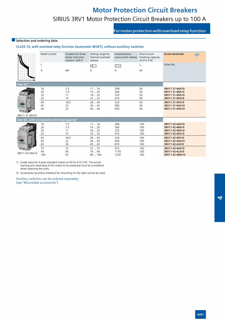
For motor protection with overload relay function For motor protection with overload relay function
Selection and ordering data
CLASS 10, with overload relay function (automatic RESET), without auxiliary switches
Rated current Suitable for three-phase induction motors1) with P
Setting range for thermal overload release
Instantaneous overcurrent release
Short-circuit breaking capacity at 415 V AC
Screw terminals
In Icu Order No.
A kW A A kA
Size S22)
3RV11 31-4EA10
16202532
7.57.51115
11 ... 1614 ... 2018 ... 2522 ... 32
208260325416
50505050
3RV11 31-4AA10 3RV11 31-4BA10 3RV11 31-4DA10 3RV11 31-4EA10
404550
18.52222
28 ... 4036 ... 4540 ... 50
520585650
505050
3RV11 31-4FA10 3RV11 31-4GA10 3RV11 31-4HA10
Size S3, with increased switching capacity2)
3RV11 42-4AA10
16202532
7.57.51115
11 ... 1614 ... 2018 ... 2522 ... 32
208260325416
100100100100
3RV11 42-4AA10 3RV11 42-4BA10 3RV11 42-4DA10 3RV11 42-4EA10
405063
18.52230
28 ... 4036 ... 5045 ... 63
520650819
100100100
3RV11 42-4FA10 3RV11 42-4HA10 3RV11 42-4JA10
7590100
374545
57 ... 7570 ... 9080 ... 100
97511701235
100100100
3RV11 42-4KA10 3RV11 42-4LA10 3RV11 42-4MA10
1) Guide value for 4-pole standard motors at 50 Hz 415 V AC. The actual starting and rated data of the motor to be protected must be considered when selecting the units.
2) Accessories (auxiliary releases) for mounting on the right cannot be used.
Auxiliary switches can be ordered separately (see “Mountable accessories”).
Motor Protection Circuit BreakersSIRIUS 3RV1 Motor Protection Circuit Breakers up to 100 A
4/41
4
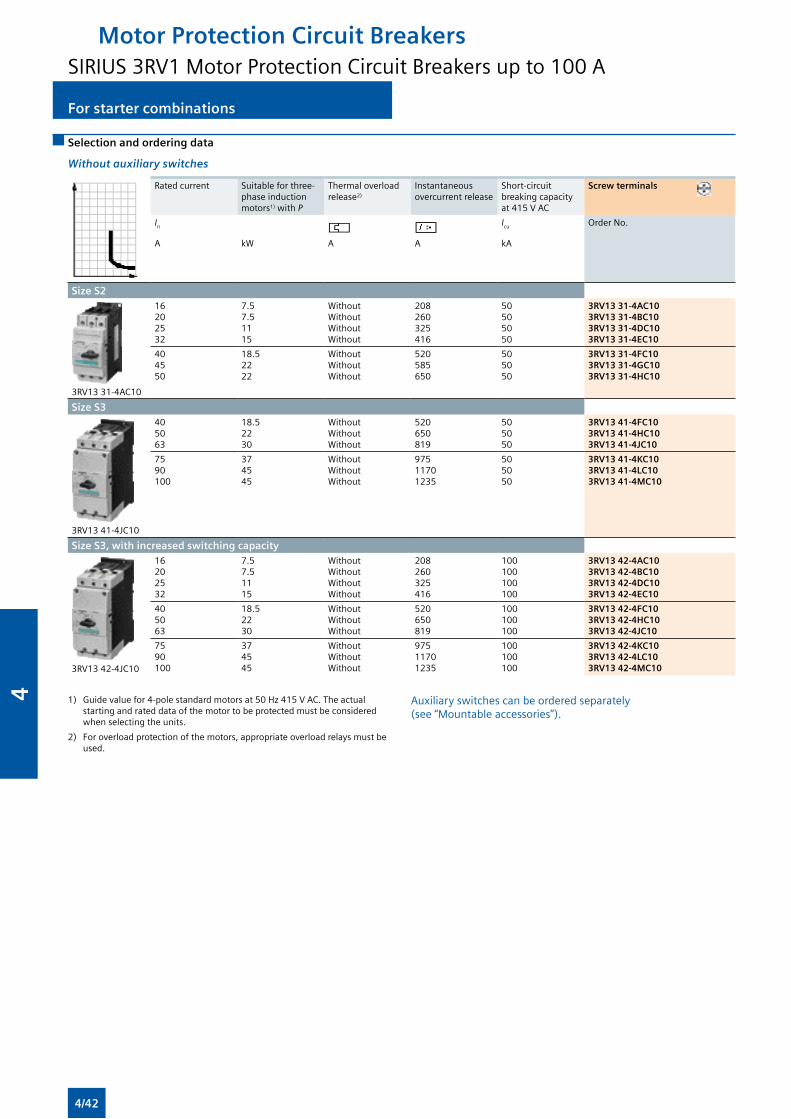
For starter combinationsFor starter combinations
Selection and ordering data
Without auxiliary switches
Rated current Suitable for three-phase induction motors1) with P
Thermal overload release2)
Instantaneous overcurrent release
Short-circuit breaking capacity at 415 V AC
Screw terminals
In Icu Order No.
A kW A A kA
Size S2
3RV13 31-4AC10
16202532
7.57.51115
WithoutWithoutWithoutWithout
208260325416
50505050
3RV13 31-4AC10 3RV13 31-4BC10 3RV13 31-4DC10 3RV13 31-4EC10
404550
18.52222
WithoutWithoutWithout
520585650
505050
3RV13 31-4FC10 3RV13 31-4GC10 3RV13 31-4HC10
Size S3
3RV13 41-4JC10
405063
18.52230
WithoutWithoutWithout
520650819
505050
3RV13 41-4FC10 3RV13 41-4HC10 3RV13 41-4JC10
7590100
374545
WithoutWithoutWithout
97511701235
505050
3RV13 41-4KC10 3RV13 41-4LC10 3RV13 41-4MC10
Size S3, with increased switching capacity
3RV13 42-4JC10
16202532
7.57.51115
WithoutWithoutWithoutWithout
208260325416
100100100100
3RV13 42-4AC10 3RV13 42-4BC10 3RV13 42-4DC10 3RV13 42-4EC10
405063
18.52230
WithoutWithoutWithout
520650819
100100100
3RV13 42-4FC10 3RV13 42-4HC10 3RV13 42-4JC10
7590100
374545
WithoutWithoutWithout
97511701235
100100100
3RV13 42-4KC10 3RV13 42-4LC10 3RV13 42-4MC10
1) Guide value for 4-pole standard motors at 50 Hz 415 V AC. The actual starting and rated data of the motor to be protected must be considered when selecting the units.
2) For overload protection of the motors, appropriate overload relays must be used.
Auxiliary switches can be ordered separately (see “Mountable accessories”).
Motor Protection Circuit BreakersSIRIUS 3RV1 Motor Protection Circuit Breakers up to 100 A
4/42
4
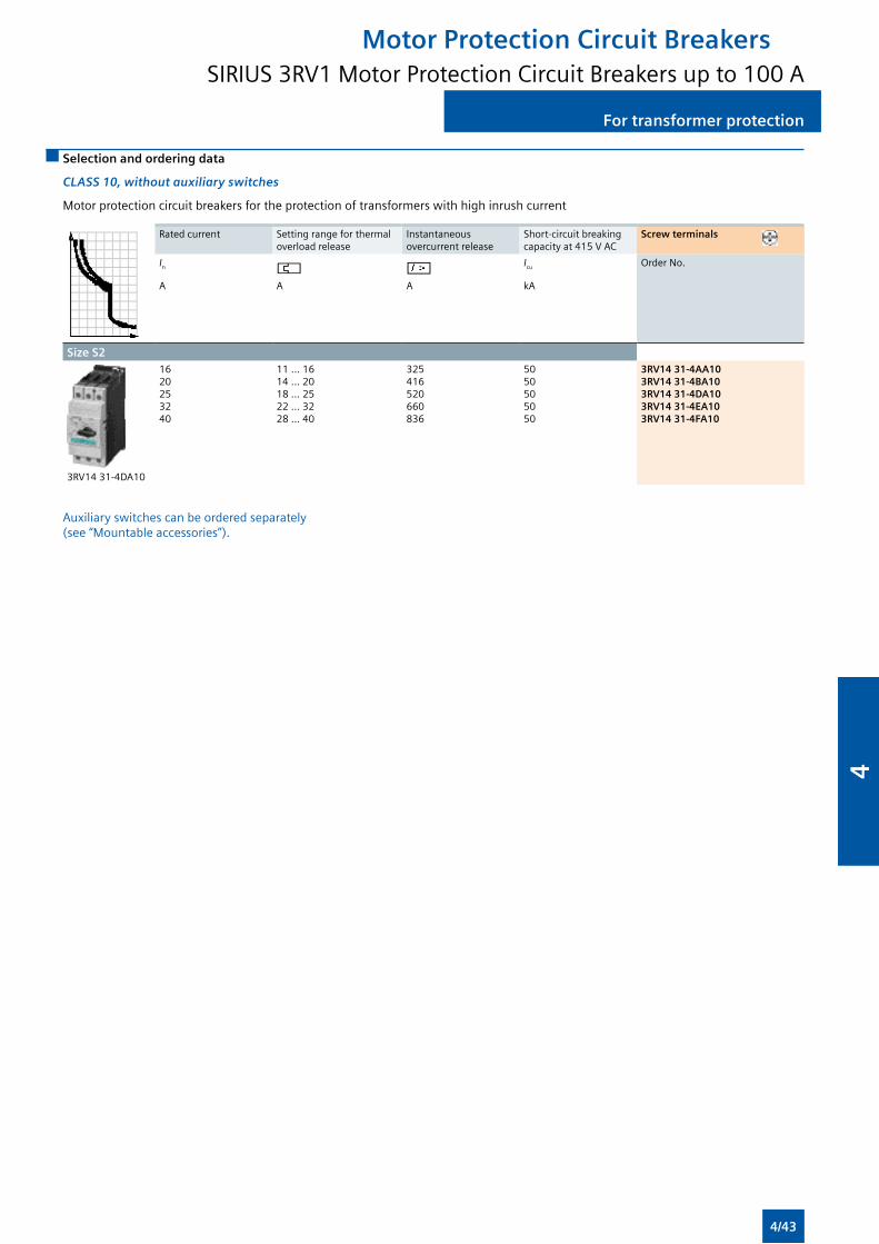
For transformer protection For transformer protection
Selection and ordering data
CLASS 10, without auxiliary switches
Motor protection circuit breakers for the protection of transformers with high inrush current
Rated current Setting range for thermal overload release
Instantaneous overcurrent release
Short-circuit breaking capacity at 415 V AC
Screw terminals
In Icu Order No.
A A A kA
Size S2
3RV14 31-4DA10
1620253240
11 ... 1614 ... 2018 ... 2522 ... 3228 ... 40
325416520660836
5050505050
3RV14 31-4AA10 3RV14 31-4BA10 3RV14 31-4DA10 3RV14 31-4EA10 3RV14 31-4FA10
Auxiliary switches can be ordered separately (see “Mountable accessories”).
Motor Protection Circuit BreakersSIRIUS 3RV1 Motor Protection Circuit Breakers up to 100 A
4/43
4
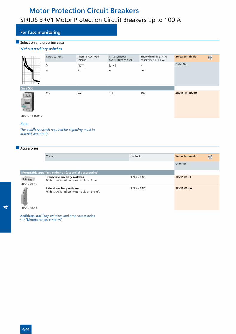
For fuse monitoringFor fuse monitoring
Selection and ordering data
Without auxiliary switches
Rated current Thermal overload release
Instantaneous overcurrent release
Short-circuit breaking capacity at 415 V AC
Screw terminals
In Icu Order No.
A A A kA
Size S00
3RV16 11-0BD10
0.2 0.2 1.2 100 3RV16 11-0BD10
Note:
Theauxiliaryswitchrequiredforsignalingmustbe ordered separately.
Accessories
Version Contacts Screw terminals
Order No.
Mountable auxiliary switches (essential accessories)
3RV19 01-1E
Transverse auxiliary switches With screw terminals, mountable on front
1 NO + 1 NC 3RV19 01-1E
3RV19 01-1A
Lateral auxiliary switches With screw terminals, mountable on the left
1 NO + 1 NC 3RV19 01-1A
Additional auxiliary switches and other accessories see “Mountable accessories”.
Motor Protection Circuit BreakersSIRIUS 3RV1 Motor Protection Circuit Breakers up to 100 A
4/44
4
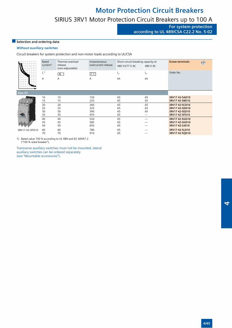
For system protectionaccording to UL 489/CSA C22.2 No. 5-02
For system protectionaccording to UL 489/CSA C22.2 No. 5-02
Selection and ordering data
Without auxiliary switches
Circuit breakers for system protection and non-motor loads according to UL/CSA
Rated current1)
Thermal overload release (non-adjustable)
Instantaneous overcurrent release
Short-circuit breaking capacity at Screw terminals
480 Y/277 V AC 480 V AC
In1) Ibc Ibc Order No.
A A A kA kA
Size S3
3RV17 42-5FD10
1015
1015
150225
6565
6565
3RV17 42-5AD103RV17 42-5BD10
20253035
20253035
260325390455
65656565
656565—
3RV17 42-5CD103RV17 42-5DD103RV17 42-5ED103RV17 42-5FD10
404550
404550
520585650
656565
———
3RV17 42-5GD103RV17 42-5HD103RV17 42-5JD10
6070
6070
780910
6565
——
3RV17 42-5LD103RV17 42-5QD10
1) Rated value 100 % according to UL 489 and IEC 60947-2 (“100 % rated breaker”).
Transverse auxiliary switches must not be mounted, lateral auxiliary switches can be ordered separately (see “Mountable accessories”).
Motor Protection Circuit BreakersSIRIUS 3RV1 Motor Protection Circuit Breakers up to 100 A
4/45
4
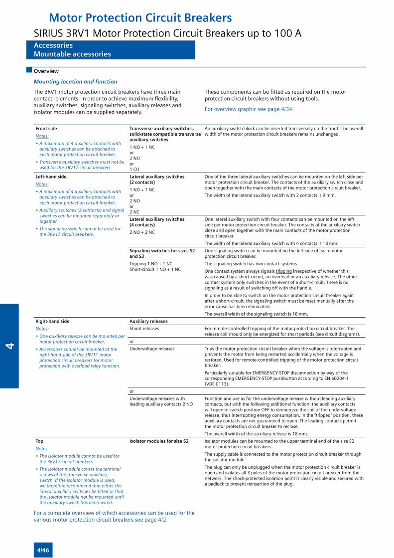
AccessoriesMountable accessories
AccessoriesMountable accessories
Overview
Mounting location and function
The 3RV1 motor protection circuit breakers have three main contact -elements. In order to achieve maximum flexibility, auxiliary switches, signaling switches, auxiliary releases and isolator modules can be supplied separately.
These components can be fitted as required on the motor protection circuit breakers without using tools.
For overview graphic see page 4/34.
Front side
Notes:
•Amaximumof4auxiliarycontactswithauxiliaryswitchescanbeattachedtoeach motor protection circuit breaker.
•Transverseauxiliaryswitchesmustnotbeusedforthe3RV17circuitbreakers.
Transverse auxiliary switches, solid-state compatible transverse auxiliary switches
1 NO + 1 NC or 2 NO or 1 CO
An auxiliary switch block can be inserted transversely on the front. The overall width of the motor protection circuit breakers remains unchanged.
Left-hand side
Notes:
•Amaximumof4auxiliarycontactswithauxiliaryswitchescanbeattachedtoeach motor protection circuit breaker.
•Auxiliaryswitches(2contacts)andsignalswitchescanbemountedseparatelyortogether.
•Thesignalingswitchcannotbeusedforthe3RV17circuitbreakers.
Lateral auxiliary switches (2 contacts)
1 NO + 1 NC or 2 NO or 2 NC
One of the three lateral auxiliary switches can be mounted on the left side per motor protection circuit breaker. The contacts of the auxiliary switch close and open together with the main contacts of the motor protection circuit breaker.
The width of the lateral auxiliary switch with 2 contacts is 9 mm.
Lateral auxiliary switches (4 contacts)
2 NO + 2 NC
One lateral auxiliary switch with four contacts can be mounted on the left side per motor protection circuit breaker. The contacts of the auxiliary switch close and open together with the main contacts of the motor protection circuit breaker.
The width of the lateral auxiliary switch with 4 contacts is 18 mm.
Signaling switches for sizes S2 and S3
Tripping 1 NO + 1 NC Short-circuit 1 NO + 1 NC
One signaling switch can be mounted on the left side of each motor protection circuit breaker.
The signaling switch has two contact systems.
One contact system always signals tripping irrespective of whether this was caused by a short-circuit, an overload or an auxiliary release. The other contact system only switches in the event of a short-circuit. There is no signaling as a result of switching off with the handle.
In order to be able to switch on the motor protection circuit breaker again after a short-circuit, the signaling switch must be reset manually after the error cause has been eliminated.
The overall width of the signaling switch is 18 mm.
Right-hand side
Notes:
•Oneauxiliaryreleasecanbemountedpermotor protection circuit breaker.
•Accessoriescannotbemountedattheright-handsideofthe3RV11motorprotection circuit breakers for motor protectionwithoverloadrelayfunction.
Auxiliary releases
Shunt releases For remote-controlled tripping of the motor protection circuit breaker. The release coil should only be energized for short periods (see circuit diagrams).
or
Undervoltage releases Trips the motor protection circuit breaker when the voltage is interrupted and prevents the motor from being restarted accidentally when the voltage is restored. Used for remote-controlled tripping of the motor protection circuit breaker.
Particularly suitable for EMERGENCY-STOP disconnection by way of the corresponding EMERGENCY-STOP pushbutton according to EN 60204-1 (VDE 0113).
or
Undervoltage releases with leading auxiliary contacts 2 NO
Function and use as for the undervoltage release without leading auxiliary contacts, but with the following additional function: the auxiliary contacts will open in switch position OFF to deenergize the coil of the undervoltage release, thus interrupting energy consumption. In the “tripped” position, these auxiliary contacts are not guaranteed to open. The leading contacts permit the motor protection circuit breaker to reclose.
The overall width of the auxiliary release is 18 mm.
Top
Notes:
•Theisolatormodulecannotbeusedforthe3RV17circuitbreakers.
•Theisolatormodulecoverstheterminalscrewsofthetransverseauxiliaryswitch.Iftheisolatormoduleisused,wethereforerecommendthateitherthelateralauxiliaryswitchesbefittedorthatthe isolator module not be mounted until theauxiliaryswitchhasbeenwired.
Isolator modules for size S2 Isolator modules can be mounted to the upper terminal end of the size S2 motor protection circuit breakers.
The supply cable is connected to the motor protection circuit breaker through the isolator module.
The plug can only be unplugged when the motor protection circuit breaker is open and isolates all 3 poles of the motor protection circuit breaker from the network. The shock-protected isolation point is clearly visible and secured with a padlock to prevent reinsertion of the plug.
For a complete overview of which accessories can be used for the various motor protection circuit breakers see page 4/2.
Motor Protection Circuit BreakersSIRIUS 3RV1 Motor Protection Circuit Breakers up to 100 A
4/46
4
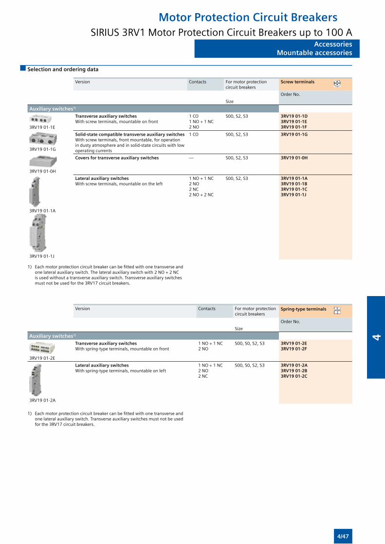
AccessoriesMountable accessories
AccessoriesMountable accessories
Selection and ordering data
Version Contacts For motor protection circuit breakers
Screw terminals
Order No.
Size
Auxiliary switches1)
3RV19 01-1E
Transverse auxiliary switchesWith screw terminals, mountable on front
1 CO1 NO + 1 NC2 NO
S00, S2, S3 3RV19 01-1D3RV19 01-1E3RV19 01-1F
3RV19 01-1G
Solid-state compatible transverse auxiliary switchesWith screw terminals, front mountable, for operation in dusty atmosphere and in solid-state circuits with low operating currents
1 CO S00, S2, S3 3RV19 01-1G
3RV19 01-0H
Covers for transverse auxiliary switches — S00, S2, S3 3RV19 01-0H
3RV19 01-1A
3RV19 01-1J
Lateral auxiliary switchesWith screw terminals, mountable on the left
1 NO + 1 NC2 NO2 NC2 NO + 2 NC
S00, S2, S3 3RV19 01-1A3RV19 01-1B3RV19 01-1C3RV19 01-1J
1) Each motor protection circuit breaker can be fitted with one transverse and one lateral auxiliary switch. The lateral auxiliary switch with 2 NO + 2 NC is used without a transverse auxiliary switch. Transverse auxiliary switches must not be used for the 3RV17 circuit breakers.
Version Contacts For motor protection circuit breakers
Spring-type terminals
Order No.
Size
Auxiliary switches1)
3RV19 01-2E
Transverse auxiliary switches With spring-type terminals, mountable on front
1 NO + 1 NC2 NO
S00, S0, S2, S3 3RV19 01-2E3RV19 01-2F
3RV19 01-2A
Lateral auxiliary switches With spring-type terminals, mountable on left
1 NO + 1 NC2 NO2 NC
S00, S0, S2, S3 3RV19 01-2A3RV19 01-2B3RV19 01-2C
1) Each motor protection circuit breaker can be fitted with one transverse and one lateral auxiliary switch. Transverse auxiliary switches must not be used for the 3RV17 circuit breakers.
Motor Protection Circuit BreakersSIRIUS 3RV1 Motor Protection Circuit Breakers up to 100 A
4/47
4
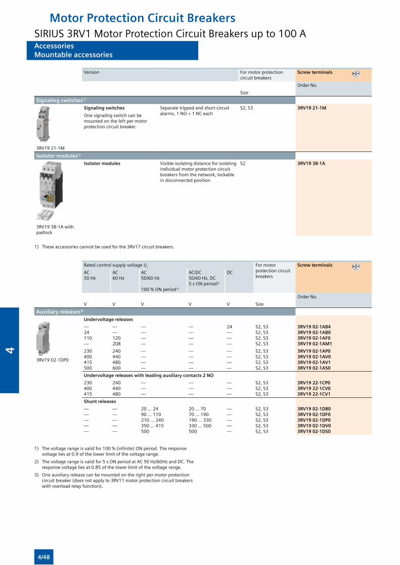
AccessoriesMountable accessories
AccessoriesMountable accessories
Version For motor protection circuit breakers
Screw terminals
Order No.
Size
Signaling switches1)
3RV19 21-1M
Signaling switches
One signaling switch can be mounted on the left per motor protection circuit breaker.
Separate tripped and short-circuit alarms, 1 NO + 1 NC each
S2, S3 3RV19 21-1M
Isolator modules1)
3RV19 38-1A with padlock
Isolator modules Visible isolating distance for isolating individual motor protection circuit breakers from the network, lockable in disconnected position
S2 3RV19 38-1A
1) These accessories cannot be used for the 3RV17 circuit breakers.
Rated control supply voltage Us For motor protection circuit breakers
Screw terminals
AC50 Hz
AC60 Hz
AC50/60 Hz
100 % ON period1)
AC/DC50/60 Hz, DC 5 s ON period2)
DC
Order No.
V V V V V Size
Auxiliary releases3)
3RV19 02-1DP0
Undervoltage releases
—24110—
——120208
— — — —
— — — —
24———
S2, S3S2, S3S2, S3S2, S3
3RV19 02-1AB43RV19 02-1AB03RV19 02-1AF03RV19 02-1AM1
230400415500
240440480600
— — — —
— — ——
————
S2, S3S2, S3S2, S3S2, S3
3RV19 02-1AP03RV19 02-1AV03RV19 02-1AV13RV19 02-1AS0
Undervoltage releases with leading auxiliary contacts 2 NO
230400415
240440480
— — —
— — —
———
S2, S3S2, S3S2, S3
3RV19 22-1CP03RV19 22-1CV03RV19 22-1CV1
Shunt releases
—————
—————
20 ... 2490 ... 110210 ... 240350 ... 415500
20 ... 7070 ... 190190 ... 330330 ... 500500
—————
S2, S3S2, S3S2, S3S2, S3S2, S3
3RV19 02-1DB03RV19 02-1DF03RV19 02-1DP03RV19 02-1DV03RV19 02-1DS0
1) The voltage range is valid for 100 % (infinite) ON period. The response voltage lies at 0.9 of the lower limit of the voltage range.
2) The voltage range is valid for 5 s ON period at AC 50 Hz/60Hz and DC. The response voltage lies at 0.85 of the lower limit of the voltage range.
3) One auxiliary release can be mounted on the right per motor protection circuit breaker (does not apply to 3RV11 motor protection circuit breakers with overload relay function).
Motor Protection Circuit BreakersSIRIUS 3RV1 Motor Protection Circuit Breakers up to 100 A
4/48
4
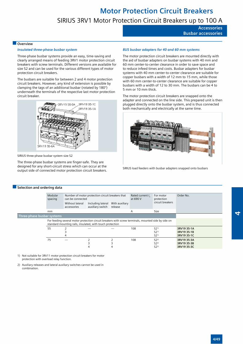
AccessoriesBusbar accessories
AccessoriesBusbar accessories
Overview
Insulated three-phase busbar system
Three-phase busbar systems provide an easy, time-saving and clearly arranged means of feeding 3RV1 motor protection circuit breakers with screw terminals. Different versions are available for size S2 and can be used for the various different types of motor protection circuit breakers.
The busbars are suitable for between 2 and 4 motor protection circuit breakers. However, any kind of extension is possible by clamping the tags of an additional busbar (rotated by 180°) underneath the terminals of the respective last motor protection circuit breaker.
SIRIUS three-phase busbar system size S2
The three-phase busbar systems are finger-safe. They are designed for any short-circuit stress which can occur at the output side of connected motor protection circuit breakers.
8US busbar adapters for 40 and 60 mm systems
The motor protection circuit breakers are mounted directly with the aid of busbar adapters on busbar systems with 40 mm and 60 mm center-to-center clearance in order to save space and to reduce infeed times and costs. Busbar adapters for busbar systems with 40 mm center-to-center clearance are suitable for copper busbars with a width of 12 mm to 15 mm, while those with 60 mm center-to-center clearance are suitable for copper busbars with a width of 12 to 30 mm. The busbars can be 4 to 5 mm or 10 mm thick.
The motor protection circuit breakers are snapped onto the adapter and connected on the line side. This prepared unit is then plugged directly onto the busbar system, and is thus connected both mechanically and electrically at the same time.
SIRIUS load feeders with busbar adapters snapped onto busbars
Selection and ordering data
Modular spacing
Number of motor protection circuit breakers that can be connected
Rated current In at 690 V
For motor protection circuit breakers
Order No.
Without lateral accessories
Including lateral auxiliary switch
With auxiliary release
mm A Size
Three-phase busbar systemsFor feeding several motor protection circuit breakers with screw terminals, mounted side by side on standard mounting rails, insulated, with touch protection
55 234
— — 108 S21)
S21)
S21)
3RV19 35-1A3RV19 35-1B3RV19 35-1C
75 — 234
234
108 S22)
S22)
S22)
3RV19 35-3A3RV19 35-3B3RV19 35-3C
1) Not suitable for 3RV11 motor protection circuit breakers for motor protection with overload relay function.
2) Auxiliary releases and lateral auxiliary switches cannot be used in combination.
Motor Protection Circuit BreakersSIRIUS 3RV1 Motor Protection Circuit Breakers up to 100 A
4/49
4
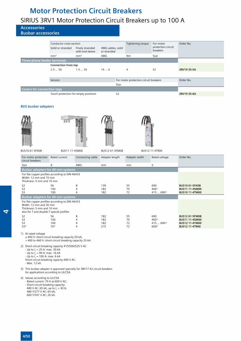
AccessoriesBusbar accessories
AccessoriesBusbar accessories
Conductor cross-section Tightening torque For motor protection circuit breakers
Order No.
Solid or stranded Finely stranded with end sleeve
AWG cables, solid or stranded
mm² mm² AWG Nm Size
Three-phase feeder terminals Connection from top
2.5 ... 50 1.5 ... 35 14 ... 0 4 S2 3RV19 35-5A
Version For motor protection circuit breakers Order No.
Size
Covers for connection tagsTouch protection for empty positions S2 3RV19 35-6A
8US busbar adapters
8US10 61-5FK08 8US11 11-4SM00 8US12 61-5FM08 8US12 11-4TR00
For motor protection circuit breakers
Rated current Connecting cable Adapter length Adapter width Rated voltage Order No.
Size A AWG mm mm V
Busbar adapters for 40 mm systemsFor flat copper profiles according to DIN 46433 Width: 12 mm and 15 mm Thickness: 5 mm and 10 mm
S2S3S3
56100100
844
139182182
557072
6904001)
415 ... 6902)
8US10 61-5FK088US11 11-4SM008US10 11-4TM00
Busbar adapters for 60 mm systemsFor flat copper profiles according to DIN 46433 Width: 12 mm and 30 mm Thickness: 5 mm and 10 mm also for T and double-T special profiles
S2S3S3S33)
56100100704)
8444
182182182215
55707272
6904001)
415 ... 6902)
6004)
8US12 61-5FM088US11 11-4SM008US12 11-4TM008US12 11-4TR00
1) At rated voltage ≤ 400 V: short-circuit breaking capacity 50 kA, > 400 to 460 V: short-circuit breaking capacity 25 kA.
2) Short-circuit breaking capacity 415/500/525 V AC - Up to In = 25 A: max. 30 kA - Up to In = 90 A: max. 16 kA - Up to In = 100 A: max. 6 kA Short-circuit breaking capacity 690 V AC: - Max. 12 kA.
3) This busbar adapter is approved specially for 3RV17 42 circuit breakers for applications according to UL/CSA.
4) Values according to UL/CSA - Rated current: 70 A at 600 V AC; - Short-circuit breaking capacity: 480 V AC: 65 kA, up to In = 30 A; 480 Y/277 V AC: 65 kA; 600 Y/347 V AC: 20 kA.
Motor Protection Circuit BreakersSIRIUS 3RV1 Motor Protection Circuit Breakers up to 100 A
4/50
4
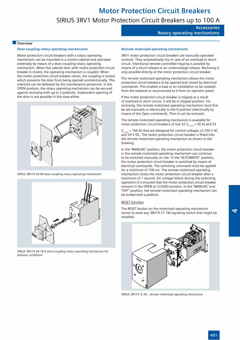
AccessoriesRotary operating mechanisms
AccessoriesRotary operating mechanisms
Overview
Door-coupling rotary operating mechanisms
Motor protection circuit breakers with a rotary operating mechanism can be mounted in a control cabinet and operated externally by means of a door-coupling rotary operating mechanism. When the cabinet door with motor protection circuit breaker is closed, the operating mechanism is coupled. When the motor protection circuit breaker closes, the coupling is locked which prevents the door from being opened unintentionally. This interlock can be defeated by the maintenance personnel. In the OPEN position, the rotary operating mechanism can be secured against reclosing with up to 3 padlocks. Inadvertent opening of the door is not possible in this case either.
SIRIUS 3RV19 26-0K door-coupling rotary operating mechanism
SIRIUS 3RV19 36-1B-Z door-coupling rotary operating mechanism for arduous conditions
Remote motorized operating mechanisms
3RV1 motor protection circuit breakers are manually operated controls. They automatically trip in case of an overload or short-circuit. Intentional remote-controlled tripping is possible by means of a shunt release or an undervoltage release. Reclosing is only possible directly at the motor protection circuit breaker.
The remote motorized operating mechanism allows the motor protection circuit breakers to be opened and closed by electrical commands. This enables a load or an installation to be isolated from the network or reconnected to it from an operator panel.
If the motor protection circuit breaker is tripped as a result of overload or short-circuit, it will be in tripped position. For reclosing, the remote motorized operating mechanism must first be set manually or electrically to the 0 position (electrically by means of the Open command). Then it can be reclosed.
The remote motorized operating mechanism is available for motor protection circuit breakers of size S2 (In max = 50 A) and S3
(In max = 100 A) that are designed for control voltages of 230 V AC and 24 V DC. The motor protection circuit breaker is fitted into the remote motorized operating mechanism as shown in the drawing.
In the “MANUAL” position, the motor protection circuit breaker in the remote motorized operating mechanism can continue to be switched manually on site. In the “AUTOMATIC” position, the motor protection circuit breaker is switched by means of electrical commands. The switching command must be applied for a minimum of 100 ms. The remote motorized operating mechanism closes the motor protection circuit breaker after a maximum of 1 second. On voltage failure during the switching operation it is ensured that the motor protection circuit breaker remains in the OPEN or CLOSED position. In the “MANUAL” and “OFF” position, the remote motorized operating mechanism can be locked with a padlock.
RESET function
The RESET button on the motorized operating mechanism serves to reset any 3RV19 21-1M signaling switch that might be installed.
SIRIUS 3RV19 .6-3A.. remote motorized operating mechanism
Motor Protection Circuit BreakersSIRIUS 3RV1 Motor Protection Circuit Breakers up to 100 A
4/51
4
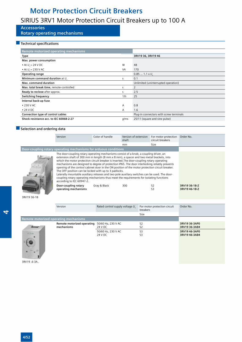
AccessoriesRotary operating mechanisms
AccessoriesRotary operating mechanisms
Technical specifications
Remote motorized operating mechanismsType 3RV19 36, 3RV19 46
Max. power consumption
• At Us = 24 V DC
• At Us = 230 V AC
W
VA
48
170
Operating range 0.85 ... 1.1 x Us
Minimum command duration at Us s 0.1
Max. command duration Unlimited (uninterrupted operation)
Max. total break time, remote-controlled s 2
Ready to reclose after approx. s 2.5
Switching frequency 1/h 25
Internal back-up fuse
• 230 V AC
• 24 V DC
A
A
0.8
1.6
Connection type of control cables Plug-in connectors with screw terminals
Shock resistance acc. to IEC 60068-2-27 g/ms 25/11 (square and sine pulse)
Selection and ordering data
Version Color of handle Version of extension shaft
For motor protection circuit breakers
Order No.
mm Size
Door-coupling rotary operating mechanisms for arduous conditions
3RV19 36-1B
The door-coupling rotary operating mechanisms consist of a knob, a coupling driver, an extension shaft of 300 mm in length (8 mm x 8 mm), a spacer and two metal brackets, into which the motor protection circuit breaker is inserted.The door-coupling rotary operating mechanisms are designed to degree of protection IP65. The door interlocking reliably prevents opening of the control cabinet door in the ON position of the motor protection circuit breaker. The OFF position can be locked with up to 3 padlocks.Laterally mountable auxiliary releases and two-pole auxiliary switches can be used. The door-coupling rotary operating mechanisms thus meet the requirements for isolating functions according to IEC 60947-2.
Door-coupling rotary operating mechanisms
Gray & Black 300 S2S3
3RV19 36-1B-Z3RV19 46-1B-Z
Version Rated control supply voltage Us For motor protection circuit breakers
Order No.
Size
Remote motorized operating mechanisms
3RV19 .6-3A..
Remote motorized operating mechanisms
50/60 Hz, 230 V AC24 V DC
S2S2
3RV19 36-3AP03RV19 36-3AB4
50/60 Hz, 230 V AC24 V DC
S3S3
3RV19 46-3AP03RV19 46-3AB4
Motor Protection Circuit BreakersSIRIUS 3RV1 Motor Protection Circuit Breakers up to 100 A
4/52
4
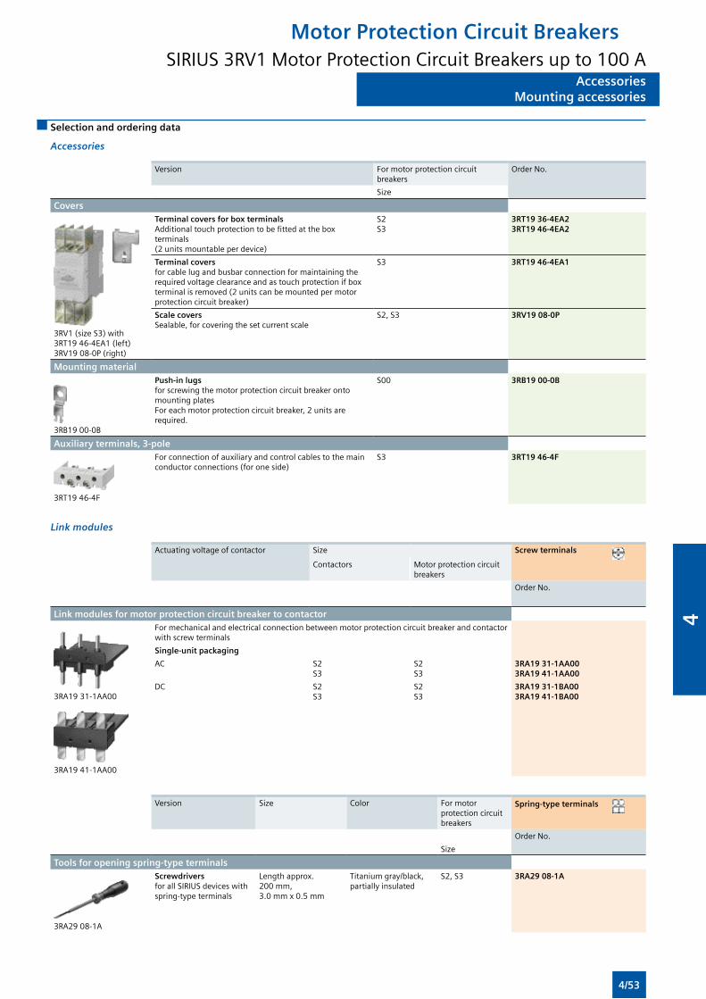
AccessoriesMounting accessories
AccessoriesMounting accessories
Selection and ordering data
Accessories
Version For motor protection circuit breakers
Order No.
Size
Covers
3RV1 (size S3) with 3RT19 46-4EA1 (left) 3RV19 08-0P (right)
Terminal covers for box terminalsAdditional touch protection to be fitted at the box terminals (2 units mountable per device)
S2S3
3RT19 36-4EA23RT19 46-4EA2
Terminal covers for cable lug and busbar connection for maintaining the required voltage clearance and as touch protection if box terminal is removed (2 units can be mounted per motor protection circuit breaker)
S3 3RT19 46-4EA1
Scale coversSealable, for covering the set current scale
S2, S3 3RV19 08-0P
Mounting material
3RB19 00-0B
Push-in lugsfor screwing the motor protection circuit breaker onto mounting platesFor each motor protection circuit breaker, 2 units are required.
S00 3RB19 00-0B
Auxiliary terminals, 3-pole
3RT19 46-4F
For connection of auxiliary and control cables to the main conductor connections (for one side)
S3 3RT19 46-4F
Link modules
Actuating voltage of contactor Size Screw terminals
Contactors Motor protection circuit breakers
Order No.
Link modules for motor protection circuit breaker to contactor
3RA19 31-1AA00
3RA19 41-1AA00
For mechanical and electrical connection between motor protection circuit breaker and contactor with screw terminals
Single-unit packaging
AC S2S3
S2S3
3RA19 31-1AA003RA19 41-1AA00
DC S2S3
S2S3
3RA19 31-1BA003RA19 41-1BA00
Version Size Color For motor protection circuit breakers
Spring-type terminals
Order No.
Size
Tools for opening spring-type terminals
3RA29 08-1A
Screwdrivers for all SIRIUS devices with spring-type terminals
Length approx. 200 mm, 3.0 mm x 0.5 mm
Titanium gray/black, partially insulated
S2, S3 3RA29 08-1A
Motor Protection Circuit BreakersSIRIUS 3RV1 Motor Protection Circuit Breakers up to 100 A
4/53
4
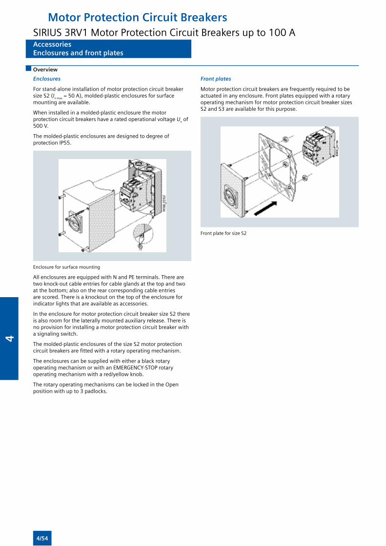
AccessoriesEnclosures and front plates
AccessoriesEnclosures and front plates
Overview
Enclosures
For stand-alone installation of motor protection circuit breaker size S2 (In max = 50 A), molded-plastic enclosures for surface mounting are available.
When installed in a molded-plastic enclosure the motor protection circuit breakers have a rated operational voltage Ue of 500 V.
The molded-plastic enclosures are designed to degree of protection IP55.
Enclosure for surface mounting
All enclosures are equipped with N and PE terminals. There are two knock-out cable entries for cable glands at the top and two at the bottom; also on the rear corresponding cable entries are scored. There is a knockout on the top of the enclosure for indicator lights that are available as accessories.
In the enclosure for motor protection circuit breaker size S2 there is also room for the laterally mounted auxiliary release. There is no provision for installing a motor protection circuit breaker with a signaling switch.
The molded-plastic enclosures of the size S2 motor protection circuit breakers are fitted with a rotary operating mechanism.
The enclosures can be supplied with either a black rotary operating mechanism or with an EMERGENCY-STOP rotary operating mechanism with a red/yellow knob.
The rotary operating mechanisms can be locked in the Open position with up to 3 padlocks.
Front plates
Motor protection circuit breakers are frequently required to be actuated in any enclosure. Front plates equipped with a rotary operating mechanism for motor protection circuit breaker sizes S2 and S3 are available for this purpose.
Front plate for size S2
Motor Protection Circuit BreakersSIRIUS 3RV1 Motor Protection Circuit Breakers up to 100 A
4/54
4
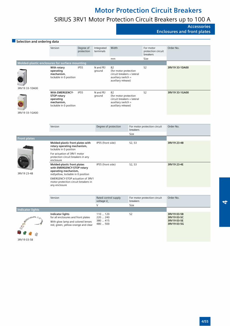
AccessoriesEnclosures and front plates
AccessoriesEnclosures and front plates
Selection and ordering data
Version Degree of protection
Integrated terminals
Width For motor protection circuit breakers
Order No.
mm Size
Molded-plastic enclosures for surface mounting
3RV19 33-1DA00
With rotary operating mechanism,lockable in 0 position
IP55 N and PE/ground
82 (for motor protection circuit breakers + lateral auxiliary switch + auxiliary release)
S2 3RV19 33-1DA00
3RV19 33-1GA00
With EMERGENCY-STOP rotary operating mechanism, lockable in 0 position
IP55 N and PE/ground
82 (for motor protection circuit breakers + lateral auxiliary switch + auxiliary release)
S2 3RV19 33-1GA00
Version Degree of protection For motor protection circuit breakers
Order No.
Size
Front plates
3RV19 23-4B
Molded-plastic front plates with rotary operating mechanism, lockable in 0 position
For actuation of 3RV1 motor protection circuit breakers in any enclosure
IP55 (front side) S2, S3 3RV19 23-4B
Molded-plastic front plates with EMERGENCY-STOP rotary operating mechanism, red/yellow, lockable in 0 position
EMERGENCY-STOP actuation of 3RV1 motor protection circuit breakers in any enclosure
IP55 (front side) S2, S3 3RV19 23-4E
Version Rated control supply voltage Us
For motor protection circuit breakers
Order No.
V Size
Indicator lights
3RV19 03-5B
Indicator lights for all enclosures and front plates
With glow lamp and colored lenses red, green, yellow-orange and clear
110 ... 120 220 ... 240 380 ... 415 480 ... 500
S2 3RV19 03-5B 3RV19 03-5C 3RV19 03-5E 3RV19 03-5G
Motor Protection Circuit BreakersSIRIUS 3RV1 Motor Protection Circuit Breakers up to 100 A
4/55
4

Overview
Features 3RU21 3RU11 3RB30/3RB31 3RB20/3RB21 3RB22/3RB23/3RB24 Benefits
General dataSizes S00, S0 S2, S3 S00, S0 S2 ... S12 S00 ... S12 • Are coordinated with the dimensions,
connections and technical characteristics of the other devices in the SIRIUS modular system (contactors, etc., ...)
• Permit the mounting of slim and compact load feeders in widths of 45 mm (S00), 45 mm (S0), 55 mm (S2), 70 mm (S3), 120 mm (S6) and 145 mm (S10/S12); this does not include the current measuring modules for the 3RB22 to 3RB24 evaluation modules sizes S00 to S3
• Simplify configuration
Seamless current range
0.11 ... 40 A 5.5 ... 100 A 0.1 ... 40 A 6 ... 630 A 0.3 ... 630 A (up to 820 A)1)
• Allows easy and consistent configuration with one series of overload relays (for small to large loads)
Protection functionsTripping in the event of overload
• Provides optimum inverse-time delayed protection of loads against excessive temperature rises due to overload
Tripping in the event of phase unbalance
() • Provides optimum inverse-time delayed protection of loads against excessive temperature rises due to phase unbalance
Tripping in the event of phase failure
• Minimizes heating of induction motors during phase failure
Protection of single-phase loads
— • Enables the protection of single-phase loads
Tripping in the event of overheating
by
integrated thermistor motor protection function
—2) —2) —2) —2) • Provides optimum temperature-dependent protection of loads against excessive temperature rises e.g. for stator-critical motors or in the event of insufficient coolant flow, contamination of the motor surface or for long starting or braking operations
• Eliminates the need for additional special equipment
• Saves space in the control cabinet
• Reduces wiring outlay and costs
Tripping in the event of a ground fault
by
internal ground-fault detection (activatable)
— — (only 3RB31)
(only 3RB21)
• Provides optimum protection of loads against high-resistance short-circuits or ground faults due to moisture, condensed water, damage to the insulation material, etc.
• Eliminates the need for additional special equipment
• Saves space in the control cabinet
• Reduces wiring outlay and costs
General dataGeneral data
Available
— Not available
1) Motor currents up to 820 A can be recorded and evaluated by a current measuring module, e.g. 3RB29 06-2BG1 (0.3 to 3 A), in combination with a 3UF18 68-3GA00 (820 A/1 A) series transformer.
2) The SIRIUS 3RN thermistor motor protection devices can be used to provide additional temperature-dependent protection.
Overload Relays
4/56
4
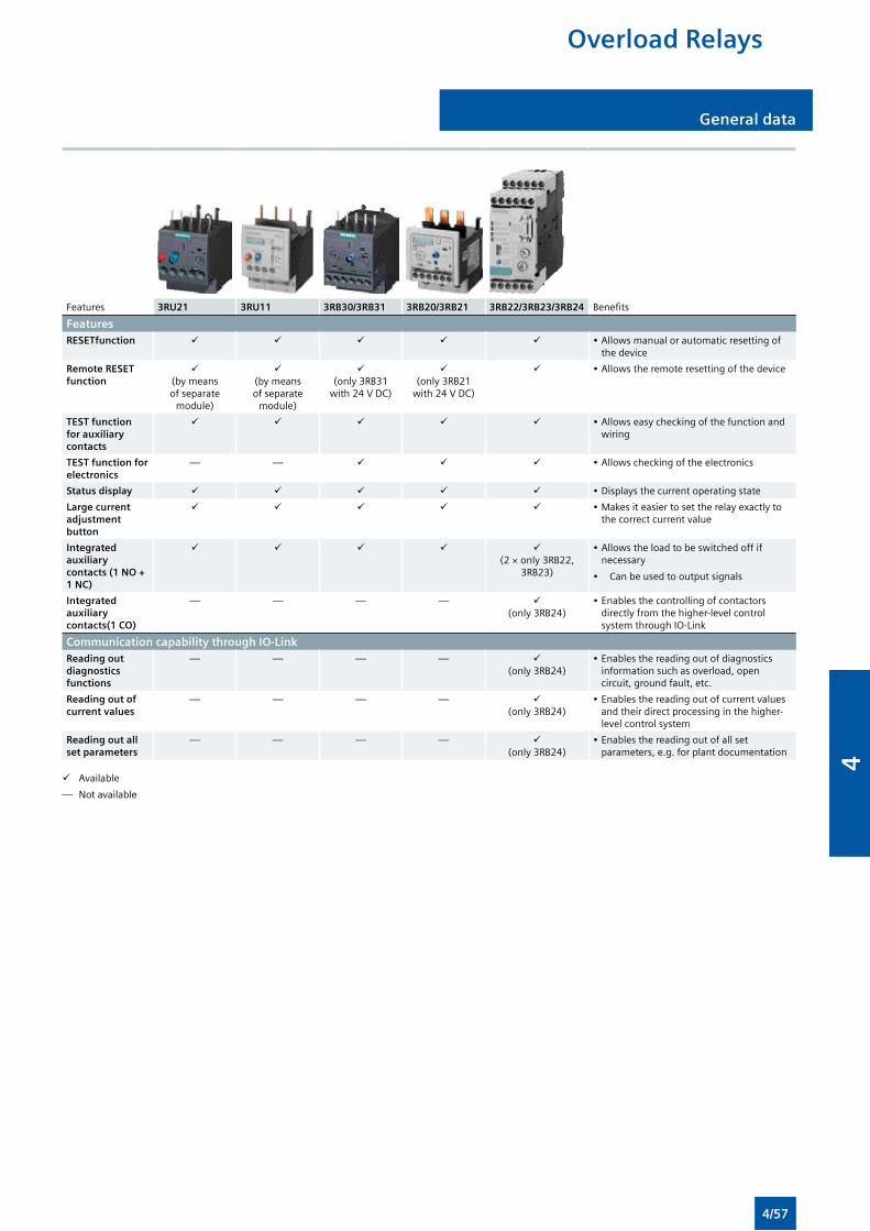
General data General data
Overload Relays
Features 3RU21 3RU11 3RB30/3RB31 3RB20/3RB21 3RB22/3RB23/3RB24 Benefits
FeaturesRESETfunction • Allows manual or automatic resetting of
the device
Remote RESET function
(by means of separate
module)
(by means of separate
module)
(only 3RB31
with 24 V DC)
(only 3RB21
with 24 V DC)
• Allows the remote resetting of the device
TEST function for auxiliary contacts
• Allows easy checking of the function and wiring
TEST function for electronics
— — • Allows checking of the electronics
Status display • Displays the current operating state
Large current adjustment button
• Makes it easier to set the relay exactly to the correct current value
Integrated auxiliary contacts (1 NO + 1 NC)
(2 × only 3RB22,
3RB23)
• Allows the load to be switched off if necessary
• Can be used to output signals
Integrated auxiliary contacts(1 CO)
— — — — (only 3RB24)
• Enables the controlling of contactors directly from the higher-level control system through IO-Link
Communication capability through IO-LinkReading out diagnostics functions
— — — — (only 3RB24)
• Enables the reading out of diagnostics information such as overload, open circuit, ground fault, etc.
Reading out of current values
— — — — (only 3RB24)
• Enables the reading out of current values and their direct processing in the higher-level control system
Reading out all set parameters
— — — — (only 3RB24)
• Enables the reading out of all set parameters, e.g. for plant documentation
Available
— Not available
4/57
4
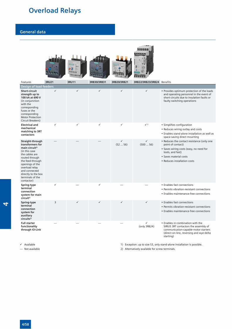
Overload Relays
General dataGeneral data
Features 3RU21 3RU11 3RB30/3RB31 3RB20/3RB21 3RB22/3RB23/3RB24 Benefits
Design of load feedersShort-circuit strength up to 100 kA at 690 V (in conjunction with the corresponding fuses or the corresponding Motor Protection Circuit Breakers)
• Provides optimum protection of the loads and operating personnel in the event of short-circuits due to insulation faults or faulty switching operations
Electrical and mechanical matching to 3RT contactors
1) • Simplifies configuration
• Reduces wiring outlay and costs
• Enables stand-alone installation as well as space-saving direct mounting
Straight-through transformers for main circuit2)
(in this case the cables are routed through the feed-through openings of the overload relay and connected directly to the box terminals of the contactor)
— — — (S2 ... S6)
(S00 ... S6)
• Reduces the contact resistance (only one point of contact)
• Saves wiring costs (easy, no need for tools, and fast)
• Saves material costs
• Reduces installation costs
Spring-type terminal connection system for main circuit2)
— — — • Enables fast connections
• Permits vibration-resistant connections
• Enables maintenance-free connections
Spring-type terminal connection system for auxiliary circuits2)
3 • Enables fast connections
• Permits vibration-resistant connections
• Enables maintenance-free connections
Full starter functionality through IO-Link
— — — — (only 3RB24)
• Enables in combination with the SIRIUS 3RT contactors the assembly of communication-capable motor starters (direct-on-line, reversing and wye-delta starting)
Available
— Not available
1) Exception: up to size S3, only stand-alone installation is possible.
2) Alternatively available for screw terminals.
4/58
4
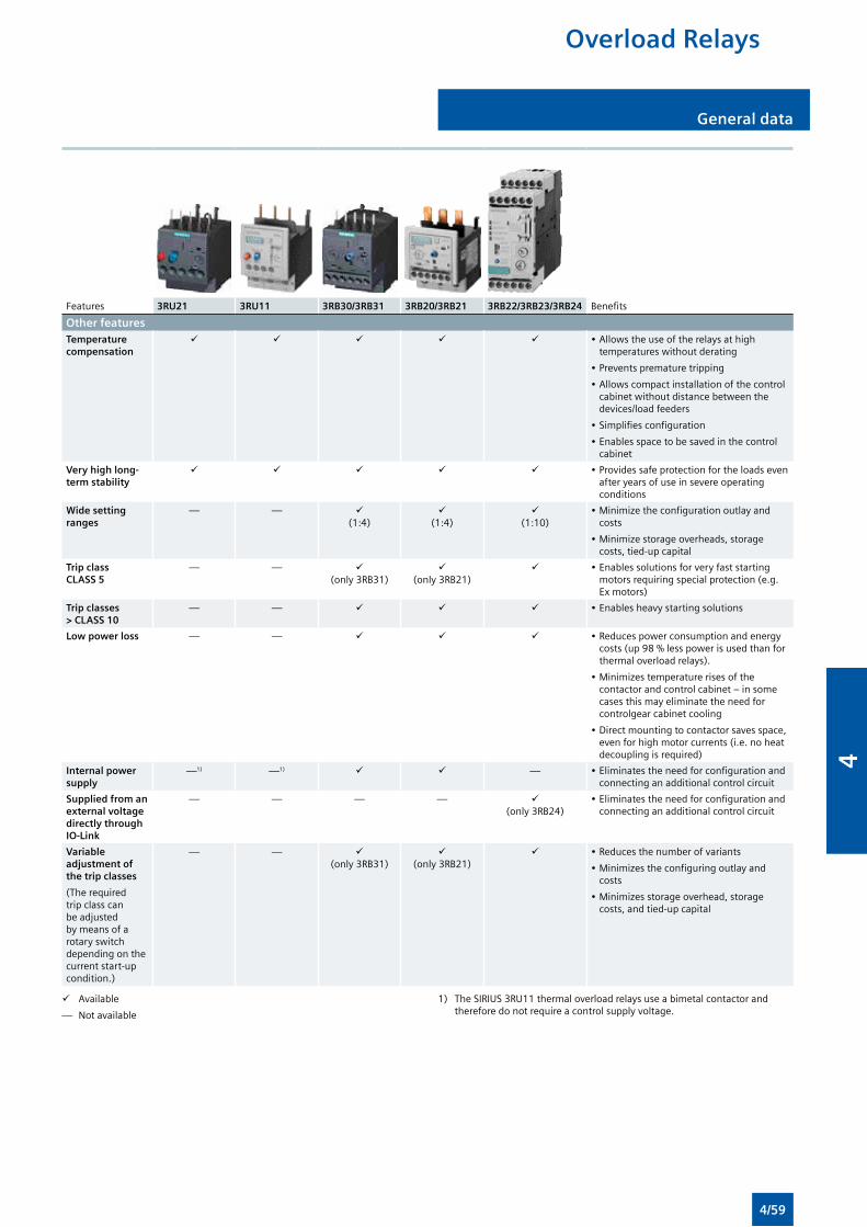
General data General data
Features 3RU21 3RU11 3RB30/3RB31 3RB20/3RB21 3RB22/3RB23/3RB24 Benefits
Other featuresTemperature compensation
• Allows the use of the relays at high temperatures without derating
• Prevents premature tripping
• Allows compact installation of the control cabinet without distance between the devices/load feeders
• Simplifies configuration
• Enables space to be saved in the control cabinet
Very high long-term stability
• Provides safe protection for the loads even after years of use in severe operating conditions
Wide setting ranges
— — (1:4)
(1:4)
(1:10)
• Minimize the configuration outlay and costs
• Minimize storage overheads, storage costs, tied-up capital
Trip class CLASS 5
— — (only 3RB31)
(only 3RB21)
• Enables solutions for very fast starting motors requiring special protection (e.g. Ex motors)
Trip classes > CLASS 10
— — • Enables heavy starting solutions
Low power loss — — • Reduces power consumption and energy costs (up 98 % less power is used than for thermal overload relays).
• Minimizes temperature rises of the contactor and control cabinet – in some cases this may eliminate the need for controlgear cabinet cooling
• Direct mounting to contactor saves space, even for high motor currents (i.e. no heat decoupling is required)
Internal power supply
—1) —1) — • Eliminates the need for configuration and connecting an additional control circuit
Supplied from an external voltage directly through IO-Link
— — — — (only 3RB24)
• Eliminates the need for configuration and connecting an additional control circuit
Variable adjustment of the trip classes
(The required trip class can be adjusted by means of a rotary switch depending on the current start-up condition.)
— — (only 3RB31)
(only 3RB21)
• Reduces the number of variants
• Minimizes the configuring outlay and costs
• Minimizes storage overhead, storage costs, and tied-up capital
Available
— Not available
1) The SIRIUS 3RU11 thermal overload relays use a bimetal contactor and therefore do not require a control supply voltage.
Overload Relays
4/59
4
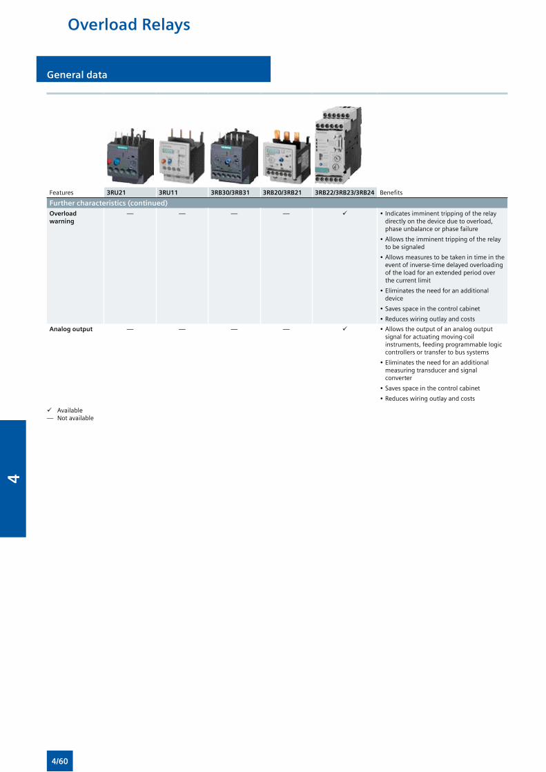
General dataGeneral data
Features 3RU21 3RU11 3RB30/3RB31 3RB20/3RB21 3RB22/3RB23/3RB24 Benefits
Further characteristics (continued)Overload warning
— — — — • Indicates imminent tripping of the relay directly on the device due to overload, phase unbalance or phase failure
• Allows the imminent tripping of the relay to be signaled
• Allows measures to be taken in time in the event of inverse-time delayed overloading of the load for an extended period over the current limit
• Eliminates the need for an additional device
• Saves space in the control cabinet
• Reduces wiring outlay and costs
Analog output — — — — • Allows the output of an analog output signal for actuating moving-coil instruments, feeding programmable logic controllers or transfer to bus systems
• Eliminates the need for an additional measuring transducer and signal converter
• Saves space in the control cabinet
• Reduces wiring outlay and costs
Available— Not available
Overload Relays
4/60
4
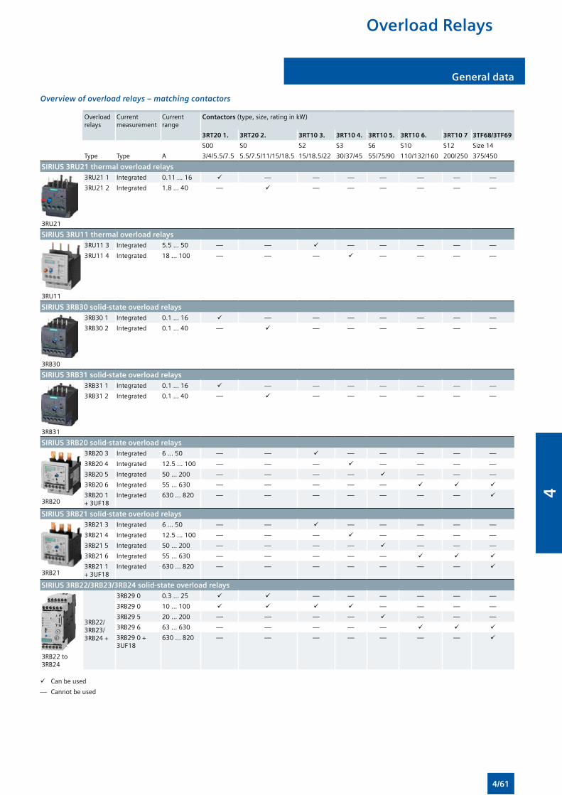
General data General data
Overview of overload relays – matching contactors
Overload relays
Current measurement
Current range
Contactors (type, size, rating in kW)
3RT20 1. 3RT20 2. 3RT10 3. 3RT10 4. 3RT10 5. 3RT10 6. 3RT10 7 3TF68/3TF69
S00 S0 S2 S3 S6 S10 S12 Size 14
Type Type A 3/4/5.5/7.5 5.5/7.5/11/15/18.5 15/18.5/22 30/37/45 55/75/90 110/132/160 200/250 375/450
SIRIUS 3RU21 thermal overload relays
3RU21
3RU21 1 Integrated 0.11 … 16 — — — — — — —
3RU21 2 Integrated 1.8 … 40 — — — — — — —
SIRIUS 3RU11 thermal overload relays
3RU11
3RU11 3 Integrated 5.5 … 50 — — — — — — —
3RU11 4 Integrated 18 … 100 — — — — — — —
SIRIUS 3RB30 solid-state overload relays
3RB30
3RB30 1 Integrated 0.1 … 16 — — — — — — —
3RB30 2 Integrated 0.1 … 40 — — — — — — —
SIRIUS 3RB31 solid-state overload relays
3RB31
3RB31 1 Integrated 0.1 … 16 — — — — — — —
3RB31 2 Integrated 0.1 … 40 — — — — — — —
SIRIUS 3RB20 solid-state overload relays
3RB20
3RB20 3 Integrated 6 … 50 — — — — — — —
3RB20 4 Integrated 12.5 … 100 — — — — — — —
3RB20 5 Integrated 50 ... 200 — — — — — — —
3RB20 6 Integrated 55 ... 630 — — — — —
3RB20 1 + 3UF18
Integrated 630 ... 820 — — — — — — —
SIRIUS 3RB21 solid-state overload relays
3RB21
3RB21 3 Integrated 6 … 50 — — — — — — —
3RB21 4 Integrated 12.5 … 100 — — — — — — —
3RB21 5 Integrated 50 ... 200 — — — — — — —
3RB21 6 Integrated 55 ... 630 — — — — —
3RB21 1 + 3UF18
Integrated 630 ... 820 — — — — — — —
SIRIUS 3RB22/3RB23/3RB24 solid-state overload relays
3RB22 to 3RB24
3RB22/ 3RB23/ 3RB24 +
3RB29 0 0.3 … 25 — — — — — —
3RB29 0 10 ... 100 — — — —
3RB29 5 20 … 200 — — — — — — —
3RB29 6 63 ... 630 — — — — —
3RB29 0 + 3UF18
630 ... 820 — — — — — — —
Can be used
— Cannot be used
Overload Relays
4/61
4

General dataGeneral data
Depending on the device version of the 3RU2 and 3RB3 overload relays, the terminals for screw, spring-type connection are configured for both the main and auxiliary circuit.
The 3RU11 thermal overload relays come with screw terminals.
The 3RB20 and 3RB21 solid-state overload relays are available with screw terminals (box terminals) or spring-type terminals on the auxiliary current side; the same applies for the evaluation modules of the 3RB22 to 3RB24 solid-state overload relays for high-feature applications.
Connection methods
Screw terminals
Spring-type terminals
The terminals are indicated in the corresponding tables by the symbols shown on orange backgrounds.
Overload Relays
4/62
4
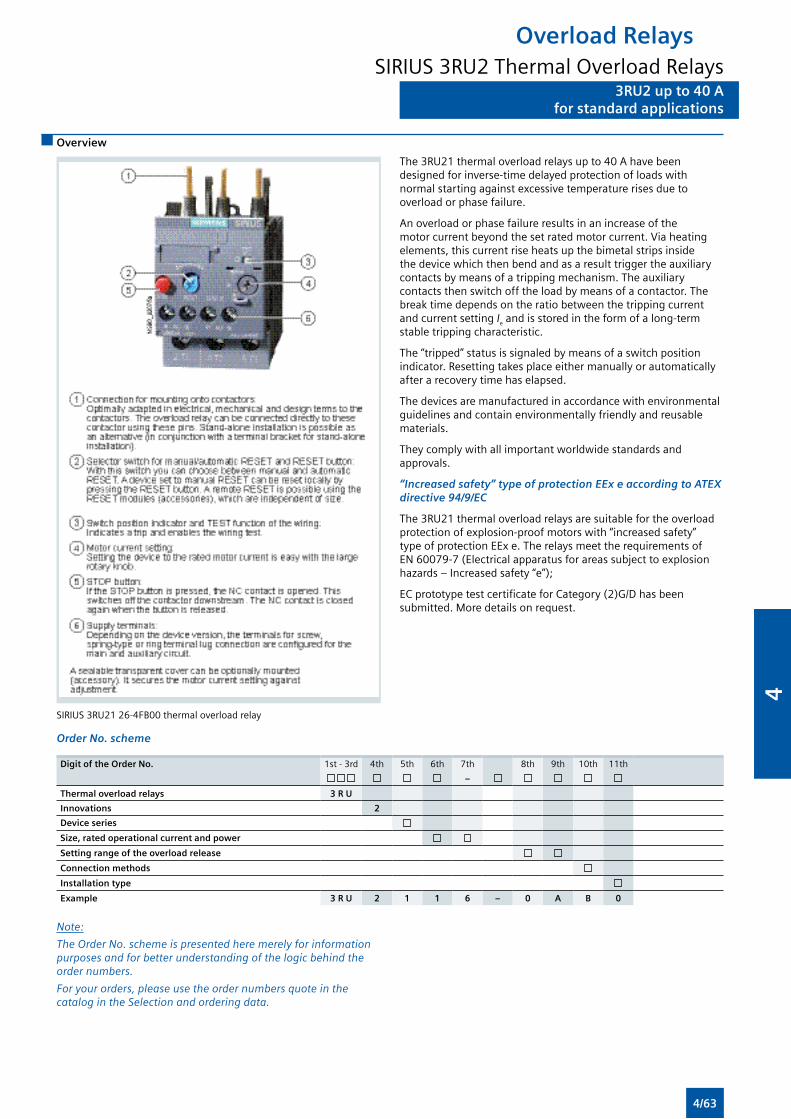
3RU2 up to 40 Afor standard applications
3RU2 up to 40 Afor standard applications
Overview
SIRIUS 3RU21 26-4FB00 thermal overload relay
The 3RU21 thermal overload relays up to 40 A have been designed for inverse-time delayed protection of loads with normal starting against excessive temperature rises due to overload or phase failure.
An overload or phase failure results in an increase of the motor current beyond the set rated motor current. Via heating elements, this current rise heats up the bimetal strips inside the device which then bend and as a result trigger the auxiliary contacts by means of a tripping mechanism. The auxiliary contacts then switch off the load by means of a contactor. The break time depends on the ratio between the tripping current and current setting Ie and is stored in the form of a long-term stable tripping characteristic.
The “tripped” status is signaled by means of a switch position indicator. Resetting takes place either manually or automatically after a recovery time has elapsed.
The devices are manufactured in accordance with environmental guidelines and contain environmentally friendly and reusable materials.
They comply with all important worldwide standards and approvals.
“Increased safety” type of protection EEx e according to ATEX directive 94/9/EC
The 3RU21 thermal overload relays are suitable for the overload protection of explosion-proof motors with “increased safety” type of protection EEx e. The relays meet the requirements of EN 60079-7 (Electrical apparatus for areas subject to explosion hazards – Increased safety “e”);
EC prototype test certificate for Category (2)G/D has been submitted. More details on request.
Order No. scheme
Digit of the Order No. 1st - 3rd 4th 5th 6th 7th 8th 9th 10th 11th
–
Thermal overload relays 3 R U
Innovations 2
Device series
Size, rated operational current and power
Setting range of the overload release
Connection methods
Installation type
Example 3 R U 2 1 1 6 – 0 A B 0
Note:
The Order No. scheme is presented here merely for information purposes and for better understanding of the logic behind the order numbers.
For your orders, please use the order numbers quote in the catalog in the Selection and ordering data.
Overload RelaysSIRIUS 3RU2 Thermal Overload Relays
4/63
4
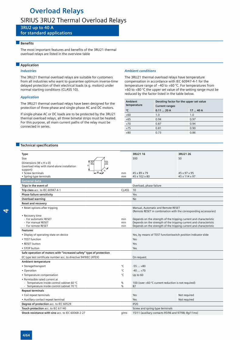
3RU2 up to 40 Afor standard applications
3RU2 up to 40 Afor standard applications
Benefits
The most important features and benefits of the 3RU21 thermal overload relays are listed in the overview table
Application
Industries
The 3RU21 thermal overload relays are suitable for customers from all industries who want to guarantee optimum inverse-time delayed protection of their electrical loads (e.g. motors) under normal starting conditions (CLASS 10).
Application
The 3RU21 thermal overload relays have been designed for the protection of three-phase and single-phase AC and DC motors.
If single-phase AC or DC loads are to be protected by the 3RU21 thermal overload relays, all three bimetal strips must be heated. For this purpose, all main current paths of the relay must be connected in series.
Ambient conditions
The 3RU21 thermal overload relays have temperature compensation in accordance with IEC 60947-4-1 for the temperature range of –40 to +60 °C. For temperatures from +60 to +80 °C the upper set value of the setting range must be reduced by the factor listed in the table below.
Ambient temperature
Derating factor for the upper set value
Current ranges
°C 0.11 ... 20 A 17 ... 40 A
+60 1.0 1.0
+65 0.94 0.97
+70 0.87 0.94
+75 0.81 0.90
+80 0.73 0.86
Technical specifications
Type 3RU21 16 3RU21 26
Size S00 S0
Dimensions (W x H x D)(overload relay with stand-alone installation support)• Screw terminals• Spring-type terminals
mmmm
45 x 89 x 7945 x 102 x 80
45 x 97 x 9545 x 114 x 97
General data Trips in the event of Overload, phase failure
Trip class acc. to IEC 60947-4-1 CLASS 10
Phase failure sensitivity Yes
Overload warning No
Reset and recovery
• Reset options after tripping Manual, Automatic and Remote RESET (Remote RESET in combination with the corresponding accessories)
• Recovery time - For automatic RESET - For manual RESET - For remote RESET
minminmin
Depends on the strength of the tripping current and characteristicDepends on the strength of the tripping current and characteristicDepends on the strength of the tripping current and characteristic
Features
• Display of operating state on device Yes, by means of TEST function/switch position indicator slide
• TEST function Yes
• RESET button Yes
• STOP button Yes
Safe operation of motors with “increased safety” type of protection
EC type test certificate number acc. to directive 94/9/EC (ATEX) On request
Ambient temperature
• Storage/transport °C -55 ... +80
• Operation °C -40 ... +70
• Temperature compensation °C Up to 60
• Permissible rated current at - Temperature inside control cabinet 60 °C - Temperature inside control cabinet 70 °C
%%
100 (over +60 °C current reduction is not required)87
Repeat terminals
• Coil repeat terminals Yes Not required
• Auxiliary contact repeat terminal Yes Not required
Degree of protection acc. to IEC 60529 IP20
Touch protection acc. to IEC 61140 Screw and spring-type terminals
Shock resistance with sine acc. to IEC 60068-2-27 g/ms 15/11 (auxiliary contacts 95/96 and 97/98; 8g/11ms)
Overload RelaysSIRIUS 3RU2 Thermal Overload Relays
4/64
4
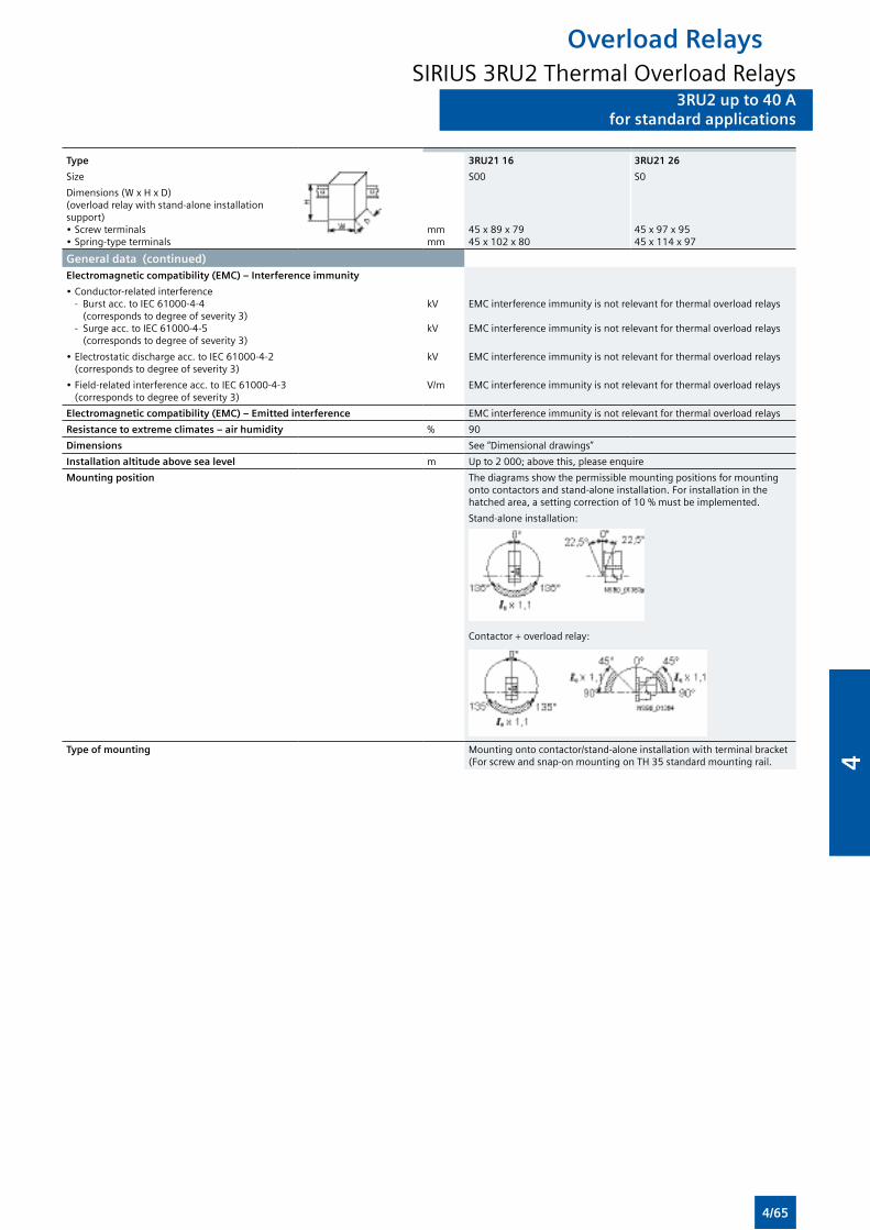
3RU2 up to 40 Afor standard applications
Type 3RU21 16 3RU21 26
Size S00 S0
Dimensions (W x H x D)(overload relay with stand-alone installation support)• Screw terminals• Spring-type terminals
mmmm
45 x 89 x 7945 x 102 x 80
45 x 97 x 9545 x 114 x 97
General data (continued)Electromagnetic compatibility (EMC) – Interference immunity
• Conductor-related interference - Burst acc. to IEC 61000-4-4
(corresponds to degree of severity 3) - Surge acc. to IEC 61000-4-5
(corresponds to degree of severity 3)
kV
kV
EMC interference immunity is not relevant for thermal overload relays
EMC interference immunity is not relevant for thermal overload relays
• Electrostatic discharge acc. to IEC 61000-4-2 (corresponds to degree of severity 3)
kV EMC interference immunity is not relevant for thermal overload relays
• Field-related interference acc. to IEC 61000-4-3 (corresponds to degree of severity 3)
V/m EMC interference immunity is not relevant for thermal overload relays
Electromagnetic compatibility (EMC) – Emitted interference EMC interference immunity is not relevant for thermal overload relays
Resistance to extreme climates – air humidity % 90
Dimensions See “Dimensional drawings”
Installation altitude above sea level m Up to 2 000; above this, please enquire
Mounting position The diagrams show the permissible mounting positions for mounting onto contactors and stand-alone installation. For installation in the hatched area, a setting correction of 10 % must be implemented.
Stand-alone installation:
Contactor + overload relay:
Type of mounting Mounting onto contactor/stand-alone installation with terminal bracket (For screw and snap-on mounting on TH 35 standard mounting rail.
Overload RelaysSIRIUS 3RU2 Thermal Overload Relays
3RU2 up to 40 Afor standard applications
4/65
4
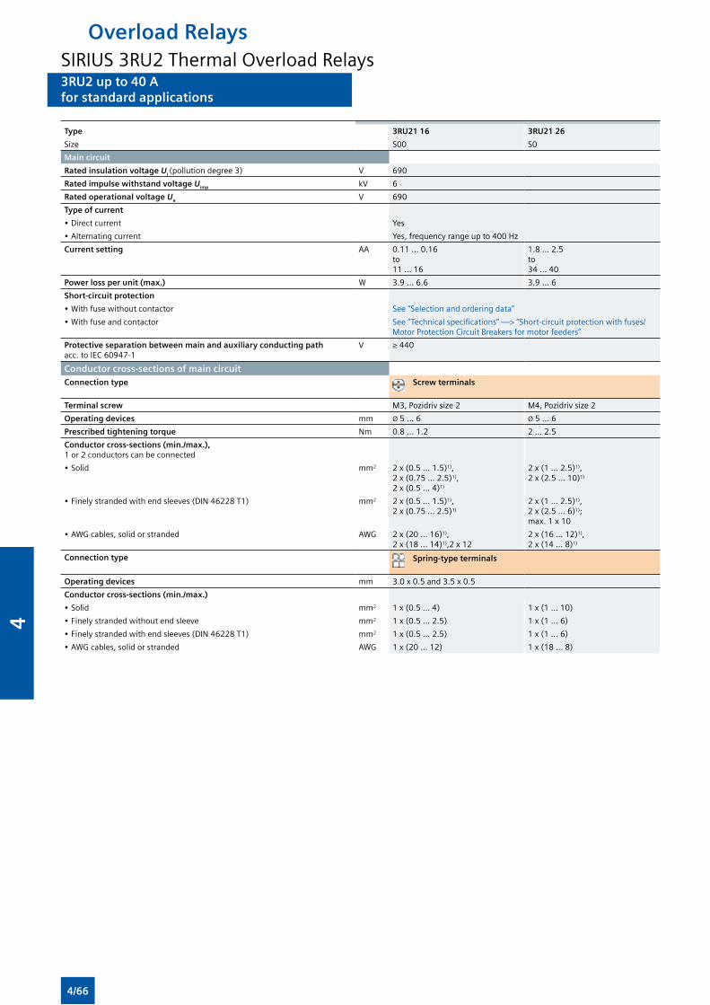
3RU2 up to 40 Afor standard applications
Type 3RU21 16 3RU21 26
Size S00 S0
Main circuit
Rated insulation voltage Ui (pollution degree 3) V 690
Rated impulse withstand voltage Uimp kV 6
Rated operational voltage Ue V 690
Type of current
• Direct current Yes
• Alternating current Yes, frequency range up to 400 Hz
Current setting AA 0.11 ... 0.16 to 11 ... 16
1.8 ... 2.5 to 34 ... 40
Power loss per unit (max.) W 3.9 ... 6.6 3.9 ... 6
Short-circuit protection
• With fuse without contactor See “Selection and ordering data”
• With fuse and contactor See “Technical specifications” —> “Short-circuit protection with fuses/Motor Protection Circuit Breakers for motor feeders”
Protective separation between main and auxiliary conducting path acc. to IEC 60947-1
V ≥ 440
Conductor cross-sections of main circuitConnection type Screw terminals
Terminal screw M3, Pozidriv size 2 M4, Pozidriv size 2
Operating devices mm Ø 5 ... 6 Ø 5 ... 6
Prescribed tightening torque Nm 0.8 ... 1.2 2 ... 2.5
Conductor cross-sections (min./max.), 1 or 2 conductors can be connected
• Solid mm2 2 x (0.5 ... 1.5)1), 2 x (0.75 ... 2.5)1), 2 x (0.5 ... 4)1)
2 x (1 ... 2.5)1), 2 x (2.5 ... 10)1)
• Finely stranded with end sleeves (DIN 46228 T1) mm2 2 x (0.5 ... 1.5)1), 2 x (0.75 ... 2.5)1)
2 x (1 ... 2.5)1), 2 x (2.5 ... 6)1); max. 1 x 10
• AWG cables, solid or stranded AWG 2 x (20 ... 16)1), 2 x (18 ... 14)1),2 x 12
2 x (16 ... 12)1), 2 x (14 ... 8)1)
Connection type Spring-type terminals
Operating devices mm 3.0 x 0.5 and 3.5 x 0.5
Conductor cross-sections (min./max.)
• Solid mm2 1 x (0.5 ... 4) 1 x (1 ... 10)
• Finely stranded without end sleeve mm2 1 x (0.5 ... 2.5) 1 x (1 ... 6)
• Finely stranded with end sleeves (DIN 46228 T1) mm2 1 x (0.5 ... 2.5) 1 x (1 ... 6)
• AWG cables, solid or stranded AWG 1 x (20 ... 12) 1 x (18 ... 8)
Overload RelaysSIRIUS 3RU2 Thermal Overload Relays3RU2 up to 40 Afor standard applications
4/66
4
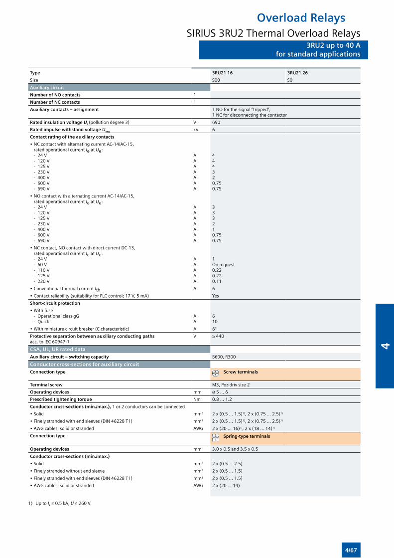
3RU2 up to 40 Afor standard applications
Type 3RU21 16 3RU21 26
Size S00 S0
Auxiliary circuit
Number of NO contacts 1
Number of NC contacts 1
Auxiliary contacts – assignment 1 NO for the signal “tripped”; 1 NC for disconnecting the contactor
Rated insulation voltage Ui (pollution degree 3) V 690
Rated impulse withstand voltage Uimp kV 6
Contact rating of the auxiliary contacts
• NC contact with alternating current AC-14/AC-15, rated operational current Ie at Ue:
- 24 V - 120 V - 125 V - 230 V - 400 V - 600 V - 690 V
AAAAAAA
444320.750.75
• NO contact with alternating current AC-14/AC-15, rated operational current Ie at Ue:
- 24 V - 120 V - 125 V - 230 V - 400 V - 600 V - 690 V
AAAAAAA
333210.750.75
• NC contact, NO contact with direct current DC-13, rated operational current Ie at Ue:
- 24 V - 60 V - 110 V - 125 V - 220 V
AAAAA
1On request0.220.220.11
• Conventional thermal current Ith A 6
• Contact reliability (suitability for PLC control; 17 V, 5 mA) Yes
Short-circuit protection
• With fuse - Operational class gG - Quick
AA
610
• With miniature circuit breaker (C characteristic) A 61)
Protective separation between auxiliary conducting paths acc. to IEC 60947-1
V ≥ 440
CSA, UL, UR rated dataAuxiliary circuit – switching capacity B600, R300
Conductor cross-sections for auxiliary circuitConnection type Screw terminals
Terminal screw M3, Pozidriv size 2
Operating devices mm Ø 5 ... 6
Prescribed tightening torque Nm 0.8 ... 1.2
Conductor cross-sections (min./max.), 1 or 2 conductors can be connected
• Solid mm2 2 x (0.5 ... 1.5)1), 2 x (0.75 ... 2.5)1)
• Finely stranded with end sleeves (DIN 46228 T1) mm2 2 x (0.5 ... 1.5)1), 2 x (0.75 ... 2.5)1)
• AWG cables, solid or stranded AWG 2 x (20 ... 16)1); 2 x (18 ... 14)1)
Connection type Spring-type terminals
Operating devices mm 3.0 x 0.5 and 3.5 x 0.5
Conductor cross-sections (min./max.)
• Solid mm2 2 x (0.5 ... 2.5)
• Finely stranded without end sleeve mm2 2 x (0.5 ... 1.5)
• Finely stranded with end sleeves (DIN 46228 T1) mm2 2 x (0.5 ... 1.5)
• AWG cables, solid or stranded AWG 2 x (20 ... 14)
1) Up to Ik ≤ 0.5 kA; U ≤ 260 V.
Overload RelaysSIRIUS 3RU2 Thermal Overload Relays
3RU2 up to 40 Afor standard applications
4/67
4
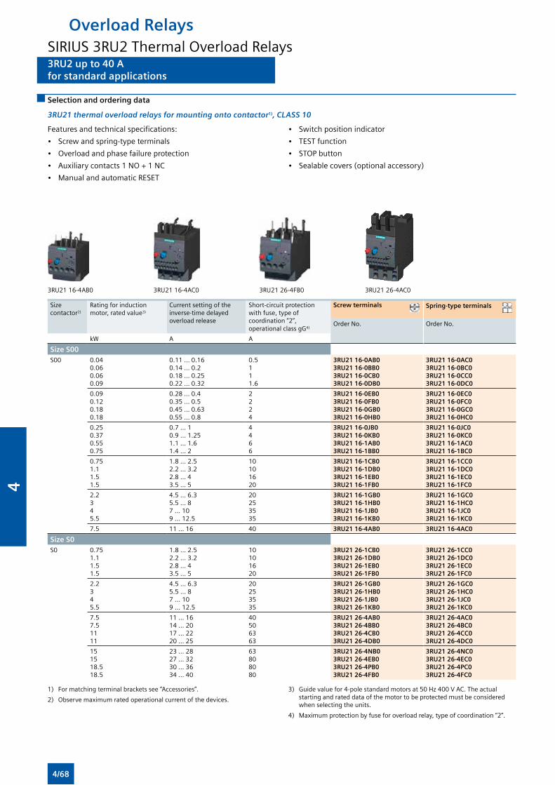
3RU2 up to 40 Afor standard applications
3RU2 up to 40 Afor standard applications
Selection and ordering data
3RU21 thermal overload relays for mounting onto contactor1), CLASS 10
Features and technical specifications:
• Screw and spring-type terminals
• Overload and phase failure protection
• Auxiliary contacts 1 NO + 1 NC
• Manual and automatic RESET
• Switch position indicator
• TEST function
• STOP button
• Sealable covers (optional accessory)
3RU21 16-4AB0 3RU21 16-4AC0 3RU21 26-4FB0 3RU21 26-4AC0
Size contactor2)
Rating for induction motor, rated value3)
Current setting of the inverse-time delayed overload release
Short-circuit protection with fuse, type of coordination “2”, operational class gG4)
Screw terminals Spring-type terminals
Order No. Order No.
kW A A
Size S00S00 0.04
0.060.060.09
0.11 ... 0.160.14 ... 0.20.18 ... 0.250.22 ... 0.32
0.511 1.6
3RU21 16-0AB03RU21 16-0BB03RU21 16-0CB03RU21 16-0DB0
3RU21 16-0AC03RU21 16-0BC03RU21 16-0CC03RU21 16-0DC0
0.090.120.180.18
0.28 ... 0.40.35 ... 0.50.45 ... 0.630.55 ... 0.8
22 24
3RU21 16-0EB03RU21 16-0FB03RU21 16-0GB03RU21 16-0HB0
3RU21 16-0EC03RU21 16-0FC03RU21 16-0GC03RU21 16-0HC0
0.250.370.550.75
0.7 ... 10.9 ... 1.251.1 ... 1.61.4 ... 2
4 466
3RU21 16-0JB03RU21 16-0KB03RU21 16-1AB03RU21 16-1BB0
3RU21 16-0JC03RU21 16-0KC03RU21 16-1AC03RU21 16-1BC0
0.751.11.51.5
1.8 ... 2.52.2 ... 3.22.8 ... 43.5 ... 5
1010 1620
3RU21 16-1CB03RU21 16-1DB03RU21 16-1EB03RU21 16-1FB0
3RU21 16-1CC03RU21 16-1DC03RU21 16-1EC03RU21 16-1FC0
2.2345.5
4.5 ... 6.35.5 ... 87 ... 109 ... 12.5
20 253535
3RU21 16-1GB03RU21 16-1HB03RU21 16-1JB03RU21 16-1KB0
3RU21 16-1GC03RU21 16-1HC03RU21 16-1JC03RU21 16-1KC0
7.5 11 ... 16 40 3RU21 16-4AB0 3RU21 16-4AC0
Size S0S0 0.75
1.11.51.5
1.8 ... 2.52.2 ... 3.22.8 ... 43.5 ... 5
1010 1620
3RU21 26-1CB03RU21 26-1DB03RU21 26-1EB03RU21 26-1FB0
3RU21 26-1CC03RU21 26-1DC03RU21 26-1EC03RU21 26-1FC0
2.2345.5
4.5 ... 6.35.5 ... 87 ... 109 ... 12.5
20 253535
3RU21 26-1GB03RU21 26-1HB03RU21 26-1JB03RU21 26-1KB0
3RU21 26-1GC03RU21 26-1HC03RU21 26-1JC03RU21 26-1KC0
7.57.51111
11 ... 1614 ... 2017 ... 2220 ... 25
40506363
3RU21 26-4AB03RU21 26-4BB03RU21 26-4CB03RU21 26-4DB0
3RU21 26-4AC03RU21 26-4BC03RU21 26-4CC03RU21 26-4DC0
151518.518.5
23 ... 2827 ... 3230 ... 3634 ... 40
63808080
3RU21 26-4NB03RU21 26-4EB03RU21 26-4PB03RU21 26-4FB0
3RU21 26-4NC03RU21 26-4EC03RU21 26-4PC03RU21 26-4FC0
1) For matching terminal brackets see “Accessories”.
2) Observe maximum rated operational current of the devices.
3) Guide value for 4-pole standard motors at 50 Hz 400 V AC. The actual starting and rated data of the motor to be protected must be considered when selecting the units.
4) Maximum protection by fuse for overload relay, type of coordination “2”.
Overload RelaysSIRIUS 3RU2 Thermal Overload Relays
4/68
4
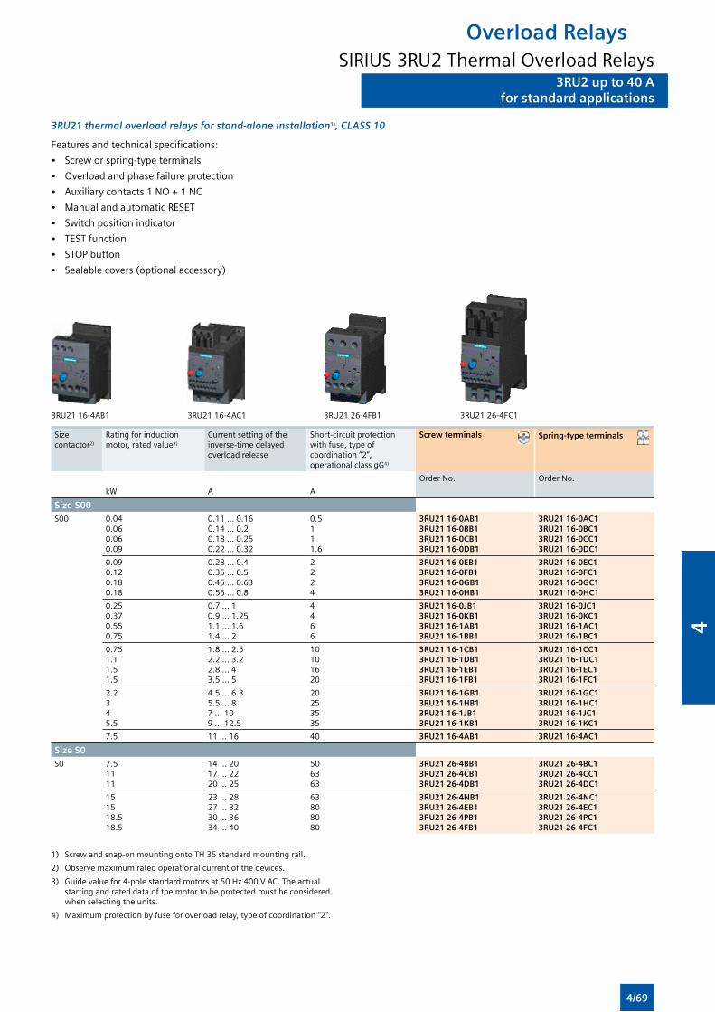
3RU2 up to 40 Afor standard applications
3RU2 up to 40 Afor standard applications
3RU21 thermal overload relays for stand-alone installation1), CLASS 10
Features and technical specifications:
• Screw or spring-type terminals
• Overload and phase failure protection
• Auxiliary contacts 1 NO + 1 NC
• Manual and automatic RESET
• Switch position indicator
• TEST function
• STOP button
• Sealable covers (optional accessory)
3RU21 16-4AB1 3RU21 16-4AC1 3RU21 26-4FB1 3RU21 26-4FC1
Size contactor2)
Rating for induction motor, rated value3)
Current setting of the inverse-time delayed overload release
Short-circuit protection with fuse, type of coordination “2”, operational class gG4)
Screw terminals Spring-type terminals
Order No. Order No.
kW A A
Size S00S00 0.04
0.060.060.09
0.11 ... 0.160.14 ... 0.20.18 ... 0.250.22 ... 0.32
0.5111.6
3RU21 16-0AB13RU21 16-0BB13RU21 16-0CB13RU21 16-0DB1
3RU21 16-0AC13RU21 16-0BC13RU21 16-0CC13RU21 16-0DC1
0.090.120.180.18
0.28 ... 0.40.35 ... 0.50.45 ... 0.630.55 ... 0.8
2224
3RU21 16-0EB13RU21 16-0FB13RU21 16-0GB13RU21 16-0HB1
3RU21 16-0EC13RU21 16-0FC13RU21 16-0GC13RU21 16-0HC1
0.250.370.550.75
0.7 ... 10.9 ... 1.251.1 ... 1.61.4 ... 2
4466
3RU21 16-0JB13RU21 16-0KB13RU21 16-1AB13RU21 16-1BB1
3RU21 16-0JC13RU21 16-0KC13RU21 16-1AC13RU21 16-1BC1
0.751.11.51.5
1.8 ... 2.52.2 ... 3.22.8 ... 43.5 ... 5
10101620
3RU21 16-1CB13RU21 16-1DB13RU21 16-1EB13RU21 16-1FB1
3RU21 16-1CC13RU21 16-1DC13RU21 16-1EC13RU21 16-1FC1
2.2345.5
4.5 ... 6.35.5 ... 87 ... 109 ... 12.5
20253535
3RU21 16-1GB13RU21 16-1HB13RU21 16-1JB13RU21 16-1KB1
3RU21 16-1GC13RU21 16-1HC13RU21 16-1JC13RU21 16-1KC1
7.5 11 ... 16 40 3RU21 16-4AB1 3RU21 16-4AC1
Size S0S0 7.5
1111
14 ... 2017 ... 2220 ... 25
506363
3RU21 26-4BB13RU21 26-4CB13RU21 26-4DB1
3RU21 26-4BC13RU21 26-4CC13RU21 26-4DC1
151518.518.5
23 ... 2827 ... 3230 ... 3634 ... 40
63808080
3RU21 26-4NB13RU21 26-4EB13RU21 26-4PB13RU21 26-4FB1
3RU21 26-4NC13RU21 26-4EC13RU21 26-4PC13RU21 26-4FC1
1) Screw and snap-on mounting onto TH 35 standard mounting rail.
2) Observe maximum rated operational current of the devices.
3) Guide value for 4-pole standard motors at 50 Hz 400 V AC. The actual starting and rated data of the motor to be protected must be considered when selecting the units.
4) Maximum protection by fuse for overload relay, type of coordination “2”.
Overload RelaysSIRIUS 3RU2 Thermal Overload Relays
4/69
4
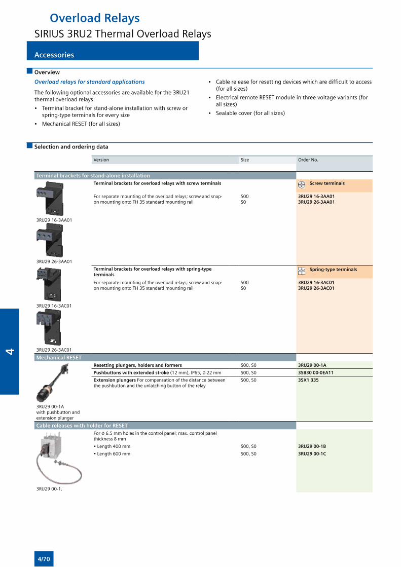
Accessories Accessories
Overview
Overload relays for standard applications
The following optional accessories are available for the 3RU21 thermal overload relays:
• Terminal bracket for stand-alone installation with screw or spring-type terminals for every size
• Mechanical RESET (for all sizes)
• Cable release for resetting devices which are difficult to access (for all sizes)
• Electrical remote RESET module in three voltage variants (for all sizes)
• Sealable cover (for all sizes)
Selection and ordering data
Version Size Order No.
Terminal brackets for stand-alone installation
3RU29 16-3AA01
3RU29 26-3AA01
Terminal brackets for overload relays with screw terminals Screw terminals
For separate mounting of the overload relays; screw and snap-on mounting onto TH 35 standard mounting rail
S00S0
3RU29 16-3AA013RU29 26-3AA01
3RU29 16-3AC01
3RU29 26-3AC01
Terminal brackets for overload relays with spring-type terminals
Spring-type terminals
For separate mounting of the overload relays; screw and snap-on mounting onto TH 35 standard mounting rail
S00S0
3RU29 16-3AC013RU29 26-3AC01
Mechanical RESET
3RU29 00-1A with pushbutton and extension plunger
Resetting plungers, holders and formers S00, S0 3RU29 00-1A
Pushbuttons with extended stroke (12 mm), IP65, Ø 22 mm S00, S0 3SB30 00-0EA11
Extension plungers For compensation of the distance between the pushbutton and the unlatching button of the relay
S00, S0 3SX1 335
Cable releases with holder for RESET
3RU29 00-1.
For Ø 6.5 mm holes in the control panel; max. control panel thickness 8 mm
• Length 400 mm S00, S0 3RU29 00-1B
• Length 600 mm S00, S0 3RU29 00-1C
Overload RelaysSIRIUS 3RU2 Thermal Overload Relays
4/70
4
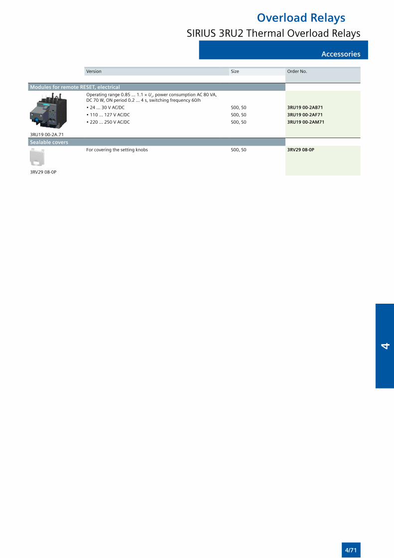
AccessoriesAccessories
Version Size Order No.
Modules for remote RESET, electrical
3RU19 00-2A.71
Operating range 0.85 ... 1.1 × Us, power consumption AC 80 VA, DC 70 W, ON period 0.2 ... 4 s, switching frequency 60/h
• 24 ... 30 V AC/DC S00, S0 3RU19 00-2AB71
• 110 ... 127 V AC/DC S00, S0 3RU19 00-2AF71
• 220 ... 250 V AC/DC S00, S0 3RU19 00-2AM71
Sealable covers
3RV29 08-0P
For covering the setting knobs S00, S0 3RV29 08-0P
Overload RelaysSIRIUS 3RU2 Thermal Overload Relays
4/71
4
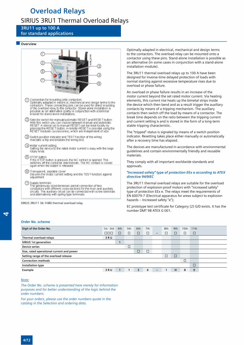
Overview
3RU11 up to 100 Afor standard applications
Overload RelaysSIRIUS 3RU1 Thermal Overload Relays3RU11 up to 100 Afor standard applications
Optimally adapted in electrical, mechanical and design terms to the contactors. The overload relay can be mounted onto a contactor using these pins. Stand-alone installation is possible as an alternative (in some cases in conjunction with a stand-alone installation module).
The 3RU11 thermal overload relays up to 100 A have been designed for inverse-time delayed protection of loads with normal starting against excessive temperature rises due to overload or phase failure.
An overload or phase failure results in an increase of the motor current beyond the set rated motor current. Via heating elements, this current rise heats up the bimetal strips inside the device which then bend and as a result trigger the auxiliary contacts by means of a tripping mechanism. The auxiliary contacts then switch off the load by means of a contactor. The break time depends on the ratio between the tripping current and current setting Ie and is stored in the form of a long-term stable tripping characteristic.
The "tripped" status is signaled by means of a switch position indicator. Resetting takes place either manually or automatically after a recovery time has elapsed.
The devices are manufactured in accordance with environmental guidelines and contain environmentally friendly and reusable materials.
They comply with all important worldwide standards and approvals.
"Increased safety" type of protection EEx e according to ATEX directive 94/9/EC
The 3RU11 thermal overload relays are suitable for the overload protection of explosion-proof motors with "increased safety" type of protection EEx e. The relays meet the requirements of EN 60079-7 (Electrical apparatus for areas subject to explosion hazards – Increased safety "e");
EC prototype test certificate for Category (2) G/D exists. It has the number DMT 98 ATEX G 001.
SIRIUS 3RU11 36-1HB0 thermal overload relay
Order No. scheme
Digit of the Order No. 1st - 3rd 4th 5th 6th 7th 8th 9th 10th 11th
–
Thermal overload relays 3 R U
SIRIUS 1st generation 1
Device series
Size, rated operational current and power
Setting range of the overload release
Connection methods
Installation type
Example 3 R U 1 1 3 6 – 1 H B 0
Note:
The Order No. scheme is presented here merely for information purposes and for better understanding of the logic behind the order numbers.
For your orders, please use the order numbers quote in the catalog in the Selection and ordering data.
4/72
4
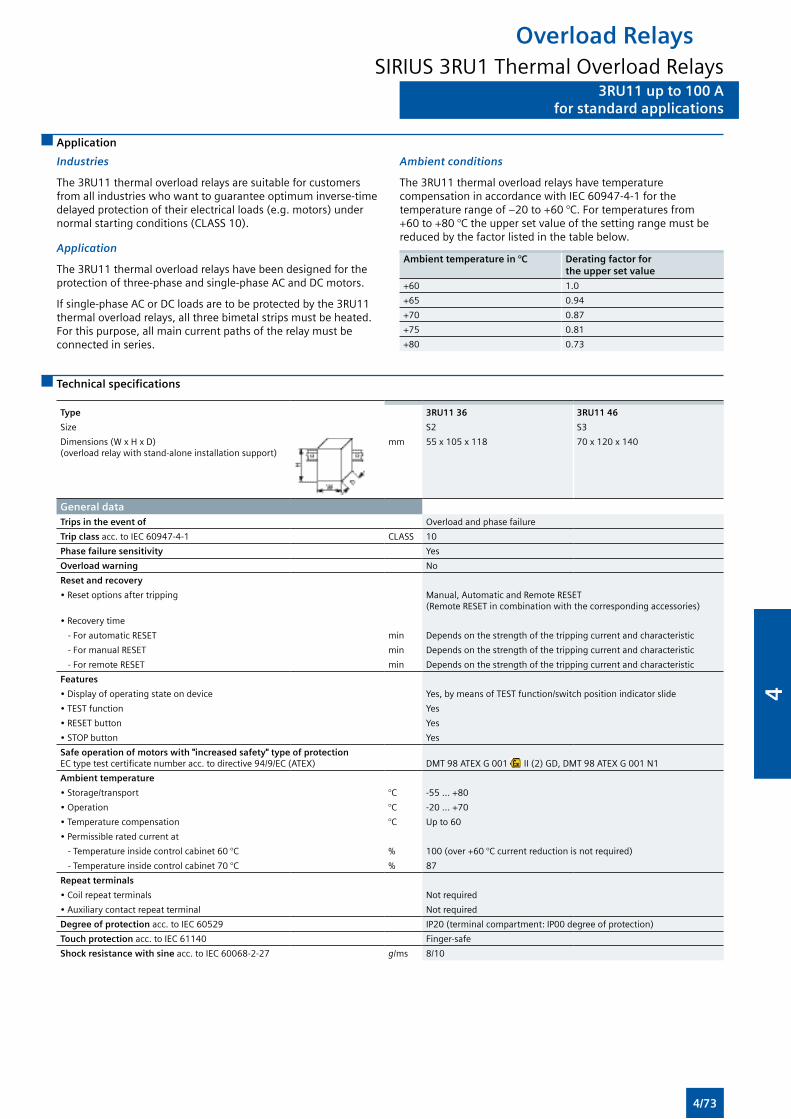
3RU11 up to 100 Afor standard applications
Overload RelaysSIRIUS 3RU1 Thermal Overload Relays
3RU11 up to 100 Afor standard applications
Application
Industries
The 3RU11 thermal overload relays are suitable for customers from all industries who want to guarantee optimum inverse-time delayed protection of their electrical loads (e.g. motors) under normal starting conditions (CLASS 10).
Application
The 3RU11 thermal overload relays have been designed for the protection of three-phase and single-phase AC and DC motors.
If single-phase AC or DC loads are to be protected by the 3RU11 thermal overload relays, all three bimetal strips must be heated. For this purpose, all main current paths of the relay must be connected in series.
Ambient conditions
The 3RU11 thermal overload relays have temperature compensation in accordance with IEC 60947-4-1 for the temperature range of –20 to +60 °C. For temperatures from +60 to +80 °C the upper set value of the setting range must be reduced by the factor listed in the table below.
Ambient temperature in °C Derating factor for the upper set value
+60 1.0
+65 0.94
+70 0.87
+75 0.81
+80 0.73
Technical specifications
Type 3RU11 36 3RU11 46
Size S2 S3
Dimensions (W x H x D) (overload relay with stand-alone installation support)
mm 55 x 105 x 118 70 x 120 x 140
General dataTrips in the event of Overload and phase failure
Trip class acc. to IEC 60947-4-1 CLASS 10
Phase failure sensitivity Yes
Overload warning No
Reset and recovery
• Reset options after tripping Manual, Automatic and Remote RESET (Remote RESET in combination with the corresponding accessories)
• Recovery time
- For automatic RESET min Depends on the strength of the tripping current and characteristic
- For manual RESET min Depends on the strength of the tripping current and characteristic
- For remote RESET min Depends on the strength of the tripping current and characteristic
Features
• Display of operating state on device Yes, by means of TEST function/switch position indicator slide
• TEST function Yes
• RESET button Yes
• STOP button Yes
Safe operation of motors with "increased safety" type of protection EC type test certificate number acc. to directive 94/9/EC (ATEX) DMT 98 ATEX G 001 II (2) GD, DMT 98 ATEX G 001 N1
Ambient temperature
• Storage/transport °C -55 ... +80
• Operation °C -20 ... +70
• Temperature compensation °C Up to 60
• Permissible rated current at
- Temperature inside control cabinet 60 °C % 100 (over +60 °C current reduction is not required)
- Temperature inside control cabinet 70 °C % 87
Repeat terminals
• Coil repeat terminals Not required
• Auxiliary contact repeat terminal Not required
Degree of protection acc. to IEC 60529 IP20 (terminal compartment: IP00 degree of protection)
Touch protection acc. to IEC 61140 Finger-safe
Shock resistance with sine acc. to IEC 60068-2-27 g/ms 8/10
4/73
4
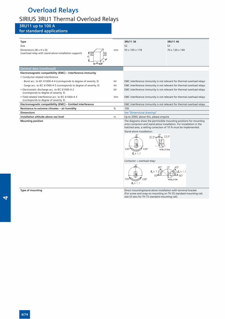
3RU11 up to 100 Afor standard applications
Overload RelaysSIRIUS 3RU1 Thermal Overload Relays3RU11 up to 100 Afor standard applications
Type 3RU11 36 3RU11 46
Size S2 S3
Dimensions (W x H x D) (overload relay with stand-alone installation support)
mm 55 x 105 x 118 70 x 120 x 140
General data (continued)Electromagnetic compatibility (EMC) – Interference immunity
• Conductor-related interference
- Burst acc. to IEC 61000-4-4 (corresponds to degree of severity 3) kV EMC interference immunity is not relevant for thermal overload relays
- Surge acc. to IEC 61000-4-5 (corresponds to degree of severity 3) kV EMC interference immunity is not relevant for thermal overload relays
• Electrostatic discharge acc. to IEC 61000-4-2 (corresponds to degree of severity 3)
kV EMC interference immunity is not relevant for thermal overload relays
• Field-related interference acc. to IEC 61000-4-3 (corresponds to degree of severity 3)
V/m EMC interference immunity is not relevant for thermal overload relays
Electromagnetic compatibility (EMC) – Emitted interference EMC interference immunity is not relevant for thermal overload relays
Resistance to extreme climates – air humidity % 100
Dimensions See "Dimensional drawings"
Installation altitude above sea level m Up to 2000; above this, please enquire
Mounting position The diagrams show the permissible mounting positions for mounting onto contactors and stand-alone installation. For installation in the hatched area, a setting correction of 10 % must be implemented.
Stand-alone installation:
Contactor + overload relay:
Type of mounting Direct mounting/stand-alone installation with terminal bracket (For screw and snap-on mounting on TH 35 standard mounting rail; size S3 also for TH 75 standard mounting rail).
4/74
4
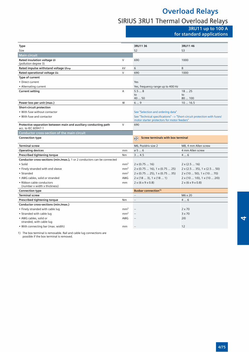
3RU11 up to 100 Afor standard applications
Overload RelaysSIRIUS 3RU1 Thermal Overload Relays
3RU11 up to 100 Afor standard applications
Type 3RU11 36 3RU11 46
Size S2 S3
Main circuitRated insulation voltage Ui
(pollution degree 3)V 690 1000
Rated impulse withstand voltage Uimp kV 6 8
Rated operational voltage Ue V 690 1000
Type of current
• Direct current Yes
• Alternating current Yes, frequency range up to 400 Hz
Current setting A 5.5 ... 8 to 40 ... 50
18 ... 25 to 80 ... 100
Power loss per unit (max.) W 6 ... 9 10 ... 16.5
Short-circuit protection
• With fuse without contactor See "Selection and ordering data"
• With fuse and contactor See "Technical specifications" --> "Short-circuit protection with fuses/motor starter protectors for motor feeders"
Protective separation between main and auxiliary conducting path acc. to IEC 60947-1
V 690
Conductor cross-section of the main circuitConnection type Screw terminals with box terminal
Terminal screw M6, Pozidriv size 2 M8, 4 mm Allen screw
Operating devices mm ø 5 ... 6 4 mm Allen screw
Prescribed tightening torque Nm 3 ... 4.5 4 ... 6
Conductor cross-sections (min./max.), 1 or 2 conductors can be connected
• Solid mm2 2 x (0.75 ... 16) 2 x (2.5 ... 16)
• Finely stranded with end sleeve mm2 2 x (0.75 ... 16), 1 x (0.75 ... 25) 2 x (2.5 ... 35), 1 x (2.5 ... 50)
• Stranded mm2 2 x (0.75 ... 25), 1 x (0.75 ... 35) 2 x (10 ... 50), 1 x (10 ... 70)
• AWG cables, solid or stranded AWG 2 x (18 ... 3), 1 x (18 ... 1) 2 x (10 ... 1/0), 1 x (10 ... 2/0)
• Ribbon cable conductors (number x width x thickness)
mm 2 x (6 x 9 x 0.8) 2 x (6 x 9 x 0.8)
Connection type Busbar connection1)
Terminal screw -- M6 x 20
Prescribed tightening torque Nm -- 4 ... 6
Conductor cross-sections (min./max.)
• Finely stranded with cable lug mm2 -- 2 x 70
• Stranded with cable lug mm2 -- 3 x 70
• AWG cables, solid or stranded, with cable lug
AWG -- 2/0
• With connecting bar (max. width) mm -- 12
1) The box terminal is removable. Rail and cable lug connections are possible if the box terminal is removed.
4/75
4
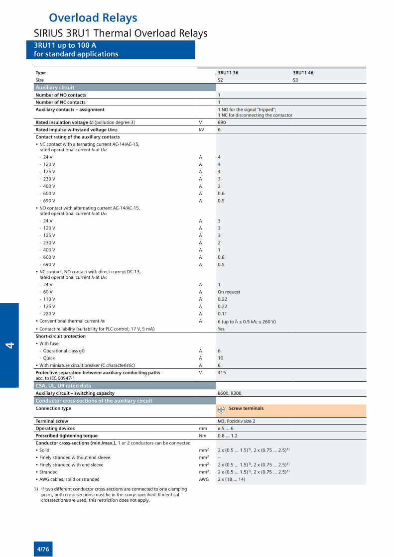
3RU11 up to 100 Afor standard applications
Overload RelaysSIRIUS 3RU1 Thermal Overload Relays3RU11 up to 100 Afor standard applications
Type 3RU11 36 3RU11 46
Size S2 S3
Auxiliary circuitNumber of NO contacts 1
Number of NC contacts 1
Auxiliary contacts – assignment 1 NO for the signal "tripped"; 1 NC for disconnecting the contactor
Rated insulation voltage Ui (pollution degree 3) V 690
Rated impulse withstand voltage Uimp kV 6
Contact rating of the auxiliary contacts
• NC contact with alternating current AC-14/AC-15, rated operational current Ie at Ue:
- 24 V A 4
- 120 V A 4
- 125 V A 4
- 230 V A 3
- 400 V A 2
- 600 V A 0.6
- 690 V A 0.5
• NO contact with alternating current AC-14/AC-15, rated operational current Ie at Ue:
- 24 V A 3
- 120 V A 3
- 125 V A 3
- 230 V A 2
- 400 V A 1
- 600 V A 0.6
- 690 V A 0.5
• NC contact, NO contact with direct current DC-13, rated operational current Ie at Ue:
- 24 V A 1
- 60 V A On request
- 110 V A 0.22
- 125 V A 0.22
- 220 V A 0.11
• Conventional thermal current Ith A 6 (up to Ik ≤ 0.5 kA; ≤ 260 V)
• Contact reliability (suitability for PLC control; 17 V, 5 mA) Yes
Short-circuit protection
• With fuse
- Operational class gG A 6
- Quick A 10
• With miniature circuit breaker (C characteristic) A 6
Protective separation between auxiliary conducting paths acc. to IEC 60947-1
V 415
CSA, UL, UR rated dataAuxiliary circuit – switching capacity B600, R300
Conductor cross-sections of the auxiliary circuitConnection type Screw terminals
Terminal screw M3, Pozidriv size 2
Operating devices mm ø 5 ... 6
Prescribed tightening torque Nm 0.8 ... 1.2
Conductor cross-sections (min./max.), 1 or 2 conductors can be connected
• Solid mm2 2 x (0.5 ... 1.5)1), 2 x (0.75 ... 2.5)1)
• Finely stranded without end sleeve mm2 --
• Finely stranded with end sleeve mm2 2 x (0.5 ... 1.5)1), 2 x (0.75 ... 2.5)1)
• Stranded mm2 2 x (0.5 ... 1.5)1), 2 x (0.75 ... 2.5)1)
• AWG cables, solid or stranded AWG 2 x (18 ... 14)
1) If two different conductor cross-sections are connected to one clamping point, both cross-sections must lie in the range specified. If identical crosssections are used, this restriction does not apply.
4/76
4
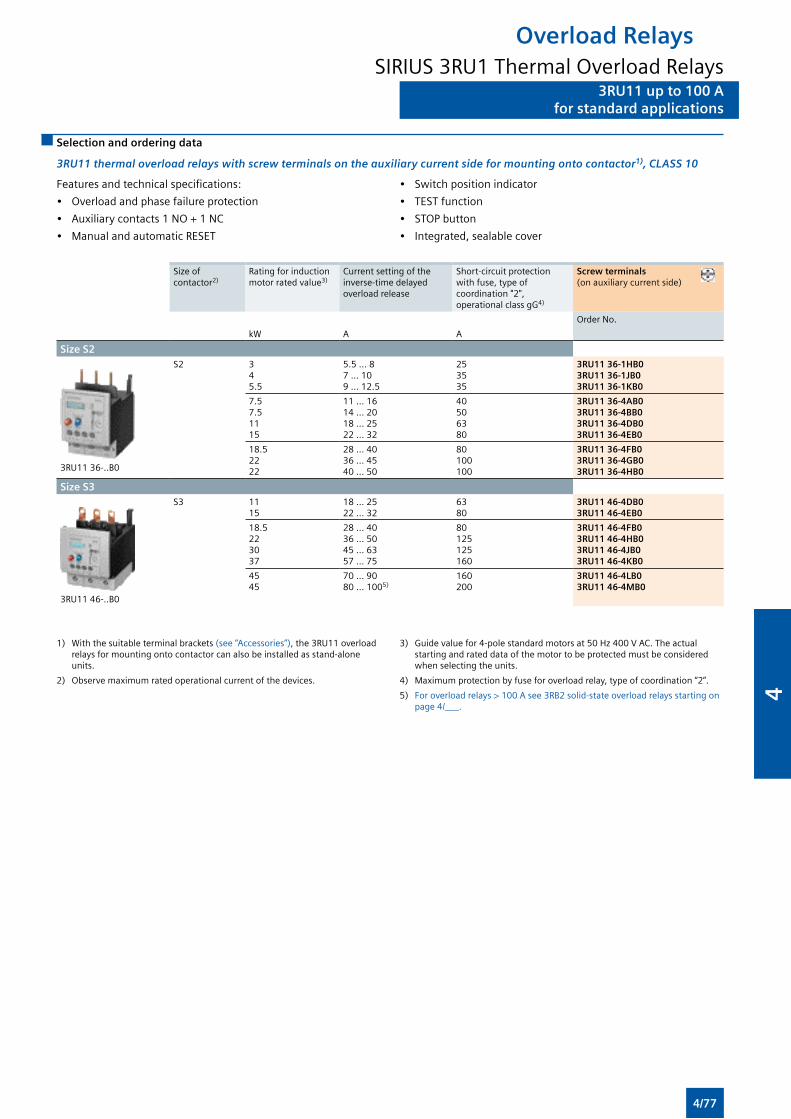
3RU11 up to 100 Afor standard applications
Overload RelaysSIRIUS 3RU1 Thermal Overload Relays
3RU11 up to 100 Afor standard applications
Selection and ordering data
3RU11 thermal overload relays with screw terminals on the auxiliary current side for mounting onto contactor1), CLASS 10
Features and technical specifications:
• Overload and phase failure protection
• Auxiliary contacts 1 NO + 1 NC
• Manual and automatic RESET
• Switch position indicator
• TEST function
• STOP button
• Integrated, sealable cover
Size of contactor2)
Rating for induction motor rated value3)
Current setting of the inverse-time delayed overload release
Short-circuit protection with fuse, type of coordination "2", operational class gG4)
Screw terminals (on auxiliary current side)
Order No.
kW A A
Size S2
3RU11 36-..B0
S2 3 4 5.5
5.5 ... 8 7 ... 10 9 ... 12.5
25 35 35
3RU11 36-1HB03RU11 36-1JB03RU11 36-1KB0
7.5 7.5 11 15
11 ... 16 14 ... 20 18 ... 25 22 ... 32
40 50 63 80
3RU11 36-4AB03RU11 36-4BB03RU11 36-4DB03RU11 36-4EB0
18.5 22 22
28 ... 40 36 ... 45 40 ... 50
80 100 100
3RU11 36-4FB03RU11 36-4GB03RU11 36-4HB0
Size S3
3RU11 46-..B0
S3 11 15
18 ... 25 22 ... 32
63 80
3RU11 46-4DB03RU11 46-4EB0
18.5 22 30 37
28 ... 40 36 ... 50 45 ... 63 57 ... 75
80 125 125160
3RU11 46-4FB03RU11 46-4HB03RU11 46-4JB03RU11 46-4KB0
45 45
70 ... 90 80 ... 1005)
160 200
3RU11 46-4LB03RU11 46-4MB0
1) With the suitable terminal brackets (see “Accessories”), the 3RU11 overload relays for mounting onto contactor can also be installed as stand-alone units.
2) Observe maximum rated operational current of the devices.
3) Guide value for 4-pole standard motors at 50 Hz 400 V AC. The actual starting and rated data of the motor to be protected must be considered when selecting the units.
4) Maximum protection by fuse for overload relay, type of coordination “2”.
5) For overload relays > 100 A see 3RB2 solid-state overload relays starting on page 4/___.
4/77
4
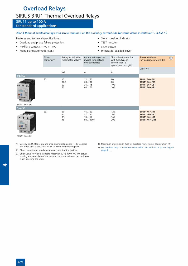
3RU11 up to 100 Afor standard applications
Overload RelaysSIRIUS 3RU1 Thermal Overload Relays3RU11 up to 100 Afor standard applications
3RU11 thermal overload relays with screw terminals on the auxiliary current side for stand-alone installation1), CLASS 10
Features and technical specifications:
• Overload and phase failure protection
• Auxiliary contacts 1 NO + 1 NC
• Manual and automatic RESET
• Switch position indicator
• TEST function
• STOP button
• Integrated, sealable cover
Size of contactor2)
Rating for induction motor rated value3)
Current setting of the inverse-time delayed overload release
Short-circuit protection with fuse, type of coordination "2", operational class gG4)
Screw terminals (on auxiliary current side)
Order No.
kW A A
Size S2
3RU11 36-4EB1
S2 15 18.5 22 22
22 ... 32 28 ... 40 36 ... 45 40 ... 50
80 80 100 100
3RU11 36-4EB13RU11 36-4FB13RU11 36-4GB13RU11 36-4HB1
Size S3
3RU11 46-4JB1
S3 30 37 45 45
45 ... 63 57 ... 75 70 ... 90 80 ... 1005)
125 160 160200
3RU11 46-4JB13RU11 46-4KB13RU11 46-4LB13RU11 46-4MB1
1) Sizes S2 and S3 for screw and snap-on mounting onto TH 35 standard mounting rails, size S3 also for TH 75 standard mounting rails.
2) Observe maximum rated operational current of the devices.
3) Guide value for 4-pole standard motors at 50 Hz 400 V AC. The actual starting and rated data of the motor to be protected must be considered when selecting the units.
4) Maximum protection by fuse for overload relay, type of coordination “2”.
5) For overload relays > 100 A see 3RB2 solid-state overload relays starting on page 4/___.
4/78
4
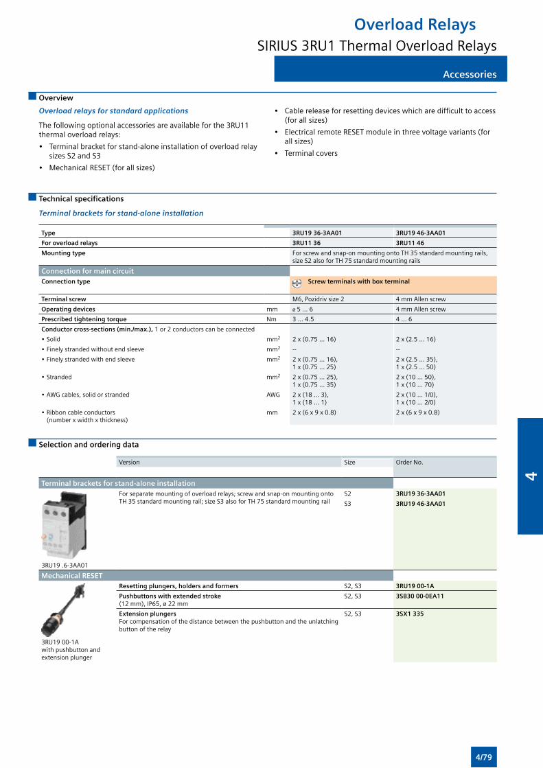
Accessories
Overload RelaysSIRIUS 3RU1 Thermal Overload Relays
Accessories
Overview
Overload relays for standard applications
The following optional accessories are available for the 3RU11 thermal overload relays:
• Terminal bracket for stand-alone installation of overload relay sizes S2 and S3
• Mechanical RESET (for all sizes)
• Cable release for resetting devices which are difficult to access (for all sizes)
• Electrical remote RESET module in three voltage variants (for all sizes)
• Terminal covers
Technical specifications
Terminal brackets for stand-alone installation
Type 3RU19 36-3AA01 3RU19 46-3AA01
For overload relays 3RU11 36 3RU11 46
Mounting type For screw and snap-on mounting onto TH 35 standard mounting rails, size S2 also for TH 75 standard mounting rails
Connection for main circuitConnection type Screw terminals with box terminal
Terminal screw M6, Pozidriv size 2 4 mm Allen screw
Operating devices mm ø 5 ... 6 4 mm Allen screw
Prescribed tightening torque Nm 3 ... 4.5 4 ... 6
Conductor cross-sections (min./max.), 1 or 2 conductors can be connected
• Solid mm2 2 x (0.75 ... 16) 2 x (2.5 ... 16)
• Finely stranded without end sleeve mm2 -- --
• Finely stranded with end sleeve mm2 2 x (0.75 ... 16), 1 x (0.75 ... 25)
2 x (2.5 ... 35), 1 x (2.5 ... 50)
• Stranded mm2 2 x (0.75 ... 25), 1 x (0.75 ... 35)
2 x (10 ... 50), 1 x (10 ... 70)
• AWG cables, solid or stranded AWG 2 x (18 ... 3), 1 x (18 ... 1)
2 x (10 ... 1/0), 1 x (10 ... 2/0)
• Ribbon cable conductors (number x width x thickness)
mm 2 x (6 x 9 x 0.8) 2 x (6 x 9 x 0.8)
Selection and ordering data
Version Size Order No.
Terminal brackets for stand-alone installation
3RU19 .6-3AA01
For separate mounting of overload relays; screw and snap-on mounting onto TH 35 standard mounting rail; size S3 also for TH 75 standard mounting rail
S2 3RU19 36-3AA01
S3 3RU19 46-3AA01
Mechanical RESET
3RU19 00-1Awith pushbutton and extension plunger
Resetting plungers, holders and formers S2, S3 3RU19 00-1A
Pushbuttons with extended stroke (12 mm), IP65, ø 22 mm
S2, S3 3SB30 00-0EA11
Extension plungers For compensation of the distance between the pushbutton and the unlatching button of the relay
S2, S3 3SX1 335
4/79
4
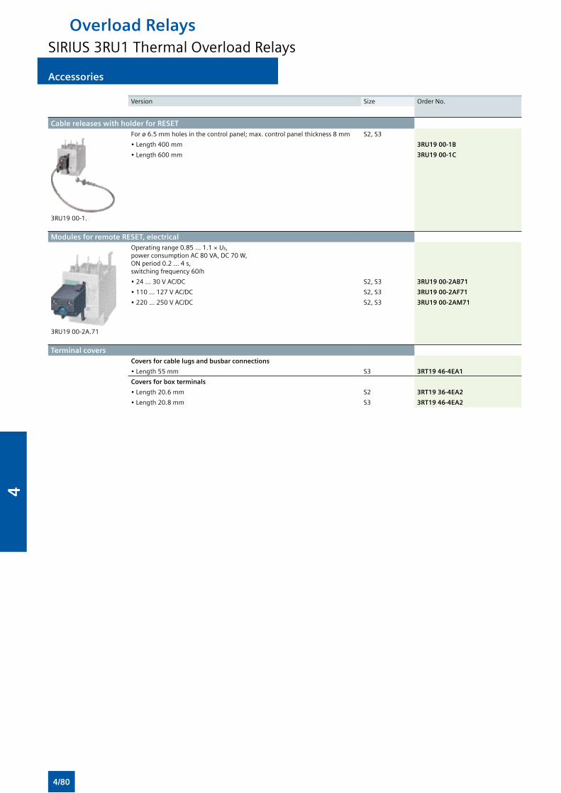
Accessories
Overload RelaysSIRIUS 3RU1 Thermal Overload Relays
Accessories
Version Size Order No.
Cable releases with holder for RESET
3RU19 00-1.
For ø 6.5 mm holes in the control panel; max. control panel thickness 8 mm S2, S3
• Length 400 mm 3RU19 00-1B
• Length 600 mm 3RU19 00-1C
Modules for remote RESET, electrical
3RU19 00-2A.71
Operating range 0.85 ... 1.1 × Us, power consumption AC 80 VA, DC 70 W,ON period 0.2 ... 4 s,switching frequency 60/h
• 24 ... 30 V AC/DC S2, S3 3RU19 00-2AB71
• 110 ... 127 V AC/DC S2, S3 3RU19 00-2AF71
• 220 ... 250 V AC/DC S2, S3 3RU19 00-2AM71
Terminal coversCovers for cable lugs and busbar connections
• Length 55 mm S3 3RT19 46-4EA1
Covers for box terminals
• Length 20.6 mm S2 3RT19 36-4EA2
• Length 20.8 mm S3 3RT19 46-4EA2
4/80
4
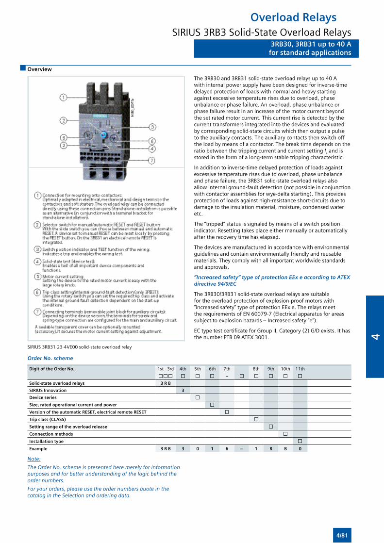
3RB30, 3RB31 up to 40 Afor standard applications
3RB30, 3RB31 up to 40 Afor standard applications
Overview
SIRIUS 3RB31 23-4VE00 solid-state overload relay
The 3RB30 and 3RB31 solid-state overload relays up to 40 A with internal power supply have been designed for inverse-time delayed protection of loads with normal and heavy starting against excessive temperature rises due to overload, phase unbalance or phase failure. An overload, phase unbalance or phase failure result in an increase of the motor current beyond the set rated motor current. This current rise is detected by the current transformers integrated into the devices and evaluated by corresponding solid-state circuits which then output a pulse to the auxiliary contacts. The auxiliary contacts then switch off the load by means of a contactor. The break time depends on the ratio between the tripping current and current setting Ie and is stored in the form of a long-term stable tripping characteristic.
In addition to inverse-time delayed protection of loads against excessive temperature rises due to overload, phase unbalance and phase failure, the 3RB31 solid-state overload relays also allow internal ground-fault detection (not possible in conjunction with contactor assemblies for wye-delta starting). This provides protection of loads against high-resistance short-circuits due to damage to the insulation material, moisture, condensed water etc.
The “tripped” status is signaled by means of a switch position indicator. Resetting takes place either manually or automatically after the recovery time has elapsed.
The devices are manufactured in accordance with environmental guidelines and contain environmentally friendly and reusable materials. They comply with all important worldwide standards and approvals.
“Increased safety” type of protection EEx e according to ATEX directive 94/9/EC
The 3RB30/3RB31 solid-state overload relays are suitable for the overload protection of explosion-proof motors with “increased safety” type of protection EEx e. The relays meet the requirements of EN 60079-7 (Electrical apparatus for areas subject to explosion hazards – Increased safety “e”).
EC type test certificate for Group II, Category (2) G/D exists. It has the number PTB 09 ATEX 3001.
Order No. scheme
Digit of the Order No. 1st - 3rd 4th 5th 6th 7th 8th 9th 10th 11th
–
Solid-state overload relays 3 R B
SIRIUS Innovation 3
Device series
Size, rated operational current and power
Version of the automatic RESET, electrical remote RESET
Trip class (CLASS)
Setting range of the overload release
Connection methods
Installation type
Example 3 R B 3 0 1 6 – 1 R B 0
Note:
The Order No. scheme is presented here merely for information purposes and for better understanding of the logic behind the order numbers.
For your orders, please use the order numbers quote in the catalog in the Selection and ordering data.
Overload RelaysSIRIUS 3RB3 Solid-State Overload Relays
4/81
4
3RB30, 3RB31 up to 40 Afor standard applications
3RB30, 3RB31 up to 40 Afor standard applications
Application
Industries
The 3RB30/3RB31 solid-state overload relays are suitable for customers from all industries who want to guarantee optimum inverse-time delayed protection of their electrical loads (e.g. motors) under normal and heavy starting conditions (CLASS 5 to 30), minimize project completion times, inventories and power consumption, and optimize plant availability and maintenance management.
Application
The 3RB30/3RB31 solid-state overload relays have been designed for the protection of induction motors in sinusoidal 50/60 Hz voltage networks. The relays are not suitable for the protection of single-phase AC or DC loads.
The 3RU21 thermal overload relay or the 3RB22/3RB23 solid-state overload relay can be used for single-phase AC loads. For DC loads we recommend the 3RU21 thermal overload relay.
Ambient conditions
The devices are insensitive to external influences such as shocks, corrosive ambient conditions, ageing and temperature fluctuations.
For the temperature range from –25 °C to +60 °C, the 3RB30/3RB31 solid-state overload relays compensate the temperature in accordance with IEC 60947-4-1.
Overload RelaysSIRIUS 3RB3 Solid-State Overload Relays
4/82
4
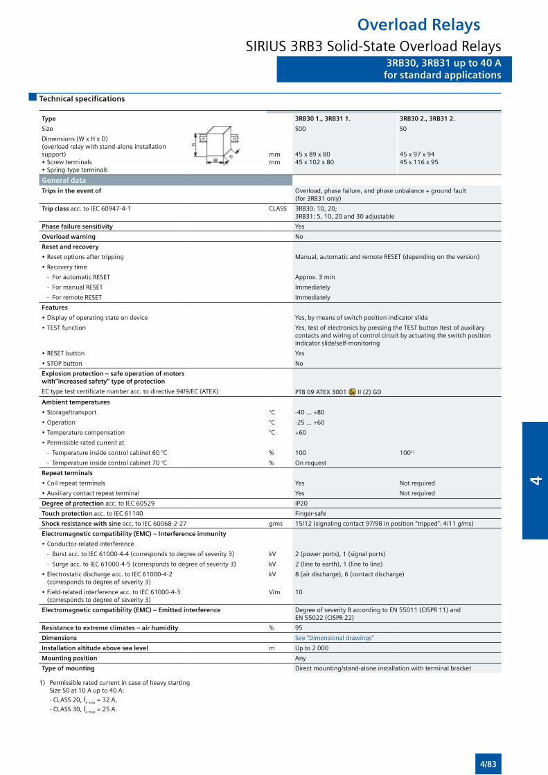
3RB30, 3RB31 up to 40 Afor standard applications
3RB30, 3RB31 up to 40 Afor standard applications
Technical specifications
Type 3RB30 1., 3RB31 1. 3RB30 2., 3RB31 2.
Size S00 S0
Dimensions (W x H x D)(overload relay with stand-alone installation support)• Screw terminals• Spring-type terminals
mmmm
45 x 89 x 8045 x 102 x 80
45 x 97 x 9445 x 116 x 95
General data Trips in the event of Overload, phase failure, and phase unbalance + ground fault
(for 3RB31 only)
Trip class acc. to IEC 60947-4-1 CLASS 3RB30: 10, 20; 3RB31: 5, 10, 20 and 30 adjustable
Phase failure sensitivity Yes
Overload warning No
Reset and recovery
• Reset options after tripping Manual, automatic and remote RESET (depending on the version)
• Recovery time
- For automatic RESET Approx. 3 min
- For manual RESET Immediately
- For remote RESET Immediately
Features
• Display of operating state on device Yes, by means of switch position indicator slide
• TEST function Yes, test of electronics by pressing the TEST button /test of auxiliary contacts and wiring of control circuit by actuating the switch position indicator slide/self-monitoring
• RESET button Yes
• STOP button No
Explosion protection – safe operation of motors with”increased safety” type of protection
EC type test certificate number acc. to directive 94/9/EC (ATEX) PTB 09 ATEX 3001 II (2) GD
Ambient temperatures
• Storage/transport °C -40 ... +80
• Operation °C -25 ... +60
• Temperature compensation °C +60
• Permissible rated current at
- Temperature inside control cabinet 60 °C % 100 1001)
- Temperature inside control cabinet 70 °C % On request
Repeat terminals
• Coil repeat terminals Yes Not required
• Auxiliary contact repeat terminal Yes Not required
Degree of protection acc. to IEC 60529 IP20
Touch protection acc. to IEC 61140 Finger-safe
Shock resistance with sine acc. to IEC 60068-2-27 g/ms 15/12 (signaling contact 97/98 in position “tripped”: 4/11 g/ms)
Electromagnetic compatibility (EMC) – Interference immunity
• Conductor-related interference
- Burst acc. to IEC 61000-4-4 (corresponds to degree of severity 3) kV 2 (power ports), 1 (signal ports)
- Surge acc. to IEC 61000-4-5 (corresponds to degree of severity 3) kV 2 (line to earth), 1 (line to line)
• Electrostatic discharge acc. to IEC 61000-4-2 (corresponds to degree of severity 3)
kV 8 (air discharge), 6 (contact discharge)
• Field-related interference acc. to IEC 61000-4-3 (corresponds to degree of severity 3)
V/m 10
Electromagnetic compatibility (EMC) – Emitted interference Degree of severity B according to EN 55011 (CISPR 11) and EN 55022 (CISPR 22)
Resistance to extreme climates – air humidity % 95
Dimensions See “Dimensional drawings”
Installation altitude above sea level m Up to 2 000
Mounting position Any
Type of mounting Direct mounting/stand-alone installation with terminal bracket
1) Permissible rated current in case of heavy starting Size S0 at 10 A up to 40 A:
- CLASS 20, Ie max = 32 A,
- CLASS 30, Ie max = 25 A.
Overload RelaysSIRIUS 3RB3 Solid-State Overload Relays
4/83
4
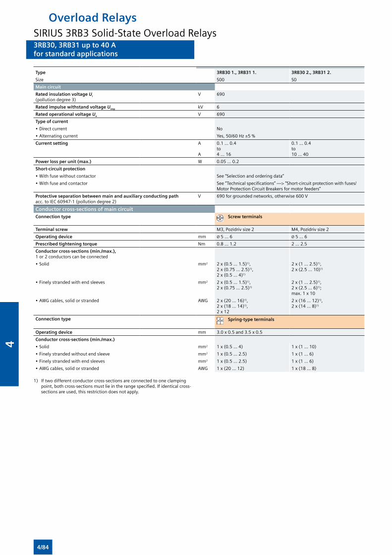
3RB30, 3RB31 up to 40 Afor standard applications
3RB30, 3RB31 up to 40 Afor standard applications
Type 3RB30 1., 3RB31 1. 3RB30 2., 3RB31 2.
Size S00 S0
Main circuit
Rated insulation voltage Ui (pollution degree 3)
V 690
Rated impulse withstand voltage Uimp kV 6
Rated operational voltage Ue V 690
Type of current
• Direct current No
• Alternating current Yes, 50/60 Hz ±5 %
Current setting A A
0.1 ... 0.4 to 4 ... 16
0.1 ... 0.4 to 10 ... 40
Power loss per unit (max.) W 0.05 ... 0.2
Short-circuit protection
• With fuse without contactor See “Selection and ordering data”
• With fuse and contactor See “Technical specifications” —> “Short-circuit protection with fuses/Motor Protection Circuit Breakers for motor feeders”
Protective separation between main and auxiliary conducting path acc. to IEC 60947-1 (pollution degree 2)
V 690 for grounded networks, otherwise 600 V
Conductor cross-sections of main circuitConnection type Screw terminals
Terminal screw M3, Pozidriv size 2 M4, Pozidriv size 2
Operating device mm Ø 5 ... 6 Ø 5 ... 6
Prescribed tightening torque Nm 0.8 ... 1.2 2 ... 2.5
Conductor cross-sections (min./max.), 1 or 2 conductors can be connected
• Solid mm2 2 x (0.5 ... 1.5)1), 2 x (0.75 ... 2.5)1), 2 x (0.5 ... 4)1)
2 x (1 ... 2.5)1), 2 x (2.5 ... 10)1)
• Finely stranded with end sleeves mm2 2 x (0.5 ... 1.5)1), 2 x (0.75 ... 2.5)1)
2 x (1 ... 2.5)1), 2 x (2.5 ... 6)1); max. 1 x 10
• AWG cables, solid or stranded AWG 2 x (20 ... 16)1), 2 x (18 ... 14)1),2 x 12
2 x (16 ... 12)1), 2 x (14 ... 8)1)
Connection type Spring-type terminals
Operating device mm 3.0 x 0.5 and 3.5 x 0.5
Conductor cross-sections (min./max.)
• Solid mm2 1 x (0.5 ... 4) 1 x (1 ... 10)
• Finely stranded without end sleeve mm2 1 x (0.5 ... 2.5) 1 x (1 ... 6)
• Finely stranded with end sleeves mm2 1 x (0.5 ... 2.5) 1 x (1 ... 6)
• AWG cables, solid or stranded AWG 1 x (20 ... 12) 1 x (18 ... 8)
1) If two different conductor cross-sections are connected to one clamping point, both cross-sections must lie in the range specified. If identical cross-sections are used, this restriction does not apply.
Overload RelaysSIRIUS 3RB3 Solid-State Overload Relays
4/84
4
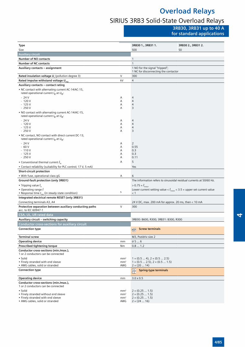
3RB30, 3RB31 up to 40 Afor standard applications
3RB30, 3RB31 up to 40 Afor standard applications
Type 3RB30 1., 3RB31 1. 3RB30 2., 3RB31 2.
Size S00 S0
Auxiliary circuit
Number of NO contacts 1
Number of NC contacts 1
Auxiliary contacts – assignment 1 NO for the signal “tripped”; 1 NC for disconnecting the contactor
Rated insulation voltage Ui (pollution degree 3) V 300
Rated impulse withstand voltage Uimp kV 4
Auxiliary contacts – contact rating
• NC contact with alternating current AC-14/AC-15, rated operational current Ie at Ue:
- 24 V - 120 V - 125 V - 250 V
AAAA
4443
• NO contact with alternating current AC-14/AC-15, rated operational current Ie at Ue:
- 24 V - 120 V - 125 V - 250 V
AAAA
4443
• NC contact, NO contact with direct current DC-13, rated operational current Ie at Ue:
- 24 V - 60 V - 110 V - 125 V - 250 V
AAAAA
20.550.30.30.11
• Conventional thermal current IthA 5
• Contact reliability (suitability for PLC control; 17 V, 5 mA) Yes
Short-circuit protection
• With fuse, operational class gG A 6
Ground-fault protection (only 3RB31) The information refers to sinusoidal residual currents at 50/60 Hz.
• Tripping value ID
• Operating range I• Response time ttrip (in steady-state condition) s
> 0.75 × Imotor
Lower current setting value < Imotor < 3.5 × upper set current value< 1
Integrated electrical remote RESET (only 3RB31)
Connecting terminals A3, A4 24 V DC, max. 200 mA for approx. 20 ms, then < 10 mA
Protective separation between auxiliary conducting paths acc. to IEC 60947-1
V 300
CSA, UL, UR rated dataAuxiliary circuit – switching capacity 3RB30: B600, R300; 3RB31: B300, R300
Conductor cross-sections for auxiliary circuitConnection type Screw terminals
Terminal screw M3, Pozidriv size 2
Operating device mm Ø 5 ... 6
Prescribed tightening torque Nm 0.8 ... 1.2
Conductor cross-sections (min./max.), 1 or 2 conductors can be connected
• Solid• Finely stranded with end sleeve• AWG cables, solid or stranded
mm2
mm2
AWG
1 × (0.5 ... 4), 2 × (0.5 ... 2.5)1 × (0.5 ... 2.5), 2 × (0.5 ... 1.5)2 × (20 ... 14)
Connection type Spring-type terminals
Operating device mm 3.0 x 0.5
Conductor cross-sections (min./max.), 1 or 2 conductors can be connected
• Solid• Finely stranded without end sleeve• Finely stranded with end sleeve• AWG cables, solid or stranded
mm2
mm2
mm2
AWG
2 × (0.25 ... 1.5)2 × (0.25 ... 1.5)2 × (0.25 ... 1.5)2 × (24 ... 16)
Overload RelaysSIRIUS 3RB3 Solid-State Overload Relays
4/85
4
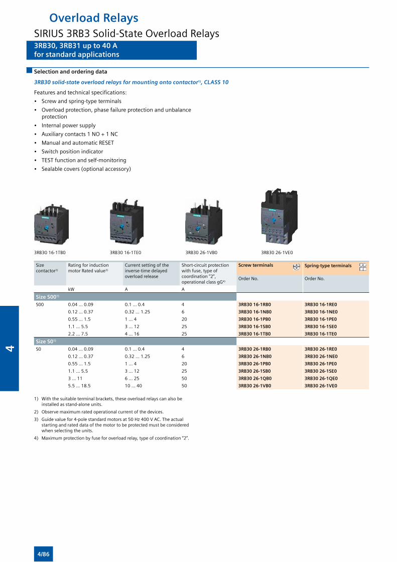
3RB30, 3RB31 up to 40 Afor standard applications
3RB30, 3RB31 up to 40 Afor standard applications
Selection and ordering data
3RB30 solid-state overload relays for mounting onto contactor1), CLASS 10
Features and technical specifications:
• Screw and spring-type terminals
• Overload protection, phase failure protection and unbalance protection
• Internal power supply
• Auxiliary contacts 1 NO + 1 NC
• Manual and automatic RESET
• Switch position indicator
• TEST function and self-monitoring
• Sealable covers (optional accessory)
3RB30 16-1TB0 3RB30 16-1TE0 3RB30 26-1VB0 3RB30 26-1VE0
Size contactor2)
Rating for induction motor Rated value3)
Current setting of the inverse-time delayed overload release
Short-circuit protection with fuse, type of coordination “2”, operational class gG4)
Screw terminals Spring-type terminals
Order No. Order No.
kW A A
Size S001)
S00 0.04 … 0.09 0.1 … 0.4 4 3RB30 16-1RB0 3RB30 16-1RE0
0.12 … 0.37 0.32 … 1.25 6 3RB30 16-1NB0 3RB30 16-1NE0
0.55 … 1.5 1 … 4 20 3RB30 16-1PB0 3RB30 16-1PE0
1.1 … 5.5 3 … 12 25 3RB30 16-1SB0 3RB30 16-1SE0
2.2 … 7.5 4 ... 16 25 3RB30 16-1TB0 3RB30 16-1TE0
Size S01)
S0 0.04 … 0.09 0.1 … 0.4 4 3RB30 26-1RB0 3RB30 26-1RE0
0.12 … 0.37 0.32 … 1.25 6 3RB30 26-1NB0 3RB30 26-1NE0
0.55 … 1.5 1 … 4 20 3RB30 26-1PB0 3RB30 26-1PE0
1.1 … 5.5 3 … 12 25 3RB30 26-1SB0 3RB30 26-1SE0
3 … 11 6 … 25 50 3RB30 26-1QB0 3RB30 26-1QE0
5.5 … 18.5 10 ... 40 50 3RB30 26-1VB0 3RB30 26-1VE0
1) With the suitable terminal brackets, these overload relays can also be installed as stand-alone units.
2) Observe maximum rated operational current of the devices.
3) Guide value for 4-pole standard motors at 50 Hz 400 V AC. The actual starting and rated data of the motor to be protected must be considered when selecting the units.
4) Maximum protection by fuse for overload relay, type of coordination “2”.
Overload RelaysSIRIUS 3RB3 Solid-State Overload Relays
4/86
4
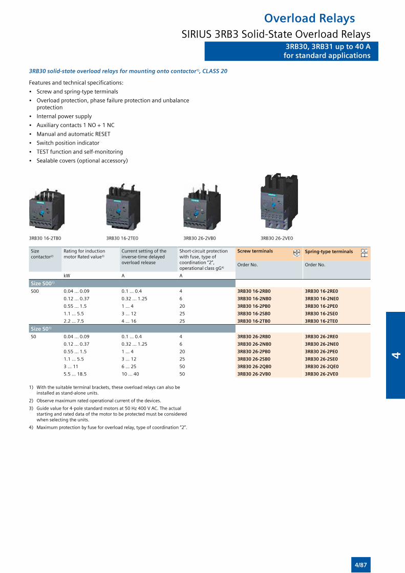
3RB30, 3RB31 up to 40 Afor standard applications
3RB30, 3RB31 up to 40 Afor standard applications
Features and technical specifications:
• Screw and spring-type terminals
• Overload protection, phase failure protection and unbalance protection
• Internal power supply
• Auxiliary contacts 1 NO + 1 NC
• Manual and automatic RESET
• Switch position indicator
• TEST function and self-monitoring
• Sealable covers (optional accessory)
3RB30 solid-state overload relays for mounting onto contactor1), CLASS 20
3RB30 16-2TB0 3RB30 16-2TE0 3RB30 26-2VB0 3RB30 26-2VE0
Size contactor2)
Rating for induction motor Rated value3)
Current setting of the inverse-time delayed overload release
Short-circuit protection with fuse, type of coordination “2”, operational class gG4)
Screw terminals Spring-type terminals
Order No. Order No.
kW A A
Size S001)
S00 0.04 … 0.09 0.1 … 0.4 4 3RB30 16-2RB0 3RB30 16-2RE0
0.12 … 0.37 0.32 … 1.25 6 3RB30 16-2NB0 3RB30 16-2NE0
0.55 … 1.5 1 … 4 20 3RB30 16-2PB0 3RB30 16-2PE0
1.1 … 5.5 3 … 12 25 3RB30 16-2SB0 3RB30 16-2SE0
2.2 … 7.5 4 ... 16 25 3RB30 16-2TB0 3RB30 16-2TE0
Size S01)
S0 0.04 … 0.09 0.1 … 0.4 4 3RB30 26-2RB0 3RB30 26-2RE0
0.12 … 0.37 0.32 … 1.25 6 3RB30 26-2NB0 3RB30 26-2NE0
0.55 … 1.5 1 … 4 20 3RB30 26-2PB0 3RB30 26-2PE0
1.1 … 5.5 3 … 12 25 3RB30 26-2SB0 3RB30 26-2SE0
3 … 11 6 … 25 50 3RB30 26-2QB0 3RB30 26-2QE0
5.5 … 18.5 10 ... 40 50 3RB30 26-2VB0 3RB30 26-2VE0
1) With the suitable terminal brackets, these overload relays can also be installed as stand-alone units.
2) Observe maximum rated operational current of the devices.
3) Guide value for 4-pole standard motors at 50 Hz 400 V AC. The actual starting and rated data of the motor to be protected must be considered when selecting the units.
4) Maximum protection by fuse for overload relay, type of coordination “2”.
Overload RelaysSIRIUS 3RB3 Solid-State Overload Relays
4/87
4

3RB30, 3RB31 up to 40 Afor standard applications
3RB30, 3RB31 up to 40 Afor standard applications
3RB31 solid-state overload relays for mounting onto contactor1), CLASS 5, 10, 20 and 30 adjustable
Features and technical specifications:
• Screw and spring-type terminals
• Overload protection, phase failure protection and unbalance protection
• Internal ground-fault detection (activatable)
• Internal power supply
• Auxiliary contacts 1 NO + 1 NC
• Manual and automatic RESET
• Electrical remote RESET integrated
• Switch position indicator
• TEST function and self-monitoring
• Sealable covers (optional accessory)
3RB31 13-4TB0 3RB31 13-4TE0 3RB31 23-4VB0 3RB31 23-4VE0
Size contactor2)
Rating for induction motor Rated value3)
Current setting of the inverse-time delayed overload release
Short-circuit protection with fuse, type of coordination “2”, operational class gG4)
Screw terminals Spring-type terminals
Order No. Order No.
kW A A
Size S001)
S00 0.04 … 0.09 0.1 … 0.4 4 3RB31 13-4RB0 3RB31 13-4RE0
0.12 … 0.37 0.32 … 1.25 6 3RB31 13-4NB0 3RB31 13-4NE0
0.55 … 1.5 1 … 4 20 3RB31 13-4PB0 3RB31 13-4PE0
1.1 … 5.5 3 … 12 25 3RB31 13-4SB0 3RB31 13-4SE0
2.2 … 7.5 4 ... 16 25 3RB31 13-4TB0 3RB31 13-4TE0
Size S01)
S0 0.04 … 0.09 0.1 … 0.4 4 3RB31 23-4RB0 3RB31 23-4RE0
0.12 … 0.37 0.32 … 1.25 6 3RB31 23-4NB0 3RB31 23-4NE0
0.55 … 1.5 1 … 4 20 3RB31 23-4PB0 3RB31 23-4PE0
1.1 … 5.5 3 … 12 25 3RB31 23-4SB0 3RB31 23-4SE0
3 … 11 6 … 25 50 3RB31 23-4QB0 3RB31 23-4QE0
5.5 … 18.5 10 ... 40 50 3RB31 23-4VB0 3RB31 23-4VE0
1) With the suitable terminal brackets, these overload relays can also be installed as stand-alone units.
2) Observe maximum rated operational current of the devices.
3) Guide value for 4-pole standard motors at 50 Hz 400 V AC. The actual starting and rated data of the motor to be protected must be considered when selecting the units.
4) Maximum protection by fuse for overload relay, type of coordination “2”.
Overload RelaysSIRIUS 3RB3 Solid-State Overload Relays
4/88
4
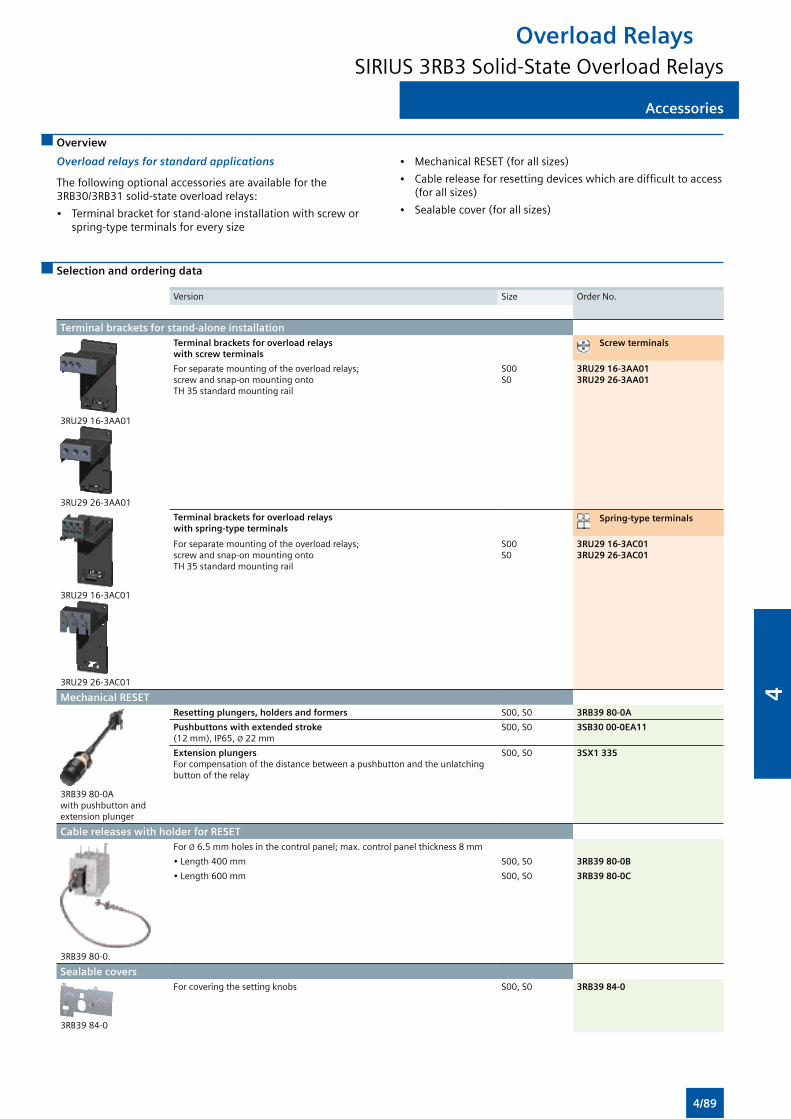
AccessoriesAccessories
Overview
Overload relays for standard applications
The following optional accessories are available for the 3RB30/3RB31 solid-state overload relays:
• Terminal bracket for stand-alone installation with screw or spring-type terminals for every size
• Mechanical RESET (for all sizes)
• Cable release for resetting devices which are difficult to access (for all sizes)
• Sealable cover (for all sizes)
Selection and ordering data
Version Size Order No.
Terminal brackets for stand-alone installation
3RU29 16-3AA01
3RU29 26-3AA01
Terminal brackets for overload relays with screw terminals
Screw terminals
For separate mounting of the overload relays; screw and snap-on mounting onto TH 35 standard mounting rail
S00 S0
3RU29 16-3AA013RU29 26-3AA01
3RU29 16-3AC01
3RU29 26-3AC01
Terminal brackets for overload relays with spring-type terminals
Spring-type terminals
For separate mounting of the overload relays; screw and snap-on mounting onto TH 35 standard mounting rail
S00S0
3RU29 16-3AC013RU29 26-3AC01
Mechanical RESET
3RB39 80-0A with pushbutton and extension plunger
Resetting plungers, holders and formers S00, S0 3RB39 80-0A
Pushbuttons with extended stroke (12 mm), IP65, Ø 22 mm
S00, S0 3SB30 00-0EA11
Extension plungers For compensation of the distance between a pushbutton and the unlatching button of the relay
S00, S0 3SX1 335
Cable releases with holder for RESET
3RB39 80-0.
For Ø 6.5 mm holes in the control panel; max. control panel thickness 8 mm
• Length 400 mm S00, S0 3RB39 80-0B
• Length 600 mm S00, S0 3RB39 80-0C
Sealable covers
3RB39 84-0
For covering the setting knobs S00, S0 3RB39 84-0
Overload RelaysSIRIUS 3RB3 Solid-State Overload Relays
4/89
4
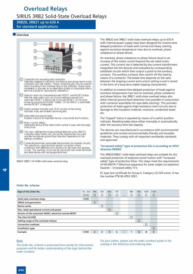
3RB20, 3RB21 up to 630 Afor standard applications
Overload RelaysSIRIUS 3RB2 Solid-State Overload Relays3RB20, 3RB21 up to 630 Afor standard applications
Overview
SIRIUS 3RB21 33-4UB0 solid-state overload relay
The 3RB20 and 3RB21 solid-state overload relays up to 630 A with internal power supply have been designed for inverse-time delayed protection of loads with normal and heavy starting against excessive temperature rises due to overload, phase unbalance or phase failure.
An overload, phase unbalance or phase failure result in an increase of the motor current beyond the set rated motor current. This current rise is detected by the current transformers integrated into the devices and evaluated by corresponding solidstate circuits which then output a pulse to the auxiliary contacts. The auxiliary contacts then switch off the load by means of a contactor. The break time depends on the ratio between the tripping current and current setting Ie and is stored in the form of a long-term stable tripping characteristic.
In addition to inverse-time delayed protection of loads against excessive temperature rises due to overload, phase unbalance and phase failure, the 3RB21 solid-state overload relays also allow internal ground-fault detection (not possible in conjunction with contactor assemblies for wye-delta starting). This provides protection of loads against high-resistance short-circuits due to damage to the insulation material, moisture, condensed water etc.
The “tripped” status is signaled by means of a switch position indicator. Resetting takes place either manually or automatically after the recovery time has elapsed.
The devices are manufactured in accordance with environmental guidelines and contain environmentally friendly and reusable materials. They comply with all important worldwide standards and approvals.
“Increased safety” type of protection EEx e according to ATEX directive 94/9/EC
The 3RB20/3RB21 solid-state overload relays are suitable for the overload protection of explosion-proof motors with “increased safety” type of protection EExe. The relays meet the requirements of EN 60079-7 (Electrical apparatus for areas subject to explosion hazards – Increased safety “e”);
EC type test certificate for Group II, Category (2) G/D exists. It has the number PTB 06 ATEX 3001.
Order No. scheme
Digit of the Order No. 1st - 3rd 4th 5th 6th 7th 8th 9th 10th 11th
–
Solid-state overload relays 3 R B
SIRIUS 2nd generation 2
Device series
Size, rated operational current and power
Version of the automatic RESET, electrical remote RESET
Trip class (CLASS)
Setting range of the overload release
Connection methods
Installation type
Example 3 R B 2 0 3 6 – 1 Q B 0
Note:
The Order No. scheme is presented here merely for information purposes and for better understanding of the logic behind the order numbers.
For your orders, please use the order numbers quote in the catalog in the Selection and ordering data.
4/90
4
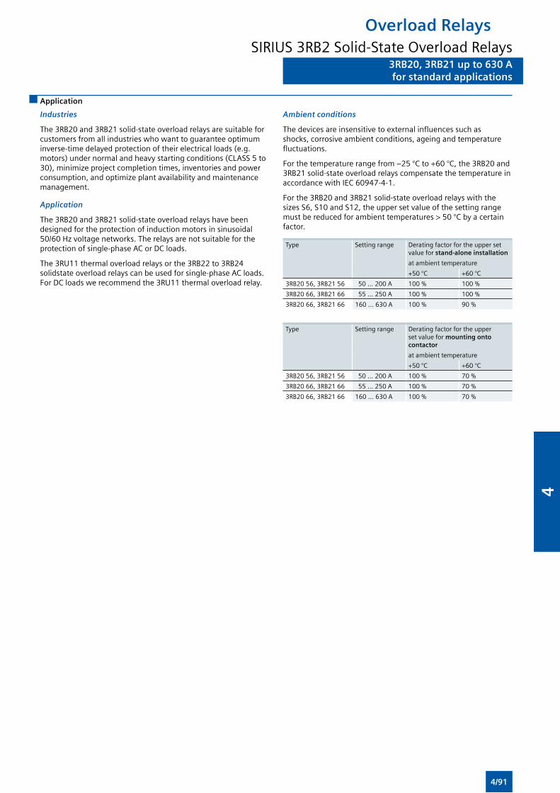
3RB20, 3RB21 up to 630 Afor standard applications
Overload RelaysSIRIUS 3RB2 Solid-State Overload Relays
3RB20, 3RB21 up to 630 Afor standard applications
Application
Industries
The 3RB20 and 3RB21 solid-state overload relays are suitable for customers from all industries who want to guarantee optimum inverse-time delayed protection of their electrical loads (e.g. motors) under normal and heavy starting conditions (CLASS 5 to 30), minimize project completion times, inventories and power consumption, and optimize plant availability and maintenance management.
Application
The 3RB20 and 3RB21 solid-state overload relays have been designed for the protection of induction motors in sinusoidal 50/60 Hz voltage networks. The relays are not suitable for the protection of single-phase AC or DC loads.
The 3RU11 thermal overload relays or the 3RB22 to 3RB24 solidstate overload relays can be used for single-phase AC loads. For DC loads we recommend the 3RU11 thermal overload relay.
Ambient conditions
The devices are insensitive to external influences such as shocks, corrosive ambient conditions, ageing and temperature fluctuations.
For the temperature range from –25 °C to +60 °C, the 3RB20 and 3RB21 solid-state overload relays compensate the temperature in accordance with IEC 60947-4-1.
For the 3RB20 and 3RB21 solid-state overload relays with the sizes S6, S10 and S12, the upper set value of the setting range must be reduced for ambient temperatures > 50 °C by a certain factor.
Type Setting range Derating factor for the upper set value for stand-alone installation
at ambient temperature
+50 °C +60 °C
3RB20 56, 3RB21 56 50 ... 200 A 100 % 100 %
3RB20 66, 3RB21 66 55 ... 250 A 100 % 100 %
3RB20 66, 3RB21 66 160 ... 630 A 100 % 90 %
Type Setting range Derating factor for the upper set value for mounting onto contactor
at ambient temperature
+50 °C +60 °C
3RB20 56, 3RB21 56 50 ... 200 A 100 % 70 %
3RB20 66, 3RB21 66 55 ... 250 A 100 % 70 %
3RB20 66, 3RB21 66 160 ... 630 A 100 % 70 %
4/91
4
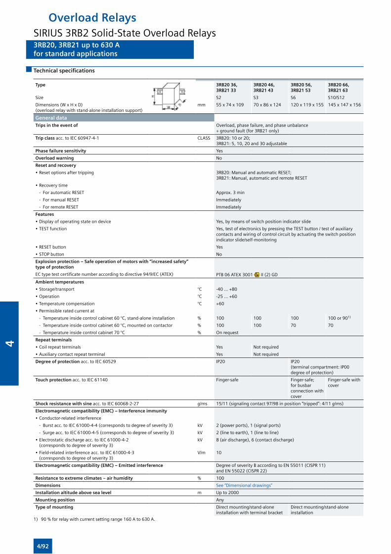
3RB20, 3RB21 up to 630 Afor standard applications
Overload RelaysSIRIUS 3RB2 Solid-State Overload Relays3RB20, 3RB21 up to 630 Afor standard applications
Technical specifications
Type 3RB20 36, 3RB21 33
3RB20 46, 3RB21 43
3RB20 56, 3RB21 53
3RB20 66, 3RB21 63
Size S2 S3 S6 S10/S12
Dimensions (W x H x D)(overload relay with stand-alone installation support)
mm 55 x 74 x 109 70 x 86 x 124 120 x 119 x 155 145 x 147 x 156
General dataTrips in the event of Overload, phase failure, and phase unbalance
+ ground fault (for 3RB21 only)
Trip class acc. to IEC 60947-4-1 CLASS 3RB20: 10 or 20; 3RB21: 5, 10, 20 and 30 adjustable
Phase failure sensitivity Yes
Overload warning No
Reset and recovery
• Reset options after tripping 3RB20: Manual and automatic RESET;3RB21: Manual, automatic and remote RESET
• Recovery time
- For automatic RESET Approx. 3 min
- For manual RESET Immediately
- For remote RESET Immediately
Features
• Display of operating state on device Yes, by means of switch position indicator slide
• TEST function Yes, test of electronics by pressing the TEST button / test of auxiliary contacts and wiring of control circuit by actuating the switch position indicator slide/self-monitoring
• RESET button Yes
• STOP button No
Explosion protection – Safe operation of motors with “increased safety”type of protection
EC type test certificate number according to directive 94/9/EC (ATEX) PTB 06 ATEX 3001 II (2) GD
Ambient temperatures
• Storage/transport °C -40 ... +80
• Operation °C -25 ... +60
• Temperature compensation °C +60
• Permissible rated current at
- Temperature inside control cabinet 60 °C, stand-alone installation % 100 100 100 100 or 901)
- Temperature inside control cabinet 60 °C, mounted on contactor % 100 100 70 70
- Temperature inside control cabinet 70 °C % On request
Repeat terminals
• Coil repeat terminals Yes Not required
• Auxiliary contact repeat terminal Yes Not required
Degree of protection acc. to IEC 60529 IP20 IP20(terminal compartment: IP00 degree of protection)
Touch protection acc. to IEC 61140 Finger-safe Finger-safe; for busbar connection with cover
Finger-safe with cover
Shock resistance with sine acc. to IEC 60068-2-27 g/ms 15/11 (signaling contact 97/98 in position “tripped”: 4/11 g/ms)
Electromagnetic compatibility (EMC) – Interference immunity
• Conductor-related interference
- Burst acc. to IEC 61000-4-4 (corresponds to degree of severity 3) kV 2 (power ports), 1 (signal ports)
- Surge acc. to IEC 61000-4-5 (corresponds to degree of severity 3) kV 2 (line to earth), 1 (line to line)
• Electrostatic discharge acc. to IEC 61000-4-2 (corresponds to degree of severity 3)
kV 8 (air discharge), 6 (contact discharge)
• Field-related interference acc. to IEC 61000-4-3 (corresponds to degree of severity 3)
V/m 10
Electromagnetic compatibility (EMC) – Emitted interference Degree of severity B according to EN 55011 (CISPR 11) and EN 55022 (CISPR 22)
Resistance to extreme climates – air humidity % 100
Dimensions See “Dimensional drawings”
Installation altitude above sea level m Up to 2000
Mounting position Any
Type of mounting Direct mounting/stand-alone installation with terminal bracket
Direct mounting/stand-alone installation
1) 90 % for relay with current setting range 160 A to 630 A.
4/92
4
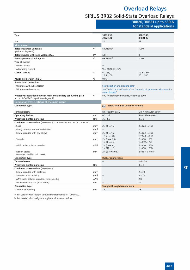
3RB20, 3RB21 up to 630 Afor standard applications
Overload RelaysSIRIUS 3RB2 Solid-State Overload Relays
3RB20, 3RB21 up to 630 Afor standard applications
Type 3RB20 36, 3RB21 33
3RB20 46, 3RB21 43
Size S2 S3
Main circuitRated insulation voltage Ui (pollution degree 3)
V 690/10001) 1000
Rated impulse withstand voltage Uimp kV 6/82) 8
Rated operational voltage Ue V 690/10001) 1000
Type of current
• Direct current No
• Alternating current Yes, 50/60 Hz ±5 %
Current setting A 6 ... 25, 12.5 ... 50
12.5 ... 50, 25 ... 100
Power loss per unit (max.) W 0.05
Short-circuit protection
• With fuse without contactor See “Selection and ordering data”
• With fuse and contactor See “Technical specifications” --> “Short-circuit protection with fuses for motor feeders”
Protective separation between main and auxiliary conducting path Acc. to IEC 60947-1 (pollution degree 2)
V 690 for grounded networks, otherwise 600 V
Conductor cross-sections of the main circuitConnection type Screw terminals with box terminal
Terminal screw M6, Pozidriv size 2 M8, 4 mm Allen screw
Operating devices mm ø 5 ... 6 4 mm Allen screw
Prescribed tightening torque Nm 3 ... 4.5 4 ... 6
Conductor cross-sections (min./max.), 1 or 2 conductors can be connected
• Solid mm2 2 × (1 ... 16) 2 × (2.5 ... 16)
• Finely stranded without end sleeve mm2 -- --
• Finely stranded with end sleeve mm2 2 × (1 ... 16), 1 × ( 1 ... 25)
2 × (2.5 ... 35), 1 × (2.5 ... 50)
• Stranded mm2 2 × (max. 25), 1 × (1 ... 35)
2 × (10 ... 50), 1 × (10 ... 70)
• AWG cables, solid or stranded AWG 2 × (max. 4), 1 × (18 ... 2)
2 × (10 ... 1/0), 1 × (10 ... 2/0)
• Ribbon cables (number x width x thickness)
mm 2 × (6 × 9 × 0.8) 2 × (6 × 9 × 0.8)
Connection type Busbar connections
Terminal screw -- M6 × 20
Prescribed tightening torque Nm -- 4 ... 6
Conductor cross-sections (min./max.)
• Finely stranded with cable lug mm2 -- 2 × 70
• Stranded with cable lug mm2 -- 3 × 70
• AWG cable, solid or stranded, with cable lug AWG -- 2/0
• With connecting bar (max. width) mm -- 12
Connection type Straight-through transformers
Diameter of opening mm 15 18
1) For version with straight-through transformer up to 1 000 V AC.
2) For version with straight-through transformer up to 8 kV.
4/93
4
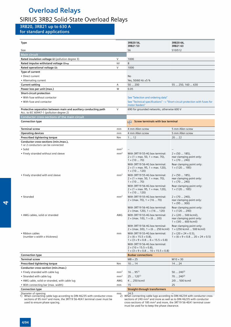
3RB20, 3RB21 up to 630 Afor standard applications
Overload RelaysSIRIUS 3RB2 Solid-State Overload Relays3RB20, 3RB21 up to 630 Afor standard applications
Type 3RB20 56, 3RB21 53
3RB20 66, 3RB21 63
Size S6 S10/S12
Main circuitRated insulation voltage Ui (pollution degree 3) V 1000
Rated impulse withstand voltage Uimp kV 8
Rated operational voltage Ue V 1000
Type of current
• Direct current No
• Alternating current Yes, 50/60 Hz ±5 %
Current setting A 50 ... 200 55 ... 250, 160 ... 630
Power loss per unit (max.) W 0.05
Short-circuit protection
• With fuse without contactor See “Selection and ordering data”
• With fuse and contactor See “Technical specifications” --> “Short-circuit protection with fuses for motor feeders”
Protective separation between main and auxiliary conducting path Acc. to IEC 60947-1 (pollution degree 2)
V 690 for grounded networks, otherwise 600 V
Conductor cross-sections of the main circuitConnection type Screw terminals with box terminal
Terminal screw mm 4 mm Allen screw 5 mm Allen screw
Operating devices mm 4 mm Allen screw 5 mm Allen screw
Prescribed tightening torque Nm 1 ... 12 20 ... 22
Conductor cross-sections (min./max.), 1 or 2 conductors can be connected
• Solid mm2 -- --
• Finely stranded without end sleeve mm 2 With 3RT19 55-4G box terminal: 2 × (1 × max. 50, 1 × max. 70), 1 × (10 ... 70)
2 × (50 ... 185), rear clamping point only: 1 × (70 ... 240)
With 3RT19 56-4G box terminal: 2 × (1 × max. 95, 1 × max. 120), 1 × (10 ... 120)
Rear clamping point only: 1 × (120 ... 185)
• Finely stranded with end sleeve mm2 With 3RT19 55-4G box terminal: 2 × (1 × max. 50, 1 × max. 70), 1 × (10 ... 70)
2 × (50 ... 185), rear clamping point only: 1 × (70 ... 240)
With 3RT19 56-4G box terminal: 2 × (1 × max. 95, 1 × max. 120), 1 × (10 ... 120)
Rear clamping point only: 1 × (120 ... 185)
• Stranded mm2 With 3RT19 55-4G box terminal: 2 × (max. 70), 1 × (16 ... 70)
2 × (70 ... 240), rear clamping point only: 1 × (95 ... 300)
With 3RT19 56-4G box terminal: 2 × (max. 120), 1 × (16 ... 120)
Rear clamping point only: 1 × (120 ... 240)
• AWG cables, solid or stranded AWG With 3RT19 55-4G box terminal: 2 × (max. 1/0), 1 × (6 ... 2/0)
2 × (2/0 ... 500 kcmil), rear clamping point only: 1 × (3/0 ... 600 kcmil)
With 3RT19 56-4G box terminal: 2 × (max. 3/0), 1 × (6 ... 250 kcmil)
Rear clamping point only: 1 × (250 kcmil ... 500 kcmil)
• Ribbon cables (number x width x thickness)
mm With 3RT19 55-4G box terminal: 2 × (6 × 15.5 × 0.8), 1 × (3 × 9 × 0.8 ... 6 × 15.5 × 0.8)
2 × (20 × 24 × 0.5), 1 × (6 × 9 × 0.8 ... 20 × 24 × 0.5)
With 3RT19 56-4G box terminal: 2 × (10 × 15.5 × 0.8), 1 × (3 × 9 × 0.8 ... 10 × 15.5 × 0.8)
Connection type Busbar connections
Terminal screw M8 × 25 M10 × 30
Prescribed tightening torque Nm 10 ... 14 14 ... 24
Conductor cross-section (min./max.)
• Finely stranded with cable lug mm2 16 ... 951) 50 ... 2402)
• Stranded with cable lug mm2 25 ... 1201) 70 ... 2402)
• AWG cable, solid or stranded, with cable lug AWG 4 ... 250 kcmil 2/0 ... 500 kcmil
• With connecting bar (max. width) mm 15 25
Connection type Straight-through transformers
Diameter of opening mm 24.5 --1) When connecting cable lugs according to DIN 46235 with conductor cross-
sections of 95 mm2 and more, the 3RT19 56-4EA1 terminal cover must be used to ensure phase spacing.
2) When connecting cable lugs according to DIN 46234 with conductor cross-sections of 240 mm2 and more as well as to DIN 46235 with conductor cross-sections of 185 mm2 and more, the 3RT19 56-4EA1 terminal cover must be used for to keep the phase clearance.
4/94
4
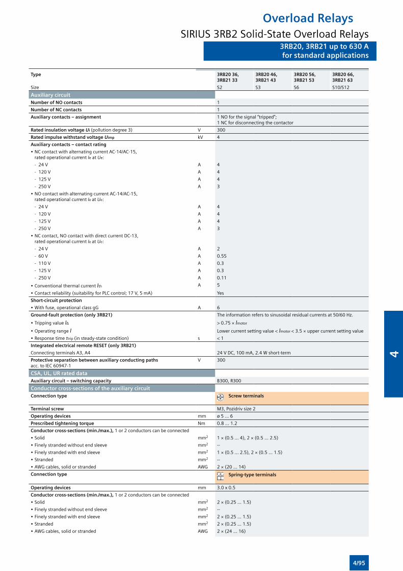
3RB20, 3RB21 up to 630 Afor standard applications
Overload RelaysSIRIUS 3RB2 Solid-State Overload Relays
3RB20, 3RB21 up to 630 Afor standard applications
Type 3RB20 36, 3RB21 33
3RB20 46, 3RB21 43
3RB20 56, 3RB21 53
3RB20 66, 3RB21 63
Size S2 S3 S6 S10/S12
Auxiliary circuitNumber of NO contacts 1
Number of NC contacts 1
Auxiliary contacts – assignment 1 NO for the signal “tripped”;1 NC for disconnecting the contactor
Rated insulation voltage Ui (pollution degree 3) V 300
Rated impulse withstand voltage Uimp kV 4
Auxiliary contacts – contact rating
• NC contact with alternating current AC-14/AC-15, rated operational current Ie at Ue:
- 24 V A 4
- 120 V A 4
- 125 V A 4
- 250 V A 3
• NO contact with alternating current AC-14/AC-15, rated operational current Ie at Ue:
- 24 V A 4
- 120 V A 4
- 125 V A 4
- 250 V A 3
• NC contact, NO contact with direct current DC-13, rated operational current Ie at Ue:
- 24 V A 2
- 60 V A 0.55
- 110 V A 0.3
- 125 V A 0.3
- 250 V A 0.11
• Conventional thermal current Ith A 5
• Contact reliability (suitability for PLC control; 17 V, 5 mA) Yes
Short-circuit protection
• With fuse, operational class gG A 6
Ground-fault protection (only 3RB21) The information refers to sinusoidal residual currents at 50/60 Hz.
• Tripping value IΔ > 0.75 × Imotor
• Operating range I Lower current setting value < Imotor < 3.5 × upper current setting value
• Response time ttrip (in steady-state condition) s < 1
Integrated electrical remote RESET (only 3RB21)
Connecting terminals A3, A4 24 V DC, 100 mA, 2.4 W short-term
Protective separation between auxiliary conducting paths acc. to IEC 60947-1
V 300
CSA, UL, UR rated dataAuxiliary circuit – switching capacity B300, R300
Conductor cross-sections of the auxiliary circuitConnection type Screw terminals
Terminal screw M3, Pozidriv size 2
Operating devices mm ø 5 ... 6
Prescribed tightening torque Nm 0.8 ... 1.2
Conductor cross-sections (min./max.), 1 or 2 conductors can be connected
• Solid mm2 1 × (0.5 ... 4), 2 × (0.5 ... 2.5)
• Finely stranded without end sleeve mm2 --
• Finely stranded with end sleeve mm2 1 × (0.5 ... 2.5), 2 × (0.5 ... 1.5)
• Stranded mm2 --
• AWG cables, solid or stranded AWG 2 × (20 ... 14)
Connection type Spring-type terminals
Operating devices mm 3.0 x 0.5
Conductor cross-sections (min./max.), 1 or 2 conductors can be connected
• Solid mm2 2 × (0.25 ... 1.5)
• Finely stranded without end sleeve mm2 --
• Finely stranded with end sleeve mm2 2 × (0.25 ... 1.5)
• Stranded mm2 2 × (0.25 ... 1.5)
• AWG cables, solid or stranded AWG 2 × (24 ... 16)
4/95
4
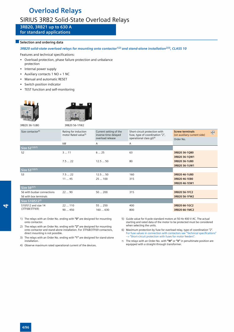
3RB20, 3RB21 up to 630 Afor standard applications
Overload RelaysSIRIUS 3RB2 Solid-State Overload Relays3RB20, 3RB21 up to 630 Afor standard applications
Selection and ordering data
3RB20 solid-state overload relays for mounting onto contactor1)2) and stand-alone installation2)3), CLASS 10
Features and technical specifications:
• Overload protection, phase failure protection and unbalance protection
• Internal power supply
• Auxiliary contacts 1 NO + 1 NC
• Manual and automatic RESET
• Switch position indicator
• TEST function and self-monitoring
3RB20 36-1UB0 3RB20 56-1FW2
Size contactor4) Rating for induction motor Rated value5)
Current setting of the inverse-time delayed overload release
Short-circuit protection with fuse, type of coordination “2”, operational class gG6)
Screw terminals (on auxiliary current side)
Order No.
kW A A
Size S21)3)7)
S2 3 … 11 6 … 25 63 3RB20 36-1QB0
3RB20 36-1QW1
7.5 … 22 12.5 … 50 80 3RB20 36-1UB0
3RB20 36-1UW1
Size S31)3)7)
S3 7.5 … 22 12.5 … 50 160 3RB20 46-1UB0
11 … 45 25 … 100 315 3RB20 46-1EB0
3RB20 46-1EW1
Size S62)7)
S6 with busbar connections 22 … 90 50 … 200 315 3RB20 56-1FC2
S6 with box terminals 3RB20 56-1FW2
Size S10/S122)
S10/S12 and size 14 (3TF68/3TF69)
22 … 110 55 … 250 400 3RB20 66-1GC2
90 … 450 160 … 630 800 3RB20 66-1MC2
1) The relays with an Order No. ending with “0” are designed for mounting onto contactor.
2) The relays with an Order No. ending with “2” are designed for mounting onto contactor and stand-alone installation. For 3TF68/3TF69 contactors, direct mounting is not possible.
3) The relays with an Order No. ending with “1” are designed for stand-alone installation.
4) Observe maximum rated operational current of the devices.
5) Guide value for 4-pole standard motors at 50 Hz 400 V AC. The actual starting and rated data of the motor to be protected must be considered when selecting the units.
6) Maximum protection by fuse for overload relay, type of coordination “2”. For fuse values in connection with contactors see “Technical specifications” --> “Short-circuit protection with fuses for motor feeders”.
7) The relays with an Order No. with “W” or “X” in penultimate position are equipped with a straight-through transformer.
4/96
4
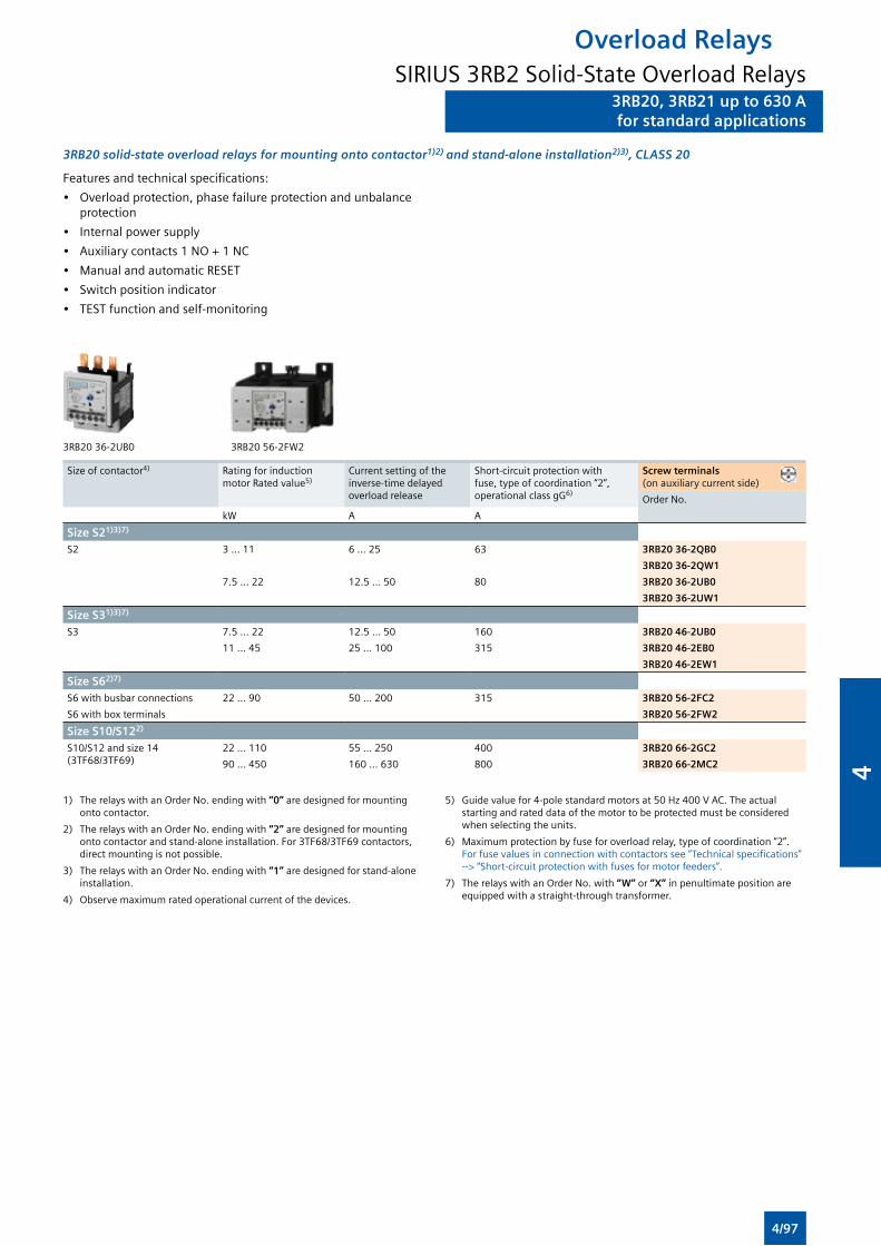
3RB20, 3RB21 up to 630 Afor standard applications
Overload RelaysSIRIUS 3RB2 Solid-State Overload Relays
3RB20, 3RB21 up to 630 Afor standard applications
3RB20 solid-state overload relays for mounting onto contactor1)2) and stand-alone installation2)3), CLASS 20
Features and technical specifications:
• Overload protection, phase failure protection and unbalance protection
• Internal power supply
• Auxiliary contacts 1 NO + 1 NC
• Manual and automatic RESET
• Switch position indicator
• TEST function and self-monitoring
3RB20 36-2UB0 3RB20 56-2FW2
Size of contactor4) Rating for induction motor Rated value5)
Current setting of the inverse-time delayed overload release
Short-circuit protection with fuse, type of coordination “2”, operational class gG6)
Screw terminals (on auxiliary current side)
Order No.
kW A A
Size S21)3)7)
S2 3 … 11 6 … 25 63 3RB20 36-2QB0
3RB20 36-2QW1
7.5 … 22 12.5 … 50 80 3RB20 36-2UB0
3RB20 36-2UW1
Size S31)3)7)
S3 7.5 … 22 12.5 … 50 160 3RB20 46-2UB0
11 … 45 25 … 100 315 3RB20 46-2EB0
3RB20 46-2EW1
Size S62)7)
S6 with busbar connections 22 … 90 50 … 200 315 3RB20 56-2FC2
S6 with box terminals 3RB20 56-2FW2
Size S10/S122)
S10/S12 and size 14 (3TF68/3TF69)
22 … 110 55 … 250 400 3RB20 66-2GC2
90 … 450 160 … 630 800 3RB20 66-2MC2
1) The relays with an Order No. ending with “0” are designed for mounting onto contactor.
2) The relays with an Order No. ending with “2” are designed for mounting onto contactor and stand-alone installation. For 3TF68/3TF69 contactors, direct mounting is not possible.
3) The relays with an Order No. ending with “1” are designed for stand-alone installation.
4) Observe maximum rated operational current of the devices.
5) Guide value for 4-pole standard motors at 50 Hz 400 V AC. The actual starting and rated data of the motor to be protected must be considered when selecting the units.
6) Maximum protection by fuse for overload relay, type of coordination “2”. For fuse values in connection with contactors see “Technical specifications” --> “Short-circuit protection with fuses for motor feeders”.
7) The relays with an Order No. with “W” or “X” in penultimate position are equipped with a straight-through transformer.
4/97
4
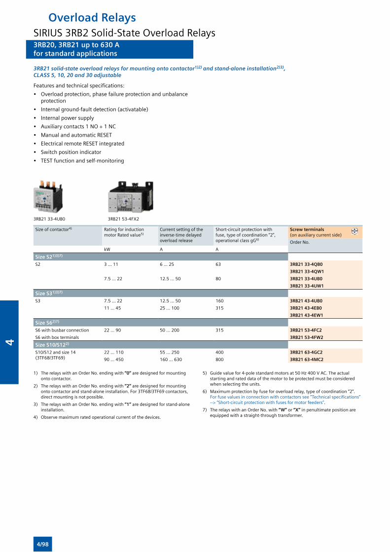
3RB20, 3RB21 up to 630 Afor standard applications
Overload RelaysSIRIUS 3RB2 Solid-State Overload Relays3RB20, 3RB21 up to 630 Afor standard applications
3RB21 solid-state overload relays for mounting onto contactor1)2) and stand-alone installation2)3), CLASS 5, 10, 20 and 30 adjustable
Features and technical specifications:
• Overload protection, phase failure protection and unbalance protection
• Internal ground-fault detection (activatable)
• Internal power supply
• Auxiliary contacts 1 NO + 1 NC
• Manual and automatic RESET
• Electrical remote RESET integrated
• Switch position indicator
• TEST function and self-monitoring
3RB21 33-4UB0 3RB21 53-4FX2
Size of contactor4) Rating for induction motor Rated value5)
Current setting of the inverse-time delayed overload release
Short-circuit protection with fuse, type of coordination “2”, operational class gG6)
Screw terminals (on auxiliary current side)
Order No.
kW A A
Size S21)3)7)
S2 3 … 11 6 … 25 63 3RB21 33-4QB0
3RB21 33-4QW1
7.5 … 22 12.5 … 50 80 3RB21 33-4UB0
3RB21 33-4UW1
Size S31)3)7)
S3 7.5 … 22 12.5 … 50 160 3RB21 43-4UB0
11 … 45 25 … 100 315 3RB21 43-4EB0
3RB21 43-4EW1
Size S62)7)
S6 with busbar connection 22 … 90 50 … 200 315 3RB21 53-4FC2
S6 with box terminals 3RB21 53-4FW2
Size S10/S122)
S10/S12 and size 14 (3TF68/3TF69)
22 … 110 55 … 250 400 3RB21 63-4GC2
90 … 450 160 … 630 800 3RB21 63-4MC2
1) The relays with an Order No. ending with “0” are designed for mounting onto contactor.
2) The relays with an Order No. ending with “2” are designed for mounting onto contactor and stand-alone installation. For 3TF68/3TF69 contactors, direct mounting is not possible.
3) The relays with an Order No. ending with “1” are designed for stand-alone installation.
4) Observe maximum rated operational current of the devices.
5) Guide value for 4-pole standard motors at 50 Hz 400 V AC. The actual starting and rated data of the motor to be protected must be considered when selecting the units.
6) Maximum protection by fuse for overload relay, type of coordination “2”. For fuse values in connection with contactors see “Technical specifications” --> “Short-circuit protection with fuses for motor feeders”.
7) The relays with an Order No. with “W” or “X” in penultimate position are equipped with a straight-through transformer.
4/98
4
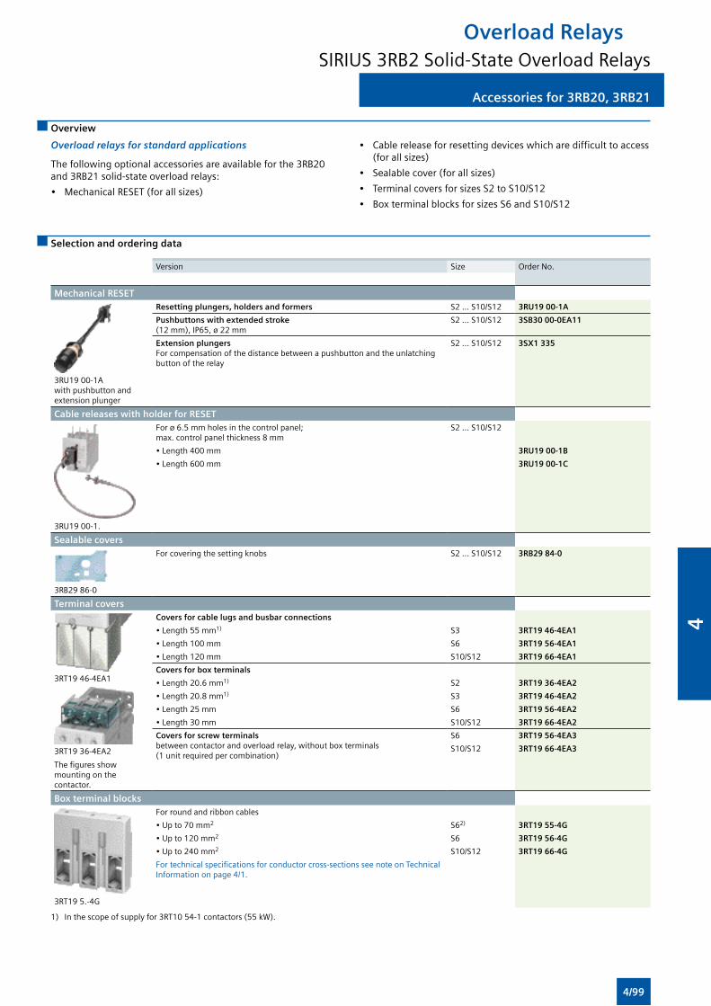
Accessories for 3RB20, 3RB21
Overload RelaysSIRIUS 3RB2 Solid-State Overload Relays
Accessories for 3RB20, 3RB21
Overview
Overload relays for standard applications
The following optional accessories are available for the 3RB20 and 3RB21 solid-state overload relays:
• Mechanical RESET (for all sizes)
• Cable release for resetting devices which are difficult to access (for all sizes)
• Sealable cover (for all sizes)
• Terminal covers for sizes S2 to S10/S12
• Box terminal blocks for sizes S6 and S10/S12
Selection and ordering data
Version Size Order No.
Mechanical RESET
3RU19 00-1A with pushbutton and extension plunger
Resetting plungers, holders and formers S2 ... S10/S12 3RU19 00-1A
Pushbuttons with extended stroke (12 mm), IP65, ø 22 mm
S2 ... S10/S12 3SB30 00-0EA11
Extension plungers For compensation of the distance between a pushbutton and the unlatching button of the relay
S2 ... S10/S12 3SX1 335
Cable releases with holder for RESET
3RU19 00-1.
For ø 6.5 mm holes in the control panel; max. control panel thickness 8 mm
S2 ... S10/S12
• Length 400 mm 3RU19 00-1B
• Length 600 mm 3RU19 00-1C
Sealable covers
3RB29 86-0
For covering the setting knobs S2 ... S10/S12 3RB29 84-0
Terminal covers
3RT19 46-4EA1
3RT19 36-4EA2
The figures show mounting on the contactor.
Covers for cable lugs and busbar connections
• Length 55 mm1) S3 3RT19 46-4EA1
• Length 100 mm S6 3RT19 56-4EA1
• Length 120 mm S10/S12 3RT19 66-4EA1
Covers for box terminals
• Length 20.6 mm1) S2 3RT19 36-4EA2
• Length 20.8 mm1) S3 3RT19 46-4EA2
• Length 25 mm S6 3RT19 56-4EA2
• Length 30 mm S10/S12 3RT19 66-4EA2
Covers for screw terminals between contactor and overload relay, without box terminals (1 unit required per combination)
S6 3RT19 56-4EA3
S10/S12 3RT19 66-4EA3
Box terminal blocks
3RT19 5.-4G
For round and ribbon cables
• Up to 70 mm2 S62) 3RT19 55-4G
• Up to 120 mm2 S6 3RT19 56-4G
• Up to 240 mm2 S10/S12 3RT19 66-4G
For technical specifications for conductor cross-sections see note on Technical Information on page 4/1.
1) In the scope of supply for 3RT10 54-1 contactors (55 kW).
4/99
4
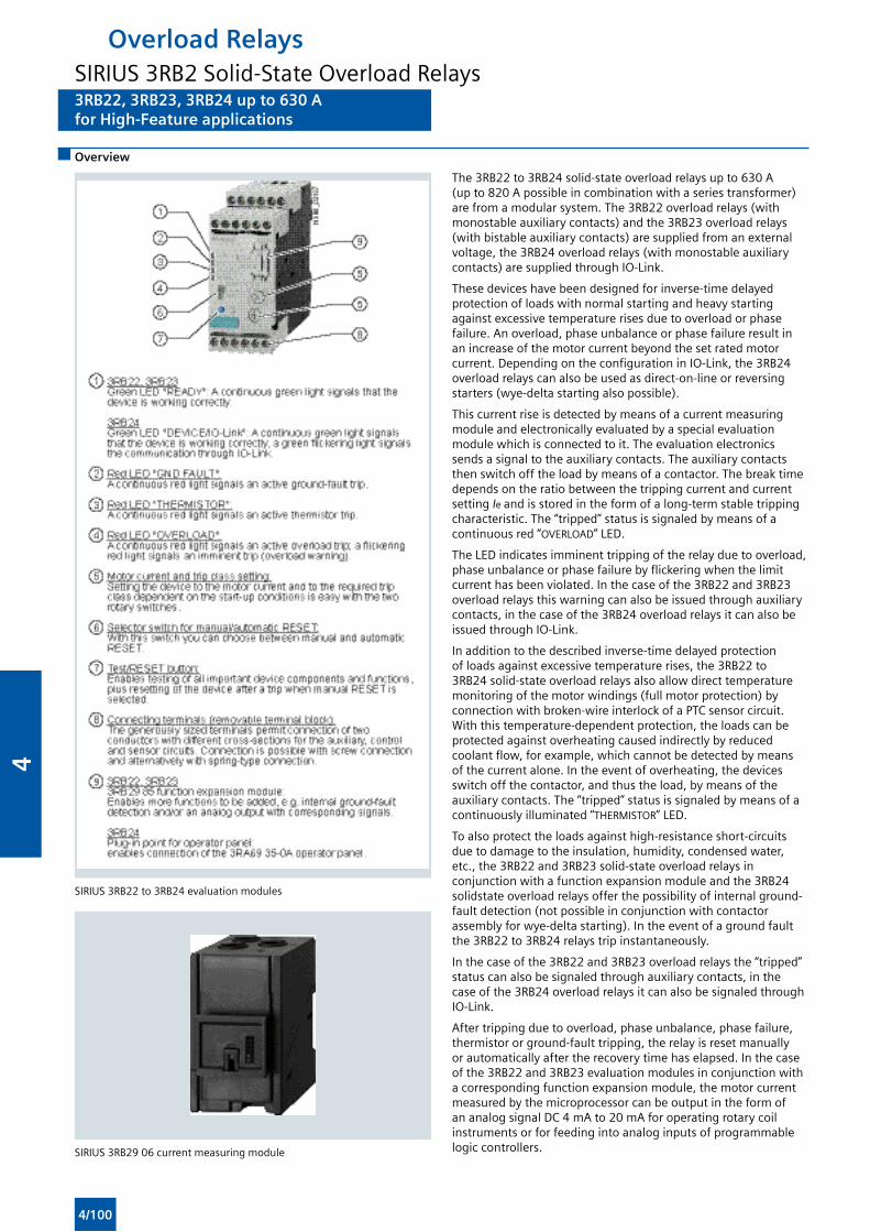
3RB22, 3RB23, 3RB24 up to 630 Afor High-Feature applications
Overload RelaysSIRIUS 3RB2 Solid-State Overload Relays3RB22, 3RB23, 3RB24 up to 630 Afor High-Feature applications
Overview
The 3RB22 to 3RB24 solid-state overload relays up to 630 A (up to 820 A possible in combination with a series transformer) are from a modular system. The 3RB22 overload relays (with monostable auxiliary contacts) and the 3RB23 overload relays (with bistable auxiliary contacts) are supplied from an external voltage, the 3RB24 overload relays (with monostable auxiliary contacts) are supplied through IO-Link.
These devices have been designed for inverse-time delayed protection of loads with normal starting and heavy starting against excessive temperature rises due to overload or phase failure. An overload, phase unbalance or phase failure result in an increase of the motor current beyond the set rated motor current. Depending on the configuration in IO-Link, the 3RB24 overload relays can also be used as direct-on-line or reversing starters (wye-delta starting also possible).
This current rise is detected by means of a current measuring module and electronically evaluated by a special evaluation module which is connected to it. The evaluation electronics sends a signal to the auxiliary contacts. The auxiliary contacts then switch off the load by means of a contactor. The break time depends on the ratio between the tripping current and current setting Ie and is stored in the form of a long-term stable tripping characteristic. The “tripped” status is signaled by means of a continuous red “OVERLOAD” LED.
The LED indicates imminent tripping of the relay due to overload, phase unbalance or phase failure by flickering when the limit current has been violated. In the case of the 3RB22 and 3RB23 overload relays this warning can also be issued through auxiliary contacts, in the case of the 3RB24 overload relays it can also be issued through IO-Link.
In addition to the described inverse-time delayed protection of loads against excessive temperature rises, the 3RB22 to 3RB24 solid-state overload relays also allow direct temperature monitoring of the motor windings (full motor protection) by connection with broken-wire interlock of a PTC sensor circuit. With this temperature-dependent protection, the loads can be protected against overheating caused indirectly by reduced coolant flow, for example, which cannot be detected by means of the current alone. In the event of overheating, the devices switch off the contactor, and thus the load, by means of the auxiliary contacts. The “tripped” status is signaled by means of a continuously illuminated “THERMISTOR” LED.
To also protect the loads against high-resistance short-circuits due to damage to the insulation, humidity, condensed water, etc., the 3RB22 and 3RB23 solid-state overload relays in conjunction with a function expansion module and the 3RB24 solidstate overload relays offer the possibility of internal ground-fault detection (not possible in conjunction with contactor assembly for wye-delta starting). In the event of a ground fault the 3RB22 to 3RB24 relays trip instantaneously.
In the case of the 3RB22 and 3RB23 overload relays the “tripped” status can also be signaled through auxiliary contacts, in the case of the 3RB24 overload relays it can also be signaled through IO-Link.
After tripping due to overload, phase unbalance, phase failure, thermistor or ground-fault tripping, the relay is reset manually or automatically after the recovery time has elapsed. In the case of the 3RB22 and 3RB23 evaluation modules in conjunction with a corresponding function expansion module, the motor current measured by the microprocessor can be output in the form of an analog signal DC 4 mA to 20 mA for operating rotary coil instruments or for feeding into analog inputs of programmable logic controllers.
SIRIUS 3RB22 to 3RB24 evaluation modules
SIRIUS 3RB29 06 current measuring module
4/100
4
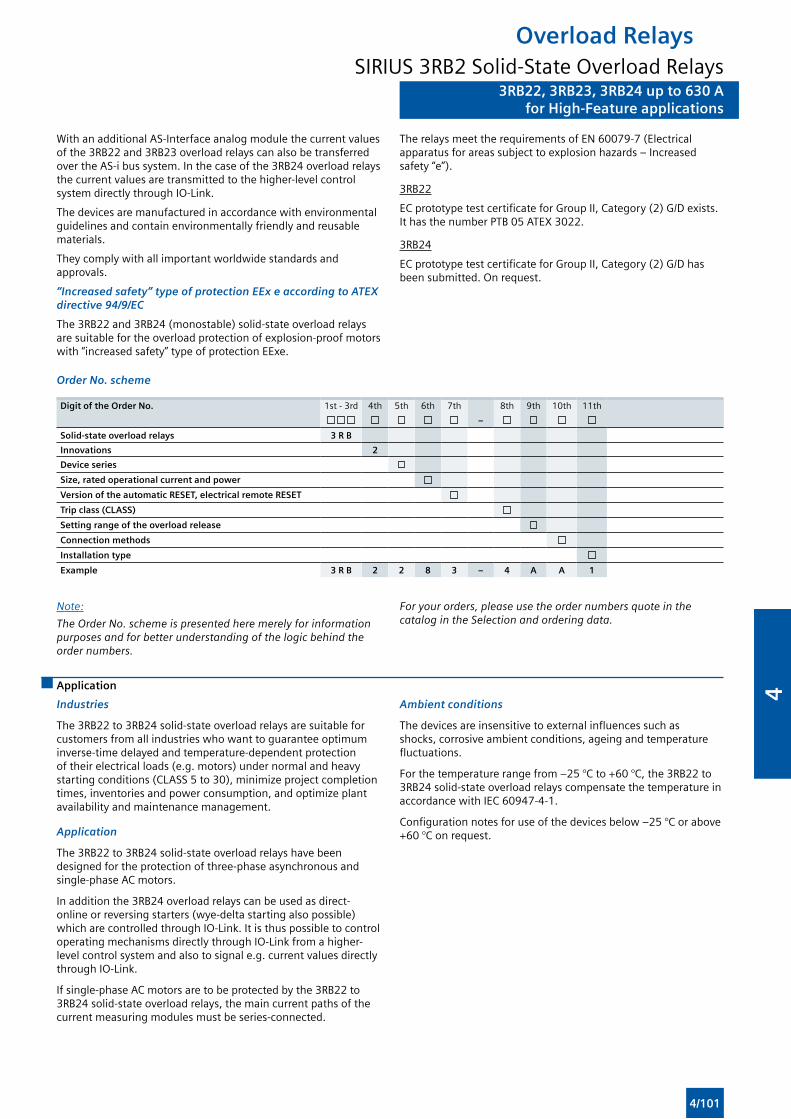
3RB22, 3RB23, 3RB24 up to 630 Afor High-Feature applications
Overload RelaysSIRIUS 3RB2 Solid-State Overload Relays
3RB22, 3RB23, 3RB24 up to 630 Afor High-Feature applications
With an additional AS-Interface analog module the current values of the 3RB22 and 3RB23 overload relays can also be transferred over the AS-i bus system. In the case of the 3RB24 overload relays the current values are transmitted to the higher-level control system directly through IO-Link.
The devices are manufactured in accordance with environmental guidelines and contain environmentally friendly and reusable materials.
They comply with all important worldwide standards and approvals.
“Increased safety” type of protection EEx e according to ATEX directive 94/9/EC
The 3RB22 and 3RB24 (monostable) solid-state overload relays are suitable for the overload protection of explosion-proof motors with “increased safety” type of protection EExe.
The relays meet the requirements of EN 60079-7 (Electrical apparatus for areas subject to explosion hazards – Increased safety “e”).
3RB22
EC prototype test certificate for Group II, Category (2) G/D exists. It has the number PTB 05 ATEX 3022.
3RB24
EC prototype test certificate for Group II, Category (2) G/D has been submitted. On request.
Order No. scheme
Digit of the Order No. 1st - 3rd 4th 5th 6th 7th 8th 9th 10th 11th
–
Solid-state overload relays 3 R B
Innovations 2
Device series
Size, rated operational current and power
Version of the automatic RESET, electrical remote RESET
Trip class (CLASS)
Setting range of the overload release
Connection methods
Installation type
Example 3 R B 2 2 8 3 – 4 A A 1
Note:
The Order No. scheme is presented here merely for information purposes and for better understanding of the logic behind the order numbers.
For your orders, please use the order numbers quote in the catalog in the Selection and ordering data.
Application
Industries
The 3RB22 to 3RB24 solid-state overload relays are suitable for customers from all industries who want to guarantee optimum inverse-time delayed and temperature-dependent protection of their electrical loads (e.g. motors) under normal and heavy starting conditions (CLASS 5 to 30), minimize project completion times, inventories and power consumption, and optimize plant availability and maintenance management.
Application
The 3RB22 to 3RB24 solid-state overload relays have been designed for the protection of three-phase asynchronous and single-phase AC motors.
In addition the 3RB24 overload relays can be used as direct-online or reversing starters (wye-delta starting also possible) which are controlled through IO-Link. It is thus possible to control operating mechanisms directly through IO-Link from a higher-level control system and also to signal e.g. current values directly through IO-Link.
If single-phase AC motors are to be protected by the 3RB22 to 3RB24 solid-state overload relays, the main current paths of the current measuring modules must be series-connected.
Ambient conditions
The devices are insensitive to external influences such as shocks, corrosive ambient conditions, ageing and temperature fluctuations.
For the temperature range from –25 °C to +60 °C, the 3RB22 to 3RB24 solid-state overload relays compensate the temperature in accordance with IEC 60947-4-1.
Configuration notes for use of the devices below –25 °C or above +60 °C on request.
4/101
4
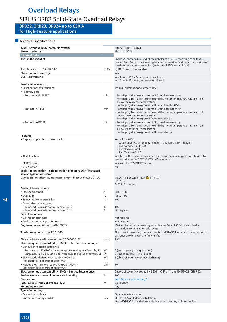
3RB22, 3RB23, 3RB24 up to 630 Afor High-Feature applications
Overload RelaysSIRIUS 3RB2 Solid-State Overload Relays3RB22, 3RB23, 3RB24 up to 630 Afor High-Feature applications
Technical specifications
Type – Overload relay: complete system Size of contactor
3RB22, 3RB23, 3RB24S00 ... S10/S12
General dataTrips in the event of Overload, phase failure and phase unbalance (> 40 % according to NEMA), +
ground fault (with corresponding function expansion module) and activation of the thermistor motor protection (with closed PTC sensor circuit)
Trip class acc. to IEC 60947-4-1 CLASS 5, 10, 20 and 30 adjustablePhase failure sensitivity YesOverload warning Yes, from 1.125 x Ie for symmetrical loads
and from 0.85 x Ie for unsymmetrical loadsReset and recovery• Reset options after tripping Manual, automatic and remote RESET• Recovery time - For automatic RESET min - For tripping due to overcurrent: 3 (stored permanently)
- For tripping by thermistor: time until the motor temperature has fallen 5 K below the response temperature
- For tripping due to a ground fault: no automatic RESET - For manual RESET min - For tripping due to overcurrent: 3 (stored permanently)
- For tripping by thermistor: time until the motor temperature has fallen 5 K below the response temperature
- For tripping due to a ground fault: Immediately - For remote RESET min - For tripping due to overcurrent: 3 (stored permanently)
- For tripping by thermistor: time until the motor temperature has fallen 5 K below the response temperature
- For tripping due to a ground fault: ImmediatelyFeatures• Display of operating state on device Yes, with 4 LEDs
- Green LED: “Ready” (3RB22, 3RB23), “DEVICE/IO-Link” (3RB24) - Red “Ground Fault” LED - Red “Thermistor” LED - Red “Overload” LED
• TEST function Yes, test of LEDs, electronics, auxiliary contacts and wiring of control circuit by pressing the button TEST/RESET / self-monitoring
• RESET button Yes, with the TEST/RESET button• STOP button NoExplosion protection – Safe operation of motors with “increased safety” type of protectionEC type test certificate number according to directive 94/9/EC (ATEX) 3RB22: PTB 05 ATEX 3022 II (2) GD
3RB23: --3RB24: On request
Ambient temperatures• Storage/transport °C -40 ... +80• Operation °C -25 ... +60• Temperature compensation °C +60• Permissible rated current - Temperature inside control cabinet 60 °C - Temperature inside control cabinet 70 °C
% %
100On request
Repeat terminals• Coil repeat terminals Not required• Auxiliary contact repeat terminal Not requiredDegree of protection acc. to IEC 60529 IP20 for the current measuring module sizes S6 and S10/S12 with busbar
connection in conjunction with coverTouch protection acc. to IEC 61140 The current measuring module sizes S6 and S10/S12 with busbar connection in
conjunction with cover are finger-safe.Shock resistance with sine acc. to IEC 60068-2-27 g/ms 15/11Electromagnetic compatibility (EMC) – Interference immunity• Conductor-related interference - Burst acc. to IEC 61000-4-4 (corresponds to degree of severity 3) - Surge acc. to IEC 61000-4-5 (corresponds to degree of severity 3)
kV kV
2 (power ports), 1 (signal ports)2 (line to earth), 1 (line to line)
• Electrostatic discharge acc. to IEC 61000-4-2 (corresponds to degree of severity 3)
kV 8 (air discharge), 6 (contact discharge)
• Field-related interference acc. to IEC 61000-4-3 (corresponds to degree of severity 3)
V/m 10
Electromagnetic compatibility (EMC) – Emitted interference Degree of severity A acc. to EN 55011 (CISPR 11) and EN 55022 (CISPR 22)Resistance to extreme climates – air humidity % 100Dimensions See “Dimensional drawings” Installation altitude above sea level m Up to 2000Mounting position AnyType of mounting• Evaluation modules Stand-alone installation• Current measuring module Size S00 to S3: Stand-alone installation,
S6 and S10/S12: stand-alone installation or mounting onto contactors
4/102
4
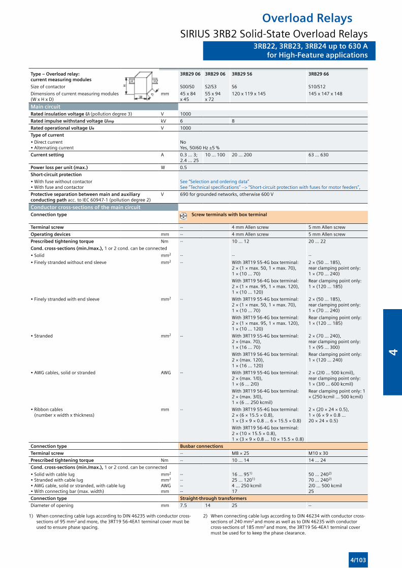
3RB22, 3RB23, 3RB24 up to 630 Afor High-Feature applications
Overload RelaysSIRIUS 3RB2 Solid-State Overload Relays
3RB22, 3RB23, 3RB24 up to 630 Afor High-Feature applications
Type – Overload relay: current measuring modules
3RB29 06 3RB29 06 3RB29 56 3RB29 66
Size of contactor S00/S0 S2/S3 S6 S10/S12
Dimensions of current measuring modules (W x H x D)
mm 45 x 84 x 45
55 x 94 x 72
120 x 119 x 145 145 x 147 x 148
Main circuitRated insulation voltage Ui (pollution degree 3) V 1000
Rated impulse withstand voltage Uimp kV 6 8
Rated operational voltage Ue V 1000
Type of current
• Direct current • Alternating current
NoYes, 50/60 Hz ±5 %
Current setting A 0.3 ... 3; 2.4 ... 25
10 ... 100 20 ... 200 63 ... 630
Power loss per unit (max.) W 0.5
Short-circuit protection
• With fuse without contactor • With fuse and contactor
See “Selection and ordering data”See “Technical specifications” --> “Short-circuit protection with fuses for motor feeders”,
Protective separation between main and auxiliary conducting path acc. to IEC 60947-1 (pollution degree 2)
V 690 for grounded networks, otherwise 600 V
Conductor cross-sections of the main circuitConnection type Screw terminals with box terminal
Terminal screw -- 4 mm Allen screw 5 mm Allen screw
Operating devices mm -- 4 mm Allen screw 5 mm Allen screw
Prescribed tightening torque Nm -- 10 ... 12 20 ... 22
Cond. cross-sections (min./max.), 1 or 2 cond. can be connected
• Solid mm2 -- -- --
• Finely stranded without end sleeve mm2 -- With 3RT19 55-4G box terminal: 2 × (1 × max. 50, 1 × max. 70), 1 × (10 ... 70)
2 × (50 ... 185), rear clamping point only: 1 × (70 ... 240)
With 3RT19 56-4G box terminal: 2 × (1 × max. 95, 1 × max. 120), 1 × (10 ... 120)
Rear clamping point only: 1 × (120 ... 185)
• Finely stranded with end sleeve mm2 -- With 3RT19 55-4G box terminal: 2 × (1 × max. 50, 1 × max. 70), 1 × (10 ... 70)
2 × (50 ... 185), rear clamping point only: 1 × (70 ... 240)
With 3RT19 56-4G box terminal: 2 × (1 × max. 95, 1 × max. 120), 1 × (10 ... 120)
Rear clamping point only: 1 × (120 ... 185)
• Stranded mm2 -- With 3RT19 55-4G box terminal: 2 × (max. 70), 1 × (16 ... 70)
2 × (70 ... 240), rear clamping point only: 1 × (95 ... 300)
With 3RT19 56-4G box terminal: 2 × (max. 120), 1 × (16 ... 120)
Rear clamping point only: 1 × (120 ... 240)
• AWG cables, solid or stranded AWG -- With 3RT19 55-4G box terminal: 2 × (max. 1/0), 1 × (6 ... 2/0)
2 × (2/0 ... 500 kcmil), rear clamping point only: 1 × (3/0 ... 600 kcmil)
With 3RT19 56-4G box terminal: 2 × (max. 3/0), 1 × (6 ... 250 kcmil)
Rear clamping point only: 1 × (250 kcmil ... 500 kcmil)
• Ribbon cables (number x width x thickness)
mm -- With 3RT19 55-4G box terminal: 2 × (6 × 15.5 × 0.8), 1 × (3 × 9 × 0.8 ... 6 × 15.5 × 0.8)
2 × (20 × 24 × 0.5), 1 × (6 × 9 × 0.8 ... 20 × 24 × 0.5)
With 3RT19 56-4G box terminal: 2 × (10 × 15.5 × 0.8), 1 × (3 × 9 × 0.8 ... 10 × 15.5 × 0.8)
Connection type Busbar connections
Terminal screw -- M8 × 25 M10 x 30
Prescribed tightening torque Nm -- 10 ... 14 14 ... 24
Cond. cross-sections (min./max.), 1 or 2 cond. can be connected
• Solid with cable lug • Stranded with cable lug • AWG cable, solid or stranded, with cable lug • With connecting bar (max. width)
mm2
mm2
AWG mm
-- -- -- --
16 ... 951)
25 ... 1201)
4 ... 250 kcmil 17
50 ... 2402)
70 ... 2402)
2/0 ... 500 kcmil25
Connection type Straight-through transformers
Diameter of opening mm 7.5 14 25 --
1) When connecting cable lugs according to DIN 46235 with conductor cross-sections of 95 mm2 and more, the 3RT19 56-4EA1 terminal cover must be used to ensure phase spacing.
2) When connecting cable lugs according to DIN 46234 with conductor cross-sections of 240 mm2 and more as well as to DIN 46235 with conductor cross-sections of 185 mm2 and more, the 3RT19 56-4EA1 terminal cover must be used for to keep the phase clearance.
4/103
4
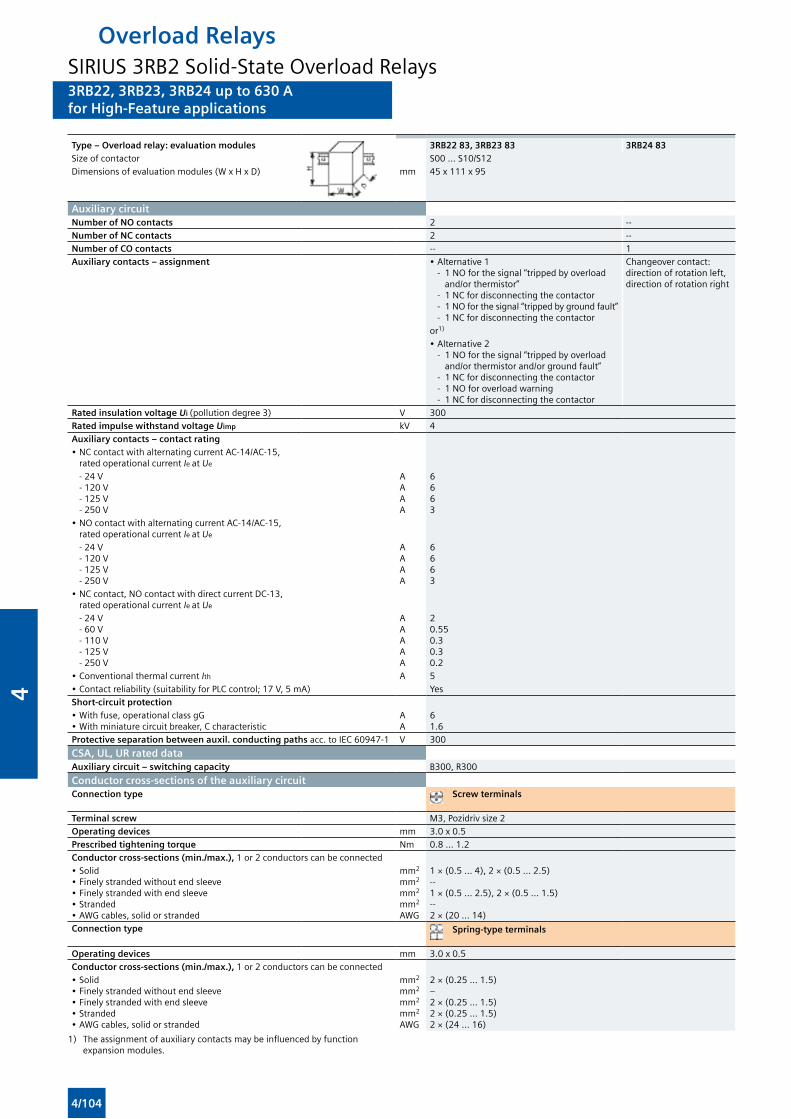
3RB22, 3RB23, 3RB24 up to 630 Afor High-Feature applications
Overload RelaysSIRIUS 3RB2 Solid-State Overload Relays3RB22, 3RB23, 3RB24 up to 630 Afor High-Feature applications
Type – Overload relay: evaluation modules 3RB22 83, 3RB23 83 3RB24 83Size of contactor S00 ... S10/S12Dimensions of evaluation modules (W x H x D) mm 45 x 111 x 95
Auxiliary circuitNumber of NO contacts 2 --Number of NC contacts 2 --Number of CO contacts -- 1Auxiliary contacts – assignment • Alternative 1
- 1 NO for the signal “tripped by overload and/or thermistor” - 1 NC for disconnecting the contactor - 1 NO for the signal “tripped by ground fault” - 1 NC for disconnecting the contactor
Changeover contact: direction of rotation left, direction of rotation right
or1)
• Alternative 2 - 1 NO for the signal “tripped by overload and/or thermistor and/or ground fault” - 1 NC for disconnecting the contactor - 1 NO for overload warning - 1 NC for disconnecting the contactor
Rated insulation voltage Ui (pollution degree 3) V 300Rated impulse withstand voltage Uimp kV 4Auxiliary contacts – contact rating• NC contact with alternating current AC-14/AC-15, rated operational current Ie at Ue
- 24 V - 120 V - 125 V - 250 V
A A A A
6663
• NO contact with alternating current AC-14/AC-15, rated operational current Ie at Ue
- 24 V - 120 V - 125 V - 250 V
A A A A
6663
• NC contact, NO contact with direct current DC-13, rated operational current Ie at Ue
- 24 V - 60 V - 110 V - 125 V - 250 V
A A A A A
20.550.30.30.2
• Conventional thermal current Ith A 5• Contact reliability (suitability for PLC control; 17 V, 5 mA) YesShort-circuit protection• With fuse, operational class gG • With miniature circuit breaker, C characteristic
A A
61.6
Protective separation between auxil. conducting paths acc. to IEC 60947-1 V 300
CSA, UL, UR rated dataAuxiliary circuit – switching capacity B300, R300
Conductor cross-sections of the auxiliary circuitConnection type Screw terminals
Terminal screw M3, Pozidriv size 2Operating devices mm 3.0 x 0.5Prescribed tightening torque Nm 0.8 ... 1.2Conductor cross-sections (min./max.), 1 or 2 conductors can be connected• Solid • Finely stranded without end sleeve • Finely stranded with end sleeve • Stranded • AWG cables, solid or stranded
mm2
mm2
mm2
mm2
AWG
1 × (0.5 ... 4), 2 × (0.5 ... 2.5)--1 × (0.5 ... 2.5), 2 × (0.5 ... 1.5)--2 × (20 ... 14)
Connection type Spring-type terminals
Operating devices mm 3.0 x 0.5Conductor cross-sections (min./max.), 1 or 2 conductors can be connected• Solid • Finely stranded without end sleeve • Finely stranded with end sleeve • Stranded • AWG cables, solid or stranded
mm2
mm2
mm2
mm2
AWG
2 × (0.25 ... 1.5)–2 × (0.25 ... 1.5)2 × (0.25 ... 1.5)2 × (24 ... 16)
1) The assignment of auxiliary contacts may be influenced by function expansion modules.
4/104
4
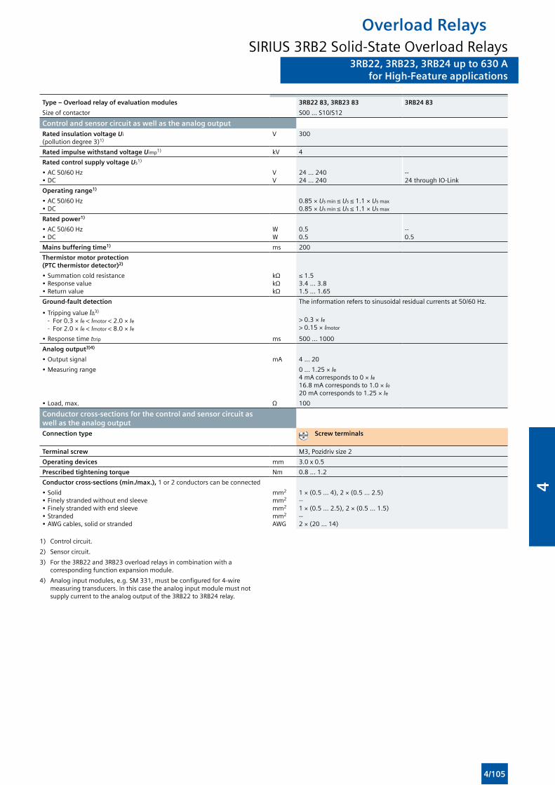
3RB22, 3RB23, 3RB24 up to 630 Afor High-Feature applications
Overload RelaysSIRIUS 3RB2 Solid-State Overload Relays
3RB22, 3RB23, 3RB24 up to 630 Afor High-Feature applications
Type – Overload relay of evaluation modules 3RB22 83, 3RB23 83 3RB24 83
Size of contactor S00 ... S10/S12
Control and sensor circuit as well as the analog outputRated insulation voltage Ui
(pollution degree 3)1)V 300
Rated impulse withstand voltage Uimp1) kV 4
Rated control supply voltage Us1)
• AC 50/60 Hz • DC
V V
24 ... 240 24 ... 240
--24 through IO-Link
Operating range1)
• AC 50/60 Hz • DC
0.85 × Us min ≤ Us ≤ 1.1 × Us max
0.85 × Us min ≤ Us ≤ 1.1 × Us max
Rated power1)
• AC 50/60 Hz • DC
W W
0.5 0.5
--0.5
Mains buffering time1) ms 200
Thermistor motor protection (PTC thermistor detector)2)
• Summation cold resistance • Response value • Return value
kΩ kΩ kΩ
≤ 1.53.4 ... 3.81.5 ... 1.65
Ground-fault detection The information refers to sinusoidal residual currents at 50/60 Hz.
• Tripping value IΔ3)
- For 0.3 × Ie < Imotor < 2.0 × Ie
- For 2.0 × Ie < Imotor < 8.0 × Ie
> 0.3 × Ie> 0.15 × Imotor
• Response time ttrip ms 500 ... 1000
Analog output3)4)
• Output signal mA 4 ... 20
• Measuring range 0 ... 1.25 × Ie4 mA corresponds to 0 × Ie16.8 mA corresponds to 1.0 × Ie20 mA corresponds to 1.25 × Ie
• Load, max. Ω 100
Conductor cross-sections for the control and sensor circuit as well as the analog outputConnection type Screw terminals
Terminal screw M3, Pozidriv size 2
Operating devices mm 3.0 x 0.5
Prescribed tightening torque Nm 0.8 ... 1.2
Conductor cross-sections (min./max.), 1 or 2 conductors can be connected
• Solid • Finely stranded without end sleeve • Finely stranded with end sleeve • Stranded • AWG cables, solid or stranded
mm2
mm2
mm2
mm2
AWG
1 × (0.5 ... 4), 2 × (0.5 ... 2.5)--1 × (0.5 ... 2.5), 2 × (0.5 ... 1.5)--2 × (20 ... 14)
1) Control circuit.
2) Sensor circuit.
3) For the 3RB22 and 3RB23 overload relays in combination with a corresponding function expansion module.
4) Analog input modules, e.g. SM 331, must be configured for 4-wire measuring transducers. In this case the analog input module must not supply current to the analog output of the 3RB22 to 3RB24 relay.
4/105
4
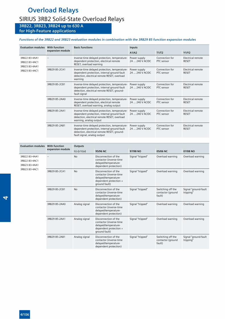
3RB22, 3RB23, 3RB24 up to 630 Afor High-Feature applications
Overload RelaysSIRIUS 3RB2 Solid-State Overload Relays3RB22, 3RB23, 3RB24 up to 630 Afor High-Feature applications
Functions of the 3RB22 and 3RB23 evaluation modules in combination with the 3RB29 85 function expansion modules
Evaluation modules With function expansion module
Basic functions Inputs
A1/A2 T1/T2 Y1/Y2
3RB22 83-4AA1
3RB22 83-4AC1
3RB23 83-4AA1
3RB23 83-4AC1
-- Inverse-time delayed protection, temperature-dependent protection, electrical remote RESET, overload warning
Power supply 24 ... 240 V AC/DC
Connection for PTC sensor
Electrical remote RESET
3RB29 85-2CA1 Inverse-time delayed protection, temperature-dependent protection, internal ground-fault detection, electrical remote RESET, overload warning
Power supply 24 ... 240 V AC/DC
Connection for PTC sensor
Electrical remote RESET
3RB29 85-2CB1 Inverse-time delayed protection, temperature-dependent protection, internal ground-fault detection, electrical remote RESET, ground-fault signal
Power supply 24 ... 240 V AC/DC
Connection for PTC sensor
Electrical remote RESET
3RB29 85-2AA0 Inverse-time delayed protection, temperature-dependent protection, electrical remote RESET, overload warning, analog output
Power supply 24 ... 240 V AC/DC
Connection for PTC sensor
Electrical remote RESET
3RB29 85-2AA1 Inverse-time delayed protection, temperature-dependent protection, internal ground-fault detection, electrical remote RESET, overload warning, analog output
Power supply 24 ... 240 V AC/DC
Connection for PTC sensor
Electrical remote RESET
3RB29 85-2AB1 Inverse-time delayed protection, temperature-dependent protection, internal ground-fault detection, electrical remote RESET, ground-fault signal, analog output
Power supply 24 ... 240 V AC/DC
Connection for PTC sensor
Electrical remote RESET
Evaluation modules With function expansion module
Outputs
I (–) / I (+) 95/96 NC 97/98 NO 05/06 NC 07/08 NO
3RB22 83-4AA1
3RB22 83-4AC1
3RB23 83-4AA1
3RB23 83-4AC1
-- No Disconnection of the contactor (inverse-time delayed/temperature-dependent protection)
Signal “tripped” Overload warning Overload warning
3RB29 85-2CA1 No Disconnection of the contactor (inverse-time delayed/temperature-dependent protection + ground fault)
Signal “tripped” Overload warning Overload warning
3RB29 85-2CB1 No Disconnection of the contactor (inverse-time delayed/temperature-dependent protection)
Signal “tripped” Switching off the contactor (ground fault)
Signal “ground-fault tripping”
3RB29 85-2AA0 Analog signal Disconnection of the contactor (inverse-time delayed/temperature-dependent protection)
Signal “tripped” Overload warning Overload warning
3RB29 85-2AA1 Analog signal Disconnection of the contactor (inverse-time delayed/temperature-dependent protection + ground fault)
Signal “tripped” Overload warning Overload warning
3RB29 85-2AB1 Analog signal Disconnection of the contactor (inverse-time delayed/temperature-dependent protection)
Signal “tripped” Switching off the contactor (ground fault)
Signal “ground-fault tripping”
4/106
4
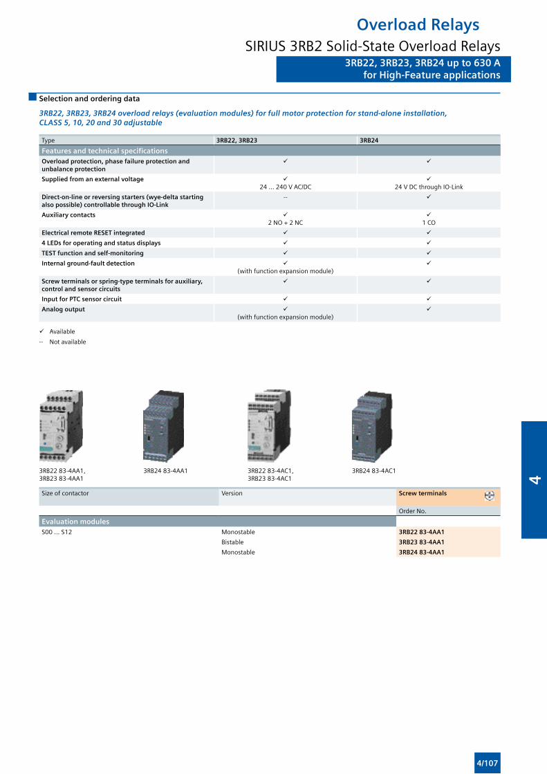
3RB22, 3RB23, 3RB24 up to 630 Afor High-Feature applications
Overload RelaysSIRIUS 3RB2 Solid-State Overload Relays
3RB22, 3RB23, 3RB24 up to 630 Afor High-Feature applications
Selection and ordering data
3RB22, 3RB23, 3RB24 overload relays (evaluation modules) for full motor protection for stand-alone installation, CLASS 5, 10, 20 and 30 adjustable
Type 3RB22, 3RB23 3RB24
Features and technical specificationsOverload protection, phase failure protection and unbalance protection
Supplied from an external voltage 24 ... 240 V AC/DC
24 V DC through IO-Link
Direct-on-line or reversing starters (wye-delta starting also possible) controllable through IO-Link
--
Auxiliary contacts 2 NO + 2 NC
1 CO
Electrical remote RESET integrated
4 LEDs for operating and status displays
TEST function and self-monitoring
Internal ground-fault detection (with function expansion module)
Screw terminals or spring-type terminals for auxiliary, control and sensor circuits
Input for PTC sensor circuit
Analog output (with function expansion module)
Available
-- Not available
3RB22 83-4AA1, 3RB24 83-4AA1 3RB22 83-4AC1, 3RB24 83-4AC1 3RB23 83-4AA1 3RB23 83-4AC1
Size of contactor Version Screw terminals
Order No.
Evaluation modulesS00 ... S12 Monostable 3RB22 83-4AA1
Bistable 3RB23 83-4AA1
Monostable 3RB24 83-4AA1
4/107
4
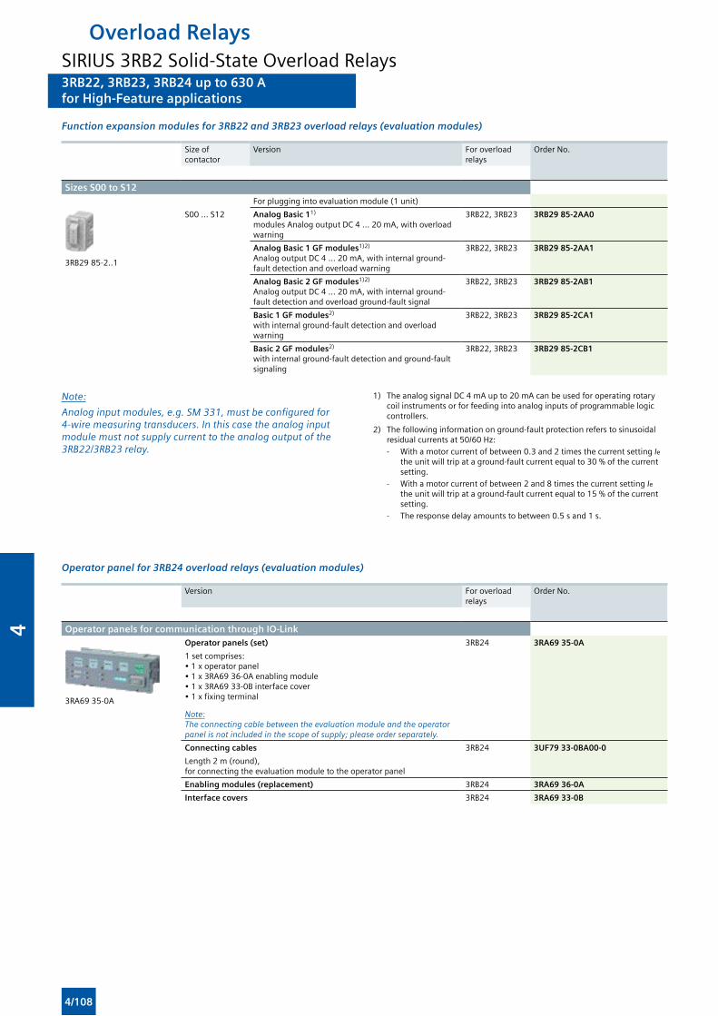
3RB22, 3RB23, 3RB24 up to 630 Afor High-Feature applications
Overload RelaysSIRIUS 3RB2 Solid-State Overload Relays3RB22, 3RB23, 3RB24 up to 630 Afor High-Feature applications
Function expansion modules for 3RB22 and 3RB23 overload relays (evaluation modules)
Size of contactor
Version For overload relays
Order No.
Sizes S00 to S12For plugging into evaluation module (1 unit)
3RB29 85-2..1
S00 ... S12 Analog Basic 11)
modules Analog output DC 4 ... 20 mA, with overload warning
3RB22, 3RB23 3RB29 85-2AA0
Analog Basic 1 GF modules1)2) Analog output DC 4 ... 20 mA, with internal ground-fault detection and overload warning
3RB22, 3RB23 3RB29 85-2AA1
Analog Basic 2 GF modules1)2) Analog output DC 4 ... 20 mA, with internal ground-fault detection and overload ground-fault signal
3RB22, 3RB23 3RB29 85-2AB1
Basic 1 GF modules2) with internal ground-fault detection and overload warning
3RB22, 3RB23 3RB29 85-2CA1
Basic 2 GF modules2) with internal ground-fault detection and ground-fault signaling
3RB22, 3RB23 3RB29 85-2CB1
Note:
Analoginputmodules,e.g.SM331,mustbeconfiguredfor4-wiremeasuringtransducers.Inthiscasetheanaloginputmodule must not supply current to the analog output of the 3RB22/3RB23relay.
1) The analog signal DC 4 mA up to 20 mA can be used for operating rotary coil instruments or for feeding into analog inputs of programmable logic controllers.
2) The following information on ground-fault protection refers to sinusoidal residual currents at 50/60 Hz:- With a motor current of between 0.3 and 2 times the current setting Ie
the unit will trip at a ground-fault current equal to 30 % of the current setting.
- With a motor current of between 2 and 8 times the current setting Ie
the unit will trip at a ground-fault current equal to 15 % of the current setting.
- The response delay amounts to between 0.5 s and 1 s.
Operator panel for 3RB24 overload relays (evaluation modules)
Version For overload relays
Order No.
Operator panels for communication through IO-Link
3RA69 35-0A
Operator panels (set) 3RB24 3RA69 35-0A
1 set comprises:• 1 x operator panel• 1 x 3RA69 36-0A enabling module• 1 x 3RA69 33-0B interface cover• 1 x fixing terminal
Note:Theconnectingcablebetweentheevaluationmoduleandtheoperatorpanel is not included in the scope of supply; please order separately.
Connecting cables 3RB24 3UF79 33-0BA00-0
Length 2 m (round), for connecting the evaluation module to the operator panel
Enabling modules (replacement) 3RB24 3RA69 36-0A
Interface covers 3RB24 3RA69 33-0B
4/108
4
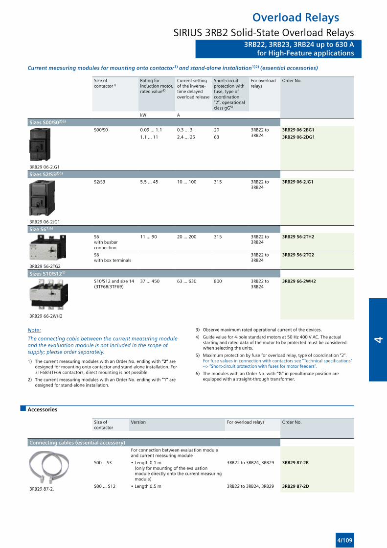
3RB22, 3RB23, 3RB24 up to 630 Afor High-Feature applications
Overload RelaysSIRIUS 3RB2 Solid-State Overload Relays
3RB22, 3RB23, 3RB24 up to 630 Afor High-Feature applications
Current measuring modules for mounting onto contactor1) and stand-alone installation1)2) (essential accessories)
Size of contactor3)
Rating for induction motor, rated value4)
Current setting of the inverse-time delayed overload release
Short-circuit protection with fuse, type of coordination “2”, operational class gG5)
For overload relays
Order No.
kW A
Sizes S00/S02)6)
3RB29 06-2.G1
S00/S0 0.09 … 1.1 0.3 … 3 20 3RB22 to 3RB24
3RB29 06-2BG1
1.1 … 11 2.4 … 25 63 3RB29 06-2DG1
Sizes S2/S32)6)
3RB29 06-2JG1
S2/S3 5.5 … 45 10 … 100 315 3RB22 to 3RB24
3RB29 06-2JG1
Size S61)6)
3RB29 56-2TG2
S6 with busbar connection
11 … 90 20 … 200 315 3RB22 to 3RB24
3RB29 56-2TH2
S6 with box terminals
3RB22 to 3RB24
3RB29 56-2TG2
Sizes S10/S121)
3RB29 66-2WH2
S10/S12 and size 14 (3TF68/3TF69)
37 … 450 63 … 630 800 3RB22 to 3RB24
3RB29 66-2WH2
Note:
Theconnectingcablebetweenthecurrentmeasuringmoduleandtheevaluationmoduleisnotincludedinthescopeofsupply; please order separately.
1) The current measuring modules with an Order No. ending with “2” are designed for mounting onto contactor and stand-alone installation. For 3TF68/3TF69 contactors, direct mounting is not possible.
2) The current measuring modules with an Order No. ending with “1” are designed for stand-alone installation.
3) Observe maximum rated operational current of the devices.
4) Guide value for 4-pole standard motors at 50 Hz 400 V AC. The actual starting and rated data of the motor to be protected must be considered when selecting the units.
5) Maximum protection by fuse for overload relay, type of coordination “2”. For fuse values in connection with contactors see “Technical specifications” --> “Short-circuit protection with fuses for motor feeders”,
6) The modules with an Order No. with “G” in penultimate position are equipped with a straight-through transformer.
Accessories
Size of contactor
Version For overload relays Order No.
Connecting cables (essential accessory)
3RB29 87-2.
For connection between evaluation module and current measuring module
S00 ...S3 • Length 0.1 m(only for mounting of the evaluation module directly onto the current measuring module)
3RB22 to 3RB24, 3RB29 3RB29 87-2B
S00 ... S12 • Length 0.5 m 3RB22 to 3RB24, 3RB29 3RB29 87-2D
4/109
4
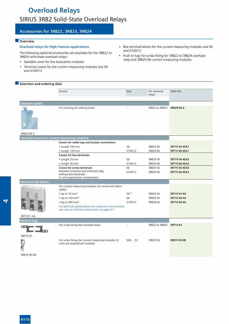
Accessories for 3RB22, 3RB23, 3RB24
Overload RelaysSIRIUS 3RB2 Solid-State Overload Relays
Accessories for 3RB22, 3RB23, 3RB24
Overview
Overload relays for High-Feature applications
The following optional accessories are available for the 3RB22 to 3RB24 solid-state overload relays:
• Sealable cover for the evaluation modules
• Terminal covers for the current measuring modules size S6 and S10/S12
• Box terminal blocks for the current measuring modules size S6 and S10/S12
• Push-in lugs for screw fixing for 3RB22 to 3RB24 overload relay and 3RB29 06 current measuring modules
Selection and ordering data
Version Size For overload relays
Order No.
Sealable covers
3RB29 84-2
For covering the setting knobs -- 3RB22 to 3RB24 3RB29 84-2
Terminal covers for current measuring modulesCovers for cable lugs and busbar connections
• Length 100 mm S6 3RB29 56 3RT19 56-4EA1
• Length 120 mm S10/S12 3RB29 66 3RT19 66-4EA1
Covers for box terminals
• Length 25 mm S6 3RB29 56 3RT19 56-4EA2
• Length 30 mm S10/S12 3RB29 66 3RT19 66-4EA2
Covers for screw terminals between contactor and overload relay, without box terminals (1 unit required per combination)
S6 3RB29 56 3RT19 56-4EA3
S10/S12 3RB29 66 3RT19 66-4EA3
Box terminal blocks
3RT19 5.-4G
For current measuring modules, for round and ribbon cables
• Up to 70 mm2 S61) 3RB29 56 3RT19 55-4G
• Up to 120 mm2 S6 3RB29 56 3RT19 56-4G
• Up to 240 mm2 S10/S12 3RB29 66 3RT19 66-4G
For technical specifications for conductor cross-sections see note on Technical Information on page 4/1.
Push-in lugs
3RP19 03
For screw fixing the overload relays -- 3RB22 to 3RB24 3RP19 03
3RB19 00-0B
For screw fixing the current measuring modules (2 units are required per module)
S00 ... S3 3RB29 06 3RB19 00-0B
4/110
4
Load Feeders and MotorStarters for Use in theControl Cabinet
5/2 Introduction
SIRIUS 3RA6 Compact Starters
5/3 General data
3RA61, 3RA62 Compact Starters
5/11 3RA61 direct-on-line starters
5/12 3RA62 reversing starters
3RA64, 3RA65 Compact Starters for IO-Link
5/13 3RA64 direct-on-line starters
5/14 3RA65 reversing starters
5/15 Accessories
5/20 Add-on modules for AS-Interface
5/22 Infeed systems for 3RA6
5
5
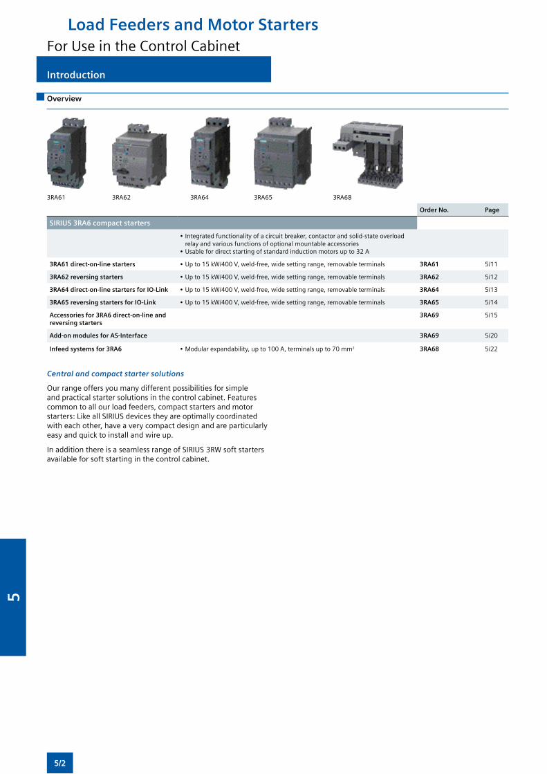
Load Feeders and Motor StartersFor Use in the Control Cabinet
Introduction
3RA61 3RA62 3RA64 3RA65 3RA68
Order No. Page
SIRIUS 3RA6 compact starters
•Integratedfunctionalityofacircuitbreaker,contactorandsolid-stateoverloadrelay and various functions of optional mountable accessories
•Usablefordirectstartingofstandardinductionmotorsupto32A
3RA61 direct-on-line starters •Upto15kW/400V,weld-free,widesettingrange,removableterminals 3RA61 5/11
3RA62 reversing starters •Upto15kW/400V,weld-free,widesettingrange,removableterminals 3RA62 5/12
3RA64 direct-on-line starters for IO-Link •Upto15kW/400V,weld-free,widesettingrange,removableterminals 3RA64 5/13
3RA65 reversing starters for IO-Link •Upto15kW/400V,weld-free,widesettingrange,removableterminals 3RA65 5/14
Accessories for 3RA6 direct-on-line and reversing starters
3RA69 5/15
Add-on modules for AS-Interface 3RA69 5/20
Infeed systems for 3RA6 •Modularexpandability,upto100A,terminalsupto70mm2 3RA68 5/22
Central and compact starter solutions
Overview
Our range offers you many different possibilities for simple and practical starter solutions in the control cabinet. Features common to all our load feeders, compact starters and motor starters: Like all SIRIUS devices they are optimally coordinated witheachother,haveaverycompactdesignandareparticularlyeasyandquicktoinstallandwireup.
InadditionthereisaseamlessrangeofSIRIUS3RWsoftstartersavailable for soft starting in the control cabinet.
5/2
5
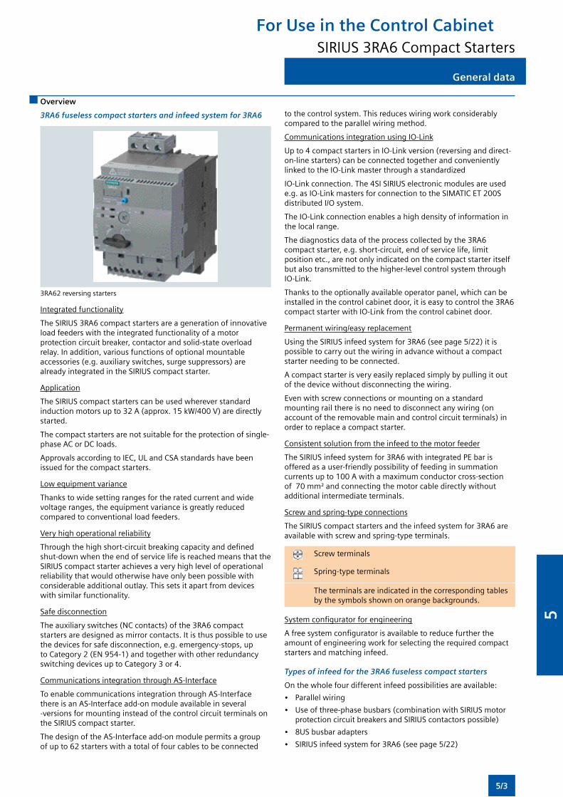
For Use in the Control CabinetSIRIUS 3RA6 Compact Starters
General data
Overview
3RA6 fuseless compact starters and infeed system for 3RA6
3RA62 reversing starters
Integrated functionality
The SIRIUS 3RA6 compact starters are a generation of innovative loadfeederswiththeintegratedfunctionalityofamotorprotection circuit breaker, contactor and solid-state overload relay. In addition, various functions of optional mountable accessories(e.g.auxiliaryswitches,surgesuppressors)arealready integrated in the SIRIUS compact starter.
Application
TheSIRIUScompactstarterscanbeusedwhereverstandardinductionmotorsupto32A(approx.15kW/400V)aredirectlystarted.
The compact starters are not suitable for the protection of single-phase AC or DC loads.
Approvals according to IEC, UL and CSA standards have been issued for the compact starters.
Lowequipmentvariance
Thankstowidesettingrangesfortheratedcurrentandwidevoltage ranges, the equipment variance is greatly reduced compared to conventional load feeders.
Veryhighoperationalreliability
Throughthehighshort-circuitbreakingcapacityanddefinedshut-downwhentheendofservicelifeisreachedmeansthattheSIRIUS compact starter achieves a very high level of operational reliabilitythatwouldotherwisehaveonlybeenpossiblewithconsiderable additional outlay. This sets it apart from devices withsimilarfunctionality.
Safe disconnection
Theauxiliaryswitches(NCcontacts)ofthe3RA6compactstarters are designed as mirror contacts. It is thus possible to use the devices for safe disconnection, e.g. emergency-stops, up toCategory2(EN954-1)andtogetherwithotherredundancyswitchingdevicesuptoCategory3or4.
Communications integration through AS-Interface
To enable communications integration through AS-Interface there is an AS-Interface add-on module available in several -versions for mounting instead of the control circuit terminals on the SIRIUS compact starter.
The design of the AS-Interface add-on module permits a group ofupto62starterswithatotaloffourcablestobeconnected
tothecontrolsystem.Thisreduceswiringworkconsiderablycomparedtotheparallelwiringmethod.
Communications integration using IO-Link
Up to 4 compact starters in IO-Link version (reversing and direct-on-linestarters)canbeconnectedtogetherandconvenientlylinked to the IO-Link master through a standardized
IO-Link connection. The 4SI SIRIUS electronic modules are used e.g.asIO-LinkmastersforconnectiontotheSIMATICET200Sdistributed I/O system.
The IO-Link connection enables a high density of information in the local range.
The diagnostics data of the process collected by the 3RA6 compact starter, e.g. short-circuit, end of service life, limit position etc., are not only indicated on the compact starter itself but also transmitted to the higher-level control system through IO-Link.
Thankstotheoptionallyavailableoperatorpanel,whichcanbeinstalled in the control cabinet door, it is easy to control the 3RA6 compactstarterwithIO-Linkfromthecontrolcabinetdoor.
Permanentwiring/easyreplacement
UsingtheSIRIUSinfeedsystemfor3RA6(seepage5/22)itispossibletocarryoutthewiringinadvancewithoutacompactstarter needing to be connected.
A compact starter is very easily replaced simply by pulling it out ofthedevicewithoutdisconnectingthewiring.
Evenwithscrewconnectionsormountingonastandardmountingrailthereisnoneedtodisconnectanywiring(onaccountoftheremovablemainandcontrolcircuitterminals)inorder to replace a compact starter.
Consistent solution from the infeed to the motor feeder
TheSIRIUSinfeedsystemfor3RA6withintegratedPEbarisoffered as a user-friendly possibility of feeding in summation currentsupto100Awithamaximumconductorcross-sectionof70mm²andconnectingthemotorcabledirectlywithoutadditional intermediate terminals.
Screwandspring-typeconnections
The SIRIUS compact starters and the infeed system for 3RA6 are availablewithscrewandspring-typeterminals.
Screwterminals
Spring-type terminals
The terminals are indicated in the corresponding tables bythesymbolsshownonorangebackgrounds.
Systemconfiguratorforengineering
Afreesystemconfiguratorisavailabletoreducefurthertheamountofengineeringworkforselectingtherequiredcompactstarters and matching infeed.
Types of infeed for the 3RA6 fuseless compact starters
Onthewholefourdifferentinfeedpossibilitiesareavailable:
• Parallelwiring
• Useofthree-phasebusbars(combinationwithSIRIUSmotorprotectioncircuitbreakersandSIRIUScontactorspossible)
• 8US busbar adapters
• SIRIUSinfeedsystemfor3RA6(seepage5/22)
5/3
5
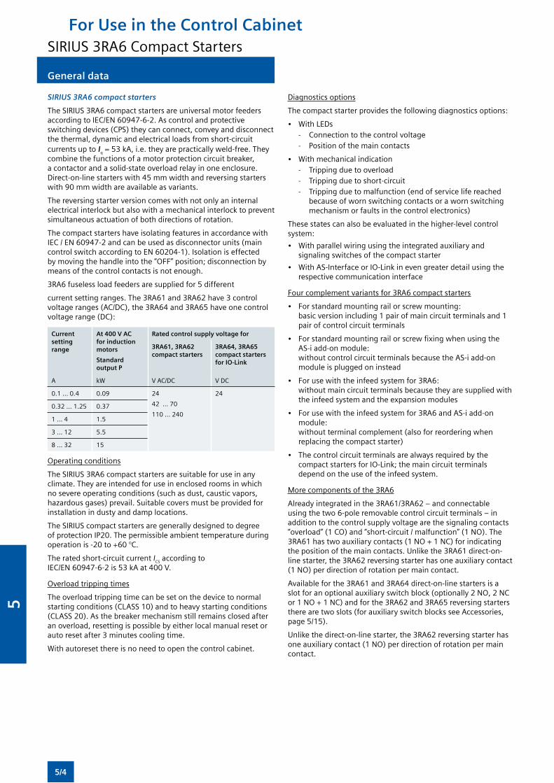
For Use in the Control CabinetSIRIUS 3RA6 Compact Starters
General data
SIRIUS 3RA6 compact starters
The SIRIUS 3RA6 compact starters are universal motor feeders accordingtoIEC/EN60947-6-2.Ascontrolandprotectiveswitchingdevices(CPS)theycanconnect,conveyanddisconnectthe thermal, dynamic and electrical loads from short-circuit currents up to Iq=53kA,i.e.theyarepracticallyweld-free.Theycombine the functions of a motor protection circuit breaker, a contactor and a solid-state overload relay in one enclosure. Direct-on-linestarterswith45mmwidthandreversingstarterswith90mmwidthareavailableasvariants.
Thereversingstarterversioncomeswithnotonlyaninternalelectricalinterlockbutalsowithamechanicalinterlocktopreventsimultaneous actuation of both directions of rotation.
ThecompactstartershaveisolatingfeaturesinaccordancewithIEC/EN60947-2andcanbeusedasdisconnectorunits(maincontrolswitchaccordingtoEN60204-1).Isolationiseffectedby moving the handle into the “OFF” position; disconnection by means of the control contacts is not enough.
3RA6 fuseless load feeders are supplied for 5 different
current setting ranges. The 3RA61 and 3RA62 have 3 control voltageranges(AC/DC),the3RA64and3RA65haveonecontrolvoltagerange(DC):
Current setting range
At 400 V AC for induction motors
Standard output P
Rated control supply voltage for
3RA61, 3RA62 compact starters
3RA64, 3RA65 compact starters for IO-Link
A kW VAC/DC VDC
0.1 ... 0.4 0.09 24
42...70
110 ... 240
24
0.32 ... 1.25 0.37
1 ... 4 1.5
3 ... 12 5.5
8 ... 32 15
Operating conditions
The SIRIUS 3RA6 compact starters are suitable for use in any climate.Theyareintendedforuseinenclosedroomsinwhichno severe operating conditions (such as dust, caustic vapors, hazardousgases)prevail.Suitablecoversmustbeprovidedforinstallation in dusty and damp locations.
The SIRIUS compact starters are generally designed to degree of protection IP20. The permissible ambient temperature during operation is -20 to +60 °C.
The rated short-circuit current ICS according to IEC/EN60947-6-2is53kAat400V.
Overload tripping times
The overload tripping time can be set on the device to normal startingconditions(CLASS10)andtoheavystartingconditions(CLASS20).Asthebreakermechanismstillremainsclosedafteran overload, resetting is possible by either local manual reset or auto reset after 3 minutes cooling time.
Withautoresetthereisnoneedtoopenthecontrolcabinet.
Diagnostics options
Thecompactstarterprovidesthefollowingdiagnosticsoptions:
• WithLEDs - Connection to the control voltage - Position of the main contacts
• Withmechanicalindication- Tripping due to overload- Tripping due to short-circuit- Tripping due to malfunction (end of service life reached
becauseofwornswitchingcontactsorawornswitchingmechanismorfaultsinthecontrolelectronics)
These states can also be evaluated in the higher-level control system:
• Withparallelwiringusingtheintegratedauxiliaryandsignalingswitchesofthecompactstarter
• WithAS-InterfaceorIO-Linkinevengreaterdetailusingtherespective communication interface
Four complement variants for 3RA6 compact starters
• Forstandardmountingrailorscrewmounting: basic version including 1 pair of main circuit terminals and 1 pair of control circuit terminals
• ForstandardmountingrailorscrewfixingwhenusingtheAS-i add-on module: withoutcontrolcircuitterminalsbecausetheAS-iadd-onmodule is plugged on instead
• Forusewiththeinfeedsystemfor3RA6: withoutmaincircuitterminalsbecausetheyaresuppliedwiththeinfeedsystemandtheexpansionmodules
• Forusewiththeinfeedsystemfor3RA6andAS-iadd-onmodule: withoutterminalcomplement(alsoforreorderingwhenreplacingthecompactstarter)
• Thecontrolcircuitterminalsarealwaysrequiredbythecompact starters for IO-Link; the main circuit terminals depend on the use of the infeed system.
Morecomponentsofthe3RA6
Already integrated in the 3RA61/3RA62 – and connectable usingthetwo6-poleremovablecontrolcircuitterminals–inaddition to the control supply voltage are the signaling contacts “overload”(1CO)and“short-circuit/malfunction”(1NO).The3RA61hastwoauxiliarycontacts(1NO+1NC)forindicatingthe position of the main contacts. Unlike the 3RA61 direct-on-linestarter,the3RA62reversingstarterhasoneauxiliarycontact(1NO)perdirectionofrotationpermaincontact.
Available for the 3RA61 and 3RA64 direct-on-line starters is a slotforanoptionalauxiliaryswitchblock(optionally2NO,2NCor1NO+1NC)andforthe3RA62and3RA65reversingstarterstherearetwoslots(forauxiliaryswitchblocksseeAccessories,page5/15).
Unlike the direct-on-line starter, the 3RA62 reversing starter has oneauxiliarycontact(1NO)perdirectionofrotationpermaincontact.
5/4
5
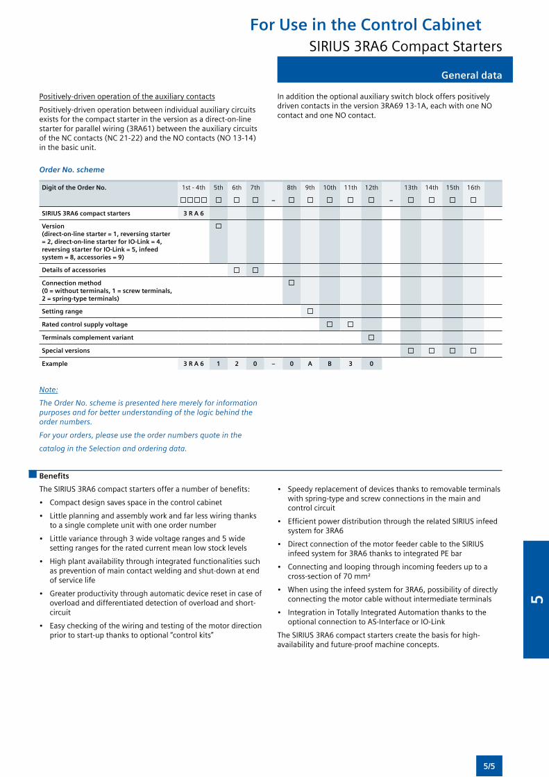
For Use in the Control CabinetSIRIUS 3RA6 Compact Starters
General data
Positively-drivenoperationoftheauxiliarycontacts
Positively-drivenoperationbetweenindividualauxiliarycircuitsexistsforthecompactstarterintheversionasadirect-on-linestarterforparallelwiring(3RA61)betweentheauxiliarycircuitsoftheNCcontacts(NC21-22)andtheNOcontacts(NO13-14)in the basic unit.
Inadditiontheoptionalauxiliaryswitchblockofferspositivelydrivencontactsintheversion3RA6913-1A,eachwithoneNOcontactandoneNOcontact.
Order No. scheme
Digit of the Order No. 1st - 4th 5th 6th 7th 8th 9th 10th 11th 12th 13th 14th 15th 16th
– –
SIRIUS 3RA6 compact starters 3 R A 6
Version (direct-on-line starter = 1, reversing starter = 2, direct-on-line starter for IO-Link = 4, reversing starter for IO-Link = 5, infeed system = 8, accessories = 9)
Details of accessories
Connection method (0 = without terminals, 1 = screw terminals, 2 = spring-type terminals)
Setting range
Rated control supply voltage
Terminals complement variant
Special versions
Example 3 R A 6 1 2 0 – 0 A B 3 0
Note:
The Order No. scheme is presented here merely for information purposes and for better understanding of the logic behind the order numbers.
For your orders, please use the order numbers quote in the
catalog in the Selection and ordering data.
Benefits
TheSIRIUS3RA6compactstartersofferanumberofbenefits:
• Compact design saves space in the control cabinet
• Littleplanningandassemblyworkandfarlesswiringthankstoasinglecompleteunitwithoneordernumber
• Littlevariancethrough3widevoltagerangesand5widesettingrangesfortheratedcurrentmeanlowstocklevels
• High plant availability through integrated functionalities such aspreventionofmaincontactweldingandshut-downatendof service life
• Greater productivity through automatic device reset in case of overload and differentiated detection of overload and short-circuit
• Easycheckingofthewiringandtestingofthemotordirectionprior to start-up thanks to optional “control kits”
• Speedy replacement of devices thanks to removable terminals withspring-typeandscrewconnectionsinthemainandcontrol circuit
• EfficientpowerdistributionthroughtherelatedSIRIUSinfeedsystem for 3RA6
• Direct connection of the motor feeder cable to the SIRIUS infeed system for 3RA6 thanks to integrated PE bar
• Connecting and looping through incoming feeders up to a cross-sectionof70mm²
• Whenusingtheinfeedsystemfor3RA6,possibilityofdirectlyconnectingthemotorcablewithoutintermediateterminals
• Integration in Totally Integrated Automation thanks to the optional connection to AS-Interface or IO-Link
The SIRIUS 3RA6 compact starters create the basis for high-availability and future-proof machine concepts.
5/5
5
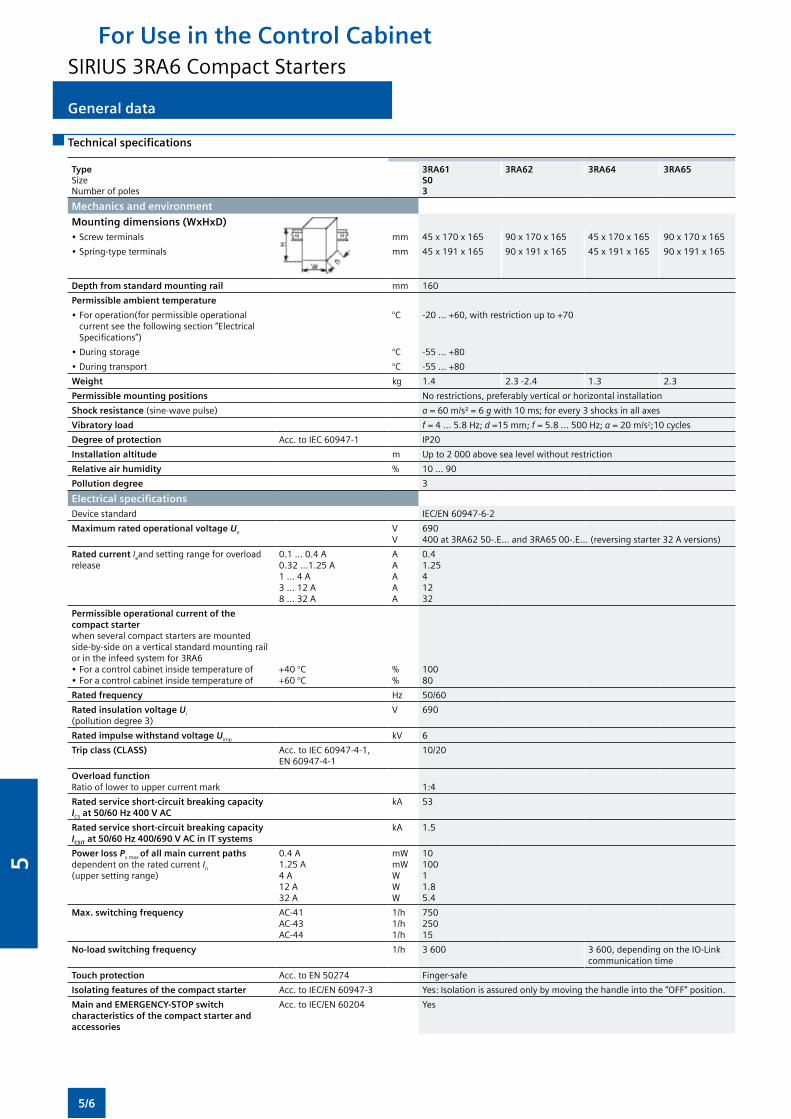
General data
Technical specifications
Type 3RA61 3RA62 3RA64 3RA65Size S0Numberofpoles 3
Mechanics and environment
Mounting dimensions (WxHxD) •Screwterminals mm 45x170x165 90x170x165 45x170x165 90x170x165
•Spring-typeterminals mm 45x191x165 90x191x165 45x191x165 90x191x165
Depth from standard mounting rail mm 160
Permissible ambient temperature
•Foroperation(forpermissibleoperationalcurrentseethefollowingsection“ElectricalSpecifications”)
°C -20...+60,withrestrictionupto+70
•Duringstorage °C -55 ... +80
•Duringtransport °C -55 ... +80
Weight kg 1.4 2.3 -2.4 1.3 2.3
Permissible mounting positions Norestrictions,preferablyverticalorhorizontalinstallation
Shock resistance(sine-wavepulse) a =60m/s²=6 g with10ms;forevery3shocksinallaxes
Vibratory load f = 4 ... 5.8 Hz; d =15 mm; f = 5.8 ... 500 Hz; a = 20 m/s2;10 cycles
Degree of protection Acc.toIEC60947-1 IP20
Installation altitude m Upto2000abovesealevelwithoutrestriction
Relative air humidity % 10...90
Pollution degree 3
Electrical specifications
Device standard IEC/EN60947-6-2
Maximum rated operational voltage Ue VV
690400at3RA6250-.E...and3RA6500-.E...(reversingstarter32Aversions)
Rated current Ieand setting range for overload release
0.1 ... 0.4 A0.32 ...1.25 A1 ... 4 A3 ... 12 A8 ... 32 A
AAAAA
0.4 1.25 4 12 32
Permissible operational current of the compact starterwhenseveralcompactstartersaremountedside-by-side on a vertical standard mounting rail or in the infeed system for 3RA6•Foracontrolcabinetinsidetemperatureof•Foracontrolcabinetinsidetemperatureof
+40 °C+60 °C
%%
10080
Rated frequency Hz 50/60
Rated insulation voltage Ui (pollutiondegree3)
V 690
Rated impulse withstand voltage Uimp kV 6
Trip class (CLASS) Acc.toIEC60947-4-1, EN60947-4-1
10/20
Overload functionRatiooflowertouppercurrentmark 1:4
Rated service short-circuit breaking capacity ICS at 50/60 Hz 400 V AC
kA 53
Rated service short-circuit breaking capacity ICSIT at 50/60 Hz 400/690 V AC in IT systems
kA 1.5
Power loss Pvmaxof all main current paths dependent on the rated current In
(uppersettingrange)
0.4 A1.25 A4 A12 A32 A
mWmWWWW
1010011.85.4
Max. switching frequency AC-41AC-43AC-44
1/h1/h1/h
75025015
No-load switching frequency 1/h 3 600 3 600, depending on the IO-Link communication time
Touch protection Acc.toEN50274 Finger-safe
Isolating features of the compact starter Acc.toIEC/EN60947-3 Yes: Isolation is assured only by moving the handle into the “OFF” position.
Main and EMERGENCY-STOP switch characteristics of the compact starter and accessories
Acc.toIEC/EN60204 Yes
For Use in the Control CabinetSIRIUS 3RA6 Compact Starters
5/6
5
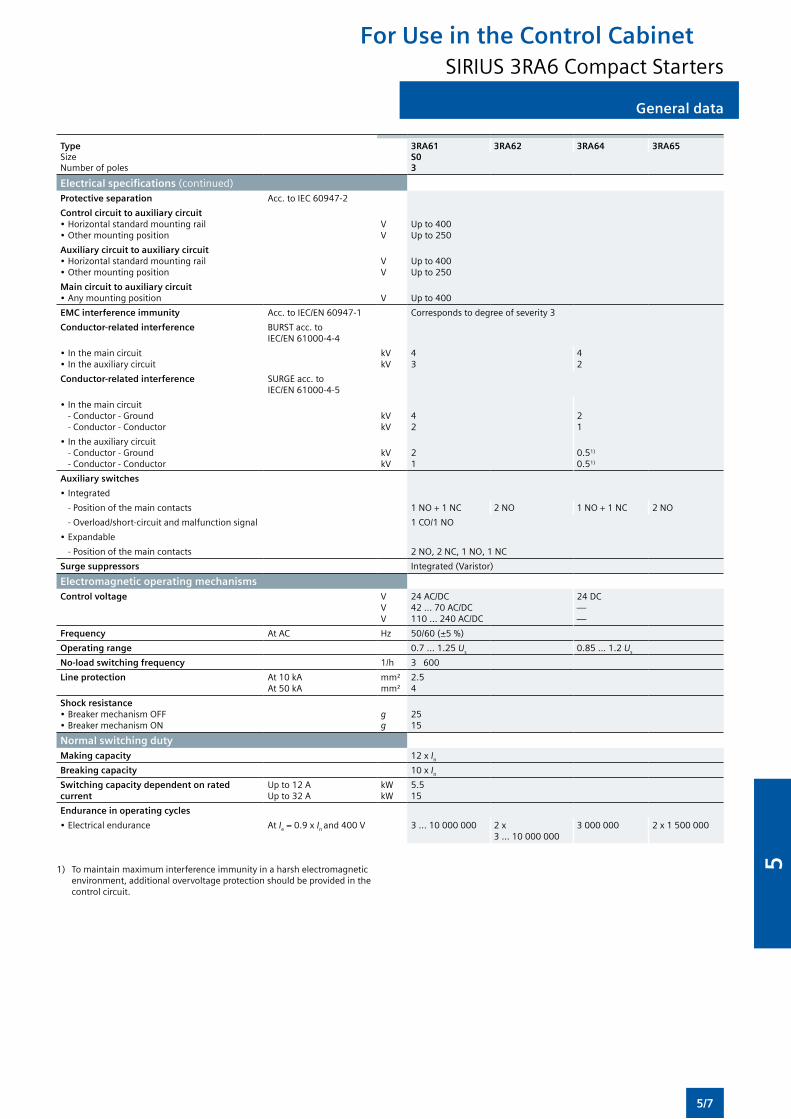
General data
Type 3RA61 3RA62 3RA64 3RA65Size S0Numberofpoles 3
Electrical specifications (continued)Protective separation Acc.toIEC60947-2
Control circuit to auxiliary circuit•Horizontalstandardmountingrail•Othermountingposition
VV
Up to 400Up to 250
Auxiliary circuit to auxiliary circuit•Horizontalstandardmountingrail•Othermountingposition
VV
Up to 400Up to 250
Main circuit to auxiliary circuit•Anymountingposition V Up to 400
EMC interference immunity Acc.toIEC/EN60947-1 Corresponds to degree of severity 3
Conductor-related interference BURST acc. to IEC/EN61000-4-4
•Inthemaincircuit•Intheauxiliarycircuit
kVkV
43
42
Conductor-related interference SURGE acc. to IEC/EN61000-4-5
•Inthemaincircuit - Conductor - Ground - Conductor - Conductor
kVkV
42
21
•Intheauxiliarycircuit - Conductor - Ground - Conductor - Conductor
kVkV
2 1
0.51)
0.51)
Auxiliary switches
•Integrated
- Position of the main contacts 1NO+1NC 2NO 1NO+1NC 2NO
- Overload/short-circuit and malfunction signal 1CO/1NO
•Expandable
- Position of the main contacts 2NO,2NC,1NO,1NC
Surge suppressors Integrated(Varistor)
Electromagnetic operating mechanisms
Control voltage VVV
24 AC/DC42...70AC/DC110 ... 240 AC/DC
24 DC——
Frequency At AC Hz 50/60(±5%)
Operating range 0.7...1.25Us 0.85 ... 1.2 Us
No-load switching frequency 1/h 3 600
Line protection At 10 kAAt 50 kA
mm²mm²
2.5 4
Shock resistance•BreakermechanismOFF•BreakermechanismON
gg
2515
Normal switching dutyMaking capacity 12xIn
Breaking capacity 10xIn
Switching capacity dependent on rated current
Up to 12 AUp to 32 A
kWkW
5.515
Endurance in operating cycles
•Electricalendurance At Ie=0.9xIn and400V 3 ... 10 000 000 2x3 ... 10 000 000
3 000 000 2x1500000
1) Tomaintainmaximuminterferenceimmunityinaharshelectromagneticenvironment, additional overvoltage protection should be provided in the control circuit.
For Use in the Control CabinetSIRIUS 3RA6 Compact Starters
5/7
5
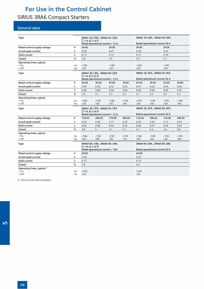
General data
Type 3RA61 20-. B3., 3RA62 50-. B3. = A, B, C or D
Rated operational current ≤ 12 A
3RA61 20-.EB3., 3RA62 50-.EB3.
Rated operational current 32 A
Rated control supply voltage V 24 AC 24 DC 24 AC 24 DC
Inrush peak current A 0.59 0.47 0.59 0.47
Hold current A 0.13 0.12 0.17 0.14
Closed W 2.8 2.9 3.5 3.1
Operating times, typical•On•Off
msms
<160<35
<140<35
<160<30
<140<30
Type 3RA61 20-. E3., 3RA62 50-. E3. = A, B, C or D
Rated operational current ≤ 12 A
3RA61 20-.EE3., 3RA62 50-.EE3.
Rated operational current 32 A
Rated control supply voltage V 42 AC 70 AC 42 DC 70 DC 42 AC 70 AC 42 DC 70 DC
Inrush peak current A 0.44 0.50 0.32 0.53 0.47 0.63 0.34 0.56
Hold current A 0.08 0.08 0.06 0.04 0.09 0.08 0.09 0.07
Closed W 2.6 3.1 2.2 2.2 2.7 3.2 3.6 4.2
Operating times, typical•On•Off
msms
<160<35
<140<50
<160<35
<140<40
<150<30
<140<40
<150<30
<140<40
Type 3RA61 20-. P3., 3RA62 50-. P3. = A, B, C or D
Rated operational current ≤ 12 A
3RA61 20-.EP3., 3RA62 50-.EP3.
Rated operational current 32 A
Rated control supply voltage V 110 AC 240 AC 110 DC 240 DC 110 AC 240 AC 110 DC 240 DC
Inrush peak current A 0.24 0.40 0.17 0.29 0.24 0.40 0.17 0.29
Hold current A 0.06 0.08 0.03 0.02 0.06 0.07 0.04 0.03
Closed W 3.8 6 3.1 5.1 3.7 5.2 3.4 5.8
Operating times, typical•On•Off
msms
<160<50
<140<80
<150<50
<140<70
<160<40
<140<60
<150<40
<140<60
Type 3RA64 00-.@B4., 3RA65 00-.@B4.@ = A, B, C or DRated operational current ≤ 12A
3RA64 00-.EB4., 3RA65 00-.EB4.
Rated operational current 32 A
Rated control supply voltage V 24 DC 24 DC
Inrush peak current A 0.39 0.53
Hold current A 0.13 0.15
Closed W 2.9 3.4
Operating times, typical1)
•On•Off
msms
<140<35
<140<30
1) PlusIO-Linkcommunication.
For Use in the Control CabinetSIRIUS 3RA6 Compact Starters
5/8
5
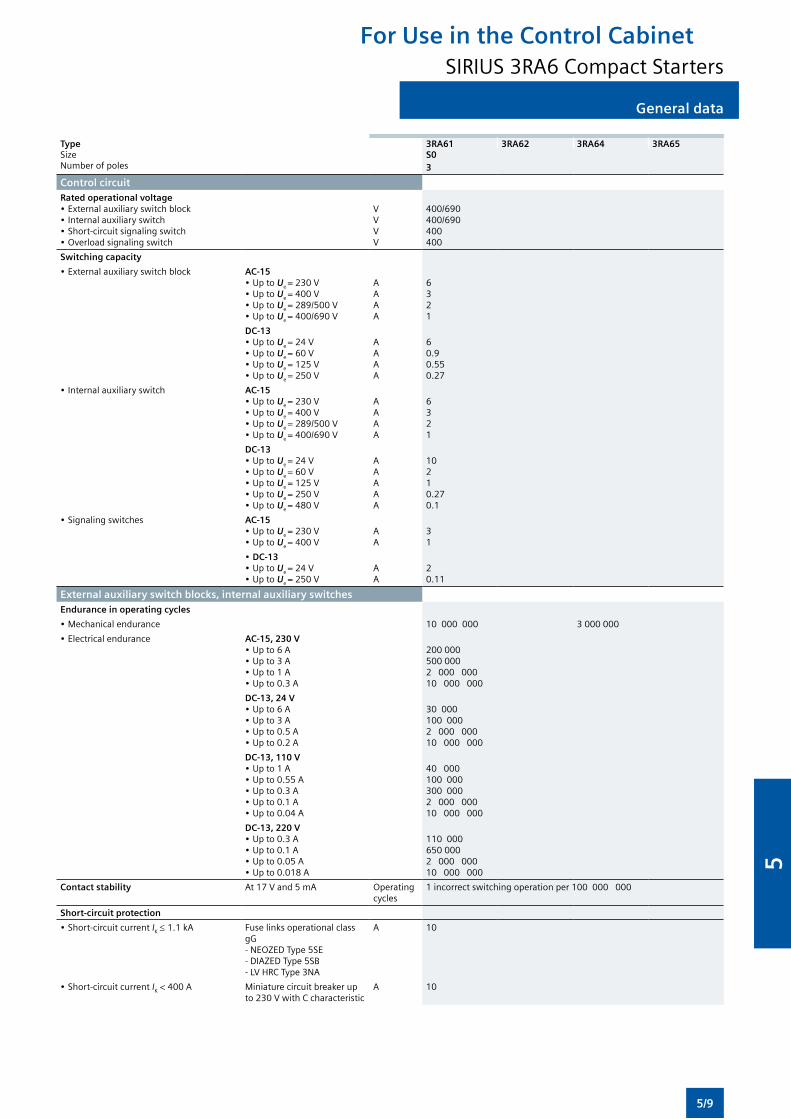
General data
Type 3RA61 3RA62 3RA64 3RA65Size S0Numberofpoles 3
Control circuitRated operational voltage •Externalauxiliaryswitchblock•Internalauxiliaryswitch•Short-circuitsignalingswitch•Overloadsignalingswitch
VVVV
400/690400/690400400
Switching capacity
•Externalauxiliaryswitchblock AC-15•UptoUe =230V•UptoUe =400V•UptoUe =289/500V•UptoUe =400/690V
AAAA
6321
DC-13•UptoUe =24V•UptoUe =60V•UptoUe =125V•UptoUe =250V
AAAA
60.90.550.27
•Internalauxiliaryswitch AC-15•UptoUe =230V•UptoUe =400V•UptoUe =289/500V•UptoUe =400/690V
AAAA
6321
DC-13•UptoUe =24V•UptoUe =60V•UptoUe =125V•UptoUe =250V•UptoUe =480V
AAAAA
10210.270.1
•Signalingswitches AC-15•UptoUe =230V•UptoUe =400V
AA
31
•DC-13•UptoUe =24V•UptoUe =250V
AA
20.11
External auxiliary switch blocks, internal auxiliary switchesEndurance in operating cycles
•Mechanicalendurance 10 000 000 3 000 000
•Electricalendurance AC-15, 230 V•Upto6A•Upto3A•Upto1A•Upto0.3A
200 000500 0002 000 00010 000 000
DC-13, 24 V•Upto6A•Upto3A•Upto0.5A•Upto0.2A
30 000100 0002 000 00010 000 000
DC-13, 110 V•Upto1A•Upto0.55A•Upto0.3A•Upto0.1A•Upto0.04A
40 000100 000300 0002 000 00010 000 000
DC-13, 220 V•Upto0.3A•Upto0.1A•Upto0.05A•Upto0.018A
110 000650 0002 000 00010 000 000
Contact stability At17Vand5mA Operating cycles
1incorrectswitchingoperationper100000000
Short-circuit protection
•Short-circuitcurrentIK ≤ 1.1 kA Fuse links operational class gG-NEOZEDType5SE-DIAZEDType5SB-LVHRCType3NA
A 10
•Short-circuitcurrentIK < 400 A Miniaturecircuitbreakerupto230VwithCcharacteristic
A 10
For Use in the Control CabinetSIRIUS 3RA6 Compact Starters
5/9
5
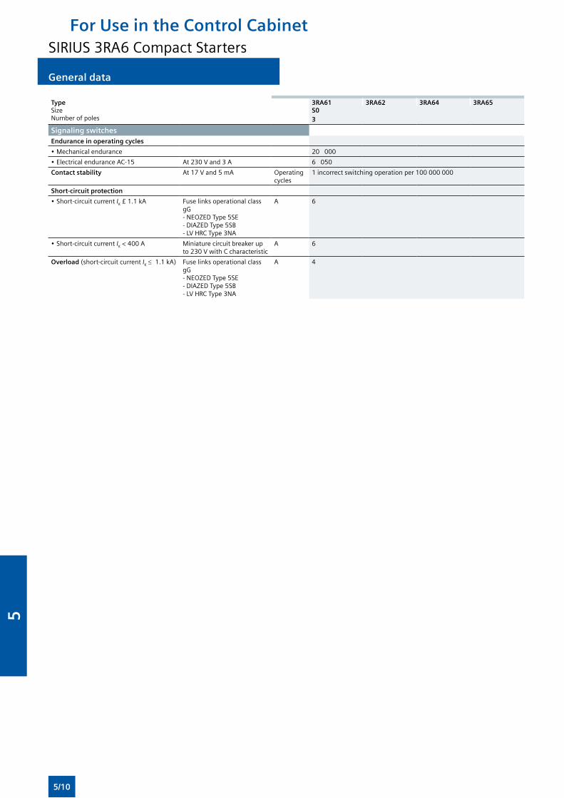
General data
Type 3RA61 3RA62 3RA64 3RA65Size S0Numberofpoles 3
Signaling switchesEndurance in operating cycles
•Mechanicalendurance 20 000
•ElectricalenduranceAC-15 At230Vand3A 6 050
Contact stability At17Vand5mA Operating cycles
1incorrectswitchingoperationper100000000
Short-circuit protection
•Short-circuitcurrentIK £ 1.1 kA Fuse links operational class gG-NEOZEDType5SE-DIAZEDType5SB -LVHRCType3NA
A 6
•Short-circuitcurrentIK < 400 A Miniaturecircuitbreakerupto230VwithCcharacteristic
A 6
Overload (short-circuit current IK ≤ 1.1kA) Fuse links operational class gG-NEOZEDType5SE-DIAZEDType5SB-LVHRCType3NA
A 4
For Use in the Control CabinetSIRIUS 3RA6 Compact Starters
5/10
5
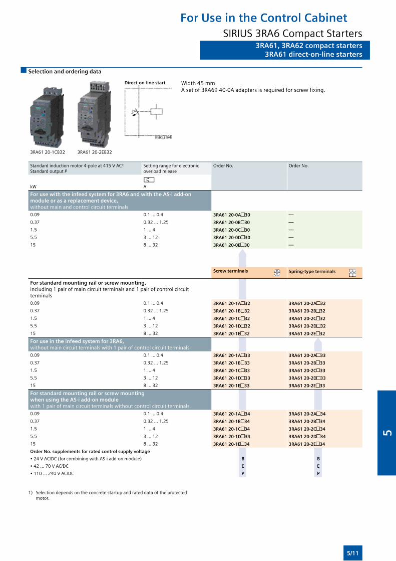
3RA61, 3RA62 compact starters3RA61 direct-on-line starters
Selection and ordering data
3RA61 20-1CB32 3RA61 20-2EB32
Direct-on-line start Width45mmAsetof3RA6940-0Aadaptersisrequiredforscrewfixing.
Standardinductionmotor4-poleat415VAC1)
Standard output PSetting range for electronic overload release
OrderNo. OrderNo.
kW A
For use with the infeed system for 3RA6 and with the AS-i add-on module or as a replacement device, withoutmainandcontrolcircuitterminals
0.09 0.1 ... 0.4 3RA61 20-0A 30 —
0.37 0.32 ... 1.25 3RA61 20-0B 30 —
1.5 1 ... 4 3RA61 20-0C 30 —
5.5 3 ... 12 3RA61 20-0D 30 —
15 8 ... 32 3RA61 20-0E 30 —
Screw terminals Spring-type terminals
For standard mounting rail or screw mounting,including 1 pair of main circuit terminals and 1 pair of control circuit terminals
0.09 0.1 ... 0.4 3RA61 20-1A 32 3RA61 20-2A 32
0.37 0.32 ... 1.25 3RA61 20-1B 32 3RA61 20-2B 32
1.5 1 ... 4 3RA61 20-1C 32 3RA61 20-2C 32
5.5 3 ... 12 3RA61 20-1D 32 3RA61 20-2D 32
15 8 ... 32 3RA61 20-1E 32 3RA61 20-2E 32
For use in the infeed system for 3RA6,withoutmaincircuitterminalswith1pairofcontrolcircuitterminals
0.09 0.1 ... 0.4 3RA61 20-1A 33 3RA61 20-2A 33
0.37 0.32 ... 1.25 3RA61 20-1B 33 3RA61 20-2B 33
1.5 1 ... 4 3RA61 20-1C 33 3RA61 20-2C 33
5.5 3 ... 12 3RA61 20-1D 33 3RA61 20-2D 33
15 8 ... 32 3RA61 20-1E 33 3RA61 20-2E 33
For standard mounting rail or screw mounting when using the AS-i add-on modulewith1pairofmaincircuitterminalswithoutcontrolcircuitterminals
0.09 0.1 ... 0.4 3RA61 20-1A 34 3RA61 20-2A 34
0.37 0.32 ... 1.25 3RA61 20-1B 34 3RA61 20-2B 34
1.5 1 ... 4 3RA61 20-1C 34 3RA61 20-2C 34
5.5 3 ... 12 3RA61 20-1D 34 3RA61 20-2D 34
15 8 ... 32 3RA61 20-1E 34 3RA61 20-2E 34
Order No. supplements for rated control supply voltage
•24VAC/DC(forcombiningwithAS-iadd-onmodule) B B
•42...70VAC/DC E E
•110...240VAC/DC P P
1) Selectiondependsontheconcretestartupandrateddataoftheprotectedmotor.
For Use in the Control CabinetSIRIUS 3RA6 Compact Starters
5/11
5
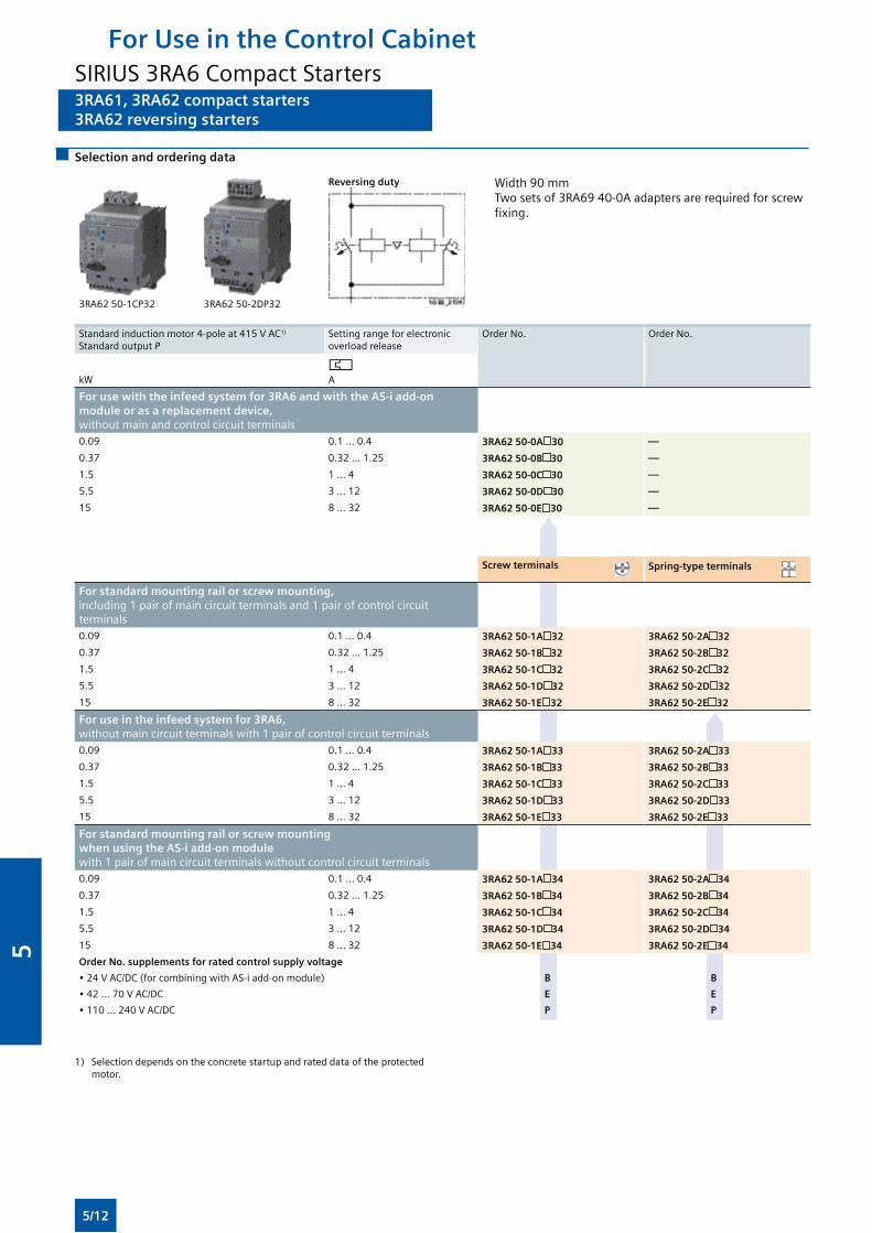
3RA61, 3RA62 compact starters3RA62 reversing starters
Selection and ordering data
3RA62 50-1CP32 3RA62 50-2DP32
Reversing duty Width90mmTwosetsof3RA6940-0Aadaptersarerequiredforscrewfixing.
Standardinductionmotor4-poleat415VAC1)
Standard output PSetting range for electronic overload release
OrderNo. OrderNo.
kW A
For use with the infeed system for 3RA6 and with the AS-i add-on module or as a replacement device, withoutmainandcontrolcircuitterminals0.09 0.1 ... 0.4 3RA62 50-0A 30 —
0.37 0.32 ... 1.25 3RA62 50-0B 30 —
1.5 1 ... 4 3RA62 50-0C 30 —
5.5 3 ... 12 3RA62 50-0D 30 —
15 8 ... 32 3RA62 50-0E 30 —
Screw terminals Spring-type terminals
For standard mounting rail or screw mounting, including 1 pair of main circuit terminals and 1 pair of control circuit terminals0.09 0.1 ... 0.4 3RA62 50-1A 32 3RA62 50-2A 32
0.37 0.32 ... 1.25 3RA62 50-1B 32 3RA62 50-2B 32
1.5 1 ... 4 3RA62 50-1C 32 3RA62 50-2C 32
5.5 3 ... 12 3RA62 50-1D 32 3RA62 50-2D 32
15 8 ... 32 3RA62 50-1E 32 3RA62 50-2E 32
For use in the infeed system for 3RA6, withoutmaincircuitterminalswith1pairofcontrolcircuitterminals0.09 0.1 ... 0.4 3RA62 50-1A 33 3RA62 50-2A 33
0.37 0.32 ... 1.25 3RA62 50-1B 33 3RA62 50-2B 33
1.5 1 ... 4 3RA62 50-1C 33 3RA62 50-2C 33
5.5 3 ... 12 3RA62 50-1D 33 3RA62 50-2D 33
15 8 ... 32 3RA62 50-1E 33 3RA62 50-2E 33
For standard mounting rail or screw mounting when using the AS-i add-on module with1pairofmaincircuitterminalswithoutcontrolcircuitterminals0.09 0.1 ... 0.4 3RA62 50-1A 34 3RA62 50-2A 34
0.37 0.32 ... 1.25 3RA62 50-1B 34 3RA62 50-2B 34
1.5 1 ... 4 3RA62 50-1C 34 3RA62 50-2C 34
5.5 3 ... 12 3RA62 50-1D 34 3RA62 50-2D 34
15 8 ... 32 3RA62 50-1E 34 3RA62 50-2E 34
Order No. supplements for rated control supply voltage
•24VAC/DC(forcombiningwithAS-iadd-onmodule) B B
•42...70VAC/DC E E
•110...240VAC/DC P P
1) Selectiondependsontheconcretestartupandrateddataoftheprotectedmotor.
For Use in the Control CabinetSIRIUS 3RA6 Compact Starters
5/12
5
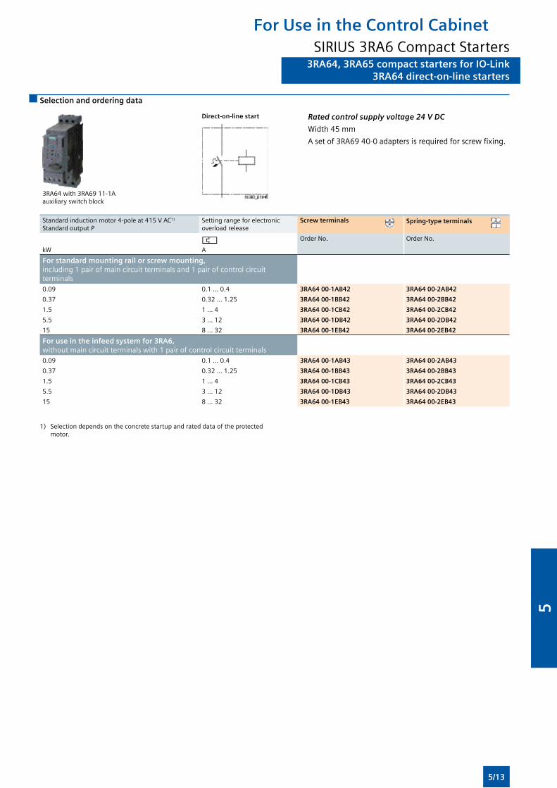
3RA64, 3RA65 compact starters for IO-Link3RA64 direct-on-line starters
Selection and ordering data
3RA64 with3RA6911-1A auxiliaryswitchblock
Direct-on-line start Rated control supply voltage 24 V DC
Width45mm
Asetof3RA6940-0adaptersisrequiredforscrewfixing.
Standardinductionmotor4-poleat415VAC1)
Standard output PSetting range for electronic overload release
Screw terminals Spring-type terminals
kW A
OrderNo. OrderNo.
For standard mounting rail or screw mounting, including 1 pair of main circuit terminals and 1 pair of control circuit terminals0.09 0.1 ... 0.4 3RA64 00-1AB42 3RA64 00-2AB42
0.37 0.32 ... 1.25 3RA64 00-1BB42 3RA64 00-2BB42
1.5 1 ... 4 3RA64 00-1CB42 3RA64 00-2CB42
5.5 3 ... 12 3RA64 00-1DB42 3RA64 00-2DB42
15 8 ... 32 3RA64 00-1EB42 3RA64 00-2EB42
For use in the infeed system for 3RA6, withoutmaincircuitterminalswith1pairofcontrolcircuitterminals0.09 0.1 ... 0.4 3RA64 00-1AB43 3RA64 00-2AB43
0.37 0.32 ... 1.25 3RA64 00-1BB43 3RA64 00-2BB43
1.5 1 ... 4 3RA64 00-1CB43 3RA64 00-2CB43
5.5 3 ... 12 3RA64 00-1DB43 3RA64 00-2DB43
15 8 ... 32 3RA64 00-1EB43 3RA64 00-2EB43
1) Selectiondependsontheconcretestartupandrateddataoftheprotectedmotor.
For Use in the Control CabinetSIRIUS 3RA6 Compact Starters
5/13
5
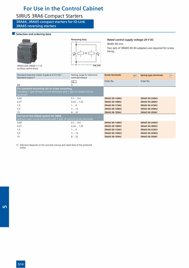
3RA64, 3RA65 compact starters for IO-Link3RA65 reversing starters
Selection and ordering data
3RA65.with3RA6911-1A auxiliaryswitchblock
Reversing duty Rated control supply voltage 24 V DC
Width90mm
Twosetsof3RA6940-0Aadaptersarerequiredforscrewfixing.
Standardinductionmotor4-poleat415VAC1)
Standard output PSetting range for electronic overload release
Screw terminals Spring-type terminals
kW A
OrderNo. OrderNo.
For standard mounting rail or screw mounting, including 1 pair of main circuit terminals and 1 pair of control circuit terminals0.09 0.1 ... 0.4 3RA65 00-1AB42 3RA65 00-2AB42
0.37 0.32 ... 1.25 3RA65 00-1BB42 3RA65 00-2BB42
1.5 1 ... 4 3RA65 00-1CB42 3RA65 00-2CB42
5.5 3 ... 12 3RA65 00-1DB42 3RA65 00-2DB42
15 8 ... 32 3RA65 00-1EB42 3RA65 00-2EB42
For use in the infeed system for 3RA6, withoutmaincircuitterminalswith1pairofcontrolcircuitterminals0.09 0.1 ... 0.4 3RA65 00-1AB43 3RA65 00-2AB43
0.37 0.32 ... 1.25 3RA65 00-1BB43 3RA65 00-2BB43
1.5 1 ... 4 3RA65 00-1CB43 3RA65 00-2CB43
5.5 3 ... 12 3RA65 00-1DB43 3RA65 00-2DB43
15 8 ... 32 3RA65 00-1EB43 3RA65 00-2EB43
1) Selectiondependsontheconcretestartupandrateddataoftheprotectedmotor.
For Use in the Control CabinetSIRIUS 3RA6 Compact Starters
5/14
5
Accessories
Overview
Accessories for SIRIUS 3RA6 compact starters
Thefollowingaccessoriesareavailablespeciallyforthe3RA6compact starters:
• AS-i add-on module: seeAS-InterfaceAdd-OnModulesfor3RA6, page 5/20
• Externalauxiliaryswitchblocks:Snap-onauxiliaryswitchasversions2NO,2NCand1NO+1NCwithscreworspring-typeconnections;thecontactsoftheauxiliaryswitchblockopenandclosejointlywiththemaincontactsofthecompactstarter.TheNCcontactsaredesignedasmirrorcontacts.
• Control kit: aid for manually closing the main contacts in order tocheckthewiringandmotordirectionunderconditionsofshort-circuit protection
• Adapterforscrewfixingthecompactstarter,includingpush-inlugs
• Maincircuitterminals:Availablewithscrewandspring-typeterminals
• Maincircuitterminalsmixedconnectionmethod: Withthemaincircuitterminalsmixedconnectionmethoditisalsopossibleinthemaincircuittoswitchfromscrewterminals on the line side to spring-type terminals on the outgoingside.Thisenablesforexampletheside-by-sidemountingofseveralcompactstartersandtheircost-efficientconnection using 3-phase busbars on the infeed side. The motors are then connected directly by the quick and reliably contacting spring-type connection method.
Accessories for infeed using three-phase busbar systems
The three-phase busbars can be used as an easy, time-saving and clearly arranged means of feeding SIRIUS 3RA6 compact starters withscrewconnection.MotorprotectioncircuitbreakersizesS00and S0 can also be integrated.
Thebusbarsaresuitableforbetween2and5devices.However,anykindofextensionuptoamaximumsummationcurrentof63 A is possible by clamping the tags of an additional busbar (rotatedby180°)underneaththeterminalsoftherespectivelastmotor protection circuit breaker.
Aconnectingpieceisrequiredforthecombinationwith3RV1motorprotectioncircuitbreakersizeS00.MotorprotectioncircuitbreakersS00andS0ofthe3RV2seriescanbecombinedinanyway(withoutaspecialconnectingpiece).Themotorprotectioncircuit breakers are supplied by appropriate feeder terminals.
Thethree-phasebusbarsystemsarefinger-safebutemptyconnectiontagsmustbefittedwithcovers.Theyaredesignedforanyshort-circuitstresswhichcanoccurattheoutputsideof connected SIRIUS 3RA6 compact starters or motor protection circuit breakers.
Busbar adapters for 60 mm systems
Thecompactstartersaremounteddirectlywiththeaidofbusbaradaptersonbusbarsystemswith60mmcenter-to-centerclearance in order to save space and to reduce infeed times and costs.Thesestartersaresuitableforcopperbusbarswithawidthfrom 12 to 30 mm. The busbars can be 4 to 5 mm or 10 mm thick.
The8USbusbarsystemcanbeloadedwithamaximumsummation current of 630 A.
The “reversing starter” version requires a device holder along side the busbar adapter for lateral mounting.
The compact starters are snapped onto the adapter and connected on the line side. This prepared unit is then plugged directly onto the busbar system, and is thus connected both mechanically and electrically at the same time.
Accessories for operation with closed control cabinet doors
Door-coupling rotary operating mechanisms for standard and emergency-stop applications are available for operating the compactstarterwithclosedcontrolcabinetdoors.
Accessories for SIRIUS 3RA6 compact starters in IO-Link version
Thefollowingaccessoriesareavailablespeciallyforthe3RA64,3RA65 compact starters:
• The4SISIRIUSelectronicmoduleasIO-LinkmasterallowsforthesimpleandeconomicalconnectionofSIRIUScontrolswithIO-Link(e.g.uptofourgroupsof4compactstarters)tothemultifunctionalSIMATICET200SdistributedI/Osystem.
• Additional connection cables for side-by-side mounting of up to 4 compact starters
• Operator panel for on-site control and diagnostics of up to 4 compact starters coupled to each other
For Use in the Control CabinetSIRIUS 3RA6 Compact Starters
5/15
5
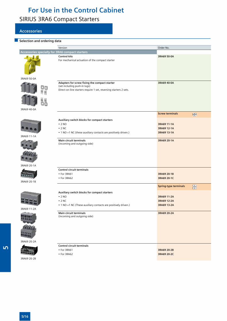
Accessories
Selection and ordering data
Version OrderNo.
Accessories specially for 3RA6 compact starters
3RA6950-0A
Control kitsFor mechanical actuation of the compact starter
3RA69 50-0A
3RA6940-0A
Adapters for screw fixing the compact starter (setincludingpush-inlugs)Direct-on-line starters require 1 set, reversing starters 2 sets.
3RA69 40-0A
Screw terminals
3RA6911-1A
Auxiliary switch blocks for compact starters
•2NO 3RA69 11-1A
•2NC 3RA69 12-1A
•1NO+1NC(theseauxiliarycontactsarepositivelydriven.) 3RA69 13-1A
3RA6920-1A
Main circuit terminals (incomingandoutgoingside)
3RA69 20-1A
3RA6920-1B
Control circuit terminals
•For3RA61 3RA69 20-1B
•For3RA62 3RA69 20-1C
Spring-type terminals
3RA6911-2A
Auxiliary switch blocks for compact starters
•2NO 3RA69 11-2A
•2NC 3RA69 12-2A
•1NO+1NC(Theseauxiliarycontactsarepositivelydriven.) 3RA69 13-2A
3RA6920-2A
Main circuit terminals (incomingandoutgoingside)
3RA69 20-2A
3RA6920-2B
Control circuit terminals
•For3RA61 3RA69 20-2B
•For3RA62 3RA69 20-2C
For Use in the Control CabinetSIRIUS 3RA6 Compact Starters
5/16
5
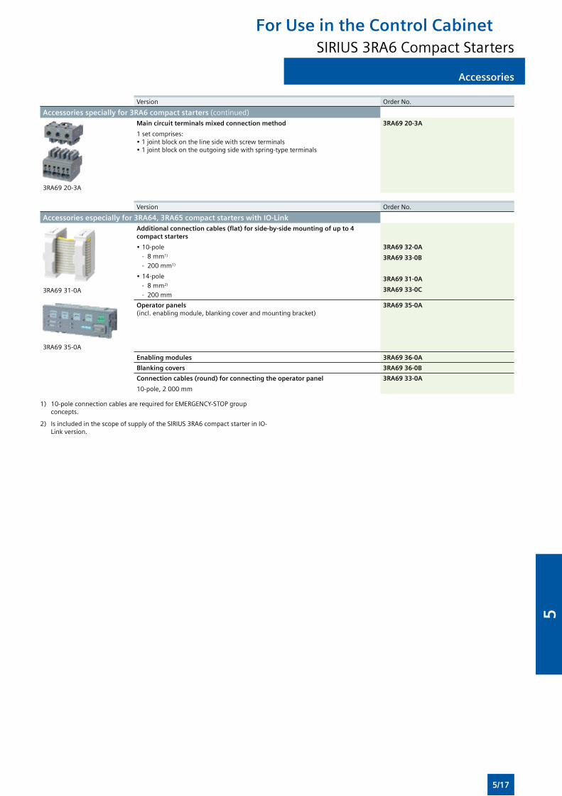
Accessories
Version OrderNo.
Accessories specially for 3RA6 compact starters (continued)
3RA6920-3A
Main circuit terminals mixed connection method
1 set comprises:•1jointblockonthelinesidewithscrewterminals•1jointblockontheoutgoingsidewithspring-typeterminals
3RA69 20-3A
Version OrderNo.
Accessories especially for 3RA64, 3RA65 compact starters with IO-Link
3RA6931-0A
Additional connection cables (flat) for side-by-side mounting of up to 4 compact starters
•10-pole - 8 mm1)
- 200 mm1)
•14-pole - 8 mm2)
- 200 mm
3RA69 32-0A
3RA69 33-0B
3RA69 31-0A
3RA69 33-0C
3RA6935-0A
Operator panels (incl.enablingmodule,blankingcoverandmountingbracket)
3RA69 35-0A
Enabling modules 3RA69 36-0A
Blanking covers 3RA69 36-0B
Connection cables (round) for connecting the operator panel
10-pole, 2 000 mm
3RA69 33-0A
1) 10-poleconnectioncablesarerequiredforEMERGENCY-STOPgroupconcepts.
2) IsincludedinthescopeofsupplyoftheSIRIUS3RA6compactstarterinIO-Link version.
For Use in the Control CabinetSIRIUS 3RA6 Compact Starters
5/17
5
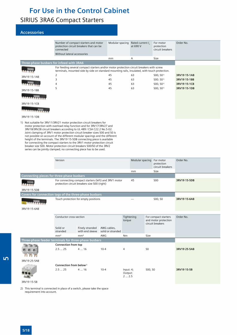
Accessories
Numberofcompactstartersandmotorprotection circuit breakers that can be connected
Withoutlateralaccessories
Modularspacing Rated current In at690V
For motor protection circuit breakers
OrderNo.
mm A Size
Three-phase busbars for infeed with 3RA6
3RV1915-1AB
3RV1915-1BB
3RV1915-1CB
3RV1915-1DB
Forfeedingseveralcompactstartersand/ormotorprotectioncircuitbreakerswithscrewterminals,mountedsidebysideonstandardmountingrails,insulated,withtouchprotection.
2 45 63 S00, S01) 3RV19 15-1AB
3 45 63 S00. S01) 3RV19 15-1BB
4 45 63 S00, S01) 3RV19 15-1CB
5 45 63 S00, S01) 3RV19 15-1DB
1) Notsuitablefor3RV11/3RV21motorprotectioncircuitbreakersformotorprotectionwithoverloadrelayfunctionandfor3RV17/3RV27and3RV18/3RV28circuitbreakersaccordingtoUL489/CSAC22.2No.5-02. Jointclampingof3RV1motorprotectioncircuitbreakersizesS00andS0isnot possible on account of the different modular spacings and the different heightoftheterminals.The3RV1915-5DBconnectingpieceisavailableforconnectingthecompactstarterstothe3RV1motorprotectioncircuitbreakersizeS00.MotorprotectioncircuitbreakersS00/S0ofthe3RV2series can be jointly clamped; no connecting piece has to be used.
Version Modularspacing For motor protection circuit breakers
OrderNo.
mm Size
Connecting pieces for three-phase busbars
3RV1915-5DB
Forconnectingcompactstarters(left)and3RV1motorprotectioncircuitbreakerssizeS00(right)
45 S00 3RV19 15-5DB
Covers for connection tags of the three-phase busbars
3RV1915-6AB
Touch protection for empty positions — S00, S0 3RV19 15-6AB
Conductor cross-section Tightening torque
For compact starters and motor protection circuit breakers
OrderNo.
Solid or stranded
Finely stranded withendsleeve
AWGcables,solid or stranded
mm² mm² AWG Nm Size
Three-phase feeder terminals for three-phase busbars
3RV1925-5AB
Connection from top
2.5 ... 25 4 ... 16 10-4 4 S0 3RV19 25-5AB
3RV1915-5B
Connection from below2)
2.5 ... 25 4 ... 16 10-4 Input: 4; Output: 2 ... 2.5
S00, S0 3RV19 15-5B
2) Thisterminalisconnectedinplaceofaswitch,pleasetakethespacerequirement into account.
For Use in the Control CabinetSIRIUS 3RA6 Compact Starters
5/18
5
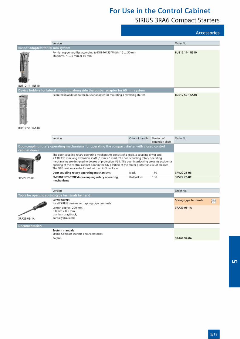
Accessories
Version OrderNo.
Busbar adapters for 60 mm system
8US1211-1NS10
ForflatcopperprofilesaccordingtoDIN46433Width:12...30mmThickness: 4 ... 5 mm or 10 mm
8US12 11-1NS10
Device holders for lateral mounting along side the busbar adapter for 60 mm system
8US12 50-1AA10
Required in addition to the busbar adapter for mounting a reversing starter 8US12 50-1AA10
Version Color of handle Versionofextensionshaft
OrderNo.
Door-coupling rotary operating mechanisms for operating the compact starter with closed control cabinet doors
3RV2926-0B
The door-coupling rotary operating mechanisms consist of a knob, a coupling driver and a130/330mmlongextensionshaft(6mmx6mm).Thedoor-couplingrotaryoperatingmechanisms are designed to degree of protection IP65. The door interlocking prevents accidental openingofthecontrolcabinetdoorintheONpositionofthemotorprotectioncircuitbreaker.TheOFFpositioncanbelockedwithupto3padlocks.
Door-coupling rotary operating mechanisms Black 130 3RV29 26-0B
EMERGENCY-STOP door-coupling rotary operating mechanisms
Red/yellow 130 3RV29 26-0C
Version OrderNo.
Tools for opening spring-type terminals by hand
3RA2908-1A
ScrewdriversforallSIRIUSdeviceswithspring-typeterminals
Spring-type terminals
Lengthapprox.200mm,3.0mmx0.5mm,titanium gray/black, partially insulated
3RA29 08-1A
DocumentationSystem manualsSIRIUS Compact Starters and Accessories
English 3RA69 92-0A
For Use in the Control CabinetSIRIUS 3RA6 Compact Starters
5/19
5
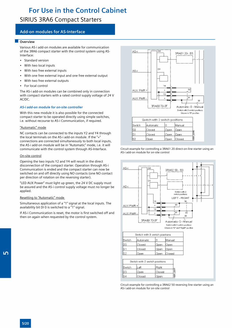
Add-on modules for AS-Interface
Overview
VariousAS-iadd-onmodulesareavailableforcommunicationofthe3RA6compactstarterwiththecontrolsystemusingAS-Interface:
• Standard version
• Withtwolocalinputs
• Withtwofreeexternalinputs
• Withonefreeexternalinputandonefreeexternaloutput
• Withtwofreeexternaloutputs
• For local control
The AS-i add-on modules can be combined only in connection withcompactstarterswitharatedcontrolsupplyvoltageof24VAC/DC.
AS-i add-on module for on-site controller
Withthisnewmoduleitisalsopossiblefortheconnectedcompactstartertobeoperateddirectlyusingsimpleswitches,i.e.withoutrecoursetoAS-iCommunication,ifrequired.
“Automatic” mode
NCcontactscanbeconnectedtotheinputsY2andY4throughthe local terminals on the AS-i add-on module. If the “+” connections are connected simultaneously to both local inputs, theAS-iadd-onmodulewillbein“Automatic”mode,i.e.itwillcommunicatewiththecontrolsystemthroughAS-Interface.
On-site control
OpeningthetwoinputsY2andY4willresultinthedirectdisconnection of the compact starter. Operation through AS-i CommunicationisendedandthecompactstartercannowbeswitchedonandoffdirectlyusingNOcontacts(oneNOcontactperdirectionofrotationonthereversingstarter).
“LEDAUXPower”mustlightupgreen,the24VDCsupplymustbe assured and the AS-i control supply voltage must no longer be applied.
Resetting to “Automatic” mode
Simultaneous application of a “1” signal at the local inputs. The availabilitybitDI0isswitchedtoa“1”signal.
IfAS-iCommunicationisreset,themotorisfirstswitchedoffandthenonagainwhenrequestedbythecontrolsystem.
Circuitexampleforcontrollinga3RA6120direct-on-linestarterusinganAS-i add-on module for on-site control
Circuitexampleforcontrollinga3RA6250reversinglinestarterusinganAS-i add-on module for on-site control
For Use in the Control CabinetSIRIUS 3RA6 Compact Starters
5/20
5
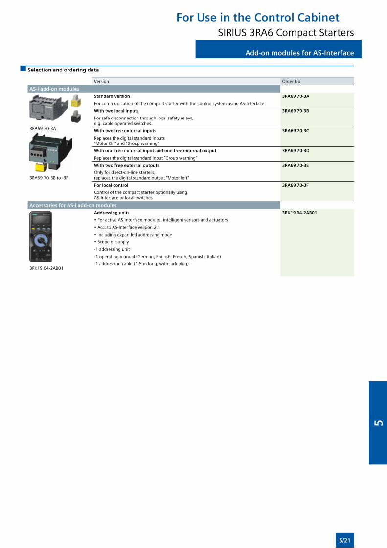
Add-on modules for AS-Interface
Selection and ordering data
Version OrderNo.
AS-i add-on modules
3RA6970-3A
3RA6970-3Bto-3F
Standard version
ForcommunicationofthecompactstarterwiththecontrolsystemusingAS-Interface
3RA69 70-3A
With two local inputs
For safe disconnection through local safety relays, e.g.cable-operatedswitches
3RA69 70-3B
With two free external inputs
Replaces the digital standard inputs “MotorOn”and“Groupwarning”
3RA69 70-3C
With one free external input and one free external output
Replacesthedigitalstandardinput“Groupwarning”
3RA69 70-3D
With two free external outputs
Only for direct-on-line starters, replacesthedigitalstandardoutput“Motorleft”
3RA69 70-3E
For local control
Control of the compact starter optionally using AS-Interfaceorlocalswitches
3RA69 70-3F
Accessories for AS-i add-on modules
3RK1904-2AB01
Addressing units
•ForactiveAS-Interfacemodules,intelligentsensorsandactuators
•Acc.toAS-InterfaceVersion2.1
•Includingexpandedaddressingmode
•Scopeofsupply
-1 addressing unit
-1operatingmanual(German,English,French,Spanish,Italian)
-1addressingcable(1.5mlong,withjackplug)
3RK19 04-2AB01
For Use in the Control CabinetSIRIUS 3RA6 Compact Starters
5/21
5
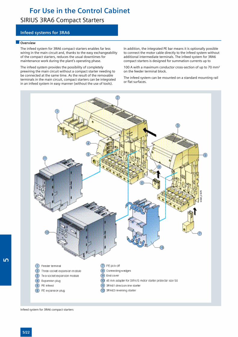
Infeed systems for 3RA6
Overview
The infeed system for 3RA6 compact starters enables far less wiringinthemaincircuitand,thankstotheeasyexchangeabilityofthecompactstarters,reducestheusualdowntimesformaintenanceworkduringtheplant’soperatingphase.
The infeed system provides the possibility of completely prewiringthemaincircuitwithoutacompactstarterneedingtobe connected at the same time. As the result of the removable terminals in the main circuit, compact starters can be integrated inaninfeedsystemineasymanner(withouttheuseoftools).
In addition, the integrated PE bar means it is optionally possible toconnectthemotorcabledirectlytotheinfeedsystemwithoutadditional intermediate terminals. The infeed system for 3RA6 compact starters is designed for summation currents up to
100Awithamaximumconductorcross-sectionofupto70mm²on the feeder terminal block.
The infeed system can be mounted on a standard mounting rail orflatsurfaces.
Infeed system for 3RA6 compact starters
For Use in the Control CabinetSIRIUS 3RA6 Compact Starters
5/22
5
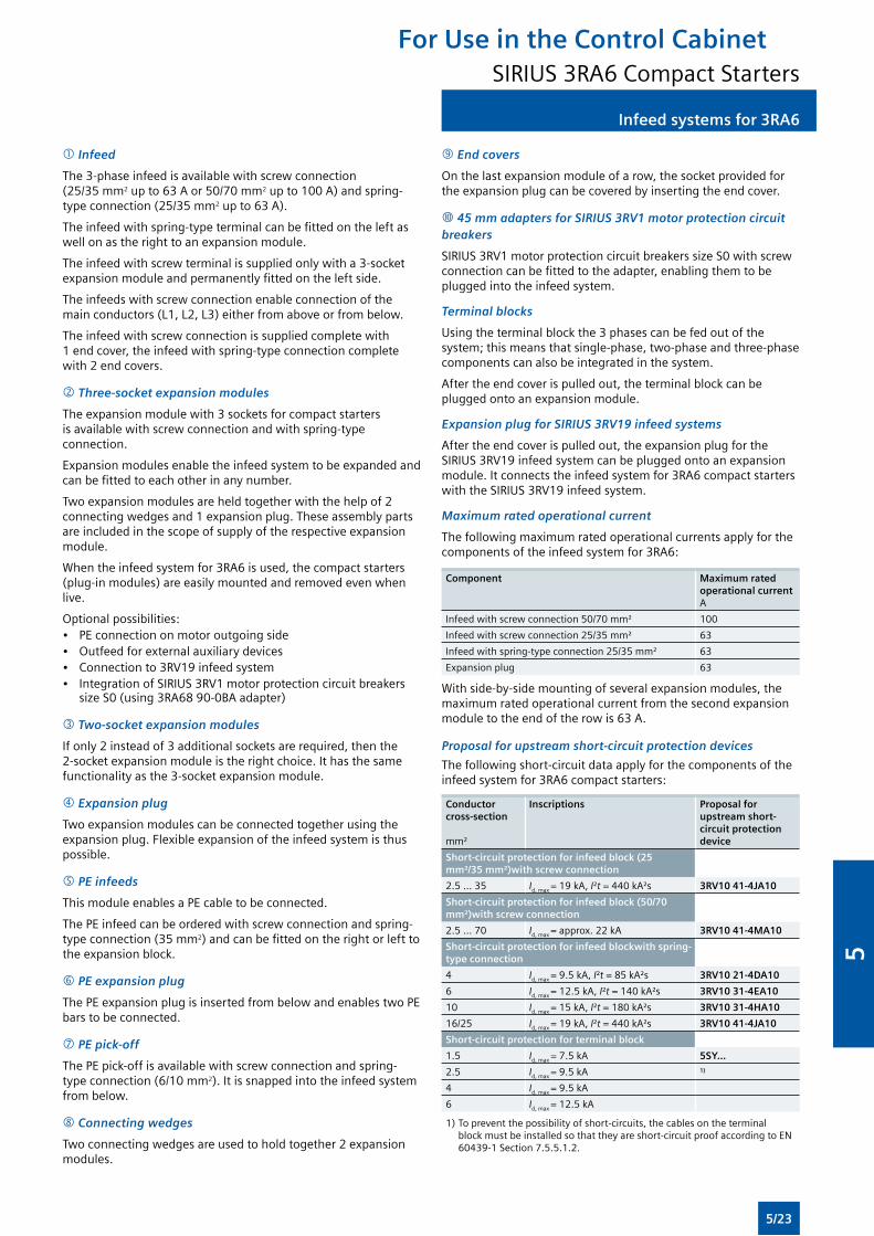
Infeed systems for 3RA6
Infeed
The3-phaseinfeedisavailablewithscrewconnection(25/35 mm2upto63Aor50/70mm2upto100A)andspring-type connection (25/35 mm2upto63A).
Theinfeedwithspring-typeterminalcanbefittedontheleftaswellonastherighttoanexpansionmodule.
Theinfeedwithscrewterminalissuppliedonlywitha3-socketexpansionmoduleandpermanentlyfittedontheleftside.
Theinfeedswithscrewconnectionenableconnectionofthemainconductors(L1,L2,L3)eitherfromaboveorfrombelow.
Theinfeedwithscrewconnectionissuppliedcompletewith1endcover,theinfeedwithspring-typeconnectioncompletewith2endcovers.
Three-socket expansion modules
Theexpansionmodulewith3socketsforcompactstartersisavailablewithscrewconnectionandwithspring-typeconnection.
Expansionmodulesenabletheinfeedsystemtobeexpandedandcanbefittedtoeachotherinanynumber.
Twoexpansionmodulesareheldtogetherwiththehelpof2connectingwedgesand1expansionplug.Theseassemblypartsareincludedinthescopeofsupplyoftherespectiveexpansionmodule.
Whentheinfeedsystemfor3RA6isused,thecompactstarters(plug-inmodules)areeasilymountedandremovedevenwhenlive.
Optional possibilities:• PE connection on motor outgoing side• Outfeedforexternalauxiliarydevices• Connectionto3RV19infeedsystem• IntegrationofSIRIUS3RV1motorprotectioncircuitbreakers
sizeS0(using3RA6890-0BAadapter)
Two-socket expansion modules
If only 2 instead of 3 additional sockets are required, then the 2-socketexpansionmoduleistherightchoice.Ithasthesamefunctionalityasthe3-socketexpansionmodule.
Expansion plug
Twoexpansionmodulescanbeconnectedtogetherusingtheexpansionplug.Flexibleexpansionoftheinfeedsystemisthuspossible.
PE infeeds
This module enables a PE cable to be connected.
ThePEinfeedcanbeorderedwithscrewconnectionandspring-type connection (35 mm2)andcanbefittedontherightorlefttotheexpansionblock.
PE expansion plug
ThePEexpansionplugisinsertedfrombelowandenablestwoPEbars to be connected.
PE pick-off
ThePEpick-offisavailablewithscrewconnectionandspring-type connection (6/10 mm2).Itissnappedintotheinfeedsystemfrombelow.
Connecting wedges
Twoconnectingwedgesareusedtoholdtogether2expansionmodules.
End covers
Onthelastexpansionmoduleofarow,thesocketprovidedfortheexpansionplugcanbecoveredbyinsertingtheendcover.
45 mm adapters for SIRIUS 3RV1 motor protection circuit breakers
SIRIUS3RV1motorprotectioncircuitbreakerssizeS0withscrewconnectioncanbefittedtotheadapter,enablingthemtobeplugged into the infeed system.
Terminal blocks
Using the terminal block the 3 phases can be fed out of the system;thismeansthatsingle-phase,two-phaseandthree-phasecomponents can also be integrated in the system.
After the end cover is pulled out, the terminal block can be pluggedontoanexpansionmodule.
Expansion plug for SIRIUS 3RV19 infeed systems
Aftertheendcoverispulledout,theexpansionplugfortheSIRIUS3RV19infeedsystemcanbepluggedontoanexpansionmodule. It connects the infeed system for 3RA6 compact starters withtheSIRIUS3RV19infeedsystem.
Maximum rated operational current
Thefollowingmaximumratedoperationalcurrentsapplyforthecomponents of the infeed system for 3RA6:
Component Maximum rated operational current A
Infeedwithscrewconnection50/70mm² 100
Infeedwithscrewconnection25/35mm² 63
Infeedwithspring-typeconnection25/35mm² 63
Expansionplug 63
Withside-by-sidemountingofseveralexpansionmodules,themaximumratedoperationalcurrentfromthesecondexpansionmoduletotheendoftherowis63A.
Proposal for upstream short-circuit protection devices
Thefollowingshort-circuitdataapplyforthecomponentsoftheinfeed system for 3RA6 compact starters:
Conductor cross-section
mm²
Inscriptions Proposal for upstream short-circuit protection device
Short-circuit protection for infeed block (25 mm²/35 mm²)with screw connection
2.5 ... 35 Id,max=19kA,I²t=440kA²s 3RV10 41-4JA10
Short-circuit protection for infeed block (50/70 mm²)with screw connection
2.5...70 Id,max=approx.22kA 3RV10 41-4MA10
Short-circuit protection for infeed blockwith spring-type connection
4 Id,max=9.5kA,I²t=85kA²s 3RV10 21-4DA10
6 Id,max= 12.5 kA, I²t=140kA²s 3RV10 31-4EA10
10 Id,max= 15 kA, I²t=180kA²s 3RV10 31-4HA10
16/25 Id,max=19kA,I²t=440kA²s 3RV10 41-4JA10
Short-circuit protection for terminal block
1.5 Id,max=7.5kA 5SY...
2.5 Id,max=9.5kA1)
4 Id,max=9.5kA
6 Id,max= 12.5 kA
1)Topreventthepossibilityofshort-circuits,thecablesontheterminalblockmustbeinstalledsothattheyareshort-circuitproofaccordingtoEN60439-1Section7.5.5.1.2.
For Use in the Control CabinetSIRIUS 3RA6 Compact Starters
5/23
5
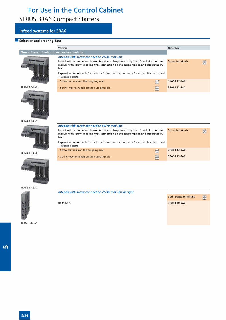
Infeed systems for 3RA6
Selection and ordering data
Version OrderNo.
Three-phase infeeds and expansion modules
3RA68 12-8AB
3RA68 12-8AC
Infeeds with screw connection 25/35 mm2 leftInfeed with screw connection at line side withapermanentlyfitted 3-socket expansion module with screw or spring-type connection on the outgoing side and integrated PE bar
Expansion module with3socketsfor3direct-on-linestartersor1direct-on-linestarterand1 reversing starter
Screw terminals
•Screwterminalsontheoutgoingside 3RA68 12-8AB
•Spring-typeterminalsontheoutgoingside 3RA68 12-8AC
3RA68 13-8AB
3RA68 13-8AC
Infeeds with screw connection 50/70 mm2 leftInfeed with screw connection at line side withapermanentlyfitted3-socket expansion module with screw or spring-type connection on the outgoing side and integrated PE bar
Expansion module with3socketsfor3direct-on-linestartersor1direct-on-linestarterand1 reversing starter
Screw terminals
•Screwterminalsontheoutgoingside 3RA68 13-8AB
•Spring-typeterminalsontheoutgoingside 3RA68 13-8AC
3RA68 30-5AC
Infeeds with screw connection 25/35 mm2 left or right
Spring-type terminals
Up to 63 A 3RA68 30-5AC
For Use in the Control CabinetSIRIUS 3RA6 Compact Starters
5/24
5
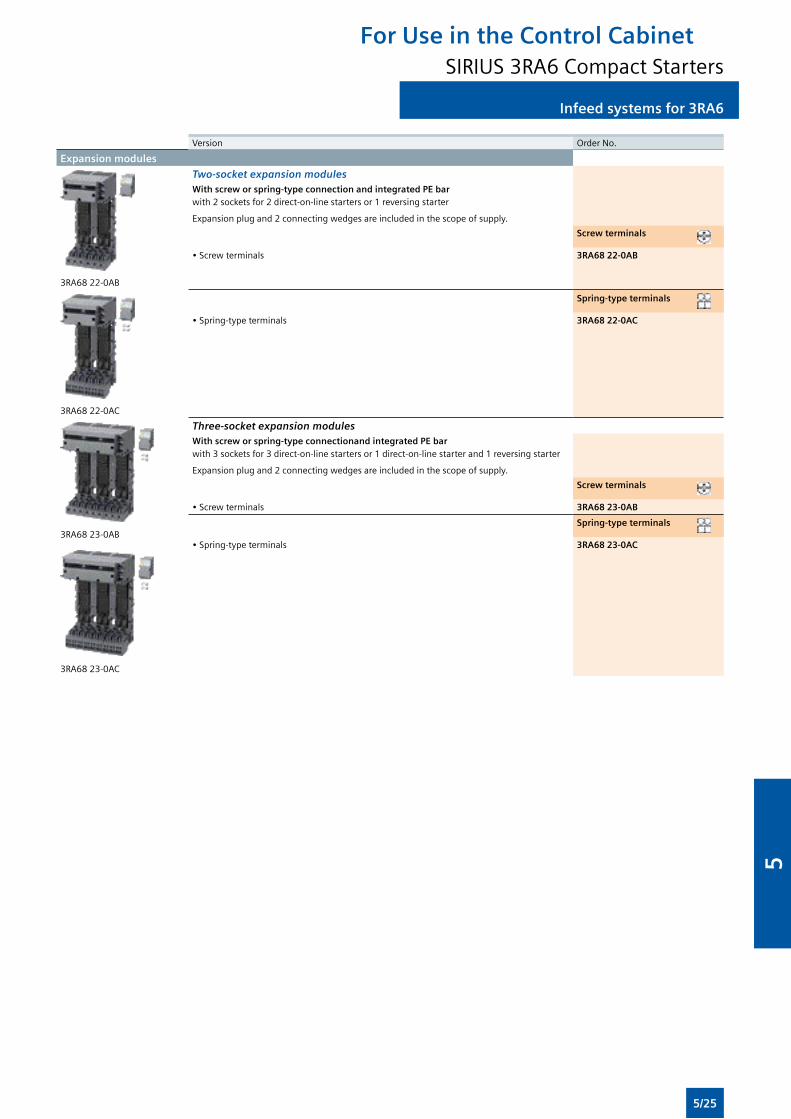
Infeed systems for 3RA6
Version OrderNo.
Expansion modules
3RA68 22-0AB
Two-socket expansion modulesWith screw or spring-type connection and integrated PE bar with2socketsfor2direct-on-linestartersor1reversingstarter
Expansionplugand2connectingwedgesareincludedinthescopeofsupply.
Screw terminals
•Screwterminals 3RA68 22-0AB
3RA68 22-0AC
Spring-type terminals
•Spring-typeterminals 3RA68 22-0AC
3RA68 23-0AB
3RA68 23-0AC
Three-socket expansion modulesWith screw or spring-type connectionand integrated PE bar with3socketsfor3direct-on-linestartersor1direct-on-linestarterand1reversingstarter
Expansionplugand2connectingwedgesareincludedinthescopeofsupply.
Screw terminals
•Screwterminals 3RA68 23-0AB
Spring-type terminals
•Spring-typeterminals 3RA68 23-0AC
For Use in the Control CabinetSIRIUS 3RA6 Compact Starters
5/25
5
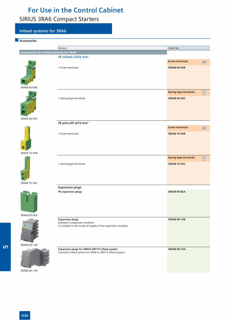
Infeed systems for 3RA6
Accessories
Version OrderNo.
Accessories for infeed systems for 3RA6
PE infeeds 25/35 mm2
3RA68 60-6AB
Screw terminals
•Screwterminals 3RA68 60-6AB
3RA68 60-5AC
Spring-type terminals
•Spring-typeterminals 3RA68 60-5AC
PE pick-offs 6/10 mm2
3RA6870-4AB
Screw terminals
•Screwterminals 3RA68 70-4AB
3RA6870-3AC
Spring-type terminals
•Spring-typeterminals 3RA68 70-3AC
Expansion plugs
3RA6890-0EA
PE expansion plugs 3RA68 90-0EA
3RA6890-1AB
Expansion plugs between2expansionmodulesIsincludedinthescopeofsupplyoftheexpansionmodules.
3RA68 90-1AB
3RA6890-1AA
Expansion plugs for SIRIUS 3RV19 infeed system Connectsinfeedsystemfor3RA6to3RV19infeedsystem
3RA68 90-1AA
For Use in the Control CabinetSIRIUS 3RA6 Compact Starters
5/26
5
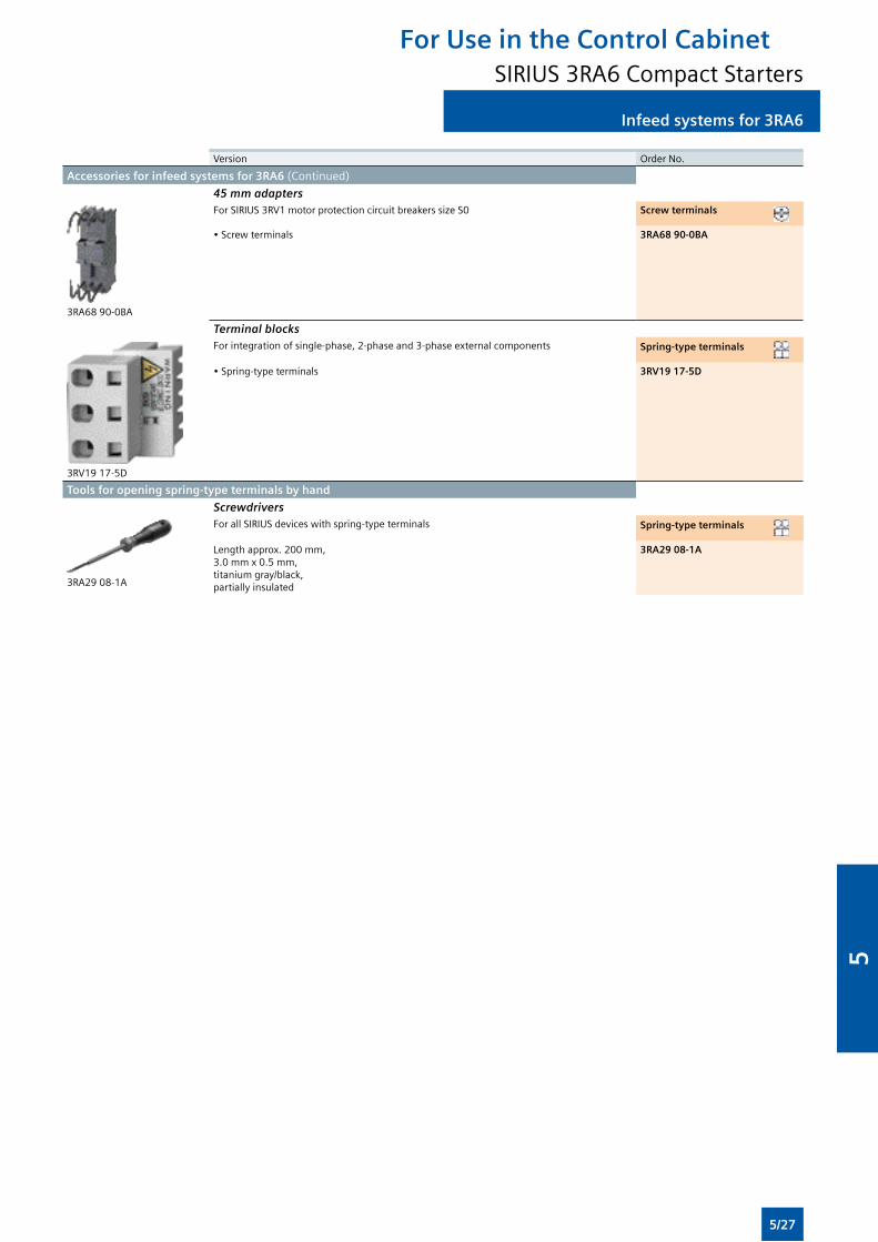
Infeed systems for 3RA6
Version OrderNo.
Accessories for infeed systems for 3RA6 (Continued)
45 mm adapters
3RA6890-0BA
ForSIRIUS3RV1motorprotectioncircuitbreakerssizeS0 Screw terminals
•Screwterminals 3RA68 90-0BA
Terminal blocks
3RV1917-5D
Forintegrationofsingle-phase,2-phaseand3-phaseexternalcomponents Spring-type terminals
•Spring-typeterminals 3RV19 17-5D
Tools for opening spring-type terminals by hand
Screwdrivers
3RA2908-1A
ForallSIRIUSdeviceswithspring-typeterminals Spring-type terminals
Lengthapprox.200mm, 3.0mmx0.5mm, titanium gray/black, partially insulated
3RA29 08-1A
For Use in the Control CabinetSIRIUS 3RA6 Compact Starters
5/27
5

Notes
For Use in the Control Cabinet
5/28
5

6Monitoring and Control Devices
Residual current monitoring
6/54 - Residual-current monitoring relays
6/56 - Summation current transformers
Insulation monitoring
6/57 - For ungrounded AC networks
6/59 - For ungrounded DC networks
Level monitoring
6/61 - Level monitoring relays
6/64 - Level monitoring sensors
6/65 Accessories
SIRIUS 3RS10, 3RS20 Temperature Monitoring Relays
6/66 General data
6/69 Relays, analogically adjustable for 1 sensor
6/72 Relays, digitally adjustable for 1 sensor
6/74 Relays, digitally adjustable for up to 3 sensors
6/76 Accessories
SIRIUS 3RN1 Thermistor Motor Protection
6/77 For PTC sensors
6/2 Introduction
SIMOCODE 3UF Motor Management and Control Devices
SIMOCODE pro 3UF7
6/4 General data
6/11 Basic units
6/12 Expansion modules
6/13 Failsafe expansion modules
6/14 Accessories
SIRIUS 3TK28 Safety Relays
6/18 General data
6/19 With relay enabling circuits
Timing Relays
6/24 General data
6/25 SIRIUS 3RP15 timing relays in industrial enclosure, 22.5 mm
6/30 Accessories
SIRIUS 3RR, 3UG Monitoring Relays for Electrical and Additional Measurements
SIRIUS 3RR2 Monitoring Relays for Mounting onto 3RT2 Contactors
6/31 General data
6/34 Current monitoring
SIRIUS 3UG Monitoring Relays for Stand-Alone Installation
6/39 General data
6/40 Line monitoring
6/45 Voltage monitoring
6/48 Current monitoring
6/51 Power factor and active current monitoring
6
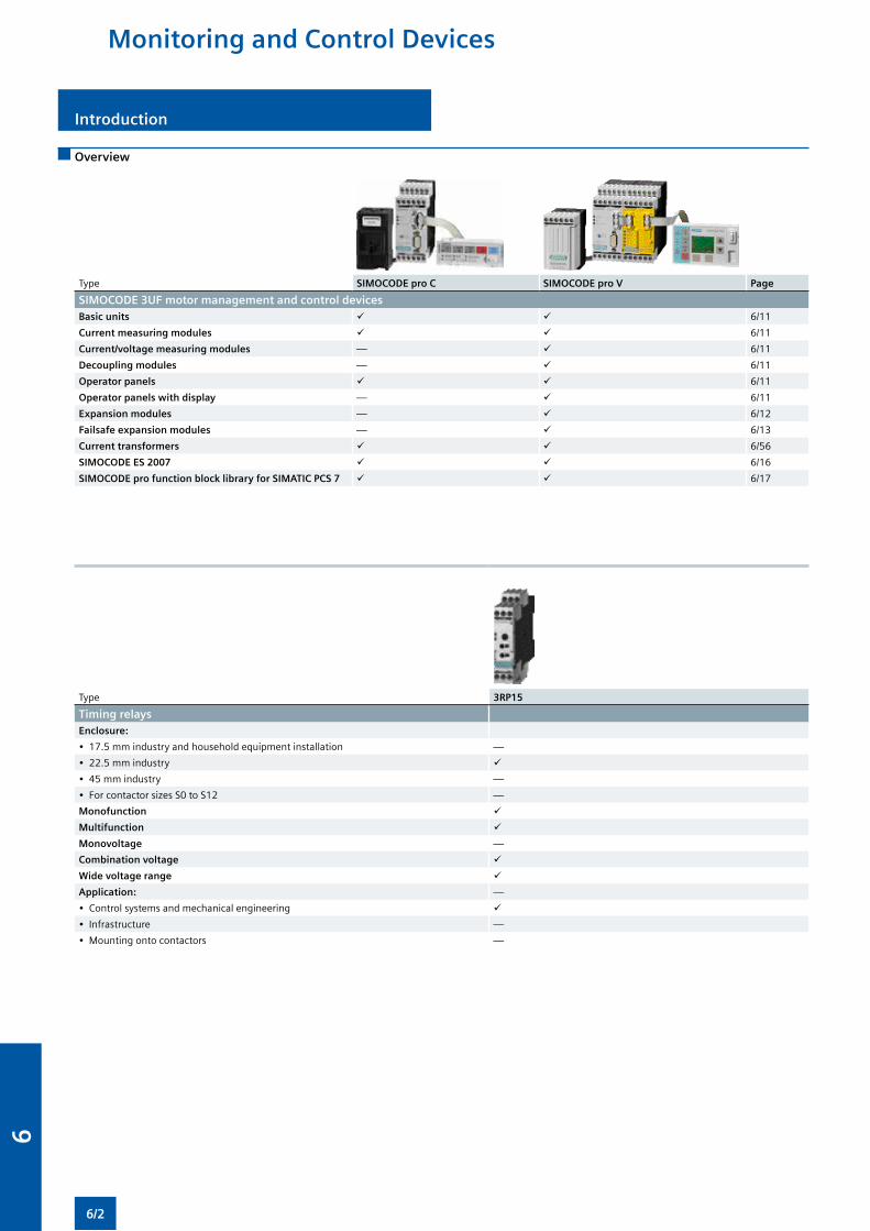
Overview
Type SIMOCODE pro C SIMOCODE pro V Page
SIMOCODE 3UF motor management and control devicesBasic units 6/11
Current measuring modules 6/11
Current/voltage measuring modules — 6/11
Decoupling modules — 6/11
Operator panels 6/11
Operator panels with display — 6/11
Expansion modules — 6/12
Failsafe expansion modules — 6/13
Current transformers 6/56
SIMOCODE ES 2007 6/16
SIMOCODE pro function block library for SIMATIC PCS 7 6/17
Type 3RP15
Timing relaysEnclosure:
• 17.5 mm industry and household equipment installation —
• 22.5 mm industry
• 45 mm industry —
• For contactor sizes S0 to S12 —
Monofunction
Multifunction
Monovoltage —
Combination voltage
Wide voltage range
Application: —
• Control systems and mechanical engineering
• Infrastructure —
• Mounting onto contactors —
Introduction
Monitoring and Control Devices
6/2
6
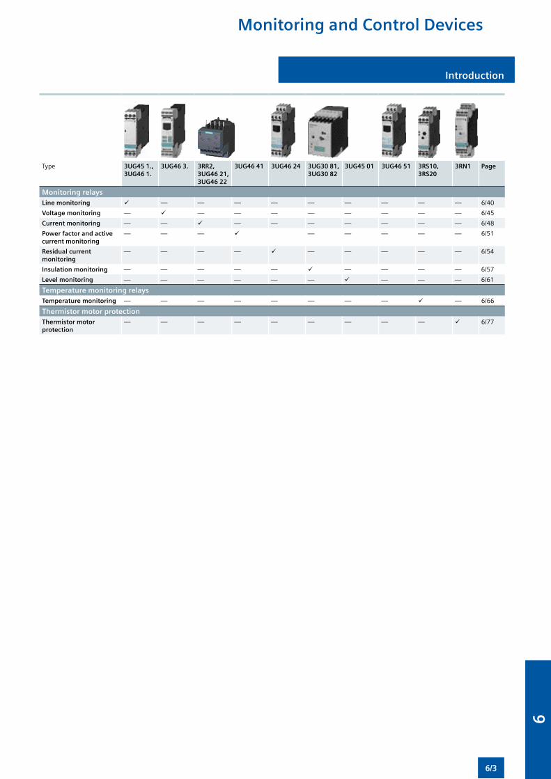
Introduction
Type 3UG45 1., 3UG46 1.
3UG46 3. 3RR2,3UG46 21,3UG46 22
3UG46 41 3UG46 24 3UG30 81,3UG30 82
3UG45 01 3UG46 51 3RS10, 3RS20
3RN1 Page
Monitoring relaysLine monitoring — — — — — — — — — 6/40
Voltage monitoring — — — — — — — — — 6/45
Current monitoring — — — — — — — — — 6/48
Power factor and active current monitoring
— — — — — — — — 6/51
Residual current monitoring
— — — — — — — — — 6/54
Insulation monitoring — — — — — — — — — 6/57
Level monitoring — — — — — — — — — 6/61
Temperature monitoring relaysTemperature monitoring — — — — — — — — — 6/66
Thermistor motor protectionThermistor motor protection
— — — — — — — — — 6/77
Monitoring and Control Devices
6/3
6
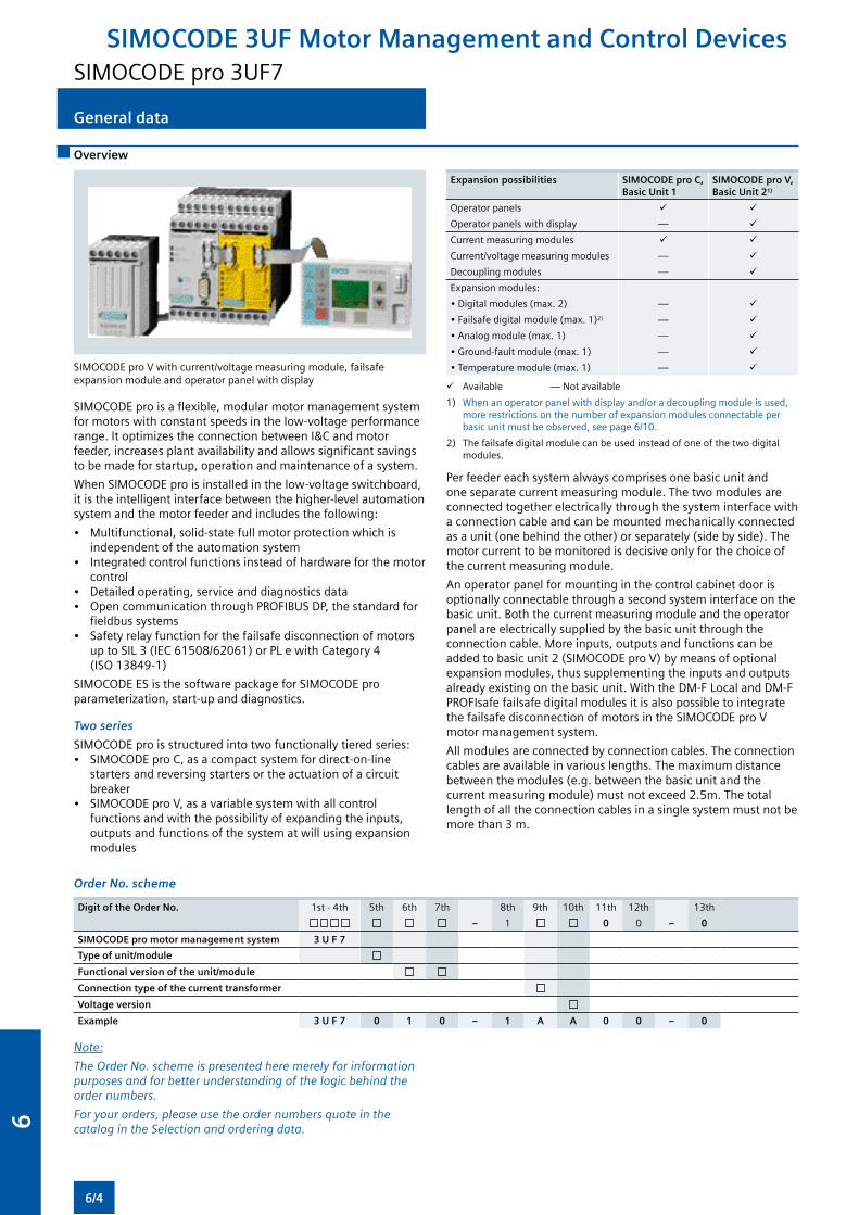
Overview
General data
SIMOCODE pro V with current/voltage measuring module, failsafe expansion module and operator panel with display
SIMOCODE pro is a flexible, modular motor management system for motors with constant speeds in the low-voltage performance range. It optimizes the connection between I&C and motor feeder, increases plant availability and allows significant savings to be made for startup, operation and maintenance of a system.
When SIMOCODE pro is installed in the low-voltage switchboard, it is the intelligent interface between the higher-level automation system and the motor feeder and includes the following:
• Multifunctional, solid-state full motor protection which is independent of the automation system
• Integrated control functions instead of hardware for the motor control
• Detailed operating, service and diagnostics data• Open communication through PROFIBUS DP, the standard for
fieldbus systems• Safety relay function for the failsafe disconnection of motors
up to SIL 3 (IEC 61508/62061) or PL e with Category 4 (ISO 13849-1)
SIMOCODE ES is the software package for SIMOCODE pro parameterization, start-up and diagnostics.
Two series
SIMOCODE pro is structured into two functionally tiered series:• SIMOCODE pro C, as a compact system for direct-on-line
starters and reversing starters or the actuation of a circuit breaker
• SIMOCODE pro V, as a variable system with all control functions and with the possibility of expanding the inputs, outputs and functions of the system at will using expansion modules
Expansion possibilities SIMOCODE pro C, Basic Unit 1
SIMOCODE pro V, Basic Unit 21)
Operator panels
Operator panels with display —
Current measuring modules
Current/voltage measuring modules —
Decoupling modules —
Expansion modules:
• Digital modules (max. 2) —
• Failsafe digital module (max. 1)2) —
• Analog module (max. 1) —
• Ground-fault module (max. 1) —
• Temperature module (max. 1) —
Available — Not available
1) When an operator panel with display and/or a decoupling module is used, more restrictions on the number of expansion modules connectable per basic unit must be observed, see page 6/10.
2) The failsafe digital module can be used instead of one of the two digital modules.
Per feeder each system always comprises one basic unit and one separate current measuring module. The two modules are connected together electrically through the system interface with a connection cable and can be mounted mechanically connected as a unit (one behind the other) or separately (side by side). The motor current to be monitored is decisive only for the choice of the current measuring module.
An operator panel for mounting in the control cabinet door is optionally connectable through a second system interface on the basic unit. Both the current measuring module and the operator panel are electrically supplied by the basic unit through the connection cable. More inputs, outputs and functions can be added to basic unit 2 (SIMOCODE pro V) by means of optional expansion modules, thus supplementing the inputs and outputs already existing on the basic unit. With the DM-F Local and DM-F PROFIsafe failsafe digital modules it is also possible to integrate the failsafe disconnection of motors in the SIMOCODE pro V motor management system.
All modules are connected by connection cables. The connection cables are available in various lengths. The maximum distance between the modules (e.g. between the basic unit and the current measuring module) must not exceed 2.5m. The total length of all the connection cables in a single system must not be more than 3 m.
Order No. scheme
Digit of the Order No. 1st - 4th 5th 6th 7th 8th 9th 10th 11th 12th 13th
– 1 0 0 – 0
SIMOCODE pro motor management system 3 U F 7
Type of unit/module
Functional version of the unit/module
Connection type of the current transformer
Voltage version
Example 3 U F 7 0 1 0 – 1 A A 0 0 – 0
Note:
The Order No. scheme is presented here merely for information purposes and for better understanding of the logic behind the order numbers.
For your orders, please use the order numbers quote in the catalog in the Selection and ordering data.
SIMOCODE 3UF Motor Management and Control DevicesSIMOCODE pro 3UF7
6/4
6

General data
Benefits
General customer benefits
• Integrating the whole motor feeder into the process control by means of a bus significantly reduces the wiring outlay between the motor feeder and PLC
• Decentralization of the automated processes by means of configurable control and monitoring functions in the feeder saves resources in the automation system and ensures full functionality and protection of the feeder even if the I&C or bus system fails
• The acquisition and monitoring of operational, service and diagnostics data in the feeder and process control system increases plant availability as well as maintenance and service-friendliness
• The high degree of modularity allows users to perfectly implement their plant-specific requirements for each motor feeder
• The SIMOCODE pro system offers functionally graded and space-saving solutions for each customer application
• The replacement of the control circuit hardware with integrated control functions decreases the number of hardware components and wiring required and in this way limits stock keeping costs and potential wiring errors
• The use of solid-state full motor protection permits better utilization of the motors and ensures long-term stability of the tripping characteristic and reliable tripping even after years of service
Multifunctional, solid-state full motor protection for rated motor currents up to 820 A
SIMOCODE pro offers comprehensive protection of the motor feeder by means of a combination of different, multi-step and delayable protection and monitoring functions:
• Inverse-time delayed solid-state overload protection (CLASS 5 to 40)
• Thermistor motor protection• Phase failure/unbalance protection• Stall protection• Monitoring of adjustable limit values for the motor current• Voltage and power monitoring• Monitoring of the power factor (motor idling/load shedding)• Ground-fault monitoring• Temperature monitoring, e.g. over PT100/PT1000• Monitoring of operating hours, downtime and number of
starts etc.
Recording of measuring curves
SIMOCODE pro can record measuring curves and therefore is able, for example, to present the progression of motor current during motor start-up.
Flexible motor control implemented with integrated control functions (instead of comprehensive hardware interlocks)
Many predefined motor control functions have already been integrated into SIMOCODE pro, including all necessary logic operations and interlocks:
• Overload relays• Direct-on-line and reversing starters• Wye/delta starters (also with direction reversal)• Two speeds, motors with separate windings (pole-changing
switch); also with direction reversal • Two speeds, motors with separate Dahlander windings (also
with direction reversal) • Positioner actuation • Solenoid valve actuation • Actuation of a circuit breaker• Soft starter actuation (also with direction reversal)
These control functions are predefined in SIMOCODE pro and can be freely assigned to the inputs and outputs of the device (including PROFIBUS DP).
These predefined control functions can also be flexibly adapted to each customized configuration of a motor feeder by means of freely configurable logic modules (truth tables, counters, timers, edge evaluation, etc.) and with the help of standard functions (power failure monitoring, emergency start, external faults, etc.), without additional auxiliary relays being necessary in the control circuit.
SIMOCODE pro makes a lot of additional hardware and wiring in the control circuit unnecessary which results in a high level of standardization of the motor feeder in terms of its design and circuit diagrams.
Detailed operational, service and diagnostics data
SIMOCODE pro makes different operational, service and diagnostics data available and helps to detect potential faults in time and to prevent them by means of preventative measures. In the event of a malfunction, a fault can be diagnosed, localized and rectified very quickly – there are no or very short downtimes.
Operating data• Motor switching state derived from the current flow in the
main circuit• All phase currents• All phase voltages and phase-to-phase voltages• Active power, apparent power and power factor• Phase unbalance and phase sequence• Time to trip• Motor temperature• Remaining cooling time etc.
Service data• Motor operating hours• Motor stop times• Number of motor starts• Number of overload trips• Interval for compulsory testing of the enabling circuits• Consumed power• Internal comments stored in the device etc.
Diagnostics data• Numerous detailed early warning and fault messages• Internal device fault logging with time stamp• Time stamping of freely selectable status, alarm or fault
messages etc.
Easy operation and diagnostics
Operator panelsThe operator panel is used to control the motor feeder and can replace all conventional pushbuttons and indicator lights to save space. It makes SIMOCODE pro or the feeder directly operable in the control cabinet. It features all the status LEDs available on the basic unit and externalizes the system interface for simple parameterization or diagnosis on a PC/PG.
Operator panels with displayAs an alternative to the 3UF7 20 standard operator panel for SIMOCODE pro V there is also an operator panel with display: the 3UF7 21 is thus able in addition to indicate current measured values, operational and diagnostics data or status information of the motor feeder at the control cabinet. The pushbuttons of the operator panel can be used to control the motor while at the same time the display indicates current measured values, status information, fault messages or the device-internal fault protocol. Using the display settings each user can select for himself how the measured values are presented as standard and how the displayed unit is converted (e.g. °C -> °F).
SIMOCODE 3UF Motor Management and Control DevicesSIMOCODE pro 3UF7
6/5
6
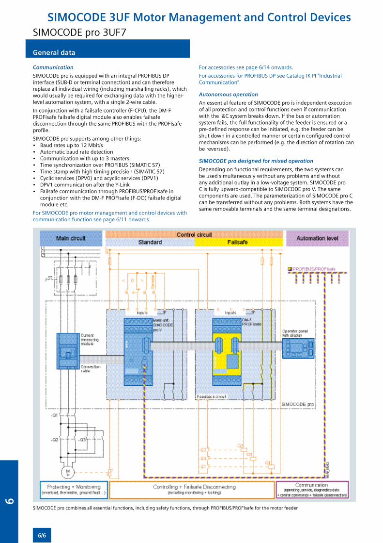
General data
Communication
SIMOCODE pro is equipped with an integral PROFIBUS DP interface (SUB-D or terminal connection) and can therefore replace all individual wiring (including marshalling racks), which would usually be required for exchanging data with the higher-level automation system, with a single 2-wire cable.
In conjunction with a failsafe controller (F-CPU), the DM-F PROFIsafe failsafe digital module also enables failsafe disconnection through the same PROFIBUS with the PROFIsafe profile.
SIMOCODE pro supports among other things: • Baud rates up to 12 Mbit/s • Automatic baud rate detection• Communication with up to 3 masters• Time synchronization over PROFIBUS (SIMATIC S7)• Time stamp with high timing precision (SIMATIC S7)• Cyclic services (DPV0) and acyclic services (DPV1)• DPV1 communication after the Y-Link• Failsafe communication through PROFIBUS/PROFIsafe in
conjunction with the DM-F PROFIsafe (F-DO) failsafe digital module etc.
For SIMOCODE pro motor management and control devices with communication function see page 6/11 onwards.
For accessories see page 6/14 onwards.
For accessories for PROFIBUS DP see Catalog IK PI “Industrial Communication”.
Autonomous operation
An essential feature of SIMOCODE pro is independent execution of all protection and control functions even if communication with the I&C system breaks down. If the bus or automation system fails, the full functionality of the feeder is ensured or a pre-defined response can be initiated, e.g. the feeder can be shut down in a controlled manner or certain configured control mechanisms can be performed (e.g. the direction of rotation can be reversed).
SIMOCODE pro designed for mixed operation
Depending on functional requirements, the two systems can be used simultaneously without any problems and without any additional outlay in a low-voltage system. SIMOCODE pro C is fully upward-compatible to SIMOCODE pro V. The same components are used. The parameterization of SIMOCODE pro C can be transferred without any problems. Both systems have the same removable terminals and the same terminal designations.
SIMOCODE pro combines all essential functions, including safety functions, through PROFIBUS/PROFIsafe for the motor feeder
SIMOCODE 3UF Motor Management and Control DevicesSIMOCODE pro 3UF7
6/6
6
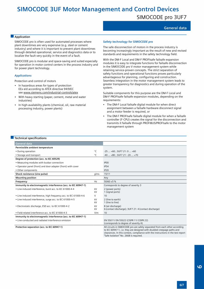
General data
Application
SIMOCODE pro is often used for automated processes where plant downtimes are very expensive (e.g. steel or cement industry) and where it is important to prevent plant downtimes through detailed operational, service and diagnostics data or to localize the fault very quickly in the event of a fault.
SIMOCODE pro is modular and space-saving and suited especially for operation in motor control centers in the process industry and for power plant technology.
Applications
Protection and control of motors
• In hazardous areas for types of protection EEx e/d according to ATEX directive 94/9/EC see www.siemens.com/industrial-controls/atex
• With heavy starting (paper, cement, metal and water industries)
• In high-availability plants (chemical, oil, raw material processing industry, power plants)
Safety technology for SIMOCODE pro
The safe disconnection of motors in the process industry is becoming increasingly important as the result of new and revised standards and requirements in the safety technology field.
With the DM-F Local and DM-F PROFIsafe failsafe expansion modules it is easy to integrate functions for failsafe disconnection in the SIMOCODE pro V motor management system while retaining service-proven concepts. The strict separation of safety functions and operational functions proves particularly advantageous for planning, configuring and construction. Seamless integration in the motor management system leads to greater transparency for diagnostics and during operation of the system.
Suitable components for this purpose are the DM-F Local and DM-F PROFIsafe failsafe expansion modules, depending on the requirements:
• The DM-F Local failsafe digital module for when direct assignment between a failsafe hardware disconnect signal and a motor feeder is required, or
• The DM-F PROFIsafe failsafe digital module for when a failsafe controller (F-CPU) creates the signal for the disconnection and transmits it failsafe through PROFIBUS/PROFIsafe to the motor management system
Technical specifications
General dataPermissible ambient temperature
• During operation °C -25 ... +60 ; 3UF7 21: 0 ... +60
• Storage and transport °C -40 ... +80 ; 3UF7 21: -20 ... +70
Degree of protection (acc. to IEC 60529)
• Measuring modules with busbar connection IP00
• Operator panel (front) and door adapter (front) with cover IP54
• Other components IP20
Shock resistance (sine pulse) g/ms 15/11
Mounting position Any
Frequency Hz 50/60 ±5 %
Immunity to electromagnetic interference (acc. to IEC 60947-1) Corresponds to degree of severity 3
• Line-induced interference, burst acc. to IEC 61000-4-4 kVkV
2 (power ports)1 (signal ports)
• Line-induced interference, high frequency acc. to IEC 61000-4-6 V 10
• Line-induced interference, surge acc. to IEC 61000-4-5 kVkV
2 (line to earth)1 (line to line)
• Electrostatic discharge, ESD acc. to IEC 61000-4-2 kVkV
8 (air discharge)6 (contact discharge); 3UF7 21: 4 (contact discharge)
• Field-related interference acc. to IEC 61000-4-3 V/m 10
Immunity to electromagnetic interference (acc. to IEC 60947-1)
• Line-conducted and radiated interference emission EN 55011/ EN 55022 (CISPR 11/ CISPR 22)(corresponds to degree of severity A)
Protective separation (acc. to IEC 60947-1) All circuits in SIMOCODE pro are safely separated from each other according to IEC 60947-1, i.e. they are designed with doubled creepage paths and clearances. In this context, compliance with the instructions in the test report “Safe Isolation” No. 2668 is required.
SIMOCODE 3UF Motor Management and Control DevicesSIMOCODE pro 3UF7
6/7
6
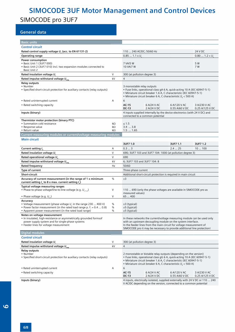
General data
Basic units
Control circuitRated control supply voltage Us (acc. to EN 61131-2) 110 ... 240 AC/DC; 50/60 Hz 24 V DC
Operating range 0.85 ... 1.1 x Us 0.80 ... 1.2 × Us
Power consumption• Basic Unit 1 (3UF7 000)• Basic Unit 2 (3UF7 010) incl. two expansion modules connected to
Basic Unit 2
7 VA/5 W10 VA/7 W
5 W7 W
Rated insulation voltage Ui V 300 (at pollution degree 3)
Rated impulse withstand voltage Uimp kV 4
Relay outputs• Number• Specified short-circuit protection for auxiliary contacts (relay outputs)
3 monostable relay outputs• Fuse links, operational class gA 6 A, quick-acting 10 A (IEC 60947-5-1)• Miniature circuit breaker 1.6 A, C characteristic (IEC 60947-5-1)• Miniature circuit breaker 6 A, C characteristic (Ik < 500 A)
• Rated uninterrupted current A 6
• Rated switching capacity AC-15 DC-13
6 A/24 V AC 2 A/24 V DC
6 A/120 V AC 0.55 A/60 V DC
3 A/230 V AC0.25 A/125 V DC
Inputs (binary) 4 inputs supplied internally by the device electronics (with 24 V DC) and connected to a common potential
Thermistor motor protection (binary PTC)• Summation cold resistance• Response value• Return value
kΩkΩkΩ
≤ 1.53.4 ... 3.81.5 ... 1.65
Current measuring modules or current/voltage measuring modules
Main circuit3UF7 1.0 3UF7 1.1 3UF7 1.2
Current setting Ie A 0.3 ... 3 2.4 ... 25 10 ... 100
Rated insulation voltage Ui V 690; 3UF7 103 and 3UF7 104: 1000 (at pollution degree 3)
Rated operational voltage Ue V 690
Rated impulse withstand voltage Uimp kV 6; 3UF7 103 and 3UF7 104: 8
Rated frequency Hz 50/60
Type of current Three-phase current
Short-circuit Additional short-circuit protection is required in main circuit
Accuracy of current measurement (in the range of 1 x minimum current setting Iu to 8 x max. current setting Io)
% ±3
Typical voltage measuring ranges• Phase-to-phase voltage/line-to-line-voltage (e.g. UL1 L2)
• Phase voltage (e.g. UL1)
V
V
110 ... 690 (only the phase voltages are available in SIMOCODE pro as measured values)65 ... 400
Accuracy• Voltage measurement (phase voltage UL in the range 230 ... 400 V)• Power factor measurement (in the rated load range p. f. = 0.4 ... 0.8)• Apparent power measurement (in the rated load range)
%%%
±3 (typical)±5 (typical)±5 (typical)
Notes on voltage measurement• In insulated, high-resistance or asymmetrically grounded formsof
power supply system and for single-phase systems• Feeder lines for voltage measurement
In these networks the current/voltage measuring module can be used only with an upstream decoupling module on the system interface.In the feeder lines from the main circuit for voltage measurement of SIMOCODE pro it may be necessary to provide additional line protection!
Digital modules
Control circuitRated insulation voltage Ui V 300 (at pollution degree 3)
Rated impulse withstand voltage Uimp kV 4
Relay outputs• Number• Specified short-circuit protection for auxiliary contacts (relay outputs)
2 monostable or bistable relay outputs (depending on the version)• Fuse links, operational class gG 6 A, quick-acting 10 A (IEC 60947-5-1)• Miniature circuit breaker 1.6 A, C characteristic (IEC 60947-5-1)• Miniature circuit breaker 6 A, C characteristic (Ik < 500 A)
• Rated uninterrupted current A 6
• Rated switching capacity AC-15 DC-13
6 A/24 V AC 2 A/24 V DC
6 A/120 V AC 0.55 A/60 V DC
3 A/230 V AC 0.25 A/125 V DC
Inputs (binary) 4 inputs, electrically isolated, supplied externally with 24 V DC or 110 ... 240 V AC/DC depending on the version, connected to a common potential
SIMOCODE 3UF Motor Management and Control DevicesSIMOCODE pro 3UF7
6/8
6
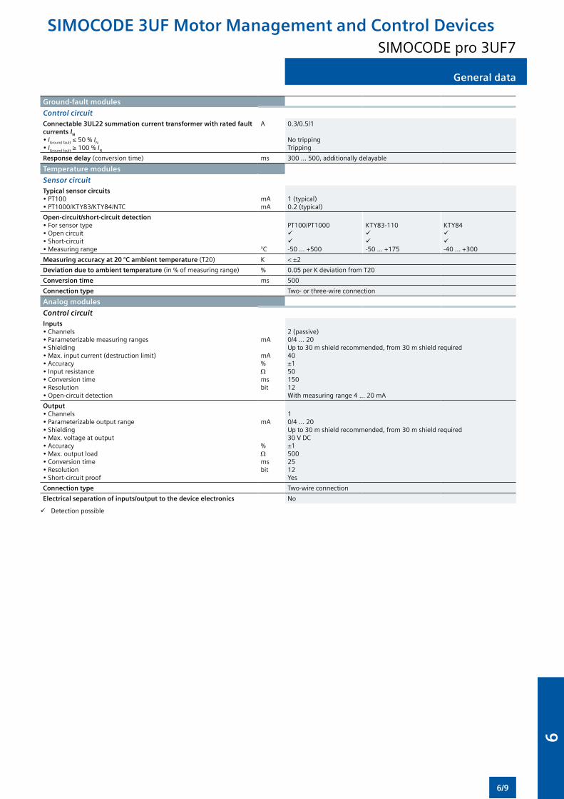
General data
Ground-fault modules
Control circuitConnectable 3UL22 summation current transformer with rated fault currents IN • IGround fault ≤ 50 % IN
• IGround fault ≥ 100 % IN
A 0.3/0.5/1
No trippingTripping
Response delay (conversion time) ms 300 ... 500, additionally delayable
Temperature modules
Sensor circuitTypical sensor circuits• PT100• PT1000/KTY83/KTY84/NTC
mAmA
1 (typical)0.2 (typical)
Open-circuit/short-circuit detection• For sensor type• Open circuit• Short-circuit• Measuring range °C
PT100/PT1000-50 ... +500
KTY83-110-50 ... +175
KTY84-40 ... +300
Measuring accuracy at 20 °C ambient temperature (T20) K < ±2
Deviation due to ambient temperature (in % of measuring range) % 0.05 per K deviation from T20
Conversion time ms 500
Connection type Two- or three-wire connection
Analog modules
Control circuitInputs• Channels• Parameterizable measuring ranges• Shielding• Max. input current (destruction limit)• Accuracy• Input resistance• Conversion time• Resolution• Open-circuit detection
mA
mA%Ωmsbit
2 (passive)0/4 ... 20Up to 30 m shield recommended, from 30 m shield required40±15015012With measuring range 4 ... 20 mA
Output• Channels• Parameterizable output range• Shielding• Max. voltage at output• Accuracy• Max. output load• Conversion time• Resolution• Short-circuit proof
mA %Ωmsbit
10/4 ... 20Up to 30 m shield recommended, from 30 m shield required30 V DC±15002512Yes
Connection type Two-wire connection
Electrical separation of inputs/output to the device electronics No
Detection possible
SIMOCODE 3UF Motor Management and Control DevicesSIMOCODE pro 3UF7
6/9
6
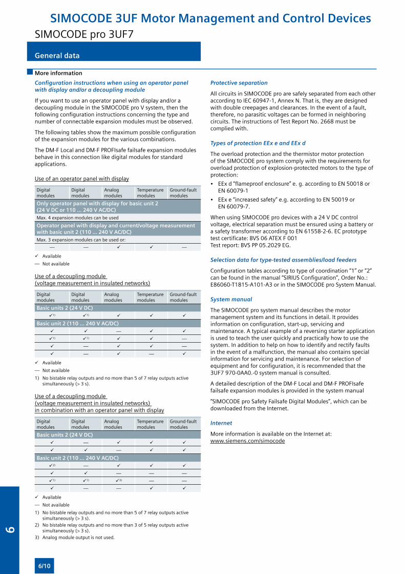
General data
More information
Configuration instructions when using an operator panel with display and/or a decoupling module
If you want to use an operator panel with display and/or a decoupling module in the SIMOCODE pro V system, then the following configuration instructions concerning the type and number of connectable expansion modules must be observed.
The following tables show the maximum possible configuration of the expansion modules for the various combinations.
The DM-F Local and DM-F PROFIsafe failsafe expansion modules behave in this connection like digital modules for standard applications.
Use of an operator panel with display
Digital modules
Digital modules
Analog modules
Temperature modules
Ground-fault modules
Only operator panel with display for basic unit 2 (24 V DC or 110 ... 240 V AC/DC)Max. 4 expansion modules can be used
Operator panel with display and current/voltage measurement with basic unit 2 (110 ... 240 V AC/DC)Max. 3 expansion modules can be used or:
— — —
Available
— Not available
Use of a decoupling module (voltage measurement in insulated networks)
Digital modules
Digital modules
Analog modules
Temperature modules
Ground-fault modules
Basic units 2 (24 V DC)1) 1)
Basic unit 2 (110 ... 240 V AC/DC) —
1) 1) —
— —
— —
Available
— Not available
1) No bistable relay outputs and no more than 5 of 7 relay outputs active simultaneously (> 3 s).
Use of a decoupling module (voltage measurement in insulated networks) in combination with an operator panel with display
Digital modules
Digital modules
Analog modules
Temperature modules
Ground-fault modules
Basic units 2 (24 V DC) —
—
Basic unit 2 (110 ... 240 V AC/DC)2) —
— — —
1) 1) 3) — —
— —
Available
— Not available
1) No bistable relay outputs and no more than 5 of 7 relay outputs active simultaneously (> 3 s).
2) No bistable relay outputs and no more than 3 of 5 relay outputs active simultaneously (> 3 s).
3) Analog module output is not used.
Protective separation
All circuits in SIMOCODE pro are safely separated from each other according to IEC 60947-1, Annex N. That is, they are designed with double creepages and clearances. In the event of a fault, therefore, no parasitic voltages can be formed in neighboring circuits. The instructions of Test Report No. 2668 must be complied with.
Types of protection EEx e and EEx d
The overload protection and the thermistor motor protection of the SIMOCODE pro system comply with the requirements for overload protection of explosion-protected motors to the type of protection:
• EEx d “flameproof enclosure” e. g. according to EN 50018 or EN 60079-1
• EEx e “increased safety” e.g. according to EN 50019 or EN 60079-7.
When using SIMOCODE pro devices with a 24 V DC control voltage, electrical separation must be ensured using a battery or a safety transformer according to EN 61558-2-6. EC prototype test certificate: BVS 06 ATEX F 001 Test report: BVS PP 05.2029 EG.
Selection data for type-tested assemblies/load feeders
Configuration tables according to type of coordination “1” or “2” can be found in the manual “SIRIUS Configuration”, Order No.: E86060-T1815-A101-A3 or in the SIMOCODE pro System Manual.
System manual
The SIMOCODE pro system manual describes the motor management system and its functions in detail. It provides information on configuration, start-up, servicing and maintenance. A typical example of a reversing starter application is used to teach the user quickly and practically how to use the system. In addition to help on how to identify and rectify faults in the event of a malfunction, the manual also contains special information for servicing and maintenance. For selection of equipment and for configuration, it is recommended that the 3UF7 970-0AA0.-0 system manual is consulted.
A detailed description of the DM-F Local and DM-F PROFIsafe failsafe expansion modules is provided in the system manual
“SIMOCODE pro Safety Failsafe Digital Modules”, which can be downloaded from the Internet.
Internet
More information is available on the Internet at: www.siemens.com/simocode
SIMOCODE 3UF Motor Management and Control DevicesSIMOCODE pro 3UF7
6/10
6
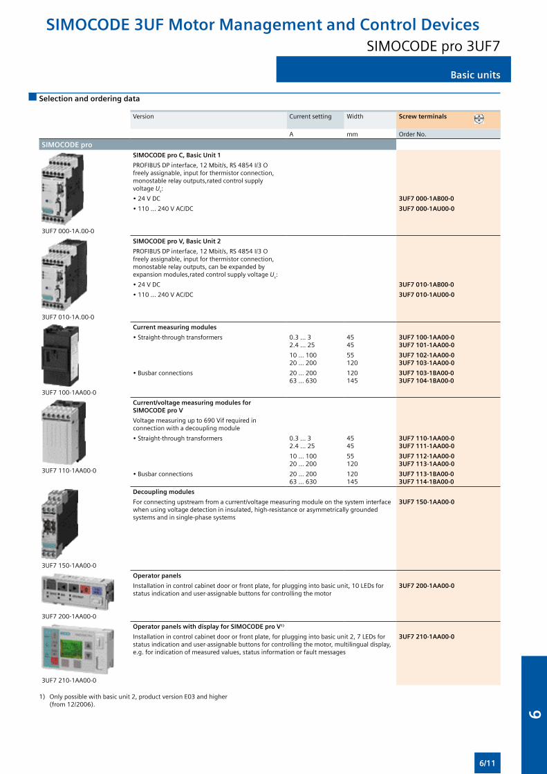
Basic units
Selection and ordering data
Version Current setting Width Screw terminals
A mm Order No.
SIMOCODE pro
3UF7 000-1A.00-0
SIMOCODE pro C, Basic Unit 1
PROFIBUS DP interface, 12 Mbit/s, RS 4854 I/3 O freely assignable, input for thermistor connection, monostable relay outputs,rated control supply voltage Us:
• 24 V DC 3UF7 000-1AB00-0
• 110 ... 240 V AC/DC 3UF7 000-1AU00-0
3UF7 010-1A.00-0
SIMOCODE pro V, Basic Unit 2
PROFIBUS DP interface, 12 Mbit/s, RS 4854 I/3 O freely assignable, input for thermistor connection, monostable relay outputs, can be expanded by expansion modules,rated control supply voltage Us:
• 24 V DC 3UF7 010-1AB00-0
• 110 ... 240 V AC/DC 3UF7 010-1AU00-0
3UF7 100-1AA00-0
Current measuring modules
• Straight-through transformers 0.3 ... 32.4 ... 25
4545
3UF7 100-1AA00-03UF7 101-1AA00-0
10 ... 10020 ... 200
55120
3UF7 102-1AA00-03UF7 103-1AA00-0
• Busbar connections 20 ... 20063 ... 630
120145
3UF7 103-1BA00-03UF7 104-1BA00-0
3UF7 110-1AA00-0
Current/voltage measuring modules for SIMOCODE pro V
Voltage measuring up to 690 Vif required in connection with a decoupling module
• Straight-through transformers 0.3 ... 32.4 ... 25
4545
3UF7 110-1AA00-03UF7 111-1AA00-0
10 ... 10020 ... 200
55120
3UF7 112-1AA00-03UF7 113-1AA00-0
• Busbar connections 20 ... 20063 ... 630
120145
3UF7 113-1BA00-03UF7 114-1BA00-0
3UF7 150-1AA00-0
Decoupling modules
For connecting upstream from a current/voltage measuring module on the system interface when using voltage detection in insulated, high-resistance or asymmetrically grounded systems and in single-phase systems
3UF7 150-1AA00-0
3UF7 200-1AA00-0
Operator panels
Installation in control cabinet door or front plate, for plugging into basic unit, 10 LEDs for status indication and user-assignable buttons for controlling the motor
3UF7 200-1AA00-0
3UF7 210-1AA00-0
Operator panels with display for SIMOCODE pro V1)
Installation in control cabinet door or front plate, for plugging into basic unit 2, 7 LEDs for status indication and user-assignable buttons for controlling the motor, multilingual display, e.g. for indication of measured values, status information or fault messages
3UF7 210-1AA00-0
1) Only possible with basic unit 2, product version E03 and higher (from 12/2006).
SIMOCODE 3UF Motor Management and Control DevicesSIMOCODE pro 3UF7
6/11
6
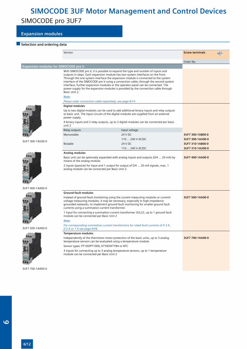
Expansion modules
Selection and ordering data
Version Screw terminals
Order No.
Expansion modules for SIMOCODE pro V With SIMOCODE pro V, it is possible to expand the type and number of inputs and outputs in steps. Each expansion module has two system interfaces on the front. Through the one system interface the expansion module is connected to the system interface of the SIMOCODE pro V using a connection cable; through the second system interface, further expansion modules or the operator panel can be connected. The power supply for the expansion modules is provided by the connection cable through Basic Unit 2.
Note:
Please order connection cable separately, see page 6/14.
3UF7 300-1AU00-0
Digital modules
Up to two digital modules can be used to add additional binary inputs and relay outputs to basic unit. The input circuits of the digital modules are supplied from an external power supply.
4 binary inputs and 2 relay outputs, up to 2 digital modules can be connected per basic unit 2
Relay outputs Input voltage
Monostable 24 V DC 3UF7 300-1AB00-0
110 ... 240 V AC/DC 3UF7 300-1AU00-0
Bistable 24 V DC 3UF7 310-1AB00-0
110 ... 240 V AC/DC 3UF7 310-1AU00-0
3UF7 400-1AA00-0
Analog modules
Basic unit can be optionally expanded with analog inputs and outputs (0/4 ... 20 mA) by means of the analog module.
2 inputs (passive) for input and 1 output for output of 0/4 ... 20 mA signals, max. 1 analog module can be connected per Basic Unit 2.
3UF7 400-1AA00-0
3UF7 500-1AA00-0
Ground-fault modules
Instead of ground-fault monitoring using the current measuring modules or current/voltage measuring modules, it may be necessary, especially in high-impedance grounded networks, to implement ground-fault monitoring for smaller ground fault currents using a summation current transformer.
1 input for connecting a summation current transformer 3UL22, up to 1 ground-fault module can be connected per Basic Unit 2
Note:
For corresponding summation current transformers for rated fault currents of 0.3 A, 0.5 A or 1 A see page 6/56.
3UF7 500-1AA00-0
3UF7 700-1AA00-0
Temperature modules
Independently of the thermistor motor protection of the basic units, up to 3 analog temperature sensors can be evaluated using a temperature module.
Sensor types: PT100/PT1000, KTY83/KTY84 or NTC
3 inputs for connecting up to 3 analog temperature sensors, up to 1 temperature module can be connected per Basic Unit 2
3UF7 700-1AA00-0
SIMOCODE 3UF Motor Management and Control DevicesSIMOCODE pro 3UF7
6/12
6
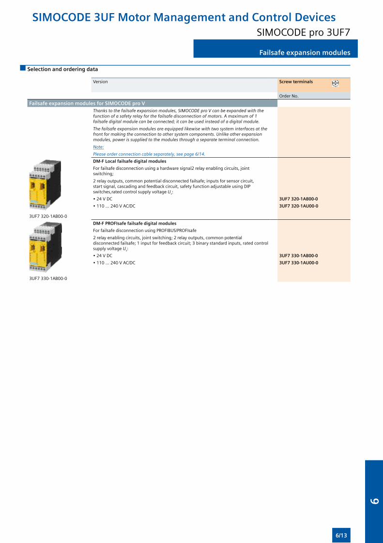
Failsafe expansion modules
Selection and ordering data
Version Screw terminals
Order No.
Failsafe expansion modules for SIMOCODE pro VThanks to the failsafe expansion modules, SIMOCODE pro V can be expanded with the function of a safety relay for the failsafe disconnection of motors. A maximum of 1 failsafe digital module can be connected; it can be used instead of a digital module.
The failsafe expansion modules are equipped likewise with two system interfaces at the front for making the connection to other system components. Unlike other expansion modules, power is supplied to the modules through a separate terminal connection.
Note:
Please order connection cable separately, see page 6/14.
3UF7 320-1AB00-0
DM-F Local failsafe digital modules
For failsafe disconnection using a hardware signal2 relay enabling circuits, joint switching;
2 relay outputs, common potential disconnected failsafe; inputs for sensor circuit, start signal, cascading and feedback circuit, safety function adjustable using DIP switches,rated control supply voltage Us:
• 24 V DC 3UF7 320-1AB00-0
• 110 ... 240 V AC/DC 3UF7 320-1AU00-0
3UF7 330-1AB00-0
DM-F PROFIsafe failsafe digital modules
For failsafe disconnection using PROFIBUS/PROFIsafe
2 relay enabling circuits, joint switching; 2 relay outputs, common potential disconnected failsafe; 1 input for feedback circuit; 3 binary standard inputs, rated control supply voltage Us:
• 24 V DC 3UF7 330-1AB00-0
• 110 ... 240 V AC/DC 3UF7 330-1AU00-0
SIMOCODE 3UF Motor Management and Control DevicesSIMOCODE pro 3UF7
6/13
6
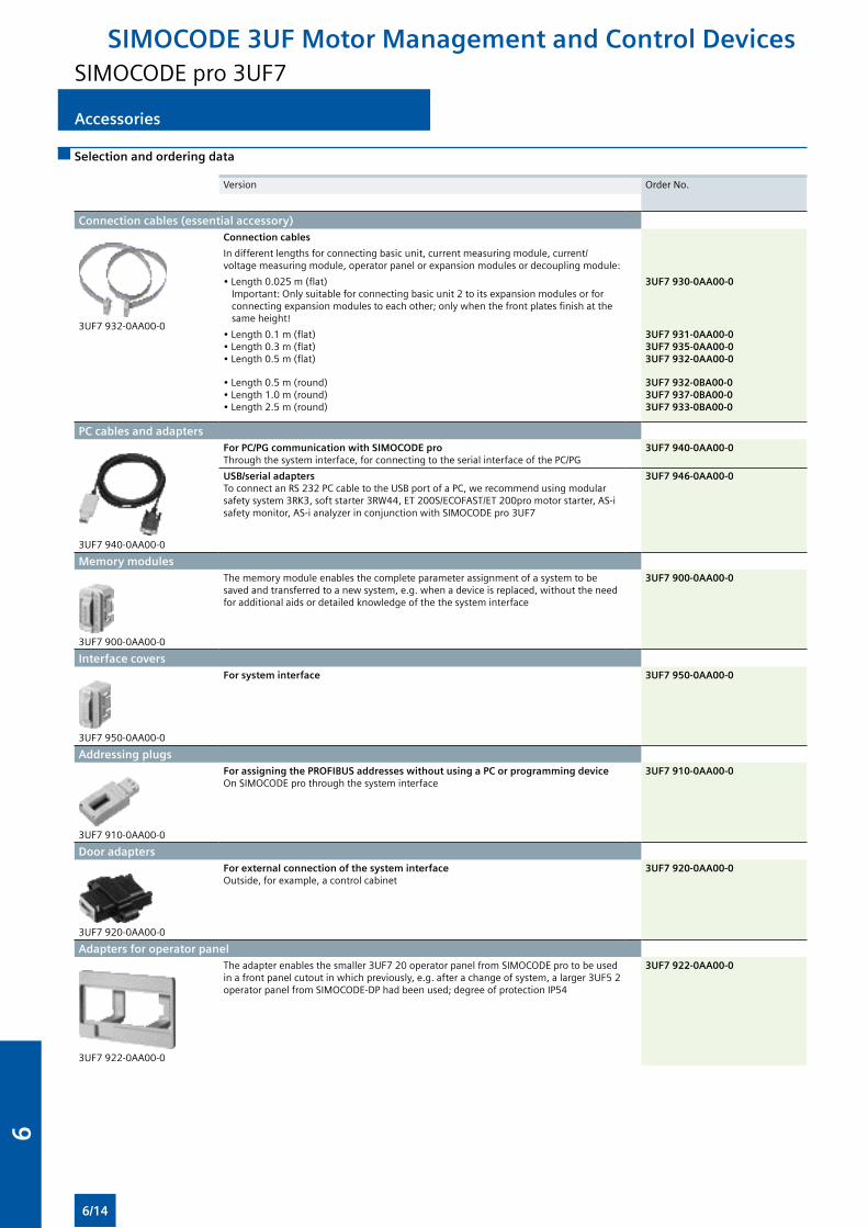
Accessories
Selection and ordering data
Version Order No.
Connection cables (essential accessory)
3UF7 932-0AA00-0
Connection cables
In different lengths for connecting basic unit, current measuring module, current/voltage measuring module, operator panel or expansion modules or decoupling module:
• Length 0.025 m (flat)Important: Only suitable for connecting basic unit 2 to its expansion modules or for connecting expansion modules to each other; only when the front plates finish at the same height!
3UF7 930-0AA00-0
• Length 0.1 m (flat)• Length 0.3 m (flat)• Length 0.5 m (flat)
3UF7 931-0AA00-03UF7 935-0AA00-03UF7 932-0AA00-0
• Length 0.5 m (round)• Length 1.0 m (round)• Length 2.5 m (round)
3UF7 932-0BA00-03UF7 937-0BA00-03UF7 933-0BA00-0
PC cables and adapters
3UF7 940-0AA00-0
For PC/PG communication with SIMOCODE proThrough the system interface, for connecting to the serial interface of the PC/PG
3UF7 940-0AA00-0
USB/serial adaptersTo connect an RS 232 PC cable to the USB port of a PC, we recommend using modular safety system 3RK3, soft starter 3RW44, ET 200S/ECOFAST/ET 200pro motor starter, AS-i safety monitor, AS-i analyzer in conjunction with SIMOCODE pro 3UF7
3UF7 946-0AA00-0
Memory modules
3UF7 900-0AA00-0
The memory module enables the complete parameter assignment of a system to be saved and transferred to a new system, e.g. when a device is replaced, without the need for additional aids or detailed knowledge of the the system interface
3UF7 900-0AA00-0
Interface covers
3UF7 950-0AA00-0
For system interface 3UF7 950-0AA00-0
Addressing plugs
3UF7 910-0AA00-0
For assigning the PROFIBUS addresses without using a PC or programming device On SIMOCODE pro through the system interface
3UF7 910-0AA00-0
Door adapters
3UF7 920-0AA00-0
For external connection of the system interfaceOutside, for example, a control cabinet
3UF7 920-0AA00-0
Adapters for operator panel
3UF7 922-0AA00-0
The adapter enables the smaller 3UF7 20 operator panel from SIMOCODE pro to be used in a front panel cutout in which previously, e.g. after a change of system, a larger 3UF5 2 operator panel from SIMOCODE-DP had been used; degree of protection IP54
3UF7 922-0AA00-0
SIMOCODE 3UF Motor Management and Control DevicesSIMOCODE pro 3UF7
6/14
6

Accessories
Version Order No.
Labeling strips
3UF7 925-0AA02-0
• For pushbuttons of the 3UF7 20 operator panel 3UF7 925-0AA00-0
• For pushbuttons of the 3UF7 21 operator panel with display 3UF7 925-0AA01-0
• For LEDs of the 3UF7 20 operator panel 3UF7 925-0AA02-0
Note: Pre-punched labeling strips for user-specific printing using the free inscription software “SIRIUS Label Designer” on a laser printer.
Note the software version!
Download from www.siemens.com/simocode
Push-in lugs
3RB19 00-0B
For screw fixing E.g. on mounting plate, 2 units required per device
• Can be used with 3UF7 1.0, 3UF7 1.1 and 3UF7 1.2 3RB19 00-0B
• Can be used with 3UF7 0, 3UF7 3, 3UF7 4, 3UF7 5 and 3UF7 7 3RP19 03
Terminal covers
3RT19 56-4EA1
3RT19 56-4EA2
Covers for cable lugs and busbar connections
• Length 100 mm, can be used for 3UF7 1.3-1BA00-0 3RT19 56-4EA1
• Length 120 mm, can be used for 3UF7 1.4-1BA00-0 3RT19 66-4EA1
Covers for box terminals
• Length 25 mm, can be used for 3UF7 1.3-1BA00-0 3RT19 56-4EA2
• Length 30 mm, can be used for 3UF7 1.4-1BA00-0 3RT19 66-4EA2
Covers for screw terminals Between contactor and current measuring module or current/voltage measuring module for direct mounting
• Can be used for 3UF7 1.3-1BA00-0 3RT19 56-4EA3
• Can be used for 3UF7 1.4-1BA00-0 3RT19 66-4EA3
Box terminal blocks
3RT19 5.-4G
For round and ribbon cables
• Up to 70 mm2, can be used for 3UF7 1.3-1BA00-0 3RT19 55-4G
• Up to 120 mm2, can be used for 3UF7 1.3-1BA00-0 3RT19 56-4G
• Up to 240 mm2, can be used for 3UF7 1.4-1BA00-0 3RT19 66-4G
Bus termination modulesWith separate supply voltage for terminating the bus following the last unit on the bus line.Supply voltage:
• 115/230 V AC 3UF1 900-1KA00
• 24 V DC 3UF1 900-1KB00
System manuals
3UF7 970-0AA01-0
SIMOCODE pro
With token fee, languages:
• German 3UF7 970-0AA01-0
• English 3UF7 970-0AA00-0
• French 3UF7 970-0AA02-0
Note:
The system manual “SIMOCODE pro Safety Failsafe Digital Modules” is available on the Internet at www.siemens.com/simocode.
SIMOCODE 3UF Motor Management and Control DevicesSIMOCODE pro 3UF7
6/15
6

Accessories
Version Order No.
SIMOCODE ES 2007 Basic
3ZS1 312-4CC10-0YA5
Floating license for one user
E-SW, software and documentation on CD, 3 languages (German/English/French), communication through system interface
• License key on USB stick, Class A 3ZS1 312-4CC10-0YA5
• License key download, Class A 3ZS1 312-4CE10-0YB5
SIMOCODE ES 2007 Standard
Floating license for one user
E-SW, software and documentation on CD, 3 languages (German/English/French), communication through system interface, integratedgraphics editor
• License key on USB stick, Class A 3ZS1 312-5CC10-0YA5
• License key download, Class A 3ZS1 312-5CE10-0YB5
Upgrade for SIMOCODE ES 2004 and later
Floating license for one user,E-SW, software and documentation on CD, license key on USB stick, Class A, 3 languages (German/English/French), communication through the system interface
3ZS1 312-5CC10-0YE5
Powerpack for SIMOCODE ES 2007 Basic
Floating license for one user,E-SW, license key on USB stick, Class A, 3 languages (German/English/French), communication through the system interface
3ZS1 312-5CC10-0YD5
Software Update Service
For 1 year with automatic extension, assuming the current software version is in use, E-SW, software and documentation on CD, communication through the system interface
3ZS1 312-5CC10-0YL5
SIMOCODE ES 2007 Premium
Floating license for one user
E-SW, software and documentation on CD, 3 languages (German/English/French), communication through PROFIBUS or system interface, integrated graphics editor, STEP7 Object Manager
• License key on USB stick, Class A 3ZS1 312-6CC10-0YA5
• License key download, Class A 3ZS1 312-6CE10-0YB5
Upgrade for SIMOCODE ES 2004 and later
Floating license for one user,E-SW, software and documentation on CD, license key on USB stick, Class A, 3 languages (German/English/French), communication through PROFIBUS or the system interface
3ZS1 312-6CC10-0YE5
Powerpack for SIMOCODE ES 2007 Standard
Floating license for one user,E-SW, license key on USB stick, Class A, 3 languages (German/English/French), communication through the PROFIBUS or the system interface
3ZS1 312-6CC10-0YD5
Software Update Service
For 1 year with automatic extension, assuming the current software version is in use, E-SW, software and documentation on CD, communication through PROFIBUS or the system interface
3ZS1 312-6CC10-0YL5
Please order PC cable separately, see page 6/14.
SIMOCODE 3UF Motor Management and Control DevicesSIMOCODE pro 3UF7
6/16
6

Accessories
Version Order No.
SIMOCODE pro function block library for SIMATIC PCS 7
3UF7 982-0AA00-0
Scope of supply: AS modules and faceplates for integrating SIMOCODE pro into the PCS 7 process control system
Engineering software for one engineering station (single license) including runtime software for execution of the AS module in an automation system (single license), German/English/French, Type of delivery: CD incl. electronic documentation
• For PCS 7 Version V 6.0 3UF7 982-0AA00-0
• For PCS 7 Version V 6.1 3UF7 982-0AA02-0
• For PCS 7 Version V 7.0 3UF7 982-0AA10-0
Runtime software For execution of the AS module in an automation system (single license), Type of delivery: license without software and documentation
• For PCS 7 Version V 6.x 3UF7 982-0AA01-0
• For PCS 7 Version V 7.x 3UF7 982-0AA11-0
Upgrade for the PCS 7 function block library SIMOCODE pro, V6.0 or V6.1 on Version SIMOCODE pro V7.0 for integrating SIMOCODE pro into the PCS 7 process control system, for PCS 7 Version V7.0 (single license), German/English/French, Type of delivery: CD incl. electronic documentation
3UF7 982-0AA13-0
SIMOCODE 3UF Motor Management and Control DevicesSIMOCODE pro 3UF7
6/17
6
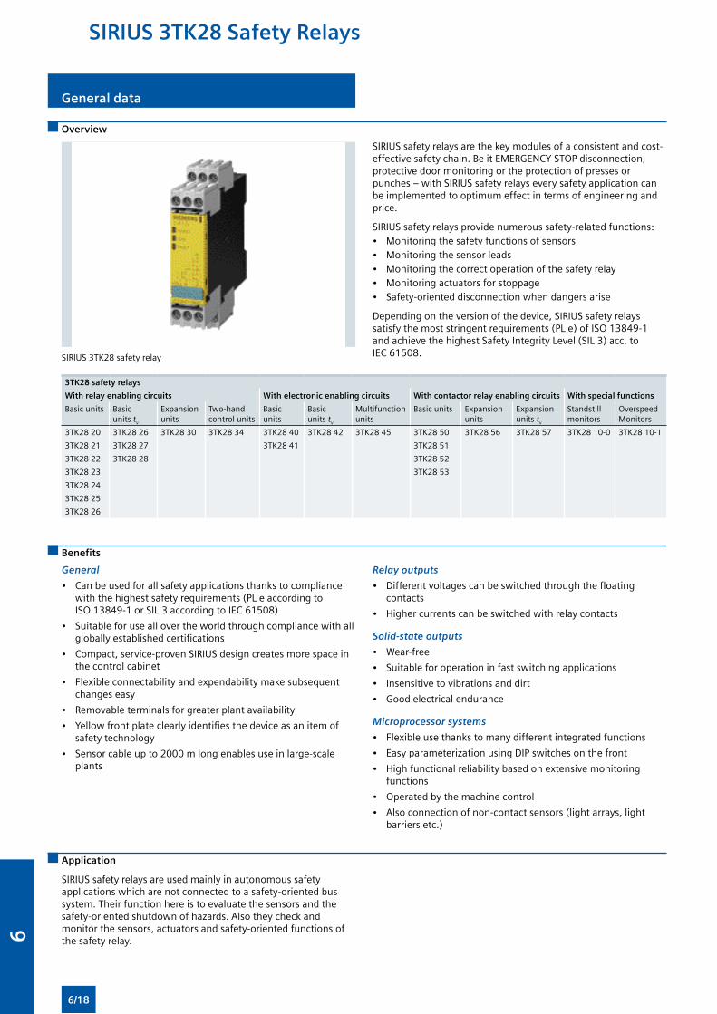
General data
Overview
SIRIUS 3TK28 safety relay
SIRIUS safety relays are the key modules of a consistent and cost-effective safety chain. Be it EMERGENCY-STOP disconnection, protective door monitoring or the protection of presses or punches – with SIRIUS safety relays every safety application can be implemented to optimum effect in terms of engineering and price.
SIRIUS safety relays provide numerous safety-related functions:• Monitoring the safety functions of sensors• Monitoring the sensor leads• Monitoring the correct operation of the safety relay• Monitoring actuators for stoppage• Safety-oriented disconnection when dangers arise
Depending on the version of the device, SIRIUS safety relays satisfy the most stringent requirements (PL e) of ISO 13849-1 and achieve the highest Safety Integrity Level (SIL 3) acc. to IEC 61508.
3TK28 safety relays
With relay enabling circuits With electronic enabling circuits With contactor relay enabling circuits With special functions
Basic units Basic units tv
Expansion units
Two-hand control units
Basic units
Basic units tv
Multifunction units
Basic units Expansion units
Expansion units tv
Standstill monitors
Overspeed Monitors
3TK28 20 3TK28 26 3TK28 30 3TK28 34 3TK28 40 3TK28 42 3TK28 45 3TK28 50 3TK28 56 3TK28 57 3TK28 10-0 3TK28 10-1
3TK28 21 3TK28 27 3TK28 41 3TK28 51
3TK28 22 3TK28 28 3TK28 52
3TK28 23 3TK28 53
3TK28 24
3TK28 25
3TK28 26
Benefits
General
• Can be used for all safety applications thanks to compliance with the highest safety requirements (PL e according to ISO 13849-1 or SIL 3 according to IEC 61508)
• Suitable for use all over the world through compliance with all globally established certifications
• Compact, service-proven SIRIUS design creates more space in the control cabinet
• Flexible connectability and expendability make subsequent changes easy
• Removable terminals for greater plant availability
• Yellow front plate clearly identifies the device as an item of safety technology
• Sensor cable up to 2000 m long enables use in large-scale plants
Relay outputs
• Different voltages can be switched through the floating contacts
• Higher currents can be switched with relay contacts
Solid-state outputs
• Wear-free
• Suitable for operation in fast switching applications
• Insensitive to vibrations and dirt
• Good electrical endurance
Microprocessor systems
• Flexible use thanks to many different integrated functions
• Easy parameterization using DIP switches on the front
• High functional reliability based on extensive monitoring functions
• Operated by the machine control
• Also connection of non-contact sensors (light arrays, light barriers etc.)
Application
SIRIUS safety relays are used mainly in autonomous safety applications which are not connected to a safety-oriented bus system. Their function here is to evaluate the sensors and the safety-oriented shutdown of hazards. Also they check and monitor the sensors, actuators and safety-oriented functions of the safety relay.
SIRIUS 3TK28 Safety Relays
6/18
6
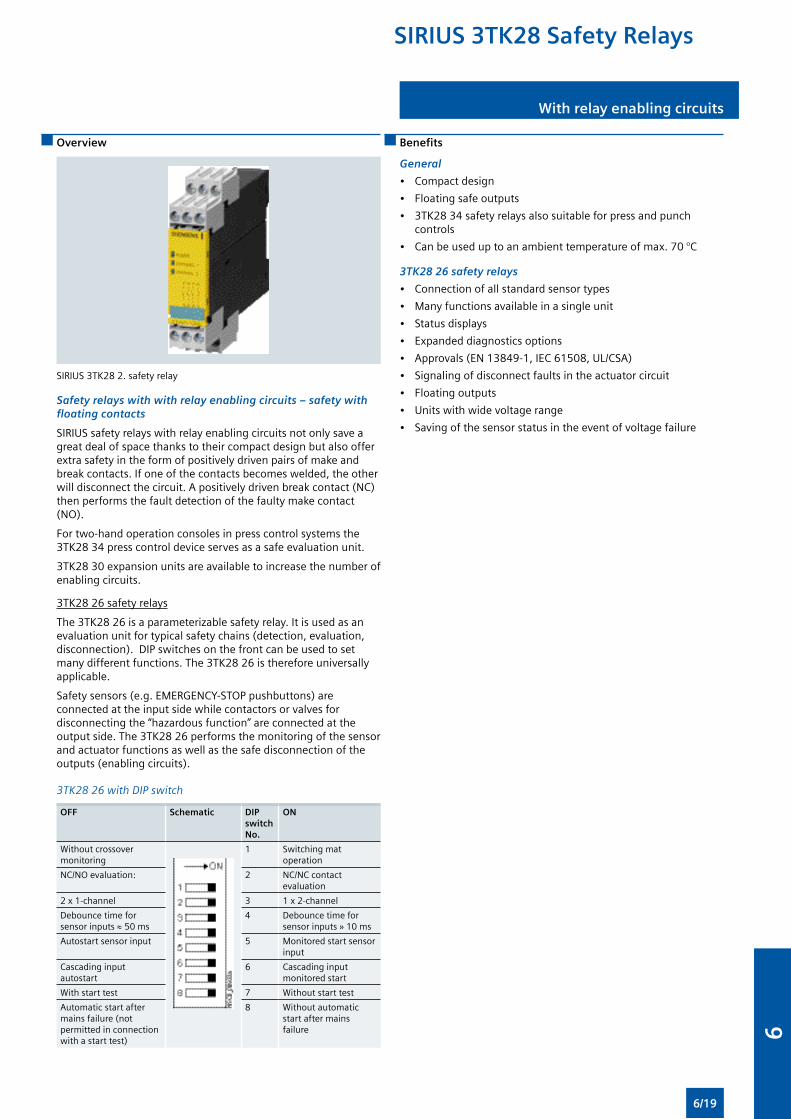
With relay enabling circuits
Overview
SIRIUS 3TK28 2. safety relay
Safety relays with with relay enabling circuits – safety with floating contacts
SIRIUS safety relays with relay enabling circuits not only save a great deal of space thanks to their compact design but also offer extra safety in the form of positively driven pairs of make and break contacts. If one of the contacts becomes welded, the other will disconnect the circuit. A positively driven break contact (NC) then performs the fault detection of the faulty make contact (NO).
For two-hand operation consoles in press control systems the 3TK28 34 press control device serves as a safe evaluation unit.
3TK28 30 expansion units are available to increase the number of enabling circuits.
3TK28 26 safety relays
The 3TK28 26 is a parameterizable safety relay. It is used as an evaluation unit for typical safety chains (detection, evaluation, disconnection). DIP switches on the front can be used to set many different functions. The 3TK28 26 is therefore universally applicable.
Safety sensors (e.g. EMERGENCY-STOP pushbuttons) are connected at the input side while contactors or valves for disconnecting the “hazardous function” are connected at the output side. The 3TK28 26 performs the monitoring of the sensor and actuator functions as well as the safe disconnection of the outputs (enabling circuits).
3TK28 26 with DIP switch
OFF Schematic DIP switch No.
ON
Without crossover monitoring
1 Switching mat operation
NC/NO evaluation: 2 NC/NC contact evaluation
2 x 1-channel 3 1 x 2-channel
Debounce time for sensor inputs ≈ 50 ms
4 Debounce time for sensor inputs » 10 ms
Autostart sensor input 5 Monitored start sensor input
Cascading input autostart
6 Cascading input monitored start
With start test 7 Without start test
Automatic start after mains failure (not permitted in connection with a start test)
8 Without automatic start after mains failure
Benefits
General
• Compact design
• Floating safe outputs
• 3TK28 34 safety relays also suitable for press and punch controls
• Can be used up to an ambient temperature of max. 70 °C
3TK28 26 safety relays
• Connection of all standard sensor types
• Many functions available in a single unit
• Status displays
• Expanded diagnostics options
• Approvals (EN 13849-1, IEC 61508, UL/CSA)
• Signaling of disconnect faults in the actuator circuit
• Floating outputs
• Units with wide voltage range
• Saving of the sensor status in the event of voltage failure
SIRIUS 3TK28 Safety Relays
6/19
6
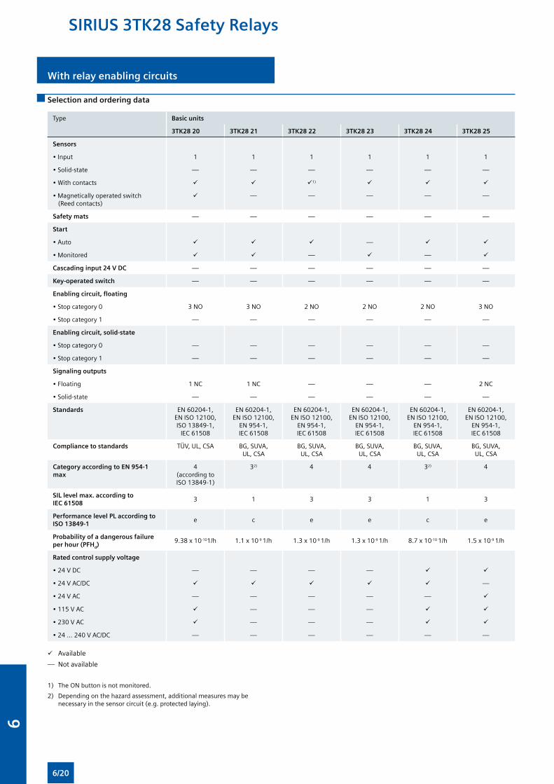
With relay enabling circuits
Selection and ordering data
Type Basic units
3TK28 20 3TK28 21 3TK28 22 3TK28 23 3TK28 24 3TK28 25
Sensors
• Input 1 1 1 1 1 1
• Solid-state — — — — — —
• With contacts 1)
• Magnetically operated switch (Reed contacts)
— — — — —
Safety mats — — — — — —
Start
• Auto —
• Monitored — —
Cascading input 24 V DC — — — — — —
Key-operated switch — — — — — —
Enabling circuit, floating
• Stop category 0 3 NO 3 NO 2 NO 2 NO 2 NO 3 NO
• Stop category 1 — — — — — —
Enabling circuit, solid-state
• Stop category 0 — — — — — —
• Stop category 1 — — — — — —
Signaling outputs
• Floating 1 NC 1 NC — — — 2 NC
• Solid-state — — — — — —
Standards EN 60204-1, EN ISO 12100, ISO 13849-1,
IEC 61508
EN 60204-1, EN ISO 12100,
EN 954-1, IEC 61508
EN 60204-1, EN ISO 12100,
EN 954-1, IEC 61508
EN 60204-1, EN ISO 12100,
EN 954-1, IEC 61508
EN 60204-1, EN ISO 12100,
EN 954-1, IEC 61508
EN 60204-1, EN ISO 12100,
EN 954-1, IEC 61508
Compliance to standards TÜV, UL, CSA BG, SUVA, UL, CSA
BG, SUVA, UL, CSA
BG, SUVA, UL, CSA
BG, SUVA, UL, CSA
BG, SUVA, UL, CSA
Category according to EN 954-1 max
4 (according to ISO 13849-1)
32) 4 4 32) 4
SIL level max. according to IEC 61508
3 1 3 3 1 3
Performance level PL according to ISO 13849-1
e c e e c e
Probability of a dangerous failure per hour (PFHd)
9.38 x 10-101/h 1.1 x 10⁻⁹ 1/h 1.3 x 10⁻⁹ 1/h 1.3 x 10⁻⁹ 1/h 8.7 x 10⁻¹⁰ 1/h 1.5 x 10⁻⁹ 1/h
Rated control supply voltage
• 24 V DC — — — —
• 24 V AC/DC —
• 24 V AC — — — — —
• 115 V AC — — —
• 230 V AC — — —
• 24 ... 240 V AC/DC — — — — — —
Available
— Not available
1) The ON button is not monitored.
2) Depending on the hazard assessment, additional measures may be necessary in the sensor circuit (e.g. protected laying).
SIRIUS 3TK28 Safety Relays
6/20
6
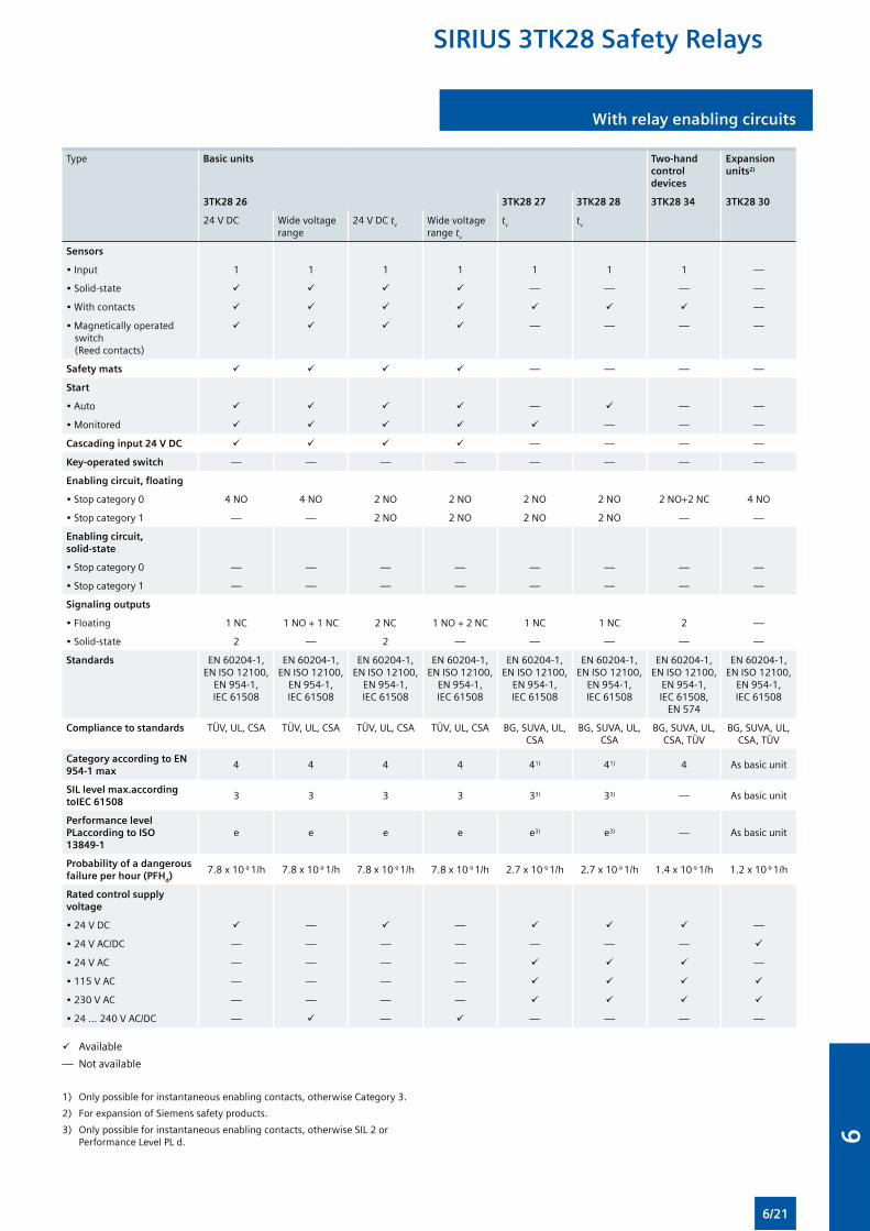
With relay enabling circuits
Type Basic units Two-hand control devices
Expansion units2)
3TK28 26 3TK28 27 3TK28 28 3TK28 34 3TK28 30
24 V DC Wide voltage range
24 V DC tv Wide voltage range tv
tv tv
Sensors
• Input 1 1 1 1 1 1 1 —
• Solid-state — — — —
• With contacts —
• Magnetically operated switch (Reed contacts)
— — — —
Safety mats — — — —
Start
• Auto — — —
• Monitored — — —
Cascading input 24 V DC — — — —
Key-operated switch — — — — — — — —
Enabling circuit, floating
• Stop category 0 4 NO 4 NO 2 NO 2 NO 2 NO 2 NO 2 NO+2 NC 4 NO
• Stop category 1 — — 2 NO 2 NO 2 NO 2 NO — —
Enabling circuit, solid-state
• Stop category 0 — — — — — — — —
• Stop category 1 — — — — — — — —
Signaling outputs
• Floating 1 NC 1 NO + 1 NC 2 NC 1 NO + 2 NC 1 NC 1 NC 2 —
• Solid-state 2 — 2 — — — — —
Standards EN 60204-1, EN ISO 12100,
EN 954-1, IEC 61508
EN 60204-1, EN ISO 12100,
EN 954-1, IEC 61508
EN 60204-1, EN ISO 12100,
EN 954-1, IEC 61508
EN 60204-1, EN ISO 12100,
EN 954-1, IEC 61508
EN 60204-1, EN ISO 12100,
EN 954-1, IEC 61508
EN 60204-1, EN ISO 12100,
EN 954-1, IEC 61508
EN 60204-1, EN ISO 12100,
EN 954-1, IEC 61508,
EN 574
EN 60204-1, EN ISO 12100,
EN 954-1, IEC 61508
Compliance to standards TÜV, UL, CSA TÜV, UL, CSA TÜV, UL, CSA TÜV, UL, CSA BG, SUVA, UL, CSA
BG, SUVA, UL, CSA
BG, SUVA, UL, CSA, TÜV
BG, SUVA, UL, CSA, TÜV
Category according to EN 954-1 max
4 4 4 4 41) 41) 4 As basic unit
SIL level max.according toIEC 61508
3 3 3 3 33) 33) — As basic unit
Performance level PLaccording to ISO 13849-1
e e e e e3) e3) — As basic unit
Probability of a dangerous failure per hour (PFHd)
7.8 x 10⁻⁹ 1/h 7.8 x 10⁻⁹ 1/h 7.8 x 10⁻⁹ 1/h 7.8 x 10⁻⁹ 1/h 2.7 x 10⁻⁹ 1/h 2.7 x 10⁻⁹ 1/h 1.4 x 10⁻⁹ 1/h 1.2 x 10⁻⁹ 1/h
Rated control supply voltage
• 24 V DC — — —
• 24 V AC/DC — — — — — — —
• 24 V AC — — — — —
• 115 V AC — — — —
• 230 V AC — — — —
• 24 ... 240 V AC/DC — — — — — —
Available
— Not available
1) Only possible for instantaneous enabling contacts, otherwise Category 3.
2) For expansion of Siemens safety products.
3) Only possible for instantaneous enabling contacts, otherwise SIL 2 or Performance Level PL d.
SIRIUS 3TK28 Safety Relays
6/21
6
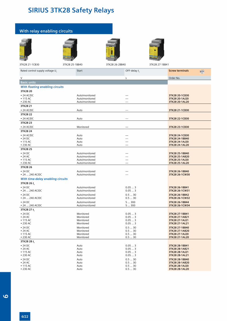
With relay enabling circuits
3TK28 21-1CB30 3TK28 25-1BB40 3TK28 26-2BB40 3TK28 27-1BB41
Rated control supply voltage Us Start OFF-delay tv Screw terminals
V s Order No.
Basic units
With floating enabling circuits3TK28 20
• 24 AC/DC• 115 AC• 230 AC
Auto/monitoredAuto/monitoredAuto/monitored
———
3TK28 20-1CB303TK28 20-1AJ203TK28 20-1AL20
3TK28 21
• 24 AC/DC Auto — 3TK28 21-1CB30
3TK28 22
• 24 AC/DC Auto — 3TK28 22-1CB30
3TK28 23
• 24 AC/DC Monitored — 3TK28 23-1CB30
3TK28 24
• 24 AC/DC• 24 DC• 115 AC• 230 AC
AutoAutoAutoAuto
————
3TK28 24-1CB303TK28 24-1BB403TK28 24-1AJ203TK28 24-1AL20
3TK28 25
• 24 DC• 24 AC• 115 AC• 230 AC
Auto/monitoredAuto/monitoredAuto/monitoredAuto/monitored
————
3TK28 25-1BB403TK28 25-1AB203TK28 25-1AJ203TK28 25-1AL20
3TK28 26
• 24 DC• 24 ... 240 AC/DC
Auto/monitoredAuto/monitored
——
3TK28 26-1BB403TK28 26-1CW30
With time-delay enabling circuits3TK28 26 tv
• 24 DC• 24 ... 240 AC/DC
Auto/monitoredAuto/monitored
0.05 ... 30.05 ... 3
3TK28 26-1BB413TK28 26-1CW31
• 24 DC• 24 ... 240 AC/DC
Auto/monitoredAuto/monitored
0.5 ... 300.5 ... 30
3TK28 26-1BB423TK28 26-1CW32
• 24 DC• 24 ... 240 AC/DC
Auto/monitoredAuto/monitored
5 ... 3005 ... 300
3TK28 26-1BB443TK28 26-1CW34
3TK28 27 tv
• 24 DC• 24 AC• 115 AC• 230 AC
MonitoredMonitoredMonitoredMonitored
0.05 ... 30.05 ... 30.05 ... 30.05 ... 3
3TK28 27-1BB413TK28 27-1AB213TK28 27-1AJ213TK28 27-1AL21
• 24 DC• 24 AC• 115 AC• 230 AC
MonitoredMonitoredMonitoredMonitored
0.5 ... 300.5 ... 300.5 ... 300.5 ... 30
3TK28 27-1BB403TK28 27-1AB203TK28 27-1AJ203TK28 27-1AL20
3TK28 28 tv
• 24 DC• 24 AC• 115 AC• 230 AC
AutoAutoAutoAuto
0.05 ... 30.05 ... 30.05 ... 30.05 ... 3
3TK28 28-1BB413TK28 28-1AB213TK28 28-1AJ213TK28 28-1AL21
• 24 DC• 24 AC• 115 AC• 230 AC
AutoAutoAutoAuto
0.5 ... 300.5 ... 300.5 ... 300.5 ... 30
3TK28 28-1BB403TK28 28-1AB203TK28 28-1AJ203TK28 28-1AL20
SIRIUS 3TK28 Safety Relays
6/22
6
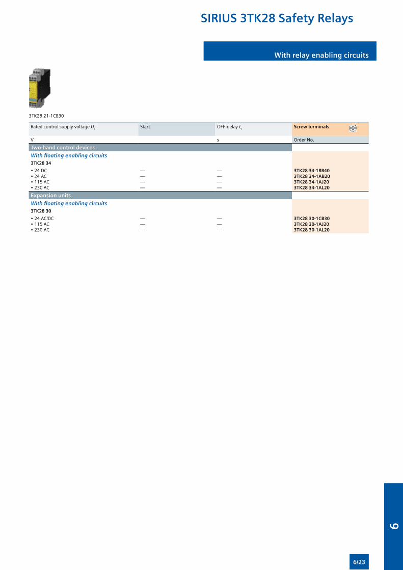
With relay enabling circuits
3TK28 21-1CB30
Rated control supply voltage Us Start OFF-delay tv Screw terminals
V s Order No.
Two-hand control devices
With floating enabling circuits3TK28 34
• 24 DC• 24 AC• 115 AC• 230 AC
————
————
3TK28 34-1BB403TK28 34-1AB203TK28 34-1AJ203TK28 34-1AL20
Expansion units
With floating enabling circuits3TK28 30
• 24 AC/DC• 115 AC• 230 AC
———
———
3TK28 30-1CB303TK28 30-1AJ203TK28 30-1AL20
SIRIUS 3TK28 Safety Relays
6/23
6
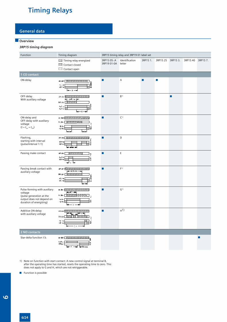
Overview
3RP15 timing diagram
Function Timing diagram 3RP15 timing relay and 3RP19 01 label set
Timing relay energized
Contact closed
Contact open
3RP15 05-.A3RP19 01-0A
Identification letter
3RP15 1. 3RP15 25 3RP15 3. 3RP15 40 3RP15 7.
1 CO contact
ON-delay n A n n
OFF-delay With auxiliary voltage
n B1) n
ON-delay and OFF-delay with auxiliary voltage (t = ton = toff)
n C1)
Flashing, starting with interval (pulse/interval 1:1)
n D
Passing make contact n E
Passing break contact with auxiliary voltage
n F1)
Pulse-forming with auxiliary voltage (pulse generation at the output does not depend on duration of energizing)
n G1)
Additive ON-delay with auxiliary voltage
n H1)
2 NO contacts
Star-delta function ϒ∆ n
General data
1) Note on function with start contact: A new control signal at terminal B, after the operating time has started, resets the operating time to zero. This does not apply to G and H, which are not retriggerable.
n Function is possible
Timing Relays
6/24
6
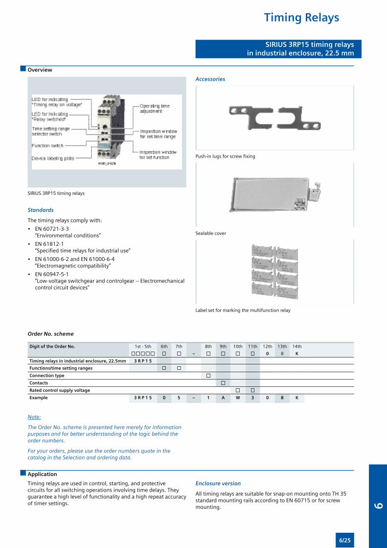
Overview
SIRIUS 3RP15 timing relaysin industrial enclosure, 22.5 mm
SIRIUS 3RP15 timing relays
Standards
The timing relays comply with:
• EN 60721-3-3 “Environmental conditions”
• EN 61812-1 “Specified time relays for industrial use”
• EN 61000-6-2 and EN 61000-6-4 “Electromagnetic compatibility”
• EN 60947-5-1 “Low-voltage switchgear and controlgear – Electromechanical control circuit devices”
Accessories
Push-in lugs for screw fixing
Sealable cover
Label set for marking the multifunction relay
Order No. scheme
Digit of the Order No. 1st - 5th 6th 7th 8th 9th 10th 11th 12th 13th 14th
– 0 8 K
Timing relays in industrial enclosure, 22.5mm 3 R P 1 5
Functions/time setting ranges
Connection type
Contacts
Rated control supply voltage
Example 3 R P 1 5 0 5 – 1 A W 3 0 8 K
Note:
The Order No. scheme is presented here merely for information purposes and for better understanding of the logic behind the order numbers.
For your orders, please use the order numbers quote in the catalog in the Selection and ordering data.
Application
Timing relays are used in control, starting, and protective circuits for all switching operations involving time delays. They guarantee a high level of functionality and a high repeat accuracy of timer settings.
Enclosure version
All timing relays are suitable for snap-on mounting onto TH 35 standard mounting rails according to EN 60715 or for screw mounting.
Timing Relays
6/25
6
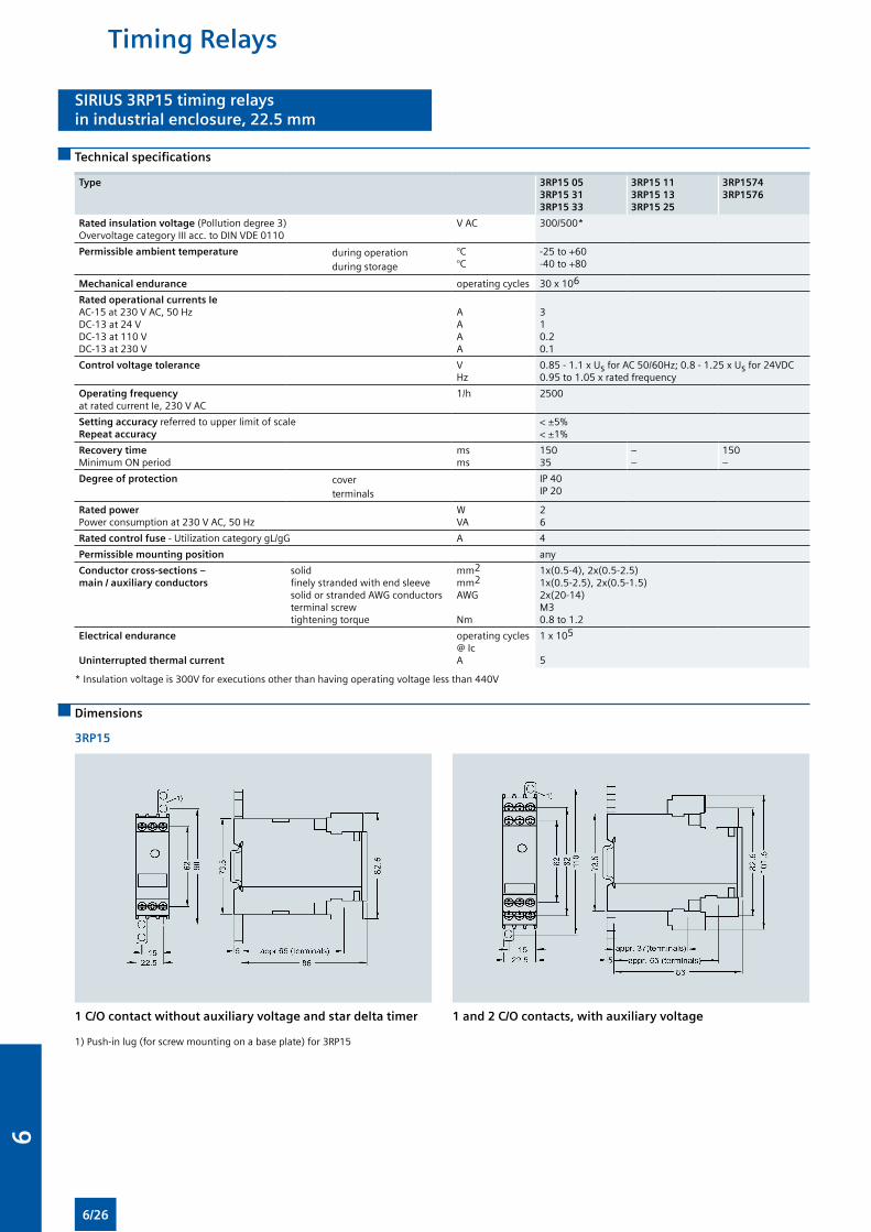
SIRIUS 3RP15 timing relaysin industrial enclosure, 22.5 mm
Technical specifications
Type 3RP15 05 3RP15 31 3RP15 33
3RP15 11 3RP15 13 3RP15 25
3RP15743RP1576
Rated insulation voltage (Pollution degree 3) Overvoltage category III acc. to DIN VDE 0110
V AC 300/500*
Permissible ambient temperature during operation during storage
°C°C
-25 to +60-40 to +80
Mechanical endurance operating cycles 30 x 106
Rated operational currents Ie AC-15 at 230 V AC, 50 HzDC-13 at 24 V DC-13 at 110 VDC-13 at 230 V
AA A A
310.20.1
Control voltage tolerance V Hz
0.85 - 1.1 x Us for AC 50/60Hz; 0.8 - 1.25 x Us for 24VDC 0.95 to 1.05 x rated frequency
Operating frequencyat rated current Ie, 230 V AC
1/h 2500
Setting accuracy referred to upper limit of scaleRepeat accuracy
< ±5%< ±1%
Recovery time Minimum ON period
ms ms
15035
––
150–
Degree of protection cover terminals
IP 40IP 20
Rated powerPower consumption at 230 V AC, 50 Hz
W VA
26
Rated control fuse - Utilization category gL/gG A 4
Permissible mounting position any
Conductor cross-sections – main / auxiliary conductors
solidfinely stranded with end sleevesolid or stranded AWG conductorsterminal screwtightening torque
mm2
mm2
AWG
Nm
1x(0.5-4), 2x(0.5-2.5)1x(0.5-2.5), 2x(0.5-1.5)2x(20-14)M30.8 to 1.2
Electrical endurance
Uninterrupted thermal current
operating cycles @ IcA
1 x 10⁵
5
* Insulation voltage is 300V for executions other than having operating voltage less than 440V
Dimensions
3RP15
1 C/O contact without auxiliary voltage and star delta timer
1) Push-in lug (for screw mounting on a base plate) for 3RP15
1 and 2 C/O contacts, with auxiliary voltage
Timing Relays
6/26
6
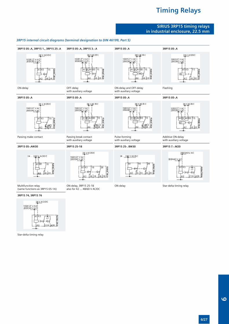
3RP15 internal circuit diagrams (terminal designation to DIN 46199, Part 5)
3RP15 05-.A, 3RP15 1., 3RP15 25-.A 3RP15 05-.A, 3RP15 3.-.A 3RP15 05-.A 3RP15 05-.A
ON-delay OFF-delay with auxiliary voltage
ON-delay and OFF-delay with auxiliary voltage
Flashing
3RP15 05-.A 3RP15 05-.A 3RP15 05-.A 3RP15 05-.A
Passing make contact Passing break contact with auxiliary voltage
Pulse-forming with auxiliary voltage
Additive ON-delay with auxiliary voltage
3RP15 05-.AW30 3RP15 25-1B 3RP15 25-. BW30 3RP15 7.-.M20
Multifunction relay (same functions as 3RP15 05-1A)
ON-delay, 3RP15 25-1Balso for 42 ... 48/60 V AC/DC
ON-delay Star-delta timing relay
3RP15 74, 3RP15 76
Star-delta timing relay
SIRIUS 3RP15 timing relaysin industrial enclosure, 22.5 mm
Timing Relays
6/27
6
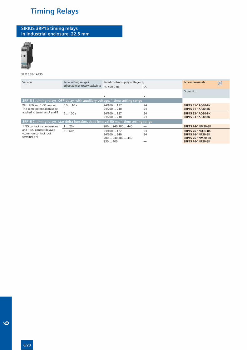
SIRIUS 3RP15 timing relaysin industrial enclosure, 22.5 mm
3RP15 33-1AP30
Version Time setting range t adjustable by rotary switch to
Rated control supply voltage Us Screw terminals
AC 50/60 Hz DC
Order No.
V V
3RP15 3. timing relays, OFF-delay, with auxiliary voltage, 1 time setting range With LED and 1 CO contact The same potential must be applied to terminals A and B
0.5 ... 10 s 24/100 ... 12724/200 ... 240
2424
3RP15 31-1AQ30-8K3RP15 31-1AP30-8K
5 ... 100 s 24/100 ... 12724/200 ... 240
2424
3RP15 33-1AQ30-8K3RP15 33-1AP30-8K
3RP15 7. timing relays, star-delta function, dead interval 50 ms, 1 time setting range1 NO contact instantaneous and 1 NO contact delayed (common contact root terminal 17)
1 ... 20 s 200 ... 240/380 ... 440 — 3RP15 74-1NM20-8K
3 ... 60 s 24/100 ... 12724/200 ... 240200 ... 240/380 ... 440230 ... 400
2424——
3RP15 76-1NQ30-8K3RP15 76-1NP30-8K3RP15 76-1NM20-8K3RP15 76-1NP20-8K
Timing Relays
6/28
6
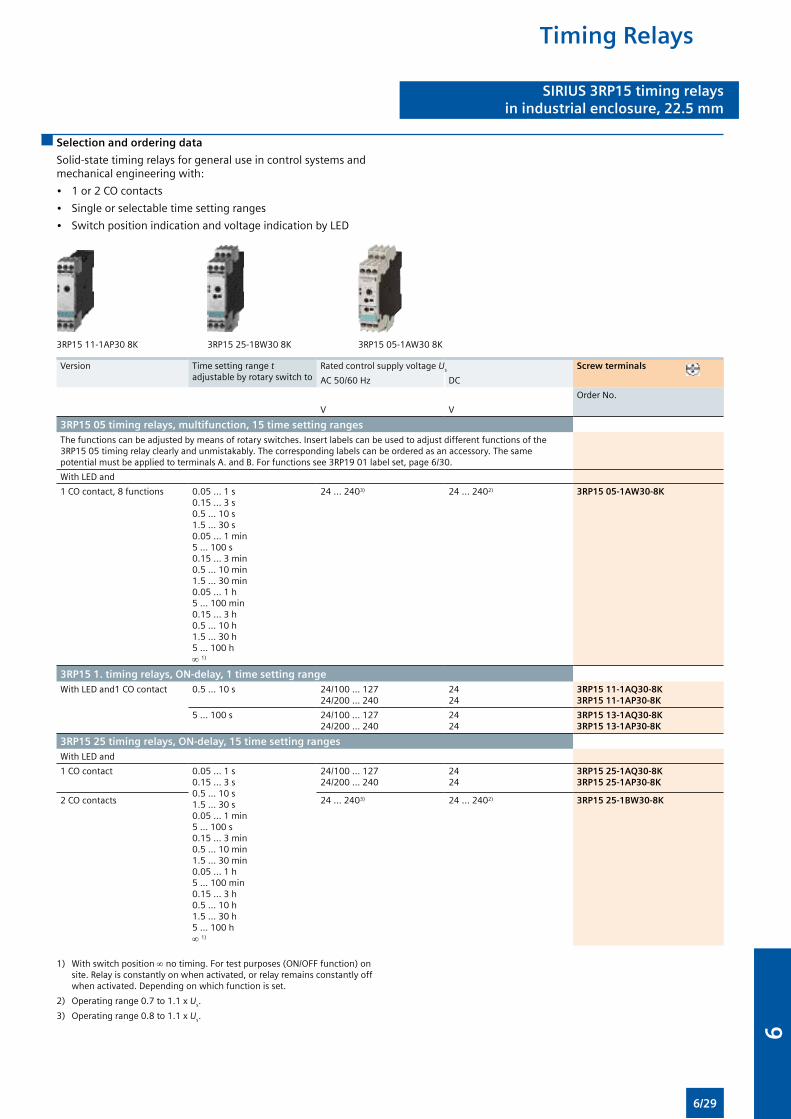
Selection and ordering data
Solid-state timing relays for general use in control systems and mechanical engineering with:
• 1 or 2 CO contacts
• Single or selectable time setting ranges
• Switch position indication and voltage indication by LED
SIRIUS 3RP15 timing relaysin industrial enclosure, 22.5 mm
3RP15 11-1AP30 8K 3RP15 25-1BW30 8K 3RP15 05-1AW30 8K
Version Time setting range t adjustable by rotary switch to
Rated control supply voltage Us Screw terminals
AC 50/60 Hz DC
Order No.
V V
3RP15 05 timing relays, multifunction, 15 time setting rangesThe functions can be adjusted by means of rotary switches. Insert labels can be used to adjust different functions of the 3RP15 05 timing relay clearly and unmistakably. The corresponding labels can be ordered as an accessory. The same potential must be applied to terminals A. and B. For functions see 3RP19 01 label set, page 6/30.
With LED and
1 CO contact, 8 functions 0.05 ... 1 s 0.15 ... 3 s 0.5 ... 10 s 1.5 ... 30 s 0.05 ... 1 min5 ... 100 s0.15 ... 3 min 0.5 ... 10 min 1.5 ... 30 min 0.05 ... 1 h 5 ... 100 min0.15 ... 3 h 0.5 ... 10 h 1.5 ... 30 h 5 ... 100 h ∞ 1)
24 ... 2403) 24 ... 2402) 3RP15 05-1AW30-8K
3RP15 1. timing relays, ON-delay, 1 time setting rangeWith LED and1 CO contact 0.5 ... 10 s 24/100 ... 127
24/200 ... 2402424
3RP15 11-1AQ30-8K3RP15 11-1AP30-8K
5 ... 100 s 24/100 ... 12724/200 ... 240
2424
3RP15 13-1AQ30-8K3RP15 13-1AP30-8K
3RP15 25 timing relays, ON-delay, 15 time setting rangesWith LED and
1 CO contact 0.05 ... 1 s 0.15 ... 3 s 0.5 ... 10 s 1.5 ... 30 s 0.05 ... 1 min5 ... 100 s0.15 ... 3 min 0.5 ... 10 min 1.5 ... 30 min 0.05 ... 1 h 5 ... 100 min0.15 ... 3 h 0.5 ... 10 h 1.5 ... 30 h 5 ... 100 h ∞ 1)
24/100 ... 12724/200 ... 240
2424
3RP15 25-1AQ30-8K3RP15 25-1AP30-8K
2 CO contacts 24 ... 2403) 24 ... 2402) 3RP15 25-1BW30-8K
1) With switch position ∞ no timing. For test purposes (ON/OFF function) on site. Relay is constantly on when activated, or relay remains constantly off when activated. Depending on which function is set.
2) Operating range 0.7 to 1.1 x Us.
3) Operating range 0.8 to 1.1 x Us.
Timing Relays
6/29
6
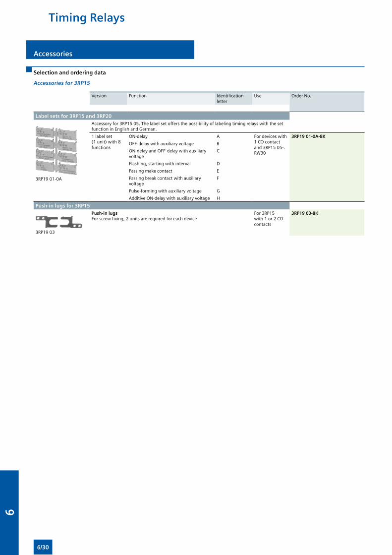
Selection and ordering data
Accessories for 3RP15
Version Function Identification letter
Use Order No.
Label sets for 3RP15 and 3RP20
3RP19 01-0A
Accessory for 3RP15 05. The label set offers the possibility of labeling timing relays with the set function in English and German.
1 label set (1 unit) with 8 functions
ON-delay A For devices with 1 CO contact and 3RP15 05-.RW30
3RP19 01-0A-8K
OFF-delay with auxiliary voltage B
ON-delay and OFF-delay with auxiliary voltage
C
Flashing, starting with interval D
Passing make contact E
Passing break contact with auxiliary voltage
F
Pulse-forming with auxiliary voltage G
Additive ON-delay with auxiliary voltage H
Push-in lugs for 3RP15
3RP19 03
Push-in lugs For screw fixing, 2 units are required for each device
For 3RP15 with 1 or 2 CO contacts
3RP19 03-8K
Accessories
Timing Relays
6/30
6
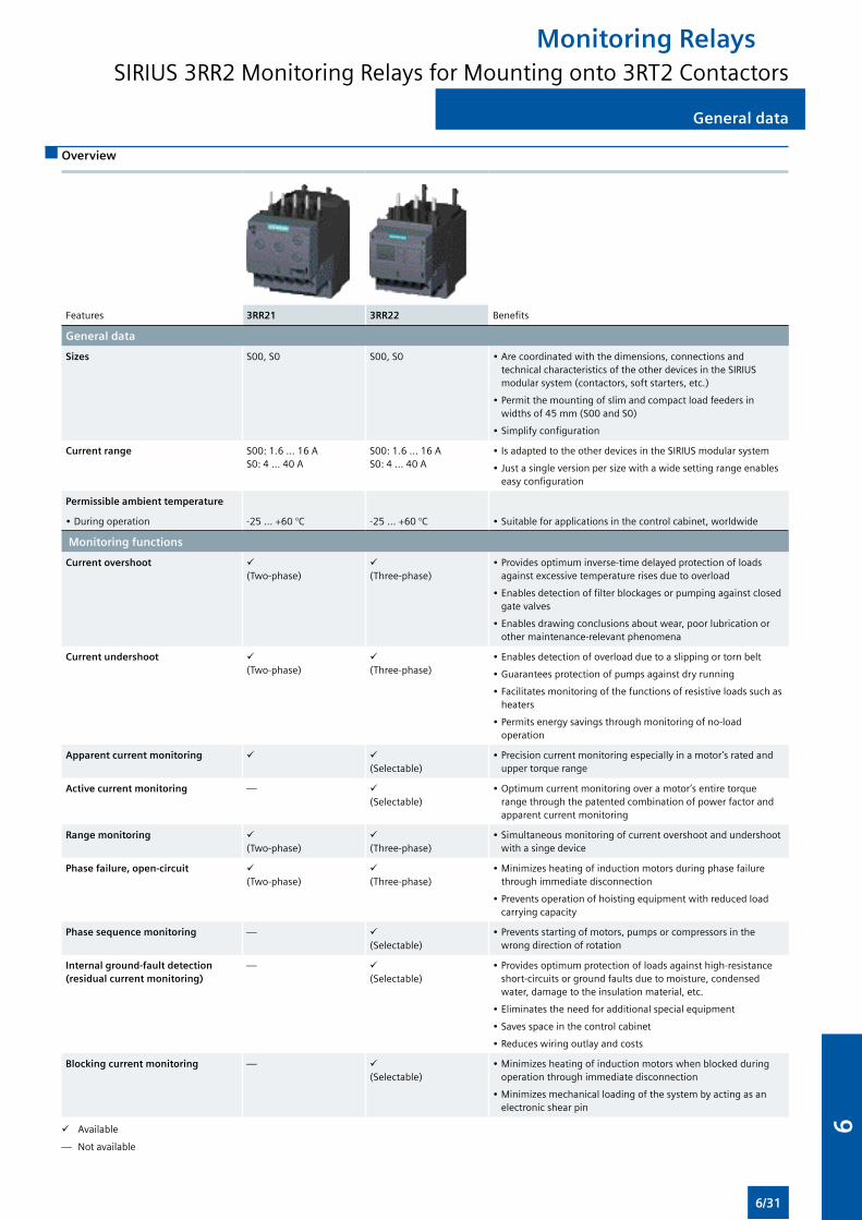
General data
Overview
Features 3RR21 3RR22 Benefits
General data
Sizes S00, S0 S00, S0 • Are coordinated with the dimensions, connections and technical characteristics of the other devices in the SIRIUS modular system (contactors, soft starters, etc.)
• Permit the mounting of slim and compact load feeders in widths of 45 mm (S00 and S0)
• Simplify configuration
Current range S00: 1.6 ... 16 A S0: 4 ... 40 A
S00: 1.6 ... 16 A S0: 4 ... 40 A
• Is adapted to the other devices in the SIRIUS modular system
• Just a single version per size with a wide setting range enables easy configuration
Permissible ambient temperature
• During operation -25 ... +60 °C -25 ... +60 °C • Suitable for applications in the control cabinet, worldwide
Monitoring functions
Current overshoot (Two-phase)
(Three-phase)
• Provides optimum inverse-time delayed protection of loads against excessive temperature rises due to overload
• Enables detection of filter blockages or pumping against closed gate valves
• Enables drawing conclusions about wear, poor lubrication or other maintenance-relevant phenomena
Current undershoot (Two-phase)
(Three-phase)
• Enables detection of overload due to a slipping or torn belt
• Guarantees protection of pumps against dry running
• Facilitates monitoring of the functions of resistive loads such as heaters
• Permits energy savings through monitoring of no-load operation
Apparent current monitoring (Selectable)
• Precision current monitoring especially in a motor’s rated and upper torque range
Active current monitoring — (Selectable)
• Optimum current monitoring over a motor’s entire torque range through the patented combination of power factor and apparent current monitoring
Range monitoring (Two-phase)
(Three-phase)
• Simultaneous monitoring of current overshoot and undershoot with a singe device
Phase failure, open-circuit (Two-phase)
(Three-phase)
• Minimizes heating of induction motors during phase failure through immediate disconnection
• Prevents operation of hoisting equipment with reduced load carrying capacity
Phase sequence monitoring — (Selectable)
• Prevents starting of motors, pumps or compressors in the wrong direction of rotation
Internal ground-fault detection (residual current monitoring)
— (Selectable)
• Provides optimum protection of loads against high-resistance short-circuits or ground faults due to moisture, condensed water, damage to the insulation material, etc.
• Eliminates the need for additional special equipment
• Saves space in the control cabinet
• Reduces wiring outlay and costs
Blocking current monitoring — (Selectable)
• Minimizes heating of induction motors when blocked during operation through immediate disconnection
• Minimizes mechanical loading of the system by acting as an electronic shear pin
Available
— Not available
Monitoring RelaysSIRIUS 3RR2 Monitoring Relays for Mounting onto 3RT2 Contactors
6/31
6
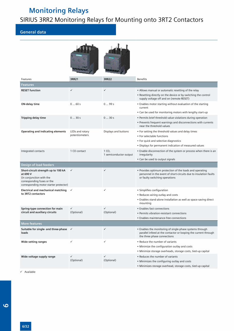
General data
Features 3RR21 3RR22 Benefits
Features
RESET function • Allows manual or automatic resetting of the relay
• Resetting directly on the device or by switching the control supply voltage off and on (remote RESET)
ON-delay time 0 ... 60 s 0 ... 99 s • Enables motor starting without evaluation of the starting current
• Can be used for monitoring motors with lengthy start-up
Tripping delay time 0 ... 30 s 0 ... 30 s • Permits brief threshold value violations during operation
• Prevents frequent warnings and disconnections with currents near the threshold values
Operating and indicating elements LEDs and rotary potentiometers
Displays and buttons • For setting the threshold values and delay times
• For selectable functions
• For quick and selective diagnostics
• Displays for permanent indication of measured values
Integrated contacts 1 CO contact 1 CO, 1 semiconductor output
• Enable disconnection of the system or process when there is an irregularity
• Can be used to output signals
Design of load feeders
Short-circuit strength up to 100 kA at 690 V (in conjunction with the corresponding fuses or the corresponding motor starter protector)
• Provides optimum protection of the loads and operating personnel in the event of short-circuits due to insulation faults or faulty switching operations
Electrical and mechanical matching to 3RT2 contactors
• Simplifies configuration
• Reduces wiring outlay and costs
• Enables stand-alone installation as well as space-saving direct mounting
Spring-type connection for main circuit and auxiliary circuits
(Optional)
(Optional)
• Enables fast connections
• Permits vibration-resistant connections
• Enables maintenance-free connections
More features
Suitable for single- and three-phase loads
• Enables the monitoring of single-phase systems through parallel infeed at the contactor or looping the current through the three phase connections
Wide setting ranges • Reduce the number of variants
• Minimize the configuration outlay and costs
• Minimize storage overheads, storage costs, tied-up capital
Wide voltage supply range (Optional)
(Optional)
• Reduces the number of variants
• Minimizes the configuring outlay and costs
• Minimizes storage overhead, storage costs, tied-up capital
Available
Monitoring RelaysSIRIUS 3RR2 Monitoring Relays for Mounting onto 3RT2 Contactors
6/32
6
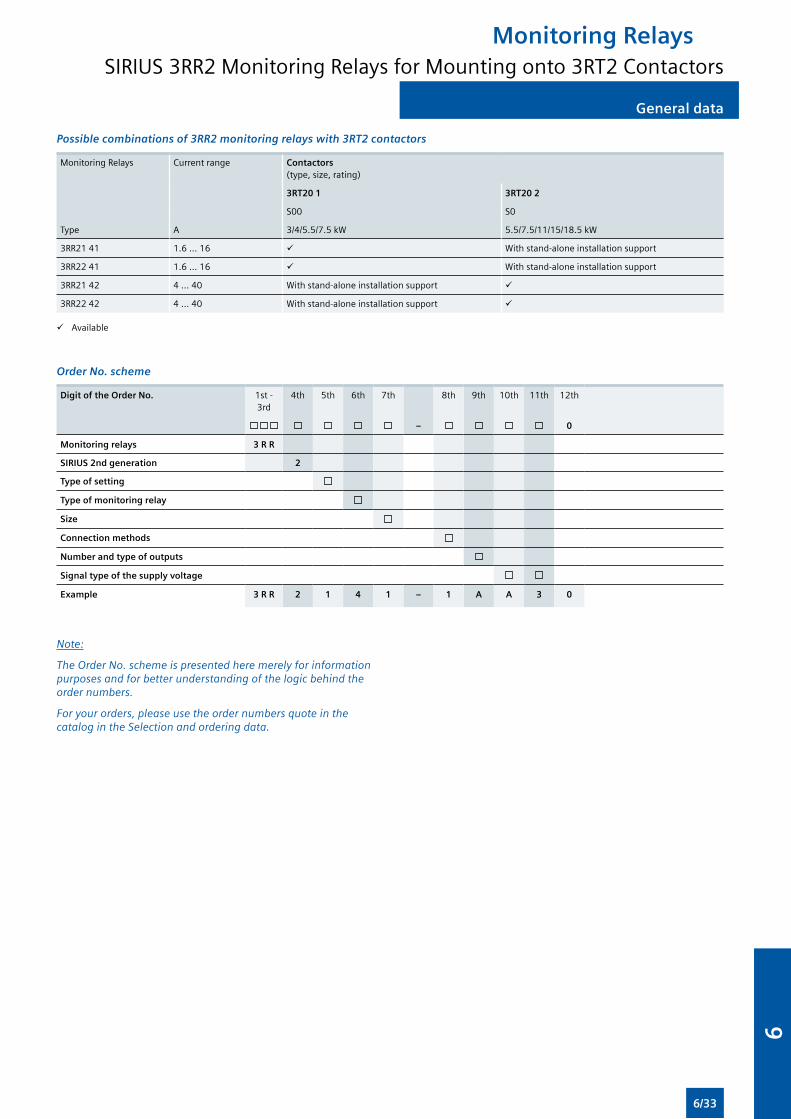
General data
Possible combinations of 3RR2 monitoring relays with 3RT2 contactors
Monitoring Relays Current range Contactors (type, size, rating)
3RT20 1 3RT20 2
S00 S0
Type A 3/4/5.5/7.5 kW 5.5/7.5/11/15/18.5 kW
3RR21 41 1.6 ... 16 With stand-alone installation support
3RR22 41 1.6 ... 16 With stand-alone installation support
3RR21 42 4 ... 40 With stand-alone installation support
3RR22 42 4 ... 40 With stand-alone installation support
Available
Order No. scheme
Digit of the Order No. 1st - 3rd
4th 5th 6th 7th 8th 9th 10th 11th 12th
– 0
Monitoring relays 3 R R
SIRIUS 2nd generation 2
Type of setting
Type of monitoring relay
Size
Connection methods
Number and type of outputs
Signal type of the supply voltage
Example 3 R R 2 1 4 1 – 1 A A 3 0
Note:
The Order No. scheme is presented here merely for information purposes and for better understanding of the logic behind the order numbers.
For your orders, please use the order numbers quote in the catalog in the Selection and ordering data.
Monitoring RelaysSIRIUS 3RR2 Monitoring Relays for Mounting onto 3RT2 Contactors
6/33
6
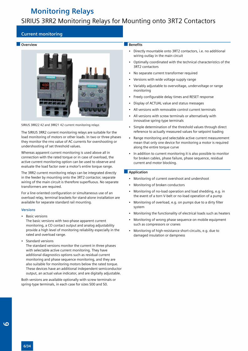
Current monitoring
Overview
SIRIUS 3RR22 42 and 3RR21 42 current monitoring relays
The SIRIUS 3RR2 current monitoring relays are suitable for the load monitoring of motors or other loads. In two or three phases they monitor the rms value of AC currents for overshooting or undershooting of set threshold values.
Whereas apparent current monitoring is used above all in connection with the rated torque or in case of overload, the active current monitoring option can be used to observe and evaluate the load factor over a motor’s entire torque range.
The 3RR2 current monitoring relays can be integrated directly in the feeder by mounting onto the 3RT2 contactor; separate wiring of the main circuit is therefore superfluous. No separate transformers are required.
For a line-oriented configuration or simultaneous use of an overload relay, terminal brackets for stand-alone installation are available for separate standard rail mounting.
Versions
• Basic versions The basic versions with two-phase apparent current monitoring, a CO contact output and analog adjustability provide a high level of monitoring reliability especially in the rated and overload range.
• Standard versions The standard versions monitor the current in three phases with selectable active current monitoring. They have additional diagnostics options such as residual current monitoring and phase sequence monitoring, and they are also suitable for monitoring motors below the rated torque. These devices have an additional independent semiconductor output, an actual value indicator, and are digitally adjustable.
Both versions are available optionally with screw terminals or spring-type terminals, in each case for sizes S00 and S0.
Benefits
• Directly mountable onto 3RT2 contactors, i.e. no additional wiring outlay in the main circuit
• Optimally coordinated with the technical characteristics of the 3RT2 contactors
• No separate current transformer required
• Versions with wide voltage supply range
• Variably adjustable to overvoltage, undervoltage or range monitoring
• Freely configurable delay times and RESET response
• Display of ACTUAL value and status messages
• All versions with removable control current terminals
• All versions with screw terminals or alternatively with innovative spring-type terminals
• Simple determination of the threshold values through direct reference to actually measured values for setpoint loading
• Range monitoring and selectable active current measurement mean that only one device for monitoring a motor is required along the entire torque curve
• In addition to current monitoring it is also possible to monitor for broken cables, phase failure, phase sequence, residual current and motor blocking.
Application
• Monitoring of current overshoot and undershoot
• Monitoring of broken conductors
• Monitoring of no-load operation and load shedding, e.g. in the event of a torn V-belt or no-load operation of a pump
• Monitoring of overload, e.g. on pumps due to a dirty filter system
• Monitoring the functionality of electrical loads such as heaters
• Monitoring of wrong phase sequence on mobile equipment such as compressors or cranes
• Monitoring of high-resistance short-circuits, e.g. due to damaged insulation or dampness
Monitoring RelaysSIRIUS 3RR2 Monitoring Relays for Mounting onto 3RT2 Contactors
6/34
6
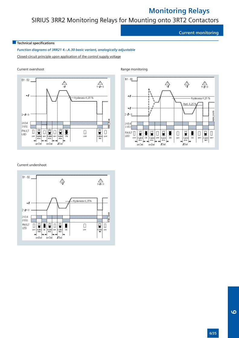
Current monitoring
Technical specifications
Function diagrams of 3RR21 4.-.A.30 basic variant, analogically adjustable
Closed-circuit principle upon application of the control supply voltage
Current overshoot Range monitoring
Current undershoot
Monitoring RelaysSIRIUS 3RR2 Monitoring Relays for Mounting onto 3RT2 Contactors
6/35
6

Current monitoring
Function diagrams of 3RR22 4.-.F.30 standard version, digitally adjustable
With the closed-circuit principle selected upon application of the control supply voltage
Current overshoot
Current undershoot with residual current monitoring
Range monitoring
Phase sequence monitoring
Monitoring RelaysSIRIUS 3RR2 Monitoring Relays for Mounting onto 3RT2 Contactors
6/36
6
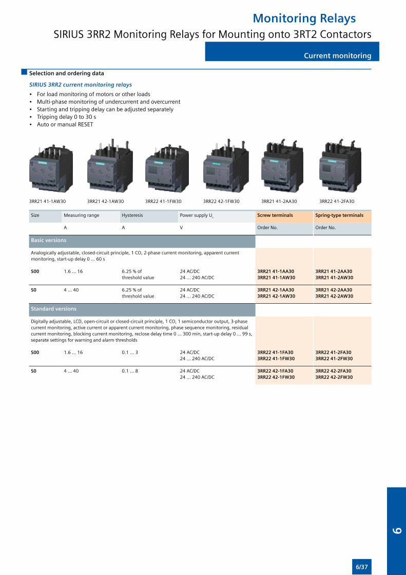
Current monitoring
Selection and ordering data
SIRIUS 3RR2 current monitoring relays
• For load monitoring of motors or other loads• Multi-phase monitoring of undercurrent and overcurrent• Starting and tripping delay can be adjusted separately• Tripping delay 0 to 30 s• Auto or manual RESET
3RR21 41-1AW30 3RR21 42-1AW30 3RR22 41-1FW30 3RR22 42-1FW30 3RR21 41-2AA30 3RR22 41-2FA30
Size Measuring range Hysteresis Power supply Us Screw terminals Spring-type terminals
A A V Order No. Order No.
Basic versions
Analogically adjustable, closed-circuit principle, 1 CO, 2-phase current monitoring, apparent current monitoring, start-up delay 0 ... 60 s
S00 1.6 ... 16 6.25 % of threshold value
24 AC/DC 24 ... 240 AC/DC
3RR21 41-1AA30 3RR21 41-1AW30
3RR21 41-2AA30 3RR21 41-2AW30
S0 4 ... 40 6.25 % of threshold value
24 AC/DC 24 ... 240 AC/DC
3RR21 42-1AA30 3RR21 42-1AW30
3RR21 42-2AA30 3RR21 42-2AW30
Standard versions
Digitally adjustable, LCD, open-circuit or closed-circuit principle, 1 CO, 1 semiconductor output, 3-phase current monitoring, active current or apparent current monitoring, phase sequence monitoring, residual current monitoring, blocking current monitoring, reclose delay time 0 ... 300 min, start-up delay 0 ... 99 s, separate settings for warning and alarm thresholds
S00 1.6 ... 16 0.1 ... 3 24 AC/DC24 ... 240 AC/DC
3RR22 41-1FA303RR22 41-1FW30
3RR22 41-2FA303RR22 41-2FW30
S0 4 ... 40 0.1 ... 8 24 AC/DC24 ... 240 AC/DC
3RR22 42-1FA303RR22 42-1FW30
3RR22 42-2FA303RR22 42-2FW30
Monitoring RelaysSIRIUS 3RR2 Monitoring Relays for Mounting onto 3RT2 Contactors
6/37
6
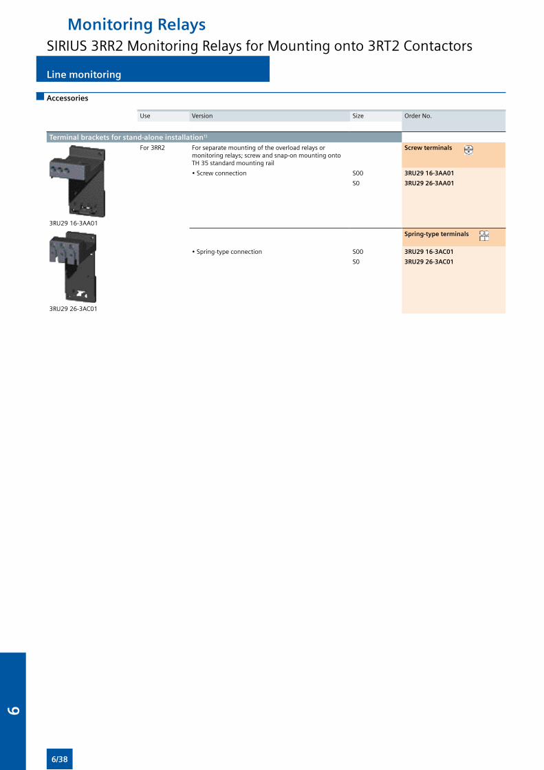
Accessories
Use Version Size Order No.
Terminal brackets for stand-alone installation1)
3RU29 16-3AA01
For 3RR2 For separate mounting of the overload relays or monitoring relays; screw and snap-on mounting onto TH 35 standard mounting rail
Screw terminals
• Screw connection S00 3RU29 16-3AA01
S0 3RU29 26-3AA01
3RU29 26-3AC01
Spring-type terminals
• Spring-type connection S00 3RU29 16-3AC01
S0 3RU29 26-3AC01
Line monitoring
Monitoring RelaysSIRIUS 3RR2 Monitoring Relays for Mounting onto 3RT2 Contactors
6/38
6
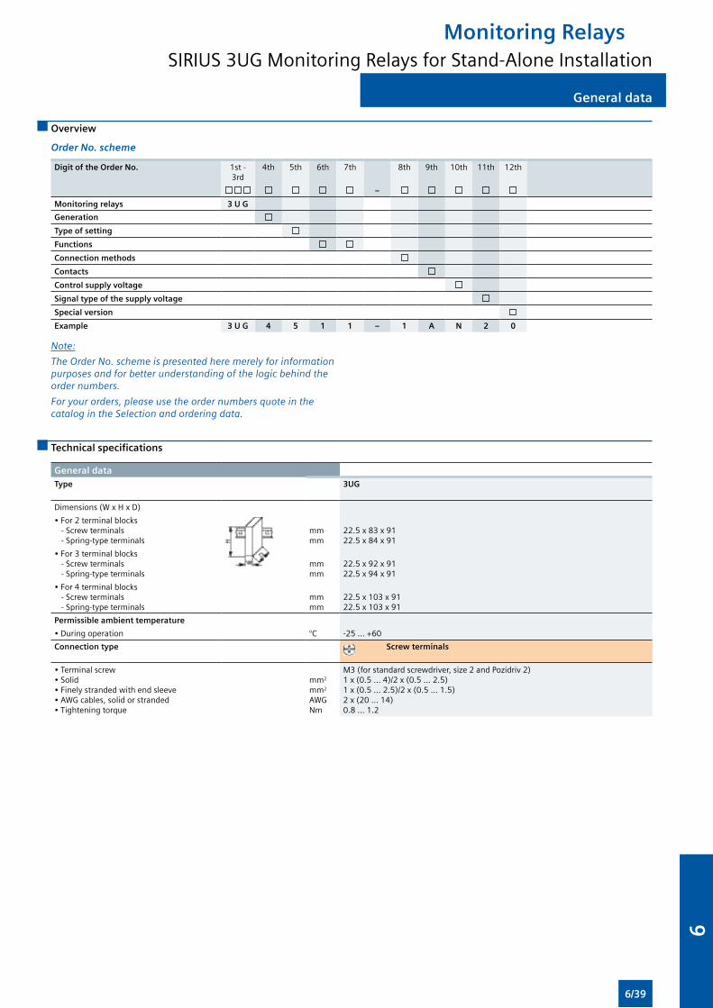
Overview
Order No. scheme
Digit of the Order No. 1st - 3rd
4th 5th 6th 7th 8th 9th 10th 11th 12th
–
Monitoring relays 3 U G
Generation
Type of setting
Functions
Connection methods
Contacts
Control supply voltage
Signal type of the supply voltage
Special version
Example 3 U G 4 5 1 1 – 1 A N 2 0
General data
Note:
The Order No. scheme is presented here merely for information purposes and for better understanding of the logic behind the order numbers.
For your orders, please use the order numbers quote in the catalog in the Selection and ordering data.
Technical specifications
General dataType 3UG
Dimensions (W x H x D)
• For 2 terminal blocks - Screw terminals - Spring-type terminals
mmmm
22.5 x 83 x 9122.5 x 84 x 91
• For 3 terminal blocks - Screw terminals - Spring-type terminals
mmmm
22.5 x 92 x 9122.5 x 94 x 91
• For 4 terminal blocks - Screw terminals - Spring-type terminals
mmmm
22.5 x 103 x 9122.5 x 103 x 91
Permissible ambient temperature
• During operation °C -25 ... +60
Connection type Screw terminals
• Terminal screw• Solid• Finely stranded with end sleeve• AWG cables, solid or stranded• Tightening torque
mm2
mm2
AWGNm
M3 (for standard screwdriver, size 2 and Pozidriv 2)1 x (0.5 ... 4)/2 x (0.5 ... 2.5)1 x (0.5 ... 2.5)/2 x (0.5 ... 1.5)2 x (20 ... 14)0.8 … 1.2
Monitoring RelaysSIRIUS 3UG Monitoring Relays for Stand-Alone Installation
6/39
6
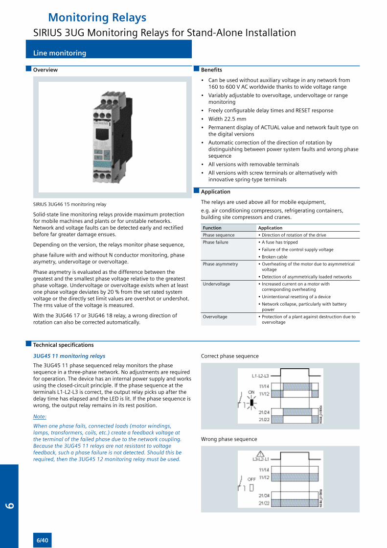
Line monitoring
Overview
SIRIUS 3UG46 15 monitoring relay
Solid-state line monitoring relays provide maximum protection for mobile machines and plants or for unstable networks. Network and voltage faults can be detected early and rectified before far greater damage ensues.
Depending on the version, the relays monitor phase sequence,
phase failure with and without N conductor monitoring, phase asymetry, undervoltage or overvoltage.
Phase asymetry is evaluated as the difference between the greatest and the smallest phase voltage relative to the greatest phase voltage. Undervoltage or overvoltage exists when at least one phase voltage deviates by 20 % from the set rated system voltage or the directly set limit values are overshot or undershot. The rms value of the voltage is measured.
With the 3UG46 17 or 3UG46 18 relay, a wrong direction of rotation can also be corrected automatically.
Benefits
• Can be used without auxiliary voltage in any network from 160 to 600 V AC worldwide thanks to wide voltage range
• Variably adjustable to overvoltage, undervoltage or range monitoring
• Freely configurable delay times and RESET response
• Width 22.5 mm
• Permanent display of ACTUAL value and network fault type on the digital versions
• Automatic correction of the direction of rotation by distinguishing between power system faults and wrong phase sequence
• All versions with removable terminals
• All versions with screw terminals or alternatively with innovative spring-type terminals
Application
The relays are used above all for mobile equipment,
e.g. air conditioning compressors, refrigerating containers, building site compressors and cranes.
Function Application
Phase sequence • Direction of rotation of the drive
Phase failure • A fuse has tripped
• Failure of the control supply voltage
• Broken cable
Phase asymmetry • Overheating of the motor due to asymmetrical voltage
• Detection of asymmetrically loaded networks
Undervoltage • Increased current on a motor with corresponding overheating
• Unintentional resetting of a device
• Network collapse, particularly with battery power
Overvoltage • Protection of a plant against destruction due to overvoltage
Technical specifications
3UG45 11 monitoring relays
The 3UG45 11 phase sequenced relay monitors the phase sequence in a three-phase network. No adjustments are required for operation. The device has an internal power supply and works using the closed-circuit principle. If the phase sequence at the terminals L1-L2-L3 is correct, the output relay picks up after the delay time has elapsed and the LED is lit. If the phase sequence is wrong, the output relay remains in its rest position.
Note:
When one phase fails, connected loads (motor windings, lamps, transformers, coils, etc.) create a feedback voltage at the terminal of the failed phase due to the network coupling. Because the 3UG45 11 relays are not resistant to voltage feedback, such a phase failure is not detected. Should this be required, then the 3UG45 12 monitoring relay must be used.
Correct phase sequence
Wrong phase sequence
Monitoring RelaysSIRIUS 3UG Monitoring Relays for Stand-Alone Installation
6/40
6
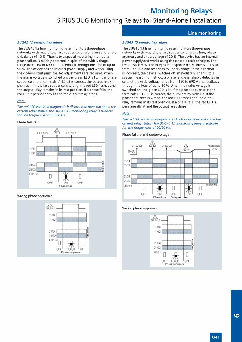
Line monitoring
3UG45 12 monitoring relays
The 3UG45 12 line monitoring relay monitors three-phase networks with regard to phase sequence, phase failure and phase unbalance of 10 %. Thanks to a special measuring method, a phase failure is reliably detected in spite of the wide voltage range from 160 to 690 V and feedback through the load of up to 90 %. The device has an internal power supply and works using the closed-circuit principle. No adjustments are required. When the mains voltage is switched on, the green LED is lit. If the phase sequence at the terminals L1-L2-L3 is correct, the output relay picks up. If the phase sequence is wrong, the red LED flashes and the output relay remains in its rest position. If a phase fails, the red LED is permanently lit and the output relay drops.
Note:
The red LED is a fault diagnostic indicator and does not show the current relay status. The 3UG45 12 monitoring relay is suitable for line frequencies of 50/60 Hz.
Phase failure
Wrong phase sequence
3UG45 13 monitoring relays
The 3UG45 13 line monitoring relay monitors three-phase networks with regard to phase sequence, phase failure, phase asymetry and undervoltage of 20 %. The device has an internal power supply and works using the closed-circuit principle. The hysteresis is 5 %. The integrated response delay time is adjustable from 0 to 20 s and responds to undervoltage. If the direction is incorrect, the device switches off immediately. Thanks to a special measuring method, a phase failure is reliably detected in spite of the wide voltage range from 160 to 690 V and feedback through the load of up to 80 %. When the mains voltage is switched on, the green LED is lit. If the phase sequence at the terminals L1-L2-L3 is correct, the output relay picks up. If the phase sequence is wrong, the red LED flashes and the output relay remains in its rest position. If a phase fails, the red LED is permanently lit and the output relay drops.
Note:
The red LED is a fault diagnostic indicator and does not show the current relay status. The 3UG45 13 monitoring relay is suitable for line frequencies of 50/60 Hz.
Phase failure and undervoltage
Wrong phase sequence
Monitoring RelaysSIRIUS 3UG Monitoring Relays for Stand-Alone Installation
6/41
6
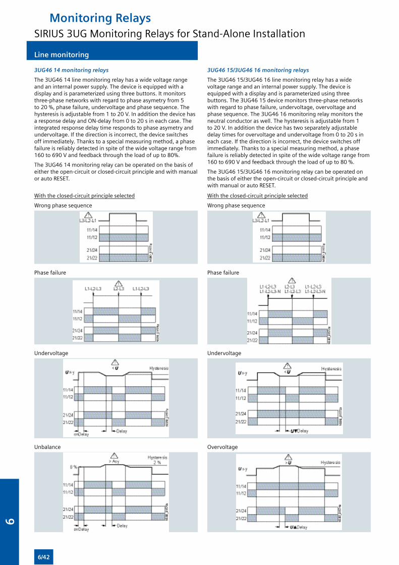
Line monitoring
3UG46 14 monitoring relays
The 3UG46 14 line monitoring relay has a wide voltage range and an internal power supply. The device is equipped with a display and is parameterized using three buttons. It monitors three-phase networks with regard to phase asymetry from 5 to 20 %, phase failure, undervoltage and phase sequence. The hysteresis is adjustable from 1 to 20 V. In addition the device has a response delay and ON-delay from 0 to 20 s in each case. The integrated response delay time responds to phase asymetry and undervoltage. If the direction is incorrect, the device switches off immediately. Thanks to a special measuring method, a phase failure is reliably detected in spite of the wide voltage range from 160 to 690 V and feedback through the load of up to 80%.
The 3UG46 14 monitoring relay can be operated on the basis of either the open-circuit or closed-circuit principle and with manual or auto RESET.
3UG46 15/3UG46 16 monitoring relays
The 3UG46 15/3UG46 16 line monitoring relay has a wide voltage range and an internal power supply. The device is equipped with a display and is parameterized using three buttons. The 3UG46 15 device monitors three-phase networks with regard to phase failure, undervoltage, overvoltage and phase sequence. The 3UG46 16 monitoring relay monitors the neutral conductor as well. The hysteresis is adjustable from 1 to 20 V. In addition the device has two separately adjustable delay times for overvoltage and undervoltage from 0 to 20 s in each case. If the direction is incorrect, the device switches off immediately. Thanks to a special measuring method, a phase failure is reliably detected in spite of the wide voltage range from 160 to 690 V and feedback through the load of up to 80 %.
The 3UG46 15/3UG46 16 monitoring relay can be operated on the basis of either the open-circuit or closed-circuit principle and with manual or auto RESET.
With the closed-circuit principle selected
Wrong phase sequence
Phase failure
Undervoltage
Unbalance
With the closed-circuit principle selected
Wrong phase sequence
Phase failure
Undervoltage
Overvoltage
Monitoring RelaysSIRIUS 3UG Monitoring Relays for Stand-Alone Installation
6/42
6
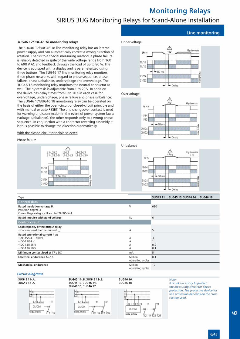
Line monitoring
3UG46 17/3UG46 18 monitoring relays
The 3UG46 17/3UG46 18 line monitoring relay has an internal power supply and can automatically correct a wrong direction of rotation. Thanks to a special measuring method, a phase failure is reliably detected in spite of the wide voltage range from 160 to 690 V AC and feedback through the load of up to 80 %. The device is equipped with a display and is parameterized using three buttons. The 3UG46 17 line monitoring relay monitors three-phase networks with regard to phase sequence, phase failure, phase unbalance, undervoltage and overvoltage. The 3UG46 18 monitoring relay monitors the neutral conductor as well. The hysteresis is adjustable from 1 to 20 V. In addition the device has delay times from 0 to 20 s in each case for overvoltage, undervoltage, phase failure and phase unbalance. The 3UG46 17/3UG46 18 monitoring relay can be operated on the basis of either the open-circuit or closed-circuit principle and with manual or auto RESET. The one changeover contact is used for warning or disconnection in the event of power system faults (voltage, unbalance), the other responds only to a wrong phase sequence. In conjunction with a contactor reversing assembly it is thus possible to change the direction automatically.
With the closed-circuit principle selected
Phase failure
Undervoltage
Overvoltage
Unbalance
Type 3UG45 11 ... 3UG45 13, 3UG46 14 ... 3UG46 18
General dataRated insulation voltage Ui
Pollution degree 3Overvoltage category III acc. to EN 60664-1
V 690
Rated impulse withstand voltage kV 6
Control circuit
Load capacity of the output relay• Conventional thermal current Ith
A
5
Rated operational current Ie at• AC-15/24 ... 400 V• DC-13/24 V• DC-13/125 V• DC-13/250 V
AAAA
310.20.1
Minimum contact load at 17 V DC mA 5
Electrical endurance AC-15 Million operating cycles
0.1
Mechanical endurance Million operating cycles
10
Circuit diagrams
3UG45 11-.A,3UG45 12-.A
3UG45 11-.B, 3UG45 12-.B,3UG45 13, 3UG46 14,3UG46 15, 3UG46 17
3UG46 16,3UG46 18
Note: It is not necessary to protect the measuring circuit for device protection. The protective device for line protection depends on the cross-section used.
Monitoring RelaysSIRIUS 3UG Monitoring Relays for Stand-Alone Installation
6/43
6
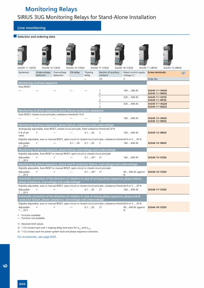
Line monitoring
Selection and ordering data
3UG45 11-1AP20 3UG46 15-1CR20 3UG46 16-1CR20 3UG46 17-1CR20 3UG46 18-1CR20 3UG45 11-2BP20 3UG45 12-2BR20
Hysteresis Undervoltage detection
Overvoltage detection
ON-delay Tripping delay
Version of auxiliary contacts
Rated control supply voltage Us
1)
Screw terminals
s s CO V Order No.
Monitoring of phase sequenceAuto-RESET
— — — — — 12
160 … 260 AC 3UG45 11-1AN203UG45 11-1BN20
12
320 … 500 AC 3UG45 11-1AP203UG45 11-1BP20
12
420 … 690 AC 3UG45 11-1AQ203UG45 11-1BQ20
Monitoring of phase sequence, phase failure and phase unbalanceAuto-RESET, closed-circuit principle, unbalance threshold 10 %
— — — — — 12
160 … 690 AC 3UG45 12-1AR203UG45 12-1BR20
Monitoring of phase sequence, phase failure, unbalance and undervoltage Analogically adjustable, Auto-RESET, closed-circuit principle, fixed unbalance threshold 20 %
5 % of set value
— — 0.1 … 20 2 160 … 690 AC 3UG45 13-1BR20
Digitally adjustable, auto or manual RESET, open-circuit or closed-circuit principle, unbalance threshold 0 or 5 ... 20 %
Adjustable 1 ... 20 V
— 0.1 ... 20 0.1 … 20 2 160 … 690 AC 3UG46 14-1BR20
Monitoring of phase sequence, phase failure, overvoltage and undervoltage Digitally adjustable, Auto-RESET or manual RESET, open-circuit or closed-circuit principle
Adjustable 1 ... 20 V
— 0.1 … 202) 22) 160 … 690 AC 3UG46 15-1CR20
Monitoring of phase sequence, phase and N conductor failure, overvoltage and undervoltage Digitally adjustable, Auto-RESET or manual RESET, open-circuit or closed-circuit principle
Adjustable 1 ... 20 V
— 0.1 … 202) 22) 90… 400 AC against N
3UG46 16-1CR20
Automatic correction of the direction of rotation in case of wrong phase sequence, phase failure, phase unbalance, overvoltage and undervoltage Digitally adjustable, auto or manual RESET, open-circuit or closed-circuit principle, unbalance threshold 0 or 5 ... 20 %
Adjustable 1 ... 20 V
— 0.1 … 20 23) 160 … 690 AC 3UG46 17-1CR20
Automatic correction of the direction of rotation in case of wrong phase sequence, phase and N conductor failure, phase unbalance, overvoltage and undervoltage Digitally adjustable, auto or manual RESET, open-circuit or closed-circuit principle, unbalance threshold 0 or 5 ... 20 %
Adjustable 1 ... 20 V
— 0.1 … 20 23) 90… 400 AC against N
3UG46 18-1CR20
Function available— Function not available
1) Absolute limit values.
2) 1 CO contact each and 1 tripping delay time each for Umin and Umax.
3) 1 CO contact each for power system fault and phase sequence correction.
For accessories, see page 6/65.
Monitoring RelaysSIRIUS 3UG Monitoring Relays for Stand-Alone Installation
6/44
6
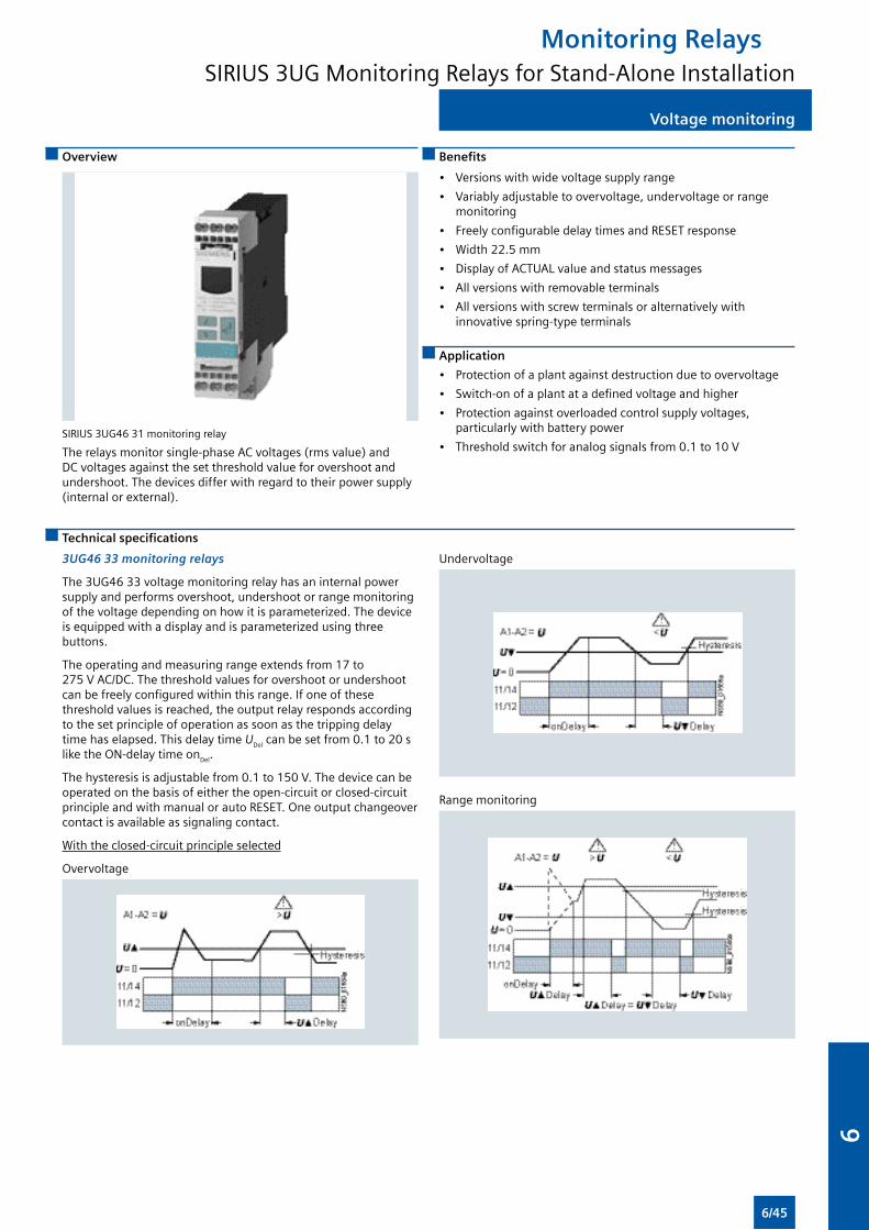
Voltage monitoring
Overview
SIRIUS 3UG46 31 monitoring relay
The relays monitor single-phase AC voltages (rms value) and DC voltages against the set threshold value for overshoot and undershoot. The devices differ with regard to their power supply (internal or external).
Benefits
• Versions with wide voltage supply range
• Variably adjustable to overvoltage, undervoltage or range monitoring
• Freely configurable delay times and RESET response
• Width 22.5 mm
• Display of ACTUAL value and status messages
• All versions with removable terminals
• All versions with screw terminals or alternatively with innovative spring-type terminals
Application
• Protection of a plant against destruction due to overvoltage
• Switch-on of a plant at a defined voltage and higher
• Protection against overloaded control supply voltages, particularly with battery power
• Threshold switch for analog signals from 0.1 to 10 V
Technical specifications
3UG46 33 monitoring relays
The 3UG46 33 voltage monitoring relay has an internal power supply and performs overshoot, undershoot or range monitoring of the voltage depending on how it is parameterized. The device is equipped with a display and is parameterized using three buttons.
The operating and measuring range extends from 17 to 275 V AC/DC. The threshold values for overshoot or undershoot can be freely configured within this range. If one of these threshold values is reached, the output relay responds according to the set principle of operation as soon as the tripping delay time has elapsed. This delay time UDel can be set from 0.1 to 20 s like the ON-delay time onDel.
The hysteresis is adjustable from 0.1 to 150 V. The device can be operated on the basis of either the open-circuit or closed-circuit principle and with manual or auto RESET. One output changeover contact is available as signaling contact.
With the closed-circuit principle selected
Overvoltage
Undervoltage
Range monitoring
Monitoring RelaysSIRIUS 3UG Monitoring Relays for Stand-Alone Installation
6/45
6
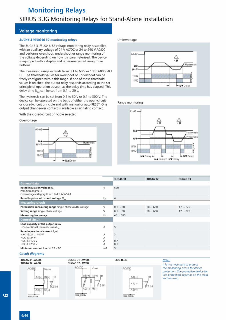
Voltage monitoring
3UG46 31/3UG46 32 monitoring relays
The 3UG46 31/3UG46 32 voltage monitoring relay is supplied with an auxiliary voltage of 24 V AC/DC or 24 to 240 V AC/DC and performs overshoot, undershoot or range monitoring of the voltage depending on how it is parameterized. The device is equipped with a display and is parameterized using three buttons.
The measuring range extends from 0.1 to 60 V or 10 to 600 V AC/DC. The threshold values for overshoot or undershoot can be freely configured within this range. If one of these threshold values is reached, the output relay responds according to the set principle of operation as soon as the delay time has elapsed. This delay time UDel can be set from 0.1 to 20 s.
The hysteresis can be set from 0.1 to 30 V or 0.1 to 300 V. The device can be operated on the basis of either the open-circuit or closed-circuit principle and with manual or auto RESET. One output changeover contact is available as signaling contact.
With the closed-circuit principle selected
Overvoltage
Undervoltage
Range monitoring
3UG46 31 3UG46 32 3UG46 33
General data
Rated insulation voltage Ui
Pollution degree 3Overvoltage category III acc. to EN 60664-1
V 690
Rated impulse withstand voltage Uimp kV 6
Measuring circuit
Permissible measuring range single-phase AC/DC voltage V 0.1 … 68 10 … 650 17 … 275
Setting range single-phase voltage V 0.1 ... 60 10 ... 600 17 ... 275
Measuring frequency Hz 40 ... 500
Control circuit
Load capacity of the output relay• Conventional thermal current Ith
A
5
Rated operational current Ie at• AC-15/24 ... 400 V• DC-13/24 V• DC-13/125 V• DC-13/250 V
AAAA
310.20.1
Minimum contact load at 17 V DC mA 5
Circuit diagrams
3UG46 31-.AA30, 3UG46 32-.AA30
3UG46 31-.AW30, 3UG46 32-.AW30
3UG46 33 Note:
It is not necessary to protect the measuring circuit for device protection. The protective device for line protection depends on the cross-section used.
Monitoring RelaysSIRIUS 3UG Monitoring Relays for Stand-Alone Installation
6/46
6
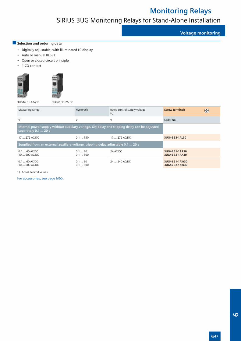
Voltage monitoring
Selection and ordering data
• Digitally adjustable, with illuminated LC display
• Auto or manual RESET
• Open or closed-circuit principle
• 1 CO contact
3UG46 31-1AA30 3UG46 33-2AL30
Measuring range Hysteresis Rated control supply voltage Us
Screw terminals
V V V Order No.
Internal power supply without auxiliary voltage, ON-delay and tripping delay can be adjusted separately 0.1 ... 20 s
17 … 275 AC/DC 0.1 ... 150 17 … 275 AC/DC1) 3UG46 33-1AL30
Supplied from an external auxiliary voltage, tripping delay adjustable 0.1 ... 20 s
0.1 … 60 AC/DC10 … 600 AC/DC
0.1 ... 300.1 ... 300
24 AC/DC 3UG46 31-1AA303UG46 32-1AA30
0.1 … 60 AC/DC10 … 600 AC/DC
0.1 ... 300.1 ... 300
24 … 240 AC/DC 3UG46 31-1AW303UG46 32-1AW30
1) Absolute limit values.
For accessories, see page 6/65.
Monitoring RelaysSIRIUS 3UG Monitoring Relays for Stand-Alone Installation
6/47
6
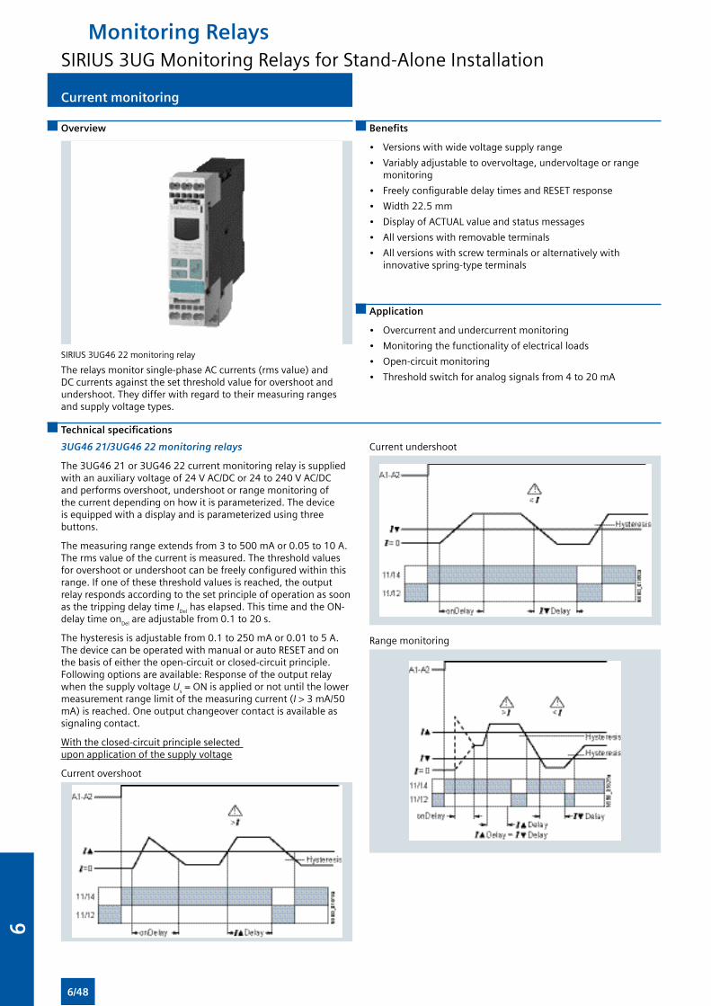
Current monitoring
Overview
SIRIUS 3UG46 22 monitoring relay
The relays monitor single-phase AC currents (rms value) and DC currents against the set threshold value for overshoot and undershoot. They differ with regard to their measuring ranges and supply voltage types.
Benefits
• Versions with wide voltage supply range
• Variably adjustable to overvoltage, undervoltage or range monitoring
• Freely configurable delay times and RESET response
• Width 22.5 mm
• Display of ACTUAL value and status messages
• All versions with removable terminals
• All versions with screw terminals or alternatively with innovative spring-type terminals
Application
• Overcurrent and undercurrent monitoring
• Monitoring the functionality of electrical loads
• Open-circuit monitoring
• Threshold switch for analog signals from 4 to 20 mA
Technical specifications
3UG46 21/3UG46 22 monitoring relays
The 3UG46 21 or 3UG46 22 current monitoring relay is supplied with an auxiliary voltage of 24 V AC/DC or 24 to 240 V AC/DC and performs overshoot, undershoot or range monitoring of the current depending on how it is parameterized. The device is equipped with a display and is parameterized using three buttons.
The measuring range extends from 3 to 500 mA or 0.05 to 10 A. The rms value of the current is measured. The threshold values for overshoot or undershoot can be freely configured within this range. If one of these threshold values is reached, the output relay responds according to the set principle of operation as soon as the tripping delay time IDel has elapsed. This time and the ON-delay time onDel are adjustable from 0.1 to 20 s.
The hysteresis is adjustable from 0.1 to 250 mA or 0.01 to 5 A. The device can be operated with manual or auto RESET and on the basis of either the open-circuit or closed-circuit principle. Following options are available: Response of the output relay when the supply voltage Us = ON is applied or not until the lower measurement range limit of the measuring current (I > 3 mA/50 mA) is reached. One output changeover contact is available as signaling contact.
With the closed-circuit principle selected upon application of the supply voltage
Current overshoot
Current undershoot
Range monitoring
Monitoring RelaysSIRIUS 3UG Monitoring Relays for Stand-Alone Installation
6/48
6
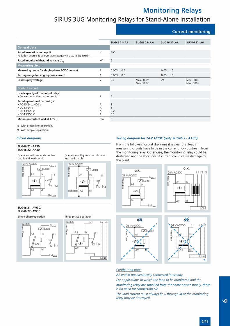
Current monitoring
3UG46 21-.AA 3UG46 21-.AW 3UG46 22-.AA 3UG46 22-.AW
General data
Rated insulation voltage Ui
Pollution degree 3; overvoltage category III acc. to EN 60664-1V 690
Rated impulse withstand voltage Uimp kV 6
Measuring circuit
Measuring range for single-phase AC/DC current A 0.003 … 0.6 0.05 … 15
Setting range for single-phase current A 0.003 ... 0.5 0.05 ... 10
Load supply voltage V 24 Max. 3001)
Max. 5002)
24 Max. 3001)
Max. 5002)
Control circuit
Load capacity of the output relay• Conventional thermal current Ith A 5
Rated operational current Ie at• AC-15/24 ... 400 V• DC-13/24 V• DC-13/125 V• DC-13/250 V
AAAA
310.20.1
Minimum contact load at 17 V DC mA 5
1) With protective separation.
2) With simple separation.
Circuit diagrams
3UG46 21-.AA30,3UG46 22-.AA30
Operation with separate control circuit and load circuit
Operation with joint control circuit and load circuit
3UG46 21-.AW30, 3UG46 22-.AW30
Single-phase operation Three-phase operation
Wiring diagram for 24 V AC/DC (only 3UG46 2.-.AA30)
From the following circuit diagrams it is clear that loads in measuring circuits have to be in the current flow upstream from the monitoring relay. Otherwise, the monitoring relay could be destroyed and the short-circuit current could cause damage to the plant.
Configuring note:
A2 and M are electrically connected internally.
For applications in which the load to be monitored and the
monitoring relay are supplied from the same power supply, there is no need for connection A2.
The load current must always flow through M or the monitoring relay may be destroyed.
Monitoring RelaysSIRIUS 3UG Monitoring Relays for Stand-Alone Installation
6/49
6
Current monitoring
Selection and ordering data
• Digitally adjustable, with illuminated LC display
• Auto or manual RESET
• Open or closed-circuit principle
• 1 CO contact
3UG46 21-1AA30 3UG46 22-2AW30
Measuring range Hysteresis Rated control supply voltage Us Screw terminals
V Order No.
Monitoring of undercurrent and overcurrent, ON-delay and tripping delay can be adjusted separately 0.1 ... 20 s
AC/DC 3 … 500 mAAC/DC 0.05 … 10 A
0.1 ... 250 mA0.01 ... 5 A
24 AC/DC1) 3UG46 21-1AA303UG46 22-1AA30
AC/DC 3 … 500 mAAC/DC 0.05 … 10 A
0.1 ... 250 mA0.01 ... 5 A
24 … 240 AC/DC2) 3UG46 21-1AW303UG46 22-1AW30
1) No electrical separation. Load supply voltage 24 V.
2) Electrical separation between control circuit and measuring circuit. Load supply voltage for protective separation max. 300 V, for simple isolation max. 500 V.
For accessories, see page 6/65.
With AC currents I > 10 A it is possible to use 4NC current transformers as an accessory.
Monitoring RelaysSIRIUS 3UG Monitoring Relays for Stand-Alone Installation
6/50
6
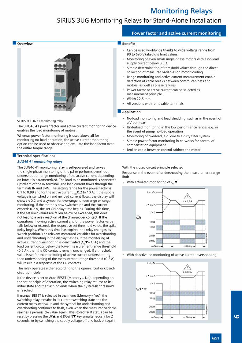
Power factor and active current monitoring
Overview
SIRIUS 3UG46 41 monitoring relay
The 3UG46 41 power factor and active current monitoring device enables the load monitoring of motors.
Whereas power factor monitoring is used above all for monitoring no-load operation, the active current monitoring option can be used to observe and evaluate the load factor over the entire torque range.
Benefits
• Can be used worldwide thanks to wide voltage range from 90 to 690 V (absolute limit values)
• Monitoring of even small single-phase motors with a no-load supply current below 0.5 A
• Simple determination of threshold values through the direct collection of measured variables on motor loading
• Range monitoring and active current measurement enable detection of cable breaks between control cabinets and motors, as well as phase failures
• Power factor or active current can be selected as measurement principle
• Width 22.5 mm• All versions with removable terminals
Application
• No-load monitoring and load shedding, such as in the event of a V-belt tear
• Underload monitoring in the low performance range, e.g. in the event of pump no-load operation
• Monitoring of overload, e.g. due to a dirty filter system• Simple power factor monitoring in networks for control of
compensation equipment• Broken cable between control cabinet and motor
Technical specifications
3UG46 41 monitoring relays
With the closed-circuit principle selected
Response in the event of undershooting the measurement range limit
• With activated monitoring of Irest
• With deactivated monitoring of active current overshooting
The 3UG46 41 monitoring relay is self-powered and serves the single-phase monitoring of the p.f or performs overshoot, undershoot or range monitoring of the active current depending on how it is parameterized. The load to be monitored is connected upstream of the IN terminal. The load current flows through the terminals IN and Ly/N. The setting range for the power factor is 0.1 to 0.99 and for the active current Ires 0.2 to 10 A. If the supply voltage is switched on and no load current flows, the display will show I < 0.2 and a symbol for overrange, underrange or range monitoring. If the motor is now switched on and the current exceeds 0.2 A, the set ON delay time begins. During this time, if the set limit values are fallen below or exceeded, this does not lead to a relay reaction of the changeover contact. If the operational flowing active current and/or the power factor value falls below or exceeds the respective set threshold value, the spike delay begins. When this time has expired, the relay changes its switch position. The relevant measured variables for overshooting and undershooting in the display flashes. If the monitoring of active current overshooting is deactivated (Irest= OFF) and the load current drops below the lower measurement range threshold (0.2 A), then the CO contacts remain unchanged. If a threshold value is set for the monitoring of active current undershooting, then undershooting of the measurement range threshold (0.2 A) will result in a response of the CO contacts.
The relay operates either according to the open-circuit or closed-circuit principle.
If the device is set to Auto-RESET (Memory = No), depending on the set principle of operation, the switching relay returns to its initial state and the flashing ends when the hysteresis threshold is reached.
If manual RESET is selected in the menu (Memory = Yes), the switching relay remains in its current switching state and the current measured value and the symbol for undershooting and overshooting continues to flash, even when the measured variable reaches a permissible value again. This stored fault status can be reset by pressing the UP and DOWNt key simultaneously for 2 seconds, or by switching the supply voltage off and back on again.
Monitoring RelaysSIRIUS 3UG Monitoring Relays for Stand-Alone Installation
6/51
6
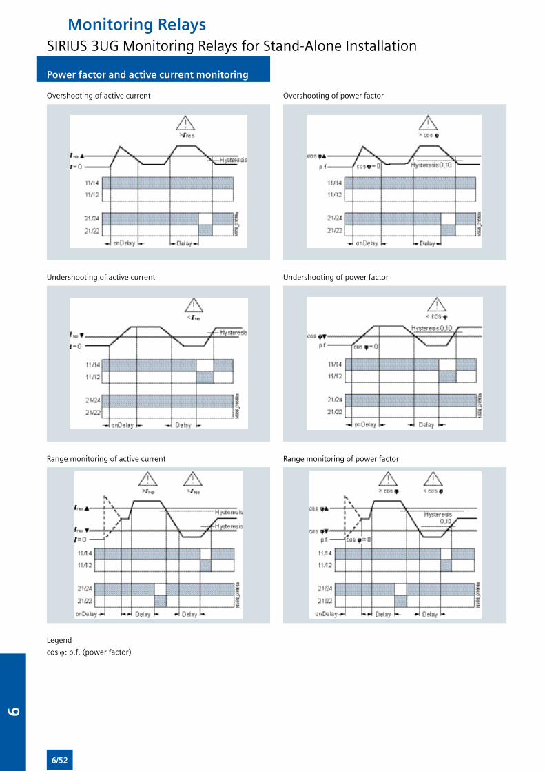
Power factor and active current monitoring
Overshooting of active current
Undershooting of active current
Range monitoring of active current
Legend
cos j: p.f. (power factor)
Overshooting of power factor
Undershooting of power factor
Range monitoring of power factor
Monitoring RelaysSIRIUS 3UG Monitoring Relays for Stand-Alone Installation
6/52
6
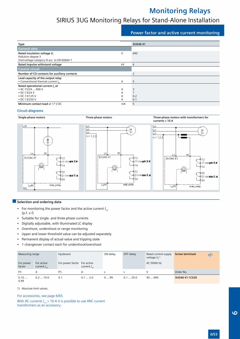
Type 3UG46 41
General dataRated insulation voltage Ui
Pollution degree 3Overvoltage category III acc. to EN 60664-1
V 690
Rated impulse withstand voltage kV 6
Control circuit
Number of CO contacts for auxiliary contacts 2
Load capacity of the output relay• Conventional thermal current Ith
A
5
Rated operational current Ie at• AC-15/24 ... 400 V• DC-13/24 V• DC-13/125 V• DC-13/250 V
AAAA
310.20.1
Minimum contact load at 17 V DC mA 5
Circuit diagrams
Single-phase motors Three-phase motors Three-phase motors with transformers for currents > 10 A
Selection and ordering data
• For monitoring the power factor and the active current Ires
(p.f. x I)
• Suitable for single- and three-phase currents
• Digitally adjustable, with illuminated LC display
• Overshoot, undershoot or range monitoring
• Upper and lower threshold value can be adjusted separately
• Permanent display of actual value and tripping state
• 1 changeover contact each for undershoot/overshoot
Measuring range Hysteresis ON-delay OFF-delay Rated control supply voltage Us
1)
Screw terminals
For power factor
For active current Ires
For power factor For active current Ires
AC 50/60 Hz
P.f. A P.f. A s s V Order No.
0.10 ... 0.99
0.2 ... 10.0 0.1 0.1 ... 2.0 0 ... 99 0.1 ... 20.0 90 ... 690 3UG46 41-1CS20
1) Absolute limit values.
For accessories, see page 6/65.
With AC currents Ires > 10 A it is possible to use 4NC current transformers as an accessory.
Power factor and active current monitoring
Monitoring RelaysSIRIUS 3UG Monitoring Relays for Stand-Alone Installation
6/53
6
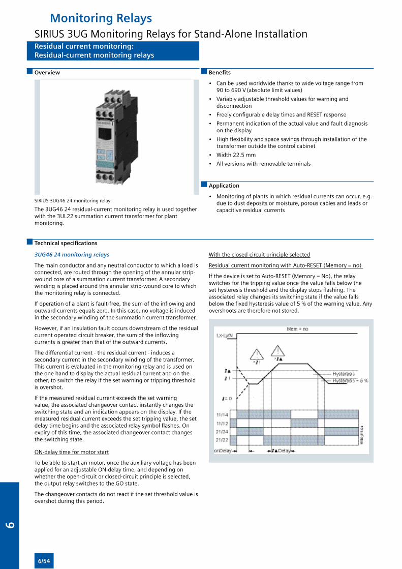
Residual current monitoring:Residual-current monitoring relays
Overview
SIRIUS 3UG46 24 monitoring relay
The 3UG46 24 residual-current monitoring relay is used together with the 3UL22 summation current transformer for plant monitoring.
Benefits
• Can be used worldwide thanks to wide voltage range from 90 to 690 V (absolute limit values)
• Variably adjustable threshold values for warning and disconnection
• Freely configurable delay times and RESET response
• Permanent indication of the actual value and fault diagnosis on the display
• High flexibility and space savings through installation of the transformer outside the control cabinet
• Width 22.5 mm
• All versions with removable terminals
Application
• Monitoring of plants in which residual currents can occur, e.g. due to dust deposits or moisture, porous cables and leads or capacitive residual currents
Technical specifications
3UG46 24 monitoring relays
The main conductor and any neutral conductor to which a load is connected, are routed through the opening of the annular strip-wound core of a summation current transformer. A secondary winding is placed around this annular strip-wound core to which the monitoring relay is connected.
If operation of a plant is fault-free, the sum of the inflowing and outward currents equals zero. In this case, no voltage is induced in the secondary winding of the summation current transformer.
However, if an insulation fault occurs downstream of the residual current operated circuit breaker, the sum of the inflowing currents is greater than that of the outward currents.
The differential current - the residual current - induces a secondary current in the secondary winding of the transformer. This current is evaluated in the monitoring relay and is used on the one hand to display the actual residual current and on the other, to switch the relay if the set warning or tripping threshold is overshot.
If the measured residual current exceeds the set warning value, the associated changeover contact instantly changes the switching state and an indication appears on the display. If the measured residual current exceeds the set tripping value, the set delay time begins and the associated relay symbol flashes. On expiry of this time, the associated changeover contact changes the switching state.
ON-delay time for motor start
To be able to start an motor, once the auxiliary voltage has been applied for an adjustable ON-delay time, and depending on whether the open-circuit or closed-circuit principle is selected, the output relay switches to the GO state.
The changeover contacts do not react if the set threshold value is overshot during this period.
With the closed-circuit principle selected
Residual current monitoring with Auto-RESET (Memory = no)
If the device is set to Auto-RESET (Memory = No), the relay switches for the tripping value once the value falls below the set hysteresis threshold and the display stops flashing. The associated relay changes its switching state if the value falls below the fixed hysteresis value of 5 % of the warning value. Any overshoots are therefore not stored.
Monitoring RelaysSIRIUS 3UG Monitoring Relays for Stand-Alone Installation
6/54
6
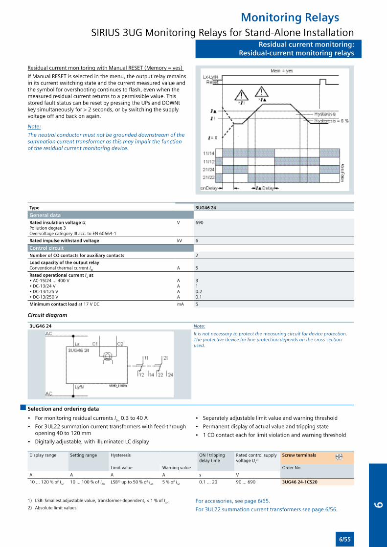
Residual current monitoring:Residual-current monitoring relays
Residual current monitoring with Manual RESET (Memory = yes)
If Manual RESET is selected in the menu, the output relay remains in its current switching state and the current measured value and the symbol for overshooting continues to flash, even when the measured residual current returns to a permissible value. This stored fault status can be reset by pressing the UPs and DOWNt key simultaneously for > 2 seconds, or by switching the supply voltage off and back on again.
Note:
The neutral conductor must not be grounded downstream of the summation current transformer as this may impair the function of the residual current monitoring device.
Type 3UG46 24
General dataRated insulation voltage Ui
Pollution degree 3Overvoltage category III acc. to EN 60664-1
V 690
Rated impulse withstand voltage kV 6
Control circuit
Number of CO contacts for auxiliary contacts 2
Load capacity of the output relayConventional thermal current Ith
A
5
Rated operational current Ie at• AC-15/24 ... 400 V• DC-13/24 V• DC-13/125 V• DC-13/250 V
AAAA
310.20.1
Minimum contact load at 17 V DC mA 5
Circuit diagram
3UG46 24 Note:
It is not necessary to protect the measuring circuit for device protection. The protective device for line protection depends on the cross-section used.
Selection and ordering data
• For monitoring residual currents IDn 0.3 to 40 A
• For 3UL22 summation current transformers with feed-through opening 40 to 120 mm
• Digitally adjustable, with illuminated LC display
• Separately adjustable limit value and warning threshold
• Permanent display of actual value and tripping state
• 1 CO contact each for limit violation and warning threshold
Display range Setting range Hysteresis
ON / tripping delay time
Rated control supply voltage Us
2)
Screw terminals
Limit value Warning value Order No.
A A A A s V
10 ... 120 % of I∆n 10 ... 100 % of I∆n LSB1) up to 50 % of I∆n 5 % of I∆n 0.1 ... 20 90 ... 690 3UG46 24-1CS20
1) LSB: Smallest adjustable value, transformer-dependent, ≤ 1 % of I∆n.
2) Absolute limit values.
For accessories, see page 6/65.
For 3UL22 summation current transformers see page 6/56.
Monitoring RelaysSIRIUS 3UG Monitoring Relays for Stand-Alone Installation
6/55
6
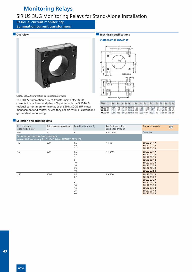
Residual current monitoring:Summation current transformers
Overview
SIRIUS 3UL22 summation current transformers
The 3UL22 summation current transformers detect fault currents in machines and plants. Together with the 3UG46 24 residual-current monitoring relay or the SIMOCODE 3UF motor management and control device they enable residual-current and ground-fault monitoring.
Technical specifications
Dimensional drawings
Selection and ordering data
Feed-through openingdiameter
Rated insulation voltage Ui
Rated fault current I∆n For Protodur cable, can be fed through
Screw terminals
mm V A max. mm2 Order No.
Summation current transformers (essential accessory for 3UG46 24 or SIMOCODE 3UF)40 690 0.3
0.51
4 x 95 3UL22 01-1A3UL22 01-2A3UL22 01-3A
65 690 0.30.51610162540
4 x 240 3UL22 02-1A3UL22 02-2A3UL22 02-3A3UL22 02-1B3UL22 02-2B3UL22 02-3B3UL22 02-4B3UL22 02-5B
120 1000 0.30.51610162540
8 x 300 3UL22 03-1A3UL22 03-2A3UL22 03-3A3UL22 03-1B3UL22 03-2B3UL22 03-3B3UL22 03-4B3UL22 03-5B
Monitoring RelaysSIRIUS 3UG Monitoring Relays for Stand-Alone Installation
6/56
6
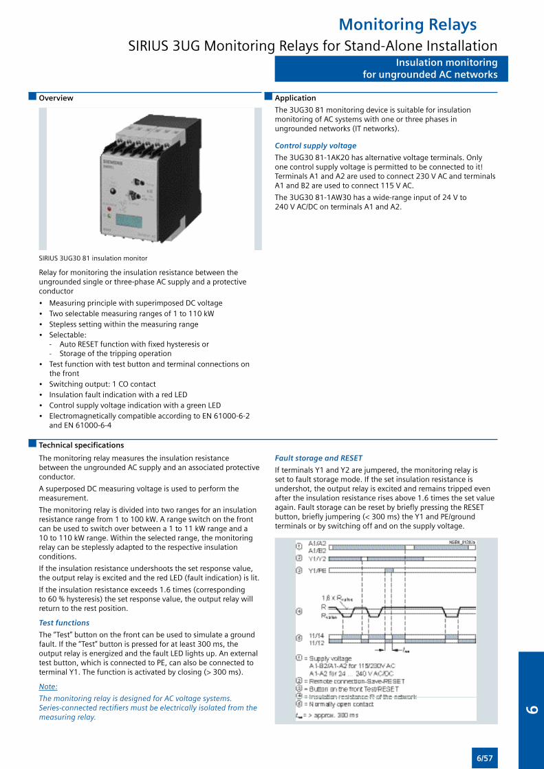
Insulation monitoringfor ungrounded AC networks
Overview Application
The 3UG30 81 monitoring device is suitable for insulation monitoring of AC systems with one or three phases in ungrounded networks (IT networks).
Control supply voltage
The 3UG30 81-1AK20 has alternative voltage terminals. Only one control supply voltage is permitted to be connected to it! Terminals A1 and A2 are used to connect 230 V AC and terminals A1 and B2 are used to connect 115 V AC.
The 3UG30 81-1AW30 has a wide-range input of 24 V to 240 V AC/DC on terminals A1 and A2.
SIRIUS 3UG30 81 insulation monitor
Relay for monitoring the insulation resistance between the ungrounded single or three-phase AC supply and a protective conductor
• Measuring principle with superimposed DC voltage• Two selectable measuring ranges of 1 to 110 kW• Stepless setting within the measuring range• Selectable: - Auto RESET function with fixed hysteresis or - Storage of the tripping operation• Test function with test button and terminal connections on
the front• Switching output: 1 CO contact• Insulation fault indication with a red LED• Control supply voltage indication with a green LED• Electromagnetically compatible according to EN 61000-6-2
and EN 61000-6-4
Technical specifications
The monitoring relay measures the insulation resistance between the ungrounded AC supply and an associated protective conductor.
A superposed DC measuring voltage is used to perform the measurement.
The monitoring relay is divided into two ranges for an insulation resistance range from 1 to 100 kW. A range switch on the front can be used to switch over between a 1 to 11 kW range and a 10 to 110 kW range. Within the selected range, the monitoring relay can be steplessly adapted to the respective insulation conditions.
If the insulation resistance undershoots the set response value, the output relay is excited and the red LED (fault indication) is lit.
If the insulation resistance exceeds 1.6 times (corresponding to 60 % hysteresis) the set response value, the output relay will return to the rest position.
Test functions
The “Test” button on the front can be used to simulate a ground fault. If the “Test” button is pressed for at least 300 ms, the output relay is energized and the fault LED lights up. An external test button, which is connected to PE, can also be connected to terminal Y1. The function is activated by closing (> 300 ms).
Note:
The monitoring relay is designed for AC voltage systems. Series-connected rectifiers must be electrically isolated from the measuring relay.
Fault storage and RESET
If terminals Y1 and Y2 are jumpered, the monitoring relay is set to fault storage mode. If the set insulation resistance is undershot, the output relay is excited and remains tripped even after the insulation resistance rises above 1.6 times the set value again. Fault storage can be reset by briefly pressing the RESET button, briefly jumpering (< 300 ms) the Y1 and PE/ground terminals or by switching off and on the supply voltage.
Monitoring RelaysSIRIUS 3UG Monitoring Relays for Stand-Alone Installation
6/57
6
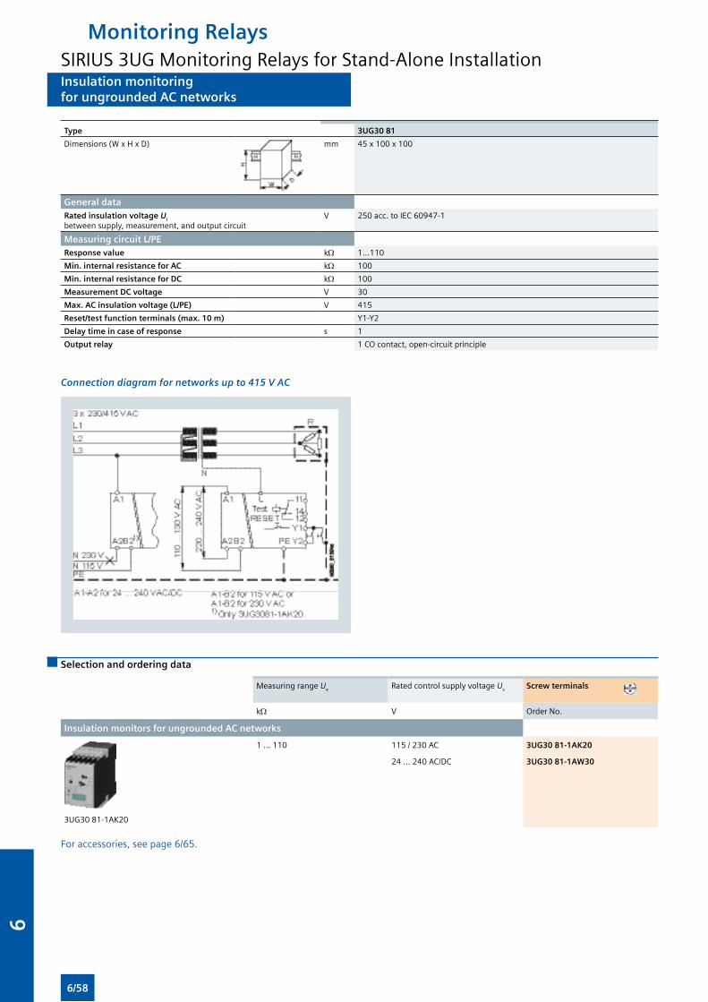
Insulation monitoringfor ungrounded AC networks
Type 3UG30 81
Dimensions (W x H x D) mm 45 x 100 x 100
General data
Rated insulation voltage Ui between supply, measurement, and output circuit
V 250 acc. to IEC 60947-1
Measuring circuit L/PE
Response value kΩ 1...110
Min. internal resistance for AC kΩ 100
Min. internal resistance for DC kΩ 100
Measurement DC voltage V 30
Max. AC insulation voltage (L/PE) V 415
Reset/test function terminals (max. 10 m) Y1-Y2
Delay time in case of response s 1
Output relay 1 CO contact, open-circuit principle
Connection diagram for networks up to 415 V AC
Selection and ordering data
Measuring range Ue Rated control supply voltage Us Screw terminals
kΩ V Order No.
Insulation monitors for ungrounded AC networks
3UG30 81-1AK20
1 ... 110 115 / 230 AC 3UG30 81-1AK20
24 ... 240 AC/DC 3UG30 81-1AW30
For accessories, see page 6/65.
Monitoring RelaysSIRIUS 3UG Monitoring Relays for Stand-Alone Installation
6/58
6
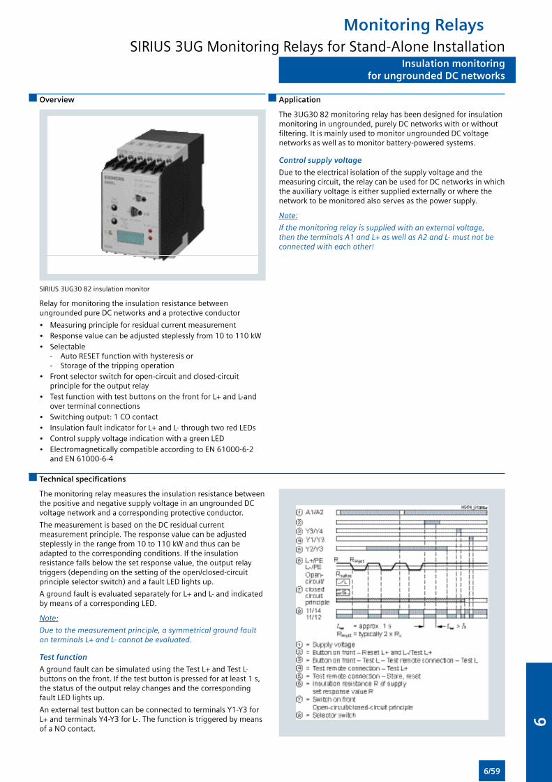
Insulation monitoringfor ungrounded DC networks
Overview
SIRIUS 3UG30 82 insulation monitor
Relay for monitoring the insulation resistance between ungrounded pure DC networks and a protective conductor
• Measuring principle for residual current measurement• Response value can be adjusted steplessly from 10 to 110 kW• Selectable - Auto RESET function with hysteresis or - Storage of the tripping operation • Front selector switch for open-circuit and closed-circuit
principle for the output relay• Test function with test buttons on the front for L+ and L-and
over terminal connections• Switching output: 1 CO contact• Insulation fault indicator for L+ and L- through two red LEDs• Control supply voltage indication with a green LED • Electromagnetically compatible according to EN 61000-6-2
and EN 61000-6-4
Application
The 3UG30 82 monitoring relay has been designed for insulation monitoring in ungrounded, purely DC networks with or without filtering. It is mainly used to monitor ungrounded DC voltage networks as well as to monitor battery-powered systems.
Control supply voltage
Due to the electrical isolation of the supply voltage and the measuring circuit, the relay can be used for DC networks in which the auxiliary voltage is either supplied externally or where the network to be monitored also serves as the power supply.
Note:
If the monitoring relay is supplied with an external voltage, then the terminals A1 and L+ as well as A2 and L- must not be connected with each other!
Technical specifications
The monitoring relay measures the insulation resistance between the positive and negative supply voltage in an ungrounded DC voltage network and a corresponding protective conductor.
The measurement is based on the DC residual current measurement principle. The response value can be adjusted steplessly in the range from 10 to 110 kW and thus can be adapted to the corresponding conditions. If the insulation resistance falls below the set response value, the output relay triggers (depending on the setting of the open/closed-circuit principle selector switch) and a fault LED lights up.
A ground fault is evaluated separately for L+ and L- and indicated by means of a corresponding LED.
Note:
Due to the measurement principle, a symmetrical ground fault on terminals L+ and L- cannot be evaluated.
Test function
A ground fault can be simulated using the Test L+ and Test L- buttons on the front. If the test button is pressed for at least 1 s, the status of the output relay changes and the corresponding fault LED lights up.
An external test button can be connected to terminals Y1-Y3 for L+ and terminals Y4-Y3 for L-. The function is triggered by means of a NO contact.
Monitoring RelaysSIRIUS 3UG Monitoring Relays for Stand-Alone Installation
6/59
6
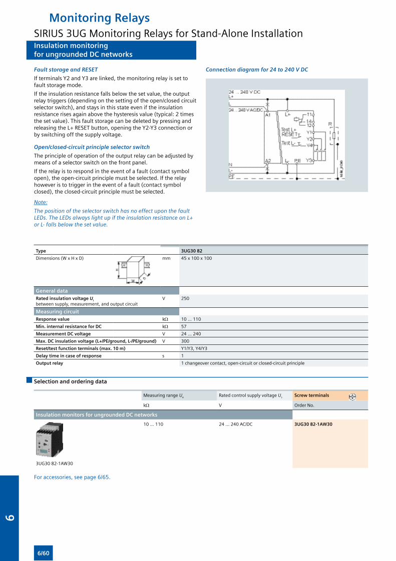
Insulation monitoringfor ungrounded DC networks
Fault storage and RESET
If terminals Y2 and Y3 are linked, the monitoring relay is set to fault storage mode.
If the insulation resistance falls below the set value, the output relay triggers (depending on the setting of the open/closed circuit selector switch), and stays in this state even if the insulation resistance rises again above the hysteresis value (typical: 2 times the set value). This fault storage can be deleted by pressing and releasing the L+ RESET button, opening the Y2-Y3 connection or by switching off the supply voltage.
Open/closed-circuit principle selector switch
The principle of operation of the output relay can be adjusted by means of a selector switch on the front panel.
If the relay is to respond in the event of a fault (contact symbol open), the open-circuit principle must be selected. If the relay however is to trigger in the event of a fault (contact symbol closed), the closed-circuit principle must be selected.
Note:
The position of the selector switch has no effect upon the fault LEDs. The LEDs always light up if the insulation resistance on L+ or L- falls below the set value.
Connection diagram for 24 to 240 V DC
Type 3UG30 82
Dimensions (W x H x D) mm 45 x 100 x 100
General data
Rated insulation voltage Ui between supply, measurement, and output circuit
V 250
Measuring circuit
Response value kΩ 10 ... 110
Min. internal resistance for DC kΩ 57
Measurement DC voltage V 24 ... 240
Max. DC insulation voltage (L+/PE/ground, L-/PE/ground) V 300
Reset/test function terminals (max. 10 m) Y1/Y3, Y4/Y3
Delay time in case of response s 1
Output relay 1 changeover contact, open-circuit or closed-circuit principle
Selection and ordering data
Measuring range Ue Rated control supply voltage Us Screw terminals
kΩ V Order No.
Insulation monitors for ungrounded DC networks
3UG30 82-1AW30
10 ... 110 24 ... 240 AC/DC 3UG30 82-1AW30
For accessories, see page 6/65.
Monitoring RelaysSIRIUS 3UG Monitoring Relays for Stand-Alone Installation
6/60
6

Level monitoring:Level monitoring relays
Overview Benefits
• Can be used worldwide thanks to wide voltage range from 24 to 240 V (absolute limit values)
• 2- and 3-pole wire electrodes can be individually shortened for simple mounting from above or below
• Bow electrodes for installing from the side, for higher filling heights and minimum space requirements
• Can be flexibly adapted to different conductive liquids through analog setting of the sensitivity from 2 to 200 kW
• Compensation of wave movements through a tripping delay time of 0.1 to 10 seconds
• Selectable inlet or outlet function
• All versions with removable terminals
• All versions with screw terminals or alternatively with innovative spring-type terminals
SIRIUS 3UG45 01 monitoring relay
The 3UG45 01 level monitoring relay is used together with 2- or 3-pole sensors to monitor the levels of conductive liquids.
Application
• Single-point and two-point level monitoring
• Overflow protection
• Dry run protection
• Leak monitoring
Technical specifications
3UG45 01 monitoring relays
The principle of operation of the 3UG45 01 level monitoring relay is based on measuring the electrical resistance of the liquid between two immersion sensors and a reference terminal. If the measured value is lower than the sensitivity set at the front, the output relay changes its switching state. In order to exclude electrolytic phenomena in the liquid, the sensors are supplied with alternating current.
Two-point control
The output relay changes its switching state as soon as the liquid level reaches the maximum sensor, while the minimum sensor is submerged. The relay returns to its original switching state as soon as the minimum sensor no longer has contact with the liquid.
OVER, two-point control
UNDER, two-point control
Note:
It is also possible to connect other resistance sensors to the Min and Max terminals in the range 2 to 200 kW, e.g. photoresistors, temperature sensors, encoders based on resistance, etc. The monitoring relay can therefore also be used for other applications apart from monitoring the levels of liquids.
Monitoring RelaysSIRIUS 3UG Monitoring Relays for Stand-Alone Installation
6/61
6
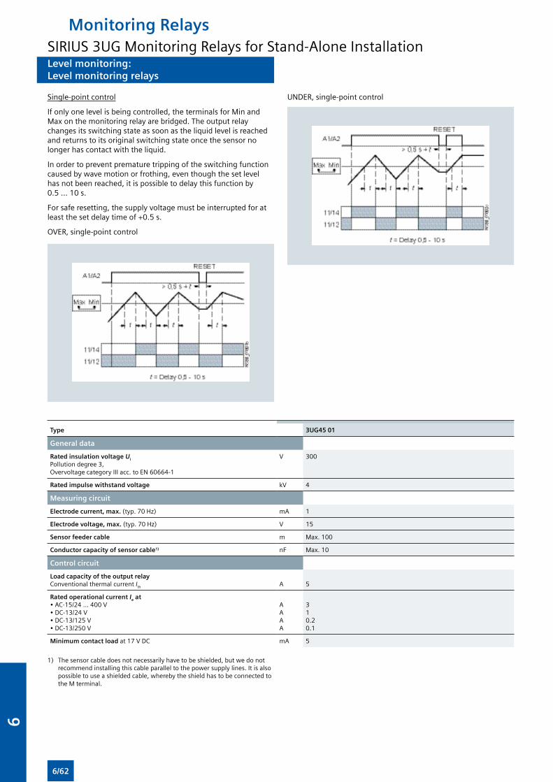
Level monitoring:Level monitoring relays
Single-point control
If only one level is being controlled, the terminals for Min and Max on the monitoring relay are bridged. The output relay changes its switching state as soon as the liquid level is reached and returns to its original switching state once the sensor no longer has contact with the liquid.
In order to prevent premature tripping of the switching function caused by wave motion or frothing, even though the set level has not been reached, it is possible to delay this function by 0.5 ... 10 s.
For safe resetting, the supply voltage must be interrupted for at least the set delay time of +0.5 s.
OVER, single-point control
UNDER, single-point control
Type 3UG45 01
General data
Rated insulation voltage Ui
Pollution degree 3, Overvoltage category III acc. to EN 60664-1
V 300
Rated impulse withstand voltage kV 4
Measuring circuit
Electrode current, max. (typ. 70 Hz) mA 1
Electrode voltage, max. (typ. 70 Hz) V 15
Sensor feeder cable m Max. 100
Conductor capacity of sensor cable1) nF Max. 10
Control circuit
Load capacity of the output relayConventional thermal current Ith
A
5
Rated operational current Ie at• AC-15/24 ... 400 V• DC-13/24 V• DC-13/125 V• DC-13/250 V
AAAA
310.20.1
Minimum contact load at 17 V DC mA 5
1) The sensor cable does not necessarily have to be shielded, but we do not recommend installing this cable parallel to the power supply lines. It is also possible to use a shielded cable, whereby the shield has to be connected to the M terminal.
Monitoring RelaysSIRIUS 3UG Monitoring Relays for Stand-Alone Installation
6/62
6
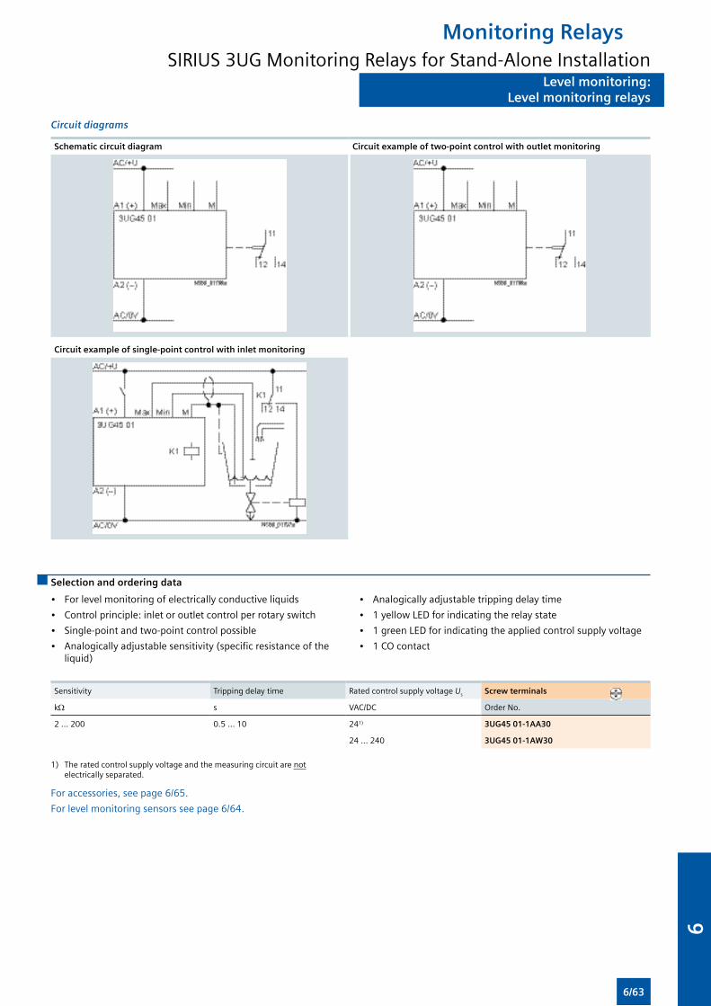
Level monitoring:Level monitoring relays
Circuit diagrams
Schematic circuit diagram Circuit example of two-point control with outlet monitoring
Circuit example of single-point control with inlet monitoring
Selection and ordering data
• For level monitoring of electrically conductive liquids
• Control principle: inlet or outlet control per rotary switch
• Single-point and two-point control possible
• Analogically adjustable sensitivity (specific resistance of the liquid)
• Analogically adjustable tripping delay time
• 1 yellow LED for indicating the relay state
• 1 green LED for indicating the applied control supply voltage
• 1 CO contact
Sensitivity Tripping delay time Rated control supply voltage Us Screw terminals
kΩ s VAC/DC Order No.
2 ... 200 0.5 ... 10 241) 3UG45 01-1AA30
24 ... 240 3UG45 01-1AW30
1) The rated control supply voltage and the measuring circuit are not electrically separated.
For accessories, see page 6/65.
For level monitoring sensors see page 6/64.
Monitoring RelaysSIRIUS 3UG Monitoring Relays for Stand-Alone Installation
6/63
6
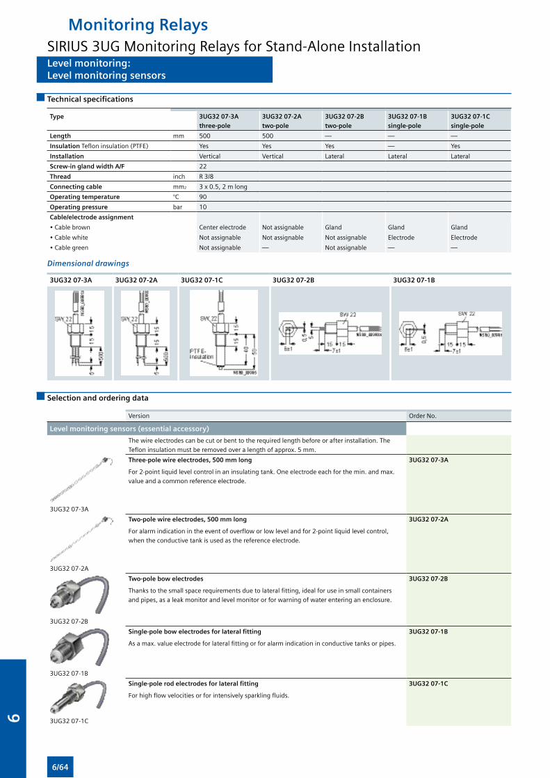
Level monitoring:Level monitoring sensors
Technical specifications
Type 3UG32 07-3A
three-pole
3UG32 07-2A
two-pole
3UG32 07-2B
two-pole
3UG32 07-1B
single-pole
3UG32 07-1C
single-pole
Length mm 500 500 — — —
Insulation Teflon insulation (PTFE) Yes Yes Yes — Yes
Installation Vertical Vertical Lateral Lateral Lateral
Screw-in gland width A/F 22
Thread inch R 3/8
Connecting cable mm2 3 x 0.5, 2 m long
Operating temperature °C 90
Operating pressure bar 10
Cable/electrode assignment
• Cable brown Center electrode Not assignable Gland Gland Gland
• Cable white Not assignable Not assignable Not assignable Electrode Electrode
• Cable green Not assignable — Not assignable — —
Dimensional drawings
3UG32 07-3A 3UG32 07-2A 3UG32 07-1C 3UG32 07-2B 3UG32 07-1B
Selection and ordering data
Version Order No.
Level monitoring sensors (essential accessory)
The wire electrodes can be cut or bent to the required length before or after installation. The
Teflon insulation must be removed over a length of approx. 5 mm.
3UG32 07-3A
Three-pole wire electrodes, 500 mm long
For 2-point liquid level control in an insulating tank. One electrode each for the min. and max.
value and a common reference electrode.
3UG32 07-3A
3UG32 07-2A
Two-pole wire electrodes, 500 mm long
For alarm indication in the event of overflow or low level and for 2-point liquid level control,
when the conductive tank is used as the reference electrode.
3UG32 07-2A
3UG32 07-2B
Two-pole bow electrodes
Thanks to the small space requirements due to lateral fitting, ideal for use in small containers
and pipes, as a leak monitor and level monitor or for warning of water entering an enclosure.
3UG32 07-2B
3UG32 07-1B
Single-pole bow electrodes for lateral fitting
As a max. value electrode for lateral fitting or for alarm indication in conductive tanks or pipes.
3UG32 07-1B
3UG32 07-1C
Single-pole rod electrodes for lateral fitting
For high flow velocities or for intensively sparkling fluids.
3UG32 07-1C
Monitoring RelaysSIRIUS 3UG Monitoring Relays for Stand-Alone Installation
6/64
6
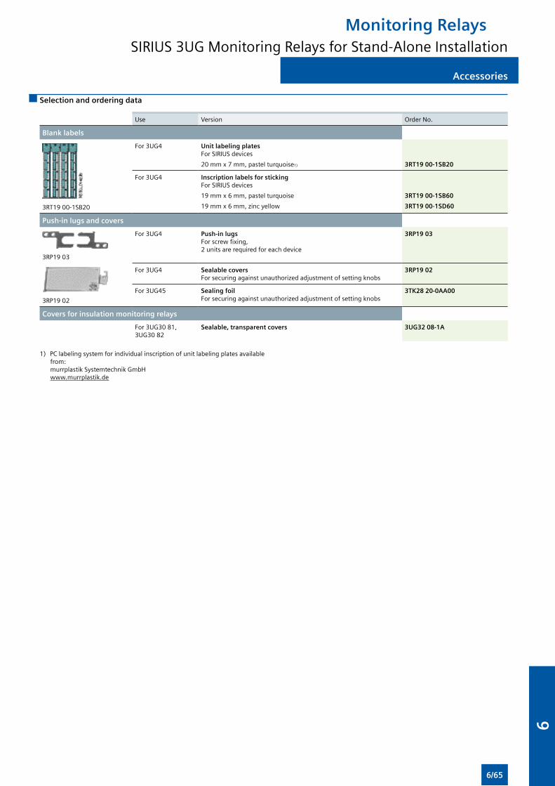
Accessories
Selection and ordering data
Use Version Order No.
Blank labels
3RT19 00-1SB20
For 3UG4 Unit labeling plates For SIRIUS devices
20 mm x 7 mm, pastel turquoise1)
3RT19 00-1SB20
For 3UG4 Inscription labels for sticking For SIRIUS devices
19 mm x 6 mm, pastel turquoise
19 mm x 6 mm, zinc yellow
3RT19 00-1SB60
3RT19 00-1SD60
Push-in lugs and covers
3RP19 03
For 3UG4 Push-in lugs For screw fixing, 2 units are required for each device
3RP19 03
3RP19 02
For 3UG4 Sealable covers For securing against unauthorized adjustment of setting knobs
3RP19 02
For 3UG45 Sealing foil For securing against unauthorized adjustment of setting knobs
3TK28 20-0AA00
Covers for insulation monitoring relays
For 3UG30 81, 3UG30 82
Sealable, transparent covers 3UG32 08-1A
1) PC labeling system for individual inscription of unit labeling plates available from: murrplastik Systemtechnik GmbH www.murrplastik.de
Monitoring RelaysSIRIUS 3UG Monitoring Relays for Stand-Alone Installation
6/65
6
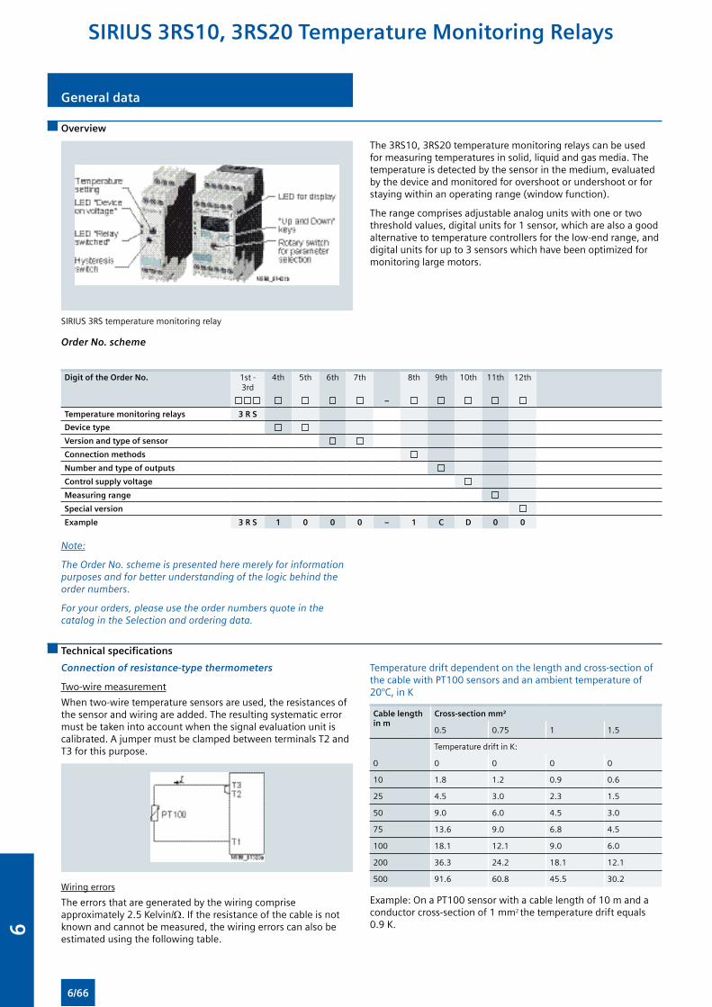
General data
Overview
SIRIUS 3RS temperature monitoring relay
The 3RS10, 3RS20 temperature monitoring relays can be used for measuring temperatures in solid, liquid and gas media. The temperature is detected by the sensor in the medium, evaluated by the device and monitored for overshoot or undershoot or for staying within an operating range (window function).
The range comprises adjustable analog units with one or two threshold values, digital units for 1 sensor, which are also a good alternative to temperature controllers for the low-end range, and digital units for up to 3 sensors which have been optimized for monitoring large motors.
Order No. scheme
Digit of the Order No. 1st - 3rd
4th 5th 6th 7th 8th 9th 10th 11th 12th
–
Temperature monitoring relays 3 R S
Device type
Version and type of sensor
Connection methods
Number and type of outputs
Control supply voltage
Measuring range
Special version
Example 3 R S 1 0 0 0 – 1 C D 0 0
Note:
The Order No. scheme is presented here merely for information purposes and for better understanding of the logic behind the order numbers.
For your orders, please use the order numbers quote in the catalog in the Selection and ordering data.
Technical specifications
Connection of resistance-type thermometers
Two-wire measurement
When two-wire temperature sensors are used, the resistances of the sensor and wiring are added. The resulting systematic error must be taken into account when the signal evaluation unit is calibrated. A jumper must be clamped between terminals T2 and T3 for this purpose.
Wiring errors
The errors that are generated by the wiring comprise approximately 2.5 Kelvin/Ω. If the resistance of the cable is not known and cannot be measured, the wiring errors can also be estimated using the following table.
Temperature drift dependent on the length and cross-section of the cable with PT100 sensors and an ambient temperature of 20°C, in K
Cable length in m
Cross-section mm²
0.5 0.75 1 1.5
Temperature drift in K:
0 0 0 0 0
10 1.8 1.2 0.9 0.6
25 4.5 3.0 2.3 1.5
50 9.0 6.0 4.5 3.0
75 13.6 9.0 6.8 4.5
100 18.1 12.1 9.0 6.0
200 36.3 24.2 18.1 12.1
500 91.6 60.8 45.5 30.2
Example: On a PT100 sensor with a cable length of 10 m and a conductor cross-section of 1 mm2 the temperature drift equals 0.9 K.
SIRIUS 3RS10, 3RS20 Temperature Monitoring Relays
6/66
6
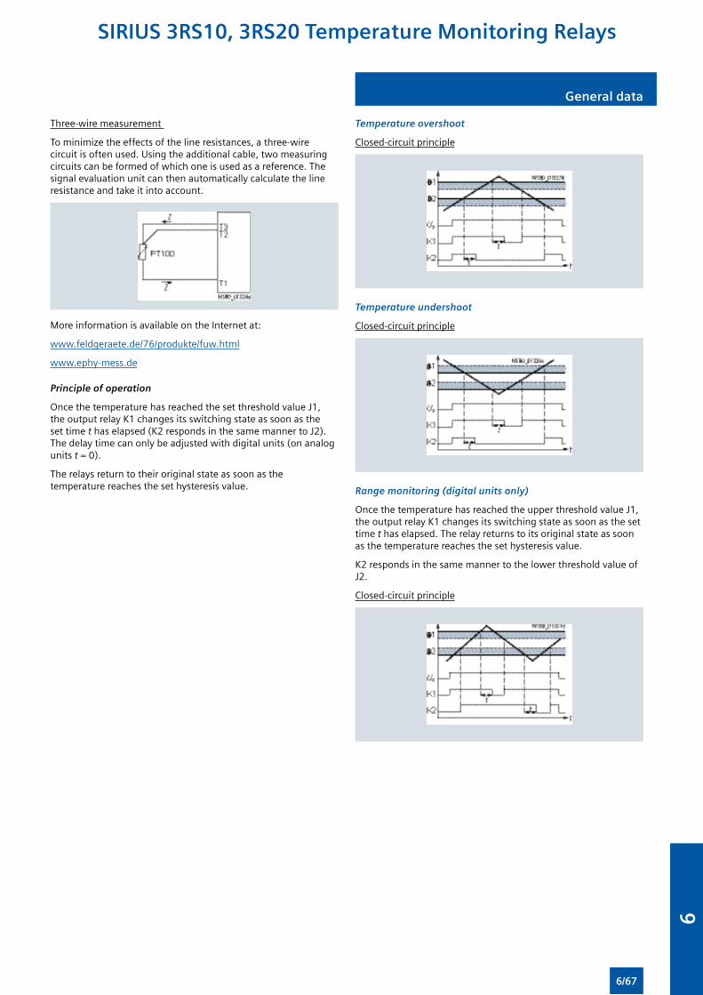
General data
Three-wire measurement
To minimize the effects of the line resistances, a three-wire circuit is often used. Using the additional cable, two measuring circuits can be formed of which one is used as a reference. The signal evaluation unit can then automatically calculate the line resistance and take it into account.
More information is available on the Internet at:
www.feldgeraete.de/76/produkte/fuw.html
www.ephy-mess.de
Principle of operation
Once the temperature has reached the set threshold value J1, the output relay K1 changes its switching state as soon as the set time t has elapsed (K2 responds in the same manner to J2). The delay time can only be adjusted with digital units (on analog units t = 0).
The relays return to their original state as soon as the temperature reaches the set hysteresis value.
Temperature overshoot
Closed-circuit principle
Temperature undershoot
Closed-circuit principle
Range monitoring (digital units only)
Once the temperature has reached the upper threshold value J1, the output relay K1 changes its switching state as soon as the set time t has elapsed. The relay returns to its original state as soon as the temperature reaches the set hysteresis value.
K2 responds in the same manner to the lower threshold value of J2.
Closed-circuit principle
SIRIUS 3RS10, 3RS20 Temperature Monitoring Relays
6/67
6
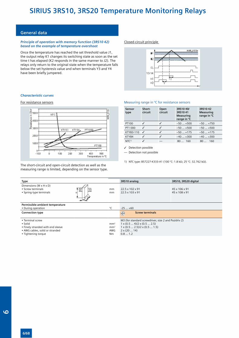
General data
Principle of operation with memory function (3RS10 42) based on the example of temperature overshoot
Once the temperature has reached the set threshold value J1, the output relay K1 changes its switching state as soon as the set time t has elapsed (K2 responds in the same manner to J2). The relays only return to the original state when the temperature falls below the set hysteresis value and when terminals Y3 and Y4 have been briefly jumpered.
Closed-circuit principle
Characteristic curves
For resistance sensors
The short-circuit and open-circuit detection as well as the measuring range is limited, depending on the sensor type.
Measuring range in °C for resistance sensors
Sensor type
Short-circuit
Open circuit
3RS10 40/ 3RS10 41 Measuring range in °C
3RS10 42 Measuring range in °C
PT100 3 3 –50 ... +500 –50 ... +750
PT1 000 3 3 –50 ... +500 –50 ... +500
KTY83-110 3 3 –50 ... +175 –50 ... +175
KTY84 3 3 –40 ... +300 –40 ... +300
NTC1) 3 — 80 ... 160 80 ... 160
3 Detection possible
— Detection not possible
1) NTC type: B57227-K333-A1 (100 °C: 1.8 kΩ; 25 °C: 32.762 kΩ).
Type 3RS10 analog 3RS10, 3RS20 digital
Dimensions (W x H x D) • Screw terminals• Spring-type terminals
mmmm
22.5 x 102 x 9122.5 x 103 x 91
45 x 106 x 9145 x 108 x 91
Permissible ambient temperature• During operation °C -25 ... +60
Connection type Screw terminals
• Terminal screw• Solid• Finely stranded with end sleeve• AWG cables, solid or stranded• Tightening torque
mm2
mm2
AWGNm
M3 (for standard screwdriver, size 2 and Pozidriv 2)1 x (0.5 ... 4)/2 x (0.5 ... 2.5)1 x (0.5 ... 2.5)/2 x (0.5 ... 1.5)2 x (20 ... 14)0.8 … 1.2
SIRIUS 3RS10, 3RS20 Temperature Monitoring Relays
6/68
6
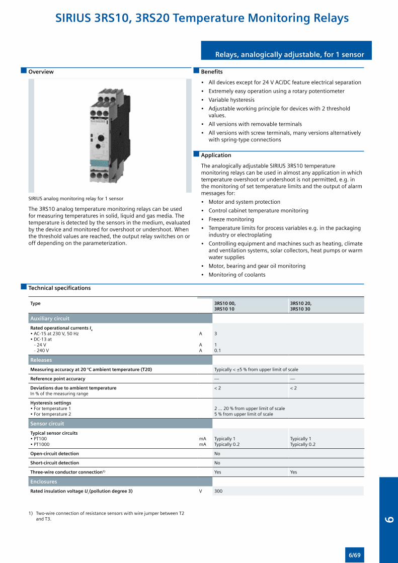
Relays, analogically adjustable, for 1 sensor
Overview
SIRIUS analog monitoring relay for 1 sensor
The 3RS10 analog temperature monitoring relays can be used for measuring temperatures in solid, liquid and gas media. The temperature is detected by the sensors in the medium, evaluated by the device and monitored for overshoot or undershoot. When the threshold values are reached, the output relay switches on or off depending on the parameterization.
Benefits
• All devices except for 24 V AC/DC feature electrical separation
• Extremely easy operation using a rotary potentiometer
• Variable hysteresis
• Adjustable working principle for devices with 2 threshold values.
• All versions with removable terminals
• All versions with screw terminals, many versions alternatively with spring-type connections
Application
The analogically adjustable SIRIUS 3RS10 temperature monitoring relays can be used in almost any application in which temperature overshoot or undershoot is not permitted, e.g. in the monitoring of set temperature limits and the output of alarm messages for:
• Motor and system protection
• Control cabinet temperature monitoring
• Freeze monitoring
• Temperature limits for process variables e.g. in the packaging industry or electroplating
• Controlling equipment and machines such as heating, climate and ventilation systems, solar collectors, heat pumps or warm water supplies
• Motor, bearing and gear oil monitoring
• Monitoring of coolants
Technical specifications
Type 3RS10 00, 3RS10 10
3RS10 20, 3RS10 30
Auxiliary circuit
Rated operational currents Ie • AC-15 at 230 V, 50 Hz• DC-13 at - 24 V - 240 V
A AA
3 10.1
Releases
Measuring accuracy at 20 °C ambient temperature (T20) Typically < ±5 % from upper limit of scale
Reference point accuracy — —
Deviations due to ambient temperatureIn % of the measuring range
< 2 < 2
Hysteresis settings • For temperature 1• For temperature 2
2 ... 20 % from upper limit of scale5 % from upper limit of scale
Sensor circuit
Typical sensor circuits • PT100• PT1000
mAmA
Typically 1Typically 0.2
Typically 1Typically 0.2
Open-circuit detection No
Short-circuit detection No
Three-wire conductor connection1) Yes Yes
Enclosures
Rated insulation voltage Ui (pollution degree 3) V 300
1) Two-wire connection of resistance sensors with wire jumper between T2 and T3.
SIRIUS 3RS10, 3RS20 Temperature Monitoring Relays
6/69
6
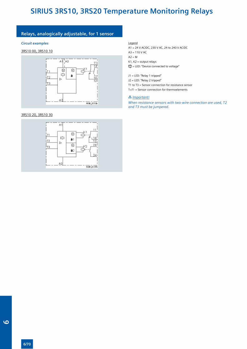
Relays, analogically adjustable, for 1 sensor
Circuit examples
3RS10 00, 3RS10 10
3RS10 20, 3RS10 30
Legend
A1 = 24 V AC/DC, 230 V AC, 24 to 240 V AC/DC
A3 = 110 V AC
A2 = M
K1, K2 = output relays
= LED: “Device connected to voltage”
J1 = LED: “Relay 1 tripped”
J2 = LED: “Relay 2 tripped”
T1 to T3 = Sensor connection for resistance sensor
T+/T- = Sensor connection for thermoelements
Important!
When resistance sensors with two-wire connection are used, T2 and T3 must be jumpered.
SIRIUS 3RS10, 3RS20 Temperature Monitoring Relays
6/70
6
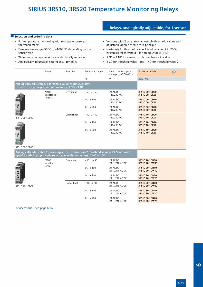
Relays, analogically adjustable, for 1 sensor
Selection and ordering data
• For temperature monitoring with resistance sensors or thermoelements
• Temperature range -55 °C to +1000 °C, depending on the sensor type
• Wide-range voltage versions are electrically separated.
• Analogically adjustable, setting accuracy ±5 %
• Versions with 2 separately adjustable threshold values and adjustable open/closed-circuit principle
• Hysteresis for threshold value 1 is adjustable (2 to 20 %), hysteresis for threshold 2 is non-adjustable (5 %)
• 1 NC + 1 NO for versions with one threshold value
• 1 CO for threshold value1 and 1 NO for threshold value 2
Sensor Function Measuring range Rated control supply voltage Us AC 50/60 Hz
Screw terminals
°C V Order No.
Analogically adjustable, 1 threshold value, width 22,5 mm; closed-circuit principle; without memory; 1 NO + 1 NC
3RS10 00-1CD10
3RS10 00-2CD10
PT100 (resistance sensor)
Overshoot - 50 … + 50 24 AC/DC110/230 AC
3RS10 00-1CD003RS10 00-1CK00
0 … + 100 24 AC/DC110/230 AC
3RS10 00-1CD103RS10 00-1CK10
0 … + 200 24 AC/DC110/230 AC
3RS10 00-1CD203RS10 00-1CK20
Undershoot - 50 … + 50 24 AC/DC110/230 AC
3RS10 10-1CD003RS10 10-1CK00
0 … + 100 24 AC/DC110/230 AC
3RS10 10-1CD103RS10 10-1CK10
0 … + 200 24 AC/DC110/230 AC
3RS10 10-1CD203RS10 10-1CK20
Analogically adjustable for warning and disconnection (2 threshold values), 22.5 mm width, open/closed-circuit principle switchable; without memory; 1 NO + 1 CO
3RS10 20-1DD00
PT100 (resistance sensor)
Overshoot - 50 … + 50 24 AC/DC24 … 240 AC/DC
3RS10 20-1DD003RS10 20-1DW00
0 … + 100 24 AC/DC24 … 240 AC/DC
3RS10 20-1DD103RS10 20-1DW10
0 … + 200 24 AC/DC24 … 240 AC/DC
3RS10 20-1DD203RS10 20-1DW20
Undershoot -50 … + 50 24 AC/DC24 … 240 AC/DC
3RS10 30-1DD003RS10 30-1DW00
0 … + 100 24 AC/DC24 … 240 AC/DC
3RS10 30-1DD103RS10 30-1DW10
0 … + 200 24 AC/DC24 … 240 AC/DC
3RS10 30-1DD203RS10 30-1DW20
For accessories, see page 6/76.
SIRIUS 3RS10, 3RS20 Temperature Monitoring Relays
6/71
6
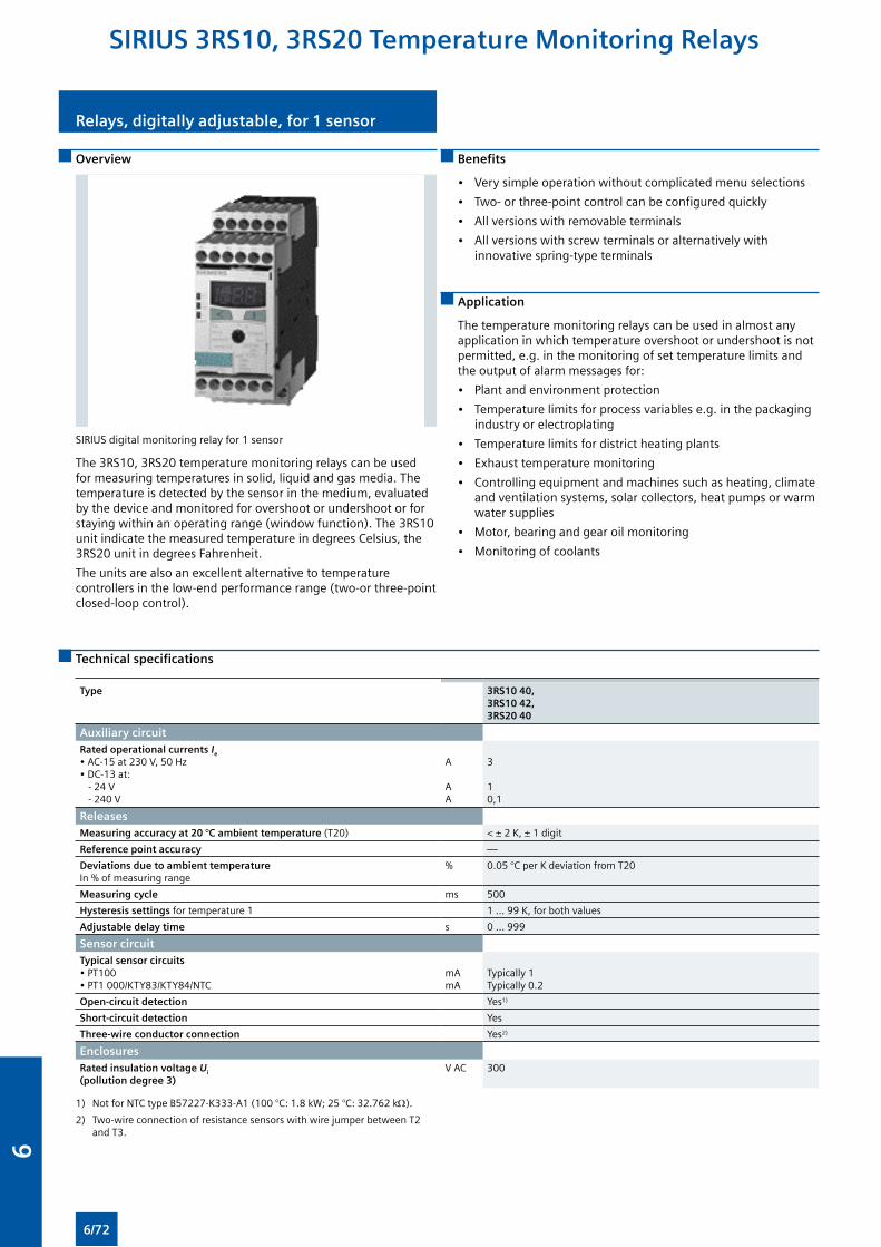
Overview
SIRIUS digital monitoring relay for 1 sensor
The 3RS10, 3RS20 temperature monitoring relays can be used for measuring temperatures in solid, liquid and gas media. The temperature is detected by the sensor in the medium, evaluated by the device and monitored for overshoot or undershoot or for staying within an operating range (window function). The 3RS10 unit indicate the measured temperature in degrees Celsius, the 3RS20 unit in degrees Fahrenheit.
The units are also an excellent alternative to temperature controllers in the low-end performance range (two-or three-point closed-loop control).
Benefits
• Very simple operation without complicated menu selections
• Two- or three-point control can be configured quickly
• All versions with removable terminals
• All versions with screw terminals or alternatively with innovative spring-type terminals
Application
The temperature monitoring relays can be used in almost any application in which temperature overshoot or undershoot is not permitted, e.g. in the monitoring of set temperature limits and the output of alarm messages for:
• Plant and environment protection
• Temperature limits for process variables e.g. in the packaging industry or electroplating
• Temperature limits for district heating plants
• Exhaust temperature monitoring
• Controlling equipment and machines such as heating, climate and ventilation systems, solar collectors, heat pumps or warm water supplies
• Motor, bearing and gear oil monitoring
• Monitoring of coolants
Technical specifications
Type 3RS10 40, 3RS10 42, 3RS20 40
Auxiliary circuit
Rated operational currents Ie
• AC-15 at 230 V, 50 Hz• DC-13 at: - 24 V - 240 V
A AA
3 10,1
Releases
Measuring accuracy at 20 °C ambient temperature (T20) < ± 2 K, ± 1 digit
Reference point accuracy —
Deviations due to ambient temperature In % of measuring range
% 0.05 °C per K deviation from T20
Measuring cycle ms 500
Hysteresis settings for temperature 1 1 ... 99 K, for both values
Adjustable delay time s 0 ... 999
Sensor circuit
Typical sensor circuits • PT100• PT1 000/KTY83/KTY84/NTC
mAmA
Typically 1Typically 0.2
Open-circuit detection Yes1)
Short-circuit detection Yes
Three-wire conductor connection Yes2)
Enclosures
Rated insulation voltage Ui
(pollution degree 3) V AC 300
1) Not for NTC type B57227-K333-A1 (100 °C: 1.8 kW; 25 °C: 32.762 kΩ).
2) Two-wire connection of resistance sensors with wire jumper between T2 and T3.
Relays, digitally adjustable, for 1 sensor
SIRIUS 3RS10, 3RS20 Temperature Monitoring Relays
6/72
6
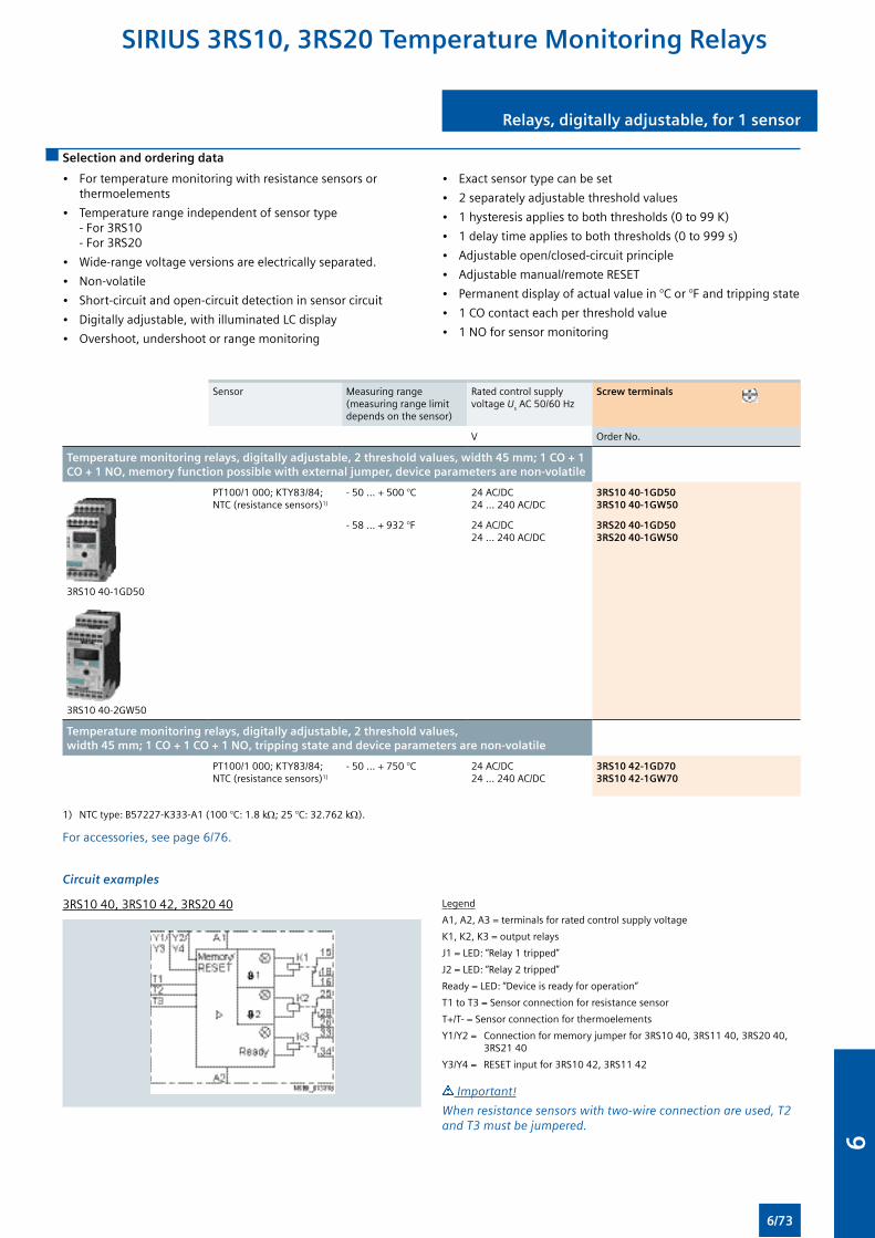
Relays, digitally adjustable, for 1 sensor
Selection and ordering data
• For temperature monitoring with resistance sensors or thermoelements
• Temperature range independent of sensor type - For 3RS10 - For 3RS20
• Wide-range voltage versions are electrically separated.
• Non-volatile
• Short-circuit and open-circuit detection in sensor circuit
• Digitally adjustable, with illuminated LC display
• Overshoot, undershoot or range monitoring
• Exact sensor type can be set
• 2 separately adjustable threshold values
• 1 hysteresis applies to both thresholds (0 to 99 K)
• 1 delay time applies to both thresholds (0 to 999 s)
• Adjustable open/closed-circuit principle
• Adjustable manual/remote RESET
• Permanent display of actual value in °C or °F and tripping state
• 1 CO contact each per threshold value
• 1 NO for sensor monitoring
Sensor Measuring range (measuring range limit depends on the sensor)
Rated control supply voltage Us AC 50/60 Hz
Screw terminals
V Order No.
Temperature monitoring relays, digitally adjustable, 2 threshold values, width 45 mm; 1 CO + 1 CO + 1 NO, memory function possible with external jumper, device parameters are non-volatile
3RS10 40-1GD50
3RS10 40-2GW50
PT100/1 000; KTY83/84; NTC (resistance sensors)1)
- 50 … + 500 °C 24 AC/DC24 … 240 AC/DC
3RS10 40-1GD503RS10 40-1GW50
- 58 … + 932 °F 24 AC/DC24 … 240 AC/DC
3RS20 40-1GD503RS20 40-1GW50
Temperature monitoring relays, digitally adjustable, 2 threshold values, width 45 mm; 1 CO + 1 CO + 1 NO, tripping state and device parameters are non-volatile
PT100/1 000; KTY83/84; NTC (resistance sensors)1)
- 50 … + 750 °C 24 AC/DC24 … 240 AC/DC
3RS10 42-1GD703RS10 42-1GW70
1) NTC type: B57227-K333-A1 (100 °C: 1.8 kΩ; 25 °C: 32.762 kΩ).
For accessories, see page 6/76.
Circuit examples
3RS10 40, 3RS10 42, 3RS20 40 Legend
A1, A2, A3 = terminals for rated control supply voltage
K1, K2, K3 = output relays
J1 = LED: “Relay 1 tripped”
J2 = LED: “Relay 2 tripped”
Ready = LED: “Device is ready for operation”
T1 to T3 = Sensor connection for resistance sensor
T+/T- = Sensor connection for thermoelements
Y1/Y2 = Connection for memory jumper for 3RS10 40, 3RS11 40, 3RS20 40, 3RS21 40
Y3/Y4 = RESET input for 3RS10 42, 3RS11 42
Important!
When resistance sensors with two-wire connection are used, T2 and T3 must be jumpered.
SIRIUS 3RS10, 3RS20 Temperature Monitoring Relays
6/73
6
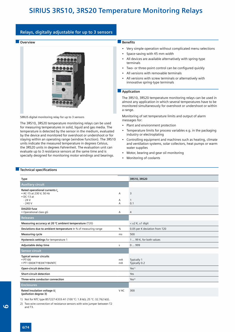
Relays, digitally adjustable for up to 3 sensors
Overview
SIRIUS digital monitoring relay for up to 3 sensors
The 3RS10, 3RS20 temperature monitoring relays can be used for measuring temperatures in solid, liquid and gas media. The temperature is detected by the sensor in the medium, evaluated by the device and monitored for overshoot or undershoot or for staying within an operating range (window function). The 3RS10 units indicate the measured temperature in degrees Celsius, the 3RS20 units in degrees Fahrenheit. The evaluation unit can evaluate up to 3 resistance sensors at the same time and is specially designed for monitoring motor windings and bearings.
Benefits
• Very simple operation without complicated menu selections
• Space-saving with 45 mm width
• All devices are available alternatively with spring-type terminals
• Two- or three-point control can be configured quickly
• All versions with removable terminals
• All versions with screw terminals or alternatively with innovative spring-type terminals
Application
The 3RS10, 3RS20 temperature monitoring relays can be used in almost any application in which several temperatures have to be monitored simultaneously for overshoot or undershoot or within a range.
Monitoring of set temperature limits and output of alarm messages for:
• Plant and environment protection
• Temperature limits for process variables e.g. in the packaging industry or electroplating
• Controlling equipment and machines such as heating, climate and ventilation systems, solar collectors, heat pumps or warm water supplies
• Motor, bearing and gear oil monitoring
• Monitoring of coolants
Technical specifications
Type 3RS10, 3RS20
Auxiliary circuit
Rated operational currents Ie • AC-15 at 230 V, 50 Hz• DC-13 at - 24 V - 240 V
A AA
3 10.1
DIAZED fuse • Operational class gG
A
4
Releases
Measuring accuracy at 20 °C ambient temperature (T20) < ±2 K, ±1 digit
Deviations due to ambient temperature In % of measuring range % 0.05 per K deviation from T20
Measuring cycle ms 500
Hysteresis settings for temperature 1 1 ... 99 K, for both values
Adjustable delay time s 0 ... 999
Sensor circuit
Typical sensor circuits • PT100• PT1 000/KTY83/KTY84/NTC
mAmA
Typically 1Typically 0.2
Open-circuit detection Yes1)
Short-circuit detection Yes
Three-wire conductor connection Yes2)
Enclosures
Rated insulation voltage Ui
(pollution degree 3) V AC 300
1) Not for NTC type B57227-K333-A1 (100 °C: 1.8 kΩ; 25 °C: 32.762 kΩ).
2) Two-wire connection of resistance sensors with wire jumper between T2 and T3.
SIRIUS 3RS10, 3RS20 Temperature Monitoring Relays
6/74
6
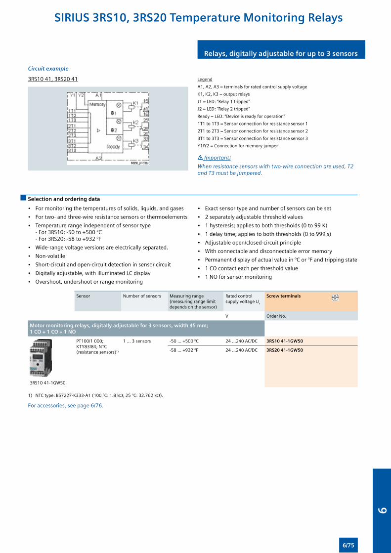
Relays, digitally adjustable for up to 3 sensors
Circuit example
3RS10 41, 3RS20 41 Legend
A1, A2, A3 = terminals for rated control supply voltage
K1, K2, K3 = output relays
J1 = LED: “Relay 1 tripped”
J2 = LED: “Relay 2 tripped”
Ready = LED: “Device is ready for operation”
1T1 to 1T3 = Sensor connection for resistance sensor 1
2T1 to 2T3 = Sensor connection for resistance sensor 2
3T1 to 3T3 = Sensor connection for resistance sensor 3
Y1/Y2 = Connection for memory jumper
Important!
When resistance sensors with two-wire connection are used, T2 and T3 must be jumpered.
Selection and ordering data
• For monitoring the temperatures of solids, liquids, and gases
• For two- and three-wire resistance sensors or thermoelements
• Temperature range independent of sensor type - For 3RS10: -50 to +500 °C - For 3RS20: -58 to +932 °F
• Wide-range voltage versions are electrically separated.
• Non-volatile
• Short-circuit and open-circuit detection in sensor circuit
• Digitally adjustable, with illuminated LC display
• Overshoot, undershoot or range monitoring
• Exact sensor type and number of sensors can be set
• 2 separately adjustable threshold values
• 1 hysteresis; applies to both thresholds (0 to 99 K)
• 1 delay time; applies to both thresholds (0 to 999 s)
• Adjustable open/closed-circuit principle
• With connectable and disconnectable error memory
• Permanent display of actual value in °C or °F and tripping state
• 1 CO contact each per threshold value
• 1 NO for sensor monitoring
Sensor Number of sensors Measuring range (measuring range limit depends on the sensor)
Rated control supply voltage Us
Screw terminals
V Order No.
Motor monitoring relays, digitally adjustable for 3 sensors, width 45 mm; 1 CO + 1 CO + 1 NO
3RS10 41-1GW50
PT100/1 000; KTY83/84; NTC (resistance sensors)1)
1 ... 3 sensors -50 ... +500 °C 24 ...240 AC/DC 3RS10 41-1GW50
-58 ... +932 °F 24 ...240 AC/DC 3RS20 41-1GW50
1) NTC type: B57227-K333-A1 (100 °C: 1.8 kΩ; 25 °C: 32.762 kΩ).
For accessories, see page 6/76.
SIRIUS 3RS10, 3RS20 Temperature Monitoring Relays
6/75
6
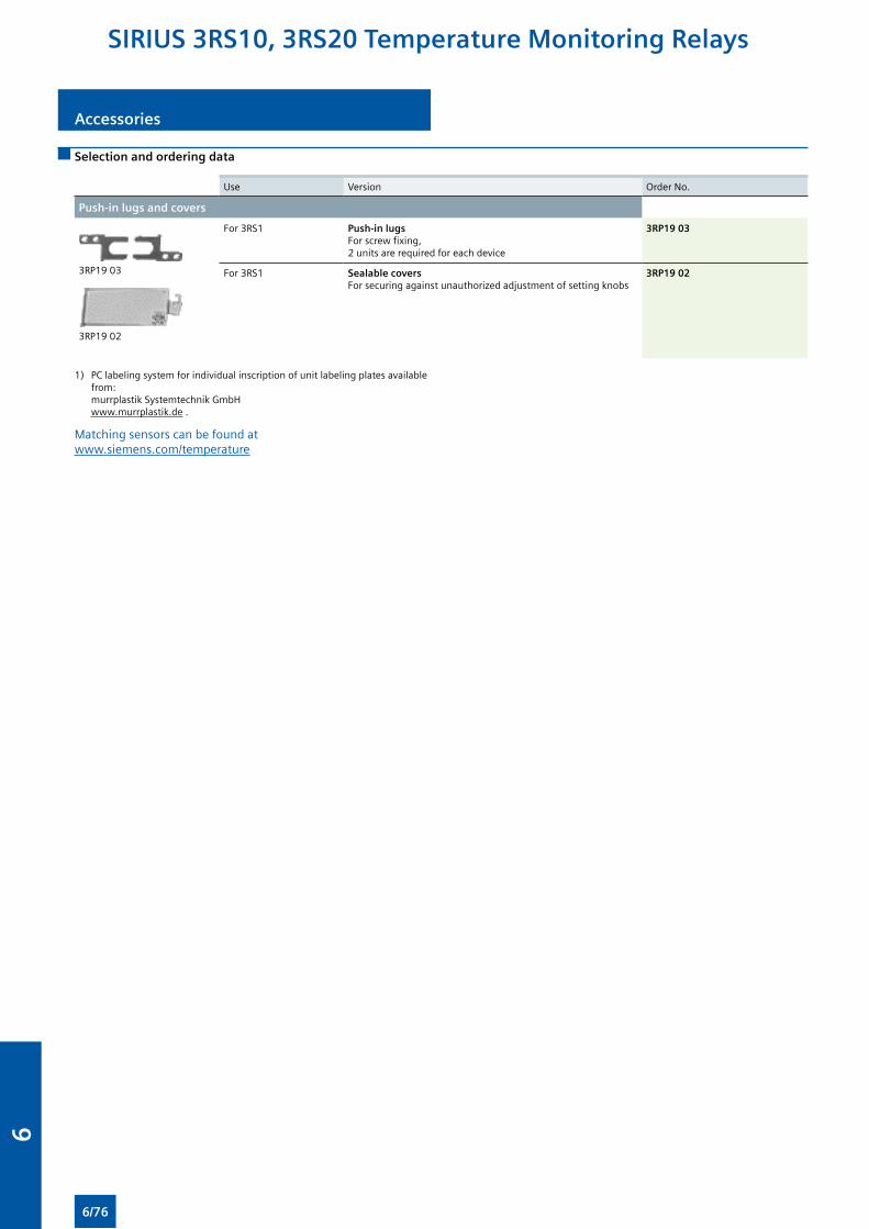
Accessories
Selection and ordering data
Use Version Order No.
Push-in lugs and covers
3RP19 03
3RP19 02
For 3RS1 Push-in lugs For screw fixing,2 units are required for each device
3RP19 03
For 3RS1 Sealable covers For securing against unauthorized adjustment of setting knobs
3RP19 02
1) PC labeling system for individual inscription of unit labeling plates available from: murrplastik Systemtechnik GmbH www.murrplastik.de .
Matching sensors can be found at www.siemens.com/temperature
SIRIUS 3RS10, 3RS20 Temperature Monitoring Relays
6/76
6
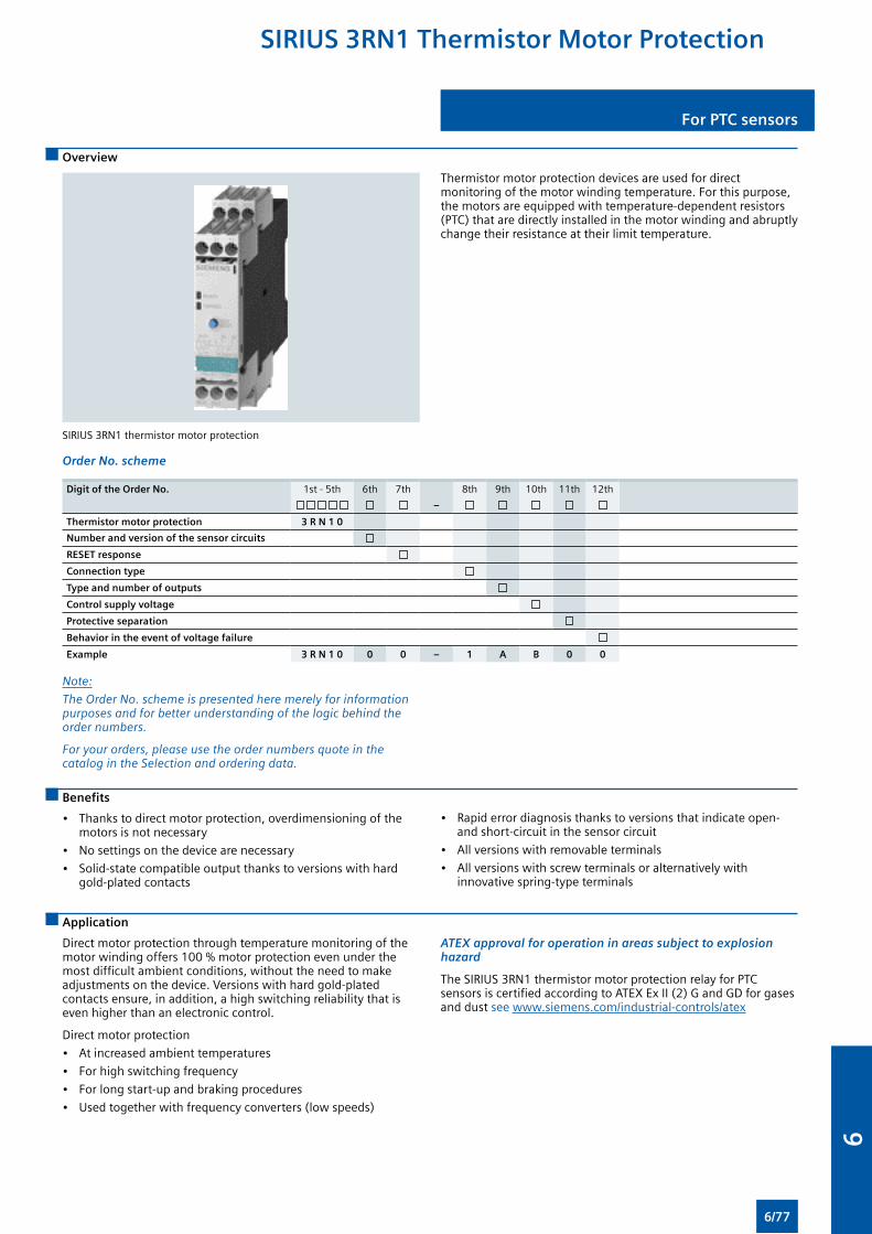
For PTC sensors
Overview
SIRIUS 3RN1 thermistor motor protection
Thermistor motor protection devices are used for direct monitoring of the motor winding temperature. For this purpose, the motors are equipped with temperature-dependent resistors (PTC) that are directly installed in the motor winding and abruptly change their resistance at their limit temperature.
Order No. scheme
Digit of the Order No. 1st - 5th 6th 7th 8th 9th 10th 11th 12th
–
Thermistor motor protection 3 R N 1 0
Number and version of the sensor circuits
RESET response
Connection type
Type and number of outputs
Control supply voltage
Protective separation
Behavior in the event of voltage failure
Example 3 R N 1 0 0 0 – 1 A B 0 0
Note:
The Order No. scheme is presented here merely for information purposes and for better understanding of the logic behind the order numbers.
For your orders, please use the order numbers quote in the catalog in the Selection and ordering data.
Benefits
• Thanks to direct motor protection, overdimensioning of the motors is not necessary
• No settings on the device are necessary
• Solid-state compatible output thanks to versions with hard gold-plated contacts
• Rapid error diagnosis thanks to versions that indicate open- and short-circuit in the sensor circuit
• All versions with removable terminals
• All versions with screw terminals or alternatively with innovative spring-type terminals
Application
Direct motor protection through temperature monitoring of the motor winding offers 100 % motor protection even under the most difficult ambient conditions, without the need to make adjustments on the device. Versions with hard gold-plated contacts ensure, in addition, a high switching reliability that is even higher than an electronic control.
Direct motor protection
• At increased ambient temperatures
• For high switching frequency
• For long start-up and braking procedures
• Used together with frequency converters (low speeds)
ATEX approval for operation in areas subject to explosion hazard
The SIRIUS 3RN1 thermistor motor protection relay for PTC sensors is certified according to ATEX Ex II (2) G and GD for gases and dust see www.siemens.com/industrial-controls/atex
SIRIUS 3RN1 Thermistor Motor Protection
6/77
6
For PTC sensors
Use in areas subject to explosion hazard for gases
All devices are approved for Equipment Group II, Category (2) in Area “G” (areas that contain explosive gases, vapor, spray and air mixtures).
With PTB 01 ATEX 3218 ex II (2) G, compliance with directive 94/9 EC Appendix II is confirmed. The safety devices must be selected with suitable settings for the safe operation of motors of the “Increased safety” (EEx e) and “Flameproof enclosure” (EEx d) degrees of protection and are used outside the area subject to explosion hazard.
PTB 01 ATEX 3218 ex II (2) G
The increased danger in areas subject to explosion hazard demands careful analysis of the operator’s guide, the safety and commissioning instructions and the standard (EN 60079-14 / VDE 0165) for electronic equipment in areas subject to gas explosion hazards.
A risk analysis must be performed for the complete plant or machine. If this risk analysis results in a minimal potential for danger (Safety Category 1), all 3RN1 TMS releases can be implemented taking into account the safety notes. In the case of plants or machines with a high potential risk, versions with integrated short-circuit detection in the sensor circuit are necessary.
Device Class
3RN10 00 EN 954-1: Category 1
The measuring circuit leads must be routed as separate control cables. It is not permitted to use cores from the supply line of the motor or any other main supply cables. If extreme inductive or capacitive interference is expected as a result of power lines routed in parallel, shielded control cables must be used.
Cable routing
Maximum cable length for sensor circuit cables
Conductor cross section Cable length for releases
Without short-circuit detection 3RN10 00
mm2 m
2.5 2 x 2 800
1.5 2 x 1 500
0.5 2 x 500
1) A short-circuit in the sensor circuit will be detected up to this maximum cable length.
Note:
Tripping of the thermistor motor protection relay even in combination with a converter must directly result in disconnection. This must be implemented with circuitry.
Mounting and installation must only be performed by qualified personnel who observe the applicable regulations! For mounting, use the mounting instructions Order No.: 3ZX1012-0RN10-1AA1.
The 3RN10 is not intended for installation in hazardous areas. For installation in areas subject to explosion hazards, the 3RN10 must be enclosed in a flameproof casing.
For tripping units with a 24 V AC/DC control voltage, electrical separation must be secured with a battery network or a safety transformer to EN 61558.
When releases with Auto-RESET function are used, a reset is performed automatically after the cooling time has expired. It must be ensured by means of an external interlock (latching with a separate ON and OFF button) that the machine to be monitored does not start up again spontaneously.
Units with the “Auto-RESET” function must not be used in applications in which the unexpected restart can lead to personal injury or property damage.
In the case of releases without short-circuit detection, during commissioning or after modifications or maintenance work (assembly, disassembly) on the equipment, the sensor resistance must be measured using a suitable measuring device. For resistances of < 50 W the sensor circuit must be checked for a short-circuit.
If 3RN10 00 units are used to protect EEx e motors, separate monitoring of the control voltage is recommended because there is no Ready LED to indicate connection to the supply voltage.
Before commissioning, the effectiveness of the protection function must be checked.
SIRIUS 3RN1 Thermistor Motor Protection
6/78
6
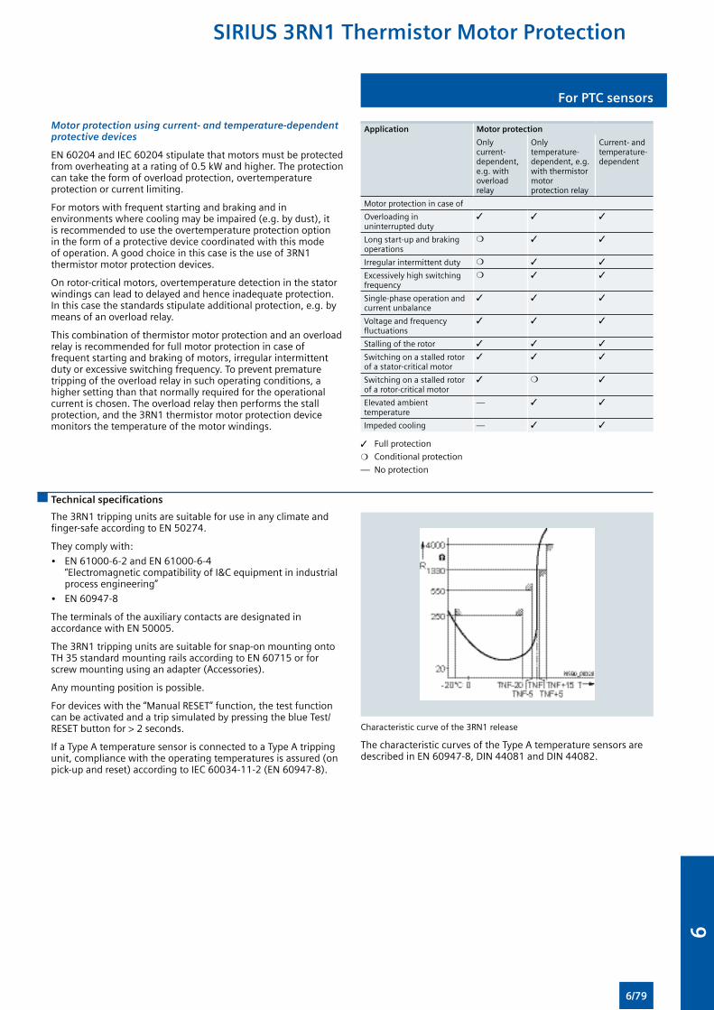
For PTC sensors
Motor protection using current- and temperature-dependent protective devices
EN 60204 and IEC 60204 stipulate that motors must be protected from overheating at a rating of 0.5 kW and higher. The protection can take the form of overload protection, overtemperature protection or current limiting.
For motors with frequent starting and braking and in environments where cooling may be impaired (e.g. by dust), it is recommended to use the overtemperature protection option in the form of a protective device coordinated with this mode of operation. A good choice in this case is the use of 3RN1 thermistor motor protection devices.
On rotor-critical motors, overtemperature detection in the stator windings can lead to delayed and hence inadequate protection. In this case the standards stipulate additional protection, e.g. by means of an overload relay.
This combination of thermistor motor protection and an overload relay is recommended for full motor protection in case of frequent starting and braking of motors, irregular intermittent duty or excessive switching frequency. To prevent premature tripping of the overload relay in such operating conditions, a higher setting than that normally required for the operational current is chosen. The overload relay then performs the stall protection, and the 3RN1 thermistor motor protection device monitors the temperature of the motor windings.
Application Motor protection
Only current-dependent, e.g. with overload relay
Only temperature-dependent, e.g. with thermistor motor protection relay
Current- and temperature-dependent
Motor protection in case of
Overloading in uninterrupted duty
3 3 3
Long start-up and braking operations
m 3 3
Irregular intermittent duty m 3 3
Excessively high switching frequency
m 3 3
Single-phase operation and current unbalance
3 3 3
Voltage and frequency fluctuations
3 3 3
Stalling of the rotor 3 3 3
Switching on a stalled rotor of a stator-critical motor
3 3 3
Switching on a stalled rotor of a rotor-critical motor
3 m 3
Elevated ambient temperature
— 3 3
Impeded cooling — 3 3
3 Full protection
m Conditional protection
— No protection
Technical specifications
The 3RN1 tripping units are suitable for use in any climate and finger-safe according to EN 50274.
They comply with:
• EN 61000-6-2 and EN 61000-6-4 “Electromagnetic compatibility of I&C equipment in industrial process engineering”
• EN 60947-8
The terminals of the auxiliary contacts are designated in accordance with EN 50005.
The 3RN1 tripping units are suitable for snap-on mounting onto TH 35 standard mounting rails according to EN 60715 or for screw mounting using an adapter (Accessories).
Any mounting position is possible.
For devices with the “Manual RESET” function, the test function can be activated and a trip simulated by pressing the blue Test/RESET button for > 2 seconds.
If a Type A temperature sensor is connected to a Type A tripping unit, compliance with the operating temperatures is assured (on pick-up and reset) according to IEC 60034-11-2 (EN 60947-8).
Characteristic curve of the 3RN1 release
The characteristic curves of the Type A temperature sensors are described in EN 60947-8, DIN 44081 and DIN 44082.
SIRIUS 3RN1 Thermistor Motor Protection
6/79
6
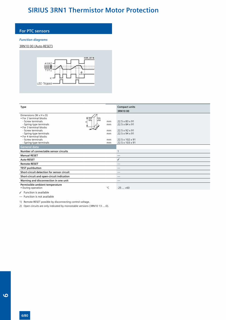
For PTC sensors
Function diagrams
3RN10 00 (Auto-RESET)
Type Compact units
3RN10 00
Dimensions (W x H x D) • For 2 terminal blocks - Screw terminals - Spring-type terminals• For 3 terminal blocks - Screw terminals - Spring-type terminals• For 4 terminal blocks - Screw terminals - Spring-type terminals
mmmm
mmmm
mmmm
22.5 x 83 x 9122.5 x 84 x 91
22.5 x 92 x 9122.5 x 94 x 91
22.5 x 102 x 9122.5 x 103 x 91
General dataNumber of connectable sensor circuits 1
Manual RESET —
Auto-RESET 3
Remote-RESET —
TEST pushbutton —
Short-circuit detection for sensor circuit —
Short-circuit and open-circuit indication —
Warning and disconnection in one unit —
Permissible ambient temperature• During operation °C -25 ... +60
3 Function is available
— Function is not available
1) Remote-RESET possible by disconnecting control voltage.
2) Open circuits are only indicated by monostable versions (3RN10 13-....0).
SIRIUS 3RN1 Thermistor Motor Protection
6/80
6
For PTC sensors
Principle of operation
The 3RN1 releases operate in accordance with the closed-circuit principle and therefore monitor themselves for open circuit. A momentary voltage failure of less than 50 ms does not change the status of the auxiliary contacts.
All tripping units (except for 24 V AC/DC) feature electrical separation between the control circuit and the sensor circuit.
3RN10 00 compact releases
The compact release is equipped with a red LED (TRIPPED) for the tripped indicator and a changeover contact.
After the unit has tripped, it is automatically reset once the thermistors have cooled down. The root of the changeover contact is connected to the control voltage (95 is connected to terminal A1).
This unit is particularly suitable in circuits in which the control circuit and signaling circuit have the same potential, e.g. in local control cabinets.
Response of the releases in the event of control voltage failure
Behavior Monostable
3RN10 00, 3RN10 10, 3RN10 11
In case of failure of the control voltage Device trips
In case of return of the control voltage without a preceding tripping operation
Device resets
In case of return of the control voltage after a preceding tripping operation
Device resets
SIRIUS 3RN1 Thermistor Motor Protection
6/81
6
For PTC sensors
Type Compact units
3RN10 00
Releases
Rated insulation voltage Ui (pollution degree 3) V 300
Connection type Screw terminals
• Terminal screw• Solid• Finely stranded with end sleeve• AWG cables, solid or stranded• Tightening torque
mm2
mm2
AWGNm
M3 (for standard screwdriver, size 2 and Pozidriv 2)1 x (0.5 ... 4)/2 x (0.5 ... 2.5)1 x (0.5 ... 2.5)/2 x (0.5 ... 1.5)2 x (20 ... 14)0.8 … 1.2
Sensor circuit
Measuring circuit load at RF ≤ 1.5 mW ≤ 5
Voltage in sensor circuit at RF ≤ 1.5 mW V ≤ 2
Response temperature (depends on sensor) °C 60 ... 180
Coupling time (depends on sensor) s About 5
Summation PTC resistance RF (per sensor loop) kΩ ≤ 1.5; response value 3.4 ... 3.8; return value 1.5 ... 1.65
Response tolerance °C ±6
Control circuit
Rated control supply voltage Us See page 6/84
Operating range • 110/230 V AC• 24 ... 240 V AC/DC• 24 V AC/DC
0,85 ... 1.1 x Us
0,85 ... 1.1 x Us
0.85 ... 1.2 x Us for DC operation, 0.85 ... 1.1 x Us for AC operation
Rated power AC/DC W < 2
Auxiliary circuit
Conventional thermal current Ith A 5
Rated operational current Ie
• AC-15/240 V• DC-13/24 V
AA
31
DIAZED fuse A 61)
CSA and UL rated data, control circuit
Rated control voltage 50/60 Hz• AC• DC
VV
300300
Switching capacity R 300/B 300
Protective separation up to 300 V according to DIN 60947-1
—
1) In > 1 kA weld-free according to EN 60947-5-1.
SIRIUS 3RN1 Thermistor Motor Protection
6/82
6
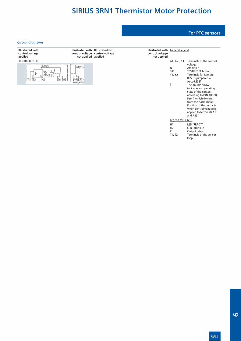
For PTC sensors
Circuit diagrams
Illustrated with control voltage applied
Illustrated with control voltage
not applied
Illustrated with control voltage applied
Illustrated with control voltage
not applied
General legend
3RN10 00, 1 CO A1, A2 , A3
NT/RY1, Y2
⇑
Terminals of the control voltageAmplifierTEST/RESET buttonTerminals for Remote-RESET (jumpered = Auto-RESET)The double arrow indicates an operating state of the contact according to DIN 40900, Part 7 which deviates from the norm (here: Position of the contacts when control voltage is applied to terminals A1 and A2)
Legend for 3RN10
H1H2KT1, T2
LED “READY”LED “TRIPPED”Output relayTerminals of the sensor loop
SIRIUS 3RN1 Thermistor Motor Protection
6/83
6
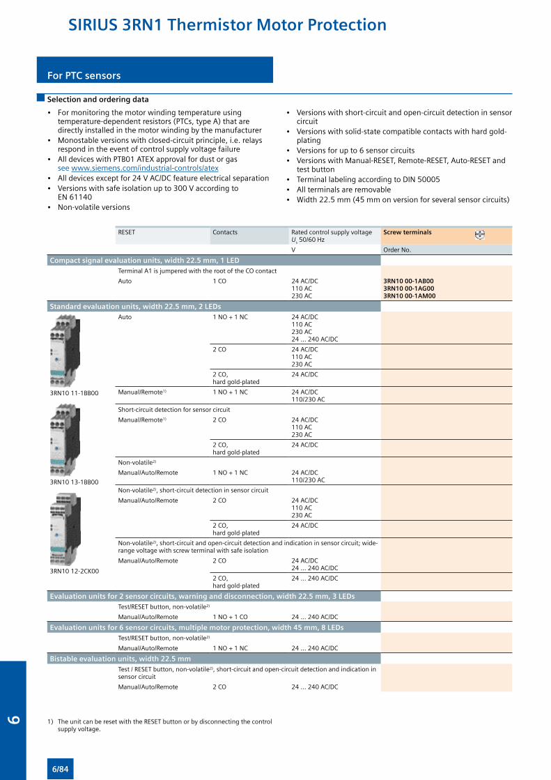
For PTC sensors
Selection and ordering data
• For monitoring the motor winding temperature using temperature-dependent resistors (PTCs, type A) that are directly installed in the motor winding by the manufacturer
• Monostable versions with closed-circuit principle, i.e. relays respond in the event of control supply voltage failure
• All devices with PTB01 ATEX approval for dust or gas see www.siemens.com/industrial-controls/atex
• All devices except for 24 V AC/DC feature electrical separation• Versions with safe isolation up to 300 V according to
EN 61140• Non-volatile versions
• Versions with short-circuit and open-circuit detection in sensor circuit
• Versions with solid-state compatible contacts with hard gold-plating
• Versions for up to 6 sensor circuits• Versions with Manual-RESET, Remote-RESET, Auto-RESET and
test button• Terminal labeling according to DIN 50005• All terminals are removable• Width 22.5 mm (45 mm on version for several sensor circuits)
RESET Contacts Rated control supply voltage Us 50/60 Hz
Screw terminals
V Order No.
Compact signal evaluation units, width 22.5 mm, 1 LED Terminal A1 is jumpered with the root of the CO contact
Auto 1 CO 24 AC/DC110 AC230 AC
3RN10 00-1AB003RN10 00-1AG003RN10 00-1AM00
Standard evaluation units, width 22.5 mm, 2 LEDs
3RN10 11-1BB00
3RN10 13-1BB00
3RN10 12-2CK00
Auto 1 NO + 1 NC 24 AC/DC110 AC230 AC24 … 240 AC/DC
2 CO 24 AC/DC110 AC230 AC
2 CO, hard gold-plated
24 AC/DC
Manual/Remote1) 1 NO + 1 NC 24 AC/DC110/230 AC
Short-circuit detection for sensor circuit
Manual/Remote1) 2 CO 24 AC/DC110 AC230 AC
2 CO, hard gold-plated
24 AC/DC
Non-volatile2)
Manual/Auto/Remote 1 NO + 1 NC 24 AC/DC110/230 AC
Non-volatile2), short-circuit detection in sensor circuit
Manual/Auto/Remote 2 CO 24 AC/DC110 AC230 AC
2 CO, hard gold-plated
24 AC/DC
Non-volatile2), short-circuit and open-circuit detection and indication in sensor circuit; wide-range voltage with screw terminal with safe isolation
Manual/Auto/Remote 2 CO 24 AC/DC24 … 240 AC/DC
2 CO, hard gold-plated
24 … 240 AC/DC
Evaluation units for 2 sensor circuits, warning and disconnection, width 22.5 mm, 3 LEDs Test/RESET button, non-volatile2)
Manual/Auto/Remote 1 NO + 1 CO 24 … 240 AC/DC
Evaluation units for 6 sensor circuits, multiple motor protection, width 45 mm, 8 LEDs Test/RESET button, non-volatile2)
Manual/Auto/Remote 1 NO + 1 NC 24 … 240 AC/DC
Bistable evaluation units, width 22.5 mm Test / RESET button, non-volatile2), short-circuit and open-circuit detection and indication in
sensor circuit
Manual/Auto/Remote 2 CO 24 … 240 AC/DC
1) The unit can be reset with the RESET button or by disconnecting the control supply voltage.
SIRIUS 3RN1 Thermistor Motor Protection
6/84
6

For PTC sensors
Accessories
Use Version Order No.
Push-in lugs
3RP19 03
For 3RN1 Push-in lugs For screw fixing,2 units are required for each device
3RP19 03
SIRIUS 3RN1 Thermistor Motor Protection
6/85
6

Siemens Ltd.Industry SectorControl ProductsR&D Technology CentreKalwa Works, Thane Belapur RoadThane - 400 601Fax: +91 22 33265627E-mail: [email protected]
www.siemens.co.in
Order No.: 104990311 I-IA-CECP-008
Customer Care Toll free no. 1800 209 0987Email: [email protected]
Product upgradation is a continuous process. Hence, data in this datasheet is subject to change without prior notice. For the latest information, please get in touch with our Sales Offices.
Your partnersSales offices:
Chandigarh SCO 188/191, 3rd Floor, Sector-17 C Chandigarh - 160 017 ( : +91 172 4690300 Fax: +91 172 4690399
Chennai Sathak Centre, No.4., Mahatma Gandhi Road Chennai - 600034 ( : +91 44 30474000 Fax: +91 44 30474088
Coimbatore 7th Floor, Global Towers 1057, Avinash Road Coimbatore - 641 018 ( : +91 422 3076300 Fax: +91 422 3076310
Gurgaon Plot No -78, Tower –B Jagatjit Industries Building (JIL) Opposite SBI Academy, Sector-18 Gurgaon - 122015 ( : +91 124 2842000, 3810200
Hyderabad 5-9-19, 4th & 5th Floor, Laxmi Narasinh Estate Opp. Secretariat Road, Saifabad Hyderabad - 500 004 ( : +91 40 30922500 Fax: +91 40 30923145
Jaipur 6, Park Street, Opp. Pink City Petrol Pump, M.I.Road Jaipur - 302 006, Rajasthan ( : +91 141 5152108 Fax: +91 141 2370482
Kolkata 43, Shanti Palli, RashBehari Connector Eastern Metropolitan Bypass Kolkata - 700 042 ( : +91 33 30939000 Fax: +91 33 30939010, 30939013
Lucknow 28/45, Ashok Marg, Opp. Indira Bhawan Lucknow - 226001 ( : +91 522 4031022, 4031000 Fax: +91 522 4031019
Mumbai Business Centre-1 Thane Belapur Road Thane - 400 601 ( : +91 22 39663000 Fax: +91 22 39663721
Nagpur 5th Floor, Land Mark Building Wardha Road, Ramdas Peth Nagpur - 440 010 ( : +91 712 3093000 Fax: +91 712 3093111
Pune Tower B/701-705, ICC Trade Tower 403A, Senapati Bapat Road Pune - 411016 ( : +91 20 30466000 Fax: +91 20 30466060
Vishakhapatnam 2nd Floor, 30-8-47, Lakshmi Narasimha Towers Banu Street, Daba Gardens Visakhapatnam - 530 020, Andhra Pradesh ( : +91 891 3050200 Fax: +91 891 3050222
Guwahati House No. 20, Ushanagar, Dispur Supermarket Guwahati, Assam - 781006 ( : +91 361-2230836 Fax - 0361-2230836 Mobile: +91 9864110684 E-mail: [email protected]
Haridwar 6, Nand Puri, Near Arya Nagar Chowk, Jwalapur Hardwar - 249407, Uttarkhand ( : +91 1334 251943 Mobile: +91 9897070133 E-mail: [email protected]
Haridwar 47, Abhisek Nagar, Kankhal Haridwar - 249408, Uttarakhnad Mobile: +91 9621083333 E-mail: [email protected]
Hospet Ramanand Residency, Flat No. 204 1st Main, Nehru Co-op Colony Hospet - 583203, Karnataka Mobile: +91 9901400227 E-mail: [email protected]
Hubli # 21, Sri Mallikarjuna Nilaya, 1st Floor Somanagowdara Layout, Bengeri Extension, Hubli - 580023, Karnataka ( : +91 836 2282947 Mobile: +91 9880003724 E-mail: [email protected]
Indore Flat No.102, Panchavati Apart. 40 Chandralok Colony, Khajrana Road Indore - 452001, Madhya Pradesh Mobile: +91 9926939993 E-mail: [email protected]
Indore Flat No-206, A Block, Shubh Labh Heights Near Malvi Nagar Chouraha (Near Velocity Multiplex), MR-9, Ring Road Indore - 425010, Madhya Pradesh Mobile: +91 9713013050 E-mail: [email protected]
Jalandhar H.No.943, Urban Estate, Phase I Jalandar - 144022, Punjab ( : +91 181 4613929 Mobile: +91 9876047929 E-mail: [email protected]
Jamshedpur Flat No. B2/D, 9th Phase, Adarshnagar, Sonari Jamshedpur - 831011, Jharkhand Mobile: +91 9836311093 E-mail: [email protected]
Jodhpur 164, Defense Colony, Kamala Nehru Nagar Jodhpur - 342008, Rajasthan ( : +91 291 2760371 Mobile: +91 9828327200 E-mail: [email protected]
Kanpur Flat No. 403, Gulmohar Garden Phase II Near Mariampur Hospital Chain Factory, Shastri Nagar Kanpur - 208005 Mobile: + 91 8009900939 E-mail: [email protected]
Kolhapur Flat No.101, Shrushti Mahabharat Apartment Mahavir Garden To Mahavir College Road Nagala Park, Kolhapur - 416003 ( : +91 231 2663330 Mobile: +91 9881465421 E-mail: [email protected]
Ludhiana H.No.92, Lajpat Nagar, Near Bus Stand Ludhiana - 141002, Punjab ( : +91 161 2770574 Mobile: + 91 9815502480 E-mail: [email protected]
Ludhiana H.No. D-29, New Kitchlu Nagar, Ludhiana Mobile: +91 9878098612 E-mail: [email protected]
Ludhiana H.No.30, 1st Floor, Gobind Nagar, Pakhowal Road Ludhiana - 141013, Punjab Mobile: + 91 9888484066 E-mail: [email protected]
Madurai Anirudh Block F-Top 3, Vasudhara Apartment 84,TPK Main Road, Andalpuram Madurai - 625 003, Tamil Nadu Mobile: +91 9894617776 E-mail: [email protected]
Meerut H-334, Shastri Nagar, Meerut - 250001 Mobile: +91 9837049091 E-mail: [email protected]
Nashik “Aditya Avenue”, Flat No.27, 4th Floor, B-Wing Near Chandak Circle, Tidke Colony Nasik - 422001, Maharashtra Mobile: +91 9822193204 E-mail: [email protected]
Nashik A-12, Eshwar Park, Behind Nasik Cambridge School Opp. Church, Indira Nagar, Nasik - 422009 Mobile: +91 9823477735 E-mail: [email protected]
Pondicherry “Raghavendra ILLAM”, Gnd Floor, No 21 3rd Cross Street, Anna Nagar Pondicherry - 605005 Mobile: +91 9840143536 E-mail: [email protected]
Raipur A-16, Century Cement Colony Din Dayal Upadhyay Nagar, Danganiya Raipur - 492010, Chattisgarh Mobile: +91 9425601849 E-mail: [email protected]
Rajkot “Vrujraj”, Chandanpark Society Opp. Gyanganga Vidhyapith, Nr.Raiya Circle Rajkot - 360005, Gujarat Mobile: +91 9825021026 E-mail: [email protected]
Ranchi HI-187, Harmu Housing Colony, Harmu Ranchi - 834002, Jharkhand Mobile: +91 9234610953 E-mail: [email protected]
Renukoot Above ICICI Prudential Office, Patel Nagar Murdhawa, Distt. Sonebhadra Renukoot - 231217, Uttarpradesh ( : +91 5446 254693 Mobile: +91 9838007897 E-mail: [email protected]
Rourkela Plot No. LCR 618, 1st Phase Chhend Rourkela - 769015 Mobile: +91 9438529778 E-mail: [email protected]
Rudrapur 69, M.I.G. Bhel Colony, Avas Vikas, Rudrapur Udham Singh Nagar, Uttrakhand - 263153 Mobile: +91 9720999887 E-mail: [email protected]
Salem 3/25, Santosh Nagar, PACB Backside Chinnathirupathi, Salem - 8 ( : +91 427 2401981 Mobile: +91 9894617772 E-mail: [email protected]
Surat 32,33, Dattatrey Society, Mora Bhagal Char Rasta Rander Road, Surat - 395005, Gujarat Mobile: +91 9879510191 E-mail: [email protected]
Surat 304, Shreeji Apt., Devikrupa Society Opp. Dholakia Garden, Katargam Surat - 395004, Gujarat Mobile: + 91 9727713634 E-mail: [email protected]
Surat Flat.No. 202, D-1, Suryam Residence Cause Way Road, Opp. Hari Darshan Shinganpor-Dabholi Road, Katargam Surat - 395004, Gujarat Mobile: +91 9925001779 E-mail: [email protected]
Trichy Door No. 106, Grd Flr., 5th Cross Street Vidyasalai Road, Ganapthy Nagar Thiruvanai Koil, Trichy - 605005 ( : +91 431 4345621 Mobile: + 91 9840843121 E-mail: [email protected]
Trivandrum Udayakiran, T.C.No.28/535, Krishnakovil Road Kaithamukku, Trivandrum - 695024, Kerala Mobile: +91 9895979604 E-mail: [email protected]
Udaipur 303, Oasis Park, PP Singhal Marg, Ambavgarh Udaipur - 313001, Rajasthan ( : +91 294 2430345 Mobile: + 91 9829039120 E-mail: [email protected]
Vapi Flat.No.401, A Wing, Madhav Gems, Nutannagar, Valsad Road, Vapi (East), Valsad Dist Vapi - 396191 Mobile: +91 9687668690 E-mail: [email protected]
Vijayawada D.No.37-1-19B, Badavapet, John Street Vijayawada - 520010, Andhra Pradesh ( : +91 866 3060833 Mobile: +91 98664 63639 E-mail: [email protected]
Ahmedabad 3rd Floor, Prerna Arbur Girish Cold Drinks Cross Roads, Off G.C.Road Ahmedabad - 380 009 ( : +91 79 30927600 Fax: +91 79 30927699
Baroda 3rd Floor, OHM Business Park Opp: Balaji Hospital, Ellora Park, Shubhanpura Baroda - 390 023, Gujarat ( : +91 265 3039100 Fax: +91 265 3039190
Bengaluru 1st Floor, Jyoti Mahal, No. 49, St. Marks Road Bengaluru - 560 001 ( : +91 80 33422000 Fax: +91 80 33424131
Bhubaneswar Creative Plaza, 3rd Floor, Mouza Bomikhal (Rasulgarh Square), PS Mancheswar Bhubaneswar - 751 010, Odisha ( : +91 674 2581220 Fax: +91 674 2581330
Territory managers:Aurangabad Flat No. G1, Chanakyapuri, Phase 2 Darga Sutgirni Road, Shanoorwadi Aurangabad - 431001, Maharashtra Mobile: +91 9049005024 E-mail: [email protected]
Belgaum H.No.713, Narvekar Lane, Shahpur Belgaum - 590003, Karnataka ( : +91 831 2495156 Mobile: +91 9740277991 E-mail: [email protected]
Bhilai H.No LIG-47, HUDCO Sector, Bhilai Durg, Chattisgarh - 490 009 Mobile: +91 7869922211 E-mail: [email protected]
Bhopal Flat No-104, Sagar Home Phase-2 Sarvadharma Society, Nayapura Road Bhopal - 462042, Madhya Pradesh Mobile: +91 9977228084 E-mail: [email protected]
Boisar Mahavir Virat, C-wing, Flat No.102, First Floor Mahavir Nagar, Opp to TAPS Colony Boisar (W) - 401501 Mobile: +91 9820533850 E-mail: [email protected]
Calicut Door No. 19/C - 192 CPM House Naderi (PO), Koyilandy (via), Calicut - 673326 ( : +91 9645963636 E-mail: [email protected]
Cochin K.G.Oxford Business Centre 3A, Shreekandath Rd, Ravipuram, Cochin - 682016 ( : +91 4028611/22 Mobile: +91 9387384848 E-mail: [email protected] Mobile: +91 9744511109 E-mail: [email protected]
Dehradun 32, Dhronpuri, Main lane, G.M.S.Road Deharadun-248001, Uttarakhand ( : +91 135 2528212 Mobile: +918650404404 E-mail: [email protected]
Durg Pancham Nivas, B-1, Zone-2, New Adarsh Nagar Durg - 491001, Chhattisgarh Mobile: +91 9425016197 E-mail: [email protected]
Durgapur 14, Dinabandhu Mitra Path Near Kavi Guru Middle Stop SAIL Co-Operative Area, City Centre Durgapur - 713216 Mobile: +919874343052 E-mail: [email protected]
Goa 435 / 10, F2 Bhanumati Bunglow Opp. Sapna Habitat, Chogum Road, Porvorim Bardez, Goa - 403521 Mobile: +91 9860053365 E-mail: [email protected]