
SIP WEB SERVER - optimusaudio.com · SIP WEB SERVER Version 1.1 Page 5 de 20 SIP WEB SERVER...
20
SIP WEB SERVER Version 1.1 Page 1 de 20 SIP WEB SERVER 1. CONNECTING TO THE WEB INTERFACE The web interface is a set of web pages used to configure the various settings available on the SIP Module. This allows the SIP Module to be configured from any computer or device with a web browser. In order to access the Web Interface, you must know the IP address that the web server is serving the pages on. By default, the Modules run DHCP to automatically obtain an IP address. They also run SSDP (Simple Service Discovery Protocol), which allows them to appear in the Network view of a Windows Explorer window (in Windows 7 or higher). You can also examine your DHCP server’s logs to determine what IP address it was assigned. The default username and password are “admin”/“admin”. 2. NAVIGATING WEB INTERFACE The Web Interface has the following elements, which are always present: 1. Page Bar (or Tab Bar): Used to navigate to each of the various configuration pages available in this applicat ion. 2. Login controls: Consisting the auto-logout countdown (indicates the remaining time before the user is automatically logged out), the “Renew” button (immediately extends the auto- logout countdown to the full duration of 10 minutes), and the “Logout” button (pops up a dialog box asking if the user is sure, and if so immediately logs out the user). 3. Status Bar: Displays basic status about VoIP accounts (such as registration status), the system or applicat ion (such as uptime), and other application-specific details. May also display notification boxes when settings have been modified and must be saved, or when settings have been saved and require a restart of the system.
-
Upload
hoangxuyen -
Category
Documents
-
view
236 -
download
5
Transcript of SIP WEB SERVER - optimusaudio.com · SIP WEB SERVER Version 1.1 Page 5 de 20 SIP WEB SERVER...

SIP WEB SERVER Version 1.1 Page 1 de 20
SIP WEB SERVER
1. CONNECTING TO THE WEB INTERFACE The web interface is a set of web pages used to configure the various settings available on the SIP Module. This allows the SIP Module to be configured from any computer or device with a web browser. In order to access the Web Interface, you must know the IP address that the web server is serving the pages on.
By default, the Modules run DHCP to automatically obtain an IP address. They also run SSDP (Simple Service Discovery Protocol), which allows them to appear in the Network view of a Windows Explorer window (in Windows 7 or higher). You can also examine your DHCP server’s logs to determine what IP address it was assigned. The default username and password are “admin”/“admin”.
2. NAVIGATING WEB INTERFACE
The Web Interface has the following elements, which are always present:
1. Page Bar (or Tab Bar): Used to navigate to each of the various configuration pages available in this application. 2. Login controls: Consisting the auto-logout countdown (indicates the remaining time before the user is automatically logged out), the “Renew” button (immediately extends the auto-logout countdown to the full duration of 10 minutes), and the “Logout” button (pops up a dialog box asking if the user is sure, and if so immediately logs out the user). 3. Status Bar: Displays basic status about VoIP accounts (such as registration status), the system or application (such as uptime), and other application-specific details. May also display notification boxes when settings have been modified and must be saved, or when settings have been saved and require a restart of the system.

SIP WEB SERVER Version 1.1 Page 2 de 20
SIP WEB SERVER
4. Page contents: Displays the information and configuration options for the page selected in the Page Bar.To access different pages, click the page’s name in the Page Bar.
The auto-logout function defaults to auto-logout after 10 minutes. The countdown display indicates how much time is remaining. To remain logged in for longer than 10 minutes, click the “Renew” button before the time has expired. To immediately log out, click the “Logout” button; you will be prompted whether or not you really wish to log out. When the auto-logout countdown reaches 0 seconds, you will be automatically logged out without prompting, and any unsaved configuration changes you have made will be lost.
To change settings, edit their values as normal (depending on whether the value is a checkbox, text field, etc.). After making changes, a popup in the Status Bar will indicate that there are unsaved changes. Click the “Save Changes” button to immediately save changes, or the “Revert” button to return all settings on the web page to their previous saved values.
3. SYSTEM CONFIGURATION
3.1 Account’s page The Accounts page is used for configuring SIP accounts.
Each SIP account’s section has the following elements:
1. Account name: The name of this account (based on either the Account Name setting or Username and Domain settings, depending on which are configured)
SIP WEB SERVER Version 1.1 Page 3 de 20
SIP WEB SERVER
2. Account Actions: Controls for this account, which let you selectively disable/enable this account only, and register/deregister this account only. 3. Account Settings Tab Bar: Because SIP accounts have many settings, most of which are not needed for ordinary configuration, the settings are divided in to multiple tabs. 4. Tab contents: Displays the configuration items for the tab selected in the Account Settings Tab Bar.
The most common settings for SIP accounts are on the General tab. Most users should not have to modify settings on the Topology, QoS, or Advanced tabs. Typical SIP account settings For the vast majority of users, only a few settings need to be configured for a SIP account: • Enter the name to be displayed in called equipments in “Display Name”. • Enter your username, extension, or number on the General tab under “Username/Number”. • In case of using a Server enter the SIP server’s name (DNS hostname or IP address) on the
General tab under “Domain” and check “Register with domain”. Often, these settings are all that is needed to correctly configure a SIP account. However, some users may need to enter a few additional settings. • Most SIP servers require authentication to prevent unauthorized access.
- If your SIP server requires a password to register, enter this on the General tab under “Password”.
- Rarely, the authentication username is different from the registration username. If this is the case, enter the authentication username on the Advanced tab under “Auth Username”.
• Some SIP servers and VoIP devices support encryption for call security. - Secure SIP (SIPS), sometimes called SSL or TLS, encrypts the data used to establish VoIP
calls when it is sent between the device and the SIP server (but does not affect encryption of the audio data). It must be supported by and enabled on the SIP server, but need not be supported or enabled on any VoIP endpoints that you wish to call. To enable it, on the Topology tab set “SIP Transport Mode” to “TLS (Secure SIP)”.
- Secure RTP (SRTP) encrypts the audio data being sent in a call (but does not affect encryption of the data used to place or receive calls). It must be supported by the VoIP endpoint you wish to call, although some VoIP endpoints have a setting for optional Secure RTP use.To enable it, on the Topology tab check “Secure RTP”.
• A few additional settings may also be required in rare cases: - If your device is behind a NAT and requires a STUN server to communicate with external
SIP servers or VoIP endpoints, enable the use of STUN for this account on the Topology tab by checking “STUN”.
- If your SIP server operates on a port different from the standard port (5060 for normal SIP, 5061 for Secure SIP), enter this on the Advanced tab under “Proxy port”.
- If your SIP server operates through a SIP proxy, on the Advanced tab enter the proxy’s hostname or IP address under “Proxy server”. If the proxy operates on the standard port (5060 for normal SIP, 5061 for Secure SIP), you can leave “Proxy port” set to 0; otherwise, enter the port under “Proxy port”.
Settings other than the ones mentioned above should only be changed if you know they are required. Using inappropriate values for some settings may prevent the equipment from being able to communicate with the SIP server or VoIP endpoints!

SIP WEB SERVER Version 1.1 Page 4 de 20
SIP WEB SERVER
General tab:
Account Name: The name used to identify this account. It will only be shown on this page and in system log messages. Display Name: Equivalent to “Caller ID”; the name to report to the SIP server and to other callers as your personal name. Depending on the SIP server’s configuration, it may ignore this setting and apply a display name from its own database, or ignore the display name entirely. Username/Number: Equivalent to an “extension” or “phone number”; the number, extension, or address this phone is configured with on the SIP server. Domain : The address of the SIP server. This can be a DNS name (like “sip.company.com”) or numeric IP address (like 12.34.56.78). Register with domain – Determines whether the equipment will register with a SIP server, or operate in peer-to-peer (P2P) mode. In most cases, a centralized SIP server coordinates VoIP calls among endpoints (phones) that register directly with it, and sometimes with external services such as a connection to PSTN (public switched telephone network) through a “termination service”. This is the normal method of using SIP. Most users should therefore leave the Register with domain setting checked. In some cases, a centralized SIP server is not used; this is usually called peer-to-peer mode (P2P). In this case, dialing a SIP URI requires knowing both the username/extension and the address of the peer, which are entered like <[email protected]>. Calls cannot be dialed by entering only a username, since there is no server to route the call. Password: The authentication password to use when connecting to the SIP server.

SIP WEB SERVER Version 1.1 Page 5 de 20
SIP WEB SERVER
Topology tab:
SIP Transport Mode: The method used to communicate with the SIP server. Automatic allows the unit to select an appropriate mode, which will usually result in UDP (which is the normal method for SIP servers) but may attempt TCP if UDP fails. TCP forces the use of a TCP connection. TLS (Secure SIP) forces the use of an encrypted connection. Secure RTP: Enables encryption of RTP audio data. Note that some VoIP endpoints have settings to allow optional use of Secure RTP, which ensures that they can communicate even with a device that does not support or allow Secure RTP. Enabling this setting requires a peer VoIP endpoint to support Secure RTP, which guarantees that audio data will be encrypted, but would result in VoIP endpoints that do not support or allow Secure RTP being unable to establish a call. Local Port: The UDP or TCP port that data will be sent from when communicating with a SIP server. A setting of 0 means to choose a local port randomly, which is the normal behavior. STUN: Enables use of a STUN server to determine the device’s public IP address when it is behind a NAT. This only enables the use of a STUN server; to configure the STUN server’s address and port, use the settings on the Network page. QoS tab:
These configure Quality-of-Service settings, which lets some routers prioritize VoIP data above normal data when bandwidth is constrained.
The default values are set to standard values recognized by all compliant routers. Modifying these values could prevent the unit from being able to communicate with other SIP servers or VoIP endpoints!

SIP WEB SERVER Version 1.1 Page 6 de 20
SIP WEB SERVER
SIP: The DSCP value for SIP data. RTP Audio: The DSCP value for RTP audio data. Advanced tab:
Auth Username: The username to use for authenticating with the SIP server. If this is left blank, the “Username/Number” from the General tab will be used as the authentication username, which is the most common scenario. Proxy: If a SIP proxy is being used, this is the hostname or IP address of the SIP proxy. When no SIP proxy is in use, leave this setting blank. Proxy Port: The port of the SIP server or SIP proxy. A setting of 0 means to use the standard port (5060 for normal SIP servers, 5061 when Secure SIP is being used). Follow these instructions to set the SIP server and SIP proxy correctly: • SIP server at “sip.server.com” on the standard port
o Domain – sip.server.com o Proxy – (leave blank, which is the default) o Proxy Port – 0 (default) or 5060`
• SIP server at “sip.server.com” port 1234 (nonstandard) o Domain – sip.server.com o Proxy – (leave blank, which is the default) o Proxy Port – 1234
• SIP proxy at “proxy.server.com” on the standard port, SIP server at “sip.server.com” on the standard port
o Domain – sip.server.com o Proxy – proxy.server.com o Proxy Port – 0 (default) or 5060

SIP WEB SERVER Version 1.1 Page 7 de 20
SIP WEB SERVER
• SIP proxy at “proxy.server.com” on the standard port, SIP server at “sip.server.com” port 1234 (nonstandard)
o Domain – sip.server.com:1234 o Proxy – proxy.server.com o Proxy Port – 0 (default) or 5060
• SIP proxy at “proxy.server.com” port 9876 (nonstandard) , SIP server at “sip.server.com” on the standard port
o Domain – sip.server.com o Proxy – proxy.server.com o Proxy Port – 9876
• SIP proxy at “proxy.server.com” port 9876 (nonstandard) , SIP server at “sip.server.com” port
1234 (nonstandard) o Domain – sip.server.com:1234 o Proxy – proxy.server.com o Proxy Port – 9876
Registration Lifetime: How long to request registration with the SIP server to last. This value is only a request; the SIP server may impose a minimum or maximum beyond this value. Whatever values the SIP server permits, registration renewal is attempted several times before the end of the duration, usually starting halfway through the duration. Keep-Alive: Enables sending periodic keep-alive data to the SIP server, to ensure that the communication channel remains open. (When running behind a NAT, the NAT may assume the channel is no longer valid and close it prematurely; enabling keep-alive prevents this from happening.) Silence Suppression : Enables detecting when the outgoing audio on calls using this account is nearly silent, and ceasing transmission of RTP audio until voice is detected again. This conserves bandwidth, but requires additional CPU on the device and is not well supported by all VoIP endpoints. (Also called VAD (Voice Activity Detection), although VAD is technically a distinct but necessary component of silence suppression.)
Settings not found in the Accounts page: A few settings typically associated with SIP accounts are actually global settings, and are not found on the Accounts page. STUN server: Although the use of a STUN server is enabled on a per-account basis, only a single STUN server needs to be configured for the whole application. This is configured on the Network page. RTP ports: The ports used to receive RTP audio are configured globally for the whole applications. This is configured on the Network page.

SIP WEB SERVER Version 1.1 Page 8 de 20
SIP WEB SERVER
3.2 Audio page The Audio page has settings for hardware audio (such as speaker and microphone volumes) and digital audio codecs.
Intercom Audio. Hardware audio settings described on “Settings” section. Codec Selection This section displays a list of available and preferred digital audio codecs. Digital audio codecs are ways of encoding audio for transmission between computers. Depending on the algorithms used by a codec, different codecs all have varying levels of sound quality, bandwidth usage, and CPU usage. Not all VoIP implementations support the same set of codecs. Therefore, VoIP devices always indicate to other systems their preferences for codecs to use.

SIP WEB SERVER Version 1.1 Page 9 de 20
SIP WEB SERVER
Available: Lists all codecs that this application supports. Codecs are identified by name, such as “G.711 uLaw” or “DVI4”.
Some basic codecs such as G.711 only support narrowband audio (8 kHz sampling rate, allowing audio to be heard up to 4 kHz), sometimes called “NB”, “voiceband”, or “standard definition”. Other codecs support higher sampling rates, such as wideband audio (16 kHz sampling rate, allowing audio to be hard up to 8 kHz, sometimes called “WB”, “HD”, or “high definition”) or ultra-wideband audio (32 kHz sampling rate, allowing audio to be heard up to 16 kHz, sometimes called “UWB”, “UHD”, or “ultra-high definition”).This device also supports a 48 kHz sampling rate (allowing audio to be heard up to 24 kHz), which it refers to as “CD”.
Preferred: Lists codecs that may be used during a call, in order from most preferred (top) to least preferred (bottom). A codec that is in the Preferred list is enabled, and a codec which is not in the Preferred list is disabled.
To add a codec to the Preferred list, double-click the desired codec in the Available list. You can also click the codec in the Available list to highlight it and click the “Enable” button. To remove a codec from the Preferred list, double-click the desired codec in the Preferred list. You can also click the codec in the Preferred list to highlight it and click the “Disable” button. To change the order of codecs in the Preferred list, click the codec you wish to move to highlight it. Then click the “Move Up” button to move it higher in the list (making it more preferable), or click the “Move Down” button to move it lower in the list (making it less preferable).
Recommended audio codecs As per Internet Standard RFC 7007, all VoIP devices SHOULD include G.711 uLaw as one of their preferred codecs. This is the standard audio codec for PSTN telephones in North America and Japan. It requires very little CPU to process, but it is comparatively bandwidth-intensive and limited to only narrowband audio. We suggest always enabling this codec, but making it the least-preferred codec (or second-least, if G.711 aLaw is enabled) in the Preferred list. G.711 aLaw is similar to G.711 uLaw, with only minor differences in the range of signals it can encode. It is the standard audio codec for PSTN telephones in Europe, and by convention is used for international calls if at least one country uses it. We suggest enabling this codec, but making it the least-preferred codec in the Preferred list.
SIP WEB SERVER Version 1.1 Page 10 de 20
SIP WEB SERVER
Description of available codecs G.711 uLaw and G.711 aLaw (sometimes called “PCMU” and “PCMA”, respectively) are the standard codecs for PSTN telephony. As such, they offer identical quality to land-line telephones. Their CPU usage is very low, but bandwidth is high at 64 kbit/s. G.722 is a wideband audio codec with the same bandwidth requirements as G.711. G.726 has only slightly reduced quality compared to G.711, but uses around half the bandwidth (depending on the bitrate chosen). “Fixed payload” is the most common bitrate (32 kbit/s), but it can also be run at 16, 24, or 40 kbit/s. DVI4 (occasionally called “ADPCM DVI” or “IMA ADPCM”) was formerly recommended as a standard codec for all VoIP devices to support. It also supports wideband and ultra-wideband audio, providing superior audio quality over G.711 using roughly half the bandwidth and without much additional CPU. However, it is not widely used today, and few VoIP devices support it. Linear PCM codecs perform no compression. As a result, they have the highest audio quality and least CPU usage, but also consume the most network bandwidth. They are rarely used in VoIP, and we do not suggest enabling them for ordinary usage. iLBC (Internet Low Bitrate Codec) is designed to offer acceptable audio quality with low bandwidth (15.2 kbit/s for iLBC-20 and 13.33 kbit/s for iLBC-30), and good robustness against lost data packets. In bandwidth-constrained scenarios, it may be useful. However, as its audio quality is comparatively low and it is CPU-intensive, it has limited value for average users. Opus is a new codec that offers very high fidelity for both speech and music without sacrificing low latency. It is expected to replace Speex, SILK, and CELT, and is already supported by many major applications and libraries. Speex is optimized for voice communication over Internet networks, as opposed to many other codecs that were designed for PSTN or mobile networks. It is commonly supported in open-source applications. Its developers, Xiph.Org, consider it obsolete; its successor is Opus, which offers better performance in every aspect. SILK was originally developed for Skype, but has since been made freely available. It offers high audio quality for voice communication and low latency, but is very CPU-intensive. It has been superseded by Opus, which incorporates SILK’s algorithms but adds support for high-fidelity music.

SIP WEB SERVER Version 1.1 Page 11 de 20
SIP WEB SERVER
3.3 Network page The Network page is used to configure network settings, such as IP addresses, STUN server, and RTP ports.
WAN The WAN section configures IP address settings and other features of the WAN interface. Host: This is the system hostname that is reported to applications and services that require one, such as DHCP or DNS. This setting is generally not needed for most users, and can be left as the default setting.

SIP WEB SERVER Version 1.1 Page 12 de 20
SIP WEB SERVER
Domain: This is the DNS domain that the equipment is part of. This value may be ignored if DHCP is used to obtain an IP address automatically. This setting is generally not needed for most users, and can be left as the default setting. Connection Type: Dynamic IP enables DHCP, which attempts to contact a DHCP server to automatically obtain an IP address and DNS servers. Static IP enables manual configuration of IP address and DNS servers. Dynamic IP Address
There are no configuration settings for Dynamic IP. Static IP Address
Address: The IP address of this system. Mask: The subnet mask for this IP address, such as “255.255.0.0”. Default Router: The default gateway, or first hop, for this IP address. DNS Primary/Secondary/Tertiary: The IP addresses of one or more DNS servers to use for name resolution. Additional Settings MTU Size: The Maximum Transmission Unit allowed on the Ethernet connection. The standard for Ethernet networks is 1500, and you should not change this value unless directed to by your network administrator.
Setting an MTU Size other than 1500 may render the device incapable of communicating with any other devices on your network!

SIP WEB SERVER Version 1.1 Page 13 de 20
SIP WEB SERVER
STUN A STUN server is used to allow a host to discover its public IP address if it is located behind a NAT. This may be required for SIP or RTP to work properly. Each VoIP account can be individually configured whether or not to use a STUN server; this is done from that account’s settings on the Accounts page. However, the system only requires a single STUN server to be configured, which is done here.
Server: The hostname or IP address of the STUN server. Port: The port of the STUN server. The standard port for STUN is 3478. RTP Equipment uses a global port range for all incoming RTP streams. It is not possible to configure VoIP accounts to have their own distinct RTP port ranges. Outgoing data streams must necessarily be sent to the port specified by the peer. There is no way to configure or control this locally; only the peer can configure its incoming ports. Although Internet Standard RFC 3551 specifies the use of port 5004 for RTP, there are multiple reasons why this equipment supports configuring a range of ports: • Supporting multiple independent calls simultaneously requires the use of multiple ports, since there is no signaling in SIP to indicate which RTP stream (identified by its SSRC) belongs to a particular call. • In the process of traversing a NAT, the NAT must assign a different port number if port 5004 is already in used by another host behind the NAT. In summary, the port range chosen for incoming RTP is largely arbitrary, and most users should not need to change the default settings.
Port Range: The start and end port numbers to use for incoming RTP streams. These should be even port numbers.
SIP WEB SERVER Version 1.1 Page 14 de 20
SIP WEB SERVER
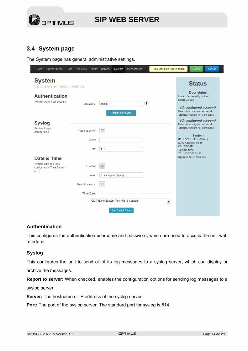
3.4 System page The System page has general administrative settings.
Authentication This configures the authentication username and password, which are used to access the unit web interface. Syslog This configures the unit to send all of its log messages to a syslog server, which can display or
archive the messages.
Report to server: When checked, enables the configuration options for sending log messages to a
syslog server.
Server: The hostname or IP address of the syslog server.
Port: The port of the syslog server. The standard port for syslog is 514.
SIP WEB SERVER Version 1.1 Page 15 de 20
SIP WEB SERVER
Date & Time Because the device does not have battery-backed clocks, it must determine the current date and time anew every time they are restarted. Enabled: When checked, enables using an NTP server to determine the current date and time. Disabling this option will leave the device without a method for knowing the current date and time, which could result in it being unable to interoperate with other devices or network services. Server: The NTP server to use for establishing the current date and time. Daylight savings: Whether daylight saving time (also called “summer time”) is currently in effect. This setting must be changed twice annually (once when entering daylight saving time, and once when returning to standard time). Time zone: The local time zone of this device, which specifies its offset from UTC and its additional offset during daylight saving time, if any.
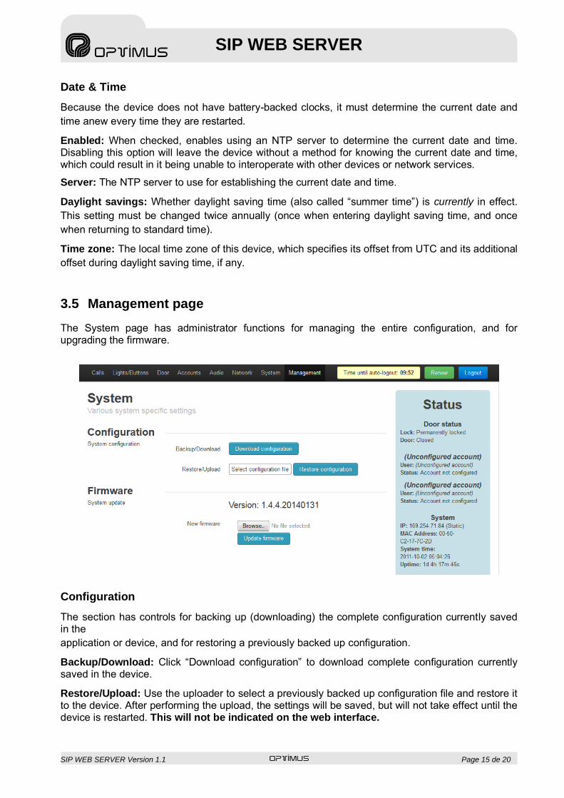
3.5 Management page The System page has administrator functions for managing the entire configuration, and for upgrading the firmware.
Configuration The section has controls for backing up (downloading) the complete configuration currently saved in the application or device, and for restoring a previously backed up configuration. Backup/Download: Click “Download configuration” to download complete configuration currently saved in the device. Restore/Upload: Use the uploader to select a previously backed up configuration file and restore it to the device. After performing the upload, the settings will be saved, but will not take effect until the device is restarted. This will not be indicated on the web interface.

SIP WEB SERVER Version 1.1 Page 16 de 20
SIP WEB SERVER
Firmware This section has information and controls related to the device’s firmware. Version: The version of the firmware currently running on the device. New firmware: Use the uploader to select a BIN firmware image file. When this file is uploaded and verified by the device, it will be installed as the new firmware. This process may take several minutes to complete. During that time, DO NOT disconnect or unplug the device, or interrupt the upgrade process. Once the new firmware is uploaded, the device will verify that it was successfully loaded, make a backup copy of the new firmware, and restart. This process normally takes about 1 minute.

SIP WEB SERVER Version 1.1 Page 17 de 20
SIP WEB SERVER
4. SAMPLE GETTING STARTED GUIDE Follow these basic instructions for getting started with the SIP Module. 1. Connect the SIP Module’s Ethernet port to a network. If you are using Power- over-Ethernet, it will
power on immediately. If not, connect a 5 V DC power supply to the power port. (It is not recommended to connect two different power sources simultaneously.)
2. The SIP Module is controlled through a web interface and set as DHCP. If you don’t use DHCP,
you can find the device easily by connecting a PC, with windows 7 or higher, in its network. This equipment is compatible with SSDP, so it is detected as multimedia equipment in “Network” menu of Windows file browser. It appears as “516POE”. IPV6 needs to be activated in the PC to use this function.
3. The SIP Module will ask for a username and password. The defaults are “admin” and “admin”. 4. On the right side of the page is the Status bar. It shows the current status of the door lock and
sensor, the SIP account status (by default, not configured and unregistered), and the SIP Module’s system information (current IP address, Ethernet MAC address, and system time).
5. To change the IP address settings, go to the Network tab and modify settings in the “WAN” section. To set the network for DHCP, click the “Dynamic IP” radio button. (Note that when using DHCP, you will have to check your DHCP server’s log to find out the SIP Module’s IP address in order to monitor and configure it. For static IP addressing, click the “Static IP” radio button and fill in the relevant IP address fields with values from your network administrator.
6. To change the SIP account settings, go to the Account tab and modify settings in the first account.
Most users will only need to set “Username/Number” (the phone number or extension assigned to this SIP Module) and “Domain” (the hostname or IP address of your SIP server). You may also provide an “Account Name”, which is used only for logging purposes, and a “Display Name”, which may be used by your SIP server depending on its configuration.
If a password is for your SIP server or proxy server, provide it in the “Password” field. If your SIP
server or proxy server requires an authentication username which is different from the name entered in “Username/Number”, enter it on the account’s Advanced tab in the “Auth Username” field.
If needed, you can configure a second SIP account. This account can be used only for receiving
calls, not for placing outgoing calls. 7. After configuring the network and SIP settings for your SIP Module, use the configuration settings
described in the next section to customize the intercom/call box and door lock functionality.

SIP WEB SERVER Version 1.1 Page 18 de 20
SIP WEB SERVER
5. SETTINGS The following settings affect the phone functionality of the SIP Module.
Speaker volume Controls the volume of the speaker. Higher numbers are louder. (Default: 6)
Microphone volume Controls the volume of the microphone. Higher numbers are louder. (Default: 6)
Noise reduction Enables noise reduction for use in noisy environments such as parking garages or outdoors.
Echo canceller Enables echo cancellation, so that callers on the other end do not hear their own echo. Useful when the speaker volume is very high.
Ringback tone Selects the sound to be played while an outgoing call is connecting. “Default” is the normal telephone ringtone, or you can upload a custom ringback tone. To do this, select a WAV file from your PC and press the Submit button; this will upload the file as the custom ringback tone. (Be sure to select the option for playing the custom ringback tone instead of the default ringback tone.) Uploaded files must be of WAV type, uncompressed PCM audio, encoded at 16-bit mono, with a sample rate of 8, 16, 32, or 48 kHz. There is file size limit of 900KB; this gives you just under 1 minute of audio at 8 kHz or just under 30 seconds of audio at 16 kHz. (This limit is shared between all uploaded audio files on the system.)
Outbound ring limit Select the number of rings to allow before giving up on an attempted outgoing call.
Answer inbound calls If selected, incoming phone calls will be answered automatically.
Primary button: Phone number
Pressing the primary button will dial this phone number or extension.
Secondary button Not all units are equipped with a secondary button. This setting indicates whether a secondary button is present on your unit.
Secondary button: Function Selects between different functions for the secondary button: place a call, or unlock the door (when the secondary button is located inside of a locked door and the SIP Module is being used to control the door lock).
Secondary button: Phone number
If the secondary button is configured to dial a number, pressing it will dial this phone number or extension.
Status light 1 function Status light 2 function
SIP Module units may be equipped with one or more status lights. Use these to select what each status light will indicate.

SIP WEB SERVER Version 1.1 Page 19 de 20
SIP WEB SERVER
The following settings affect the door lock functionality of the SIP Module.
Door lock Enables the door lock functionality on the SIP Module Lock type Select the type of lock the SIP Module is controlling: a
fail-secure lock where applying power opens the lock (most electric strike plates), or a fail-safe lock where applying power closes the lock (most magnetic bar
Momentary unlock code During a call, entering this code from a touch-tone phone will cause the door to unlock for a short time to allow entry
Unlock duration When the “Momentary unlock code” is entered, the door will unlock for this duration.
Play tone on unlock When the “Momentary unlock code” is entered correctly, select this to play a tone indicating that the door was successfully unlocked.
Allow leaving door unlocked
Enable or disable codes that set the door to remain permanently unlocked or locked (notwithstanding the momentary unlock feature)
Leave door unlocked code Entering this code from a touch-tone phone during a call will set the door to remain unlocked all the time.
Leave door locked code Entering this code from a touch-tone phone during a call will set the door to remain locked all the time, and the Momentary Unlock Code must be used to open the door.
Door sensor Enables a door sensor which indicates whether the door is open or closed.
Sensor type Select the type of door sensor connected to the SIP Module: normally-open (a closed circuit indicates the door is closed) or normally-closed (a closed circuit indicates the door is open).
Finish momentary unlock early when door is opened
If this option is selected, then when the Momentary Unlock Code is used to open the door, and the sensor indicates that the door has been subsequently opened, the lock will return to the locked position immediately instead of waiting for the full momentary unlock duration.
Door ajar alarm This option will trigger an alarm if the door is left open for an extended period of time.
Alarm period The length of time the door must be left open before the alarm is activated.
Phone number to dial When the alarm is activated, the SIP Module will call this phone number or extension to play the alarm message.

SIP WEB SERVER Version 1.1 Page 20 de 20
SIP WEB SERVER
Alarm message Selects the message to be played when a “door is ajar” alarm call is made. “Default” is a repeating “whoop” alarm tone, or you can upload a custom message. To do this, select a WAV file from your PC and press the Submit button; this will upload the file as the custom message. (Be sure to select the option for playing the custom message instead of the default message.) Uploaded files must be of WAV type, uncompressed PCM audio, encoded at 16-bit mono, with a sample rate of 8, 16, 32, or 48 kHz. There is file size limit of 900KB; this gives you just under 1 minute of audio at 8 kHz or just under 30 seconds of audio at 16 kHz. (This limit is shared between all uploaded audio files on the system.)
Repeat alarm After the alarm is activated the first time, additional alarm calls will be made at this interval until the door is closed.
6. SOFTWARE-BASED FACTORY RESET As a “reset to factory defaults” function, two pins on the Auxiliary I/O Expansion 7-pin connector (labelled “J29”, on the top-right of the board) can be jumpered together using a standard 2 mm electrical jumper. Here are the steps for activating the factory reset: 1. Unplug the SIP Module from power, and if anything is connected to the 7-pin connector, unplug
it as well. 2. Install a 2 mm jumper across pins 2 and 3. 3. Plug in power to the SIP Module (either Power-over-Ethernet or 5V DC can be used). 4. Wait at least 10 seconds for the SIP Module to boot, read the jumper, and apply the factory
reset. 5. Unplug the SIP Module from power. 6. Remove the jumper. 7. Reattach any cables or devices that you detached, and plug in the SIP Module to power it on.
When it boots up, it will have been restored to factory defaults.


![AP-SPS180 SIP Paging Server PT [호환 모드] AP-SPS180 SIP Paging Server • Signaling Server – SIP Application Server, Proxy, Registrar and Location Server (RFC3261) – Multiple](https://static.fdocuments.net/doc/165x107/601be417fc011a5c6b76c626/ap-sps180-sip-paging-server-pt-eeoe-ap-sps180-sip-paging-server-a-signaling.jpg)

![SIP Proxy Server - PLANETplanet.com.tw/storage/products/485/em-sip50v1[1].pdf · 2007-11-22 · SIP-50 SIP Proxy Server User’s Manual 1.3 SIP Proxy Server Front View - Front View:](https://static.fdocuments.net/doc/165x107/5fa54e5371261a635d1a793b/sip-proxy-server-1pdf-2007-11-22-sip-50-sip-proxy-server-useras-manual.jpg)


