Single stage operation - Boston Heating Supplybostonheatingsupply.com/Riello/G750.pdf · Single...
24
Installation, use and maintenance instructions 2903340 (6) - 10/2013 Forced draught natural gas/propane burner Single stage operation CODE MODEL TYPE 3757425 G750 579T GB
Transcript of Single stage operation - Boston Heating Supplybostonheatingsupply.com/Riello/G750.pdf · Single...

Installation, use and maintenance instructions
2903340 (6) - 10/2013
Forced draught natural gas/propane burner
Single stage operation
CODE MODEL TYPE
3757425 G750 579T
GB


1 2903340GB
TABLE OF CONTENTS
Installation instructions and owner's handbook. . . . . . . . . . . . . . . . . . . . . . . . . . . . . . . . . . . . . . . . . . . . . . . . . . . . . .2
General information . . . . . . . . . . . . . . . . . . . . . . . . . . . . . . . . . . . . . . . . . . . . . . . . . . . . . . . . . . . . . . . . . . . . . . . . . .3
Step by step procedure . . . . . . . . . . . . . . . . . . . . . . . . . . . . . . . . . . . . . . . . . . . . . . . . . . . . . . . . . . . . . . . . . . . . . . .3
Installation data . . . . . . . . . . . . . . . . . . . . . . . . . . . . . . . . . . . . . . . . . . . . . . . . . . . . . . . . . . . . . . . . . . . . . . . . . . . . .4
Serial number identification . . . . . . . . . . . . . . . . . . . . . . . . . . . . . . . . . . . . . . . . . . . . . . . . . . . . . . . . . . . . . . . . . . . .4
Burner components identification . . . . . . . . . . . . . . . . . . . . . . . . . . . . . . . . . . . . . . . . . . . . . . . . . . . . . . . . . . . . . . . .4
Burner dimensions. . . . . . . . . . . . . . . . . . . . . . . . . . . . . . . . . . . . . . . . . . . . . . . . . . . . . . . . . . . . . . . . . . . . . . . . . . . 5
Electrode & flame probe adjustments. . . . . . . . . . . . . . . . . . . . . . . . . . . . . . . . . . . . . . . . . . . . . . . . . . . . . . . . . . . . .5
Typical gas train layout . . . . . . . . . . . . . . . . . . . . . . . . . . . . . . . . . . . . . . . . . . . . . . . . . . . . . . . . . . . . . . . . . . . . . . .6
Installing the burner . . . . . . . . . . . . . . . . . . . . . . . . . . . . . . . . . . . . . . . . . . . . . . . . . . . . . . . . . . . . . . . . . . . . . . . . . .7
Installation of sediment trap & burner supply . . . . . . . . . . . . . . . . . . . . . . . . . . . . . . . . . . . . . . . . . . . . . . . . . . . . . . .8
Factory wiring diagram. . . . . . . . . . . . . . . . . . . . . . . . . . . . . . . . . . . . . . . . . . . . . . . . . . . . . . . . . . . . . . . . . . . . . . . .9
Burner head setting . . . . . . . . . . . . . . . . . . . . . . . . . . . . . . . . . . . . . . . . . . . . . . . . . . . . . . . . . . . . . . . . . . . . . . . . .10
Air gate adjustment . . . . . . . . . . . . . . . . . . . . . . . . . . . . . . . . . . . . . . . . . . . . . . . . . . . . . . . . . . . . . . . . . . . . . . . . .11
Pressure working chart . . . . . . . . . . . . . . . . . . . . . . . . . . . . . . . . . . . . . . . . . . . . . . . . . . . . . . . . . . . . . . . . . . . . . .11
Combustion chamber size . . . . . . . . . . . . . . . . . . . . . . . . . . . . . . . . . . . . . . . . . . . . . . . . . . . . . . . . . . . . . . . . . . . .12
Combustion checks . . . . . . . . . . . . . . . . . . . . . . . . . . . . . . . . . . . . . . . . . . . . . . . . . . . . . . . . . . . . . . . . . . . . . . . . .12
Burner start-up cycle . . . . . . . . . . . . . . . . . . . . . . . . . . . . . . . . . . . . . . . . . . . . . . . . . . . . . . . . . . . . . . . . . . . . . . . .12
Start-up cycle diagnostics . . . . . . . . . . . . . . . . . . . . . . . . . . . . . . . . . . . . . . . . . . . . . . . . . . . . . . . . . . . . . . . . . . . .13
Resetting the control box and using diagnostics. . . . . . . . . . . . . . . . . . . . . . . . . . . . . . . . . . . . . . . . . . . . . . . . . . . .13
Owner information & routine maintenance . . . . . . . . . . . . . . . . . . . . . . . . . . . . . . . . . . . . . . . . . . . . . . . . . . . . . . . .17
Appendix - Spare parts . . . . . . . . . . . . . . . . . . . . . . . . . . . . . . . . . . . . . . . . . . . . . . . . . . . . . . . . . . . . . . . . . . . . . .18
Appendix - Burner start up report . . . . . . . . . . . . . . . . . . . . . . . . . . . . . . . . . . . . . . . . . . . . . . . . . . . . . . . . . . . . . . .20

2903340 2 GB
INSTALLATION INSTRUCTIONS AND OWNER'S HANDBOOK
Authorities having jurisdiction should be consulted before installations are made. The owner is required to retainthis manual for future reference.
CAUTION
All gas burners MUST be installed by trained and licensed technicians.
WARNING
Installation of this burner must conform with local codes requirements or, in the absence of localcodes, with the Standard: National Fuel Gas code ANSI Z223.1-1984, and CAN/CGA B149.1 & 2 ANDUL 795. If an external electrical source is utilized, the conversion burner, when installed, must beelectrically grounded in accordance with local codes or, in the absence of local codes, with the na-tional Electrical Code, ANSI/NFPA No. 70-1990 and CSA Electrical Code C22.2 No.0 M1982 & C22.2 No3. 1988.
TECHNICAL SPECIFICATIONSFIRING RATE 250,000 TO 750,000 Btu/hr
NATURAL GAS PROPANE
GAS SUPPLY PRESSURES MIN. 7" wcMAX. 14" wc
MIN. 8" wcMAX. 14" wc
MANIFOLD PRESSURES MIN. 1.4" wcMAX. 2.1" wc
MIN. 1.0" wcMAX. 3.0" wc
POWERMOTORCONTROL MODULE
120 Volts 60 Hz 1 phase233T 4.3 Amps 3250 rpm 325 rad/s.
RMG 88.62
WARNING
WARNING:If the information in these instructions is not followed exactly, a fire or explosion may resultcausing property damage, personal injury or death.
Do not store or use gasoline or any other flammable vapours or liquid in the vicinity of this or anyother appliance.
WHAT TO DO IF YOU SMELL GAS:1) Do not try to light any appliance.2) Do not touch electrical switches; do not use any phone in your building.3) Immediately call your gas supplier from a neighbour's phone.
Follow the gas supplier's instructions.4) If you cannot reach your gas supplier, call the fire department.
Installation and service must be performed by a qualified installer, service agency or the gassupplier.

3 2903340GB
GENERAL INFORMATIONYour Riello gas burner comes to you completely assembled and factory wired, ready for installation.Models equipped with the short combustion head have a fixed flange, which bolts directly to the front of the appliance.When equipped with the long combustion head, the burner comes with a universal flange, which when bolted to theappliance, allows the burner to be adjusted for exact positioning in the combustion zone.
STEP-BY-STEP PROCEDURE1) Remove the burner from the carton, taking care not to lose any of the supplied accessories.
Check for signs of physical damage.2) Bolt the combustion head and burner to the appliance. Be sure to install the supplied mounting gasket.
Ensure that the burner is level (we suggest using a spirit level) and that the combustion head is centred in the ap-pliance port. Refer to page 7 for positioning of combustion head relative to the chamber.
3) Check that all gas train connections are tight and make your connections to the incoming gas supply.a) A sediment trap must be provided.b) If not already installed, a manual shutoff valve must be supplied. This valve must be upstream of the burner gas
train supply connection.c) A 1/8" NPT plugged tapping must be installed immediately upstream of the burner gas train supply connection
and must be accessible for a test gauge. d) If required by local codes, provide gas vent lines at the gas regulators and valve (Riello gas trains are equipped
with vent limiting diaphragms).e) Perform required gas pressure test on incoming gas supply lines.
NOTE: Details of sediment trap, manual gas valve and test point can be found in installation of sediment trap and burnersupply section.
4) Remove the red protective cover by removing the three screws. Make your adjustment of stop gate, (refer to firing ratespecifications and settings charts for details). Replace and secure the air cover plate.
5) Electrical hookup: 120Volt 60 Hz incoming power lines should be connected to Terminals 1 and 2 on burner terminalblock. A manual disconnect switch must be installed in the incoming power lines. Incoming power lines must be rigidconduit or flexible approved cable.
6) Start and check the burner functions as follows:a) Make a final check on both the gas and electrical connections.b) Check that all adjustments have been completed.c) Loosen the screw in the manifold gas test point and install a manometer.d) Switch on power.e) Set the thermostat at its highest setting and press the burner reset button. Allow the burner to run through a com-
plete cycle to check control functions.f) Turn on the manual gas valve and reset the safety. At this stage, the burner will open the air shutter and once it is
open, the burner will prepurge for aprox. 25 seconds. Allow about 66 seconds for the control module to check all the operating circuits.
It may be necessary to repeat the starting cycle several times to free the gas train of entrapped air. If the burner goes tolockout, reset the safety button.
7) With the burner running and flame established, check the manifold gas pressure. Adjust manifold pressure to the cor-rect value for the selected firing rate specified in the FIRING RATE SPECIFICATIONS AND SETTINGS chart. Aftercompleting the setting, remove the manometer and tighten the screws.
NOTE: Do not assume the burner is operating at optimum performance.8) Make your final combustion efficiency test and fine tune the fan air damper as necessary.
Replace the red protective cover and secure with three screws.9) If the burner is installed on a central warm air furnace, affix the supplied warning labels to the furnace fan cover door
(inside and outside).
CAUTION
The hot wire must be connected to the black lead of the relay: neutral to the white lead.Do not reverse the polarity.The burner will not operate with the Phase/Neutral reversed, and the control box may be damaged.Proper earth ground should be connected to the terminal block mounting plate which should be a solid greenwire to Earth Ground.

2903340 4 GB
10) Always do a final set up by checking the gas flow rate by clocking the meter. Do a complete combustion check with proper test equipment to obtain the bestand safe CO² , O², and CO results. This test must be done by a qualified techni-cian. The maximum CO² level for Natural Gas is 10%.
The maximum CO² level for Propane Gas is 12%. The recommended flue gastemperature is from 350 degrees Fahrenheit to 550 degrees Fahrenheit.Fill out the installation data on the label described below and explain the burner’sessential functions (starting and stopping) to the owner. Do not forget to give the dealer or service company’s name and address.
INSTALLATION DATANote: This label is supplied in the package with the burner and should be filledout and affixed to the appliance when the conversion burner is installed.
SERIAL NUMBER IDENTIFICATION Your Riello burner may have been manufactured in more than one location andtherefore there are two possible serial number identification.
The Riello 9 character serial number, example, 06 01 12345, is identified as follows: 06 = Last two digits of the year of manufacture; 01 = Week of manufacture; 12345 = Increment of 1 for each burner produced – specific to
product code – reset to zero each January 1st.
The Riello 15 character serial number, example, 06 A 8511111 00025, is identified as follows: 06 = Last two digits of the year of manufac-
ture; A = BI-week of manufacture; 8511111 = Burner product code;00025 = Increment of 1 for each burner produced
– specific to product code – reset to zeroeach January 1st.
BURNER COMPONENTS IDENTIFICATION1 Air damper 2 Motor3 Ignition transformer connection4 Reset button with lock-out lamp5 Control box RMG 88.626 Wiring terminal block7 Air pressure switch8 Capacitor
(06) (01) (12345)
Year ofmanufacture
BI-week ofmanufacture Increment
(06) (A) (8511111) (00025)
Year ofmanufacture
BI-week ofmanufacture Increment
BI-week ofmanufacture
1
2
3
6
7
4
5
8D7599

5 2903340GB
BURNER DIMENSIONS
ELECTRODE AND FLAME PROBE ADJUSTMENTS
WARNING
Do not turn the ignition electrode. Leave it as shown in the drawing. If the ignition electrode is put near the ionization probe, the amplifier of the control box may be dam-aged.
A
B
D
G FG1
H
J
I
C
D7332
E
6 17/32”-166 mm
8 1/4” - 210 mm
9 1/4” - 235 mm
7 7/
8” -
200
mm
4 3
1/ 3
2”1
28 m
m
60°45°
30°
D7351
NOTE: Actual available insertion length must be measured from tip of end cone to face of mounting gasket.
Model 750 A B C D E F G G1 H I J
inches 11 47/64 13 25/32 2 41/64 1 19/643/4 15 23/64 4 23/32 10 5/8 4 59/64 5 63/64 9 1/16
mm 298 350 67 33 19 389 120 270 125 152 230
6°
=
=
D7339
3.7
Propane adapter Propane orifice
2.0
5/16”
9/16 ”
1
1/8 ”

2903340 6 GB
TYPICAL GAS TRAIN LAYOUTThis gas train scope of supply meets the minimum controls requirements according to CGA and AGA regulations. Anyadditional requirements needed to meet local codes are the responsibility of others.
Key to layout1 Gas supply & flow direction of gas2 Gas supply main shutoff manual valve (field supplied)3 Gas supply pressure test point (field supplied)4 Gas train pipe diameter size(s): burner G750 1” NPT
(reduced at combustion head to 3/4”)5 Gas applance pressure regulator6 Safety shutoff gas valve (VS) 120V operated7 Main gas valve 120V operated:
burner G750 = single stage V1 only8 Firing valve manual shutoff9 Gas burner manifold test point
NOTE: ITEMS 5, 6 & 7 COMBINATION GAS VALVE(S) ASSEMBLIES MAY BE UTILIZED WHERE APPROVED
1 2 3 4 5 6 7 8
See gas supply
9
FIELD SUPPLIED RIELLO SUPPLIED
Ø D7424
pressure range
Gas supply pressure ranges min. max.
Natural gas 7” wc 14” wc
Lp propane gas 8” wc 13” wc

7 2903340GB
INSTALLING THE BURNER
A) Burner chassisB) Combustion head assembly1) Locking nut2) Mounting plate surface3) Insulation gasket
Separate the combustion head of the burner from the chassis(A) by removing the locknut (1). Install the combustion headinto the boiler. Typical insertion depth, the front edge of the combustion headis flush with the inside surface of the appliance mounting sur-face (2).
Use this checklist prior to installation:1) Check the input/output requirements of the boiler/furnace. 2) Check the physical size of the combustion chamber against the thermal requirements of the application and relate this
to the sizing charts.3) Check that there is sufficient air for proper combustion and adequate ventilation.
Local codes should be followed. Check that you have adequate space for servicing the equipment.Riello Burner requires a minimum of 13 inches clear space behind the red cover.This is required to allow easy removal of the cover for servicing and periodic maintenance.
4) Check that the chimney is of sufficient area to handle the exhaust gases. Make sure that the chimney is clear and there are not obstructions. Barometric draft regulators, when used, should be of the double acting type, and must be installed in accordance withthe draft regulator Manufacturer’s instructions. Single acting barometric dampers are not permitted.
5) Affix the supplied operating instructions label to the burner. This label reads as follows: TO START THE BURNER: Switch on power, open manual gas cocks, set the thermostat above ambient temperature. If the burner does not start,press the illuminated re-set button on the burner safety control.
TO SHUT DOWN BURNER: Switch off power supply. If burner is switched off for extended periods, close manual gas cocks.
WARNING
A vent shutoff system shall be applied to a barometric damper installed in the venting system atthe time of conversion of the appliance. This will electrically disconnect the burner should there be a blockage in the vent (chimney).
The installer must identify the main electrical power switch and manual gas shut off valve, for emer-gency conditions. The burner cover must be in place and secured before the burner is placed in oper-ation.
1 3 2
A B
D5108

2903340 8 GB
INSTALLATION OF SEDIMENT TRAP AND BURNER SUPPLY
Gas piping to the burner must be 1/2-inch minimum. Install only a full-ported shutoff valve. The valve must be locatedoutside the appliance jacket, and the pressure gauge port must be accessible.
PRESSURE TEST-OVER 1/2 PSIG.The appliance and its individual shutoff valve must be disconnected from the gas supply piping system during anypressure testing of the system at a test pressure in excess of 1/2 PSIG.
PRESSURE TEST-1/2 PSIG OR LESSThe appliance must be isolated from the gas supply piping system by closing its individual manual shutoff valve dur-ing any testing of the gas supply piping system at test pressures equal to or less than 1/2 PSIG.
1”
NOT SUPPLIED

9 2903340GB
FACTORY WIRING DIAGRAM
Key to lay-outC Capacitor MVF Fuse 6.25ACN... ConnectorsMV Fan motorPA Air pressure switchPGMax Max gas pressure switch
PGMin Min gas pressure switchPS Remote reset push-buttonRMG... Control boxSO Ionization probeTA Ignition transformerTB Burner earthTL Limit thermostat
TM Earth terminal boardTS Safety thermostatT-T 24V operating limit switchT6A FuseV1 Gas valveX12 Terminal board 12 pole
20078045
CONTROL CIRCUITSBurner operation may be controlled by either120V or 24V control systems.The required controls must be connected to theburner as described on the following.
120V CONTROL SYSTEMThe burner provides it own power supply for thecontrol circuits that is switched internal from ter-minal 1)(X12)(L) & 2)(X12)(N), do not applypower on any other terminal or damaged to thecontrol could occur.
24V CONTROL SYSTEMIf firing is to be controlled by a 24V operating sys-tem a 24V switching relay wired as shown in thediagram is required (not supplied – sold sepa-rately). The required 24V operating controls must bewired between the thermostat terminals on the24V-switching relay.
NOTEIf an external electrical source is utilized, the con-version burner, when installed, must be electri-cally grounded with a solid green wire to EarthGround, in accordance with local codes or, in theabsence of local codes, with the National Electri-cal Code ANSI/NFPA 70-1990 and the CSAElectrical Code.
120V CONTROL SYSTEM24V CONTROL SYSTEM
20078047 20078048
CARRIED-OUTIN THE FACTORY
TO BE DONE BYTHE INSTALLER
120V 60 Hz

2903340 10 GB
COMBUSTION HEAD SETTINGTo set combustion head, loosen the Allen screw (A) and move theelbow (B) so that the rear edge of the air tube (C) coincides with theset point number.See firing rate chart for set points. Retighten the Allen screw (A).
BURNER SETUP CHART
Line pressure measured at gas valve with burner firing.
NOTE:The above settings are a starting point for adjustments ONLY; a qualified gas technician using proper test equipment mustdo the final adjustments.Proper CO², 0², and CO readings must be taken and be within regulating code requirements. All the settings above are based on zero (0) over fire-draft.If positive or negative chamber conditions exist some settings changes made be required. For any referral to valve setting, please check the attached manufacturer valve specification.
WARNING
Make sure you are using the correct table for eitherNatural gas or Propane gas.
BTU Input Air Gate Stop Gate Manifold Pressure Line Pressure
NA
TU
AR
AL
GA
S
250,000 1.7 0.0 1.4” w.c. 8.0” w.c.
350,000 1.6 0.0 1.6” w.c. 8.0” w.c.
450,000 1.8 1.0 1.5” w.c. 8.0” w.c.
550,000 2.2 2.0 1.4” w.c. 8.0” w.c.
650,000 2.8 3.0 1.8” w.c. 10.0” w.c.
750,000 3.5 4.0 2.1” w.c. 12.0” w.c.
PR
OP
AN
E
250,000 2.0 0.0 1.0” w.c. 11.0” w.c.
350,000 2.1 0.0 1.4” w.c. 11.0” w.c.
450,000 3.0 1.0 1.5” w.c. 11.0” w.c.
550,000 3.2 2.0 2.1” w.c. 11.0” w.c.
650,000 3.7 3.0 2.6” w.c. 11.0” w.c.
750,000 4.1 4.0 3.0” w.c. 11.0” w.c.
S7015
C
A
B

11 2903340GB
AIR GATE ADJUSTMENTTo regulate the combustion air, adjust the manual air gate (3), by loos-ening the locking screws (4).Once the optimal adjustment is reached, tighten the locking screws(4).
EXAMPLE SETTING - (for natural gas)To set the air intake for a desired burner output of 450,000 Btu/hr, useTABLE to determine the correct air gate setting. In this case, the setting would be 1.8 for natural gas.Turn the manual air gate (3) until the arrow points to 1.8 on the scale.Tighten locking screws (4).
All settings in TABLE are obtained with zero (0) pressure in the com-bustion zone and at normal operating temperatures. i.e., steady statehot conditions.
Note: Burner must be fired ONLY with fuel that is listed on the burnerserial label.
PRESSURE WORKING CHARTThe chart below shows effects of pressure in the combustion zone on the minimum/maximum burner outputs.In this example, with a maximum operating pressure of 1.2 inches water column in the combustion zone, you will beable to obtain a maximum of 600 KBtu/h burner output.
Any change from zero (0) pressure in the combustion zone will affect the KBtu output of the burner. To supply therequired input to the appliance, manifold pressure will have to be adjusted to compensate for this condition.
3
D5231
44
0
0.5
1.0
1.5
200 300 400 500 600 700 800
PRESSURE WORKING CHARTNatural and Propane Gas
S8977
Input - KBTU/h
Bac
k pr
essu
re -
“w
c

2903340 12 GB
COMBUSTION CHAMBER SIZE
NOTES:1) Sizes shown above are for cylindrical or wet base boilers, or air cooled heat exchangers.2) To size the chamber in applications other than wet base boilers, you must calculate area in square inches of the com-
bustion zone required to give you a grate area or floor area to match the BTU inputs according to local authority.3) Recommended firebrick or cerafelt material has a continuous run limited to 2400 degrees Fahrenheit and a melting
point of 3000 degrees Fahrenheit.
COMBUSTION CHECKS
CO2 It is advisable not to exceed a measured reading of 10% CO² for Natural Gas or 12% CO² for Propane Gas takenwith the burner cover in place, to avoid the risk of the formation of CO due to minor changes in wind/draft conditionswhich may occur.
CO For safety reasons, the value of .02% (200ppm) free air sample must not be exceeded.
IONIZATION CURRENTThe minimum amount of current necessary for thecontrol box to operate properly is 5 micro Amps DC. To measure the ionization current, disconnect thered wire connector and insert a DC micrometer inseries with control box terminal 9 and the ionizationprobe, which senses the flame.
BURNER START-UP CYCLE
COMBUSTION CHAMBER SIZERecommended Minimum Sizes
Le
ng
th -
In
ch
es
32
28
20
16
280
40
KBtu/h
36
24
440 600 760 920
MINIMUMDIAMETER16 inches
Ionization probe
Red wire connect
Control boxterminal block
D5006
9
3s40s40smax. 2s max. 2s
D4172
Lock-out, due to ignition failureNormalThermostat
Motor
Ignition transformer
Valves
Flame
Lock-out

13 2903340GB
START-UP CYCLE DIAGNOSTICSDuring start-up, indication is according to the following table:
RESETTING THE CONTROL BOX AND USING DIAGNOSTICSThe control box features a diagnostics function through which any causes of malfunctioning are easily identified (indicator:RED LED). To use this function, you must wait at least 10 seconds once it has entered the safety condition (lockout), andthen press the reset button. The control box generates a sequence of pulses (1 second apart), which is repeated at constant 3-second intervals. Onceyou have seen how many times the light pulses and identified the possible cause, the system must be reset by holding thebutton down for between 1 and 3 seconds.
The methods that can be used to reset the control box and use diagnostics are given below.
RESETTING THE CONTROL BOX To reset the control box, proceed as follows:- Hold the button down for between 1 and 3 seconds.
The burner restarts after a 2-second pause once the button is released.If the burner does not restart, you must make sure the limit thermostat is closed.
VISUAL DIAGNOSTICS Indicates the type of burner malfunction causing lockout.To view diagnostics, proceed as follows:- Hold the button down for more than 3 seconds once the red LED (burner lockout) remains steadily lit.
A yellow light pulses to tell you the operation is done.Release the button once the light pulses. The number of times it pulses tells you the cause of the malfunction, accordingto the coding system indicated in the table on page 10.
SOFTWARE DIAGNOSTICSReports burner life by means of an optical link with the PC, indicating hours of operation, number and type of lockouts,serial number of control box etc ...To view diagnostics, proceed as follows:- Hold the button down for more than 3 seconds once the red LED (burner lockout) remains steadily lit.
A yellow light pulses to tell you the operation is done. Release the button for 1 second and then press again for over 3 seconds until the yellow light pulses again.Once the button is released, the red LED will flash intermittently with a higher frequency: only now can the optical link beactivated.
COLOUR CODE TABLE
Sequences Colour code
Pre-purging
Firing phase
Operation, flame ok
Operating with weak flame signal
Electrical supply lower than ~ 170V
Lockout
Extraneous light
Key to layout: Off Yellow Green Red
RED LED on wait at least 10s Lockout Press reset
for > 3s Pulses Interval3s Pulses

2903340 14 GB
Once the operations are done, the control box’s initial state must be restored using the resetting procedure describedabove.
The sequence of pulses issued by the control box identifies the possible types of malfunction, which are listed in the tablebelow.
BUTTON PRESSED FOR CONTROL BOX STATUS
Between 1 and 3 seconds Control box reset without viewing visual diagnostics.
More than 3 secondsVisual diagnostics of lockout condition:(LED pulses at 1-second intervals).
More than 3 seconds starting from thevisual diagnostics condition
Software diagnostics by means of optical interface and PC (hours of opera-tion, malfunctions etc. can be viewed)
Signal Problem Possible cause Recommended remedy
2 blinks Once the pre-purging phase and safety time have passed, the burner goes into lock-out without the appearance of the flame
The operation solenoid lets little gas through Increase
One of the two solenoid valves does not open.
Replace
Gas pressure too low Increase pressure at governor
Ignition electrode incorrectly adjusted Adjust
Electrode grounded due to broken insulation Replace
High voltage cable defective Replace
High voltage cable deformed by high temper-ature
Replace and protect
Ignition transformer defective Replace
Incorrect valve or transformer electrical wiring Check
Defective control box Replace
A closed valve upline the gas train Open
Air in pipework Bleed air
Gas valves unconnected or with interrupted coil
Check connections or replace coil
3 blinks The burner does not switch on, and the lockout appears
Air pressure switch in operating position Adjust or replace
The burner switches on, but then stops in lockout
- Air pressure switch inoperative due to insuf-ficient air pressure:
Air pressure switch incorrectly adjusted. Adjust or replace
Pressure switch pressure test point pipe blocked
Clean
Poorly adjusted head Adjust
High pressure in the furnace Connect air pressure switch to fan suction line
Lockout during pre-purging phase
Defective motor control contactor(only three-phase version)
Replace
Defective electrical motor Replace
Motor lockout (defective electrical motor) Replace

15 2903340GB
4 blinks The burner switches on, but then stops in lockout
Flame simulation Replace the control box
Lockout when burner stops
Permanent flame in the combustion head or flame simulation
Eliminate persistence of flame or replace control box
6 blinks The burner switches on, but then stops in lockout
Defective or incorrectly adjusted servomotor Adjust or replace
7 blinks The burner goes into lockout immediately following the appear-ance of the flame
The operation solenoid lets little gas through Increase
Ionisation probe incorrectly adjusted Adjust
Insufficient ionisation (less than 5 A) Check probe position
Earth probe Withdraw or replace cable
Burner poorly grounded Check grounding
Phase and neutral connections inverted Invert them
Defective flame detection circuit Replace the control box
Burner lockout mov-ing between 1st and 2nd stages, or between 2nd and 1st stages
Too much air or too little gas Adjust air and gas
Burner goes into lock-out during operation
Probe or ionisation cable grounded Replace worn parts
10 blinks The burner does not switch on, and the lockout appears
Incorrect electrical wiring Check
The burner goes into lockout
Defective control box Replace
Presence of electromagnetic disturbances in the thermostat linesPresence of electromagnetic disturbance
Filter or eliminate
Use the radio disturbance pro-tection kit
No blink The burner does not start
No electrical power supply Close all switches - Check con-nections
A limiter or safety control device is open Adjust or replace
Line fuse blocked Replace
Defective control box Replace
No gas supply Open the manual valves between contactor and train
Mains gas pressure insufficient Contact your GAS COMPANY
Minimum gas pressure switch fails to close Adjust or replace
Servomotor fails to move to min. ignition posi-tion
Replace
Signal Problem Possible cause Recommended remedy

2903340 16 GB
NORMAL OPERATION / FLAME DETECTION TIMEThe control box has a further function to guarantee the correct burner operation (signal: GREEN LED permanently on). Touse this function, wait at least ten seconds from the burner ignition and then press the control box button for a minimum of3 seconds. After releasing the button, the GREEN LED starts flashing as shown in the figure below.
The pulses of the LED constitute a signal spaced by approximately 3 seconds.The number of pulses will measure the probe DETECTION TIME since the opening of gas valves, according to the follow-
ing table:
No blink The burner continues to repeat the start-up cycle, without lockout
The gas pressure in the gas mains lies very close to the value to which the minimum gas pressure switch has been set. The sudden drop in pressure after valve opening causes temporary opening of the pressure switch itself, the valve immediately closes and the burner comes to a halt.Pressure increases again, the pressure switch closes again and the ignition cycle is repeated. And so on
Reduce the minimum gas pres-sure switch intervention pres-sure. Replace the gas filter cartridge.
Ignition with pulsa-tions
Poorly adjusted head Adjust
Ignition electrode incorrectly adjusted Adjust
Incorrectly adjusted fan air damper: too much air
Adjust
Output during ignition phase is too high Reduce
The burner does not move into the 2nd stage
Remote control device TR fails to close Adjust or replace
Defective control box Replace
Defective servomotor Replace
Burner stops with air damper open
Defective servomotor Replace
GREEN LED on wait at least 10s
Press resetfor > 3s Pulses Interval
3s Pulses
SIGNAL FLAME DETECTION TIME This is updated in every burner start-up. Once read, the burnerrepeats the start-up cycle by briefly pressing the control boxbutton.WARNINGIf the result is > 2s, ignition will be retarded. Check the adjust-ment of the hydraulic brake of the gas valve, the air damper andthe combustion head adjustment.
1 blink 0.4s
2 blinks 0.8s
6 blinks 2.8s
Signal Problem Possible cause Recommended remedy

17 2903340GB
OWNER INFORMATION AND ROUTINE MAINTENANCESAFETY LOCKOUTThis burner is equipped with multiple interlocking safety devices. In the event of a failure in the flame, or any blockage ofthe combustion air supply, the burner will “lock out” in a safety condition. In such an event, an illuminated red button willshow on the front of the red cover. To restart the burner, press the button once only. Should the burner return to the lock out condition, call a qualified servicetechnician or your gas company for assistance. In the case of loss of pressure in the gas supply line, the burner will go offon safety. If supplied with an optional gas pressure switch (or field installed), the burner will simply switch off on low gaspressure, and start up again when the gas pressure returns to normal.
NOTE: Keep the area around the burner free and clear of all combustible materials, gasoline and other flammablevapours and liquids. Do not allow any obstructions, which may prevent the free, flow of air to the burner.
MAINTENANCELike all precision equipment, your burner will require periodic maintenance. At an interval of 2 months, you should:
1) If your boiler/furnace has an observation port, visually check the flame.2) Check and clean the air intake louver to remove any buildup of fluff, dust, pet hair, etc.
For any maintenance or repairs over and above those listed, contact your service technician or gas company. THEREARE NO OWNER SERVICEABLE PARTS INSIDE THE BURNER COVER.
Once a year, you should have the burner checked as indicated below, by your local authorized Riello dealer.1) Check burner distributor head and mixing plates. Clean if necessary.2) Check ignition electrode. Clean, adjust, or replace as necessary.3) Check the flame sensor rod (ionization rod) for dirt or carbon build up. Clean, adjust, or replace as necessary.4) Check manifold gas pressure.5) Check all burner adjustments.6) Generally clean all exposed parts and components.7) Repeat combustion tests.
Your Riello 40 gas burner is only part of your heating system.Once every year you should have your heating appliance serviced by a qualified service technician.You should also have the chimney checked, and cleaned if necessary.

2903340 18 GB
APPENDIX - SPARE PARTS

19 2903340GB
N. CODE DESCRIPTION
1 3007246 BURNER BACK COVER
2 3020314 AIR PRESSURE SWITCH
3 3005845 BURNER MOTOR
4 3007288 AIR SWITCH TUBE AND CONNECTOR
5 3007294 AIR PLATE COVER
6 3013072 PRIMARY CONTROL BOX
7 3003784 PRIMARY CONTROL SUB-BASE
8 3006804 FUSE 6.25A
9 3002462 TRANSFORMER - IGNITION
10 3002461 HIGH VOLTAGE LEAD
11 3007310 IONIZATION LEAD
12 3006689 CHASSIS MOUNTING COLLAR
13 3007206 AIR GATE
14 3005799 FAN
15 3007307 CAPACITOR 20 µF
16 3005852 MOUNTING GASKET
17 3005851 UNIVERSAL MOUNTING FLANGE
18 3950471 SHORT COMBUSTION HEAD (280T1)
19 3006697 DRAWER ASSEMBLY ELBOW
20 3006706 ELECTRODE ASSEMBLY
21 3003409 ELECTRODE & IONIZATION CLAMP
22 3020209 IONIZATION ASSEMBLY
23 3006703 NATURAL GAS DIAPHRAGM
24 3006700 DISTRIBUTOR HEAD AND MIXING PLATE
25 3005447 GAS TEST POINT
26 3007525 MANIFOLD
27 3006694 END CONE
28 3000870 HINGE ASSEMBLY
29 3950472 LONG COMBUSTION HEAD (280T2)
30 3006697 DRAWER ASSEMBLY ELBOW
31 3006962 ELECTRODE ASSEMBLY
32 3020210 IONIZATION ASSEMBLY
33 3003409 ELECTRODE & IONIZATION CLAMP
34 3007526 MANIFOLD
35 3005447 GAS TEST POINT
36 3007313 NATURAL GAS TUBE
37 3005849 SEMI FLANGE 2 REQUIRED
38 3006694 END CONE
39 3007283 COMBUSTION HEAD CONNECTOR
40 3006703 NATURAL GAS DIAPHRAGM
41 3006700 DISTRIBUTOR HEAD AND MIXING PLATE
42 3007314 ELECTRODE SUPPORT
43 3007286 AIR TUBE-LONG
44 3000870 HINGE ASSEMBLY
2903340 20 GB
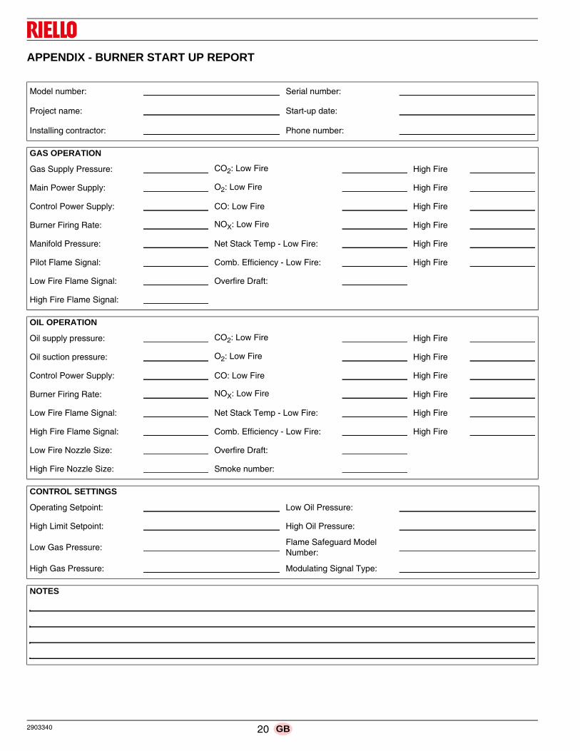
APPENDIX - BURNER START UP REPORT
Model number: Serial number:
Project name: Start-up date:
Installing contractor: Phone number:
GAS OPERATION
Gas Supply Pressure: CO2: Low Fire High Fire
Main Power Supply: O2: Low Fire High Fire
Control Power Supply: CO: Low Fire High Fire
Burner Firing Rate: NOX: Low Fire High Fire
Manifold Pressure: Net Stack Temp - Low Fire: High Fire
Pilot Flame Signal: Comb. Efficiency - Low Fire: High Fire
Low Fire Flame Signal: Overfire Draft:
High Fire Flame Signal:
OIL OPERATION
Oil supply pressure: CO2: Low Fire High Fire
Oil suction pressure: O2: Low Fire High Fire
Control Power Supply: CO: Low Fire High Fire
Burner Firing Rate: NOX: Low Fire High Fire
Low Fire Flame Signal: Net Stack Temp - Low Fire: High Fire
High Fire Flame Signal: Comb. Efficiency - Low Fire: High Fire
Low Fire Nozzle Size: Overfire Draft:
High Fire Nozzle Size: Smoke number:
CONTROL SETTINGS
Operating Setpoint: Low Oil Pressure:
High Limit Setpoint: High Oil Pressure:
Low Gas Pressure:Flame Safeguard Model Number:
High Gas Pressure: Modulating Signal Type:
NOTES


Subject to modifications
RIELLO BURNERS NORTH AMERICA
35 Pond Park Road 1-800-4-RIELLO 2165 Meadowpine Blvd
Hingham, Massachusetts, 1-800-474-3556 Mississauga, Ontario
U.S.A. 02043 Canada L5N 6H6
http://www.riello-burners.com
RIELLO S.p.A.
I-37045 Legnago (VR)
Tel.: +39.0442.630111
http:// www.riello.it
http:// www.rielloburners.com