SINGLE PHASE AC CIRCUITS - WordPress.com · SINGLE PHASE AC CIRCUITS ... Generation of sinusoidal...
58
SINGLE PHASE AC CIRCUITS Definition of Alternating Quantity An alternating quantity changes continuously in magnitude and alternates in direction at regular intervals of time. Important terms associated with an alternating quantity are defined below. 1. Amplitude It is the maximum value attained by an alternating quantity. Also called as maximum or peak value 2. Time Period (T) It is the Time Taken in seconds to complete one cycle of an alternating quantity 3. Instantaneous Value It is the value of the quantity at any instant 4. Frequency (f) It is the number of cycles that occur in one second. The unit for frequency is Hz or cycles/sec. The relationship between frequency and time period can be derived as follows. Time taken to complete f cycles = 1 second Time taken to complete 1 cycle = 1/f second T = 1/f ωt e +Em -Em 0 π/2 π 3π/2 2π T
Transcript of SINGLE PHASE AC CIRCUITS - WordPress.com · SINGLE PHASE AC CIRCUITS ... Generation of sinusoidal...

SINGLE PHASE AC CIRCUITS
Definition of Alternating Quantity
An alternating quantity changes continuously in magnitude and alternates in direction at regular
intervals of time. Important terms associated with an alternating quantity are defined below.
1. Amplitude
It is the maximum value attained by an alternating quantity. Also called as maximum or peak
value
2. Time Period (T)
It is the Time Taken in seconds to complete one cycle of an alternating quantity
3. Instantaneous Value
It is the value of the quantity at any instant
4. Frequency (f)
It is the number of cycles that occur in one second. The unit for frequency is Hz or cycles/sec.
The relationship between frequency and time period can be derived as follows.
Time taken to complete f cycles = 1 second
Time taken to complete 1 cycle = 1/f second
T = 1/f
ωt
e
+Em
-Em
0 π/2 π 3π/2 2π
T

Advantages of AC system over DC system
1. AC voltages can be efficiently stepped up/down using transformer
2. AC motors are cheaper and simpler in construction than DC motors
3. Switchgear for AC system is simpler than DC system
Generation of sinusoidal AC voltage
Consider a rectangular coil of N turns placed in a uniform magnetic field as shown in the figure. The
coil is rotating in the anticlockwise direction at an uniform angular velocity of ω rad/sec.
When the coil is in the vertical position, the flux linking the coil is zero because the plane of the coil
is parallel to the direction of the magnetic field. Hence at this position, the emf induced in the coil is
zero. When the coil moves by some angle in the anticlockwise direction, there is a rate of change of
flux linking the coil and hence an emf is induced in the coil. When the coil reaches the horizontal
position, the flux linking the coil is maximum, and hence the emf induced is also maximum. When
the coil further moves in the anticlockwise direction, the emf induced in the coil reduces. Next when
the coil comes to the vertical position, the emf induced becomes zero. After that the same cycle
repeats and the emf is induced in the opposite direction. When the coil completes one complete
revolution, one cycle of AC voltage is generated.

The generation of sinusoidal AC voltage can also be explained using mathematical equations.
Consider a rectangular coil of N turns placed in a uniform magnetic field in the position shown in the
figure. The maximum flux linking the coil is in the downward direction as shown in the figure. This
flux can be divided into two components, one component acting along the plane of the coil Φmaxsinωt
and another component acting perpendicular to the plane of the coil Φmaxcosωt.
The component of flux acting along the plane of the coil does not induce any flux in the coil. Only
the component acting perpendicular to the plane of the coil ie Φmaxcosωt induces an emf in the coil.
Hence the emf induced in the coil is a sinusoidal emf. This will induce a sinusoidal current in the
circuit given by
tEe
tNe
tdt
dNe
dt
dNe
t
m ω
ωω
ω
ω
sin
sin
cos
cos
max
max
max
=
Φ=
Φ−=
Φ−=
Φ=Φ
tIi m ωsin=
x
ω rad/sec
θ
Фmax
Фmaxcosωt
Фmaxsinωt

Angular Frequency (ω)
Angular frequency is defined as the number of radians covered in one second(ie the angle covered by
the rotating coil). The unit of angular frequency is rad/sec.
Problem 1
An alternating current i is given by
i = 141.4 sin 314t
Find i) The maximum value
ii) Frequency
iii) Time Period
iv) The instantaneous value when t=3ms
i = 141.4 sin 314t
i) Maximum value Im=141.4 V
ii) ω = 314 rad/sec
f = ω/2π = 50 Hz
iii) T=1/f = 0.02 sec
iv) i=141.4 sin(314x0.003) = 114.35A
Average Value The arithmetic average of all the values of an alternating quantity over one cycle is called its average
value
Average value = Area under one cycle
Base
fT
ππ
ω 22
==
tIi m ωsin=
)(2
12
0
tdvVav ωπ
π
∫=

For Symmetrical waveforms, the average value calculated over one cycle becomes equal to zero
because the positive area cancels the negative area. Hence for symmetrical waveforms, the average
value is calculated for half cycle.
Average value = Area under one half cycle
Base
Average value of a sinusoidal current
Average value of a full wave rectifier output
ωt
i
+Im
-Im
0 π 2π
ωt
i
+Im
-Im
0 π 2π
)(1
0
tdvVav ωπ
π
∫=
mm
av
mav
av
m
II
I
ttdII
tidI
tIi
637.02
)(sin1
)(1
sin
0
0
==
=
=
=
∫
∫
π
ωωπ
ωπ
ω
π
π
mm
av
mav
av
m
II
I
ttdII
tidI
tIi
637.02
)(sin1
)(1
sin
0
0
==
=
=
=
∫
∫
π
ωωπ
ωπ
ω
π
π

Average value of a half wave rectifier output
RMS or Effective Value The effective or RMS value of an alternating quantity is that steady current (dc) which when flowing
through a given resistance for a given time produces the same amount of heat produced by the
alternating current flowing through the same resistance for the same time.
ωt
i
+Im
-Im
0 π 2π
R Idc R Iac
base
equaredcurvAreaundersRMS =
Area under squared curve
∫=
π
ωπ
2
0
2 )(2
1tdvVrms
mm
av
mav
av
m
II
I
ttdII
tidI
tIi
318.0
)(sin2
1
)(2
1
sin
0
2
0
==
=
=
=
∫
∫
π
ωωπ
ωπ
ω
π
π

RMS value of a sinusoidal current
RMS value of a full wave rectifier output
RMS value of a half wave rectifier output
ωt
i
+Im
-Im
0 π 2π
ωt
i
+Im
-Im
0 π 2π
ωt
i
+Im
-Im
0 π 2π
mm
rms
mrms
rms
m
II
I
ttdII
tdiI
tIi
707.02
)(sin1
)(2
1
sin
0
22
2
0
2
==
=
=
=
∫
∫
π
π
ωωπ
ωπ
ω
mm
rms
mrms
rms
m
II
I
ttdII
tdiI
tIi
707.02
)(sin1
)(2
1
sin
0
22
2
0
2
==
=
=
=
∫
∫
π
π
ωωπ
ωπ
ω
mm
rms
mrms
rms
m
II
I
ttdII
tdiI
tIi
5.02
)(sin2
1
)(2
1
sin
0
22
2
0
2
==
=
=
=
∫
∫
π
π
ωωπ
ωπ
ω
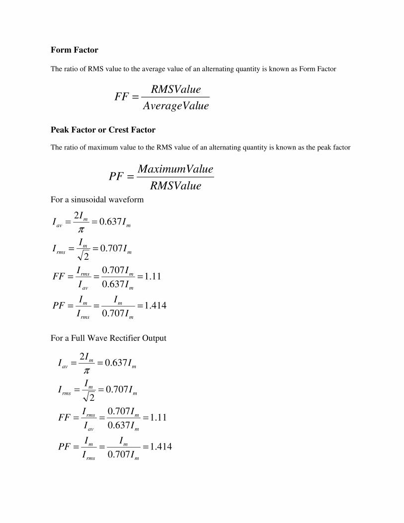
Form Factor The ratio of RMS value to the average value of an alternating quantity is known as Form Factor
Peak Factor or Crest Factor
The ratio of maximum value to the RMS value of an alternating quantity is known as the peak factor
For a sinusoidal waveform
For a Full Wave Rectifier Output
ueAverageVal
RMSValueFF =
RMSValue
ueMaximumValPF =
414.1707.0
11.1637.0
707.0
707.02
637.02
===
===
==
==
m
m
rms
m
m
m
av
rms
mm
rms
mm
av
I
I
I
IPF
I
I
I
IFF
II
I
II
Iπ
414.1707.0
11.1637.0
707.0
707.02
637.02
===
===
==
==
m
m
rms
m
m
m
av
rms
mm
rms
mm
av
I
I
I
IPF
I
I
I
IFF
II
I
II
Iπ

For a Half Wave Rectifier Output
Phasor Representation
An alternating quantity can be represented using
(i) Waveform
(ii) Equations
(iii) Phasor
A sinusoidal alternating quantity can be represented by a rotating line called a Phasor. A phasor is a
line of definite length rotating in anticlockwise direction at a constant angular velocity
The waveform and equation representation of an alternating current is as shown. This sinusoidal
quantity can also be represented using phasors.
ωt
i
+Im
-Im
0 π 2π
25.0
57.1318.0
5.0
5.02
318.0
===
===
==
==
m
m
rms
m
m
m
av
rms
mm
rms
mm
av
I
I
I
IPF
I
I
I
IFF
II
I
II
Iπ
tIi m ωsin=

Draw a line OP of length equal to Im. This line OP rotates in the anticlockwise direction with a
uniform angular velocity ω rad/sec and follows the circular trajectory shown in figure. At any
instant, the projection of OP on the y-axis is given by OM=OPsinθ = Imsinωt. Hence the line OP is
the phasor representation of the sinusoidal current
Phase
Phase is defined as the fractional part of time period or cycle through which the quantity has
advanced from the selected zero position of reference
Phase of +Em is π/2 rad or T/4 sec
Phase of -Em is 3π/2 rad or 3T/4 sec

Phase Difference
When two alternating quantities of the same frequency have different zero points, they are said to
have a phase difference. The angle between the zero points is the angle of phase difference.
In Phase
Two waveforms are said to be in phase, when the phase difference between them is zero. That is the
zero points of both the waveforms are same. The waveform, phasor and equation representation of
two sinusoidal quantities which are in phase is as shown. The figure shows that the voltage and
current are in phase.

Lagging
In the figure shown, the zero point of the current waveform is after the zero point of the voltage
waveform. Hence the current is lagging behind the voltage. The waveform, phasor and equation
representation is as shown.
Leading
In the figure shown, the zero point of the current waveform is before the zero point of the voltage
waveform. Hence the current is leading the voltage. The waveform, phasor and equation
representation is as shown.

AC circuit with a pure resistance
Consider an AC circuit with a pure resistance R as shown in the figure. The alternating voltage v is
given by
---------- (1)
The current flowing in the circuit is i. The voltage across the resistor is given as VR which is the
same as v.
Using ohms law, we can write the following relations
---------------(2)
Where
From equation (1) and (2) we conclude that in a pure resistive circuit, the voltage and current are in
phase. Hence the voltage and current waveforms and phasors can be drawn as below.
tVv m ωsin=
tIi
R
tV
R
vi
m
m
ω
ω
sin
sin
=
==
R
VI m
m =

Instantaneous power
The instantaneous power in the above circuit can be derived as follows
The instantaneous power consists of two terms. The first term is called as the constant power term
and the second term is called as the fluctuating power term.
Average power
From the instantaneous power we can find the average power over one cycle as follows
As seen above the average power is the product of the rms voltage and the rms current.
The voltage, current and power waveforms of a purely resistive circuit is as shown in the figure.
tIVIV
p
tIV
p
tIVp
tItVp
vip
mmmm
mm
mm
mm
ω
ω
ω
ωω
2cos22
)2cos1(2
sin
)sin)(sin(
2
−=
−=
=
=
=
IVP
IVIVP
tdtIVIV
P
tdtIVIV
P
mmmm
mmmm
mmmm
.
222
2cos22
1
2
2cos222
1
2
0
2
0
=
==
−=
−=
∫
∫π
π
ωωπ
ωωπ

As seen from the waveform, the instantaneous power is always positive meaning that the power
always flows from the source to the load.
Phasor Algebra for a pure resistive circuit
Problem 2
An ac circuit consists of a pure resistance of 10Ω and is connected to an ac supply of 230 V, 50 Hz.
Calculate the (i) current (ii) power consumed and (iii) equations for voltage and current.
o
o
000
00
∠=+=+
==
+=∠=
IjIR
jV
R
VI
jVVV
ti
tv
radf
AII
VVViii
WVIPii
AR
VIi
m
m
314sin52.32
314sin25.325
sec/3142
52.322
27.3252)(
526023230)(
2310
230)(
=
=
==
==
==
=×==
===
πω

AC circuit with a pure inductance
Consider an AC circuit with a pure inductance L as shown in the figure. The alternating voltage v is
given by
---------- (1)
The current flowing in the circuit is i. The voltage across the inductor is given as VL which is the
same as v.
We can find the current through the inductor as follows
-------------------(2)
Where
tVv m ωsin=
( )
)2/sin(
)2/sin(
cos
sin
sin
sin
πω
πωω
ωω
ω
ω
ω
−=
−=
−=
=
=
=
=
∫
tIi
tL
Vi
tL
Vi
tdtL
Vi
tdtL
Vdi
dt
diLtV
dt
diLv
m
m
m
m
m
m
L
VI m
mω
=

From equation (1) and (2) we observe that in a pure inductive circuit, the current lags behind the
voltage by 90⁰. Hence the voltage and current waveforms and phasors can be drawn as below.
Inductive reactance
The inductive reactance XL is given as
It is equivalent to resistance in a resistive circuit. The unit is ohms (Ω)
Instantaneous power
The instantaneous power in the above circuit can be derived as follows
As seen from the above equation, the instantaneous power is fluctuating in nature.
L
mm
L
X
VI
fLLX
=
== πω 2
tIV
p
ttIVp
tItVp
vip
mm
mm
mm
ω
ωω
πωω
2sin2
cossin
))2/sin()(sin(
−=
−=
−=
=

Average power
From the instantaneous power we can find the average power over one cycle as follows
The average power in a pure inductive circuit is zero. Or in other words, the power consumed by a
pure inductance is zero.
The voltage, current and power waveforms of a purely inductive circuit is as shown in the figure.
As seen from the power waveform, the instantaneous power is alternately positive and negative.
When the power is positive, the power flows from the source to the inductor and when the power in
negative, the power flows from the inductor to the source. The positive power is equal to the
negative power and hence the average power in the circuit is equal to zero. The power just flows
between the source and the inductor, but the inductor does not consume any power.
Phasor algebra for a pure inductive circuit
0
2sin22
12
0
=
−= ∫
P
ttdIV
P mm
π
ωωπ
)(
9090
0
090
00
L
L
jXIV
XI
V
I
V
jIII
jVVV
=
∠=−∠
∠=
−=−∠=
+=∠=
o
o
o
o

Problem 3
A pure inductive coil allows a current of 10A to flow from a 230V, 50 Hz supply. Find (i) inductance
of the coil (ii) power absorbed and (iii) equations for voltage and current.
AC circuit with a pure capacitance
Consider an AC circuit with a pure capacitance C as shown in the figure. The alternating voltage v is
given by
---------- (1) tVv m ωsin=
)2/314sin(14.14
314sin25.325
sec/3142
14.142
27.3252)(
0)(
073.02
2
2310
230)(
π
πω
π
π
−=
=
==
==
==
=
==
=
Ω===
ti
tv
radf
AII
VVViii
Pii
Hf
XL
fLX
I
VXi
m
m
L
L
L

The current flowing in the circuit is i. The voltage across the capacitor is given as VC which is the
same as v.
We can find the current through the capacitor as follows
-------------------(2)
Where
From equation (1) and (2) we observe that in a pure capacitive circuit, the current leads the voltage
by 90⁰. Hence the voltage and current waveforms and phasors can be drawn as below.
)2/sin(
)2/sin(
cos
sin
πω
πωω
ωω
ω
+=
+=
=
=
=
=
tIi
tCVi
tCVi
dt
dqi
tCVq
Cvq
m
m
m
m
mm CVI ω=

Capacitive reactance
The capacitive reactance XC is given as
It is equivalent to resistance in a resistive circuit. The unit is ohms (Ω)
Instantaneous power
The instantaneous power in the above circuit can be derived as follows
As seen from the above equation, the instantaneous power is fluctuating in nature.
Average power
From the instantaneous power we can find the average power over one cycle as follows
The average power in a pure capacitive circuit is zero. Or in other words, the power consumed by a
pure capacitance is zero.
The voltage, current and power waveforms of a purely capacitive circuit is as shown in the figure.
C
mm
L
X
VI
fCCX
=
==πω 2
11
tIV
p
ttIVp
tItVp
vip
mm
mm
mm
ω
ωω
πωω
2sin2
cossin
))2/sin()(sin(
=
=
+=
=
0
2sin22
12
0
=
= ∫
P
ttdIV
P mm
π
ωωπ
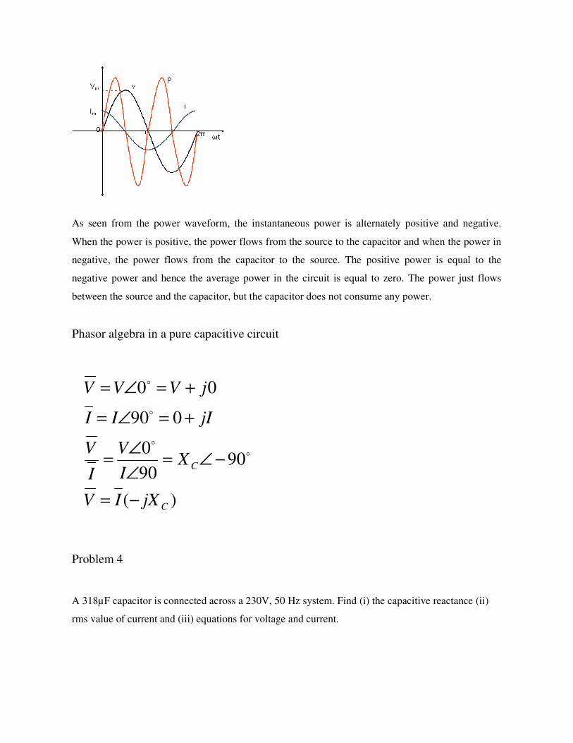
As seen from the power waveform, the instantaneous power is alternately positive and negative.
When the power is positive, the power flows from the source to the capacitor and when the power in
negative, the power flows from the capacitor to the source. The positive power is equal to the
negative power and hence the average power in the circuit is equal to zero. The power just flows
between the source and the capacitor, but the capacitor does not consume any power.
Phasor algebra in a pure capacitive circuit
Problem 4
A 318µF capacitor is connected across a 230V, 50 Hz system. Find (i) the capacitive reactance (ii)
rms value of current and (iii) equations for voltage and current.
)(
9090
0
090
00
C
C
jXIV
XI
V
I
V
jIII
jVVV
−=
−∠=∠
∠=
+=∠=
+=∠=
o
o
o
o

R-L Series circuit
Consider an AC circuit with a resistance R and an inductance L connected in series as shown in the
figure. The alternating voltage v is given by
The current flowing in the circuit is i. The voltage across the resistor is VR and that across the
inductor is VL.
VR=IR is in phase with I
VL=IXL leads current by 90 degrees
With the above information, the phasor diagram can be drawn as shown.
)2/314sin(53.32
314sin25.325
sec/3142
53.322
27.3252)(
23)(
102
1)(
π
πω
π
+=
=
==
==
==
==
Ω==
ti
tv
radf
AII
VVViii
AX
VIii
fCXi
m
m
C
C
tVv m ωsin=

The current I is taken as the reference phasor. The voltage VR is in phase with I and the voltage VL
leads the current by 90⁰. The resultant voltage V can be drawn as shown in the figure. From the
phasor diagram we observe that the voltage leads the current by an angle Φ or in other words the
current lags behind the voltage by an angle Φ.
The waveform and equations for an RL series circuit can be drawn as below.
From the phasor diagram, the expressions for the resultant voltage V and the angle Φ can be derived
as follows.
Where impedance
The impedance in an AC circuit is similar to a resistance in a DC circuit. The unit for impedance is
ohms (Ω).
)sin(
sin
Φ−=
=
tII
tVV
m
m
ω
ω
IZV
XRIV
IXIRV
IXV
IRV
VVV
L
L
LL
R
LR
=
+=
+=
=
=
+=
22
22
22
)()(
22
LXRZ +=

Phase angle
Instantaneous power
The instantaneous power in an RL series circuit can be derived as follows
The instantaneous power consists of two terms. The first term is called as the constant power term
and the second term is called as the fluctuating power term.
Average power
From the instantaneous power we can find the average power over one cycle as follows
=Φ
=Φ
=Φ
=Φ
−
−
−
−
R
L
R
X
IR
IX
V
V
L
L
R
L
ω1
1
1
1
tan
tan
tan
tan
)2cos(2
cos2
)sin()(sin(
Φ−−Φ=
Φ−=
=
tIVIV
p
tItVp
vip
mmmm
mm
ω
ωω
Φ=
Φ=
Φ=
Φ−−Φ= ∫
cos
cos22
cos2
)2cos(2
cos22
12
0
VIP
IVP
IVP
tdtIVIV
P
mm
mm
mmmm
π
ωωπ
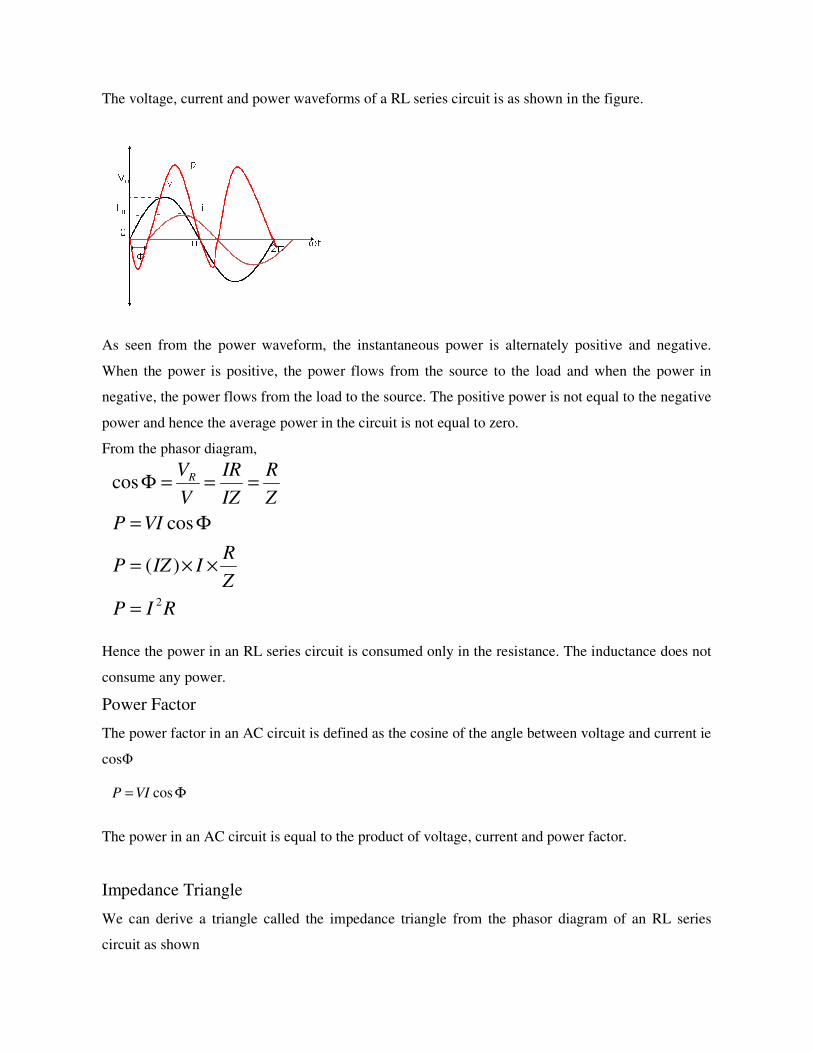
The voltage, current and power waveforms of a RL series circuit is as shown in the figure.
As seen from the power waveform, the instantaneous power is alternately positive and negative.
When the power is positive, the power flows from the source to the load and when the power in
negative, the power flows from the load to the source. The positive power is not equal to the negative
power and hence the average power in the circuit is not equal to zero.
From the phasor diagram,
Hence the power in an RL series circuit is consumed only in the resistance. The inductance does not
consume any power.
Power Factor
The power factor in an AC circuit is defined as the cosine of the angle between voltage and current ie
cosΦ
The power in an AC circuit is equal to the product of voltage, current and power factor.
Impedance Triangle
We can derive a triangle called the impedance triangle from the phasor diagram of an RL series
circuit as shown
RIP
Z
RIIZP
VIP
Z
R
IZ
IR
V
VR
2
)(
cos
cos
=
××=
Φ=
===Φ
Φ= cosVIP

The impedance triangle is right angled triangle with R and XL as two sides and impedance as the
hypotenuse. The angle between the base and hypotenuse is Φ. The impedance triangle enables us to
calculate the following things.
1. Impedance
2. Power Factor
3. Phase angle
4. Whether current leads or lags behind the voltage
Power
In an AC circuit, the various powers can be classified as
1. Real or Active power
2. Reactive power
3. Apparent power
Real or active power in an AC circuit is the power that does useful work in the cicuit. Reactive
power flows in an AC circuit but does not do any useful work. Apparent power is the total power in
an AC circuit.
22
LXRZ +=
Z
R=Φcos
=Φ
−
R
X L1tan

From the phasor diagram of an RL series circuit, the current can be divided into two components.
One component along the voltage IcosΦ, that is called as the active component of current and
another component perpendicular to the voltage IsinΦ that is called as the reactive component of
current.
Real Power
The power due to the active component of current is called as the active power or real power. It is
denoted by P.
P = V x ICosΦ = I2R
Real power is the power that does useful power. It is the power that is consumed by the resistance.
The unit for real power in Watt(W).
Reactive Power
The power due to the reactive component of current is called as the reactive power. It is denoted by
Q.
Q = V x ISinΦ = I2XL
Reactive power does not do any useful work. It is the circulating power in th L and C components.
The unit for reactive power is Volt Amperes Reactive (VAR).
Apparent Power
The apparent power is the total power in the circuit. It is denoted by S.
S = V x I = I2Z
The unit for apparent power is Volt Amperes (VA).
Power Triangle
From the impedance triangle, another triangle called the power triangle can be derived as shown.
22 QPS +=

The power triangle is right angled triangle with P and Q as two sides and S as the hypotenuse. The
angle between the base and hypotenuse is Φ. The power triangle enables us to calculate the following
things.
1. Apparent power
2. Power Factor
The power Factor in an AC circuit can be calculated by any one of the following
methods
Cosine of angle between V and I
Resistance/Impedance R/Z
Real Power/Apparent Power P/S
Phasor algebra in a RL series circuit
Problem 5
A coil having a resistance of 7Ω and an inductance of 31.8mH is connected to 230V, 50Hz supply.
Calculate (i) the circuit current (ii) phase angle (iii) power factor (iv) power consumed
jQPVIS
Z
V
Z
VI
ZjXRZ
VjVV
L
+==
Φ−∠==
Φ∠=+=
∠=+=
*
00 o
22QPS +=
werApparentPo
alPower
S
PCos
Re==Φ

Problem 6
A 200 V, 50 Hz, inductive circuit takes a current of 10A, lagging 30 degree. Find (i) the resistance
(ii) reactance (iii) inductance of the coil
R-C Series circuit
WVIPiv
lagPFiii
lagR
Xii
AZ
VIi
XRZ
fLX
L
L
L
24.2484573.085.18230cos)(
573.0)55cos(cos)(
557
10tantan)(
85.182.12
230)(
2.12107
10108.315014.322
11
2222
3
=××=Φ=
==Φ=
=
=
=
===
Ω=+=+=
Ω=××××==
−−
−
o
oφ
π
Hf
XLiii
ZXii
ZRi
I
VZ
L
L
0318.05014.32
10
2)(
1030sin20sin)(
32.1730cos20cos)(
2010
200
=××
==
Ω=×==
Ω=×==
Ω===
π
φ
φo
o

Consider an AC circuit with a resistance R and a capacitance C connected in series as shown in the
figure. The alternating voltage v is given by
The current flowing in the circuit is i. The voltage across the resistor is VR and that across the
capacitor is VC.
VR=IR is in phase with I
VC=IXC lags behind the current by 90 degrees
With the above information, the phasor diagram can be drawn as shown.
The current I is taken as the reference phasor. The voltage VR is in phase with I and the voltage VC
lags behind the current by 90⁰. The resultant voltage V can be drawn as shown in the figure. From
the phasor diagram we observe that the voltage lags behind the current by an angle Φ or in other
words the current leads the voltage by an angle Φ.
The waveform and equations for an RC series circuit can be drawn as below.
From the phasor diagram, the expressions for the resultant voltage V and the angle Φ can be derived
as follows.
tVv m ωsin=
)sin(
sin
Φ+=
=
tII
tVV
m
m
ω
ω

Where impedance
Phase angle
Average power
Hence the power in an RC series circuit is consumed only in the resistance. The capacitance does not
consume any power.
IZV
XRIV
IXIRV
IXV
IRV
VVV
C
C
CC
R
CR
=
+=
+=
=
=
+=
22
22
22
)()(
22
CXRZ +=
=Φ
=Φ
=Φ
=Φ
−
−
−
−
CR
R
X
IR
IX
V
V
C
C
R
C
ω
1tan
tan
tan
tan
1
1
1
1
RIP
Z
RIIZP
VIP
2
)(
cos
=
××=
= φ

Impedance Triangle
We can derive a triangle called the impedance triangle from the phasor diagram of an RC series
circuit as shown
Phasor algebra for RC series circuit
Problem 7
A Capacitor of capacitance 79.5µF is connected in series with a non inductive resistance of 30Ω
across a 100V, 50Hz supply. Find (i) impedance (ii) current (iii) phase angle (iv) Equation for the
instantaneous value of current
Φ+∠==
Φ−∠=−=
∠=+=
Z
V
Z
VI
ZjXRZ
VjVV
C
o00
)53314sin(828.2
sec/3145014.322
828.2222)(
5330
40tantan)(
250
100)(
504030)(
40105.795014.32
1
2
1
11
2222
6
o
o
+=
=××==
=×==
=
=
=Φ
===
Ω=+=+=
Ω=××××
==
−−
−
ti
radf
AIIiv
leadR
Xiii
AZ
VIii
XRZi
fCX
m
C
C
C
πω
π

R-L-C Series circuit
Consider an AC circuit with a resistance R, an inductance L and a capacitance C connected in series
as shown in the figure. The alternating voltage v is given by
The current flowing in the circuit is i. The voltage across the resistor is VR, the voltage across the
inductor is VL and that across the capacitor is VC.
VR=IR is in phase with I
VL=IXL leads the current by 90 degrees
VC=IXC lags behind the current by 90 degrees
With the above information, the phasor diagram can be drawn as shown. The current I is taken as the
reference phasor. The voltage VR is in phase with I, the voltage VL leads the current by 90⁰ and the
voltage VC lags behind the current by 90⁰. There are two cases that can occur VL>VC and VL<VC
depending on the values of XL and XC. And hence there are two possible phasor diagrams. The
phasor VL-VC or VC-VL is drawn and then the resultant voltage V is drawn.
tVv m ωsin=

VL>VC VL<VC
From the phasor diagram we observe that when VL>VC , the voltage leads the current by an angle
Φ or in other words the current lags behind the voltage by an angle Φ. When VL<VC ,the voltage
lags behind the current by an angle Φ or in other words the current leads the voltage by an angle
Φ.
From the phasor diagram, the expressions for the resultant voltage V and the angle Φ can be derived
as follows.
Where impedance
Phase angle
IZV
XXRIV
IXIXIRV
VVVV
CL
CL
CLR
=
−+=
−+=
−+=
22
22
22
)(
)()(
)(
22 )( CL XXRZ −+=
−=Φ
−=Φ
−=Φ
−
−
−
R
XX
IR
IXIX
V
VV
CL
CL
R
CL
1
1
1
tan
tan
tan

From the expression for phase angle, we can derive the following three cases
Case (i): When XL>XC
The phase angle Ф is positive and the circuit is inductive. The circuit behaves like a series RL circuit.
Case (ii): When XL<XC
The phase angle Ф is negative and the circuit is capacitive. The circuit behaves like a series RC
circuit.
Case (iii): When XL=XC
The phase angle Ф = 0 and the circuit is purely resistive. The circuit behaves like a pure resistive
circuit.
The voltage and the current can be represented by the following equations. The angle Φ is positive or
negative depending on the circuit elements.
Average power
Hence the power in an RLC series circuit is consumed only in the resistance. The inductance and the
capacitance do not consume any power.
Phasor algebra for RLC series circuit
)sin(
sin
Φ±=
=
tII
tVV
m
m
ω
ω
RIP
Z
RIIZP
VIP
2
)(
cos
=
××=
= φ
( )
Φ−∠==
Φ∠=−+=
∠=+=
Z
V
Z
VI
ZXXjRZ
VjVV
CL
o00
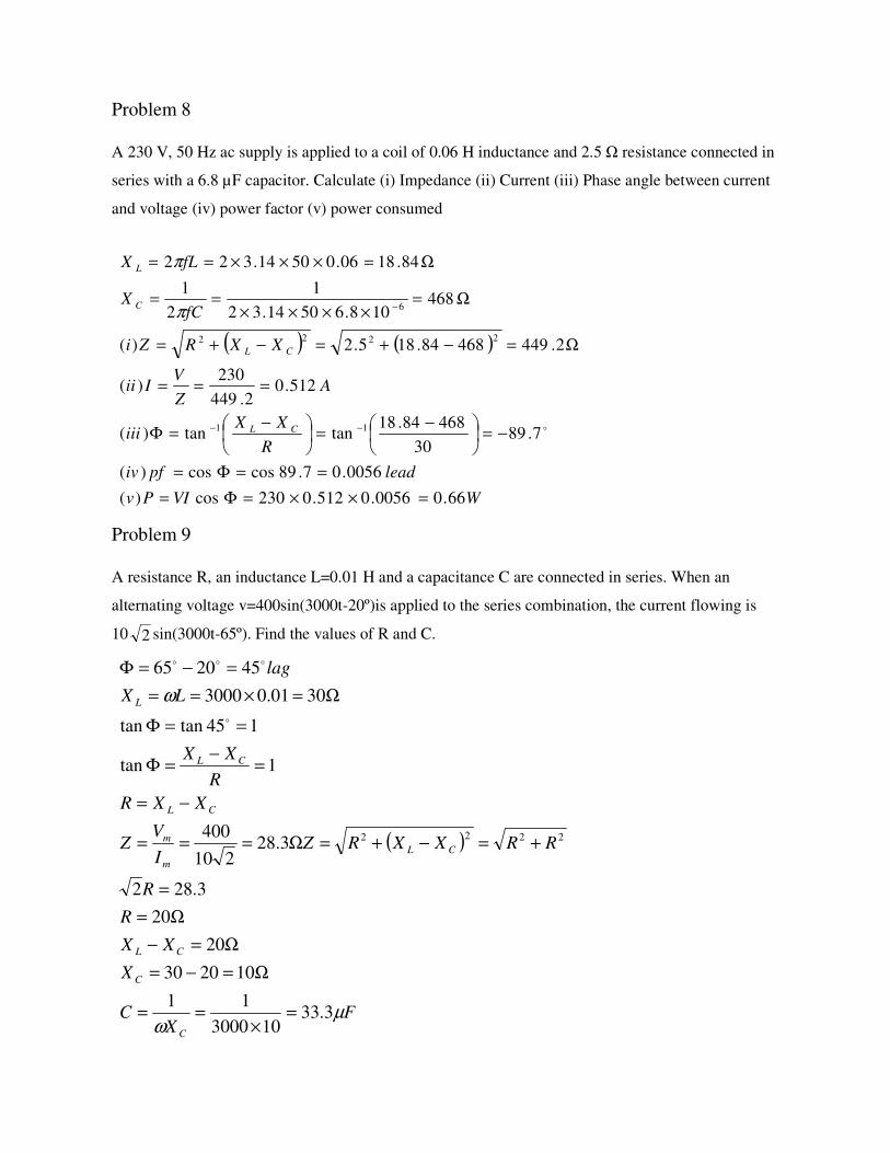
Problem 8
A 230 V, 50 Hz ac supply is applied to a coil of 0.06 H inductance and 2.5 Ω resistance connected in
series with a 6.8 µF capacitor. Calculate (i) Impedance (ii) Current (iii) Phase angle between current
and voltage (iv) power factor (v) power consumed
Problem 9
A resistance R, an inductance L=0.01 H and a capacitance C are connected in series. When an
alternating voltage v=400sin(3000t-20º)is applied to the series combination, the current flowing is
10 sin(3000t-65º). Find the values of R and C.
( ) ( )
WVIPv
leadpfiv
R
XXiii
AZ
VIii
XXRZi
fCX
fLX
CL
CL
C
L
66.00056.0512.0230cos)(
0056.07.89coscos)(
7.8930
46884.18tantan)(
512.02.449
230)(
2.44946884.185.2)(
468108.65014.32
1
2
1
84.1806.05014.322
11
2222
6
=××=Φ=
==Φ=
−=
−=
−=Φ
===
Ω=−+=−+=
Ω=××××
==
Ω=×××==
−−
−
o
π
π
2
( )
FX
C
X
XX
R
R
RRXXRZI
VZ
XXR
R
XX
LX
lag
C
C
CL
CL
m
m
CL
CL
L
µω
ω
3.33103000
11
102030
20
20
3.282
3.28210
400
1tan
145tantan
3001.03000
452065
2222
=×
==
Ω=−=
Ω=−
Ω=
=
+=−+=Ω===
−=
=−
=Φ
==Φ
Ω=×==
=−=Φ
o
ooo

Problem 10
A coil of pf 0.6 is in series with a 100µF capacitor. When connected to a 50Hz supply, the potential
difference across the coil is equal to the potential difference across the capacitor. Find the resistance
and inductance of the coil.
cosΦcoil= 0.6
C=100µF
f = 50Hz
Vcoil=Vc
Problem 11
A current of (120-j50)A flows through a circuit when the applied voltage is (8+j12)V. Determine (i)
impedance (ii) power factor (iii) power consumed and reactive power
HfL
L
RZX
ZR
XZ
IXIZ
VV
fCX
coilL
coilcoil
Ccoil
Ccoil
ccoil
C
081.046.255014.32
1
2
1
46.2509.1983.31
09.196.083.31cos
83.31
83.31101005014.32
1
2
1
2222
6
=×××
==
Ω=−=−=
Ω=×=Φ=
Ω==
=
=
Ω=××××
==−
π
π

Problem 12
The complex Volt Amperes in a series circuit are (4330-j2500) and the current is (25+j43.3)A.
Find the applied voltage.
Problem 13
A parallel circuit comprises of a resistor of 20Ω in series with an inductive reactance 15Ω in one
branch and a resistor of 30Ω in series with a capacitive reactance of 20Ω in the other branch.
Determine the current and power dissipated in each branch if the total current drawn by the parallel
circuit is 10Ļ-30 ⁰A
( ) ( )
VARQ
WP
jQPS
jjjVISiii
lagpfii
Z
jj
j
I
VZi
jI
jV
1840
360
184036050120128)(
179.07.79coscos)(
7.79
11.0
7.7911.011.002.050120
128)(
50120
128
*
=
=
+=
+=+×+==
==Φ=
=Φ
Ω=
∠=+=−
+==
−=
+=
o
o
o
506.863.4325
25004330
3.4325
25004330
*j
j
j
I
SV
jI
jS
+=−
+==
+=
+=
Problem 14
A non inductive resistor of 10Ω is in series with a capacitor of 100µF across a 250V, 50Hz ac
supply. Determine the current taken by the capacitor and power factor of the circuit
Problem 15
An impedance coil in parallel with a 100µF capacitor is connected across a 200V, 50Hz supply. The
coil takes a current of 4A and the power loss in the coil is 600W. Calculate (i) the resistance of the
coil (ii) the inductance of the coil (iii) the power factor of the entire circuit.
( )( )
( ) ( )
( ) ( )
WRIP
WRIP
jI
jjIII
jI
jj
jj
ZZ
ZII
jI
jZ
jZ
7443098.4
2.10282017.7
5.1298.408.186.4
08.68.3566.8
6017.708.68.3
20301520
2030566.8
566.83010
2030
1520
2
2
2
21
2
1
2
11
2
12
1
21
2
1
2
1
=×==
=×==
−∠=+=
−−−=−=
−∠=−=
−++
−×−=
+=
−=−∠=
−=
+=
o
o
o
3.05.72coscos
5.72
5.7249.714.724.283.3110
250
83.3110
83.31101005014.32
1
2
16
===
=
∠=+=−
==
−=−=
Ω=××××
==−
o
o
o
φ
φ
π
pf
jjZ
VI
jjXRZ
fCX
C
C

Problem 16
A series RLC circuit is connected across a 50Hz supply. R=100Ω, L=159.16mH and C=63.7µF. If
the voltage across C is 150Ļ-90⁰V. Find the supply voltage
( )( )( ) ( )
( ) 6365.05.50coscos
5.50
5.5042.4272.3227
83.3107.335.37
83.3107.335.37
83.31
07.335.37
83.31101005014.32
1
2
1
105.05014.32
07.33
2
07.335.3750
5.374
600600
600
504
200
21
21
2
1
6
2222
22
2
=−=Φ=
−=Φ
−∠=−=
−++
−+=
+=
−=−=
+=+=
Ω=××××
==
=××
==
Ω=−=−=
Ω===
==
Ω===
−
o
o
o
pf
jZ
jj
jj
ZZ
ZZZ
jjXZ
jjXRZ
fCX
Hf
XL
RZX
IR
WRIP
I
VZ
C
L
C
L
coilL
coil
π
π
VIZV
jXXjRZ
Aj
j
jX
jI
jjXIV
fCX
fLX
CL
C
CC
C
L
3001003
100)5050(100)(
0350
150150
15090150)(
50107.635014.32
1
2
1
501016.1595014.322
6
3
=×==
Ω=−+=−+=
∠=−
−=
−
−=
−=−∠=−=
Ω=××××
==
Ω=××××==
−
−
o
o
π
π

Problem 17
A circuit having a resistance of 20Ω and inductance of 0.07H is connected in parallel with a series
combination of 50Ω resistance and 60µF capacitance. Calculate the total current, when the parallel
combination is connected across 230V, 50Hz supply.
( )( )( ) ( )
o9.2413.8j3.4 - 7.4
230
j11.9+25.753502220
53502220
5350
2220
5310605014.32
1
2
1
2207.05014.322
21
21
2
1
6
−∠====
=−++
−+=
+=
−=
+=
Ω=××××
==
Ω=×××==
−
ZZ
VI
jj
jj
ZZ
ZZZ
jZ
jZ
fCX
fLX
C
L
π
π

THREE PHASE AC CIRCUITS
A three phase supply is a set of three alternating quantities displaced from each other by an angle of
120⁰. A three phase voltage is shown in the figure. It consists of three phases- phase A, phase B and
phase C. Phase A waveform starts at 0⁰. Phase B waveform stars at 120⁰ and phase C waveform at
240⁰.
The three phase voltage can be represented by a set of three equations as shown below.
The sum of the three phase voltages at any instant is equal to zero.
The phasor representation of three phase voltages is as shown.
)120sin()240sin(
)120sin(
sin
oo
o
+=−=
−=
=
tEtEe
tEe
tEe
mmC
mB
mA
ωω
ω
ω
0=++ CBA eee

The phase A voltage is taken as the reference and is drawn along the x-axis. The phase B voltage
lags behind the phase A voltage by 120⁰. The phase C voltage lags behind the phase A voltage by
240⁰ and phase B voltage by 120⁰.
Generation of Three Phase Voltage
Three Phase voltage can be generated by placing three rectangular coils displaced in space by 120⁰ in
a uniform magnetic field. When these coils rotate with a uniform angular velocity of ω rad/sec, a
sinusoidal emf displaced by 120⁰ is induced in these coils.
Necessity and advantages of three phase systems
3Φ power has a constant magnitude whereas 1Φ power pulsates from zero to peak value at
twice the supply frequency
A 3Φ system can set up a rotating magnetic field in stationary windings. This is not possible
with a 1Φ supply.
For the same rating 3Φ machines are smaller, simpler in construction and have better
operating characteristics than 1Φ machines
To transmit the same amount of power over a fixed distance at a given voltage, the 3Φ system
requires only 3/4th
the weight of copper that is required by the 1Φ system
The voltage regulation of a 3Φ transmission line is better than that of 1Φ line

Phase Sequence
The order in which the voltages in the three phases reach their maximum value
For the waveform shown in figure, phase A reaches the maximum value first, followed by phase B
and then by phase C. hence the phase sequence is A-B-C.
Balanced Supply
A supply is said to be balanced if all three voltages are equal in magnitude and displaced by 120⁰
A three phase supply can be connected in two ways - Either in Delta connection or in Star
connection as shown in the figure.
Delta Connection Star Connection
Balanced Load
A load is said to be balanced if the impedances in all three phases are equal in magnitude and phase
A three phase load can be connected in two ways - Either in Delta connection or in Star
connection as shown in the figure.

Delta Connection Star Connection
Balanced Star Connected Load
A balanced star connected load is shown in the figure. A phase voltage is defined as voltage across
any phase of the three phase load. The phase voltages shown in figure are EA, EB and EC. A line
voltage is defined as the voltage between any two lines. The line voltages shown in the figure are
EAB, EBC and ECA. The line currents are IA, IB and IC. For a star connected load, the phase currents are
same as the line currents.
Using Kirchoff’s voltage law, the line voltages can be written in terms of the phase voltages as
shown below.
ACCA
CBBC
BAAB
EEE
EEE
EEE
−=
−=
−=

The phasor diagram shows the three phase voltages and the line voltage EAB drawn from EA and –EB
phasors. The phasor for current IA is also shown. It is assumed that the load is inductive.
From the phasor diagram we see that the line voltage EAB leads the phase voltage EA by 30⁰. The
magnitude of the two voltages can be related as follows.
Hence for a balanced star connected load we can make the following conclusions.
Line voltage leads phase voltage by 30⁰
Three phase Power
In a single phase circuit, the power is given by VIcosΦ. It can also be written as VphIphcosΦ. The
power in a three circuit will be three times the power in a single phase circuit.
AAAB EEE 330cos2 == o
phl
phl
II
EE
=
= 3
Φ=
Φ=
cos3
cos3
ll
phph
IEP
IEP

Balanced Delta Connected Load
A balanced delta connected load is shown in the figure. The phase currents are IAB, IBC and ICA. The
line currents are IA, IB and IC. For a delta connected load, the phase voltages are same as the line
voltages given by EAB, EBC and ECA.
Using Kirchoff’s current law, the line currents can be written in terms of the phase currents as shown
below.
BCCAC
ABBCB
CAABA
III
III
III
−=
−=
−=

The phasor diagram shows the three voltages EAB, EBC and ECA and the three phase currents IAB, IBC
and ICA lagging behind the respective phase voltages by an angle Φ. This is drawn by assuming that
the load is inductive. From the phase currents IAB and –ICA, the line current IA is drawn as shown in
the figure.
From the phasor diagram we see that the line current IA lags behind the phase phase current IAB by
30⁰. The magnitude of the two currents can be related as follows.
Hence for a balanced delta connected load we can make the following conclusions.
Line current lags behind phase current by 30⁰
Three phase Power
The three phase power for a delta connected load can be derived in the same way as that for a star
connected load.
Measurement of power and power factor by two wattmeter method
The power in a three phase circuit can be measured by connecting two wattmeters in any of the two
phases of the three phase circuit. A wattmeter consists of a current coil and a potential coil as shown
in the figure.
Φ=
Φ=
cos3
cos3
ll
phph
IEP
IEP
ABABA III 330cos2 == o
phl
phl
EE
II
=
= 3

The wattmeter is connected in the circuit in such a way that the current coil is in series and carries
the load current and the potential coil is connected in parallel across the load voltage. The wattmeter
reading will then be equal to the product of the current carried by the current coil, the voltage across
the potential coil and the cosine of the angle between the voltage and current.
The measurement of power is first given for a balanced star connected load and then for a balanced
delta connected load.
(i) Balanced star connected load
The circuit shows a balanced star connected load for which the power is to be measured. Two
wattmeter W1 and W2 are connected in phase A and phase C as shown in the figure.

The current coil of wattmeter W1 carries the current IA and its potential coil is connected across the
voltage EAB. A phasor diagram is drawn to determine the angle between IA and EAB as shown.
From the phasor diagram we determine that the angle between the phasors IA and EAB is (30+Φ).
Hence the wattmeter reading W1 is given by
W1=EABIAcos(30+Φ)
The current coil of wattmeter W2 carries the current IC and its potential coil is connected across the
voltage ECB. From the phasor diagram we determine that the angle between the phasors IC and ECB is
(30-Φ). Hence the wattmeter reading W2 is given by
W2=ECBICcos(30-Φ)
Line voltages EAB=ECB=EL
And line currents IA=IC=IL
Hence
From the above equations we observe that the sum of the two wattmeter reading gives the three
phase power.
(ii) Balanced delta connected load
The circuit shows a balanced delta connected load for which the power is to be measured. Two
wattmeter W1 and W2 are connected in phase A and phase C as shown in the figure.
Φ=+
Φ=+
Φ−+Φ+=+
Φ−=
Φ+=
cos3
)cos30cos2(
)30cos()30cos(
)30cos(
)30cos(
21
21
21
2
1
LL
LL
LLLL
LL
LL
IEWW
IEWW
IEIEWW
IEW
IEW
o

The current coil of wattmeter W1 carries the current IA and its potential coil is connected across the
voltage EAB. A phasor diagram is drawn to determine the angle between IA and EAB as shown.
From the phasor diagram we determine that the angle between the phasors IA and EAB is (30+Φ).
Hence the wattmeter reading W1 is given by
W1=EABIAcos(30+Φ)
The current coil of wattmeter W2 carries the current IC and its potential coil is connected across the
voltage ECB. From the phasor diagram we determine that the angle between the phasors IC and ECB is
(30-Φ). Hence the wattmeter reading W2 is given by

W2=ECBICcos(30-Φ)
Line voltages EAB=ECB=EL
And line currents IA=IC=IL
Hence
From the above equations we observe that the sum of the two wattmeter reading gives the three
phase power.
Determination of Real power, Reactive power and Power factor
Φ=+
Φ=+
Φ−+Φ+=+
Φ−=
Φ+=
cos3
)cos30cos2(
)30cos()30cos(
)30cos(
)30cos(
21
21
21
2
1
LL
LL
LLLL
LL
LL
IEWW
IEWW
IEIEWW
IEW
IEW
o
+
−=Φ=
−=
+=
+
−=Φ
+
−=Φ
Φ=−
Φ=+
Φ−=
Φ+=
−
−
21
121
12
21
21
121
21
12
12
21
2
1
3tancoscos
)(3
3tan
3tan
sin
cos3
)30cos(
)30cos(
WW
WWpf
WWQ
WWP
WW
WW
WW
WW
IEWW
IEWW
IEW
IEW
LL
LL
LL
LL

The power factor can also be determined from the power triangle
From the power triangle,
Wattmeter readings at different Power Factors
2
12
2
21
21
2
12
2
21
12
21
)(3)(cos
)(3)(
)(3
WWWW
WW
S
Ppf
WWWWS
WWQ
WWP
−++
+==Φ=
−++=
−=
+=
21
2
1
2
3)30cos()30cos(
2
3)30cos()30cos(
0
)(
WW
IEIEIEW
IEIEIEW
upfi
LLLLLL
LLLLLL
=
==Φ−=
==Φ+=
=Φ o
12
2
1
2
)3030cos()30cos(
2)3030cos()30cos(
30
866.0)(
WW
IEIEIEW
IEIEIEW
pfii
LLLLLL
LLLLLL
=
=−=Φ−=
=+=Φ+=
=Φ
=
o

Problem 1
A balanced 3Φ delta connected load has per phase impedance of (25+j40)Ω. If 400V, 3Φ supply is
connected to this load, find (i) phase current (ii) line current (iii) power supplied to the load.
LLLLLL
LLLL
IEIEIEW
IEIEW
pfiii
2
3)6030cos()30cos(
0)6030cos()30cos(
60
5.0)(
2
1
=−=Φ−=
=+=Φ+=
=Φ
=
o
0)30cos(
0)30cos(
60
5.0)(
2
1
>Φ−=
<Φ+=
>Φ
<
LL
LL
IEW
IEW
pfiv
o
21
2
1
2)9030cos()30cos(
2)9030cos()30cos(
90
0)(
WW
IEIEIEW
IEIEIEW
pfv
LLLLLL
LLLLLL
−=
−=−=Φ−=
=+=Φ+=
=Φ
=
o
WP
IEPiii
AIIii
AZ
EIi
EVE
Z
Z
LL
phL
ph
ph
ph
phL
ph
ph
76.5397
60cos7.144003cos3)(
907.1448.833)(
6048.86017.47
400)(
400
6017.47
6025
40tan
17.474025
1
22
=
×××=Φ=
−∠=×==
−∠=∠
==
==
Ω∠=
=
=Φ
Ω=+=
−
o
o
o
o
o
o
Problem 2
Two wattmeter method is used to measure the power absorbed by a 3Φ induction motor. The
wattmeter readings are 12.5kW and -4.8kW. Find (i) the power absorbed by the machine (ii) load
power factor (iii) reactive power taken by the load.
Problem 3
Calculate the active and reactive components of each phase of a star connected 10kV, 3Φ alternator
supplying 5MW at 0.8 pf.
Problem 4
A 3Φ load of three equal impedances connected in delta across a balanced 400V supply takes a line
current of 10A at a power factor of 0.7 lagging. calculate (i) the phase current (ii) the total power (iii)
the total reactive kVAR
[ ]
( )( ) ( ) kVARWWQiii
pf
WW
WWii
kWWWPi
kWW
kWW
96.295.128.433)(
2487.06.75coscos
6.7589.3tan
89.38.45.12
5.128.433tan)(
7.78.45.12)(
8.4
5.12
12
1
21
12
21
2
1
=−−=−=
=−=Φ=
−=−=Φ
−=
−
−−=
+
−=Φ
=−=+=
−=
=
−
o
o
MVARIEQ
MWP
AE
PI
IEP
pf
MWP
kVE
phphph
ph
L
L
LL
L
25.187.36sin8.3603
1010sin
7.1663
105
84.3608.010103
105
cos3
cos3
87.36
8.0cos
5
10
6
3
6
=×××
=Φ=
=×
=
=×××
×=
Φ=
Φ=
=Φ
=Φ=
=
=
o
o

Problem 5
The power flowing in a 3Φ, 3 wire balanced load system is measured by two wattmeter method. The
reading in wattmeter A is 750W and wattmeter B is 1500W. What is the power factor of the system?
Problem 6
A 3Φ star connected supply with a phase voltage of 230V is supplying a balanced delta connected
load. The load draws 15kW at 0.8pf lagging. Find the line currents and the current in each phase of
the load. What is the load impedance per phase.
kVARIEQiii
kWIEPii
AI
Ii
lagpf
AI
EVE
LL
LL
Lph
L
phL
94.457.45sin104003sin3)(
84.47.0104003cos3)(
8.53
10
3)(
57.45
7.0cos
10
400
=×××=Φ=
=×××=Φ=
===
=Φ
=Φ=
=
==
o
o
866.030coscos
30
1500750
75015003tan3tan
1500
750
1
21
121
2
1
==Φ=
=Φ
+
−=
+
−=Φ
=
=
−−
o
o
pf
WW
WW
WW
WW

AE
PI
laggingpf
kWP
VVE
VE
Alternator
L
L
L
ph
17.27cos3
8.0cos
15
37.3982303
230
=Φ
=
=Φ=
=
=×=
=
Ω==
==
=
==
4.25
68.153
17.27
37.398
ph
ph
ph
Lph
L
Lph
I
EZ
AI
I
AI
VEE
Load