Single Package Vertical Heat Pumps - lib.store.yahoo.net · PDF filewatts 738 750 758 805 813...
16
PRPRF_VPAK_COMM_2017 (Rev.1) 9521 4200_01 • Up to 10.4 EER • Completely self- contained; no outside condensing unit • Can be installed from any interior side (front, right or left) • Patented telescoping plenum (accessory) easily adapts to more installations • Unique free-floating chassis and fully insulated cabinets for improved sound characteristics and unit performance • Condensate removal system uses slinger ring technology to cool the coil and increase efficiency • Primary condensate removal system provided thru 3/4" pipe fittings for more placement options • Secondary overflow from primary drain* • Pre wired, charged and piped • Two-speed fan control from wireless or wired wall thermostat • Safety power disconnect • Weighs as little as 125 lbs. • 5 YR. limited warranty- includes labor Features Single Package Vertical Heat Pumps *24000 Btu models (VHA24K & VHA24R) and 18000 BTU model (VHA18K & VHA18R) use secondary gravity-fed drain (VPDP1). PRODUCT PROFILE Vert-I-Pak ® THE EXPERTS IN ROOM AIR CONDITIONING
Transcript of Single Package Vertical Heat Pumps - lib.store.yahoo.net · PDF filewatts 738 750 758 805 813...

PRPRF_VPAK_COMM_2017 (Rev.1) 9521 4200_01
• Up to 10.4 EER
• Completely self-contained; no outside condensing unit
• Can be installed from any interior side (front, right or left)
• Patented telescoping plenum (accessory) easily adapts to more installations
• Unique free-floating chassis and fully insulated cabinets for improved sound characteristics and unit performance
• Condensate removal system uses slinger ring technology to cool the coil and increase efficiency
• Primary condensate removal system provided thru 3/4" pipe fittings for more placement options
• Secondary overflow from primary drain*
• Pre wired, charged and piped
• Two-speed fan control from wireless or wired wall thermostat
• Safety power disconnect
• Weighs as little as 125 lbs.
• 5 YR. limited warranty-includes labor
Features
Single Package Vertical Heat Pumps
*24000 Btu models (VHA24K & VHA24R) and 18000 BTU model (VHA18K & VHA18R) use secondary gravity-fed drain (VPDP1).
PRODUCT PROFILE
Vert-I-Pak®
THE EXPERTS IN ROOM AIR CONDITIONING

2
CHASSIS SPECIFICATIONS K-Series models 230/208V, R-Series models 265V
MODEL VHA09K VHA09R VHA12K VHA12R VHA18K VHA18R VHA24K VHA24R
COOLING DATA
COOLING BTU 9400/9400 9400 12200/12000 12400 18200/18000 18000 23000/22800 22400
POWER (W) 905/905 915 1220/1200 1240 1825/1800 1815 2527/2505 2475
EER 10.4/10.4 10.3 10.0/10.0 10.0 10.0/10.0 10.0 9.1/9.1 9.1
SENSIBLE HEAT RATIO 0.77 0.77 0.75 0.77 0.67 0.66 0.70 0.70
HEATER SIZE (kW) 2.5/3.4/5.0 2.5/3.4/5.0 2.5/3.4/5.0 2.5/3.4/5.0 2.5/3.4/5.0 2.5/3.4/5.0 2.5/3.4/5.0/7.5/10.0 2.5/3.4/5.07/7.5/10.0
HEAT PUMP DATA
REVERSE HEATING BTU 8400/8400 8500 11100/10900 11300 16800/16400 16700 20000/20000 20000
COP @ 47F 3.0/3.0 3.0 3.0/3.0 3.0 3.0/3.0 3.0 3.0/3.0 3.0
HEATING POWER (W) 830/830 820 1075/1050 1095 1650/1600 1620 1953/1953 1950
HEATING CURRENT (A) 4.0/4.0 3.2 5.0/5.3 4.5 7.8/8.3 6.9 8.5/9.4 8.1
ELECTRICAL DATA
VOLTAGE (1 PHASE, 60 HZ) 230/208 265 230/208 265 230/208 265 230/208 265
VOLT RANGE 253-197 292/239 253-197 292/239 253-197 292-239 253-197 292-239
COOLING CURRENT (A) 4.3/4.3 3.5 5.7/5.9 5.1 8.6/9.2 7.6 10.9/10.6 9.7
AMPS L.R 21.0 21.0 30.0 30.0 42.0 42.0 46.0 46.0
AMPS F.L. 3.5 3.5 4.8 4.8 7.8 7.8 9.5 9.5
INDOOR MOTOR (HP) 1/4 1/4 1/4 1/4 1/4 1/4 1/4 1/4
INDOOR MOTOR (A) 1.2 1.2 1.2 1.2 0.42 0.42 1.9 1.8
OUTDOOR MOTOR (HP) — — — — 1/4 1/4 1/4 1/4
OUTDOOR MOTOR (A) — — — — 0.9 0.9 0.85 0.9
PHYSICAL
DIMENSIONS (W X D X H) 23”x23”x32” 23"x23"x32" 23”x23”x32” 23x23x32 23”x23”x47” 23”x23”x47” 23”x23”x47” 23”x23”x47”
NET WEIGHT (LBS) 114 114 125 124 167 168 167 187
SHIPPING WEIGHT (LBS) 125 125 136 135 220 176 220 240
TEST SETTING LOW LOW LOW LOW HIGH HIGH LOW LOW
R410A CHARGE (OZ) 38 39 39.5 37 54 52.8 65 65
AIRFLOW DATA
INDOOR CFM LOW HIGH LOW HIGH LOW HIGH LOW HIGH LOW HIGH LOW HIGH LOW HIGH LOW HIGH
.10” ESP 420 450 420 450 420 450 390 450 420 465 420 465 610 700 610 700
.15” ESP 405 425 405 425 405 425 375 425 390 420 390 420 585 670 585 670
.20” ESP 385 400 385 400 385 400 350 400 345 380 345 380 560 640 560 640
.25” ESP 355 375 355 375 355 375 325 375 300 325 300 325 535 610 535 610
.30” ESP 320 350 320 350 320 350 320 350 255 280 255 280 510 580 510 580
VENT CFM 60 60 60 60 60 60 60 60
ASHRAE 90.1-2013 Compliant Model
NOTES:Cooling Standards: 95°F DB/75°F WB OUTDOOR, 80°F DB/67°F WB INDOORHeating Standards: 47°F DB/43°F WB OUTDOOR, 70°F DB/60°F WB INDOORNormal Value Wet Coil @ .1” ESP.Rated CFM at Low Speed: VHA09….420 VHA12….420 VHA18….420 VHA24….610
Due to continuing research in new energy-saving technology, specifications are subject to change without notice.

3
UNIT CHASSIS DIMENSIONS
Applicable ModelsVHA09KVHA09RVHA12KVHA12R
Applicable ModelsVHA18KVHA18RVHA24KVHA24R
UNIT TOP VIEW DIMENSIONS
electricalentrance
control box
22 5/16"
8 3/8"6 3/16"
4 3/16"
7 3/16"5 5/16"
Outside Wall
4
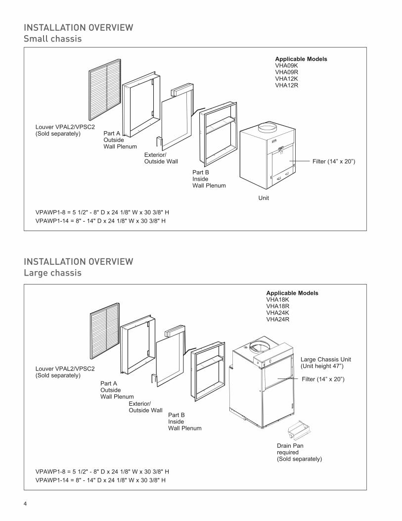
INSTALLATION OVERVIEWSmall chassis
Louver VPAL2/VPSC2(Sold separately)
Exterior/ Outside Wall
Part B InsideWall Plenum
Unit
Part A OutsideWall Plenum
Applicable ModelsVHA09KVHA09RVHA12KVHA12R
Filter (14” x 20”)
Louver VPAL2/VPSC2 (Sold separately)
Exterior/ Outside Wall
Part B InsideWall Plenum
Part A OutsideWall Plenum
Large Chassis Unit(Unit height 47”)
Drain Pan required (Sold separately)
Filter (14” x 20”)
VPAWP1-8 = 5 1/2" - 8" D x 24 1/8" W x 30 3/8" HVPAWP1-14 = 8" - 14" D x 24 1/8" W x 30 3/8" H
INSTALLATION OVERVIEWLarge chassis
VPAWP1-8 = 5 1/2" - 8" D x 24 1/8" W x 30 3/8" HVPAWP1-14 = 8" - 14" D x 24 1/8" W x 30 3/8" H
Applicable ModelsVHA18KVHA18RVHA24KVHA24R
5
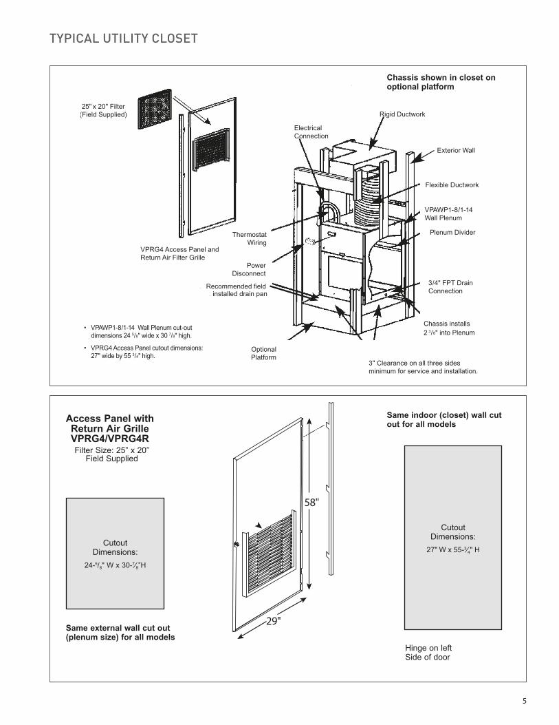
TYPICAL UTILITY CLOSET
58"
29"
Cutout Dimensions:
27" W x 55-3⁄4" H
Hinge on left Side of door
Cutout Dimensions:
24-5/8" W x 30-7⁄8”H
Same external wall cut out (plenum size) for all models
Same indoor (closet) wall cut out for all models
VPRG4 Access Panel andReturn Air Filter Grille
ElectricalConnection
Rigid Ductwork
Flexible Ductwork
Exterior Wall
VPAWP1-8/1-14Wall Plenum
Plenum Divider
3/4" FPT DrainConnection
OptionalPlatform
3" Clearance on all three sidesminimum for service and installation.
PowerDisconnect
Wiring
Chassis installs2 3/8" into Plenum
VPAWP1-8/1-14 Wall Plenum cut-outdimensions 24 5/8" wide x 30 7/8" high.
VPRG4 Access Panel cutout dimensions:27" wide by 55 3/4" high.
Recommended eldinstalled drain pan
25" x 20" Filter(Field Supplied)
Thermostat
Chassis shown in closet on optional platform
Access Panel with Return Air Grille VPRG4/VPRG4RFilter Size: 25” x 20”
Field Supplied

6
ACCESSORIES DIMENSIONSVPAL2 / VPSC2 Louver
VPAWP1-8 Wall Plenum
Cutout Dimensions:
24-5/8" W x 30-7⁄8”H
Architectural Louver VPAL2/VPSC2
25-9/16”
31-1/16”
Wall PlenumVPAWP1-8 - telescopes from 5-1/2” to 8” VPAWP1-14 - telescopes from 8” to 14”
A
B
30-3/8"
24-1/8"

7
ACCESSORIES DIMENSIONS
Cutout Dimensions:28”W x 48”H
30”
50”Access Panel with Return Air GrilleVPRG4/VPRG4RFilter Size: 20” x 20”
Field Supplied

8
EXTENDED COOLING PERFORMANCE
OUTDOOR DRY BULB TEMP. (DEGREES F AT 40% R.H.)
75 85 95 105 110
INDOOR WET BULB TEMP. (DEGREES F AT 80 F D.B.)
72 67 62 72 67 62 72 67 62 72 67 62 72 67 62
VHA09K
BTUH 11054 10631 9842 10528 9926 9156 10114 9400 8319 9475 8413 7417 8954 7835 6914
WATTS 738 750 758 805 813 823 905 905 905 978 977 980 1023 1022 1026
AMPS 3.6 3.6 3.6 3.8 3.8 3.9 4.3 4.3 4.3 4.6 4.6 4.6 4.8 4.8 4.9
SHR 0.53 0.72 0.96 0.54 0.74 0.98 0.54 0.77 0.99 0.55 0.81 0.99 0.57 0.84 0.99
VHA12K
BTUH 14347 13798 12773 13664 12883 11883 13127 12200 10797 12298 10919 9626 11621 10169 8973
WATTS 996 1011 1022 1085 1096 1109 1220 1220 1220 1319 1318 1321 1379 1378 1383
AMPS 4.7 4.7 4.8 5.1 5.1 5.1 5.7 5.7 5.7 6.1 6.1 6.2 6.4 6.4 6.4
SHR 0.51 0.70 0.94 0.52 0.72 0.96 0.53 0.75 0.96 0.54 0.79 0.97 0.55 0.82 0.96
VHA18K
BTUH 21403 20584 19055 20384 19219 17727 19583 18200 16107 18346 16289 14360 17336 15170 13386
WATTS 1489 1513 1529 1622 1639 1659 1825 1825 1825 1973 1971 1976 2062 2061 2069
AMPS 7.1 7.2 7.2 7.7 7.7 7.7 8.6 8.6 8.6 9.3 9.3 9.3 9.7 9.7 9.7
SHR 0.46 0.62 0.84 0.47 0.65 0.86 0.47 0.67 0.86 0.48 0.71 0.87 0.49 0.73 0.86
VHA24K
BTUH 27048 26013 24081 25760 24288 22402 24748 23000 20355 23184 20585 18147 21908 19171 16917
WATTS 2062 2095 2118 2247 2269 2297 2527 2527 2527 2732 2729 2737 2856 2854 2864
AMPS 9.0 9.1 9.2 9.7 9.8 9.8 10.8 10.9 11.0 11.7 11.7 11.8 12.3 12.3 12.3
SHR 0.48 0.65 0.88 0.49 0.68 0.89 0.49 0.70 0.90 0.50 0.74 0.90 0.52 0.76 0.90
VHA09R
BTUH 11054 10631 9842 10528 9926 9156 10114 9400 8319 9475 8413 7417 8954 7835 6914
WATTS 747 759 767 813 822 832 915 915 915 989 988 991 1034 1033 1037
AMPS 2.9 2.9 2.9 3.1 3.1 3.2 3.5 3.5 3.5 3.8 3.8 3.8 3.9 3.9 4.0
SHR 0.53 0.72 0.96 0.54 0.74 0.98 0.54 0.77 0.99 0.55 0.81 0.99 0.57 0.84 0.99
VHA12R
BTUH 14582 14024 12983 13888 13094 12078 13342 12400 10974 12499 11098 9784 11811 10335 9120
WATTS 1012 1028 1039 1102 1114 1127 1240 1240 1240 1340 1339 1343 1401 1401 1406
AMPS 4.2 4.2 4.3 4.5 4.6 4.6 5.1 5.1 5.1 5.5 5.5 5.5 5.7 5.7 5.8
SHR 0.53 0.72 0.96 0.54 0.74 0.98 0.54 0.77 0.99 0.55 0.81 0.99 0.57 0.84 0.99
VHA18R
BTUH 21168 20358 18846 20160 19008 17532 19368 18000 15930 18144 16110 14202 17145 15003 13239
WATTS 1481 1505 1521 1614 1630 1650 1815 1815 1815 1962 1960 1966 2051 2050 2057
AMPS 6.3 6.3 6.4 6.8 6.8 6.8 7.6 7.6 7.6 8.2 8.2 8.2 8.6 8.6 8.6
SHR 0.45 0.61 0.83 0.46 0.64 0.84 0.46 0.66 0.85 0.48 0.70 0.85 0.49 0.72 0.85
VHA24R
BTUH 26460 25448 23558 25200 23760 21915 24210 22500 19913 22680 20138 17753 21431 18754 16549
WATTS 2020 2052 2074 2200 2223 2250 2475 2475 2475 2675 2673 2680 2797 2796 2805
AMPS 8.0 8.1 8.2 8.6 8.7 8.7 9.7 9.7 9.7 10.4 10.4 10.5 10.9 10.9 11.0
SHR 0.48 0.65 0.88 0.49 0.68 0.89 0.49 0.70 0.90 0.50 0.74 0.90 0.52 0.76 0.90
RATING POINT AHRI 390
9
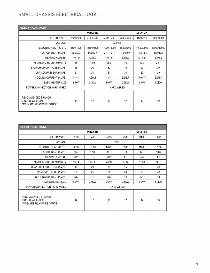
SMALL CHASSIS ELECTRICAL DATA
ELECTRICAL DATA
VHA09K VHA12K
HEATER WATTS 2500/2050 3400/2780 5000/4090 2500/2050 3400/2780 5000/4090
VOLTAGE 230/208
ELECTRIC HEATING BTU 8500/7000 11600/9500 17000/13900 8500/7000 11600/9500 17000/13900
HEAT CURRENT (AMPS) 10.9/9.9 14.8/13.4 21.7/19.7 10.9/9.9 14.8/13.4 21.7/19.7
HEATING AMPS HP 4.0/4.0 4.0/4.0 4.0/4.0 5.7/5.9 5.7/5.9 5.7/5.9
MINIMUM CIRCUIT AMPACITY 15 19.9 28.7 15 19.9 28.7
BRANCH CIRCUIT FUSE (AMPS) 15 20 30 15 20 30
LRA-COMPRESSOR (AMPS) 21 21 21 30 30 30
COOLING CURRENT (AMPS) 4.3/4.3 4.3/4.3 4.3/4.3 5.9/5.7 5.9/5.7 5.9/5.7
BASIC HEATER SIZE 2.5KW 3.4KW 5.0KW 2.5KW 3.4KW 5.0KW
POWER CONNECTION HARD WIRED HARD WIRED
RECOMMENDED BRANCH CIRCUIT WIRE SIZES *AWG- AMERICAN WIRE GAUGE
14 12 10 12 12 10
ELECTRICAL DATA
VHA09R VHA12R
HEATER WATTS 2500 3400 5000 2500 3400 5000
VOLTAGE 265
ELECTRIC HEATING BTU 8500 11600 17000 8500 11600 17000
HEAT CURRENT (AMPS) 9.4 12.8 18.8 9.4 12.8 18.8
HEATING AMPS HP 3.2 3.2 3.2 4.5 4.5 4.5
MINIMUM CIRCUIT AMPACITY 13.14 17.38 24.93 13.14 17.38 24.93
BRANCH CIRCUIT FUSE (AMPS) 15 20 30 15 20 30
LRA-COMPRESSOR (AMPS) 21 21 21 30 30 30
COOLING CURRENT (AMPS) 3.5 3.5 3.5 5.1 5.1 5.1
BASIC HEATER SIZE 2.5KW 3.4KW 5.0KW 2.5KW 3.4KW 5.0KW
POWER CONNECTION HARD WIRED HARD WIRED
RECOMMENDED BRANCH CIRCUIT WIRE SIZES *AWG- AMERICAN WIRE GAUGE
14 12 10 12 12 10
10
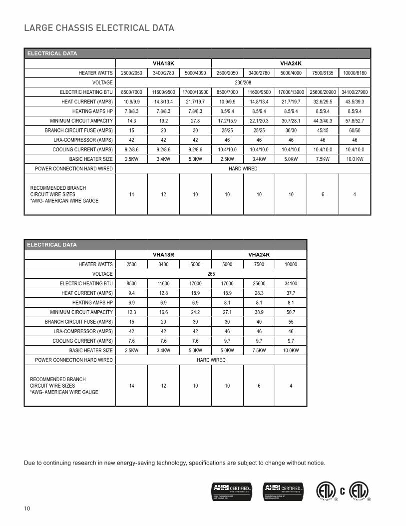
Due to continuing research in new energy-saving technology, specifications are subject to change without notice.
LARGE CHASSIS ELECTRICAL DATA
ELECTRICAL DATA
VHA18K VHA24K
HEATER WATTS 2500/2050 3400/2780 5000/4090 2500/2050 3400/2780 5000/4090 7500/6135 10000/8180
VOLTAGE 230/208
ELECTRIC HEATING BTU 8500/7000 11600/9500 17000/13900 8500/7000 11600/9500 17000/13900 25600/20900 34100/27900
HEAT CURRENT (AMPS) 10.9/9.9 14.8/13.4 21.7/19.7 10.9/9.9 14.8/13.4 21.7/19.7 32.6/29.5 43.5/39.3
HEATING AMPS HP 7.8/8.3 7.8/8.3 7.8/8.3 8.5/9.4 8.5/9.4 8.5/9.4 8.5/9.4 8.5/9.4
MINIMUM CIRCUIT AMPACITY 14.3 19.2 27.8 17.2/15.9 22.1/20.3 30.7/28.1 44.3/40.3 57.8/52.7
BRANCH CIRCUIT FUSE (AMPS) 15 20 30 25/25 25/25 30/30 45/45 60/60
LRA-COMPRESSOR (AMPS) 42 42 42 46 46 46 46 46
COOLING CURRENT (AMPS) 9.2/8.6 9.2/8.6 9.2/8.6 10.4/10.0 10.4/10.0 10.4/10.0 10.4/10.0 10.4/10.0
BASIC HEATER SIZE 2.5KW 3.4KW 5.0KW 2.5KW 3.4KW 5.0KW 7.5KW 10.0 KW
POWER CONNECTION HARD WIRED HARD WIRED
RECOMMENDED BRANCH CIRCUIT WIRE SIZES *AWG- AMERICAN WIRE GAUGE
14 12 10 10 10 10 6 4
ELECTRICAL DATA
VHA18R VHA24R
HEATER WATTS 2500 3400 5000 5000 7500 10000
VOLTAGE 265
ELECTRIC HEATING BTU 8500 11600 17000 17000 25600 34100
HEAT CURRENT (AMPS) 9.4 12.8 18.9 18.9 28.3 37.7
HEATING AMPS HP 6.9 6.9 6.9 8.1 8.1 8.1
MINIMUM CIRCUIT AMPACITY 12.3 16.6 24.2 27.1 38.9 50.7
BRANCH CIRCUIT FUSE (AMPS) 15 20 30 30 40 55
LRA-COMPRESSOR (AMPS) 42 42 42 46 46 46
COOLING CURRENT (AMPS) 7.6 7.6 7.6 9.7 9.7 9.7
BASIC HEATER SIZE 2.5KW 3.4KW 5.0KW 5.0KW 7.5KW 10.0KW
POWER CONNECTION HARD WIRED HARD WIRED
RECOMMENDED BRANCH CIRCUIT WIRE SIZES *AWG- AMERICAN WIRE GAUGE
14 12 10 10 6 4

11
Application and Accessories (All models)• The use of a Friedrich wall plenum is required for instal-
lation. Plenum opening is 3/4" above the floor for 9,000 & 12,000 models, and 1 1/2" for 18,000 & 24,000 Btu models. (VPAWP1-8 / VPAWP1-14).
• Return air is accommodated with a return air filter attached to the unit or through the use of a return air filter grille. (VPRG4/VPRG4R).
• Exterior louvers are available in anodized aluminum (VPAL2) or in custom painted colors (VPSC2).
• Unit is controlled by a remote wall-mounted thermostat. Friedrich model WRT1 wireless digital thermostat, RT6 wired digital thermostat, RT6P wired programmable thermostat, or EMRT1/EMWRT1 Energy Management Stats are recom-mended.
• Central desk control ready.
Typical Closet Arrangement
Cutaway of a typical closet shown with Vert-I-Pak® chassis installed in the wall sleeve. The unit has the thermostat, field wiring, internal drain and flex duct attached. VPRG4 return air filter holder and access panel are shown below.
The closet access panel may be installed in the front (as shown below) or to the left or right side of the unit. All three installation options will allow easy access to the unit for removal and replacement.
Application and InstallationInstallation Guidelines
• Chassis is to be installed against an exterior wall. Wall cutout dimensions will be 24 5/8" w x 30 7/8" h.
• Closet should allow for a minimum of three inches on three sides of the unit for return air, drain connections and change outs.
• Minimum recommended access door rough-in measure-ments 27" wide by 55 3/4" high (for VPRG4/VPRG4R).
• Friedrich recommends the use of a platform between 24" and 36" above the floor, for ease of installation and service-ability.
• Duct outlet designed for external static pressures up to .3" on 9,000, 12,000, and 18,000 Btu models; and .4" on 24,000 Btu models.
• Wall plenum allows chassis to be inserted 2 3/8" into plenum, thereby minimizing closet dimensions.
• Quick connect drain coupling ships standard to make installation and removal easier.
Application and Accessories (24K Models only)
• 18K and 24K utilize drain pan (VPDP1) that can be installed prior to chassis for simplified installation and removal.
• 18K and 24K utilize the same wall plenum as other units to give consistent exterior appearance. VHA24 plenum must be installed 1 1/2" above chassis platform.
9,000 & 12,000 Btu
10"
23 1/8" 23 1/8"
32 1/4"
18,000 & 24,000 Btu
10"
47 1/4"
23 1/8" 23 1/8"

12
OPTIONAL ACCESSORIES
ARCHITECTURAL LOUVER
VPAL2 and VPSC2
Extruded aluminum grille that attaches to the outdoor section of the wall plenum. Takes in fresh air and returns condensed air. VPSC2 can be ordered in custom colors.
DIMENSIONS: 25 9/16" W x 31 1/16" H
WALL PLENUM
VPAWP1-8, VPAWP1-14
Two-part sleeve that telescopes in and out. Sits inside the exterior wall penetration.
VPAWP1-8 telescopes from 5 1/2”–8” VPAWP1-14 telescopes from 8”–14”
DIMENSIONS: 24 1/8” W x 30 3/8” H CUTOUT DIMENSIONS: 24 5/8” W x 30 7/8” H
RETURN AIR GRILLE/ACCESS PANEL
VPRG4 / VPRG4R
Hinged panel allows access to unit and return air filter. A field-supplied filter (25” x 20”) should be mounted on the inside grille. Panel can be mounted with return air openings high or low on the door for optimum sound attenuation.
DIMENSIONS: 29” W x 58” H CUTOUT DIMENSIONS: 27” W x 55 3/4” H
FIRST COMPANY SLEEVE ADAPTER
VPASA1Single piece, welded adapter allows retrofit into existing First Company SPXR-series single package vertical unit wall sleeve and louver. Easy connection to Friedrich chassis.
SINGLE STAGE THERMOSTATS
RT6P Wired, single stage, wall-mounted programmable thermostat has two fan speeds and backlight. Controls Friedrich VERT-I-PAK. RT6 Wired, single stage, wall-mounted digital thermostat with two fan speeds and backlight for control of Friedrich VERT-I-PAK.
WRT1 Wireless, single stage, wall-mounted digital thermostat with two fan speeds and backlight for control of Friedrich VERT-I-PAK.
ENERGY MANAGEMENT THERMOSTATS
EMRT1Wired thermostat with occupancy sensor.
EMWRT1Wireless thermostat with occupancy sensor.
EMOCT EMRAF EMRHCFOnline connection kit. Remote access fee. Remote humidity control fee.
DRAIN PAN
VPDP1 For VHA18 and VHA24 models. May be installed prior to chassis for easy installation/removal.
RT6 WRT1
EMRT1, EMWRT1
VPAL2
VPAWP1-8
VPRG4/VPRG4R
VPASA1
VPDP1
13
All units shall be factory assembled, piped, wired and fully charged with R-410A. All units shall be certified in accordance with ARI Standard 390 for Single Packaged Vertical Heat Pumps. Units shall be ETL listed and carry a ETL label. All units shall be factory run-tested to check operation and be manufactured by Friedrich or equivalent.
The basic unit shall not exceed 23 1/8" wide x 23 1/8" deep. Overall height of the unit from the bottom of the isolators to the top of the duct collar shall not exceed 32 ¼" for models up to 12,000 Btu and 47 ¼" for models up to 24,000 Btu. The unit shall be designed so that the unit will insert into a factory supplied wall plenum 2 3/8" to minimize room intrusion. Factory supplied wall plenums shall allow for installation through walls from 4 ½" – 14" in thickness. Wall plenums will be adjustable to minimize installation clear-ances. Unit shall draw in ambient air through upper portion of an outside architectural louver measuring 25 9/16" wide x 31 1/16" high and shall exhaust heated air out through the lower portion of the louver. The unit shall be secured to the architectural lou-ver by means of a two part, weather-resistant wall plenum. The unit shall be capable of left, right or straight-in installations into mechanical closet without field modifications.
REFRIGERATION SYSTEM – The refrigeration system shall be hermetically sealed and consist of a rotary compressor that is externally mounted on vibration isolators no smaller than 1 ¾" diameter x 1 ½" high; condenser and evaporator coils constructed of copper tubes and aluminum plate fins; and capillaries as expansion devices. Unit shall have a fan slinger ring to increase efficiency and condensate disposal. A primary condensate removal system consisting of ¾" FTP fittings on multiple locations shall exist. A secondary overflow from the primary drain pan shall expel water to the outside of the building through the wall plenum and louver in the event that the primary drain line clogs.
AIR HANDLING SECTION – The condenser fan shall be driven by a single, totally enclosed, ball bearing, permanently lubricated split capacitor fan motor for models up to 12,000 Btu. 18,000 and 24,000 Btu models shall utilize a separate motor for both the indoor and outdoor air sections. Airflow shall be directed vertically up through a standard 10" flex duct starter collar and into flexible or rigid ducts to be distributed into the conditioned area. Starter collar shall have both crimped edge to ease flex duct installation and a waistline to prevent duct from loosening.
The chassis shall have a built-in damper capable of providing at least 60 CFM of fresh air into the conditioned area. A fine mesh screen shall filter the incoming fresh air. The damper can be controlled by a slide lever located on the front of the unit.
CONTROLS – The unit shall be factory equipped with terminal strip for connection to a standard 24-volt single-stage heat/cool thermostat. A 24-volt transformer shall be included and factory wired. Low voltage inputs will include: C (common), R (24V power), Y (cooling), G (fan), W (heat) and B (reversing valve on VHA heat pumps only).The unit shall be hard-wired and have a quick-disconnect to disable power for control box service.
An emergency heat override switch must be available to allow operation of the resistance heater in the event of a compressor failure on heat pump models.
GENERAL CONSTRUCTION – The unit shall be constructed of 18-gauge galvanized zinc-coated steel. The unit shall feature ½" foil backed insulation for sound and thermal efficiency.
The wall plenum (required factory accessory) shall be shipped separately and constructed of 20-gauge galvanized zinc-coated steel; pretreated with zinc-phosphate and sealed with a chro-mate rinse, then powder-coated for maximum coverage and protection. The plenum shall be black in color for minimal visibility of unit from exterior of building. The plenum shall be shipped with a protective weatherboard for use prior to final installation of the louver and chassis.
The architectural louver (required factory accessory) shall be shipped separately and fabricated from extruded anodized aluminum with louvers in the horizontal plane.
The unit shall include vibration isolators mounted under the chassis and a nonrigid plenum-to-chassis connection to isolate vibrations to the building.
The unit shall have a plastic fan, fan shroud, and drain pan; and aluminum outdoor coil endplates for corrosion protection and to help prevent rust on the side of the building below the outdoor louver.
The unit shall be shipped with return air filter brackets and a 14" x 20" filter affixed directly on to the unit chassis. Optional return air grilles and access panels shall be available as factory acces-sories for installation in the wall or door of the mechanical closet.
CORROSION PROTECTION - The unit shall feature corrosion -resistant materials and finish to help prevent deterioration.
The outdoor coil shall have Diamonblue advanced corrosion pro-tection consisting of hydrophilic-coated fins to prolong the life of the coil in all applications including seacoast protection.
ACCESSORY ACCESS PANEL - An optional factory-supplied access panel shall be available to provide access to the unit and adequate return air. The panel shall feature a filter holder to accept a field supplied 25” x 20” x 1” filter. Kit shall contain a hinge bracket for mounting the door with the return air openings high or low on the door for optimal sound attenuation. For 9,000 and 12,000 Btu models it is recommended to install the door with the hinge on the right side and the return air openings high on the door. For 18,000 and 24,000 Btu models it is recommended to install the hinge on the left with the openings low on the door.
WARRANTY – The warranty is one year on all parts and labor and 5 years on the sealed system, parts and labor, including compressor, indoor and outdoor coils and refrigerant tubing.
HVAC Engineering SpecificationsA-Series Vertical Packaged Heat Pumps
Cooling: 9400 – 23000 Btu
Heating: 8400 – 20000 Btu (Heat Pump)
Friedrich Models: VHA – Heat Pump with electric heat

14
Vert-I-Pak®
Single Package Heat Pumps
MODEL IDENTIFICATION GUIDE
Electric Heater SizeA Series25 = 2.5 KW34 = 3.4 KW50 = 5.0 KW75 = 7.5 KW*10 = 10 KW*
MODEL NUMBER V H A 09 K 34 RT P
Marketing Model
OptionsRT = Standard Remote Operation
* 24000 Btu only. VoltageK = 208/230V-1Ph-60HzR = 265V-2Ph-60Hz
Nominal CapacityA Series (Btu)09 = 9,000 18 = 18,000 12 = 12,000 24 = 24,000
SeriesVHA=Vertical Heat Pump
Refer to electrical data chart for heater/unit compatibility.
PURCHASER P.O. # DATE
PROJECT LOCATION
ENGINEER ARCHITECT
SUBMITTED BY FOR APPROVAL FOR REFERENCE
ITEM PLAN DESIGNATION QUANTITY COOLING Btu VOLTAGE FRIEDRICH MODEL
A-SERIES ACCESSORIES (Wall Plenum and Outdoor Louver are required)VPAWP1-8 Adjustable Wall Plenum (5 ½"- 8") Qty
VPAWP1-14 Adjustable Wall Plenum (8"-14") Qty
VPAL2 Architectural Louver Qty
VPSC2 Architectural Louver (color matched) Qty
VPASA1 Sleeve adapter for exact fit in existing First Company SPXR-series Qty
VPRG4 Return Air Grille/Access Panel Qty
VPDP1 Drain Pan for all A Series 24,000 Btu Qty
RT6 Wired Digital Wall Thermostat Qty
WRT1 Wireless Digital Wall Thermostat Qty
EMRT1 Wired Thermostat with Occupancy Sensor Qty
EMWRT1 Wireless Thermostat with Occupancy Sensor Qty
EMOCT Online Connection Kit Qty
EMRAF Remote Access Fee Qty
EMRHCF Energy Management Remote Humidity Control Fee Qty
VERT-I-PAK® SUBMITTAL_2017

15
SAVE THIS CERTIFICATE. It gives you specific rights. You may also have other rights which may vary from state to state and province to province.
In the event that your unit needs servicing, contact your nearest authorized service center. If you do not know the nearest service center, ask the com-pany that installed your unit or contact use - see address and telephone number above. To obtain service and/or warranty parts replacement, you must notify an authorized FRIEDRICH Air Conditioning Co. service center, distributor, dealer, or contractor of any defect within the applicable warranty period.
When requesting service: please have the model and serial number from your unit readily available.
Unless specified otherwise herein, the following applies:FRIEDRICH VERT-I-PAK A SERIES HEAT PUMPS & AIR CONDITIONERS
LIMITED WARRANTY - FIRST YEAR (Twelve (12) months from the date of installation). Any part found to be defective in the material or workman-ship will be repaired or replaced free of charge by our authorized service center during the normal working hours; and
LIMITED WARRANTY - SECOND THROUGH FIFTH YEAR (Sixty (60) months from the date of installation). ON THE SEALED REFRIGERATION SYSTEM. Any part of the sealed refrigeration system that is defective in material or workmanship will be repaired or replaced free of charge (excluding freight charges) by our authorized service center during normal working hours. The sealed refrigeration system consists of the compressor, metering device, evaporator, condenser, reversing valve, check valve, and the interconnecting tubing.
These warranties apply only while the unit remains at the original site and only to units installed inside the continental United States, Alaska, Hawaii, Puerto Rico, Mexico and Canada. The warranty applies only if the unit is installed and operated in accordance with the printed instruc-tions and in compliance with applicable local installation and building codes and good trade practices. For international warranty information, contact the Friedrich Air Conditioning Company - International Division.
Any defective part to be replaced must be made available to FRIEDRICH in exchange for the replacement part. Reasonable proof must be presented to establish the date of install, otherwise the beginning date of this certificate will be considered to be our shipment date plus sixty days. Replacement parts can be new or re-manufactured. Replacement parts and labor are only warranted for any unused portion of the unit’s warranty.
We will not be responsible for and the user will pay for:1. Service calls to: A) Instruct on unit operation. B) Replace house fuses or correct house wiring. C) Clean or replace air filters. D) Remove the unit from its installed location when not accessible for service required. E) Correct improper installations.
2. Parts or labor provided by anyone other than an authorized service center.
3. Damage caused by: A) Accident, abuse, negligence, misuse, riot, fire flood or acts of God. B) Operating the unit where there is a corrosive atmosphere containing chlorine, fluorine, or any damaging chemicals (other than in a normal residential environment). C) Unauthorized alteration or repair of the unit, which in turn affects its stability or performance. D) Failing to provide proper maintenance and service. E) Using and incorrect power source. F) Faulty installation or application of the unit.
We shall not be liable for any incidental, consequential, or special damages or expenses in connection with any use or failure of this unit. We have not made and do not make any representation or warranty of fitness for a particular use or purpose and there is no implied condition of fitness for a particular use or purpose. We make no expressed warranties except as stated in this certification No one is authorized to change this certificate or to create for us any other obligation or liability in connection with this unit. Any implied warranties shall last for one year after the original purchase date. Some states and provinces do not allow limitations on how long an implied warranty or condition lasts, so the above limitation or exclusions may not apply to you. The provisions of this warranty are in addition to and not a modification of or subtraction from the statutory warranties and other rights and remedies provided by law.
Performance of Friedrich’s Warranty obligation is limited to one of the following methods:1. Repair of the unit2. A refund to the customer for the prorated value of the unit based upon the remaining warranty period of the unit. 3. Providing a replacement unit of equal value
The method of fulfillment of the warranty obligation is at the sole discretion of Friedrich Air Conditioning.
In case of any questions regarding the provisions of this warranty, the English version will govern.
(11-10)
VERT-I-PAK® A SERIESSINGLE PACKAGE VERTICAL AIR CONDITIONERS
LIMITED WARRANTY
Friedrich Air Conditioning Company10001 Reunition Place, Suite 500
San Antonio, Tx 78216800.541.6645
www.friedrich.com

Friedrich Air Conditioning Co. l 10001 Reunion Place, Suite 500 l San Antonio, TX 78216 l 877.599.5665 l www.friedrich.com
PRPRF_VPAK_COMM_2017 (Rev.1) 9521 4200_01